

Page 1

User Guide
rp5400 Family of Servers
First Edition
Manufacturing Part Number : A5191-96018
November 2002
USA
© Copyright 2002
Page 2

Legal Notices
The information in this document is subject to change without notice.
Hewlett-Packard makes no warranty of any kind with regard to this manual, including, but not limited to, the
implied warranties of merchantability and fitness for a particular purpose. Hewlett-Packard shall not be held
liable for errors contained herein or direct, indirect, special, incidental or consequential damages in
connection with the furnishing, performance, or use of this material.
Restricted Rights Legend. Use, duplication or disclosure by the U.S. Government is subject to restrictions
as set forth in subparagraph (c) (1) (ii) of the Rights in Technical Data and Computer Software clause at
DFARS 252.227-7013 for DOD agencies, and subparagraphs (c) (1) and (c) (2) of the Commercial Computer
Software Restricted Rights clause at FAR 52.227-19 for other agencies.
HEWLETT-PACKARD COMPANY 3000 Hanover Street Palo Alto, California 94304 U.S.A.
Copyright Notices. ©copyright 1983-2002 Hewlett-Packard Company, all rights reserved.
Windows“, Windows NT“, Windows 95“, Windows 2000“, and Windows XP“ are registered trademarks of
Microsoft in the U.S. and other countries.
Reproduction, adaptation, or translation of this document without prior written permission is prohibited,
except as allowed under the copyright laws.
ii
Page 3

1. Server Overview
2. Server Unpacking and Installation
Factory Integrated rp54xx Cabinet Installation . . . . . . . . . . . . . . . . . . . . . . . . . . . . . . . . . . . . . . . . . . . . 4
Receive and Unpack A Non-Integrated Server . . . . . . . . . . . . . . . . . . . . . . . . . . . . . . . . . . . . . . . . . . . . . 7
Unpacking the server . . . . . . . . . . . . . . . . . . . . . . . . . . . . . . . . . . . . . . . . . . . . . . . . . . . . . . . . . . . . . . . . 7
Install Deskside Server . . . . . . . . . . . . . . . . . . . . . . . . . . . . . . . . . . . . . . . . . . . . . . . . . . . . . . . . . . . . . . . 10
Install Stand-Alone Server in a Cabinet. . . . . . . . . . . . . . . . . . . . . . . . . . . . . . . . . . . . . . . . . . . . . . . . . . 13
Stationary L-Bracket Rail Assembly . . . . . . . . . . . . . . . . . . . . . . . . . . . . . . . . . . . . . . . . . . . . . . . . . . . . 19
Identifying Approved Non-E-Series HP Cabinets. . . . . . . . . . . . . . . . . . . . . . . . . . . . . . . . . . . . . . . . . 19
Identifying E-Series HP Cabinets . . . . . . . . . . . . . . . . . . . . . . . . . . . . . . . . . . . . . . . . . . . . . . . . . . . . . 20
Identifying Static Rail Kit . . . . . . . . . . . . . . . . . . . . . . . . . . . . . . . . . . . . . . . . . . . . . . . . . . . . . . . . . . . 20
Installing Stationary Rails . . . . . . . . . . . . . . . . . . . . . . . . . . . . . . . . . . . . . . . . . . . . . . . . . . . . . . . . . . . 21
3. Installing Additional Components
Additional Components . . . . . . . . . . . . . . . . . . . . . . . . . . . . . . . . . . . . . . . . . . . . . . . . . . . . . . . . . . . . . . . 24
Installing Memory . . . . . . . . . . . . . . . . . . . . . . . . . . . . . . . . . . . . . . . . . . . . . . . . . . . . . . . . . . . . . . . . . . . 25
Memory Configuration Rules . . . . . . . . . . . . . . . . . . . . . . . . . . . . . . . . . . . . . . . . . . . . . . . . . . . . . . . . . 25
Installing Peripheral Component Interconnect (PCI) Cards . . . . . . . . . . . . . . . . . . . . . . . . . . . . . . . . . . 30
rp5400/rp5450 PCI Card Slots . . . . . . . . . . . . . . . . . . . . . . . . . . . . . . . . . . . . . . . . . . . . . . . . . . . . . . . . 30
rp5470 PCI Card Slots . . . . . . . . . . . . . . . . . . . . . . . . . . . . . . . . . . . . . . . . . . . . . . . . . . . . . . . . . . . . . . 31
PCI I/O Card Installation Restrictions . . . . . . . . . . . . . . . . . . . . . . . . . . . . . . . . . . . . . . . . . . . . . . . . . 32
PCI I/O Card Installation Order . . . . . . . . . . . . . . . . . . . . . . . . . . . . . . . . . . . . . . . . . . . . . . . . . . . . . . 32
Installing a PCI Card . . . . . . . . . . . . . . . . . . . . . . . . . . . . . . . . . . . . . . . . . . . . . . . . . . . . . . . . . . . . . . . 34
Online Addition/Replacement (OLA/R) of PCI I/O cards . . . . . . . . . . . . . . . . . . . . . . . . . . . . . . . . . . . 36
Installing Graphics . . . . . . . . . . . . . . . . . . . . . . . . . . . . . . . . . . . . . . . . . . . . . . . . . . . . . . . . . . . . . . . . . . 37
Graphics Troubleshooting . . . . . . . . . . . . . . . . . . . . . . . . . . . . . . . . . . . . . . . . . . . . . . . . . . . . . . . . . . . 43
Installing Disk Drives . . . . . . . . . . . . . . . . . . . . . . . . . . . . . . . . . . . . . . . . . . . . . . . . . . . . . . . . . . . . . . . . 44
Contents
4. Cable Connections
Core I/O Connections . . . . . . . . . . . . . . . . . . . . . . . . . . . . . . . . . . . . . . . . . . . . . . . . . . . . . . . . . . . . . . . . . 48
Revision A GSP . . . . . . . . . . . . . . . . . . . . . . . . . . . . . . . . . . . . . . . . . . . . . . . . . . . . . . . . . . . . . . . . . . . . 48
Revision B GSP . . . . . . . . . . . . . . . . . . . . . . . . . . . . . . . . . . . . . . . . . . . . . . . . . . . . . . . . . . . . . . . . . . . . 49
Guardian Service Processor (GSP) Overview. . . . . . . . . . . . . . . . . . . . . . . . . . . . . . . . . . . . . . . . . . . . . . 51
GSP LAN . . . . . . . . . . . . . . . . . . . . . . . . . . . . . . . . . . . . . . . . . . . . . . . . . . . . . . . . . . . . . . . . . . . . . . . . . 51
GSP RS-232. . . . . . . . . . . . . . . . . . . . . . . . . . . . . . . . . . . . . . . . . . . . . . . . . . . . . . . . . . . . . . . . . . . . . . . 51
GSP Features . . . . . . . . . . . . . . . . . . . . . . . . . . . . . . . . . . . . . . . . . . . . . . . . . . . . . . . . . . . . . . . . . . . . . 51
Revision A GSP . . . . . . . . . . . . . . . . . . . . . . . . . . . . . . . . . . . . . . . . . . . . . . . . . . . . . . . . . . . . . . . . . . . . 52
Revision B GSP . . . . . . . . . . . . . . . . . . . . . . . . . . . . . . . . . . . . . . . . . . . . . . . . . . . . . . . . . . . . . . . . . . . . 52
Configure System Consoles . . . . . . . . . . . . . . . . . . . . . . . . . . . . . . . . . . . . . . . . . . . . . . . . . . . . . . . . . . . . 53
GSP Cables . . . . . . . . . . . . . . . . . . . . . . . . . . . . . . . . . . . . . . . . . . . . . . . . . . . . . . . . . . . . . . . . . . . . . . . 54
Configure RS-232 Console . . . . . . . . . . . . . . . . . . . . . . . . . . . . . . . . . . . . . . . . . . . . . . . . . . . . . . . . . . . 54
Configure Remote Console . . . . . . . . . . . . . . . . . . . . . . . . . . . . . . . . . . . . . . . . . . . . . . . . . . . . . . . . . . . 58
Configure the LAN Console . . . . . . . . . . . . . . . . . . . . . . . . . . . . . . . . . . . . . . . . . . . . . . . . . . . . . . . . . . 59
Configure the Web Console . . . . . . . . . . . . . . . . . . . . . . . . . . . . . . . . . . . . . . . . . . . . . . . . . . . . . . . . . . 61
Secure Web Console Installation. . . . . . . . . . . . . . . . . . . . . . . . . . . . . . . . . . . . . . . . . . . . . . . . . . . . . . . . 66
iii
Page 4

Contents
GSP Configurable Parameters . . . . . . . . . . . . . . . . . . . . . . . . . . . . . . . . . . . . . . . . . . . . . . . . . . . . . . . . . 69
Adding Users. . . . . . . . . . . . . . . . . . . . . . . . . . . . . . . . . . . . . . . . . . . . . . . . . . . . . . . . . . . . . . . . . . . . . . 69
Removing Users . . . . . . . . . . . . . . . . . . . . . . . . . . . . . . . . . . . . . . . . . . . . . . . . . . . . . . . . . . . . . . . . . . . 70
Return the GSP to Default Configurations . . . . . . . . . . . . . . . . . . . . . . . . . . . . . . . . . . . . . . . . . . . . . . 71
rp54xx Server Boot Process . . . . . . . . . . . . . . . . . . . . . . . . . . . . . . . . . . . . . . . . . . . . . . . . . . . . . . . . . . . . 72
Initial Power-up . . . . . . . . . . . . . . . . . . . . . . . . . . . . . . . . . . . . . . . . . . . . . . . . . . . . . . . . . . . . . . . . . . . 74
5. Utilities
Configuring the Rev A Guardian Service Processor (GSP) . . . . . . . . . . . . . . . . . . . . . . . . . . . . . . . . . . . 78
Configuring the GSP LAN Port . . . . . . . . . . . . . . . . . . . . . . . . . . . . . . . . . . . . . . . . . . . . . . . . . . . . . . . 78
Adding Users. . . . . . . . . . . . . . . . . . . . . . . . . . . . . . . . . . . . . . . . . . . . . . . . . . . . . . . . . . . . . . . . . . . . . . 78
Removing Users . . . . . . . . . . . . . . . . . . . . . . . . . . . . . . . . . . . . . . . . . . . . . . . . . . . . . . . . . . . . . . . . . . . 80
Changing the Default GSP Configuration. . . . . . . . . . . . . . . . . . . . . . . . . . . . . . . . . . . . . . . . . . . . . . . 80
Configuring the Rev B Guardian Service Processor (GSP) . . . . . . . . . . . . . . . . . . . . . . . . . . . . . . . . . . . 81
Configuring the GSP LAN Port . . . . . . . . . . . . . . . . . . . . . . . . . . . . . . . . . . . . . . . . . . . . . . . . . . . . . . . 81
Adding Users. . . . . . . . . . . . . . . . . . . . . . . . . . . . . . . . . . . . . . . . . . . . . . . . . . . . . . . . . . . . . . . . . . . . . . 81
Removing Users . . . . . . . . . . . . . . . . . . . . . . . . . . . . . . . . . . . . . . . . . . . . . . . . . . . . . . . . . . . . . . . . . . . 83
Changing the Default GSP Configuration. . . . . . . . . . . . . . . . . . . . . . . . . . . . . . . . . . . . . . . . . . . . . . . 83
6. Troubleshooting
Determine Current System State . . . . . . . . . . . . . . . . . . . . . . . . . . . . . . . . . . . . . . . . . . . . . . . . . . . . . . . 86
Troubleshooting and FRU identification . . . . . . . . . . . . . . . . . . . . . . . . . . . . . . . . . . . . . . . . . . . . . . . . . 87
Problem Symptoms and Repair Actions . . . . . . . . . . . . . . . . . . . . . . . . . . . . . . . . . . . . . . . . . . . . . . . . 87
Chassis Code to FRU Decode . . . . . . . . . . . . . . . . . . . . . . . . . . . . . . . . . . . . . . . . . . . . . . . . . . . . . . . . . . 91
Cross-Referencing Chassis Log Errors to rp54xx FRUs. . . . . . . . . . . . . . . . . . . . . . . . . . . . . . . . . . . . 91
Interpreting System Alerts . . . . . . . . . . . . . . . . . . . . . . . . . . . . . . . . . . . . . . . . . . . . . . . . . . . . . . . . . . 94
Interpreting Service Processor Error Chassis Logs . . . . . . . . . . . . . . . . . . . . . . . . . . . . . . . . . . . . . . . 96
Interpreting Chassis Logs Using the chassis_code.codes File . . . . . . . . . . . . . . . . . . . . . . . . . . . . . . . 98
rp5400 and rp5450 System Block Diagram . . . . . . . . . . . . . . . . . . . . . . . . . . . . . . . . . . . . . . . . . . . . . . 100
rp5400 and rp5450 I/O Block Diagram . . . . . . . . . . . . . . . . . . . . . . . . . . . . . . . . . . . . . . . . . . . . . . . . . . 101
rp5430 and rp5470 System Block Diagram . . . . . . . . . . . . . . . . . . . . . . . . . . . . . . . . . . . . . . . . . . . . . . 102
rp5430 and rp5470 I/O Block Diagram . . . . . . . . . . . . . . . . . . . . . . . . . . . . . . . . . . . . . . . . . . . . . . . . . . 103
Run/Attention/Fault LED States . . . . . . . . . . . . . . . . . . . . . . . . . . . . . . . . . . . . . . . . . . . . . . . . . . . . . . 104
PCI I/O LED States . . . . . . . . . . . . . . . . . . . . . . . . . . . . . . . . . . . . . . . . . . . . . . . . . . . . . . . . . . . . . . . . . 112
Expansion I/O LED States . . . . . . . . . . . . . . . . . . . . . . . . . . . . . . . . . . . . . . . . . . . . . . . . . . . . . . . . . . . 114
GSP LED States. . . . . . . . . . . . . . . . . . . . . . . . . . . . . . . . . . . . . . . . . . . . . . . . . . . . . . . . . . . . . . . . . . . . 116
LAN/SCSI LED States. . . . . . . . . . . . . . . . . . . . . . . . . . . . . . . . . . . . . . . . . . . . . . . . . . . . . . . . . . . . . . . 118
Fan, Power Supply, and Disk LED States . . . . . . . . . . . . . . . . . . . . . . . . . . . . . . . . . . . . . . . . . . . . . . . 119
7. Removing and Replacing Components
List of Changeable Parts with Remove and Replace Components . . . . . . . . . . . . . . . . . . . . . . . . . . . . 122
Cardcage Fan . . . . . . . . . . . . . . . . . . . . . . . . . . . . . . . . . . . . . . . . . . . . . . . . . . . . . . . . . . . . . . . . . . . . 122
Core I/O . . . . . . . . . . . . . . . . . . . . . . . . . . . . . . . . . . . . . . . . . . . . . . . . . . . . . . . . . . . . . . . . . . . . . . . . . 122
HotSwap Chassis Fan. . . . . . . . . . . . . . . . . . . . . . . . . . . . . . . . . . . . . . . . . . . . . . . . . . . . . . . . . . . . . . 122
Disk Drive . . . . . . . . . . . . . . . . . . . . . . . . . . . . . . . . . . . . . . . . . . . . . . . . . . . . . . . . . . . . . . . . . . . . . . . 123
Display Board . . . . . . . . . . . . . . . . . . . . . . . . . . . . . . . . . . . . . . . . . . . . . . . . . . . . . . . . . . . . . . . . . . . . 123
iv
Page 5

Contents
Front Bezel . . . . . . . . . . . . . . . . . . . . . . . . . . . . . . . . . . . . . . . . . . . . . . . . . . . . . . . . . . . . . . . . . . . . . . 123
Memory DIMM . . . . . . . . . . . . . . . . . . . . . . . . . . . . . . . . . . . . . . . . . . . . . . . . . . . . . . . . . . . . . . . . . . . 123
PCI I/O Card . . . . . . . . . . . . . . . . . . . . . . . . . . . . . . . . . . . . . . . . . . . . . . . . . . . . . . . . . . . . . . . . . . . . . 124
Power Supply . . . . . . . . . . . . . . . . . . . . . . . . . . . . . . . . . . . . . . . . . . . . . . . . . . . . . . . . . . . . . . . . . . . . 124
HotSwap Power Converter Fan . . . . . . . . . . . . . . . . . . . . . . . . . . . . . . . . . . . . . . . . . . . . . . . . . . . . . . 124
Platform Monitor . . . . . . . . . . . . . . . . . . . . . . . . . . . . . . . . . . . . . . . . . . . . . . . . . . . . . . . . . . . . . . . . . 124
Processor Support Module . . . . . . . . . . . . . . . . . . . . . . . . . . . . . . . . . . . . . . . . . . . . . . . . . . . . . . . . . . 125
Individual Component Remove/Replace Instructions . . . . . . . . . . . . . . . . . . . . . . . . . . . . . . . . . . . . . . 126
Extend the Server out the Front . . . . . . . . . . . . . . . . . . . . . . . . . . . . . . . . . . . . . . . . . . . . . . . . . . . . . 126
Insert the Server from the Front . . . . . . . . . . . . . . . . . . . . . . . . . . . . . . . . . . . . . . . . . . . . . . . . . . . . 127
Stand-alone Server Cover Removal . . . . . . . . . . . . . . . . . . . . . . . . . . . . . . . . . . . . . . . . . . . . . . . . . . . 128
Stand-alone Server Cover Replacement . . . . . . . . . . . . . . . . . . . . . . . . . . . . . . . . . . . . . . . . . . . . . . . 130
Top Cover Removal . . . . . . . . . . . . . . . . . . . . . . . . . . . . . . . . . . . . . . . . . . . . . . . . . . . . . . . . . . . . . . . . 131
Top Cover Replacement . . . . . . . . . . . . . . . . . . . . . . . . . . . . . . . . . . . . . . . . . . . . . . . . . . . . . . . . . . . . 132
Side Cover Removal . . . . . . . . . . . . . . . . . . . . . . . . . . . . . . . . . . . . . . . . . . . . . . . . . . . . . . . . . . . . . . . 133
Side Cover Replacement. . . . . . . . . . . . . . . . . . . . . . . . . . . . . . . . . . . . . . . . . . . . . . . . . . . . . . . . . . . . 134
Front Bezel Removal (Single Piece) . . . . . . . . . . . . . . . . . . . . . . . . . . . . . . . . . . . . . . . . . . . . . . . . . . . 135
Front Bezel Replacement (Single Piece) . . . . . . . . . . . . . . . . . . . . . . . . . . . . . . . . . . . . . . . . . . . . . . . 136
Front Bezel Removal (Two Piece) . . . . . . . . . . . . . . . . . . . . . . . . . . . . . . . . . . . . . . . . . . . . . . . . . . . . 137
Front Bezel Replacement (Two Piece) . . . . . . . . . . . . . . . . . . . . . . . . . . . . . . . . . . . . . . . . . . . . . . . . . 138
Core I/O Removal . . . . . . . . . . . . . . . . . . . . . . . . . . . . . . . . . . . . . . . . . . . . . . . . . . . . . . . . . . . . . . . . . 139
Core I/O Replacement. . . . . . . . . . . . . . . . . . . . . . . . . . . . . . . . . . . . . . . . . . . . . . . . . . . . . . . . . . . . . . 140
PCI Card Separator/Extractor Removal . . . . . . . . . . . . . . . . . . . . . . . . . . . . . . . . . . . . . . . . . . . . . . . 142
PCI Card Separator/Extractor Replacement. . . . . . . . . . . . . . . . . . . . . . . . . . . . . . . . . . . . . . . . . . . . 143
HotPlug Disk Drive Removal . . . . . . . . . . . . . . . . . . . . . . . . . . . . . . . . . . . . . . . . . . . . . . . . . . . . . . . . 144
HotPlug Disk Drive Replacement . . . . . . . . . . . . . . . . . . . . . . . . . . . . . . . . . . . . . . . . . . . . . . . . . . . . 149
HotSwap Chassis Fan Cover Removal. . . . . . . . . . . . . . . . . . . . . . . . . . . . . . . . . . . . . . . . . . . . . . . . . 152
HotSwap Chassis Fan Cover Replacement . . . . . . . . . . . . . . . . . . . . . . . . . . . . . . . . . . . . . . . . . . . . . 153
HotSwap Chassis Fan Removal . . . . . . . . . . . . . . . . . . . . . . . . . . . . . . . . . . . . . . . . . . . . . . . . . . . . . . 154
HotSwap Chassis Fan Replacement . . . . . . . . . . . . . . . . . . . . . . . . . . . . . . . . . . . . . . . . . . . . . . . . . . 155
HotSwap Card Cage Fan Removal. . . . . . . . . . . . . . . . . . . . . . . . . . . . . . . . . . . . . . . . . . . . . . . . . . . . 156
HotSwap Card Cage Fan Replacement . . . . . . . . . . . . . . . . . . . . . . . . . . . . . . . . . . . . . . . . . . . . . . . . 157
HotSwap Power Supply Removal. . . . . . . . . . . . . . . . . . . . . . . . . . . . . . . . . . . . . . . . . . . . . . . . . . . . . 158
HotSwap Power Supply Replacement . . . . . . . . . . . . . . . . . . . . . . . . . . . . . . . . . . . . . . . . . . . . . . . . . 159
HotSwap Power Converter Fan Removal . . . . . . . . . . . . . . . . . . . . . . . . . . . . . . . . . . . . . . . . . . . . . . 160
HotSwap Power Converter Fan Replacement . . . . . . . . . . . . . . . . . . . . . . . . . . . . . . . . . . . . . . . . . . . 161
Processor Support Module Removal . . . . . . . . . . . . . . . . . . . . . . . . . . . . . . . . . . . . . . . . . . . . . . . . . . 162
Processor Support Module Replacement . . . . . . . . . . . . . . . . . . . . . . . . . . . . . . . . . . . . . . . . . . . . . . 163
Memory DIMM Removal . . . . . . . . . . . . . . . . . . . . . . . . . . . . . . . . . . . . . . . . . . . . . . . . . . . . . . . . . . . 164
Memory DIMM Replacement. . . . . . . . . . . . . . . . . . . . . . . . . . . . . . . . . . . . . . . . . . . . . . . . . . . . . . . . 165
Display Board Removal . . . . . . . . . . . . . . . . . . . . . . . . . . . . . . . . . . . . . . . . . . . . . . . . . . . . . . . . . . . . 166
Display Board Replacement . . . . . . . . . . . . . . . . . . . . . . . . . . . . . . . . . . . . . . . . . . . . . . . . . . . . . . . . . 167
Platform Monitor Removal. . . . . . . . . . . . . . . . . . . . . . . . . . . . . . . . . . . . . . . . . . . . . . . . . . . . . . . . . . 168
Platform Monitor Replacement . . . . . . . . . . . . . . . . . . . . . . . . . . . . . . . . . . . . . . . . . . . . . . . . . . . . . . 170
PCI I/O Card Removal . . . . . . . . . . . . . . . . . . . . . . . . . . . . . . . . . . . . . . . . . . . . . . . . . . . . . . . . . . . . . 172
PCI I/O Card Replacement. . . . . . . . . . . . . . . . . . . . . . . . . . . . . . . . . . . . . . . . . . . . . . . . . . . . . . . . . . 173
v
Page 6

Contents
A. Parts and Accessories
CRU Physical Location . . . . . . . . . . . . . . . . . . . . . . . . . . . . . . . . . . . . . . . . . . . . . . . . . . . . . . . . . . . . . . 176
Customer Replaceable Unit Part Numbers . . . . . . . . . . . . . . . . . . . . . . . . . . . . . . . . . . . . . . . . . . . . . . 179
B. System Specifications
Dimensions. . . . . . . . . . . . . . . . . . . . . . . . . . . . . . . . . . . . . . . . . . . . . . . . . . . . . . . . . . . . . . . . . . . . . . . . 182
Uncrating Space . . . . . . . . . . . . . . . . . . . . . . . . . . . . . . . . . . . . . . . . . . . . . . . . . . . . . . . . . . . . . . . . . . 182
Space Requirements . . . . . . . . . . . . . . . . . . . . . . . . . . . . . . . . . . . . . . . . . . . . . . . . . . . . . . . . . . . . . . . 182
Computer Room Physical Space Requirements . . . . . . . . . . . . . . . . . . . . . . . . . . . . . . . . . . . . . . . . . 183
Computer Room Unpacking Space . . . . . . . . . . . . . . . . . . . . . . . . . . . . . . . . . . . . . . . . . . . . . . . . . . . 184
Electrical. . . . . . . . . . . . . . . . . . . . . . . . . . . . . . . . . . . . . . . . . . . . . . . . . . . . . . . . . . . . . . . . . . . . . . . . . . 185
Office High Availability Requirements . . . . . . . . . . . . . . . . . . . . . . . . . . . . . . . . . . . . . . . . . . . . . . . . 185
Power Protection . . . . . . . . . . . . . . . . . . . . . . . . . . . . . . . . . . . . . . . . . . . . . . . . . . . . . . . . . . . . . . . . . . 185
Modular PDUs . . . . . . . . . . . . . . . . . . . . . . . . . . . . . . . . . . . . . . . . . . . . . . . . . . . . . . . . . . . . . . . . . . . 186
System Power Requirements . . . . . . . . . . . . . . . . . . . . . . . . . . . . . . . . . . . . . . . . . . . . . . . . . . . . . . . . 186
LAN and Telephone . . . . . . . . . . . . . . . . . . . . . . . . . . . . . . . . . . . . . . . . . . . . . . . . . . . . . . . . . . . . . . . . . 187
Acoustic Safety Standards. . . . . . . . . . . . . . . . . . . . . . . . . . . . . . . . . . . . . . . . . . . . . . . . . . . . . . . . . . . . 188
Altitude Operation Standards. . . . . . . . . . . . . . . . . . . . . . . . . . . . . . . . . . . . . . . . . . . . . . . . . . . . . . . . . 189
Effects of Altitude . . . . . . . . . . . . . . . . . . . . . . . . . . . . . . . . . . . . . . . . . . . . . . . . . . . . . . . . . . . . . . . . . 189
Temperature and Humidity Operating Standards . . . . . . . . . . . . . . . . . . . . . . . . . . . . . . . . . . . . . . . . 190
Thermal Protection Features . . . . . . . . . . . . . . . . . . . . . . . . . . . . . . . . . . . . . . . . . . . . . . . . . . . . . . . . 190
C. General Site Preparation Guidelines
Electrical Factors . . . . . . . . . . . . . . . . . . . . . . . . . . . . . . . . . . . . . . . . . . . . . . . . . . . . . . . . . . . . . . . . . . . 192
Computer Room Safety. . . . . . . . . . . . . . . . . . . . . . . . . . . . . . . . . . . . . . . . . . . . . . . . . . . . . . . . . . . . . 192
Power Consumption . . . . . . . . . . . . . . . . . . . . . . . . . . . . . . . . . . . . . . . . . . . . . . . . . . . . . . . . . . . . . . . 193
Electrical Load Requirements (Circuit Breaker Sizing). . . . . . . . . . . . . . . . . . . . . . . . . . . . . . . . . . . 193
Power Quality . . . . . . . . . . . . . . . . . . . . . . . . . . . . . . . . . . . . . . . . . . . . . . . . . . . . . . . . . . . . . . . . . . . . 193
Distribution Hardware . . . . . . . . . . . . . . . . . . . . . . . . . . . . . . . . . . . . . . . . . . . . . . . . . . . . . . . . . . . . . 194
Grounding Systems. . . . . . . . . . . . . . . . . . . . . . . . . . . . . . . . . . . . . . . . . . . . . . . . . . . . . . . . . . . . . . . . 195
System Installation Guidelines . . . . . . . . . . . . . . . . . . . . . . . . . . . . . . . . . . . . . . . . . . . . . . . . . . . . . . 197
Environmental Elements . . . . . . . . . . . . . . . . . . . . . . . . . . . . . . . . . . . . . . . . . . . . . . . . . . . . . . . . . . . . 198
Computer Room Preparation . . . . . . . . . . . . . . . . . . . . . . . . . . . . . . . . . . . . . . . . . . . . . . . . . . . . . . . . 198
Cooling Requirements . . . . . . . . . . . . . . . . . . . . . . . . . . . . . . . . . . . . . . . . . . . . . . . . . . . . . . . . . . . . . 198
Humidity Level . . . . . . . . . . . . . . . . . . . . . . . . . . . . . . . . . . . . . . . . . . . . . . . . . . . . . . . . . . . . . . . . . . . 200
Dust and Pollution Control . . . . . . . . . . . . . . . . . . . . . . . . . . . . . . . . . . . . . . . . . . . . . . . . . . . . . . . . . 200
Metallic Particulate Contamination . . . . . . . . . . . . . . . . . . . . . . . . . . . . . . . . . . . . . . . . . . . . . . . . . . 201
Electrostatic Discharge (ESD) Prevention . . . . . . . . . . . . . . . . . . . . . . . . . . . . . . . . . . . . . . . . . . . . . 202
Acoustics . . . . . . . . . . . . . . . . . . . . . . . . . . . . . . . . . . . . . . . . . . . . . . . . . . . . . . . . . . . . . . . . . . . . . . . . 202
Facility Characteristics . . . . . . . . . . . . . . . . . . . . . . . . . . . . . . . . . . . . . . . . . . . . . . . . . . . . . . . . . . . . . . 203
Floor Loading . . . . . . . . . . . . . . . . . . . . . . . . . . . . . . . . . . . . . . . . . . . . . . . . . . . . . . . . . . . . . . . . . . . . 203
Windows . . . . . . . . . . . . . . . . . . . . . . . . . . . . . . . . . . . . . . . . . . . . . . . . . . . . . . . . . . . . . . . . . . . . . . . . 205
Space Requirements. . . . . . . . . . . . . . . . . . . . . . . . . . . . . . . . . . . . . . . . . . . . . . . . . . . . . . . . . . . . . . . . . 206
Delivery Space Requirements . . . . . . . . . . . . . . . . . . . . . . . . . . . . . . . . . . . . . . . . . . . . . . . . . . . . . . . 206
Operational Space Requirements . . . . . . . . . . . . . . . . . . . . . . . . . . . . . . . . . . . . . . . . . . . . . . . . . . . . 206
Floor Plan Grid . . . . . . . . . . . . . . . . . . . . . . . . . . . . . . . . . . . . . . . . . . . . . . . . . . . . . . . . . . . . . . . . . . . 206
vi
Page 7

Contents
Typical Installation Schedule . . . . . . . . . . . . . . . . . . . . . . . . . . . . . . . . . . . . . . . . . . . . . . . . . . . . . . . . . 207
Site Inspection . . . . . . . . . . . . . . . . . . . . . . . . . . . . . . . . . . . . . . . . . . . . . . . . . . . . . . . . . . . . . . . . . . . . . 208
Delivery Survey . . . . . . . . . . . . . . . . . . . . . . . . . . . . . . . . . . . . . . . . . . . . . . . . . . . . . . . . . . . . . . . . . . . . 212
vii
Page 8

Contents
viii
Page 9

Tab les
Table 6-1. Problem Symptoms and Repair Actions . . . . . . . . . . . . . . . . . . . . . . . . . . . . . . . . . . . . . . 87
Table 6-2. Chassis Log Error to FRU Decoder . . . . . . . . . . . . . . . . . . . . . . . . . . . . . . . . . . . . . . . . . . 91
Table A-1. Exchange CRUs . . . . . . . . . . . . . . . . . . . . . . . . . . . . . . . . . . . . . . . . . . . . . . . . . . . . . . . . 179
Table A-2. Non-Exchange CRUs . . . . . . . . . . . . . . . . . . . . . . . . . . . . . . . . . . . . . . . . . . . . . . . . . . . . 180
Table B-1. Power Requirements . . . . . . . . . . . . . . . . . . . . . . . . . . . . . . . . . . . . . . . . . . . . . . . . . . . . 186
Table C-1. Effect of Humidity on ESD Charge Levels . . . . . . . . . . . . . . . . . . . . . . . . . . . . . . . . . . . 202
Table C-2. Floor Loading Term Definitions . . . . . . . . . . . . . . . . . . . . . . . . . . . . . . . . . . . . . . . . . . . 203
Table C-3. Typical Raised Floor Specifications. . . . . . . . . . . . . . . . . . . . . . . . . . . . . . . . . . . . . . . . . 204
Table C-4. Customer and Hewlett-Packard Information . . . . . . . . . . . . . . . . . . . . . . . . . . . . . . . . . 208
Table C-5. Site Inspection Checklist . . . . . . . . . . . . . . . . . . . . . . . . . . . . . . . . . . . . . . . . . . . . . . . . . 209
ix
Page 10

Table s
x
Page 11

Figures
Figure A-1. Server Rear View . . . . . . . . . . . . . . . . . . . . . . . . . . . . . . . . . . . . . . . . . . . . . . . . . . . . . . 176
Figure A-2. Side Service Bay . . . . . . . . . . . . . . . . . . . . . . . . . . . . . . . . . . . . . . . . . . . . . . . . . . . . . . . 177
Figure A-3. System Board (Access via Top Service Bay) . . . . . . . . . . . . . . . . . . . . . . . . . . . . . . . . . 177
Figure A-4. Server Front . . . . . . . . . . . . . . . . . . . . . . . . . . . . . . . . . . . . . . . . . . . . . . . . . . . . . . . . . . 178
Figure C-1. Raised Floor Metal Strip Ground System. . . . . . . . . . . . . . . . . . . . . . . . . . . . . . . . . . . 196
Figure C-2. Delivery Survey (Part 1) . . . . . . . . . . . . . . . . . . . . . . . . . . . . . . . . . . . . . . . . . . . . . . . . 213
Figure C-3. Delivery Survey (Part 2) . . . . . . . . . . . . . . . . . . . . . . . . . . . . . . . . . . . . . . . . . . . . . . . . 214
xi
Page 12

Figures
xii
Page 13

Preface
Printing History
The Printing History below identifies the edition dates of this manual. Updates are made to this publication
on an unscheduled, as needed, basis. The updates will consist of a complete replacement manual and
pertinent on-line or CD-ROM documentation.
First Edition . . . . . . . . . . . . . . . . . . . . . . . . . . . . . . . . . . . . . . . . . . . . . . . . . . . . . . . . November 2002
What’s New?
The, Upgrade Guide, rp5400 Family of Servers, is new and was developed to provide customers with system
maintenance information for those components called customer replaceable units (CRUs). Maintenance of
CRUs does not require HP customer engineering services, except when specifically cautioned. The cautions
are shown primarily to protect customer product warrantees.
xiii
Page 14

xiv
Page 15

1 Server Overview
The rp5400 family of servers are 1-way to 4-way servers based on the PA-RISC processor architecture. The
rp5400 family of servers accommodate up to 16GB of memory and internal peripherals including disks and
DVD ROM/Tape. High availability features include HotSwap fans and power supplies, and HotPlug internal
disk drives. The supported operating system is HP-UX.
Chapter 1
1
Page 16

Server Overview
2
Chapter 1
Page 17

2 Server Unpacking and Installation
Chapter 2
3
Page 18
Server Unpacking and Installation
Factory Integrated rp54xx Cabinet Installation
Factory Integrated rp54xx Cabinet Installation
A factory integrated server is one in which the rp54xx server and associated components are pre-assembled
and shipped from the factory already installed in a Hewlett-Packard E-Series cabinet. Factory integrated
systems reduce the amount of time required to set-up and begin server operation.
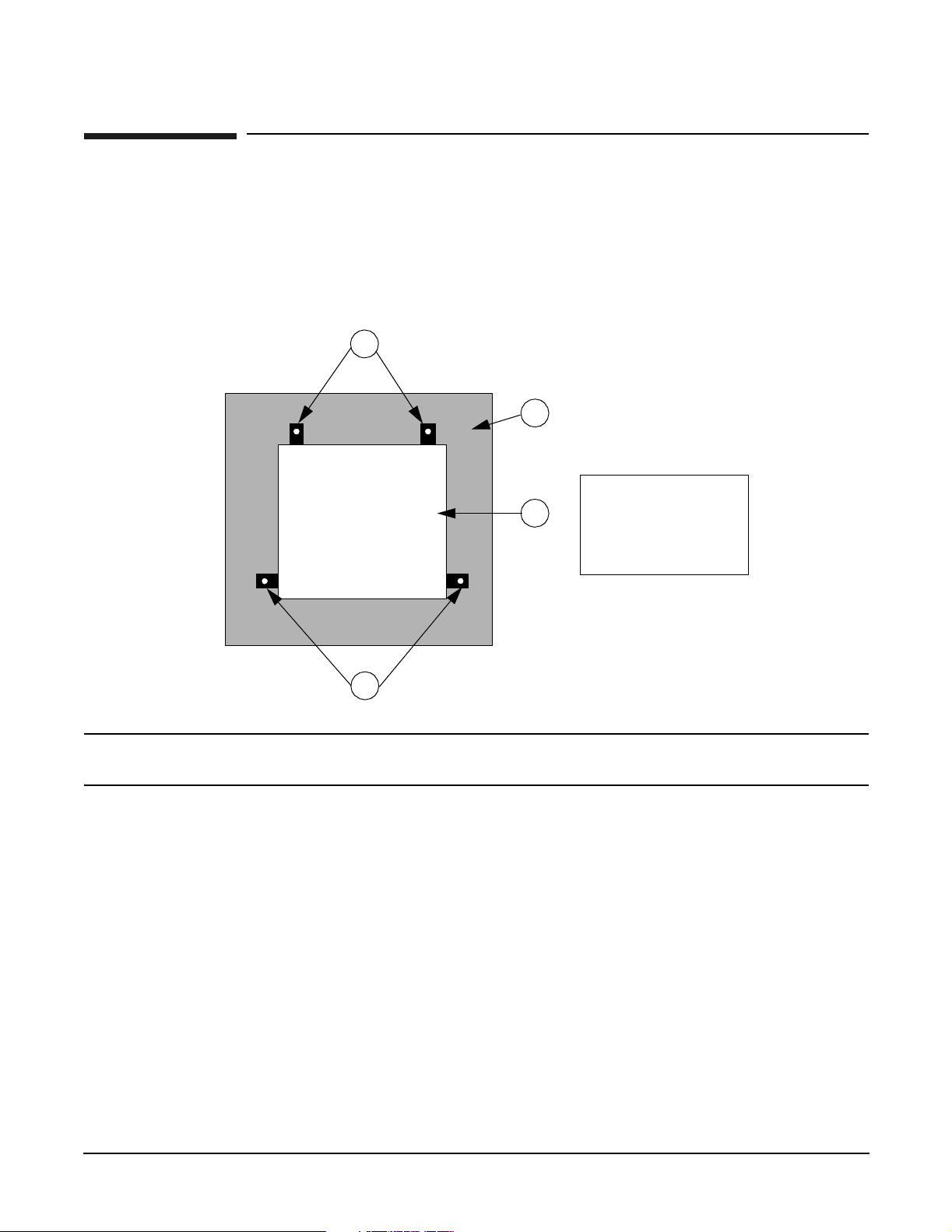
1. Carefully remove the carton and anti-static bag from the pallet.
2. Remove the front two (2) L-brackets. Retain the 1/2-inch bolts for later use.
1
Rear
2
3
Front
1
NOTE As viewed from the front, one bracket is located on each side at the base of the cabinet near
the front.
1. Shipping L-Bracket
2. Shipping Pallet
3. Cabinet (Top View)
4
Chapter 2
Page 19
Server Unpacking and Installation
Factory Integrated rp54xx Cabinet Installation
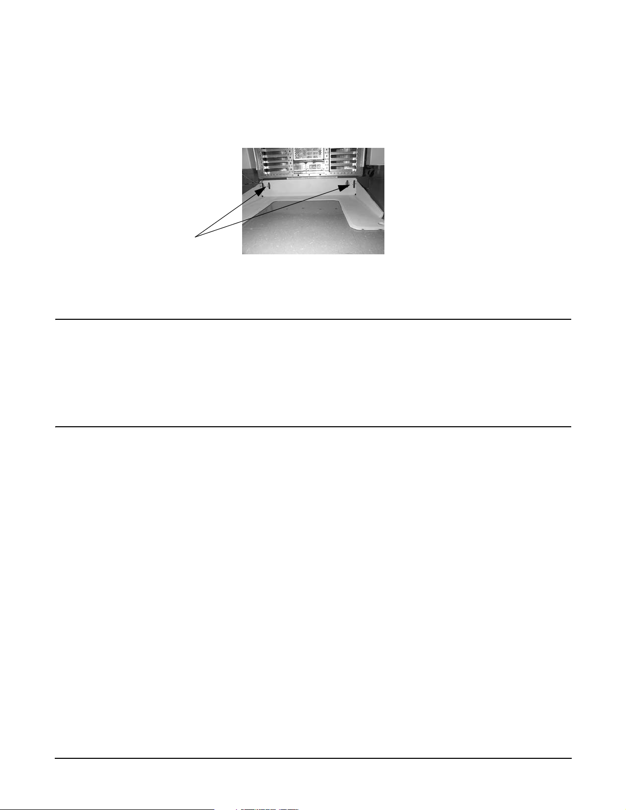
3. At the rear of the cabinet:
a. Open the door.
b. Remove the anti-tip foot by removing and retaining the two (2) 1/2-inch bolts.
For Shipping:
L-brackets are
mounted behind
anti-tip foot.
Same bolts
secure both.
Bolts
c. Remove the two (2) L-brackets (revealed by removing the anti-tip foot).
4. Remove the two ramps from the pallet and carefully place them into the slots at the front of the pallet.
WARNING Use extreme care when rolling the racked system down the ramps. A rack
containing one rp54xx can weigh up to 418 lbs. Do not stand in front of the ramps
when rolling the cabinet off the pallet or injury may occur. All but the smallest
configurations require two persons to safely remove the rack from the pallet.
If anti-tip feet or ballast are not installed or are improperly installed the cabinet
can tip. Failure to follow this precaution can cause injury to personnel or damage
to equipment.
Chapter 2
5
Page 20
Server Unpacking and Installation
Factory Integrated rp54xx Cabinet Installation
5. Straighten the rollers on the cabinet base, if needed, and carefully roll it down the ramps.
WARNING After removing the server from the pallet, Do not move the cabinet unless the
anti-tip feet are installed! The cabinet can tip if care is not used. Due to their low
ground clearance the feet may catch on irregularities on the floor, thresholds, or
ramps.
Do not move the cabinet without first installing the anti-tip feet. The cabinet may
tip if moved without the anti-tip feet or ballast installed.
Do not move the cabinet after installing the anti-tip feet unless they are in the
fully-raised position. Once installed, the anti-tip feet must be fully raised to allow
ground clearance.
Because of their low ground clearance, the fully-raised anti-tip feet may need to
be removed temporarily to clear some obstacles such as door jambs, ramps, and
other large irregularities or obstructions on the floor.
If you must temporarily remove the anti-tip feet to clear an obstacle, use extreme
caution when moving the cabinet. Always reinstall the anti-tip feet as soon as the
obstacle has been cleared.
Lower and secure both the anti-tip feet and the cabinet leveling/stabilizer feet
once the cabinet is in place.
Failure to follow these precautions can result in equipment damage or personal
injury.
6. Install the front and rear anti-tip feet using the 1/2 inch bolts provided. Ensure that the anti-tip feet are
installed in the fully up position in the mounting slots. This will provide maximum ground clearance
while moving the cabinet to its final position.
7. Carefully move the cabinet to its installation location.
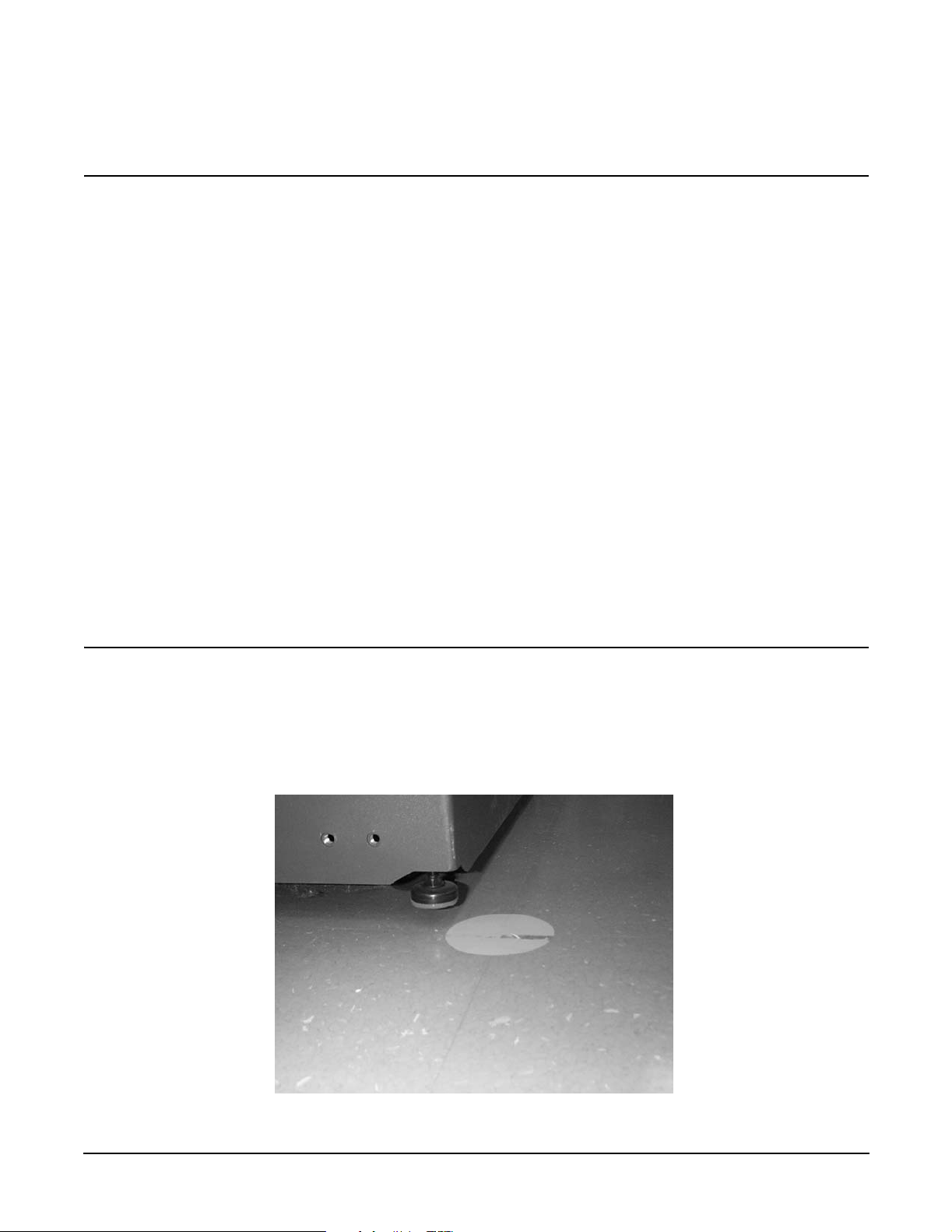
8. Lower the anti-tip feet to the fully down position and adjust the cabinet leveling feet for best cabinet
stability.
6
Chapter 2
Page 21
Server Unpacking and Installation
Receive and Unpack A Non-Integrated Server
Receive and Unpack A Non-Integrated Server
WARNING The typical rp54xx system can weigh up to 68kg (150lbs). HP recommends using an
an approved lifting device. Lift and move the server in accordance with all local
safety regulations. Failure to follow this precaution can cause injury to personnel or
damage to equipment.
Unpacking the server
The following procedure describes the steps involved in unpacking the server, whether to function as a
stand-alone Deskside unit, or to be integrated into a cabinet.
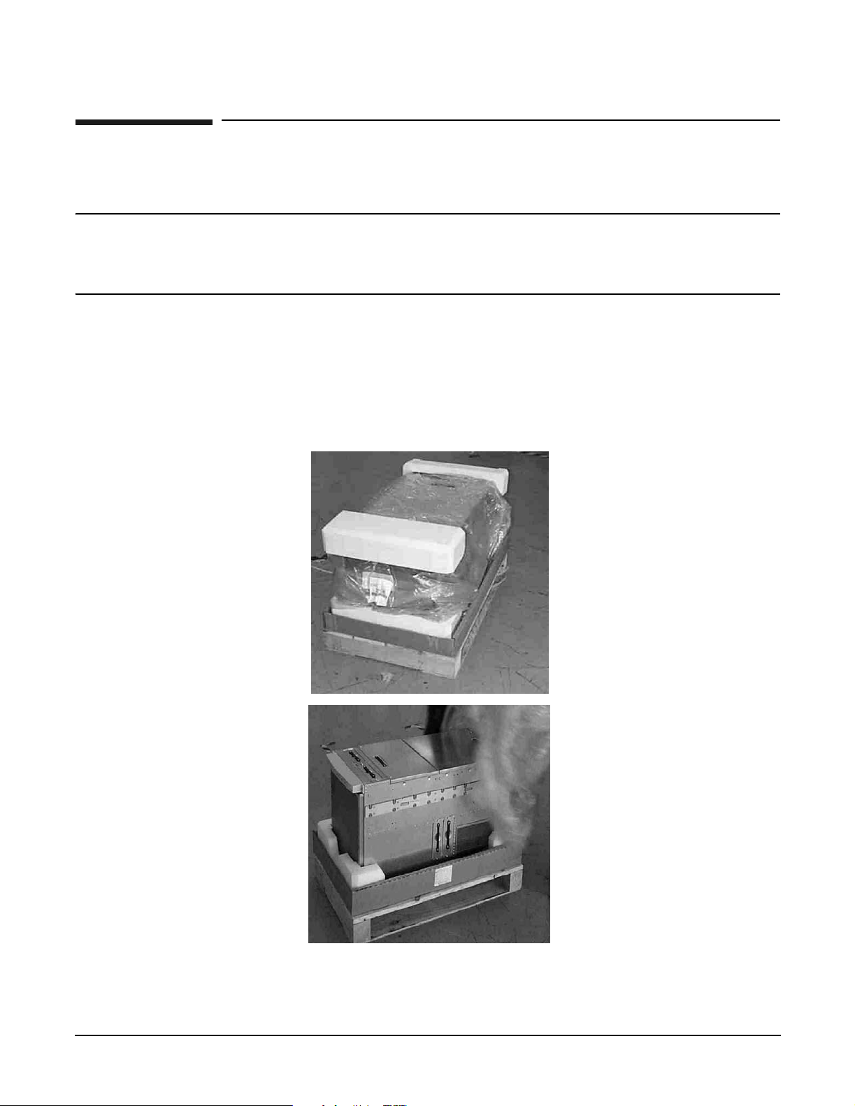
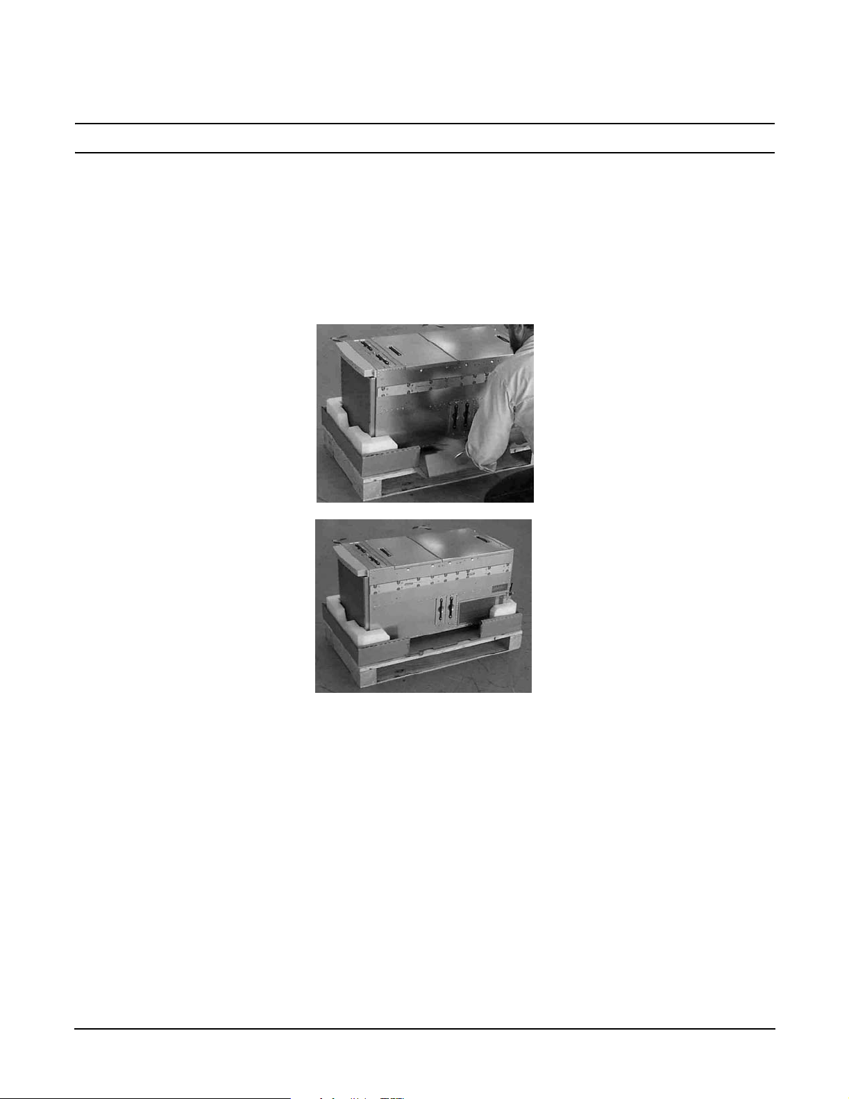
Step 1. Remove the shipping carton and anti-static bag from the server as depicted below.
Chapter 2
7
Page 22
Server Unpacking and Installation
Receive and Unpack A Non-Integrated Server
NOTE The packaging for rp74xx and rp54xx servers is the same, rp74xx is shown.
Step 2. If you are moving the server manually, use three people to lift the server from the packing material
and pallet. Carefully move the server to the selected location.
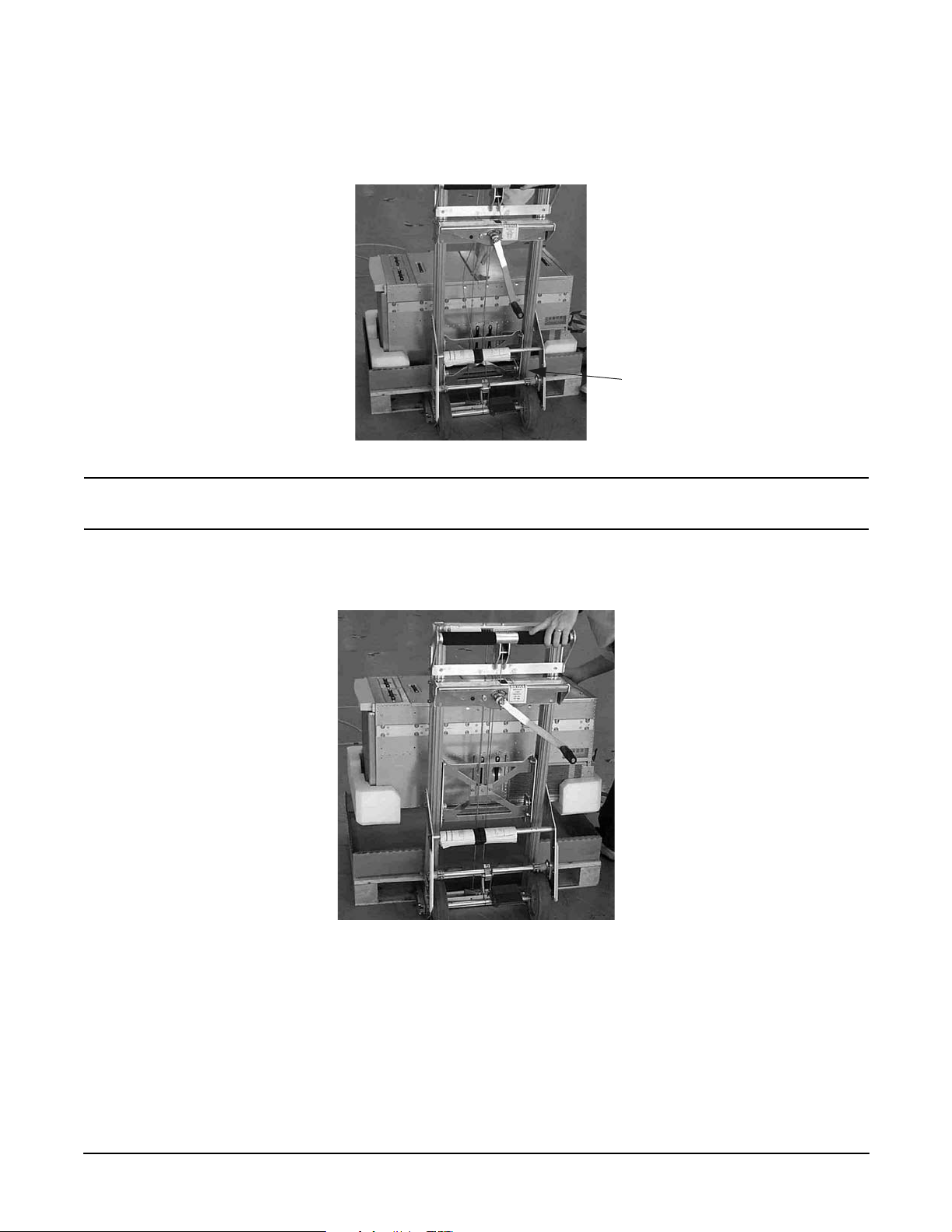
Step 3. If you are moving the server by an approved lifting device (such as Genie Lift ), remove the tear
flap from the front lip of the carton bottom to allow access to the server, as illustrated below.
Removal of the tear flap will reveal a slot between the bottom of the server and the inside bottom of
the cardboard box.
8
Chapter 2
Page 23
Server Unpacking and Installation
Receive and Unpack A Non-Integrated Server
Step 4. Carefully raise the lift’s platform so that it will slide into the slot located under the center of the
server, but over the top of the pallet.
Lifting Device
Platform.
NOTE The server’s center of gravity will vary with the hardware configuration, but it is
generally located slightly behind the middle of the server.
Step 5. Raise the lifting device platform enough for the server to clear the pallet and packing materials, as
show below.
Chapter 2
9
Page 24
Server Unpacking and Installation
Install Deskside Server
Install Deskside Server
The following section describes the installation of a server into a Deskside enclosure for installation in an
office environment.
WARNING The typical rp54xx system can weigh up to 68kg (150lbs). HP recommends using an
approved lifting device.
• Lift and move the server in accordance with all local safety regulations.
• Do not attempt to lift the server by the plastic handles on the top and side covers.
Failure to follow these precautions can cause injury to personnel or damage to
equipment.
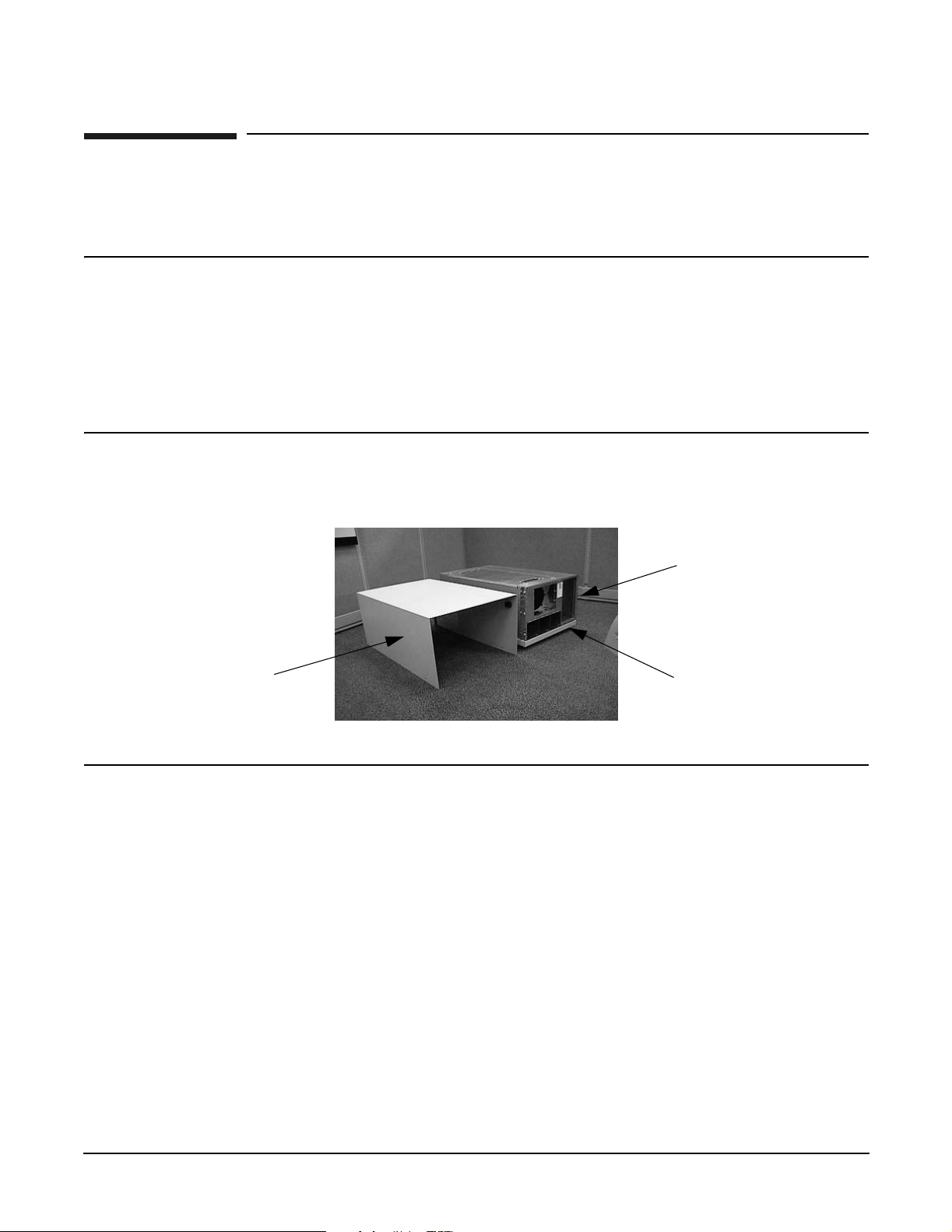
Step 1. Unpack the server.
Step 2. Unpack the deskside enclosure.
Server
Enclosure
Outside
Cover
(Skin)
NOTE Ensure that the positioning spring pins in the enclosure base align with the
alignment holes in the bottom of the server.
Wheeled
Enclosure
Base
10
Chapter 2
Page 25
Server Unpacking and Installation
Install Deskside Server
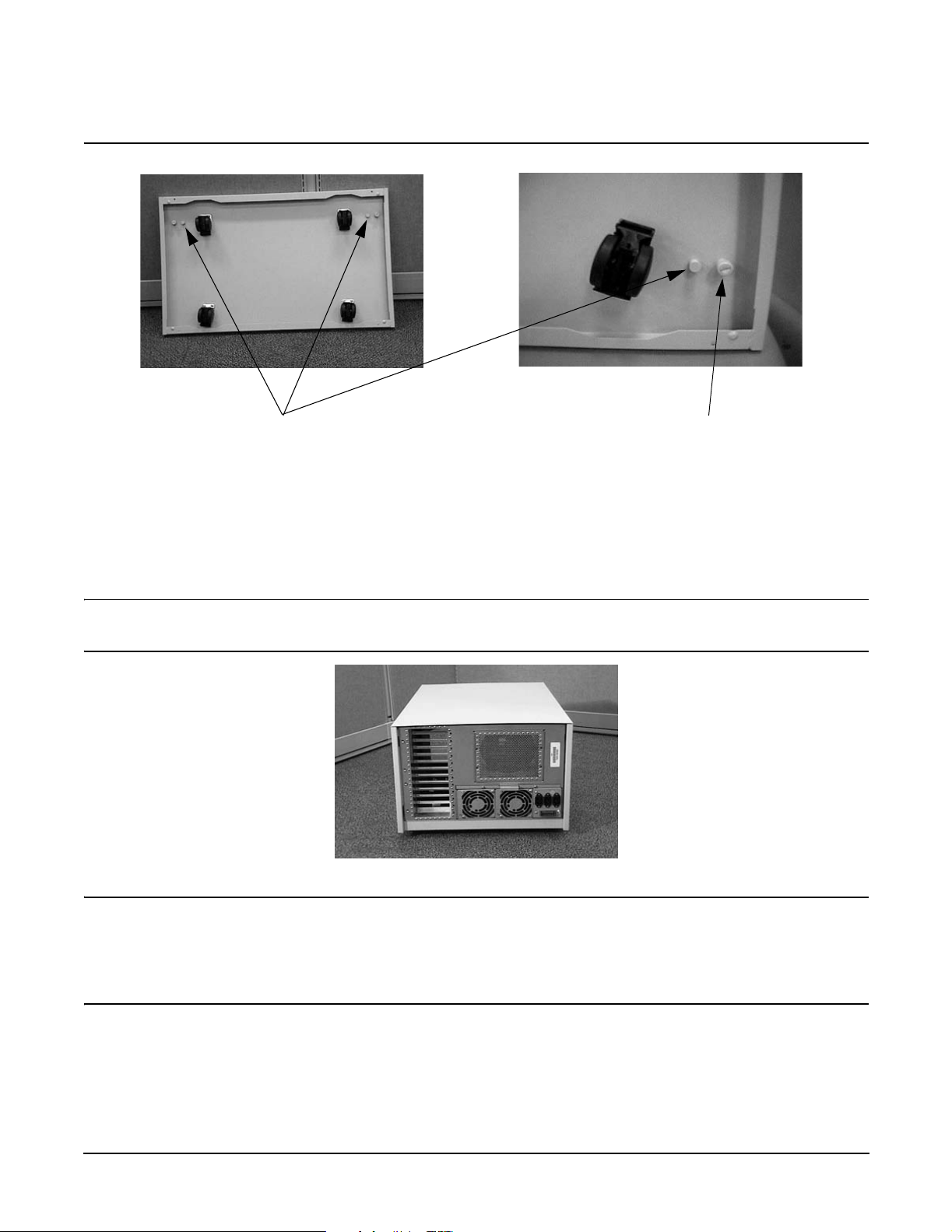
Alignment Spring Pins
Captive Fastener
Step 3. Position the server on the wheeled enclosure base.
Step 4. Tighten the two captive screws in the enclosure base to secure the server to the base.
Step 5. Position the enclosure cover (outside skin) over the server and install and tighten the screws to
secure it to the base.
NOTE The perforations and the lip of the outside skin should be toward the rear of the
server.
WARNING Stacking rp54xx servers in deskside enclosures is not supported.
Stacking rp54xx servers in deskside enclosures can damage equipment,
may cause injury to personnel, and may void your warranty or service
contract.
Step 6. Install the Front Bezel.
Step 7. Locate the two pull-tabs. One pull-tab is longer than the other. The shorter pull-tab is blank on both
sides. The back of the shorter pull-tab provides a writable surface for Customer use.
Chapter 2
11
Page 26
Server Unpacking and Installation
Install Deskside Server
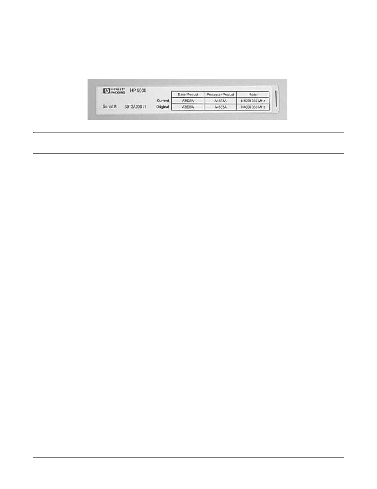
Step 8. Locate the plastic bag containing the label sheet (taped to the server).
Step 9. Remove the label containing serial number, base product, processor product, and model information
from the label sheet and apply to the back of the longer pull-tab.
NOTE Pull-tab and label shown above is for an rp74xx server. rp54xx uses the same style
label and similar pull-tab.
Step 10. Insert the pull-tabs into the front bezel. Install the longer pull-tab in the left side plastic window in
such a way that the rp54xx logo is visible. Install the shorter pull-tab in the right side plastic
window with either surface visible. Refer to the diagram above for pull-tab locations.
12
Chapter 2
Page 27
Server Unpacking and Installation
Install Stand-Alone Server in a Cabinet
Install Stand-Alone Server in a Cabinet
The following describes how to install the A5556A slide-tray assembly into an approved HP cabinet in
preparation for installing an rp54xx server.
This slide-tray assembly can be installed in an HP E-Series cabinet or other HP cabinets approved for rp54xx
system installation. To install the A5556A slide-tray assembly in an approved HP equipment cabinet, proceed
as follows:
Step 1. Determine what type of cabinet you are installing the slide-tray assembly into.
a. E-Series cabinets have:
• Parchment white, plastic, sectional, side panels
• Black painted vertical frame posts with a partial return flange.
b. Approved, non-E-Series, cabinets have:
• Single piece metal side panels
• Gray painted verticle frame posts with full return flanges.
Vert ica l ,
Rectangular,
Mounting Slots
Vertica l,
Rectangular,
Mounting Slots
Step 2. Note the vertical, rectangular, slots in the return flanges on the vertical mounting posts. Determine
into which of these vertical slots the slide/tray kit will be installed. This is done by counting down
eight rectangular slots from the top of the cabinet or the bottom of the equipment above.
Chapter 2
13
Page 28
Server Unpacking and Installation
Install Stand-Alone Server in a Cabinet
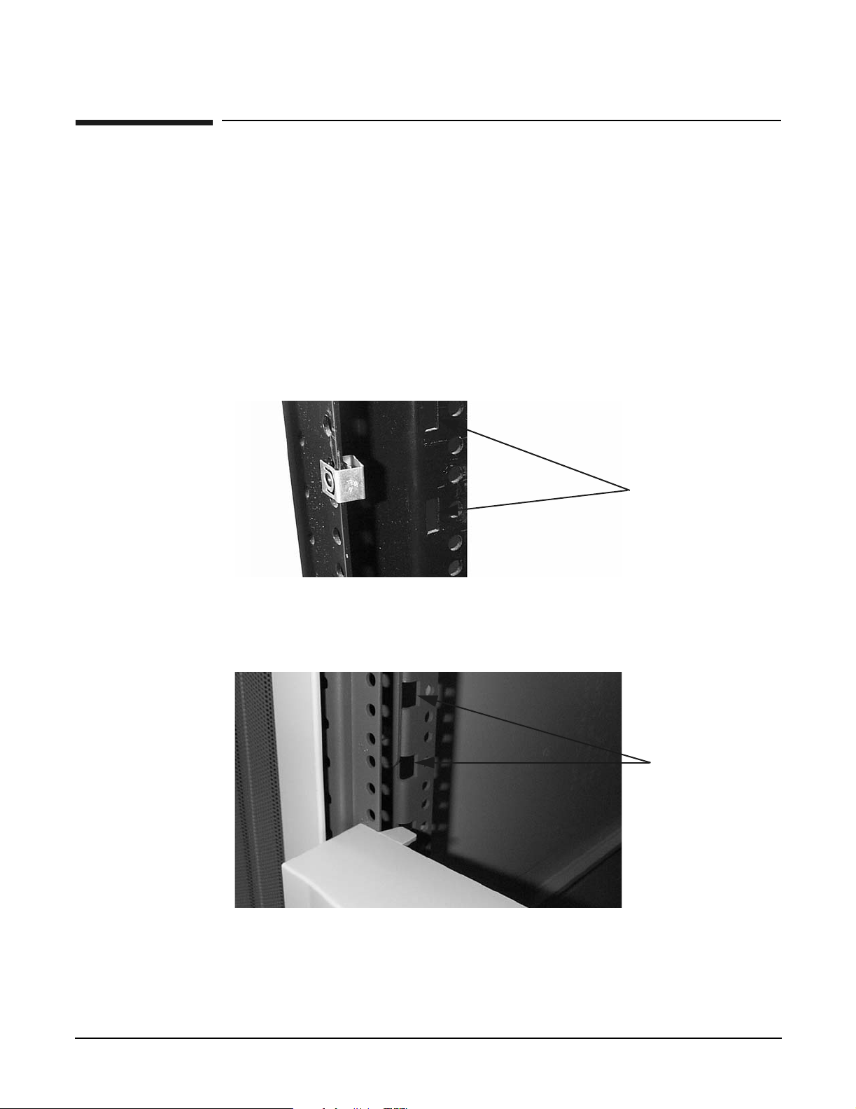
Step 3. On the front vertical mounting posts only, slide M5 sheet metal nuts onto the posts over the holes
immediately adjacent to the vertical slots determined in the previous step. Also place M5 sheet
metal nuts on the holes directly above these. Orient the sheet metal nuts so that the threaded
portion faces towards the outside of the cabinet. There should now be a total of four (4) sheet metal
nuts installed.
Step 4. If the cabinet is a non-E-Series cabinet, discard the left hand and right hand aluminum spacers and
two of the M5 x 16 screws with cress-cup washers and proceed to step 12.
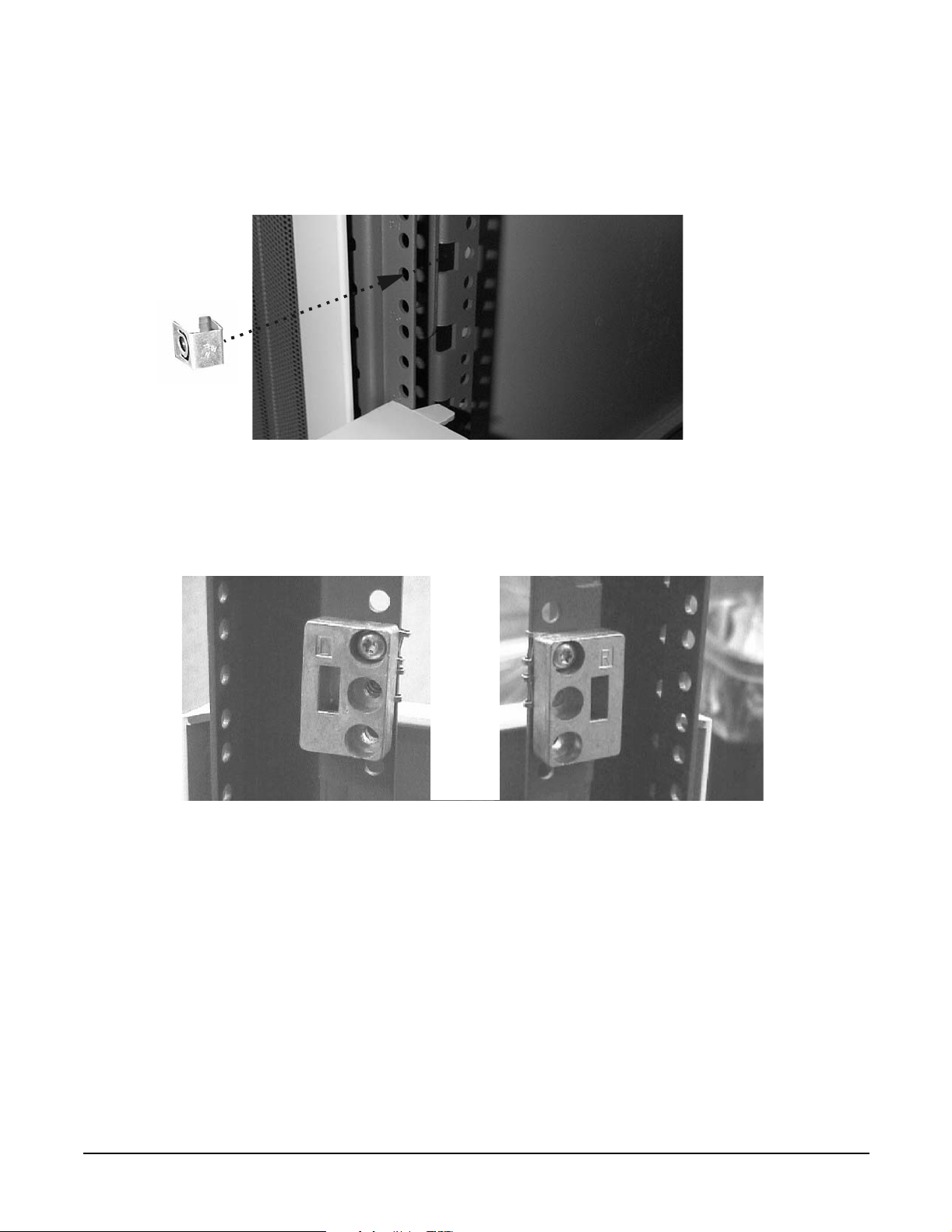
Step 5. If the cabinet is an E-Series cabinet, place the hook of the aluminum spacer marked “L” (5183-1864)
into the appropriate vertical, rectangular slot on the front, left hand mounting post. The hook
points downward. Similarly, place the spacer marked “R” (5183-1863) into the appropriate slot on
the right hand mounting post.
Step 6. Use one M5 x 16 screw with cress-cup washer to attach each spacer to its vertical post. Do this by
inserting the screw through the top hole in the spacer, through the mounting rail and tightening it
into the sheet metal nut located at that position.
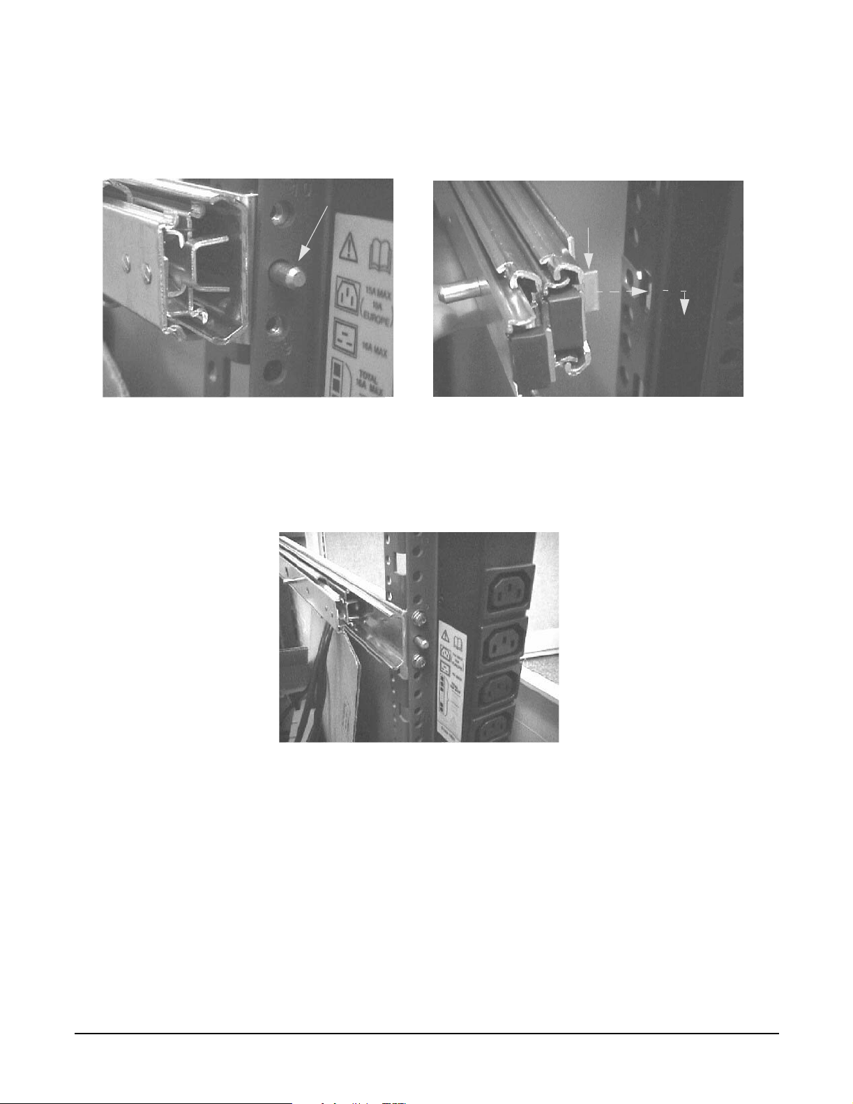
Step 7. Take the left hand slide/bracket assembly (marked 337079-1L) and install it into the left hand
vertical mounting posts. This is done by inserting the pin at the rear of the slide's mounting bracket
into the 23rd hole in the rear vertical mounting post and inserting the hook at the front of the
14
Chapter 2
Page 29
Server Unpacking and Installation
Install Stand-Alone Server in a Cabinet
bracket into the vertical, rectangular slot in the aluminum spacer. The slide should be positioned in
the cabinet so that it is horizontal and level.
Guide Pin
Hook
Step 8. Securely fasten the rear of the slide's mounting bracket to the rear vertical mounting post by
installing and tightening two of the M5 x 16 screws with cress-cup washers thorough the mounting
post, through the slides mounting bracket and into the threaded nuts attached to the mounting
bracket.
Chapter 2
15
Page 30
Server Unpacking and Installation
Install Stand-Alone Server in a Cabinet
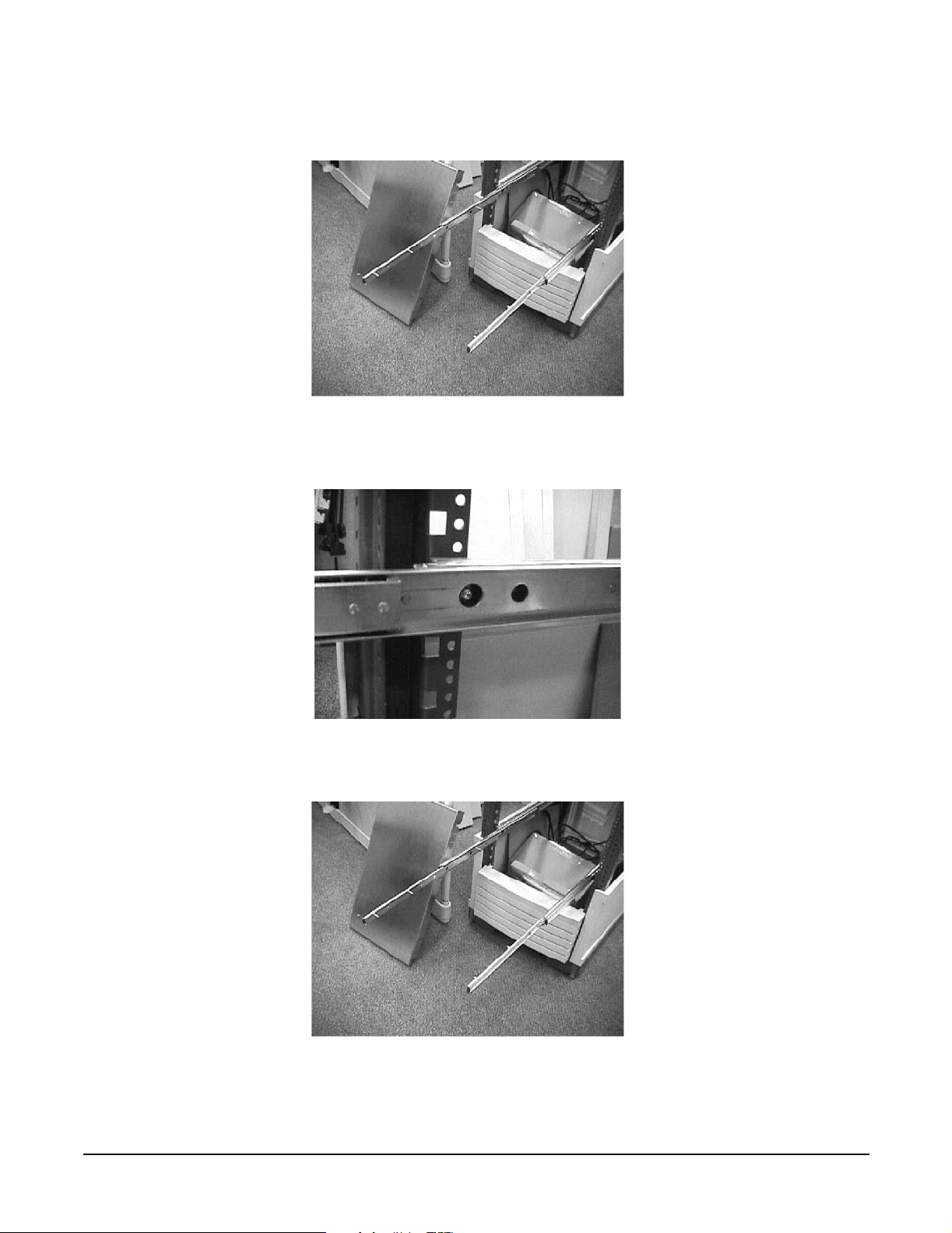
Step 9. Fully extend the slide so that it is locked in the fully open position.
Step 10. Use an M5 x 30 screw with a cress cup washer to attach the front of the slide to the vertical
mounting post. Insert the screw through the slide, through the center hole of the aluminum spacer,
through the vertical mounting post, and tighten into the sheet metal nut located at that position.
Step 11. Use a procedure similar to steps 7 through 10 to install the right hand slide/bracket assembly
(marked 337079-1R) and then proceed to step 12.
16
Chapter 2
Page 31

Server Unpacking and Installation
Install Stand-Alone Server in a Cabinet
Step 12. Take the tray and place it onto the pins that extend from the slides' inner members. The slots with
wide lead-in guides on the side of the tray fit down onto the slides' pins. The flat part of the tray will
be on top, and the mounting holes in the top of the tray will be located to the right of the center of
the tray. Slide the tray all the way down on both sides so that the pins reach the top of the slots in
the side of the tray.
Pins in Slots
Step 13. Use six, M5 x 12 screws (without washers) to attach the tray to the slides. Three screws are used to
attach each slide. Insert the screws through the slides, through the tray and tighten into the
threaded nuts located on the inside of the sides of the tray.
3 Pan Head
M5x12 T25 screws
on each side
Step 14. From the bottom of the tray pull the plunger pin down and give it a 1/4 turn to hold it in place.
Chapter 2
17
Page 32

Server Unpacking and Installation
Install Stand-Alone Server in a Cabinet
Step 15. Position the server on the tray aligning the plunger pins with the alignment holes in the chassis.
Step 16. Release the plunger pins to secure the server.
18
Chapter 2
Page 33

Server Unpacking and Installation
Stationary L-Bracket Rail Assembly
Stationary L-Bracket Rail Assembly
rp54xx servers may be installed into E-Series and approved Non- E-Series cabinets using stationary
L-bracket rail assembly kits listed below.
NOTE rp54xx servers are supported in Hewlett-Packard E-series and approved Non- E-series
Hewlett-Packard cabinets, and approved rail kits.
For information on additional qualified 3rd party cabinets and rail kits, contact the nearest
Hewlett-Packard Response Center.
Cabinet Type Rail Kit Product Number
E-Series HP Cabinet A5575A
Other Approved HP Cabinet A5562A
Identifying Approved Non-E-Series HP Cabinets
Approved Non- E-Series cabinets have black frames, one piece outside sheet metal skins, a partial return
flange, and requires the installation of the aluminum spacer blocks, supplied with the rail kits.
Approved Non- E-Series cabinets include the following product numbers: A1883A, A1884A, A1896A, A1897A,
C1897A, C2785A, C2786A, and C2787A.
Chapter 2
19
Page 34

Server Unpacking and Installation
Stationary L-Bracket Rail Assembly
Identifying E-Series HP Cabinets
E-Series cabinets have light gray frames, sectioned, plastic outside “skins”, a full return flange, and does not
require the installation of the aluminum spacer block supplied, with the rail kits.
E-Series cabinets include the following product numbers: A5134A, A5136A, A5136A, A4900A, A4901A,
A4902A, J1500A, J1502A, and J1502A.
Identifying Static Rail Kit
Hewlett-Packard has currently approved two static rail kits for use in cabinet mounting the rp54xx server.
They are illustrated below.
20
A5575A Kit RailA5562A Kit Rail
Chapter 2
Page 35

Server Unpacking and Installation
Stationary L-Bracket Rail Assembly
Installing Stationary Rails
The installation of stationary rails is similar for most cabinet and rail combinations.
The key considerations to are:
• Ensure that all safety precautions are read, understood, and observed
• Follow all installation instructions provided with the cabinet and rail kits, and
• Ensure that the rails extend out from the cabinet posts sufficiently to properly and safely support the
equipment being installed.
To install an rp54xx server on stationary rails in an approved cabinet proceed as follows:
Step 1. Locate the rail mounting height in the cabinet. Allow for the following space requirements:
• For each rp54xx server, allow 31.8cm (12.5 inches) vertically (7 EIAs or Rack Units (RUs).
• If installing the A5575A rail kit, allow an additional vertical 4.45cm (1.75 inches (1 EIA) each
set of rails.
31.8 cm
(12.5
inches
4.45 cm
(1.75
Inches
Step 2. Install sheet metal nut(s) in the vertical cabinet posts at the required height for the kit being
installed:
• Install the first nut either:
rp54xx
Server
Rail
rp54xx
Server
Rail
31.8 cm
(14.25
inches
A5575A Rail Kit
in approved
Non- E-Series
cabinet shown
— 4.45 cm (1.75 Inches) above the top, or
— 31.8 cm (12.5 inches) below the bottom of the last server.
• If installing a A5562A rail kit, install the second nut in the next frame hole below the first.
Step 3. Hold the rail in place and insert and tighten the screws.
Chapter 2
21
Page 36

Server Unpacking and Installation
Stationary L-Bracket Rail Assembly
For installation of other qualified cabinet and rail combinations refer to the safety precautions and
instructions accompanying them.
22
Chapter 2
Page 37

3 Installing Additional Components
Chapter 3
23
Page 38

Installing Additional Components
Additional Components
Additional Components
Some internal components are too delicate to be installed in the server prior to shipping. These internal
components are shipped with the server, but are packed separately. They can be installed after the cabinet
has been unpacked and positioned.
Some of the internal components that are packed separately are not user-installable. To maintain warranty
validation, these items must be installed by a Hewlett-Packard Customer Engineer.
If you received either (or both) of the components listed below, contact your Hewlett-Packard provider to
arrange for installation.
• Central Processing Units (CPUs)
• Power Distribution Units (PDUs)
24
Chapter 3
Page 39

Installing Additional Components
Installing Memory
Installing Memory
Memory Configuration Rules
rp54xx servers have 16 slots (8 DIMM pairs) for memory DIMMs. These slots are numbered 0a/b, 1a/b,... 7a/b.
8 of these slots (4a/b - 7a/b) are disabled on rp5400 servers. rp5450 servers can access all slots. rp5400 and
rp5450 servers have DIMM slots located on the System Board.
rp5470 servers install DIMMs using Memory Carriers. The Memory Carriers fit into slots on the System
Board.
The following rules govern the installation of memory DIMMs for rp5400, rp5450, and rp5470 servers:
• Memory must be installed in DIMM pairs.
• The capacity of DIMMs within a pair must be the same.
• Install DIMMs with the greatest capacity in the lowest slot numbers.
• Install DIMMs the following slot order: 0a/b, 1a/b, 2a/b, 3a/b, and so on.
Installing rp5400 and/or rp5450 DIMMs
Step 1. Power down and unplug the rp54xx server.
CAUTION DC voltages are present when the server is connected to AC power. Do not install or
service rp54xx internal components while DC voltage is present. Failure to observe
this precaution can result in damage to the server.
Step 2. Loosen the captive T-15 screws that hold the top cover in place, then grasp the strap handle, raise
the cover slightly, and pull the cover toward the front of the server to free the cover tabs from the
slots in the chassis. The air baffle will be exposed.
Step 3. Make the top of the server accessible for service.
Chapter 3
25
Page 40

Installing Additional Components
Installing Memory
Step 4. Loosen the captive T-15 screws on the air baffle. Grasp the two handles on the baffle, and lift the
baffle remove it.
CAUTION Observe all ElectroStatic Discharge (ESD) precautions Do not touch internal
components. Failure to observe ESD precautions can cause damage to components.
Step 5. Observe Electrostatic Discharge (ESD) precautions.
Step 6. Refer to the following graphic for memory slot locations.
26
Chapter 3
Page 41

Installing Additional Components
Installing Memory
Locate the correct DIMM pair slots. Insert the DIMM connectors into the guides until the card
snaps firmly in place. It may be necessary to apply downward force using the palm of your hand on
the DIMM. Observe the top of the DIMM to make sure one side is not higher than the other.
NOTE It may be necessary to remove PSM 1 when installing a DIMM in slot 0a and PSM 0
when installing a DIMM in slot 1b. If either PSM is removed to install memory,
ensure it is re-installed.
Step 7. Replace the air baffle. Tighten the four captive screws to secure the air baffle in place.
Step 8. Replace the top cover. Tighten the four captive screws to secure the top cover in place.
Step 9. For rack configurations, insert the rp54xx server back into the rack.
Step 10. For deskside enclosure configurations, replace the deskside enclosure cover.
Step 11. Power the rp54xx server on.
Step 12. Use the BCH command in me to verify the system recognizes the memory that you have just
added.
Chapter 3
27
Page 42

Installing Additional Components
Installing Memory
Installing rp5470 DIMMs
DIMMs for the rp5470 system are installed in memory carriers instead of the system board, as are the other
rp54xx systems. However, rp5470 memory carriers are also located on the system board, so the method for
opening and closing the system is the same. Procedures for removing and replacing the server top and baffle
are listed below, without the pictures shown in the section titled, “Installing rp5400 and/or rp5450 DIMMs.”
If you wish to reveiw the pictures, please refer to the aforementioned section.
Step 1. Power down and unplug the rp54xx server.
NOTE DC voltages are present when the server is connected to AC power. Do not attempt to
install or service: CPUs, Memory, PSMs, the Platform Monitor or PCI I/O cards
installed in non-Turbo slots (1-6) while DC voltage is present. Failure to observe this
warning may result in damage to the server.
Step 2. Make the top of the server accessible for service.
Step 3. Loosen the captive T-15 screws that hold the top cover in place, then grasp the strap handle, raise
the cover slightly, and pull the cover toward the front of the server to free the cover tabs from the
slots in the chassis. The air baffle will be exposed.
Step 4. Loosen the four (4) captive T-15 screws on the air baffle. Grasp the two handles on the baffle, and
lift and remove the baffle.
Step 5. Observe Electrostatic Discharge (ESD) precautions.
Step 6. Refer to the following graphic for Memory Carrier locations.
MemoryCarrier Assemblies
28
Chapter 3
Page 43

Installing Additional Components
Installing Memory
a. Locate the Memory Carrier and pull up on the extractor levers on each end of the Memory
Carrier to unseat the Memory Carrier from its socket.
b. When the Memory Carrier unseats from the socket, pull it away from the System Board.
c. Loosen the captive screws that secure the DIMM Clip and remove the DIMM Clip from the
Memory Carrier.
d. Seat the memory DIMM into its socket on the Memory Carrier.
e. Press the extractor levers on each end of the memory DIMM slot inward until the levers snap
into place.
f. Attach the Memory Clip to the Memory Carrier with the DIMM slot markings on the top of the
Memory Clip aligned with the DIMM slot markings on the Memory Carrier.
g. Secure the Memory Clip using the captive screws.
h. Seat the Memory Carrier into the appropriate slot on the System Board.
i. Push down on the extractor levers and snap them into place.
Step 7. Replace the air baffle. Tighten the four captive screws to secure the air baffle in place.
Step 8. Replace the top cover. Slide the cover tabs into the slots in the chassis and close the cover. Tighten
the two captive screws to secure the top cover in place.
Step 9. For rack configurations, insert the rp54xx server back into the rack.
Step 10. For deskside enclosure configurations, replace the deskside enclosure cover.
Step 11. Power the rp54xx server on.
Step 12. Use the BCH command in me to verify the system recognizes the memory that you have just
added.
Chapter 3
29
Page 44

Installing Additional Components
Installing Peripheral Component Interconnect (PCI) Cards
Installing Peripheral Component Interconnect (PCI) Cards
rp54xx servers have a total of 12 PCI I/O slots. Slots 1 and 2 are reserved for the LAN/SCSI and GSP Core I/O
cards, leaving 10 PCI I/O slots available for Customer use.
rp5400/rp5450 PCI Card Slots
For rp5400 and rp5450 models, 10 PCI I/O slots consist of Turbo and non-Turbo slots. Server PCI slots are
shown below.
rp5400/rp5450 PCI Card Slots
• Slots 1 and 2 are reserved for the rp54xx LAN/SCSI and GSP (Guardian Service Processor) Core I/O
cards, respectively. Slots 1 and 2 are non-Turbo slots. Non-Turbo slots share a single 250MB/s PCI bus
and are incapable of HotPlug functionality. The server must be turned off prior to removing or installing
the LAN/SCSI or GSP cards in these slots.
• Slots 3 - 6 are non-Turbo slots. These four Non-Turbo slots share a single 250MB/s PCI bus, run at 33MHz
and support 32 and 64-bit PCI cards. Non-Turbo slots are incapable of HotPlug functionality. The server
must be turned off prior to removing or installing PCI cards in these slots.
• Slots 7 - 12 are Turbo slots. Each Turbo slot has a dedicated 250MB/s PCI bus, run at 66MHz and support
32 and 64-bit PCI cards. Turbo slots are HotPlug capable. Below each Turbo slot is a plastic PCI card
separator. The PCI card separator has two LEDs and a pull tab on the outer edge. The LED’s provide
power and status for the slot. The pull tab allows the PCI card to be easily removed.
rp5400 servers have access to slots 1, 2 and 8-12 while rp5450 servers have access to all (1-12) slots.
NOTE Slot 3 will become enabled on rp5400 servers with server firmware versions later than 40.48.
A slot 3 enabled label (A5576-84009) is available for rp5400 systems.
30
Chapter 3
Page 45

Installing Additional Components
Installing Peripheral Component Interconnect (PCI) Cards
rp5470 PCI Card Slots
For rp5470 models, the 10 PCI I/O slots consist of Twin Turbo, Turbo, and non-Turbo slots. The following
illustration shows the PCI card slot layout.
rp5470 PCI Slots
• Slots 1 and 2 are reserved for the rp54xx LAN/SCSI and GSP (Guardian Service Processor) Core I/O
cards, respectively. Slots 1 and 2 are non-Turbo slots. Non-Turbo slots share a single 250MB/s PCI bus
and are incapable of HotPlug functionality. The server must be turned off prior to removing or installing
the LAN/SCSI or GSP cards in these slots.
• Slots 3 and 4 are non-Turbo slots. These two Non-Turbo slots share a single 250MB/s PCI bus, run at
33MHz and support 32 and 64-bit PCI cards. Non-Turbo slots are incapable of HotPlug functionality. The
server must be turned off prior to removing or installing PCI cards in these slots.
• Slots 5 - 10 are Turbo slots. Each Turbo slot has a dedicated 250MB/s PCI bus, run at 66MHz and support
32 and 64-bit PCI cards. Turbo slots are HotPlug capable. Below each Turbo slot is a plastic PCI card
separator. The PCI card separator has two LEDs and a pull tab on the outer edge. The LED’s provide
power and status for the slot. The pull tab allows the PCI card to be easily removed.
• Slots 11 and 12 are Twin Turbo slots. Each Twin Turbo slot has a dedicated 500MB/S PCI bus, runs at 66
MHz, and supports 32- and 64-bit PCI cards. Twin Turbo slots are HotPlug capable. Below each Twin
Turbo slot is a plastic PCI card separator. The PCI card separator has two LEDs and a pull tab on the
outer edge. The LED’s provide power and status for the slot and the pull tab allows the PCI card to be
easily removed.
rp5470 servers have access to all (1-12) slots.
Chapter 3
31
Page 46

Installing Additional Components
Installing Peripheral Component Interconnect (PCI) Cards
PCI I/O Card Installation Restrictions
Restrictions apply regarding the installation of PCI I/O cards which contain a PCI-to-PCI bridge:
• HP-UX boot is currently not supported for cards that contain a PCI-to-PCI bridge.
• HP-UX patches are required when more than one card containing a PCI-to-PCI bridge is installed in
non-Turbo slots.
PCI I/O Card Installation Order
The following table shows a standard factory PCI card installation that begins with slot 12. Use this table as
a guideline for installing PCI I/O cards in the field.
NOTE A system shipped from the factory may have a different configuration than the same system
built in the field. For example: The factory will install the graphics card in slot 12 and add
other cards below. In the field, slot 12 may already be occupied by another PCI card. It is
acceptable for the graphics card to be installed in any available Turbo slot.
Product
Number
A6150A Graphics, Graphics Card 1 No 1 A4982-66501 3,8
A5838A Combo No 3 A5838-60001 9
A5483A ATM 622Mbps MMF Adapter 10 No 4 A5483-60001 10
A4926A 1000Base SX PCI LAN Adapter 10 No 5 A4926-60001
A4926A 1000Base TX PCI LAN Adapter 10 No 6 A4926-60001
A6092A HYPERFabric No 7 A6092-60001 11
A5158A FC Taclite Y 8 A5846-60001
A5486A Praesidium Speed Card 10 No 9 A5486-60001
A5506A 4 Port 100Base TX LAN Adapter 7/10 No 10 A5506-60101 1,2,6
A5506B 4 Port 100Base TX LAN Adapter 7/10 No 10 A5506-60102
A5150A Dual Port Ultra 2 SCSI adapter 10 Yes 11 A5150-60001 4
A5149A Single Port Ultra 2 SCSI HBA 10 Yes 12 A5149-60001
J3526A High Perf 4 Ports Synchronous Adapter 10 No 13 5063-1322 7,5
Description (all are PCI cards) Max Boot
Load
Order
*
Part
Number
Notes
A4800A FWD SCSI-2 adapter 10 Yes 14 A4800-67002
A5230A 100Base-T LAN Adapter 10 No 15 B5509-66001
A3738A 10/100Base-T LAN Adapter 10 No 16 A3738-60001
A3739A Dual FDDI LAN Adapter 10 No 17 A3739-60001
A5783A Token Ring 4/16/100 Hardware Adapter 10 No 18 A5783-60101
32
Chapter 3
Page 47

Installing Additional Components
Installing Peripheral Component Interconnect (PCI) Cards
Product
Number
Description (all are PCI cards) Max Boot
Load
Order
*
Part
Number
Notes
J3525A Dual Port Synchronous Adapter 10 No 19 J3525-60001
J3593A 64 port Serial MUX system card 10 No 20 J3593-60001
J3592A 8 Port PCI Serial MUX card 4 No 21 J3592-60101
A6150A Graphics, USB Card 1 No 22 A6150-60001
A6150BX Pinnacle 2 Graphics 1 No 1 A6150-60003 12,13
A6386A Hyper Fabric 2 Interconnect 10 No 6 A3686-60001
A5506A Quad Port 10/100B-TX LAN 10 No 10 A5506-60102 14
A6749A 3.3v 64 Port Terminal MUX 10 No 24 A6749-60001
A6748A 3.3v 8 Port Terminal MUX 10 No 25 A6748-60001
*In top down order.
Notes:
1. Card contains a PCI-to-PCI bridge.
2. Requires PHKL_20123, PHKL_20629 and PHNE_19826 or their superseded equivalents.
3. Not supported in non-Turbo slots. Install in Turbo slots only.
4. Requires server firmware revision 39.46 or later.
5. Requires HP-UX 11.1
6. Maximum is 7 for HP-UX versions prior to 11.0. Maximum is 10 for HP-UX version 11.1 and later.
7. Requires PHKL_19543 and PHKL_19544 or their superseded equivalents.
8. Requires HP-UX 11.0 Support Plus (IPR) 0006, June 2000 or later. This product to be released 6/00.
9. Not supported in a shared slot (slots 3-4 for rp5470, slots 3-6 for rp5450, not applicable for rp5400).
10. If you are installing ATM 622 cards in an rp5470 configuration, do not install them in slots 3 and 4
(shared slots).
11. Requires 768 MB for first card and 512 MB for each additional card.
12. Not supported in shared slots.
13. Max of 1. Needs USB card for keyboard and mouse.
14. Contains PCI bridge.
Chapter 3
33
Page 48

Installing Additional Components
Installing Peripheral Component Interconnect (PCI) Cards
Installing a PCI Card
Follow these procedures to install a PCI card.
Step 1. Power down and unplug the rp54xx server.
NOTE DC voltages are present when the server is connected to AC power. Do not attempt to
install or service: CPUs, Memory, PSMs, the Platform Monitor or PCI I/O cards
installed in non-Turbo slots (1-6) while DC voltage is present. Failure to observe this
warning may result in damage to the server.
Step 2. Make the right side of the server accessible for service.
Step 3. Using a Torx 15 screwdriver, loosen the captive screws on the right side panel. This panel has a
label which shows which PCI I/O slots are available and the corresponding paths. The PCI I/O slot
paths for rp5400, rp5450, and rp5470 are shown below.
rp5400 rp5450 rp5430/rp5470
Slot
Slot Type Path Slot/Type Path Slot Type Path
12 Turbo 0/4/0 Turbo 0/4/0 Twin Turbo 0/10/0
11 Turbo 0/7/0 Turbo 0/7/0 Twin Turbo 0/12/0
10 Turbo 0/3/0 Turbo 0/3/0 Turbo 0/8/0
9 Turbo 0/6/0 Turbo 0/6/0 Turbo 0/9/0
8 Turbo 0/2/0 Turbo 0/2/0 Turbo 0/3/0
7 Not Available Turbo 0/5/0
6 Not Available Shared 0/1/0
5 Not Available Shared 0/1/1
4 Not Available Shared 0/1/2
3Not
Available
b
Shared 0/1/3 Shared 0/4/2
Turbo
Turbo
Turbo
Shared
a
a
a
a
0/1/0
0/5/0
0/2/0
0/4/0
2GSP GSP GSP
1 LAN/SCSI LAN/SCSI LAN/SCSI
a. Slot is NOT AVAILABLE for rp5430.
b. Slot 3 becomes available with server firmware versions later than 40.48.
Step 4. Remove the PCI slot cover from the slot that will receive the PCI card. To remove the PCI slot cover,
slide the PCI slot cover away from the server.
34
Chapter 3
Page 49

Installing Additional Components
Installing Peripheral Component Interconnect (PCI) Cards
Step 5. Slide the PCI card connectors into the slot, snapping firmly in place. For full length (cards that
extend to the left side card guides) PCI cards, use the UPPER card guide.
Step 6. At the rear of the chassis, connect the I/O cable to the card just installed.
Step 7. Replace the right side panel and tighten the captive screws.
Step 8. For rack configurations, insert the rp54xx server back into the rack.
Chapter 3
35
Page 50

Installing Additional Components
Installing Peripheral Component Interconnect (PCI) Cards
Step 9. For deskside enclosure configurations, replace the deskside enclosure cover.
Step 10. Power the server on.
Step 11. Use the server firmware in io command to verify the PCI cards are recognized by the server. If
AUTOBOOT is ON, it will be necessary to interrupt the boot process to get to the server firmware
Main Menu: Enter command or menu > prompt.
Step 12. Boot HP-UX and run the ioscan utility to verify the system recognizes the new PCI card.
Online Addition/Replacement (OLA/R) of PCI I/O cards
Beginning with HP-UX 11i (11.11) rp54xx servers support the on-line addition and replacement of PCI I/O
cards. In order for this high availability feature to be fully implemented, the following server requirements
must be met:
• rp5400A/rp5450A firmware must be later than 40.26 (rp5400B/rp5450B/rp5470A firmware will support
OLA/R upon its release).
• HP-UX operating system must be 11i (11.11) or later.
There is a bit that the HP-UX operating system examines to determine if the server hardware and firmware
is capable of OLA/R. This bit is controlled by server firmware. If the bit is ON, OLA/R is possible (when
requirements have been met). The bit was mistakenly set to ON for all rp5400 and rp5450 revision A
(rp5400A and rp5450A) servers. As a result, HP-UX may incorrectly identify these models as being OLA/R
capable. In order to avoid this confusion, verify that the correct level of server firmware is installed.
36
Chapter 3
Page 51

Installing Additional Components
Installing Graphics
Installing Graphics
This section explains how to install rp54xx 2D graphics hardware. For a complete graphics solution, three
products are required. The products listed below are the only products supported on rp54xx servers.
• A6150A rp54xx Graphics Package
— Includes PCI graphics card
— Includes PCI USB (Universal Serial Bus) card
• A4983B Keyboard and Mouse Kit
— Includes mouse with 114” cable
— Includes keyboard with 109” cable
• D8910W (19”) or D2847W (21)” Monitor
— Includes localized power cord and 75” 15-pin video cable
NOTE rp54xx graphics requires HP-UX 11.0 Support Plus (IPR) 0006, June 2000 or later.
The photo below includes the A6150A, A4983B and D8910W products. The video cable for the monitor is not
shown. Black ESD mat not included.
Chapter 3
37
Page 52

Installing Additional Components
Installing Graphics
rp54xx servers have a total of 12 PCI I/O slots. Slots 1 and 2 are reserved for the LAN/SCSI and GSP Core I/O
cards, leaving 10 PCI I/O slots available for Customer use. These 10 PCI I/O slots consist of Turbo and
non-Turbo slots.
rp54xx PCI Slots
• Slots 1 and 2 are reserved for the rp54xx LAN/SCSI and GSP (Guardian Service Processor) Core I/O
cards, respectively. Slots 1 and 2 are non-Turbo slots. Non-Turbo slots share a single 250MB/s PCI bus.
Non-Turbo slots are incapable of HotPlug functionality. The server must be turned off prior to removing
or installing the LAN/SCSI or GSP cards in these slots.
• Slots 3 - 6 are non-Turbo slots. These four Non-Turbo slots share a single 250MB/s PCI bus, run at 33MHz
and support 32 and 64-bit PCI cards. Non-Turbo slots are incapable of HotPlug functionality. The server
must be turned off prior to removing or installing PCI cards in these slots.
• Slots 7 - 12 are Turbo slots. Each Turbo slot has a dedicated 250MB/s PCI bus, run at 66MHz and support
32 and 64-bit PCI cards. Turbo slots are HotPlug capable. Below each Turbo slot is a plastic PCI card
separator. The PCI card separator has two LEDs and a pull tab on the outer edge. The LED’s provide
power and status for the slot. The pull tab allows the PCI card to be easily removed.
rp5400 servers can access PCI slots 1,2 and 8-12. rp5450/3000 servers can access all PCI slots.
Follow these procedures to install graphics cards.
Step 1. Install HP-UX 11.0 Support Plus (IPR) 0006, June 2000 or later. This step ensures the appropriate
HP-UX drivers are installed.
Step 2. Power down and unplug the rp54xx server.
38
Chapter 3
Page 53

Installing Additional Components
Installing Graphics
NOTE DC voltages are present when the server is connected to AC power. Do not attempt to
install or service: CPUs, Memory, PSMs, the Platform Monitor or PCI I/O cards
installed in non-Turbo slots (1-6) while DC voltage is present. Failure to observe this
warning may result in damage to the server.
Step 3. Make the right side of the server accessible for service.
Step 4. Using a Torx 15 screwdriver, loosen the captive screws on the right side panel. This panel has a
label which shows which PCI I/O slots are available and the corresponding paths. The label shown
below is for an rp5400.
Chapter 3
39
Page 54

Installing Additional Components
Installing Graphics
Step 5. Grasp the handle on the right rear panel and remove the panel from the side of the chassis. The 12
PCI slots, numbered 1-12 from bottom to top, will be in view.
Step 6. Remove the PCI slot cover from the slot that will receive the PCI card. To remove the PCI slot cover,
slide the PCI slot cover away from the server.
Step 7. Center the graphics card within the space created by removing the PCI I/O slot cover. Slide the card
toward the edge connectors. Ensure the edge connectors on the card are in alignment with the
connectors of the slot. Apply pressure to the card until it snaps firmly in place. Repeat process for
USB card.
NOTE The graphics card must be installed in any Turbo slot while the USB will work in any
slot. To reserve Turbo slots for high performance I/O cards, install the USB card in a
non-Turbo slot
40
Chapter 3
Page 55

Installing Additional Components
Installing Graphics
Step 8. At the rear of the chassis, connect the keyboard and mouse cables to the USB card. It does not
matter which connector is used for the keyboard or mouse.
Chapter 3
41
Page 56

Installing Additional Components
Installing Graphics
Step 9. Connect one end of the 15-pin video cable connector on the graphics card. This connector is labeled
“Graphics Display” and “Video Out”. Connect the other end of this cable to the graphics monitor.
Step 10. Replace the right side panel and tighten the captive screws.
Step 11. For rack configurations, insert the rp54xx server back into the rack.
Step 12. For deskside enclosure configurations, repalce the deskside enclosure cover.
Step 13. Power the server on.
42
Chapter 3
Page 57

Installing Additional Components
Installing Graphics
Step 14. Use the server firmware in io command to verify the graphics cards are recognized by the server.
If AUTOBOOT is ON, it will be necessary to interrupt the boot process to get to the server firmware
Main Menu: Enter command or menu > prompt.
Step 15. Boot HP-UX and run the ioscan utility to verify the system recognizes the new PCI card.
Step 16. Logon as root and install X/CDE/Motif if not already installed.
Graphics Troubleshooting
This section describes how to troubleshoot common problems encountered during installation or attempted
use of graphics. The following system utilities can be used to display or set the graphics configuration:
• /opt/graphics/common/bin/graphinfo allows you to display the current graphics configuration and the
graphics drivers that are being used.
• /opt/graphics/common/bin/setmon allows you to reconfigure the monitor type.
•The display menu of the HP-UX System Administration Manager (SAM) utility allows you to configure
the X-Server and set the monitor type.
• On-line diagnostics provide information, verify and diagnose coverage for the graphics and USB
cards.Off-line diagnostics do not exist for either the graphics or USB card.
•The HP-UX ioscan utility can be used to verify the HP-UX operating system recognized the hardware.
Symptom: CDE will not come up.
Step 1. Ensure /dev/crt was created. If not created, use insf -e to create.
Step 2. Ensure the system is at run level 3. Use who -r to determine run level. Use init 3 to change to
run level 3.
Step 3. Ensure dt is enabled. Use /usr/dt/bin/dtconfig -e to enable dt.
Step 4. Ensure /etc/dt/config/Xservers exists. If not, use /usr/dt/config/dtrc.d/20_graph_conf to
create.
Step 5. Ensure the line: * Local local@console /usr/bin/X11/X :0 is not commented out of the
/etc/dt/config/Xservers file.
Step 6. Reboot HP-UX.
Symptom: HP-UX does not recognize the graphics cards. unknown appears in the ioscan output for these
cards
.
Step 1. Examine the output of the swlist command to ensure the correct version of HP-UX is installed.
Step 2. Update HP-UX as necessary
Chapter 3
43
Page 58

Installing Additional Components
Installing Disk Drives
Installing Disk Drives
rp54xx servers support up to four optional internal hard drives. These drives must be installed in the
following sequence:
It is not necessary to shutdown the HP-UX operating system or power off the server to install a new disk.
Follow this procedure to add internal hard disk drives to your rp54xx server.
Step 1. If a front bezel is installed on the face of the server, open the right-hand panel to gain access to the
disk slots.
Step 2. Remove the disk drive slot cover.
Step 3. Insert the new disk drive into the slot until the rear connectors snap into place in the card guide. As
shown in the following graphic, the notches at the top of the disk drives must snap over the small
brackets in the disk bay to ensure a firm connection.
44
Chapter 3
Page 59

Installing Additional Components
Installing Disk Drives
Step 4. Secure the connection by pushing the blue release lever closed.
Step 5. Refer to HP-UX documentation to configure the new disk.
Chapter 3
45
Page 60

Installing Additional Components
Installing Disk Drives
46
Chapter 3
Page 61

4 Cable Connections
Chapter 4
47
Page 62

Cable Connections
Core I/O Connections
Core I/O Connections
The following paragraphs describe the indicators and connections of the rp54xx Core I/O. Core I/O consists of
a LAN/SCSI card in slot 1 (lower slot in graphic) and a Guardian Service Processor (GSP) in slot 2 (upper slot
in graphic). There are two versions of GSP, revision A and revision B.
Revision A GSP
The following graphic shows the indicators and connectors for the revision A GSP and LAN/SCSI Core I/O
boards.
1
2 & 3
4
5
1. 10-Base-T LAN (RJ-45) Connector
GSP LAN.
2. Green/Red (Upper LED)
Green = GSP Power On.
Flashing Green = LAN Receive.
Red = Guardian Support Processor Test Failed.
3. Green/Red, (Lower LED)
Green = Link OK.
Flashing Green = LAN Transmit.
Red = Guardian Support Processor Test Failed.
4. Console/UPS/Remote Connector (D-Type 25-Pin female).
Requires an A5191-63001 “W” adapter cable
5. 10/100 Base-T = Primary LAN (RJ-45) Connection
Path 0/0/0/0
48
6 & 7
8
9 & 10
Chapter 4
Page 63

6. Green/Yellow (Upper LED)
Green = 100 Base-T Mode
Green Blinking = 100 Base-T Receiving
Amber = 10 Base-T Mode
Amber Blinking = 10 Base-T Receiving
7. Green (Lower LED)
Green = Link OK (10/100 Base-T Mode indicated by LED #6)
Green Blinking = Transmitting
8. Ultra-2 SCSI Connector (68-Pin VHDCI SCSI)
Path 0/0/1/0
9. SCSI Mode (Green, Upper LED)
On = Low Voltage Differential (LVD) Mode.
Off = Single Ended Mode.
10. SCSI Terminator Power (Amber, Lower LED)
On = Terminator power present
Off = Terminator power Not present.
Revision B GSP
Cable Connections
Core I/O Connections
The following graphic shows the indicators and connectors for the revision B GSP and LAN/SCSI Core I/O
boards.
1
5
2 & 3
6 & 7
4
8
9 & 10
Chapter 4
49
Page 64

Cable Connections
Core I/O Connections
1. 10/100-Base-T LAN (RJ-45) Connector.
GSP LAN.
2. Green/Red (Upper LED).
Green = GSP Power On.
Red = Guardian Support Processor Test Failed.
3. Green/Yellow, (Lower LED).
Green = 100 Base-T Link OK.
Flashing Green = 100 Base-T LAN Activity.
Yellow = 10 Base-T Link OK.
Flashing Yellow = 10 Base -T LAN Activity.
4. Console/UPS/Remote Connector (D-Type 25-Pin female).
Requires an A6144-63001 “M” adapter cable.
5. 10/100 Base-T = Primary LAN (RJ-45) Connection.
Path 0/0/0/0.
6. Green/Yellow (Upper LED).
Green = 100 Base-T Mode.
Green Blinking = 100 Base-T Receiving.
Amber = 10 Base-T Mode.
Amber Blinking = 10 Base-T Receiving.
7. Green (Lower LED).
Green = Link OK (10/100 Base-T Mode indicated by LED #6).
Green Blinking = Transmitting.
8. Ultra-2 SCSI Connector (68-Pin VHDCI SCSI).
Path 0/0/1/0.
9. SCSI Mode (Green, Upper LED)
On = Low Voltage Differential (LVD) Mode.
Off = Single Ended Mode.
10. SCSI Terminator Power (Amber, Lower LED)
On = Terminator power present
Off = Terminator power Not present.
50
Chapter 4
Page 65

Cable Connections
Guardian Service Processor (GSP) Overview
Guardian Service Processor (GSP) Overview
This section provides an overview of the Guardian Service Processor (GSP). The GSP is an always on,
dedicated service processor that monitors system power, cooling and configuration, and provides console
communications. Power and cooling information is obtained via an interface to the platform monitor card.
Configuration information is obtained via connection to the Serial Presence Detect (SPD) bus. The GSP can
only be installed in slot 2 and must be present for the server to power up.
The GSP has downloadable firmware which can be updated independent of the HP-UX operating system.
GSP firmware updates can occur anytime the GSP is active. If the DC power switch is OFF, the GSP is still
operational and GSP firmware updates can still occur. GSP firmware updates may be performed by
customers.
If the GSP becomes hung, it is possible to reset the GSP without impacting the server. The GSP may be reset
via the GSP RESET button on the right side of the card. The PCI cover panel (right side panel) must first be
removed to allow access to the right side if the GSP card.
The GSP has two connectors on the bulkhead. An RJ-45 for LAN connections and a female DB25 connector for
RS-232 connections. Attach either a “W” or an “M” cable to the DB25 connector to provide individual output
for CONSOLE, REMOTE and UPS.
To access the GSP from the local ASCII console, type control b and the GSP> prompt will appear. It may be
necessary to type control Ecf first. To exit the GSP, type GSP>co.
The GSP was originally a core component of the revision A rp5400 (A5576A) and rp5450 (A5191A) servers.
Beginning with introduction of the revision B rp5400 (A5576B), rp5450 (A5191B), and rp5470 servers the
GSP became a separate, must order product (A6696A).
There are two revisions of rp54xx GSP: rev A (A6696A) and rev B (A6696B). Both GSPs must be installed in
order for the server to power up.
GSP LAN
This LAN is exclusively for LAN console access and is not configurable via HP-UX. The LAN is configured via
GSP commands. Hostname, IP, gateway and subnet mask parameters may be set via the GSP>lc command.
The GSP may also initiate ping via the GSP>xd command.
GSP RS-232
The DB25 connector on the GSP is used for RS-232 communications to a local console (via CONSOLE
connector), a remote console via modem (REMOTE connector), and a UPS (UPS connector). The baud rate,
term type, etc., of the CONSOLE and REMOTE ports are configured via GSP>ca command.
The GSP supports VT100 and HPTERM terminal emulation. For correct communications, the GSP and
RS-232 device must use the same terminal emulation and baud rates.
GSP Features
The revision A GSP provides a 10 base-T LAN connector for LAN console access and a DB-25 connector to
which the A5191-63001 W-cable connects. The W-cable provides REMOTE, UPS, and CONSOLE DB-9
connectors.
Features of the revision A GSP are:
• 10 Base-T LAN connector for revision A GSP
Chapter 4
51
Page 66

Cable Connections
Guardian Service Processor (GSP) Overview
• 10/100 Base-T LAN connector for revision B GSP
• On-board processor dedicated to GSP functions
• Error logging and notification
• Display of system alerts and selftest chassis codes
• Powered by 15 VDC housekeeping power that is present when the front panel switch is off
• Power and configuration monitoring
• RS-232, LAN, REMOTE and WEB console access
• Administrator and user security
• Alphanumeric paging.
There are two revisions of rp54xx GSP: revision A (A6696A) and revision B (A6696B). Due to significant
hardware differences between the revision A and B GSP, each GSP requires it’s own firmware. Revision A
GSP firmware can only be installed in a revision A GSP and revision B GSP firmware can only be installed in
a revision B GSP. The hardware differences are necessary to incorporate the embedded web access, 10/100
Base-t LAN, and faster GSP processor.
The GSP provides four types of console access: RS-232, Remote, LAN and Web. Console information is
mirrored to all four console types. Refer to Configure System Console for more information.
The GSP was originally a core component of the revision A rp5400 (A5576A) and rp5450 (A5191A) servers.
Beginning with introduction of the revision B rp5400 (A5576B), rp5450 (A5191B), and rp5470 servers the
GSP became a separate, must order product (A6696A).
Revision A GSP
The revision A GSP is identified by product number A6696A and part numbers: A5191-60012, A5191-69012,
and A5191-69112.
The revision A GSP requires a “W” cable to be attached to the DB25 connector. The part number of the “W” is
A5191-63001. The “W” cable provides female DB9 connectors for CONSOLE, REMOTE and UPS. The
maximum supported baud rate for the CONSOLE and REMOTE connectors is 19200 baud and 1200 baud for
the UPS.
The paths for the CONSOLE, UPS, and REMOTE are 0/0/4/0.0, 0/0/4/0.1, and 0/0/4/0.2 respectively.
For the rev A GSP, the web console is accomplished by shipping one J3591A Secure Web Console with each
rp54xx server. The Secure Web Console can be used in place of an ASCII console to provide console access via
a web connection. If you are installing an rp54xx server that does not have an ASCII console, you may use the
Secure Web Console as the console. However, you must first configure the Secure Web Console. Refer to
Secure Web Console Installation and Configuration for more information on SWC Installation/Configuration.
Revision B GSP
The revision B GSP is identified by product number A6696B and part numbers: A6144-60012, A6144-69012,
and A6144-69112.
The revision B GSP requires an “M” cable to be attached to the DB25 connector. The part number of the “M”
cable is A6144-63001. The “M” cable provides female DB9 connectors for CONSOLE, REMOTE, and UPS.
The maximum supported baud rate for the CONSOLE and REMOTE connectors is 38400 baud and 1200
baud for the UPS.
The paths for the CONSOLE, UPS, and REMOTE are 0/0/4/1.0, 0/0/4/1.1 and 0/0/4/1.2 respectively.
52
Chapter 4
Page 67

Cable Connections
Configure System Consoles
Configure System Consoles
rp54xx servers provide RS-232, REMOTE, LAN and WEB console access. All console access involves the
Guardian Service Processor (GSP). rp54xx servers use either a revision A or revision B GSP. Below is an
illustration of the console access provided by the revision A GSP.
The revision B GSP has embedded web access, eliminating the need for an external Secure Web Console
(SWC). Below is an illustration of the console access provided by the revision A GSP.
Chapter 4
53
Page 68

Cable Connections
Configure System Consoles
GSP Cables
Both the revision A and B GSPs provide a DB-25 connector for RS-232 communications. Connect the
A5191-63001 W- cable to the revision A GSP DB25 connector or connect the A6144-63001 M-cable to the
revision B GSP DB25 connector. These cables provide individual DB9 connectors for REMOTE, UPS and
CONSOLE.
NOTE Use the A5191-63001 W-cable with revision A GSP and A6144-63001 M-cable with revision B
GSP only. Failure to use the right cable can result in reduced functionality.
The W and M-cables are slightly different. The W-cable has full RS-232 capability on the REMOTE and
CONSOLE connectors and partial RS-232 capability on the UPS connector. The M-cable has full RS-232
capability on the REMOTE and UPS connectors and partial RS-232 capability on the CONSOLE connector.
The cable change is to be consistent with rp54xx functionality. The cables are different colors to easily tell
them apart. The W-cable is gray and has part number A5191-63001. The M-cable is black and has part
number A6144-63001.
Configure RS-232 Console
The physical connections for an RS-232 console include attaching the correct cable to the GSP. Next, connect
the 24542G cable (supplied) to the CONSOLE connector and the serial port of the ASCII console. A personal
computer (PC) running terminal emulation software may be used in place of an ASCII console. Refer to the
illustration below for RS-232 console.
54
Chapter 4
Page 69

Cable Connections
Configure System Consoles
Step 1. The GSP is located in slot 2 of the rp54xx’ rear card cage. Connect the 25-pin end of:
• the A5191-63001 W-cable to the 25-pin connector on the revision A GSP card (A5191-60012) OR
• the A6144-63001 M-cable to the 25-pin connector on the revision B GSP card (A6144-60012)
Step 2. Connect the 9-pin “Console” connector of either the W or M-cable to the 9-pin D-type connector of a
24542G RS-232 cable.
Step 3. Connect the 25-pin end of the 24542G serial cable to the serial/RS232 port on the ASCII console.
(RS232 Serial Port labeling may vary depending on manufacturer.)
Step 4. Connect the System Console to input AC power.
Step 5. Turn the System Console AC power switch to ON.
After the physical connections have been made, configure the ASCII console. When using the C1099A
Terminal Console, the default settings are recommended. Refer to the C1099A Terminal Console operating
manual for instructions on how to obtain default settings.
The HP 700 series console may also be used as an ASCII console. Both the C1099A Terminal Console and
S700 consoles support HPterm and VT100 emulations. The emulation of the GSP and ASCII console need not
match for communications between them to occur. However, to ensure proper communications, HP
recommends the ASCII console and GSP use the same emulation. HP also recommends that other
configurable parameters on the GSP match those of the ASCII console. Baud rate, start/stop bits, etc... The
default emulation of the GSP is VT100.
Below is a procedure to configure a HP 700 serial console for VT100 emulation.
Chapter 4
55
Page 70

Cable Connections
Configure System Consoles
HP 700 Series System Console Configuration
The following describes the steps required to configure the HP 700 series terminal for VT-100 mode for
operation with an rp54xx server.
Although any terminal capable of operating in VT-100 mode can be used, the HP700 series terminal is used
here as an example because it is fairly common and it’s configuration is typical of many terminals currently in
use.
HP700 VT-100 Mode Configuration The following procedure outlines the steps to configure the HP700 series terminal for VT100 operation.
NOTE You may use either the arrow keys or the tab key to move between the setting options on the
screen.
1. Press
2. Press
[config keys] function key. [f8]
[terminal config] function key. [f5]
3. Move to Ter minal ID and enter “vt100”.
4. Move to Set TermMode and, using the [Prev] and [Next] keys, select “EM100”.
5. Press the [config keys] function key. [f8]
6. Press the [ansi config] function key. [f6]
7. Move to “multipage” and, using the [Prev] and [Next] keys, select “yes”.
(Enables screen scrolling).
8. Move to Backspace Del and, using the [Prev] and [Next] keys, select “Backspace/Del”.
9. Move to EM100 ID and, using the [Prev] and [Next] keys, select “EM100”.
Configure the Asynchronous Values of the GSP
After the ASCII console has been configured and physical connections made, make any necessary changes to
the asynchronous values of the GSP.
1. Access the GSP with the ctrl+b entry. The GSP will respond with a GSP> prompt.
2. At the GSP prompt, enter the Configure Asynchronous (ca) command:
The ca command will start a series of prompts. Respond to each prompt with the appropriate information.
Example 4-1 CA command
Leaving Console Mode - you may lose write access. When Console Mode returns, type
^Ecf to get console write access.
GSP Host Name: fesrhapgsp
GSP> ca
CA This command allows you to modify the local and remote modem serial
portconfigurations.
Current configuration settings:
Local Console Serial Port bit rate: 9600 bits/s
Local Console Serial Port Flow Control: Software
56
Chapter 4
Page 71

Cable Connections
Configure System Consoles
Local Console Serial Port Terminal Type: vt100
Remote Console Serial Port Modem Protocol: CCITT Remote Console Serial Port Modem
bit rate: 19200 bits/s
Remote Console Serial Port Modem Flow Control: Software
Remote Console Serial Port Modem Transmit Configuration Strings: Enabled
Remote Console Serial Port Modem Presence: always connected
Do you want to modify the Local Console Serial Port settings? (Y/[N])
Do you want to modify the Remote Console Serial Port Modem settings? (Y/[N])
GSP Host Name: fesrhapgsp
If necessary, use the GSP help facility by typing GSP>he. Once in the help facility, type the command need
help with. Use LI for a list of commands.
The following baud rates are recommended for the revision A GSP:
• Console: 19200
• Remote: 19200
• UPS: 1200
The following baud rates are recommended for the revision B GSP:
• Console: 38400
• Remote: 38400
• UPS: 1200
Chapter 4
57
Page 72

Cable Connections
Configure System Consoles
Configure Remote Console
The remote console allows console access via modem connections. Below is an illustration of the REMOTE
console.
The GSP>ca command is used to configure asynchronous settings for the REMOTE console. Baud rates and
emulations should match between the modems, remote ASCII terminal and the GSP. Refer to, “Configure
RS232 Console” for information about setting these values.
58
Chapter 4
Page 73

Cable Connections
Configure System Consoles
Configure the LAN Console
The LAN console allows you to access the console from the LAN using TelNet or http (revision B GSP only)
protocols. Below is an illustration of the LAN console.
The configuration of the LAN console of both the revision A and B GSPs may be done from either an ASCII
console or the external Secure Web Console. For the revision B GSP, an IP may be assigned via LAN by
pinging the LAN from a PC or workstation.
Configuring the GSP LAN Port via an ASCII console
The LAN port of the GSP allows connection via TelNet or http connections. Once the LAN parameters are
configured, the console may be accessed via a TelNet connection or via a web browser (revision B GSP only).
The default IP of the GSP LAN is 127.0.0.1.
NOTE The GSP has a separate LAN port from the system LAN port. It will need a separate LAN drop,
IP address, and networking information from the port used by HP-UX.
Before starting this procedure, you will need to know the following information:
• I.P. address (for GSP)
• Subnet mask
• Gateway address
• Hostname (this is used when messages are logged or printed)
To configure the GSP LAN port, perform the following steps:
1. Access the GSP with the ctrl+b entry.
2. At the GSP prompt, enter the LAN Configuration (lc) command:
GSP> lc
Chapter 4
59
Page 74

Cable Connections
Configure System Consoles
The lc command will start a series of prompts. Respond to each prompt with the appropriate information.
Example 4-2 LC command
Leaving Console Mode - you may lose write access. When Console Mode returns, type
^Ecf to get console write access.
GSP Host Name: fesrhapgsp
GSP> lc
LC This command allows you to modify the LAN configuration.
Current configuration:
MAC Address: 0x00306e050a63
IP Address: 15.8.133.185
GSP Host Name: fesrhapgsp
Subnet Mask: 255.255.248.0
Gateway: 15.8.128.1
Web Console Port Number: 2023
Do you want to modify the LAN configuration? (Y/[N])
GSP Host Name: fesrhapgsp
The revision B GSP introduces a configurable Web Console Port Number parameter. The default value is
2023. Once the GSP LAN is configured, it is accessible via either TelNet or web connections.
Configuring the GSP LAN Port via LAN
The revision B GSP LAN port can be assigned an IP address without using the LAN Configuration (lc)
command via an ASCII console. This section describes how to assign the IP address allowing web access. Once
web access is accomplished, use the lc command to configure remaining network parameters.
NOTE The GSP LAN port is separate from the system LAN port. It will need a separate LAN drop, IP
address, and networking information from the port used by HP-UX.
Before starting this procedure, you will need to know the following information:
• I.P. address (for GSP)
• Subnet mask
• Gateway address
• Hostname (this is used when messages are logged or printed)
To configure the GSP LAN port via LAN, perform the following steps:
NOTE The GSP must be on the same subnet as the system being used to remotely configure
the LAN port. If it is not, the remote configuration will be unsuccessful.
Step 6. Determine the MAC address of the revision B GSP by examining the GSP MAC address label on
the rear of the server.
Step 7. Use the route add command to add the I.P address of the GSP and remote system to the router.
60
Chapter 4
Page 75

Cable Connections
Configure System Consoles
Step 8. Use the arp command to add an ARP entry for the IP address using the GSP MAC address.
• For HP-UX systems, the format of the MAC address is 00:30:6e:05:0a:ea
• For MS DOS systems, the format of the MAC address is 00-30-6e-05-0a-ea
Step 9. Use the ping command to assign the I.P address for the GSP.
Step 10. The revision B GSP is now accessible via LAN. Access the GSP and configure remaining network
parameters using the LAN Configuration (lc) command:
GSP> lc
The lc command will start a series of prompts. Respond to each prompt with the appropriate information.
Example 4-3 LAN Configuration from a PC
Configure the Web Console
For the revision A GSP, the web console is accomplished via the J3591A Secure Web Console. Below is an
illustration of the web console for the revision A GSP.
Chapter 4
61
Page 76

Cable Connections
Configure System Consoles
Refer to, “Install a Secure Web Console” for more information on Secure Web Console installation and
configuration.
For the revision B GSP, the web console is an embedded feature. The steps to configure a web console are the
same as configuring a LAN console. Refer to, “Configure the LAN Console.”
Once the LAN has been configured, access the web console by pointing a web browser, on the same subnet, to
the IP of the GSP LAN.
62
Chapter 4
Page 77

Cable Connections
Configure System Consoles
Two browser windows will appear: a window with a white background and the HP invent logo and a separate
GSP window with a black background.
Example 4-4 GSP Browser Window
Use the SETTINGS menu bar to configure web browser emulation. The GSP window also has its own HELP
facility.
Chapter 4
63
Page 78

Cable Connections
Configure System Consoles
Example 4-5 GSP Web Browser Help Screen
When the separate GSP window is closed, it appears in the HP invent window with Zoom In/Out above it.
Click on the Zoom In/Out bar to generate a separate GSP window.
64
Chapter 4
Page 79

Example 4-6 Combined GSP Browser Window
Cable Connections
Configure System Consoles
There is not a separate administration “layer” when using the embedded web access of the revision B GSP.
Web console access via the external Secure Web Console required that you first logon to the SWC, then click
on ACCESS CONSOLE. User configuration was also performed at the Secure Web Console. However, the
revision B GSP web console does not require this additional step. When you point the web browser at the IP of
the GSP LAN, you are directly connected to the GSP. The web console part of the GSP employs the same users
as the GSP.
Chapter 4
65
Page 80

Cable Connections
Secure Web Console Installation
Secure Web Console Installation
The following section describes installation of the HP Secure Web Console on inside of the rear door of a
rack-mounted rp54xx server.
For technical, installation, and configuration instructions for the Secure Web Console, refer to the following
URLs on the Internet:
General information:
http://www.hp.com/
Documentation:
http://www.docs.hp.com
NOTE Either the system console (HP series 700 terminal) or the HP Secure Web Console may be
installed on an rp54xx server, but not at the same time. Both console types use the same DB9
type LAN Console connector.
Cabinet
To install the HP Secure Web Console on an rp54xx server, refer to the previous figure and the HP Secure
Web Console documentation, then proceed as follows:
Step 1. Install the wire mounting bracket by carefully inserting the two top prongs through the vent grill in
the rear door of the cabinet as shown above. Position the bracket toward the hinge side of the door.
66
Chapter 4
Page 81

Cable Connections
Secure Web Console Installation
Step 2. Place the Secure Web Console power supply into the bottom portion of the wire mounting bracket
as shown.
Step 3. Connect one end of the power cable to the power supply where indicated.
Step 4. Position the Secure Web Console unit in the mounting bracket.
Step 5. Connect the DC out cable from the power supply to the Secure Web Console.
Step 6. Connect one end of the AC power cord (supplied) to the Secure Web Console power supply.
Step 7. Connect the other end of the AC power cord to an available receptacle.
On a PDU if in a cabinet.
In an available wall outlet if in a Deskside enclosure.
Chapter 4
67
Page 82

Cable Connections
Secure Web Console Installation
Step 8. Connect the 9-pin end of the RS-232 cable (Supplied) to the connector labeled CONSOLE on the
A5591-63002 “W-type” adapter cable.
CAUTION To prevent unauthorized access to your rp54xx system, do not connect the other end of the serial
cable to the Secure Web Console until both the server and the Web Console have both been fully
configured.
Step 9. Connect one end of a LAN cable to RJ-45 connector labeled 10-Base-T on the Secure Web Console.
Step 10. Connect the other end of the same LAN cable to your site LAN.
Step 11. Configure the Secure Web Console in accordance with the documentation that was provided with it
or refer to http://www.docs.hp.com
Step 12. Once the Web Console has been properly configured, the remaining end of the serial cable between
the server and the Web Console may be connected.
68
Chapter 4
Page 83

Cable Connections
GSP Configurable Paramet e rs
GSP Configurable Parameters
Once a system console is configured, additional GSP parameters may be set. For a complete list use the
GSP>he command to access the on-line help facility.
Examples of three configurable parameters follow.
Adding Users
The GSP provides a maximum of 20 users (one administrator and 19 operators). By design, the first user
added to the GSP becomes the GSP administrator. Only the GSP administrator can add or remove users or
change the GSP configuration.
NOTE Before starting this procedure, you will need to know the following information:
• User’s name
• Organization’s name
•Login name
• User’s password
To add a user, perform the following steps:
1. Access the GSP with the ctrl+b entry.
2. At the GSP prompt, enter the Security options and access control (SO) command:
GSP> so
3. The first prompt you will see with the so command is for GSP wide parameters:
GSP wide parameters are:
Login Timeout: 1 minutes.
. Number of password Faults allowed: 3
. Flow Control Timeout: 5 minutes.
Do you want to modify the GSP wide parameters? (Y / [N]) __
At this point you can modify the GSP wide parameters, or continue with adding users. To add users,
respond N for no.
NOTE If this is the first time users are being added, the first user added will be the GSP
administrator.
If this is not the first time you are adding users (you are adding additional users), you will
need to step through all current users to reach the next available user prompt.
4. The next prompt that appears will ask the following question:
Do you want to modify the user number 1 parameters? (Y/[N]/Q to quit) __
Follow the series of prompts to enter all the required fields for adding a user.
Chapter 4
69
Page 84

Cable Connections
GSP Configurab le Parameters
CAUTION Be sure to read each prompt carefully and enter the correct response. A missed or incorrect
entry could deny entry to that user.
The following is an example of an added user’s information:
. User’s Name: Joe Smith
. Organization’s Name: IT Support
. Dial-back configuration: Disabled
. Access Level: Operator
. Mode: multiple
. User’s state: enabled
For the number 1 user, the Access level is administrator. The Mode entry of single
only allows entry for that user one time, then access will be denied. A Mode entry of
multiple allows unlimited entries into the GSP.
Removing Users
You can remove (disable) a GSP user with the same Security options and access control (SO) command used to
add a user.
To remove a user, perform the following steps:
1. Access the GSP with the ctrl+b entry.
2. At the GSP prompt, enter the Security options and access control (SO) command:
GSP> so
3. The first prompt you will see with the SO command is for GSP-wide parameters:
GSP wide parameters are:
. Login Timeout: 1 minutes.
. Number of password Faults allowed: 3
. Flow Control Timeout: 5 minutes.
Do you want to modify the GSP wide parameters? (Y / [N]) __
At this point you can modify the GSP wide parameters, or continue with removing a user. To remove
users, respond N for no.
NOTE You will have to step through each user number until you reach the user to be removed.
4. When you access the number of the user to be removed, you must change the data in the prompts for that
number.
It is important that, at a minimum, you need to modify the User’s state to Disabled.
70
Chapter 4
Page 85

Cable Connections
GSP Configurable Paramet e rs
Return the GSP to Default Configurations
The Default Configuration (dc) command is used to reset all or some of the GSP values to the default values.
To return GSP values to default configurations, perform the following steps:
1. Access the GSP with the ctrl+b entry.
2. At the GSP prompt, enter the Default Configuration (dc) command:
GSP> dc
3. Follow the prompts for the dc command, and be sure to have the change information available.
CAUTION When the Security configuration is reset, all users are removed, including the GSP
administrator. It also disables the remote. Remote must be re-enabled through the main
console using the Enable Remote (er) command.
Chapter 4
71
Page 86

Cable Connections
rp54xx Server Boot Process
rp54xx Server Boot Process
The length of time an rp54xx server will require to complete the boot process depends on the number of
processors and the amount of RAM installed. Average configurations can take more than 20 minutes.
The boot process consists of the following main steps:
72
Chapter 4
Page 87

During the Boot process a variety of errors or problems can occur as shown below:
Cable Connections
rp54xx Server Boot Process
Chapter 4
73
Page 88

Cable Connections
rp54xx Server Boot Process
Initial Power-up
The following section describes the process of applying power to the rp54xx server and booting the system to
the UNIX Login prompt. The amount of time it takes to go through self-test then boot the system will vary
widely depending on hardware configuration. The following provides a “typical” procedure. Yours may vary
depending on software and hardware installed:
Step 1. Apply AC Power to the system console.
Step 2. Apply power to the rp54xx server by turning the front panel switch to ON.
Power Switch
(Under Cover)
74
Chapter 4
Page 89

Cable Connections
rp54xx Server Boot Process
Step 3. Several self-test boot progress screens will be displayed and will scroll rapidly up the screen. Some
tests may pause for up to one minute while the test completes.
The following examples of the forward progress screens are typical of the screens displayed.
Brief
Verbose
Chapter 4
75
Page 90

Cable Connections
rp54xx Server Boot Process
Step 4. When the initial power-up boot process completes in approximately one to five minutes, the BCH
main menu will be displayed:
Step 5. To start the boot process using the primary boot path, enter
main menu prompt and press
<ENTER>.
BO PRI
, at Boot Console Handler BCH
NOTE Booting a system to a UNIX login prompt from BCH main menu can take 20 minutes
or longer depending on your software and hardware configuration.
Step 6. Once the system reaches the UNIX login prompt the following will be displayed on the console
screen:.
76
Chapter 4
Page 91

5 Utilities
Chapter 5
77
Page 92

Utilities
Configuring the Rev A Guardian Service Processor (GSP)
Configuring the Rev A Guardian Service Processor (GSP)
The Rev A Guardian Service Processor (GSP) is a resident processor within the system that allows the local or
remote system administrator to monitor and perform administrator functions. This section provides
configuration procedures that will instruct you to:
• Configure the LAN port
• Add or delete users (maximum of 20)
• Change the default GSP configuration
Go to the appropriate section for the task that you wish to accomplish.
Configuring the GSP LAN Port
Perform the LAN configuration from the systems local port (either console or the HP secure web console).
NOTE The GSP has a separate LAN port from the system LAN port. It will need a separate LAN drop,
IP address, and networking information from the port used by HP-UX.
Before starting this procedure, you will need to know the following information:
• I.P. address (for GSP)
• Subnet mask
• Gateway address
• Hostname (this is used when messages are logged or printed).
To configure the GSP LAN port, perform the following steps:
1. Go into the GSP with the ctrl+b entry.
2. At the GSP prompt, enter the LAN Configuration (lc) command:
GSP> lc
The lc command will start a series of prompts. Respond to each prompt with the appropriate information.
Adding Users
The GSP can only have a maximum of 20 users (one administrator and 19 operators). By design, the first user
added to the GSP becomes the GSP administrator. Only the GSP administrator can add or remove users or
change the GSP configuration.
NOTE Before starting this procedure, you will need to know the following information:
• User’s name
78
• Organization’s name
•Login name
• User’s password
Chapter 5
Page 93

Configuring the Rev A Guardian Service Processor (GSP)
To add a user, perform the following steps:
1. Enter the GSP with the ctrl+b entry.
2. At the GSP prompt, enter the Security options and access control (SO) command:
GSP> so
3. The first prompt you see with the so command is for GSP-wide parameters:
GSP wide parameters are:
Login Timeout: 1 minutes.
. Number of password Faults allowed: 3
. Flow Control Timeout: 5 minutes.
Do you want to modify the GSP wide parameters? (Y / [N]) __
At this point you can modify the GSP-wide parameters or continue adding users. To add users, enter N for
no.
NOTE If this is the first time users are being added, the first user added will be the GSP
administrator.
If this is not the first time you are adding users (you are adding additional users), you will
need to step through all current users to reach the next available user prompt.
Utilities
4. The next prompt that appears will ask the following question:
Do you want to modify the user number 1 parameters? (Y/[N]/Q to quit) __
Follow the series of prompts to enter all the required fields for adding a user.
CAUTION Be sure to read each prompt carefully and enter the correct response. A missed or incorrect
entry will deny entry to that user.
The following is an example of an added users information:
. User’s Name: Joe Smith
. Organization’s Name: IT Support
. Dial-back configuration: Disabled
. Access Level: Operator
. Mode: multiple
. User’s state: enabled
For the number 1 user, the Access level is administrator. The Mode entry of single
only allows entry for that user one time, then access will be denied. A Mode entry of
multiple allows unlimited entries into the GSP.
Chapter 5
79
Page 94

Utilities
Configuring the Rev A Guardian Service Processor (GSP)
Removing Users
You can remove (disable) a GSP user with the same Security options and access control (SO) command used to
add a user.
To remove a user, perform the following steps:
1. Enter the GSP with the ctrl+b entry.
2. At the GSP prompt, enter the Security options and access control (SO) command:
GSP> so
3. The first prompt you see with the so command is for GSP-wide parameters:
GSP wide parameters are:
. Login Timeout: 1 minutes.
. Number of password Faults allowed: 3
. Flow Control Timeout: 5 minutes.
Do you want to modify the GSP wide parameters? (Y / [N]) __
At this point you can modify the GSP-wide parameters, or continue with removing a user. To remove
users, enter N for no.
NOTE You must step through each user number until you reach the user to be removed.
4. When you access the number of the user to be removed, you must change the data in the prompts for that
number.
It is necessary that, at a minimum, you modify the User’s state to Disabled.
Changing the Default GSP Configuration
This section describes the process of changing GSP default configurations. To change the GSP default
configuration, perform the following steps:
1. Enter the GSP with the ctrl+b entry.
2. At the GSP prompt, enter the Default Configuration (dc) command:
GSP> dc
3. Follow the prompts for the dc command, and have the change information available.
CAUTION When the Security configuration is reset, all users are removed, including the GSP
administrator. The remote is disabled. The remote must be re-enabled through the main
console using the Enable Remote (er) command.
80
Chapter 5
Page 95

Utilities
Configuring the Rev B Guardian Service Processor (GSP)
Configuring the Rev B Guardian Service Processor (GSP)
The Rev B Guardian Service Processor (GSP) is a resident processor within the system that allows the local or
remote system administrator to monitor and perform administrator functions. This section provides
configuration procedures that will instruct you to:
• Configure the LAN port
• Add or delete users (maximum of 20)
• Change the default GSP configuration
Go to the appropriate section for the task that you wish to accomplish.
Configuring the GSP LAN Port
Perform the LAN configuration from the systems local port (either console or the HP secure web console).
NOTE The GSP has a separate LAN port from the system LAN port. It will need a separate LAN drop,
IP address, and networking information from the port used by HP-UX.
Before starting this procedure, you will need to know the following information:
• I.P. address (for GSP)
• Subnet mask
• Gateway address
• Hostname (this is used when messages are logged or printed)
To configure the GSP LAN port, perform the following steps:
1. Go into the GSP with the ctrl+b entry.
2. At the GSP prompt, enter the LAN Configuration (lc) command:
GSP> lc
The lc command will start a series of prompts. Respond to each prompt with the appropriate information.
Adding Users
The GSP can only have a maximum of 20 users (one administrator and 19 operators). By design, the first user
added to the GSP becomes the GSP administrator. Only the GSP administrator can add or remove users or
change the GSP configuration.
NOTE Before starting this procedure, you will need to know the following information:
• User’s name
Chapter 5
• Organization’s name
•Login name
• User’s password
81
Page 96

Utilities
Configuring the Rev B Guardian Service Processor (GSP)
To add a user, perform the following steps:
1. Go into the GSP with the ctrl+b entry.
2. At the GSP prompt, enter the Security options and access control (SO) command:
GSP> so
3. The first prompt you will see with the so command is for GSP wide parameters:
GSP wide parameters are:
Login Timeout: 1 minutes.
. Number of password Faults allowed: 3
. Flow Control Timeout: 5 minutes.
Do you want to modify the GSP wide parameters? (Y / [N]) __
At this point you can modify the GSP wide parameters, or continue with adding users. To add users,
respond N for no.
NOTE If this is the first time users are being added, the first user added will be the GSP
administrator.
If this is not the first time you are adding users (you are adding additional users), you will
need to step through all current users to reach the next available user prompt.
4. The next prompt that appears will ask the following question:
Do you want to modify the user number 1 parameters? (Y/[N]/Q to quit) __
Follow the series of prompts to enter all the required fields for adding a user.
CAUTION Be sure to read each prompt carefully and enter the correct response. A missed or incorrect
entry could deny entry to that user.
An example of an added users information would be:
. User’s Name: Joe Smith
. Organization’s Name: IT Support
. Dial-back configuration: Disabled
. Access Level: Operator
. Mode: multiple
. User’s state: enabled
For the number 1 user, the Access level is administrator. The Mode entry of single
only allows entry for that user one time, then access will be denied. A Mode entry of
multiple allows unlimited entries into the GSP.
82
Chapter 5
Page 97

Utilities
Configuring the Rev B Guardian Service Processor (GSP)
Removing Users
You can removedisable) a GSP user with the same Security options and access control (SO) command used to
add a user.
To remove a user, perform the following steps:
1. Go into the GSP with the ctrl+b entry.
2. At the GSP prompt, enter the Security options and access control (SO) command:
GSP> so
3. The first prompt you will see with the so command is for GSP wide parameters:
GSP wide parameters are:
. Login Timeout: 1 minutes.
. Number of password Faults allowed: 3
. Flow Control Timeout: 5 minutes.
Do you want to modify the GSP wide parameters? (Y / [N]) __
At this point you can modify the GSP wide parameters, or continue with removing a user. To remove
users, respond N for no.
NOTE You will have to step through each user number until you reach the user to be removed.
4. When you access the number of the user to be removed, you must change the data in the prompts for that
number.
It is important that, at a minimum, you need to modify the User’s state to Disabled.
Changing the Default GSP Configuration
This section describes the process of changing GSP default configurations. To change the GSP default
configuration, perform the following steps:
1. Go into the GSP with the ctrl+b entry.
2. At the GSP prompt, enter the Default Configuration (dc) command:
GSP> dc
3. Follow the prompts for the dc command, and be sure to have the change information available.
CAUTION When the Security configuration is reset, all users are removed, including the GSP
administrator. It also disables the remote. Remote must be re-enabled through the main
console using the Enable Remote (er) command.
Chapter 5
83
Page 98

Utilities
Configuring the Rev B Guardian Service Processor (GSP)
84
Chapter 5
Page 99

6 Troubleshooting
Chapter 6
85
Page 100

Troubleshooting
Determine Current System State
Determine Current System State
To determine the current system state of an rp54xx server, first note the state of all LED indicators on the
front panel. Processing this information using the decoders provided can greatly reduce the amount of time
required to repair a suspected system fault.
The following procedure lists the tools available to aid you in determining the current system state.
Step 1. Determine if you can get a system prompt and if so, what kind of prompt.
Software System Screen Prompt
Boot Console Handler (BCH) Main Menu: Enter command or
menu>
Guardian Service Processor (GSP) GSP>
Initial System Loader (ISL) ISL>
HP UNIX (HP-UX) Prompt varies depending on UNIX state
Step 2. Decode the Run/Attention/Fault LED States.
Step 3. Decode the PCI I/O LED States.
Step 4. Decode the Fan, Power Supply, and Disk LED States.
Step 5. Decode the GSP LED States.
Step 6. Decode the LAN/SCSI LED States.
86
Chapter 6
 Loading...