

HP 9000 rp3440, 9000 rp3410 Installation Manual
Installation Guide
HP 9000 rp3410 and HP 9000 rp3440
Manufacturing Part Number: A7137-96001
Sixth Edition
April 2005
U.S. A.
© Copyright 2004-2005 Hewlett-Packard Development Company, L.P.

2
Legal Notices
Copyright Notices. © Copyright 2004-2005 Hewlett-Packard Development Company, L.P.
The information contained herein is subject to change without notice.
The only warranties for HP products and services are set forth in the express warranty statements
accompanying such products and services. Nothing herein should be construed as constituting an additional
warranty. HP shall not be liable for technical or editorial errors or omissions contained herein.

Contents
3
1. Server Overview and Unpacking
Server Overview. . . . . . . . . . . . . . . . . . . . . . . . . . . . . . . . . . . . . . . . . . . . . . . . . . . . . . . . . . . . . . . . . . . . . 11
Unpacking the Server . . . . . . . . . . . . . . . . . . . . . . . . . . . . . . . . . . . . . . . . . . . . . . . . . . . . . . . . . . . . . . . . 13
Unpacking a Non-Racked Server. . . . . . . . . . . . . . . . . . . . . . . . . . . . . . . . . . . . . . . . . . . . . . . . . . . . . . 13
Installing the HP Server into a Rack. . . . . . . . . . . . . . . . . . . . . . . . . . . . . . . . . . . . . . . . . . . . . . . . . . . 14
Converting Server to Rack from Tower and to Tower from Rack. . . . . . . . . . . . . . . . . . . . . . . . . . . . . 14
2. Installing and Configuring
Safety Information . . . . . . . . . . . . . . . . . . . . . . . . . . . . . . . . . . . . . . . . . . . . . . . . . . . . . . . . . . . . . . . . . . . 15
Service Tools Required. . . . . . . . . . . . . . . . . . . . . . . . . . . . . . . . . . . . . . . . . . . . . . . . . . . . . . . . . . . . . . . . 16
Control Panel . . . . . . . . . . . . . . . . . . . . . . . . . . . . . . . . . . . . . . . . . . . . . . . . . . . . . . . . . . . . . . . . . . . . . . . 17
Additional Controls and Indicators. . . . . . . . . . . . . . . . . . . . . . . . . . . . . . . . . . . . . . . . . . . . . . . . . . . . . . 20
Hard Disk Drive Indicators . . . . . . . . . . . . . . . . . . . . . . . . . . . . . . . . . . . . . . . . . . . . . . . . . . . . . . . . . . 20
Optional Removable Media Drive . . . . . . . . . . . . . . . . . . . . . . . . . . . . . . . . . . . . . . . . . . . . . . . . . . . . . 21
Rear Panel . . . . . . . . . . . . . . . . . . . . . . . . . . . . . . . . . . . . . . . . . . . . . . . . . . . . . . . . . . . . . . . . . . . . . . . . . 22
10/100/1000 Base-T Ethernet LAN Connector . . . . . . . . . . . . . . . . . . . . . . . . . . . . . . . . . . . . . . . . . . . 23
iLO Manageability Card LAN LEDs . . . . . . . . . . . . . . . . . . . . . . . . . . . . . . . . . . . . . . . . . . . . . . . . . . . 24
Removing and Replacing System Covers and Bezels. . . . . . . . . . . . . . . . . . . . . . . . . . . . . . . . . . . . . . . . 25
Rack-Mount System . . . . . . . . . . . . . . . . . . . . . . . . . . . . . . . . . . . . . . . . . . . . . . . . . . . . . . . . . . . . . . . . 25
Tower Configuration. . . . . . . . . . . . . . . . . . . . . . . . . . . . . . . . . . . . . . . . . . . . . . . . . . . . . . . . . . . . . . . . 30
Installing Internal Hard Disk Drives . . . . . . . . . . . . . . . . . . . . . . . . . . . . . . . . . . . . . . . . . . . . . . . . . . . . 36
Installing a DVD-ROM Drive . . . . . . . . . . . . . . . . . . . . . . . . . . . . . . . . . . . . . . . . . . . . . . . . . . . . . . . . . . 39
Installing the DVD-ROM Drive . . . . . . . . . . . . . . . . . . . . . . . . . . . . . . . . . . . . . . . . . . . . . . . . . . . . . . . 40
Removing and Replacing Airflow Guides . . . . . . . . . . . . . . . . . . . . . . . . . . . . . . . . . . . . . . . . . . . . . . . . . 41
Removing and Replacing the Memory Airflow Guide. . . . . . . . . . . . . . . . . . . . . . . . . . . . . . . . . . . . . . 41
Removing and Replacing the Processor Airflow Guide. . . . . . . . . . . . . . . . . . . . . . . . . . . . . . . . . . . . . 42
Installing Additional System Memory . . . . . . . . . . . . . . . . . . . . . . . . . . . . . . . . . . . . . . . . . . . . . . . . . . . 48
Supported DIMM Sizes . . . . . . . . . . . . . . . . . . . . . . . . . . . . . . . . . . . . . . . . . . . . . . . . . . . . . . . . . . . . . 49
Installing System Memory . . . . . . . . . . . . . . . . . . . . . . . . . . . . . . . . . . . . . . . . . . . . . . . . . . . . . . . . . . . 50
Removing and Replacing the PCI Card Cage. . . . . . . . . . . . . . . . . . . . . . . . . . . . . . . . . . . . . . . . . . . . . . 53
Removing the PCI Card Cage . . . . . . . . . . . . . . . . . . . . . . . . . . . . . . . . . . . . . . . . . . . . . . . . . . . . . . . . 53
Replacing the PCI Card Cage . . . . . . . . . . . . . . . . . . . . . . . . . . . . . . . . . . . . . . . . . . . . . . . . . . . . . . . . 54
Installing PCI Cards . . . . . . . . . . . . . . . . . . . . . . . . . . . . . . . . . . . . . . . . . . . . . . . . . . . . . . . . . . . . . . . . . 55
Installing a PCI Card . . . . . . . . . . . . . . . . . . . . . . . . . . . . . . . . . . . . . . . . . . . . . . . . . . . . . . . . . . . . . . . 55
Installing an Additional Power Supply. . . . . . . . . . . . . . . . . . . . . . . . . . . . . . . . . . . . . . . . . . . . . . . . . . . 57
Installing an Additional Processor Module . . . . . . . . . . . . . . . . . . . . . . . . . . . . . . . . . . . . . . . . . . . . . . . 59
Replacing the System Battery. . . . . . . . . . . . . . . . . . . . . . . . . . . . . . . . . . . . . . . . . . . . . . . . . . . . . . . . . . 68
Battery Notice . . . . . . . . . . . . . . . . . . . . . . . . . . . . . . . . . . . . . . . . . . . . . . . . . . . . . . . . . . . . . . . . . . . . . 68
Replacing the System Battery . . . . . . . . . . . . . . . . . . . . . . . . . . . . . . . . . . . . . . . . . . . . . . . . . . . . . . . . 69
Configuring the HP 9000 rp3410 or HP 9000 rp3440 Server . . . . . . . . . . . . . . . . . . . . . . . . . . . . . . . . . 70
3. Troubleshooting
Information to Collect Before You Contact Support. . . . . . . . . . . . . . . . . . . . . . . . . . . . . . . . . . . . . . . . . 71
Troubleshooting Methodology . . . . . . . . . . . . . . . . . . . . . . . . . . . . . . . . . . . . . . . . . . . . . . . . . . . . . . . . . . 72
Using the Front Panel Power Button. . . . . . . . . . . . . . . . . . . . . . . . . . . . . . . . . . . . . . . . . . . . . . . . . . . 72
Troubleshooting Using LEDs . . . . . . . . . . . . . . . . . . . . . . . . . . . . . . . . . . . . . . . . . . . . . . . . . . . . . . . . . . 74

Contents
4
Power and System LEDs . . . . . . . . . . . . . . . . . . . . . . . . . . . . . . . . . . . . . . . . . . . . . . . . . . . . . . . . . . . . 74
LAN LEDs . . . . . . . . . . . . . . . . . . . . . . . . . . . . . . . . . . . . . . . . . . . . . . . . . . . . . . . . . . . . . . . . . . . . . . . . 75
Where to Get Help . . . . . . . . . . . . . . . . . . . . . . . . . . . . . . . . . . . . . . . . . . . . . . . . . . . . . . . . . . . . . . . . . . . 77
Online Support . . . . . . . . . . . . . . . . . . . . . . . . . . . . . . . . . . . . . . . . . . . . . . . . . . . . . . . . . . . . . . . . . . . . 77
Phone Support. . . . . . . . . . . . . . . . . . . . . . . . . . . . . . . . . . . . . . . . . . . . . . . . . . . . . . . . . . . . . . . . . . . . . 77
4. Cable Connections
AC Input Power . . . . . . . . . . . . . . . . . . . . . . . . . . . . . . . . . . . . . . . . . . . . . . . . . . . . . . . . . . . . . . . . . . . . . 79
Core I/O Connections . . . . . . . . . . . . . . . . . . . . . . . . . . . . . . . . . . . . . . . . . . . . . . . . . . . . . . . . . . . . . . . . . 80
Management Processor (MP). . . . . . . . . . . . . . . . . . . . . . . . . . . . . . . . . . . . . . . . . . . . . . . . . . . . . . . . . . . 81
Configuring the MP LAN Port IP Address . . . . . . . . . . . . . . . . . . . . . . . . . . . . . . . . . . . . . . . . . . . . . . 82
Accessing the Management Processor . . . . . . . . . . . . . . . . . . . . . . . . . . . . . . . . . . . . . . . . . . . . . . . . . . 83
Configuring the Management Processor LAN Information . . . . . . . . . . . . . . . . . . . . . . . . . . . . . . . . . 85
MP Command Reference . . . . . . . . . . . . . . . . . . . . . . . . . . . . . . . . . . . . . . . . . . . . . . . . . . . . . . . . . . . . 88
Booting the Server . . . . . . . . . . . . . . . . . . . . . . . . . . . . . . . . . . . . . . . . . . . . . . . . . . . . . . . . . . . . . . . . . . . 90
Index . . . . . . . . . . . . . . . . . . . . . . . . . . . . . . . . . . . . . . . . . . . . . . . . . . . . . . . . . . . . . . . . . . . . . . . 91

Figures
5
Figure 1-1. HP 9000 rp3410 and HP 9000 rp3440 Server (front view) . . . . . . . . . . . . . . . . . . . . . . . 11
Figure 1-2. HP 9000 rp3410 and HP 9000 rp3440 Server (front view with bezel removed) . . . . . . 11
Figure 1-3. HP 9000 rp3410 and HP 9000 rp3440 Server (rear view) . . . . . . . . . . . . . . . . . . . . . . . 12
Figure 1-4. HP 9000 rp3410 and HP 9000 rp3440 Server (tower version) . . . . . . . . . . . . . . . . . . . . 12
Figure 2-1. Front View. . . . . . . . . . . . . . . . . . . . . . . . . . . . . . . . . . . . . . . . . . . . . . . . . . . . . . . . . . . . . 17
Figure 2-2. Control Panel. . . . . . . . . . . . . . . . . . . . . . . . . . . . . . . . . . . . . . . . . . . . . . . . . . . . . . . . . . . 17
Figure 2-3. Hard Disk Drive LED Indicators . . . . . . . . . . . . . . . . . . . . . . . . . . . . . . . . . . . . . . . . . . . 20
Figure 2-4. DVD–ROM or CD-RW/DVD-ROM LED Indicators. . . . . . . . . . . . . . . . . . . . . . . . . . . . . 21
Figure 2-5. Rear View . . . . . . . . . . . . . . . . . . . . . . . . . . . . . . . . . . . . . . . . . . . . . . . . . . . . . . . . . . . . . 22
Figure 2-6. 10/100/1000 Base-T Ethernet LAN Connector LEDs . . . . . . . . . . . . . . . . . . . . . . . . . . . 23
Figure 2-7. iLO Manageability Card LAN LEDs . . . . . . . . . . . . . . . . . . . . . . . . . . . . . . . . . . . . . . . . 24
Figure 2-8. Release the Rack Latches . . . . . . . . . . . . . . . . . . . . . . . . . . . . . . . . . . . . . . . . . . . . . . . . 26
Figure 2-9. Removing and Replacing the Metal Cover . . . . . . . . . . . . . . . . . . . . . . . . . . . . . . . . . . . 27
Figure 2-10. Aligning the Metal Cover . . . . . . . . . . . . . . . . . . . . . . . . . . . . . . . . . . . . . . . . . . . . . . . 28
Figure 2-11. Closing the Metal Cover . . . . . . . . . . . . . . . . . . . . . . . . . . . . . . . . . . . . . . . . . . . . . . . . 28
Figure 2-12. Front Bezel Retaining Clip . . . . . . . . . . . . . . . . . . . . . . . . . . . . . . . . . . . . . . . . . . . . . . 29
Figure 2-13. Replacing the Front Bezel . . . . . . . . . . . . . . . . . . . . . . . . . . . . . . . . . . . . . . . . . . . . . . . 30
Figure 2-14. Removing the Plastic Cover. . . . . . . . . . . . . . . . . . . . . . . . . . . . . . . . . . . . . . . . . . . . . . 31
Figure 2-15. Removing the Metal Cover . . . . . . . . . . . . . . . . . . . . . . . . . . . . . . . . . . . . . . . . . . . . . . 31
Figure 2-16. Metal Cover Alignment Mark . . . . . . . . . . . . . . . . . . . . . . . . . . . . . . . . . . . . . . . . . . . . 32
Figure 2-17. Replacing the Metal Cover . . . . . . . . . . . . . . . . . . . . . . . . . . . . . . . . . . . . . . . . . . . . . . 33
Figure 2-18. Replacing the Plastic Cover. . . . . . . . . . . . . . . . . . . . . . . . . . . . . . . . . . . . . . . . . . . . . . 33
Figure 2-19. Front Bezel . . . . . . . . . . . . . . . . . . . . . . . . . . . . . . . . . . . . . . . . . . . . . . . . . . . . . . . . . . . 34
Figure 2-20. Aligning the Tower Front Bezel . . . . . . . . . . . . . . . . . . . . . . . . . . . . . . . . . . . . . . . . . . . 35
Figure 2-21. Front View of the HP 9000 rp3410/HP 9000 rp3440 Server . . . . . . . . . . . . . . . . . . . . 36
Figure 2-22. Filler Removal from Slot 1. . . . . . . . . . . . . . . . . . . . . . . . . . . . . . . . . . . . . . . . . . . . . . . 37
Figure 2-23. Disk Drive Installation in Slot 3 . . . . . . . . . . . . . . . . . . . . . . . . . . . . . . . . . . . . . . . . . . 37
Figure 2-24. Hard Drive Lock. . . . . . . . . . . . . . . . . . . . . . . . . . . . . . . . . . . . . . . . . . . . . . . . . . . . . . . 38
Figure 2-25. DVD-ROM Drive Installation. . . . . . . . . . . . . . . . . . . . . . . . . . . . . . . . . . . . . . . . . . . . . 39
Figure 2-26. Airflow Guides Locations . . . . . . . . . . . . . . . . . . . . . . . . . . . . . . . . . . . . . . . . . . . . . . . . 41
Figure 2-27. Removing the Memory Airflow Guide. . . . . . . . . . . . . . . . . . . . . . . . . . . . . . . . . . . . . . 42
Figure 2-28. Removing the Processor Airflow Guide . . . . . . . . . . . . . . . . . . . . . . . . . . . . . . . . . . . . 43
Figure 2-29. Removing Fans 1A and 1B. . . . . . . . . . . . . . . . . . . . . . . . . . . . . . . . . . . . . . . . . . . . . . . 44
Figure 2-30. Open the Release Clip . . . . . . . . . . . . . . . . . . . . . . . . . . . . . . . . . . . . . . . . . . . . . . . . . . 45
Figure 2-31. Remove the Front Portion of the Processor Airflow Guide . . . . . . . . . . . . . . . . . . . . . 46
Figure 2-32. Routing the Turbofan Power Cables through Heatsink Posts. . . . . . . . . . . . . . . . . . . 47
Figure 2-33. DIMM Slot Identification . . . . . . . . . . . . . . . . . . . . . . . . . . . . . . . . . . . . . . . . . . . . . . . . 49
Figure 2-34. Inserting DIMM into Connector . . . . . . . . . . . . . . . . . . . . . . . . . . . . . . . . . . . . . . . . . .
52
Figure 2-35. Removing the PCI Card Cage . . . . . . . . . . . . . . . . . . . . . . . . . . . . . . . . . . . . . . . . . . . . 53
Figure 2-36. Removing the PCI Card Cage Cover. . . . . . . . . . . . . . . . . . . . . . . . . . . . . . . . . . . . . . . 54
Figure 2-37. Installing a PCI Card. . . . . . . . . . . . . . . . . . . . . . . . . . . . . . . . . . . . . . . . . . . . . . . . . . . 56
Figure 2-38. Removing the Power Supply Filler Panel . . . . . . . . . . . . . . . . . . . . . . . . . . . . . . . . . . . 57
Figure 2-39. Replacing the Power Supply . . . . . . . . . . . . . . . . . . . . . . . . . . . . . . . . . . . . . . . . . . . . . 58

Figures
6
Figure 2-40. Unlocking the Dual Processor Module Locking Mechanism . . . . . . . . . . . . . . . . . . . . 60
Figure 2-41. Aligning the Processor Module . . . . . . . . . . . . . . . . . . . . . . . . . . . . . . . . . . . . . . . . . . . 61
Figure 2-42. Locking the Dual Processor Module in Place . . . . . . . . . . . . . . . . . . . . . . . . . . . . . . . . 62
Figure 2-43. Slide the Sequencing Retainer Plate . . . . . . . . . . . . . . . . . . . . . . . . . . . . . . . . . . . . . . 62
Figure 2-44. Secure the Captive Screws . . . . . . . . . . . . . . . . . . . . . . . . . . . . . . . . . . . . . . . . . . . . . . 63
Figure 2-45. Power Module Shims . . . . . . . . . . . . . . . . . . . . . . . . . . . . . . . . . . . . . . . . . . . . . . . . . . . 63
Figure 2-46. Aligning the Processor Module Power Pod . . . . . . . . . . . . . . . . . . . . . . . . . . . . . . . . . . 64
Figure 2-47. Install the Processor Module Power Pod Mounting Screws. . . . . . . . . . . . . . . . . . . . . 65
Figure 2-48. Connecting the Power Pod Cable . . . . . . . . . . . . . . . . . . . . . . . . . . . . . . . . . . . . . . . . . 66
Figure 2-49. Routing the Turbofan Power Cables through Heatsink Posts. . . . . . . . . . . . . . . . . . . 67
Figure 2-50. Replacing the System Battery . . . . . . . . . . . . . . . . . . . . . . . . . . . . . . . . . . . . . . . . . . . . 68
Figure 3-1. Control Panel LEDs . . . . . . . . . . . . . . . . . . . . . . . . . . . . . . . . . . . . . . . . . . . . . . . . . . . . . 74
Figure 4-1. HP 9000 rp3410 and HP 9000 rp3440 Server (rear view) . . . . . . . . . . . . . . . . . . . . . . . 79

7
Preface
This preface contains the following sections:
• Intended Audience
•What’s New?
• Notational Conventions
• Reader Comments and Feedback
• Related Information
•Printing History
Intended Audience
This document is intended to provide technical product and support information for authorized service
providers, customer system administrators, and HP support personnel.
What’s New?
The layout of this document was changed to improve usability.
Notational Conventions
The following notational conventions are used in this publication.
WARNING A warning lists requirements that you must meet to avoid personal injury.
CAUTION A caution provides information required to avoid losing data or avoid losing system
functionality.
NOTE A note highlights useful information such as restrictions, recommendations, or important
details about HP product features.
• Commands and options are represented using this font.
• Text that you type exactly as shown is represented using this font.
•
Text to be replaced with text that you supply
is represented using
this font
.
Example:
“Enter the ls -l
filename
command” means you must replace
filename
with your own text.
•
Keyboard keys and graphical interface items (such as buttons, tabs, and menu items) are represented using this
font
.
Examples:
The
Control key, the OK button, the General tab, the Options menu.
•
Menu —> Submenu represents a menu selection you can perform.

8
Example:
“Select the
Partition —> Create Partition action” means you must select the Create Partition menu item from
the
Partition menu.
• Example screen output is represented using this font.
Reader Comments and Feedback
HP welcomes your feedback on this publication. Please address your comments to
edit@presskit.rsn.hp.com and note that you will not receive an immediate reply. All comments are
appreciated.
Related Information
You can find other information on HP server hardware management, Microsoft® Windows®, and diagnostic
support tools in the following publications.
Web Site for HP Technical Documentation:
http://docs.hp.com
The main Web site for HP technical documentation is http://docs.hp.com, which has complete information
available for free.
Server Hardware Information:
http://docs.hp.com/hpux/hw/
The http://docs.hp.com/hpux/hw/ Web site is the systems hardware portion of the docs.hp.com and
provides HP nPartition server hardware management details, including site preparation, installation, and
more.
Windows Operating System Information
You can find information about administration of the Microsoft® Windows® operating system at the
following Web sites, among others:
• http://docs.hp.com/windows_nt/
• http://www.microsoft.com/technet/
Diagnostics and Event Monitoring: Hardware Support Tools
Complete information about HP’s hardware support tools, including online and offline diagnostics and event
monitoring tools, is at the http://docs.hp.com/hpux/diag/ Web site. This site has manuals, tutorials,
FAQs, and other reference material.
Web Site for HP Technical Support:
http://us-support2.external.hp.com
HP’s IT resource center Web site at http://us-support2.external.hp.com/ provides comprehensive
support information for IT professionals on a wide variety of topics, including software, hardware, and
networking.
Books about HP-UX Published by Prentice Hall
The http://www.hp.com/hpbooks/ Web site lists the HP books that Prentice Hall currently publishes, such
as HP-UX books including:

9
• HP-UX 11i System Administration Handbook
http://www.hp.com/hpbooks/prentice/ptr_0130600814.html
• HP-UX Virtual Partitions
http://www.hp.com/hpbooks/prentice/ptr_0130352128.html
HP Books are available worldwide through bookstores, online booksellers, and office and computer stores.
Printing History
The Printing History below identifies the edition dates of this manual. Updates are made to this publication
on an unscheduled, as needed, basis. The updates will consist of a complete replacement manual and
pertinent on-line or CD-ROM documentation.
Fifth Edition . . . . . . . . . . . . . . . . . . . . . . . . . . . . . . . . . . . . . . . . . . . . . . . . . . . . . . . . July 2004
Sixth Edition . . . . . . . . . . . . . . . . . . . . . . . . . . . . . . . . . . . . . . . . . . . . . . . . . . . . . . . . April 2005

10
Chapter 1
11
1 Server Overview and Unpacking
Server Overview
The HP 9000 rp3410 server is a 1-way or 2-way, rack- or tower-mount server. Similarly, the HP 9000 rp3440
server is a 1-way, 2-way or 4-way, rack- or tower-mount server. Both of these servers are based on the
PA-RISC processor family architecture. The HP server accommodates up to 12 DIMMs and internal
peripherals including disks and DVD-ROM. Its high availability features include hot-swap power supplies
and hot-plug disk drives. The supported operating system is HP-UX 11i v1 (and newer HP-UX versions that
support PA-RISC systems).
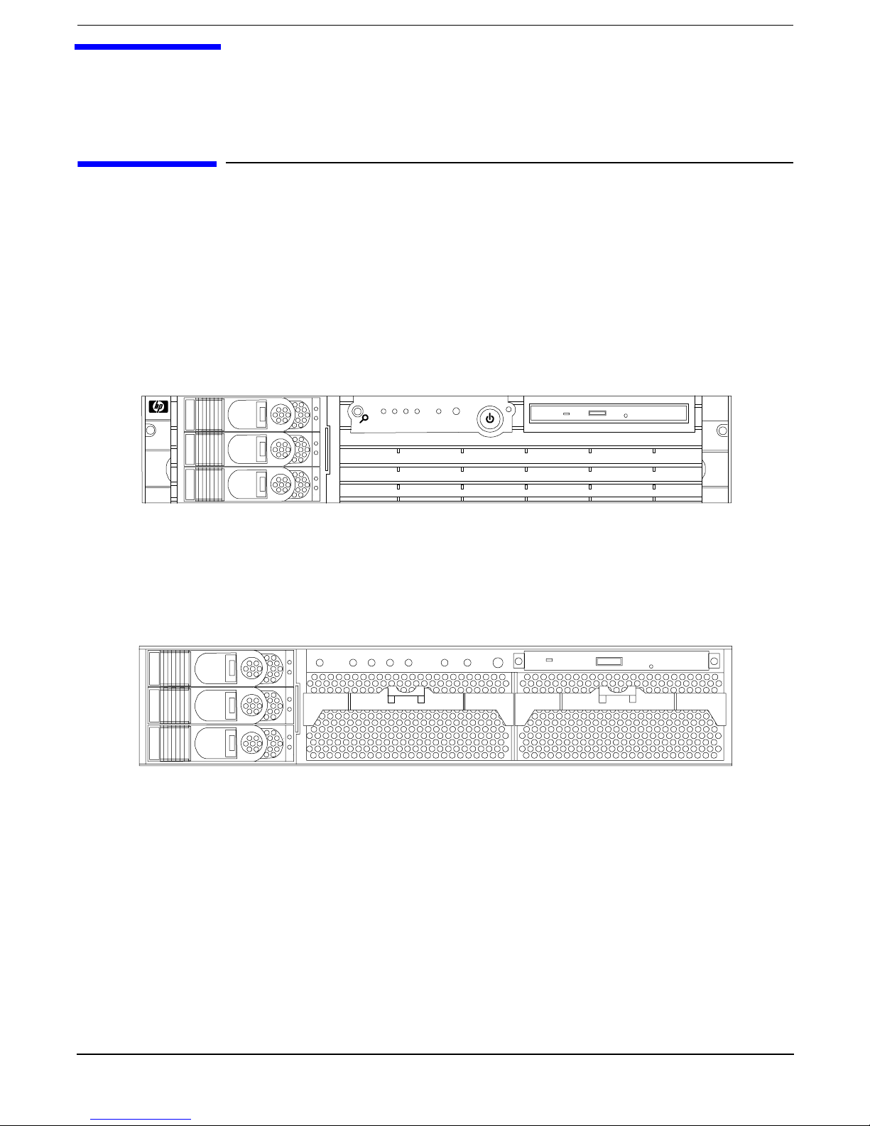
Figure 1-1 HP 9000 rp3410 and HP 9000 rp3440 Server (front view)
Figure 1-2 HP 9000 rp3410 and HP 9000 rp3440 Server (front view with bezel
removed)
Server Overview and Unpacking
Server Overview
Chapter 1
12
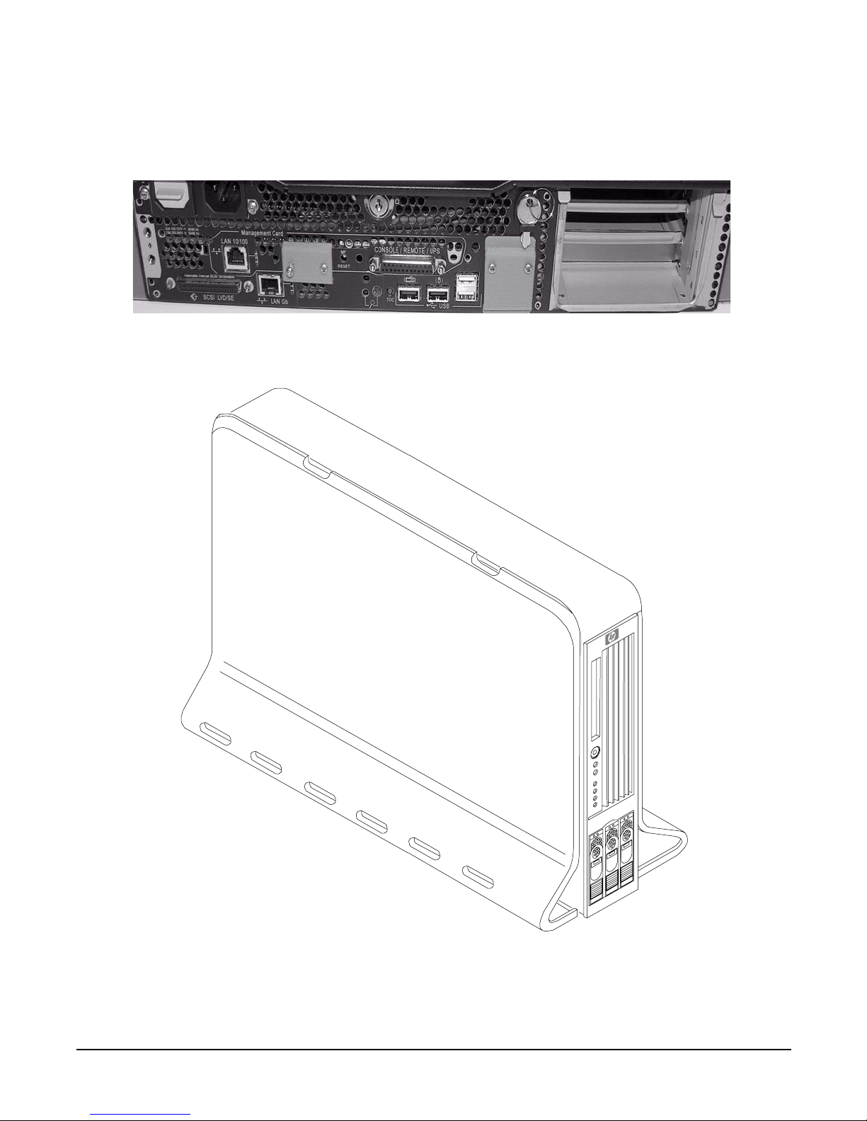
Figure 1-3 HP 9000 rp3410 and HP 9000 rp3440 Server (rear view)
Figure 1-4 HP 9000 rp3410 and HP 9000 rp3440 Server (tower version)

Server Overview and Unpacking
Unpacking the Server
Chapter 1
13
Unpacking the Server
HP shipping containers protect their contents under normal shipping conditions. After the equipment arrives,
carefully inspect each carton for signs of shipping damage. A tilt indicator is installed on each carton shipped.
The beads in the indicator will roll to the upper position if the container has been tilted to an angle that could
cause equipment damage. The tilt indicator itself will have two windows and each window under normal
conditions will show four beads present. If a carton has been mishandled, accidentally dropped, or knocked
against something, the tilt indicator will indicate missing beads. If damage is found, document the damage
with photographs and contact the transport carrier immediately.
If the equipment has any damage, you must obtain a damage claim form from the shipping representative.
You must complete the form and return it to the shipping representative.
Unpacking a Non-Racked Server
NOTE HP recommends the use of a lifter, such as a RonI Company model 17000 SP 400 lifting device,
when moving a non-racked system.
Unloading with a Lifter
To unload the server from the pallet using a lifter, perform the following steps:
WAR NING Use caution when using a lifter. Because of the weight of the HP 9000 rp3410 or HP
9000 rp3440 server, the server must be centered on the lifter forks before raising it
off the pallet to avoid injury.
Step 1. Follow the instructions on the outside of the server packaging to remove the banding and carton top
from the server pallet.
Step 2. Remove all cartons from the pallet, leaving only the server.
Step 3. Lower the cardboard from the side on which the lifter will be inserted and slide the server as close
as possible to the edge of the pallet.
Step 4. Break off any foam packaging which could prevent the lifter from being fully inserted under the
server. Do not remove the foam packaging from the corners of the system. This foam is required to
elevate the system and allow the forks of the lifter to be placed under the server.
Step 5. Insert the lifter forks under the server.
Step 6. Carefully roll the lift forward until it is fully positioned against the side of the server.
Step 7. Slowly raise the server off the pallet until it clears the pallet cushions.
Step 8. Carefully roll the lifter and server away from the pallet. Do not raise the server any higher than
necessary when moving it over to the rack.

Server Overview and Unpacking
Unpacking the Server
Chapter 1
14
Installing the HP Server into a Rack
HP Rack
All HP 9000 rp3410 and HP 9000 rp3440 servers that are to be installed into racks are shipped with
equipment mounting slides. With every set of slides comes an installation guide: Installation Guide,
Mid-Weight Slide Kit, 5065-7291. Follow the steps in this installation guide to determine where and how to
place the server into the rack.
Non-HP Rack
There is a guide for evaluating the installation of HP equipment in non-HP racks. This document should be
utilized when there is a need to evaluate and qualify whether any HP equipment can be installed,
maintained, and serviced in a non-HP rack.
The guide is located on the Web at http://www.hp.com/racksolutions.
Once there, select “mounting information” from the menu on the left side, then select the guide titled
Mounting in Non-HP Racks.
Converting Server to Rack from Tower and to Tower from Rack
If you wish to change your rack-mount HP server to a tower system or your tower system to a rack-mount,
read and follow the instructions in: Rack to Tower and Tower to Rack Conversion Guide, A7136-96002.

Chapter 2
15
2 Installing and Configuring
This chapter provides information on the controls and indicators of the HP server and instructions required
for installing additional components and configuring the HP 9000 rp3410 or HP 9000 rp3440 server.
The following additional components may be added to the HP server:
• Internal hard disk drives
• DVD-ROM drive
• Memory DIMMs
• PCI cards
• Power supply
• Dual processor module
Safety Information
This chapter describes installing additional or optional hardware to your HP 9000 rp3410 and HP 9000
rp3440 servers. Use care to prevent injury and equipment damage when performing these procedures.
Voltages may be present within the server. Many assemblies are sensitive to damage by electrostatic
discharge.
To ensure safe handling of components and to prevent injury to personnel, or damage to the HP server,
adhere to the following procedures:
• If removing or installing a hot-swap or hot-plug item, follow the instructions provided in this guide
• If installing a hot-swap item when power is applied (fans are running), reinstall the server cover
immediately to prevent overheating
• If installing an assembly that is not hot-swappable, disconnect the power cable(s) from the server
external power connector(s)
WARNING Ensure that the system is powered-down and all power sources have been
disconnected from the server prior to removing or replacing a removable media
drive.
Voltages are present at various locations within the server whenever an AC
power source is connected. This voltage is present even when the main power
switch is in the off position.
Failure to observe this warning could result in personal injury or damage to
equipment.
• Do not wear loose clothing that may snag or catch on the server or on other items
• Do not wear clothing subject to static charge build-up, such as wool or synthetic materials
• If installing an internal assembly, wear an antistatic wrist strap and use a grounding mat, such as those
included in the Electrically Conductive Field Service Grounding Kit (P/N 9300-1155)

Chapter 2
Installing and Configuring
Service Tools Required
16
• Handle accessory boards and components by the edges only. Do not touch any metal-edge connectors or
any electrical components on accessory boards.
Service Tools Required
Service of this product may require one or more of the following tools:
• Electrically Conductive Field Service Kit (P/N 9300-1155)
• 1/4 inch flat blade screwdriver
•ACX-15 Torx® screwdriver
• Special processor tool kit, (P/N 5069-5441)
Chapter 2
Installing and Configuring
Control Panel
17
Control Panel
The control panel of the HP 9000 rp3410 or HP 9000 rp3440 server provides the controls and indicators
commonly used for operation.
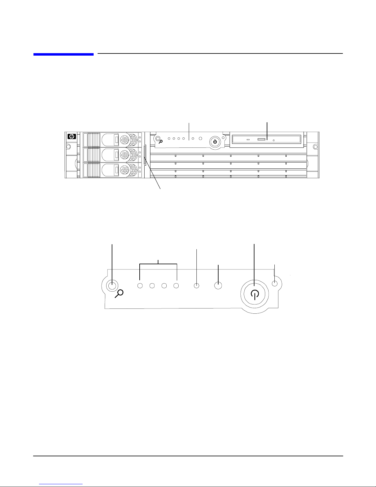
Figure 2-1 Front View
Figure 2-2 Control Panel
Control Panel
DVD Drive
System Product
Label (pull-out)
HDD 3
HDD 2
HDD 1
1 2 3 4 LAN System
System
LED
Power
On/Off LED
Power Button
Diagnostics LEDs
(Disabled)
Locator Button and LED
LAN
LED
Chapter 2
Installing and Configuring
Control Panel
18
Table 2-1 Control Panel LEDs and Switches
Name Function
Power on/off
LED
The green power on/off LED is illuminated when the power is on
Power button Controls the power supply (turns system power on or off) if power is available to the
power supply. (Controls both power supplies if two are installed)
If power is off but power is available to the power supplies, pressing the Power button:
Momentarily (less than 1 second) turns on the power supplies and applies power to
server circuits
For more than 1 second and then released, has no effect
If power is on and the system is at initial system loader (ISL), pressing the Power button:
Momentarily (less than 1 second) has no effect
For more than 1 second, but less than 5 seconds—do not use. This selection initiates
e-buzzer functions that are not supported in the HP 9000 rp3410 and HP 9000 rp3440
servers
For more than 5 seconds (and then released) causes an immediate and hard power down
If power is on and the system is at the boot console handler (BCH), pressing the Power
button:
Momentarily (less than 1 second) causes an immediate and hard power down
For more than 1 second, but less than 5 seconds—do not use. This selection initiates
e-buzzer functions that are not supported in the HP 9000 rp3410 and HP 9000 rp3440
servers
For more than 5 seconds (and then released) causes an immediate and hard power down
If power is on but the OS has been shut down, pressing the Power button:
Momentarily (less than 1 second) has no effect
For more than 1 second, but less than 5 seconds—do not use. This selection initiates
e-buzzer functions that are not supported in the HP 9000 rp3410 and HP 9000 rp3440
servers
For more than 5 seconds (and then released) causes an immediate and hard power down
If the OS is running, pressing the Power button:
Momentarily (less than 1 second) has no effect
For more than 1 second, but less than 5 seconds—do not use. This selection initiates
e-buzzer functions that are not supported in the HP 9000 rp3410 and HP 9000 rp3440
servers
For more than 5 seconds (and then released) causes an immediate and hard power down
System LED The System LED provides information about the system status. When operation is
normal, the LED is green. When there is a system warning, the LED is flashing yellow.
When there is a system fault, the LED is flashing red
a

Chapter 2
Installing and Configuring
Control Panel
19
LAN LED The LAN LED provides status information about the LAN interface. When the LAN LED
is flashing, there is activity on the LAN
Locator button
and LED
The locator button and LED are used to help locate this server within a rack of servers.
When the button is engaged, the blue LED illuminates and an additional blue LED on
the rear panel of the server illuminates. This function may be remotely activated.
a. See the Troubleshooting chapter of this guide and refer to the HP 9000 rp3410 and HP 9000
rp3440 Operations Guide for details and information provided by the system LEDs.
Table 2-1 Control Panel LEDs and Switches (Continued)
Name Function
Chapter 2
Installing and Configuring
Additional Controls and Indicators
20
Additional Controls and Indicators
The HP 9000 rp3410 or HP 9000 rp3440 server can have up to three low-voltage differential (LVD), 3.5 inch
form factor hard disk drives (HDDs) installed. These hard disk drives have LEDs that provide status and
activity information.
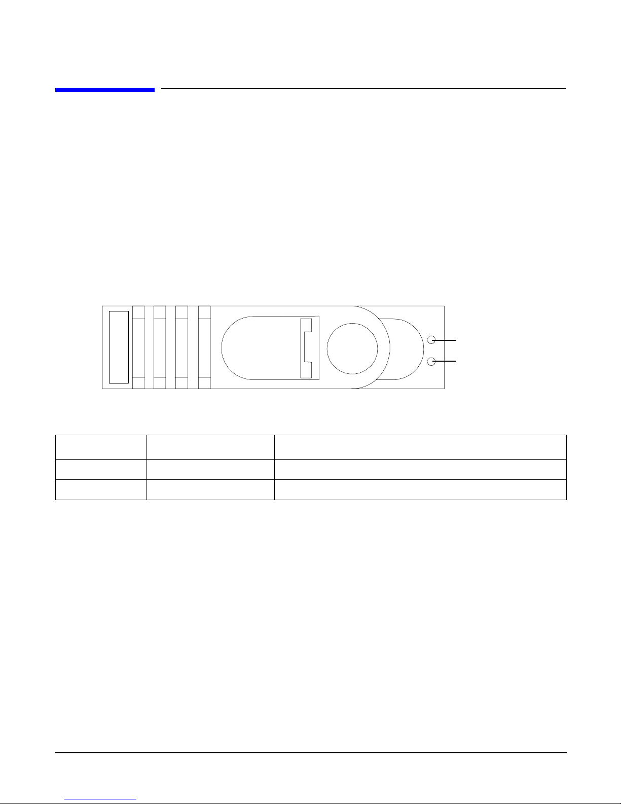
Hard Disk Drive Indicators
The hard disk drives have two LEDs per drive, as described below.
• Status LED—The drive status LED is not used on the HP 9000 rp3410 or HP 9000 rp3440 server.
• Activity LED—The Drive Activity LED is flashing green and indicates disk drive activity. This LED is
directly controlled by the disk drive and turns on when a drive is accessed.
Figure 2-3 Hard Disk Drive LED Indicators
Table 2-2 Hard Disk Drive LED Definitions
LED Activity Description
Status LED None Not used
Activity LED Flashing green Ready/scanning hard drive
Status LED
- (Not used)
Activity LED
Chapter 2
Installing and Configuring
Additional Controls and Indicators
21
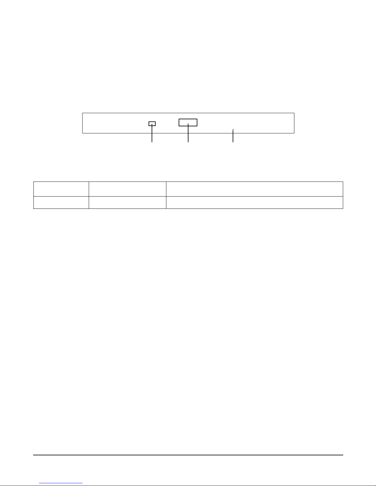
Optional Removable Media Drive
The HP 9000 rp3410 or HP 9000 rp3440 server is delivered without a removable media drive. Either a
DVD-ROM or CD-RW/DVD-ROM drive may be added. Each of these optional devices has one activity LED.
Figure 2-4 DVD–ROM or CD-RW/DVD-ROM LED Indicators
Table 2-3 DVD Drive LED Definitions
LED Activity Description
Activity LED Flashing green Drive is active
DVD
Activity
LED
Eject
Button
Emergency
Eject
Chapter 2
Installing and Configuring
Rear Panel
22
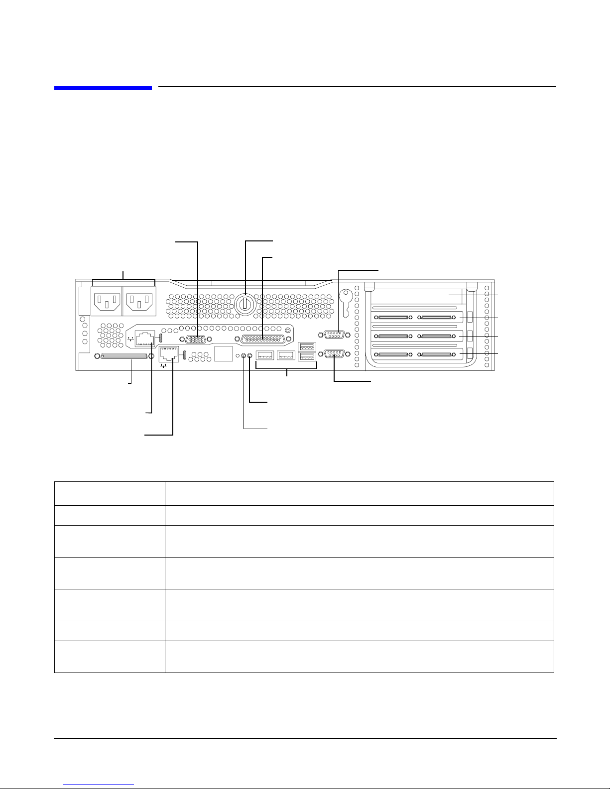
Rear Panel
The HP 9000 rp3410 or HP 9000 rp3440 server rear panel includes communication ports, I/O ports, AC power
connector, locator LED, and button. Additional LEDs located on the rear panel of the HP 9000 rp3410 or
HP 9000 rp3440 server signal the operational status of:
• 10/100/1000 base-T ethernet LAN port
• iLO manageability card LAN port
Figure 2-5 Rear View
Table 2-4 Rear Panel Connectors and Switches
Connector/Switch Function
AC power Primary power connection for the server
LVD/SE SCSI 68-pin, low-voltage differential, single-ended U160 SCSI. This connector provides
external SCSI connection on SCSI Channel B
(1 GB) 10/100/1000
LAN
10/100/1000 base-T ethernet LAN connector
Serial A (console) &
Serial B (do not use)
9-pin male serial ports—factory use only
USB Four universal serial bus (USB 2.0) connectors
TOC Transfer of control button. Halts all system processing and I/O activity and
restarts the computer system
AC Power Receptacle
LVD/SE SCSI
iLO Manageability
Card LAN port
10/100/1000 LAN
port
VGA Port-disabled
DO NOT USE
USB Ports
System Lock
Console/Serial Port A (factory use onl
y
Locator Button and LED
TOC Button
Console Serial Port B
(factory use only)
Console/Remote/UPS
PCI Slot 1
PCI Slot 2
PCI Slot 3
PCI Slot 4
Chapter 2
Installing and Configuring
Rear Panel
23
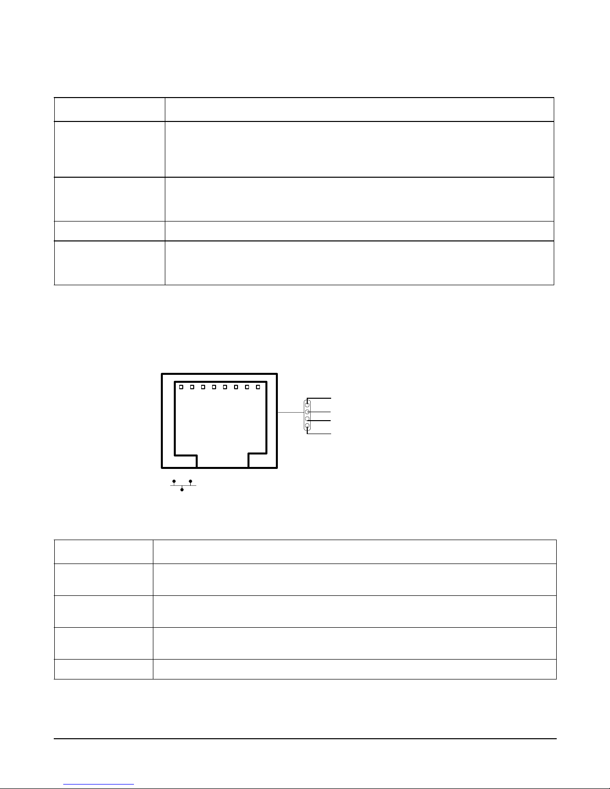
10/100/1000 Base-T Ethernet LAN Connector
The rear panel 10/100/1000 base-T ethernet LAN connector has the following status and activity LEDs.
Figure 2-6 10/100/1000 Base-T Ethernet LAN Connector LEDs
Locator button and
LED
The locator button and LED are used to help locate a server within a rack of
servers. When the button is engaged, the blue LED illuminates and an additional
blue LED on the front panel of the server illuminates. This function may be
remotely activated
Video (not used) 15-pin female video connector. DISABLED—DO NOT USE. To enable video
capability you must obtain the supported A6150 video PCI card. Refer to the
associated ReadMe, A6150-90001
Console/remote/UPS 25-pin female serial data bus connector for the iLO manageability card
10/100 iLO
manageability card
LAN
10 MB/100 MB LAN connector for the iLO manageability card
Table 2-5 10/100/1000 Base-T Ethernet LAN Connector LEDs
LED Description
1000BT Blinking green, the 1000 MHz with ethernet protocol and twisted-pair wiring is
enabled; off—no link
100BT Blinking green, the 100 MHz with ethernet protocol and twisted-pair wiring is
enabled; off—no link
10BT Blinking green, the 10 MHz with ethernet protocol and twisted-pair wiring is
enabled; off—no link
Activity Blinking green, LAN activity
Table 2-4 Rear Panel Connectors and Switches (Continued)
Connector/Switch Function
1000BT
100BT
10BT
Activity
Chapter 2
Installing and Configuring
Rear Panel
24
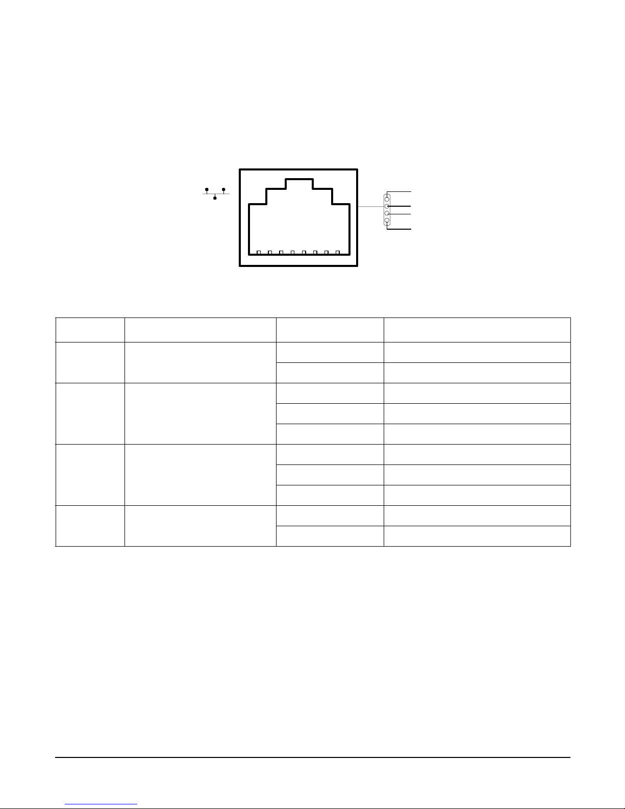
iLO Manageability Card LAN LEDs
The iLO manageability card LAN uses an RJ-45 type connector. This connector has four LEDs that signal
status and activity.
Figure 2-7 iLO Manageability Card LAN LEDs
Table 2-6 iLO Manageability Card LAN LEDs
LAN LED Location Color State
Self-test Top Yellow MP running self-test or error
Off MP has booted
10BT 2nd from top Green 10BT link established
Blinking green 10BT activity
Off No link or 100BT link
100BT 2nd from bottom Green 100BT link established
Blinking green 100BT activity
Off No link or 10BT link
Standby
Power
Bottom Green Standby power on
Off Standby power off
Self-test
10BT
100BT
Standby
Power

Chapter 2
Installing and Configuring
Removing and Replacing System Covers and Bezels
25
Removing and Replacing System Covers and Bezels
To upgrade, remove, or replace most system components, you must first remove the covers from the system
chassis. This section explains how to remove and replace the covers for both rack and tower-mounted
configurations.
WAR NING Do not remove the system cover without first turning the system off and unplugging
the power cord from the outlet or power protection device unless you are only
replacing a hot-swappable fan. Always replace the cover before turning the system
on.
Rack-Mount System
To access the internal components on a rack-mounted system, pull the system out onto the rail guides and
remove the metal cover.
Accessing a Rack Mounted Server
The HP 9000 rp3410 and HP 9000 rp3440 servers are designed to be rack mounted. The following procedure
explains how to gain access to a server that is mounted in an approved rack. For slide installation
instructions, refer to the Installation Guide, Mid-Weight Slide Kit, 5065-7291. This document can be accessed
at: http://www.hp.com/racksolutions.
WAR NING Ensure that all anti-tip features (front and rear anti-tip feet installed; adequate
ballast properly placed; and so on) are employed prior to extending the server.
Extend the Server from the Rack
NOTE Ensure that there is enough area (approximately 1.5 meters {4.5 ft.}) to fully extend the server
out the front to work on it.
To extend the server from the rack, perform the following steps:
NOTE If you are replacing a hot-swappable item, you can leave the system on and external cables
(including the power cord) connected.
Step 1. Turn off the system and disconnect the power and external cables from the back of the system.
Chapter 2
Installing and Configuring
Removing and Replacing System Covers and Bezels
26
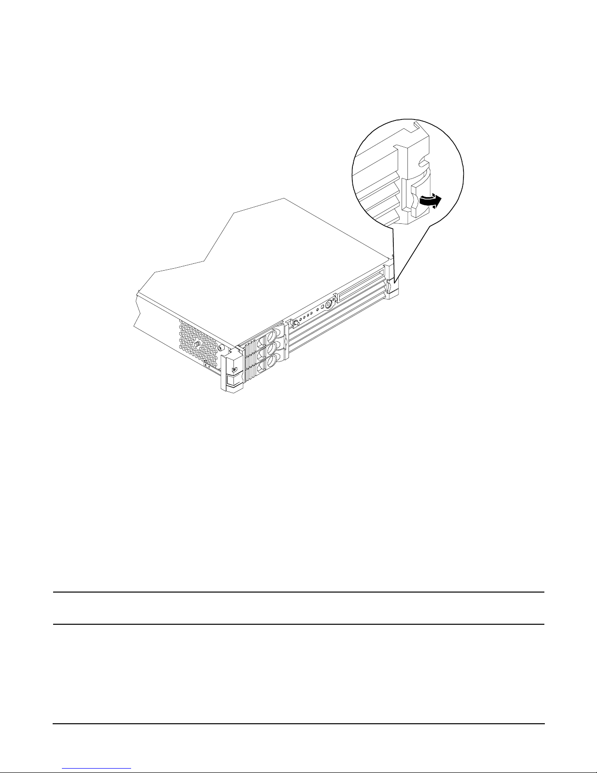
Step 2. Release the rack latches by rotating them outward (Figure 2-8).
Figure 2-8 Release the Rack Latches
Step 3. Slide the system out of the rack until the guide-rail release clips are visible.
Insert the Server into the Rack
To insert the server into the rack, perform the following steps:
Step 1. Press the rail clips on either side of the server inward and push the server into the rack until it
stops.
Step 2. Verify that the rack latches are closed.
Removing and Replacing the Metal Cover
Removal of this cover is necessary when installing or removing many components.
Removing the Metal Cover
NOTE If you are replacing a hot-swappable item, you can leave the system on and external cables
(including the power cord) connected.
Step 1. Turn off the system and disconnect the power and external cables from the back of the system.
Chapter 2
Installing and Configuring
Removing and Replacing System Covers and Bezels
27
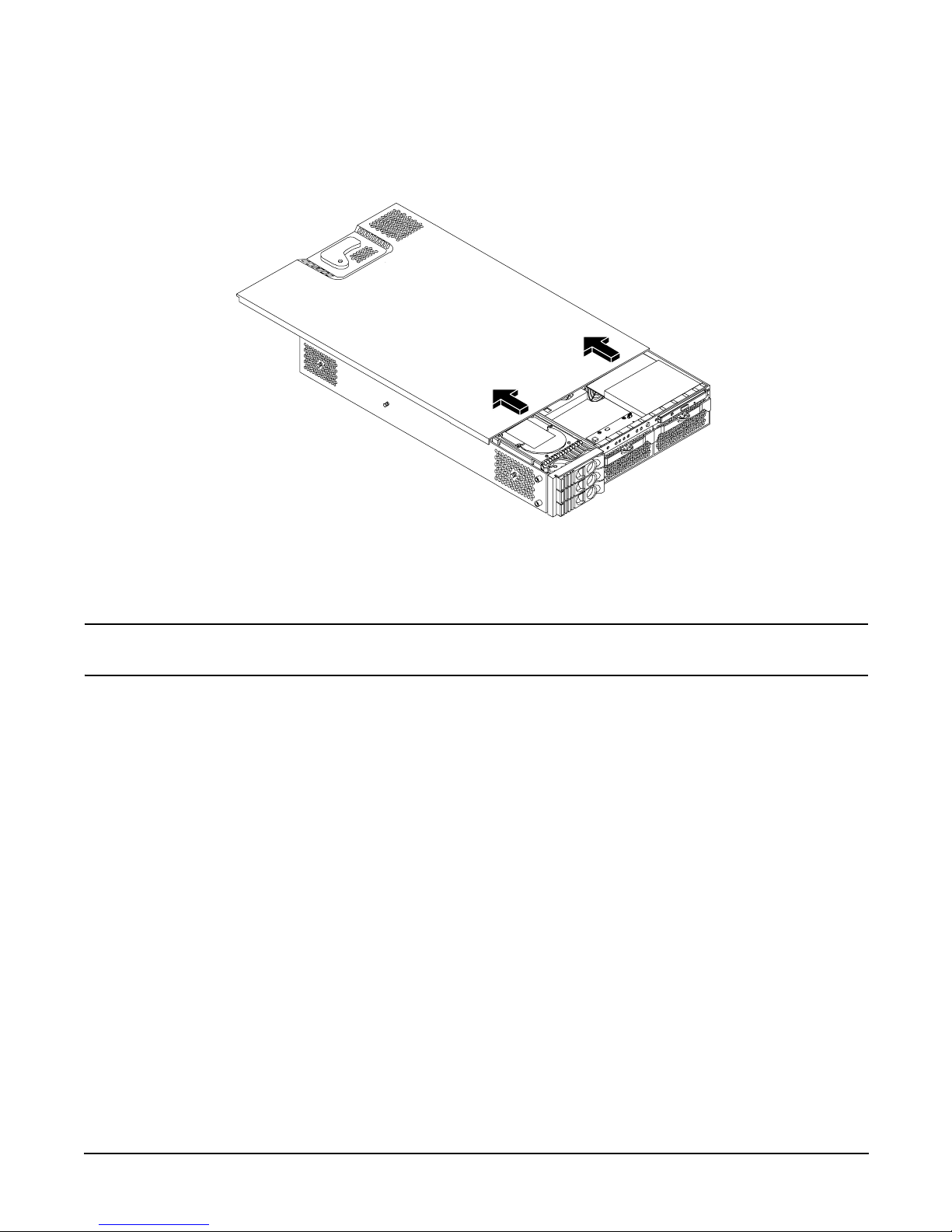
Step 2. Ensure the top cover lock keyswitch is in the unlocked position. Rotate the blue release lever
toward the back of the system and slide the cover toward the back of the system (Figure 2-9).
Figure 2-9 Removing and Replacing the Metal Cover
Step 3. Lift the cover off the system chassis.
Replacing the Metal Cover
CAUTION Secure any wires or cables in your system so they will not get cut or interfere with the
replacement of the cover.
Chapter 2
Installing and Configuring
Removing and Replacing System Covers and Bezels
28
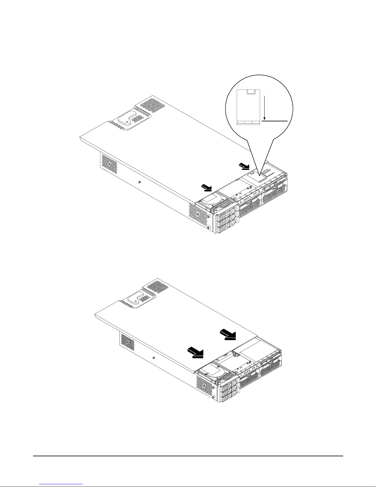
Step 1. Align the front edge of the cover with the alignment mark on the optical drive bay (Figure 2-10).
Figure 2-10 Aligning the Metal Cover
Step 2. Grasp the blue release lever and slide the cover toward the front of the system until the lever snaps
into place (Figure 2-11).
Figure 2-11 Closing the Metal Cover
Step 3. Slide the system into the rack enclosure and reconnect the power and external cables.
To replace cover,
align front edge here
then slide forward
 Loading...