

Page 1

User Service Guide
HP 9000 rp3410 and HP 9000 rp3440
Manufacturing Part Number: A7137-96008-ed5
Fifth Edition
September 2008
© Copyright 2003-2008 Hewlett-Packard Development Company, L.P.
Page 2

Legal Notices
Copyright Notices. © Copyright 2003-2008 Hewlett-Packard Development Company, L.P.
The information contained herein is subject to change without notice. The only warranties for HP products
and services are set forth in the express warranty statements accompanying such products and services.
Nothing herein should be construed as constituting an additional warranty. HP shall not be liable for
technical or editorial errors or omissions contained herein.
Printed in U.S.A.
Intel, Pentium, Intel Inside, Itanium, and the Intel Inside logo are trademarks or registered trademarks of
Intel Corporation or its subsidiaries in the United States and other countries.
Linux is a U.S. registered trademark of Linus Torvalds.
2
Page 3

1. Overview
HP 9000 rp3410 and rp3440 Server Views. . . . . . . . . . . . . . . . . . . . . . . . . . . . . . . . . . . . . . . . . . . . . . . . 20
Detailed Server Description . . . . . . . . . . . . . . . . . . . . . . . . . . . . . . . . . . . . . . . . . . . . . . . . . . . . . . . . . . . 22
Processor . . . . . . . . . . . . . . . . . . . . . . . . . . . . . . . . . . . . . . . . . . . . . . . . . . . . . . . . . . . . . . . . . . . . . . . . . 22
Memory . . . . . . . . . . . . . . . . . . . . . . . . . . . . . . . . . . . . . . . . . . . . . . . . . . . . . . . . . . . . . . . . . . . . . . . . . . 22
PCI Riser . . . . . . . . . . . . . . . . . . . . . . . . . . . . . . . . . . . . . . . . . . . . . . . . . . . . . . . . . . . . . . . . . . . . . . . . . 23
Internal Core I/O. . . . . . . . . . . . . . . . . . . . . . . . . . . . . . . . . . . . . . . . . . . . . . . . . . . . . . . . . . . . . . . . . . . 23
External Core I/O . . . . . . . . . . . . . . . . . . . . . . . . . . . . . . . . . . . . . . . . . . . . . . . . . . . . . . . . . . . . . . . . . . 23
Power Supply Unit . . . . . . . . . . . . . . . . . . . . . . . . . . . . . . . . . . . . . . . . . . . . . . . . . . . . . . . . . . . . . . . . . 23
System Board Manageability . . . . . . . . . . . . . . . . . . . . . . . . . . . . . . . . . . . . . . . . . . . . . . . . . . . . . . . . . 23
Enhanced Server Manageability Using the Integrity iLO MP . . . . . . . . . . . . . . . . . . . . . . . . . . . . . . 24
Hard Disk Drives . . . . . . . . . . . . . . . . . . . . . . . . . . . . . . . . . . . . . . . . . . . . . . . . . . . . . . . . . . . . . . . . . . 24
Internal RAID . . . . . . . . . . . . . . . . . . . . . . . . . . . . . . . . . . . . . . . . . . . . . . . . . . . . . . . . . . . . . . . . . . . . . 24
Firmware. . . . . . . . . . . . . . . . . . . . . . . . . . . . . . . . . . . . . . . . . . . . . . . . . . . . . . . . . . . . . . . . . . . . . . . . . 24
Dimensions and Values . . . . . . . . . . . . . . . . . . . . . . . . . . . . . . . . . . . . . . . . . . . . . . . . . . . . . . . . . . . . . 25
System Board . . . . . . . . . . . . . . . . . . . . . . . . . . . . . . . . . . . . . . . . . . . . . . . . . . . . . . . . . . . . . . . . . . . . . 25
Controls, Ports, and LEDs . . . . . . . . . . . . . . . . . . . . . . . . . . . . . . . . . . . . . . . . . . . . . . . . . . . . . . . . . . . . . 35
Control Panel . . . . . . . . . . . . . . . . . . . . . . . . . . . . . . . . . . . . . . . . . . . . . . . . . . . . . . . . . . . . . . . . . . . . . 35
Additional Controls and Indicators . . . . . . . . . . . . . . . . . . . . . . . . . . . . . . . . . . . . . . . . . . . . . . . . . . . . 37
Rear Panel. . . . . . . . . . . . . . . . . . . . . . . . . . . . . . . . . . . . . . . . . . . . . . . . . . . . . . . . . . . . . . . . . . . . . . . . 38
Powering the Server On and Off . . . . . . . . . . . . . . . . . . . . . . . . . . . . . . . . . . . . . . . . . . . . . . . . . . . . . . . . 44
Power States . . . . . . . . . . . . . . . . . . . . . . . . . . . . . . . . . . . . . . . . . . . . . . . . . . . . . . . . . . . . . . . . . . . . . . 44
Powering On the Server . . . . . . . . . . . . . . . . . . . . . . . . . . . . . . . . . . . . . . . . . . . . . . . . . . . . . . . . . . . . . 45
Powering Off the Server . . . . . . . . . . . . . . . . . . . . . . . . . . . . . . . . . . . . . . . . . . . . . . . . . . . . . . . . . . . . . 45
Contents
2. System Specifications
System Configuration . . . . . . . . . . . . . . . . . . . . . . . . . . . . . . . . . . . . . . . . . . . . . . . . . . . . . . . . . . . . . . . . 47
Dimensions and Values . . . . . . . . . . . . . . . . . . . . . . . . . . . . . . . . . . . . . . . . . . . . . . . . . . . . . . . . . . . . . . . 48
Grounding. . . . . . . . . . . . . . . . . . . . . . . . . . . . . . . . . . . . . . . . . . . . . . . . . . . . . . . . . . . . . . . . . . . . . . . . . . 49
Electrical Specifications. . . . . . . . . . . . . . . . . . . . . . . . . . . . . . . . . . . . . . . . . . . . . . . . . . . . . . . . . . . . . . . 49
AC Power Cords . . . . . . . . . . . . . . . . . . . . . . . . . . . . . . . . . . . . . . . . . . . . . . . . . . . . . . . . . . . . . . . . . . . 49
Circuit Breaker . . . . . . . . . . . . . . . . . . . . . . . . . . . . . . . . . . . . . . . . . . . . . . . . . . . . . . . . . . . . . . . . . . . . 50
System Power Specifications . . . . . . . . . . . . . . . . . . . . . . . . . . . . . . . . . . . . . . . . . . . . . . . . . . . . . . . . . 50
Power and Cooling . . . . . . . . . . . . . . . . . . . . . . . . . . . . . . . . . . . . . . . . . . . . . . . . . . . . . . . . . . . . . . . . . 51
Environmental Specifications . . . . . . . . . . . . . . . . . . . . . . . . . . . . . . . . . . . . . . . . . . . . . . . . . . . . . . . . . . 51
Operating Environment . . . . . . . . . . . . . . . . . . . . . . . . . . . . . . . . . . . . . . . . . . . . . . . . . . . . . . . . . . . . . 52
Environmental Temperature Sensor . . . . . . . . . . . . . . . . . . . . . . . . . . . . . . . . . . . . . . . . . . . . . . . . . . . 52
Nonoperating Environment . . . . . . . . . . . . . . . . . . . . . . . . . . . . . . . . . . . . . . . . . . . . . . . . . . . . . . . . . . 52
Cooling. . . . . . . . . . . . . . . . . . . . . . . . . . . . . . . . . . . . . . . . . . . . . . . . . . . . . . . . . . . . . . . . . . . . . . . . . . . 52
Acoustic Noise Specification. . . . . . . . . . . . . . . . . . . . . . . . . . . . . . . . . . . . . . . . . . . . . . . . . . . . . . . . . . 53
Physical and Environmental Specifications . . . . . . . . . . . . . . . . . . . . . . . . . . . . . . . . . . . . . . . . . . . . . . . 54
3. Installing the System
Introduction . . . . . . . . . . . . . . . . . . . . . . . . . . . . . . . . . . . . . . . . . . . . . . . . . . . . . . . . . . . . . . . . . . . . . . . . 55
Server Views . . . . . . . . . . . . . . . . . . . . . . . . . . . . . . . . . . . . . . . . . . . . . . . . . . . . . . . . . . . . . . . . . . . . . . 56
Detailed Server Description . . . . . . . . . . . . . . . . . . . . . . . . . . . . . . . . . . . . . . . . . . . . . . . . . . . . . . . . . . 58
3
Page 4

Contents
Safety Information . . . . . . . . . . . . . . . . . . . . . . . . . . . . . . . . . . . . . . . . . . . . . . . . . . . . . . . . . . . . . . . . . 59
Installation Sequence and Checklist . . . . . . . . . . . . . . . . . . . . . . . . . . . . . . . . . . . . . . . . . . . . . . . . . . . 60
Unpacking and Inspecting the Server . . . . . . . . . . . . . . . . . . . . . . . . . . . . . . . . . . . . . . . . . . . . . . . . . . . 61
Verifying Site Preparation . . . . . . . . . . . . . . . . . . . . . . . . . . . . . . . . . . . . . . . . . . . . . . . . . . . . . . . . . . . 61
Inspecting the Shipping Containers for Damage . . . . . . . . . . . . . . . . . . . . . . . . . . . . . . . . . . . . . . . . . 61
Unpacking the Server . . . . . . . . . . . . . . . . . . . . . . . . . . . . . . . . . . . . . . . . . . . . . . . . . . . . . . . . . . . . . . . 61
Checking the Inventory . . . . . . . . . . . . . . . . . . . . . . . . . . . . . . . . . . . . . . . . . . . . . . . . . . . . . . . . . . . . . 61
Returning Damaged Equipment . . . . . . . . . . . . . . . . . . . . . . . . . . . . . . . . . . . . . . . . . . . . . . . . . . . . . . 62
Unloading the Server with a Lifter . . . . . . . . . . . . . . . . . . . . . . . . . . . . . . . . . . . . . . . . . . . . . . . . . . . . 62
Installing Additional Components . . . . . . . . . . . . . . . . . . . . . . . . . . . . . . . . . . . . . . . . . . . . . . . . . . . . . . 63
Removing and Replacing Server Covers and Bezels. . . . . . . . . . . . . . . . . . . . . . . . . . . . . . . . . . . . . . . 63
Installing Internal Hard Disk Drives . . . . . . . . . . . . . . . . . . . . . . . . . . . . . . . . . . . . . . . . . . . . . . . . . . 73
Installing a DVD Drive. . . . . . . . . . . . . . . . . . . . . . . . . . . . . . . . . . . . . . . . . . . . . . . . . . . . . . . . . . . . . . 77
Removing and Replacing Airflow Guides . . . . . . . . . . . . . . . . . . . . . . . . . . . . . . . . . . . . . . . . . . . . . . . 78
Installing Additional System Memory. . . . . . . . . . . . . . . . . . . . . . . . . . . . . . . . . . . . . . . . . . . . . . . . . . 84
Removing and Replacing the PCI Card Cage . . . . . . . . . . . . . . . . . . . . . . . . . . . . . . . . . . . . . . . . . . . . 88
Installing PCI Cards. . . . . . . . . . . . . . . . . . . . . . . . . . . . . . . . . . . . . . . . . . . . . . . . . . . . . . . . . . . . . . . . 90
Installing an Additional Power Supply . . . . . . . . . . . . . . . . . . . . . . . . . . . . . . . . . . . . . . . . . . . . . . . . . 92
Installing an Additional Processor Module . . . . . . . . . . . . . . . . . . . . . . . . . . . . . . . . . . . . . . . . . . . . . . 93
Replacing the System Battery . . . . . . . . . . . . . . . . . . . . . . . . . . . . . . . . . . . . . . . . . . . . . . . . . . . . . . . 102
Installing the Server Into a Rack, Non-HP Rack, or Pedestal . . . . . . . . . . . . . . . . . . . . . . . . . . . . . . . 104
HP Rack. . . . . . . . . . . . . . . . . . . . . . . . . . . . . . . . . . . . . . . . . . . . . . . . . . . . . . . . . . . . . . . . . . . . . . . . . 104
Non-HP Rack. . . . . . . . . . . . . . . . . . . . . . . . . . . . . . . . . . . . . . . . . . . . . . . . . . . . . . . . . . . . . . . . . . . . . 104
Pedestal Mount . . . . . . . . . . . . . . . . . . . . . . . . . . . . . . . . . . . . . . . . . . . . . . . . . . . . . . . . . . . . . . . . . . . 104
Connecting the Cables . . . . . . . . . . . . . . . . . . . . . . . . . . . . . . . . . . . . . . . . . . . . . . . . . . . . . . . . . . . . . . . 105
AC Input Power. . . . . . . . . . . . . . . . . . . . . . . . . . . . . . . . . . . . . . . . . . . . . . . . . . . . . . . . . . . . . . . . . . . 105
Core I/O Connections . . . . . . . . . . . . . . . . . . . . . . . . . . . . . . . . . . . . . . . . . . . . . . . . . . . . . . . . . . . . . . 105
Applying Standby Power to the Server . . . . . . . . . . . . . . . . . . . . . . . . . . . . . . . . . . . . . . . . . . . . . . . . 106
Connecting to the LAN . . . . . . . . . . . . . . . . . . . . . . . . . . . . . . . . . . . . . . . . . . . . . . . . . . . . . . . . . . . . . 106
Console Setup . . . . . . . . . . . . . . . . . . . . . . . . . . . . . . . . . . . . . . . . . . . . . . . . . . . . . . . . . . . . . . . . . . . . . . 107
Setup Checklist . . . . . . . . . . . . . . . . . . . . . . . . . . . . . . . . . . . . . . . . . . . . . . . . . . . . . . . . . . . . . . . . . . . 107
Setup Flowchart . . . . . . . . . . . . . . . . . . . . . . . . . . . . . . . . . . . . . . . . . . . . . . . . . . . . . . . . . . . . . . . . . . 108
Preparation . . . . . . . . . . . . . . . . . . . . . . . . . . . . . . . . . . . . . . . . . . . . . . . . . . . . . . . . . . . . . . . . . . . . . . 109
Configuring the iLO MP LAN Using DHCP and DNS . . . . . . . . . . . . . . . . . . . . . . . . . . . . . . . . . . . . 110
Configuring the iLO MP LAN Using ARP Ping . . . . . . . . . . . . . . . . . . . . . . . . . . . . . . . . . . . . . . . . . 110
Configuring the iLO MP LAN Using the RS-232 Serial Port. . . . . . . . . . . . . . . . . . . . . . . . . . . . . . . 112
Logging In to the iLO MP. . . . . . . . . . . . . . . . . . . . . . . . . . . . . . . . . . . . . . . . . . . . . . . . . . . . . . . . . . . 114
Additional Setup . . . . . . . . . . . . . . . . . . . . . . . . . . . . . . . . . . . . . . . . . . . . . . . . . . . . . . . . . . . . . . . . . . 114
Accessing the Host Console . . . . . . . . . . . . . . . . . . . . . . . . . . . . . . . . . . . . . . . . . . . . . . . . . . . . . . . . . . . 116
Accessing the Host Console With the TUI - CO Command . . . . . . . . . . . . . . . . . . . . . . . . . . . . . . . . 116
Interacting with the iLO MP Using the Web GUI . . . . . . . . . . . . . . . . . . . . . . . . . . . . . . . . . . . . . . . 116
Accessing the Graphic Console Using VGA. . . . . . . . . . . . . . . . . . . . . . . . . . . . . . . . . . . . . . . . . . . . . 117
Powering the Server ON and OFF . . . . . . . . . . . . . . . . . . . . . . . . . . . . . . . . . . . . . . . . . . . . . . . . . . . . . 119
Power States . . . . . . . . . . . . . . . . . . . . . . . . . . . . . . . . . . . . . . . . . . . . . . . . . . . . . . . . . . . . . . . . . . . . . 119
Powering On the Server . . . . . . . . . . . . . . . . . . . . . . . . . . . . . . . . . . . . . . . . . . . . . . . . . . . . . . . . . . . . 119
Powering Off the Server . . . . . . . . . . . . . . . . . . . . . . . . . . . . . . . . . . . . . . . . . . . . . . . . . . . . . . . . . . . . 120
4
Page 5

Contents
Booting the Operating System . . . . . . . . . . . . . . . . . . . . . . . . . . . . . . . . . . . . . . . . . . . . . . . . . . . . . . . . 121
Supported Operating System . . . . . . . . . . . . . . . . . . . . . . . . . . . . . . . . . . . . . . . . . . . . . . . . . . . . . . . . 121
Booting and Shutting Down HP-UX . . . . . . . . . . . . . . . . . . . . . . . . . . . . . . . . . . . . . . . . . . . . . . . . . . 121
Verifying the Server Configuration Using Boot Console Handler . . . . . . . . . . . . . . . . . . . . . . . . . . . 123
Troubleshooting . . . . . . . . . . . . . . . . . . . . . . . . . . . . . . . . . . . . . . . . . . . . . . . . . . . . . . . . . . . . . . . . . . . . 124
Troubleshooting Methodology . . . . . . . . . . . . . . . . . . . . . . . . . . . . . . . . . . . . . . . . . . . . . . . . . . . . . . . 124
Troubleshooting Using the Server Power Button . . . . . . . . . . . . . . . . . . . . . . . . . . . . . . . . . . . . . . . . 124
Server Does Not Power On . . . . . . . . . . . . . . . . . . . . . . . . . . . . . . . . . . . . . . . . . . . . . . . . . . . . . . . . . . 125
Operating System Does Not Boot . . . . . . . . . . . . . . . . . . . . . . . . . . . . . . . . . . . . . . . . . . . . . . . . . . . . 125
Operating System Boots with Problems . . . . . . . . . . . . . . . . . . . . . . . . . . . . . . . . . . . . . . . . . . . . . . . 126
Intermittent Server Problems . . . . . . . . . . . . . . . . . . . . . . . . . . . . . . . . . . . . . . . . . . . . . . . . . . . . . . . 126
DVD Problems. . . . . . . . . . . . . . . . . . . . . . . . . . . . . . . . . . . . . . . . . . . . . . . . . . . . . . . . . . . . . . . . . . . . 126
Hard Drive Problems . . . . . . . . . . . . . . . . . . . . . . . . . . . . . . . . . . . . . . . . . . . . . . . . . . . . . . . . . . . . . . 126
Console Problems . . . . . . . . . . . . . . . . . . . . . . . . . . . . . . . . . . . . . . . . . . . . . . . . . . . . . . . . . . . . . . . . . 126
Downloading and Installing the Latest Version of the Firmware . . . . . . . . . . . . . . . . . . . . . . . . . . . 127
Troubleshooting Using LED Indicators. . . . . . . . . . . . . . . . . . . . . . . . . . . . . . . . . . . . . . . . . . . . . . . . 127
Information to Collect Before You Contact Support . . . . . . . . . . . . . . . . . . . . . . . . . . . . . . . . . . . . . . 130
4. Booting the Operating System
Supported Operating System . . . . . . . . . . . . . . . . . . . . . . . . . . . . . . . . . . . . . . . . . . . . . . . . . . . . . . . . . 131
Booting and Shutting Down HP-UX . . . . . . . . . . . . . . . . . . . . . . . . . . . . . . . . . . . . . . . . . . . . . . . . . . . . 132
Standard HP-UX Booting Using Boot Console Handler. . . . . . . . . . . . . . . . . . . . . . . . . . . . . . . . . . . 132
Booting HP-UX in Single-User Mode . . . . . . . . . . . . . . . . . . . . . . . . . . . . . . . . . . . . . . . . . . . . . . . . . 133
Booting HP-UX in LVM Maintenance Mode . . . . . . . . . . . . . . . . . . . . . . . . . . . . . . . . . . . . . . . . . . . . 133
Shutting Down HP-UX . . . . . . . . . . . . . . . . . . . . . . . . . . . . . . . . . . . . . . . . . . . . . . . . . . . . . . . . . . . . . 133
Verifying the Server Configuration Using Boot Console Handler. . . . . . . . . . . . . . . . . . . . . . . . . . . . . 134
5. Troubleshooting
Troubleshooting Methodology . . . . . . . . . . . . . . . . . . . . . . . . . . . . . . . . . . . . . . . . . . . . . . . . . . . . . . . . . 135
Troubleshooting System Power . . . . . . . . . . . . . . . . . . . . . . . . . . . . . . . . . . . . . . . . . . . . . . . . . . . . . . . . 136
Using the Front Panel Power Button. . . . . . . . . . . . . . . . . . . . . . . . . . . . . . . . . . . . . . . . . . . . . . . . . . 136
Operating System Does Boot . . . . . . . . . . . . . . . . . . . . . . . . . . . . . . . . . . . . . . . . . . . . . . . . . . . . . . . . 136
Operating System Does Not Boot . . . . . . . . . . . . . . . . . . . . . . . . . . . . . . . . . . . . . . . . . . . . . . . . . . . . 137
Troubleshooting Using Online Support Tools . . . . . . . . . . . . . . . . . . . . . . . . . . . . . . . . . . . . . . . . . . . . 137
Support Tools Manager . . . . . . . . . . . . . . . . . . . . . . . . . . . . . . . . . . . . . . . . . . . . . . . . . . . . . . . . . . . . 137
Event Monitoring Service . . . . . . . . . . . . . . . . . . . . . . . . . . . . . . . . . . . . . . . . . . . . . . . . . . . . . . . . . . . 137
iLO MP . . . . . . . . . . . . . . . . . . . . . . . . . . . . . . . . . . . . . . . . . . . . . . . . . . . . . . . . . . . . . . . . . . . . . . . . . 138
Troubleshooting Using Offline Support Tools . . . . . . . . . . . . . . . . . . . . . . . . . . . . . . . . . . . . . . . . . . . . 140
Offline Diagnostic Environment (ODE). . . . . . . . . . . . . . . . . . . . . . . . . . . . . . . . . . . . . . . . . . . . . . . . 140
Identifying and Diagnosing Hardware Problems. . . . . . . . . . . . . . . . . . . . . . . . . . . . . . . . . . . . . . . . . . 141
Troubleshooting Using LEDs . . . . . . . . . . . . . . . . . . . . . . . . . . . . . . . . . . . . . . . . . . . . . . . . . . . . . . . . . 141
Power and System LEDs . . . . . . . . . . . . . . . . . . . . . . . . . . . . . . . . . . . . . . . . . . . . . . . . . . . . . . . . . . . 141
LAN LEDs . . . . . . . . . . . . . . . . . . . . . . . . . . . . . . . . . . . . . . . . . . . . . . . . . . . . . . . . . . . . . . . . . . . . . . . 142
System Board LEDs . . . . . . . . . . . . . . . . . . . . . . . . . . . . . . . . . . . . . . . . . . . . . . . . . . . . . . . . . . . . . . . 144
Cleaning Procedures . . . . . . . . . . . . . . . . . . . . . . . . . . . . . . . . . . . . . . . . . . . . . . . . . . . . . . . . . . . . . . . . 145
5
Page 6

Contents
6. Removing and Replacing Components
Safety Information . . . . . . . . . . . . . . . . . . . . . . . . . . . . . . . . . . . . . . . . . . . . . . . . . . . . . . . . . . . . . . . . . . 147
Required Service Tools. . . . . . . . . . . . . . . . . . . . . . . . . . . . . . . . . . . . . . . . . . . . . . . . . . . . . . . . . . . . . . . 148
Location of Internal Components and Connectors. . . . . . . . . . . . . . . . . . . . . . . . . . . . . . . . . . . . . . . . . 149
Removing and Replacing Server Covers and Bezel . . . . . . . . . . . . . . . . . . . . . . . . . . . . . . . . . . . . . . . . 151
Accessing a Rack-Mount Server. . . . . . . . . . . . . . . . . . . . . . . . . . . . . . . . . . . . . . . . . . . . . . . . . . . . . . 151
Accessing Pedestal-Mount Server . . . . . . . . . . . . . . . . . . . . . . . . . . . . . . . . . . . . . . . . . . . . . . . . . . . . 156
Removing and Replacing System Fans . . . . . . . . . . . . . . . . . . . . . . . . . . . . . . . . . . . . . . . . . . . . . . . . . . 161
Removing a System Fan . . . . . . . . . . . . . . . . . . . . . . . . . . . . . . . . . . . . . . . . . . . . . . . . . . . . . . . . . . . . 161
Replacing a System Fan . . . . . . . . . . . . . . . . . . . . . . . . . . . . . . . . . . . . . . . . . . . . . . . . . . . . . . . . . . . . 163
Removing and Replacing the Power Supply . . . . . . . . . . . . . . . . . . . . . . . . . . . . . . . . . . . . . . . . . . . . . . 163
Removing the Power Supply . . . . . . . . . . . . . . . . . . . . . . . . . . . . . . . . . . . . . . . . . . . . . . . . . . . . . . . . 164
Replacing the Power Supply. . . . . . . . . . . . . . . . . . . . . . . . . . . . . . . . . . . . . . . . . . . . . . . . . . . . . . . . . 165
Removing and Replacing an Internal Hard Disk Drive. . . . . . . . . . . . . . . . . . . . . . . . . . . . . . . . . . . . . 166
Removing a Hard Disk Drive . . . . . . . . . . . . . . . . . . . . . . . . . . . . . . . . . . . . . . . . . . . . . . . . . . . . . . . . 166
Replacing a Hard Disk Drive . . . . . . . . . . . . . . . . . . . . . . . . . . . . . . . . . . . . . . . . . . . . . . . . . . . . . . . . 168
Removing and Replacing Airflow Guides . . . . . . . . . . . . . . . . . . . . . . . . . . . . . . . . . . . . . . . . . . . . . . . . 170
Removing and Replacing the Memory Airflow Guide. . . . . . . . . . . . . . . . . . . . . . . . . . . . . . . . . . . . . 171
Removing and Replacing the Processor Airflow Guide. . . . . . . . . . . . . . . . . . . . . . . . . . . . . . . . . . . . 172
Removing and Replacing System Memory . . . . . . . . . . . . . . . . . . . . . . . . . . . . . . . . . . . . . . . . . . . . . . . 177
Supported DIMM Sizes . . . . . . . . . . . . . . . . . . . . . . . . . . . . . . . . . . . . . . . . . . . . . . . . . . . . . . . . . . . . 177
rp3410 Memory Configuration. . . . . . . . . . . . . . . . . . . . . . . . . . . . . . . . . . . . . . . . . . . . . . . . . . . . . . . 178
rp3440 Memory Configuration. . . . . . . . . . . . . . . . . . . . . . . . . . . . . . . . . . . . . . . . . . . . . . . . . . . . . . . 179
System Firmware Requirements . . . . . . . . . . . . . . . . . . . . . . . . . . . . . . . . . . . . . . . . . . . . . . . . . . . . . 179
Replacing Deallocated Memory Ranks . . . . . . . . . . . . . . . . . . . . . . . . . . . . . . . . . . . . . . . . . . . . . . . . 180
Removing System Memory . . . . . . . . . . . . . . . . . . . . . . . . . . . . . . . . . . . . . . . . . . . . . . . . . . . . . . . . . . 180
Installing System Memory . . . . . . . . . . . . . . . . . . . . . . . . . . . . . . . . . . . . . . . . . . . . . . . . . . . . . . . . . . 181
Removing and Replacing a Dual Processor Module . . . . . . . . . . . . . . . . . . . . . . . . . . . . . . . . . . . . . . . . 183
Removing a Dual Processor Module . . . . . . . . . . . . . . . . . . . . . . . . . . . . . . . . . . . . . . . . . . . . . . . . . . 183
Installing a Dual Processor Module. . . . . . . . . . . . . . . . . . . . . . . . . . . . . . . . . . . . . . . . . . . . . . . . . . . 190
Removing and Replacing the System Battery . . . . . . . . . . . . . . . . . . . . . . . . . . . . . . . . . . . . . . . . . . . . 198
Battery Notice . . . . . . . . . . . . . . . . . . . . . . . . . . . . . . . . . . . . . . . . . . . . . . . . . . . . . . . . . . . . . . . . . . . . 198
Removing the System Battery . . . . . . . . . . . . . . . . . . . . . . . . . . . . . . . . . . . . . . . . . . . . . . . . . . . . . . . 198
Replacing the System Battery . . . . . . . . . . . . . . . . . . . . . . . . . . . . . . . . . . . . . . . . . . . . . . . . . . . . . . . 199
Removing and Replacing the PCI Card Cage. . . . . . . . . . . . . . . . . . . . . . . . . . . . . . . . . . . . . . . . . . . . . 200
Removing the PCI Card Cage . . . . . . . . . . . . . . . . . . . . . . . . . . . . . . . . . . . . . . . . . . . . . . . . . . . . . . . 200
Replacing the PCI Card Cage . . . . . . . . . . . . . . . . . . . . . . . . . . . . . . . . . . . . . . . . . . . . . . . . . . . . . . . 202
Removing and Replacing PCI Cards . . . . . . . . . . . . . . . . . . . . . . . . . . . . . . . . . . . . . . . . . . . . . . . . . . . . 202
Removing a PCI or Graphics Card. . . . . . . . . . . . . . . . . . . . . . . . . . . . . . . . . . . . . . . . . . . . . . . . . . . . 203
Replacing a PCI or Graphics Card. . . . . . . . . . . . . . . . . . . . . . . . . . . . . . . . . . . . . . . . . . . . . . . . . . . . 204
Removing and Replacing the PCI Backplane . . . . . . . . . . . . . . . . . . . . . . . . . . . . . . . . . . . . . . . . . . . . . 205
Removing the PCI Backplane . . . . . . . . . . . . . . . . . . . . . . . . . . . . . . . . . . . . . . . . . . . . . . . . . . . . . . . 205
Replacing the PCI Backplane. . . . . . . . . . . . . . . . . . . . . . . . . . . . . . . . . . . . . . . . . . . . . . . . . . . . . . . . 206
Removing and Replacing a Removable Media Drive . . . . . . . . . . . . . . . . . . . . . . . . . . . . . . . . . . . . . . . 207
Removing a Removable Media Drive. . . . . . . . . . . . . . . . . . . . . . . . . . . . . . . . . . . . . . . . . . . . . . . . . . 208
Replacing a Removable Media Drive . . . . . . . . . . . . . . . . . . . . . . . . . . . . . . . . . . . . . . . . . . . . . . . . . . 208
6
Page 7

Contents
Removing and Replacing the iLO MP Card . . . . . . . . . . . . . . . . . . . . . . . . . . . . . . . . . . . . . . . . . . . . . . 209
Removing the iLO MP Card . . . . . . . . . . . . . . . . . . . . . . . . . . . . . . . . . . . . . . . . . . . . . . . . . . . . . . . . . 209
Replacing the iLO MP card . . . . . . . . . . . . . . . . . . . . . . . . . . . . . . . . . . . . . . . . . . . . . . . . . . . . . . . . . 210
Removing and Replacing the iLO MP Card Battery . . . . . . . . . . . . . . . . . . . . . . . . . . . . . . . . . . . . . . . 211
Battery Notice . . . . . . . . . . . . . . . . . . . . . . . . . . . . . . . . . . . . . . . . . . . . . . . . . . . . . . . . . . . . . . . . . . . . 211
Removing the iLO MP Card Battery . . . . . . . . . . . . . . . . . . . . . . . . . . . . . . . . . . . . . . . . . . . . . . . . . . 211
Replacing the iLO MP Card Battery . . . . . . . . . . . . . . . . . . . . . . . . . . . . . . . . . . . . . . . . . . . . . . . . . . 212
Removing and Replacing the LED Status Panel . . . . . . . . . . . . . . . . . . . . . . . . . . . . . . . . . . . . . . . . . . 213
Removing the LED Status Panel . . . . . . . . . . . . . . . . . . . . . . . . . . . . . . . . . . . . . . . . . . . . . . . . . . . . . 213
Replacing the LED Status Panel . . . . . . . . . . . . . . . . . . . . . . . . . . . . . . . . . . . . . . . . . . . . . . . . . . . . . 213
Removing and Replacing the System Board. . . . . . . . . . . . . . . . . . . . . . . . . . . . . . . . . . . . . . . . . . . . . . 214
Removing the System Board . . . . . . . . . . . . . . . . . . . . . . . . . . . . . . . . . . . . . . . . . . . . . . . . . . . . . . . . 214
Replacing the System Board . . . . . . . . . . . . . . . . . . . . . . . . . . . . . . . . . . . . . . . . . . . . . . . . . . . . . . . . 217
Replacing the Resident System Board with a Replacement System Board . . . . . . . . . . . . . . . . . . . . . 221
Replacing a System Board . . . . . . . . . . . . . . . . . . . . . . . . . . . . . . . . . . . . . . . . . . . . . . . . . . . . . . . . . . 222
Removing and Replacing the Power Supply Interface Module . . . . . . . . . . . . . . . . . . . . . . . . . . . . . . . 223
Removing the Power Supply Interface Module . . . . . . . . . . . . . . . . . . . . . . . . . . . . . . . . . . . . . . . . . . 223
Replacing the Power Supply Interface Module . . . . . . . . . . . . . . . . . . . . . . . . . . . . . . . . . . . . . . . . . . 226
Removing and Replacing the Hard Disk Drive (SCSI) Backplane . . . . . . . . . . . . . . . . . . . . . . . . . . . . 227
Removing the Hard Drive Disk SCSI Backplane . . . . . . . . . . . . . . . . . . . . . . . . . . . . . . . . . . . . . . . . 227
Replacing the Hard Disk Drive SCSI Backplane . . . . . . . . . . . . . . . . . . . . . . . . . . . . . . . . . . . . . . . . 230
A. Replacement Parts
Parts Illustrations . . . . . . . . . . . . . . . . . . . . . . . . . . . . . . . . . . . . . . . . . . . . . . . . . . . . . . . . . . . . . . . . . . 232
Customer Self Repair . . . . . . . . . . . . . . . . . . . . . . . . . . . . . . . . . . . . . . . . . . . . . . . . . . . . . . . . . . . . . . . . 234
Replaceable Parts List . . . . . . . . . . . . . . . . . . . . . . . . . . . . . . . . . . . . . . . . . . . . . . . . . . . . . . . . . . . . . . . 236
B. Utilities
Boot Console Handler . . . . . . . . . . . . . . . . . . . . . . . . . . . . . . . . . . . . . . . . . . . . . . . . . . . . . . . . . . . . . . . 241
BCH Commands . . . . . . . . . . . . . . . . . . . . . . . . . . . . . . . . . . . . . . . . . . . . . . . . . . . . . . . . . . . . . . . . . . 241
iLO MP . . . . . . . . . . . . . . . . . . . . . . . . . . . . . . . . . . . . . . . . . . . . . . . . . . . . . . . . . . . . . . . . . . . . . . . . . . . 247
C. Physical and Environmental Specifications
Index . . . . . . . . . . . . . . . . . . . . . . . . . . . . . . . . . . . . . . . . . . . . . . . . . . . . . . . . . . . . . . . . . . . . . . 251
7
Page 8

Contents
8
Page 9

Tables
Table 1. Publishing History Details . . . . . . . . . . . . . . . . . . . . . . . . . . . . . . . . . . . . . . . . . . . . . . . . . . 15
Table 2. HP-UX 11i Releases . . . . . . . . . . . . . . . . . . . . . . . . . . . . . . . . . . . . . . . . . . . . . . . . . . . . . . . . 17
Table 1-1. Server Dimensions and Values. . . . . . . . . . . . . . . . . . . . . . . . . . . . . . . . . . . . . . . . . . . . . . 25
Table 1-2. Memory Array Capacities. . . . . . . . . . . . . . . . . . . . . . . . . . . . . . . . . . . . . . . . . . . . . . . . . . 29
Table 1-3. Internal Disk and DVD Paths . . . . . . . . . . . . . . . . . . . . . . . . . . . . . . . . . . . . . . . . . . . . . . 32
Table 1-4. Extended Core I/O Paths . . . . . . . . . . . . . . . . . . . . . . . . . . . . . . . . . . . . . . . . . . . . . . . . . . 32
Table 1-5. PCI I/O Paths . . . . . . . . . . . . . . . . . . . . . . . . . . . . . . . . . . . . . . . . . . . . . . . . . . . . . . . . . . . 33
Table 1-6. PCI I/O Hardware Paths . . . . . . . . . . . . . . . . . . . . . . . . . . . . . . . . . . . . . . . . . . . . . . . . . . 33
Table 1-7. Control Panel LEDs and Switches . . . . . . . . . . . . . . . . . . . . . . . . . . . . . . . . . . . . . . . . . . . 36
Table 1-8. Hot-Pluggable Disk Drive LED Definitions . . . . . . . . . . . . . . . . . . . . . . . . . . . . . . . . . . . 37
Table 1-9. DVD Drive LED Definitions. . . . . . . . . . . . . . . . . . . . . . . . . . . . . . . . . . . . . . . . . . . . . . . . 38
Table 1-10. Rear Panel Connectors and Switches . . . . . . . . . . . . . . . . . . . . . . . . . . . . . . . . . . . . . . . 39
Table 1-11. 10/100/1000 Base-T Ethernet LAN Connector LEDs . . . . . . . . . . . . . . . . . . . . . . . . . . . 40
Table 1-12. 10/100/1000 Base-T Ethernet LAN Connector Pinouts . . . . . . . . . . . . . . . . . . . . . . . . . 40
Table 1-13. USB Pinouts . . . . . . . . . . . . . . . . . . . . . . . . . . . . . . . . . . . . . . . . . . . . . . . . . . . . . . . . . . . 41
Table 1-14. SCSI Port Pinouts . . . . . . . . . . . . . . . . . . . . . . . . . . . . . . . . . . . . . . . . . . . . . . . . . . . . . . . 41
Table 1-15. iLO MP Card LAN LEDs . . . . . . . . . . . . . . . . . . . . . . . . . . . . . . . . . . . . . . . . . . . . . . . . . 43
Table 1-16. iLO MP Card LAN Connector Pinouts . . . . . . . . . . . . . . . . . . . . . . . . . . . . . . . . . . . . . . 44
Table 1-17. Power States . . . . . . . . . . . . . . . . . . . . . . . . . . . . . . . . . . . . . . . . . . . . . . . . . . . . . . . . . . . 44
Table 2-1. Minimum and Maximum System Configurations. . . . . . . . . . . . . . . . . . . . . . . . . . . . . . . 47
Table 2-2. Server Dimensions and Values. . . . . . . . . . . . . . . . . . . . . . . . . . . . . . . . . . . . . . . . . . . . . . 48
Table 2-3. Power Cords. . . . . . . . . . . . . . . . . . . . . . . . . . . . . . . . . . . . . . . . . . . . . . . . . . . . . . . . . . . . . 49
Table 2-4. System Power Specifications . . . . . . . . . . . . . . . . . . . . . . . . . . . . . . . . . . . . . . . . . . . . . . . 50
Table 2-5. Additional Component Power Consumption . . . . . . . . . . . . . . . . . . . . . . . . . . . . . . . . . . . 51
Table 2-6. Environmental Specifications . . . . . . . . . . . . . . . . . . . . . . . . . . . . . . . . . . . . . . . . . . . . . . 51
Table 2-7. Physical and Environmental Specifications . . . . . . . . . . . . . . . . . . . . . . . . . . . . . . . . . . . 54
Table 3-1. HP 9000 rp3410 and rp3440 Server Features. . . . . . . . . . . . . . . . . . . . . . . . . . . . . . . . . . 58
Table 3-2. Server Dimensions and Values. . . . . . . . . . . . . . . . . . . . . . . . . . . . . . . . . . . . . . . . . . . . . . 59
Table 3-3. Installation Sequence Checklist. . . . . . . . . . . . . . . . . . . . . . . . . . . . . . . . . . . . . . . . . . . . . 60
Table 3-4. Setup Checklist . . . . . . . . . . . . . . . . . . . . . . . . . . . . . . . . . . . . . . . . . . . . . . . . . . . . . . . . . 107
Table 3-5. Console Connection Matrix . . . . . . . . . . . . . . . . . . . . . . . . . . . . . . . . . . . . . . . . . . . . . . . 109
Table 3-6. LAN Configuration Methods . . . . . . . . . . . . . . . . . . . . . . . . . . . . . . . . . . . . . . . . . . . . . . 109
Table 3-7. ARP Ping Commands . . . . . . . . . . . . . . . . . . . . . . . . . . . . . . . . . . . . . . . . . . . . . . . . . . . . 111
Table 3-8. Power States . . . . . . . . . . . . . . . . . . . . . . . . . . . . . . . . . . . . . . . . . . . . . . . . . . . . . . . . . . . 119
Table 3-9. Server Power Button Functions When Server is On and at BCH . . . . . . . . . . . . . . . . . 124
Table 3-10. Server Power Button Functions When Server is On and OS is Running . . . . . . . . . . 125
Table 3-11. Server Power Button Functions When Server is Off . . . . . . . . . . . . . . . . . . . . . . . . . . 125
Table 3-12. Front Control Panel LED Definitions . . . . . . . . . . . . . . . . . . . . . . . . . . . . . . . . . . . . . . 128
Table 5-1. Power Button Functions . . . . . . . . . . . . . . . . . . . . . . . . . . . . . . . . . . . . . . . . . . . . . . . . . . 136
Table 5-2. ODE Commands . . . . . . . . . . . . . . . . . . . . . . . . . . . . . . . . . . . . . . . . . . . . . . . . . . . . . . . . 140
Table 5-3. System LED States . . . . . . . . . . . . . . . . . . . . . . . . . . . . . . . . . . . . . . . . . . . . . . . . . . . . . . 141
Table 5-4. 10/100/1000 Base-T Ethernet LAN Connector LEDs . . . . . . . . . . . . . . . . . . . . . . . . . . . 142
Table 5-5. iLO MP Card LAN LEDs . . . . . . . . . . . . . . . . . . . . . . . . . . . . . . . . . . . . . . . . . . . . . . . . . 143
9
Page 10

Table s
Table 5-6. System Board LEDs . . . . . . . . . . . . . . . . . . . . . . . . . . . . . . . . . . . . . . . . . . . . . . . . . . . . . 145
Table 5-7. Cleaning . . . . . . . . . . . . . . . . . . . . . . . . . . . . . . . . . . . . . . . . . . . . . . . . . . . . . . . . . . . . . . 145
Table 6-1. Component Locations . . . . . . . . . . . . . . . . . . . . . . . . . . . . . . . . . . . . . . . . . . . . . . . . . . . . 149
Table 6-2. Connector Locations . . . . . . . . . . . . . . . . . . . . . . . . . . . . . . . . . . . . . . . . . . . . . . . . . . . . . 150
Table A-1. Customer Self Repair Information . . . . . . . . . . . . . . . . . . . . . . . . . . . . . . . . . . . . . . . . . 235
Table A-2. Replaceable Parts List . . . . . . . . . . . . . . . . . . . . . . . . . . . . . . . . . . . . . . . . . . . . . . . . . . . 236
Table B-1. BCH Main Menu, Submenus, and Commands . . . . . . . . . . . . . . . . . . . . . . . . . . . . . . . . 242
Table B-2. Boot Paths. . . . . . . . . . . . . . . . . . . . . . . . . . . . . . . . . . . . . . . . . . . . . . . . . . . . . . . . . . . . . 242
Table C-1. Physical and Environmental Specifications . . . . . . . . . . . . . . . . . . . . . . . . . . . . . . . . . . 249
10
Page 11

Figures
Figure 1-1. HP 9000 rp3410 and rp3440 Servers - Front View . . . . . . . . . . . . . . . . . . . . . . . . . . . . . 20
Figure 1-2. HP 9000 rp3410 and rp3440 Servers - Front View with Bezel Removed . . . . . . . . . . . 20
Figure 1-3. HP 9000 rp3410 and rp3440 Servers - Rear View. . . . . . . . . . . . . . . . . . . . . . . . . . . . . . 21
Figure 1-4. HP 9000 rp3410 and rp3440 Servers - Pedestal Mount . . . . . . . . . . . . . . . . . . . . . . . . . 21
Figure 1-5. System Block Diagram . . . . . . . . . . . . . . . . . . . . . . . . . . . . . . . . . . . . . . . . . . . . . . . . . . . 26
Figure 1-6. Memory Block Diagram . . . . . . . . . . . . . . . . . . . . . . . . . . . . . . . . . . . . . . . . . . . . . . . . . . 28
Figure 1-7. Front View . . . . . . . . . . . . . . . . . . . . . . . . . . . . . . . . . . . . . . . . . . . . . . . . . . . . . . . . . . . . . 35
Figure 1-8. Control Panel LEDs and Buttons. . . . . . . . . . . . . . . . . . . . . . . . . . . . . . . . . . . . . . . . . . . 35
Figure 1-9. Hot-Pluggable Disk Drive LED Indicators . . . . . . . . . . . . . . . . . . . . . . . . . . . . . . . . . . . 37
Figure 1-10. DVD Drive . . . . . . . . . . . . . . . . . . . . . . . . . . . . . . . . . . . . . . . . . . . . . . . . . . . . . . . . . . . . 38
Figure 1-11. Rear View . . . . . . . . . . . . . . . . . . . . . . . . . . . . . . . . . . . . . . . . . . . . . . . . . . . . . . . . . . . . 38
Figure 1-12. 10/100/1000 Base-T Ethernet LAN Connector LEDs . . . . . . . . . . . . . . . . . . . . . . . . . . 39
Figure 1-13. Dual USB Port Connector. . . . . . . . . . . . . . . . . . . . . . . . . . . . . . . . . . . . . . . . . . . . . . . . 40
Figure 1-14. Single USB Port . . . . . . . . . . . . . . . . . . . . . . . . . . . . . . . . . . . . . . . . . . . . . . . . . . . . . . . 41
Figure 1-15. SCSI Port, Ultra 3, 68-Pin . . . . . . . . . . . . . . . . . . . . . . . . . . . . . . . . . . . . . . . . . . . . . . . 41
Figure 1-16. iLO MP Card LAN LEDs . . . . . . . . . . . . . . . . . . . . . . . . . . . . . . . . . . . . . . . . . . . . . . . . 43
Figure 3-1. HP 9000 rp3410/rp3440 Server (Front View) . . . . . . . . . . . . . . . . . . . . . . . . . . . . . . . . . 56
Figure 3-2. HP 9000 rp3410/rp3440 Server (Front View with Bezel Removed) . . . . . . . . . . . . . . . . 56
Figure 3-3. HP 9000 rp3410/rp3440 Server (Rear View) . . . . . . . . . . . . . . . . . . . . . . . . . . . . . . . . . . 56
Figure 3-4. HP 9000 rp3410/rp3440 Server (Pedestal Mount) . . . . . . . . . . . . . . . . . . . . . . . . . . . . . 57
Figure 3-5. Release the Rack Latches . . . . . . . . . . . . . . . . . . . . . . . . . . . . . . . . . . . . . . . . . . . . . . . . 64
Figure 3-6. Removing and Replacing the Top Cover on a Rack-Mounted Server . . . . . . . . . . . . . . 65
Figure 3-7. Aligning the Top Cover . . . . . . . . . . . . . . . . . . . . . . . . . . . . . . . . . . . . . . . . . . . . . . . . . . 65
Figure 3-8. Closing the Top Cover . . . . . . . . . . . . . . . . . . . . . . . . . . . . . . . . . . . . . . . . . . . . . . . . . . . 66
Figure 3-9. Front Bezel Retaining Clip . . . . . . . . . . . . . . . . . . . . . . . . . . . . . . . . . . . . . . . . . . . . . . . 66
Figure 3-10. Replacing the Front Bezel . . . . . . . . . . . . . . . . . . . . . . . . . . . . . . . . . . . . . . . . . . . . . . . 67
Figure 3-11. Removing the Side Cover on a Pedestal-Mounted Server . . . . . . . . . . . . . . . . . . . . . . 68
Figure 3-12. Removing the Top Cover on a Pedestal-Mounted Server. . . . . . . . . . . . . . . . . . . . . . . 69
Figure 3-13. Top Cover Alignment Mark . . . . . . . . . . . . . . . . . . . . . . . . . . . . . . . . . . . . . . . . . . . . . . 70
Figure 3-14. Replacing the Top Cover on a Pedestal-Mounted Server. . . . . . . . . . . . . . . . . . . . . . . 70
Figure 3-15. Replacing the Side Cover on a Pedestal-Mounted Server . . . . . . . . . . . . . . . . . . . . . . 71
Figure 3-16. Removing the Front Bezel on a Pedestal-Mounted Server . . . . . . . . . . . . . . . . . . . . . . 72
Figure 3-17. Aligning the Pedestal Front Bezel . . . . . . . . . . . . . . . . . . . . . . . . . . . . . . . . . . . . . . . . . 73
Figure 3-18. Front View of the HP 9000 rp3410/rp3440 Server . . . . . . . . . . . . . . . . . . . . . . . . . . . . 74
Figure 3-19. Filler Removal from Slot 1. . . . . . . . . . . . . . . . . . . . . . . . . . . . . . . . . . . . . . . . . . . . . . . 75
Figure 3-20. Disk Drive Installation in Slot 3 . . . . . . . . . . . . . . . . . . . . . . . . . . . . . . . . . . . . . . . . . . 75
Figure 3-21. Hard Drive Lock. . . . . . . . . . . . . . . . . . . . . . . . . . . . . . . . . . . . . . . . . . . . . . . . . . . . . . . 76
Figure 3-22. DVD Drive Installation. . . . . . . . . . . . . . . . . . . . . . . . . . . . . . . . . . . . . . . . . . . . . . . . . . 77
Figure 3-23. Airflow Guides Locations . . . . . . . . . . . . . . . . . . . . . . . . . . . . . . . . . . . . . . . . . . . . . . . . 79
Figure 3-24. Removing the Memory Airflow Guide. . . . . . . . . . . . . . . . . . . . . . . . . . . . . . . . . . . . . . 79
Figure 3-25. Removing the Processor Airflow Guide . . . . . . . . . . . . . . . . . . . . . . . . . . . . . . . . . . . . 80
Figure 3-26. Removing Fans 1A and 1B. . . . . . . . . . . . . . . . . . . . . . . . . . . . . . . . . . . . . . . . . . . . . . . 81
Figure 3-27. Open the Release Clip . . . . . . . . . . . . . . . . . . . . . . . . . . . . . . . . . . . . . . . . . . . . . . . . . . 82
11
Page 12

Figures
Figure 3-28. Remove the Front Portion of the Processor Airflow Guide . . . . . . . . . . . . . . . . . . . . . 82
Figure 3-29. Routing the Turbofan Power Cables through Heatsink Posts. . . . . . . . . . . . . . . . . . . 83
Figure 3-30. DIMM Slot Identification . . . . . . . . . . . . . . . . . . . . . . . . . . . . . . . . . . . . . . . . . . . . . . . . 85
Figure 3-31. Inserting DIMM into Connector . . . . . . . . . . . . . . . . . . . . . . . . . . . . . . . . . . . . . . . . . . 88
Figure 3-32. Removing the PCI Card Cage . . . . . . . . . . . . . . . . . . . . . . . . . . . . . . . . . . . . . . . . . . . . 89
Figure 3-33. Removing the PCI Card Cage Cover . . . . . . . . . . . . . . . . . . . . . . . . . . . . . . . . . . . . . . . 90
Figure 3-34. Installing a PCI Card. . . . . . . . . . . . . . . . . . . . . . . . . . . . . . . . . . . . . . . . . . . . . . . . . . . 91
Figure 3-35. Removing the Power Supply Filler Panel . . . . . . . . . . . . . . . . . . . . . . . . . . . . . . . . . . . 92
Figure 3-36. Replacing the Power Supply . . . . . . . . . . . . . . . . . . . . . . . . . . . . . . . . . . . . . . . . . . . . . 93
Figure 3-37. Unlocking the Dual Processor Module Locking Mechanism . . . . . . . . . . . . . . . . . . . . 94
Figure 3-38. Aligning the Processor Module . . . . . . . . . . . . . . . . . . . . . . . . . . . . . . . . . . . . . . . . . . . 95
Figure 3-39. Locking the Dual Processor Module in Place . . . . . . . . . . . . . . . . . . . . . . . . . . . . . . . . 96
Figure 3-40. Slide the Sequencing Retainer Plate . . . . . . . . . . . . . . . . . . . . . . . . . . . . . . . . . . . . . . 96
Figure 3-41. Secure the Captive Screws . . . . . . . . . . . . . . . . . . . . . . . . . . . . . . . . . . . . . . . . . . . . . . 97
Figure 3-42. Power Module Shims . . . . . . . . . . . . . . . . . . . . . . . . . . . . . . . . . . . . . . . . . . . . . . . . . . . 97
Figure 3-43. Aligning the Processor Module Power Pod . . . . . . . . . . . . . . . . . . . . . . . . . . . . . . . . . . 98
Figure 3-44. Installing the Processor Module Power Pod Mounting Screws . . . . . . . . . . . . . . . . . . 99
Figure 3-45. Connecting the Power Pod Cable . . . . . . . . . . . . . . . . . . . . . . . . . . . . . . . . . . . . . . . . 100
Figure 3-46. Routing the Turbofan Power Cables through Heatsink Posts. . . . . . . . . . . . . . . . . . 101
Figure 3-47. Replacing the System Battery . . . . . . . . . . . . . . . . . . . . . . . . . . . . . . . . . . . . . . . . . . . 103
Figure 3-48. LAN Ports on Server Rear . . . . . . . . . . . . . . . . . . . . . . . . . . . . . . . . . . . . . . . . . . . . . . 106
Figure 3-49. iLO MP Setup Flowchart . . . . . . . . . . . . . . . . . . . . . . . . . . . . . . . . . . . . . . . . . . . . . . . 108
Figure 3-50. Web Login Page . . . . . . . . . . . . . . . . . . . . . . . . . . . . . . . . . . . . . . . . . . . . . . . . . . . . . . 116
Figure 3-51. Status Summary Page . . . . . . . . . . . . . . . . . . . . . . . . . . . . . . . . . . . . . . . . . . . . . . . . . 117
Figure 3-52. Control Panel LEDs and Buttons. . . . . . . . . . . . . . . . . . . . . . . . . . . . . . . . . . . . . . . . . 128
Figure 5-1. Control Panel LEDs . . . . . . . . . . . . . . . . . . . . . . . . . . . . . . . . . . . . . . . . . . . . . . . . . . . . 141
Figure 5-2. Location of the STBY and BMC LEDs. . . . . . . . . . . . . . . . . . . . . . . . . . . . . . . . . . . . . . 144
Figure 6-1. Internal Physical Layout . . . . . . . . . . . . . . . . . . . . . . . . . . . . . . . . . . . . . . . . . . . . . . . . 149
Figure 6-2. System Board Connectors and Slots . . . . . . . . . . . . . . . . . . . . . . . . . . . . . . . . . . . . . . . 150
Figure 6-3. Release the Rack Latches . . . . . . . . . . . . . . . . . . . . . . . . . . . . . . . . . . . . . . . . . . . . . . . 152
Figure 6-4. Removing the Top Cover on a Rack-Mounted Server . . . . . . . . . . . . . . . . . . . . . . . . . 153
Figure 6-5. Aligning the Top Cover on a Rack-Mounted Server. . . . . . . . . . . . . . . . . . . . . . . . . . . 154
Figure 6-6. Closing the Top Cover on a Rack-Mounted Server. . . . . . . . . . . . . . . . . . . . . . . . . . . . 154
Figure 6-7. Front Bezel Retaining Clip . . . . . . . . . . . . . . . . . . . . . . . . . . . . . . . . . . . . . . . . . . . . . . 155
Figure 6-8. Replacing the Front Bezel on a Rack-Mounted Server . . . . . . . . . . . . . . . . . . . . . . . . 156
Figure 6-9. Removing the Side Cover on a Pedestal-Mounted Server . . . . . . . . . . . . . . . . . . . . . . 157
Figure 6-10. Removing the Top Cover on a Pedestal-Mounted Server. . . . . . . . . . . . . . . . . . . . . . 157
Figure 6-11. Top Cover Alignment Mark . . . . . . . . . . . . . . . . . . . . . . . . . . . . . . . . . . . . . . . . . . . . . 158
Figure 6-12. Replacing the Top Cover on a Pedestal-Mounted Server. . . . . . . . . . . . . . . . . . . . . . 159
Figure 6-13. Replacing the Side Cover on a Pedestal-Mounted Server . . . . . . . . . . . . . . . . . . . . . 159
Figure 6-14. Removing the Front Bezel on a Pedestal-Mounted Server . . . . . . . . . . . . . . . . . . . . . 160
Figure 6-15. Aligning the Pedestal Front Bezel . . . . . . . . . . . . . . . . . . . . . . . . . . . . . . . . . . . . . . . 161
Figure 6-16. Fan 1A or Fan 1B Removal . . . . . . . . . . . . . . . . . . . . . . . . . . . . . . . . . . . . . . . . . . . . . 162
12
Page 13

Figures
Figure 6-17. Fan 2 Removal . . . . . . . . . . . . . . . . . . . . . . . . . . . . . . . . . . . . . . . . . . . . . . . . . . . . . . . 162
Figure 6-18. Fan 3 Removal . . . . . . . . . . . . . . . . . . . . . . . . . . . . . . . . . . . . . . . . . . . . . . . . . . . . . . . 163
Figure 6-19. Releasing the Power Supply Retaining Clip . . . . . . . . . . . . . . . . . . . . . . . . . . . . . . . . 164
Figure 6-20. Removing the Power Supply . . . . . . . . . . . . . . . . . . . . . . . . . . . . . . . . . . . . . . . . . . . . 165
Figure 6-21. Replacing the Power Supply . . . . . . . . . . . . . . . . . . . . . . . . . . . . . . . . . . . . . . . . . . . . 165
Figure 6-22. Unlocking the Disk Drive . . . . . . . . . . . . . . . . . . . . . . . . . . . . . . . . . . . . . . . . . . . . . . 167
Figure 6-23. Releasing the Disk Drive . . . . . . . . . . . . . . . . . . . . . . . . . . . . . . . . . . . . . . . . . . . . . . . 167
Figure 6-24. Removing the Disk Drive. . . . . . . . . . . . . . . . . . . . . . . . . . . . . . . . . . . . . . . . . . . . . . . 168
Figure 6-25. Removing Disk Drive Slot Filler . . . . . . . . . . . . . . . . . . . . . . . . . . . . . . . . . . . . . . . . . 169
Figure 6-26. Hard Disk Drive Installation . . . . . . . . . . . . . . . . . . . . . . . . . . . . . . . . . . . . . . . . . . . 170
Figure 6-27. Airflow Guides Locations . . . . . . . . . . . . . . . . . . . . . . . . . . . . . . . . . . . . . . . . . . . . . . . 171
Figure 6-28. Removing the Memory Airflow Guide. . . . . . . . . . . . . . . . . . . . . . . . . . . . . . . . . . . . . 172
Figure 6-29. Removing the Processor Airflow Guide . . . . . . . . . . . . . . . . . . . . . . . . . . . . . . . . . . . 173
Figure 6-30. Open the Release Clip . . . . . . . . . . . . . . . . . . . . . . . . . . . . . . . . . . . . . . . . . . . . . . . . . 174
Figure 6-31. Remove the Front Portion of the Processor Airflow Guide . . . . . . . . . . . . . . . . . . . . 175
Figure 6-32. Routing Power Cables through Heatsink Posts . . . . . . . . . . . . . . . . . . . . . . . . . . . . . 176
Figure 6-33. DIMM Slot Identification . . . . . . . . . . . . . . . . . . . . . . . . . . . . . . . . . . . . . . . . . . . . . . . 178
Figure 6-34. Inserting DIMM into Connector . . . . . . . . . . . . . . . . . . . . . . . . . . . . . . . . . . . . . . . . . 182
Figure 6-35. Disconnect Power Pod Cable . . . . . . . . . . . . . . . . . . . . . . . . . . . . . . . . . . . . . . . . . . . . 184
Figure 6-36. Remove Power Pod Mounting Screws . . . . . . . . . . . . . . . . . . . . . . . . . . . . . . . . . . . . . 184
Figure 6-37. Disconnect Power Pod from Dual Processor Module . . . . . . . . . . . . . . . . . . . . . . . . . 185
Figure 6-38. Remove Power Pod . . . . . . . . . . . . . . . . . . . . . . . . . . . . . . . . . . . . . . . . . . . . . . . . . . . . 186
Figure 6-39. Disconnect the Turbo Fan Cable . . . . . . . . . . . . . . . . . . . . . . . . . . . . . . . . . . . . . . . . . 187
Figure 6-40. Release Heatsink Captive Screws . . . . . . . . . . . . . . . . . . . . . . . . . . . . . . . . . . . . . . . . 187
Figure 6-41. Unlocking the Dual Processor Module Locking Mechanism . . . . . . . . . . . . . . . . . . . 188
Figure 6-42. Removing the Dual Processor Module . . . . . . . . . . . . . . . . . . . . . . . . . . . . . . . . . . . . 189
Figure 6-43. Dual Processor Module Removal and Replacement . . . . . . . . . . . . . . . . . . . . . . . . . . 190
Figure 6-44. Unlocking the Dual Processor Module Locking Mechanism . . . . . . . . . . . . . . . . . . . 191
Figure 6-45. Aligning the Dual Processor Module. . . . . . . . . . . . . . . . . . . . . . . . . . . . . . . . . . . . . . 192
Figure 6-46. Locking the Dual Processor Module in Place . . . . . . . . . . . . . . . . . . . . . . . . . . . . . . . 193
Figure 6-47. Securing the Captive Screws . . . . . . . . . . . . . . . . . . . . . . . . . . . . . . . . . . . . . . . . . . . . 193
Figure 6-48. Power Module Shims . . . . . . . . . . . . . . . . . . . . . . . . . . . . . . . . . . . . . . . . . . . . . . . . . . 194
Figure 6-49. Aligning the Processor Module Power Pod . . . . . . . . . . . . . . . . . . . . . . . . . . . . . . . . . 195
Figure 6-50. Installing the Processor Module Power Pod Mounting Screws . . . . . . . . . . . . . . . . . 196
Figure 6-51. Routing the Turbofan Power Cables through the Heatsink Posts . . . . . . . . . . . . . . 197
Figure 6-52. Connecting the Power Pod Cable . . . . . . . . . . . . . . . . . . . . . . . . . . . . . . . . . . . . . . . . 197
Figure 6-53. Removing the System Battery. . . . . . . . . . . . . . . . . . . . . . . . . . . . . . . . . . . . . . . . . . . 199
Figure 6-54. Removing the PCI Card Cage . . . . . . . . . . . . . . . . . . . . . . . . . . . . . . . . . . . . . . . . . . . 201
Figure 6-55. Removing the PCI Card Cage Cover . . . . . . . . . . . . . . . . . . . . . . . . . . . . . . . . . . . . . . 202
Figure 6-56. Installing a PCI Slot Cover . . . . . . . . . . . . . . . . . . . . . . . . . . . . . . . . . . . . . . . . . . . . . 204
Figure 6-57. Installing a PCI Card. . . . . . . . . . . . . . . . . . . . . . . . . . . . . . . . . . . . . . . . . . . . . . . . . . 204
Figure 6-58. Removing the PCI Backplane . . . . . . . . . . . . . . . . . . . . . . . . . . . . . . . . . . . . . . . . . . . 206
Figure 6-59. Replacing the PCI Backplane . . . . . . . . . . . . . . . . . . . . . . . . . . . . . . . . . . . . . . . . . . . 207
13
Page 14

Figures
Figure 6-60. Removable Media Drive Removal and Replacement . . . . . . . . . . . . . . . . . . . . . . . . . 208
Figure 6-61. Removing the iLO MP card . . . . . . . . . . . . . . . . . . . . . . . . . . . . . . . . . . . . . . . . . . . . . 210
Figure 6-62. Removing the iLO MP Card Battery. . . . . . . . . . . . . . . . . . . . . . . . . . . . . . . . . . . . . . 212
Figure 6-63. Removing the LED Status Panel . . . . . . . . . . . . . . . . . . . . . . . . . . . . . . . . . . . . . . . . 213
Figure 6-64. Remove Mechanical Covers . . . . . . . . . . . . . . . . . . . . . . . . . . . . . . . . . . . . . . . . . . . . . 214
Figure 6-65. Remove Backplane System Board Mounting Screws. . . . . . . . . . . . . . . . . . . . . . . . . 215
Figure 6-66. Remove the System Board Mounting Screw . . . . . . . . . . . . . . . . . . . . . . . . . . . . . . . 215
Figure 6-67. Remove the System Board. . . . . . . . . . . . . . . . . . . . . . . . . . . . . . . . . . . . . . . . . . . . . . 216
Figure 6-68. Align the System Board PCI Connector . . . . . . . . . . . . . . . . . . . . . . . . . . . . . . . . . . . 217
Figure 6-69. Slide System Board in Chassis . . . . . . . . . . . . . . . . . . . . . . . . . . . . . . . . . . . . . . . . . . 218
Figure 6-70. Installing the Rear Panel Mounting Screws. . . . . . . . . . . . . . . . . . . . . . . . . . . . . . . . 218
Figure 6-71. Replacing Mechanical Covers . . . . . . . . . . . . . . . . . . . . . . . . . . . . . . . . . . . . . . . . . . . 219
Figure 6-72. Reinstalling the Power Connectors . . . . . . . . . . . . . . . . . . . . . . . . . . . . . . . . . . . . . . . 219
Figure 6-73. System Product Number, System Serial Number, Key Certificate . . . . . . . . . . . . . . 222
Figure 6-74. Power Cables and Holding Clips . . . . . . . . . . . . . . . . . . . . . . . . . . . . . . . . . . . . . . . . . 224
Figure 6-75. Remove the Mounting Screw. . . . . . . . . . . . . . . . . . . . . . . . . . . . . . . . . . . . . . . . . . . . 225
Figure 6-76. Remove the PSI Interface Module. . . . . . . . . . . . . . . . . . . . . . . . . . . . . . . . . . . . . . . . 225
Figure 6-77. Replacing the Power Supply Interface Module . . . . . . . . . . . . . . . . . . . . . . . . . . . . . 226
Figure 6-78. Securing the Power Supply Interface Module and Cables. . . . . . . . . . . . . . . . . . . . . 226
Figure 6-79. Open the Fan Power Bridge. . . . . . . . . . . . . . . . . . . . . . . . . . . . . . . . . . . . . . . . . . . . . 227
Figure 6-80. Disconnect SCSI Cables. . . . . . . . . . . . . . . . . . . . . . . . . . . . . . . . . . . . . . . . . . . . . . . . 228
Figure 6-81. Remove Mounting Screws . . . . . . . . . . . . . . . . . . . . . . . . . . . . . . . . . . . . . . . . . . . . . . 228
Figure 6-82. Remove the SCSI Backplane . . . . . . . . . . . . . . . . . . . . . . . . . . . . . . . . . . . . . . . . . . . . 229
Figure 6-83. Remove the SCSI Backplane from Chassis . . . . . . . . . . . . . . . . . . . . . . . . . . . . . . . . 229
Figure A-1. Parts Identification. . . . . . . . . . . . . . . . . . . . . . . . . . . . . . . . . . . . . . . . . . . . . . . . . . . . . 232
Figure A-2. Pedestal and Rack Parts . . . . . . . . . . . . . . . . . . . . . . . . . . . . . . . . . . . . . . . . . . . . . . . . 233
14
Page 15
About This Document
This document provides information and instructions on how to service and troubleshoot the HP 9000 rp3410
and rp3440 servers.
The document printing date and part number indicate the document’s current edition. The printing date
changes when a new edition is printed. Minor changes may be made at reprint without changing the printing
date. The document part number changes when extensive changes are made.
Document updates may be issued between editions to correct errors or document product changes. To ensure
you receive the updated or new editions, subscribe to the appropriate product support service. See your HP
sales representative for details.
The latest version of this document can be found on the web at:
http://www.docs.hp.com.
Intended Audience
This document is intended to provide technical product and support information for authorized service
providers, system administrators, and HP support personnel.
This document is not a tutorial.
New and Changed Information in This Edition
This following changes are included in this edition:
• The User Service Guide includes the contents of the Maintenance Guide and the Operations Guide.
• Server specification and installation information has been included.
• Physical and environmental specifications table was added.
Publishing History
Table 1 lists the publishing history details for this document.
Table 1 Publishing History Details
Document
Manufacturing
Part Number
A7137-96008-ed5 HP-UX 11i v1
A7137-96008 HP-UX 11i v1
A7137-96002
A7137-96003
Operating Systems
Supported
HP-UX 11i v2
HP-UX 11i v3
HP-UX 11i v2
HP-UX 11i v3
HP-UX 11i v1 HP 9000 rp3410 and rp3440 April 2005
Supported Product Versions Publication Date
HP 9000 rp3410 and rp3440 September 2008
HP 9000 rp3410 and rp3440 April 2007
N/A HP-UX 11i v1 HP 9000 rp3410 and rp3440 July 2003
15
Page 16

Document Organization
This guide is divided into the following chapters:
Chapter 1 Overview: Provides views and descriptions of the server.
Chapter 2 System Specifications: Server details such as system configuration, physical
specifications, and requirements.
Chapter 3 Installing the System: Unpacking, installation, and preparation for booting the operating
system.
Chapter 4 Booting and Shutting Down the Operating System: Provides procedures to boot and
shut down the operating system.
Chapter 5 Troubleshooting: Provides diagnostics and basic troubleshooting methodology.
Chapter 6 Removing and Replacing Components: Provides instructions and procedures on how to
remove and replace server components.
Appendix A Replacement Parts: Provides a list of available customer self-repair parts.
Appendix B Utilities: Provides information on the utilities on the server such as Boot Console Handler
(BCH) and the Integrity iLO MP.
Appendix C Physical and Environmental Specifications: Provides temperature and airflow
information for minimum, typical, and maximum configurations for the server. Also lists the
server and rack weights and dimensions.
Typographic Conventions
This document uses the following conventions.
WARNING A warning lists requirements that you must meet to avoid personal injury.
CAUTION A caution provides information required to avoid losing data or avoid losing system
functionality.
IMPORTANT Important messages provide essential information to explain a concept or to complete a task.
NOTE A note highlights useful information such as restrictions, recommendations, or important
details about HP product features.
TIP Tips provide you with helpful hints for completing a task. A tip is not used to give essential
information, but can be used, for example, to provide an alternate method for completing the
task that precedes it.
Book Title The title of a book. On the web and on the Instant Information CD, it can be a hot link to the
KeyCap The name of a keyboard key or graphical interface item (such as buttons, tabs, and menu
16
book itself.
items). Return and Enter both refer to the same key.
Page 17
Emphasis Text that is emphasized.
Bold Text that is strongly emphasized.
Bold The defined use of an important word or phrase.
ComputerOut Text displayed by the computer.
UserInput Commands and other text that you type.
Command A command name or qualified command phrase.
Option An available option.
Screen Output Example of computer screen output.
[] The contents are optional in formats and command descriptions. If the contents are a list
{} The contents are required in formats and command descriptions. If the contents are a list
... The preceding element can be repeated an arbitrary number of times.
| Separates items in a list of choices.
separated by |, you must select one of the items.
separated by |, you must select one of the items.
HP-UX Release Name and Release Identifier
Each HP-UX 11i release has an associated release name and release identifier. The uname (1) command with
the -r option returns the release identifier.
Table 2 shows the releases available for HP-UX 11i.
Table 2 HP-UX 11i Releases
Release Identifier Release Name Supported Processor Architecture
B.11.20 HP-UX 11i v1.5 Intel® Itanium®
B.11.22 HP-UX 11i v1.6 Intel Itanium
B.11.23 HP-UX 11i v2 Intel Itanium
B.11.31 HP-UX 11i v3 Intel Itanium
Related Documents
You can find other information on HP server hardware management and diagnostic support tools in the
following publications.
Website for HP Technical Documentation:
http://docs.hp.com
Server Hardware Information:
http://docs.hp.com/hpux/hw/
Diagnostics and Event Monitoring: Hardware Support Tools
Complete information about HP’s hardware support tools, including online and offline diagnostics and event
monitoring tools, is available at:
http://docs.hp.com/hpux/diag/
17
Page 18

This site has manuals, tutorials, FAQs, and other reference material.
Web Site for HP Technical Support:
http://us-support2.external.hp.com/
Books about HP-UX Published by Prentice Hall
The http://www.hp.com/hpbooks/ website lists the HP books that Prentice Hall currently publishes,
including the following:
• HP-UX 11i System Administration Handbook
http://www.hp.com/hpbooks/prentice/ptr_0130600814.html
• HP-UX Virtual Partitions
http://www.hp.com/hpbooks/prentice/ptr_0130352128.html
HP Books are available worldwide through bookstores, online booksellers, and office and computer stores.
HP Encourages Your Comments
HP encourages your comments concerning this document. We are truly committed to providing
documentation that meets your needs.
Send comments to:
netinfo_feedback@cup.hp.com
Include title, manufacturing part number, and any comments, errors found, or suggestions for improvement
you have concerning this document. Also, please include what we did right so we can incorporate it into other
documents.
18
Page 19

1 Overview
The HP 9000 rp3410 server is a 1P/1C, 1P/2C, rack- or pedestal-mount server. Similarly, the HP 9000 rp3440
server is a 1P/1C, 1P/2C, 2P/2C, or 2P/4C rack- or pedestal-mount server. Both of these servers are based on
the PA-RISC processor family architecture.
The server accommodates up to 12 DIMMs and internal peripherals including disks and DVD. Its
high-availability features include hot-swappable power supplies and hot-pluggable disk drives.
The supported operating system is HP-UX 11i v1 (and newer HP-UX versions that support PA-RISC
systems).
This chapter addresses the following topics:
• “HP 9000 rp3410 and rp3440 Server Views” on page 20
• “Detailed Server Description” on page 22
• “Controls, Ports, and LEDs” on page 35
• “Powering the Server On and Off” on page 44
Chapter 1
19
Page 20
Overview
HP 9000 rp3410 and rp3440 Server Views
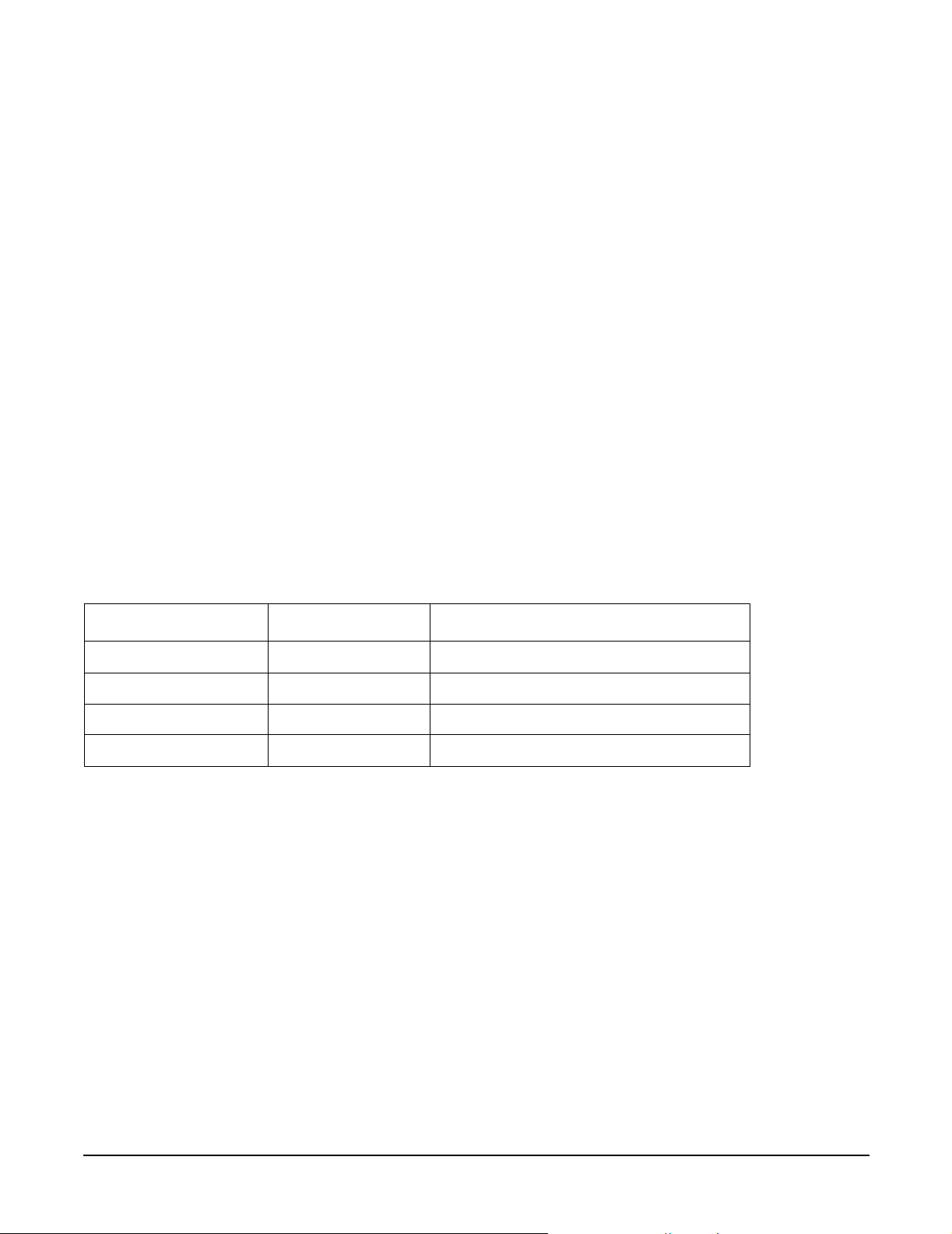
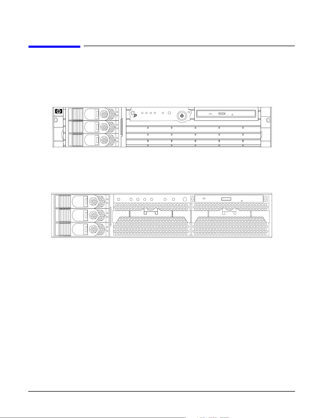
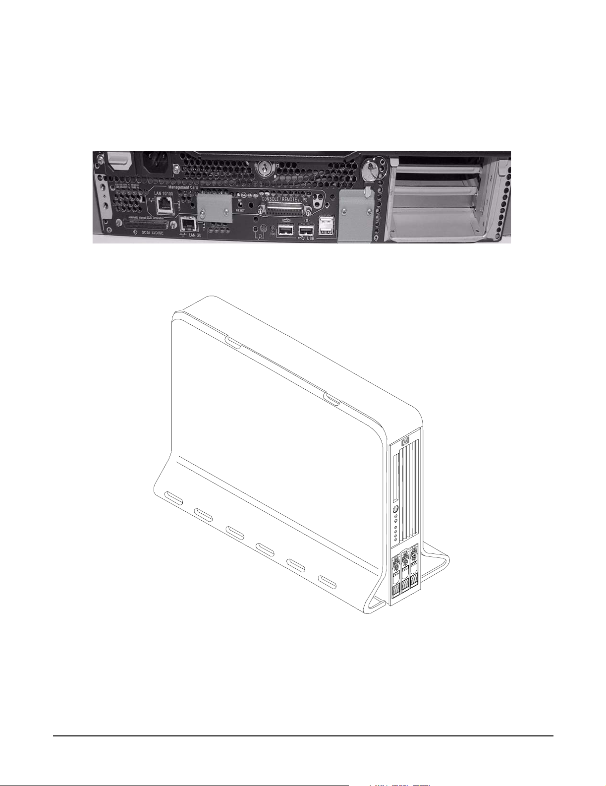
HP 9000 rp3410 and rp3440 Server Views
Figure 1-2, Figure 1-2, Figure 1-3, and Figure 1-4 show the front, rear, and pedestal views of the HP 9000
rp3410 and rp3440 servers.
Figure 1-1 HP 9000 rp3410 and rp3440 Servers - Front View
Figure 1-2 HP 9000 rp3410 and rp3440 Servers - Front View with Bezel Removed
20
Chapter 1
Page 21
HP 9000 rp3410 and rp3440 Server Views
Figure 1-3 HP 9000 rp3410 and rp3440 Servers - Rear View
Figure 1-4 HP 9000 rp3410 and rp3440 Servers - Pedestal Mount
Overview
Chapter 1
21
Page 22

Overview
Detailed Server Description
Detailed Server Description
This section provides information on the features that comprise the HP 9000 rp3410 and rp3440 servers.
Processor
The following is supported on the HP 9000 rp3410 and rp3440 servers:
• 800 MHz/1.5 GB cache (HP 9000 rp3410 and rp3440 servers).
• 1 GHz/1.5 GB cache (HP 9000 rp3440 server only).
• Both processors are available with 32 MB or 64 MB L2 cache.
• HP 9000 rp3410 servers can be 1P/1C and 1P/2C.
• HP 9000 rp3440 servers can be 1P/1C and 1P/2C, and 2P/2C.
Memory
The following is supported on the HP 9000 rp3410 and rp3440 servers:
• 12 memory DIMM slots.
• Minimum memory size is as follows:
— 512 MB (2 x 256 MB DIMMs in a HP 9000 rp3410, model A7136A server).
— 1 GB (4 x 256 MB DIMMs in a HP9000 rp3410 model A7136B server, or in a HP 9000 rp3440 server).
• Maximum memory size is as follows:
— 6 GB (HP 9000 rp3410 server), 24 GB (HP 9000 rp3440 server with 2 GB DIMMs installed in all 12
slots). or
— 32 GB (HP 9000 rp3440 server with 4 GB DIMMs installed in the first eight slots)
• For the HP 9000 rp3410 server, DIMMs are as follows:
— 256 MB, 512 MB, and 1 GB
— standard 184 pins 2.5V
— DDR266, CL2, registered, ECC
• For the HP 9000 rp3440 server, DIMMs are as follows:
— 256 MB, 512 MB, and 1 GB, 2 GB, 4 GB
— standard 184 pins 2.5V
— DDR266, CL2, registered, ECC
• Only one supported configuration for 4 GB DIMMs; 2 quads (8 DIMMs); and no other DIMMs can be
installed.
• DIMMs loaded by quads enable interleaved mode and chip spare.
• Memory is loaded across both memory busses (two DIMMs on each bus) to ensure maximum bandwidth
and performance.
• 133 MHz memory bus frequency, 266 MTransfers/s data, 8.5 GB/s peak data bandwidth.
22
Chapter 1
Page 23

Overview
Detailed Server Description
• Total memory bandwidth is 8.5 GB/s, split across two 4.25 GB/s memory buses.
• Open page memory latency is 80 nanoseconds.
PCI Riser
Two (HP 9000 rp3410 server) or four (HP 9000 rp3440 server) independent PCI-X 133 MHz 64-bit 3.3V 15W
slots. No 5V card and hot-pluggable support.
Internal Core I/O
The following is supported on the HP 9000 rp3410 and rp3440 servers:
• Dual-channel SCSI U160 interface, two internal 68-pin connectors, one 68-pin external connector.
• SCSI backplane configured either as two channels with 2+1 drives. A SAF-TE accessory (currently not
available) is required to configure the SCSI backplane as one channel with three drives.
• Three internal SCSI drive connectors are of the 80-pin type and provide drive electrical hot-pluggable
capability.
• SCSI backplane is designed to support a SCSI management piggy board accessory that provides a SCSI
management SAF-TE chip and shunts the backplane's channels A and B to provide three disks on
channel A and leave only the external connector on channel B.
• One internal IDE connector for a slim-line optical device (CD and DVD).
• No floppy connector.
External Core I/O
The following is supported on the HP 9000 rp3410 and rp3440 servers:
• One SCSI U160 68-pin connector.
• One 10/100/1000Base-T Ethernet LAN connectors for copper cable.
• Four USB 2.0 ports.
• Three DB-9 ports (console, UPS, and modem) through a 3-connector M cable.
Power Supply Unit
The following is supported on the HP 9000 rp3410 and rp3440 servers:
• 650W output power.
• The power supply is split in a front end block (the actual power supply case) that converts the line voltage
into a high dc voltage and back end voltage regulation modules (on the motherboard) that step down the
front end dc voltage to the required voltages.
• Redundant and hot-pluggable power supplies (front end block only).
System Board Manageability
The following is supported on the HP 9000 rp3410 and rp3440 servers:
• Baseboard Management Controller (BMC).
• Temperature monitoring and fans regulation by BMC.
Chapter 1
23
Page 24

Overview
Detailed Server Description
• BMC manageability console shared with system console/general purpose serial port.
• IPMI protocol for communication between BMC/system/iLO MP.
• Hardware diagnostics by BMC displayed on the front status panel.
• Locator front/rear LEDs.
• Field replacement units monitoring by BMC.
Enhanced Server Manageability Using the Integrity iLO MP
The following is supported on the HP 9000 rp3410 and rp3440 servers:
•LAN telnet console.
•Web GUI.
• Serial port for local console.
• Serial port for modem console.
• Duplication of console screen content across all consoles.
Hard Disk Drives
Three half-height hard disk drives (1-inch height).
Internal RAID
The following is supported on the HP 9000 rp3410 and rp3440 servers:
• The A9890A and A9891A RAID cards are supported to provide RAID for the embedded drives.
• The A9827A cabling kit is required for internal RAID. See the HP 9000 rp3410 and HP 9000 rp3440
Upgrade Guide for complete RAID installation instructions.
Firmware
Firmware consists of many individually linked binary images that are bound together by a single framework
at run time. Internally, the firmware employs a software database called a device tree to represent the
structure of the hardware platform and to provide a means of associating software elements with hardware
functionality.
The firmware incorporates the Boot Console Handler (BCH) which provides an interface between the
operating system and the platform firmware.
The firmware supports the HP-UX 11i version 1 (and higher HP-UX versions that support PA-RISC systems)
operating system through the HP 9000 processor family standards and extensions, and has no operating
system-specific functionality included. The operating system is presented with the same interface to system
firmware, and all features are available to the operating system.
Event IDs for Errors and Events
The server firmware generates event IDs similar to chassis codes for errors, events, and forward progress to
the Integrity Integrated Light-Out Management Processor (iLO MP) through common shared memory. The
integrity iLO MP interprets and stores event IDs. Reviewing these events helps you diagnose and
troubleshoot problems with the server.
24
Chapter 1
Page 25
Detailed Server Description
Dimensions and Values
Table 1-1 lists the dimensions and their values of the HP 9000 rp3410 and rp3440 servers.
Table 1-1 Server Dimensions and Values
Dimension Values
Overview
Rack dimensions (depth x width x height)
Pedestal dimensions (depth x width x height)
Rack weight
Pedestal weight
Pedestal footprint
Rack units 2U
26.8 in (67.9 cm) max. x 19.0 in (48.3 cm) x 3.4 in (8.6 cm)
26.6 in (67.5 cm) x 11.6 in (29.5 cm) x 19.5 in (49.4 cm)
Minimum: 38.6 lbs (17.5 kg)
Maximum: 49.0 lbs (22.2 kg)
Minimum: 49.4 lbs (22.4 kg)
Maximum: 56.3 lbs (25.5 kg)
2
0.2 m
(2.1 sq. ft.)
System Board
This section provides a block diagram of the system board and descriptions of key components (integrated
circuits) on the board.
Chapter 1
25
Page 26
Overview
Detailed Server Description
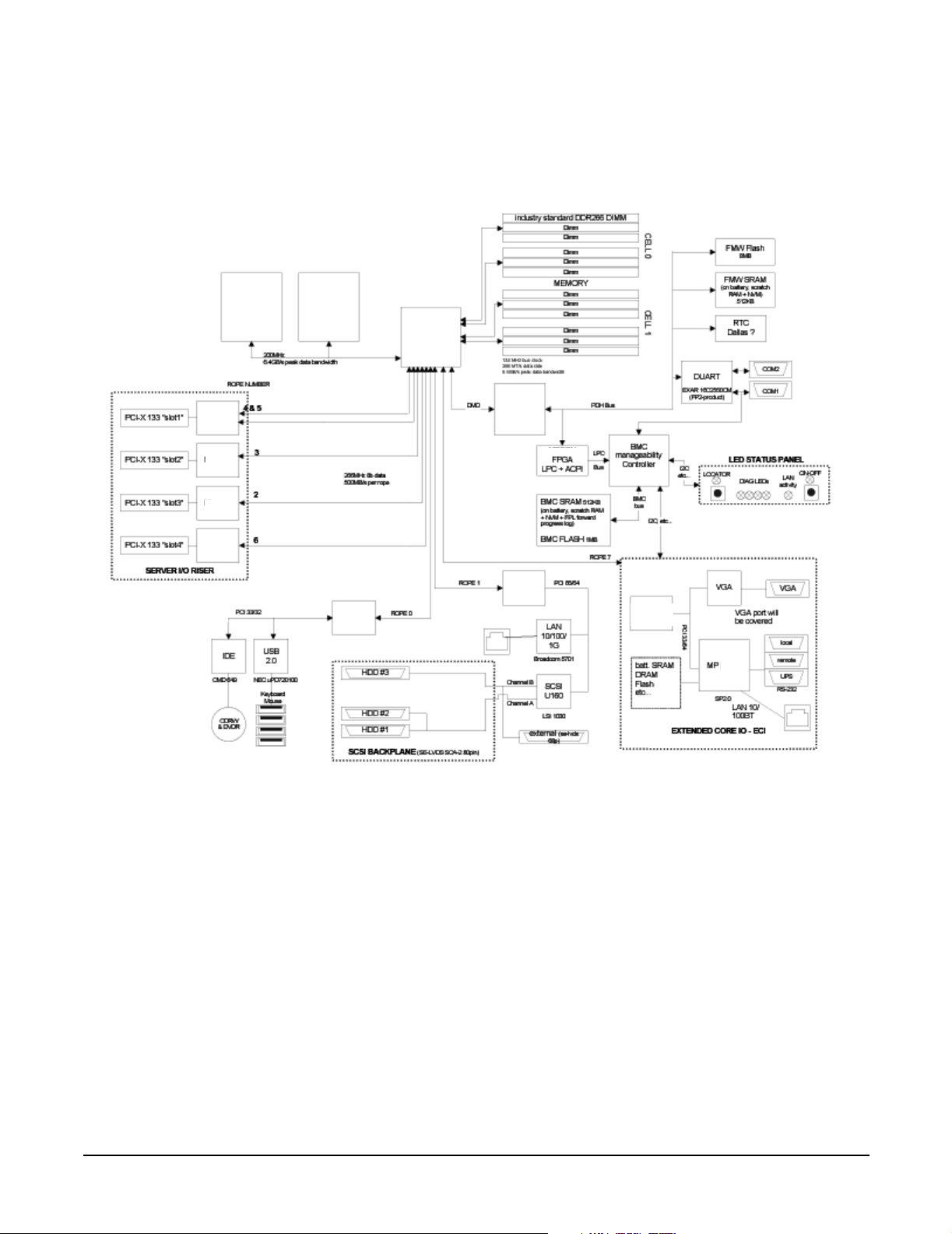
Figure 1-5 shows the system block diagram.
Figure 1-5 System Block Diagram
ASIC
Bus
Interface
ASIC
Bus
Interface
ASIC
Bus
Interface
ASIC
Bus
Interface
PA-RISC
Processor
PA-RISC
Processor
Interface
ASIC
Bus
ASIC
Bus
Interface
ASIC
Bus
Interface
ASIC
Bus
Interface
ASIC
Bus
Interface
*
*
*Factory use only
System Board Components
The following describes the main components of the system board:
• Dual PA-RISC processors:
— One or two processors enabled in HP 9000 rp3410 server
— One, two, or four processors enabled in HP 9000 rp3440 server
• ZX1 I/O and memory controller
• ZX1 PCI bus controller
• Processor dependent hardware controller
• Field processor gate array controller
•BMC
• SCSI controller
26
Chapter 1
Page 27

Overview
Detailed Server Description
• IDE controller
• USB controller
• 10/100/1000 LAN
PA RISC Processor
The system board consists of two Zero Insertion Force (ZIF) processor sockets, the Core Electronic Complex
(CEC), and circuits for clock and power generation and distribution, boundary Scan, In-target Probe (ITP),
and debug.
The Front Side Bus (FSB) is the IA64 processor bus based on bus protocol from Intel. This enables processor
customer self-repair (CSR) parts to be dropped in, provided that electrical and mechanical compatibility and
support circuitry exist. A processor CSR consists of a dual processor module with heatsink assembly.
One end of the FSB is terminated with an I/O ASIC. The other end of the bus is terminated with a CSR. An
additional CSR can be loaded in the middle. For the system to function properly, the processor farthest away
from the I/O ASIC must be loaded at all times to electrically terminate the FSB.
Each processor module plugs directly into and is powered by its own 12V to 1.2V power-pod. Other power for
the system board comes from multiple on-board dc/dc converters. Each processor module is attached to the
board through a ZIF socket and the entire CSR secured down by a heatsink bolster plate.
Processor Bus
The processor bus (Front Side Bus [FSB]) in this product runs at 200 MHz. Data on the FSB are transferred
at a double data rate, which enables a peak FSB bandwidth of 6.4 Gb/sec.
ZX1 I/O and Memory Controller
HP 9000 rp3410 and rp3440 servers support the following features of the ZX1 I/O and memory controller
chip:
• 3.3 GB/s peak IO bandwidth.
• Provides eight communication paths.
• Peak memory bandwidth of 8.5 GBs.
• Two memory cells, 144 data bits each.
Memory
The memory subsystem provides two memory cells, each of which is 144 data bits wide. Each cell has six
DIMM slots, which means a total of 12 DIMM slots are available. The memory bus clock speed is 133 MHz,
and the data transfer rate is 266Mtransfers/second as data is clocked on both edges of the clock. The peak
data bandwidth for this memory subsystem design is 8.5 GB/s. DIMMs must be loaded in quads with
qualified modules, with the exception of 256 MB DIMMs which is loaded in pairs. Memory is protected by
data error correction code (ECC), and the hardware implementation supports the chip-spare feature.
The minimum amount of memory that you can install is 512 MB (2x256 MB modules in a HP 9000 rp3410
model A7136A server), and 1 GB (4x256 MB modules in other HP 9000 rp34x0 servers). The maximum
amount of memory that you can install is limited to 24 GB (12 x 2 GB modules) or 32 GB (8 x 4 GB modules)
in a HP 9000 rp3440 server.
This design does not support any non industry-standard DDR DIMMs. Only qualified DIMMs are supported.
Chapter 1
27
Page 28
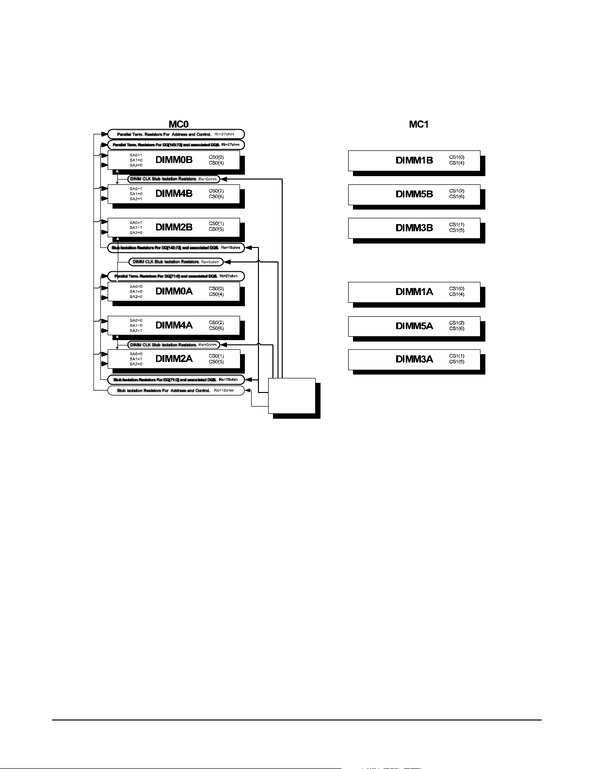
Overview
Detailed Server Description
Figure 1-6 shows the memory block diagram.
Figure 1-6 Memory Block Diagram
Memory
Controller
Memory Architecture
The I/O ASIC memory interface supports two DDR cells, each of which is 144 data bits wide. The memory
subsystem physical design uses a comb-filter termination scheme for both the data and address/control buses.
This part of the topology is similar to other DDR designs in the computer industry. Clocks are distributed
directly from the I/O ASIC; each clock pair drives two DIMMs.
Memory data is protected by ECC. Eight ECC bits per DIMM protect 64 bits of data. The use of ECC enables
correction of single-bit errors, and detection of multi-bit errors. Only DIMMs with ECC are qualified or
supported.
DIMMs
The memory subsystem only supports DDR SDRAM (Double Data Rate Synchronous Dynamic Random
Access Memory) technology utilizing industry-standard PC-1600 type DDR SDRAM DIMMs, 1.2" tall. This is
currently being used by high-volume products. The DIMMs use a 184-pin JEDEC standard connector.
DIMMs are loaded in groups of four, known as a rank or quad (except for 256 MB DIMMs, which is loaded in
pairs). All four DIMMs in a rank or quad must be the same size. The following information summarizes the
memory solutions.
28
Chapter 1
Page 29
Overview
Detailed Server Description
Memory Array Capacities
Table 1-2 lists the memory array capacities for the server.
Table 1-2 Memory Array Capacities
Minimum and
Maximum
Memory Size
0.5 GB / 3 GB 256 MB DIMM 18 x 32 MB x 4 DDR SDRAMs (128 MB)
2 GB / 6 GB 512 MB DIMM 36 x 32 MB x 4 DDR SDRAMs (128 MB)
4 GB / 12 GB 1024 MB DIMM 36 x 64 MB x 4 DDR SDRAMs (256 MB)
8 GB / 24 GB 2048 MB DIMM 36 x 128 MB x 4 DDR SDRAMs (512 MB)
16 GB / 32 GB 4096 MB DIMM 36 x 256 MB x 4 DDR SDRAMs (1024 MB)
Chip Spare Functionality
Chip spare enables an entire DDR SDRAM chip on a DIMM to be bypassed in the event that a multi-bit error
is detected on the DDR SDRAM. In order to use the chip spare functionality on the server, only DIMMs built
with ×4 DDR SDRAM parts are used, and these DIMMs must be loaded in quads.
Single DIMM Size DDR SDRAM Count, Type and Technology
The memory subsystem design supports the I/O ASIC chip’s spare functionality. Chip spare enables an entire
SDRAM chip on a DIMM to be bypassed/replaced in the event that a multi-bit error is detected on that
SDRAM. In order to use the chip spare functionality, only DIMMs built with x4 SDRAM parts are used, and
these DIMMs must be loaded in quads (2 DIMMs per memory cell, loaded in the same location in each
memory cell). Each DIMM within a quad must be identical to all the other DIMMs in the quad.
Using the DIMM loading order figure from above, chip spare is achieved if four identical DIMMs are loaded in
the slots labeled “1st” and “2nd.” If more DIMMs are added, they must be loaded in quads in order to
maintain the chip spare functionality. If more DIMMs are added to the example case, four identical DIMMs
(identical to each other, but can be different from the original quad that was loaded) must be loaded in the
slots labeled “3rd” and “4th.”
Maximum memory capability of the HP 9000 rp3440 server is 24 GB or 32 GB. If 4 GB DIMMs are used,
install eight DIMMs in the first eight slots. The remaining slots (9-12) must remain empty when 4 GB
DIMMs are used.
Serial Presence Detect
Each DIMM contains an I
2
C EEPROM whose content describes the module’s characteristics: speed,
technology, revision, vendor, etc. This feature is called serial presence detect (SPD). Firmware typically uses
this information to detect unmatched pairs of DIMMs, and configure certain memory subsystem parameters.
The SPD information for DIMMs loaded in the system are also accessible to the BMC through the I
2
C bus.
I/O Bus Interface
The I/O bus interface has these features:
• Provides industry standard PCI 33 MHz and 66 MHz, PCI-X 66 MHz to 133 MHz, 32 or 64 data bit
support.
• Uses 3.3V PCI only, and it does not support 5V PCI.
• Optimizes for DMA performance.
Chapter 1
29
Page 30

Overview
Detailed Server Description
• Supports 3.3V or universal-keyed PCI cards. 5V-keyed PCI cards are not supported.
Processor Dependent Hardware (PDH) Controller
The Processor Dependent Hardware (PDH) controller provides the following features.
• 16-bit PDH bus with reserved address space for the following:
—Flash memory
— Nonvolatile memory
— Scratch RAM
— Real time clock
— UARTs
— External registers
— Firmware read/writable registers
— Two general purpose 32-bit registers
— Semaphore registers
— Monarch selection registers
— Test and reset register
• Reset and INIT generation
Field Programmable Gate Array
The Field Programmable Gate array (FPGA) provides ACPI and LPC support for the PDH bus and provides
these features:
• ACPI 2.0 interface.
• LPC bus interface to support BMC.
• Decoding logic for PDH devices.
BMC
The BMC supports the industry-standard Intelligent Platform Management Interface (IPMI) specification.
This specification describes the management features that have been built into the system board. These
features include: diagnostics (both local and remote), console support, configuration management, hardware
management and troubleshooting.
The BMC provides the following:
• Compliance with IPMI 1.0.
• Tachometer inputs for fan speed monitoring.
• Pulse width modulator outputs for fan speed control.
• Push-button inputs for front panel buttons and switches.
• One serial port, multiplexed with the system console port.
• Remote access and intelligent chassis management bus (ICMB) support.
•Three I
2
C master/slave ports (one of the ports is used for intelligent platform management bus (IPMB).
30
Chapter 1
Page 31

Overview
Detailed Server Description
• Low Pin Count (LPC) bus provides access to three Keyboard Controller Style (KCS) and one-Block
Transfer (BT) interface.
• 32-bit ARM7 RISC processor.
• 160-pin Low Profile Flat Pack (LQFP) package.
• Firmware is provided for the following interfaces:
—IPMI
—IPMB
SCSI Controller
The SCSI controller is a LSI Logic 53C1030 chip. This chip is fully compliant with the SCSI Peripheral
Interface-4 Specification (SPI-4). It has two independent SCSI channels supporting devices at speeds up to
320 MB/sec each. The 53C1030 adheres to the PCI-X addendum, to the PCI Local Specification, and is
hard-wired to PCI ID 1 which corresponds to bit 17 of the PCI AD bus.
IDE Interface
The IDE controller (PCI649) supports the ATAPI zero (0) to five (5) modes (from 16 to 100 MB/s). The usable
speed on this system is limited to 16 MHz (ATA-33 mode, 33 MB/s) because the slimline CD/DVD devices do
not support the ATA-66 and 100 modes.
The primary IDE channel is the only channel that is implemented. The IDE cable provides only one drive
connector, of the master type, for the optical storage peripheral.
1 GB System LAN
The 1 GB System LAN port provides:
• Main system LAN.
• 10/100/1000 MB capable.
USB Connectors
The USB connectors provide:
• High speed 480 MB/sec. capable.
• Full speed 12 MB/sec. and low speed 1.5 MB/sec.
• Support for USB keyboard and mouse.
• HP-UX supports HP USB keyboard and mouse.
Chapter 1
31
Page 32

Overview
Detailed Server Description
Disk and I/O Path Logging
Some failures result in I/O path logging. These paths help to indicate the source of the error and can be
included in the error message or logged into console or event logs.
Table 1-3 describes the disk drive and DVD paths for the server.
Table 1-3 Internal Disk and DVD Paths
Function
Slot
Disk slot 0 Ultra 3 SCSI I/O for bottom removable disk Bottom disk slot 0/1/1/0.0.0
Disk slot 1 Ultra 3 SCSI I/O for middle removable disk Middle disk slot 0/1/1/0.1.0
Disk slot 2 Ultra 3 SCSI I/O for top removable disk Top disk slot 0/1/1/1.2.0
DVD slot IDE I/O for DVD DVD slot 0/0/2/0.0.0
Table 1-4 describes the extended core I/O paths for the server.
Associated
with Path
Location ACPI Path
Table 1-4 Extended Core I/O Paths
Function
Slot
Core I/O USB port Rear panel (with
Core I/O USB port 0/0/1/0 Rear panel (top/
Core I/O USB port Rear panel (with
Core I/O USB port Rear panel (bottom/
Core I/O USB port Internal 0/0/1/2
Core I/O IDE controller System board 0/0/2/0
Core I/O LAN 100 port Rear panel (with
Core I/O Ultra 3 SCSI Channel A System board 0/1/1/0
Core I/O Ultra 3 SCSI Channel B System board 0/1/1/1
Core I/O Ultra 3 SCSI I/O— external SCSI Rear panel (with
Associated
with Path
Location‘ ACPI Path
0/0/1/0
mouse symbol)
white connector)
0/0/1/1
keyboard symbol)
0/0/1/1
white connector)
0/0/3/0
LAN 10/100 label)
0/1/1/1.x.y
“SCSI LVD/SE”
label)
Core I/O LAN 1000 port Rear panel (with
LAN GV label)
32
0/1/2/0
Chapter 1
Page 33

Table 1-4 Extended Core I/O Paths (Continued)
Function
Slot
Associated
with Path
Overview
Detailed Server Description
Location‘ ACPI Path
Console port Interface with external console (ECI) Rear panel
(accessible thru W
cable)
Remote port Interface with UPS (ECI) Rear panel
(accessible thru W
cable)
UPS port Interface with UPS Rear panel
(accessible thru W
cable)
ECI
(VGA port)
N/A Baseboard console port (CLI) Rear panel (with
N/A Baseboard serial port Rear panel (with
Table 1-5 describes the PCI I/O paths for the server.
Not used (disabled) Rear panel (with
VGA label)
Serial A label)
Serial B label)
Table 1 -5 P C I I/ O Pat h s
Function
Slot
Associated
with Path
Location‘ ACPI Path
0/7/1/1
0/7/1/0
N/A
0/7/2/0
Factory use only
Factory use only
Slot 1 64-bit, 133 MHz PCI-X card Top connector/slot in
PCI card cage
Slot 2 64-bit, 133 MHz PCI-X card Second
connector/slot in
PCI card cage
Slot 3 64-bit, 133 MHz PCI-X card (active rp3440 only) Third connector/slot
in PCI card cage
Slot 4 64-bit, 133 MHz PCI-X card (active rp3440 only) Bottom connector of
PCI card cage
Table 1-6 describes the PCI I/O hardware paths for the server
Table 1-6 PCI I/O Hardware Paths
PCI Card Functionality MAPPER Path HP-UX Path
USB Port 0/0/1/0 0/0/1/0
USB Port 0/0/1/0 0/0/1/0
Chapter 1
0/4/1/0
0/3/1/0
0/2/1/0
0/6/1/0
33
Page 34

Overview
Detailed Server Description
Table 1-6 PCI I/O Hardware Paths (Continued)
PCI Card Functionality MAPPER Path HP-UX Path
USB Port 0/0/1/1 0/0/1/1
USB Port 0/0/1/1 0/0/1/1
IDE Controller 0/0/2/0 0/0/2/0
DVD Drive 0/0/2/0.0.0 0/0/2/0.0.0
Internal SCSI - Slot 0 0/1/1/0.0.0 0/1/1/0.0.0
Internal SCSI - Slot 1 0/1/1/0.1.0 0/1/1/0.1.0
Internal SCSI - Slot 2 0/1/1/1.2.0 0/1/1/1.2.0
Channel A Ultra 3 SCSI 0/1/1/0 0/1/1/0
Channel B Ultra 3 SCSI 0/1/1/1 0/1/1/1
External, Ultra 3 SCSI LVD/SE 0/1/1/1.x.y 0/1/1/1.x.y
Core LAN Gb 0/1/2/0 0/1/2/0
PCI Slot 1 0/4/1/0 0/4/1/0
PCI Slot 2 0/3/1/0 0/3/1/0
PCI Slot 3 0/2/1/0 0/2/1/0
PCI Slot 4 0/6/1/0 0/6/1/0
UPS, Communications Controller 0/7/1/0 0/7/1/0
Local/Remote Serial Controller 0/7/1/1 0/7/1/1
34
Chapter 1
Page 35

Overview
Controls, Ports, and LEDs
Controls, Ports, and LEDs
This section describes the controls, ports, and indicators found on the front and rear panel locations of the HP
9000 rp3410 or rp3440 server. The servers are designed to be rack- or pedestal-mounted.
Control Panel
The control panel of the HP 9000 rp3410 and rp3440 servers provide the controls and indicators commonly
used for operation.
Figure 1-7 shows the front panel details.
Figure 1-7 Front View
Control Panel DVD Drive
Drive 3
Drive 2
Drive 1
System Product
Label (Pulls-Out)
Figure 1-8 shows the control panel LEDs and buttons.
Figure 1-8 Control Panel LEDs and Buttons
Locator Button and LED
Diagnostics LEDs
(Disabled)
LAN
LED
1 2 3 4 LAN System
System
LED
Power Button
Power On/Off LED
Chapter 1
35
Page 36

Overview
Controls, Ports, and LEDs
Table 1-7 provides control panel and LED information.
Table 1-7 Control Panel LEDs and Switches
Name Function
Power on/off
LED
Power Button Controls the power supply (turns system power on or off) if power is available to the
The green on/off LED is illuminated when the power is on.
power supply. (Controls both power supplies if two are installed).
If power is off but power is available to the power supplies, pressing the power button
does the following:
• Momentarily (less than one second) turns on the power supplies and applies power to
server circuits.
• More than two or three seconds, then released, has no effect.
If power is on and the system is at initial system loader, pressing the power button:
• Momentarily (less than one second) has no effect.
• More than one second, but less than five seconds—do not use. This initiates e-buzzer
functions that are not supported in the server.
• More than five seconds then released causes an immediate hard power off.
If power is on and the system is at BCH, pressing the power button does the following:
• Momentarily (less than one second) causes a immediate and hard power down.
• More than one second, but less than five seconds—do not use. This initiates e-buzzer
functions that are not supported in the server.
• More than five seconds then released causes an immediate hard power off.
If power is on but the OS has been shut down, pressing the power button:
• Momentarily (less than one second) has no effect.
• More than one second, but less than five seconds—do not use. This initiates e-buzzer
functions that are not supported in the servers.
• More than five seconds then released causes an immediate hard power off.
If the OS is running, pressing the power button does the following:
• Momentarily (less than one second) has no effect.
• More than one second, but less than five seconds—do not use. This initiates e-buzzer
functions that are not supported in the servers.
• More than five seconds then released causes an immediate hard power off.
System LED The System LED provides information about the system status. When operation is
normal, the LED is green. When there is a system warning, the LED is flashing yellow.
When there is a system fault, the LED is flashing red.
LAN LED The LAN LED provides status information about the LAN interface. When the LAN LED
is flashing, there is activity on the LAN.
36
Chapter 1
Page 37
Table 1-7 Control Panel LEDs and Switches (Continued)
Name Function
Overview
Controls, Ports, and LEDs
Locator button
and LED
The locator button and LED are used to help locate this server within a rack of servers.
When the button is engaged, the blue LED illuminates and an additional blue LED on
the rear panel of the server illuminates. You can remotely activate this function.
Additional Controls and Indicators
HP 9000 rp3410 and rp3440 servers can have up to three low-voltage differential (LVD), 3.5-inch form factor
hot-pluggable disk drives installed. These disk drives have LEDs that provide status and activity
information.
Hot-Pluggable Disk Drive Indicators
The disk drives have two LEDs per drive, as follows:
• Status LED: Not used on the HP 9000 rp3410 or rp3440 server.
• Activity LED: Flashing green and indicates disk drive activity. This LED is directly controlled by the disk
drive and turns on when a drive is accessed.
Figure 1-9 shows the hot-pluggable disk drive LED indicators.
Figure 1-9 Hot-Pluggable Disk Drive LED Indicators
Status LED
(Not Used)
Activity LED
Table 1-8 lists the hot-pluggable disk drive LED definitions.
Table 1-8 Hot-Pluggable Disk Drive LED Definitions
LED State Description
Status LED None Not used.
Activity LED Flashing green Reading and scanning hard drive
Optional Removable Media Drive
HP 9000 rp3410 and rp3440 servers are delivered without a removable media drive. You can add either a
DVD or CD-RW/DVD drive. Each of these optional devices has one activity LED.
Chapter 1
37
Page 38
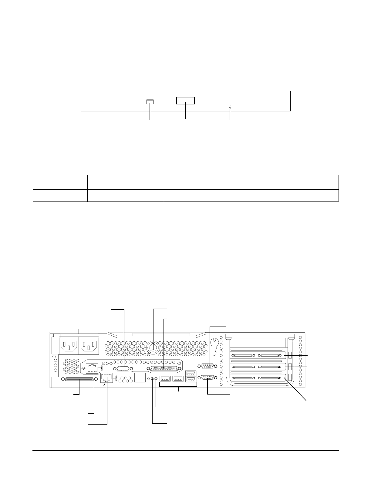
Overview
Controls, Ports, and LEDs
Figure 1-10 shows the DVD drive details.
Figure 1-10 DVD Drive
DVD
Activity LED
Table 1-9 lists the DVD drive LED definitions.
Eject Button
Emergency Eject
Table 1-9 DVD Drive LED Definitions
LED State Description
Activity LED Flashing green Drive is active
Rear Panel
The rear panel of the HP 9000 rp3410 and rp3440 servers includes communication ports, I/O ports, ac power
connector, and the locator LED/button. Additional LEDs located on the rear panel of the HP 9000 rp3410 and
rp3440 servers signal the operational status of:
• 10/100/1000 Base-T Ethernet LAN
• iLO MP card LAN
Figure 1-11 shows the rear panel ports and LEDs.
Figure 1-11 Rear View
VGA Port-disabled
ac Power Receptacle
LVD/SE SCSI
10/100 iLO MP
10/100/1000 LAN
38
DO NOT USE
LAN
System Lock
Console/Remote/UPS
USB Ports
TOC Button
Locator Button and LED
Console/Serial Port A (Factory Use Only)
PCI Slot 1
PCI Slot 2
PCI Slot 3
(rp3440
Only)
Serial Port B
(Factory Use Only)
PCI Slot 4
(rp3440
Only)
Chapter 1
Page 39

Table 1-10 lists the rear-panel connectors and switches.
Table 1-10 Rear Panel Connectors and Switches
Overview
Controls, Ports, and LEDs
Connector or
Switch
ac power Primary power connection for the server.
LVD/SE SCSI 68-pin, low-voltage differential, single-ended U160 SCSI. This connector provides
external SCSI connection on SCSI Channel B.
(1 GB) 10/100/1000
LAN
Serial A (console)
and Serial B
USB Four universal serial bus (USB 2.0) connectors.
TOC Transfer of control button. Halts all system processing and I/O activity and
Locator button and
LED
Video (not used) 15-pin female video connector. DISABLED—DO NOT USE. To enable video
10/100/1000 base-T Ethernet LAN connector.
9-pin male serial connectors—factory use only.
restarts system.
The locator button and LED are used to help locate a server within a rack of
servers. When the button is engaged, the blue LED illuminates and an additional
blue LED on the front panel of the server illuminates. You can remotely activate
this function.
capability you must obtain the supported A6150 video PCI card. See enclosed
ReadMe, A6150-90001.
Function
Console/remote/UPS 25-pin female serial data bus connector for the iLO MP card.
10/100 iLO MP LAN 10 Mb/100 Mb LAN connector for the iLO MP.
10/100/1000 Base-T Ethernet LAN Connector
Figure 1-12 shows the rear panel 10/100/1000 base-T Ethernet LAN connector and the status and activity
LEDs.
Figure 1-12 10/100/1000 Base-T Ethernet LAN Connector LEDs
1 2 3 4 5 6 7 8
1000BT
100BT
10BT
Activity
Chapter 1
39
Page 40

Overview
Controls, Ports, and LEDs
Table 1-11 lists the 10/100/1000 base-T Ethernet LAN connector LED descriptions.
Table 1-11 10/100/1000 Base-T Ethernet LAN Connector LEDs
LED Description
1000BT Blinking green—the 1000 MHz with Ethernet protocol and twisted-pair wiring is
enabled, off—no link.
100BT Blinking green—the 100 MHz with Ethernet protocol and twisted-pair wiring is
enabled, off—no link.
10BT Blinking green—the 10 MHz with Ethernet protocol and twisted-pair wiring is
enabled, off—no link.
Activity Blinking green—LAN activity.
Table 1-12 lists the 10/100/1000 base-T Ethernet LAN connector pinouts.
Table 1-12 10/100/1000 Base-T Ethernet LAN Connector Pinouts
Pin Number Signal Description
1TXP
2TXN
3RXP
4Not used
5Not used
6RXN
7Not used
8Not used
USB Ports
Figure 1-13 shows the dual USB port connector.
Figure 1-13 Dual USB Port Connector
1 2
34
40
1 2
34
Chapter 1
Page 41

Figure 1-14 shows the single USB port.
Figure 1-14 Single USB Port
Table 1-13 lists the USB pinouts.
Table 1 -13 U S B Pin o uts
Pin Number Signal Description
1+5 VDC
1 2
Overview
Controls, Ports, and LEDs
34
2MR
3PR
4 Ground
SCSI Port, Ultra 3, 68-Pin
A single, Ultra 3, 68 pin SCSI connector is located at the rear panel of the server. The external connector
supports SCSI channel “B.”
Figure 1-15 shows the SCSI port, Ultra 3, 68-pin.
Figure 1-15 SCSI Port, Ultra 3, 68-Pin
35
1
Table 1-14 lists the SCSI port pinouts.
68
34
Table 1 -14 S C SI Port Pi n outs
Pin Number Signal Description Pin Number Signal Description
1 S1 (+DB 12) 35 S35 (–DB 12)
2 S2 (+DB 13) 36 S36 (–DB 13)
Chapter 1
41
Page 42

Overview
Controls, Ports, and LEDs
Table 1-14 SCSI Port Pinouts (Continued)
Pin Number Signal Description Pin Number Signal Description
3 S3 (+DB 14) 37 S37 (–DB 14)
4 S4 (+DB 15) 38 S38 (–DB 15)
5 S5 (+DB P1) 39 S39 (–DB P1)
6 S6 (+DB 0) 40 S40 (–DB 0)
7 S7 (+DB 1) 41 S41 (–DB 1)
8 S8 (+DB 2) 42 S42 (–DB 2)
9 S9 (+DB 3) 43 S43 (–DB 3)
10 S10 (+DB 4) 44 S44 (–DB 4)
11 S11 (+DB 5) 45 S45 (–DB 5)
12 S12 (+DB 6) 46 S46 (–DB 6)
13 S13 (+DB 7) 47 S47 (–DB 7)
14 S14 (+DB P) 48 S48 (–DB P)
15 S15 49 S49
16 S16 (DIFFSENS) 50 S50
17 S17 (TERMPWR) 51 S51 (TERMPWR)
18 S18 (TERMPWR) 52 S52 (TERMPWR)
19 S19 (RESERVED) 53 S53 (RESERVED)
20 S20 54 S54
21 S21 (+ATN) 55 S55 (–ATN)
22 S22 56 S56
23 S23 (+BSY) 57 S57 (–BSY)
24 S24 (+ACK) 58 S58 (–ACK)
25 S25 (+RST) 59 S59 (–RST)
26 S26 (+MSG) 60 S60 (–MSG)
27 S27 (+SEL) 61 S61 (–SEL)
28 S28 (+C/D) 62 S62 (–C/D)
29 S29 (+REQ) 63 S63 (–REQ)
30 S30 (+I/O) 64 S64 (–I/O)
31 S31 (+DB 8) 65 S65 (–DB 8)
42
Chapter 1
Page 43
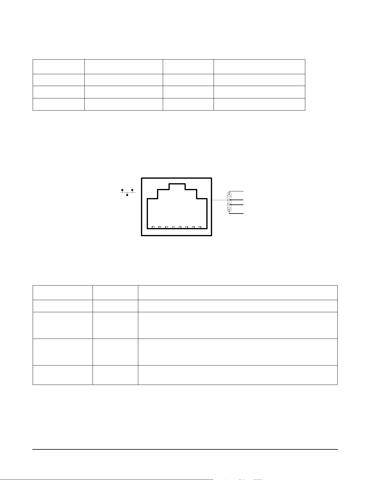
Overview
Controls, Ports, and LEDs
Table 1-14 SCSI Port Pinouts (Continued)
Pin Number Signal Description Pin Number Signal Description
32 S32 (+DB 9) 66 S66 (–DB 9)
33 S33 (+DB 10) 67 S67 (–DB 10)
34 S34 (+DB 11) 68 S68 (–DB 11)
iLO MP Card LAN LEDs
The iLO MP card LAN uses an RJ-45 type connector. This connector has four LEDs that signal status and
activity.
Figure 1-16 shows the iLO MP card LAN LEDs.
Figure 1-16 iLO MP Card LAN LEDs
Self-test
10BT
100BT
Standby
Power
Table 1-15 lists the iLO MP card LAN LEDs.
Table 1-15 iLO MP Card LAN LEDs
LED Color Description
Self-test Yellow iLO MP is running self-test or error is detected
10BT Green 10BT link established, blinking green
10BT link activity, off
no link
100BT Green 100BT link established, blinking green
100BT link activity, off
no link
Standby power Green Standby power on, off
standby power off
Chapter 1
43
Page 44

Overview
Powering the Server On and Off
Table 1-16 lists the iLO MP card LAN connector pinouts.
Table 1-16 iLO MP Card LAN Connector Pinouts
Pin Number Signal Description
1TXP
2TXN
3RXP
4Not used
5Not used
6RXN
7Not used
8Not used
Powering the Server On and Off
This section provides information on how to power off and power on the server.
Power States
The server has three power states:
•Standby power
•Full power
•Off
Plug the power cord into the appropriate receptacle on the rear of the server to achieve the standby power
state; the front panel power button is not turned on. Full power occurs when the power cord is plugged into
the appropriate receptacle, and either the power is activated through the iLO MP PC command, or the power
button is activated. In the off state, the power cords are not plugged in.
Table 1-17 lists the server power states.
Table 1-17 Power States
Power Activated through the
iLO MP PC Command; or
Front Panel Power Button
Activated?
Standby dc
Voltage
Applied?
dc Voltage
Applied?
Power States
Power Cable
Plugged Into
Receptacle?
Standby power Yes No Yes No
Full power Yes Yes Yes Yes
Off No No No No
44
Chapter 1
Page 45

Overview
Powering the Server On and Off
NOTE If the power restore feature is set to Always On through the iLO MP PR command, the server
automatically powers on to the full power state.
Powering On the Server
Power on the server to full power using the following methods if the server is in the standby power state:
•iLO MP PC command
• Power button
Powering On the Server Using the iLO MP
NOTE If the power restore feature is set to Always On through the iLO MP PR command, the server
automatically powers on to the full power state.
To power on the server using the iLO MP, follow these steps:
Step 1. Plug all power cables into the receptacles on the rear panel of the server.
Step 2. Initiate a console session, and access the
Step 3. Enter CM to enable command mode.
Step 4. Enter PC to use the remote power control command.
Step 5. Enter ON to power on the server, and enter YES when prompted to confirm the action.
Step 6. Start the operating system.
Powering On the Server Manually
NOTE If the power restore feature is set to Always On through the iLO MP PR command, the server
automatically powers on to the full power state.
To manually power on the server, follow these steps:
Step 1. Plug all power cables into the receptacles on the rear panel of the server.
Step 2. Press the power button to start the server.
Step 3. Start the operating system.
MP Main Menu.
Powering Off the Server
Power off the server using the following methods if the server is in the standby or full power state:
•iLO MP PC command
• Power button
Powering Off the Server Using the iLO MP
To power off the server using the iLO MP, follow these steps:
Chapter 1
45
Page 46

Overview
Powering the Server On and Off
Step 1. Gracefully shut down the operating system.
Step 2. Initiate a console session, and access the
MP Main Menu.
Step 3. Enter CM to enable command mode.
Step 4. Enter PC to use the remote power control command.
Step 5. Enter OFF to power off the server, and enter YES when prompted to confirm the action.
IMPORTANT The main dc voltage is now removed from the system; however, ac voltage for
standby power is still present in the server.
Step 6. Unplug all power cables from the receptacles on the rear panel of the server.
Powering Off the Server Manually
To manually power off the server, follow these steps:
Step 1. Gracefully shut down the operating system.
Step 2. Press the power button to power off the server.
IMPORTANT The main dc voltage is now removed from the system; however, ac voltage for
standby power is still present in the server.
Step 3. Unplug all power cables from the receptacles on the rear panel of the server.
46
Chapter 1
Page 47

2 System Specifications
This chapter provides information on the basic system configuration, physical specifications, and
requirements for the HP 9000 rp3410 or rp3440 server.
This chapter addresses the following topics:
• “System Configuration” on page 47
• “Dimensions and Values” on page 48
• “Grounding” on page 49
• “Electrical Specifications” on page 49
• “Environmental Specifications” on page 51
• “Physical and Environmental Specifications” on page 54
System Configuration
Table 2-1 lists the minimum and maximum configuration options for the HP 9000 rp3410 and rp3440 servers.
Table 2-1 Minimum and Maximum System Configurations
Component rp3410 rp3440
Microprocessors One dual processor module with one or
two PA RISC processors enabled. Each
processor is 800 MHz/1.5 MB cache
with 32 MB or 64 MB L2 cache.
Memory Supports up to 12 double data rate
(DDR) registered ECC memory, in
PC2100 DIMMs. Maximum memory
capacity is 6 GB. Supported DDR
DIMM sizes: 256 MB, 512 MB, and 1
GB.
HDDs Three 36 GB, 15K RPM Ultra320 SCSI
hot-plug disks or
Three 73 GB, 15K RPM Ultra320 SCSI
hot-plug disks or
Three 146 GB, 10K RPM Ultra320
SCSI hot-plug disks.
One or two dual processor modules each
containing two PA RISC processors.
Each processor is 800 MHz/1.5 MB cache
or 1 GHz/1.5 MB with 32 MB or 64 MB
L2 cache.
Supports up to 12 double data rate
(DDR) registered ECC Memory, in
PC2100 DIMMs. Maximum memory
capacity is 32 GB if 4 GB DIMMs are
used. Supported DDR DIMM sizes:
256 MB, 512 MB, 1 GB, 2 GB, and 4 GB.
Three 36 GB, 15K RPM Ultra320 SCSI
hot-plug disks or
Three 73 GB, 15K RPM Ultra320 SCSI
hot-plug disks or
Three 146 GB, 10K RPM Ultra320 SCSI
hot-plug disks.
SCSI Integrated Ultra-3 SCSI dual-channel
controller; 80 MB/s transfer rate with
one internal 68-pin connector and one
external 68-pin connector.
LAN PCI GB, fast Ethernet controller. PCI GB, fast Ethernet controller.
Chapter 2
Integrated Ultra-3 SCSI dual-channel
controller; 80 MB/s transfer rate with
one internal 68-pin connector and one
external 68-pin connector.
47
Page 48

System Specifications
Dimensions and Values
Table 2-1 Minimum and Maximum System Configurations (Continued)
Component rp3410 rp3440
PCI slots Two 64-bit PCI-X slots, 133 MHz, 3.3V
slots.
Core I/O One serial port, four USB 2.0 ports,
integrated RJ-45 LAN on iLO MP card.
DVD None. IDE interface; 48x speed.
External storage Optional. Optional.
Power supply One 650W power supply. You can
install a second power supply to provide
redundant (N+1) capability.
Four 64-bit PCI-X slots, 133 MHz, 3.3V
slots.
One serial port, four USB 2.0 ports,
integrated RJ-45 LAN on iLO MP card.
One 650W power supply. You can install
a second power supply to provide
redundant (N+1) capability.
Dimensions and Values
Table 2-2 lists dimensions and their values of the HP 9000 rp3410 and rp3440 servers.
Table 2-2 Server Dimensions and Values
Dimension Values
Rack dimensions (depth x width x height)
26.8 in (67.9 cm) max. x 19.0 in (48.3 cm) x3.4 in (8.6 cm)
Pedestal dimensions (depth x width x height)
Rack weight
Pedestal weight
Pedestal footprint
Rack units 2U
26.6 in (67.5 cm) x 11.6 in (29.5 cm) x 19.5 in (49.4 cm)
Minimum: 38.6 lbs (17.5 kg)
Maximum: 49.0 lbs 22.2 kg
Minimum: 49.4 lbs 22.4 kg
Maximum: 56.3 lbs 25.5 kg
0.2 m
2
(2.1 sq. ft.)
48
Chapter 2
Page 49

System Specifications
Grounding
Grounding
The site building shall provide a safety ground or protective earth for each ac service entrance to all cabinets.
Install a PE (protective earthing) conductor that is identical in size, insulation material, and thickness to the
branch-circuit supply conductors. The PE conductor must be green with yellow stripes. The earthing
conductor is to be connected from the unit to the building installation earth or, if supplied by a separately
derived system, at the supply transformer or motor-generator set grounding point.
Electrical Specifications
This section provides electrical specifications for the server.
AC Power Cords
Table 2-3 lists the power cables available for use with the HP 9000 rp3410 and rp3440 servers.
Table 2-3 Power Cords
Part Number Description Country
8120-5341 Power Cord C15/S Africa 2.5m black CA ASSY 917 South Africa
8120-1351 Power Cord C13/BS-1363 2.3m black CA ASSY 900 United Kingdom
Hong Kong
Singapore
8120-1369 Power Cord C13/AS-3112 2.0m gray CA ASSY 901 Australia
8120-1689 Power Cord C13/CEE 7 2.0m black CA ASSY 902 Europe
8120-2104 Power Cord C13/SEV 12 2.0m black CA ASSY 906 Switzerland
8120-6814 Power Cord OPT-912 3-COND 2.25-M-LG 912 Denmark
8120-0698 Power Cord C13/6-15P 0.0m black CA ASSY 904 / 918 North America (250#V)
Japan
8120-6800 Power Cord OPT-919 3-COND 2.3-M-LG 919 Israel
8120-8390 Power Cord C15/CEI 23-16 2.5m black CA ASSY 920 Argentina
8120-8389 Power Cord C15/CEI 23-16 2.5m black CA ASSY 921 Chile
8120-8376 Power Cord C13/GB-1002 2.236m gray CA ASSY 922 China
8121-0668 Power Cord OPT-927 3-COND 2.3-M-LG FLNT 927 South America
8120-6514 C13/C14 Jumper cord All
Chapter 2
49
Page 50

System Specifications
Electrical Specifications
Circuit Breaker
The marked electrical for the server is 7.2 amps. The recommended circuit breaker size is 12 amps per line
cord (2 maximum) for North America. For countries outside North America, consult the local electrical
authority that has jurisdiction for the recommended circuit breaker size.
System Power Specifications
Available power (output) is the maximum dc power that the power supply can supply to the system.
Maximum input power is what the power supply requires from the ac line to deliver the maximum dc output
(given worst case efficiency and max loading).
Maximum input current is the worst case or highest current given the lowest input voltage and the maximum
input power.
Table 2-4 lists the system power specifications.
Table 2-4 System Power Specifications
Parameter Total Rating
Input voltage 100 – 240 VAC Off Off
Input current (max) 7.2A at 115 VAC or
3.6A at 220 VAC
Input frequency 50 to 60 Hz Off Off
Measured input power 560W Off Off
Available power (output) 650W Off 85W total for PCI sockets
Maximum current at +12V 49A 0.5A Off
Maximum current at –12V 0.35A Off 0.1A
Maximum current at +3.3V 34A Off 4.6A
Maximum current at +5V 18A 31A 3A
Maximum current at +3.3V
standby
If an overload triggers the power supply overload protection, the system is immediately powered off. To reset
the power supply unit, follow these steps:
3.5A Off Off
Peak
(15 sec)
Off Off
Max. per PCI-X Sockets
64-bit, 133 MHz
1. Disconnect the power cord.
2. Determine what caused the overload by contacting a HP support representative.
3. Reconnect the power cord, then reboot the system.
If an overload occurs twice, there is an undetected short circuit somewhere.
When you use the front panel’s power button to power off the server, power consumption falls below the low
power consumption, but doesn’t reach zero. To reach zero power consumption in “off” mode, either unplug the
server or use a power block with a switch.
50
Chapter 2
Page 51
System Specifications
Environmental Specifications
Power and Cooling
Typical power consumption for a server is 600W/2050 Btu/h. The power consumptions listed in Table 2-5 are
valid for a standard configuration as shipped (one 1 GHz processor, 6 GB of memory, 650W power supply,
three hard disk drives, one graphics card, one LVD SCSI card).
All information in this section is based on primary power consumptions.
Table 2-5 lists additional component power consumption information.
Table 2-5 Additional Component Power Consumption
Additional Component Power Consumption
Processor 130W 443.6 Btu/h
SCSI hard disk drive (with I/O access) 23W 78.4 Btu/h
SCSI hard disk drive (idle) 16W 54.5 Btu/h
PCI card 10W to 25W 34.12 Btu/h to 85.30 Btu/h
Environmental Specifications
This section provides the temperature and humidity requirements, noise emission, and air flow specifications
for the server.
Operating temperature and humidity ranges might vary depending on the installed mass storage devices.
High humidity levels can cause improper disk operation. Low humidity levels can aggravate static electricity
problems and cause excessive wear of the disk surface.
Table 2-6 lists the environmental specifications for a system processing unit with a hard disk drive.
Table 2-6 Environmental Specifications
Parameter Value
Operating temperature +5°C to +35°C (+40°F to +95°F)
Storage temperature –40°C to +70°C (–40°F to +158°F)
Over-temperature shutdown +40°C (+104°F)
Operating humidity 15% to 80% relative (noncondensing)
Storage humidity 8% to 85% relative (noncondensing)
Acoustic noise emission (ISO 7779)
Pedestal system
Sound power level
a
Typical configuration (disk idle)
Maximum configuration (disk idle)
Chapter 2
b
c
LwA = 5.1 BA
LwA = 5.4 BA
51
Page 52
System Specifications
Environmental Specifications
Table 2-6 Environmental Specifications (Continued)
Parameter Value
Maximum configuration (disk active)
Rack system
Typical configuration (disk idle)
Maximum configuration (disk idle)
Maximum configuration (disk active)
Operating altitude 3048m (10,000 ft.) max
Storage altitude 4600m (15,000 ft.) max
a. Typical configuration at room temperature (25°C).
b. One processor enabled, one or two SCSI hard disk drives and less than 8 GB of memory.
c. Two dual processors, one or two SCSI hard disk drives and less than 8 GB of memory.
c
b
c
c
LwA = 6.2 BA
LwA = 6.4 BA
LwA = 6.4 BA
LwA = 7.2 BA
Operating Environment
The system is designed to run continuously and meet reliability goals in an ambient temperature of 5°C to
35°C (+40°F to +95°F) at sea level. The maximum allowable temperature is de-rated 1°C per 1,000 feet of
elevation above 5,000 feet above sea level up to 30°C at 10,000 feet. For optimum reliability and performance,
the recommended operating range is 20°C to 25°C and 40% – 55% relative humidity.
Ambient intake air temperature is often different from ambient room temperature; you should measure the
operating temperature and humidity directly in front of the cabinet cooling air intakes rather than just
checking ambient room conditions.
Environmental Temperature Sensor
The server includes internal sensors that monitor input air temperature and server operating temperatures.
The ambient air temperature is measured using a sensor placed on the system I/O board. Data from the
sensor is used to control the fan speed and to initiate system overtemperature shutdown.
Nonoperating Environment
The system is designed to withstand ambient temperatures between –40°C to 70°C under nonoperating
conditions.
Cooling
This section provides information on the cooling systems in the server.
CPU and Memory Cooling
The server incorporates front to back airflow across the processor and memory extender boards and through
the HDD backplane. Two 127 mm dual fan assemblies, mounted vertically in the center of the chassis, pull air
through the processor and memory section and push air through the PCI section.
52
Chapter 2
Page 53

System Specifications
Environmental Specifications
Each processor and memory dedicated dual fan assembly is controlled by smart fan control circuits embedded
in the system I/O board. The smart fan control circuit receives fan control input from the system fan
controller in the I/O board, and returns fan status information to the system fan controller. The smart fan
circuit controls the power and the pulse-width-modulated control signal to the fan and monitors the speed
indicator back from each of the fans. The fan status LED is driven by the smart fan circuit. The fan status
LED is located on the diagnostic board inside the system.
Bulk Power Supply Cooling
Cooling for the bulk power supplies is provided by one 120 mm dual fan assembly and one externally mounted
60 mm power supply fan. Air is pushed into both power supply bays by the 120 mm fan assembly and
exhausted out the rear by the 60 mm fan (one per power supply).
Air flows out of the rear of the chassis with minimal leakage into the cell airflow plenum.
NOTE A power supply filler is required in the unused power supply slot to maintain proper airflow
throughout the system.
PCI and Mass Storage Section Cooling
Two dual fan assemblies located at the center of the chassis provide airflow for all the PCI slots. Airflow is
over the processor and memory extender boards and into the PCI section. The fans are controlled by the
system temperature and run at the speed necessary to maintain proper internal temperature throughout the
chassis.
The air is pulled through openings in the front cover and the mass storage devices and pushed through the
PCI card cage.
Perforation is provided between and above the PCI card cage to enable proper exhaust ventilation to maintain
the required temperature rating of the PCI cards.
CAUTION For maximum cooling effects, ensure that the chassis ventilation holes are not blocked or
covered after installation.
Acoustic Noise Specification
The acoustic noise specification for the HP 9000 rp3410 or rp3440 servers is as follows:
• 53 db LpA (sound pressure level at bystander position in a dedicated computer room environment
temperature of <25°C)
Chapter 2
53
Page 54

System Specifications
Physical and Environmental Specifications
Physical and Environmental Specifications
Table 2-7 provides temperature and airflow information for minimum, typical, and maximum configurations
for the HP 9000 rp3410 and rp3440 servers. It also lists the server and rack weights and dimensions.
Table 2-7 Physical and Environmental Specifications
Condition
Typical
Heat
Release
100-250
VAC
Airflow, Nominal
Airflow, at
Maximum
Ambient
degrees C
Wei ght
a
Server
Alone
Rack
Pede-
stal
Overall Server
(W x D x H)
Rack
Pede-
stal
Min.
Config.
Max.
Config.
Typical
Config.
ASHRAE
Class 1
341 Watts
536 Watts
426 Watts
57.8
CFM
98.3
3
m
/hr
Airflow cooling scheme (front to
rear)
68.2
CFM
115.94
m3/hr
Min./
Config.
Max.
Config.
38.6 lbs
(17.5 kg)
One dual-core CPU, one power supply, 2 GB
DIMM, zero DVD, three HDDs.
Two dual-core CPUs, one power supply, 32 GB
DIMM, one DVD, three HDDs, one graphics card,
one SCSI card.
Typical
Config.
One dual-core CPU, one power supply, 6 GB
DIMM, one DVD, three HDDs, one graphics card,
one SCSI card.
a. Derate maximum dry bulb temperature 1 degree per 300 meters above 900 meters.
49.0 lbs
(22.2 kg)
56.3 lbs
(25.5 kg)
W: 19.0 in
(48.3 cm)
D: 26.8 in
(67.9 cm)
H: 3.4 in
(8.6 cm)
W: 11.6 in
(29.5 cm)
D: 26.6 in
(67.5 cm)
H: 19.5 in
(49.4 cm)
54
Chapter 2
Page 55

3 Installing the System
This chapter provides information on how to install the system.
This chapter addresses the following topics:
• “Introduction” on page 55
• “Unpacking and Inspecting the Server” on page 61
• “Installing Additional Components” on page 63
• “Installing the Server Into a Rack, Non-HP Rack, or Pedestal” on page 104
• “Connecting the Cables” on page 105
• “Console Setup” on page 107
• “Accessing the Host Console” on page 116
• “Powering the Server ON and OFF” on page 119
• “Booting the Operating System” on page 121
• “Troubleshooting” on page 124
Introduction
The HP 9000 rp3410 server is a 1P/1C, 1P/2C, rack- or pedestal-mount server. Similarly, the HP 9000 rp3440
server is a 1P/1C, 1P/2C, 2P/2C or 2P/4C rack- or pedestal-mount server. Both of these servers are based on
the PA-RISC processor family architecture. The server accommodates up to 12 DIMMs and internal
peripherals including disks and DVD. Its high availability features include hot-swappable power supplies and
hot-pluggable disk drives. The supported operating system is HP-UX 11i v1 (and newer HP-UX versions that
support PA-RISC systems).
Chapter 3
55
Page 56

Installing the System
Introduction
Server Views
Figure 3-1, Figure 3-2, Figure 3-3, and Figure 3-4 show the front, rear, and pedestal-mount views of the HP
9000 rp3410 and rp3440 servers.
Figure 3-1 HP 9000 rp3410/rp3440 Server (Front View)
Figure 3-2 HP 9000 rp3410/rp3440 Server (Front View with Bezel Removed)
Figure 3-3 HP 9000 rp3410/rp3440 Server (Rear View)
56
Chapter 3
Page 57
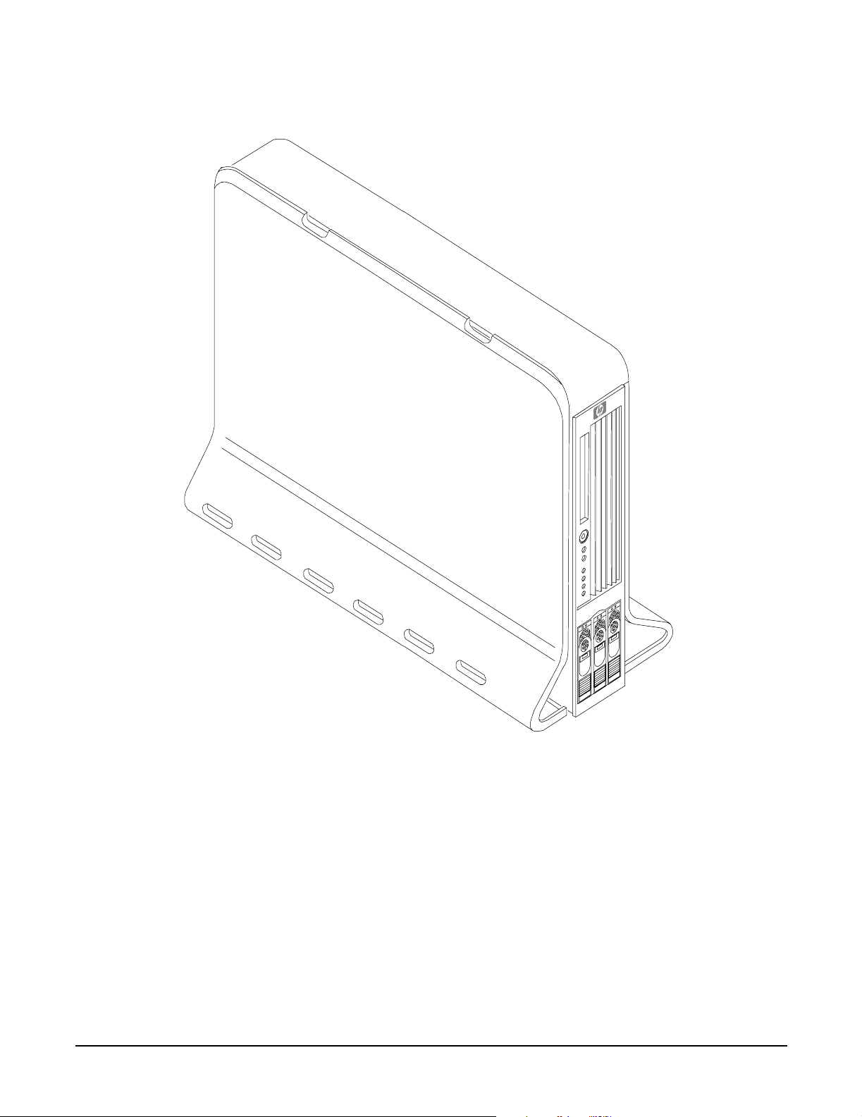
Figure 3-4 HP 9000 rp3410/rp3440 Server (Pedestal Mount)
Installing the System
Introduction
Chapter 3
57
Page 58

Installing the System
Introduction
Detailed Server Description
The following sections list the main subsystems within the HP 9000 rp3410 and rp3440 servers.
Fea t ures
Table 3-1 lists the features of the HP 9000 rp3410 and rp3440 servers.
Table 3-1 HP 9000 rp3410 and rp3440 Server Features
Features rp340 rp3440
PA-8800
Processors
PA-8900
Processors
Memory Supports up to 6 GB Supports up to 24 GB
HDDs Three 36 GB, 15K RPM Ultra320 SCSI
Video A6150B PCI card (optional) A6150B PCI card (optional)
SCSI N/A Integrated Ultra-3 SCSI dual-channel
LAN PCI Gigabit, fast Ethernet controller PCI Gigabit, fast Ethernet controller
PCI Slots Two 64 bit hot-pluggable PCI-X slots, 133
One or two processors at 800 MHz with
1.5 MB L1 cache/32 MB L2 cache
One or two processors at 800 MHz with
1.5 MB L1 cache/64 MB L2 cache
Hot Plug Disk or 3- 73 GB, 15K RPM
Ultra320 SCSI Hot Plug Disk or
Three 146 GB, 10K RPM Ultra320 SCSI
Hot Plug Disk
MHz, 3.3V slots
One to four processors at 800 MHz (or 1
GHz) and 1 GHz with 1.5 MB L1 cache/32
MB L2 cache
One to four processors at 800 MHz (or 1
GHz) and 1 GHz with 1.5 MB L1 cache/64
MB L2 cache
Three 36 GB, 15K RPM Ultra320 SCSI
Hot Plug Disk or 3- 73 GB, 15K RPM
Ultra320 SCSI Hot Plug Disk or
Three 146 GB, 10K RPM Ultra320 SCSI
Hot Plug Disk
controller; 80 MBs transfer rate with one
internal 68 pin connector and one external
68 pin connector.
Four 64 bit hot-pluggable PCI-X slots, 133
MHz, 3.3V slots
Core I/O Three serial ports, 4 USB 2.0 ports,
integrated RJ-45 LAN on iLO MP card.
DVD N/A IDE interface; 48x speed
External
Storage
Power Supply Redundant, (2N+1) 714 Watt Redundant, (2N+1) 714 Watt
Operating
Systems
58
Two-port U320 PCI-X RAID Smart Array
6402 (A9890A Controller)
HP-UX 11i v1, HP-UX 11i v2, and HP-UX
11i v3 (choice of Enterprise,
Mission-Critical, Technical Computing,
and Foundation operating environments)
Three serial ports, 4 USB 2.0 ports,
integrated RJ-45 LAN on iLO MP card.
Two-port U320 PCI-X RAID Smart Array
6402 (A9890A Controller)
HP-UX 11i v1, HP-UX 11i v2, and HP-UX
11i v3 (choice of Enterprise,
Mission-Critical, Technical Computing,
and Foundation operating environments)
Chapter 3
Page 59

Installing the System
Introduction
Firmware
Firmware consists of many individually linked binary images that are bound together by a single framework
at run time. Internally, the firmware employs a software database called a device tree to represent the
structure of the hardware platform and to provide a means of associating software elements with hardware
functionality.
The firmware incorporates Boot Console Handler (BCH) which provides an interface between the operating
system and the platform firmware.
The firmware supports the HP-UX 11i version 1 (and higher HP-UX versions that support PA-RISC systems)
operating system through the HP 9000 processor family standards and extensions, and has no operating
system-specific functionality included. The operating system is presented with the same interface to system
firmware, and all features are available to the operating system.
Event IDs for Errors and Events
The server firmware generates event IDs similar to chassis codes for errors, events, and forward progress to
the Integrity Integrated Light-Out Management Processor (iLO MP) through common shared memory. The
Integrity iLO MP interprets and stores event IDs. Reviewing these events helps you diagnose and
troubleshoot problems with the server.
Dimensions and Values
Table 3-2 lists the dimensions and their values of the HP 9000 rp3410 and rp3440 servers.
Table 3-2 Server Dimensions and Values
Dimensions Values
Rack dimensions (depth x width x height)
Pedestal dimensions (depth x width x height)
Rack weight
Pedestal weight
Pedestal footprint 2.1 sq ft (0.2 m2)
Rack units 2U
26.8 in (67.9 cm) max x 19.0 in (48.3 cm) x 3.4 in (8.6 cm)
26.6 in (67.5 cm) x 11.6 in (29.5 cm) x 19.5 in (49.4 cm)
Minimum: 38.6 lbs (17.5 kg)
Maximum: 49.0 lbs (22.2 kg)
Minimum: 49.4 lbs (22.4 kg)
Maximum: 56.3 lbs (25.5 kg)
Safety Information
Use care to prevent injury and equipment damage when performing removal and replacement procedures.
Voltages might be present within the server. Many assemblies are sensitive to damage by electrostatic
discharge.
Follow the safety conventions listed below to ensure safe handling of components, to prevent injury, and to
prevent damage to the server:
• When removing or installing any server component, follow the instructions provided in this guide.
• If installing a hot-swappable or hot-pluggable component when power is applied (fans are running),
reinstall the server cover immediately to prevent overheating.
Chapter 3
59
Page 60
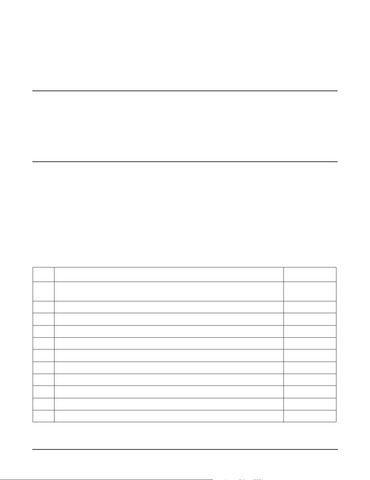
Installing the System
Introduction
• If installing a hot-pluggable component, complete the required software intervention before removing the
component.
• If installing an assembly that is neither hot-swappable, nor hot-pluggable, disconnect the power cable
from the external server power receptacle.
WARNING Ensure that the server is powered off and all power sources are disconnected from
the server before removing or installing server hardware unless you are removing or
installing a hot-swappable or hot-pluggable component.
Voltages are present at various locations within the server whenever a dc power
source is connected. This voltage is present even when the main power switch is
turned off.
Failure to observe this warning can result in personal injury or damage to
equipment.
• Do not wear loose clothing that can snag or catch on the server or on other items.
• Do not wear clothing subject to static charge build up, such as wool or synthetic materials.
• If installing an internal assembly, wear an antistatic wrist strap and use a grounding mat, such as those
included in the Electrically Conductive Field Service Grounding Kit (HP 9300-1609).
• Handle accessory boards and components by the edges only. Do not touch any metal-edge connectors or
any electrical components on accessory boards.
Installation Sequence and Checklist
Follow the steps in Table 3-3 sequentially to ensure successful installation of the server.
Table 3-3 Installation Sequence Checklist
Step Description Completed
1 Unpack and inspect the server shipping container; inventory the contents using
the packing slip.
2 Install additional components shipped with the server.
3 Install the server into a rack- or pedestal-mount.
4 Connect cables to the server.
4a Connect dc input power cable.
4b Connect LAN core I/O cable.
5 Set up the console.
6 Power on the server.
7 Access the console.
8 Boot the operating system.
9 Verify the server configuration.
60
Chapter 3
Page 61

Installing the System
Unpacking and Inspecting the Server
Unpacking and Inspecting the Server
This section describes procedures you perform before installation. Ensure that you have adequately prepared
your environment for the new server, received the components that you ordered, and verified that the server
and its containers are in good condition after shipment.
Verifying Site Preparation
Verifying site preparation is an essential factor of a successful server installation and includes the following
tasks.
Step 1. Gather LAN information and determine the two separate IP addresses for the iLO MP LAN and
the system LAN.
Step 2. Establish a method to connect to the server console.
Step 3. Verify electrical requirements and ensure that grounding specifications and power requirements
have been met.
Step 4. Validate server physical space requirements.
Step 5. Confirm environmental requirements.
Inspecting the Shipping Containers for Damage
HP shipping containers protect their contents under normal shipping conditions. After the equipment arrives,
carefully inspect each carton for signs of shipping damage. Shipping damage constitutes moderate to severe
damage, such as punctures in the corrugated carton, crushed boxes, or large dents. Normal wear or slight
damage to the carton is not considered shipping damage. If you find shipping damage to the carton, contact
your HP customer service representative immediately.
Unpacking the Server
To unpack a non-racked server, follow these steps.
NOTE HP recommends the use of a lifter, such as a RonI Company model 17000 SP 400 lifting device,
when moving a non-racked server.
Step 1. Use the instructions printed on the outside top flap of the carton; remove the banding and the outer
carton from the server pallet.
Step 2. Remove all inner accessory cartons and the top foam cushions, leaving only the server.
IMPORTANT Inspect each carton for shipping damage as you unpack the server.
Checking the Inventory
The sales order packing slip lists all of the equipment shipped from HP. Use this packing slip to verify that all
of the equipment has arrived.
Chapter 3
61
Page 62

Installing the System
Unpacking and Inspecting the Server
NOTE To identify each item by part number, see the sales order packing slip.
Returning Damaged Equipment
If the equipment is damaged, contact your HP customer service representative immediately. The service
representative initiates appropriate action through the transport carrier or the factory and assists you in
returning the equipment.
Unloading the Server with a Lifter
WARNING Use caution when using a lifter. Because of the weight of the server, you must center
the server on the lifter forks before lifting it off the pallet to avoid injury.
To unload the server from the pallet using a lifter, follow these steps:
Step 1. Unpack the server.
Step 2. Unroll the bottom corrugated tray corresponding to the side on which the lifter will be placed, and
slide the server as close to that edge of the pallet as possible.
Step 3. Break off any foam packaging which could prevent the lifter from being fully inserted under the
server. Do not remove the foam packaging from the corners of the server. This foam is required to
elevate the server and enable the forks of the lifter to be placed under the server.
Step 4. Insert the lifter forks under the server.
Step 5. Carefully roll the lifters forward until it is fully against the side of the server.
Step 6. Slowly raise the server off the pallet until it clears the pallet cushions.
Step 7. Carefully roll the lifter and server away from the pallet. Do not raise the server any higher than
necessary when moving it over to the rack.
62
Chapter 3
Page 63

Installing the System
Installing Additional Components
Installing Additional Components
This section describes how to install server components that are not installed before delivery.
Removing and Replacing Server Covers and Bezels
To upgrade, remove, or replace most server components, you must first remove the covers from the server
chassis. This section explains how to remove and replace the covers for both rack and pedestal-mounted
configurations.
WARNING Do not remove the server cover without first turning the server off and unplugging
the power cord from the outlet or power protection device unless you are only
replacing a hot-swappable fan. Always replace the cover before turning the server
on.
Rack-Mounted Server
To access the internal components on a rack-mounted server, pull the server out onto the rail guides and
remove the top cover.
Accessing a Rack-Mounted Server
HP 9000 rp3410 and rp3440 servers are designed to be rack mounted. The following procedure explains how
to gain access to a server that is mounted in an approved rack. For slide installation instructions, see the
Installation Guide, Mid-Weight Slide Kit (HP part number 5065-7291). This document can be accessed on the
Web at: http://www.hp.com/racksolutions.
WARNING Ensure that all anti-tip features (front and rear anti-tip feet installed; adequate
ballast properly placed; and so on) are employed before extending the server.
Extend the Server from the Rack
NOTE Ensure that there is enough area (approximately 1.5 meters {4.5 ft.}) to fully extend the server
out the front to work on it.
To extend the server from the rack, follow these steps:
NOTE If you are replacing a hot-swappable item, you can leave the server on and external cables
(including the power cord) connected.
Step 1. Power off the server and disconnect the power and external cables from the back of the server.
Step 2. Release the rack latches by rotating them outward.
Chapter 3
63
Page 64

Installing the System
Installing Additional Components
Figure 3-5 Release the Rack Latches
Step 3. Slide the server out of the rack until the guide-rail release clips are visible.
Insert the Server into the Rack
To insert the server into the rack, follow these steps:
Step 1. Press the rail clips on either side of the server inward and push the server into the rack until it
stops.
Step 2. Verify that the rack latches are closed.
Removing and Replacing the Top Cover on a Rack-Mounted Server
Removal of this cover is necessary when installing or removing many components.
Removing the Top Cover on a Rack-Mounted Server
NOTE If you are replacing a hot-swappable item, you can leave the server on and external cables
(including the power cord) connected.
Step 1. Power off the server and disconnect the power and external cables from the back of the server.
Step 2. Ensure the top cover lock keyswitch is in the unlocked position. Rotate the blue release lever
toward the back of the server and slide the cover toward the back of the server.
64
Chapter 3
Page 65
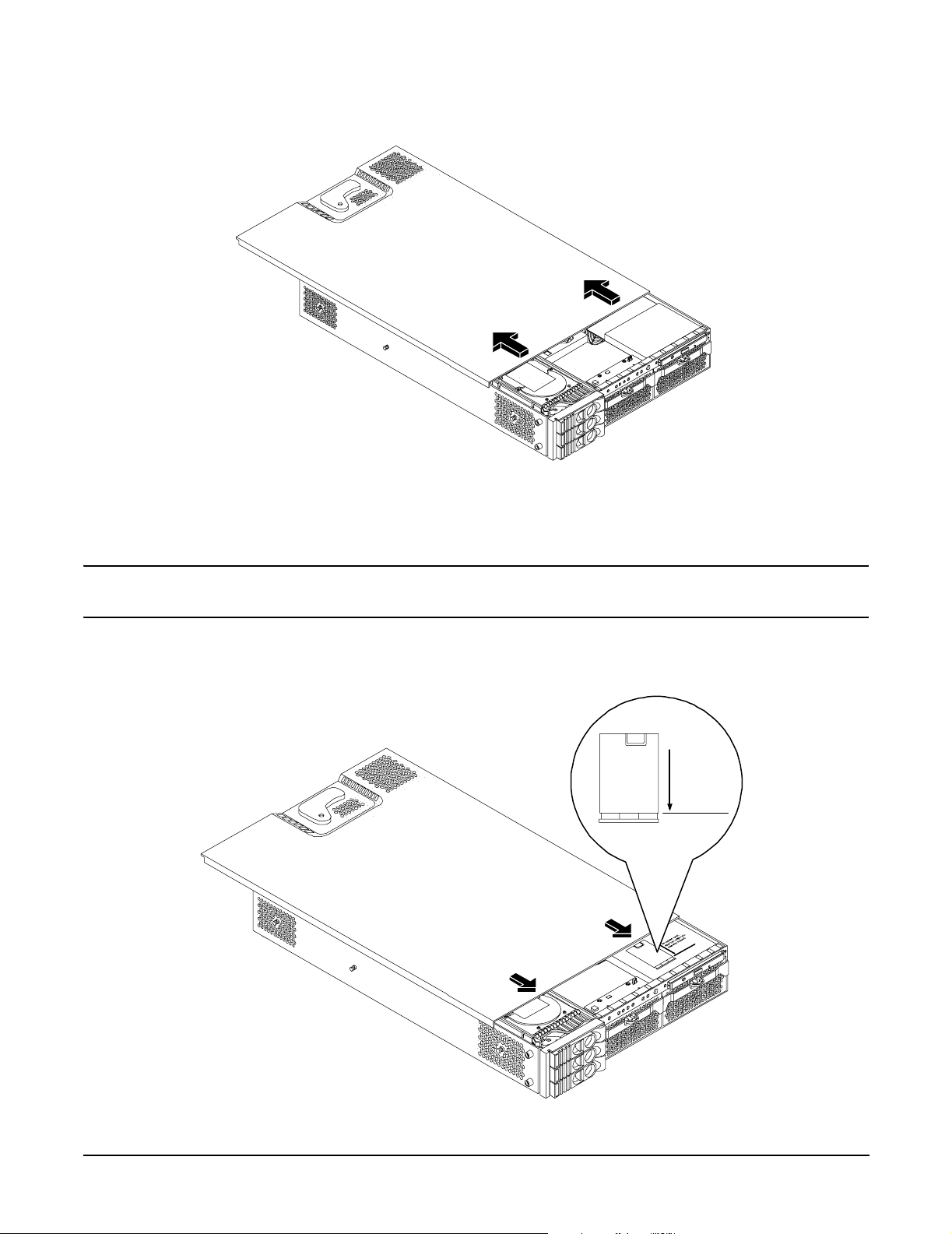
Figure 3-6 Removing and Replacing the Top Cover on a Rack-Mounted Server
Step 3. Lift the cover off the server chassis.
Installing the System
Installing Additional Components
Replacing the Top Cover on a Rack-Mounted Server
CAUTION Secure any wires or cables in the server so they will not get cut or interfere with the
replacement of the cover.
Step 1. Align the front edge of the cover with the alignment mark on the optical drive bay.
Figure 3-7 Aligning the Top Cover
To replace cover,
align front edge here
then slide forward
Chapter 3
65
Page 66

Installing the System
Installing Additional Components
Step 2. Grasp the blue release lever and slide the cover toward the front of the server until the lever snaps
into place.
Figure 3-8 Closing the Top Cover
Step 3. Slide the server into the rack enclosure and reconnect the power and external cables.
Removing and Replacing the Front Bezel on a Rack-Mounted Server
You must remove the front bezel from the chassis to gain access to the power supplies and optical drive.
Removing the Front Bezel on a Rack-Mounted Server
Step 1. Press in on the retaining clips located on the right-side of the front panel.
Figure 3-9 Front Bezel Retaining Clip
66
Chapter 3
Page 67

Installing Additional Components
Step 2. Rotate the front panel outward and lift it off the server chassis.
Replacing the Front Bezel on a Rack-Mounted Server
Step 1. Insert the bezel latches into the matching slots on the server chassis.
Step 2. Close the bezel and push toward the front of the server until it locks into place.
Figure 3-10 Replacing the Front Bezel
Installing the System
Accessing a Pedestal-Mounted Server
NOTE If you are replacing a hot-swappable item, you can leave the server on and external cables
(including the power cord) connected.
Removing the Side Cover on a Pedestal-Mounted Server
Step 1. Power off the server and disconnect the power and external cables.
Step 2. Remove the side cover.
a. Grasp both indentations at the top of the side panel and pull outward.
b. Lift the side cover off of the server chassis.
Chapter 3
67
Page 68
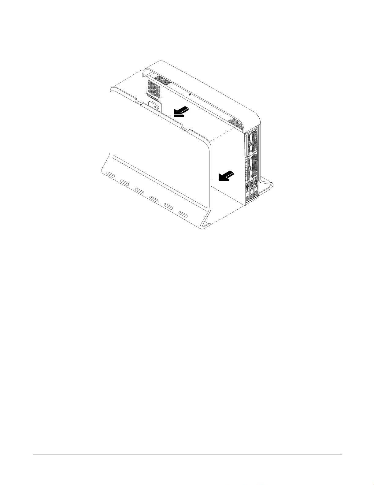
Installing the System
Installing Additional Components
Figure 3-11 Removing the Side Cover on a Pedestal-Mounted Server
Removing the Top Cover on Pedestal-Mounted Server
To remove the top cover, follow these steps:
Step 1. Turn the top cover lock keyswitch to the unlocked position.
Step 2. Rotate the blue release handle to release the latch.
Step 3. Slide the cover toward the back of the chassis and lift the cover off.
68
Chapter 3
Page 69
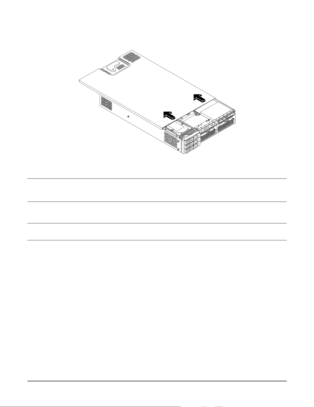
Figure 3-12 Removing the Top Cover on a Pedestal-Mounted Server
Step 4. Remove the top cover.
Installing the System
Installing Additional Components
CAUTION The server depends on the access panels being closed for proper cooling of internal
components. Operating the server with the cover removed can cause the server to
quickly overheat.
Replacing the Top Cover on a Pedestal-Mounted Server
CAUTION Secure any wires or cables in the server so they do not get cut or interfere with the replacement
of the cover.
To replace the top cover, follow these steps:
Step 1. Align the front edge of the top cover with the alignment mark on the optical drive bay.
Chapter 3
69
Page 70

Installing the System
Installing Additional Components
Figure 3-13 Top Cover Alignment Mark
To replace cover,
align front edge here
then slide forward
Step 2. Place the top cover on the chassis and slide it toward the front of the server until the blue release
lever snaps in place.
Figure 3-14 Replacing the Top Cover on a Pedestal-Mounted Server
Replacing the Side Cover on a Pedestal-Mounted Server
To replace the side cover, follow these steps:
Step 1. Align the cover’s mounting holes with the matching tabs on the server chassis.
70
Chapter 3
Page 71
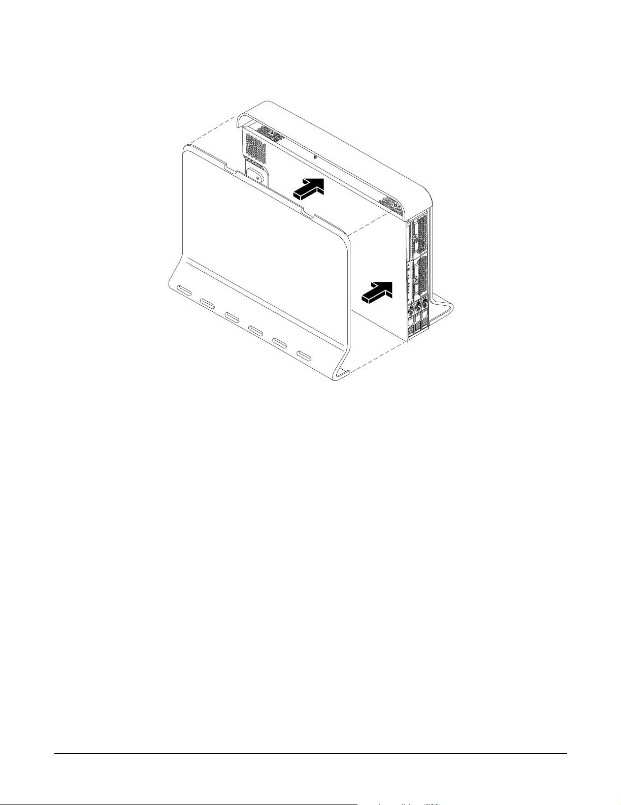
Installing Additional Components
Figure 3-15 Replacing the Side Cover on a Pedestal-Mounted Server
Installing the System
Step 2. Close the cover until it snaps onto the server chassis.
Removing and Replacing Front Bezel on a Pedestal-Mounted Server
You must remove the front bezel from the chassis to gain access to the power supplies and optical drive.
Removing the Front Bezel on a Pedestal-Mounted Server
To remove the front bezel parts, follow these steps:
Step 1. Use the indentation at the top edge of the bezel to pull the bezel away from the chassis and to a 45
degree angle.
Chapter 3
71
Page 72

Installing the System
Installing Additional Components
Figure 3-16 Removing the Front Bezel on a Pedestal-Mounted Server
Step 2. Lift the bezel off the mounting tabs and away from the chassis.
Replacing the Front Bezel on a Pedestal-Mounted Server
To replace the front bezel parts, follow these steps:
Step 1. Position the bezel at an approximate 45 degree angle and align the retaining slots at the bottom
with the retaining tabs on the chassis. Press the bezel against the chassis to engage the tabs.
72
Chapter 3
Page 73

Figure 3-17 Aligning the Pedestal Front Bezel
Installing the System
Installing Additional Components
Step 2. Rotate the bezel against the chassis so that it snaps into place.
Installing Internal Hard Disk Drives
This section provides information about installing additional internal hard disk drives.
CAUTION A hot-pluggable device can require interaction with the operating server before the device can
be safely installed into the server. Verify that the operating system supports installing disk
drives while the operating system is running. If the operating system does not support this
feature, shut down the operating system before attempting this procedure. Failure to observe
this caution will result in system failure.
Chapter 3
73
Page 74
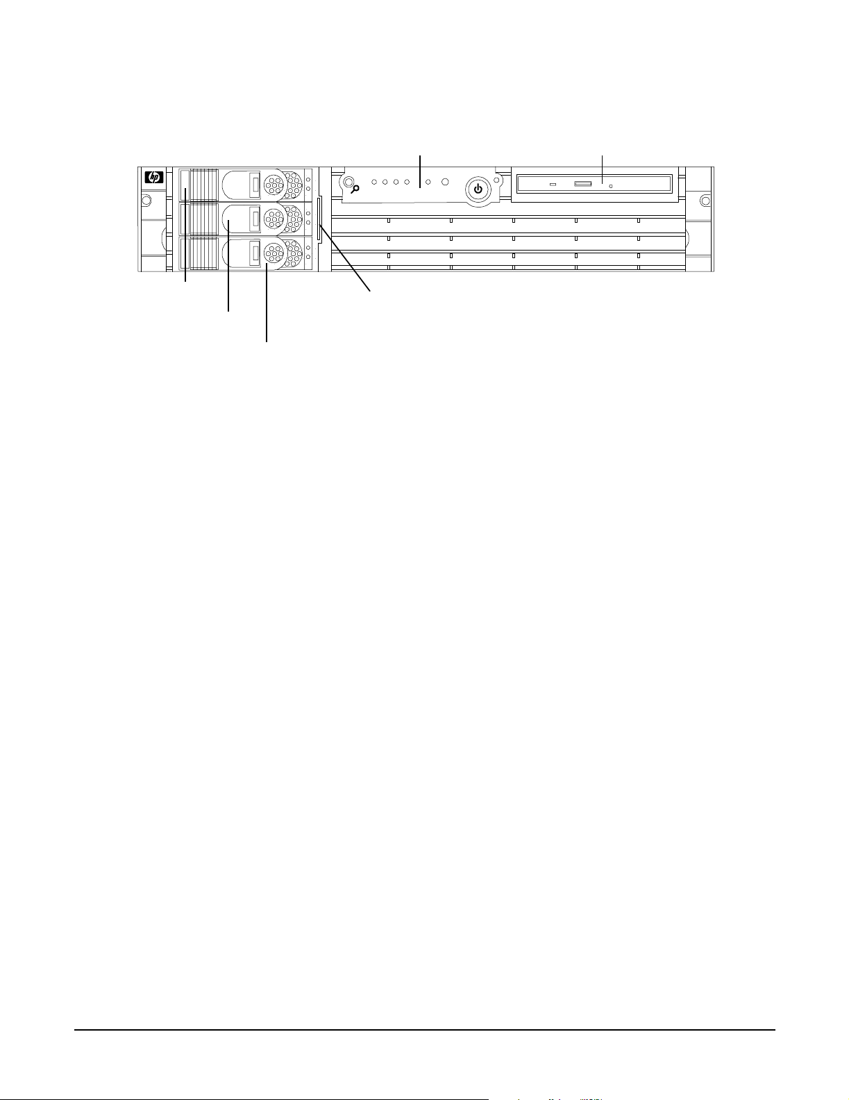
Installing the System
Installing Additional Components
Figure 3-18 Front View of the HP 9000 rp3410/rp3440 Server
Control Panel DVD Drive
LVD H D D 3
LVD HDD 2
LVD HDD 1
Two additional hard disk drives can be added to the server in slots 2 and 3. Always use low profile disk drives
(1 inch height) in HP 9000 rp3410 and rp3440 servers.
To install a hard disk drive, follow these steps:
Step 1. If you will be locking the hard drive in place, you must remove the cover to access the hard drive
lock. Proceed as follows:
a. If rack-mounted, slide the server out from the rack until it stops. (See “Extend the Server from
the Rack” on page 63.)
b. Remove the cover and bezel. (See “Removing and Replacing Server Covers and Bezels” on
page 63.)
Step 2. Remove the slot filler that is installed in the slot where the additional drive is to be installed.
System Product
Label (pull-out)
74
Chapter 3
Page 75
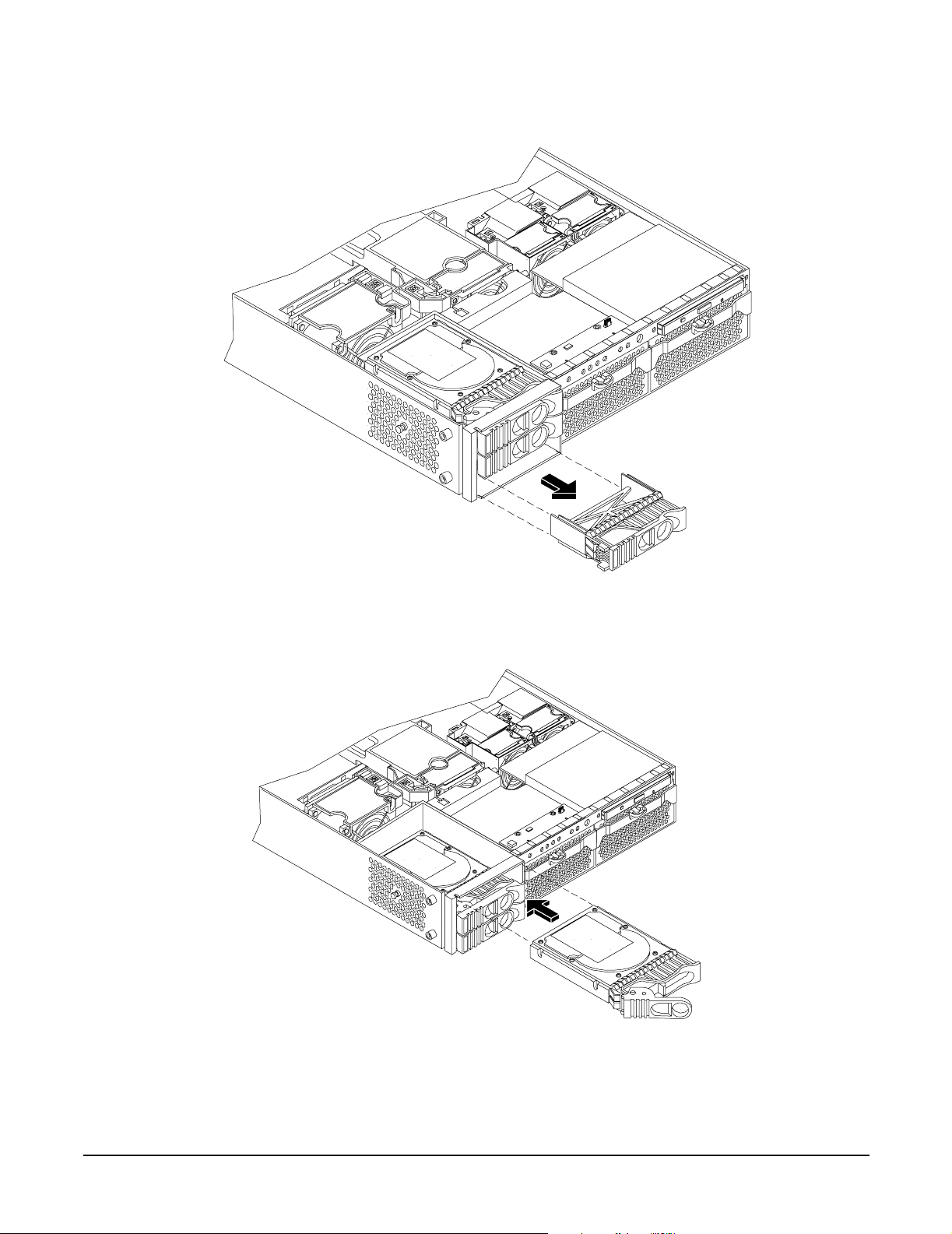
Figure 3-19 Filler Removal from Slot 1
Installing the System
Installing Additional Components
Step 3. Slide the hard disk drive into the slot until it is seated.
Figure 3-20 Disk Drive Installation in Slot 3
Step 4. Close the drive ejector handle by pushing it down until it clicks.
Step 5. If desired, lock the hard drive in place.
Chapter 3
75
Page 76

Installing the System
Installing Additional Components
a. Press the hard drive locking lever down into the locked position.
b. Replace the cover and bezel. (See “Removing and Replacing Server Covers and Bezels” on
page 63.)
Figure 3-21 Hard Drive Lock
Step 6. Verify the drive installation by using the system utilities.
• Use the iLO MP commands to verify operation.
• Use the BCH commands to verify operation.
• Use diagnostics provided by the offline diagnostic environment to exercise the module added.
Step 7. If rack-mounted, slide the server back into the rack until it stops.
Step 8. Check the installation of the hard disk drive by powering on the server and checking the virtual
front panel and System Event Log (SEL) for correct status for the hard disk drive.
76
Chapter 3
Page 77
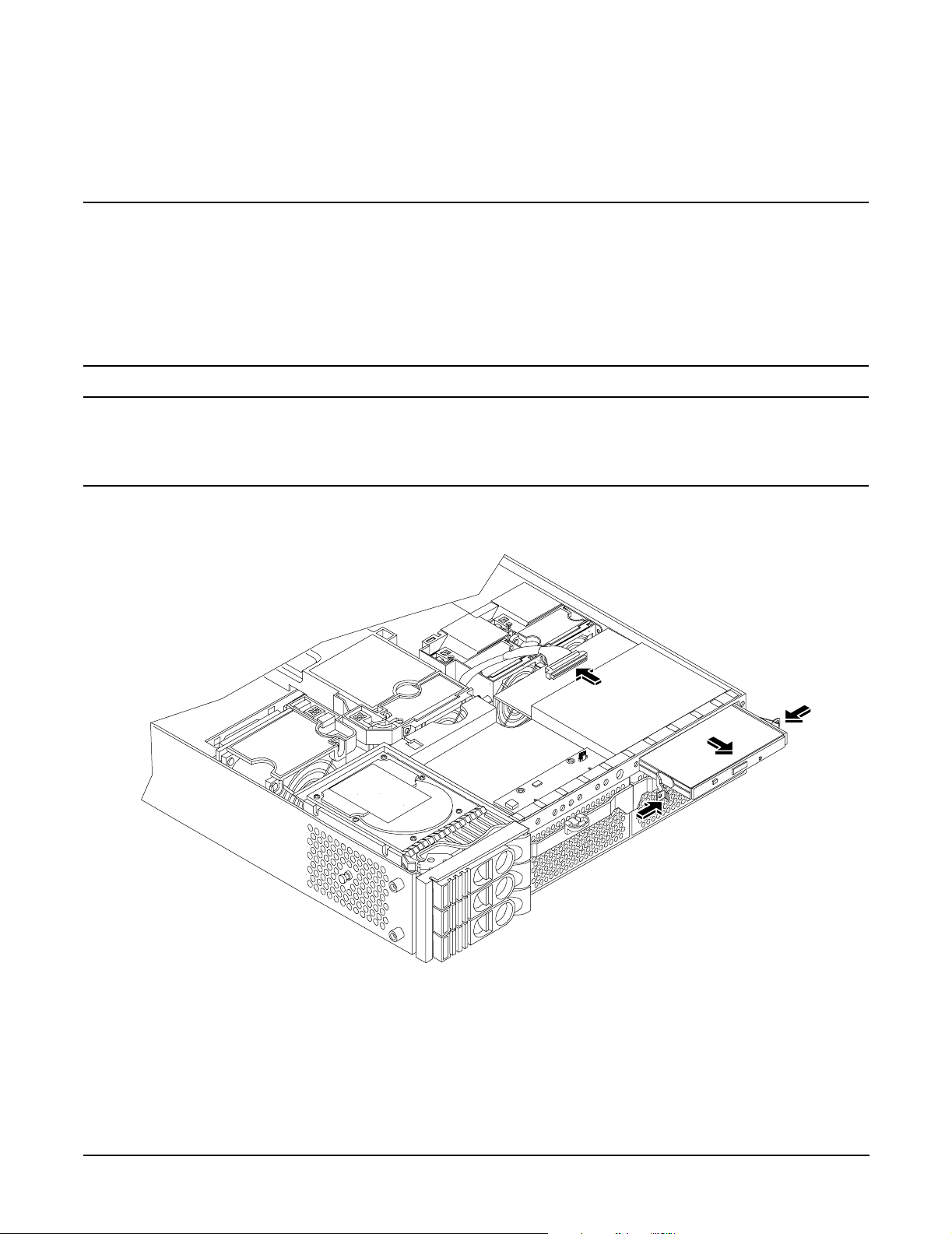
Installing the System
Installing Additional Components
Installing a DVD Drive
Install a DVD drive behind the front bezel.
WARNING Ensure that the server is powered off and all power sources have been disconnected
from the server before removing or replacing a removable media drive.
Voltages are present at various locations within the server whenever an ac power
source is connected. This voltage is present even when the main power switch is in
the off position.
Failure to observe this warning can result in personal injury or damage to
equipment.
CAUTION Observe all ESD safety precautions before attempting this procedure. Failure to follow ESD
safety precautions can result in damage to the server. Failure to properly complete the steps in
this procedure will result in erratic server behavior or system failure. For assistance with this
procedure contact your local HP Authorized Service Provider.
Figure 3-22 DVD Drive Installation
Chapter 3
77
Page 78

Installing the System
Installing Additional Components
Installing the DVD Drive
To install a DVD drive, follow these steps:
Step 1. Power off the server and disconnect power and external cables.
Step 2. Remove the front bezel and cover. (See “Removing and Replacing Server Covers and Bezels” on
page 63.)
Step 3. If a removable media drive has not previously been installed in the server, the drive slot will be
covered with a DVD drive filler. Remove the DVD drive filler.
Step 4. Slide the drive into the drive bay until it stops sliding and the retaining clips on both sides of the
drive snap into place (Figure 3-22).
Step 5. Connect the IDE cable on the back of the drive (Figure 3-22).
Step 6. Replace the cover and bezel. (See “Removing and Replacing Server Covers and Bezels” on page 63.)
Step 7. Reconnect the power and external cables and turn on the server.
Step 8. Verify the drive operation by using the system utilities.
• Use the iLO MP commands to verify operation.
• Use the BCH commands to verify operation.
• Use diagnostics provided by the offline diagnostic environment to exercise the newly installed
module.
Removing and Replacing Airflow Guides
You must remove airflow guides before installing processors or memory. The server has the following airflow
guides:
• The processor airflow guide ensures that the proper volume of air for cooling the dual processor module
power pods, processor modules, and voltage regulator modules flows over these components. You must
remove the processor airflow guide before removing or installing a dual processor module.
• The memory airflow guide ensures that the proper volume of air flows over the memory DIMMs to cool
them. You must remove the memory airflow guide to access memory DIMMs and sockets.
NOTE Air flows through the server from front to back.
78
Chapter 3
Page 79
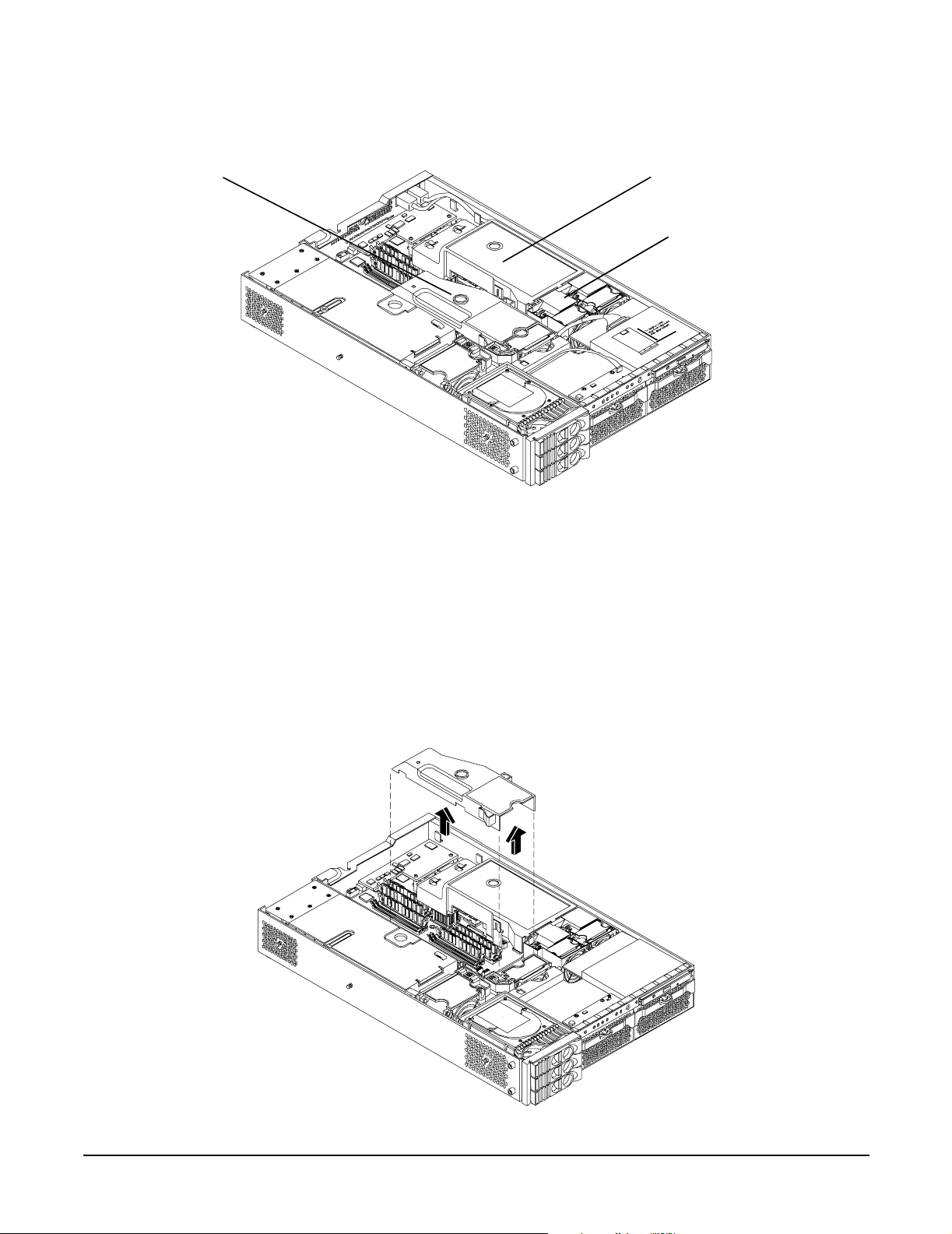
Figure 3-23 Airflow Guides Locations
Installing the System
Installing Additional Components
Memory Airflow Guide
Removing and Replacing the Memory Airflow Guide
Removing the Memory Airflow Guide
Step 1. Power off the server and disconnect power and external cables.
Processor Airflow Guide
Front Portion of Processor
Airflow Guide
Step 2. Remove the server chassis cover. (See “Removing and Replacing the Top Cover on a Rack-Mounted
Server” on page 64.)
Step 3. Grasp the memory airflow guide and lift it out of the server.
Figure 3-24 Removing the Memory Airflow Guide
Chapter 3
79
Page 80
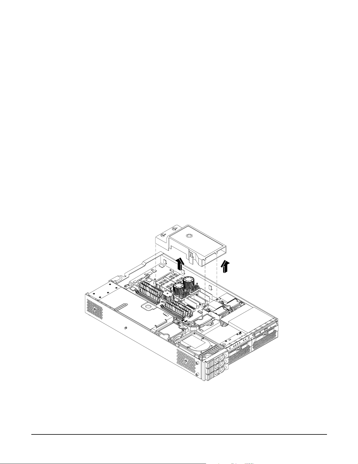
Installing the System
Installing Additional Components
Replacing the Memory Airflow Guide
Step 1. Align the guides on both sides of the airflow guide with the slots on the chassis.
Step 2. Insert the memory airflow guide in the slots.
Step 3. Replace the cover. (See “Removing and Replacing the Top Cover on a Rack-Mounted Server” on
page 64.)
Removing and Replacing the Processor Airflow Guide
Removing the Processor Airflow Guide
Step 1. Power off the server, disconnect power and external cables.
Step 2. Remove the server cover. (See “Removing and Replacing the Top Cover on a Rack-Mounted Server”
on page 64.)
Step 3. Remove the IDE cable and power module cables from the processor airflow guide cable clips.
Step 4. Remove the main portion of the airflow guide:
a. Hold the guide using the opening on top of the guide.
b. At the same time, grasp the back end of the processor airflow guide and lift the guide out of the
server.
Figure 3-25 Removing the Processor Airflow Guide
Step 5. Grasp system fan 1A and lift it from its socket.
80
Chapter 3
Page 81

Figure 3-26 Removing Fans 1A and 1B
Installing the System
Installing Additional Components
Fan 1A
Fan 1B
Step 6. Grasp system fan 1B and lift it from its socket (Figure 3-26).
Step 7. Remove the memory airflow guide. “Removing the Memory Airflow Guide” on page 79
Step 8. Rotate the clip clockwise to release the latch.
Chapter 3
81
Page 82

Installing the System
Installing Additional Components
Figure 3-27 Open the Release Clip
Step 9. Disconnect the power cable connected to the guide from the system board by squeezing the clips.
Step 10. Lift the front portion of the processor airflow guide out of the server.
Figure 3-28 Remove the Front Portion of the Processor Airflow Guide
82
Chapter 3
Page 83

Installing the System
Installing Additional Components
Replacing the Processor Airflow Guide
Step 1. Replace the front portion of the airflow guide:
a. Align the release latch of the front half of the airflow guide over the release latch post and snap
it in place.
b. Connect the power connector on the front portion of the guide to the connector on the system
board.
Step 2. Insert system fans 1A and 1B into their mounting positions.
Step 3. Route the processor turbo fan power cables through the processor heatsink posts so that the cables
will not be pinched between the heatsink posts and the processor airflow guide (Figure 3-29).
CAUTION Turbo fan power cables can be damaged if pinched between the heatsink posts and
the processor airflow guide. Ensure that the cables are below the top surface of the
heatsink posts before installing the processor airflow guide.
Figure 3-29 Routing the Turbofan Power Cables through Heatsink Posts
Step 4. Replace the main portion of the airflow guide:
a. Hold the opening on top of the processor airflow guide.
b. At the same time, grasp the back end of the airflow guide and insert the airflow guide into the
server.
c. Connect the power module cable.
d. Place the power and IDE cables in the cable clips.
e. Insert the two airflow guide retaining tabs into the two slots on the front half of the airflow
guide.
f. Replace the memory airflow guide. “Replacing the Memory Airflow Guide” on page 80
Step 5. Replace the server cover.
Chapter 3
83
Page 84

Installing the System
Installing Additional Components
Installing Additional System Memory
The server has 12 memory sockets for installing DDR SDRAM memory modules. System memory DIMMs are
located on the system board.
WARNING Ensure that the server is powered off and all power sources have been disconnected
from the server before removing or replacing system memory.
Voltages are present at various locations within the server whenever an ac power
source is connected. This voltage is present even when the main power switch is in
the off position.
Failure to observe this warning can result in personal injury or damage to
equipment.
CAUTION Observe all ESD safety precautions before attempting this procedure. Failure to follow ESD
safety precautions can result in damage to the server.
Supported DIMM Sizes
Supported DIMM sizes are as follows:
• 256 MB
• 512 MB
•1 GB
•2 GB)
• 4 GB (HP 9000 rp3440 only). If 4 GB DIMMs are used, only one configuration (8 X 4 GB in the first eight
sockets) is supported.
Dissimilar DIMM sizes can be used across the entire system board (except when 4 GB DIMMs are used) but
both DIMMs in a pair (first group of four, connectors 0A and 0B of HP 9000 rp3410) and all four DIMMs of
any quad must be identical.
84
Chapter 3
Page 85
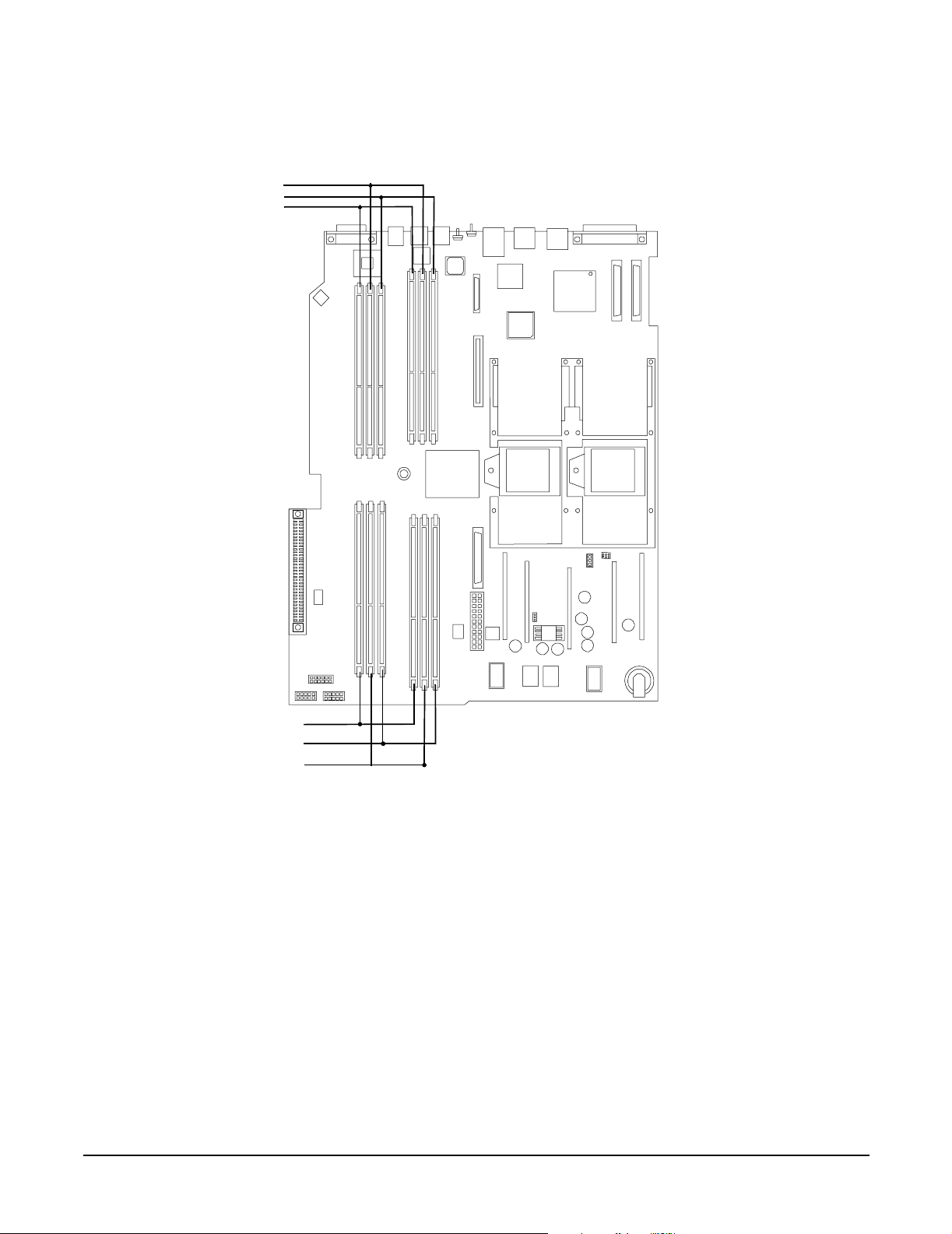
Figure 3-30 DIMM Slot Identification
Rear
Pair 6 (5A&5B)
Pair 4 (3A&3B)
Pair 2 (1A&1B)
Cell 1
Installing the System
Installing Additional Components
Cell 0
Pair 1 (0A&0B)
Pair 3 (2A &
Pair 5
Installing System Memory
1B
0B
5B
4B
1A
3B
2B
3A
5A
0
2A
4A
Quad 1 = Pair 1 & Pair 2
Quad 2 = Pair 3 & Pair 4
Quad 3 = Pair 5 & Pair 6
Front
When adding DIMMs, you must use a minimum of four like-sized DIMMs in the next available quad. If you
are installing DIMMs of different sizes, you must install the largest DIMMs (most memory) in the first quad.
DIMMs in the second quad can be equal to or smaller than (less memory) the DIMMs in the first quad. If you
install DIMMs in the third quad, they must be equal to or smaller than the DIMMs in the second quad.
rp3410 Memory Configuration T
The HP 9000 rp3410 server supports DDR SDRAM DIMMs with ECC and chip spare protection. This server
has 12 DIMM slots and supports a maximum of six GB of total system memory. Memory usage in the server
varies with the model designation.
Chapter 3
85
Page 86

Installing the System
Installing Additional Components
In the original server (model A7136A), memory can be installed as one or two pairs in the first quad (group of
four). This allows memory configurations of two, four, eight, or twelve DIMMs. In the current server (model
A7136B), memory must be installed as quads (groups of four). This allows memory configurations of four,
eight, or twelve DIMMs. Thus, the HP 9000 rp3410 server must include a minimum of 512 MB (model
A7136A) or 1 GB (model A7136B) and can include up to six GB of memory in combinations of 256 MB, 512
MB, and 1 GB DIMMs. Different size DIMMs can be installed in the server, but all four DIMMs in a quad
must be identical.
Memory Loading Rules and Performance Guidelines
• DIMMs must be installed in server load sequence (the first DIMM must be in the first slot, the second
DIMM must be in the second slot, and so on).
• A minimum of 512 MB (2 x 256 MB DIMMs in a model A7136A server) or 1 GB (4 x 256 MB DIMMs in a
model A7136B server) of memory must be installed in a HP 9000 rp3410 server.
• Maximum memory is 6 GB.
• A minimum of two DIMMs (one pair) is required in the model A7136A server.
• A minimum of four DIMMs (one quad) is required in the model A7136B server.
• All DIMMs within a quad must be identical.
• Memory can be ordered in amounts of 1 GB (4 x 256 MB), 2 GB (4 x 512 MB), 4 GB (4 x 1 GB), 8 GB (4 x 2
GB), and 16 GB (4 x 4 GB).
• Memory is loaded across both memory busses (two DIMMs on each bus) to ensure maximum bandwidth
and performance.
• Total memory bandwidth is 8.5 GB/s, split across two 4.25 GB/s memory buses.
• Open page memory latency is 80 nanoseconds.
rp3440 Memory Configuration
The HP 9000 rp3440 supports DDR SDRAM DIMMs with ECC and chip spare protection. This server has 12
DIMM slots, but maximum system memory is 32 GB due to cooling limitations. Memory must be installed as
quads (groups of four). This allows memory configurations of four, eight, or twelve DIMMs. Thus, the HP 9000
rp3440 server must include a minimum of 1 GB and can include up to 24 GB of memory in combinations of
256 MB, 512 MB, 1 GB, and 2 GB DIMMs, or 32 GB of memory consisting of eight 4 GB DIMMs. Different size
DIMMs can be installed in the server (except when 4 GB DIMMs are used), but all four DIMMs in a quad
must be identical.
Memory Loading Rules and Performance Guidelines
• Minimum memory is 1 GB (4 x 256 MB).
• Maximum memory is 32 GB (8 x 4 GB installed in the first eight slots—the remaining slots must remain
empty if 4 GB DIMMs are installed).
• Memory DIMMs must be installed in groups of four (quads).
• All DIMMs within a quad must be identical.
• Memory must be loaded in the specific order outlined on the system board.
• Memory can be ordered in amounts of 512 MB (2 x 256 MB), 1 GB (4 x 256 MB), 2 GB (4 x 512 MB), 4 GB
(4 x 1 GB), 8 GB (4 x 2 GB), and 16 GB (4 x 4 GB).
• Each quad of memory is loaded across both memory buses (two DIMMs on each bus) to ensure maximum
bandwidth and performance.
86
Chapter 3
Page 87

Installing the System
Installing Additional Components
• Total memory bandwidth is 8.5 GB/s, split across two 4.25 GB/s memory buses.
• Open page memory latency is 80 nanoseconds.
The memory subsystem supports chip-spare functionality. Chip spare enables an entire SDRAM chip on a
DIMM to be bypassed (logically replaced) in the event that a multi-bit error is detected on that SDRAM.
In order to use the chip spare functionality, only DIMMs built with x4 SDRAM parts can be used, and these
DIMMs must be loaded in quads (two DIMMs per memory cell, loaded in the same location in each memory
cell).
System Firmware Requirements
If you are using 4 GB DIMMs in a HP 9000 rp3440 server, system firmware must be greater than revision
44.24. Use the BCH FV command, or the iLO MP SR command to display the system firmware revision status.
If necessary, use the iLO MP SR command to upgrade system firmware. (Detailed instructions are downloaded
with the upgrade.)
Installation Procedure
To install DIMMs, follow these steps:
Step 1. Power off the server and disconnect all power and external cables.
Step 2. Remove the server cover. (See “Removing and Replacing Server Covers and Bezels” on page 63.)
Step 3. Remove the memory airflow guide. (See “Removing the Memory Airflow Guide” on page 79.)
CAUTION To ensure that memory modules are not damaged during removal or installation,
power off the server and unplug the power cord from the ac power outlet. Wait until
the LED on the back of the power supply turns off before removing or installing
memory.
Step 4. Locate the slot into which the DIMM will be installed. Holding the memory module by its left and
right edges, insert the module into the socket (Figure 3-31.)
NOTE The memory modules are keyed and can only be inserted in one direction. When the
module is correctly seated, the retainer clips will return to their fully upright
position. Snap the clips firmly into place to ensure that the DIMMs are seated
properly.
Step 5. Evenly push down firmly on each end of the DIMM until it seats in the socket. Ensure the
extraction levers are in the closed position.
Chapter 3
87
Page 88

Installing the System
Installing Additional Components
Figure 3-31 Inserting DIMM into Connector
Step 6. Replace the memory airflow guide. (See “Replacing the Memory Airflow Guide” on page 80.)
Step 7. Replace the server cover. (See “Removing and Replacing the Top Cover on a Rack-Mounted Server”
on page 64.)
Step 8. Reconnect all power and external cables and turn on the server.
Step 9. Verify the memory installation by using the system utilities.
• Use the iLO MP commands to verify operation.
• Use the BCH commands to verify operation.
• Use diagnostics provided by the offline diagnostic environment (ODE) to exercise the memory
added.
Removing and Replacing the PCI Card Cage
Accessory cards are installed in a removable PCI card cage. This section explains how to remove and replace
the PCI card cage. Removal is required to install accessory cards.
Removing the PCI Card Cage
To remove the PCI card cage from the server, follow these steps:
Step 1. Remove the cover. (See “Removing and Replacing the Top Cover on a Rack-Mounted Server” on
page 64.)
Step 2. Disconnect the cables from the PCI cards.
88
Chapter 3
Page 89

Installing the System
Installing Additional Components
Step 3. Lift up on the PCI card cage release lever and the back edge of the PCI card cage and lift the PCI
card cage out of the server.
Figure 3-32 Removing the PCI Card Cage
Step 4. Grasp the PCI card cage cover and slide it away from the bulkhead end of the cage, then lift the
cover off.
Chapter 3
89
Page 90
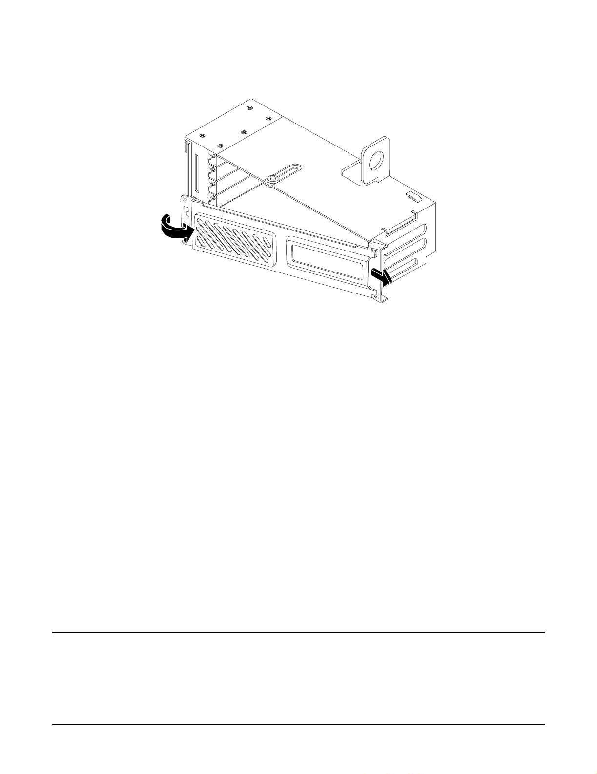
Installing the System
Installing Additional Components
Figure 3-33 Removing the PCI Card Cage Cover
Step 5. Unscrew the bulkhead screw that holds the accessory card holder (if installed) in place.
Step 6. The PCI slots are now accessible for installation of additional cards.
Replacing the PCI Card Cage
To replace the PCI card cage, follow these steps:
Step 1. Hold the PCI card cage cover in mounting position and slide it toward the bulkhead end of the cage.
Step 2. Hold the PCI card cage above the chassis mounting position, such that the bulkhead end of the cage
is toward the rear of the server. (Figure 3-32.)
Step 3. Hold the PCI card cage release lever in the raised position and lower the card cage into the server
chassis.
Step 4. Press the PCI card cage release lever into the lowered position to lock the card cage into the server
chassis.
Installing PCI Cards
The server can contain up to 4 PCI cards. PCI cards are located in the PCI card cage. The HP 9000 rp3410
server provides two 64-bit, 133 MHz PCI-X card sockets as slots 1 and 2. The HP 9000 rp3440 server provides
four 64-bit, 133 MHz PCI-X card sockets as slots 1 through 4.
HP 9000 rp3410 and rp3440 servers have the following accessory card sockets:
• Four 64-bit, 133 MHz PCI-X card sockets.
WARNING Ensure that the server is powered off and all power sources have been disconnected
from the server before removing or replacing a PCI card.
Voltages are present at various locations within the server whenever an ac power
source is connected. This voltage is present even when the main power switch is in
the off position.
90
Chapter 3
Page 91

Installing the System
Installing Additional Components
Failure to observe this warning can result in personal injury or damage to
equipment.
CAUTION Observe all ESD safety precautions before attempting this procedure. Failure to follow ESD
safety precautions can result in damage to the server.
Carefully read the following information concerning PCI slot configuration. Inserting a PCI card into a slot
that is not configured to accept it can cause operation failure or the PCI card to operate at less than optimum
speed. PCI slots are numbered 1 (top of card cage) through 4 (bottom of card cage). See the labels on the rear
panel of the chassis for correct PCI slot number identification.
Installing a PCI Card
Step 1. Remove the cover. (See “Removing and Replacing the Top Cover on a Rack-Mounted Server” on
page 64.)
Step 2. Remove the PCI cage. (See “Removing the PCI Card Cage” on page 88.)
Step 3. Grasp the edges of the PCI card to be installed and evenly press the card into the PCI backplane
connector.
Figure 3-34 Installing a PCI Card
Step 4. Connect any internal cables that are required by the PCI card.
Step 5. Install the accessory card holder and secure in place by tightening the associated bulkhead screws.
Step 6. Reinstall the PCI cage. (See “Replacing the PCI Card Cage” on page 90.)
Step 7. Replace the cover. (See “Removing and Replacing the Top Cover on a Rack-Mounted Server” on
page 64.)
Step 8. Verify the PCI card installation by using the system utilities.
Chapter 3
91
Page 92

Installing the System
Installing Additional Components
• Use the iLO MP commands to verify operation.
• Use the BCH commands to verify operation.
• Use diagnostics provided by the offline diagnostic environment to exercise the card added.
Installing an Additional Power Supply
The supported configuration of the HP 9000 rp3410 and rp3440 servers requires a minimum of one power
supply to be installed. A second, optional hot-swappable power supply, can be installed to provide redundant
(N+1) capability.
The power supplies in the server are hot-swappable; that is, if one power supply stops working or exhibits
voltage problems, the remaining supply can support the server until the failed unit is replaced. A power
supply can be removed and replaced without turning off the server on servers with two power supplies.
CAUTION Before removing a power supply, make sure the second power supply functions properly. The
two green LEDs inside the supply must both be lit on the second supply before the failed power
supply can be safely removed.
To replace the power supply, follow these steps:
Step 1. Remove the front bezel from the server (See “Removing and Replacing Front Bezel on a
Pedestal-Mounted Server” on page 71.)
Step 2. Remove the power supply filler panel.
Figure 3-35 Removing the Power Supply Filler Panel
Power Supply 1
Step 3. Open the power supply release lever and slide the power supply into place.
92
Chapter 3
Page 93
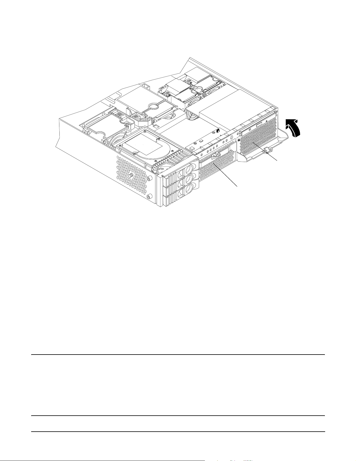
Figure 3-36 Replacing the Power Supply
Installing the System
Installing Additional Components
Power Supply
Power Supply 1
Step 4. Push in on the power supply release lever to lock the retaining clip in place.
Step 5. Replace the front bezel. (See “Removing and Replacing Front Bezel on a Pedestal-Mounted Server”
on page 71.)
Step 6. Verify that both power supply LEDs are lit.
Step 7. Use the iLO MP PS command to verify power supply operation.
Installing an Additional Processor Module
This section provides information about installing dual processor modules. The modules are located on the
system board which is accessible by removing the server cover.
The HP 9000 rp3410 server supports one processor socket. This socket will accept one dual processor module
which contains two 800 MHz CPUs. The HP 9000 rp3410 server 1P/1C configuration includes two CPUs in a
single module, but only one CPU is enabled. (The second CPU can be enabled as part of a server upgrade.)
The HP 9000 rp3440 server supports two processor sockets. Each socket will accept one dual processor
module which contains either two 800 MHz CPUs or two 1 GHz CPUs.
WARNING Ensure that the server is powered off and all power sources have been disconnected
from the server before removing or replacing a dual processor module.
Voltages are present at various locations within the server whenever an ac power
source is connected. This voltage is present even when the main power switch is in
the off position.
Failure to observe this warning can result in personal injury or damage to
equipment.
Chapter 3
93
Page 94

Installing the System
Installing Additional Components
CAUTION Failure to properly complete the steps in this procedure will result in erratic server behavior or
system failure. For assistance with this procedure contact your local HP Authorized Service
Provider.
Observe all ESD safety precautions before attempting this procedure. Failure to follow ESD
safety precautions can result in damage to the server.
NOTE Processor tool kit (HP part number 5069-5441) is required for installation of a processor
module.
Processor modules are located on the system board. The system board can support either one or two dual
processor modules. The CPU0 socket is located at the right of the system board and the CPU1 socket is
located at the left of the system board next to the bridge assembly. In a 1P/1C, 1P/2C server, the single dual
processor module must be installed in the CPU0 socket.
Install a second dual processor module as follows:
Step 1. Power off the server and disconnect all power and external cables.
Step 2. Remove the cover. (See “Removing and Replacing Server Covers and Bezels” on page 63.)
Step 3. Remove the memory airflow guide. (See “Replacing the Memory Airflow Guide” on page 80.)
Step 4. Remove the processor airflow guide. (See “Removing the Processor Airflow Guide” on page 80.)
Step 5. Unlock the dual processor module locking mechanism using the CPU install tool (2.5 mm driver or
Allen Wrench). Insert the tool into the hole that runs down through the edge of the heatsink and
rotate the special processor tool 180 degrees counterclockwise. Verify that the dual processor
module socket locking mechanism is rotated into the unlocked position.
Figure 3-37 Unlocking the Dual Processor Module Locking Mechanism
CPU Install Tool
(2.5 mm Driver or
Allen Wrench)
Step 6. Remove any protective packaging from the processor module.
94
Chapter 3
Page 95
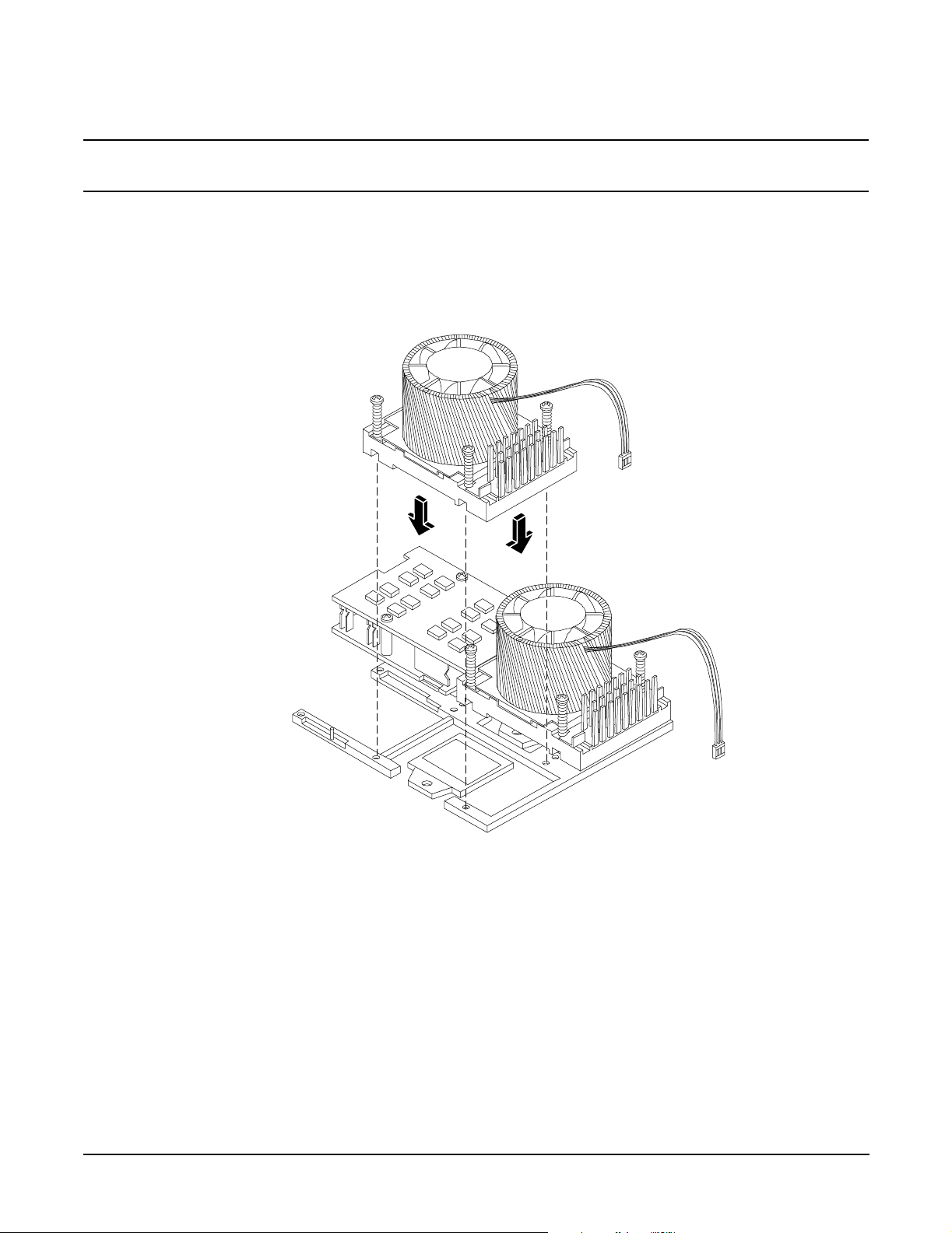
Installing the System
Installing Additional Components
NOTE Protective covers can be installed to protect connector pins. These covers can be
saved for future use.
Step 7. Use the four locator posts on the heatsink and the turbo fan power cable to properly align the fan
and dual processor module on the system board. The four locator posts will fit in locator holes on
the system board processor module mount. The turbo fan power cable must be positioned so that it
is located on the side of the heatsink that faces the front of the server.
Figure 3-38 Aligning the Processor Module
Step 8. Use the special CPU install tool (2.5 mm driver or Allen Wrench) to lock the dual processor module
in place on the system board. To do this, insert the CPU install tool into the hole that runs down the
side of the heatsink and rotate it clockwise 180 degrees.
Chapter 3
95
Page 96

Installing the System
Installing Additional Components
Figure 3-39 Locking the Dual Processor Module in Place
CPU Install Tool
(2.5 mm Driver or Allen
Wrench)
Step 9. Slide the sequencing retainer plate toward the front of the server.
Figure 3-40 Slide the Sequencing Retainer Plate
Step 10. Screw in the four heatsink captive screws in a criss-cross torquing pattern by alternately
tightening the screws so as not to completely tighten one screw before the others.
96
Chapter 3
Page 97
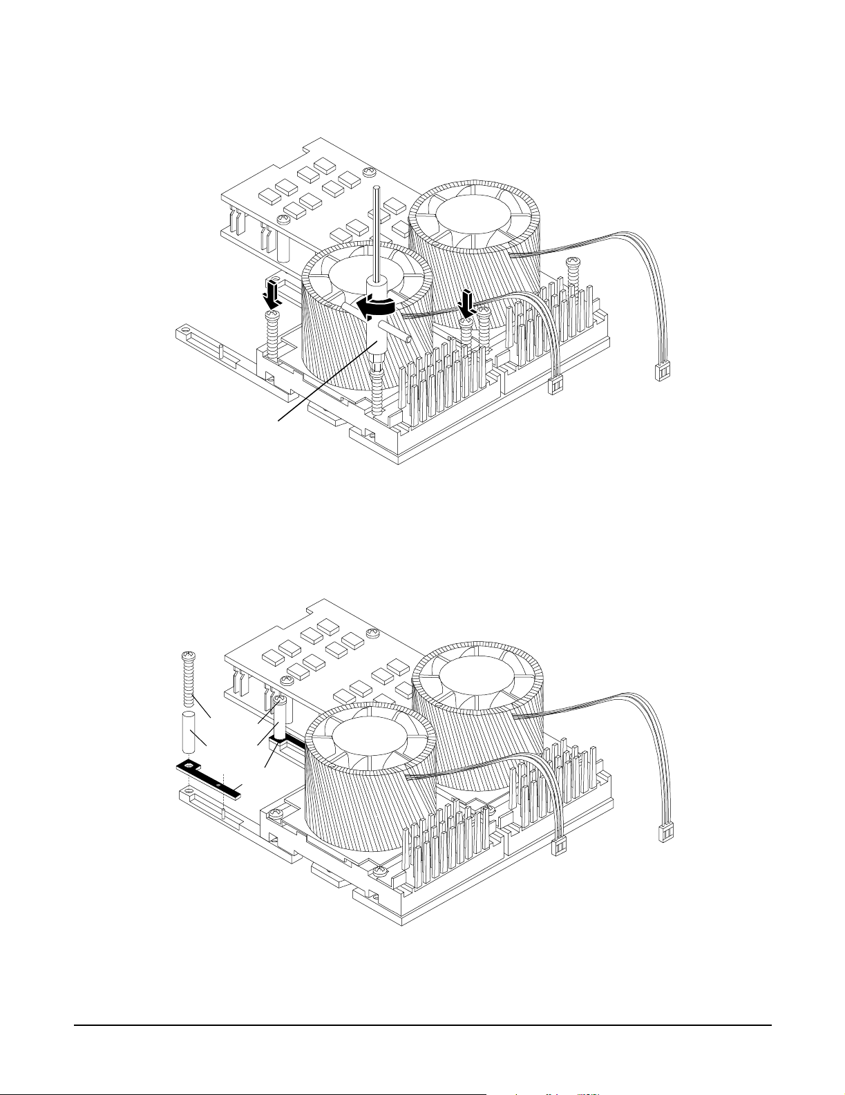
Figure 3-41 Secure the Captive Screws
CPU Install Tool
Installing the System
Installing Additional Components
Step 11. Locate the two power pod module shims on the system board. (On servers delivered with only one
dual processor module installed, the power module shims are held in place by screws with plastic
spacers over the threads.) Remove the holding screws and discard the plastic spacers. Retain the
screws for use when installing the power module.
Figure 3-42 Power Module Shims
Screws
Spacers
Shims
Step 12. Slide the power pod module on the system board’s metal mounting bracket so that the power pod
module connector connects with its connector on the processor module.
Chapter 3
97
Page 98

Installing the System
Installing Additional Components
Figure 3-43 Aligning the Processor Module Power Pod
Step 13. Align the two mounting screw holes on the power pod module with the screw holes in the shims on
the system board’s metal mounting bracket. Screw in the power pod module mounting screws. (Use
the screws removed in step 11.)
98
Chapter 3
Page 99

Installing the System
Installing Additional Components
Figure 3-44 Installing the Processor Module Power Pod Mounting Screws
Step 14. Connect the power pod cable to the power connector on the system board.
Chapter 3
99
Page 100

Installing the System
Installing Additional Components
Figure 3-45 Connecting the Power Pod Cable
100
Chapter 3
 Loading...