

Page 1

User's Manual
HP 9000 Model A-180
Manufacturing Part Number : Z4045-90002
February 2000
Page 2

Notice
Hewlett-Packard makes no warranty of any kind with regard to this material, including but not
limited to, the implied warranties of merchantability and fitness for a particular purpose.
Hewlett-Packard shall not be liable for errors contained herein or for incidental or consequential damages in
connection with the furnishing, performance, or use of this material.
Hewlett-Packard assumes no responsibility for the use or reliability of its software on equipment that is not
furnished by Hewlett-Packard.
All rights are reserved. No part of this document may be photographed, reproduced, or translated to another
language without prior written consent of Hewlett-Packard Company.
The information contained in this document is subject to change without notice.
Revision History
First Edition Initial Release.
2
Page 3

3
Page 4

4
Page 5

1. A-Class System Overview and Reference
A-Class Server - System Overview . . . . . . . . . . . . . . . . . . . . . . . . . . . . . . . . . . . . . . . . . . . . . . . . . . . . . . 10
System Hardware Overview. . . . . . . . . . . . . . . . . . . . . . . . . . . . . . . . . . . . . . . . . . . . . . . . . . . . . . . . . . 10
System Software Overview. . . . . . . . . . . . . . . . . . . . . . . . . . . . . . . . . . . . . . . . . . . . . . . . . . . . . . . . . . . 10
A-Class Server Service Reference Information . . . . . . . . . . . . . . . . . . . . . . . . . . . . . . . . . . . . . . . . . . . 11
Overview . . . . . . . . . . . . . . . . . . . . . . . . . . . . . . . . . . . . . . . . . . . . . . . . . . . . . . . . . . . . . . . . . . . . . . . . . 11
A-Class Server System Block Diagram . . . . . . . . . . . . . . . . . . . . . . . . . . . . . . . . . . . . . . . . . . . . . . . . . . 12
Overview . . . . . . . . . . . . . . . . . . . . . . . . . . . . . . . . . . . . . . . . . . . . . . . . . . . . . . . . . . . . . . . . . . . . . . . . . 12
A-Class Server System Regulatory Compliance Statements . . . . . . . . . . . . . . . . . . . . . . . . . . . . . . . . . 13
Overview . . . . . . . . . . . . . . . . . . . . . . . . . . . . . . . . . . . . . . . . . . . . . . . . . . . . . . . . . . . . . . . . . . . . . . . . . 13
Regulatory Information . . . . . . . . . . . . . . . . . . . . . . . . . . . . . . . . . . . . . . . . . . . . . . . . . . . . . . . . . . . . . 14
Safety . . . . . . . . . . . . . . . . . . . . . . . . . . . . . . . . . . . . . . . . . . . . . . . . . . . . . . . . . . . . . . . . . . . . . . . . . . . 14
Battery Notice . . . . . . . . . . . . . . . . . . . . . . . . . . . . . . . . . . . . . . . . . . . . . . . . . . . . . . . . . . . . . . . . . . . . . 14
Declaration of Conformity . . . . . . . . . . . . . . . . . . . . . . . . . . . . . . . . . . . . . . . . . . . . . . . . . . . . . . . . . . . 15
2. A-Class Server Installation
A-Class Server System Installation . . . . . . . . . . . . . . . . . . . . . . . . . . . . . . . . . . . . . . . . . . . . . . . . . . . . . 22
Overview . . . . . . . . . . . . . . . . . . . . . . . . . . . . . . . . . . . . . . . . . . . . . . . . . . . . . . . . . . . . . . . . . . . . . . . . . 22
A-Class Server Site Preparation . . . . . . . . . . . . . . . . . . . . . . . . . . . . . . . . . . . . . . . . . . . . . . . . . . . . . . . 23
Overview . . . . . . . . . . . . . . . . . . . . . . . . . . . . . . . . . . . . . . . . . . . . . . . . . . . . . . . . . . . . . . . . . . . . . . . . . 23
Space Requirements . . . . . . . . . . . . . . . . . . . . . . . . . . . . . . . . . . . . . . . . . . . . . . . . . . . . . . . . . . . . . . . . 23
Input Power Requirements . . . . . . . . . . . . . . . . . . . . . . . . . . . . . . . . . . . . . . . . . . . . . . . . . . . . . . . . . . 25
Cooling Requirements . . . . . . . . . . . . . . . . . . . . . . . . . . . . . . . . . . . . . . . . . . . . . . . . . . . . . . . . . . . . . . 26
Stand-Alone A-Class Server Unpack and Install Instructions . . . . . . . . . . . . . . . . . . . . . . . . . . . . . . . . 27
Overview . . . . . . . . . . . . . . . . . . . . . . . . . . . . . . . . . . . . . . . . . . . . . . . . . . . . . . . . . . . . . . . . . . . . . . . . . 27
Open and Unload the Carton . . . . . . . . . . . . . . . . . . . . . . . . . . . . . . . . . . . . . . . . . . . . . . . . . . . . . . . . . 27
Unpack the Server . . . . . . . . . . . . . . . . . . . . . . . . . . . . . . . . . . . . . . . . . . . . . . . . . . . . . . . . . . . . . . . . . 28
Open the Accessory Kit. . . . . . . . . . . . . . . . . . . . . . . . . . . . . . . . . . . . . . . . . . . . . . . . . . . . . . . . . . . . . . 28
Open the Installation Instructions and Regulatory Information Packet . . . . . . . . . . . . . . . . . . . . . . 28
Installing a Stand-alone System . . . . . . . . . . . . . . . . . . . . . . . . . . . . . . . . . . . . . . . . . . . . . . . . . . . . . . 28
Cabinet-Mounted A-Class Server System Unpack and Install . . . . . . . . . . . . . . . . . . . . . . . . . . . . . . . 29
Overview . . . . . . . . . . . . . . . . . . . . . . . . . . . . . . . . . . . . . . . . . . . . . . . . . . . . . . . . . . . . . . . . . . . . . . . . . 29
Installing a Factory-integrated Cabinet . . . . . . . . . . . . . . . . . . . . . . . . . . . . . . . . . . . . . . . . . . . . . . . . 29
Installing a Stand-alone System in an HP-supported Cabinet . . . . . . . . . . . . . . . . . . . . . . . . . . . . . . 35
External Connections . . . . . . . . . . . . . . . . . . . . . . . . . . . . . . . . . . . . . . . . . . . . . . . . . . . . . . . . . . . . . . . 38
Installing Internal Add-On Components . . . . . . . . . . . . . . . . . . . . . . . . . . . . . . . . . . . . . . . . . . . . . . . . . 41
Installing Memory (RAM) Modules. . . . . . . . . . . . . . . . . . . . . . . . . . . . . . . . . . . . . . . . . . . . . . . . . . . . 41
Installing Cache Memory SIMMs. . . . . . . . . . . . . . . . . . . . . . . . . . . . . . . . . . . . . . . . . . . . . . . . . . . . . 42
Installing Embedded Disk Drives. . . . . . . . . . . . . . . . . . . . . . . . . . . . . . . . . . . . . . . . . . . . . . . . . . . . . 43
Installing Input/Output (I/O) Cards. . . . . . . . . . . . . . . . . . . . . . . . . . . . . . . . . . . . . . . . . . . . . . . . . . . 46
A-Class Server Power Up and Boot Procedures . . . . . . . . . . . . . . . . . . . . . . . . . . . . . . . . . . . . . . . . . . . . 49
Overview . . . . . . . . . . . . . . . . . . . . . . . . . . . . . . . . . . . . . . . . . . . . . . . . . . . . . . . . . . . . . . . . . . . . . . . . . 49
Power Up Procedures . . . . . . . . . . . . . . . . . . . . . . . . . . . . . . . . . . . . . . . . . . . . . . . . . . . . . . . . . . . . . . . 49
Configuring the integrated A-Class Web Console. . . . . . . . . . . . . . . . . . . . . . . . . . . . . . . . . . . . . . . . . 50
Operating System Software Installation . . . . . . . . . . . . . . . . . . . . . . . . . . . . . . . . . . . . . . . . . . . . . . . . 56
Boot Procedures . . . . . . . . . . . . . . . . . . . . . . . . . . . . . . . . . . . . . . . . . . . . . . . . . . . . . . . . . . . . . . . . . . . 58
Contents
5
Page 6

Contents
A-Class Server System Software Configuration . . . . . . . . . . . . . . . . . . . . . . . . . . . . . . . . . . . . . . . . . . . 59
Overview . . . . . . . . . . . . . . . . . . . . . . . . . . . . . . . . . . . . . . . . . . . . . . . . . . . . . . . . . . . . . . . . . . . . . . . . . 59
3. A-Class System Service
A-Class System Repair . . . . . . . . . . . . . . . . . . . . . . . . . . . . . . . . . . . . . . . . . . . . . . . . . . . . . . . . . . . . . . . 62
Overview . . . . . . . . . . . . . . . . . . . . . . . . . . . . . . . . . . . . . . . . . . . . . . . . . . . . . . . . . . . . . . . . . . . . . . . . . 62
A-Class Server Fault Condition Recognition . . . . . . . . . . . . . . . . . . . . . . . . . . . . . . . . . . . . . . . . . . . . . . 63
Overview . . . . . . . . . . . . . . . . . . . . . . . . . . . . . . . . . . . . . . . . . . . . . . . . . . . . . . . . . . . . . . . . . . . . . . . . . 63
Review Front Panel Status LEDs . . . . . . . . . . . . . . . . . . . . . . . . . . . . . . . . . . . . . . . . . . . . . . . . . . . . . 63
Review Console Messages . . . . . . . . . . . . . . . . . . . . . . . . . . . . . . . . . . . . . . . . . . . . . . . . . . . . . . . . . . . 64
A-Class Server Trouble Shooting . . . . . . . . . . . . . . . . . . . . . . . . . . . . . . . . . . . . . . . . . . . . . . . . . . . . . . . 65
Overview . . . . . . . . . . . . . . . . . . . . . . . . . . . . . . . . . . . . . . . . . . . . . . . . . . . . . . . . . . . . . . . . . . . . . . . . . 65
A-Class Server Selftest Failures/Warnings . . . . . . . . . . . . . . . . . . . . . . . . . . . . . . . . . . . . . . . . . . . . . 66
Troubleshooting with Light-Emitting Diode (LED) Interpretation . . . . . . . . . . . . . . . . . . . . . . . . . . . 66
Firmware Warning Messages. . . . . . . . . . . . . . . . . . . . . . . . . . . . . . . . . . . . . . . . . . . . . . . . . . . . . . . . . 72
Chassis Code Summary . . . . . . . . . . . . . . . . . . . . . . . . . . . . . . . . . . . . . . . . . . . . . . . . . . . . . . . . . . . . . 73
Troubleshooting the ASCII Console. . . . . . . . . . . . . . . . . . . . . . . . . . . . . . . . . . . . . . . . . . . . . . . . . . . . 76
Troubleshooting the Secure Web Console . . . . . . . . . . . . . . . . . . . . . . . . . . . . . . . . . . . . . . . . . . . . . . . 77
Troubleshooting Embedded Disks . . . . . . . . . . . . . . . . . . . . . . . . . . . . . . . . . . . . . . . . . . . . . . . . . . . . . 79
Troubleshooting LAN . . . . . . . . . . . . . . . . . . . . . . . . . . . . . . . . . . . . . . . . . . . . . . . . . . . . . . . . . . . . . . . 80
A-Class Server Corrective Action . . . . . . . . . . . . . . . . . . . . . . . . . . . . . . . . . . . . . . . . . . . . . . . . . . . . . . . 81
Overview. . . . . . . . . . . . . . . . . . . . . . . . . . . . . . . . . . . . . . . . . . . . . . . . . . . . . . . . . . . . . . . . . . . . . . . . . 81
Ordering Repair Parts for the A-Class Server . . . . . . . . . . . . . . . . . . . . . . . . . . . . . . . . . . . . . . . . . . . . . 82
Overview . . . . . . . . . . . . . . . . . . . . . . . . . . . . . . . . . . . . . . . . . . . . . . . . . . . . . . . . . . . . . . . . . . . . . . . . . 82
A-Class Server RAM Removal and Replacement . . . . . . . . . . . . . . . . . . . . . . . . . . . . . . . . . . . . . . . . . . 84
Overview . . . . . . . . . . . . . . . . . . . . . . . . . . . . . . . . . . . . . . . . . . . . . . . . . . . . . . . . . . . . . . . . . . . . . . . . . 84
Electrostatic Discharge Precautions . . . . . . . . . . . . . . . . . . . . . . . . . . . . . . . . . . . . . . . . . . . . . . . . . . . 84
Before You Do Anything... . . . . . . . . . . . . . . . . . . . . . . . . . . . . . . . . . . . . . . . . . . . . . . . . . . . . . . . . . . . 84
RAM Removal . . . . . . . . . . . . . . . . . . . . . . . . . . . . . . . . . . . . . . . . . . . . . . . . . . . . . . . . . . . . . . . . . . . . . 85
RAM Replacement . . . . . . . . . . . . . . . . . . . . . . . . . . . . . . . . . . . . . . . . . . . . . . . . . . . . . . . . . . . . . . . . . 86
RAM Removal and Replacement Rules . . . . . . . . . . . . . . . . . . . . . . . . . . . . . . . . . . . . . . . . . . . . . . . . . 87
A-Class Server Cache Memory Removal and Replacement. . . . . . . . . . . . . . . . . . . . . . . . . . . . . . . . . . . 88
Overview . . . . . . . . . . . . . . . . . . . . . . . . . . . . . . . . . . . . . . . . . . . . . . . . . . . . . . . . . . . . . . . . . . . . . . . . . 88
Electrostatic Discharge Precautions . . . . . . . . . . . . . . . . . . . . . . . . . . . . . . . . . . . . . . . . . . . . . . . . . . . 88
Before You Do Anything... . . . . . . . . . . . . . . . . . . . . . . . . . . . . . . . . . . . . . . . . . . . . . . . . . . . . . . . . . . . 88
Cache Memory Removal . . . . . . . . . . . . . . . . . . . . . . . . . . . . . . . . . . . . . . . . . . . . . . . . . . . . . . . . . . . . . 89
Cache Memory Replacement . . . . . . . . . . . . . . . . . . . . . . . . . . . . . . . . . . . . . . . . . . . . . . . . . . . . . . . . . 89
Cache Memory Labels . . . . . . . . . . . . . . . . . . . . . . . . . . . . . . . . . . . . . . . . . . . . . . . . . . . . . . . . . . . . . . 91
A-Class Server Disk Drive Removal and Replacement . . . . . . . . . . . . . . . . . . . . . . . . . . . . . . . . . . . . . 92
Overview . . . . . . . . . . . . . . . . . . . . . . . . . . . . . . . . . . . . . . . . . . . . . . . . . . . . . . . . . . . . . . . . . . . . . . . . . 92
Electrostatic Discharge Precautions . . . . . . . . . . . . . . . . . . . . . . . . . . . . . . . . . . . . . . . . . . . . . . . . . . . 92
Before You Do Anything... . . . . . . . . . . . . . . . . . . . . . . . . . . . . . . . . . . . . . . . . . . . . . . . . . . . . . . . . . . . 92
Disk Drive and Bracket Removal. . . . . . . . . . . . . . . . . . . . . . . . . . . . . . . . . . . . . . . . . . . . . . . . . . . . . . 93
Remove the Bracket Containing the Disk Drive(s). . . . . . . . . . . . . . . . . . . . . . . . . . . . . . . . . . . . . . . . 93
Remove the Disk Drive(s) . . . . . . . . . . . . . . . . . . . . . . . . . . . . . . . . . . . . . . . . . . . . . . . . . . . . . . . . . . . 93
Disk Drive Replacement. . . . . . . . . . . . . . . . . . . . . . . . . . . . . . . . . . . . . . . . . . . . . . . . . . . . . . . . . . . . . 94
6
Page 7

Contents
A-Class Server I/O Card Removal and Replacement . . . . . . . . . . . . . . . . . . . . . . . . . . . . . . . . . . . . . . . 97
Introduction. . . . . . . . . . . . . . . . . . . . . . . . . . . . . . . . . . . . . . . . . . . . . . . . . . . . . . . . . . . . . . . . . . . . . . . 97
Electrostatic Discharge Precautions . . . . . . . . . . . . . . . . . . . . . . . . . . . . . . . . . . . . . . . . . . . . . . . . . . . 97
Before You Do Anything... . . . . . . . . . . . . . . . . . . . . . . . . . . . . . . . . . . . . . . . . . . . . . . . . . . . . . . . . . . . 97
Card Load Order Rules. . . . . . . . . . . . . . . . . . . . . . . . . . . . . . . . . . . . . . . . . . . . . . . . . . . . . . . . . . . . . . 97
I/O Card Removal . . . . . . . . . . . . . . . . . . . . . . . . . . . . . . . . . . . . . . . . . . . . . . . . . . . . . . . . . . . . . . . . . . 98
I/O Card Replacement . . . . . . . . . . . . . . . . . . . . . . . . . . . . . . . . . . . . . . . . . . . . . . . . . . . . . . . . . . . . . . 99
Replacing an A-Class Server Exchange Base Unit (EBU). . . . . . . . . . . . . . . . . . . . . . . . . . . . . . . . . . . 100
Overview . . . . . . . . . . . . . . . . . . . . . . . . . . . . . . . . . . . . . . . . . . . . . . . . . . . . . . . . . . . . . . . . . . . . . . . . 100
Electrostatic Discharge Precautions . . . . . . . . . . . . . . . . . . . . . . . . . . . . . . . . . . . . . . . . . . . . . . . . . . 101
Before You Do Anything... . . . . . . . . . . . . . . . . . . . . . . . . . . . . . . . . . . . . . . . . . . . . . . . . . . . . . . . . . . 101
Removable Components . . . . . . . . . . . . . . . . . . . . . . . . . . . . . . . . . . . . . . . . . . . . . . . . . . . . . . . . . . . . 102
Move the Components to the EBU. . . . . . . . . . . . . . . . . . . . . . . . . . . . . . . . . . . . . . . . . . . . . . . . . . . . 102
Reinstall the System. . . . . . . . . . . . . . . . . . . . . . . . . . . . . . . . . . . . . . . . . . . . . . . . . . . . . . . . . . . . . . . 104
Restart the System . . . . . . . . . . . . . . . . . . . . . . . . . . . . . . . . . . . . . . . . . . . . . . . . . . . . . . . . . . . . . . . . 104
7
Page 8

Contents
8
Page 9

A-Class System Overview and Reference
1 A-Class System Overview and
Reference
Chapter 1
9
Page 10
A-Class System Overview and Reference
A-Class Server - System Overview
A-Class Server - System Overview
The A-Class server is a compact addition to the HP9000 server family, targeted at the
ISP server market. The A-Class server design allows the use of existing qualified
peripherals and I/O add-in options. It is a PCXL-2 (PA-7300 RISC Processor) based
platform designed to support the UNIX Internet Service Provider (ISP) market.
System Hardware Overview
A-Class server hardware has the following characteristics:
• It has a two rack unit height that makes it suitable for racked (up to 20 per rack) or
stand-alone installations.
• It comes configured with one (1-way) 180 MHz. PA-7300 RISC Processor. An
additional (optional) 1Mb of 2nd-level cache is available.
• It has eight RAM memory slots that can use 128, 256 or 512MB memory modules.
• There are two I/O slots each capable of handling either PCI or HSC add-in cards.
One slot is Access Port (AP) card capable.
• The embedded disk bay is capable of supporting 2 single-ended type-1 SCSI drives.
• The server supports the following core I/O functions:
One 10/100 Base-T port supports connection to the primary LAN.
One 10 Base-T Port supports connection to the integrated web-based console.
One 9-Pin RS-232 port supports connection to an ASCII console.
The internal SCSI bus is available externally to connect additional single-ended
Type-1 SCSI devices.
System Software Overview
A-Class servers require the HP-UX 10.20 or 11.0 operating system with an Independent
Peripheral Release (IPR) date of October 1998 (9810) or later.
NOTE HP-UX is the only supported operating system for A-Class servers.
10
Chapter 1
Page 11

A-Class System Overview and Reference
A-Class Server Service Reference Information
A-Class Server Service Reference Information
Overview
Service reference data consists of the following:
• 11”x14” maintenance label
• A A-Class Server System Block Diagram for maintenance personnel and operators.
• The A-Class Server System Regulatory Compliance Statements required by the U. S.
government and required by some countries that import HP products.
Chapter 1
11
Page 12
A-Class System Overview and Reference
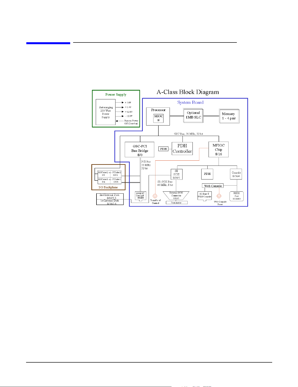
A-Class Server System Block Diagram
A-Class Server System Block Diagram
Overview
The A-Class server block diagram is included for information.
12
Chapter 1
Page 13

A-Class System Overview and Reference
A-Class Server System Regulatory Compliance Statements
A-Class Server System Regulatory Compliance
Statements
Overview
Regulatory Compliance statements are required by some countries for international
importation of A-Class servers. The following information is provided:
• Regulatory Information
• Safety
•Declaration of Conformity
• FCC STATEMENT (USA Only)
• FCC Regulations for Telephone Line Interconnection
• Canada RFI Statement
• European Union RFI Statement
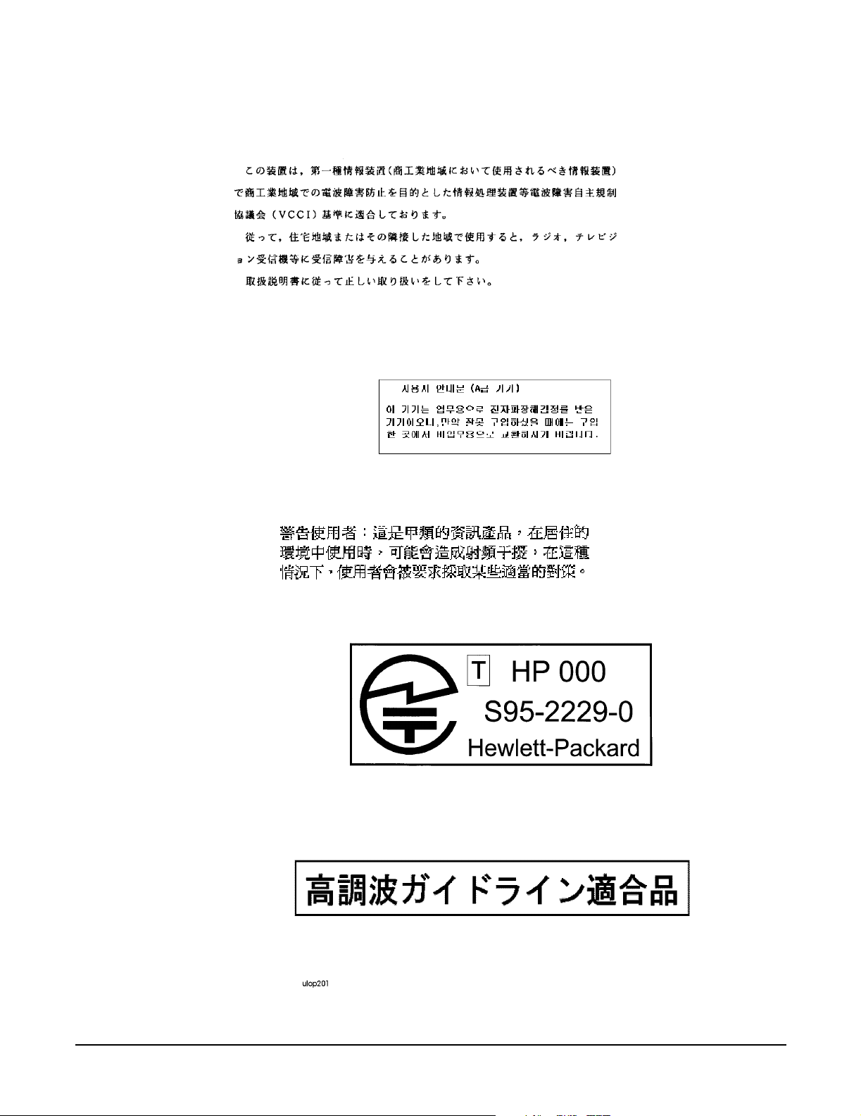
• Japan RFI Statement
• Korean RFI Statement
• Taiwan RFI Statement
•Japan-Only JATE Mark
• Japan Harmonic Statement
• Acoustics (Germany)
• UK General Approval (United Kingdom only)
• Internal Modem and HP A2991-600xx Line Access Module (LAM)
• Terminal DOC (Canada only)
• National Post and Telecom Agency Statement (Sweden only)
• AUSTEL Telecom Statement (Australia only)
• New Zealand and Telecom Statement (New Zealand only)
Chapter 1
13
Page 14

A-Class System Overview and Reference
A-Class Server System Regulatory Compliance Statements
Regulatory Information
For your protection, this product has been tested for conformance to various national and
international regulations and standards. The scope of this regulatory testing includes
electrical and mechanical safety, electromagnetic emissions, immunity, acoustics and
hazardous materials.
When required, approvals are obtained from third party test agencies. Approval marks
appear on the product label. In addition, various regulatory bodies require some
information under the headings listed in this section.
Safety
This product has not been evaluated for connection to an “IT” power system (ac
distribution system having no direct connection to earth according to IEC 950).
Locate the AC outlet near the computer! The ac power cord is this product's main ac
disconnect device and must be easily accessible at all times.
Battery Notice
This product contains a Lithium battery.
This battery is not to be removed or replaced by the user. If the battery needs to be
replaced, contact your Hewlett-Packard authorized service personnel.
CAUTION Lithium batteries may explode if mistreated. Do not recharge, disassemble, or dispose of
in a fire.
Please properly recycle all used batteries.
14
Chapter 1
Page 15

A-Class System Overview and Reference
A-Class Server System Regulatory Compliance Statements
Declaration of Conformity
FCC STATEMENT (USA Only)
The United States Federal Communications Commission has specified that the following
notice be brought to the attention of users of this product:
NOTE This equipment has been tested and found to comply with the limits for a Class A digital
device, pursuant to part 15 of the FCC rules. These limits are designed to provide
reasonable protection against harmful interference when the equipment is operated in a
commercial environment. This equipment generates, uses, and can radiate radio
frequency energy and, if not installed and used in accordance with the instruction
manual, may cause harmful interference to radio communications. Operation of this
equipment in a residential area is likely to cause harmful interference in which case the
user will be required to correct the interference at his own expense.
Hewlett-Packard's system verification tests were conducted with HP-supported
peripheral devices and HP shielded cables, such as those you receive with your computer.
Changes or modifications not expressly approved by Hewlett-Packard could void the
user's authority to operate the equipment. Cables used with this device must be properly
shielded to comply with the requirements of the FCC.
FCC Regulations for Telephone Line Interconnection
• This equipment complies with Part 68 of the FCC rules. On the outside surface of
this equipment is a label that contains, among other information, the FCC
registration, the FCC registration number and ringer equivalence number (REN). If
requested, this information must be provided to the telephone company.
• This equipment uses the following Universal Service Code (USOC) jacks: RJ11C or
RJ11W (single line).
• The REN is used to determine the quality of devices which may be connected to the
telephone line. Excessive RENs on the telephone line may result in the devices not
ringing in response to an incoming call. In most, but not all areas, the sum of the
RENs should not exceed five (5.0). To be certain of the number of devices that may be
connected to the line, as determined by total RENs, contact the telephone company
to determine the maximum REN for the calling area.
• If this equipment causes harm to the telephone network, the telephone company
will, where practicable, notify you in advance that temporary discontinuance of
service may be required. If advance notice isn’t practical, the telephone company will
notify the customer as soon as possible. Also, you will be advised of your right to file
a complaint with the FCC if you believe it is necessary.
• The telephone company may make changes in its facilities, equipment, operations, or
procedures that could affect the operation of the equipment. If this happens, the
telephone company will provide advance notice in order for you to make the
necessary modifications in order to maintain uninterrupted service.
Chapter 1
• If trouble is experienced with this equipment, please contact: Hewlett-Packard
Company, Response Center, 20 Perimeter Summit Boulevard, Atlanta, GA 30319
U.S.A. 1 (800) 633-3600 (Toll Free - North America Only) or 1 (404) 648-0000 (Main
Number)
15
Page 16

A-Class System Overview and Reference
A-Class Server System Regulatory Compliance Statements
for repair and/or warranty information. If the trouble is causing harm to the
telephone network, the telephone company may request that you remove the
equipment from the network until the problem is resolved.
• No repairs are to be made by you. Repairs are to be made only by Hewlett-Packard or
its licensees. Unauthorized repairs void registration and warranty.
• This equipment cannot be used on telephone company-provided coin service.
Connection to Party Line Service is subject to state tariffs. (Contact the state public
utility commission, public service commission, or corporation commission for
information).
• If so required, this equipment is hearing-aid compatible.
Canada RFI Statement
• This Class A digital apparatus meets all requirements of the Canadian
Interference-Causing Equipment Regulations.
• Cet appareil numÅrique de la classe A respecte toutes les exigences du RÉglement
sur le matÅriel brouilleur du Canada.
European Union RFI Statement
This is a Class A product. In a domestic environment, this product may cause radio
interference in which case the user may be required to take adequate measures.
16
Chapter 1
Page 17
Japan RFI Statement
Korean RFI Statement
A-Class System Overview and Reference
A-Class Server System Regulatory Compliance Statements
Taiwan RFI Statement
Japan-Only JATE Mark
Japan Harmonic Statement
Chapter 1
17
Page 18

A-Class System Overview and Reference
A-Class Server System Regulatory Compliance Statements
Acoustics (Germany)
Acoustic noise level per ISO 9296 (25° C):
LpA
<57dB (operators position)
m
GerÌuschemission nach ISO 9296 (25° C):
LpA
<57dB (Arbeitsplatte)
m
UK General Approval (United Kingdom only)
Pursuant to Section 22 of Telecommunications Act of 1984, this product is approved for
indirect connection to Public Telecommunications systems within the United Kingdom
under the General Approval number NS/G/1234/J/100003.
Internal Modem and HP A2991-600xx Line Access Module (LAM)
The following warnings apply to the use of the HP 2991-60001 internal modem and HP
A2991-600xx LAM that may be provided with the computer.
Terminal DOC (Canada only)
NOTE The Canadian Department of Communications label identifies certified equipment. This
certification means that the equipment meets certain telecommunication network
protective operational and safety requirements. The Department does not guarantee the
equipment will operate to the user's satisfaction.
Before installing this equipment, users should ensure that it is permissible to be
connected to the facilities of the local telecommunications company. The equipment must
also be installed using an acceptable method of connection. In some cases, the company's
inside wiring associated with a single line individual service may be extended by means
of a certified assembly (telephone extension cord). The customer should be aware that
compliance with the above conditions may not prevent degradation of service in some
situations.
Repairs to certified equipment should be made by an authorized Canadian maintenance
facility designated by the supplier. Any repairs or alterations made by the user to this
equipment, or equipment malfunctions, may give the telecommunications company
cause to request the user to disconnect the equipment.
Users should ensure for their own protection that the electrical ground connections of
the power utility, telephone lines and internal metallic water pipe system, if present, are
connected together. This precaution may be particularly important in rural areas.
The Load Number (LN) assigned to each terminal device denotes the percentage of total
load to be connected to a telephone loop which is used by the device to prevent
overloading. The termination on a loop may consist of any combination of devices subject
only to the requirement that the total of the Load Numbers of all devices does not exceed
100. The load number for this product is 33.
18
Chapter 1
Page 19
A-Class System Overview and Reference
A-Class Server System Regulatory Compliance Statements
CAUTION Users should not attempt to make such connections themselves, but should contact the
appropriate electric inspection authority, or electrician, as appropriate.
National Post and Telecom Agency Statement (Sweden only)
The LAM Interface shall be connected to SELV (max.42.4 V peak, or 60 V DC) according
to EN 60950. (The internal modem complies with this requirement.)
AUSTEL Telecom Statement (Australia only)
When setting the number of automatic redials for the modem, ensure the following:
The number of automatic redials that the modem performs should be limited to a
maximum of 9 redials plus the original call. If the above retries are unsuccessful, no
further attempts should be made to the same number for a minimum period of 5
minutes.
CAUTION Failure to set the modem, and any communication software used with the modem to the
values contained in the listing will result in the modem being operated in a
non-compliant manner. Consequently, there would be no permit in force for this
equipment, and the Telecommunications Act 1991 prescribes a penalty of A$12,000 for
the connection of non-permitted equipment.
Australian C-Tick Label
New Zealand and Telecom Statement (New Zealand only)
When using an application software that allows the setting of automatic redialing, the
following guidelines should be followed:
• Not more than five call attempts to the same number within a one hour period.
• A minimum of 60 seconds between each attempt.
• Not more than a total of 10 call attempts to the same number.
Any setting that violates the above guidelines will cause the equipment to go out of
compliance, and thus no Telepermit will be in force for this equipment which will make it
subject to penalties.
Chapter 1
19
Page 20

A-Class System Overview and Reference
A-Class Server System Regulatory Compliance Statements
The operation of this equipment on the same line as telephones or other equipment with
audible warning devices or automatic ring detectors will give rise to bell tinkle or noise
and may cause false tripping of the ring detector. Should such problems occur, the user is
not to contact Telecom Faults Service.
20
Chapter 1
Page 21

2 A-Class Server Installation
A-Class Server Installation
Chapter 2
21
Page 22

A-Class Server Installation
A-Class Server System Installation
A-Class Server System Installation
Overview
The sections listed below describe the procedures you will use to prepare for, install, and
begin operation of, your A-Class server:
A-Class Server Site Preparation. Contains environmental requirements for
preparing the area where your server is to be located.
Stand-Alone A-Class Server Unpack and Install Instructions. Details what you will
find when you open the carton containing your A-Class server and how to set it up
for stand-alone operation.
Cabinet-Mounted A-Class Server System Unpack and Install. Tells you how to
install and connect the server to external devices and power, either as a stand-alone
unit or in an HP-supported cabinet. Unpacking, set up, and connection information
is also included for those who ordered a cabinet from the factory with one or more
servers installed,
A-Class Server System Software Configuration. Tells you how to install memory
(RAM), cache memory, embedded disk and I/O card add-on components.
A-Class Server Power Up and Boot Procedures. Leads you through the process for
powering up external devices and the server, gives the software commands for
customizing the A-Class Secure Web Console IP address, and lists the steps required
for booting the server to an operating state.
A-Class Server System Software Configuration. Directs you to the software
commands necessary for preparing both the A-Class server and the A-Class Secure
Web Server for operation.
22
Chapter 2
Page 23

A-Class Server Installation
A-Class Server Site Preparation
A-Class Server Site Preparation
Overview
This section contains the following environmental requirements for preparing a site for
the A-Class Server:
Space Requirements. Space requirements for both stand-alone and cabinet-mounted
A-Class servers.
Input Power Requirements. Nominal input voltage, nominal frequency, and typical
current requirements.
Cooling Requirements. Operating and non-operating temperature extremes and
relative humidity parameters.
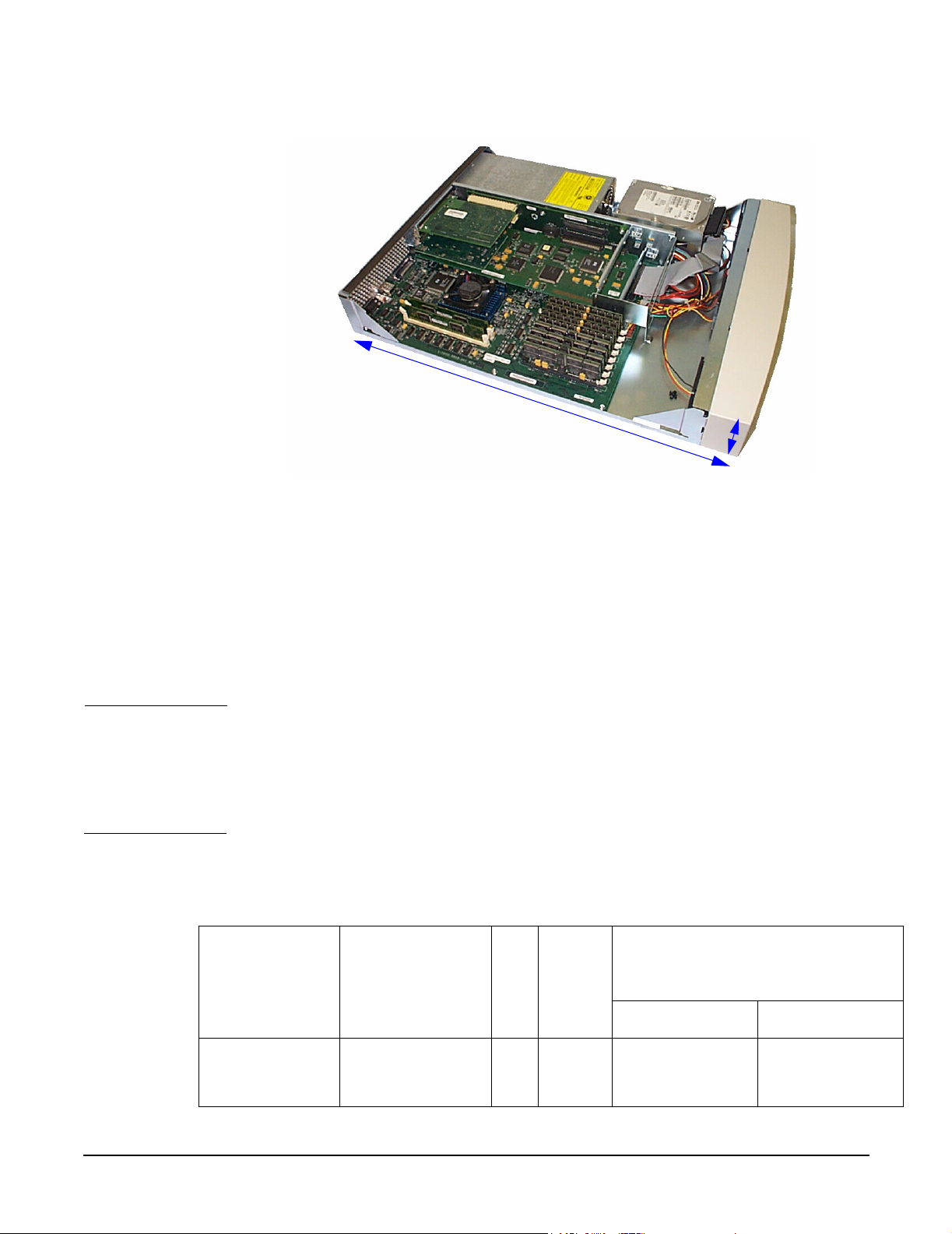
Space Requirements
Stand-Alone Server Dimensions
The physical characteristics of the A-Class server are listed as follows:
Dimension
Height 8.89 cm (3.5 in.)
Width 43.18
cm
Depth 58.42
cm
Weight 9.98kg (22 lbs)
(17 in.)
(23 in.)
Chapter 2
23
Page 24
A-Class Server Installation
A-Class Server Site Preparation
Stand-Alone Server Minimum Service Access Requirements
23” (58.42cm)
Access
Location
Rear 15 cm (6 in.)
Sides 7.5 cm (3 in.)
Front 7.5 cm (3 in.)
CAUTION Stacking A-Class servers in any manner and mounting in any cabinet other than a
Hewlett-Packard approved cabinet, is not supported.
While they are constructed to be strong, A-Class servers have not been tested for
stacking load carrying capacity. Failure to follow this precaution may result in major
damage to the server.
Cabinet Dimensions
A-Class servers can be installed in any of the following cabinets:
Max.
Cabinet
Product
Number
Description
EI
A
A-Clas
s
Server
s
External Dimensions (width x
depth x height)
Centimeters Inches
24
A4900A Factory
Integrated 1.25m
x 19” Cabinet
25 12 59.7 x 100.3 x
125.7
23.5 x 39.5 x 49.5
Chapter 2
Page 25
Cabinet
Product
Number
Description
EI
A
Max.
A-Clas
s
Server
s
A-Class Server Installation
A-Class Server Site Preparation
External Dimensions (width x
depth x height)
Centimeters Inches
A4901A Factory
Integrated 1.6m x
19” Cabinet
A4902A Factory
Integrated 2.0m x
19” Cabinet
J1502A Field Integrated
1.25m x 19”
Cabinet
J1501A Field Integrated
1.6m x 19”
Cabinet
J1500A Field Integrated
2.0m x 19”
Cabinet
C2785A Field Integrated
1.1m x 19”
Cabinet
C2786A Field Integrated
1.6m x 19”
Cabinet
33 16 59.7 x 100.3 x
161.3
41 20 59.7 x 100.3 x
196.9
25 12 59.7 x 100.3 x
125.7
33 16 59.7 x 100.3 x
161.3
41 20 59.7 x 100.3 x
196.9
21 10 61 x 91.4 x 111.8 24 x 36 x 44
32 16 61 x 91.4 x 162.6 24 x 36 x 64
23.5 x 39.5 x 63.5
23.5 x 39.5 x 77.5
23.5 x 39.5 x 49.5
23.5 x 39.5 x 63.5
23.5 x 39.5 x 77.5
Chapter 2
C2787A Field Integrated
2.0m x 19”
Cabinet
Cabinet Minimum Service Access Requirements
Access
Location
Rear 61 cm (24 in.)
Sides NA (NA)
Front 100.3 (39.5
41 20 61 x 91.4 x 203.2 24 x 36 x 80
in.)
Input Power Requirements
Input power requirements for the A-Class server are listed as follows:
• Nominal Input Voltage (VAC): 100 - 240
25
Page 26

A-Class Server Installation
A-Class Server Site Preparation
• Nominal Frequency: 50 or 60 Hz
• Typical current requirements:
If an Uninterruptible Power Supply (UPS) is to be used, ensure that it is properly
connected to the server. Refer to the, External Connections section for UPS information.
Power cord plugs for stand-alone servers are configured to meet unique power
configurations used all over the world.
Cabinet-mounted servers have the same power requirements as stand-alone servers.
However, the power cords for cabinets are dependent on the type of Power Distribution
Unit (PDU) operation.
PDU power cords with one end stripped are also available for attaching country-specific
power plugs. Refer to the cabinet documentation for more electrical power information.
Cooling Requirements
1.0A at 100V
0.43A at 240V.
Temperature Parameters
The operating and non-operating temperatures shown below are the extremes at which
server parameters have been established.
Operating Non-Operati
ng
+5°-+35°C
(41° - 95°F)
Relative Humidity
Operating and non-operating relative humidity parameters are shown below:
Operating Relative
Humidity
15% to 80%,
non-condensing
-40° - +65°C
(-40° - 149°F)
Non-Operating Relative
Humidity
5% to 90%, non-condensing
26
Chapter 2
Page 27

A-Class Server Installation
Stand-Alone A-Class Server Unpack and Install Instructions
Stand-Alone A-Class Server Unpack and Install
Instructions
Overview
Unpacking the A-Class server consists of opening and unloading the carton. Inside the
carton you will find, in addition to the server, an accessory kit and a packet containing
installation instructions and regulatory information.
• Open and Unload the Carton
•Unpack the Server
• Open the Accessory Kit
• Open the Installation Instructions and Regulatory Information Packet
NOTE The following instructions do not apply to A-Class servers that are received pre-installed
in a cabinet. These procedures pertain to individual servers, only.
Open and Unload the Carton
Step 1. Place the sealed carton on a work surface with the correct side up as indicated by the
“This Side Up” symbol (below).
CAUTION Use sharp instruments carefully when unpacking electronics equipment. Failure to
follow this precaution may result in personal injury or damage to components.
Step 2. Carefully open the carton, remove the contents, and set them on the work surface. Each
carton will contain:
• The server.
• An accessory kit.
• A packet containing installation instructions and regulatory information.
NOTE Report any missing items to your local Hewlett-Packard office immediately. If there is
obvious freight damage, contact your shipper immediately.
Chapter 2
We recommend that you retain all packing materials in case any of the items received
require return to Hewlett-Packard.
27
Page 28

A-Class Server Installation
Stand-Alone A-Class Server Unpack and Install Instructions
Unpack the Server
CAUTION Do not set the server on its side, or in any position other than upright on its rubber
“feet,” for operation. Failure to observe this precaution may result in component damage
or loss of system reliability.
Carefully unwrap the server and set it upright on the work surface.
Open the Accessory Kit
Open the Accessory Kit and verify that the contents agree with the packing list.
NOTE Plastic Front Anchor Bracket end caps are included in each kit. Do not discard them.
They will be needed if the server is installed in a cabinet.
Open the Installation Instructions and Regulatory Information Packet
The Installation Instructions/Regulatory Information Packet contains the following
information:
• Installation Instruction Sheet (A5182-96002), which includes:
Basic cable connection information necessary to power on and boot the server to
the Firmware Main Menu screen.
The Universal Resource Locator (URL) for the A-Class Server home page on the
World Wide Web.
• Regulatory Information. Contains consumer safety and regulatory statements for
the United States and for those countries that require publishing and dissemination
of their own consumer safety and regulatory data.
Installing a Stand-alone System
A-Class servers are compact in design and can be installed on table or desk tops in the
same manner as any standard Personal Computer (PC).
Heating and cooling conditions must be met for the system to function at peak efficiency.
Attention must be paid to system access. There must be room for external connections on
the rear of the server and there must be ready access to an electrical outlet with the
correct electrical output. These environmental requirements are found in the section
titled, A-Class Server Site Preparation.
28
When you have installed the server and are ready to connect external devices, refer to
the,External Connections section.
To power up and boot the server, refer to the section titled, A-Class Server Power Up and
Boot Procedures.
Chapter 2
Page 29

A-Class Server Installation
Cabinet-Mounted A-Class Server System Unpack and Install
Cabinet-Mounted A-Class Server System Unpack and
Install
Overview
A-Class servers can be procured in two modes: stand-alone or pre-installed in a cabinet
at the factory. Stand-alone servers can be configured for installation in an existing
HP-supported cabinet. The following subsections provide system installation
information:
• Information Sheet
• Installing a Factory-integrated Cabinet
• Installing a Stand-alone System in an HP-supported Cabinet
• External Connections
Information Sheet
Each system is packed with an Information Sheet that contains basic installation
instructions. Review the Information Sheet thoroughly and follow the steps listed to
perform the installation. The information sheet may refer you to the LED Interpretation
and Removal & Replacement Procedures label located inside the cover, adhered to the
top. This label provides instructions for interpreting LED combinations and information
about system components.
Installing a Factory-integrated Cabinet
Unpacking the Cabinet
NOTE It is the customer's responsibility to inspect the shipping package for damage.
It is the Hewlett-Packard Customer Engineer’s responsibility to remove the cabinet
assembly from the shipping pallet.
WAR NING A fully configured 2.0 meter cabinet can weigh up to 362.8 kg (800 lbs). Be
careful not to tip the cabinet while unpacking. Failure to heed this warning
can result in serious injury or equipment destruction.
Chapter 2
To unpack the cabinet, perform the following steps:
29
Page 30
A-Class Server Installation
Cabinet-Mounted A-Class Server System Unpack and Install
WAR NING Wear protective glasses while cutting the plastic bands around the shipping
container. These bands are under tension. Failure to heed this warning can
result in serious eye injury if the bands snap back and hit you in the face when
cut.
Step 1. Cut the plastic polystrap bands around the shipping container.
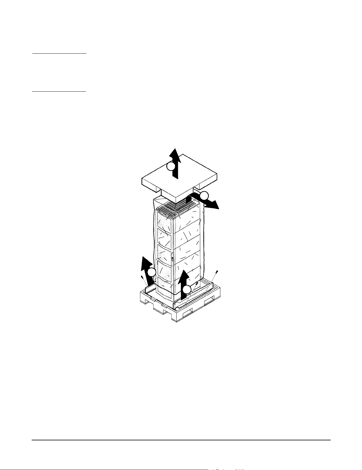
Step 2. Lift the cardboard top cap off of the shipping box (callout 1) and remove the packing
material underneath (callout 2). Remove the screws that secure the ramps in place and
lift the ramps out (callout 3).
1
2
3
3
3
30
Chapter 2
Page 31

Cabinet-Mounted A-Class Server System Unpack and Install
Step 3. Remove the brackets securing the cabinet to the pallet (callout 4).
4
4
4
A-Class Server Installation
Step 4. Insert the ramps in the notches provided on the pallet (callout 5). Remove the side
panels from the cabinet and set them aside (callout 6).
6
6
5
5
5
Chapter 2
31
Page 32

A-Class Server Installation
Cabinet-Mounted A-Class Server System Unpack and Install
WAR NING
A fully configured 2.0 meter cabinet can weigh up to 362.8 kg (800 lbs). Always
use at least two people to roll the cabinet off of the pallet. Failure to heed this
warning can result in serious injury or equipment destruction.
Step 5. Use at least two people to roll the cabinet off of the pallet and down the ramp (callout 7).
7
Cabinet Inspection
Once the cabinet is off the shipping pallet, but before moving it to the installation site,
inspect the internal and external condition of the cabinet.
Cabinet Exterior Checklist:
Check the cabinet exterior for signs of shipping damage:
• Look at the top and sides for dents, warpage, or scratches.
32
• Check the front bezels for alignment, scratches, and that they open and close
normally.
• Check any filler panels on the front of the cabinet, for proper fit.
• Check the forehead assembly for any signs of damage.
Chapter 2
Page 33

A-Class Server Installation
Cabinet-Mounted A-Class Server System Unpack and Install
• Check the rear door for dents, scratches, proper fit when its closed, and operation.
Cabinet Interior Checklist: Open the rear door and inspect the inside of the cabinet:
• Inspect all cables, make sure they are secure.
• Inspect all rails for signs of damage.
• Check all mounting screws for tightness.
• Check all components for signs of shifting during shipment or any signs of damage.
NOTE If the shipment is incomplete, or if the equipment is damaged or fails to meet
specifications, notify the nearest Hewlett-Packard Sales and Support Office. If damage
occurred in transit, notify the carrier as well. Hewlett-Packard will arrange for
replacement or repair without waiting for settlement of claims against the carrier. If the
shipment was damaged in transit, keep the shipping containers and packaging material
for inspection.
If extensive damage is found, it may be necessary to return the entire cabinet to HP.
Refer to the Repacking instructions.
Cabinet Installation
Installation of a factory-loaded cabinet consists of the following steps:
Step 1. Move the cabinet to installation site.
Step 2. Lower the leveling feet. (This will prevent excessive wear on the casters.)
CAUTION Extend the cabinet stabilizers, located at the bottom of the front of the cabinet, as an
additional safeguard against overturning the cabinet during installation. Failure to
observe this precaution could result in personal injury or equipment damage.
Step 3. Connect the console and system peripherals to the server.
For information about connecting external devices, refer to External Connections at the
end of this section.
NOTE Attaching cables while the rails are extended fully forward will ensure that sufficient
slack is available for later maintenance.
Step 4. Connect the cabinet power cord to the appropriate wall outlet.
NOTE If the cabinet being installed contains a PowerTrust Uninterruptible Power Supply
(UPS), perform the steps shown under the PowerTrust UPS OptionOption subsection.
Step 5. Be sure all peripherals outside the cabinet are connected to wall outlets.
Chapter 2
33
Page 34

A-Class Server Installation
Cabinet-Mounted A-Class Server System Unpack and Install
The cabinet/server system assembly is now ready for the power up process. Refer to the
section titled, A-Class Server Power Up and Boot Procedures.
PowerTrust UPS Option
Unpack the PowerTrust UPS and read all the installation information in the PowerTrust
System Guide, part number 5961-8383. Once all the procedures listed in the UPS guide
are complete, perform the following steps to complete the UPS installation with the
cabinet.
1. Position the UPS next to the cabinet on the floor.
2. Remove the jumper cord from the SPU to the PDU inside the cabinet.
3. Install one of the convenience cords (output cord) that came with the UPS into the
AC receptacle in the back of the SPU.
4. Place the other end of that cord into one of the Output outlets in the back of the UPS.
5. The other convenience cord is connected between the UPS and the system console.
6. Locate the appropriate input line cord for the UPS in the supplemental package
shipped with the UPS.
7. Plug the UPS into the appropriate wall outlet.
WAR NING
8. The system should now be ready for power up. Refer to the section titled, A-Class
Server Power Up and Boot Procedures.
Repackaging the Cabinet for Shipment
Use the original packing material to repackage the cabinet for shipment. If the packing
material is not available, contact your local Hewlett-Packard Sales and Support Office
regarding shipment.
Before shipment, place a tag on the container (or equipment) to identify the owner and
the service to be performed. Include the equipment model number and the full serial
number, if applicable. The label showing the model number and the full serial number is
located on the outside of the rear door.
Due to the weight of a fully loaded cabinet, it will require two people to push the cabinet
up the ramp onto the pallet.
34
Repackaging a loaded cabinet may be hazardous because a fully configured 2.0
meter cabinet can weigh up to 362.8 kg (800 lbs). Always use two people when
moving the cabinet and when positioning the cabinet on the pallet. Check the
condition of the loading/unloading ramp before use. If the ramp appears
damaged, DO NOT attempt to push a loaded cabinet up the ramp onto the
Chapter 2
Page 35

A-Class Server Installation
Cabinet-Mounted A-Class Server System Unpack and Install
pallet. Contact your local Hewlett-Packard Sales and Support Office regarding
shipment. Failure to heed this warning can result in serious injury or
equipment destruction.
To repackage the cabinet, follow the repacking checklist and refer to the unpacking
instructions for detail.
Repacking Checklist:
• Assemble the HP packing materials that came with the cabinet.
• Connect the loading ramp to the pallet.
• Raise the cabinet levelers before moving the cabinet.
• Push the cabinet up the ramp onto the pallet. Be sure to position the cabinet so that
the front goes up the ramp first.
• Secure the cabinet to the pallet with the shipping clamps, shipping block, and rear
door support.
• Place the anti-static bag over the cabinet.
• Place bezel support packing on the front corners of the cabinet. Secure it with a
wrap.
• Place the top cap packing material and loading/unloading ramp on top of the cabinet.
• Wrap the clam shell box around the cabinet.
• Put the box top on the box and secure the assembly to the pallet.
Be sure to follow the tagging and labeling instructions mentioned earlier. The cabinet is
now ready for shipment.
Installing a Stand-alone System in an HP-supported Cabinet
Cabinet Identification
The following cabinets can hold multiple A-Class servers:
Cabinet
Product
Number
A4900A Factory 1.25m x 19” 12 A5180A
A4901A Factory 1.6m x 19” 16 A5180A
A4902A Factory 2.0m x 19” 20 A5180A
J1502A Field 1.25m x 19” 12 A5214A
Assembl
ed by:
Size
(Height x
Width)
Maximum
Servers
Adapter
Kit
Number
Chapter 2
J1501A Field 1.6m x 19” 16 A5214A
J1500A Field 2.0m x 19” 20 A5214A
C2785A Field 1.1m x 19” 10 A5214A
C2786A Field 1.6m x 19” 16 A5214A
35
Page 36

A-Class Server Installation
Cabinet-Mounted A-Class Server System Unpack and Install
Cabinet
Product
Number
C2787A Field 2.0m x 19” 20 A5214A
Cabinet Loading Requirements
A-Class servers require two EIA of cabinet space (each two EIA of space is equivalent to
the height of a server without the server’s “feet”). Ensure that the cabinet has this
amount of space available.
NOTE Replace the rubberized feet on the server with plugs provided in the cabinet mounting
adapter kit.
Fill empty cabinets from the top down, with A-Class servers on top. If you are mounting
one or more servers into an empty cabinet, start at the inside top of the cabinet and
count down four of the holes in the columns at each corner to determine the position of
the rails for the first server. When the first rails are installed, continue to use the four
hole requirement as your guide for installing additional A-Class servers.
Refer to the Rail Kit Installation Sheet (A5214-96001) for instructions necessary to
install rails in the HP computer cabinet.
Assembl
ed by:
Size
(Height x
Width)
Maximum
Servers
Adapter
Kit
Number
Mounting the Server To mount the server in the cabinet, follow the procedure listed
below:
Step 1. From the front of the cabinet, slide the server onto the rails. Push the server into the
cabinet until approximately three inches of the server remains protruding from the
front.
Step 2. Install sheet metal nuts on the left and right front columns and align with front anchor
bracket slots.
Step 3. Install the left and right front anchor brackets on each side of the server as follows:
36
• Insert each hooked tab into its slot on the bottom of the front corner of the server.
Chapter 2
Page 37

A-Class Server Installation
Cabinet-Mounted A-Class Server System Unpack and Install
• Hold the tabs upright and slide the server all the way into cabinet until the tabs butt
up against the columns on each side.
Step 4. Fasten the both front anchor brackets securely to both front cabinet columns with the
prepositioned sheet metal nuts.
Step 5. Attach a plastic end cap to each anchor bracket.
Step 6. At the rear of the cabinet, position the rear rail mounting clamps on each rail at the back
of the server. Tilt each clamp forward slightly and slide the angled tab completely into
the available slot in the server so that each clamp sits flat on the rail.
Step 7. Fasten each rear mounting clamp to its rail with the screws provided.
When you are ready to connect external devices, refer to External Connections for
further information.
Chapter 2
37
Page 38

A-Class Server Installation
Cabinet-Mounted A-Class Server System Unpack and Install
External Connections
External devices are interfaced with the A-Class server by means of specific connectors
located in the rear of the server. Exterior connections to the server include ports for:
• Small Computer System Interface (SCSI) devices
•System Consoles
• Local Area Networks (LANs)
• Power Cords.
38
Connect External Small Computer System Interface (SCSI) Devices
Connect external SCSI devices to the Single Ended SCSI bus (labeled SCSI
(Single-Ended) 8/16/5) on the system card or to additional SCSI interface cards. If
external devices will not be connected to the SCSI bus, make sure the terminator
(1252-3932) is in place.
Make sure all devices on the SCSI bus have a unique address and the last device is
terminated. Refer to the documentation accompanying each device to learn how to set
addresses and where to place terminators.
Chapter 2
Page 39

A-Class Server Installation
Cabinet-Mounted A-Class Server System Unpack and Install
Connect external DDS (Digital Data Storage) tape and DVD/ CDROM drives to A-Class
servers as shown in the diagram below. Connecting these devices in this manner reduces
the likelihood of excessive parity errors and unexpected interrupts from occurring on the
SCSI bus.
Connect a System Console
• Using the ASCII Terminal as a System Console. If an ASCII terminal is to be used as
a system console, connect it to the back of the server with a 24542G cable by
attaching it to the 9- pin male connector labeled, Console 8/16/4.0.
Make sure the keyboard is connected and a power cable is available.
NOTE When the web console is used, the RS232 Console Port (8/16/4.0) is disabled
• Using the Web Console as a System Console. If the Web Console is to be used as a
system console, connect an RJ45 LAN cable to the RJ45 connector labeled, LAN Web
Console, on the back of the server.
NOTE The Web Console has a default Internet Protocol (IP) address of 192.0.0.192. Make
sure that no other device, including other A-Class servers, has this address before
connecting the A-Class server to your LAN.
Connect the Core Local Area Network (LAN)
Connect the 100baseT Core LAN on the system board to your LAN by using an RJ45
LAN cable. Connect the RJ45 LAN cable to the server by attaching it to the RJ45
connector labeled, 10/100 Base-T 8/0/20/0.
Chapter 2
39
Page 40

A-Class Server Installation
Cabinet-Mounted A-Class Server System Unpack and Install
Connect Power Cords
CAUTION Do not press and hold the Web Console Reset button (located on the rear of the server
between the LAN Web Console receptacle and the ASCII terminal receptacle) while
connecting the server power cord. Failure to observe this precaution will cause erasure of
all settings in the Web Console that is connected to the server.
Connect the power cord that is provided with the system to the server. For stand-alone
servers, the power cord will be localized to each country’s power application. If an HP
Uninterruptible Power Supply (UPS) is the power source, use the power cord provided
with the UPS. If an HSC Remote Management card is installed in the server, use the
cable provided with the HP UPS to connect the RS232 serial port to the port labeled
“UPS” on the HSC Remote Management card.
Connect power cords to all external devices at this time with the localized power cord,
cabinet power cord, or the UPS power cord.
For cabinet mounted servers, the server power cord connects to the C13 connector of the
Power Distribution Unit in the cabinet.
40
Chapter 2
Page 41

A-Class Server Installation
Installing Internal Add-On Components
Installing Internal Add-On Components
This section explains how to install internal add-on components into A-Class servers.
Internal add-on components include memory, cache memory, embedded disks and I/O
cards. For cabinet mounted servers, it is necessary to remove the server from the cabinet
to install internal add-on components.
Refer to the appropriate section for internal add-on component installation information:
• Installing Memory (RAM) Modules.
• Installing Cache Memory SIMMs.
• Installing Embedded Disk Drives.
• Installing Input/Output (I/O) Cards.
Installing Memory (RAM) Modules.
This section describes how to install memory (RAM) into A-Class servers. Computer
memory is commonly referred to as Random Access Memory (RAM). The terms RAM and
memory are used interchangeably in this documentation. Abbreviated Memory SIMM
installation instructions also appear on the 11” x 14” maintenance label adhered to the
bottom of the top cover.
A-Class memory is sold as a module. A module is defined as two SIMMs. A-Class servers
support three memory module sizes: 128MB, 256MB and 512MB. The 128MB memory
module consists of two 64MB SIMMS. The 256MB memory module consists of two
128MB SIMMs and the 512MB memory module consists of two 256MB SIMMs. A
memory module occupies two slots. The size (or capacity) of a memory SIMM is printed
along the top edge of the SIMM.
NOTE SIMM is an acronym for Single Inline Memory Module. A SIMM has components on one
side of the card, only.DIMM is an acronym for Dual Inline Memory Module. A DIMM has
components on both sides of the card.The acronym SIMM will be used throughout this
section to refer to either SIMM or DIMM.
A-Class servers provide 8 slots for memory. These slots are labeled in pairs and are
numbered 0a, 0b, 1a, 1b, 2a, 2b, 3a and 3b. The nomenclature for a pair of SIMM slots is
0a/b, 1a/b, 2a/b and 3a/b. The following rules govern the installation memory in A-Class
Servers.
• Memory must be installed in SIMM pairs.
• The capacity of SIMMs must be the same.
• Install SIMMs with the greatest capacity in the lowest slot numbers.
Chapter 2
Follow the steps below to install memory in A-Class servers.
41
Page 42

A-Class Server Installation
Installing Internal Add-On Components
Electrostatic Discharge Precautions.
The procedures in this section require opening the server and exposing the system to
electrostatic discharge. Always observe all electrostatic precautions when working with
components inside or out of the server. Failure to follow these precautions may result in
component damage or loss of system reliability.
• Use a grounding mat and an anti-static wrist strap.
• Wear the anti-static wrist strap to ensure that any accumulated electrostatic charge
is discharged from your body to ground.
Before You Do Anything...
• Power down the system.
• Unplug the server.
NOTE Cabinet-mounted servers must be removed from the cabinet before proceeding.
• Remove the top of the server by unscrewing the knurled captive screws on each side
of the rear of the server. Slide the top back, lift it off, and set it aside.
Step 1. Document which size SIMMs are already installed and in which slots.
Step 2. Determine the size of the memory SIMMs to be installed.
Step 3. If the capacity of the memory SIMMs to be installed is less than or equal to existing
memory, install the new SIMMs in the next available slots.
Step 4. If the capacity of the memory SIMMs to be installed is greater than existing memory,
remove all existing memory RAM Removal, install RAM Replacement, the largest
capacity SIMMs first beginning with slot 0a/b. Continue to add SIMMs in this manner.
Step 5. Proceed to A-Class Server Power Up and Boot Procedures.
Installing Cache Memory SIMMs.
This section describes how to install Cache Memory SIMMs into A-Class servers.
Abbreviated Cache Memory SIMM installation instructions also appear on the 11” x 14”
maintenance label adhered to the bottom of the top cover.
A-Class Cache Memory is sold as a module. A module is defined as two SIMMs. A-Class
servers support a single 1MB Cache Memory module. The 1MB Cache Memory module
consists of two 512MB SIMMs. A Cache Memory module occupies two slots. The size (or
capacity) of the Cache Memory SIMM is printed along the top edge of the SIMM.
NOTE SIMM is an acronym for Single Inline Memory Module. A SIMM has components on one
side of the card, only.DIMM is an acronym for Dual Inline Memory Module. A DIMM has
components on both sides of the card.The acronym SIMM will be used throughout this
section to refer to either SIMM or DIMM.
42
Chapter 2
Page 43

A-Class Server Installation
Installing Internal Add-On Components
A-Class servers provide 2 slots for Cache Memory. The following rules govern the
installation memory in A-Class Servers.
• Cache Memory must be installed in SIMM pairs.
• The capacity of SIMMs must be the same.
Follow the steps below to install Cache Memory in A-Class servers.
Electrostatic Discharge Precautions.
The procedures in this section require opening the server and exposing the system to
electrostatic discharge. Always observe all electrostatic precautions when working with
components inside or out of the server. Failure to follow these precautions may result in
component damage or loss of system reliability.
• Use a grounding mat and an anti-static wrist strap.
• Wear the anti-static wrist strap to ensure that any accumulated electrostatic charge
is discharged from your body to ground.
Before You Do Anything...
• Power down the system.
• Unplug the server.
NOTE Cabinet-mounted servers must be removed from the cabinet before proceeding.
• Remove the top of the server by unscrewing the knurled captive screws on each side
of the rear of the server. Slide the top back, lift it off, and set it aside.
Step 1. Install the first 512MB Cache Memory SIMM in either unoccupied slot.
Step 2. Install the second 512MB Cache Memory SIMM in the remaining unoccupied slot.
Step 3. Proceed to A-Class Server Power Up and Boot Procedures.
Installing Embedded Disk Drives.
This section describes how to install embedded disk drives into A-Class servers.
Abbreviated embedded disk drive installation instructions also appear on the 11” x 14”
maintenance label adhered to the bottom of the top cover.
A-Class servers support up to two embedded disk drives. As of April 2000, disk capacities
of 4GB, 9GB and 18GB are supported.
Follow the steps below to install embedded disk drives in A-Class servers.
Chapter 2
Electrostatic Discharge Precautions.
The procedures in this section require opening the server and exposing the system to
electrostatic discharge. Always observe all electrostatic precautions when working with
components inside or out of the server. Failure to follow these precautions may result in
component damage or loss of system reliability.
43
Page 44

A-Class Server Installation
Installing Internal Add-On Components
• Use a grounding mat and an anti-static wrist strap.
• Wear the anti-static wrist strap to ensure that any accumulated electrostatic charge
is discharged from your body to ground.
Before You Do Anything...
• Power down the system.
• Unplug the server.
NOTE Cabinet-mounted servers must be removed from the cabinet before proceeding.
• Remove the top of the server by unscrewing the knurled captive screws on each side
of the rear of the server. Slide the top back, lift it off, and set it aside.
Step 1. Remove the disk carrier by removing the slotted T15 TORX screw and slide the disk
carrier upward and toward the power supply.
Step 2. If an embedded disk is already installed, disconnect the power and data cables from that
disk. Place the disk carrier on a ESD safe mat.
Step 3. Set address and configuration jumpers on the disk to be installed. The lower disk is
usually the boot disk and the recommended address is 6. The upper disk is recommended
to be address 5. DO NOT use address 7 as this address is reserved for the SCSI
controller internal to the server. The SCSI controller address of 7 can not be modified.
Step 4. Check configuration jumpers existing disks. Make sure the TERMINATION ENABLED
jumper is removed.
NOTE The TERMINATION ENABLED jumper must be REMOVED on all
embedded disk drives. Failure to remove this jumper will prevent
the SCSI bus from operating properly. Symptoms include failing to
boot from the embedded disk drives when external devices are
connected to the “SCSI (Single Ended) 8/16/5 path”.
44
Chapter 2
Page 45

A-Class Server Installation
Installing Internal Add-On Components
Chapter 2
Set the upper drive to ID to 5
Set the lower drive to ID to 6
Step 5. Install the first embedded disk drive in the lower slot and the second embedded disk in
the upper slot of the disk carrier. Orient the disk drive and the carrier such that the
power and data connectors on the disk drive are on the same side as the sheetmetal tabs.
Slide the disk drive into the carrier and secure the disk drive to the disk carrier with the
four slotted T15 TORX screws that came with the disk drive.
Step 6. Attach power and data cables to the embedded disk drives.
45
Page 46

A-Class Server Installation
Installing Internal Add-On Components
Step 7. Install the disk carrier by inserting the two sheetmetal tabs on the disk carrier into the
cut-outs in the server chassis. Secure the disk carrier using the slotted T15 TORX screw
removed in step 1.
Step 8. Proceed to A-Class Server Power Up and Boot Procedures.
Installing Input/Output (I/O) Cards.
This section describes how to install I/O cards into A-Class servers. Abbreviated
embedded PCI I/O card installation instructions also appear on the 11” x 14”
maintenance label adhered to the bottom of the top cover.
A-Class servers provide two slots for I/O cards. The cards which plug into these slots can
be Peripheral Component Interconnect (PCI), High Speed Connect (HSC) I/O cards or
both (see photo).
The following rules govern the installation of I/O cards:
• When present, the A3342A HSC Remote Management I/O card must be installed in
the bottom slot.
• For one HSC and one PCI card configurations, the HSC card must be installed in the
bottom slot.
• For two HSC or two PCI cards, the load order does not matter.
NOTE When the A3342A HSC Remote Management card is installed, the console path changes
from 8/16/4 to 8/4/0. This may prevent HP-UX from booting.
During selftest, server firmware detects the presence or absence of the A3342A HSC
Remote Management card and will automatically direct server firmware output to the
appropriate path (8/4/0.0 when the A3342A is present, 8/16/4.0 when the A3342A is
absent). These path changes are transparent to the physical console which should be
connected to the server via the connector labeled “Console 8/16/4.0”. These path changes
are also transparent to the server firmware ‘CONSOLE PATH’ value. Server firmware
will not change the ‘CONSOLE PATH’ value. It is not necessary to manually change the
‘CONSOLE PATH’ value when installing or removing the A3342A. You may do so if you
chose.
46
Chapter 2
Page 47

A-Class Server Installation
Installing Internal Add-On Components
Example: A3342A is not installed. ‘CONSOLE PATH’ value is 8/16/4. Server firmware
directs output to 8/16/4.0. Install A3342A. The ‘CONSOLE PATH’ value is still 8/16/4 but
server firmware directs output to 8/4/0.0. Where the console is connected never changes.
NOTE When the A3342A HSC Remote Management card is installed, do not move the console
cable from the server connector labeled “Console 8/16/4.0” to the 9-pin connector on the
A3342A HSC Remote Management card. This connector is for UPS use only.
While server firmware can automatically respond to presence or absence of the A3342A
HSC Remote Management card, HP-UX can not. If HP-UX was installed without a
A3342A HSC Remote Management card installed, the HP-UX path for the console will
be 8/16/4.0. If an A3342A HSC Remote Management card is installed, the path changes
to 8/4/0.0. The driver for this path is mux2. If mux2 is not configured to be ‘in’, HP-UX
will no longer communicate with the console. The symptom is that the server boots from
the root disk, displays the following message then hangs;
Trying Primary Boot Path
------------------------
Booting
Boot IO Dependent Code (IODC) revision 144
HARD Booted.
ISL Revision A.00.38 OCT26, 1994
ISL booting hpux
Boot
:disk (8/16/5.6.0.0.0.0.0;0)/stand/vmunix
3605260 + 327680 + 408736 start 0x16b2e8
To correct this condition, remove the A3342A Remote Management card, boot HP-UX,
run SAM and configure the mux2 driver to be ‘in’. If necessary, refer to the web-based
information at http://docs.hp.com
A3342A Remote Management card can be installed after the mux2 driver has been
verified to be ‘in’.
Follow the steps below to install I/O cards in A-Class servers.
for instructions on how to perform this task. The
Chapter 2
Electrostatic Discharge Precautions.
The procedures in this section require opening the server and exposing the system to
electrostatic discharge. Always observe all electrostatic precautions when working with
components inside or out of the server. Failure to follow these precautions may result in
component damage or loss of system reliability.
47
Page 48

A-Class Server Installation
Installing Internal Add-On Components
• Use a grounding mat and an anti-static wrist strap.
• Wear the anti-static wrist strap to ensure that any accumulated electrostatic charge
is discharged from your body to ground.
Before You Do Anything...
• Power down the system.
• Unplug the server.
NOTE Cabinet-mounted servers must be removed from the cabinet before proceeding.
• Remove the top of the server by unscrewing the knurled captive screws on each side
of the rear of the server. Slide the top back, lift it off, and set it aside.
Step 1. If necessary, remove I/O card brackets. Refer to A-Class Server I/O Card Removal and
Replacement.
Step 2. Carefully insert the I/O card into the backplane connector. The tab on the bulkhead will
slide into its slot in the chassis.
Step 3. Attach the card support guide to the front edge of the I/O card, hook the tab into its slot,
and secure the support guide with the mounting screw.
Step 4. Slide the bulkhead slotted tab up into position between the captive screw and chassis,
and tighten the captive screw.
48
Chapter 2
Page 49

A-Class Server Installation
A-Class Server Power Up and Boot Procedures
A-Class Server Power Up and Boot Procedures
Overview
This Section discusses the following power up and boot procedures:
• Power Up All External Devices
• Power Up the Server
• Configuring the integrated A-Class Web Console. This procedure includes:
— Configuring The Web Browser Host
— Configure the Web Browser
— Configure The integrated A-Class Web Console Software
— Accessing the Secure Web Console
Optional procedures for identifying external devices and mapping diagnostics:
• Boot to Initial System Loader (ISL) (Optional)
• Run Online Diagnostic Environment (ODE) Mapper (Optional)
The command to Boot HP-UX after running either of the preceding options is also
included.
Power Up Procedures
Power Up All External Devices
Apply power to all external devices, such as additional disk drives, Universal Power
Supply, and Digital Data Storage. Observe that each device passes its own selftest and is
ready for operation. Refer to the device-specific documentation as necessary.
Power Up the Server
Apply power to the A-Class server by toggling the rocker power switch on the rear of the
server from the 0 position to the 1 position. All of the front panel LEDs will illuminate
for a moment, then turn off. Only the green power LED will remain illuminated until
power is switched off. If the LEDs do not illuminate or the server does not appear to
power on, refer to Chapter 3, “A-Class System Service,” on page 61.
The server will automatically conduct a selftest and, upon completion, the firmware
Main Menu screen will be displayed at the system console. Only the power LED should
be illuminated at this point.
Chapter 2
If AUTOBOOT is enabled, the system will automatically try to boot HP-UX from the
PRIMARY PATH. If you want to interrupt the boot process, press any key on the
keyboard within 10 seconds after the message, Hit any key to interrupt the boot
sequence is displayed.
49
Page 50

A-Class Server Installation
A-Class Server Power Up and Boot Procedures
Configuring the integrated A-Class Web Console
CAUTION The integrated A-Class Web Console is preconfigured with IP address 192.0.0.192.
Power-off any other devices with the same IP address before proceeding with integrated
A-Class Web Console configuration. Each A-Class server must be configured to the
integrated A-Class Web Console with an individual IP address.
Failure to follow this precaution will result in unexpected behavior of the Local Area
Network (LAN).
Configuring The Web Browser Host
NOTE The A-Class server and the Web Browser Host must be on the same subnet.
Enter the following commands into either a DOS window or UNIX widow on the host
where the browser used to configure the integrated A-Class Web Console resides:
Step 1. Route add 192.0.0.192 <host IP address>.
Step 2. ping 192.0.0.192.
If ping is unsuccessful, proceed to step 3.
If ping is successful, proceed to Configure the Web Browser.
Step 3. arp -s 192.0.0.192 <MAC_ address of integrated A-Class Web Console>.
Step 4. Repeat Step 2.
NOTE Using the arp command requires superuser capability.
The MAC address of the integrated A-Class Web Console appears on the rear label of the
server in a field entitled, “MAC Address.” The MAC address must be entered in the
correct format. For example:
PCs: 00-60-b0-22-3e-ae Unix workstations: 00:60:b0:22:3e:ae
CAUTION DO NOT enter the “LAN Station Address” value (located on the rear label) in place of the
“MAC Address” value (also located on the rear label). If the wrong number is erroneously
entered, use the arp -d command to correct the entry.
50
Failure to follow this precaution will cause the integrated A-Class Web Console to
malfunction.
Chapter 2
Page 51

A-Class Server Installation
A-Class Server Power Up and Boot Procedures
Configure the Web Browser
Enable Java™ on your Web browser (Internet Explorer™ version 3.02 or Netscape
Navigator™, version 3.01 or later).
Temporarily add 192.0.0.192 to the list of URLs in your browser proxy configuration
(under options).
Configure The integrated A-Class Web Console Software
NOTE During the configuration of your Secure web console, you must construct an IP gateway
in the “configure IP” screen. If you do not have a valid IP gateway, enter the same IP
address as you entered for the Secure integrated A-Class Web Console.
Access the integrated A-Class Web Console through your Web browser, located on the
same subnet, by typing the following URL in the “Location:” window: http://192.0.0.192.
The screen shown below will be displayed:
Chapter 2
51
Page 52

A-Class Server Installation
A-Class Server Power Up and Boot Procedures
Press OK to continue. The following administrator account creation screen will appear:
The data required for this screen is defined below:
Name is the full name of the Secure Web Console Administrator.
Function is the job title of the Secure Web Console Administrator.
Information can be used for additional data about the Secure Web Console
Administrator. For example: phone number, location, etc.
Login is the user name of the Secure Web Console Administrator.
Password must be at least six characters in length and must be entered in both
fields.
52
Chapter 2
Page 53

A-Class Server Installation
A-Class Server Power Up and Boot Procedures
When all fields have been completed, the following “Configure IP” screen will appear:
The data required for this screen is defined below:
• Secure Console Name (the name given to the integrated A-Class Web Console)
• IP address (the IP for the integrated A-Class Web Console port)
• IP subnet mask (the IP for the subnet mask for your site)
• IP gateway (the IP gateway address)
• System name (the name given to the A-Class Server).
Chapter 2
53
Page 54

A-Class Server Installation
A-Class Server Power Up and Boot Procedures
After entering this information, press OK. The final screen in this series will appear:
NOTE Disregard step 2, “Connect the serial cable from the system to the Secure Web Console.”
Step 2 applies only to the stand-alone version of the HP Secure Web Console product. In
A-class servers, this product is already installed internally.
Press OK to continue.
NOTE Pressing OK will NOT reboot the A-Class server. It will only reboot the Secure Web
Console. A-Class server boot procedures are included in the following section.
Accessing the Secure Web Console
Enter the IP address of the Web Console (the IP address is the address for the Web
Console port) in the web browser “Location:” window. Enter the user name and
password, when prompted. From the HP Secure Web main screen, click on Access
Console.
For additional information regarding the HP Secure Web Console, enter the following
URL: http://eproducts.hp.com/.
54
Chapter 2
Page 55

A-Class Server Installation
A-Class Server Power Up and Boot Procedures
Configuring the Web Console
To configure the Web console for other A-Class servers, repeat all of the steps in this
section. Use arp -a to display arp entries and use arp-d to delete the previous entry for
IP 192.0.0.192.
For example, to configure the Web Console for A-Class servers with MAC addresses of
0060b0a60ale and 001083a62a3e using a PC with an IP of 15.43.251.93, proceed as
follows:
At the C:\> prompt, type: route add 192.0.0.192 15.43.251.93 and press
Enter.
Using the ping Command At the C:\> prompt, type: ping 192.0.0.192 and press
Enter.
The terminal will display: Pinging 192.0.0.192 with 32 bytes of data:
Request timed out.
Request timed out.
Request timed out.
Request timed out.
At the C:\> prompt, type: arp -s 192.0.0.192 00-60-b0-a6-0a-1e
At the C:\> prompt, type: ping 192.0.0.192 and press
Enter.
The terminal will display: Pinging 192.0.0.192 with 32 bytes of data:
Reply from 192.0.0.192: bytes=32 time=10ms TTL=255
Reply from 192.0.0.192: bytes=32 time=10ms TTL=255
Reply from 192.0.0.192: bytes=32 time=10ms TTL=255
Reply from 192.0.0.192: bytes=32 time=10ms TTL=255
Return to Configure the Web Browser and Configure The integrated A-Class Web
Console Software.
Using the arp -a Command At the C:\> prompt, type: arp -a and press
Enter.
Chapter 2
The terminal will display:
Internet
Address
Physical
Address
Type
15.43.248.1 00-00-0c-07-ac-00dynami
c
192.0.0.192 00-60-b0-a6-0a-1estatic
At the C:\> prompt, type: arp -d 192.0.0.192 and press
Enter.
At the C:\> prompt, type: arp -s 192.0.0.192 00-10-83-a6-0a-1e and press
At the C:\> prompt, type: ping 192.0.0.192 and press
Enter.
The terminal will display: Pinging 192.0.0.192 with 32 bytes of data:
Reply from 192.0.0.192: bytes=32 time=10ms TTL=255
Enter.
55
Page 56

A-Class Server Installation
A-Class Server Power Up and Boot Procedures
Reply from 192.0.0.192: bytes=32 time=10ms TTL=255
Reply from 192.0.0.192: bytes=32 time=10ms TTL=255
Reply from 192.0.0.192: bytes=32 time=10ms TTL=255
Return to Configure the Web Browser and Configure The integrated A-Class Web
Console Software.
Operating System Software Installation
HP-UX may be installed from removable media (DDS or CDROM) or via a LAN
(Ignite-UX). A-Class servers require a server firmware version of 39.32 or later to use
Ignite-UX. A-Class server firmware is Customer installable and is available as a
firmware patch from the Hewlett Packard Information Technology Resource Center
(HPITRC) at http://us-support2.external.hp.com/. Refer to patch installation instructions
to install this firmware patch on A-Class servers. Refer to the web-based documentation
at http://docs.hp.com/ for information on how to configure and use Ignite-UX.
This is a temporary solution for rebuilding an A-Class system from removable media
(diskette or CD) only. This procedure is required because the 10.20 Core Install media
does not include the “btlan3” drivers that you will need for networking support. This
solution is for the HP-UX 10.20 operating system with an Independent Peripheral
Release (IPR) of October 198 (9810) only. It is not needed for HP-UX 11.0 IPR 9810.
Step 1. Install HP-UX 10.20 for HP 9000 series 800 servers from removable media:
• Load Core Install media into either CDROM or DDS.
• Change Alternate Path to match the path of the device containing the install media.
• Boot from alternate path
If you are using a DDS: The console will display:
Main Menu>
Type: co Press
Enter.
The console will next display:
Configuration Menu>
Type: pa alt 8/16/5.0 Press
Enter. The console will next display:
Configuration Menu>
Type: au bo on Press
Enter. The console will next display:
Configuration Menu>
Type: bo alt Press
Enter.
The following query will then be displayed:
56
Interact with IPL (Y, N, or Cancel)?
Type: no Press
Enter.
The console will then display a menu. Select:
Chapter 2
Page 57

A-Class Server Power Up and Boot Procedures
INSTALL HP-UX
Press
Enter. The console will display another menu. Select:
STANDARD LVM CONFIGURATION
Press
Enter. The console will display another menu. To the query:
INTERACT WITH SD-UX?
A-Class Server Installation
type: no Press
Enter. The system will begin the software installation process.
Step 2. When installation is complete, the server will reboot and the console will display the
following prompt:
Are you ready to link the system to a network?
Press Y or N then press return.
Type: n Press
Enter.
When prompted by the console display, enter the time and system name. The server
should now function as a stand-alone system, except for an error in the /etc/rc.log file
stating that the program “swagentd” could not start. This is because the new kernel was
not built with enough networking support to allow the SD-UX (swinstall) software to run
since no valid network drivers (btlan3) were found on the 10.20 media. To rebuild the
kernel to allow the swinstall software to run, follow the remainder of this procedure.
Step 3. Log in as a “root” user and edit the “/stand/system” file to add the line: lan0.
When the system prompt “#” displays, type the following command:
vi/stand/system Press
Enter.
Step 4. To rebuild the kernel, type the following command at the “#” prompt: mk_kernel
-o/stand/vmunix Press
Enter.
NOTE Disregard the /usr/ccs/bin/ld: (Warning) “Linker features were used...” This warning does
not apply to this procedure.
Chapter 2
To reboot the system, type the following command when the system prompt “#” displays:
reboot -r Press
Enter.
Step 5. To make the SD-UX install software work, type the following command when the system
prompt “#” displays:
mknot/dev/lan0 c 52 0x000000 Press
Enter. The SD-UX software should now work
properly.
Step 6. The following command string is for DDS installation of the XSW800HWECR1020
(version XR41) bundle from removable media. This procedure will install the “btlan3”
driver and reboot the server, but it will not automatically add “btlan3” support to the
kernel. Type the following command when the system prompt “#” displays:
swinstall -x autoreboot=true -x match_target=true -s/dev/rmt/0m Press
Enter. The “btlan3” driver will be installed and the server will reboot.
57
Page 58

A-Class Server Installation
A-Class Server Power Up and Boot Procedures
Step 7. To add “btlan3” driver support to the kernel, edit the /stand/system file and add the line:
btlan3. To access the file, type the following command when the system prompt “#”
displays: vi /stand/system. When the file opens, add the “btlan3” line.
Step 8. Now, rebuild the kernel and reboot the system. Type the following command when the
system prompt “#” displays: mk_kernel -o /stand/vmunix Press
Enter.
NOTE Disregard the /usr/ccs/bin/ld: (Warning) “Linker features were used...” This warning does
not apply to this procedure.
Then, type the following command when the system prompt “#” displays: reboot -r
Enter. The system should now boot with an error-free /etc/rc.log file.
Press
Step 9. Finally, type the following command when the system prompt “#” displays:
/sbin/set_parms initial Press
Enter. Network configuration is now complete.
Boot Procedures
Boot to Initial System Loader (ISL) (Optional)
If you wish to verify that all external devices are identified by the server before booting
HP-UX:
Step 1. Interrupt the boot process if AUTOBOOT is enabled.
Step 2. At the firmware Main Menu screen, type, bo pri.
Step 3. At the, Interact with IPL? prompt, type, y.
The ISL> prompt will be displayed.
Run Online Diagnostic Environment (ODE) Mapper (Optional)
Step 1. At the, ISL> prompt, type, ODE.
Step 2. At the, ODE> prompt, type, run mapper.
Compare the ODE Mapper output to the devices present. Address any discrepancies
before continuing. To exit ODE, type exit at the, ODE> prompt. This will return you to
the, ISL> prompt.
Boot HP-UX
• If the boot process was interrupted to run ODE Mapper, that process is resumed by
typing, hpux at the, ISL> prompt.
58
• If the boot process was not interrupted, HP-UX will automatically boot.
For configuration of HP-UX, refer to http://eproducts.hp.com/.
Chapter 2
Page 59

A-Class Server Installation
A-Class Server System Software Configuration
A-Class Server System Software Configuration
Overview
Instructions for configuring software for both the A-Class server and the A-Class Secure
Web Console can be found at: http:/docs.hp.com/. For hardware configuration, refer to
Chapter 3, “A-Class System Service,” on page 61.
Chapter 2
59
Page 60

A-Class Server Installation
A-Class Server System Software Configuration
60
Chapter 2
Page 61

3 A-Class System Service
A-Class System Service
Chapter 3
61
Page 62

A-Class System Service
A-Class System Repair
A-Class System Repair
Overview
The sections listed below describe the procedures you will use to identify fault conditions
in your server, troubleshoot the system, exchange the server Field Replaceable Units
(FRUs), and configure system hardware:
• “A-Class System Repair”. Describes the LED patterns displayed during normal
operation and when fault conditions occur.
• “A-Class Server Fault Condition Recognition”. This section is divided into two levels:
tasks that can be performed by customers and tasks that can only be performed by
qualified HP Field Service representatives.
• “A-Class Server Trouble Shooting”. Lists the subsections that contain procedures for
“Ordering Repair Parts for the A-Class Server”, and removing and replacing the
FRUs listed below:
— “A-Class Server RAM Removal and Replacement”
— “A-Class Server Cache Memory Removal and Replacement”
— “A-Class Server Disk Drive Removal and Replacement”
— “A-Class Server I/O Card Removal and Replacement”
— “Replacing an A-Class Server Exchange Base Unit (EBU)”.
62
Chapter 3
Page 63

A-Class System Service
A-Class Server Fault Condition Recognition
A-Class Server Fault Condition Recognition
Overview
The existence of fault conditions are determined by reviewing Front Panel LED Status
codes (shown below), or reviewing Review Console Messages.
The following subsections describe fault condition review procedures.
Review Front Panel Status LEDs
Front panel LEDs display either normal operation or fault status of the A-Class server.
Fault conditions consist of selftest failures and High Priority Machine Check (HPMC)
fault conditions. The following table describes what the front panel LED blink patterns
indicate:
LAN LED
Random
Blink
Pattern
Off Off 2nd Level Cache SIMM fault
On (Steady) Off Memory SIMM fault
On (Steady On (Steady) I/O Subsystem or I/O Board fault
Off On (Steady) System board fault, HPMC or Unknown fault
Blinking On (Steady) I/O HPMC fault
Blinking
opposite of
Heartbeat
LED
Heartbeat
LED
Heartbeat
Blink Pattern
Blinking
opposite of
LAN LED
Normal Operation (HP-UX running)
Memory HPMC fault (When LAN is ON,
Heartbeat is OFF. When Heartbeat is ON, LAN
Indication
is OFF)
Chapter 3
Off Blinking 2nd Level Cache HPMC fault
63
Page 64

A-Class System Service
A-Class Server Fault Condition Recognition
Review Console Messages
Console messages are also used to display fault conditions on the system console if a
System Panic or HPMC fault occurs. If the memory dump function is properly
configured, a memory dump (core dump) will automatically print to a hard disk file or
other designated data storage following a System Panic, HPMC fault, or Transfer Of
Control (TOC). Refer to the A-Class Server Trouble Shooting section for more
information regarding TOC. If an A3342A HSC Remote Management card (Access Port)
is installed, additional system status information, including selftest status messages,
can be displayed at the console and, during normal operation (with HP-UX running),
system status information can also be displayed by entering a Control B command. HSC
Remote Management card system status information appears on the console in the
format below.Refer to the A-Class Server Trouble Shooting section for definitions of the
data provided by the HSC Remote Management card.
RUN F01F REMOTE: disabled inactive multiple ACCESS FLT: 00
CM>
64
Chapter 3
Page 65

A-Class System Service
A-Class Server Trouble Shooting
A-Class Server Trouble Shooting
Overview
Troubleshooting an A-Class server is performed to the “Field Replaceable Unit” (FRU)
level. Diagnostic testing can be performed on the A-Class server and most components
can be removed and replaced by the customer or customer representative.
NOTE The information in this section is meant for users who have at least a minimum level of
hardware troubleshooting experience. Some System Administrator-level knowledge of
the HP-UX operating system is also required.
This section gives you the information needed to recognize repeatable hardware failures
that prevent completion of the server selftest, or hardware failures that will not allow
the HP-UX operating system to either initiate or complete the boot procedure.
Use the troubleshooting data and procedures in this section to isolate hardware failures
within the A-Class server. Do not use this information to troubleshoot external
peripheral device problems. Refer to the suspect peripheral's documentation for
troubleshooting assistance.
Procedures for evaluating and describing messages, codes, and indicators are contained
in the subsections listed below:
• A-Class Server Selftest Failures/Warnings
• Troubleshooting with Light-Emitting Diode (LED) Interpretation
— Successful Power-on Selftest.
— Second Level Cache Memory Module Fault.
— Random Access Memory (RAM) Module Fault.
— I/O Subsystem or I/O Board Fault
— System Board Fault, High Priority Machine Check (HPMC), or Unknown Fault.
— I/O HPMC Fault.
— RAM HPMC Fault.
• Firmware Warning Messages
• Chassis Code Summary
• Troubleshooting the ASCII Console
• Troubleshooting the Secure Web Console
• Troubleshooting Embedded Disks
Chapter 3
65
Page 66

A-Class System Service
A-Class Server Trouble Shooting
A-Class Server Selftest Failures/Warnings
A power-on selftest is conducted each time power is applied to the server. Failures that
occur at this point will either prevent selftest from completing or, upon initial completion
of selftest, display warnings on the console.
NOTE Warnings will include a brief description of the fault.
If the selftest fails before any output appears on the console, the three front panel LEDs
(Power, Heartbeat, and LAN connection, shown below) will blink in patterns to identify
which section of selftest failed. To troubleshoot selftest failures using the front panel
LEDs, proceed to the next section.
To troubleshoot selftest failures by chassis code analysis, refer to the Chassis Code
Summary section.
Troubleshooting with Light-Emitting Diode (LED) Interpretation
The LED icons shown above are physically located on the right-hand side of the server,
when you are facing the front. The icon on the far right is a green circle that, under
normal conditions, emits a steady light when server power is on. The middle icon of the
three is an amber heart shape that emits, under normal conditions, a “heartbeat”
blinking light when the server is operating normally. The left-most icon is also amber
and represents the Local Area Network (LAN) signal. Under normal conditions, the LAN
icon blinks irregularly as dictated by LAN signal activity. Additional selftest information
is provided in the sub-sections that follow.
Successful Power-on Selftest.
When power is applied to the server, the green POWER icon will light upon successful
completion of the power supply selftest, which takes approximately 2 seconds. If the
green POWER LED fails to light, check the power source. If the power source is valid,
the problem is usually in the A-Class server power supply. Power supply failures are
repaired by replacing the A-Class Exchange Base Unit (EBU). Refer to the Replacing an
A-Class Server Exchange Base Unit (EBU) section. After the green POWER icon comes
on, both the amber HEARTBEAT and amber LAN ACTIVITY icons will momentarily
light and go out. When selftest is complete, the firmware Main Menu screen will display
on the console, and the green POWER icon will emit a steady light. LED icon states will
appear as shown below:
Off Off On
The following table shows how to interpret front panel LED blinking codes when selftest
has failed and the firmware Main Menu screen is inaccessible. During the conditions
shown in this table, the green POWER icon is ON.
66
Chapter 3
Page 67

A-Class System Service
A-Class Server Trouble Shooting
NOTE The LED pattern is only valid if the Firmware Main Menu is not displayed at the
Console.
LAN LED Heartbeat
Indication
LED
Random Blink
Pattern
Heartbeat
Blink Pattern
Normal Operation (Under HP-UX)
Off Off 2nd Level Cache SIMM fault
On (Steady) Off Memory SIMM fault
On (Steady On (Steady) I/O Subsystem or I/O Board fault
Off On (Steady) System board fault, HPMC or Unknown fault
Blinking On (Steady) I/O HPMC fault
Blinking
opposite of
Heartbeat LED
Blinking
opposite of
LAN LED
Memory HPMC fault (When LAN is ON, Heartbeat
is OFF. When Heartbeat is ON, LAN is OFF)
Off Heartbeat
2nd Level Cache HPMC fault
Blink pattern
Second Level Cache/RAM Memory Module Faults
Second Level Cache Memory Module Fault. This fault occurs when a Second Level
Cache (SLC) failure prevents the system from completing selftest. Chassis codes
provided by the HSC Remote Management card are useful in troubleshooting this type of
error. For example, the fault FLT 2120 chassis code message indicates: “Second Level
cache selftest” failure.
NOTE SIMM is an acronym for Single Inline Memory Module. A SIMM has components on one
side of the card, only.DIMM is an acronym for Dual Inline Memory Module. A DIMM has
components on both sides of the card.The acronym SIMM will be used throughout this
section to refer to either SIMM or DIMM.
Electrostatic Discharge Precautions. The procedures in this section require opening the server and exposing the system to electrostatic discharge. Always observe all electrostatic precautions when working with components inside or out of the server. Failure to follow these precautions may result in component damage or loss of system reliability.
Chapter 3
67
Page 68

A-Class System Service
A-Class Server Trouble Shooting
•
Use a grounding mat and an anti-static wrist strap.
• Wear the anti-static wrist strap to ensure that any accumulated electrostatic charge is
discharged from your body to ground.
Before You Do Anything...
• Power down the system.
• Unplug the server.
NOTE Cabinet-mounted servers must be removed from the cabinet before proceeding.
• Remove the top of the server by unscrewing the knurled captive screws on each side of the rear
of the server. Slide the top back, lift it off, and set it aside.
General SLC SIMM Troubleshooting.
NOTE A-Class servers can only use Cache Memory SIMMs with part number A5182-60002. Using Cache
Memory SIMMs with any other part number may result in the server failing it’s selftest.
Step 1. Remove both SLC SIMMs and place on an ESD mat.
Step 2. Power up and observe LEDs
Step 3. If fault does not recur, the problem is with the SLC SIMMs. Either replace both SLC SIMMs, or
proceed to the Single SLC SIMM Troubleshooting. subsection below.
Step 4. If the fault recurs, the problem is with the system board. To replace the system board, replace the
A-Class Exchange Base Unit (EBU). Refer to the Replacing an A-Class Server Exchange Base Unit
(EBU) section.
Single SLC SIMM Troubleshooting. To troubleshoot SLC faults to a single SIMM, a known-good SLC SIMM is required.
Step 1. Install the known-good SLC SIMM in slot A and install one of the original SLC SIMMs in slot B of
the pair that failed. Power up and observe front panel LEDs.
Step 2. If the fault does not recur, the problem was caused by the SIMM that is not presently installed.
Boot the system and resume normal operations. If the fault recurs, proceed to step 3.
Step 3. Replace the SLC SIMM in slot B with the other original SLC SIMM. Power up and observe front
panel LEDs.
Step 4. If the fault does not recur, the problem is with the SLC SIMM previously installed in slot B. Boot
the system and resume normal operations.
Step 5. If the fault recurs, the problem is with the system board. To change the system board, you must
replace the A-Class Exchange Base Unit (EBU). Refer to the Replacing an A-Class Server
Exchange Base Unit (EBU) section.
68
Chapter 3
Page 69

A-Class System Service
A-Class Server Trouble Shooting
Random Access Memory (RAM) Module Fault. This fault occurs when a RAM failure prevents the system from completing selftest. Chassis codes provided by the HSC Remote Management card are useful in troubleshooting this type of error. For example, FLT 7xxx indicates a failure in the memory selftest.
NOTE SIMM is an acronym for Single Inline Memory Module. A SIMM has components on one
side of the card, only.DIMM is an acronym for Dual Inline Memory Module. A DIMM has
components on both sides of the card.The acronym SIMM will be used throughout this
section to refer to either SIMM or DIMM.
Electrostatic Discharge Precautions. The procedures in this section require opening the server and exposing the system to electrostatic discharge. Always observe all electrostatic precautions when working with components inside or out of the server. Failure to follow these precautions may result in component damage or loss of system reliability.
• Use a grounding mat and an anti-static wrist strap.
• Wear the anti-static wrist strap to ensure that any accumulated electrostatic charge is
discharged from your body to ground.
Before You Do Anything...
• Power down the system.
• Unplug the server.
NOTE Cabinet-mounted servers must be removed from the cabinet before proceeding.
• Remove the top of the server by unscrewing the knurled captive screws on each side of the rear
of the server. Slide the top back, lift it off, and set it aside.
General RAM Module Troubleshooting.
Step 1. List which size SIMMs are installed in which slots.
Step 2. Remove all RAM SIMMs except for slot 0a and 0b (0a/b). Plug in and power up the server, and
observe the front panel LEDs.
Step 3. If fault does not recur, the SIMMs installed in slot 0a and 0b are not the cause of the RAM SIMM
fault. Power down the server, refer to the memory configuration list (step 1) and install the next
pair of SIMMs. Power up the server and observe the front panel LEDs.
Step 4. Repeat step 3 until the RAM SIMM fault recurs. Note which pair of SIMMs caused the RAM
SIMM failure. Either replace both memory SIMMs or continue to troubleshoot to a single SIMM.
For example: When RAM was reinstalled in slots 2a/b, the RAM SIMM fault returned. Therefore,
the problem is with one of the two RAM SIMMs installed in slot 2a/b.
Chapter 3
Single RAM Module Troubleshooting. To troubleshoot RAM faults to a single SIMM, a known-good RAM SIMM is required.
Step 1. Install the known-good RAM SIMM in slot A and install one of the original RAM SIMMs in slot B.
Power up the server and observe the front panel LEDs.
69
Page 70

A-Class System Service
A-Class Server Trouble Shooting
Step 2.
If the fault does not recur, the problem was caused by the SIMM that is not presently installed.
Boot the system and resume normal operations. If the fault recurs, proceed to step 3.
Step 3. Power down the server and replace the RAM SIMM in slot B with the other original RAM SIMM.
Power up and observe front panel LEDs.
Step 4. If the fault does not recur, the problem is with the RAM SIMM that was previously installed in slot
B. Boot the system and resume normal operations.
Step 5. If the fault recurs, the problem is with the system board. To change the system board, you must
replace the A-Class Exchange Base Unit (EBU). Refer to the Replacing an A-Class Server
Exchange Base Unit (EBU) section.
I/O Subsystem or I/O Board Fault
This fault occurs when either an HSC or PCI I/O board prevents the system from
completing selftest. Chassis codes provided by the HSC Remote Management card are
useful to troubleshoot this type of error. For example: FLT 8xxx indicates an I/O card
failure.
To troubleshoot I/O Subsystem or I/O Board Faults using the front panel LEDs, follow
the procedure listed below:
Electrostatic Discharge Precautions. The procedures in this section require opening the server and exposing the system to electrostatic discharge. Always observe all electrostatic precautions when working with components inside or out of the server. Failure to follow these precautions may result in component damage or loss of system reliability.
• Use a grounding mat and an anti-static wrist strap.
• Wear the anti-static wrist strap to ensure that any accumulated electrostatic charge
is discharged from your body to ground.
Before You Do Anything...
• Power down the system.
• Unplug the server.
NOTE Cabinet-mounted servers must be removed from the cabinet before proceeding.
• Remove the top of the server by unscrewing the knurled captive screws on each side
of the rear of the server. Slide the top back, lift it off, and set it aside.
Step 1. Document the I/O configuration (write down which type of I/O board is installed in which
of the I/O slots).
Step 2. Remove all I/O boards. Power up the server and observe the front panel LEDs.
Step 3. If the fault does not recur and only a single I/O board was removed, that I/O card is the
cause of the I/O Subsystem or I/O Board Fault. Replace that I/O board, power on the
server, and observe the front panel LEDs. If the problem recurs, proceed to step 8.
70
Step 4. If the fault does not recur and two I/O boards were removed, install the bottom I/O card,
power up the server, and observe the front panel LEDs.
Chapter 3
Page 71

A-Class System Service
A-Class Server Trouble Shooting
Step 5. If the fault recurs, the I/O card in the bottom slot is the cause of the I/O Subsystem or I/O
Board Fault. Replace that I/O board.
Step 6. If the fault does not recur, install the second I/O card, power up the server, and observe
the front panel LEDs.
Step 7. If the problem recurs, replace the top I/O card.
Step 8. If replacing the I/O card does not clear the I/O Subsystem or I/O Board Fault, the
problem is with the system board. To change the system board, you must replace the
A-Class Exchange Base Unit (EBU). Refer to the Replacing an A-Class Server Exchange
Base Unit (EBU) section.
System Board Fault, High Priority Machine Check (HPMC), or Unknown Fault.
This fault occurs when the system board has an irrecoverable fault or an HPMC
prevents the system from completing selftest. Chassis codes provided by the HSC
Remote Management card are useful for troubleshooting this type of error, because
HPMCs generate many chassis codes and some chassis codes indicate a specific fault.
To troubleshoot I/O Subsystem or I/O Board Faults, power on the server and observe
both the front panel LEDs and the console. If the server does not boot to the point where
output displays on the console, the system board is the problem. To change the system
board, you must replace the A-Class Exchange Base Unit (EBU). Refer to the Replacing
an A-Class Server Exchange Base Unit (EBU) section.
If power cycling the server clears the fault, continue troubleshooting by entering the “ser
pim” command at the firmware main menu screen. Check the timestamp on the PIM
data to see if the time recorded corresponds to the time of the failure. For assistance with
decoding an HPMC, contact Hewlett-Packard.
I/O HPMC Fault.
I/O Subsystem or I/O Board faults occur when an HPMC, in response to an I/O failure,
prevents the system from completing selftest. Chassis codes provided by the HSC
Remote Management card are useful in troubleshooting this type of error, because
HPMCs generate many chassis codes and some chassis codes indicate a specific fault. To
troubleshoot an I/O HPMC fault, refer to the I/O Subsystem or I/O Board Fault section.
If power cycling the server clears the fault, continue troubleshooting by using the “ser
pim” command at the firmware main menu screen. Check the timestamp on the PIM
data to see if the time recorded corresponds to the time of the failure. For assistance with
decoding an HPMC, contact Hewlett-Packard.
RAM HPMC Fault.
RAM faults occur when an HPMC, in response to a RAM failure, prevents the system
from completing selftest. Chassis codes provided by the HSC Remote Management card
are useful in troubleshooting this type of error. To troubleshoot a RAM HPMC fault,
refer to the Random Access Memory (RAM) Module Fault. section.
If power cycling the server clears the fault, continue troubleshooting by using the “ser
pim” command at the firmware main menu screen. Check the timestamp on the PIM
data to see if the time recorded corresponds to the time of the failure. For assistance with
decoding an HPMC, contact Hewlett-Packard.
Chapter 3
71
Page 72

A-Class System Service
A-Class Server Trouble Shooting
Second Level Cache Memory HPMC Fault.
SLC faults occur when an HPMC, in response to a SLC failure, prevents the system from
completing selftest. Chassis codes provided by the HSC Remote Management card are
useful in troubleshooting this type of error.
If power cycling the server clears the fault, continue troubleshooting by using the “ser
pim” command at the firmware main menu screen. Check the timestamp on the PIM
data to see if the time recorded corresponds to the time of the failure. For assistance with
decoding an HPMC, contact Hewlett-Packard.
Firmware Warning Messages
Firmware is the name given to the system boot instructions and selftest software that is
imbedded into a computer chip instead of stored on disk. Firmware also includes
warnings and error messages that are displayed on the console when selftest finds an
error. Those warnings and messages, and a brief description or action requirement of
each, is shown in the table included below:
Firmware Warning Messages Description/Action Required
WARNING: Stop boot flag set. System cannot
boot.
WARNING: Not enough memory to boot the
OS.
WARNING: Setting DEFAULTS has failed. The MFIOC chip failed. This failure requires
WARNING: Memory has been initialized but
not tested as a result of FASTBOOT being
enabled. To test memory, use the 'FASTBOOT'
command in the CONFIGURATION menu
and reboot the system.
WARNING: The processor has failed selftest
due to a co-processor failure.
WARNING: The processor has failed selftest. A processor selftest failure requires replacing the
WARNING: One or more memory banks were
not configured due to a SIMM size mismatch
or a SIMM failure. For more details, use the
MEMORY command in the INFORMATION
menu.
This message accompanies those warnings that
prevent the system from booting. Look up the
accompanying message and take appropriate
action.
Ensure that the minimum amount of memory is
installed
replacing the EBU.
Disable FASTBOOT by the 'Fastboot OFF'
command in the CONFIGURATION menu and
reboot.
This condition requires replacing the EBU.
EBU.
Use the MEMORY command in the
INFORMATION menu to determine correct
configuration.
72
WARNING: The Bus Converter has failed. A Bus Converter failure requires replacing the
EBU.
Chapter 3
Page 73

A-Class System Service
A-Class Server Trouble Shooting
Firmware Warning Messages Description/Action Required
WARNING: FAN FAILURE HAS BEEN
DETECTED. THE SYSTEM WILL BE
POWERING DOWN. PLEASE CALL YOUR
SERVICE REPRESENTATIVE
ERROR: A3342A AP Card must be in bottom
slot only.
ERROR: HSC card in wrong slot. Move to
bottom slot.
A chassis fan failure requires replacing the EBU.
Move the AP A3342A card to the bottom slot.
A mix of HSC and PCI cards has been detected.
The HSC card must be installed in the bottom
slot.
Chassis Code Summary
Operating Status (OSTAT) and chassis codes are generated by A-Class server firmware.
OSTAT and chassis codes can be read from stored locations or viewed 'real time' via the
HSC Remote Management card.
Chassis codes displayed during selftest only appear at the console. They will appear on
either the ASCII console or the Web console. Below is an example of how chassis codes
appear in response to a 'control b' key sequence:
Chapter 3
73
Page 74

A-Class System Service
A-Class Server Trouble Shooting
The HSC Remote Management card shows status information on the console just above
the function key display (shown above) and is followed by the CM> prompt. The
information displayed is shown below:
OSTAT Chassis Code REMOTE:statusactivitypassword ACCESS FAULT:
CM>
HSC Remote Management status information is defined as follows:
Status
Code
OSTAT Operating STATus. Values can be OFF, FLT,
TEST, INIT, SHUT, WARN RUN and ALL.
Chassis A four digit field used in conjunction with
OSTAT to identify system status. The first digit
of a chassis code is the Major Code Category
value.
REMOTE: REMOTE modem port. Three fields describe the
Remote modem port.
• enabled/disabled: Remote modem port is
connected or not connected.
• active/inactive: Remote modem port is
working or idle.
• single/multiple: Number of attempts to enter
the password.
ACCESS
FAULT:
For more information on the HSC Remote Management card, refer to the HSC Remote
Management/Access Port Card information in the Reference section.
Number of failed attempts to access the HSC
Remote Management Card.
Definition
74
During selftest, OSTAT and chassis codes are generated and stored by the server
firmware. These chassis codes can be viewed even if an HSC Remote Management card
is not installed. To view power on chassis codes, either type ser cc at the firmware main
menu, or change to the Service Menu and type cc.
A display of OSTAT and chassis codes are shown in the following example:
Chassis codes used in conjunction with the OSTAT value represent the status of the
system:
Service Menu: Enter command > cc
CHASSIS CODES INFORMATION
Chassis Code
Chapter 3
Page 75

A-Class System Service
A-Class Server Trouble Shooting
INIT C4CC
INIT C4CD
INIT 3002
TEST 30BC
INIT 30BC
INIT C300
TEST 1030
<Press any key to continue (q to quit)> q
Service Menu: Enter command >
• OSTAT values of TEST and INIT are common during selftest.
• OSTAT values of RUN and SHUT are common when the HP-UX operating system is
running.
• OSTAT values FLT, OFF, and WARN are used to indicate when the server firmware
has failed a test or detected a problem that does not keep selftest from finishing.
If a fault prevents the server from completing selftest, the OSTAT FLT is used and the
Chassis Code displays the test number that failed. If the server stops responding while
performing a test, the OSTAT value will be INIT or TEST and the chassis code
represents the test that was running when the server failed.
Refer to the table below to determine which tests were active when the system either
faulted or stopped responding during selftest, and the corrective action to take in
response to the problem.
Major
Code
Category
1xxx CPU/TLB Tests Refer to Replacing an A-Class Server Exchange
2xxx SLC Tests Refer to Second Level Cache Memory Module
3xxx PDH Tests Refer to Replacing an A-Class Server Exchange
4xxx Late Selftest Refer to Replacing an A-Class Server Exchange
5xxx Bus Transactions Refer to I/O Subsystem or I/O Board Fault
Description Corrective Action
Base Unit (EBU)
Fault.
Base Unit (EBU)
Base Unit (EBU)
Chapter 3
6xxx Unused NA
7xxx Memory Tests Refer to Second Level Cache/RAM Memory
Module Faults
8xxx I/O Device Codes Refer to I/O Subsystem or I/O Board Fault
75
Page 76

A-Class System Service
A-Class Server Trouble Shooting
Major
Code
Category
9xxx Console Initialization Refer to Troubleshooting the ASCII Console or
Axxx Boot Device Initialization Refer to Troubleshooting Embedded Disks
Bxxx O.S. Panic Codes Refer to http://docs.hp.com for Operating System
C2xx Memory Initialization Refer to Second Level Cache/RAM Memory
C3xx Extended processor tests Refer to Replacing an A-Class Server Exchange
Description Corrective Action
Troubleshooting the Secure Web Console
Faults and Recovery
Module Faults
Base Unit (EBU)
C4xx and
C6xx
C5xx Primary Path Boot Codes Refer to Troubleshooting Embedded Disks
C7xx Non-Primary Path Boot
C8xx - CAxx Unused NA
CB0x TOC Codes Refer to http://docs.hp.com for Operating System
CBxx HPMC Codes Contact HP
CDxx Bus Init Refer to I/O Subsystem or I/O Board Fault
Dxxx O.S. Shutdown Codes Refer to http://docs.hp.com for Operating System
Exxx O.S. Warning Codes Refer to http://docs.hp.com for Operating System
Fxxx OS Run Codes Refer to http://docs.hp.com for Operating System
Console Init. Refer to Troubleshooting the ASCII Console or
Troubleshooting the Secure Web Console
Refer to I/O Subsystem or I/O Board Fault
Codes
Faults and Recovery
Faults and Recovery
Faults and Recovery
Faults and Recovery
Troubleshooting the ASCII Console
76
The ASCII Console is typically a “dumb” monochrome terminal that serves as the
communication link between the A-Class server and the system operator. At power on,
the server’s selftest software tests server internal components and external peripherals
to determine the operational status of each. The ASCII Console displays the operational
status of all components and peripherals, including its own, on the console screen. The
screen will display selftest data output in one of two ways:
If an HSC Remote Management card is installed, the output appears at the bottom
of the screen and is updated until selftest is complete and the firmware Main Menu
screen appears.
Chapter 3
Page 77

A-Class System Service
A-Class Server Trouble Shooting
If an HSC Remote Management card is not installed, there will be no output to the
console screen until selftest completes.
If the ASCII console does not respond to input or does not display any output:
• Make sure that the ASCII console is correctly connected to the server. Refer to
Chapter 2.
• Make sure that the LAN Web Console is NOT connected. If it is, instead of going to
the ASCII console, output will re-directed to the LAN Web Console.
• Make sure the keyboard is correctly connected to the ASCII console.
• Cycle power to the ASCII console.
• Return configuration settings to default by pressing the appropriate soft keys on the
keyboard. Consult the Operator’s Manual for the specific soft keys to press and the
correct sequence. When the correct soft key sequence is entered, the DATACOM
settings will be:
Baud: 9600 Parity/DataBits: None/8 EnqAck: Yes
Asterisk: OFF Chk Parity: No SR(CH): Lo
RecvPace: Xon/Xoff XmitPace: None CS(CB)Xmit: No
• Make sure REMOTE MODE is ON (asterisk appears in REMOTE MODE block on
the screen) and AUTO Line Feed is OFF (asterisk does NOT appear in AUTO LF
block on the screen)
• Replace the ASCII console with a known good console.
• Try the LAN Web console. If the LAN Web console works but the ASCII console does
not, or neither console works, the system board is the problem. To change the system
board, you must replace the A-Class Exchange Base Unit (EBU). Refer to the
Replacing an A-Class Server Exchange Base Unit (EBU) section.
If you have an HSC Remote Management card installed and the ASCII console works
but the control B function does not, check the position of the SERVICE/NORMAL switch
on the HSC Remote Management card. This switch must be in the SERVICE position to
enable the control B function. If the control B function does not restore, replace the HSC
Remote Management card. Refer to the A-Class Server I/O Card Removal and
Replacement section.
NOTE The control B function is unique to the HSC Remote Management card. If you do not
have an HSC Remote Management card installed, the control B function is not available.
Chapter 3
Troubleshooting the Secure Web Console
The Secure Web Console is typically a “dumb” monochrome terminal that can serve as
the communication link between the A-Class server and the system operator, as a
substitute for the ASCII Console. At power on, the server’s selftest software tests server
internal components and external peripherals to determine the operational status of
77
Page 78

A-Class System Service
A-Class Server Trouble Shooting
each. The Secure Web Console displays the operational status of all components and
peripherals, including its own, on the console screen. The screen will display selftest
data output in one of two ways:
If an HSC Remote Management card is installed, the output appears at the bottom
of the screen and is updated until selftest is complete and the firmware Main Menu
screen appears.
If an HSC Remote Management card is not installed, there will be no output to the
console screen until selftest completes.
NOTE The Integrated LAN Web Console will be referred to as the Web console in this section.
The A-Class server front panel LEDs do not indicate Web console failures. There are no
blinking codes to show the source of a web console fault.
To troubleshoot the Web console:
1. Make sure that a LAN cable is inserted into the LAN Web Console connector on the
rear of the server. Refer to Chapter 2.
2. Log in to the Web console as the Administrator and check the DATACOM
configuration. It should be:
Baud Rate: 9600
Parity/Data Bits: None/8
Parity Checking: Enable should be off
Recvpace/Xmitpace: Xon/Xoff should be off
NOTE Remember to use SAVE to retain any changes that you make.
3. Reset the Web console.
a. Type the IP address of the Web console in your web browser’s location window
and press
Enter.
b. When the Web console page appears, log in.
c. Click on the Reset Web Console option.
NOTE Resetting the Web console will log any other users off of the system.
78
4. Ping the IP address of the Web console to make sure it responds. If it does not
respond, contact your network administrator.
5. Reset the Web console to its default configuration by pressing the Web Console Reset
button while toggling the server’s power switch to OFF then ON. Do not release the
Web Console Reset button until selftest completes (the only front panel LED lit is the
green POWER LED).
Chapter 3
Page 79

A-Class System Service
A-Class Server Trouble Shooting
NOTE Resetting the Web console to its default configuration will require the Web console to
be reconfigured. Refer to Chapter 2 for the procedure.
6. Connect an ASCII console to the RS232 port on the rear of the server and remove the
LAN cable from the LAN Web console port on the rear of the server. Refer to the
Troubleshooting the ASCII Console section for ASCII Console operation tips. If the
ASCII console works, but the Web console does not, the problem is with the system
board. To change the system board, you must replace the A-Class Exchange Base
Unit (EBU). Refer to the Replacing an A-Class Server Exchange Base Unit (EBU)
section.
7. If neither the ASCII nor the Web consoles work, the system board is the problem in
this case, also. Refer to the Replacing an A-Class Server Exchange Base Unit (EBU)
section.
NOTE If you can access the console but do not get a prompt, it may be that you do not have
write access to the console. Multiple users may have access to the console (read access) at
the same time, but only one user can write to the console at a time. To see which user has
write access to the console, look at the Web console main screen. The user whose name is
underlined has write access to the console. Write access can only be taken, not given. To
acquire write access, press ctrl F12. Your username will now be underlined and you will
be able to enter commands into the Web console system. Everyone else is excluded from
writing to the console, but everyone on the system has read access.
Troubleshooting Embedded Disks
The A-Class server will support a maximum of two internally installed and connected
disk drives, commonly referred to as embedded disks. Embedded disks contain both the
server’s startup (bootstrap) software and Operating System software. Though embedded
disks are installed internally, the server’s front panel LEDs do not reflect disk status and
therefore will not blink in a code pattern to indicate an embedded disk selftest failure.
Also, embedded disks do not have an individual fault LED to show operational status.
If the system cannot boot from an embedded disk, an Input/Output Dependent Code
(IODC) error occurs. The example provided below starts with entry of the boot command
and shows the messages that will be displayed on the console.
Main Menu: enter command > bo pri
Interact with IPL (Y, N, or Cancel)? > y
Booting...
Cannot find ENTRY_TEST
Failed to initialize.
ENTRY_INIT
Status = -10
Chapter 3
79
Page 80

A-Class System Service
A-Class Server Trouble Shooting
FFFFFFF6 00000000 00000000 00000000 00000000 00000000 00000000
00000000 00000000 00000000 00000000 00000000 00000000 00000000
00000000 00000000 00000000 00000012 00000000 00000000 454E4841
00000000 00000000 454E4841 00000000 00000000 00000000 00000000
00000100 00000000 00000000 00000000
Failed to Initialize
To troubleshoot a recurring embedded disk fault:
1. Use a mapping tool to verify that the embedded disk is recognized by the server’s
bootstrap software. To verify server recognition, type sea at the firmware Main
Menu prompt. The server will display a list of bootable devices on the console. Check
this list for the paths of embedded disks: 8/16/5.6 and 8/16/5.5.
2. If the embedded disk is not recognized by the server, make sure that power is applied
to the disk. You can refer to either the A-Class Server Disk Drive Removal and
Replacement section, or look at the label under the top of the server cover, to locate
the power cable.
3. Make sure that all the disks on the same bus have unique addresses. Refer to the
label on top of the disk housing for an address jumper diagram.
4. Check disk configuration jumper settings. Make sure the TERMINATION
ENABLED jumper is removed.
5. If steps 1-4 do not correct the problem, replace the embedded disk.
Off-line Diagnostic Environment (ODE) and Support Tools Manager (STM) software can
also be used to troubleshoot embedded disk faults. Use mapping utilities (Mapper) to
verify that the disks are recognized by the server. Password-protected disk expert tools
are available via ODE and STM.
NOTE Only licensed self-maintenance technicians and HP service personnel have access to the
diagnostic passwords required for access to ODE and STM software, and disk expert
tools.
If you are unfamiliar with the usage of HP diagnostic tools, refer to the following:
Diagnostic/IPR Media User's Guide
Troubleshooting LAN
When connected to a hub, the 10 Base-T LAN on A-Class servers should automatically
negotiate the proper speed. If this auto-negotiation fails, the server will not connect to
the hub. Should this symptom occur, replace the EBU. Be sure to use an EBU with part
number A5182-69101 or later.
80
Chapter 3
Page 81

A-Class System Service
A-Class Server Corrective Action
A-Class Server Corrective Action
Overview
Many of the components that comprise an A-Class server are field-replaceable. You can
troubleshoot the server, identify the defective component, and replace it at your site.
This section contains links to parts ordering information, and removal and replacement
instructions for each field-replaceable component.
Click on the title of the procedure that you want to review:
• Ordering Repair Parts for the A-Class Server
• A-Class Server RAM Removal and Replacement
• A-Class Server Cache Memory Removal and Replacement
• A-Class Server Disk Drive Removal and Replacement
• A-Class Server I/O Card Removal and Replacement
• Replacing an A-Class Server Exchange Base Unit (EBU)
Chapter 3
81
Page 82

A-Class System Service
Ordering Repair Parts for the A-Class Server
Ordering Repair Parts for the A-Class Server
Overview
Repair parts ordering methods vary widely among the world-wide locations that HP
serves. Please call either your local HP Response Center or your authorized HP Service
Representative for the ordering procedures for your location. Ensure that you have the
part and model numbers available to expedite service.
The table shown below contains the replacement part number, the exchange part
number, and a description of the A-Class server Field Replaceable Units (FRUs) that you
can order and install yourself.
Table 3-1 A-Class FRUs
Replacement
Part Number
A5182-67001 A5182-69201 A-Class Exchange Base Unit
A2580-60001 A2580-69001 64MB SIMM
A3398-60014 A3398-69014 128MB SIMM
A3737-60001 A3737-69001 256MB SIMM
A5182-60002 NA 512MB Cache Memory SIMM
A3352-60002 A3352-69003 4GB Single Ended SCSI Disk
A4912-67001 A4912-69001 9GB Single Ended SCSI Disk
A5560-67001 A5560-69001 18GB Single Ended SCSI Disk
J3592-60101 NA PCI 8-port MUX
A4800-60001 A4800-69001 PCI Single Port Ultra SCSI Card
A5159-60001 NA PCI Dual Port Ultra SCSI Card
A5149-60001 NA PCI Single Port Ultra SCSI Card
B5509-66001 NA PCI Single Port 10/100bT LAN
Exchange
Part Number
Description
(EBU)
Card
82
A5506-60101 A5506-69101 PCI Quad Port 10/100bT LAN
Card
J3516-60004 J3516-69004 HSC Dual Port 100b TX LAN
Card
J3516-60024 NA HSC Dual Port 100b FX LAN
Card
A3262-60011 A3262-69311 HSC Access Port Card
Chapter 3
Page 83

Ordering Repair Parts for the A-Class Server
Table 3-1 A-Class FRUs (Continued)
A-Class System Service
Replacement
Part Number
A2874-66005 A2874-69006 HSC Fast Wide SCSI Card
Exchange
Part Number
Description
Chapter 3
83
Page 84

A-Class System Service
A-Class Server RAM Removal and Replacement
A-Class Server RAM Removal and Replacement
Overview
This section provides step-by-step instructions and general installation rules for
removing and replacing RAM boards in the A-Class Server. The following subsections
apply:
• RAM Removal
• RAM Replacement
• RAM Removal and Replacement Rules
CAUTION The procedures in this section require opening the system cabinet and exposing the
system to electrostatic discharge. Always observe all electrostatic precautions when
working with components inside or out of the cabinet. Failure to follow these precautions
may result in component damage or loss of system reliability.
Electrostatic Discharge Precautions
• Use a grounding mat and an anti-static wrist strap.
• Wear the anti-static wrist strap to ensure that any accumulated electrostatic charge
is discharged from your body to ground.
Before You Do Anything...
Step 1. Perform system backup.
Step 2. Shut down the operating system.
Step 3. Power down the system.
Step 4. Unplug the server.
NOTE Cabinet-mounted servers must be removed from the cabinet before proceeding.
Step 5. Remove the top of the server by unscrewing the knurled captive screws on each side of
the rear of the server. Slide the top back, lift it off, and set it aside.
84
Chapter 3
Page 85

RAM Removal
A-Class System Service
A-Class Server RAM Removal and Replacement
RAM
NOTE Before you remove any memory, note the location of the slot from which the memory is
being removed, and the size of the RAM (marked on one side near an upper corner) being
removed.
This information will be needed for the installation process.
1. Each RAM board has its size marked on one side of the board near an upper corner:
16MB, 32MB, 64MB, 128MB, or 256MB. (In the illustration shown, the marking is
on the reverse side of the board.)
2. The white stripe on the end of the board identifies the end of the board that must be
toward the white ejector lever.
Chapter 3
3. The notch at the lower corner of the board also indicates the end of the board that
must go toward the white ejector lever.
85
Page 86

A-Class System Service
A-Class Server RAM Removal and Replacement
CAUTION Always handle RAM boards by their edges. Failure to comply with this precaution may
result in damage to the RAM.
Step 1. Open the ejector levers (down position) on each side of the RAM.
Step 2. Grasp the RAM by the edges and lift straight up.
Step 3. Set it carefully on the grounding mat.
RAM Replacement
CAUTION Keep RAM boards in their protective anti-static bags until you are ready to install them.
Always handle RAM boards by their edges after you have removed them from their
protective anti-static bags. Be sure that an anti-static wrist strap is still attached to your
wrist and grounded to the cabinet main chassis when you handle and install RAM
boards. Failure to follow these precautions may cause damage to the RAM.
Individual RAM board replacement procedures are described below. The illustrated
panels that follow depict the replacement process:
Step 1. Open the ejector levers (down position).
Step 2. Orient the RAM board with the white stripe on the card toward the white ejector lever.
Insert the RAM board into the connector until the fingers on the card edge just touch the
connector.
86
Chapter 3
Page 87

A-Class System Service
A-Class Server RAM Removal and Replacement
Step 3. Push the RAM board firmly and evenly into the connector until it clicks into place.
RAM Removal and Replacement Rules
• RAM boards are installed in pairs. However, if a defective board has been isolated, it
may be replaced individually with a board of the same size. For example, a 128MB
board must be replaced with another 128MB board.
• Memory is installed in the following increments:
— 128MB (two 64MB RAM boards)
— 256MB (two 128MB RAM boards)
— 512MB (two 256MB RAM boards).
• The smallest RAM pair must be installed in the lowest numbered slots, followed by
the next larger pair in the next two slots until all slots are filled. Memory slots are
configured in the order shown below:
0 B
A
1 B
A
2 B
A
3 B
A
Chapter 3
• If a memory pair is to be installed that is larger than the largest RAM pair of the
existing configuration: remove, reorder, and reinstall all pairs according to the rules
listed above.
87
Page 88

A-Class System Service
A-Class Server Cache Memory Removal and Replacement
A-Class Server Cache Memory Removal and
Replacement
Overview
This section provides step-by-step instructions for removing and replacing Cache
Memory boards in the A-Class Server. In addition, instructions are included for changing
product identification number labels if more Cache Memory is ordered for
installation.The following subsections apply:
• Cache Memory Removal
• Cache Memory Replacement
• Cache Memory Labels
CAUTION The procedures in this section require opening the server and exposing the system to
electrostatic discharge. Always observe all electrostatic precautions when working with
components inside or out of the server. Failure to follow these precautions may result in
component damage or loss of system reliability.
Electrostatic Discharge Precautions
• Use a grounding mat and an anti-static wrist strap.
• Wear the anti-static wrist strap to ensure that any accumulated electrostatic charge
is discharged from your body to ground.
Before You Do Anything...
Step 1. Perform system backup.
Step 2. Shut down the operating system.
Step 3. Power down the system.
Step 4. Unplug the server.
NOTE Cabinet-mounted servers must be removed from the cabinet before proceeding.
88
Chapter 3
Page 89

A-Class System Service
A-Class Server Cache Memory Removal and Replacement
Step 5. Remove the top of the server by unscrewing the knurled captive screws on each side of
the rear of the server. Slide the top back, lift it off, and set it aside.
Cache
Memory
Cache Memory Removal
CAUTION Always handle Cache Memory boards by their edges. Failure to comply with this
precaution may result in damage to the board.
Step 1. Open the ejector levers (down position) on each side of the Cache Memory board.
Step 2. Grasp the Cache Memory by the edges and lift straight up
Step 3. Set it carefully on the grounding mat.
Cache Memory Replacement
CAUTION Keep Cache Memory boards in their protective anti-static bags until you are ready to
install them. Always handle Cache Memory boards by their edges after you have
removed them from their protective anti-static bags. Be sure that an anti-static wrist
strap is still attached to your wrist and grounded to the server main chassis when you
handle and install Cache Memory boards. Failure to follow these precautions may cause
damage to the Cache Memory.
NOTE There is no order of precedence for installing Cache Memory boards. The two boards may
be installed in any order and do not have to be replaced in pairs if the defective board can
be isolated. Otherwise, replace the pair of boards.
Chapter 3
89
Page 90

A-Class System Service
A-Class Server Cache Memory Removal and Replacement
NOTE A-Class servers can only use Cache Memory SIMMs with part number A5182-60002.
Using Cache Memory SIMMs with any other part number may result in the server
failing it’s selftest.
Cache Memory board replacement procedures are described as follows:
Step 1. Open the ejector levers (down position).
Step 2. Note the two key notches on the Cache Memory board. One key notch is in the center
and one is toward the side. Orient the board so that the side key notch is toward the
server front, matching the keys in the connector.
Step 3. Align the board notches with the connector keys, fit the bottom sides of the board into
the ejector lever slots, and insert the board into the connector.
90
Key notches
Step 4. Push the Cache memory board firmly and evenly into the connector until it clicks into
place. The ejector levers will automatically close.
Chapter 3
Page 91

A-Class System Service
A-Class Server Cache Memory Removal and Replacement
Cache Memory Labels
If cache memory is ordered as an upgrade to the base product, two product identification
numbers must be changed. Locate the sheet that contains the new labels and affix them
according to the following procedure:
Chapter 3
Step 1. Peel the Product number label from the sheet and place it over the corresponding label
on the rear of the server.
Step 2. Peel the Model number label (includes the HP logo) from the sheet and place it over the
corresponding label on the rear of the server.
91
Page 92

A-Class System Service
A-Class Server Disk Drive Removal and Replacement
A-Class Server Disk Drive Removal and Replacement
Overview
This section provides step-by-step instructions for removing and replacing the Disk
Drive Bracket and Disk Drives in the A-Class Server. The following subsections apply:
• Remove the Bracket Containing the Disk Drive(s)
• Remove the Disk Drive(s)
• Disk Drive Replacement
CAUTION The procedures in this section require opening the system cabinet and exposing the
system to electrostatic discharge. Always observe all electrostatic precautions when
working with components inside or out of the cabinet. Failure to follow these precautions
may result in component damage or loss of system reliability.
Electrostatic Discharge Precautions
• Use a grounding mat and an anti-static wrist strap.
• Wear the anti-static wrist strap to ensure that any accumulated electrostatic charge
is discharged from your body to ground.
Before You Do Anything...
Step 1. Perform system backup.
Step 2. Shut down the operating system.
Step 3. Power down the system.
Step 4. Unplug the server.
NOTE Cabinet-mounted servers must be removed from the cabinet before proceeding.
Step 5. Remove the top of the server by unscrewing the knurled captive screws on each side of
the rear of the server. Slide the top back, lift it off, and set it aside.
92
Chapter 3
Page 93

Disk Drive and Bracket Removal
A-Class System Service
A-Class Server Disk Drive Removal and Replacement
Disk
Drive(s)
and Bracket
Remove the Bracket Containing the Disk Drive(s)
Step 1. Remove the mounting screw that attaches the disk drive bracket to the bottom of the
chassis.
Step 2. Slide the disk drive bracket (containing the disk drives) to the rear until it clears the
anchor tabs, lift it out of the chassis, and place on a grounding mat.
Remove the Disk Drive(s)
Step 1. Disconnect disk drive cables. Observe the following for later reassembly:
Chapter 3
a. Each disk drive power cable connector has rounded top corners that match the power
cable receptacle to ensure that the connection is made correctly.Each disk drive
ribbon cable connector has a key centered on top that fits into a slot on the data cable
receptacle to ensure that the connection is made correctly.
93
Page 94

A-Class System Service
A-Class Server Disk Drive Removal and Replacement
b. Note the disk drive jumper settings on the front of the drive that you are removing in
order to reset the replacement drive to the same jumper configuration.
Step 2. Remove the screws from the bracket on both sides of the defective disk drive.
a. If the defective disk drive is on top, either slide the unit out of the bracket or lift it
straight up.
b. If the defective disk drive is on the bottom, slide the unit out of either end of the
bracket.
Disk Drive Replacement
CAUTION DO NOT install a single disk drive on the top rails of the bracket. Always install a single
disk drive on the bottom rails. Failure to follow this precaution may cause damage due to
excessive vibration.
94
Chapter 3
Page 95

A-Class System Service
A-Class Server Disk Drive Removal and Replacement
When reinstalling disk drives, ensure that the SCSI IDs are set correctly.
Chapter 3
The following illustration shows typical setting of the disk drive ID.
95
Page 96

A-Class System Service
A-Class Server Disk Drive Removal and Replacement
NOTE This illustration of ID jumper settings is typical. Your drive may be different. Consult
the literature and labels on your drive for ID setting instructions.
Set the upper drive to ID to 5
Set the lower drive to ID to 6
Step 1. To Re-install the disk drive(s) follow the removal instructions in reverse.
a. re-cable the disk drive(s),
CAUTION Ensure that cables are connected correctly:
— Match the ribbon cable connector key with the slot on the receptacle.
— Match the rounded corners of the power cable connector with the rounded corners
of the receptacle.
Failure to observe these precautions may result in bent or broken pins.
b. remount the disk drive(s) in the bracket, and
c. reinstall the bracket in the server.
NOTE Lift either side of the disk bracket to ensure that the tabs on the bracket are seated
properly in the slots provided.
The following illustration shows the SCSI address jumper settings for the disk drives.
96
Chapter 3
Page 97

A-Class System Service
A-Class Server I/O Card Removal and Replacement
A-Class Server I/O Card Removal and Replacement
Introduction
This section provides card load order rules and step-by-step instructions for removing
and replacing I/O cards in the A-Class Server. The following subsections apply:
• Card Load Order Rules
• I/O Card Removal
• I/O Card Replacement
CAUTION The procedures in this section require opening the system cabinet and exposing the
system to electrostatic discharge. Always observe all electrostatic precautions when
working with components inside or out of the cabinet. Failure to follow these precautions
may result in component damage or loss of system reliability.
Electrostatic Discharge Precautions
• Use a grounding mat and an anti-static wrist strap.
• Wear the anti-static wrist strap to ensure that any accumulated electrostatic charge
is discharged from your body to ground.
Before You Do Anything...
Step 1. Perform system backup.
Step 2. Shut down the operating system.
Step 3. Power down the system.
Step 4. Unplug the server.
NOTE Cabinet-mounted servers must be removed from the cabinet before proceeding.
Step 5. Remove the top of the server by unscrewing the knurled captive screws on each side of
the rear of the server. Slide the top back, lift it off, and set it aside.
Card Load Order Rules
Chapter 3
Card Rule
Access Port (AP) card Must go in the bottom slot.
One HSC card and one PCI card HSC card must go in the bottom slot
97
Page 98

A-Class System Service
A-Class Server I/O Card Removal and Replacement
All PCI or all HSC cards Load order doesn’t matter.
I/O Card Removal
Bulkhead
Mounting Screw
Card Rule
I/O Card
I/O Card Support Guide
CAUTION Always handle I/O cards by their edges. Failure to comply with this precaution may
result in damage to the card.
Step 1. Remove the card support guide screws, then remove the card support guide.
Step 2. Loosen the mounting screws that secure the bulkhead to the inside of the server chassis.
Lower the bulkhead end of the I/O card so that it is free.
Step 3. Carefully pull the I/O card away from the connector on the backplane and set it on the
grounded mat.
98
Chapter 3
Page 99

A-Class System Service
A-Class Server I/O Card Removal and Replacement
NOTE If two I/O cards are present and the bottom card is to be removed, remove the top card
first.
I/O Card Replacement
CAUTION Keep I/O cards in their protective anti-static bags until you are ready to install them.
Always handle I/O cards by their edges after you have removed them from their
protective anti-static bags. Be sure that an anti-static wrist strap is still attached to your
wrist and grounded to the cabinet main chassis when you handle and install the I/O
card. Failure to follow these precautions may cause damage to the I/O card.
I/O card replacement procedures are described as follows:
Step 1. Carefully insert the I/O card into the backplane connector. The tab on the bulkhead will
slide into its slot in the chassis.
Step 2. Attach the card support guide to the front edge of the I/O card, hook the tab into its slot,
and secure the support guide with the mounting screw.
Step 3. Slide the bulkhead slotted tab up into position between the captive screw and chassis,
and tighten the captive screw.
Chapter 3
99
Page 100

A-Class System Service
Replacing an A-Class Server Exchange Base Unit (EBU)
Replacing an A-Class Server Exchange Base Unit (EBU)
Overview
When troubleshooting a defective A-Class server has determined that the fault lies in a
portion of the server that cannot be replaced at the site, field-replaceable components
must be removed prior to exchanging the defective server for an operational unit. This
“stripped-down” server is the EBU.
The following subsections apply:
• Removable Components
• Move the Components to the EBU
— Apply New Labels
— Labels Applicable to the A5183A (A180C) EBU
• Reinstall the System
• Restart the System
Ensure that you obtain required Web Console configuration data (user names and
passwords, IP address, etc.) prior to replacing the EBU.
NOTE Web Console user login information and passwords are not retained by, and cannot be
acquired by, the Web Console. This information is kept by the Web Console
Administrator or System Manager.
100
Chapter 3
 Loading...