

HP 9000 743 Service Handbook

Service Handbook
HP 9000 Series 700 Model 743
Go to the Table of Contents
HP Part No. A2636-90604
Edition E1097

Hewlett-Packard Co. 1997
Printing History
First Printing: October 1997
UNIX is a registered trademark in the United States and other countries, licensed exclu-
sively through X/Open Company Limited.
NOTICE
The information contained in this document is subject to change without notice.
HEWLETT-PACKARD MAKES NO WARRANTY OF ANY KIND WITH REGARD
TO THIS MATERIAL INCLUDING BUT NOT LIMITED TO THE IMPLIED WARRANTIES OF MERCHANTABILITY AND FITNESS FOR A PARTICULAR PURPOSE. Hewlett-Packard shall not be liable for errors contained herein or for incidental or
consequential damages in connection with the furnishing, performance or use of this material.
Hewlett-Packard assumes no responsibility for the use or reliability of its software on
equipment that is not furnished by Hewlett-Packard.
This document contains proprietary information that is protected by copyright. All rights
reserved. No part of this document may be photocopied, reproduced or translated to
another language without the prior written consent of Hewlett-Packard Company.
RESTRICTED RIGHTS LEGEND. Use, duplication, or disclosure by government is subject to restrictions as set forth in subdivision (c) (1) (ii) of the Rights in Technical Data and
Computer Software Clause at DFARS 252.227.7013. Hewlett-Packard Co., 3000 Hanov er
St., Palo Alto, CA 94304.
10 9 8 7 6 5 4 3 2 1
ii

Safety and Regulatory Statements
Safety and Regulatory Statements
Safety
For safety information see the owner’s guide that came with the system in
which you are installing your Model 743 board computer.
Regulatory Statements
Emissions Regulations
Federal Communications Commission (FCC) This equipment has
been tested and found to comply with the limits for a Class A digital
device, pursuant to part 15 of the FCC Rules and interference causing regulations of Industry Canada. These limits are designed to provide reasonable protection against harmful interference in a non-residential
installation. This equipment generates, uses, and can radiate radio frequency energy and, if not installed and used in accordance with the
instructions, may cause harmful interference to radio communications.
Howe ver, there is no guarantee that interference will not occur in a particular installation. If this equipment does cause harmful interference to
radio or television reception (determined by turning the equipment off
and on), you can correct the interference by one or more of the following
measures:
• Reorient or relocate the receiving antenna.
• Increase the separation between the equipment and the receiver.
• Connect the equipment to an outlet on a circuit different from that to which the
receiver is connected.
Hewlett-Packard’s system certification tests were conducted with HP-supported peripheral devices and HP shielded cables, such as those you
receive with your computer. Changes or modifications not expressly
approved by Hewlett-Packard could void the user’s authority to operate
the equipment.
iii
Safety and Regulatory Statements
Australia EMC Standards
This equipment has applied for and received approval to display the Australian C-Tick mark according to the standards of AS/NZS 2064.1/2:1992
and AS/NZS 3548:1995.
VCCI Class A ITE
iv

Electrostatic Discharge (ESD) Precautions
Electrostatic Discharge (ESD) Precautions
Electrostatic charges can damage the integrated circuits on printed circuit
boards. To prevent such damage from occurring, observe the following
precautions during board unpacking, installation, and configuration:
• Stand on a static-free mat.
• Wear a static strap to ensure that any accumulated electrostatic charge
is discharged from your body to ground.
• Connect all equipment together, including the static-free mat, static
strap, routing nodes, and peripheral units.
• Keep uninstalled printed circuit boards in their protective antistatic
bags.
• Handle printed circuit boards by their edges, once you have removed
them from their protective antistatic bags.
v

Electrostatic Discharge (ESD) Precautions
vi

Contents
Preface
Safety and Regulatory Statements iii
Safety iii
Regulatory Statements iii
Emissions Regulations iii
Australia EMC Standards iv
VCCI Class A ITE iv
Electrostatic Discharge (ESD) Precautions v
1 Product Information
Product Description 1-2
Technical Information 1-6
Electrical 1-6
Regulatory Compliances 1-7
Environmental Requirements 1-7
Hardware Support 1-9
Field Repair Philosophy 1-9
Additional Technical Information 1-9
Schematics 1-9
Supported Products 1-10
Accessory Cards 1-11
Typical External Devices 1-12
Cables 1-12
vii

Contents
Keyboard and Mouse 1-13
Repair Services 1-14
2 Functional Description
Overview 2-2
System Board 2-2
CPU Circuit 2-4
Boot ROM Circuit 2-4
System Failure LED 2-5
Power LED 2-5
Graphics Circuit 2-6
Keyboard 2-7
Memory Controller Circuit 2-7
Memory Map 2-8
I/O Controller ASIC 2-10
Built-in Interfaces 2-11
Graphics Accessory Cards 2-23
RAM Cards 2-24
viii
Audio 2-11
HP Parallel 2-13
RS-232 Ports 2-14
AUI LAN 2-16
SCSI 2-17
PS/2 Ports 1 and 0 2-19
VME Controller ASIC 2-20
Interval Timers 2-26

Contents
Watchdog Timer 2-26
Power Distribution 2-27
3 Configuration
Introduction 3-2
Boot Console Handler 3-3
Overview of the Boot Console Handler 3-3
Using the Boot Console Handler 3-4
Boot From a Device Menu 3-7
Path Configuration Menu 3-9
Primary or Alternate Path Menus 3-10
Console Path Menu 3-10
Keyboard Path Menu 3-11
Mode Configuration Menu 3-12
Setting Values in the Mode Configuration Menu 3-13
Mode Configuration Menu Selections 3-14
Boot Search Control 3-14
Console Search Control 3-15
Keyboard Search Control 3-15
Test Configuration 3-15
Control Flags 3-16
Interactive Testing 3-18
Interactive Testing Limitations 3-19
ix

Contents
Accessing Firmware Information 3-21
Hardware Information 3-23
ASIC Hardware Component Information 3-25
Graphics Information 3-26
System Configuration Menu 3-27
Graphics Configuration 3-29
Graphics Information in Menus 3-29
4 Troubleshooting
Introduction to Troubleshooting 4-2
Diagnostic Overview 4-2
ISL Environment 4-3
Boot ROM Selftests 4-4
Hardware Initialization Support 4-5
Go/No-Go Selftest Support 4-5
Failure Indications 4-5
Early Selftest 4-6
Read/Write Memory Test 4-6
Read-Only Memory Test 4-6
Late Selftest 4-6
Extended Selftest 4-6
Firmware Selftest Failures 4-8
Interpreting the Front Panel LEDs 4-8
x

Contents
Boot Options 4-10
Interactive Testing Menu 4-13
Running ODE-Based Diagnostics 4-14
Determining the Faulty RAM Card 4-15
Running System Verification Tests 4-16
Dealing with HPMC (Uncorrectable Error) 4-18
HPMC Caused by a Data Cache Parity Error 4-22
HPMC Caused by a Multi-Bit Memory Parity Error 4-23
Interpreting the Table 4-23
Determining the Faulty Memory Card 4-24
Chassis Test Codes 4-25
Introduction 4-25
Interpreting Chassis Codes 4-25
Chassis Code Terms 4-26
5 Field Replaceable Units
Introduction 5-2
New Parts 5-2
Exchange Parts 5-2
Local Office Information 5-3
Replaceable Parts 5-4
Tools Required and Preliminary Procedures 5-7
Tools Required for Assembly/Disassembly 5-7
xi

Contents
Preliminary Procedures 5-7
Safety Precautions 5-8
Removing and Replacing the 743 Board Computer 5-9
Preliminary Requirements 5-9
Removal 5-9
Replacement 5-10
Replacing a 743 System Board 5-11
Preliminary Requirements 5-11
Removing and Replacing RAM Cards 5-13
Preliminary Requirements 5-13
Spacer/Standoffs 5-13
Removal 5-14
Replacement 5-14
Removing and Replacing GSC Cards 5-15
Preliminary Requirements 5-15
Removal 5-15
Replacement 5-16
Removing and Replacing the GSC Adapter 5-17
Preliminary Requirements 5-17
Removal and Replacement 5-17
Removing and Replacing the PMC Adapters 5-19
Preliminary Requirements 5-19
Removal and Replacement 5-19
Removing and Replacing an
HCRX Graphics Board 5-26
xii
Preliminary Requirements 5-26

Contents
Removal 5-26
Replacement 5-27
Removing and Replacing the Front Panel Extension 5-28
Preliminary Requirements 5-28
Removal and Replacement 5-28
Removing and Replacing the Front Panel 5-30
Preliminary Requirements 5-30
Removal and Replacement 5-30
Socketed ICs 5-31
Preliminary Requirements 5-31
Removing and Replacing Socketed ICs 5-31
Removing and Replacing the
Real-Time Clock Battery 5-33
Preliminary Requirements 5-33
Replacement 5-33
Removing and Replacing the PCMCIA Adapter 5-34
Removal 5-34
Replacement 5-34
6 Reference Documentation
Introduction 6-2
xiii

Figures
Contents
Model 743 VMEbus Board Computer Temperatures 1-8
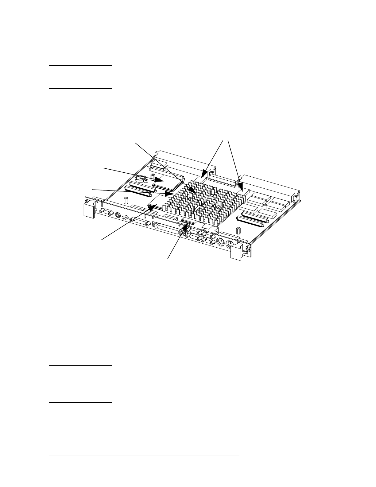
Model 743 VMEbus Board Computer
Top and Front View 2-3
Video Connector 2-6
Audio Connector 2-12
HP Parallel Connector 2-13
RS-232 Serial Connector 2-15
AUI LAN Connector 2-16
SCSI Connector 2-17
PS/2 Connector 2-19
Power Distribution Diagram 2-28
Model 743 LED Location 4-8
Model 743 Board Computer Exploded View 5-4
Captive Screws: Single and Dual Slot 743 5-9
Retaining Screws and Standoffs 5-14
GSC Fasteners 5-16
Extension Adapter Fasteners 5-18
Removing the Labels and Springs 5-20
Removing the Sleeves 5-21
Removing the PMC Expansion Adapter 5-22
Removing a PMC card from the Expansion Adapter 5-23
Removing the PMC Bridge Adapter 5-24
Removing a PMC card from the Bridge Adapter 5-25
HCRX Board Fasteners 5-27
Front Panel Extension Fasteners 5-28
Port Jack Screws 5-30
Removable ICs 5-32
xiv

Tables
Contents
Model 743 Power Requirements 1-6
Regulations 1-7
Environmental Requirements 1-7
LED Indicators 2-5
Video Connector Pins and Signals 2-6
Main Memory map 2-8
I/O Controller ASIC Memory Map 2-10
Audio Interface Specifications 2-12
Audio Connector Pinouts 2-12
HP Parallel Interface Specifications 2-13
HP Parallel Connector Pinouts 2-14
RS-232-C Specifications 2-14
RS-232-C Connector Pinouts 2-15
AUI LAN Connector Pinouts 2-16
SCSI Interface Specifications 2-17
SCSI Connector Pinouts 2-18
PS/2 Connector Pinouts 2-19
VME P1/J1 Pin Assignments & Signal Mnemonics 2-20
VME P2/J2 Pin Assignments & Signal Mnemonics 2-21
Supported Graphics Configurations 2-23
RAM Failure Chassis Codes vs. RAM Slot 2-24
Real-Time Clock Specifications 2-25
Interval Timer Specifications 2-26
Model 743 Board Computer Power Requirements 2-27
Main Menu Options 3-5
Paths for Booting and Human Interfaces 3-10
Mode Configuration - Control Flags 3-16
Interactive Tests 3-19
Firmware Information ROM Identification 3-22
Graphics Sub-System Combinations 3-29
LED Indicators 4-9
Interactive Tests 4-13
RAM Stack Cards 4-15
PIM Action Table 4-19
xv

Contents
Processor Module Error (Data Cache Parity) 4-22
Multi-Bit Memory Parity Error 4-23
Memory Address Ranges 4-24
Chassis Code Terms 4-26
Chassis Codes 4-27
Replaceable Parts 5-5
Reference Documentation 6-2
xvi

1
Product Information
1-1

Product Information
Product Description
Product Description
The HP 9000 Model 743 is a high-performance Precision Architecture board computer
based on the Hewlett-Packard PA-RISC 7100LC technology. It contains the follo wing ke y
features:
• Model type:
Model 743i/64
Model 743rt/64
Model 743i/100
Model 743rt/100
• VME slot configuration
Single slot
Dual slot (requires PCI Mezzanine Card (PMC) bridge board,
General System Connect (GSC) expansion kit or HCRX graphics board
Three slot (requires PMC bridge and expansion boards or GSC
expansion kit with ATM card)
• CPU PA-RISC PA7100-LC, processor performance
64 or 100 MHz
Cache - 256 KB
• Clocks
Battery-backed real-time clock
Interval timers (One 32 bit, Two 16 bit)
Watchdog timer
• Operating systems
HP-UX 9.05 (or later; some options require later releases). The
Model 743 typically boots from a hard disk drive. HP-UX may
also be installed from an external DDS or CD-ROM drive.
1-2

If the Model 743 is a client on a LAN, HP-UX can be booted
over the LAN.
HP-RT 2.0 and later.
• User interface
CDE or HP VUE graphical user interface (HP-UX only)
• Compatibility
Source and binary code compatible with Series 700 product
family.
• Monitors
Single or multiple display depending on number of installed
graphics options (onboard and/or external).
Product Information
Product Description
Color monitors:
HP A4490D, 17-inch, resolution 1280 x 1024
HP A4331D, 20-inch, resolution 1280 x 1024
Terminal (text only) connected to RS-232 port.
• Optional Graphics Capability
Graphics chip set providing onboard (including accelerated I/O)
graphics.
GSC expansion kit provides two slots for GSC HP A4267A
8-plane graphic cards.
HCRX8 or HCRX24 graphics boards allow the choice of one
HP A4267A graphics card in addition to the graphics board itself.
HP-RT supports an expansion kit with an HP A4267A graphics
card or an HCRX graphic board when on-board graphics is not
used.
1-3

Product Information
Product Description
NOTE: Either a GSC expansion kit or the HCRX expansion graphics
boards extend graphics capability beyond the onboard graphics
chip set of a Model 743 board computer. However, the HP-RT
operating system supports only one graphics display, and HP-UX
10.x supports up to three graphics displays.
• Main Memory
Single VME slot 743i: 16 to 128 MB RAM
Single VME slot 743rt: 8 to 128 MB RAM
Dual VME slot 743i: 16 to 256 MB RAM
Dual VME slot 743rt: 8 to 256 MB RAM
(Dual slot means an expansion kit or HCRX board must be
installed.)
NOTE: A Model 743 configured for more than two RAM cards (one in
each RAM stack) requires installation of an expansion kit or an
HCRX graphics board and occupies two VME slots.
Up to four RAM cards may be installed - three cards in RAM
stack 1, one card in RAM stack 2.
RAM cards may be placed in any order. A higher capacity memory card can be added on top of a lower capacity card or you can
reverse the order, with a lower capacity card on top of a higher
capacity card.
• Standard Features
Internal SCSI-2 single-ended bus
2 asynchronous RS-232-C ports (requires a conversion cable)
1 HP parallel port (requires a conversion cable)
1 LAN AUI port (requires a conversion cable)
2 mini-DIN PS/2 ports
1 slot for RAM memory (memory cards can be stacked)
CD-quality audio, supported only by HP-UX and requires a
conversion cable
PCMCIA adapter, supported only by HP-RT
• Dual Slot Upgrades
PMC bridge board (with two PMC sites, cannot be used w/
1-4

HCRX, and supported only on HP-UX)
GSC expansion kit (with two GSC sites)
HCRX8 graphics board (with one additional GSC site)
HCRX24 graphics board (with one additional GSC site)
GSC HP A4267A graphics card
FWD SCSI card
• 3-slot Upgrade
PMC expansion board (with two PMC sites, requires PMC
bridge)
ATM Network Card (up to 2, GSC expansion kit required, cannot be used with HCRX graphics)
• Other Supported Configurations
Product Information
Product Description
Hewlett Packard supports only products with HP approved
parts, accessories, peripherals, operating systems, and application programs.
1-5
Product Information
Technical Information
Technical Information
This section lists technical information for the Model 743. For official specifications, refer
to the HP 9000 Series 700i/rt Technical Data Sheet for Models 743i/rt and 748i VMEbus
Computer Systems.
Electrical
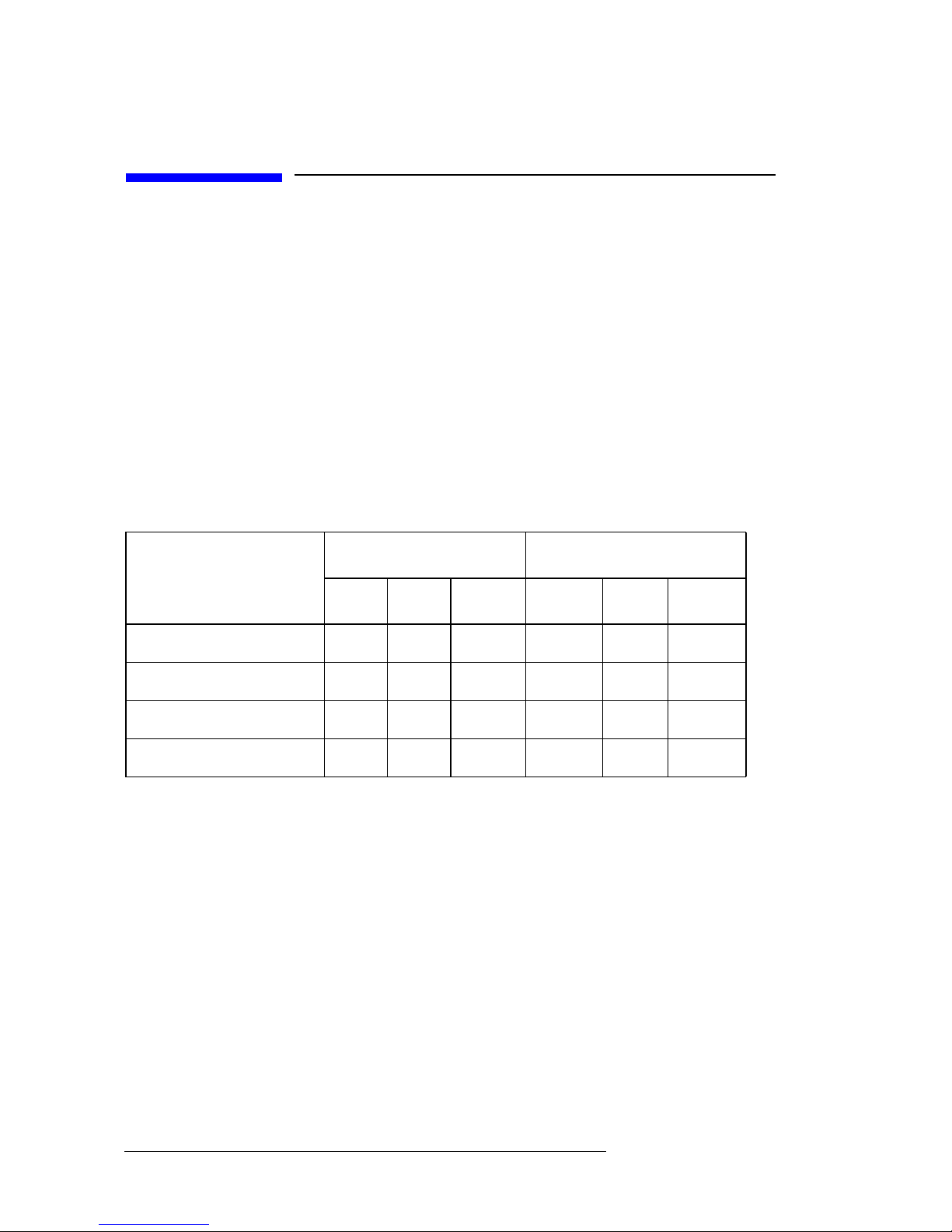
This section lists the electrical requirements for the Model 743. The following table shows
the power requirements for a 743 without on-board graphics.
Table 1-1 Model 743 Power Requirements
Model 743/64 Model 743/100
Assembly
+5 -12 +12 +5 -12 +12
System board
RAM Cards 0.2A 0 0 0.2A 0 0
On-board graphics 0.6A 0 0 0.75A 0 0
Graphics card, 8-bit 0.6A 0 0 0.75A 0 0
a
6.1A 0.1A 0.1A 7.5A 0.1A 0.1A
a. No on-board graphics, RAM, or accessory cards.
1-6
Product Information
Technical Information
Regulatory Compliances
The 743i and the 743rt comply with the regulations listed in Table 1-2.
Table 1-2 Regulations
Safety UL 1950, CSA22.2 950-M, EN60950
Electromagnetic
Certification
FCC 47 cfr. part 15 sub part J Class A; VCCI Class A;
EN55022/CISPR22 Class A; Australia C-Tick AS/NZS
2064.1/2:1992 and AS/NZS 3548:1995
Environmental Requirements
The following table shows the environmental requirements for the Model 743.
Table 1-3 Environmental Requirements
Temperature Operating: 0˚ to 55˚C;
10˚c/min rate of change maximum
Non-operating: -40˚ to 70˚C
Humidity Operating: 40˚C: 95% RH max
Altitude Operating: 4,600m (15,000 ft) to 40˚C
Non-operating: 15,300m (50,000 ft) to 70˚C
Air flow 150 linear feet per minute, 0˚ to 35˚C
200 linear feet per minute, 35˚ to 55˚C
1-7
Product Information
Technical Information
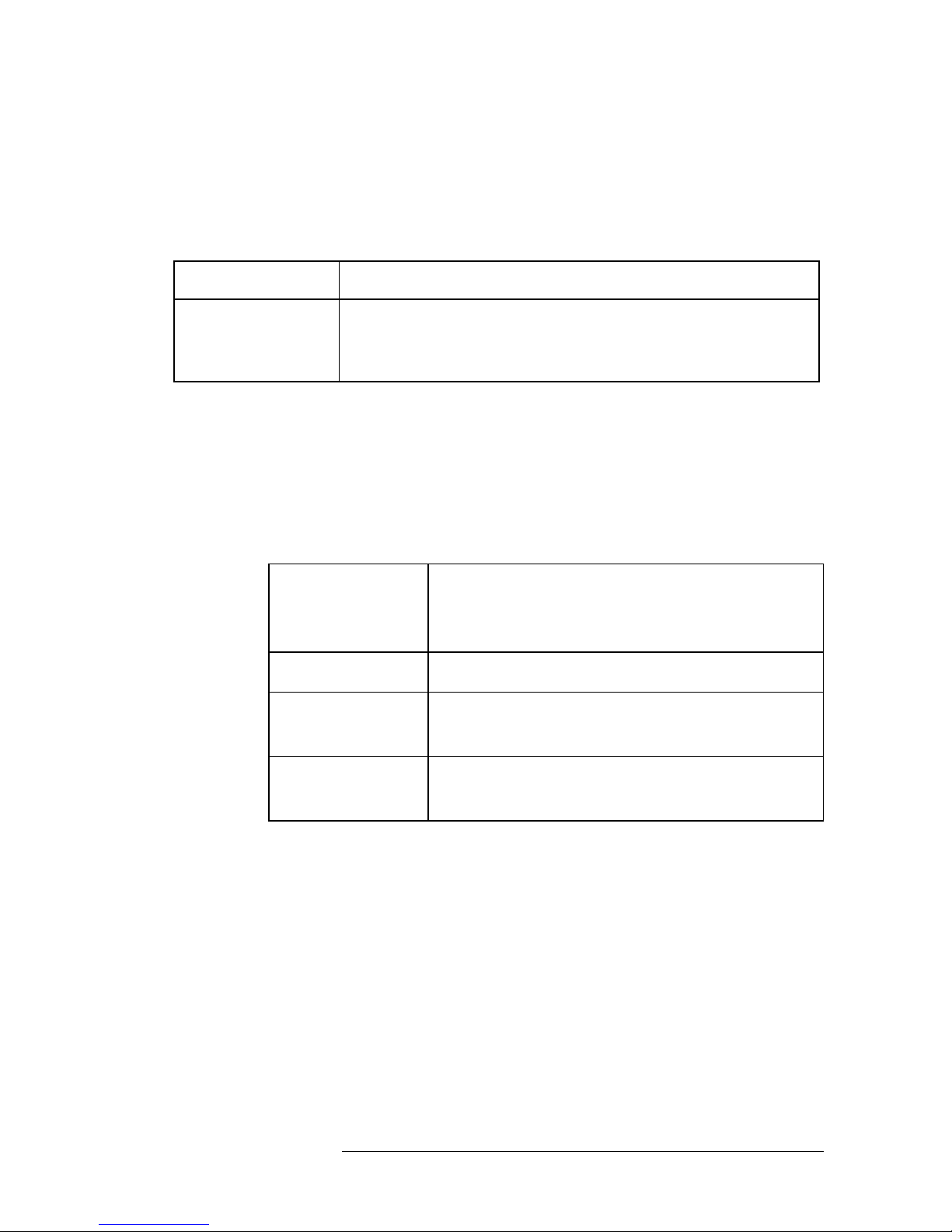
CAUTION: Integrated circuit case temperatures must not exceed
those shown in the following figure.
VME Controller 900C
ECL 95
0
C
I/O Controller 87
CPU 95
0
C
0
C
Graphics Controller 101
SRAM 1000C
0
C
Figure 1-1 Model 743 VMEbus Board Computer Temperatures
NOTE: The Model 743 should only be operated in an environment that is
free from conductive pollution, including dry non-conductive
pollution which could become conductive due to expected
condensation.
1-8

Product Information
Hardware Support
Hardware Support
This section provides information on the hardware support for the Model 743.
Field Repair Philosophy
If a problem or failure occurs with the Model 743, the problem is diagnosed to the assembly having the failed part. That assembly is then replaced. In some cases, an assembly may
be exchanged for rebuilt assembly. Other assemblies may only available as new. Refer to
Chapter 5 for information on replacement parts.
Additional Technical Information
Additional technical information on these products can be found in the HP 9000 Series
700i/rt Model 743i/rt and 748i VMEbus Computer Systems Technical Data Sheet.
Schematics
Hewlett-Packard support is limited to field-replaceable assemblies. Schematics are not
available for repair purposes to component level.
1-9

Product Information
Supported Products
Supported Products
Only products with Hewlett-Packard approved parts, accessories, peripherals, operating systems, and application programs are supported by
Hewlett-Packard. Any product with other than HP approved hardware or
software connected or installed must have the non-HP appro v ed hardware
and software removed by the customer before On-Site repair is conducted. The following lists describe the products supported by HP.
1-10

Product Information
Supported Products
Accessory Cards
The Model 743 supports the following accessory cards:
• Memory; one or more of these RAM cards supported on both HPUX and HP-RT operating systems:
HP A4263A 8 Mbyte RAM Card
HP A4264A 16 Mbyte RAM Card
HP A4265A 32 Mbyte RAM Card
HP A4266A 64 Mbyte RAM Card
• HP A4504A PMC Bridge Adapter - provides two sites for third party PMC cards (HP-UX only)
• HP A4509A PMC Expansion Adapter - provides two additional
sites for third party PMC cards (requires PMC Bridge Adapter - HPUX only)
• HP A4262A GSC Expansion Kit
• GSC Mezzanine cards:
HP A4267A 8-Plane Color Graphics Card
HP A4268A FWD SCSI
HP J3420A ATM (supported only by HP-UX)
• PCMCIA (supported only by HP-RT)
10-MB Flash disk card
20-MB Flash disk card
40-MB Flash disk card (HP-RT 3.0 and later - not available
from HP)
• Sub-Mezzanine Cards:
HCXR8 graphics card
HCRX24 graphics card
1-11

Product Information
Supported Products
Typical External Devices
The Model 743 supports the following external devices:
• LAN Transceiver:
HP A2670A ThinLAN Ethernet Transceiver
HP A2671A EtherTwist Transceiver.
• Speaker; 8 ohm impedance with1/8-inch sub-miniature stereo con-
nector (HP-UX only).
Cables
The Model 743 supports the following cables:
• Conversion cables:
HP A4300A HP Parallel; High-Density 25-Pin to
Standard 25-Pin F
HP A4301A RS-232; High-Density 9-Pin to Standard 9-Pin M
HP A4302A Audio; High-Density 9-Pin to Stereo Line-In
HP A4303A LAN; High-Density 15-Pin to 15-Pin AUI
HP A4304A Video; High-Density 15-Pin to Standard 15-Pin F
HP A4305A Video; High-Density 15-Pin to EVC connector
HP A4167A Video; Standard 15-Pin M to EVC connector (for
use with GSC graphics card and EVC monitor)
• Standard cables:
HP K2296 SCSI; High-Density 50-Pin to Standard Bail Lock
HP 92284A HP Parallel; 25-Pin M to 25-Pin M
HP 24542G RS-232 Terminal Cable; 9-Pin F to 25-Pin M
HP 24542H RS-232 Modem Cable; 9-Pin F to 25-Pin F
1-12

Keyboard and Mouse
The Model 743 supports the following:
• HP A2840A Keyboard with mini-DIN connector
• HP A2839A Mouse with mini-DIN connector
Product Information
Supported Products
1-13

Product Information
Repair Services
Repair Services
Hewlett-Packard supports three types of repair services:
• Return to Hewlett-Packard Repair - Customers can return the
product to their local HP Sales and Service Office. An HP Bench
Repair Engineer troubleshoots and repairs the hardware to the assembly level. The repair engineer may replace the defecti v e assembly with a new or rebuilt assembly. The product is then returned to
the customer . This service is av ailable through a service contract or
a time-and-materials basis.
• On-Site Repair - On-Site Repair is performed at the customer’s
site. This service is available through a service contract or a timeand-materials basis.
• Customer Repair - Customers have the option of repairing their
own HP products. Contact your nearest Hewlett-Packard Sales and
Service Office for information concerning service training, special
tools, test equipment, and spare parts.
1-14
 Loading...