

HP 9000 360, 9000 370 Service Handbook
Service Handbook
UP 9000 Series 300 Computers
Models
360/370
HP
Part
Number
98579-90039
Flin-
HEWLETT
a:~
PACKARD
Hewlett-Packard Company
3404 East Harmony Road, Fort Collins, Colorado 80525
NOTICE
The information contained
in
this document is subject to change without notice.
HEWLETT-PACKARD MAKES
NO WARRANTY
OF
ANY KIND WITH REGARD TO THIS MANUAL. INCLUDING.
BUT NOT LIMITED TO. THE IMPLIED WARRANTIES OF MERCHANTABILITY AND FITNESS
FOR
A PARTIC-
ULAR PURPOSE. Hewlett-Packard shall not
be
liable for errors contained herein or direct. indirect. special.
incidental
or
consequential damages
in
connection with the furnishing. performance. or use
of
this material.
WARRANTY
A copy
of
the specific warranty terms applicable to your Hewlett-Packard product and replacement parts can
be
obtained from your local Sales and Service Office.
Copyright
© Hewlett-Packard Company 1988
ThiS
document contains information which is protected by copynght.
All
rights are reserved. Reproduction adaptatIOn.
or translation without prior written premission is prohibited. except as allowed under the copyright laws
Restricted Rights Legend
Use.
duplication or disclosure by the U.S. Government Department
of
Defense is subject to restrictions
as
set forth
In
paragraph (b)(3)(ii)
of
the Rights in Technical Data and Software clause
in
FAR
52.227-7013.
Copyright
© AT&T. Inc. 1980. 1984
Copyright
© The Regents
of
the University
of
California
1979.1980.1983
This software and documentation is based
in
part on the Fourth Berkeley Software Distribution under license from the
Regents
of
the University of CaHfomia.
ii
Printing History
New editions of this manual will incorporate all material
updated
since
the
previous edition.
Update
packages may be issued between editions
and
contain replacement
and
additional pages
to
be
merged into
the
manual by the user. Each
updated
page will
be
indicated by a revision
date
at
the
bottom
of the page. A vertical
bar
in
the
margin indicates
the
changes on each page. Note
that
pages which are rearranged due
to
changes on a previous page are
not
considered revised.
The
manual printing
date
and
part
number indicate its
current
edition.
The
printing
date
changes when a new edition
is
printed. (Minor
corrections
and
updates which are incorporated
at
reprint do
not
cause
the
date
to
change.)
The
manual
part
number changes when extensive
technical changes are incorporated.
June
1988 ... Edition 1
Printing
History iii
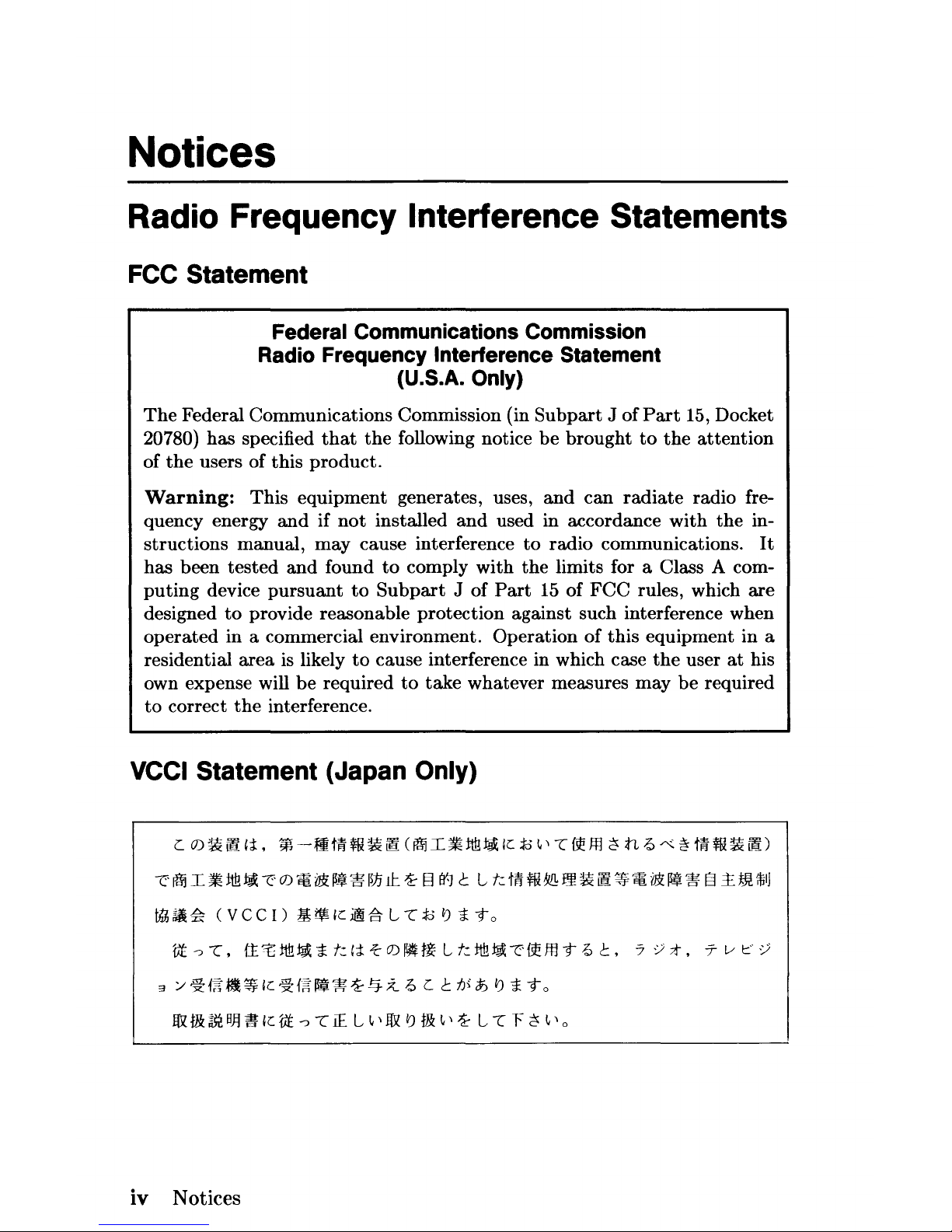
Notices
Radio Frequency Interference Statements
FCC Statement
Federal Communications Commission
Radio Frequency Interference Statement
(U.S.A. Only)
The
Federal Communications Commission (in
Subpart
J of
Part
15, Docket
20780)
has
specified
that
the
following notice
be
brought
to
the
attention
of
the
users of this
product.
Warning:
This
equipment generates, uses,
and
can
radiate
radio fre-
quency energy
and
if
not
installed
and
used in accordance
with
the
in-
structions
manual,
may
cause interference
to
radio communications.
It
has
been
tested
and
found
to
comply
with
the
limits for a Class A com-
puting
device
pursuant
to
Subpart J of
Part
15
of
FCC
rules, which
are
designed
to
provide reasonable
protection
against such interference when
operated
in
a commercial environment. Operation
of
this
equipment in a
residential
area
is likely
to
cause interference in which case
the
user
at
his
own expense will
be
required
to
take
whatever measures
may
be
required
to
correct
the
interference.
VCCI Statement (Japan Only)
~fiI.~~~0.~.W~±~§~tLkmw~eH.~.~.~§~m~
thh~~
(VCC!)
£~Ii::ilg.LL;JQl)i-to
1lt
-:J
L,
f:t
t
~
~
i
t:
Ii
i-
01~H~
L
t:
~ ~
~ ~
ffl
-t
6
t.
7:);t.
T v
f='
:)
3
/'
~f~~~Jde
~f~.~
~.q.:z
6 c t
tJi
~
I) i
-to
1&
t&
m
BjJ ~ Ie
1lt
-:J
L
1£
L ~ ,
1&
I)
t&
~
,~
L L F
~
~'o
iv
Notices
Manufacturer'S Declaration (Germany Only)
Herstellerbescheinigung
Hiermit wird bescheinigt,
daB
dieses Gerat in Ubereinstimmung mit
den Bestimmungen der Postverfiigung
1046/84 funkentstort ist. Der
Deutschen Bundespost wurde das Inverkehrbringen dieses Gerates
angezeigt und die Berechtigung zur Uberpriifung der
Serie auf Ein-
haltung der Bestimmungen eingeraumt.
Safety Considerations
WARNINGs, CAUTIONs, and Notes
Warnings, cautions and notes are used throughout this document
to
alert the user to conditions of importance. They are used as follows:
• WARNINGS contain information which, if not observed, could
result in injury to personnel or loss of life.
• CAUTIONS contain information which, if not observed, could
result in damage to or destruction of equipment.
• Notes contain information
that
will assist you in accomplishing
the
job.
Notices v
Examples:
WARNING
The power supply presents a hazard to personnel.
Extreme care must be taken when connecting
voltmeter probes to the test points. De-energize
the product
by
turning
it
off and removing its
power cord before connecting or removing test
probes.
I CAUTION I
The
printed
circuit assemblies in this
product
are susceptible
to
damage by electro-static dis-
charge.
Extreme
care
must
be taken when han-
dling
printed
circuit assemblies. Use
an
Anti-
static
Workstation while handling printed circuit
assemblies.
Note
Hewlett-Packard
supports
repair of this
product
only
to
the
assembly level.
The
fault
is
diagnosed
to
the
assembly
that
is
causing
the
problem.
That
assembly
is
then
replaced with a new
or
rebuilt
one.
vi
Notices
Information Locator
Finding Service Information
On
the
next page
is
a Service Infonnation Locator.
It
shows where to
find a variety of subjects dealing with servicing these products. To use
this table, first find the type of information you need
to
reference in
the
left-hand column. Next, move
to
the
right in
that
row
to
a referenced
chapter number. Last, move
up
the
column with
the
information's
referenced chapter to
the
top. Across
the
top are manual titles
and
part
numbers
that
have
the
information documented.
Chapter identifiers in
the
Locator use
the
following codes:
Chapter
Number: Numbers, such as
2.
Inclusive chapters, such as 4-6.
Appendices: Letters, such as A for Appendix
A.
Entire Manual: All
Varies:
* (Check Table of Contents or Index.)
In some cases, two
or
more references will be shown for a given infonna-
tion type. You should check all references
to
be sure you get
the
specific
information you need.
For example, suppose you need
to
find
out
what
the
Repair Philosophy
is
fo
the
HP
98570A Bus Expander. Locating "Repair Philosophy" in
the
left-hand column,
and
moving
to
the
right in
that
row, you'll notice
that
this information
is
in
"Chapter
1"
of a manual.
At
the
top
of this
column
is
the
manual's abbreviated title.
Chapter
7 in this manual lists
manual titles
and
part
numbers for service information.
Information Locator
vii
Service Information Locator
Manuals identified in this locator are abbreviated by their initials:
81M
Service Information Manual
IRM
Installation Reference Manual
8HB
Service Handbook
PIN
Product
Installation Note
CRM
Configuration Reference Manual
TD8
Technical
Data
Sheet/Price List
TTM
Series 300 Test Tools Manual
ADG
Accessory Development Guide
8PM
Site Preparation Manual
viii Information Locator
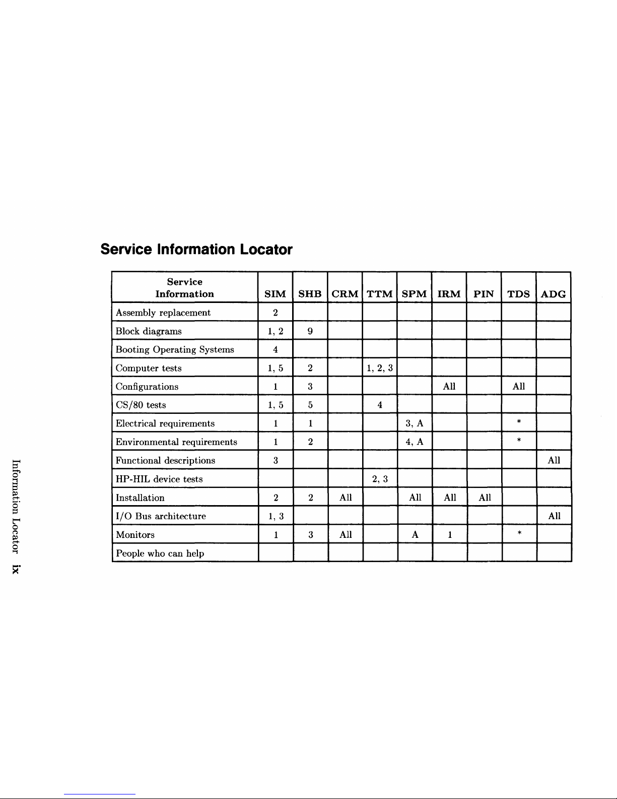
Service
Information
Locator
Service
Information
SIM
SHB
CRM
TTM
SPM
IRM
PIN
TDS
ADG
Assembly replacement
2
Block diagrams
1,2
9
Booting
Operating
Systems 4
Computer
tests
1,5
2
1,2,3
Configurations 1 3
All
All
CS/80
tests
1,5
5
4
Electrical requirements
1
1
3, A
*
Environmental requirements
1
2
4, A
*
Functional descriptions
3
All
HP -HIL
device
tests
2,
3
Installation 2
2
All
All
All All
I/O
Bus architecture
1,3
All
Monitors
1 3
All
A 1
*
People who
can
help
><0
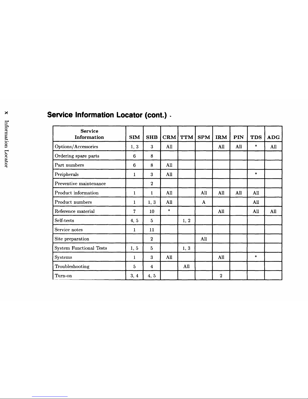
Service
Information
Locator
(cont.) .
Service
Information
SIM
SHB
CRM
TTM
SPM
IRM
PIN
TDS
ADG
Options/
Accessories
1,3
3
All
All All
*
All
Ordering spare
parts
6 8
Part
numbers
6
8
All
Peripherals
1
3
All
*
Preventive maintenance
2
Product
information
1
1 All All
All All All
Product
numbers
1
1,3
All A All
Reference
material
7
10
*
All
All
All
Self-tests
4,
5
5
1,2
Service notes
1
11
Site
preparation
2
All
System Functional Tests
1,5
5
1,3
Systems
1 3
All
All
*
Troubleshooting
5
4
All
Turn-on
3,4
4, 5
2
--
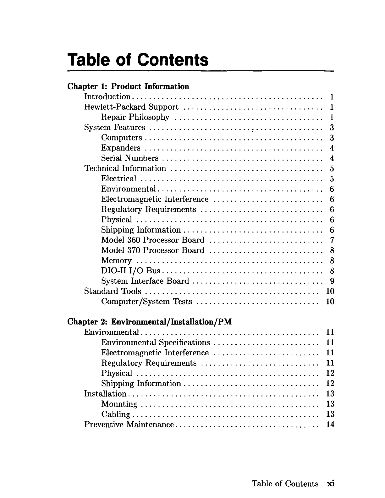
Table of Contents
Chapter
1:
Product Information
Introduction. . . . . . . . . . . . . . . . . . . . . . . . . . . . . . . . . . . . . . . . . . .
..
1
Hewlett-Packard Support
.................................
1
Repair Philosophy
...................................
1
System Features
........................
~
. . . . . . . . . . . . . .
..
3
Computers
........................................
" 3
Expanders
..........................................
4
Serial Numbers . . . . . . . . . . . . . . . . . . . . . . . . . . . . . . . . . . . .
..
4
Technical Information
....................................
5
Electrical
...........................................
5
Environmental. . . . . . . . . . . . . . . . . . . . . . . . . . . . . . . . . . . . .
..
6
Electromagnetic Interference
..........................
6
Regulatory Requirements
.............................
6
Physical.
. . . . . . . . . . . . . . . . . . . . . . . . . . . . . . . . . . . . . . . . .
..
6
Shipping Information. . . . . . . . . . . . . . . . . . . . . . . . . . . . . . .
..
6
Model
360 Processor Board
...........................
7
Model
370 Processor Board
...........................
8
Memory
............................................
8
DIO-II
I/O
Bus.
. . . . . . . . . . . . . . . . . . . . . . . . . . . . . . . . . . .
..
8
System Interface Board . . . . . . . . . . . . . . . . . . . . . . . . . . . . .
..
9
Standard
Tools.
. . . . . . . . . . . . . . . . . . . . . . . . . . . . . . . . . . . . . .
..
10
Computer /System Tests
.............................
10
Chapter
2:
Environmental/Installation/PM
Environmental
........................................
"
11
Environmental Specifications . . . . . . . . . . . . . . . . . . . . . . .
..
11
Electromagnetic Interference
.........................
11
Regulatory Requirements
............................
11
Physical.
. . . . . . . . . . . . . . . . . . . . . . . . . . . . . . . . . . . . . . . .
..
12
Shipping Information. . . . . . . . . . . . . . . . . . . . . . . . . . . . . .
..
12
Installation. . . . . . . . . . . . . . . . . . . . . . . . . . . . . . . . . . . . . . . . . . .
..
13
Mounting . . . . . . . . . . . . . . . . . . . . . . . . . . . . . . . . . . . . . . . .
..
13
Cabling
................
, . . .
.. ..
. .
......
. . . .
..
......
13
Preventive Maintenance. . . . . . . . . . . . . . . . . . . . . . . . . . . . . . . .
..
14
Table of Contents
xi
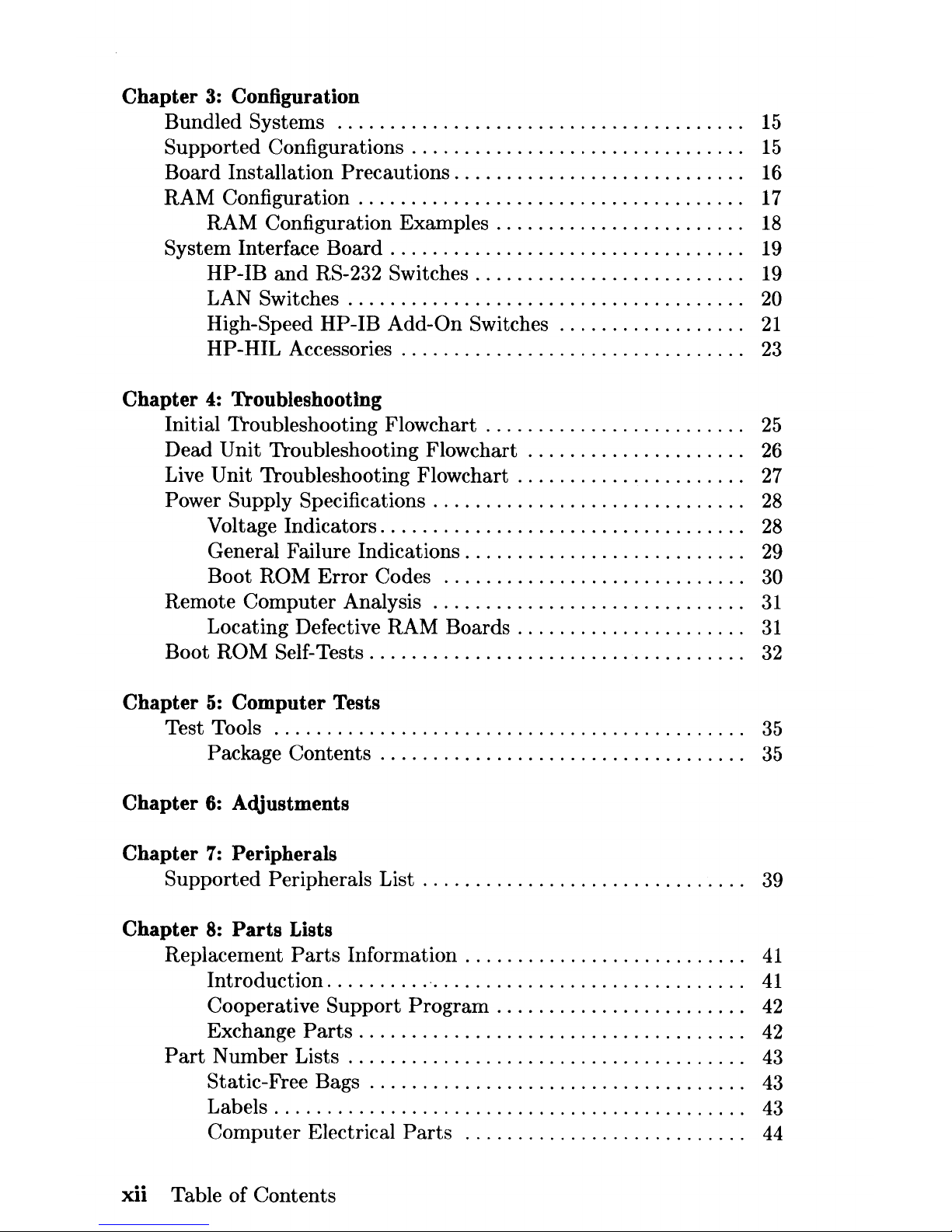
Chapter
3: Configuration
Bundled Systems
.......................................
15
Supported Configurations . . . . . . . . . . . . . . . . . . . . . . . . . . . . . .
..
15
Board Installation
Precautions.
. . . . . . . . . . . . . . . . . . . . . . . . .
..
16
RAM Configuration . . . . . . . . . . . . . . . . . . . . . . . . . . . . . . . . . . .
..
17
RAM Configuration Examples . . . . . . . . . . . . . . . . . . . . . .
..
18
System Interface Board . . . . . . . . . . . . . . . . . . . . . . . . . . . . . . . .
..
19
HP-IB
and
RS-232 Switches. . . . . . . . . . . . . . . . . . . . . . . .
..
19
LAN Switches
......................................
20
High-Speed HP-IB Add-On Switches
..................
21
HP-HIL Accessories. . . . . . . . . . . . . . . . . . . . . . . . . . . . . . .
..
23
Chapter
4:
Troubleshooting
Initial Troubleshooting Flowchart . . . . . . . . . . . . . . . . . . . . . . .
..
25
Dead Unit Troubleshooting
Flowchart.
. . . . . . . . . . . . . . . . . .
..
26
Live Unit Troubleshooting
Flowchart.
. . . . . . . . . . . . . . . . . . .
..
27
Power Supply Specifications
.............................
,
28
Voltage Indicators. . . . . . . . . . . . . . . . . . . . . . . . . . . . . . . . .
..
28
General Failure Indications. . . . . . . . . . . . . . . . . . . . . . . . .
..
29
Boot ROM
Error
Codes
.............................
30
Remote Computer Analysis
..
'"
.........................
31
Locating Defective RAM
Boards.
. . . . . . . . . . . . . . . . . . .
..
31
Boot ROM Self-Tests. . . . . . . . . . . . . . . . . . . . . . . . . . . . . . . . . .
..
32
Chapter
5:
Computer
Tests
Test Tools
.............................................
35
Package Contents . . . . . . . . . . . . . . . . . . . . . . . . . . . . . . . . .
..
35
Chapter
6:
Adjustments
Chapter
7:
Peripherals
Supported Peripherals List . . . . . . . . . . . . . . . . . . . . . . . . . . . . .
..
39
Chapter
8:
Parts
Lists
Replacement
Parts
Information.
. . . . . . . . . . . . . . . . . . . . . . . .
..
41
Introduction. . . . . . . . .
..
. . . . . . . . . . . . . . . . . . . . . . . . . . .
..
41
Cooperative
Support
Program
. . . . . . . . . . . . . . . . . . . . . .
..
42
Exchange
Parts.
. . . . . . . . . . . . . . . . . . . . . . . . . . . . . . . . . .
..
42
Part
Number
Lists.
. . . . . . . . . . . . . . . . . . . . . . . . . . . . . . . . . . .
..
43
Static-Free Bags . . . . . . . . . . . . . . . . . . . . . . . . . . . . . . . . . .
..
43
Labels
.............................................
43
Computer Electrical
Parts
...........................
44
xii
Table of Contents
Computer Case
Parts.
. . . . . . . . . . . . . . . . . . . . . . . . . . . . .
..
46
Expander
Case
Parts
Diagram.
. . . . . . . . . . . . . . . . . . . . .
..
48
HP
98570A
and
98568A Opt. 132 Expander
............
49
Printed Circuit Boards
..............................
50
Miscellaneous Electrical
Parts
........................
51
External Cables. . . . . . . . . . . . . . . . . . . . . . . . . . . . . . . . . . .
..
51
HP-HIL
Devices.
. . . . . . . . . . . . . . . . . . . . . . . . . . . . . . . . .
..
52
Chapter
9:
Diagrams
Model
360/370 Computer
................................
53
Computer Block Diagram . . . . . . . . . . . . . . . . . . . . . . . . . .
..
53
Power Supply
......................................
54
Power Distribution . . . . . . . . . . . . . . . . . . . . . . . . . . . . . . . .
..
55
Model 360 Processor
Board.
. . . . . . . . . . . . . . . . . . . . . . .
..
56
Model
370 Processor Board
........................
" 57
RAM Boards . . . . . . . . . . . . . . . . . . . . . . . . . . . . . . . . . . . . .
..
58
System Interface Board . . . . . . . . . . . . . . . . . . . . . . . . . . . .
..
59
Video Boards. . . . . . . . . . . . . . . . . . . . . . . . . . . . . . . . . . . . .
..
60
Chapter
10: References
Related Hardware Documentation. . . . . . . . . . . . . . . . . . . . . . .
..
61
Hardware Support Documentation
....................
61
Installation Manuals/Notes. . . . . . . . . . . . . . . . . . . . . . . . .
..
63
Chapter
11: Service
Notes.
. . . . . . . . . . . . . . . . . . . . . . . . . . . . . . . .
..
65
Table of Contents xiii

xiv Table of Contents
Product Information
1
Introduction
Information in this handbook refers
to
the
HP 9000 Series 300 110del 360
and
370 computers. These computers are
product
numbers
HP
98579A
and
HP 98579B, respectively.
Where applicable,
the
information also applies
to
the
HP
98568A
Opt.
132
and
HP 98570A Direct-'Connect
System/DIO
Slot Expanders.
Hewlett-Packard Support
Support services
and
policies mentioned in this section are subject
to
change. Please consult your local Hewlett-Packard Sales
and
Service
Office for the current
support
policies.
Repair Philosophy
Field Repair Philosophy for
the
Model 360/370 Computers
and
the
HP
98568A Opt. 132
and
98570A Expanders
is
assembly,
or
board
level.
This means
that
when a failure occurs,
the
problem is diagnosed
to
the
assembly having
the
failed
part.
That
assembly
is
then
replaced.
Replacement assemblies are available through local
HP
Sales
and
Service
Offices.
Some assemblies may be exchanged for rebuilt ones.
Other
assemblies
are only available as new ones. Refer
to
Chapter
6,
or
the
Service
Handbook,
Chapter
8, for information on replacement parts.
Product
Information 1

Schematics
In
support of
the
repair philosophy, this manual contains information
to
the
assembly level. Schematics are
not
available for these products.
Supported Configurations
Only computer systems with Hewlett-Packard approved parts, accessories, peripherals, operating systems
and
application programs are sup-
ported
by Hewlett-Packard. Any computer system with other
than
HP
approved hardware
or
software connected or installed must have the
non-
HP
approved hardware
and
software removed by
the
customer be-
fore
On-Site
or
Service Center repair
is
accomplished.
Refer
to
the
Series 300 Configuration Reference Manual (98561-90020)
for supported hardware/software products
and
combinations thereof.
2
Product
Information
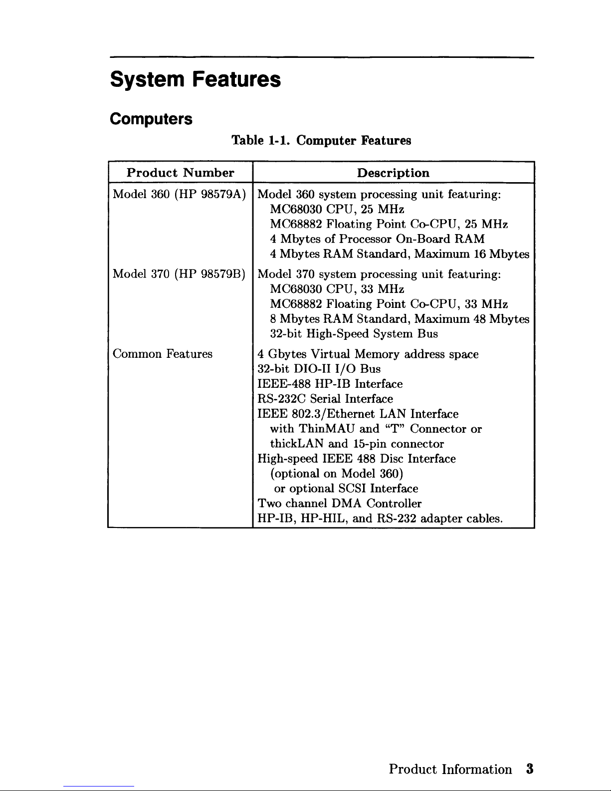
System Features
Computers
Table 1-1. Computer Features
Product
Number
Description
Model 360
(HP
98579A) Model 360
system
processing
unit
featuring:
MC68030
CPU,
25 MHz
MC68882
Floating
Point
Co-CPU,
25 MHz
4 Mbytes
of
Processor
On-Board
RAM
4 Mbytes
RAM
Standard,
Maximum
16 Mbytes
Model
370
(HP
98579B)
Model
370 system processing
unit
featuring:
MC68030
CPU,
33 MHz
MC68882
Floating
Point
Co-CPU, 33 MHz
8 Mbytes RAM
Standard,
Maximum
48 Mbytes
32-bit High-Speed System Bus
Common Features
4 Gbytes
Virtual
Memory address space
32-bit
DIO-II
I/O
Bus
IEEE-488
HP
-IB Interface
RS-232C Serial Interface
IEEE
802.3/Ethernet
LAN Interface
with
ThinMA U and
"T" Connector
or
thickLAN
and
15-pin connector
High-speed
IEEE
488 Disc Interface
(optional on Model
360)
or
optional SCSI Interface
Two channel D MA Controller
HP-IB,
HP-HIL,
and
RS-232
adapter
cables.
Product Information 3
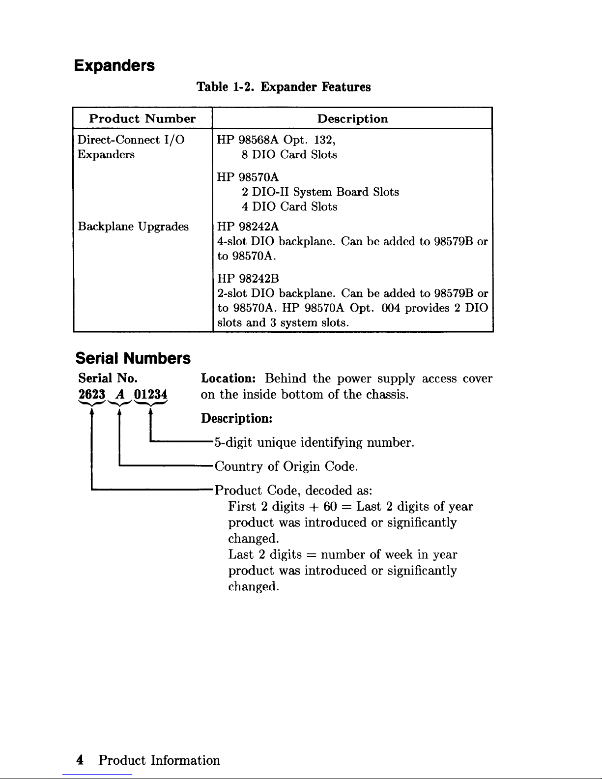
Expanders
Product
Number
Direct-Connect
I/O
Expanders
Backplane Upgrades
Serial Numbers
Serial No.
2623 A 01234
~'-....-"~
Table 1-2. Expander Features
Description
HP
98568A
Opt.
132,
8
DIO
Card
Slots
HP
98570A
2 DIO-II System
Board
Slots
4 D I
0
Card
Slots
HP
98242A
4-slot
DIO
backplane.
Can
be
added
to
98579B
or
to
98570A.
HP
98242B
2-slot
DIO
backplane.
Can
be
added
to
98579B
or
to
98570A.
HP
98570A
Opt.
004 provides 2 DIO
slots
and 3 system
slots.
Location: Behind the power supply access cover
on
the
inside
bottom
of
the
chassis.
1 t Description:
5-digit unique identifying number.
Country
of Origin Code.
~-------Product
Code, decoded as:
4
Product
Information
First
2 digits + 60 = Last 2 digits of year
product
was introduced
or
significantly
changed.
Last 2 digits = number of week in year
product
was introduced
or
significantly
changed.
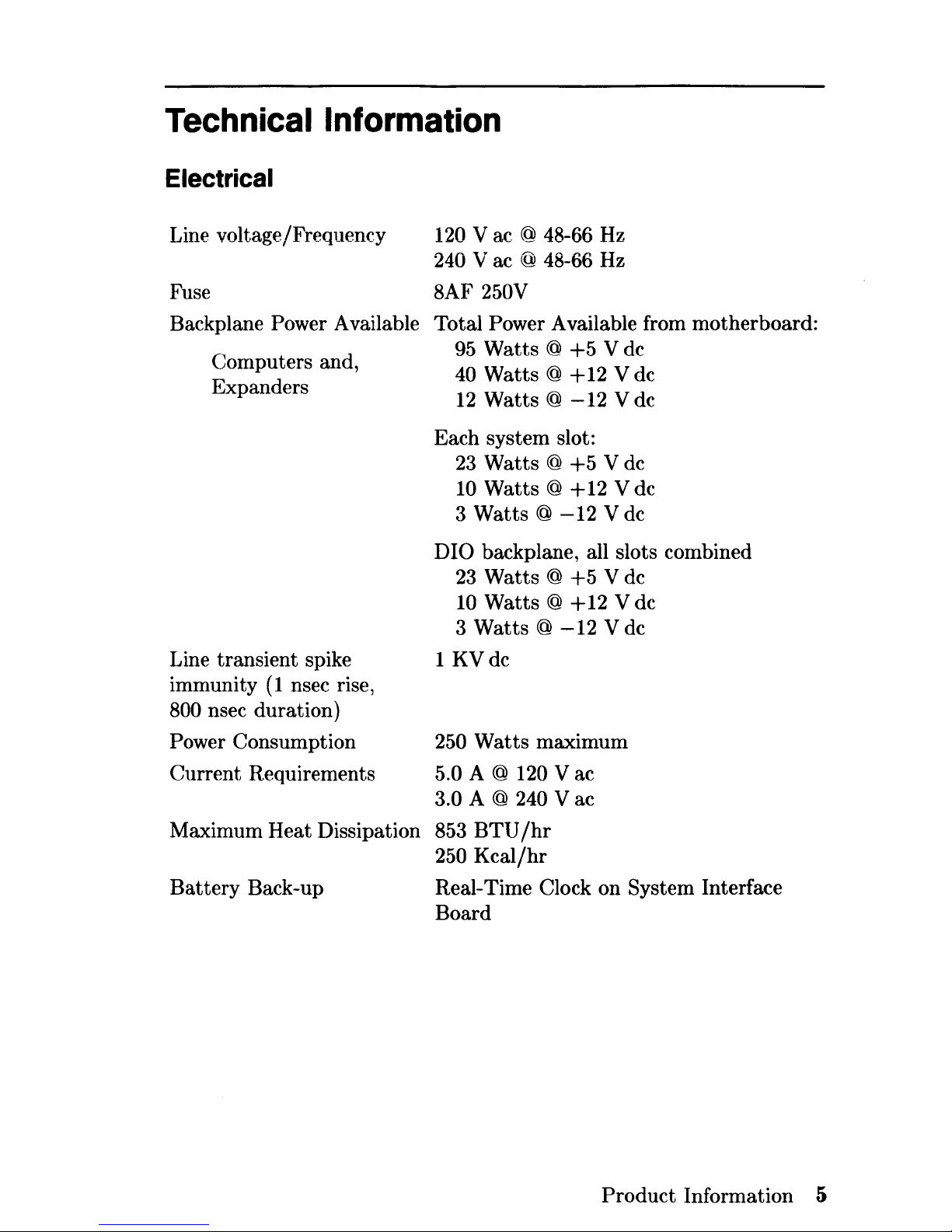
Technical
Information
Electrical
Line voltage/Frequency
120
Vac
@ 48-66 Hz
240 V ac @ 48-66 Hz
Fuse 8AF
250V
Backplane Power Available Total Power Available from motherboard:
Computers and,
Expanders
Line transient spike
immunity
(1
nsec rise,
800 nsec duration)
Power Consumption
Current Requirements
Maximum Heat Dissipation
Battery
Back-up
95
Watts @
+5
V de
40
Watts @
+12
V dc
12
Watts @
-12
V dc
Each system slot:
23
Watts @ +5
V dc
10
Watts @ +12
V dc
3
Watts @ -12
V dc
DIO backplane, all slots combined
23
Watts @
+5
V de
10
Watts @ +12
V dc
3
Watts @ -12
V dc
1
KVdc
250
Watts
maximum
5.0 A @ 120 V ac
3.0 A @ 240 V ac
853
BTU/hr
250
Kcal/hr
Real-Time Clock on System Interface
Board
Product
Information 5
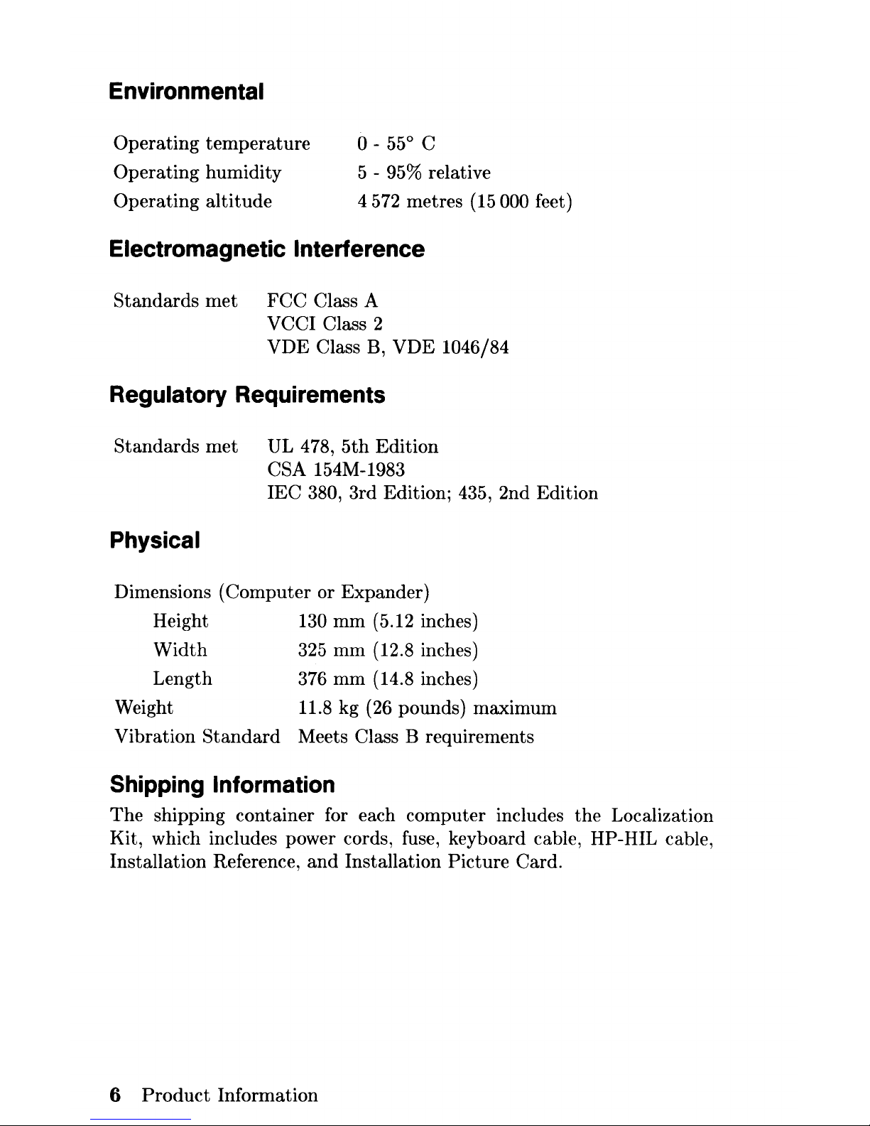
Environmental
Operating
temperature
Operating humidity
Operating altitude
0-
55° C
5 - 95% relative
4
572
metres (15 000 feet)
Electromagnetic Interference
Standards
met
FCC
Class A
VCCI Class 2
VDE
Class B, VDE 1046/84
Regulatory Requirements
Standards
met
UL 478,
5th
Edition
CSA 154M-1983
IEC
380, 3rd Edition; 435, 2nd Edition
Physical
Dimensions (Computer or Expander)
Height
130
mm
(5.12 inches)
Width
325
mm
(12.8 inches)
Length
Weight
376
mm
(14.8 inches)
11.8 kg (26 pounds) maximum
Vibration
Standard
Meets Class B requirements
Shipping Information
The
shipping container for each computer includes
the
Localization
Kit, which includes power cords, fuse, keyboard cable, HP-HIL cable,
Installation Reference,
and
Installation Picture Card.
6
Product
Information
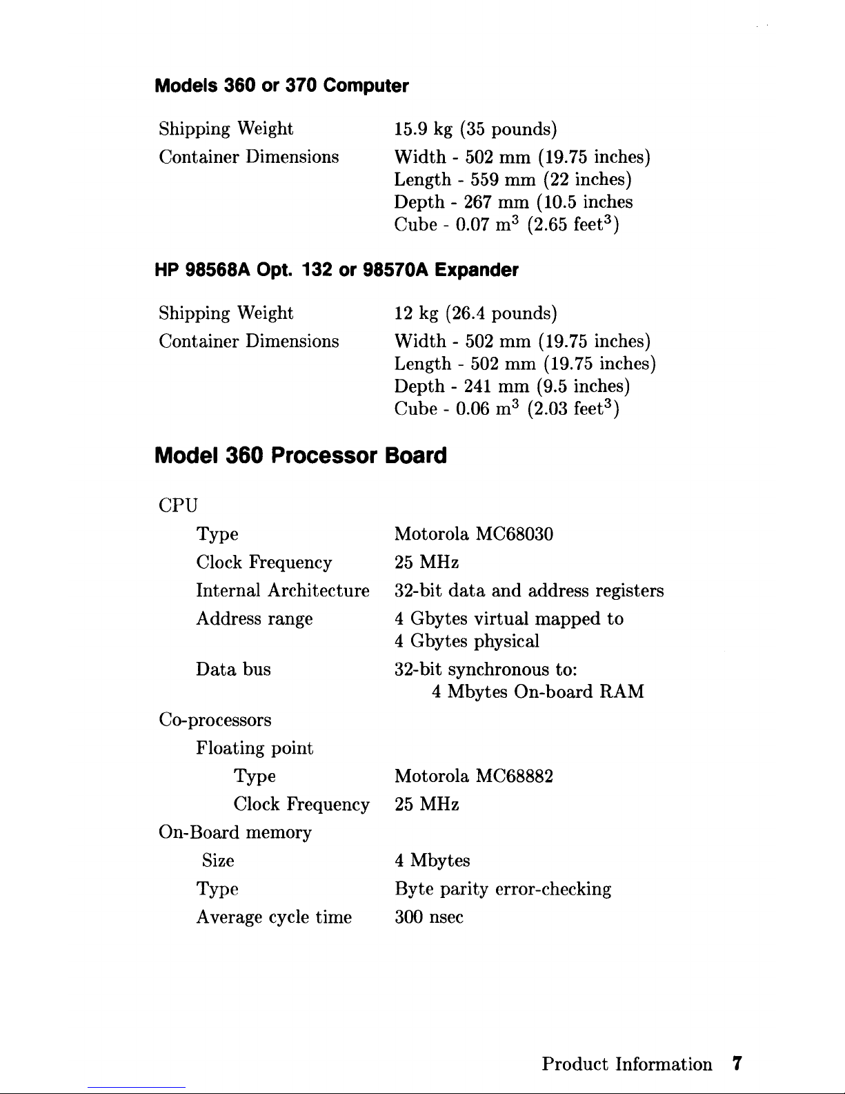
Models 360 or 370 Computer
Shipping Weight
Container Dimensions
15.9 kg (35 pounds)
Width -502
mm
(19.75 inches)
Length - 559
mm
(22 inches)
Depth
- 267
mm
(10.5 inches
Cube -
0.07 m3 (2.65 feet
3
)
HP
98568A Opt. 132 or 98570A Expander
Shipping Weight
Container Dimensions
12
kg (26.4 pounds)
Width
- 502
mm
(19.75 inches)
Length -
502
mm
(19.75 inches)
Depth -241
mm
(9.5 inches)
Cube -
0.06 m3 (2.03 feet
3
)
Model 360 Processor Board
CPU
Type
Clock Frequency
Internal Architecture
Address range
Data
bus
Co-processors
Floating point
Type
Clock Frequency
On-Board memory
Size
Type
Average cycle time
Motorola
MC68030
25
MHz
32-bit
data
and
address registers
4 Gbytes virtual
mapped
to
4 Gbytes physical
32-bit synchronous to:
4 Mbytes
On-board RAM
Motorola MC68882
25
MHz
4 Mbytes
Byte parity error-checking
300 nsec
Product
Information 7
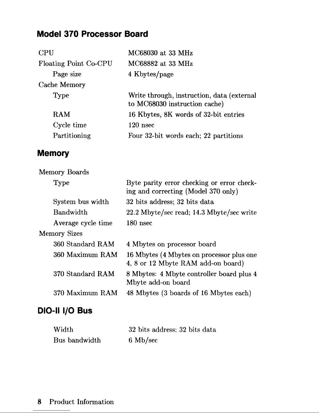
Model 370 Processor Board
CPU
Floating
Point
Co-CPU
Page size
Cache Memory
Type
RAM
Cycle time
Partitioning
Memory
Memory Boards
Type
System bus
width
Bandwidth
Average cycle time
Memory Sizes
360
Standard
RAM
360 Maximum RAM
370
Standard
RAM
370 Maximum RAM
010-11
I/O Bus
Width
Bus
bandwidth
8
Product
Information
MC68030
at
33 MHz
MC68882
at
33
MHz
4
Kbytes/page
Write through, instruction,
data
(external
to
M C68030 instruction cache)
16 Kbytes, 8K words of 32-bit entries
120 nsec
Four 32-bit words each;
22
partitions
Byte
parity
error checking
or
error check-
ing
and
correcting (Model 370 only)
32
bits
address;
32
bits
data
22.2 Mbyte/sec read; 14.3 Mbyte/sec write
180 nsec
4 Mbytes on processor
board
16 Mbytes
(4
Mbytes on processor plus one
4,8
or
12
Mbyte RAM add-on board)
8 Mbytes: 4 Mbyte controller
board
plus 4
Mbyte add-on
board
48
Mbytes
(3
boards of
16
Mbytes each)
32
bits
address;
32
bits
data
6
Mb/sec
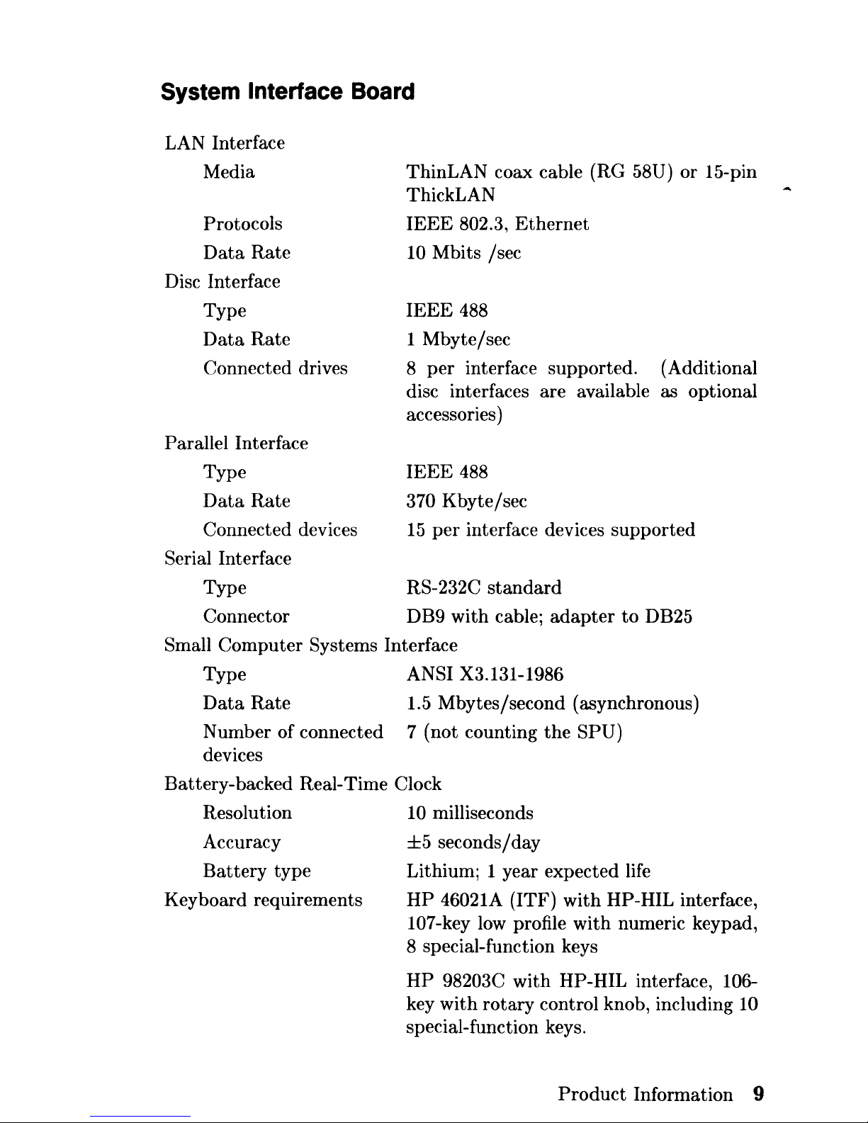
System Interface Board
LAN Interface
Media
Protocols
Data
Rate
Disc Interface
Type
Data
Rate
Connected drives
Parallel Interface
Type
Data
Rate
Connected devices
Serial Interface
Type
Connector
ThinLAN coax cable (RG 58U) or 15-pin
ThickLAN
IEEE
802.3,
Ethernet
10
Mbits /sec
IEEE
488
1 Mbyte/sec
8
per
interface supported. (Additional
disc interfaces are available as optional
accessories)
IEEE
488
370 Kbyte/sec
15
per
interface devices supported
RS-232C
standard
DB9 with cable;
adapter
to
DB25
Small Computer Systems Interface
Type
ANSI X3.131-1986
Data
Rate
1.5 Mbytes/second (asynchronous)
Number of connected 7 (not counting
the
SPU)
devices
Battery-backed Real-Time
Clock
Resolution
Accuracy
Battery
type
Keyboard requirements
10
milliseconds
±5
seconds/day
Lithium; 1 year expected life
HP
46021A (ITF)
with
HP-HIL interface,
107-key
low
profile
with
numeric keypad,
8 special-function keys
HP
98203C
with
HP-HIL interface, 106-
key
with
rotary
control knob, including 10
special-function keys.
Product
Information 9
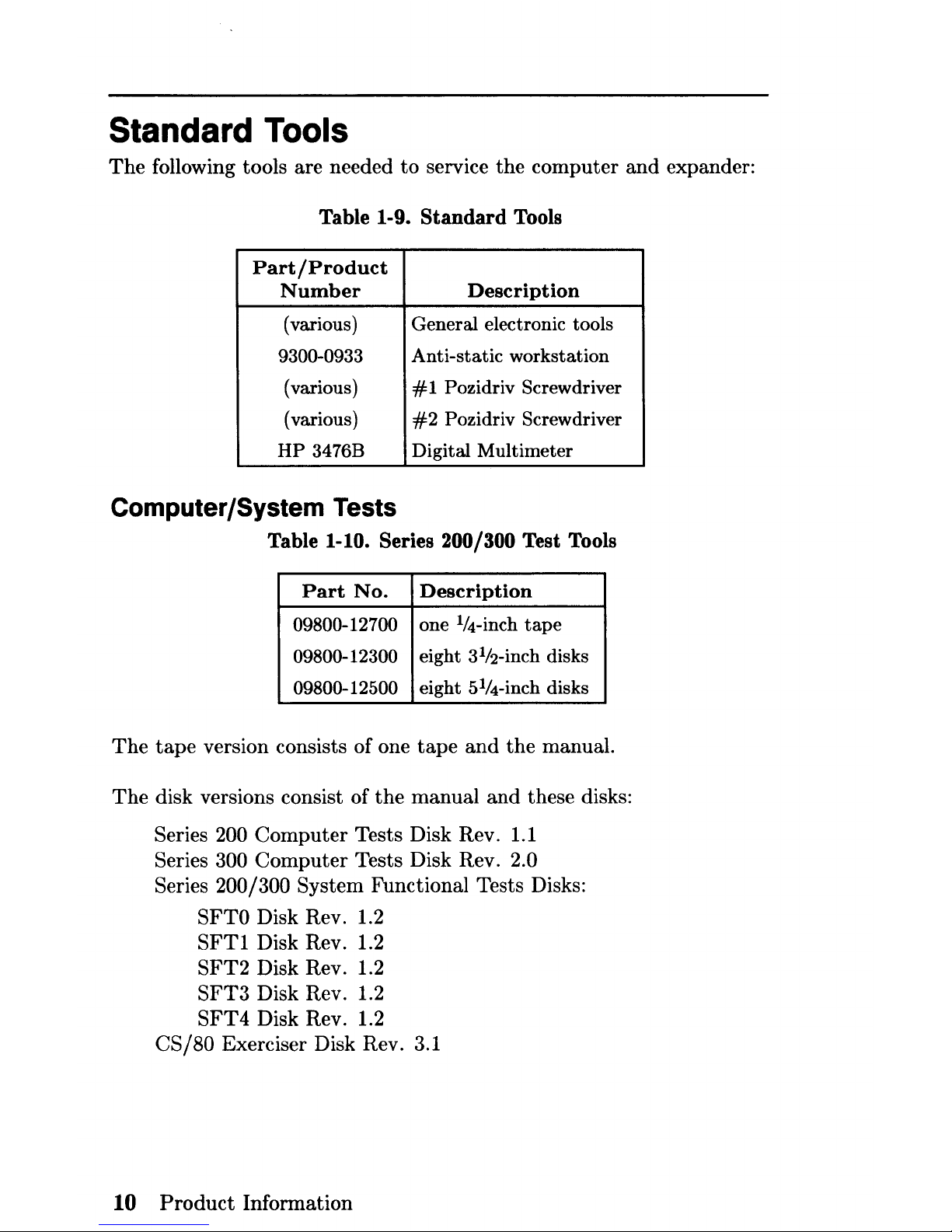
Standard Tools
The
following tools are needed
to
service
the
computer
and
expander:
Table 1-9.
Standard
Tools
Part/Product
Number
Description
(various)
General electronic tools
9300-0933
Anti-static workstation
(various) # 1 Pozidriv Screwdriver
(various)
#2
Pozidriv Screwdriver
HP
3476B Digital
Multimeter
Computer/System Tests
Table 1-10. Series 200/300 Test Tools
Part
No.
Description
09800-12700
one If4-inch
tape
09800-12300
eight 3Ih-inch
disks
09800-12500
eight 5If4-inch disks
The
tape
version consists of one
tape
and
the
manual.
The
disk versions consist of
the
manual
and
these disks:
Series
200
Computer
Tests Disk Rev. 1.1
Series
300
Computer
Tests Disk Rev. 2.0
Series 200/300 System Functional Tests Disks:
SF
TO
Disk Rev. 1.2
SFT1 Disk Rev. 1.2
SFT2
Disk Rev. 1.2
SFT3
Disk Rev. 1.2
SFT4
Disk Rev. 1.2
CS/80
Exerciser Disk Rev. 3.1
10
Product
Information

Environmental/Installation/PM 2
Environmental
Environmental Specifications
Operating temperature
Operating humidity
Operating altitude
Maximum Heat Dissipation
0-
55° C
5 - 95% relative
4572 metres
(15000 feet)
853
Btu/hr
250
Kcal/hr
Electromagnetic Interference
Standards met FCC Class A
VCCI Class 2
VDE Class B,
VDE
1046/84
Regulatory Requirements
Standards met UL 478,
5th
Edition
CSA 154M-1983
IEC 380, 3rd Edition; 435, 2nd Edition
Environmental/Installation/PM
11
 Loading...