

HP 9000 340 Service Manual
Model
340
Workstation's SPU
Service Manual
HP
9000 Series
300
Computers
Model
340
HP
Part
Number 98571-90030
FIIOW
HEWLETT
a:1!II
PACKARD
Hewlett-Packard
Company
3404 East Harmony Road, Fort Collins, Colorado 80525
NOTICE
The information contained
in
this document is sublect to change without notice.
HEWLETT-PACKARD MAKES
NO
WARRANTY
OF
ANY KIND WITH REGARD
TO
THIS MANUAL, INCLUDING, BUT NOT LIMITED
TO,
THE
IMPLIED WARRANTIES
OF
MERCHANTABILITY AND FITNESS
FOR
A PARTICULAR PURPOSE. Hewlett-Packard shall not
be
liable for errors contained herein or direct. indirect. special,
incidental or consequential damages
in
connection with the furnishing, performance, or use of this material.
WARRANTY
A copy
of
the specific warranty terms applicable to your Hewlett-Packard product and replacement parts
can
be
obtained from your local Sales and Service Office.
Copyright © Hewlett-Packard Company 1988
This document contains information which is protected by copyright.
All
rights are reserved. Reproduction, adaptation, or translation without prior written permission IS
prohibited, except as allowed under the copyright laws.
Restricted Rights Legend
Use, duplication or disclosure by the
U.S Government Department of Defense is subject to restrictions
as
set forth
in
paragraph
(bX3Xii)
of the Rights
in
Technical Data and
Software clause
in
FAR
52.227-7013.
Copyright
© AT&T, Inc.
1980,1984
Copyright © The Regents of the University
of
California 1979, 1980, 1983
This software and documentation is based
in
part
on
the Fourth Berkeley Software Distribution under license from the Regents of the University of California
ii
Printing
History
New editions of
this
manual will incorporate all
material
updated
since
the
previous edition.
Update
packages may
be
issued between editions
and
contain replacement
and
additional pages
to
be
merged into
the
manual
by
the
user. Each
updated
page will
be
indicated by a revision
date
at
the
bottom
of
the
page. A vertical
bar
in
the
margin indicates
the
changes on each page.
Note
that
pages whieh are rearranged due
to
changes on a previous page
are
not
considered
revised.
The
manual printing
date
and
part
number
indicate its
current
edition.
The
printing
date
changes when a new edition
is
printed. (Minor corrections
and
updates
which
are
incorporated
at
reprint do
not
cause
the
date
to
change.)
The
manual
part
number
changes when extensive
technical changes
are
incorporated.
October
1988 ... Edition 1
November 1988 ...
Edition
2.
(Several
part
numbers changed
and
this
edition includes
the
new
part
numbers.)
98571~90090,
rev:
11/88
Printing
History iii

iv
Printing
History
Notices
Radio Frequency Interference Statements
IFCC
Statement
Federal Communications Commission
Radio Frequency Interference Statement
(U.S.A. Only)
The
Federal Communications Commission (in
Subpart
J of
Part
15, Docket 20780) has specified
that
the
following notice be brought
to
the
attention
of
the
users of this product.
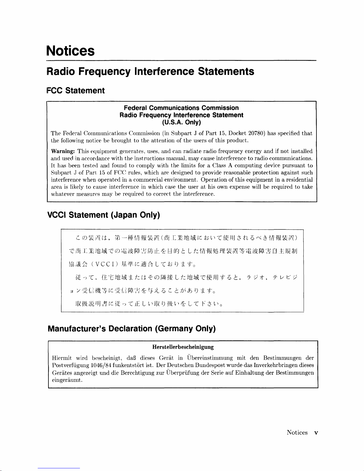
Warning: This equipment generates, uses,
and
can
radiate
radio frequency energy
and
if
not
installed
and
used in accordance
with
the
instructions manual, may cause interference
to
radio communications.
It
has been tested and found
to
comply with
the
limits for a Class A computing device
pursuant
to
Subpart
J of
Part
15
of
FCC
rules, which are designed
to
provide reasonable protection against such
interference when
operated
in a commercial environment.
Operation
of this equipment in a residential
area
is
likely
to
cause interference in which case
the
user
at
his own expense will be required
to
take
whatever measures may be required
to
correct
the
interference.
'VCCI
Statement (Japan Only)
Manufacturer'S Declaration (Germany Only)
Herstellerbescheinigung
Hiermit wird bescheinigt,
daB
dieses
Gerat
in lJbereinstimmung
mit
den Bestimmungen der
Postverfiigung
1046/84 funkentstort ist. Der Deutschen Bundespost wurde das Inverkehrbringen dieses
Gerates angezeigt
und
die Berechtigung zur Uberpriifung der Serie auf
Einhaltung
der Bestimmungen
eingeraumt.
Notices v
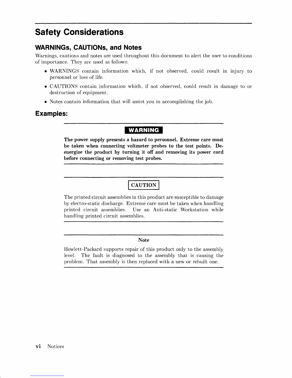
Safety Considerations
WARNINGs, CAUTIONs, and Notes
Warnings,
cautions
and
notes are used
throughout
this
document
to
alert
the
user
to
conditions
of
importance.
They
are
used as follows:
• WARNINGS
contain
information which, if
not
observed, could result in injury
to
personnel
or
loss of life.
•
CAUTIONS
contain
information which, if
not
observed, could result in
damage
to
or
destruction
of
equipment.
• Notes
contain
information
that
will assist you in accomplishing
the
job.
Examples:
vi
Notices
WARNING
The power supply presents a hazard to personnel. Extreme care must
be taken when connecting voltmeter probes to the test points. Deenergize the product by turning it off and removing its power cord
before connecting or removing test probes.
I CAUTION I
The
printed
circuit assenlblies in
this
product
are
susceptible
to
damage
by electro-static discharge.
Extrenle
care
must
be
taken
when
handling
printed
circuit assemblies. Use
an
Anti-static
Workstation
while
handling
printed
circuit assemblies.
Note
Hewlett-Packard
supports
repair of
this
product
only
to
the
assembly
level.
The
fault is diagnosed
to
the
assembly
that
is causing
the
problem.
That
assembly
is
then
replaced
with
a new
or
rebuilt one.

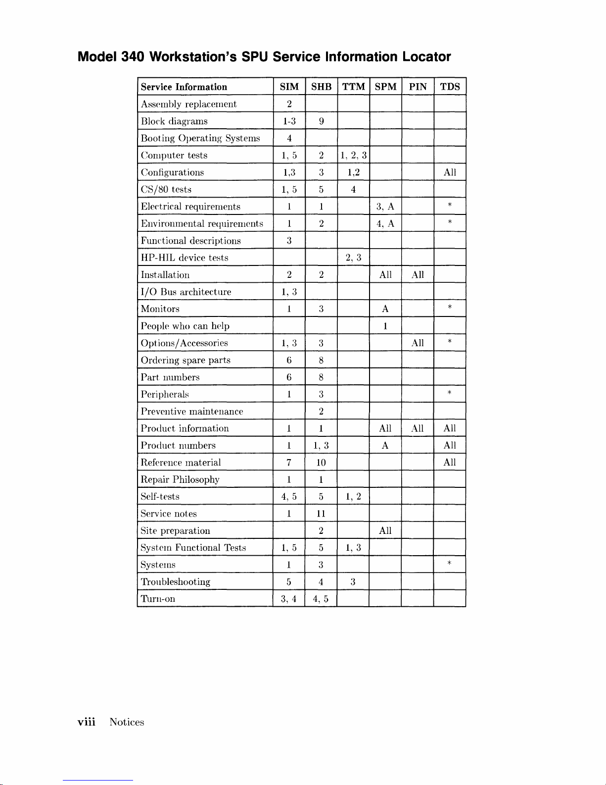
Service Information Locator
On
the
next
page
is
a Service
Information
Locator.
First,
find
the
information
to
reference
in
the
left-hand column. Next, move
to
the
right
to a chapter
number. Last, move
up
to
the
abbreviated
lnanual
title
that
has
the
information
documented.
Chapter
identifiers in
the
Locator
use
the
following codes:
Chapter
N urnber:
Numbers, such as
2.
Inclusive
chapters,
such as 4-6.
Letters, such as A for
Appendix
A. Appendices:
Entire
Manual: All
Varies:
* (Check Table
of
Contents
or
Index.)
M:anuals identified in
this
locator
are
abbreviated
by
their
initials:
Initials
Manual Title
Part Number
81M
Model 340 Workstation's
SPU
Service Information Manual
98571-90030
SHB
Model 340 Workstation's SPU Service Handbook
98.571-90039
TTM
Series 200/300 Test Tools Manual 09800-90011
SPM
HP
9000 Site
Preparation
Manual
09000-90041
PIN
Product
Installation Note
TDS Series 300 Technical
Data
Sheet/Price
List
Video/Graphics Boards Information
These
boards
have service information located in
other
manuals
identified in
the
following table.
Workstation
Model
Part Number
Title
340SRX 98720-·90030
HP
98720A Graphics Display
Station
Hardware
Support
Document
340CH
98550-·90000
HP
98550A Graphics Interface Familiarization Guide
98556-·90000
HP
98556A 2D Graphics Interface Familiarization Guide
340C+
98549-90000
HP
98549A Graphics Interface Familiarization Guide
340MH
98548-·90000
HP
98548A Familiarization Guide
340M
98562-·90030
Model 330/350 Service Information Manual
Notices
vii
Model 340 Workstation's
SPU
Service Information Locator
Service Information
SIM SHB TTM
SPM
PIN
TDS
Assembly
replacement
2
Block
diagrams
1-3
9
Booting
Operating
Systems
4
Computer
tests
1,
5 2
1,2,3
Configurations
1,3
3
1,2 All
CS/80
tests
1,
5
5
4
Electrical requirements 1
1 3, A
*
Environmental
requirements 1 2
4,
A
*
Functional
descriptions
3
HP-HIL
device
tests
2,
3
Installation
2 2
All All
I/O
Bus
architecture
1,3
Monitors
1
3 A
*
People
who
can
help
1
Options
/ Accessories
1,3
3
All
*
Ord(\ring
spare
parts
6
8
Part
numbers
6
8
Peripherals
1
3
*
Preventive
maintenance
2
Product
information
1 1 All All
All
Product
numbers
1
1,3
A
All
Reference
material
7
10
All
Repair
Philosophy 1
1
Self-tests
4,
5
5
1,2
Service
notes
1
11
Site
preparation
2 All
System
Functional
Tests
1,
5
5
1,3
Systems
1
3
*
TrOll
bleshooting
5
4 3
Turn-on
3, 4
4,
5
viii
Notices
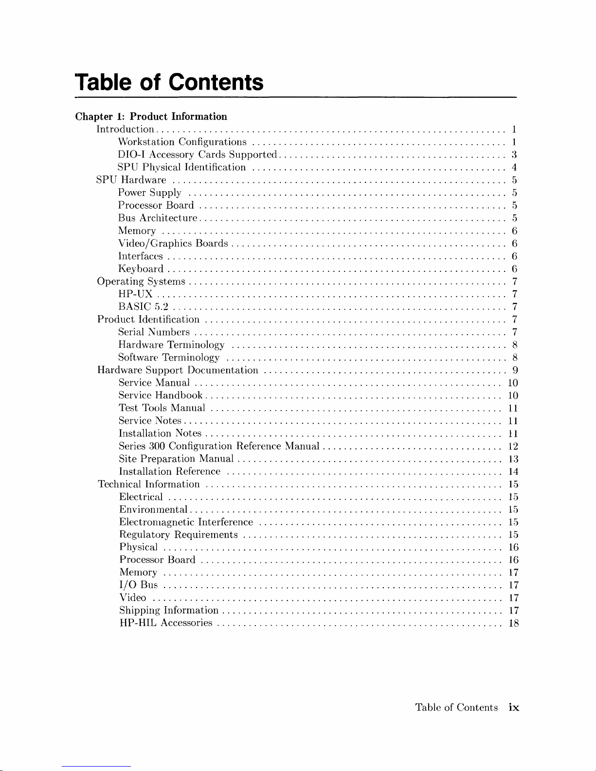
Table of Contents
Chapter
1::
Product Information
Introcluctiorl. . . . . . . . . . . . . . . . . . . . . . . . . . . . . . . . . . . . . . . . . . . . . . . . . . . . . . . . . . . . . . . .
..
1
VVorkstation
Configurations
..
. . . . . . . . . . . . . . . . . . . . . . . . . . . . . . . . . . . . . . . . . . . .
..
1
DIO-I
Accessory
Cards
Supported
.........................................
"
:~
SPU
Physical
Identification
................................................
4
SPU
l-Iard
ware
................................................................
5
P'ower
SUf>ply
............................................................
5
Processor
Board
. . . . . . . . . . . . . . . . . . . . . . . . . . . . . . . . . . . . . . . . . . . . . . . . . . . . . . . .
..
5
Bus
Architecture.
. . . . . . . . . . . . . . . . . . . . . . . . . . . . . . . . . . . . . . . . . . . . . . . . . . . . . . .
..
5
l\1elnory
..................................................................
6
Video/Graphics
Boards
....................................................
6
Illterfaces
.. " .............................................................
6
!(ey
l)oard
..
" . . . . . . . . . . . . . . . . . . . . . . . . . . . . . . . . . . . . . . . . . . . . . . . . . . . . . . . . . . .
..
6
Operating
Systemls . . . . . . . . . . . . . . . . . . . . . . . . . . . . . . . . . . . . . . . . . . . . . . . . . . . . . . . . . .
..
7
I-J[P-UX , ... " .............................................................
7
E:ASIC 5.2 .
..
. . . . . . . . . . . . . . . . . . . . . . . . . . . . . . . . . . . . . . . . . . . . . . . . . . . . . . . . . . .
..
7
Product
Identification
.........................................................
7
Serial N urnbers . . . . . . . . . . . . . . . . . . . . . . . . . . . . . . . . . . . . . . . . . . . . . . . . . . . . . . . . .
..
7
Hardware
Ternlinology
....................................................
8
Software
Tenninology
.....................................................
8
Hardware
Support
Docunlentation
.....
. . . . . . . . . . . . . . . . . . . . . . . . . . . . . . . . . . . . . . .
..
9
Service
Manual
. . . . . . . . . . . . . . . . . . . . . . . . . . . . . . . . . . . . . . . . . . . . . . . . . . . . . . . .
..
10
Service
Handbook
........................................................
10
Test
Tools
Manual
. . . . . . . . . . . . . . . . . . . . . . . . . . . . . . . . . . . . . . . . . . . . . . . . . . . . .
..
11
Service
Notes.
. . . . . . . . . . . . . . . . . . . . . . . . . . . . . . . . . . . . . . . . . . . . . . . . . . . . . . . . .
..
11
Installation
Notes.
. . . . . . . . . . . . . . . . . . . . . . . . . . . . . . . . . . . . . . . . . . . . . . . . . . . . .
..
11
Series 300
Configuration
Reference
Manual.
. . . . . . . . . . . . . . . . . . . . . . . . . . . . . . .
..
12
Site
Preparation
Manual.
. . . . . . . . . . . . . . . . . . . . . . . . . . . . . . . . . . . . . . . . . . . . . . .
..
13
Installation
Reference
....................................................
14
Technical
Information
........................................................
1.5
E:lectrieal
.....
. . . . . . . . . . . . . . . . . . . . . . . . . . . . . . . . . . . . . . . . . . . . . . . . . . . . . . . .
..
15
Enviromnental.
. . . . . . . . . . . . . . . . . . . . . . . . . . . . . . . . . . . . . . . . . . . . . . . . . . . . . . . .
..
15
Electronlagnetic
Interference
..............................................
1.5
Regulatory
Requirements
..
. . . . . . . . . . . . . . . . . . . . . . . . . . . . . . . . . . . . . . . . . . . . .
..
15
F'hysical
................................................................
16
Processor
Board
.........................................................
16
~1:emory
................................................................
17
I/C)
Bus
................................................................
17
\Tideo
..................................................................
17
Shipping
Infornlation
. . . . . . . . . . . . . . . . . . . . . . . . . . . . . . . . . . . . . . . . . . . . . . . . . . .
..
17
HP-HIL
Accessories
......................................................
18
Table
of
Contents
ix
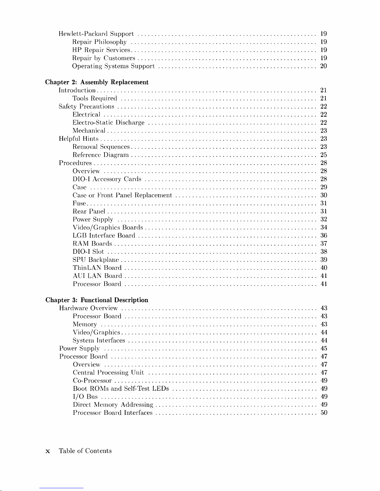
Hewlett-Packard
Support
.....................................................
19
Repair
Philosophy
.......................................................
19
HP
Repair
Services. . . . . . . . . . . . . . . . . . . . . . . . . . . . . . . . . . . . . . . . . . . . . . . . . . . . .
..
19
Repair
by
Customers
...................................................
" 19
Operating
Systenls
Support
.............................................
"
20
Chapter
2:
Assembly Replacement
Introduction
...............................................................
"
21
Tools
Required
..........................................................
21
Safety
Precautions
. . . . . . . . . . . . . . . . . . . . . . . . . . . . . . . . . . . . . . . . . . . . . . . . . . . . . . . . .
..
22
Electrical
...............................................................
22
Electro-Static
Discharge
..................................................
22
Mechanical
............................................................
"
23
Helpful
Hints.
. . . . . . . . . . . . . . . . . . . . . . . . . . . . . . . . . . . . . . . . . . . . . . . . . . . . . . . . . . . . .
..
23
RenlOval Sequences
.....................................................
"
23
Reference
Diagram
.....................................................
"
25
Proced
ures
................................................................
"
28
Overview
...............................................................
28
DIO-1 Accessory
Cards
...................................................
28
Case
...................................................................
29
Case
or
Front
Panel
Replacenlent
........................................
" 30
Fuse
....................................................................
31
Rear
Panel
............................................................
"
31
Power
Supply
...........................................................
32
Video/Graphics
Boards
...................................................
34
LGn
Interface
Board
.....................................................
36
R,AM
Boards
..........................................................
" 37
DIO-I Slot
............................................................
" 38
SPU
Backplane
........................................................
" 39
ThinLAN
Board
.......................................................
" 40
AUI
LAN
Board
.......................................................
"
41
Processor
Board
.......................................................
"
41
Chapter
3:
Functional Description
Hardware
Overview
...
. . . . . . . . . . . . . . . . . . . . . . . . . . . . . . . . . . . . . . . . . . . . . . . . . . . . .
..
43
Processor
Board
.......................................................
" 43
Meillory
................................................................
43
Video /
Graphics
........................................................
" 44
System
Interfaces
......................................................
" 44
Power Supply
...............................................................
45
Processor
Board
.............................................................
47
Overview
...........................................
"...................
47
Central
Processing
Unit
..............................
'
..................
" 47
Co-
Processor
...........................................................
" 49
Boot
ROMs
and
Self-Test
LEDs
...
. . . . . . . . . . . . . . . . . . . . . . . . . . . . . . . . . . . . . .
..
49
I/O
BllS
..............................................................
" 49
Direct
Memory
Addressing.
. . . . . . . . . . . . . . . . . . . . . . . . . . . . . . . . . . . . . . . . . . . . .
..
49
Processor
Board
Interfaces
..............................................
" 50
x
Table
of
Contents
RS-232 Interface
.........................................................
50
HP-IB Interface
..........................................................
51
HP-HIL Interface/Devices
.................................................
52
LAN Interface Boards . . . . . . . . . . . . . . . . . . . . . . . . . . . . . . . . . . . . . . . . . . . . . . . . . . . . . .
..
56
ThinLAN
Board
. . . . . . . . . . . . . . . . . . . . . . . . . . . . . . . . . . . . . . . . . . . . . . . . . . . . . . .
..
56
AUI
LA='J
Board
.........................................................
57
Memory
.......................
'"
..............................
"
..........
58
Introduction.
. . . . . . . . . . . . . . . . . . . . . . . . . . . . . . . . . . . . . . . . . . . . . . . . . . . . . . . . . .
..
58
RAM Architecture
......................................................
, 58
RAM
Configuration . . . . . . . . . . . . . . . . . . . . . . . . . . . . . . . . . . . . . . . . . . . . . . . . . . . .
..
59
Video/Graphics
Boards
.......................................................
61
Small
Computer
Systems Interface . . . . . . . . . . . . . . . . . . . . . . . . . . . . . . . . . . . . . . . . . . .
..
62
SCSI Overview
..........................................................
62
Configuration
...........................................................
64
(jal)ling . . . . . . . . . . . . . . . . . . . . . . . . . . . . . . . . . . . . . . . . . . . . . . . . . . . . . . . . . . . . . . .
..
65
Third-Party
Issues
..........................................
,
............
65
Functional Description
.......................................
'
............
66
High-Speed
HP-IB
..........................................
,
............
67
Chapter
4:
Boot ROM Functions
Introd.uction. . . . . . . . . . . . . . . . . . . . . . . . . . . . . . . . . . . . . . . . . . . . . . . . . . . . . . . . . . . . . . .
..
69
Power-Up/Self-Test Sequence
..................................................
69
Configure Mode Software Override . . . . . . . . . . . . . . . . . . . . . . . . . . . . . . . . . . . . . . .
..
71
Extended
Testing . . . . . . . . . . . . . . . . . . . . . . . . . . . . . . . . . . . . . . . . . . . . . . . . . . . . . .
..
72
The
Human
Interface
.....................................................
72
Relnote
Human
Interface
.................................................
73
Srnall COlnputer Systems Interface
.........................................
76
Booting
Operating
Systems
...................................................
78
Boot System Selection . . . . . . . . . . . . . . . . . . . . . . . . . . . . . . . . . . . . . . . . . . . . . . . . . .
..
78
Boot System
Priority
Control.
. . . . . . . . . . . . . . . . . . . . . . . . . . . . . . . . . . . . . . . . . . .
..
80
Supported
Boot Configurations
............................................
81
LAN Boot
Operations
. . . . . . . . . . . . . . . . . . . . . . . . . . . . . . . . . . . . . . . . . . . . . . . . . .
..
81
Chapter
5:
Troubleshooting
Intro,dllction . . . . . . . . . . . . . . . . . . . . . . . . . . . . . . . . . . . . . . . . . . . . . . . . . . . . . . . . . . . . . . .
..
83
Analytic Troubleshooting
....................
. . . . . . . . . . . . . . . . . . . . . . . . . . .
..
83
lvIaterials
Required.
. . . . . . . . . . . . . . . . . . . . . . . . . . . . . . . . . . . . . . . . . . . . . . . . . . . .
..
83
Test LED Displays
.......................................................
83
Troubleshooting
Procedures.
. . . . . . . . . . . . . . . . . . . . . . . . . . . . . . . . . . . . . . . . . . . . . . . .
..
84
\Vorkstation Level. . . . . . . . . . . . . . . . . . . . . . . . . . . . . . . . . . . . . . . . . . . . . . . . . . . . . .
..
84
SPU
Troubleshooting.
. . . . . . . . . . . . . . . . . . . . . . . . . . . . . . . . . . . . . . . . . . . . . . . . . .
..
84
Inoperative
Unit
Procedure
...................................................
85
Live
Unit
Procedure
..........................................................
86
Minimum
Configuration
..................................................
86
Functional
Unit Troubleshooting
...............................................
87
SCSI Test
Connector.
. . . . . . . . . . . . . . . . . . . . . . . . . . . . . . . . . . . . . . . . . . . . . . . . . .
..
87
:\1inimum Configuration
..................................................
88
Table of
Contents
xi

Self-Test . . . . . . . . . . . . . . . . . . . . . . . . . . . . . . . . . . . . . . . . . . . . . . . . . . . . . . . . . . . . . . . . . .
..
89
Failure
Indications
.......................................................
89
General Description
of
LED
Failure Codes
..................................
90
Other
Failure
Indicat
ions
.................................................
94
LAN
Boot
Failures
.......................................................
95
Diagnostic
Progranls
. . . . . . . . . . . . . . . . . . . . . . . . . . . . . . . . . . . . . . . . . . . . . . . . . . . . . . .
..
97
HP-UX
Diagnostics
......................................................
97
Series 200/300 Test Tools
.................................................
9S
Series 300
System
Support
Tape
. . . . . . . . . . . . . . . . . . . . . . . . . . . . . . . . . . . . . . . . .
..
99
Chapter
6:
Parts
Lists
Parts
Information
...........................................................
101
Introduction.
. . . . . . . . . . . . . . . . . . . . . . . . . . . . . . . . . . . . . . . . . . . . . . . . . . . . . . . . .
..
101
Cooperative
Support
Program
............................................
101
Exchange
Parts
.........................................................
101
Parts
List.
. . . . . . . . . . . . . . . . . . . . . . . . . . . . . . . . . . . . . . . . . . . . . . . . . . . . . . . . . . . . . . .
..
102
Chapter
7:
References
Irltroduction.
. . . . . . . . . . . . . . . . . . . . . . . . . . . . . . . . . . . . . . . . . . . . . . . . . . . . . . . . . . . . .
..
105
Service Information
Locator.
. . . . . . . . . . . . . . . . . . . . . . . . . . . . . . . . . . . . . . . . . . . . . . .
..
105
Localized System Identification . . . . . . . . . . . . . . . . . . . . . . . . . . . . . . . . . . . . . . . . . . . . .
..
105
Related
Hardware
Documentation.
. . . . . . . . . . . . . . . . . . . . . . . . . . . . . . . . . . . . . . . . . .
..
107
Hardware
Support
Documentation
. . . . . . . . . . . . . . . . . . . . . . . . . . . . . . . . . . . . . .
..
107
Installation
Manuals/Notes.
. . . . . . . . . . . . . . . . . . . . . . . . . . . . . . . . . . . . . . . . . . . .
..
lOS
Document
Binders . . . . . . . . . . . . . . . . . . . . . . . . . . . . . . . . . . . . . . . . . . . . . . . . . . . .
..
lOS
xii
Table of
Contents
Product
Information
1
Introduction
Model 340
Workstation
SysterIl Processing
Unit's
(SPU's)
are
market
entry
level versions of
the
Model
:360
and
370 computers.
Each
provides good performance
at
low
cost
to
meet
the
computer-·intensi
ve
requirements for design
automation
as well as scientific analysis
and
general
purpose
cornputation.
These
SPU's
are also
an
enhanced
versions
of
the
Model 318
and
319
Workstation
SPUs
with
improved video
and
graphics capabilities,
added
interfaces,
and
a faster
clock speed.
The
SPU
is a lirIlited-configuration
product.
Depending
on
the
workstation model, one
of
several
video/graphics
boards
is used.
It
is
upgradeable
for memory
and
has
LAN, High-Speed
HP-
IB
or
SCSI interface options.
Certain
user-installable
DIO
accessory
cards
can
be
used if
the
HP
98013A DIO Slot
is
installed. No
expanders
are
available for
the
Model
.340
Workstation's
SPU.
Each
SPU
is cOlIlplete within
the
case. All Illemory, interfacing, video
and
processing functions
occur
within
the
case.
Workstation
Configurations
Several configurations are available. You should refer
to
the
current
HP
9000 Series
300
Pricing
Information
and Technical Data Sheets
to
find
out
exactly
what
is
currently
offered.
Different aIllounts
of
memory
and
interface
options
are
available for
installation
by qualified
service personnel.
Product
Information
1
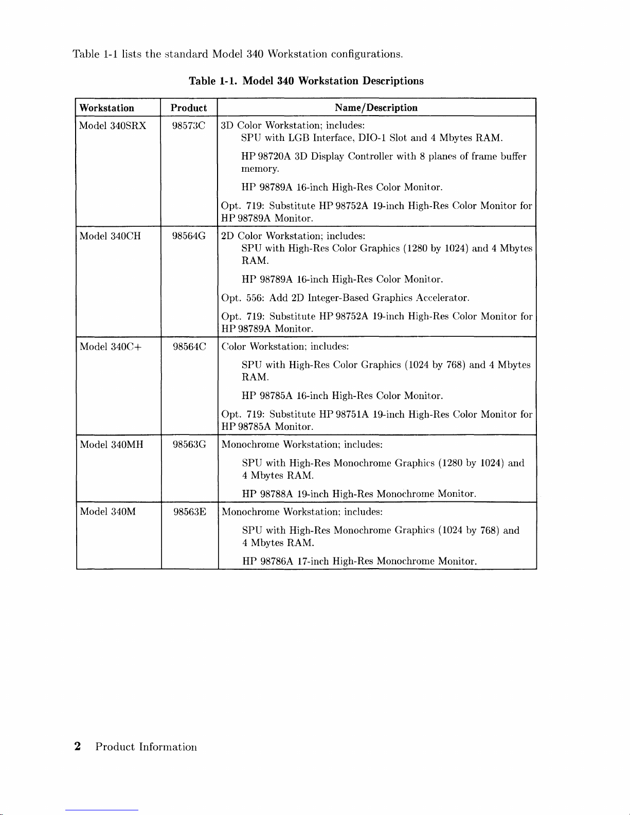
Table
1-1
lists
the
standard
Model 340 Workstation configurations.
Table 1-1. Model
340 Workstation Descriptions
Workstation Product
N
arne
/Description
Model 340SRX 98573C
3D Color Workstation; includes:
SPU
with
LGB Interface, DIO-1 Slot
and
4 Mbytes RAM.
HP
98720A 3D Display Controller with 8 planes of frame buffer
memory.
HP
98789A 16-inch High-Res Color Monitor.
Opt.
719:
Substitute
HP
98752A 19-inch High-Res Color Monitor for
HP
98789A Monitor.
Model
340CH
98564G 2D Color Workstation; includes:
SPU
with High-Res Color Graphics (1280 by 1(24)
and
4 Mbytes
RAM.
HP
98789A 16-inch High-Res Color Monitor.
Opt. 556: Add
2D
Integer-Based Graphics Accelerator.
Opt.
719:
Substitute
HP
98752A 19-inch High-Res Color Monitor for
HP
98789A Monitor.
Model
340C+
98564C
Color Workstation; includes:
SPU
with High-Res Color Graphics (1024 by 768)
and
4 Mbytes
RAM.
HP
98785A 16-inch High-Res Color Monitor.
Opt.
719:
Substitute
HP
98751A 19-inch High-Res Color Monitor for
HP
98785A Monitor.
Model
340MH
98563G Monochrome Workstation; includes:
SPU with High-Res Monochrome Graphics (1280 by 1024)
and
4 Mbytes RAM.
HP
98788A 19-inch High-Res Monochrome Monitor.
Model
340M
98563E
Monochrome Workstation; includes:
SPU
with High-Res Monochrome Graphics (1024 by 768)
and
4 Mbytes RAM.
HP
98786A 17-inch High-Res Monochrome Monitor.
2
Product
Information
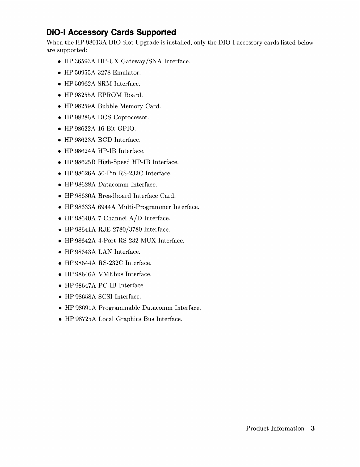
1010-1
Accessory Cards Supported
When
the
HP
9801:3A
DIO Slot Upgrade is installed, only
the
DIO-I accessory cards listed below
are supported:
•
HP
3t>59JA
HP-·UX Gateway
/SNA
Interface.
•
HP
50955A 3278 Emulator.
•
HP
50962A
SR~1
Interface.
•
HP
98255A
EPROM
Board.
•
HP
98259A Bubble Memory Card.
•
HP
98286A DOS Coprocessor.
•
HP
98622A 16-Bit GPIO.
•
HP
9862:3A
BCD
Interface.
•
HP
98624A HP-·IB Interface.
•
HP
98625B High-Speed HP-IB Interface.
•
HP
98626A 50-Pin RS-232C Interface.
•
HP
98628A
Datacomm
Interface.
•
HP
98630A
Breadboard
Interface Card.
•
HP
9863:3A
G944A
Multi-Programmer Interface.
•
HP
98640A 7 -Channel
A/D
Interface.
•
HP
98641A
RJE
2780/3780 Interface.
•
HP
98642A 4-Port RS-232 MUX Interface.
•
HP
9864:3A
LAN Interface.
•
HP
98644A RS- 232C Interface.
•
HP
9864GA
VM:Ebus Interface.
•
HP
98647A PC·-IB Interface.
•
HP
98658A SCSI Interface.
•
HP
98691A
Programmable
Datacomm
Interface.
•
HP
98725A Local Graphics Bus Interface.
Product
Information 3
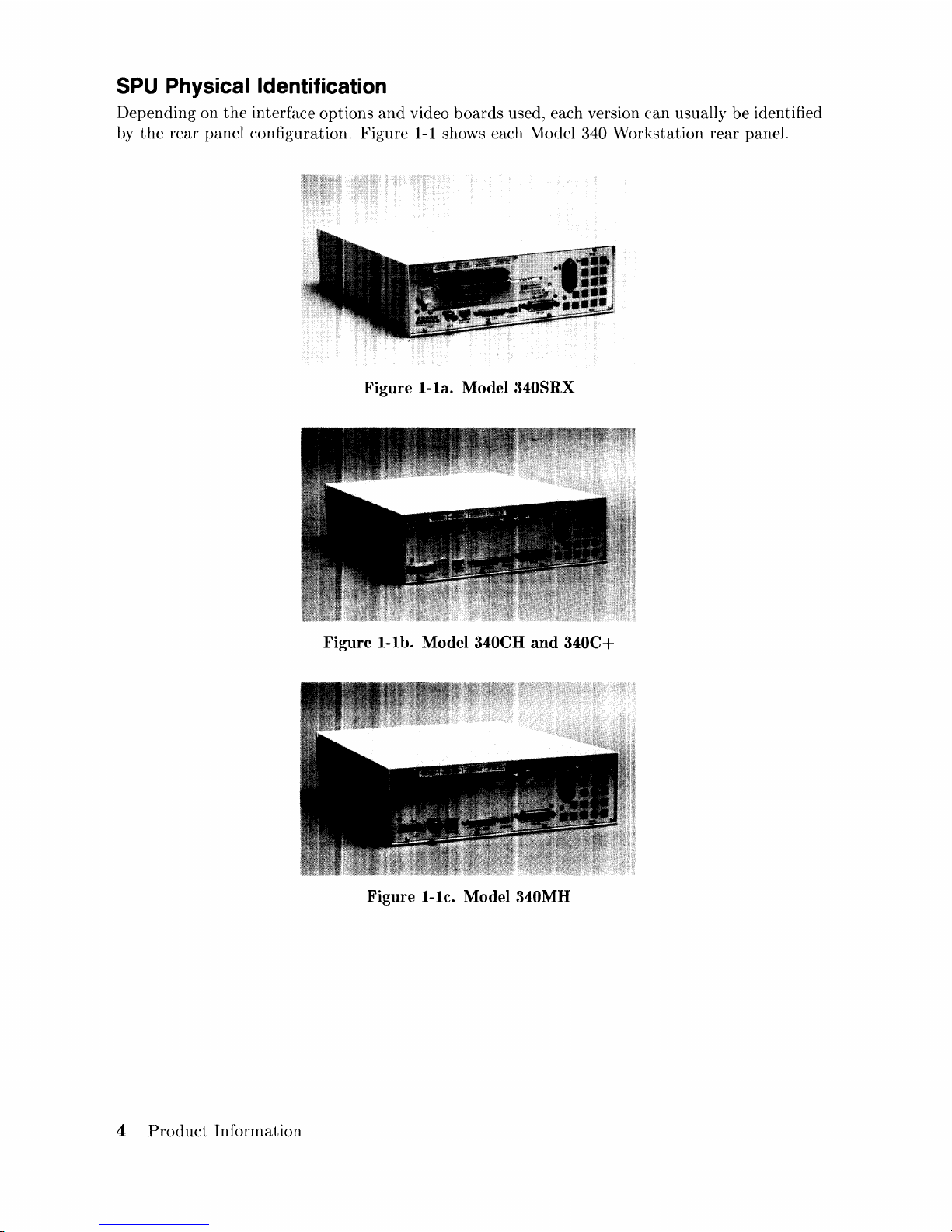
SPU Physical Identification
Depending on
the
interface
options
and
video
boards
used, each version
can
usually
be
identified
by
the
rear
panel configuration. Figure
1-1
shows each Model
~340
Workstation
rear
panel.
Figure
l-la.
Model 340SRX
Figure
I-lb.
Model 340CH and
340C+
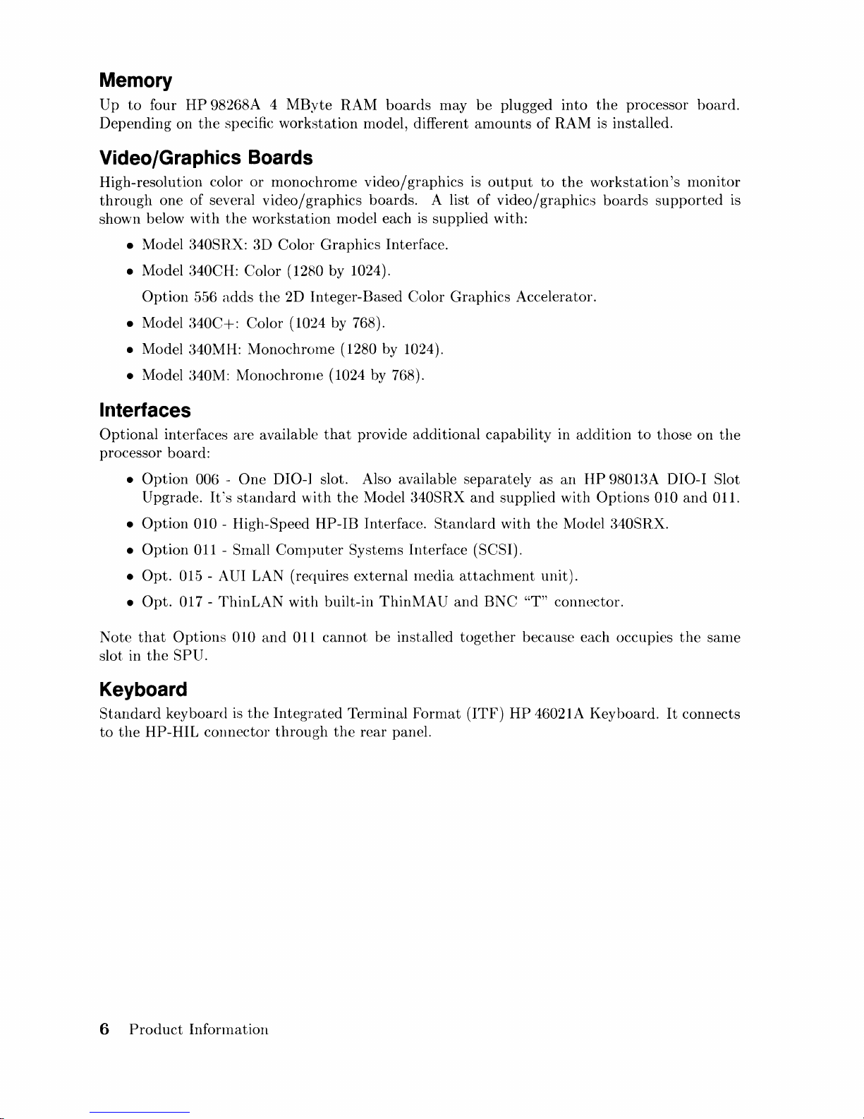
Figure I-Ie. Model 340MH
4
Product
Information
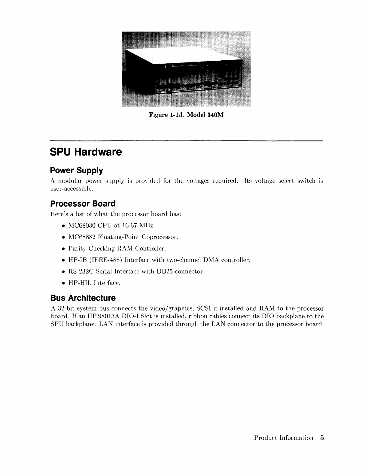
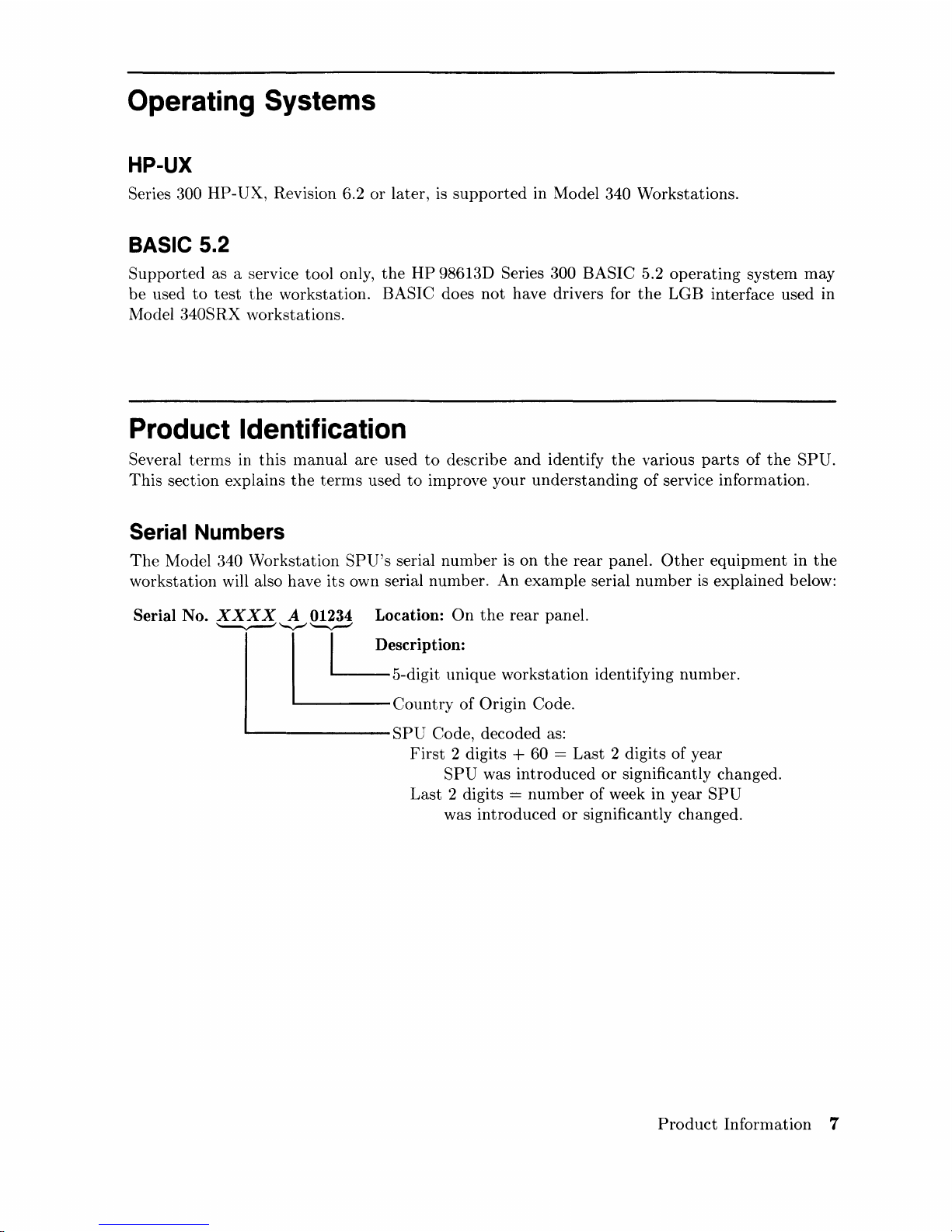
Figure I-Id. Model 340M
SPU Hardware
Power Supply
A
modular
power supply
is
provided for
the
voltages required.
Its
voltage select switch IS
user-accessible.
Processor Board
Here's a
llist
of
what
the
processor
board
has:
• MC680:30 CPt:"
at
16.67 MHz.
• MC68882
Floating-Point
Coprocessor.
• Parity-Checking
RAM
Controller.
•
HP-IB
(IEEE-488) Interface
with
two-channel
DMA
controller.
•
RS-2:~2C
Serial Interface
with
DB25 connector.
•
HP-HIL
[nterface.
Bus Architecture
A 32-bit systern bus connects
the
video/graphics, SCSI if installed
and
RAM
to
the
processor
board.
If
an
HP
98013A DIO-I Slot
is
installed,
ribbon
cables connect its
DIO
backplane
to
the
SPU
backplane. LAN interface is provided
through
the
LAN connector
to
the
processor
board.
Product
Information
5
Memory
Up
to
four
HP
Depending
on
the
98268A 4
specific
MByte
workstation
RAM
boards
model, different
Video/Graphics Boards
High-resolution color
through
shown below
one of several
with
• Model 340SRX: 3D Color Graphics Interface.
• Model 340CH: Color (1280 by 1024).
or
monochrome
video/graphics
the
workstation
video/graphics
boards. A list
model each
may
be
amounts
is
output
of
is
supplied with:
plugged into
of
RAM
to
the
video/graphics
the
processor board.
is
installed.
workstation's
boards
supported
monitor
is
Option
• Model
• Model 340MH: MonochrOlne (1280 by 1024).
•
Model
556
adds
the
340C+:
:~40M:
Color (1024 by 768).
Monochrome (1024 by 768).
2D Integer-Based Color
Interfaces
Optional
processor board:
Note
slot in
interfaces are available
•
Option
Upgrade.
•
Option
•
Option
•
Opt.
•
Opt.
that
the
006 -
It's
010 - High-Speed
011 - Snlall
015 - AUI LAN (requires
017 -
ThinLAN
Options
SPU.
010
that
provide
One
DIO-I slot. Also available
standard
with
Computer
with
and
OIL
the
Model 340SRX
HP-IB
Interface.
Systems Interface (SCSI).
external
built-in
cannot
be
ThinMAU
Keyboard
Standard
to
the
keyboard
HP-HIL
is
the
connector
Integrated
through
the
Terminal
rear
additional
Standard
media
installed
Format
panel.
Graphics
capability in
separately
and
supplied with
with
attachment
and
BNC
together
(ITF)
HP
Accelerator.
addition
as
an
HP
the
lVlodel
unit).
"T"
connector.
because each occupies
46021A Keyboard.
to
9801:~A
Options
340SRX.
those on
DIO-I Slot
010
and
the
It
connects
the
OIl.
same
6
Product
Information
Operating Systems
HP-UX
Series 300
HP-UX,
Revision 6.2
or
later,
is
supported
in Model 340 Workstations.
BASIC 5.2
Supported
as a serviee tool only,
the
HP
9861~~D
Series 300 BASIC 5.2
operating
system
may
be
used
to
test
the
workstation. BASIC does
not
have drivers for
the
LGB interface used in
Model
340SRX workstations.
Product Identification
Several
terms
in
this
manual
are
used
to
describe
and
identify
the
various
parts
of
the
SPU.
This
section explains
the
terms
used
to
improve your
understanding
of
service information.
Serial Numbers
The
Model 340
Workstation
SPU's
serial
number
is
on
the
rear
panel.
Other
equipment
in
the
workstation will also have
its
own serial number.
An
example
serial
number
is
explained below:
Serial No.
XXXX
A 01234 Location:
On
the
rear
panel.
~~'-v-'"
I I Description:
5-digit
unique
workstation
identifying
number.
Country
of
Origin Code.
'---------SPU
Code, deeoded as:
First
2 digits + 60 =
Last
2 digits of year
SPU
was
introduced
or
significantly ehanged.
Last
2 digits =
number
of
week in year
SPU
was
introduced
or
significantly changed.
Product
Information
7
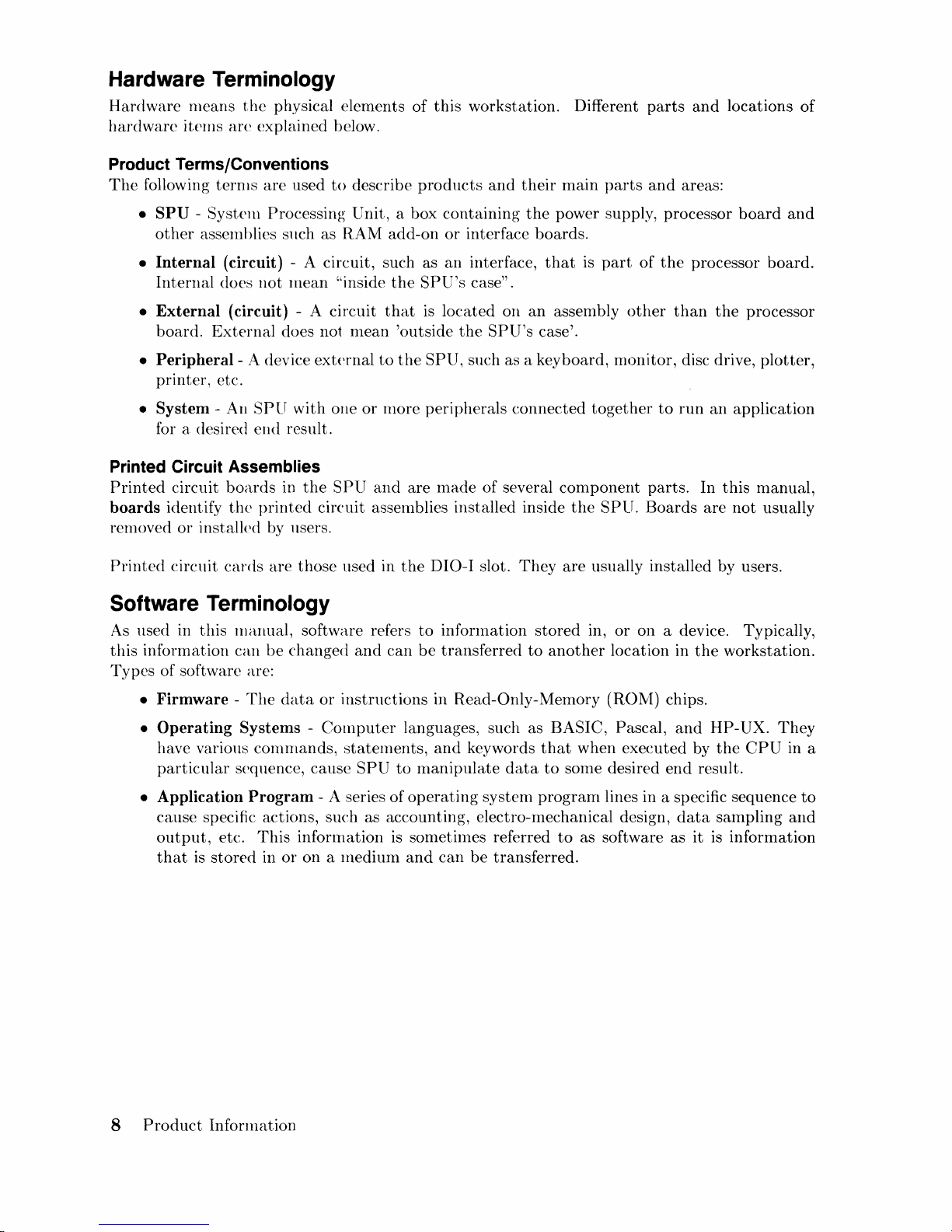
Hardware Terminology
Hardware
means
the
physical elements
of
this
workstation. Different
parts
and
locations
of
hardware
items
arc
explained below.
Product Terms/Conventions
The
following
terms
are
used
to
describe
products
and
their
main
parts
and
areas:
•
SPU
- System Processing Unit, a box containing
the
power supply, processor
board
and
other
assemblies
sHch
as RAM add-on
or
interface boards.
•
Internal
(circuit) - A circuit, such as
an
interface,
that
is
part
of
the
processor
board.
Internal
does
not
mean
"inside
the
SPU's
case" .
•
External
(circuit) - A circuit
that
is located on
an
assembly
other
than
the
processor
board.
External
does not mean 'outside
the
SPU's
case'.
•
Peripheral-
A device
external
to
the
SPU, such as a keyboard, monitor, disc drive,
plotter,
printer, etc.
•
System
- An
SPU
with
OIle
or
more peripherals connected
together
to
run
an
application
for a desired
end
result.
Printed Circuit Assemblies
Printed
circuit
boards
in
the
SPU
and
are
made
of several
component
parts. In
this
manual,
boards
identify
the
printed
circuit assemblies installed inside
the
SPU.
Boards
are
not
usually
removed
or
installed by llsers.
Printed
circuit
cards
are
those
llsed in
the
DIO-I slot.
They
are
usually installed by users.
Software Terminology
As
used in
this
manual, software refers
to
infonnation
stored
in,
or
on a device. Typically,
this
information can
be
changed
and
can
be
transferred
to
another
location in
the
workstation.
Types
of software are:
•
Firmware -The
data
or
instructions
in Read-Only-Memory (RONI) chips.
•
Operating
Systems -Computer
languages, such as BASIC, Pascal,
and
HP-UX.
They
have various
commands,
statements,
and
keywords
that
when executed by
the
CPU
in a
particular
sequence, cause
SPU
to
manipulate
data
to
SOlIle
desired
end
result.
• Application
Program
- A series of
operating
system prograrn lines in a specific sequence
to
cause specific actions, such as accounting, electro-mechanical design,
data
sampling
and
output,
etc.
This
information
is
sometilnes referred
to
as software as
it
is
information
that
is
stored
in
or
on
a lnedium
and
can
be
transferred.
8
Product
Information
Hardware Support Documentation
The
purpose
of
this
SPU's
Hardware
Documentation
is
to
support
the
installation
and
mainte-
nance
of
these
products.
Hardware
Support
Documentation
consists
of
these
manuals
for
the
HP
9000 Series
:300
Model 340
Workstation's
SPU:
• Service ManuaL
• Service
Handbook.
• Service Notes.
• Series 200/:300 Test Tools
Manual.
•
HP
9000 Series
200/300/500
Site
Preparation
Manual.
• Series 300 Con1puter
System
Configuration
Reference.
The
following Inanuals also
relate
to
hardware:
• Various
Installation
Notes.
• Series 300
Installation
Reference.
• Series 200/:300
Peripheral
Installation
Guide.
A
complete
listing
of
titles
and
part
numbers
is in
Chapter 7 of
this
manual
and
the
SPU's
Service
Handbook,
Chapter
10.
Product
Information
9
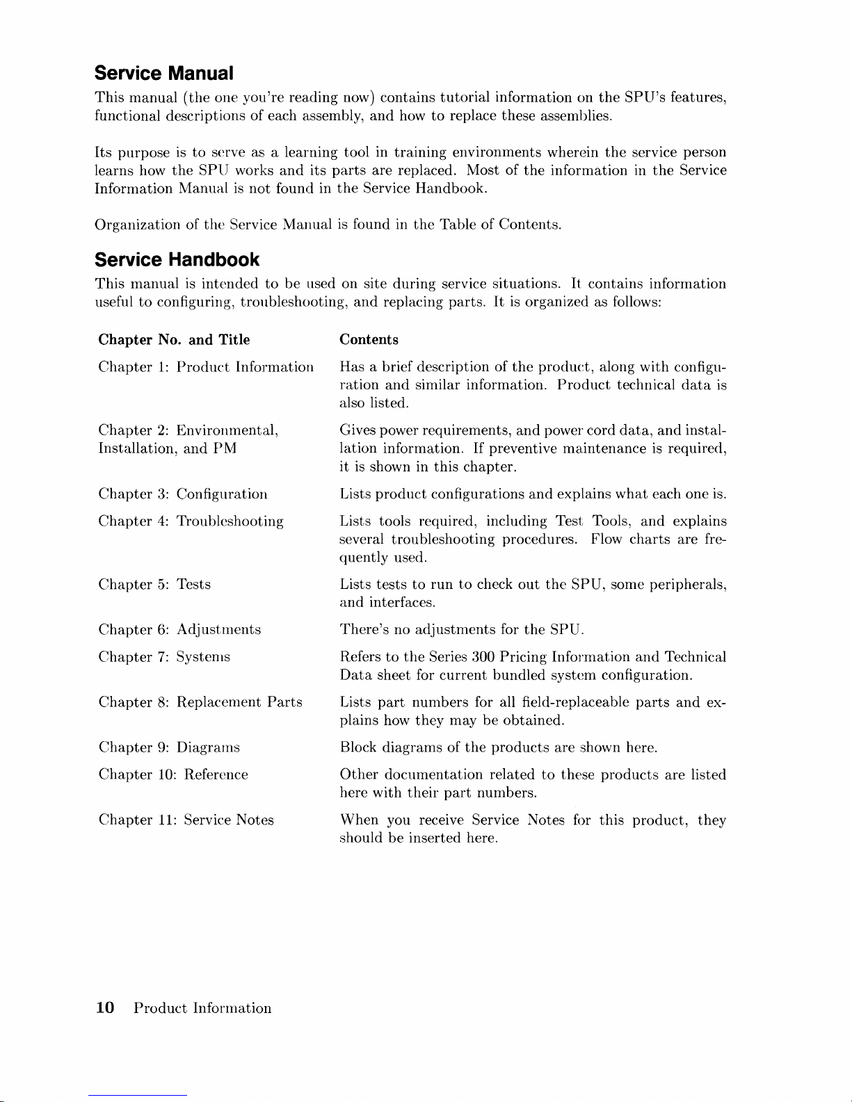
Service Manual
This
manual
(the
one
you're
reading now) contains
tutorial
information on
the
SPU's
features,
functional descriptions
of
each assembly,
and
how
to
replace these assemblies.
Its
purpose
is
to
serve as a learning tool in
training
environments wherein
the
service person
learns how
the
SPU
works
and
its
parts
are replaced. Most
of
the
information in
the
Service
Information
Manual
is
not
found in
the
Service Handbook.
Organization
of
the
Service
Manual
is
found in
the
Table
of
Contents.
Service Handbook
This
manual
is
intended
to
be
used on site
during
service situations.
It
contains information
useful
to
configuring, troubleshooting,
and
replacing
parts.
It
is organized as follows:
Chapter
No.
and
Title
Chapter
1:
Product
Information
Chapter
2:
Environmental,
Installation,
and
PM
Chapter
3:
Configuration
Chapter
4:
Troubleshooting
Chapter
5:
Tests
Chapter
6:
Adj
ust
ments
Chapter
7:
Systems
Chapter
8:
Replacement
Parts
Chapter
9:
Diagrams
Chapter
10:
Reference
Chapter
11:
Service Notes
10
Product
Information
Contents
Has a brief description of
the
product,
along
with
configu-
ration
and
similar information.
Product
technical
data
is
also listed.
Gives power requirements,
and
power cord
data,
and
instal-
lation information.
If
preventive
maintenance
is
required,
it is shown in
this
chapter.
Lists
product
configurations
and
explains
what
each one is.
Lists tools required, including Test Tools,
and
explains
several
troubleshooting
procedures. Flow
charts
are
fre-
quently used.
Lists
tests
to
run
to
check
out
the
SPU,
some peripherals,
and
interfaces.
There's
no
adjustments
for
the
SPU.
Refers
to
the
Series 300
Pricing
Information
and
Technical
Data
sheet for
current
bundled
system
configuration.
Lists
part
nUlnbers for all field-replaceable
parts
and
ex-
plains how
they
may
be
obtained.
Block
diagrams
of
the
products
are
shown here.
Other
documentation
related
to
these
products
are listed
here
with
their
part
numbers.
When
you receive Service Notes for
this
product,
they
should
be
inserted here.
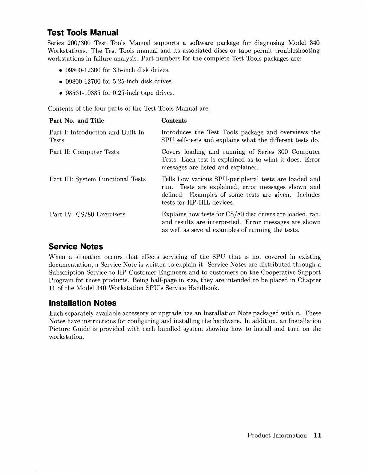
'Test
Tools Manual
Series 200/300 Test Tools Manual
supports
a software package for diagnosing Model 340
Workstations.
The
Test Tools manual
and
its associated discs
or
tape
permit
troubleshooting
workstations in failure analysis.
Part
numbers for
the
complete Test Tools packages are:
• 09800-12300 for 3.5-inch disk drives.
• 09800-12700 for 5.25-inch disk drives.
•
985~51-10835
for 0.25-inch
tape
drives.
Contents
of
the
four
parts
of
the
Test Tools Manual are:
Part
No.
and
Title
Part
I:
Introduetion
and
Built-In
Tests
Part
II:
Computer
Tests
Part
III: System Functional Tests
Part
IV: CS / 80 Exercisers
Service Notes
Contents
Introduces
the
Test Tools package
and
overviews
the
SPU
self-tests
and
explains
what
the
different
tests
do.
Covers loading
and
running
of Series 300
Computer
Tests.
Each
test
is explained as
to
what
it does.
Error
messages
are
listed
and
explained.
Tells how various
SPU-peripheral
tests
are
loaded
and
run. Tests are explained,
error
messages shown
and
defined. Examples of some
tests
are given. Includes
tests
for HP-HIL devices.
Explains how
tests
for
CS/80
disc drives
are
loaded, ran,
and
results
are
interpreted.
Error
messages are shown
as well as several examples of
running
the
tests.
When a
situation
occurs
that
effects
serVICIng
of
the
SPU
that
is
not
covered in existing
documentation,
a Service Note
is
written
to
explain it. Service Notes
are
distributed
through
a
Subscription
Service
to
HP
Customer
Engineers
and
to
customers on
the
Cooperative
Support
Program
for these products. Being half-page in size,
they
are
intended
to
be
placed in
Chapter
11
of
the
Model 340 Workstation
SPU's
Service Handbook.
Installation Notes
Each separately available accessory
or
upgrade
has
an
Installation Note packaged
with
it.
These
Notes have
instructions
for configuring
and
installing
the
hardware. In addition,
an
Installation
Picture
Guide
is
provided
with
each bundled system showing how
to
install
and
turn
on
the
workstation.
Product
Information
11
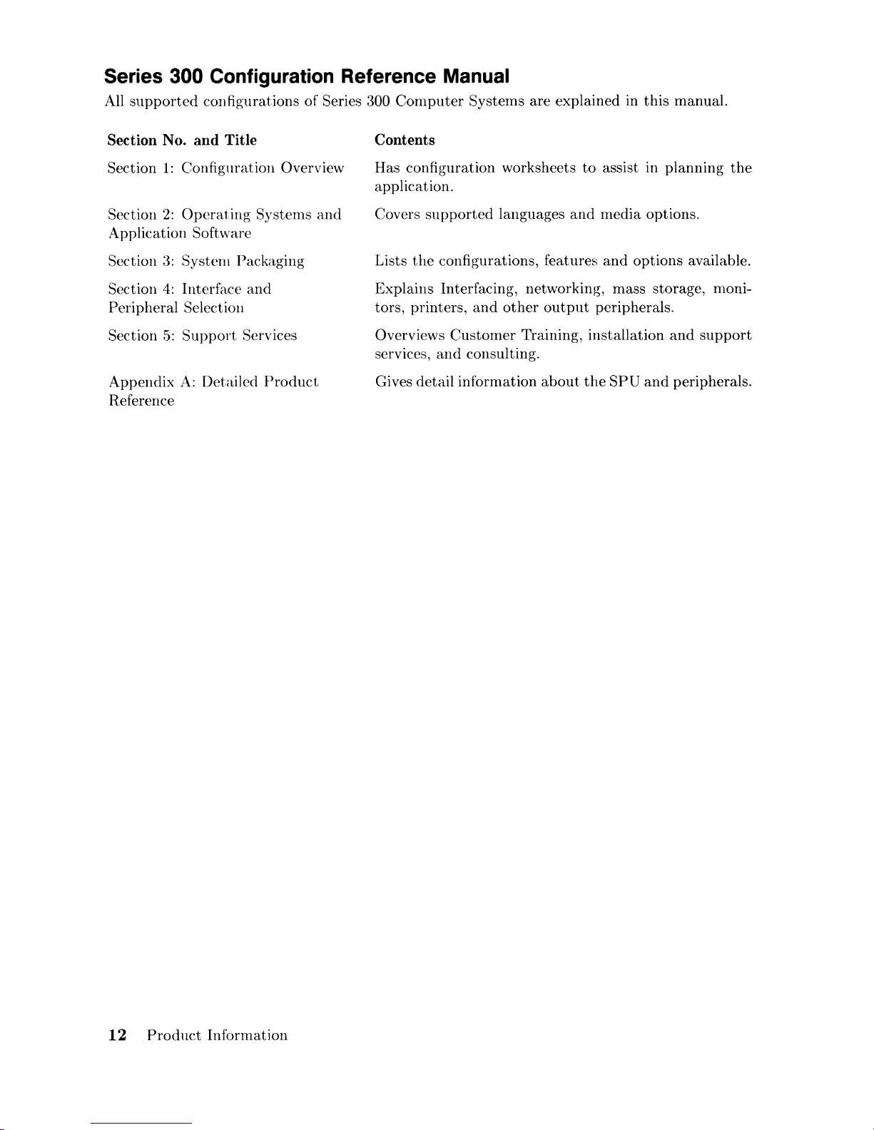
Series 300 Configuration Reference Manual
All
supported
configurations of Series 300
Computer
Systems are explained in
this
manual.
Section No. and Title
Section
1:
Configuration Overview
Section
2:
Operating
Systems
and
Application Software
Section
3:
System Packaging
Section
4:
Interface
and
Peripheral Selection
Section
5:
Support
Services
Appendix
A:
Detailed
Product
Reference
12
Product
Information
Contents
Has configuration worksheets
to
assist in planning
the
application.
Covers
supported
languages
and
media
options.
Lists
the
configurations, features
and
options
available.
Explains Interfacing, networking, mass storage, monitors, printers,
and
other
output
peripherals.
Overviews
Customer
Training, installation
and
support
services,
and
consulting.
Gives detail information
about
the
SPU
and
peripherals.
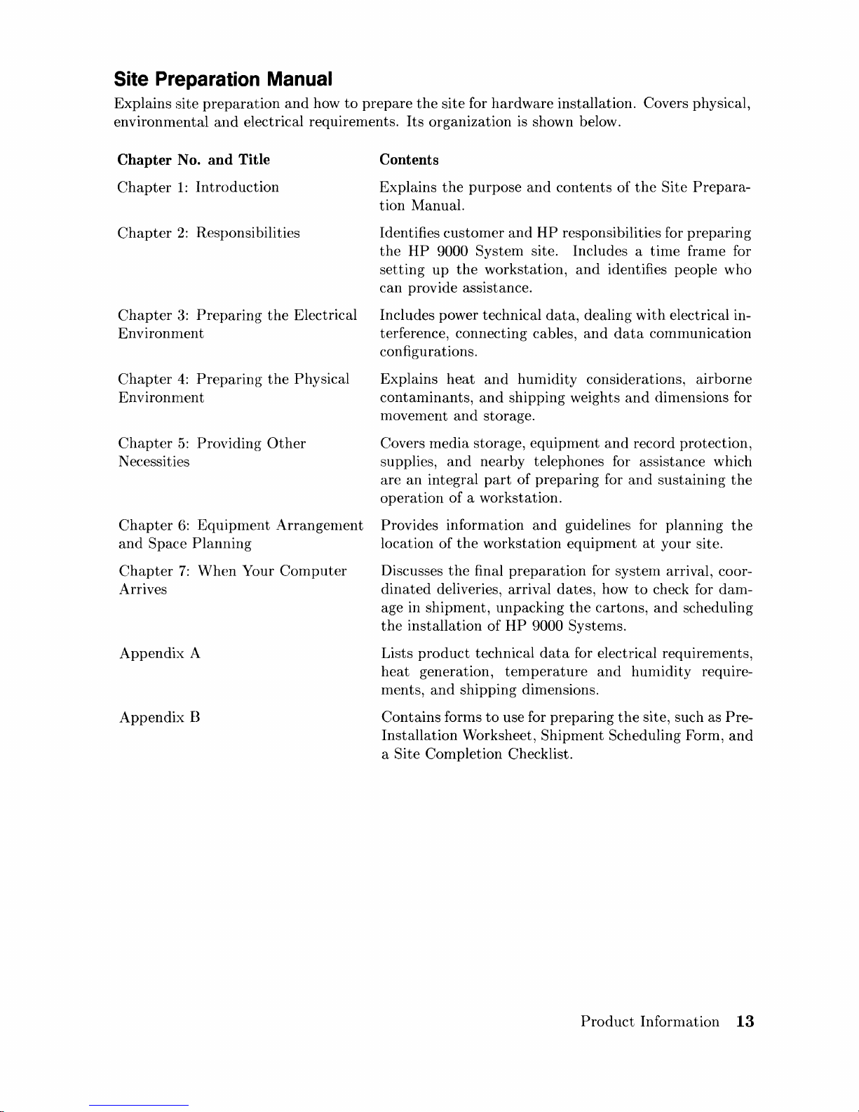
Site Preparation Manual
Explains site
preparation
and
how
to
prepare
the
site for
hardware
installation. Covers physical,
environmental
and
electrical requirements.
Its
organization is shown below.
Chapter No. and Title
Chapter
1:
Introduction
Chapter
2:
Responsibilities
Chapter
3:
Preparing
the
Electrical
Environnlent
Chapter
4:
Preparing
the
Physical
Environment
Chapter
5:
Providing
Other
Necessities
Chapter
6:
Equipment
Arrangenlent
and
Space
Planning
Chapter
7:
When
Your
Computer
Arrives
Appendix
A
Appendix
B
Contents
Explains
the
purpose
and
contents
of
the
Site
Prepara-
tion Manual.
Identifies
customer
and
HP
responsibilities for
preparing
the
HP
9000
System
site. Includes a
time
frame for
setting
up
the
workstation,
and
identifies people who
can
provide assistance.
Includes power technical
data,
dealing
with
electrical in-
terference, connecting cables,
and
data
communication
configurations.
Explains
heat
and
humidity
considerations,
airborne
contaminants,
and
shipping weights
and
dimensions for
movement
and
storage.
Covers
media
storage,
equipment
and
record protection,
supplies,
and
nearby telephones for assistance which
are
an
integral
part
of
preparing
for
and
sustaining
the
operation
of
a workstation.
Provides information
and
guidelines for planning
the
location
of
the
workstation
equipment
at
your site.
Discusses
the
final
preparation
for
system
arrival, coor-
dinated
deliveries, arrival
dates,
how
to
check for
dam-
age in shipment, unpacking
the
cartons,
and
scheduling
the
installation
of
HP
9000 Systems.
Lists
product
technical
data
for electrical requirements,
heat
generation,
temperature
and
humidity
require-
ments,
and
shipping dimensions.
Contains
forms
to
use for
preparing
the
site, such as
Pre-
Installation
Worksheet,
Shipment
Scheduling Form,
and
a Site Completion Checklist.
Product
Information
13
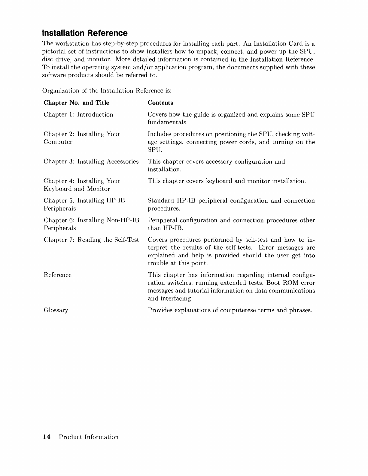
Installation Reference
The
workstation
pictorial set
disc drive,
To install
software
the
products
has
step-by-step procedures for installing each
of
instructions
and
monitor. More detailed information
operating
should
to
system
be
show installers how
and/or
referred to.
application
to
unpack, connect,
is
contained
program,
the
part.
An
Installation
and
power
in
the
Installation
docuInents supplied
Card
up
the
Reference.
with
is a
SPU,
these
Organization of
the
Installation
Chapter No. and Title
Chapter
Chapter
Computer
Chapter
Chapter
Key
Chapter
Peripherals
Chapter
Peri pherals
Chapter
board
1:
Introduction
2:
Installing Your
3:
Installing Accessories
4:
Installing Your
and
Monitor
5:
Installing
6:
Installing
7:
Reading
HP-IB
Non-HP-lB
the
Self-Test
Reference
is:
Contents
Covers how
fundamentals.
Includes procedures on positioning
age settings, connecting power cords,
SPU.
This
chapter
installation.
This
chapter
Standard
procedures.
Peripheral configuration
than
HP-IB.
Covers
terpret
explained
trou
ble
the
guide is organized
covers accessory configuration
covers keyboard
HP-IB
procedures performed by self-test
the
and
at
this
peripheral
and
results of
help is provided should
point.
the
self-tests.
and
explains some
the
SPU,
checking volt-
and
turning
and
and
rnonitor installation.
configuration
connection procedures
and
and
Error
the
connection
how
messages
user get into
SPU
on
other
to
the
in-
are
Reference
Glossary
14
Product
Infonnation
This
chapter
ration
messages
and
Provides
switches,
interfacing.
has information regarding internal configu-
running
and
tutorial
explanations
extended
information
of
COlllputerese
tests,
on
Boot
data
communications
terms
and
ROM
phrases.
error
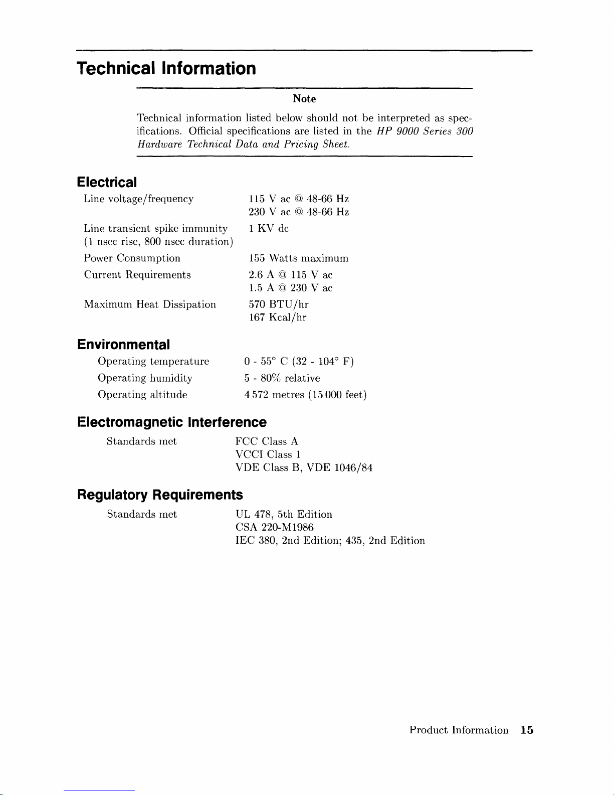
Technical Information
Note
Technical information listed below should not
ifications. Official specifications are listed in
Hardware Technical Data
Electrical
Line voltage/frequency
transient
Line
(1
nsec rise, 800 nsec duration)
spike immunity
Power Consurnption
Current
Requirements
Maximunl Heat Dissipation
I:nvironmental
Operating
Operating
Operating
telnperature
humidity
altitude
and
Pricing Sheet.
115
V ac @ 48-66
230 V ac @ 48-66
1 KV dc
155
Watts
2.6 A
1.5 A @
570
BTU/hr
167
Kcal/hr
o -55
5 -
80% relative
4572 metres
maximum
@
115
2:30
0
C (32 - 104
(15000 feet)
V ac
V ac
Hz
Hz
0
F)
be
interpreted as spec-
the
HP
9000 Series 300
Electromagnetic Interference
Standards
rnet
FCC
Class A
VCCI Class 1
VDE
Regulatory Requirements
Standards
rnet
UL 478,
CSA 220-M1986
IEC
380, 2nd Edition; 435, 2nd Edition
Class B, VDE 1046/84
5th
Edition
Product
Information
15
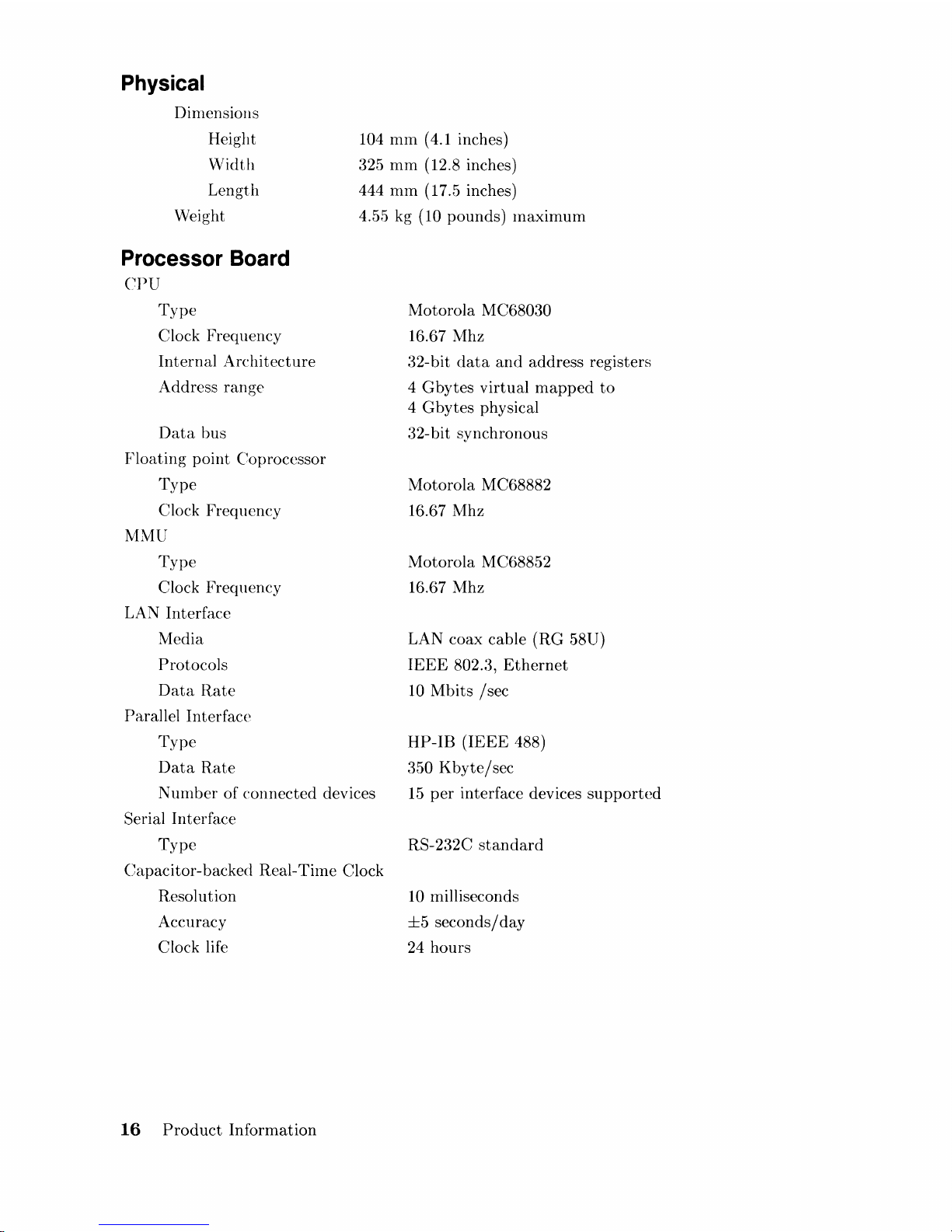
Physical
Dinlensiolls
Height
Width
Length
Weight
Processor Board
CPU
Type
Clock Frequency
Internal
Architecture
Address range
Data
bus
Floating
point Coprocessor
Type
Clock Frequency
MMU
Type
Clock Frequency
LAN Interface
Media
Protocols
Data
Rate
Parallel Interface
Type
Data
Rate
104
mm
(4.1 inches)
325
mm
(12.8 inches)
444 nlm (17.5 inches)
4.5E>
kg (10 pounds)
maximum
Motorola M C68030
16.67 Mhz
32-bit
data
and
address registers
4
Gbytes
virtual
mapped
to
4 G bytes physical
32-bit synchronous
Motorola
MC68882
16.67 Mhz
Motorola
MC68852
16.67 Mhz
LAN coax cable (RG 58U)
IEEE
802.:3,
Ethernet
10 Mbits
/sec
HP-IB
(IEEE
488)
350
Kbyte/sec
N uInber of connected devices
Serial Interface
15
per
interface devices
supported
Type
Capacitor-backed Real-
Tilne
Clock
Resolution
Accuracy
Clock life
16
Product
Information
RS-232C
standard
10
milliseconds
±5
seconds/day
24 hours
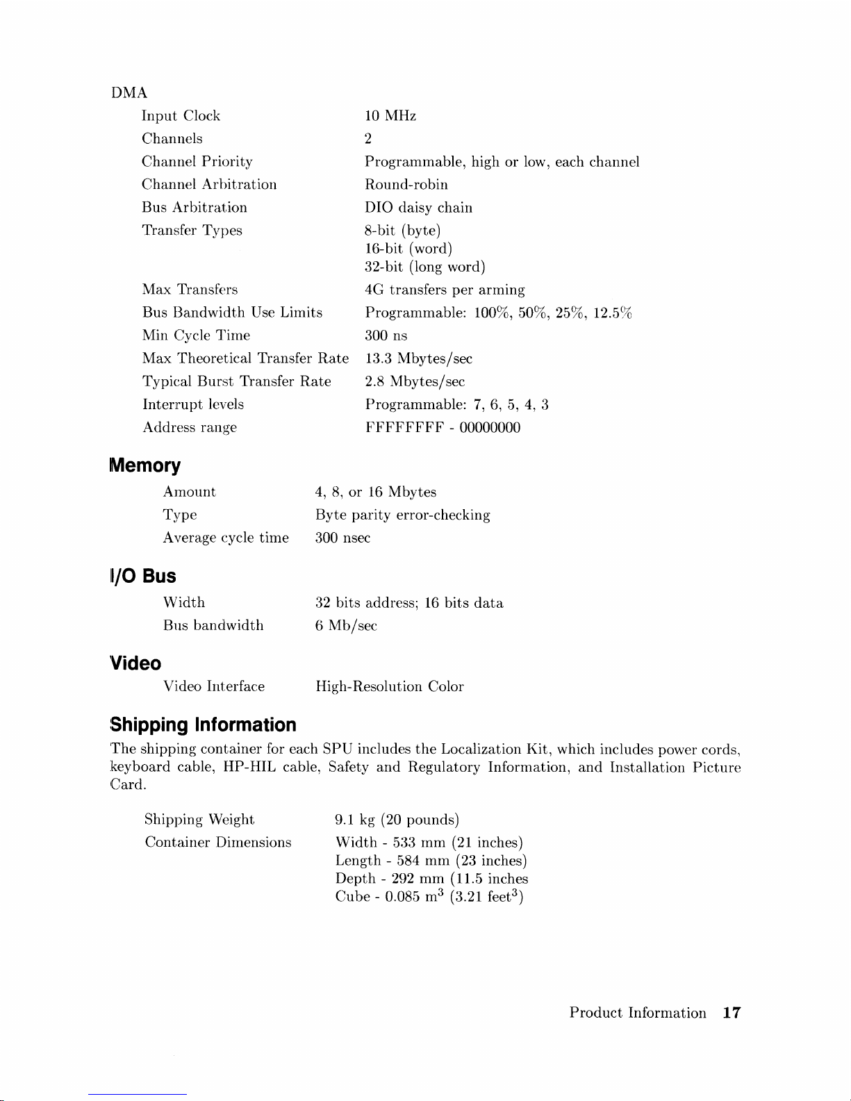
DMA
Input
Clock
Channels
10
MHz
2
Channel
Priority
Channel
Arbitration
Bus
Arbitration
Transfer
Types
ProgramlTIable, high
or
low, each channel
Round-robin
010
daisy chain
8-bit (byte)
16-bit (word)
32-bit (long word)
Max
Transfers
4G
transfers
per
arming
Bus
Bandwidth
Use Limits
Min
Cycle
Time
Programmable:
100%, 50%, 25%, 12.5%
300 ns
Max
Theoretical Transfer
Rate
Typical
Burst
Transfer
Rate
Interru
pt
levels
13.3
Mbytes/sec
2.8
Mbytes/sec
Programmable:
7,
6,
5,
4,
3
FFFFFFFF
- 00000000
Address range
Memory
A1TIolmt
Type
A verage cycle
time
11/0
Bus
Width
Bus
bandwidth
Video Interface
Shipping Information
4,
8,
or
16 Mbytes
Byte
parity
error-checking
300 nsec
32
bits
address;
16
bits
data
6
Mb/sec
High-Resolution Color
The
shipping
container
for each
SPU
includes
the
Localization Kit, which includes power cords,
keyboard cable, HP-HIL cable, Safety
and
Regulatory Information,
and
Installation
Picture
Card.
Shipping Weight
Container
Dirnensions
9.1 kg
(20 pounds)
Width
- 533 rnm
(21
inches)
Length - 584 mIn (23 inches)
Depth
- 292
mm
(11.5 inches
Cube
- 0.085 m3 (3.21 feet
3
)
Product
Information
17
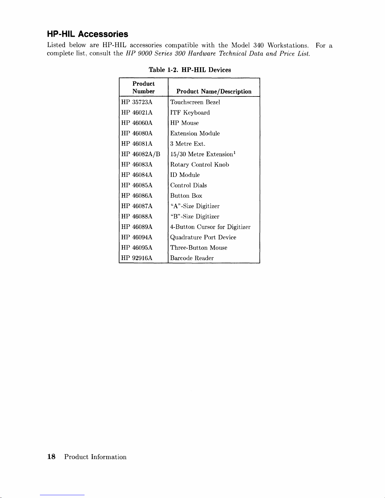
HP-HIL Accessories
Listed below are HP-HIL accessories compatible with
the
HP
complete list, consult
9000 Series 300 Hardware Technical Data
Table 1-2. HP-HIL Devices
Product
Number
HP
35723A Touchscreen Bezel
HP
46021A
HP
46060A
HP
46080A Extension Module
HP
46081A
HP
46082A/B 15/30 Metre Extension!
HP
46083A Rotary Control Knob
HP
46084A
HP
46085A
HP
46086A
HP
46087A
HP
46088A "B" -Size Digitizer
HP
46089A 4-Button Cursor for Digitizer
HP
46094A
HP
46095A Three-
HP
92916A
Product Name/Description
ITF
Keyboard
HP
Mouse
3 Metre Ext.
ID Module
Control Dials
Button
"A"
Quadrature
Barcode Reader
Box
-Size Digitizer
Port
Button
Mouse
the
Model 340 Workstations. For a
and
Price List.
Device
18
Product
Information
 Loading...