

HP 9000 330, 9000 350 Service Handbook
Service Handbook
HP 9000 Series 300 Computers
Models
330/350
HP
Part
Number 98562-90039
Flin-
HEWLETT
a!J:.
PACKARD
Hewlett-Packard
Company
3404 East
Harmony
Road, Fort Collins, Colorado 80525

ii
NOTICE
The information contained in this document is subject
to
change
without notice.
HEWLETT-PACKARD
MAKES NO WARRANTY OF ANY KIND WITH REGARD TO THIS MANUAL,
INCU
BUT
NOT
LIMITED TO, THE IMPLIED WARRANTIES
OF
MERCHANTABILITY AND FITNESS FOR A A
ULAR PURPOSE. Hewlett-Packard shall
not
be liable
for
errors contained herein
or
direct, indirect, !
incidental
or
consequential
damages
in
comection
with
the
furnishing, peI10rman0e,
or
use
of
this materi
WARRANTY
A
copy
of the specific warranty terms applicable
to
your
Hewlett-Packard product and replacement parts
obtained from
your
local Sales and Service Office.
Notices
Copyright Statement
© Copyright 1987, Hewlett-Packard Company
This document contains proprietary information which
is
protected by
copyright. All rights are reserved.
No
part
of this document may be
photocopied, reproduced, or translated to another language without
the
prior written consent of Hewlett-Packard Company. The information
contained in this document
is
subject
to
change without notice.
Restrided
Rights Legend
Use
duplication, or disclosure by the Government
is
subject
to
restric
..
tions as set forth in paragraph (b)
(3)
(B) of the Rights in Technical
Data
and Software clause in DAR 7-104.9(a).
Hewlett- Packard Company
3404 East Harmony Road, Fort Collins, Colorado
80525
Notices iii
RFI
Statement
Federal Communications Commission (U.S.A. Only)
The
Federal Communications Commission (in Subpart J of
Part
15,
Docket
20780) has specified
that
the
following notice be brought
to
the
attention of
the
users of this product.
Warning: This equipment generates, uses,
and
can radiate radio fre-
quency energy
and
if not installed
and
used in accordance with
the
instructions manual, may cause interference
to
radio communications.
It
has been tested
and
found
to
comply with
the
limits for a Class A
computing device pursuant
to
Subpart
J of
Part
15
of
FCC
Rules, which
are designed
to
provide reasonable protection against such interference
when operated in a commercial environment.
Operation of this equip-
ment in a residential area
is
likely
to
cause interference in which case
the
user
at
his own expense will be required to take whatever measures
may be required
to
correct
the
interference.
VCCI Statement
L.
O)~W!
Ii,
~-flt1HG~w!
(p.}jI~Jt!!~ICtH'
-C~ffl
~
tL
6«
~
mfG~@)
~p.}jI~Jt!!~~0).~.~m~~§~~LkmfG~9~w!~.~.~~~.~
thh~g;
(VCC!)
]t;$P:jOOi'5-L-Ci5t')i-go
ftt
-:>
-C,
tt
t
Jt!!
~
i
t::
Ii
i-
0)
~
~
L
t::
till
~ ~ ~
ffl -g 6
~,
'7
~;;f,
T v
1::"
~
3
/'
st{5m~
Ie::
stfiH~*
~l3-:z
6
L.
~
7'J{
cD
t')
i -go
IfH1H5l
B)H~ne::
ftt
-:>
-c
if
L
~'1&
t')
t&
~
,~
L
-c
F
~
~'o
iv Notices
Printing History
New editions of this manual will incorporate all material
updated
since
the
previous edition.
Update
packages may be issued between editions
and
contain replacement
and
additional pages
to
be merged into
the
mannal
by
the
user. Each
updated
page will be indicated by a revision
date
at
the
bottom
of
the
page. A vertical
bar
in
the
margin indicates
the changes on each page. Note
that
pages which are rearranged due
to
changes on a previous page are
not
considered revised.
The
manual printing
date
and
part
number indicate its current edition.
The
printing
date
changes when a new edition
is
printed. (Minor cor-
rections
and
updates
which are incorporated
at
reprint do
not
cause
the
date
to
change.)
The
manual
part
number
changes when extensive
technical changes are incorporated.
February 1987 ... Edition 1
Notices v
Safety Considerations
WARNINGs, CAUTIONs, and Notes
WARNINGS, CAUTIONS
and
Notes are used in this manual
to
alert
users
to
important
situations.
They
are used as follows:
• WARNINGS contain information which, if not observed, could result in injury
to
personnel or loss of life.
• CAUTIONS contain information which if not observed, could result in damage
to
or
destruction of equipment.
• Notes contain information
that
will assist you in accomplishing
the
job.
WARNING
The power supply is hazardous to personnel. Extreme care must be taken when connecting voltmeter probes to the test points. Turn off the unit
and remove the power cord before connecting or
removing test probes.
CAUTION
Integrated circuits on PC boards are susceptible
to damage
by
electro-static discharge. Extreme
care must be taken when handling printed circuit
boards.
Use an Anti-static Workstation.
Note
Hewlett-Packard supports field repair of these
products only
to
the
board
or assembly level.
Component level information and repair
is
not
within
the
scope of this manuaL nor available.
vi Notices
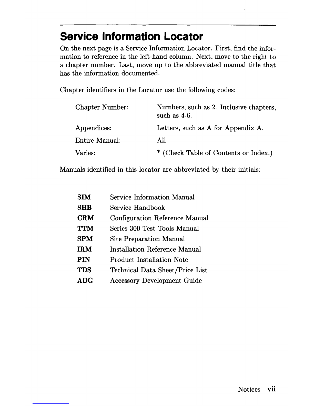
Service Information Locator
On
the
next page
is
a Service Information Locator. First, find
the
infor-
mation
to
reference in the left-hand column. Next, move
to
the
right
to
a chapter number. Last, move
up
to
the
abbreviated manual title
that
has
the
information documented.
Chapter
identifiers in the Locator use
the
following codes:
Chapter
Number: Numbers, such as
2.
Inclusive chapters,
such as
4-6.
Appendices: Letters, such as A for Appendix A.
All Entire Manual:
Varies: * (Check Table of Contents
or
Index.)
Manuals identified in this locator are abbreviated by their initials:
81M
8HB
CRM
TTM
8PM
IRM
PIN
TD8
ADG
Service Information Manual
Service Handbook
Configuration Reference Manual
Series 300 Test Tools Manual
Site
Preparation
Manual
Installation Reference Manual
Product
Installation Note
Technical
Data
Sheet/Price List
Accessory Development Guide
Notices vii
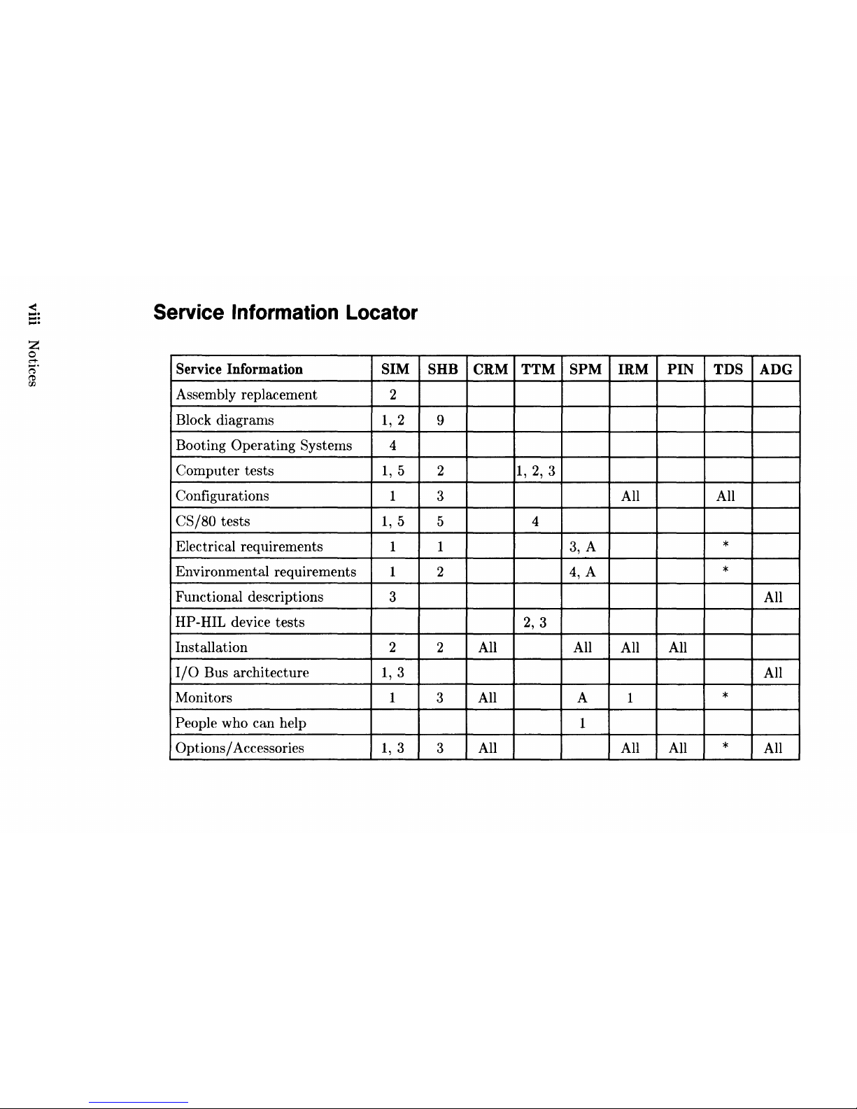
Service Information Locator
Service Information
SIM SHB
CRM
TTM
SPM
IRM
PIN
TDS
ADG
Assembly replacement
2
Block diagrams
1,2
9
Booting Operating Systems 4
Computer tests
1,5
2
1,2,3
Configurations
1
3 All All
CS/80
tests
1,5
5
4
Electrical requirements
1 1
3,
A
*
Environmental requirements
1 2
4,
A
*
Functional descriptions
3
All
HP
-HIL device tests
2,
3
Installation
2 2 All All
All
All
I/O
Bus architecture
1,3
All
Monitors
1
3
All A
1
*
People who can help
1
Options/
Accessories
1,
3
3
All All All
*
All
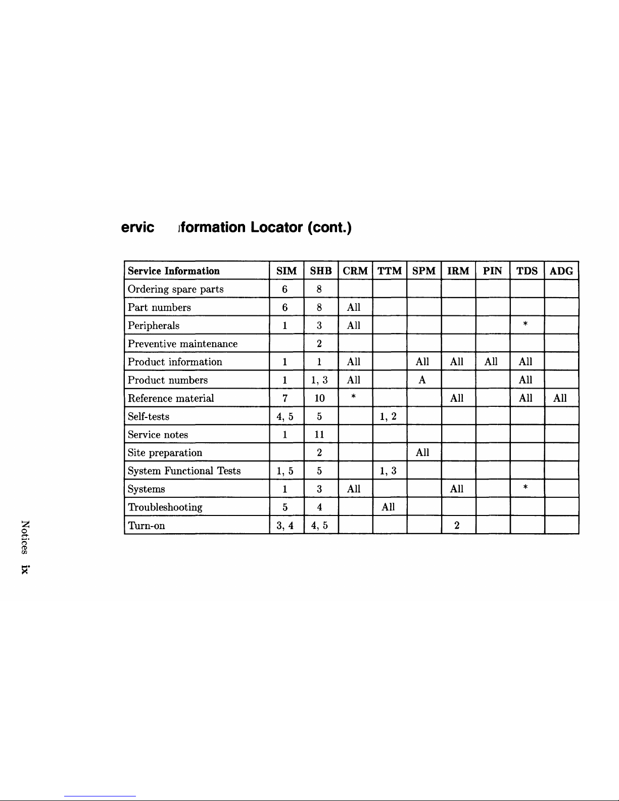
ervic
Jformation
Locator (cont.)
Service Information SIM SHB CRM TTM
SPM
IRM
PIN
TDS
ADG
Ordering spare
parts
6 8
Part
numbers
6
8
All
Peripherals 1 3
All
*
Preventive maintenance
2
Product
information 1
1
All
All All
All
All
Product
numbers 1
1,3
All
A
All
Reference material
7
10
*
All
All
All
Self-tests
4,
5
5
1,2
Service notes 1
11
Site preparation 2
All
System Functional Tests
1,5
5
1,3
Systems 1 3
All
All
*
Troubleshooting
5
4
All
Turn-on 3, 4
4,
5 2
><.
Table of Contents
Chapter
1
Product
Information
Introduction. . . . . . . . . . . . . . . . . . . . . . . . . . . . . . . . . . . . . . . . . . .
..
1
Hewlett-Packard
Support
.................................
1
Repair Philosophy
...................................
1
Repair Services . . . . . . . . . . . . . . . . . . . . . . . . . . . . . . . . . . . .
..
2
Hardware
Support
Services. . . . . . . . . . . . . . . . . . . . . . . . . .
..
3
Operating Systems
Support
.........................
" 3
System Features . . . . . . . . . . . . . . . . . . . . . . . . . . . . . . . . . . . . . . .
..
5
Computers
..........................................
5
Expanders
..........................................
6
Serial Numbers . . . . . . . . . . . . . . . . . . . . . . . . . . . . . . . . . . . .
..
6
Specifications. . . . . . . . . . . . . . . . . . . . . . . . . . . . . . . . . . . . . . . . . .
..
7
Electrical
...........................................
7
Environmental. . . . . . . . . . . . . . . . . . . . . . . . . . . . . . . . . . . . .
..
8
Electromagnetic Interference
..........................
8
Regulatory Requirements
.............................
8
Physical.
. . . . . . . . . . . . . . . . . . . . . . . . . . . . . . . . . . . . . . . . .
..
8
Shipping
Information.
. . . . . . . . . . . . . . . . . . . . . . . . . . . . . .
..
9
Model 350 Processor Board
..........................
10
Model 330 Processor Board
..........................
11
Memory
...........................................
12
DIO-II
I/O
Bus.
. . . . . . . . . . . . . . . . . . . . . . . . . . . . . . . . . .
..
12
System Interface
Board.
. . . . . . . . . . . . . . . . . . . . . . . . . . .
..
13
HP
-HIL
and
Video Accessories
.......................
14
Monitors. . . . . . . . . . . . . . . . . . . . . . . . . . . . . . . . . . . . . . . . .
..
15
Operating Systems . . . . . . . . . . . . . . . . . . . . . . . . . . . . . . . .
..
16
Rack Mount Kits
...................................
17
Standard
Tools . . . . . . . . . . . . . . . . . . . . . . . . . . . . . . . . . . . . . . .
..
18
Computer/System
Tests
.............................
18
Chapter
2
Environmental/Installation/PM
Environmental. . . . . . . . . . . . . . . . . . . . . . . . . . . . . . . . . . . . . . . .
..
19
Environmental Specifications
.......................
" 19
Electromagnetic Interference
.........................
19
x Table of Contents
Regulatory
Requirements.
. . . . . . . . . . . . . . . . . . . . . . . . .
..
19
Physical
...........................................
20
Shipping Information . . . . . . . . . . . . . . . . . . . . . . . . . . . . . .
..
20
Installation. . . . . . . . . . . . . . . . . . . . . . . . . . . . . . . . . . . . . . . . . . .
..
21
Mounting.
. . . . . . . . . . . . . . . . . . . . . . . . . . . . . . . . . . . . . . .
..
21
Cabling
............................................
21
Preventive Maintenance. . . . . . . . . . . . . . . . . . . . . . . . . . . . . . . .
..
22
Chapter
3
Configuration
Bundled Systems
.......................................
23
Supported Configurations . . . . . . . . . . . . . . . . . . . . . . . . . . . . . .
..
23
Board Installation Precautions. . . . . . . . . . . . . . . . . . . . . . . . . .
..
24
RAM Configuration . . . . . . . . . . . . . . . . . . . . . . . . . . . . . . . . . . .
..
25
RAM Configuration Examples . . . . . . . . . . . . . . . . . . . . . .
..
26
System Interface Board . . . . . . . . . . . . . . . . . . . . . . . . . . . . . . . .
..
27
HP-IB
and
RS-232 Switches. . . . . . . . . . . . . . . . . . . . . . . .
..
27
High-Speed Disc Add-On
Switches.
. . . . . . . . . . . . . . . . .
..
28
LAN
Switches.
. . . . . . . . . . . . . . . . . . . . . . . . . . . . . . . . . . .
..
29
Accessories . . . . . . . . . . . . . . . . . . . . . . . . . . . . . . . . . . . . . . . . . . .
..
30
Supported Accessory
Boards/Cards.
. . . . . . . . . . . . . . . .
..
30
HP-HIL Accessories. . . . . . . . . . . . . . . . . . . . . . . . . . . . . . .
..
33
Chapter
4
Troubleshooting
Initial Troubleshooting
Flowchart.
. . . . . . . . . . . . . . . . . . . . . .
..
36
Dead Unit Troubleshooting
Flowchart.
. . . . . . . . . . . . . . . . . .
..
37
Live Unit Troubleshooting
Flowchart.
. . . . . . . . . . . . . . . . . . .
..
38
Power Supply Specifications . . . . . . . . . . . . . . . . . . . . . . . . . . . .
..
39
Voltage Indicators. . . . . . . . . . . . . . . . . . . . . . . . . . . . . . . . .
..
39
General Failure Indications. . . . . . . . . . . . . . . . . . . . . . . . .
..
40
Boot
ROM
Error Codes
.............................
41
Remote Computer Analysis
..............................
43
Locating Defective
RAM.
. . . . . . . . . . . . . . . . . . . . . . . . . .
..
43
Boot ROM Self-Tests. . . . . . . . . . . . . . . . . . . . . . . . . . . . . . . . . .
..
44
Error Codes . . . . . . . . . . . . . . . . . . . . . . . . . . . . . . . . . . . . . .
..
45
Chapter
5
Computer Tests
Test Tools
.............................................
47
Table of Contents xi
Chapter
6
Adjustments
...............................................
49
Chapter
7
Peripherals
Supported
Peripherals
List.
. . . . . . . . . . . . . . . . . . . . . . . . . . . .
..
51
Chapter
8
Parts
Lists
Replacement
Parts
Information . . . . . . . . . . . . . . . . . . . . . . . . .
..
53
Introduction.
. . . . . . . . . . . . . . . . . . . . . . . . . . . . . . . . . . . . .
..
53
Cooperative
Support
Program
. . . . . . . . . . . . . . . . . . . . . .
..
54
Exchange
Parts
. . . . . . . . . . . . . . . . . . . . . . . . . . . . . . . . . . .
..
54
Part
Number Lists . . . . . . . . . . . . . . . . . . . . . . . . . . . . . . . . . . . .
..
55
Static-Free Bags . . . . . . . . . . . . . . . . . . . . . . . . . . . . . . . . . .
..
55
Labels
.............................................
55
Computer
Electrical
Parts
...........................
56
Computer
Case
Parts.
. . . . . . . . . . . . . . . . . . . . . . . . . . . . .
..
58
Expander
Case
Parts
Diagram.
. . . . . . . . . . . . . . . . . . . . .
..
60
HP
98570A
and
98568A
Opt.
132
Expander.
. . . . . . . . .
..
61
Printed
Circuit Boards
..............................
63
Miscellaneous Electrical
Parts
........................
63
External
Cables. . . . . . . . . . . . . . . . . . . . . . . . . . . . . . . . . . .
..
63
HP-HIL
Devices.
. . . . . . . . . . . . . . . . . . . . . . . . . . . . . . . . .
..
64
Chapter
9
Diagrams
Model 330/350
Computer.
. . . . . . . . . . . . . . . . . . . . . . . . . . . . .
..
65
Computer
Block Diagram . . . . . . . . . . . . . . . . . . . . . . . . . .
..
65
Power Supply
......................................
66
Power
Distribution.
. . . . . . . . . . . . . . . . . . . . . . . . . . . . . . .
..
67
Model 330 Processor Board
..........................
68
Model 350 Processor Board
..........................
69
RAM Boards . . . . . . . . . . . . . . . . . . . . . . . . . . . . . . . . . . . . .
..
70
System Interface Board . . . . . . . . . . . . . . . . . . . . . . . . . . . .
..
71
Video
Boards.
. . . . . . . . . . . . . . . . . . . . . . . . . . . . . . . . . . . .
..
72
Expanders
.............................................
73
Power Supply
......................................
73
Power Distribution . . . . . . . . . . . . . . . . . . . . . . . . . . . . . . . .
..
74
xii
Table of Contents

Chapter 10
Reference
Hardware Support Documentation . . . . . . . . . . . . . . . . . . . . . .
..
75
Installation Manuals/Notes. . . . . . . . . . . . . . . . . . . . . . . . . . . . .
..
76
Chapter
11
Service Notes. . . . . . . . . . . . . . . . . . . . . . . . . . . . . . . . . . . . . . . . . . . . .
..
77
Table of Contents xiii

Product Information
1
Introduction
Information in this handbook refers
to
the
HP
9000 Series 300
~1odel
330
and
350
~omputers.
These computers are
product
numbers
HP
98562A
and
HP
98562B, respectively
Where applicable,
the
information also applies
to
the
HP
98568A
Opt.
132
and
HP
98570A Direct-Connect
System/DIO
Slot Expanders.
Hewlett-Packard Support
Support
services
and
policies mentioned in this section are subject
to
change. Please consult your local Hewlett-Packard Sales
and
Service
Office for
the
current
support
policies.
Repair Philosophy
Field Repair Philosophy for
the
Model 330/350
Computers
and
the
HP
98568A
Opt.
132
and
98570A Expanders
is
assembly,
or
board
level.
This means
that
when a failure occurs,
the
problem is diagnosed
to
the
assembly having
the
failed
part.
That
assembly is
then
replaced.
Replacement assemblies are available
through
local
HP
Sales
and
Service
Offices.
Some assemblies may be exchanged for rebuilt ones.
Other
assemblies
are only available as new ones. Refer
to
Chapter
6, or
the
Service Hand-
book,
Chapter
8,
for information on replacement
parts.
Schematics
In
support
of
the
repair philosophy, this manual contains information
to
the
assembly level. Schematics are
not
available for these products.
Product
Information 1
Supported Configurations
Only computer systems with Hewlett-Packard approved parts, accessories, peripherals, operating systems
and
application programs are sup-
ported
by Hewlett-Packard. Any computer system with other
than
HP
approved hardware
or
software connected
or
installed must have
the
non-HP approved hardware
and
software removed by
the
customer be-
fore On-Site or Service Center repair
is
accomplished.
Refer
to
the
Series 300 Configuration Reference Manual (98561-90020)
for
supported
hardware/software products
and
combinations thereof.
Repair Services
Hewlett-Packard provides repair services in three ways:
• On-Site Repair.
• Service Center Repair.
• Customer Repair.
On-Site Repair
For On-Site Repair,
an
HP
Customer Engineer goes
to
the
customers
site, troubleshoots,
and
repairs
the
hardware
to
the assembly level.
The
defective assembly
is
replaced
with
a new or rebuilt assembly. This
service
is
available through a service contract
or
a time-and-materials
basis.
Hewlett-Packard Service Center Repair
The
customer returns
the
defective product to the nearest
HP
Repair
Center. An
HP
Customer Engineer repairs
the
product
to
the
assembly
level in the same manner as On-Site Repair. Upon being repaired,
the
product
is
returned
to
the
customer. Contact your nearest
HP
Sales
and
Service Office for
the
location of the
HP
Repair Center, typical
turn-around
times,
and
shipping instructions.
2
Product
Information
Customer
Repair
Customers have
the
option of repairing their own
HP
computer prod-
ucts. Contact your nearest
HP
Sales and Service Office for information
concerning service training, special tools and
test
equipment,
and
spare
parts.
Hewlett-Packard offers a Customer Cooperative Support
Program
to
assist customers in maintaining their
HP
computer products. A variety
of technical services and information are available. Your local
HP
Sales
and
Service can provide you with information
about
the
Cooperative
Support Program.
Hardware Support Services
There are many hardware
support
options available, from utilizing on-
site maintenance groups
to
buying full
support
from the local sales office.
Please contact your local Hewlett-Packard Sales
and
Service Office for
these services.
Operating Systems Support
Primary
Support
There are numerous operating system
support
options:
• Account Management Support (AMS) provides a local SE, onsite assistance, one Response Center caller
and
one alternate for
telephone assistance,
and
a Software Materials Subscription.
• Response Center
Support
(RCS) provides one Response Center
caller
and
one alternate for telephone assistance,
and
Software Ma-
terials Subscription.
• Software Materials Subscription (SMS) provides software
and
man-
ual updates, Software
Status
Bulletins,
and
HP
communicator
magazine. Updates
to
ROM-based systems are not provided.
Product
Information 3
Support For
An
Additional System
The
following options
support
an
additional system:
• Additional System Coverage extends AMS or RCS coverage on
the
operating system
to
one additional system
under
the
same system
manager.
All
support
is delivered through
the
central system.
•
Extended
Materials
Support
extends SMS by providing
the
right
to
make one copy of all central system materials for use on one
additional system.
• Additional Response Center Caller provides one additional caller
and
one
alternate
for access
to
the
HP Response Center
• Manual
Update
Service (MUS) provides one copy of
updates
to
software reference manuals.
• Software Notification Service (SNS) provides issues of
the
HP Com-
municator
and
Software
Status
Bulletin.
4
Product
Information
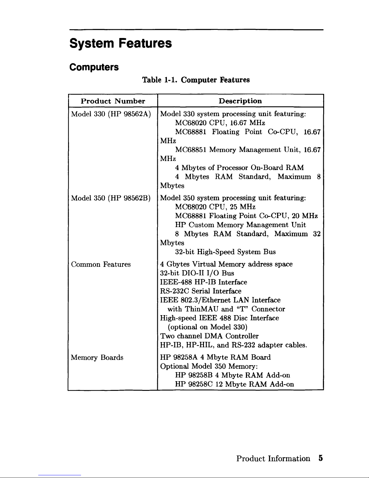
System Features
Computers
Table 1-1. Computer Features
Product
Number
Description
Model 330 (HP 98562A) Model 330 system processing
unit
featuring:
MC68020 CPU, 16.67 MHz
MC68881 Floating
Point Co-CPU, 16.67
MHz
MC68851 Memory Management Unit, 16.67
MHz
4 Mbytes of Processor On-Board RAM
4 Mbytes RAM Standard, Maximum 8
Mbytes
Model
350
(HP
98562B) Model 350 system processing
unit
featuring:
MC68020 CPU,
25
MHz
M C68881 Floating
Point Co-CPU, 20 MHz
HP
Custom
Memory Management
Unit
8 Mbytes RAM Standard, Maximum 32
Mbytes
32-bit High-Speed System Bus
Common Features 4 Gbytes
Virtual
Memory address space
32-bit DIO-II
I/O
Bus
IEEE-488
HP
-IB Interface
RS-232C Serial Interface
IEEE
802.3/Ethernet
LAN Interface
with ThinMAU
and
"T" Connector
High-speed
IEEE
488 Disc Interface
(optional on Model
330)
Two channel DMA Controller
HP-IB, HP-HIL,
and
RS-232
adapter
cables.
Memory Boards
HP
98258A 4 Mbyte RAM Board
Optional Model
350 Memory:
HP
98258B 4 Mbyte RAM Add-on
HP
98258C
12
Mbyte RAM Add-on
Product
Information 5
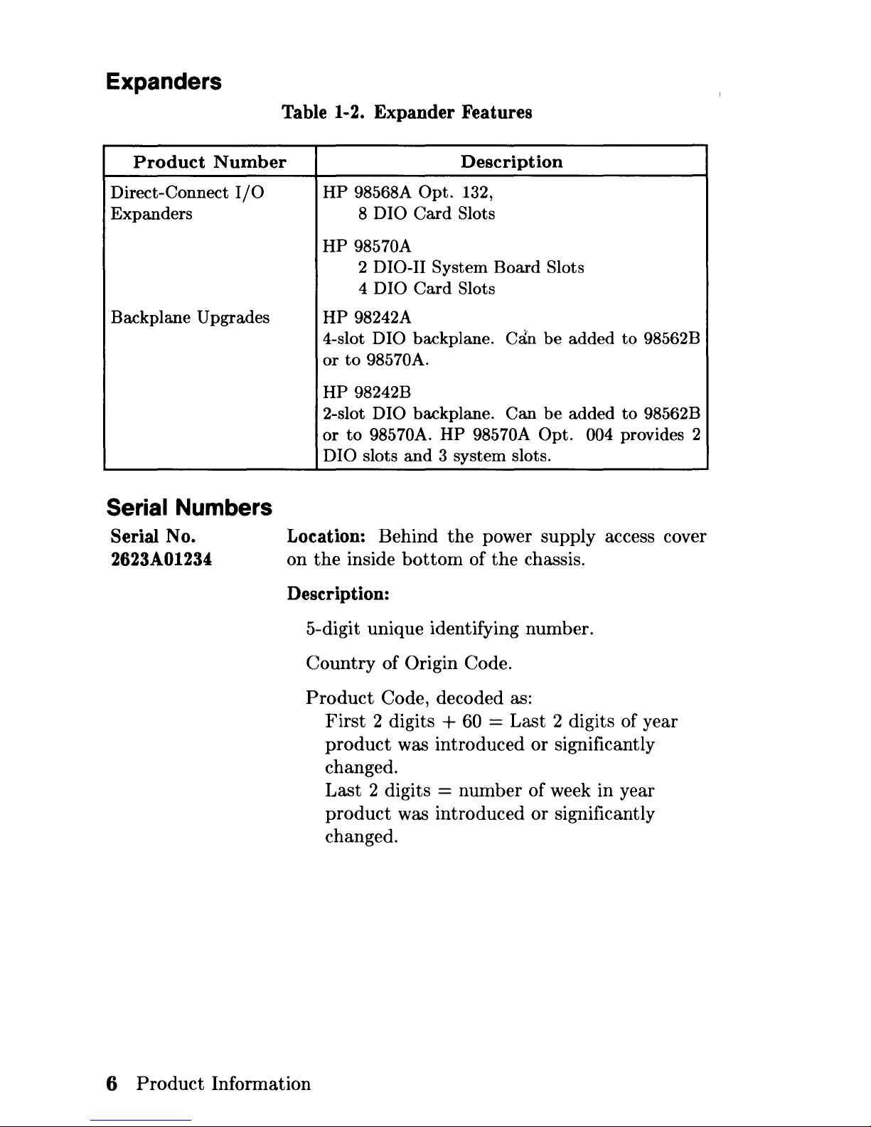
Expanders
Table 1-2. Expander Features
Product
Number
Direct-Connect
I/O
Expanders
Backplane Upgrades
Serial Numbers
Serial No.
2623A01234
Description
HP
98568A
Opt.
132,
8 D I
0
Card
Slots
HP
98570A
2 DIO-II System
Board
Slots
4 DIO
Card
Slots
HP
98242A
4-slot
DIO backplane.
Ccln
be
added
to
98562B
or
to
98570A.
HP
98242B
2-slot
DIO backplane.
Can
be
added
to
98562B
or
to
98570A.
HP
98570A
Opt.
004 provides 2
DIO
slots
and
3 system slots.
Location: Behind
the
power supply access cover
on
the
inside
bottom
of
the
chassis.
Description:
5-digit unique identifying number.
Country
of Origin Code.
Product
Code, decoded as:
First
2 digits + 60 = Last 2 digits of year
product
was introduced or significantly
changed.
Last 2 digits = number of week in year
product
was introduced or significantly
changed.
6
Product
Information
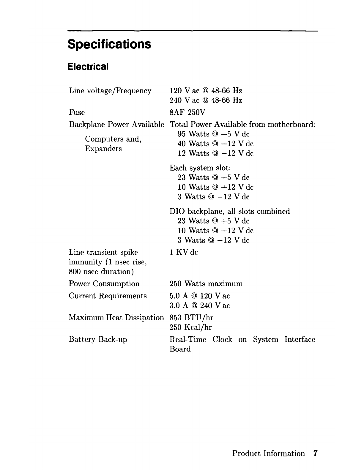
Specifications
Electrical
Line voltage/Frequency
120
Vac
@ 48-66
Hz
240 V ac @ 48-66
Hz
Fuse 8AF 250V
Backplane Power Available Total Power Available from motherboard:
Computers and,
Expanders
Line transient spike
immunity
(1
nsec rise,
800 nsec duration)
Power Consumption
Current Requirements
Maximum Heat Dissipation
Battery
Back-up
95
Watts @
+5
V dc
40 Watts @
+12
V dc
12
Watts @
-12
V dc
Each system slot:
23
Watts @
+5
V dc
10
Watts @
+12
V dc
3 Watts @
-12
V dc
DIO backplan.e, all slots combined
23
Watts @
+5
V dc
10
Watts @
+12
V dc
3 Watts @
-12
V dc
1
KVdc
250
Watts
maximum
5.0 A @ 120 V ac
3.0 A @ 240 V ac
853
BTU/hr
250
Kcal/hr
Real-Time Clock on System Interface
Board
Product
Information 7
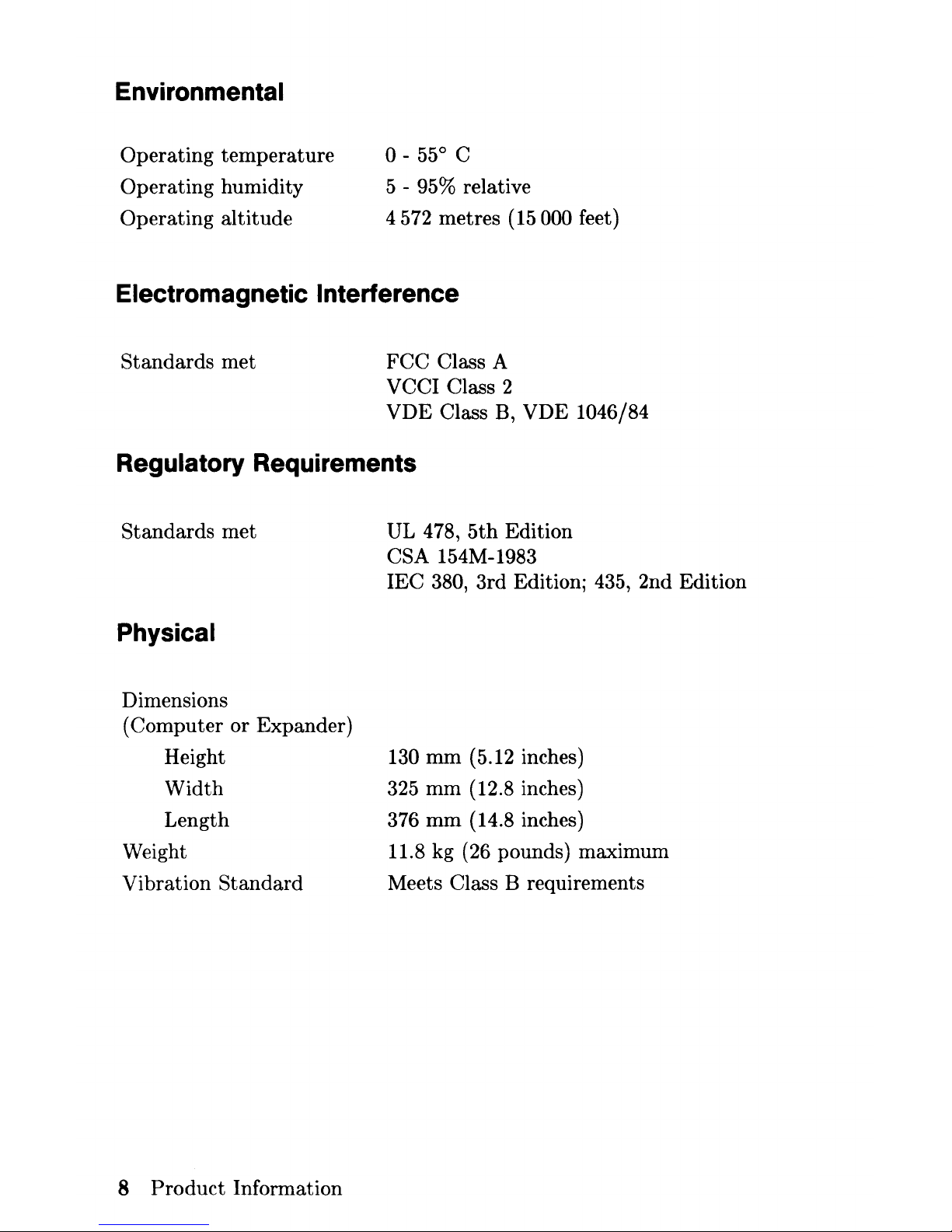
Environmental
Operating temperature
Operating humidity
Operating altitude
0-
55° C
5 - 95% relative
4 572 metres
(15
000 feet)
Electromagnetic Interference
Standards met
FCC
Class A
VCCI Class 2
VDE
Class B, VDE 1046/84
Regulatory Requirements
Standards
met
Physical
Dimensions
(Computer or Expander)
UL
478,
5th
Edition
CSA 154M-1983
lEC
380, 3rd Edition; 435, 2nd Edition
Height
130
mm
(5.12 inches)
Width
325
mm
(12.8 inches)
Length 376
mm
(14.8 inches)
Weight 11.8 kg (26 pounds) maximum
Vibration
Standard
Meets Class B requirements
8
Product
Information
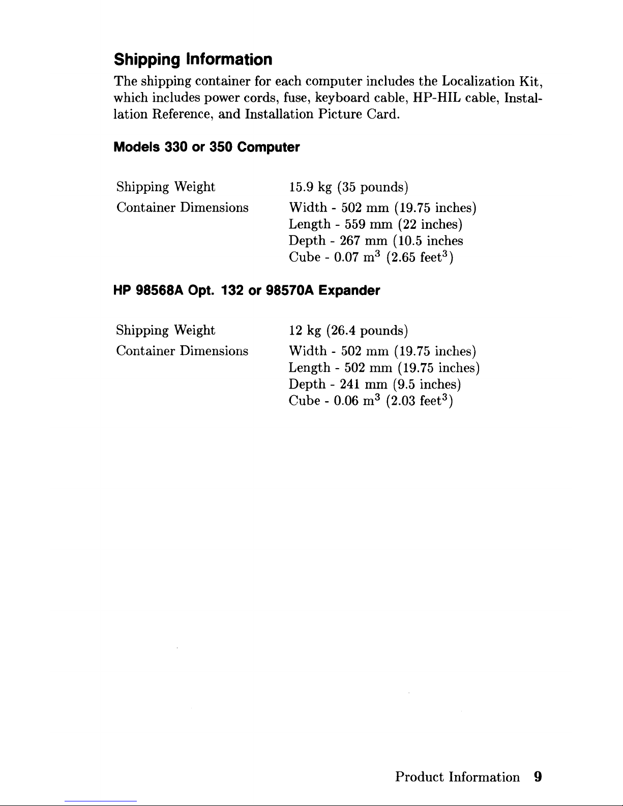
Shipping
Information
The
shipping container for each computer includes the Localization Kit,
which includes power cords, fuse, keyboard cable, HP-HIL cable, Installation Reference,
and
Installation
Picture
Card.
Models 330 or 350 Computer
Shipping Weight
Container Dimensions
15.9 kg
(35
pounds)
Width
- 502
mm
(19.75 inches)
Length - 559
mm
(22
inches)
Depth
- 267
mm
(10.5 inches
Cube - 0.07 m3 (2.65 feet
3
)
HP
98568A Opt. 132 or 98570A Expander
Shipping Weight
Container Dimensions
12
kg (26.4 pounds)
Width -502
mm
(19.75 inches)
Length - 502
mm
(19.75 inches)
Depth -241
mm
(9.5 inches)
Cube - 0.06 m3 (2.03 feet
3
)
Product
Information 9

Model 350 Processor Board
CPU
Floating
Point
Co-CPU
Memory Management
Type
Virtual
Memory
Contexts
Page size
Cache Memory
Type
RAM
Cycle time
Partitioning
Timers
Match
interrupt
Delay
interrupt
Cyclical
interrupt
System
Timer
Beeper
Frequency range
Resolution
Duration
10
Product
Information
MC68020
at
25
MHz
MC68881
at
20
MHz
HP
Custom
MMU
4 G bytes
per
process
84 default, user settable
4
Kbytes/page
Write through, instruction,
data
(external
to
M C68020 instruction cache)
16 Kbytes, 8K words of 32-bit entries
120 nsec
Four 32-bit words each; 2K partitions
Match
on time of day 0.00 - 86 400.00 sec-
onds
10 msec - 1.94 days
10
msec - 1.94 days
4
Jisec resolution, accurate
to
25
ppm
Three
independent tone generators con-
trollable over
30 db.
81.46 Hz - 8.33 KHz
Capable of approximate tone scale over 5
octaves
0.01 second to 2.55 seconds per tone
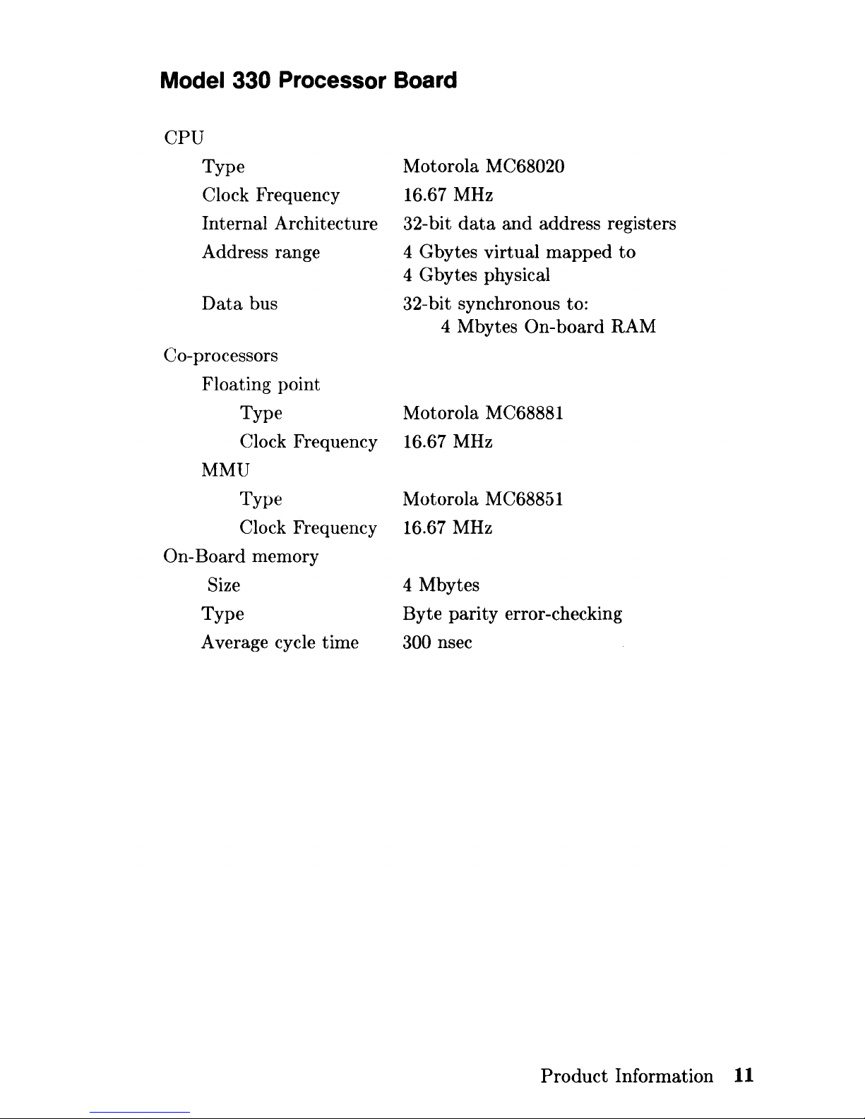
Model 330 Processor Board
CPU
Type
Clock Frequency
Internal Architecture
Address range
Data
bus
Co-processors
Floating point
Type
Clock Frequency
MMU
Type
Clock Frequency
On-Board memory
Size
Type
Average cycle time
Motorola
MC68020
16.67 MHz
32-bit
data
and
address registers
4 Gbytes virtual
mapped
to
4 Gbytes physical
32-bit synchronous to:
4 Mbytes
On-board
RAM
Motorola MC68881
16.67 MHz
Motorola MC68851
16.67 MHz
4 Mbytes
Byte
parity
error-checking
300 nsec
Product
Information
11
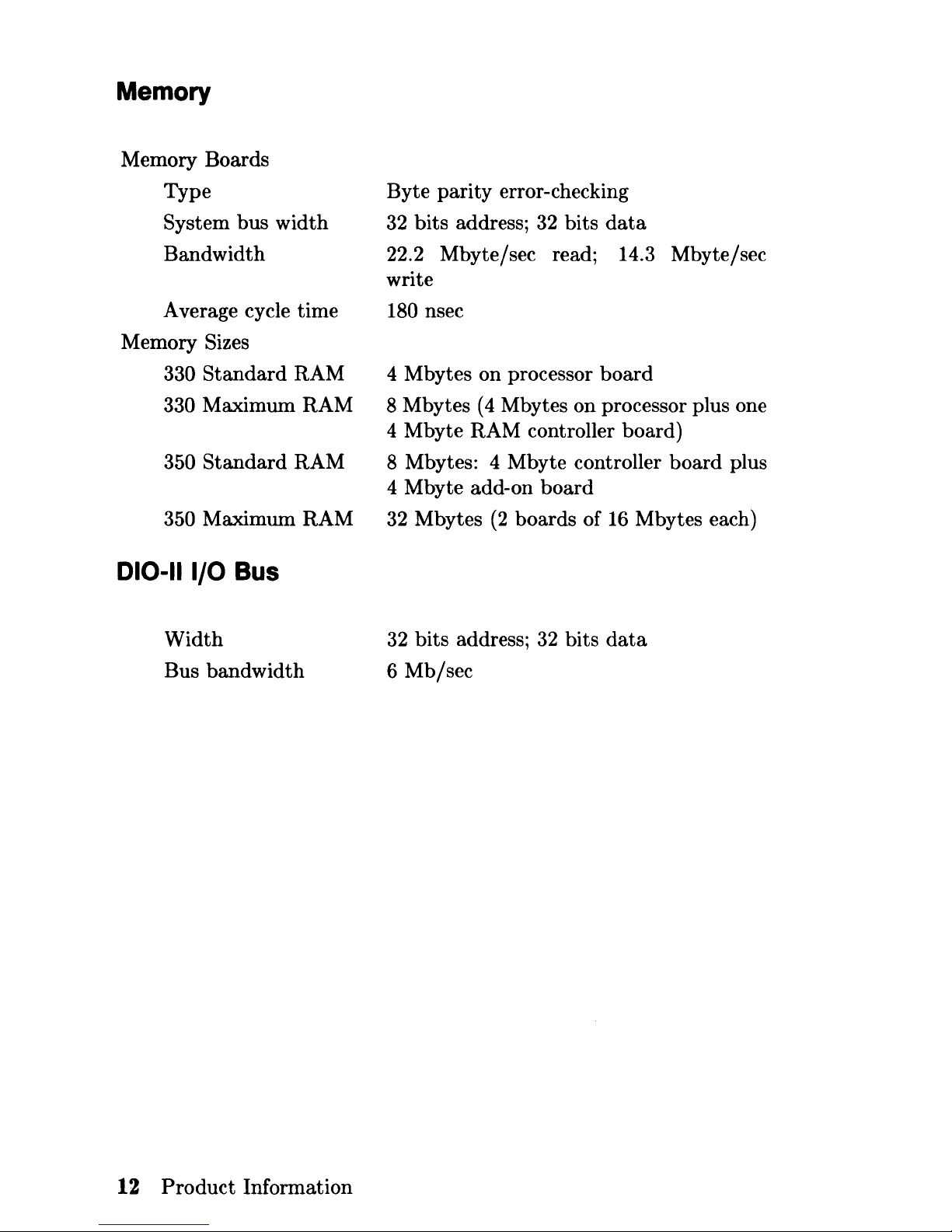
Memory
Memory Boards
Type
System bus width
Bandwidth
Average cycle time
Memory
Sizes
330
Standard
RAM
330 Maximum RAM
350
Standard
RAM
350 Maximum RAM
010-11
1/0
Bus
Width
Bus bandwidth
12
Product
Information
Byte parity error-checking
32
bits address;
32
bits
data
22.2 Mbyte/sec read; 14.3 Mbyte/sec
write
180 nsec
4 Mbytes on processor
board
8 Mbytes
(4
Mbytes on processor plus one
4 Mbyte RAM controller board)
8 Mbytes: 4 Mbyte controller board plus
4 Mbyte add-on board
32
Mbytes
(2
boards of
16
Mbytes each)
32
bits address;
32
bits
data
6 Mb/sec
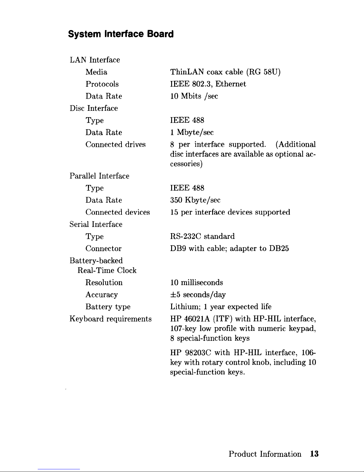
System Interface Board
LAN Interface
Media
Protocols
Data
Rate
Disc Interface
Type
Data
Rate
Connected drives
Parallel Interface
Type
Data
Rate
Connected devices
Serial Interface
Type
Connector
Battery-backed
Real-Time Clock
Resolution
Accuracy
Battery
type
Keyboard requirements
ThinLAN coax cable (RG 58U)
IEEE
802.3,
Ethernet
10 Mbits /sec
IEEE
488
1 Mbyte/sec
8
per
interface supported. (Additional
disc interfaces are available as optional accessories)
IEEE
488
350 Kbyte / sec
15
per
interface devices supported
RS-232C
standard
DB9 with cable;
adapter
to
DB25
10
milliseconds
±5
seconds/day
Lithium; 1 year expected life
HP
46021A (ITF) with HP-HIL interface,
107-key low profile with numeric keypad,
8 special-function keys
HP
98203C with HP-HIL interface, 106-
key with rotary control knob, including
10
special-function keys.
Product
Information
13
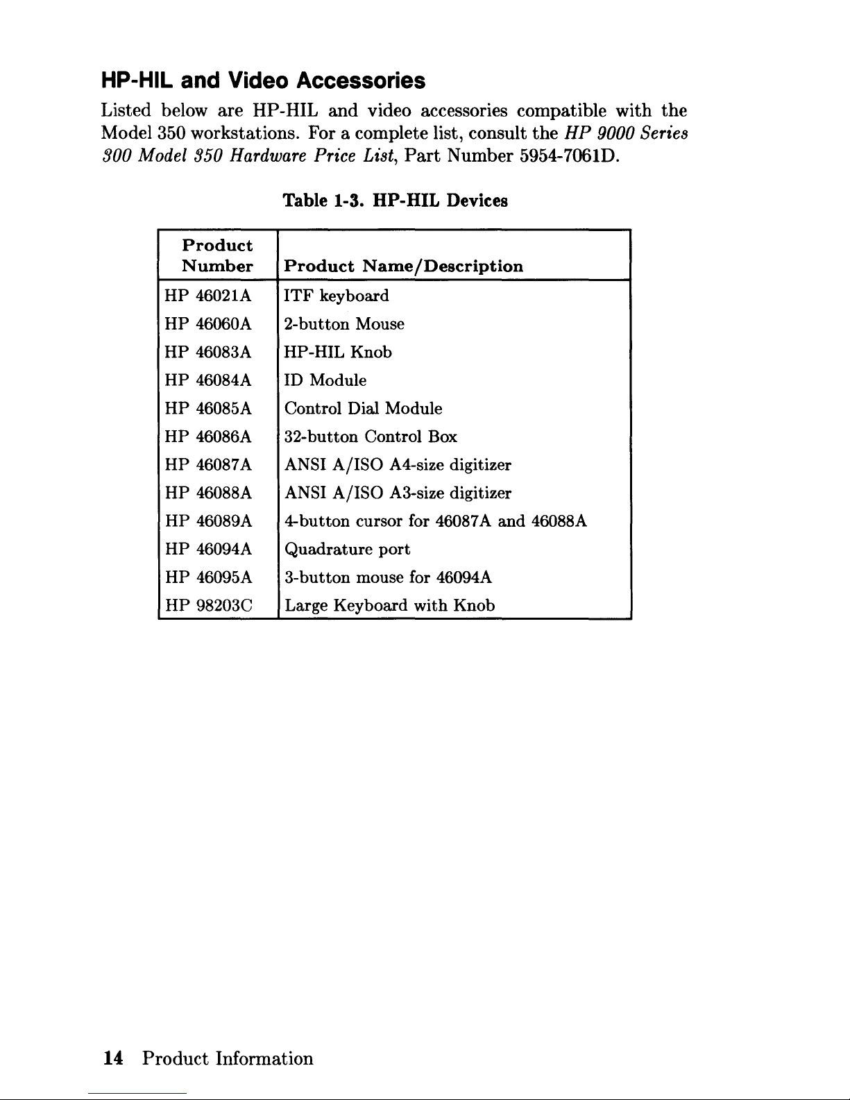
HP-HIL and Video Accessories
Listed below are HP-HIL
and
video accessories compatible with
the
Model 350 workstations. For a complete list, consult
the
HP
9000 Series
300 Model 350 Hardware Price List,
Part
Number 5954-7061D.
Table 1-3. HP-HIL Devices
Product
Number
Product
Name/Description
HP
46021A
ITF
keyboard
HP
46060A
2-button
Mouse
HP
46083A
HP-HIL
Knob
HP
46084A ID Module
HP
46085A Control Dial Module
HP
46086A
32-button
Control Box
HP
46087A ANSI
A/ISO
A4-size digitizer
HP
46088A
ANSI
A/ISO
A3-size digitizer
HP
46089A
4-button
cursor for 46087 A
and
46088A
HP
46094A
Quadrature
port
HP
46095A
3-button
mouse for 46094A
HP
98203C
Large
Keyboard
with
Knob
14
Product
Information
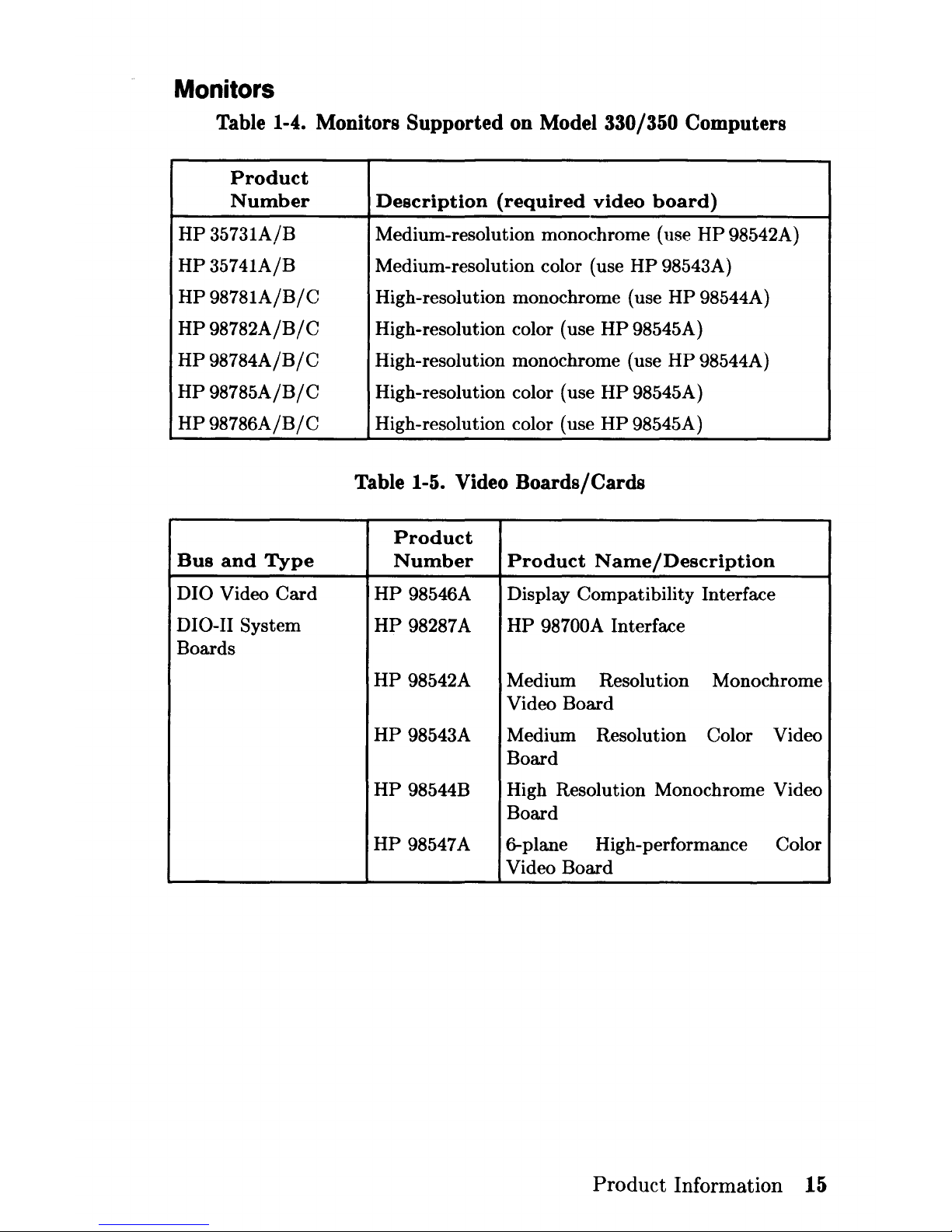
Monitors
Table 1-4. Monitors Supported on Model 330/350 Computers
Product
Number
Description
(required
video
board)
HP
35731A/B
Medium-resolution monochrome (use
HP
98542A)
HP
35741A/B
Medium-resolution color (use
HP
98543A)
HP
98781A/B/C
High-resolution monochrome (use
HP
98544A)
HP
98782A/B/C
High-resolution color (use
HP
98545A)
HP
98784A/B/C
High-resolution monochrome (use
HP
98544A)
HP
98785A/B/C
High-resolution color (use
HP
98545A)
HP
98786A/B/C
High-resolution color (use
HP
98545A)
Table 1-5. Video Boards/Cards
Product
Bus
and
Type
Number
Product
Name/Description
DIO Video
Card
HP
98546A Display Compatibility Interface
DIO-II System
HP
98287A
HP
98700A Interface
Boards
HP
98542A Medium Resolution Monochrome
Video Board
HP
98543A Medium Resolution Color Video
Board
HP
98544B High Resolution Monochrome Video
Board
HP
98547A
6-plane
High-performance Color
Video Board
Product
Information 15
 Loading...