

HP 9000 310, 9000 320, 98568A Service Information Manual
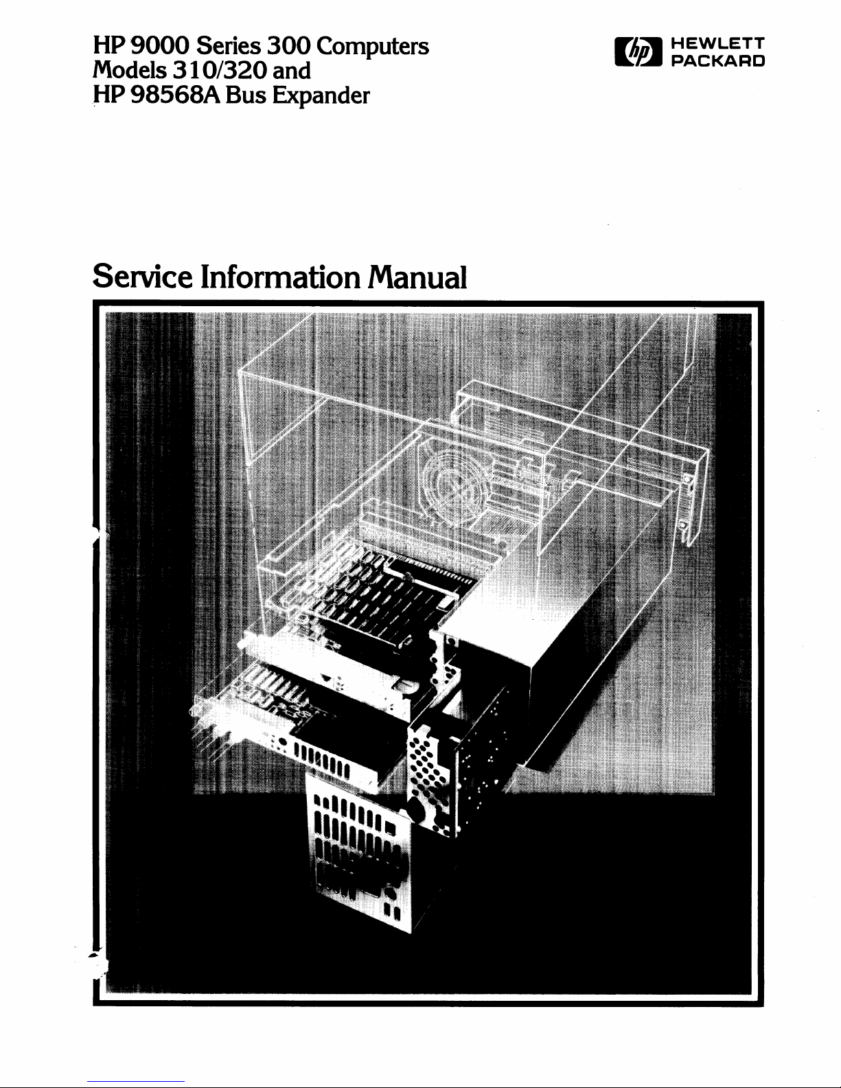
HP
9000
Series
300
Computers
Models
310/320
and
J-IP
98568A
Bus Expander
Service Information
Manual
FliDW
HEWLETT
~~
PACKARD

Service Information Manual
for
HP
9000
Series
300
Computers
Model
310/320
and
HP
98568A
Bus
Expander
Manual Reorder No. 98561-90030
© Copyright 1985, 1986 Hewlett-Packard Company
This document contains proprietary information which
is
protected
by
copyright.
All
rights
are
reserved.
No
part of this document may
be
photocopied, reproduced or translated to another language without the prior written consent of Hewlett-Packard Company. The information
contained
in
this document
is
subject to change without notice.
Restricted Rights Legend
Use,
duplication or disclosure
by
the Government
is
subject to restrictions
as
set forth
in
paragraph (b)(3)(8) of the Rights
in
Technical Data
and Software
clause
in
DAR
7-104.9(a).
Hewlett-Packard
Company
3404 East Harmony Road, Fort Collins, Colorado 80525
Printing History
New editions of this manual
will
incorporate
all
material updated since the previous edition. Update
packages may be issued between editions and contain replacement and additional pages
to
be merged
into the manual
by
the user. Each updated page
will
be indicated
by
a revision date
at
the bottom of
the page. A vertical bar
in
the margin indicates the changes on each page. Note that pages which are
rearranged due to changes on a previous page
are
not considered revised.
The
manual printing
date
and part number indicate its current edition.
The
printing
date
changes when
a new edition
is
printed. (Minor corrections and updates which
are
incorporated
at
reprint do not
cause the date
to
change.)
The
manual part number changes when extensive technical changes are
incorporated.
June
1985
... Edition 1
January
1986
... Edition 2
NOTICE
The information contained
in
this document
is
subject to change without notice.
HEWLETT-PACKARD
MAKES
NO
WARRANTY
OF
ANY KIND WITH REGARD TO THIS MANUAL, INCLUDING, BUT NOT
LIMITED TO,
THE IMPLIED WARRANTIES
OF
MERCHANTABILITY AND FITNESS
FOR
A PARTICULAR PURPOSE. Hewlett-
Packard shall not be liable for errors contained herein or direct, indirect, special, incidental or consequential damages
in
connection with the furnishing, performance, or use
of
this material.
WARRANTY
A copy of the specific warranty terms applicable to your Hewlett-Packard product and replacement parts
can
be
obtained from
your
local Sales and Service Office.
ii
Table
of
Contents
Chapter
1
Product
Information
Introduction.
. . . . . . . . . . . . . . . . . . . . . . . . . . . . . . . . . . . . . . . . . . . . . . . . . . . . . . . . . . . . . . .
..
1
Product
NUInbers
and
Terms.
. . . . . . . . . . . . . . . . . . . . . . . . . . . . . . . . . . . . . . . . . . . . . . . .
..
1
Product
Identification Terms . . . . . . . . . . . . . . . . . . . . . . . . . . . . . . . . . . . . . . . . . . . . .
..
1
Hardware
Terminology
....................................................
2
Software Terminology
.....................................................
3
Hardware
Documentation
Organization.
. . . . . . . . . . . . . . . . . . . . . . . . . . . . . . . . . . . . . . .
..
4
HP
Series 200/300
Cornputer
Test Tools
Manual.
. . . . . . . . . . . . . . . . . . . . . . . . . . .
..
4
HP
9000 Series 300 COInputer
/Bus
Expander
Service Information
Manual.
. . . . .
..
5
HP
9000 Series 300 COInputers Configuration Reference Manual
................
6
Series
300 Service Notes
...................................................
6
Series
300 Service
Handbook
...............................................
7
HP
9000 Series
200/300/500
Site
Preparation
Manual
.........................
8
Installation
Notes.
. . . . . . . . . . . . . . . . . . . . . . . . . . . . . . . . . . . . . . . . . . . . . . . . . . . . . .
..
9
Series
300 Installation Reference . . . . . . . . . . . . . . . . . . . . . . . . . . . . . . . . . . . . . . . . . .
..
9
Product
Number
Conventions
...............................................
"
10
Series 300
Computer
System Configurations
...............................
"
12
Determining
Computer
System Numbers
..................................
"
15
Determining Bundled System N unlbers
...................................
" 16
Specifications
..............................................................
"
17
Physical
................................................................
17
Power Line Voltage
and
Frequency
.......................................
"
17
Backplane Power Available
..............................................
"
17
Environmental
........................................................
'"
18
System Clock. . . . . . . . . . . . . . . . . . . . . . . . . . . . . . . . . . . . . . . . . . . . . . . . . . . . . . . . . .
..
18
Shipping Information
...................................................
"
18
Service
Support.
. . . . . . . . . . . . . . . . . . . . . . . . . . . . . . . . . . . . . . . . . . . . . . . . . . . . . . . . . . .
..
19
Repair Philosophy
.......................................................
19
Schematics
............................................................
" 19
Supported
Configurations
...............................................
"
19
Hewlett Packard
Support
.................................................
19
Chapter
2
Assembly Replacement
IntroductioIl
................................................................
"
21
Assembly Access Flow
Chart
............................................
"
21
Tools Required
........................................................
"
24
Safety
Precaution~
.....................................................
" 24
Electro-Static Discharge
Precautions
.......................................
25
Assembly Replacement
Procedures
...........................................
" 26
Overview
...............................................................
26
Fuse
..................................................................
" 27
HP-HIL
Devices.
. . . . . . . . . . . . . . . . . . . . . . . . . . . . . . . . . . . . . . . . . . . . . . . . . . . . . .
..
27
Processor
Board
.......................................................
" 27
Video Boards
..........................................................
"
28
I/O
Cards
..............................................................
28
Accessory
Cards
.......................................................
"
29
Table
of
Contents
iii
Power Supply
...........................................................
29
Top
Cover
..............................................................
30
Front Panel
.......
. . . . . . . . . . . . . . . . . . . . . . . . . . . . . . . . . . . . . . . . . . . . . . . . . . . .
..
31
Fans
...................................................................
33
Fan Housing. . . . . . . . . . . . . . . . . . . . . . . . . . . . . . . . . . . . . . . . . . . . . . . . . . . . . . . . . . .
..
34
Motherboard
. . . . . . . . . . . . . . . . . . . . . . . . . . . . . . . . . . . . . . . . . . . . . . . . . . . . . . . . . .
..
35
I/O
Card
Cage . . . . . . . . . . . . . . . . . . . . . . . . . . . . . . . . . . . . . . . . . . . . . . . . . . . . . . . .
..
35
Chapter 3
Functional Description
Power
Supply
...............................................................
37
General
Description.
. . . . . . . . . . . . . . . . . . . . . . . . . . . . . . . . . . . . . . . . . . . . . . . . . . .
..
37
Input
Section.
. . . . . . . . . . . . . . . . . . . . . . . . . . . . . . . . . . . . . . . . . . . . . . . . . . . . . . . . .
..
38
Rectification
and
Switching Control
Circuits.
. . . . . . . . . . . . . . . . . . . . . . . . . . . . . .
..
39
Power
Supply Regulators
.................................................
40
Protection
and
Reset Circuits
.............................................
41
Power
Distribution.
. . . . . . . . . . . . . . . . . . . . . . . . . . . . . . . . . . . . . . . . . . . . . . . . . . . .
..
41
98561-66511 Processor
Board
..................................................
43
General Description . . . . . . . . . . . . . . . . . . . . . . . . . . . . . . . . . . . . . . . . . . . . . . . . . . . .
..
43
System
Timer
. . . . . . . . . . . . . . . . . . . . . . . . . . . . . . . . . . . . . . . . . . . . . . . . . . . . . . . . .
..
45
Central
Processing Unit
..................................................
45
RAM
...................................................................
45
RS-232
.................................................................
46
HP
-IB Interface. . . . . . . . . . . . . . . . . . . . . . . . . . . . . . . . . . . . . . . . . . . . . . . . . . . . . . . .
..
46
Video Circuits . . . . . . . . . . . . . . . . . . . . . . . . . . . . . . . . . . . . . . . . . . . . . . . . . . . . . . . . .
..
47
Key
board
Electronics. . . . . . . . . . . . . . . . . . . . . . . . . . . . . . . . . . . . . . . . . . . . . . . . . . .
..
47
Boot
ROMs
and
Self-Test LEDs
...........................................
47
Other
Circuits.
. . . . . . . . . . . . . . . . . . . . . . . . . . . . . . . . . . . . . . . . . . . . . . . . . . . . . . . .
..
47
HP-HIL
....................................................................
48
General Description . . . . . . . . . . . . . . . . . . . . . . . . . . . . . . . . . . . . . . . . . . . . . . . . . . . .
..
48
Link Controller . . . . . . . . . . . . . . . . . . . . . . . . . . . . . . . . . . . . . . . . . . . . . . . . . . . . . . . .
..
48
Interface Cables
.........................................................
50
Device Controller . . . . . . . . . . . . . . . . . . . . . . . . . . . . . . . . . . . . . . . . . . . . . . . . . . . . . .
..
51
98561-66512 Processor
Board
. . . . . . . . . . . . . . . . . . . . . . . . . . . . . . . . . . . . . . . . . . . . . . . .
..
53
General Description . . . . . . . . . . . . . . . . . . . . . . . . . . . . . . . . . . . . . . . . . . . . . . . . . . . .
..
53
RAM
...................................................................
53
98561-6651:3 Processor
Board.
. . . . . . . . . . . . . . . . . . . . . . . . . . . . . . . . . . . . . . . . . . . . . . .
..
55
General Description . . . . . . . . . . . . . . . . . . . . . . . . . . . . . . . . . . . . . . . . . . . . . . . . . . . .
..
55
RAM
...................................................................
56
98561-66519
Processor
Board.
. . . . . . . . . . . . . . . . . . . . . . . . . . . . . . . . . . . . . . . . . . . . . . .
..
57
General Description
.........................................
'.
. . . . . . . . . .
..
57
Central
Processing Unit
...................................................
58
Coprocessor . . . . . . . . . . . . . . . . . . . . . . . . . . . . . . . . . . . . . . . . . . . .
..
. . . . . . . . . . . . . .
..
58
Menlory Management
Unit.
. . . . . . . . . . . . . . . . . . . . . . . . . . . . . .
..
. . . . . . . . . . . . . .
..
58
Cache Memory Sub-System
................................................
58
Boot
RO Ms
and
Self-Test LEDs
.........................
. . . . . . . . . . . . . . . .
..
58
Motherboard
...............................................
, . . . . . . . . . . . . . .
..
59
General Description
.....................................
, . . . . . . . . . . . . . .
..
59
Backplane
Board
.......
, . . . . . . . . . . . . . . . . . . . . . . . . . . . . . . . . . . . . . . . . . . . . . . . . . . .
..
59
General Description
.....................................
, . . . . . . . . . . . . . .
..
59
iv
Table of
Contents

Video
Boards.
. . . . . . . . . . . . . . . . . . . . . . . . . . . . . . . . . . . . . . . . . . . . . . . . . . . . . . . . . . . . .
..
60
General
Description.
. . . . . . . . . . . . . . . . . . . . . . . . . . . . . . . . . . . . . . . . . . . . . . . . . . .
..
60
Video
RAM
. . . . . . . . . . . . . . . . . . . . . . . . . . . . . . . . . . . . . . . . . . . . . . . . . . . . . . . . . . .
..
62
Color Mapping
..........................................................
62
Display Controller
.......................................................
62
Frame
Buffer Controller
..................................................
63
Video
OutI)ut
...........................................................
63
Display
RA11 Control
..................
. . . . . . . . . . . . . . . . . . . . . . . . . . . . . . . .
..
63
Interrupt
Structure.
. . . . . . . . . . . . . . . . . . . . . . . . . . . . . . . . . . . . . . . . . . . . . . . . . . . .
..
63
ID/FONT
ROM
.........................................................
64
Clocks
and
Timing
. . . . . . . . . . . . . . . . . . . . . . . . . . . . . . . . . . . . . . . . . . . . . . . . . . . . .
..
64
Human
Interface
Card.
. . . . . . . . . . . . . . . . . . . . . . . . . . . . . . . . . . . . . . . . . . . . . . . . . . . . .
..
65
General Description . . . . . . . . . . . . . . . . . . . . . . . . . . . . . . . . . . . . . . . . . . . . . . . . . . . .
..
65
Functional Description. . . . . . . . . . . . . . . . . . . . . . . . . . . . . . . . . . . . . . . . . . . . . . . . . .
..
65
HP
98546 Display Compatibility
Interface.
. . . . . . . . . . . . . . . . . . . . . . . . . . . . . . . . . . . .
..
66
General Description . . . . . . . . . . . . . . . . . . . . . . . . . . . . . . . . . . . . . . . . . . . . . . . . . . . .
..
66
Video
Card
.............................................................
67
Graphics
Card.
. . . . . . . . . . . . . . . . . . . . . . . . . . . . . . . . . . . . . . . . . . . . . . . . . . . . . . . .
..
68
Chapter 4
Boot
ROM Functions
Introduction.
. . . . . . . . . . . . . . . . . . . . . . . . . . . . . . . . . . . . . . . . . . . . . . . . . . . . . . . . . . . . . .
..
69
Power-Up Sequence
..........................................................
69
Power-up
Algorithm.
. . . . . . . . . . . . . . . . . . . . . . . . . . . . . . . . . . . . . . . . . . . . . . . . . . .
..
69
Configure Mode Software Override . . . . . . . . . . . . . . . . . . . . . . . . . . . . . . . . . . . . . . .
..
74
Force Long Memory Test
.................................................
75
Continuous Self-Test
.....................................................
75
50 or 60 Hz
CRT
........................................................
76
The
Human
Interface.
. . . . . . . . . . . . . . . . . . . . . . . . . . . . . . . . . . . . . . . . . . . . . . . . . . . . . .
..
77
Output
Devices. . . . . . . . . . . . . . . . . . . . . . . . . . . . . . . . . . . . . . . . . . . . . . . . . . . . . . . .
..
77
Input
Devices
...........................................................
77
Remote
Human
Interface
.....................................................
81
Self-Test . . . . . . . . . . . . . . . . . . . . . . . . . . . . . . . . . . . . . . . . . . . . . . . . . . . . . . . . . . . . . . . . . .
..
83
Hardware
Initialization
Support.
. . . . . . . . . . . . . . . . . . . . . . . . . . . . . . . . . . . . . . . . .
..
83
Assembly Self-Test
Support.
. . . . . . . . . . . . . . . . . . . . . . . . . . . . . . . . . . . . . . . . . . . . .
..
83
Tests
Perforrned by
the
Boot
RO
~1
. . . . . . . . . . . . . . . . . . . . . . . . . . . . . . . . . . . . . . .
..
84
Memory Tests . . . . . . . . . . . . . . . . . . . . . . . . . . . . . . . . . . . . . . . . . . . . . . . . . . . . . . . . .
..
91
Booting
Operating
Systems
...................................................
93
Boot
System
Selection.
. . . . . . . . . . . . . . . . . . . . . . . . . . . . . . . . . . . . . . . . . . . . . . . . .
..
93
Unattended
Operation.
. . . . . . . . . . . . . . . . . . . . . . . . . . . . . . . . . . . . . . . . . . . . . . . . .
..
93
Attended
Operation.
. . . . . . . . . . . . . . . . . . . . . . . . . . . . . . . . . . . . . . . . . . . . . . . . . . .
..
93
Boot System
Priority
Control.
. . . . . . . . . . . . . . . . . . . . . . . . . . . . . . . . . . . . . . . . . . .
..
97
Default Mass Storage
Variable.
. . . . . . . . . . . . . . . . . . . . . . . . . . . . . . . . . . . . . . . . . .
..
98
Supported
Boot
Configurations.
. . . . . . . . . . . . . . . . . . . . . . . . . . . . . . . . . . . . . . . . .
..
99
Booting From
The
SRM . . . . . . . . . . . . . . . . . . . . . . . . . . . . . . . . . . . . . . . . . . . . . . .
..
101
Chapter 5
Troubleshooting
Introduction.
. . . . . . . . . . . . . . . . . . . . . . . . . . . . . . . . . . . . . . . . . . . . . . . . . . . . . . . . . . . . .
..
103
The
Troubleshooting
Process.
. . . . . . . . . . . . . . . . . . . . . . . . . . . . . . . . . . . . . . . . . .
..
103
Table of
Contents
v
Materials
Required.
. . . . . . . . . . . . . . . . . . . . . . . . . . . . . . . . . . . . . . . . . . . . . . . . . . .
..
103
Test
LED
Displays.
. . . . . . . . . . . . . . . . . . . . . . . . . . . . . . . . . . . . . . . . . . . . . . . . . . .
..
103
Troubleshooting
Procedures.
. . . . . . . . . . . . . . . . . . . . . . . . . . . . . . . . . . . . . . . . . . . . . . .
..
104
System
Level.
. . . . . . . . . . . . . . . . . . . . . . . . . . . . . . . . . . . . . . . . . . . . . . . . . . . . . . . .
..
104
COlnputer
/Bus
Expander
Troubleshooting
.................................
104
Inoperative Unit
Procedure
..................................................
106
Live Unit
Procedure.
. . . . . . . . . . . . . . . . . . . . . . . . . . . . . . . . . . . . . . . . . . . . . . . . . . . . . .
..
107
Minimum Configuration
.................................................
107
Functional Unit
Troubleshooting.
. . . . . . . . . . . . . . . . . . . . . . . . . . . . . . . . . . . . . . . . . . .
..
109
Intermediate
Configuration.
. . . . . . . . . . . . . . . . . . . . . . . . . . . . . . . . . . . . . . . . . . . .
..
109
Test Tools
.................................................................
111
Overview
..............................................................
111
Computer
Tests.
. . . . . . . . . . . . . . . . . . . . . . . . . . . . . . . . . . . . . . . . . . . . . . . . . . . . . .
..
111
System Functional Tests . . . . . . . . . . . . . . . . . . . . . . . . . . . . . . . . . . . . . . . . . . . . . . .
..
111
CS / 80 Exercisers
.......................................................
111
Package
Contents.
. . . . . . . . . . . . . . . . . . . . . . . . . . . . . . . . . . . . . . . . . . . . . . . . . . . .
..
112
Turn-on Self Test
......
. . . . . . . . . . . . . . . . . . . . . . . . . . . . . . . . . . . . . . . . . . . . . . . . . . .
..
112
Self-Test
Error
Displays. . . . . . . . . . . . . . . . . . . . . . . . . . . . . . . . . . . . . . . . . . . . . . . .
..
112
Failure Indications . . . . . . . . . . . . . . . . . . . . . . . . . . . . . . . . . . . . . . . . . . . . . . . . . . . .
..
115
Chapter
6
References
How
to
Use
This
Chapter.
. . . . . . . . . . . . . . . . . . . . . . . . . . . . . . . . . . . . . . . . . . . . . . . . .
..
121
Service Information
Locator.
. . . . . . . . . . . . . . . . . . . . . . . . . . . . . . . . . . . . . . . . . . . . . . .
..
121
Localized System Identification . . . . . . . . . . . . . . . . . . . . . . . . . . . . . . . . . . . . . . . . . . . . .
..
123
Related
Documentation.
. . . . . . . . . . . . . . . . . . . . . . . . . . . . . . . . . . . . . . . . . . . . . . . . . . .
..
124
BASIC
Operating
System.
. . . . . . . . . . . . . . . . . . . . . . . . . . . . . . . . . . . . . . . . . . . . .
..
124
Pascal
Operating
Systems.
. . . . . . . . . . . . . . . . . . . . . . . . . . . . . . . . . . . . . . . . . . . . .
..
126
HP-UX
................................................................
127
Installation
Manuals/Notes.
. . . . . . . . . . . . . . . . . . . . . . . . . . . . . . . . . . . . . . . . . . . .
..
130
vi
Table of
Contents
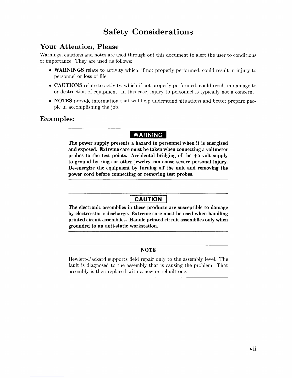
Safety
Considerations
Your
Attention,
Please
Warnings, cautions
and
notes are used
through
out
this
document
to
alert
the
user
to
conditions
of inlportance.
They
are used as follows:
• WARNINGS relate
to
activity which, if
not
properly performed, could result in injury
to
personnel
or
loss
of
life.
• CAUTIONS relate
to
activity, which if
not
properly performed, could result in
damage
to
or
destruction
of
equipment.
In
this
case, injury
to
personnel
is
typically
not
a concern.
• NOTES provide information
that
will help
understand
situations
and
better
prepare
peo-
ple in accomplishing
the
job.
Examples:
WARNING
The power supply presents a hazard to personnel when it is energized
and exposed. Extreme care must be taken when connecting a voltmeter
probes to the test points. Accidental bridging
of
the
+5
volt supply
to ground
by
rings or other jewelry can cause severe personal injury.
De-energize the equipment
by
turning off the unit and removing the
power cord before connecting or removing test probes.
CAUTION
The electronic assemblies in these products are susceptible to damage
by
electro-static discharge. Extreme care must be used when handling
printed circuit assemblies. Handle printed circuit assemblies only when
grounded to an anti-static workstation.
NOTE
Hewlett-Packard
supports
field repair only
to
the
assembly level.
The
fault
is
diagnosed
to
the
assembly
that
is
causing
the
problem.
That
assembly
is
then
replaced with a new
or
rebuilt one.
vii

viii
Chapter
1
Product
Information
Introduction
Series 300 Computers are modular cOInputers.
The
HP
98568A Bus Expander permits
an
additional eight accessory slots
to
be used in
the
system.
With a low
entry cost
and
a wide
range of accessories
and
interfaces 1 these computers provide technical-professional workstations
that
maximize productivity. Processing
is
accomplished by
the
MC68010 or MC68020 CPUs
enabling high-speed
data
access
and
manipulation.
Available operating systems for these computers include
BASIC, Pascal,
and
HP-UX. Several
application programs are also available
that
run
on any of these operating systems or on a subset
of one of them.
Product
Numbers
and
Terms
Several terms in this nlanual are used
to
describe
and
identify
the
various
parts
of
the
computer
and
bus expander. This section explains
the
terms used
to
improve your understanding of service
information.
Product
Identification
Terms
Product
Number
HP
9000 Series 300 Computer Systems are offered in two models. Model Numbers identifying
these computer systenls are:
• Model 310
•
Model 320.
A complete explanation of these names
and
numbers
is
shown
later
in this chapter. Configuration
and
other product information
is
also covered.
Product
Information 1
Serial
Numbers
Serial
numbers
are affixed
to
each
computer
and
bus
expander
for identification purposes. A
decal on each
product
has
the
serial nunlber. An example serial
number
is
explained below:
Serial No. 2322A01234
Location: Behind
the
power supply access cover on
the
bottom
of
the
chassis for
computer
and
bus expander.
Description:
5-digit unique identifying number.
Country
of Origin Code.
Product
Code, decoded as:
First
2 digits + 60 = Last 2 digits
of
year
product
was introduced
or
significantly changed.
Last 2 digits
=
number
of week in year
product
was introduced
or
significantly changed.
Hardware
Terminology
Hardware
is
used
to
define physical elements of these products. Different
parts
and
locations of
hardware items are explained below.
Products
Types
and
Parts
The
following
terms
are used
to
describe
products
and
their
main
parts
and
areas:
•
Computer
- A
product
containing
the
central processing
unit
(CPU)
and
other
assemblies
such as
RAM
cards, interface cards,
and
other
accessories. Sometimes
the
computer
is
referred
to
as
the
mainframe.
•
I/O
Card
cage -
The
narrow slots for accessories in
the
back
of
the
computer
and
bus
expander. Four slots are available in
the
computer, in
the
bus
expander
there
are eight
of
these slots. Distinction between these slots are:
•
Counting
from
the
top, every
odd
slot
is
an
accessory
card
slot .
• Counting from
the
top, every even slot
is
an
I/O
card
slot.
•
System
Slots - Two wider slots below
the
computer's
accessory slots for
the
processor
and
HP
9854X Video Boards.
•
Internal
(circuit) - A circuit, such as
an
RS-232 interface,
that
is
part
of
the
processor
board.
Internal
does
not
mean
'inside
the
computer's
case
parts'.
•
External
(circuit) - A circuit, such as
an
accessory
RAM
card,
that
is located on
an
assembly
other
than
the
processor board.
External
does
not
mean
'outside
the
computer's
case
parts'.
•
Peripheral
- A device
external
to
the
computer, such as a keyboard, monitor, disc drive,
plotter,
printer, bus expander, etc.
•
Bus
Expander
- A device
external
to
the
computer
that
connects
to
the
computer's
I/O
bus.
This
device provides power
to
its installed accessory
cards
and
permits
more
of
these
cards
to
be
used in
the
computer
system. Sometimes
they
are called bus extenders.
•
System -One
or
more
computers
with
one
or
more peripherals connected
together
to
run
an
application for a desired
end
result.
2
Product
Information
Assemblies
Assemblies in
tenns
used in
the
computer
this
rnanual are:
and
bus
expander
are
made
of
several
component
parts.
Identifying
• Cards - Assemblies installed in
•
I/O
Card - A
installed in
• Accessory Card - A
a peripheral device.
• Boards - Assenlblies installed in
Boards are
• Backplane -
computer,
Software
As used in
information can
Types
• Firmware -
• Operating Systems -
• Application Program - A series
this
of software are:
have various commands,
particular
cause specific actions, such as accounting, electro-mechanical design,
output,
is
stored
not
The
there's
Terminology
manual, software refers
be
changed
The
sequence, cause
etc.
This
in
or
card
I/O
slots. For example,
usually removed
board
data
information
on a medium
in
four connectors; in
and
or
instructions in Read-Only-Memory (ROM) chips.
Computer
statements,
the
I/O
that
outputs
card
that
only
They
are installed in
the
or
installed by users.
the
card
cage with connectors for
to
information
can
be
transferred
languages, such as BASIC, Pascal,
computer
is
and
to
of
operating
sometimes referred
can
be
card
cage slots .
to
and
an
RS-232
operates
two
computer
the
bus expander,
to
and
keywords
manipulate
system
transferred.
inputs
on
either
stored
another
that
data
program
to
from a peripheral device.
I/O
the
I/O
system slots,
as software as
card.
I/O
bus
and
does
or
accessory
cards
there
are
in,
or
on a device. Typically,
location in
when executed by
to
some desired
lines in a specific sequence
card
or
inside
to
plug into. In
eight.
the
computer
and
end
data
it
is information
HP-UX.
the
sampling
They
not
slots.
the
CPU
result.
are
talk.
to
product.
the
this
system.
They
in a
to
and
that
Prod
uct
Information 3
Hardware
Documentation
Organization
The
purpose
of
the
HP
Series 300
Computer
and
HP
98568A Bus
Expander
Hardware Docu-
mentation
is
to
support
the
installation
and
maintenance of these products. Hardware Docu-
mentation
consists of six types of manuals:
•
HP
Series 200/300
Computer
Test Tools Manual
•
HP
Series 300
Computer
and
HP
98568A Bus
Expander
Service Information Manual
•
HP
Series 300 Service Handbook
•
HP
Series 300 Service Notes
•
HP
9000 Series 200/500 Site
Preparation
Manual
• Various Installation Notes
•
HP
Series 300 Installation Reference
•
HP
Series 300
Computer
System Configuration Reference
A complete listing of titles
and
part
numbers is in
Chapter
6 of this manual
and
the
HP
Series
300 Service
Handbook,
Chapter
10.
HP
Series
200/300
Computer
Test
Tools
Manual
Series 200/300 Test Tools Manual
supports
a software package for verifying
the
integrity of
Series 300
computer
system installations.
The
Test Tools manual
and
its associated discs
permit
troubleshooting
computer
systems in failure analysis.
Part
numbers for
the
complete Test Tools
packages are:
• 09800-12300 for 3.5-inch disk drives.
• 09800-12500 for 5.25-inch disk drives.
Contents
of
the
four
parts
of
the
Test Tools Manual are
Part No. and Title
Contents
Part
I,
Introduction
and
Built-In Tests Introduces
the
Test Tools package
and
overviews
the
computer
self-tests
and
explains
what
the
different
tests
do.
Part
II,
Conlputer
Tests
Part
III, System Functional Tests
Part
IV,
CS/80
Exercisers
4
Product
Information
Covers loading
and
running of Series 200
and
300 Com-
puter
Tests. Each
test
is explained as
to
what
it
does.
Error
messages
are
listed
and
explained.
Tells how various computer-peripheral
tests
are
loaded
and
run. Tests are explained, error messages shown
and
defined. Examples of some
tests
are
given. Includes
tests
.for HP-HIL devices.
Explains how
tests
for
CS/80
disc drives are loaded, ran,
and
results are interpreted.
Error
messages are shown
as well as several examples of running
the
tests.
HP
Series
300
Computer
and
HP
98568A
Bus
Expander
Service
Information
Manual
This
manual
(the
one you're reading now) contains
tutorial
information on
the
computer's
and
bus
expander's
main features, functional descriptions
of
each assembly,
and
how
to
replace these
assemblies.
Its
purpose
is
to
serve as a learning tool in
training
environments wherein
the
service person
learns how
the
conlputer
and
bus
expander
works
and
its
parts
are replaced. Most of
the
information in
the
Service Information Manual is
not
found in
the
Service Handbook.
Organization
of
the
Service Information Manual
is
as follows:
Chapter No. and Title
Front
Matter
Chapter
1:
Product
Information
Chapter
2:
Assembly Replacement
Chapter
3:
Functional Description
Chapter
4:
Boot
RO~1
Functions
Chapter
5:
Troubleshooting
Chapter
6:
Reference
Contents
Has warranty, printing history, Table of Contents,
and
Safety Situations explained.
Introduces
the
computer/bus
expander, covers features,
specifications, options, accessories,
operating
systems,
repair philosophy,
and
a general description
of
the
Se-
ries 300
Computers
and
HP
98568 Bus Expanders. Has
an
overview of how
the
Hardware
Documentation
is or-
ganized.
In
this
chapter, disassembly
and
reassembly of all field
replaceable
parts
for
the
computer
and
bus
expander
are
covered. Reference
to
the
Service
Handbook
is
made
for
part
number
information.
Each assemblies functional description
is
covered
to
block diagram level.
The
sequence
of
events for power-up, self-tests,
and
booting
an
operating
system are explained.
This
chapter
contains
tutorial
infonnation
for
trou-
bleshooting
the
computer
and
bus expander.
It
has
self-test errors as provided for
the
computer
and
bus
expander
explained.
Has a Service Information Locator,
documentation
ref-
erences,
and
other
helpful information.
Product
Information 5
HP
9000
Series
300
Computers
Configuration
Reference
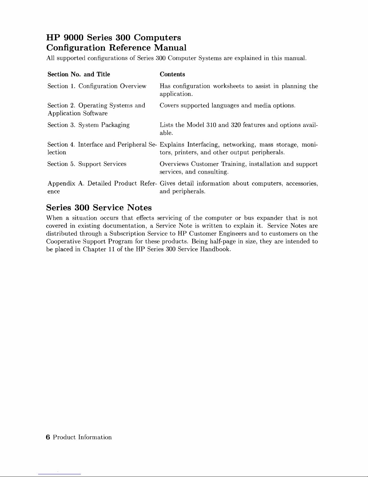
Manual
All
supported
configurations
of
Series 300
Computer
Systems are explained in
this
manual.
Section No. and Title
Section
1.
Configuration Overview
Section
2.
Operating
Systems
and
Application Software
Section
3.
System Packaging
Contents
Has configuration worksheets
to
assist in planning
the
application.
Covers
supported
languages
and
media options.
Lists
the
Model 310
and
320 features
and
options avail-
able.
Section
4.
Interface
and
Peripheral Se- Explains Interfacing, networking, mass storage, moni-
lection tors, printers,
and
other
output
peripherals.
Section
5.
Support
Services Overviews
Customer
Training, installation
and
support
services,
and
consulting.
Appendix
A.
Detailed
Product
Refer- Gives detail information
about
computers, accessories,
ence
and
peripherals.
Series
300
Service
Notes
When a
situation
occurs
that
effects servicing of
the
computer
or
bus
expander
that
is
not
covered in existing
documentation,
a Service Note is
written
to
explain it. Service Notes are
distributed
through
a Subscription Service
to
HP
Customer
Engineers
and
to
customers on
the
Cooperative
Support
Program
for these products. Being half-page in size,
they
are intended
to
be
placed in
Chapter
11
of
the
HP
Series 300 Service Handbook.
6
Product
Information
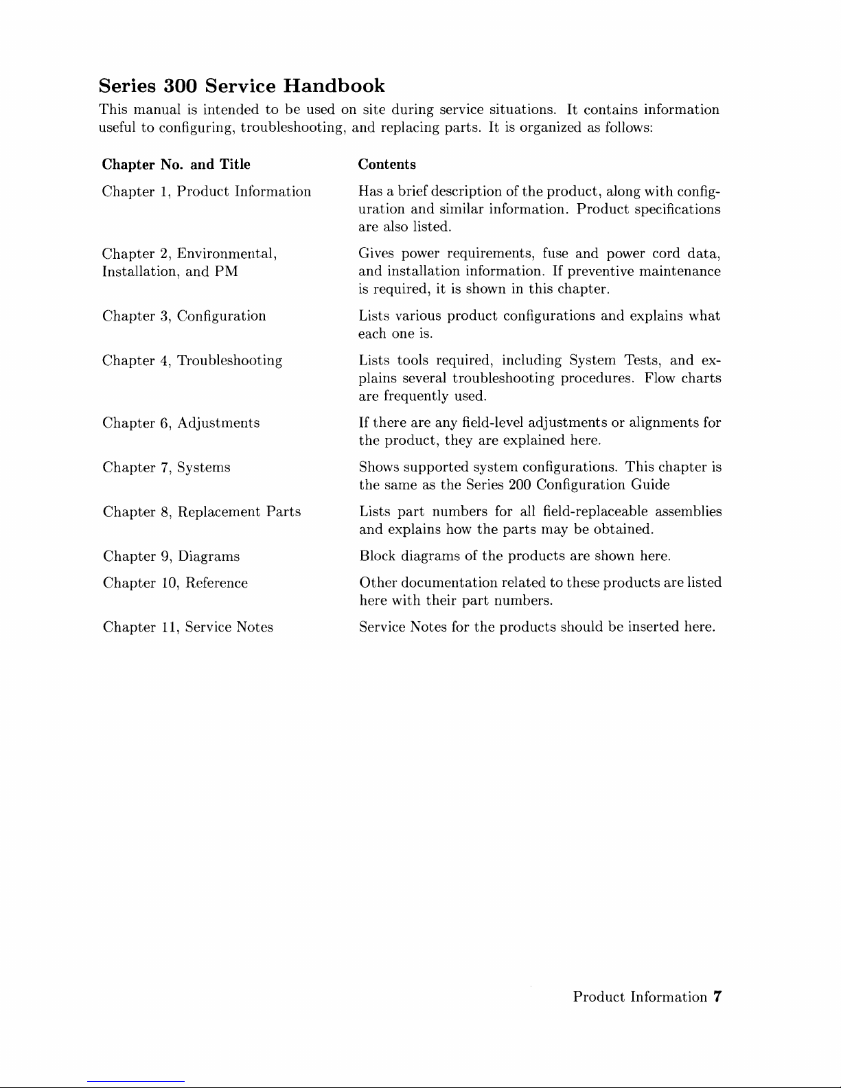
Series
This
manual
useful
to
300
Service
is
intended
configuring, troubleshooting,
Handbook
to
be
used on site
and
during
replacing
service situations.
parts.
It
is
organized as follows:
It
contains information
Chapter No. and Title
Chapter
Chapter
Installation,
Chapter
Chapter
Chapter
Chapter
Chapter
Chapter
1,
Product
2, Environmental,
and
3, Configuration
4,
Troubleshooting
6,
Adjustments
7,
Systems
8,
Replacement
9, Diagrams
Information
PM
Parts
Contents
Has a brief description of
uration
are also listed.
Gives power requirements, fuse
and
is
Lists various
each one is.
Lists tools required, including System Tests,
plains several troubleshooting procedures. Flow
are frequently used.
If
the
Shows
the
Lists
and
Block diagrams of
and
similar information.
installation information.
required, it is shown in
product
there
are any field-level
product,
same as
part
explains how
they
are explained here.
supported
numbers for all field-replaceable assemblies
system configurations.
the
Series 200 Configuration Guide
the
the
this
configurations
adjustments
parts
may
the
products
product,
If
chapter.
along
with
Product
and
preventive maintenance
be
obtained.
are shown here.
specifications
power cord
and
explains
or
alignments for
This
chapter
config-
data,
what
and
charts
ex-
is
Chapter
Chapter
10, Reference
11, Service Notes
Other
here
Service Notes for
documentation
with
their
part
the
related
numbers.
products
to
these
should
products
be
inserted here.
are
listed
Product
Information 7

HP
9000
Series
200/300/500
Site
Explains site
physical, environmental
Preparation
preparation
Chapter No. and Title
Chapter
Chapter
Chapter
Environment
Chapter
Environment
Chapter
Necessities
1,
Introduction
2,
Responsibilities
3,
Preparing
4,
Preparing
5, Providing
Manual
and
and
the
Electrical
the
Physical
Other
how
to
prepare
electrical requirements.
the
computer
Contents
Explains
tion Manual.
Identifies
the
frame for
people who
Includes power specifications, dealing
terference, connecting cables,
configurations.
Explains
contaminants,
movement
Covers media storage,
computer
which are
the
the
customer
Series 9000
setting
heat
and
supplies,
an
operation
site for
Its
organization
purpose
can
and
and
storage.
integral
of a
and
and
HP
Computer
up
the
computer
provide assistance.
humidity considerations,
shipping weights
equipment
and
nearby telephones for assistance
part
computer
hardware
contents
responsibilities for preparing
System site. Includes a time-
of
preparing
system.
installation. Covers
is
shown below.
of
the
Site
system,
with
and
data
communication
and
dimensions for
and
record protection,
for
and
Prepara-
and
identifies
electrical in-
airborne
sustaining
Chapter
and
Space
Chapter
Arrives
Appendix
Appendix
6,
Equipment
Planning
7,
When
A
B
Arrangement
Your
Computer
and
Provides information
the
cation of
Discusses
dinated
age in shipment, unpacking
the
installation of
product
Lists
heat
generation,
ments,
Contains forms
Installation Worksheet,
a Site Completion Checklist.
and
computer
the
final
preparation
deliveries, arrival dates, how
HP
specifications for electrical requirements,
temperature
shipping dimensions.
to
use for
guidelines for planning
system equipment
9000
preparing
Shipment
at
your site.
for system arrival, coor-
to
check for dam-
the
cartons,
Computer
and
Scheduling Form,
and
Systenls.
humidity
the
site, such as
scheduling
the
lo-
require-
Pre-
and
8
Product
Information
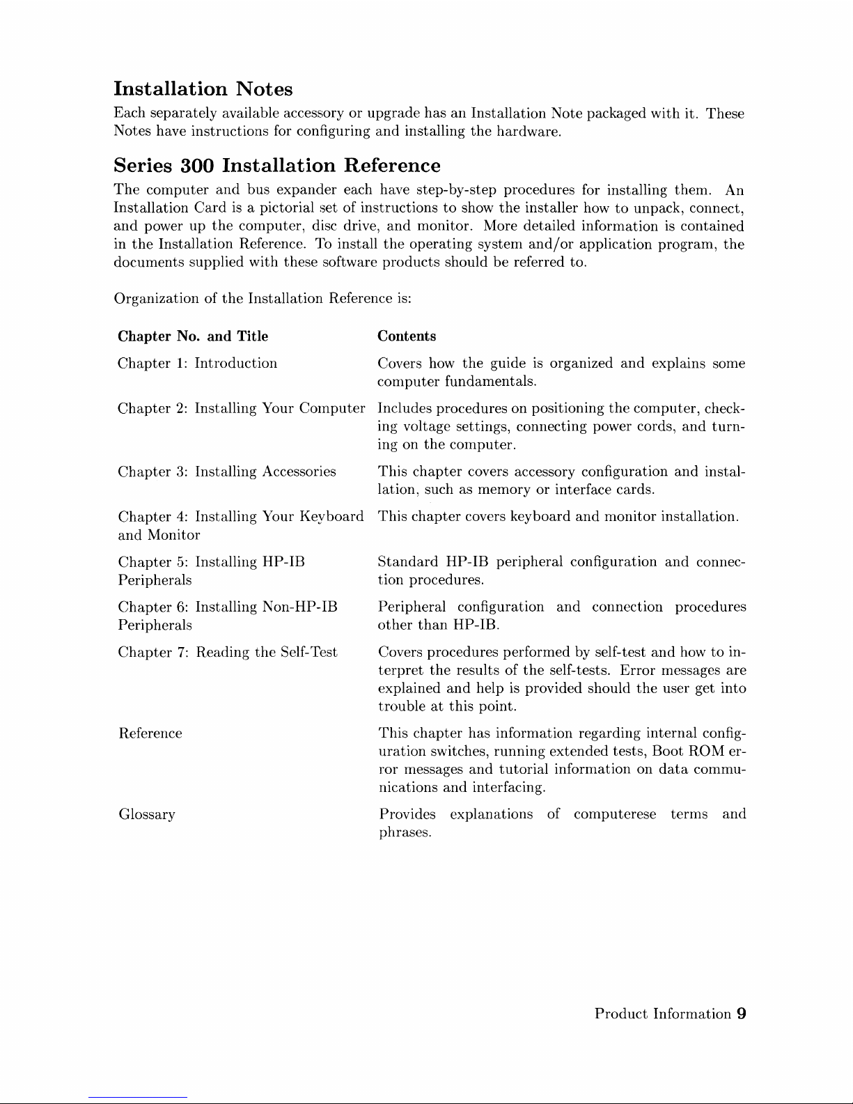
Installation
Notes
Each separately available accessory
or
upgrade has
an
Installation
Note packaged
with
it. These
Notes have instructions for configuring
and
installing
the
hardware.
Series
300
Installation
Reference
The
computer
and
bus
expander
each have step-by-step procedures for installing
them.
An
Installation
Card
is
a pictorial set of instructions
to
show
the
installer how
to
unpack, connect,
and
power up
the
computer,
disc drive,
and
monitor. More detailed information
is
contained
in
the
Installation Reference. To install
the
operating
system
and/or
application program,
the
documents supplied
with
these software
products
should
be
referred to.
Organization of
the
Installation Reference
is:
Chapter No. and Title
Chapter
1:
Introduction
Contents
Covers how
the
guide
is
organized
and
explains some
computer
fundamentals.
Chapter
2:
Installing Your COlnputer Includes procedures on positioning
the
computer,
check-
ing voltage settings, connecting power cords,
and
turn-
ing on
the
computer.
Chapter
3:
Installing Accessories
This
chapter
covers accessory configuration
and
instal-
lation, such as memory
or
interface cards.
Chapter
4:
Installing Your
Keyboard
This
chapter
covers keyboard
and
monitor
installation.
and
Monitor
Chapter
5:
Installing
HP
-IB
Peri pherals
Chapter
6:
Installing Non-HP-IB
Peri
pherals
Chapter
7:
Reading
the
Self-Test
Reference
Glossary
Standard
HP-IB peripheral configuration
and
connec-
tion procedures.
Peripheral configuration
and
connection procedures
other
than
HP-IB.
Covers procedures performed by self-test
and
how
to
in-
terpret
the
results
of
the
self-tests.
Error
messages
are
explained
and
help is provided should
the
user get into
trouble
at
this
point.
This
chapter
has information regarding internal config-
uration
switches,
running
extended
tests,
Boot
ROM
er-
ror messages
and
tutorial
information on
data
commu-
nications
and
interfacing.
Provides explanations of computerese
terms
and
phrases.
Product
Information 9
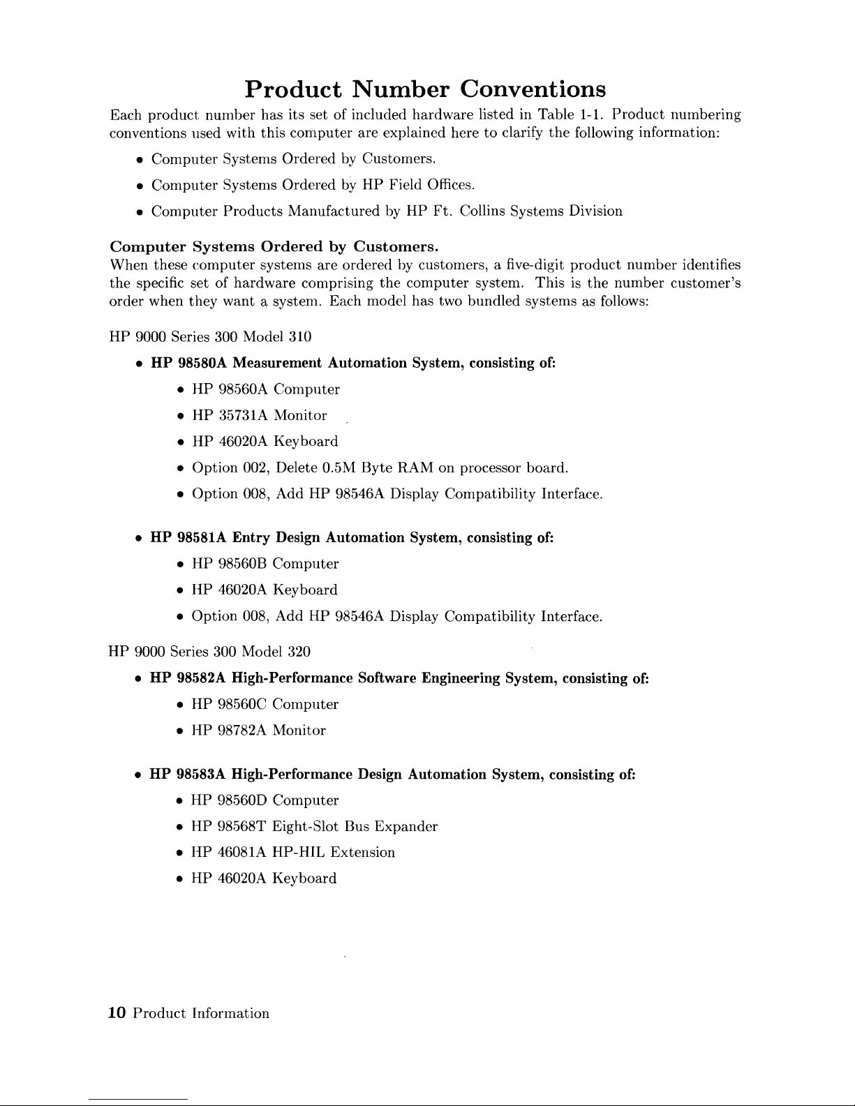
Product
Number
Conventions
Each
product
number
has its set of included
hardware
listed in Table 1-1.
Product
numbering
conventions used with
this
computer
are explained here
to
clarify
the
following information:
•
Computer
Systems
Ordered
by Customers.
•
Computer
Systems
Ordered
by
HP
Field Offices.
•
Computer
Products
Manufactured
by
HP
Ft.
Collins Systems Division
Computer
Systems
Ordered
by
Customers.
When
these
computer
systems are ordered by customers, a five-digit
product
number
identifies
the
specific
set
of
hardware
comprising
the
computer
system.
This
is
the
number
customer's
order
when
they
want
a system. Each model has two bundled systems as follows:
HP
9000 Series 300 Model 310
• HP 98580A
Measurement
Automation
System, consisting
of:
•
HP
98560A
Computer
•
HP
35731A Monitor
•
HP
46020A Key
board
•
Option
002, Delete 0.5M
Byte
RAM on processor board.
•
Option
008,
Add
HP
98546A Display Compatibility Interface.
• HP 98581A
Entry
Design
Automation
System, consisting of:
•
HP
98560B
Computer
•
HP
46020A Key
board
•
Option
008,
Add
HP
98546A Display Compatibility Interface.
HP
9000 Series 300 Model 320
• HP 98582A High-Performance Software Engineering System, consisting
of:
•
HP
98560C
Computer
•
HP
98782A Monitor
• HP 98583A High-Performance Design
Automation
System, consisting of:
•
HP
98560D
Computer
•
HP
98568T Eight-Slot Bus
Expander
•
lIP
46081A HP-HIL Extension
•
HP
46020A Key
board
10
Product
Information
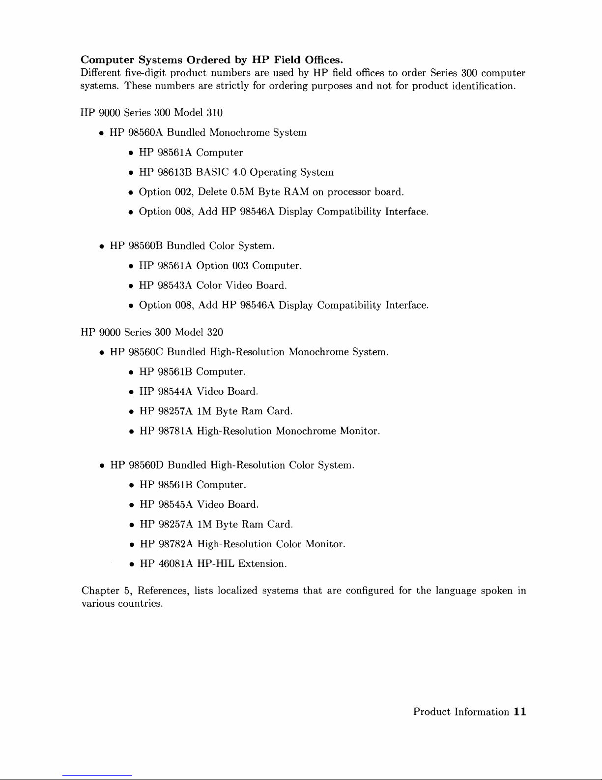
Computer
Systems
Ordered
by
HP
Field
Offices.
Different five-digit
product
nunlbers are used by
HP
field offices
to
order Series 300
computer
systems. These numbers are strictly for ordering purposes
and
not for
product
identification.
HP
9000 Series 300 Model 310
•
HP
98560A Bundled Monochrome System
•
HP
98561A
Computer
•
HP
9861~{B
BASIC 4.0
Operating
System
• Option 002,
Delete 0.5M Byte RAM on processor board.
• Option 008,
Add
HP
98546A Display Compatibility Interface.
•
HP
98560B Bundled Color System.
•
HP
98561A Option 003 Computer.
•
HP
9854:~A
Color Video Board.
• Option 008, Add
HP
98546A Display Compatibility Interface.
HP
9000 Series 300 Model 320
•
HP
98560C Bundled High-Resolution Monochrome System.
•
HP
98561B Computer.
•
HP
98544A Video Board.
•
HP
98257 A
1M
Byte
Ram
Card.
•
HP
98781A High-Resolution Monochrome Monitor.
•
HP
98560D Bundled High-Resolution Color System.
•
HP
98561B Computer.
•
HP
98545A Video Board.
•
HP
98257 A
1M
Byte
Ram
Card.
•
HP
98782A High-Resolution Color Monitor.
•
HP
46081A HP-HIL Extension.
Chapter
5,
References, lists localized systems
that
are configured for
the
language spoken in
various countries.
Product
Information
11
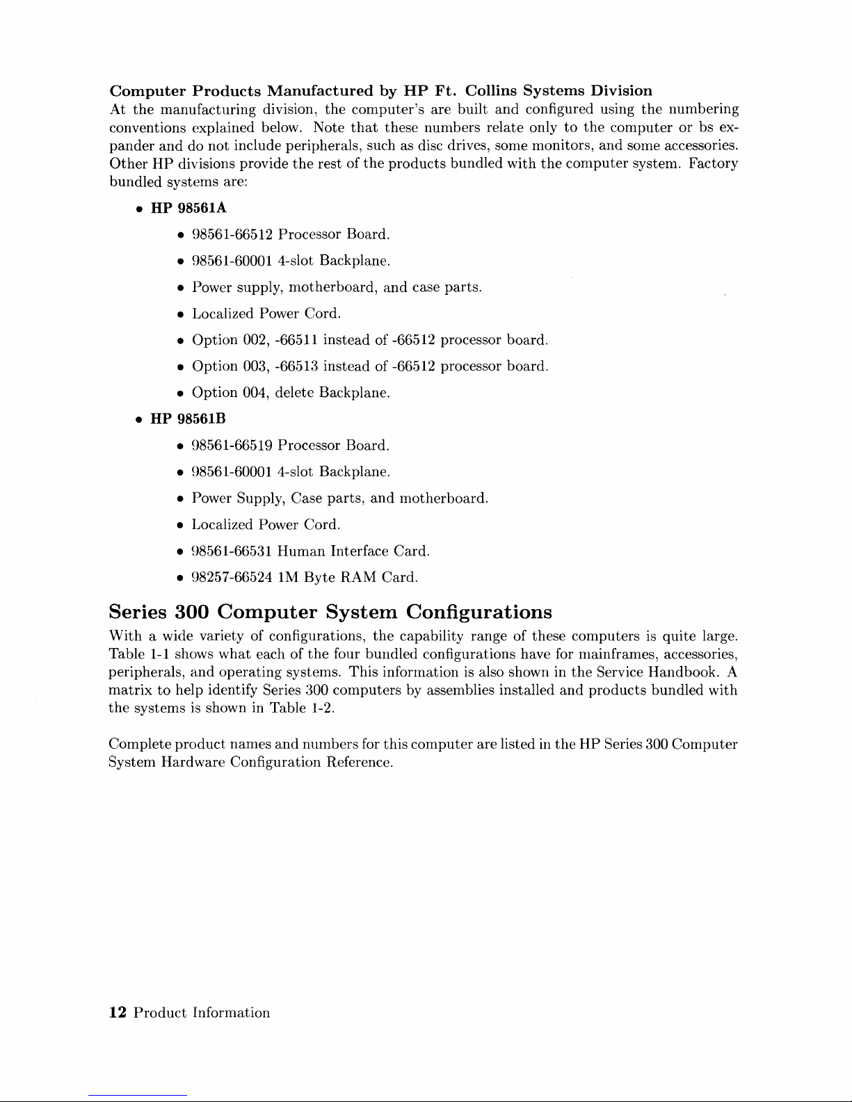
Computer
Products
Manufactured
by
HP
Ft.
Collins
Systems
Division
At
the
manufacturing
division,
the
computer's
are built
and
configured using
the
numbering
conventions explained below. Note
that
these numbers relate only
to
the
computer
or
bs ex-
pander
and
do
not
include peripherals, such as disc drives, some monitors,
and
some accessories.
Other
HP
divisions provide
the
rest
of
the
products
bundled
with
the
computer
system. Factory
bundled
systems are:
•
HP
98561A
• 98561-66512 Processor Board.
• 98561-60001 4-slot Backplane.
• Power supply,
motherboard,
and
case parts.
• Localized Power Cord.
•
Option
002, -66511 instead of -66512 processor board.
•
Option
003, -66513 instead of -66512 processor board.
•
Option
004, delete Backplane .
•
HP
98561B
• 98561-66519 Processor Board.
• 98561-60001 4-slot Backplane.
• Power Supply,
Case
parts,
and
motherboard.
• Localized Power Cord.
• 98561-66531
Human
Interface Card.
• 98257-66524 1M
Byte
RAM
Card.
Series
300
Computer
System
Configurations
With
a wide variety of configurations,
the
capability range
of
these
computers
is
quite
large.
Table
1-1
shows
what
each
of
the
four
bundled
configurations have for nlainframes, accessories,
peripherals,
and
operating
systems.
This
information
is
also shown in
the
Service Handbook. A
matrix
to
help identify Series 300
computers
by assemblies installed
and
products
bundled
with
the
systems
is
shown in Table 1-2.
Complete
product
names
and
numbers for
this
computer
are listed in
the
HP
Series 300
Computer
System
Hardware
Configuration Reference.
12
Product
Information
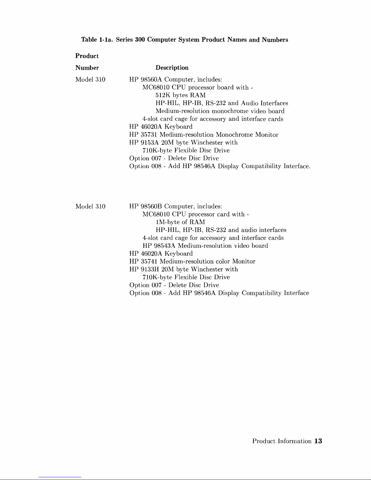
Table
l-la.
Series 300
Computer
System
Product
Names
and
Numbers
Product
Number
Model 310
Model 310
Description
HP
98560A COlnputer, includes:
MC68010
CPU
processor
board
with
512K bytes RAM
HP-HIL, HP-IB, RS-232
and
Audio Interfaces
Medium-resolution monochrome video
board
4-slot
card
cage for accessory
and
interface
cards
HP
46020A
Keyboard
HP
35731 Medium-resolution Monochrome
Monitor
HP
9153A 20M
byte
Winchester with
710K-byte Flexible Disc Drive
Option
007 - Delete Disc Drive
Option
008 -
Add
HP
98546A Display
Compatibility
Interface.
HP
98560B Cornputer, includes:
MC68010
CPU
processor
card
with
1M-byte of RAM
HP-HIL, HP-IB, RS-232
and
audio interfaces
4-slot
card
cage for accessory
and
interface
cards
HP
98543A Medium-resolution video
board
HP
46020A Key
board
HP
35741 Mediulll-resolution color Monitor
HP
9133H 20M
byte
Winchester
with
710K-byte Flexible Disc Drive
Option
007 - Delete Disc Drive
Option
008 -
Add
HP
98546A Display Compatibility Interface
Product
Information
13
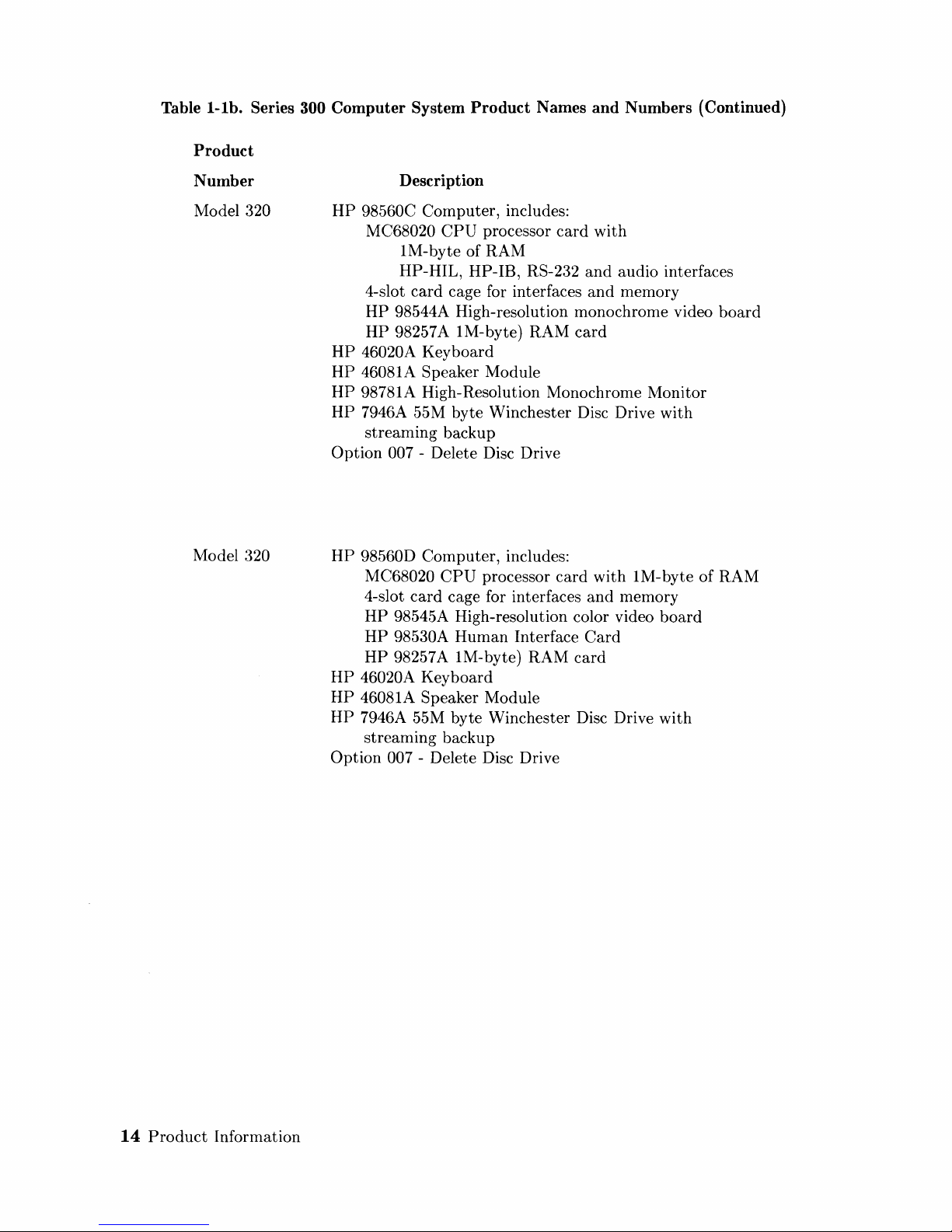
Table
i-lb.
Series 300 Computer System Product Names and Numbers (Continued)
Product
Number
Model 320
Model 320
14
Product
Information
Description
HP
98560C Computer, includes:
MC68020
CPU
processor
card
with
1M-byte of RAM
HP-HIL, HP-IB, RS-232
and
audio interfaces
4-slot
card
cage for interfaces
and
memory
HP
98544A High-resolution monochrorne video
board
HP
98257A 1M-byte) RAM
card
HP
46020A Keyboard
HP
46081A Speaker Module
HP
98781A High-Resolution Monochrome Monitor
HP
7946A 55M byte Winchester Disc Drive with
streaming backup
Option
007 - Delete Disc Drive
HP
98560D Computer, includes:
MC68020
CPU
processor
card
with 1M-byte of RAM
4-slot
card
cage for interfaces
and
memory
HP
98545A High-resolution color video
board
HP
98530A
Human
Interface
Card
HP
98257 A 1M-byte) RAM
card
HP
46020A Keyboard
HP
46081A Speaker Module
HP
7946A 55M byte Winchester Disc Drive with
streaming backup
Option
007 - Delete Disc Drive
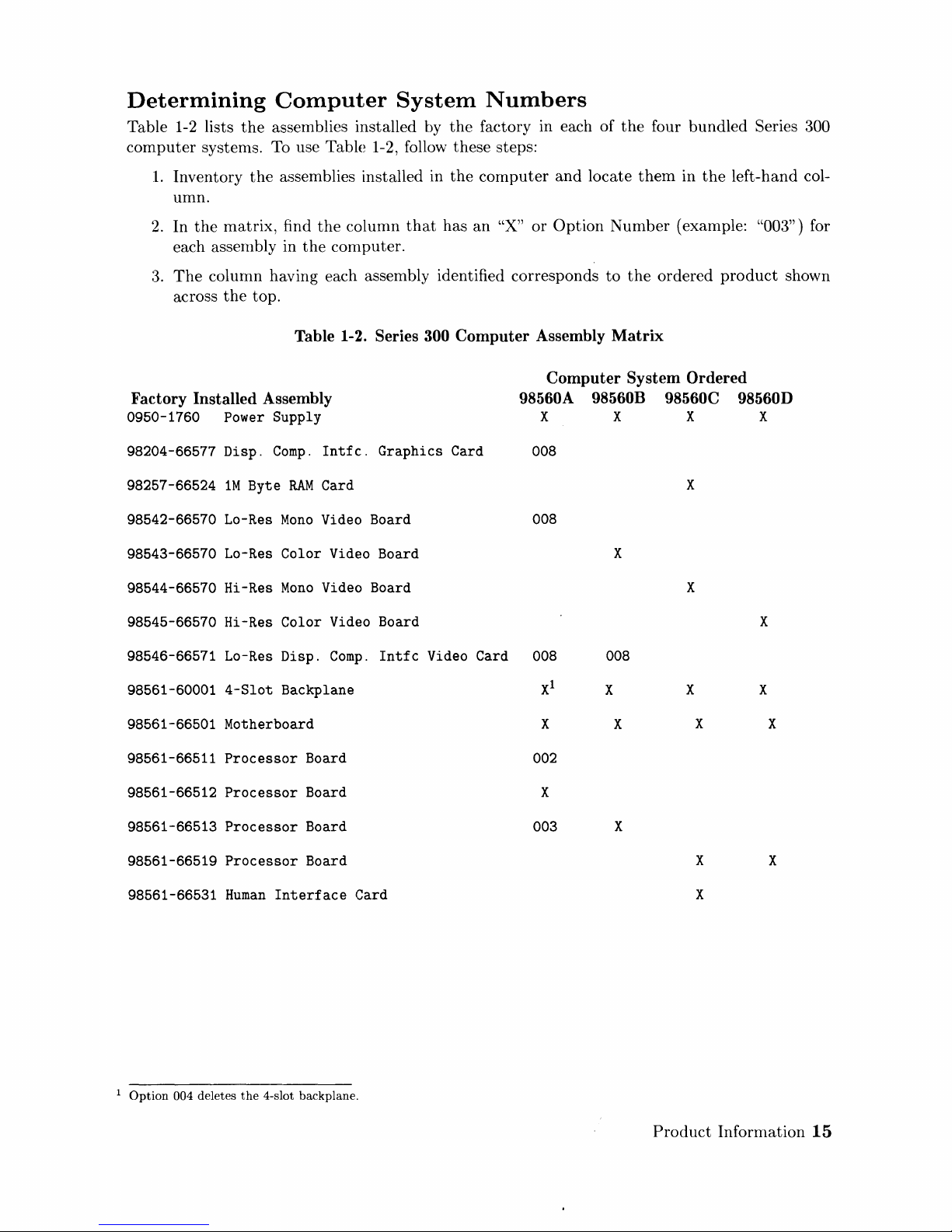
Determining
Table 1-2 lists
computer
1.
Inventory
umn.
2.
In
each assernbly in
:3.
The
across
the
systenls. To use Table 1-2, follow these steps:
the
matrix,
column having each assembly identified corresponds
the
Computer
assemblies installed by
the
assemblies installed in
find
the
column
the
computer.
top.
System
the
the
that
has
Numbers
factory in each of
computer
an
"X"
or
and
locate
Option
the
four
them
Number
to
the
bundled
in
the
Series 300
left-hand col-
(example: "003") for
ordered
product
shown
Table 1-2.
Series 300
Computer
Assembly
Matrix
Computer
Factory
0950-1760 Power Supply X X
98204-66577 Disp.
98257-66524
98542-66570
98543-66570
98544-66570
98545-66570 Hi-Res
98546-66571 Lo-Res Disp.
98561-60001
98561-66501 Motherboard X
98561-66511
Installed
1M
Byte
Lo-Res
Lo-Res
Hi-Res
4-Slot
Processor
Assembly
Compo
Intfc.
RAM
Card
Mono
Video
Color
Mono
Color
Backplane
Video Board X
Video Board X
Video Board X
Compo
Board 002
Graphics
Board
Intfc
Card
Video Card 008 008
98560A
008
008
Xl
98560B
X
X
System
98560C
Ordered
98560D
X X
X
X X
X
X
98561-66512
98561-66513
98561-66519
98561-66531
1
Option
004 deletes
Processor
Processor
Processor
Human
Interface
the
4-slot backplane.
Board X
Board
Board
Card
003
X
X
X
Product
X
Information
15
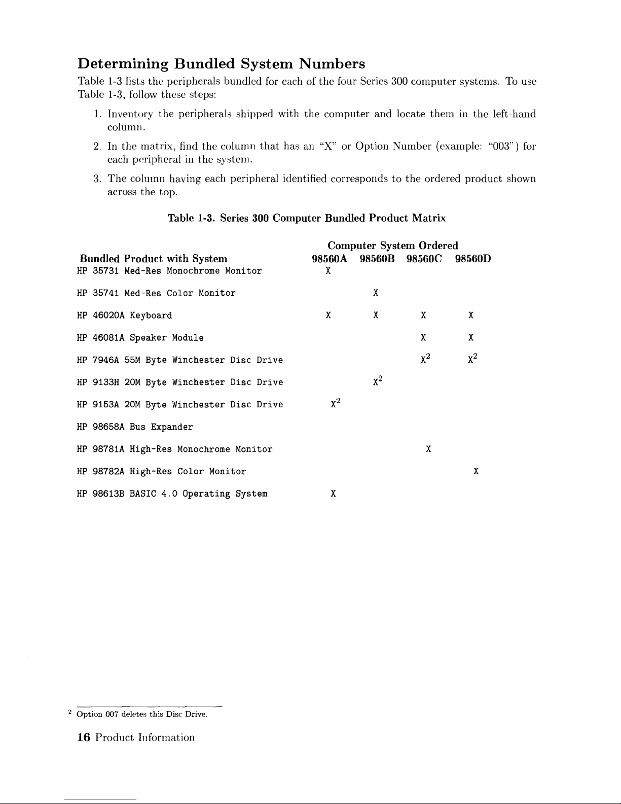
Determining
Table 1-3 lists
Bundled
the
peripherals bundled for each
Table 1-3, follow these steps:
1.
Inventory
the
peripherals
column.
2.
In
the
matrix,
each peripheral in
3.
The
column having each peripheral identified corresponds
across
the
top.
find
the
the
System
shipped
column
systenl.
that
Numbers
of
with
the
has
an
the
four Series 300 cornputer systerns. To use
computer
"X"
or
and
Option
locate
Number
to
the
them
in
the
left-hand
(example: "003") for
ordered
product
shown
Bundled
HP
35731 Med-Res
HP
35741
HP
46020A
HP
46081A
HP
7946A
HP
9133H
HP
9153A
HP
98658A
HP
98781A
HP
98782A
HP
98613B
Table 1-3. Series
Product
Med-Res
with
System
Monochrome
Color
Monitor
Monitor
Keyboard
Speaker
55M
20M
20M
Bus
High-Res
Module
Byte Winchester Disc Drive
Byte Winchester Disc Drive
Byte Winchester Disc Drive
Expander
Monochrome
High-Res Color Monitor
BASIC
4.0
Operating
300
Monitor
System
Computer
98560A 98560B 98560C 98560D
Bundled
Product
Computer
X
X
X X
X
System
Matrix
Ordered
X
X
2
X
X
X
X
X
2
Option
007 deletes
16
Product
this
Disc Drive.
Infonnation
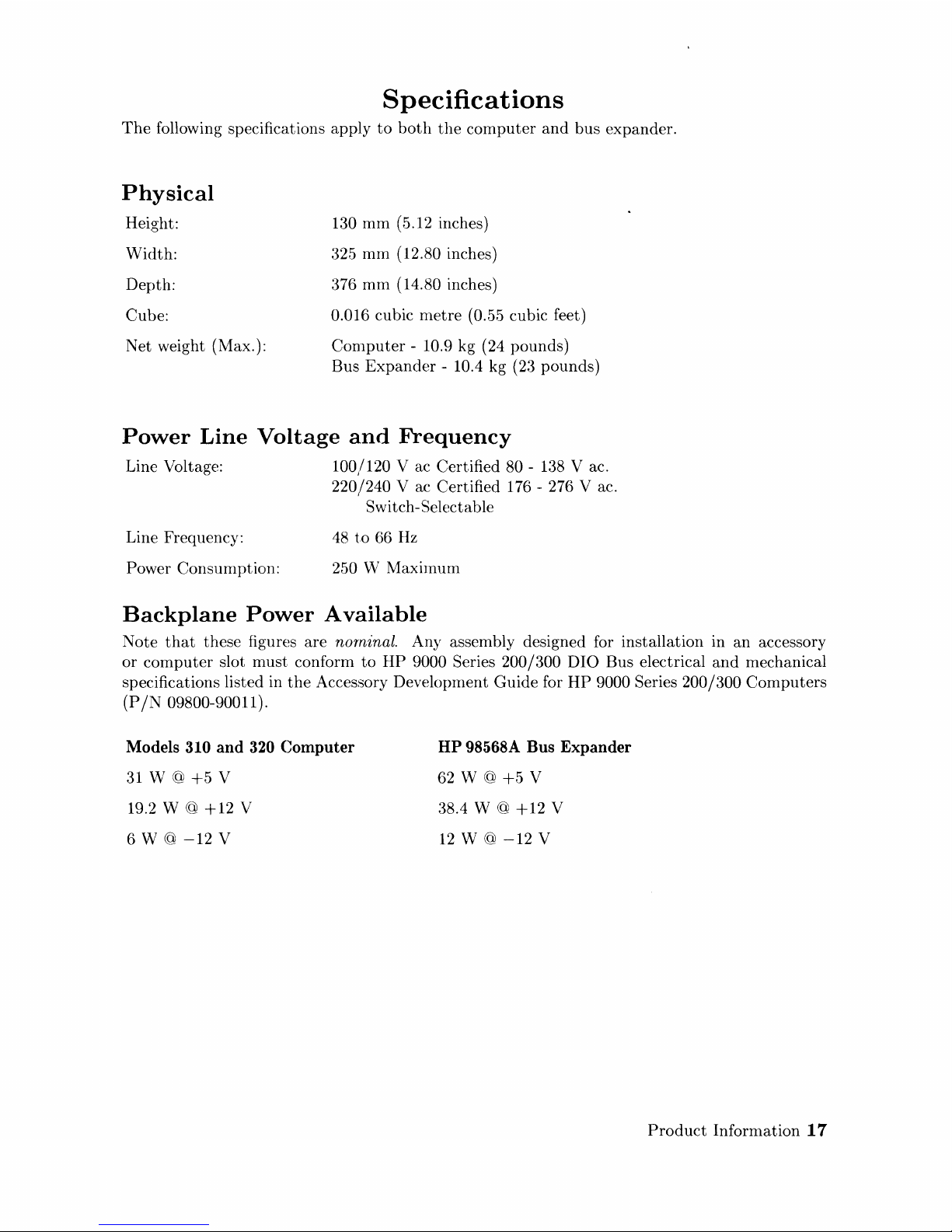
Specifications
The
following specifications apply
to
both
the
computer
and
bus
expander.
Physical
Height:
Width:
Depth:
Cube:
Net weight (Max.):
130
mm
(5.12 inches)
325
mm
(12.80 inches)
376
mm
(14.80 inches)
0.016 cubic
metre
(0.55 cubic feet)
Computer
- 10.9 kg (24 pounds)
Bus
Expander
- 10.4 kg (23 pounds)
Power
Line
Voltage
and
Frequency
Line Voltage:
Line Frequency:
Power Consumption:
100/120 V ac Certified 80 -
138
V ac.
220/240 V ac Certified 176 - 276 V ac.
Switch-Selectable
48
to
66
Hz
250 W Maximum
Backplane
Power
Available
Note
that
these figures are norninal. Any assembly designed for installation in
an
accessory
or
computer
slot
must
conform
to
HP
9000 Series 200/300
DIO
Bus electrical
and
mechanical
specifications listed in
the
Accessory Development Guide for
HP
9000 Series 200/300
Computers
(P
/N
09800-90011).
Models 310 and 320 Computer
31
W @
+5
V
19.2 W @
+12
V
6 W
@
-12
V
HP 98568A Bus Expander
62 W @
+5
V
38.4 W @
+12
V
12
W @
-12
V
Product
Information
17
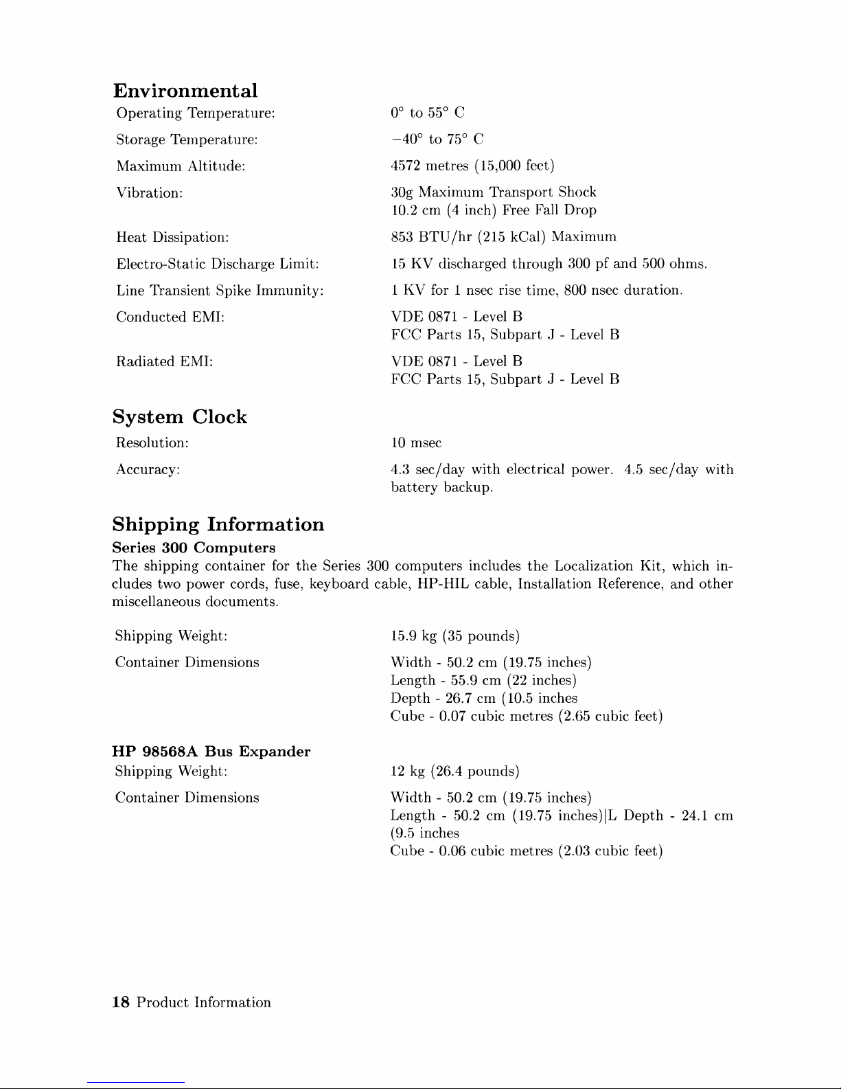
Environmental
Operating
Temperature:
Storage Ternperature:
Maximum Altitude:
Vibration:
Heat
Dissipation:
Electro-Static Discharge Limit:
Line Transient
Spike Immunity:
Conducted
EMI:
Radiated
EMI:
System
Clock
Resolution:
Accuracy:
Shipping
Information
Series
300
Computers
0°
to
55° C
-40°
to
75° C
4572 metres (15,000 feet)
30g Maximum
Transport
Shock
10.2
cm (4 inch) Free Fall Drop
853
BTU
/hr
(215 kCal) Maximum
15
KV discharged
through
300
pf
and
,500
ohms.
1
KV
for 1 nsec rise time, 800 nsec
duration.
VDE
0871 - Level B
FCC
Parts
15,
Subpart
J - Level B
VDE
0871 - Level B
FCC
Parts
15,
Subpart
J - Level B
10
msec
4.3
sec/day
with
electrical power. 4.5
sec/day
with
battery
backup.
The
shipping container for
the
Series 300
computers
includes
the
Localization Kit, which in-
cludes two power cords, fuse, keyboard cable, HP-HIL cable, Installation Reference,
and
other
miscellaneous documents.
Shipping Weight:
Container
Dimensions
HP
98568A
Bus
Expander
Shipping Weight:
Container
Dimensions
18
Product
Information
15.9 kg (35 pounds)
Width
- 50.2
cm
(19.75 inches)
Length - 55.9
cm
(22 inches)
Depth
- 26.7
cm
(10.5 inches
Cube
- 0.07 cubic metres
(2J>5
cubic feet)
12
kg ( 26.4 pounds)
Width
- 50.2
cm
(19.75 inches)
Length -
50.2 cm (19.75 inches)IL
Depth
- 24.1 cm
(9.5 inches
Cube
- 0.06 cubic metres (2.03 cubic feet)
Service
Support
Repair
Philosophy
Field
Repair
Philosophy for
the
Series 300
Computers
and
the
HP
98568 Bus
Expander
is
assembly level.
This
Ineans
that
when a failure occurs,
the
problem is diagnosed
to
the
assembly
having
the
failed
part.
That
assembly is
then
replaced. Replacement assemblies are available
through
local
HP
Sales
and
Service Offices.
SOIne
assemblies may
be
replaced
with
rebuilt ones instead
of
new ones.
Other
assemblies are
only available as new ones. Refer
to
the
Series 300 Service Handbook,
Chapter
8, Replaceable
Parts,
for infornlation on replacement
parts.
Schematics
In
support
of
the
repair philosophy,
this
manual
contains information
to
the
assembly level.
Schematics are
not
available for these products.
Supported
Configurations
Only Series 300
Conlputer
Systems
with
Hewlett-Packard approved
parts,
accessories, peripher-
als,
operating
systems
and
application programs are
supported
by Hewlett-Packard. Any Series
300
Computer
System with
other
than
HP
approved
hardware
or
software connected
or
installed
must
have
the
non-
HP
approved
hardware
and
software removed by
the
customer
before On-Site
or
Service
Center
repair
is
accomplished.
Hewlett
Packard
Support
Hewlett-Packard provides service
support
in
three
ways:
• On-Site Repair.
• Service
Center
Repair.
•
Customer
Repair.
Each of these
are
explained in
the
sections below.
On-Site
Repair
For On-Site Repair,
an
HP
Customer
Engineer goes
to
the
customers site, troubleshoots,
and
repairs
the
hardware
to
the
assembly level.
The
defective assembly is replaced
with
a new
or
rebuilt assembly.
This
service
is
available
through
a service
contract
or
a time-and-materials
basis.
Hewlett-Packard
Service
Center
Repair
The
customer
returns
the
defective
product
to
the
nearest
HP
Repair Center. An
HP
Customer
Engineer repairs
the
product
to
the
assembly level in
the
same
manner
as On-Site Repair.
Upon
being repaired,
the
product
is
returned
to
the
customer.
Contact
your nearest
HP
Sales
and
Service Office for
the
location of
the
HP
Repair Center, typical
turn-around
times,
and
shipping
instructions.
Product
Information
19

Customer
Repair
Customers
have
the
option
of repairing
their
own
HP
computer
products.
Contact
your nearest
HP
Sales
and
Service Office for information concerning service training, special tools
and
test
equipment,
and
spare
parts.
Hewlett-Packard offers a
Customer
Cooperative
Support
Prograrn
to
assist custorners in main-
taining
their
HP
cornputer products. A variety of technical services
and
information are avail-
able.
Your local HP Sales
and
Service
can
provide you
with
information
about
the
Cooperative
Support
Program.
20
Product
lnformation
 Loading...