

HP 9000 318M Service Information Manual
Service Information Manual
HP
9000 Series
300
Computers
Models
330/350
HP
Part
Number 98562-90030
FIIOW
HEWLETT
a!1!.II
PACKARD
Hewlett-Packard
Company
3404
East Harmony
Road.
Fort
CoIHns.
Colorado 80525

NOTICE
The information contained in this document is subject
to
change without notice.
HEWLETI-PACKARD
MAKES NO WARRANTY OF ANY KIND WITH REGARD TO THIS MANUAL, INCLUDING, BUT NOT LIMITED TO, THE IMPLIED WARRANTIES
OF MERCHANTABILITY
AND FITNESS FOR A PARTICULAR PURPOSE. Hewlett-Packard shall not be liable
for
errors contained herein
or
direct, indirect, special,
incidental
or
consequential damages in connection with the furnishing, performance,
or
use
of
this material.
WARRANTY
A copy
of
the specific warranty terms applicable
to
your Hewlett-Packard product and replacement parts can be obtained from your local Sales and Service Office.
Copyright 1986 Hewlett-Packard Company
This document contains proprietary information which is protected by copyright. All rights are reserved.
No
part
of
this document may be photocopied, reproduced
or
translated
to
another language without the prior written consent
of
Hewlett-Packard Company. The information contained in this document is subject
to
change without
notice.
Restricted Rights Legend
Use, duplication
or
disclosure by the Government is subject
to
restrictions as set forth in paragraph (b)(3)(B)
of
the Rights
In
Technical Data and Software clause in
DAR
7-104.9(a).
Copyright 1980, 1984, AT&T, Inc.
Copyright 1979, 1980, 1983, The Regents
of
the University
of
California.
This software and documentation is based in part on the Fourth Berkeley Software Distribution under license from the Regents
of
the University
of
California.
ii

Printing
History
New
editions of this Jnanual will incorporate all material
updated
since
the
previous edition.
Update packages may
be
issued between editions
and
contain replacement
and
additional pages
to
be
merged into
the
manual by
the
user. Each
updated
page will
be
indicated by a revision
date
at
the
bottom
of
the
page. A vertical
bar
in
the
margin indicates
the
changes on each page.
Note
that
pages which are rearranged
due
to
changes on a previous page are not considered
revised.
The
manual printing
date
and
part
number indicate its
current
edition.
The
printing
date
changes when a new edition
is
printed. (Minor corrections
and
updates
which
are
incorporated
at
reprint do not cause
the
date
to
change.)
The
manual
part
number changes when extensive
technical ehanges are incorporated.
December 1986 ... Edition 1
Printing
History iii
Notices
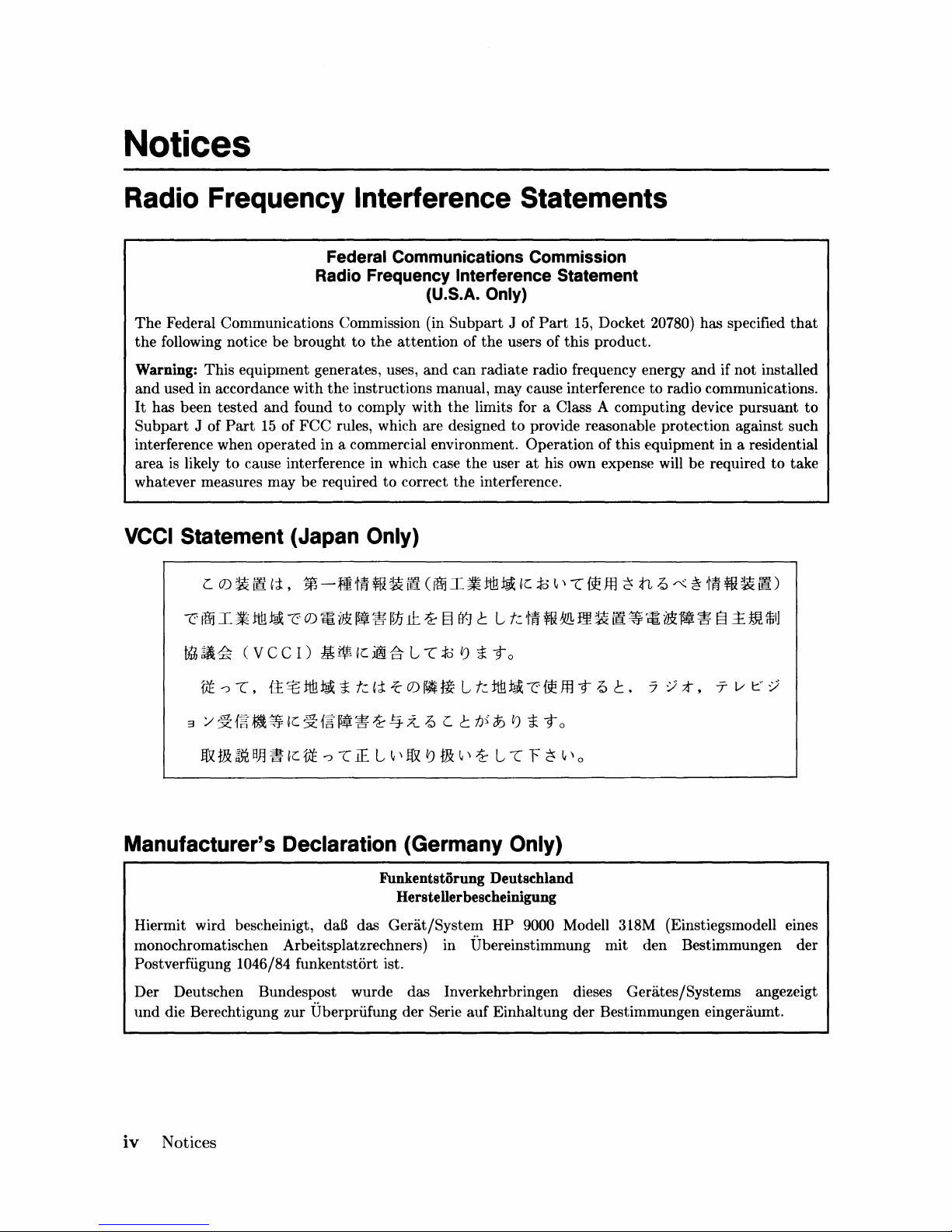
Radio Frequency Interference Statements
Federal Communications Commission
Radio Frequency Interference Statement
(U.S.A. Only)
The
Federal Communications Commission (in Subpart J of
the
following notice be brought to
the
attention of
the
Part
15,
Docket 20780) has specified
users of this product.
that
Warning: This equipment generates, uses,
and
used in accordance with
It
has been tested
Subpart
J of
Part
and
15
the
instructions manual, may cause interference to radio communications.
found to comply with the limits for a Class A computing device pursuant to
of
FCC
rules, which are designed
and
can radiate radio frequency energy
interference when operated in a commercial environment.
area
is
likely
to
cause interference in which case
whatever measures may be required
to
correct
the
the
interference.
VCCI Statement (Japan Only)
L
O)~
@
,j:,
~-ft'tff~~@
~~I~~~~O).~.~~~~§~~LkM~~m~@~.~.~~~m~
thh
~~
(V
3
fJt
/I
5t
~
m m
--:>
""[,
ft~ ~ ~
eel)
{t'::8
B~ ~ ~c
~
c
tili
5t
fJt
£~
~
i
f§"
~! ~ ~
-:>
""[
~c
~
t:
,j:
1£
L
(~I~tili~
1:5-
L
""[
is
~
i-
0)
~
~
L
13-.:Z
~ L ~
~
'I
~
~ m ~
'I
i
t:
fyi
~
and
if not installed
to
provide reasonable protection against such
Operation of this equipment in a residential
user
at
his own expense will be required to take
~c
is
~'I""[
~m
~
tL
~«~
'tff~~i!i)
-to
tili
~ ~ ~
£t
~
L
""[
i -t 0
F
~
ffl
~
'I 0
-t
~
~.
::;:/;t,
T v
1::"
:/
Manufacturer's Declaration (Germany Only)
Hiermit wird bescheinigt,
monochromatischen Arbeitsplatzrechners) in Ubereinstimmung mit den Bestimmungen der
Postverfiigung
Der Deutschen Bundespost wurde das Inverkehrbringen dieses Gerates/Systems angezeigt
und
die Berechtigung zur Uberpriifung der Serie
iv
Notices
1046/84 funkentstort ist.
daB
Funkentstorung Deutschland
HersteUerbescheinigung
das
Gedit/System
HP
auf
Einhaltung der Bestimmungen eingeraumt.
9000 Modell 318M (Einstiegsmodell eines
Safety Considerations
WARNINGs, CAUTIONs, and Notes
WARNINGS, CAUTIONS
and
Notes
are
used in
this
manual
to
alert
users
to
important
situ-
ations.
They
are
used as follows:
• WARNINGS contain information which, if
not
observed, could result in injury
to
person-
nel
or
loss of life.
•
CAUTIONS
contain information which if
not
observed, could result in
damage
to
or
destruction of equipment.
• Notes contain information
that
will assist you in accomplishing
the
job.
WARNING
The power supply is hazardous to personnel. Extreme care must be
taken when connecting voltmeter probes to the test points. Turn
otT
the unit and remove the power cord before connecting or removing
test probes.
CAUTION
Integrated circuits on PC boards are susceptible to damage
by
electrostatic discharge. Extreme care must be taken when handling printed
circuit boards. Use an Anti-static Workstation.
Note
Hewlett-Packard
supports
field
repair
of
these
products
only
to
the
board
or
assembly level.
Component
level information
and
repair is
not
within
the
scope of
this
manual,
nor
available.
Notices
v

vi
Notices
Information
Locator
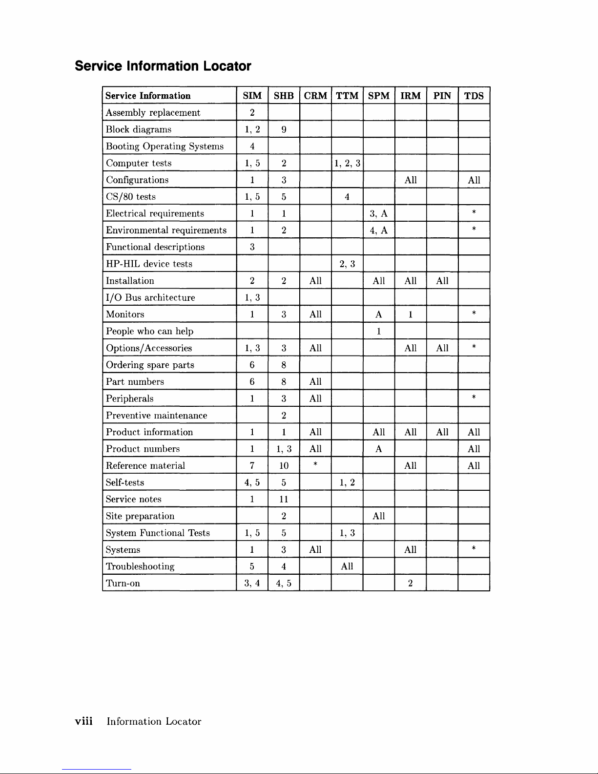
Finding Service Information
On
the
next
page
is
a Service Information Locator.
It
shows where
to
find a variety
of
subjects
dealing with servicing these
products.
To
l:lse
this
table, first find
the
type
of
information you
need
to
reference in
the
left-hand column. Next, move
to
the
right in
that
row
to
a referenced
chapter
number. Last, move
up
the
column
with
the
information's
referenced
chapter
to
the
top. Across
the
top
are
manual
titles
and
part
numbers
that
have
the
information documented.
Chapter
identifiers in
the
Locator
use
the
following codes:
Chapter
Number:
Appendices:
Numbers, such as
2.
Inclusive
chapters,
such as 4-6.
Letters, such as A for
Appendix
A.
Entire
Manual: All
Varies:
* (Check Table
of
Contents
or
Index.)
In some cases, two
or
more references will
be
shown for a given
infonnation
type. You should
check all references
to
be
sure
you get
the
specific information you need.
For example, suppose you need
to
find
out
what
the
Repair
Philosophy
is
for
the
Model 318M
Workstation's
SPU. Locating "Repair Philosophy" in
the
left-hand column,
and
moving
to
the
right in
that
row, you'll notice
that
this
information
is
in
"Chapter
I"
of
a manual.
At
the
top
of
this
column
is
the
nlanual's
abbreviated
title.
Chapter
7 in
this
manual
lists
manual
titles
and
part
nunlbers for service information.
Service Information Locator
Manuals identified in
this
locator
are
abbreviated
by
their
initials:
81M Service Information Manual
8HB
Service
Handbook
CRM Configuration Reference Manual
TTM: Series 300 Test Tools Manual
8PM
Site
Preparation
Manual
IRM
Installation
Reference
Manual
PIN
Product
Installation
Note
TD8
Technical
Data
Sheet/Price
List
Information
Locator
vii
Service Information Locator
Service Information SIM
SHB
CRM TTM
SPM
IRM
PIN
TDS
Assembly replacement 2
Block diagrams
1,2
9
Booting
Operating
Systems 4
Computer
tests
1,5
2
1,
2,
3
Configurations 1
3
All
All
CS/80
tests
1,5
5
4
Electrical requirements 1
1 3, A
*
Environmental requirements 1
2
4,
A
*
Functional descriptions
3
HP-HIL device
tests
2,
3
Installation 2
2 All All All All
I/O
Bus architecture
1,3
Monitors 1
3
All
A 1
*
People who
can
help
1
Options / Accessories
1,3
3
All All All
*
Ordering spare
parts
6
8
Part
numbers 6
8
All
Peripherals
1
3
All
*
Preventive maintenance
2
Product
information 1
1 All All All All
All
Product
numbers 1
1,3
All A
All
Reference material
7 10
*
All
All
Self-tests
4,
5
5
1,2
Service notes
1
11
Site
preparation
2 All
System Functional Tests
1,5
5
1,3
Systems 1
3
All All
*
Troubleshooting 5 4 All
Turn-on
3, 4
4,
5 2
viii
Information
Locator
Table of Contents
Service/Hardware Information
Chapter
1:
Product
Information
Introdllction.
. . . . . . . . . . . . . . . . . . . . . . . . . . . . . . . . . . . . . . . . . . . . . . . . . . . . . . . . . . . . . . .
..
1
Workstations
. . . . . . . . . . . . . . . . . . . . . . . . . . . . . . . . . . . . . . . . . . . . . . . . . . . . . . . . . . .
..
1
Systenl
Configurations.
. . . . . . . . . . . . . . . . . . . . . . . . . . . . . . . . . . . . . . . . . . . . . . . . . .
..
1
FeatlLres . . . . . . . . . . . . . . . . . . . . . . . . . . . . . . . . . . . . . . . . . . . . . . . . . . . . . . . . . . . . . . . . . . .
..
3
Performance.
. . . . . . . . . . . . . . . . . . . . . . . . . . . . . . . . . . . . . . . . . . . . . . . . . . . . . . . . . . . . . . .
..
4
Hard"ware . . . . . . . . . . . . . . . . . . . . . . . . . . . . . . . . . . . . . . . . . . . . . . . . . . . . . . . . . . . . . . . . . .
..
5
CPU
_.
MC68020
..........................................................
5
Bus
Architecture
..........................................................
5
Motherboard/Backplane.
. . . . . . . . . . . . . . . . . . . . . . . . . . . . . . . . . . . . . . . . . . . . . . . .
..
6
]{ey
boards
. . . . . . . . . . . . . . . . . . . . . . . . . . . . . . . . . . . . . . . . . . . . . . . . . . . . . . . . . . . . .
..
7
HP
9000
Hardware
Compatibility
. . . . . . . . . . . . . . . . . . . . . . . . . . . . . . . . . . . . . . . . .
..
7
Operating
Systerns . . . . . . . . . . . . . . . . . . . . . . . . . . . . . . . . . . . . . . . . . . . . . . . . . . . . . . . . . .
..
9
IIP-UX 5.2
...............................................................
9
]3ASIC~
5.0
...............................................................
9
]::>ascal
:3.2
. . . . . . . . . . . . . . . . . . . . . . . . . . . . . . . . . . . . . . . . . . . . . . . . . . . . . . . . . . . . . .
..
9
Software Co:mpatibility
....
. . . . . . . . . . . . . . . . . . . . . . . . . . . . . . . . . . . . . . . . . . . . . .
..
9
Product
Identification . . . . . . . . . . . . . . . . . . . . . . . . . . . . . . . . . . . . . . . . . . . . . . . . . . . . . .
..
10
Product
Identification Terms . . . . . . . . . . . . . . . . . . . . . . . . . . . . . . . . . . . . . . . . . . . .
..
10
Serial
Numbers
..........................................................
10
Hardware
Terminology
...................................................
11
Software Terminology
....................................................
12
Hardware
Support
Documentation
....
. . . . . . . . . . . . . . . . . . . . . . . . . . . . . . . . . . . . . . .
..
12
Service
Information
Manual . . . . . . . . . . . . . . . . . . . . . . . . . . . . . . . . . . . . . . . . . . . . .
..
13
Service
Handbook.
. . . . . . . . . . . . . . . . . . . . . . . . . . . . . . . . . . . . . . . . . . . . . . . . . . . . .
..
14
Test Tools
Manual
.......................................................
15
Service
Notes.
. . . . . . . . . . . . . . . . . . . . . . . . . . . . . . . . . . . . . . . . . . . . . . . . . . . . . . . . .
..
15
Installation
Notes.
. . . . . . . . . . . . . . . . . . . . . . . . . . . . . . . . . . . . . . . . . . . . . . . . . . . . .
..
15
Series 300 Configuration Reference Manual
..................................
16
Site
Preparation
Manual.
. . . . . . . . . . . . . . . . . . . . . . . . . . . . . . . . . . . . . . . . . . . . . . .
..
16
Installation
Reference
....................................................
18
Specifications. . . . . . . . . . . . . . . . . . . . . . . . . . . . . . . . . . . . . . . . . . . . . . . . . . . . . . . . . . . . . .
..
19
:Electrical . . . . . . . . . . . . . . . . . . . . . . . . . . . . . . . . . . . . . . . . . . . . . . . . . . . . . . . . . . . . .
..
19
Environnlental . . . . . . . . . . . . . . . . . . . . . . . . . . . . . . . . . . . . . . . . . . . . . . . . . . . . . . . . .
..
19
Electromagnetic Interference
..............................................
20
Regulatory
Requirements
.................................................
20
:Physical
....................
. . . . . . . . . . . . . . . . . . . . . . . . . . . . . . . . . . . . . . . . . .
..
20
Shipping
Information.
. . . . . . . . . . . . . . . . . . . . . . . . . . . . . . . . . . . . . . . . . . . . . . . . . .
..
20
Model 350 Processor
Board
...............................................
21
Model 330 Processor
Board
...............................................
22
Memory
................................................................
22
DIO-II
I/O
Bus
..........................................................
23
System
Interface
Board
. . . . . . . . . . . . . . . . . . . . . . . . . . . . . . . . . . . . . . . . . . . . . . . . .
..
23
Table
of
Contents
ix
HP-HIL
and
Video Accessories
............................................
24
Hewlett-Packard
Support
.....................................................
25
Repair
Philosophy
.......................................................
25
Repair
Services . . . . . . . . . . . . . . . . . . . . . . . . . . . . . . . . . . . . . . . . . . . . . . . . . . . . . . . .
..
25
Hardware
Support
Services
................................................
26
Operating
Systems
Support
. . . . . . . . . . . . . . . . . . . . . . . . . . . . . . . . . . . . . . . . . . . . .
..
26
Chapter
2:
Assembly Replacement
Introduction
.............................................
, . . . . . . . . . . . . . . . . .
..
27
Tools Required
..........................................................
27
Access Flow
Chart
. . . . . . . . . . . . . . . . . . . . . . . . . . . . . . . . . . . . . . . . . . . . . . . . . . . . .
..
27
Parts
DiagraIns . . . . . . . . . . . . . . . . . . . . . . . . . . . . . . . . . . . . . . . . . . . . . . . . . . . . . . . . . . . .
..
30
Safety
Precautions
...........................................................
32
Electrical
Precautions
....................................................
32
System Board
Installation.
. . . . . . . . . . . . . . . . . . . . . . . . . . . . . . . . . . . . . . . . . . . . . .
..
32
Electro-Static
Discharge
Precautions
.......................................
33
Assembly Replacement
Procedures
.............................................
34
Overview
...............................................................
34
Fllse
....................................................................
35
HP-HIL
Devices
.........................................................
35
Systenl Bus
....
. . . . . . . . . . . . . . . . . . . . . . . . . . . . . . . . . . . . . . . . . . . . . . . . . . . . . . .
..
35
Processor
Board
...
. . . . . . . . . . . . . . . . . . . . . . . . . . . . . . . . . . . . . . . . . . . . . . . . . . . .
..
36
Video
Boards.
. . . . . . . . . . . . . . . . . . . . . . . . . . . . . . . . . . . . . . . . . . . . . . . . . . . . . . . . .
..
36
Interface
Cards
. . . . . . . . . . . . . . . . . . . . . . . . . . . . . . . . . . . . . . . . . . . . . . . . . . . . . . . .
..
36
Add-On
Boards.
. . . . . . . . . . . . . . . . . . . . . . . . . . . . . . . . . . . . . . . . . . . . . . . . . . . . . . .
..
37
D I
0 Accessory
Cards.
. . . . . . . . . . . . . . . . . . . . . . . . . . . . . . . . . . . . . . . . . . . . . . . . . .
..
38
Power Supply
...........................................................
39
Top
Cover
..............................................................
41
Front
Panel
..
. . . . . . . . . . . . . . . . . . . . . . . . . . . . . . . . . . . . . . . . . . . . . . . . . . . . . . . . .
..
43
Fans
...................................................................
44
DIO
Card
Cages.
. . . . . . . . . . . . . . . . . . . . . . . . . . . . . . . . . . . . . . . . . . . . . . . . . . . . . .
..
45
DIO Backplane
..........................................................
47
Fan Housing. . . . . . . . . . . . . . . . . . . . . . . . . . . . . . . . . . . . . . . . . . . . . . . . . . . . . . . . . . .
..
48
Motherboard
. . . . . . . . . . . . . . . . . . . . . . . . . . . . . . . . . . . . . . . . . . . . . . . . . . . . . . . . . .
..
4~8
Card
Guides
............................................................
50
Chapter
3:
Functional
Description
Introduction
.................................................................
51
Computer
Overview
......................................................
51
Expander
Overview
......................................................
51
Computer
Architecture
...................................................
51
Computer
Packaging
.....................................................
54
System
Implementation.
. . . . . . . . . . . . . . . . . . . . . . . . . . . . . . . . . . . . . . . . . . . . . . . .
..
54
Unsupported
Accessories
..................................................
57
Model
350 Processor Board
...............................................
57
Model
3:~0
Processor
Board
...............................................
57
Model
350
System
Bus
...................................................
57
Menlory Boards
.........................................................
57
System Interface
Board.
. . . . . . . . . . . . . . . . . . . . . . . . . . . . . . . . . . . . . . . . . . . . . . . .
..
59
Monitor
Compatibility.
. . . . . . . . . . . . . . . . . . . . . . . . . . . . . . . . . . . . . . . . . . . . . . . . .
..
59
x Table
of
Contents
Direct-Connect
Expanders
................................................
60
DIO
Adapters
...........................................................
62
Power
Supply
...............................................................
64
Introduction
.............................................................
64
Inpllt
Section.
. . . . . . . . . . . . . . . . . . . . . . . . . . . . . . . . . . . . . . . . . . . . . . . . . . . . . . . . .
..
67
Rectification
and
Switching Control
Circuits
................................
68
Power Supply Regulators
.................................................
68
Protection
and
Reset Circuits
.............................................
69
Power
Distribution
.......................................................
69
Motherboarcl . . . . . . . . . . . . . . . . . . . . . . . . . . . . . . . . . . . . . . . . . . . . . . . . . . . . . . . . . . . . . .
..
71
Introcluction. . . . . . . . . . . . . . . . . . . . . . . . . . . . . . . . . . . . . . . . . . . . . . . . . . . . . . . . . . .
..
71
F'unctions . . . . . . . . . . . . . . . . . . . . . . . . . . . . . . . . . . . . . . . . . . . . . . . . . . . . . . . . . . . . .
..
71
HP
98242
DIO
Backplane
Board.
. . . . . . . . . . . . . . . . . . . . . . . . . . . . . . . . . . . . . . . . . . . .
..
73
Introduction.
. . . . . . . . . . . . . . . . . . . . . . . . . . . . . . . . . . . . . . . . . . . . . . . . . . . . . . . . . .
..
73
F'unctions . . . . . . . . . . . . . . . . . . . . . . . . . . . . . . . . . . . . . . . . . . . . . . . . . . . . . . . . . . . . .
..
73
Model
~{50
Processor
Board
...................................................
74
Introciuction. . . . . . . . . . . . . . . . . . . . . . . . . . . . . . . . . . . . . . . . . . . . . . . . . . . . . . . . . . .
..
74
Central
Processing
Unit
..................................................
74
C:;oprocessor . . . . . . . . . . . . . . . . . . . . . . . . . . . . . . . . . . . . . . . . . . . . . . . . . . . . . . . . . . .
..
74
rviemory
Management
Unit
................................................
74
Translation
Tables
..
. . . . . . . . . . . . . . . . . . . . . . . . . . . . . . . . . . . . . . . . . . . . . . . . . . .
..
77
Translation
Lookaside Buffer . . . . . . . . . . . . . . . . . . . . . . . . . . . . . . . . . . . . . . . . . . . .
..
77
(~ache
..................................................................
77
Boot
ROM
and
Self-Test LEDs . . . . . . . . . . . . . . . . . . . . . . . . . . . . . . . . . . . . . . . . . .
..
78
Model
~3:30
Processor
Board
...................................................
79
lntro(iuction.
. . . . . . . . . . . . . . . . . . . . . . . . . . . . . . . . . . . . . . . . . . . . . . . . . . . . . . . . . .
..
79
Central
Processing Unit
..................................................
79
IV1emory
~anagelnent
Unit.
. . . . . . . . . . . . . . . . . . . . . . . . . . . . . . . . . . . . . . . . . . . . .
..
79
On-Board
RAM
.........................................................
80
Bus
Architecture.
. . . . . . . . . . . . . . . . . . . . . . . . . . . . . . . . . . . . . . . . . . . . . . . . . . . . . . . . . .
..
84
lntro(iuction
.............................................................
84
Model
:350
System Bus
...................................................
84
DIO
and
DIO-II Bus
.....................................................
84
RAM[
Boards
................................................................
86
Introduction.
. . . . . . . . . . . . . . . . . . . . . . . . . . . . . . . . . . . . . . . . . . . . . . . . . . . . . . . . . .
..
86
RAM
Architecture
.......................................................
86
RAM Address
and
Size . . . . . . . . . . . . . . . . . . . . . . . . . . . . . . . . . . . . . . . . . . . . . . . . .
..
90
]=tAM
(~lock
. . . . . . . . . . . . . . . . . . . . . . . . . . . . . . . . . . . . . . . . . . . . . . . . . . . . . . . . . . .
..
90
Board
Select
............................................................
90
\.\-7
rite (:ycle . . . . . . . . . . . . . . . . . . . . . . . . . . . . . . . . . . . . . . . . . . . . . . . . . . . . . . . . . . .
..
90
Read
Cycles.
. . . . . . . . . . . . . . . . . . . . . . . . . . . . . . . . . . . . . . . . . . . . . . . . . . . . . . . . . .
..
90
l\1odel
:350
Systenl
Bus
Data
Transfers.
. . . . . . . . . . . . . . . . . . . . . . . . . . . . . . . . . . .
..
90
RAM Configuration
......................................................
91
Video I30ar(is . . . . . . . . . . . . . . . . . . . . . . . . . . . . . . . . . . . . . . . . . . . . . . . . . . . . . . . . . . . . . .
..
93
Intro(iuction . . . . . . . . . . . . . . . . . . . . . . . . . . . . . . . . . . . . . . . . . . . . . . . . . . . . . . . . . . .
..
93
'Vi(ieo
RAM
. . . . . . . . . . . . . . . . . . . . . . . . . . . . . . . . . . . . . . . . . . . . . . . . . . . . . . . . . . .
..
96
Color
~/Iapping
..........................................................
96
Display
Controller
.......................................................
96
Frame
Buffer Controller
..................................................
97
Video
Output
...........................................................
97
Table of
Contents
xi
Display
Interrupt
Identification
Clocks
System
Introduction.
RAM
Structure.
and
Interface
Control
.....
. . . . . . . . . . . . . . . . . . . . . . . . . . . . . . . . . . . . . . . . . . . . .
. . . . . . . . . . . . . . . . . . . . . . . . . . . . . . . . . . . . . . . . . . . . . . . . . . . .
and
Font
ROM
..............................................
Tilning
Board
. . . . . . . . . . . . . . . . . . . . . . . . . . . . . . . . . . . . . . . . . . . . . . . . . . . . .
. . . . . . . . . . . . . . . . . . . . . . . . . . . . . . . . . . . . . . . . . . . . . . . . . . . . .
. . . . . . . . . . . . . . . . . . . . . . . . . . . . . . . . . . . . . . . . . . . . . . . . . . . . . . . . . .
Direct Memory Addressing . . . . . . . . . . . . . . . . . . . . . . . . . . . . . . . . . . . . . . . . . . . . .
LAN
Interface.
RS-232
HP-IB
Configuration
High-Speed Disc
HP-HIL
Devices
Introduction.
Link
Controller.
HP-HIL
Device
Display
Compatibility
Introduction.
Video
Graphics
Interface.
Interface.
Cables.
Controller
Card
Card
. . . . . . . . . . . . . . . . . . . . . . . . . . . . . . . . . . . . . . . . . . . . . . . . . . . . . . .
. . . . . . . . . . . . . . . . . . . . . . . . . . . . . . . . . . . . . . . . . . . . . . . . . . . . .
. . . . . . . . . . . . . . . . . . . . . . . . . . . . . . . . . . . . . . . . . . . . . . . . . . . . . .
Switches
Add-On
...
. . . . . . . . . . . . . . . . . . . . . . . . . . . . . . . . . . . . . . . . . . . . .
................................................
............................................................
. . . . . . . . . . . . . . . . . . . . . . . . . . . . . . . . . . . . . . . . . . . . . . . . . . . . . . . . .
. . . . . . . . . . . . . . . . . . . . . . . . . . . . . . . . . . . . . . . . . . . . . . . . . . . . . .
. . . . . . . . . . . . . . . . . . . . . . . . . . . . . . . . . . . . . . . . . . . . . . . . . . . . . .
. . . . . . . . . . . . . . . . . . . . . . . . . . . . . . . . . . . . . . . . . . . . . . . . . . . . .
Interface.
. . . . . . . . . . . . . . . . . . . . . . . . . . . . . . . . . . . . . . . . . . . .
. . . . . . . . . . . . . . . . . . . . . . . . . . . . . . . . . . . . . . . . . . . . . . . . . . . . . . . . .
............................................................
.........................................................
..
..
..
..
..
..
102
..
102
..
10~3
..
104
..
104
lOG
109
..
109
..
109
..
111
..
112
..
11:3
..
11:3
11:3
,
11G
97
97
98
98
99
99
Chapter
4:
Boot
Introduction.
Power-Up
Sequence
Power-up
ROM
Functions
. . . . . . . . . . . . . . . . . . . . . . . . . . . . . . . . . . . . . . . . . . . . . . . . . . . . . . . . . . . . .
.........................................................
Overview
.....................................................
Configure Mode Software Override
Force Long Memory Test
Continuous
50
The
Human
Output
Input
Remote
or
Human
60 Hz
Interface.
Devices
Devices
Interface
Self-Test
CRT
....................................................
.......................................................
. . . . . . . . . . . . . . . . . . . . . . . . . . . . . . . . . . . . . . . . . . . . . . . . . . . . .
.........................................................
..........................................................
....................................................
........................................
................................................
Self-Test . . . . . . . . . . . . . . . . . . . . . . . . . . . . . . . . . . . . . . . . . . . . . . . . . . . . . . . . . . . . . . . . .
Hardware
Assembly Self-Test
Tests
Memory
Booting
Operating
Boot
Unattended
Attended
Boot
Default Mass
Supported
Booting
Initialization
Performed
Tests
System
Selection . . . . . . . . . . . . . . . . . . . . . . . . . . . . . . . . . . . . . . . . . . . . . . . . .
Operation.
Operation.
System
Priority
Storage
Boot
From
Support.
by
the
Support.
Boot
. . . . . . . . . . . . . . . . . . . . . . . . . . . . . . . . . . . . . . . .
. . . . . . . . . . . . . . . . . . . . . . . . . . . . . . . . . . . . . . . . . . . .
ROM
........................................
. . . . . . . . . . . . . . . . . . . . . . . . . . . . . . . . . . . . . . . . . . . . . . . . . . . . . . . .
Systems
..................................................
. . . . . . . . . . . . . . . . . . . . . . . . . . . . . . . . . . . . . . . . . . . . . . . .
. . . . . . . . . . . . . . . . . . . . . . . . . . . . . . . . . . . . . . . . . . . . . . . . . .
Control
Variable
Configurations
The
SRM
.............................................
............................................
...........................................
.................................................
..
..
..
..
..
..
..
..
..
119
119
119
124
125
125
12G
127
127
127
1:31
13:3
1:3:3
1:3:3
13:3
140
142
142
142
142
14G
147
147
149
xii
Table
of
Contents
Chapter
5: Troubleshooting
Introduction.
. . . . . . . . . . . . . . . . . . . . . . . . . . . . . . . . . . . . . . . . . . . . . . . . . . . . . . . . . . . . .
..
151
Analytic Troubleshooting
................................................
151
Materials Required
......................................................
151
Test
LED
Displays.
. . . . . . . . . . . . . . . . . . . . . . . . . . . . . . . . . . . . . . . . . . . . . . . . . . .
..
151
Troubleshooting
Procedures.
. . . . . . . . . . . . . . . . . . . . . . . . . . . . . . . . . . . . . . . . . . . . . . .
..
152
Systenl
Level.
. . . . . . . . . . . . . . . . . . . . . . . . . . . . . . . . . . . . . . . . . . . . . . . . . . . . . . . .
..
152
Computer/Expander
Troubleshooting
.....................................
152
Inoperative
Unit
Procedure
..................................................
154
Live
Unit
Procedure.
. . . . . . . . . . . . . . . . . . . . . . . . . . . . . . . . . . . . . . . . . . . . . . . . . . . . . .
..
155
MiniInum
Configuration
.................................................
155
Functional
Unit
Troubleshooting
..............................................
157
Intermediate
Configuration.
. . . . . . . . . . . . . . . . . . . . . . . . . . . . . . . . . . . . . . . . . . . .
..
157
Test 'Tools
.................................................................
159
()verview
..............................................................
159
Computer
Tests.
. . . . . . . . . . . . . . . . . . . . . . . . . . . . . . . . . . . . . . . . . . . . . . . . . . . . . .
..
159
Systenl Functional Tests . . . . . . . . . . . . . . . . . . . . . . . . . . . . . . . . . . . . . . . . . . . . . . .
..
159
CS / 80 Exercisers
.......................................................
159
Package
Contents
. . . . . . . . . . . . . . . . . . . . . . . . . . . . . . . . . . . . . . . . . . . . . . . . . . . . .
..
160
Self-
Test . . . . . . . . . . . . . . . . . . . . . . . . . . . . . . . . . . . . . . . . . . . . . . . . . . . . . . . . . . . . . . . . .
..
161
Failure Indications
161
Chapter
6:
Parts
Lists
Replacement
Parts
Information
...............................................
167
Introduction.
. . . . . . . . . . . . . . . . . . . . . . . . . . . . . . . . . . . . . . . . . . . . . . . . . . . . . . . . .
..
167
Cooperative
Support
Program
............................................
167
Exchange
Parts.
. . . . . . . . . . . . . . . . . . . . . . . . . . . . . . . . . . . . . . . . . . . . . . . . . . . . . .
..
167
Parts
Lists . . . . . . . . . . . . . . . . . . . . . . . . . . . . . . . . . . . . . . . . . . . . . . . . . . . . . . . . . . . . . . .
..
168
Static-Free
Bags.
. . . . . . . . . . . . . . . . . . . . . . . . . . . . . . . . . . . . . . . . . . . . . . . . . . . . .
..
168
Labels
.................................................................
168
Computer
Electrical
Parts
...............................................
168
Computer
Case
Parts.
. . . . . . . . . . . . . . . . . . . . . . . . . . . . . . . . . . . . . . . . . . . . . . . . .
..
170
Expander
Case
Parts
Diagram
. . . . . . . . . . . . . . . . . . . . . . . . . . . . . . . . . . . . . . . . . .
..
172
HP
98570A
and
98568A
Opt.
132
Expander.
. . . . . . . . . . . . . . . . . . . . . . . . . . . . .
..
173
External
Cables.
. . . . . . . . . . . . . . . . . . . . . . . . . . . . . . . . . . . . . . . . . . . . . . . . . . . . . .
..
174
HP-HIL
Devices 175
Chapter
7:
References
IntroductioIl.
. . . . . . . . . . . . . . . . . . . . . . . . . . . . . . . . . . . . . . . . . . . . . . . . . . . . . . . . . . . . .
..
177
Service
Information
Locator
. . . . . . . . . . . . . . . . . . . . . . . . . . . . . . . . . . . . . . . . . . . . . . . .
..
177
Localized Systenl Identification . . . . . . . . . . . . . . . . . . . . . . . . . . . . . . . . . . . . . . . . . . . . .
..
177
Related
Hardware
Documentation.
. . . . . . . . . . . . . . . . . . . . . . . . . . . . . . . . . . . . . . . . . .
..
179
Hardware
Support
Documentation
..................
. . . . . . . . . . . . . . . . . . . .
..
179
Installation
Manuals/Notes
...............................................
180
Table
of
Contents
xiii
List of Illustrations
Chapter
1:
Product
Information
Figure
1-1. Model 350 Typical Workstation
......................................
2
Figure 1-2. Model
330 Typical Workstation
......................................
2
Figure
1-3. Model
330/350
Computer
I/O
Architecture
............................
5
Figure 1-4. Model
350 System Slot
Diagram
......................................
6
Figure 1-5.
Direct-Connect
Expanders
Diagrams
..................................
8
Chapter
2:
Assembly Replacement
Figure 2-1. Assenlbly Access Flow
Chart.
. . . . . . . . . . . . . . . . . . . . . . . . . . . . . . . . . . . . .
..
28
Figure 2-2.
Computer
Exploded
Diagram
.......................................
30
Figure 2-3.
Expander
Exploded
Diagram.
. . . . . . . . . . . . . . . . . . . . . . . . . . . . . . . . . . . . .
..
31
Figure 2-4. Hardware
Orientation.
. . . . . . . . . . . . . . . . . . . . . . . . . . . . . . . . . . . . . . . . . . .
..
34
Figure
2-5. Power Supply Cover
Screws.
. . . . . . . . . . . . . . . . . . . . . . . . . . . . . . . . . . . . . .
..
39
Figure 2-6.
Power Supply
Grounding
Tab
Screws
................................
39
Figure 2-7.
ON-OFF
Switch Shaft Guide Removal
...............................
40
Figure
2-8.
ON-OFF
Switch Shaft Connection
...................................
40
Figure 2-9.
Expander
to
Computer
Attaching
Screws.
. . . . . . . . . . . . . . . . . . . . . . . . . .
..
42
Figure
2-10. Releasing
the
Front Panel
Catches
..................................
43
Figure
2-11. Fan Wire Connectors
.............................................
44
Figure
2-12. Fan
Mounting
Screws
.............................................
45
Figure
2-1:~.
DIO
Card
Cage
Bracket.
. . . . . . . . . . . . . . . . . . . . . . . . . . . . . . . . . . . . . . . .
..
46
Figure 2-14.
DIO
Card
Cage Screws
............................................
46
Figure 2-15. Fan Housing
Screws
...............................................
48
Figure 2-16a.
Computer
Motherboard
Fasteners
.................................
49
Figure 2-16b /
c.
Expander
Motherboards
Fasteners.
. . . . . . . . . . . . . . . . . . . . . . . . . . . .
..
50
Chapter
3:
Functional Description
Figure
3-1. Model
330/350
Architecture
Diagram
................................
52
Figure
:3-2.
Model
330/350
Block Diagram
......................................
53
Figure
:3-3.
Model
330/350
SPU
Configuration
...................................
56
Figure
:3-4.
Model
330/350
RAM Configurations
.................................
58
Figure 3-5.
Computer/Expander
Back Panels
....................................
61
Figure
:3-6.
HP
98242A 4-Slot
Adaptor
Diagram . . . . . . . . . . . . . . . . . . . . . . . . . . . . . . .
..
62
Figure
:~-7.
HP
98242B 2-Slot
Adaptor
Diagram
.................................
63
Figure
:3-8.
Computer/Expander
Power Supply . . . . . . . . . . . . . . . . . . . . . . . . . . . . . . . .
..
6.5
Figure
:3-9.
Power Supply Block Diagram
.......................................
66
Figure
:3-10.
Computer
Power
Distribution
......................................
69
Figure 3-11.
Expander
Power
Distribution
......................................
70
Figure 3-12.
Computer/Expander
Motherboards
.................................
70
Figure
:3-13.
Model 350 Processor
Board
........................................
75
Figure
:3-14.
Model 350 Processor
Board
Diagram
...............................
76
Figure
:3-15.
Model 330 Processor
Board.
. . . . . . . . . . . . . . . . . . . . . . . . . . . . . . . . . . . . .
..
82
Figure 3-16. Model
330 Processor Board
Diagram
...............................
83
Figure
3-17.
HP
98258A 4
Mbyte
RAM Controller
Board
.........................
87
Figure 3-18.
HP
98258B/C
4/12
Mbyte
Add-On
Board
...........................
88
Figure
3-19. RAM Assembly Block
Diagram
.....................................
89
Figure
3-20. Typical Video
Board.
. . . . . . . . . . . . . . . . . . . . . . . . . . . . . . . . . . . . . . . . . . .
..
94
Figure 3-21. Typical Video
Board
Block Diagram
................................
95
xiv
Table
of
Contents
Figure 3-22. System Interface Board
...........................................
100
Figure 3-23. System Interface Board Diagram
..................................
101
Figure 3-24. High-Speed Disc Add-On
Board.
. . . . . . . . . . . . . . . . . . . . . . . . . . . . . . . .
..
106
Figure 3-25. High-Speed Disc Add-On Board
Diagram.
. . . . . . . . . . . . . . . . . . . . . . . .
..
107
Figure 3-26. HP-HIL Link Controller Diagram
..................................
109
Figure 3-27. HP-HIL Frame
Structure
.........................................
111
Figure 3-28. HP-HIL Cable Connector
.........................................
111
Figure 3-29. HP-HIL Device Controller Diagram
................................
112
Figure 3-30. Display Compatibility Video
Card.
. . . . . . . . . . . . . . . . . . . . . . . . . . . . . .
..
114
Figure 3-31. Display Compatibility Video Diagram
..............................
115
Figure 3-32. Disp. Compatibility Graphics
Card
................................
117
Figure 3-33. Disp. Compatibility Graphics
Diagram.
. . . . . . . . . . . . . . . . . . . . . . . . . .
..
118
Chapter
4:
Boot
ROM
Functions
Figure 4-1. Example Configure Mode Display
..................................
124
Figure 4-2. Config'ure Mode
50/60
Hz
Display
..................................
126
Figure 4-3. Boot ROM
Output
Device Selection
................................
128
Figure 4-4. Boot
ROM
Input
Device Selection
..................................
129
Figure 4-5. Example Self-Test
Error
Display. . . . . . . . . . . . . . . . . . . . . . . . . . . . . . . . . .
..
139
Figure 4-6. Example
Attended
Mode Display
...................................
143
Figure 4-7. Example Boot Display with Errors
..................................
149
Chapter
6:
Parts
Lists
Figure 6-1.
Computer
Case
Parts
Diagranl
.....................................
170
Figure 6-2.
Expander
Case
Parts
Diagram
.....................................
172
Table of
Contents
xv

List of Tables
Chapter
Chapter
Chapter
1:
Product
Table 1-1. Model 330/350
Table 1-2. HP-HIL Devices
Table 1-3. Video Accessories
3:
Functional Description
Table 3-1. Voltage Ranges
Table 3-2.
Table 3-3.
Table 3-4.
Table 3-5. Example Model
Table 3-6. Video
Table 3-7. DMA Specifications
Table 3-8. LAN Configuration Switches. . . . . . . . . . . . . . . . . . . . . . . . . . . . . . . . . . . . . .
Table 3-9.
Table 3-10.
Table 3-11. HP-HIL Devices
4:
Boot
Table 4-1. Power-Up Flow
Table 4-2. Power-Up Sequence
Table 4-3. Boot
Information
Computer
..................................................
..................................................
and
Mode1330/350 RAM Boards
HP
98258A/B/C
Example
HP-IB/RS-232
H/S
ROM
Model 350 RAM Configurations
Board
Disc Add-On Configuration Switches . . . . . . . . . . . . . . . . . . . . . . . . .
Functions
ROM Key Sequence Diagram
RAM Configuration
330 RAM Configurations
RAM
and
Configuration
and
Chart.
................................................
Features
Fusing
...............................................
........................................
.........................................
Resolution
Power
Requirements.
. . . . . . . . . . . . . . . . . . . . . . . . . . . . . . . . . . . . . . . . . . .
....................................
...............................
.............................
.............................
..................................
Switches.
. . . . . . . . . . . . . . . . . . . . . . . . . . . .
. . . . . . . . . . . . . . . . . . . . . . . .
..
. . . . . . . . . . . . . . . . . . . . . . . . . . . . . .
"
" 67
"
" 96
102
..
105
..
105
..
108
..
110
..
120
122
..
144
3
24
24
86
91
92
92
Chapter
Chapter
Chapter
5:
Troubleshooting
Table 5-1.
Table 5-2. Minimum Functional
Table 5-3. General Failure LED Indications
Table 5-4. Self-Test LED
Table 5-5. Self-Test Sequential
Table 5-6. Self-Test Prioritized LED Fail
6:
Part
Static-Free
Labels
Models
HP
External
HP-HIL Devices
7:
Table 7-1. Localized System Numbers . . . . . . . . . . . . . . . . . . . . . . . . . . . . . . . . . . . . . . .
Table 7-2. Hardware
Table 7-3. Doculnentation Binders
Table 7-4. Installation
Computer/Expander
State/Failure
Parts
Number
Lists
Lists
..........................................................
Bags.
..........................................
330/350
98570A
and
Cables. . . . . . . . . . . . . . . . . . . . . . . . . . . . . . . . . . . . . . . . . . . . . . . . . . . . . . .
. . . . . . . . . . . . . . . . . . . . . . . . . . . . . . . . . . . . . . . . . . . . . . . . . . . . .
Computer
HP
98568A
Parts
References
Support
Manuals/Notes
Troubleshooting.
System.
State
Parts
Opt.
...................................................
Documentation
. . . . . . . . . . . . . . . . . . . . . . . . . . . . . . . . . . . . .
LED Codes
LED
Codes.
Codes
..........................................
132
Expander
...........................................
.........................................
. . . . . . . . . . . . . . . . . . . . . . . . . . . . .
....................................
.............................
. . . . . . . . . . . . . . . . . . . . . . . . . . . . .
................................
,.
Parts.
...................................
. . . . . . . . . . . . . . . . . . . .
. . . . . . . . . . . . . . . . . . . .
..
..
..
, 166
..
..
..
..
..
, 179
153
158
162
163
165
168
168
168
168
172
174
175
178
179
180
xvi
Table of
Contents
Product
Information
1
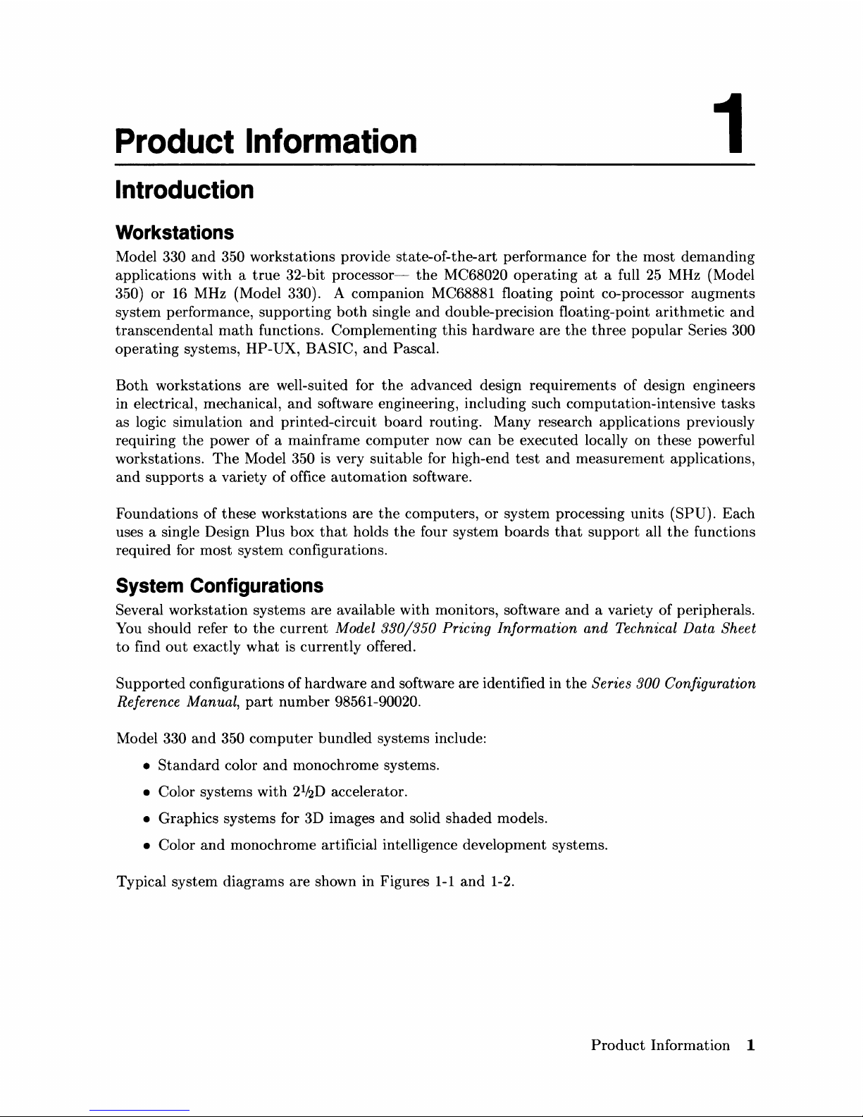
Introduction
Workstations
Model 330
and
350 workstations provide state-of-the-art performance for
the
most
demanding
applications
with a true
32-bit
processor-
the
MC68020
operating
at
a full
25
MHz (Model
350)
or
16
MHz (Model 330). A companion MC68881 floating point co-processor
augments
system performance,
supporting
both
single
and
double-precision floating-point
arithmetic
and
transcendental
math
functions. Complementing
this
hardware
are
the
three
popular
Series 300
operating
systems, HP-UX, BASIC,
and
Pascal.
Both
workstations
are
well-suited for
the
advanced design requirements of design engineers
in electrical, mechanical,
and
software engineering, including such computation-intensive
tasks
as logic simulation
and
printed-circuit
board
routing. Many research applications previously
requiring
the
power
of
a mainframe
computer
now
can
be
executed locally on
these
powerful
workstations.
The
Model 350
is
very suitable for high-end
test
and
measurement
applications,
and
supports
a variety of office
automation
software.
Foundations of these workstations
are
the
computers,
or
system processing
units
(SPU). Each
uses a single Design
Plus
box
that
holds
the
four system
boards
that
support
all
the
functions
required for most system configurations.
System
Configurations
Several workstation systems
are
available
with
monitors, software
and
a variety of peripherals.
You should refer
to
the
current
Model
330/350
Pricing Information and Technical Data Sheet
to
find
out
exactly
what
is
currently
offered.
Supported
configurations
of
hardware
and
software
are
identified in
the
Series 300 Configuration
Reference Manual,
part
number
98561-90020.
Model 330
and
350
computer
bundled
systems include:
•
Standard
color
and
monochrome systems.
• Color systems
with
21i2D
accelerator.
• Graphics systems for 3D images
and
solid shaded models.
• Color
and
monochrome artificial intelligence development systems.
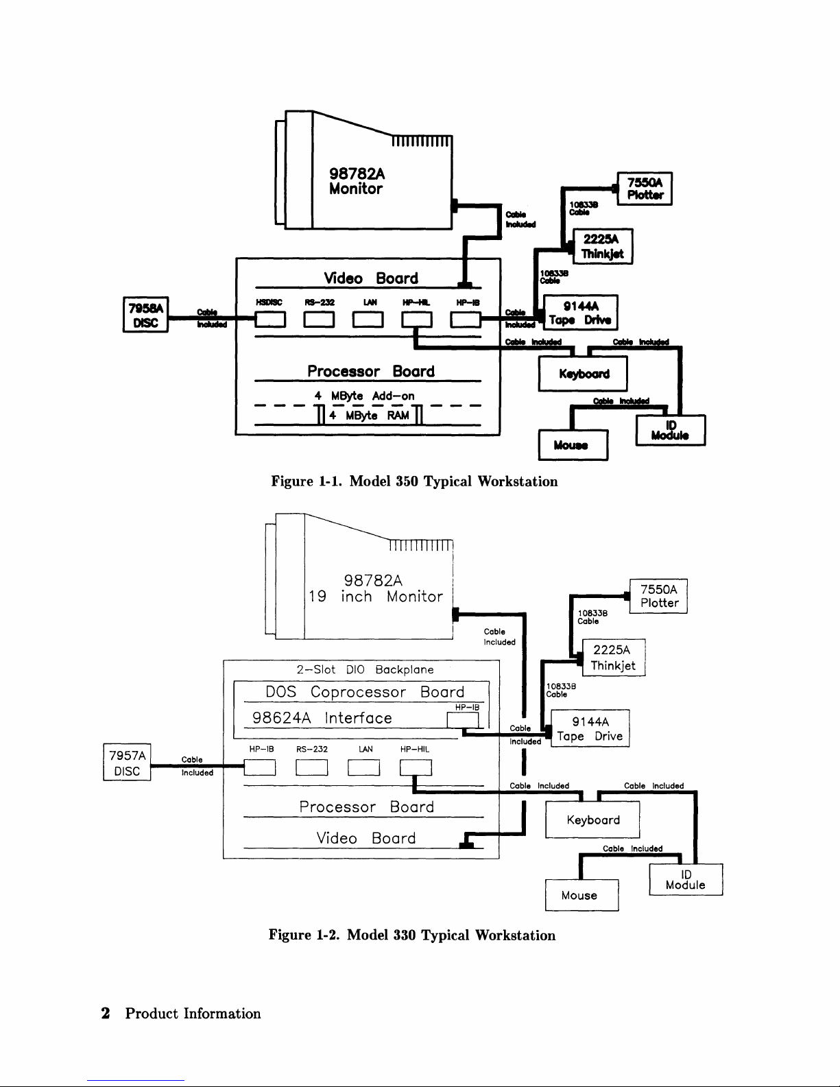
Typical system diagrams
are
shown in Figures
1-1
and
1-2.
Product
Information 1
98782A
Monitor
Video
Boord
DO
Processor
4
MByte
]4MByt;-RA'M] ---
Figure 1-1. Model 350 Typical Workstation
98782A
19
inch
2-Slot
DOS
010
Coprocessor
Boord
Add-on
Monitor
Backplane
Board
Cable
Included
108338
Coble
108338
Cable
98624A
--------------L-,~~~=Wl
Cable
Included
HP-18
Figure 1-2. Model 330 Typical Workstation
2
Product
Information
Interface
RS-232
DO
Processor
Video
LAN
Board
HP-HIL
Board
9144A
Tape Drive
Keyboard
Cable Included

Features
These cornputers have several useful features. Table
1-1
lists
the
main features.
Table 1-1. Model 330/350 Computer Features
Product / Option Description
Number
Model 330 (HP 98562A) Model 330 system processing
unit
featuring:
MC68020 CPU, 16.67 MHz
MC68881 Floating Point
Co-CPU, 16.67 MHz
MC68851 Memory Management Unit, 16.67 MHz
4 Mbytes of Processor
On-Board RAM
4 Mbytes RAM Standard, Maximum 8 Mbytes
Model
350 (HP 98562B) Model 350 system processing unit featuring:
MC68020 CPU,
25
MHz
M C68881 Floating Point
Co-CPU,
20
MHz
HP
Custom Memory Management Unit
8 Mbytes RAM Standard, Maximum
32
Mbytes
32-bit High-Speed
System Bus
Common Features 4 Gbytes Virtual Memory address space
32-bit
DIO-II
I/O
Bus
IEEE-488 HP-IB Interface
RS-232C Serial Interface
IEEE
802.3/Ethernet LAN Interface
with ThinMAU
and
"T" Connector
High-speed
IEEE
488 Disc Interface
(optional on Model
330)
Two channel DMA Controller
HP-IB, HP-HIL,
and
RS-232
adapter
cables.
Direct-Connect
I/O
HP
98568A Opt. 132,
Expanders
8
DIO Card Slots
HP
98570A
2 D I 0-II System Board Slots
4 DIO Card Slots
Backplane Upgrades
HP
98242A
4-slot
DIO backplane.
Can
be added
to
98562B or
to
98570A.
HP
98242B
2-slot
DIO backplane.
Can
be added
to
98562B or
to
98570A.
HP
98570A Opt.
004
provides 2 DIO slots
and
3 system slots.
Memory Boards
HP
98258A 4 Mbyte RAM Board
Optional Model 350 Memory:
HP
98258B 4 Mbyte RAM Add-on
HP
98258C
12
Mbyte RAM Add-on
Product
Information 3
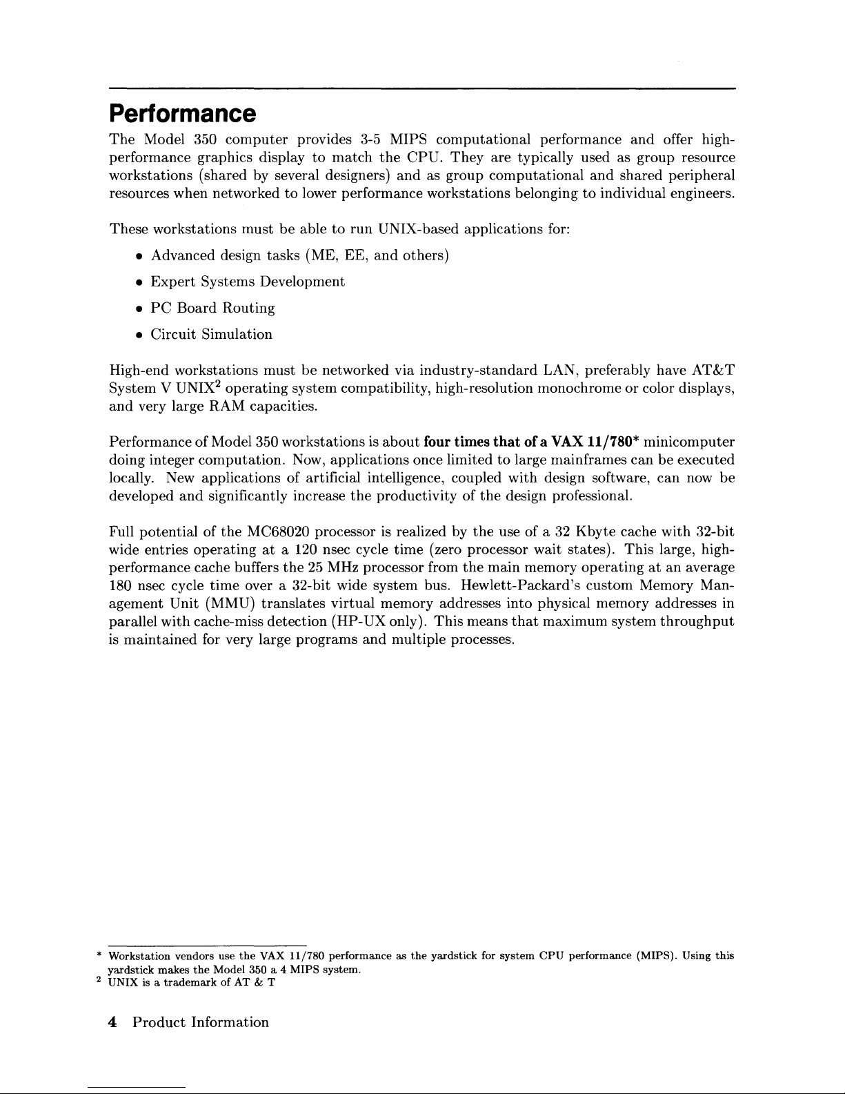
Performance
The
Model 350
computer
provides 3-5
MIPS
computational
performance
and
offer high-
performance graphics display
to
match
the
CPU.
They
are
typically used as group resource
workstations
(shared by several designers)
and
as group
computational
and
shared
peripheral
resources when networked
to
lower performance workstations belonging
to
individual engineers.
These
workstations
must
be
able
to
run
UNIX-based applications for:
• Advanced design
tasks
(ME,
EE,
and
others)
•
Expert
Systems
Development
•
PC
Board
Routing
•
Circuit
Simulation
High-end
workstations
must
be
networked
via
industry-standard
LAN, preferably have
AT&T
System
V UNIX2 operating
system
compatibility, high-resolution monochrome
or
color displays,
and
very large
RAM
capacities.
Performance
of
Model 350
workstations
is
about
four times that
of
a VAX 11/780*
minicomputer
doing integer
computation.
Now, applications once limited
to
large mainframes
can
be
executed
locally. New applications
of
artificial intelligence, coupled
with
design software,
can
now
be
developed
and
significantly increase
the
productivity
of
the
design professional.
Full
potential
of
the
MC68020 processor is realized by
the
use
of
a 32
Kbyte
cache
with
32-bit
wide entries
operating
at
a 120 nsec cycle
time
(zero processor wait
states).
This
large, high-
performance cache buffers
the
25
MHz processor from
the
main
memory
operating
at
an
average
180 nsec cycle
time
over a 32-bit wide system bus.
Hewlett-Packard's
custom
Memory Man-
agement
Unit
(MMU)
translates
virtual
memory addresses into physical memory addresses in
parallel
with
cache-miss detection
(HP-UX
only).
This
means
that
maximum
system
throughput
is
maintained
for very large
programs
and
multiple processes.
*
Workstation
vendors
use
the
VAX
11/780
performance
as
the
yardstick
for
system
CPU
performance
(MIPS).
Using
this
yardstick
makes
the
Model 350 a 4
MIPS
system.
2
UNIX
is a
trademark
of
AT
& T
4
Product
Information
Hardware
CPU
- MC68020
Both
models
are
an
extension
of
the
Series 300 family.
Through
use
of
the
MC68020
at
16
MHZ
(Model
330)
and
25
MHz (Model 350), high-end performance
of
the
Series 300 family
is
almost
doubled
and
provides
state-of-the-art
technology.
Bus
Architecture
A 16-bit
I/O
bus
provides interfacing
to
most Series 200
and
300 accessory cards.
This
bus
is
called
the
DIO bus.
To increase speed, a new 32-bit
I/O
bus
is used in
this
computer
for even higher performance.
This
bus
is called
the
DIO-II
bus
and
provides 6
Mbyte/sec
transfer
rates, handling even
the
highest-performance peripherals independently
of
processor access
to
main memory.
It
is com-
patible
with
the
16-bit DIO
bus
of
the
Series 200
and
the
Model 310
and
320 computers, allowing
access
to
most accessory
and
interface
cards
available for those systems.
Model
350 memory
boards
are
accessed by a
third,
very-high speed :32-bit system bus. Con-
necting between
the
processor
board
and
RAM boards, it allows faster read
and
write
cycles
than
the
I/O
busses would
permit.
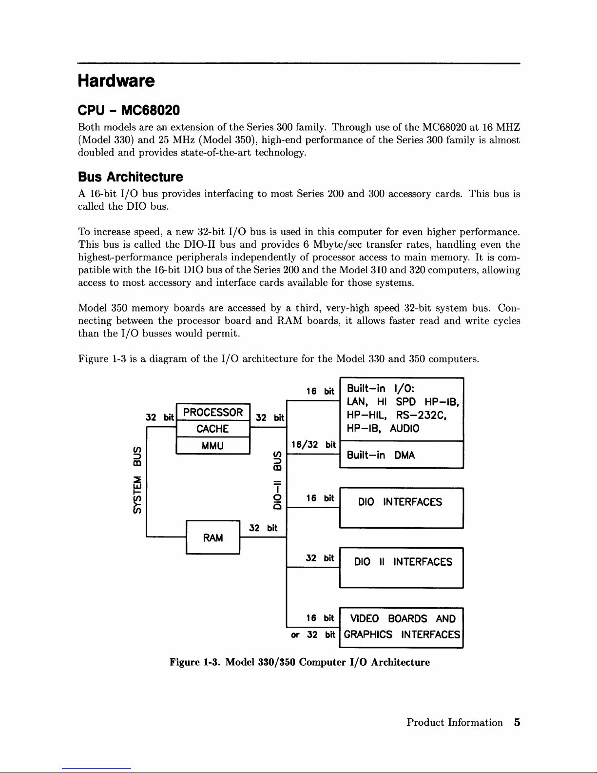
Figure
1-8 is a
diagram
of
the
I/O
architecture
for
the
Model 330
and
350 computers.
16 bit
Built-in
I/O:
LAN.
HI
SPD
HP-IB.
32 bit
PROCESSOR
32 bit
HP-HIL.
RS-232C.
CACHE
HP-IB.
AUDIO
MMU
16/32
bit
(/)
Built-in
DMA
:::::>
m
T
0
16 bit
010
INTERFACES
C
32
bit
RAM
32 bit
010
II
INTERFACES
16 bit
VIDEO
BOARDS
AND
or
32
bit
GRAPHICS
INTERFACES
Figure
1-3. Model 330/350
Computer
I/O
Architecture
Product
Information 5
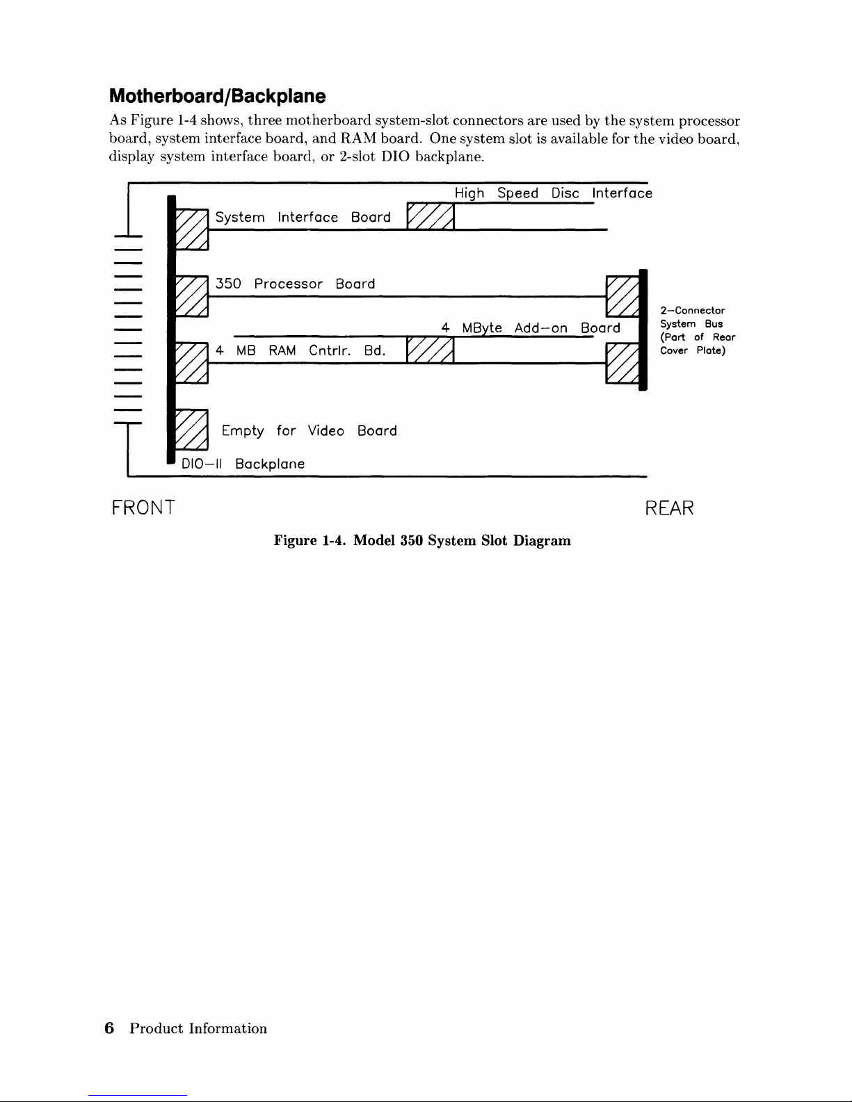
Motherboard/Backplane
As
Figure
1-4 shows,
three
motherboard
system-slot connectors are used by
the
system
processor
board,
system
interface
board,
and
RAM
board.
One
system
slot
is
available for
the
video
board,
display
system
interface
board,
or
2-slot
DIO
backplane.
System
Interface
Board
350
Processor
Board
4
MB
RAM
Cntrlr. Bd.
T
Empty
for
Video Board
010-11
Backplane
FRONT
High Speed Disc
Interface
2-Connector
System Bus
(Port of Rear
Cover Plate)
REAR
Figure
1-4.
Model
350
System
Slot
Diagram
6
Product
Information
Keyboards
Two keyboards
are
compatible
with
the
Model 330
and
350
HP-HIL
interface:
HP
46021A
Standard
keyboard is
the
Integrated
Terminal
Format
(ITF)
Keyboard.
It
connects
to
the
HP-HIL connector on
the
system interface board.
IriP
98203C
An optional keyboard
with
the
same keys
and
rotary
control knob as used
with
several Series
200
and
300
COITlputers.
It
is used on
the
HP-HIL
interface.
HP
9000 Hardware Compatibility
lModel
330
and
350
hardware
compatibility ensures use
and/or
support
of
the
same:
• Series 200/300 interface/accessory
cards
(except 256
Kbyte
and 1 Mbyte
RAM cards).
• Series 300 graphics subsystems
• Peripherals
supported
on
other
Series 300 systems.
These workstations
are
fully compatible
with
the
wide range of disc
and
tape
drives,
printers
and
plotters,
and
HP-HIL devices.
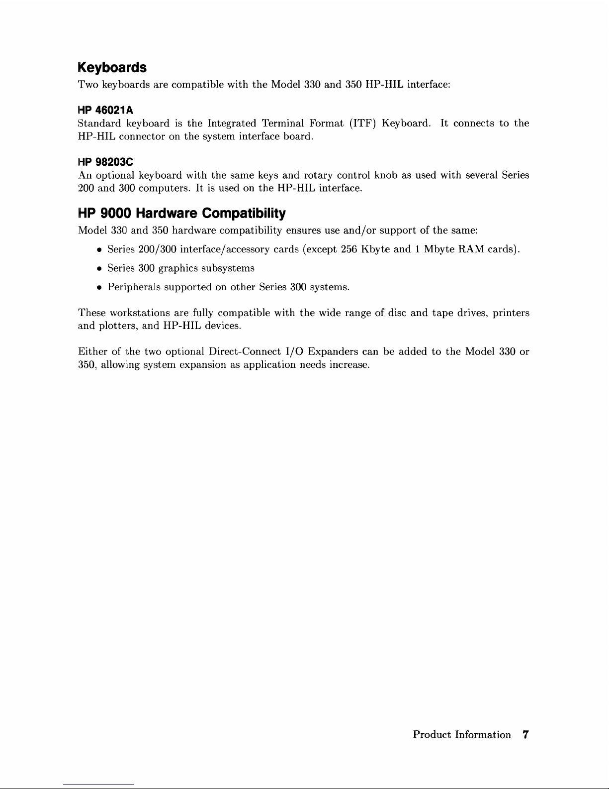
Either
of
the
two optional Direct-Connect
I/O
Expanders
can
be
added
to
the
Model 330
or
:350,
allowing system expansion as application needs increase.
Product
Information 7
FRONT
FRONT
1
1
I
T
98570A
Direct Connect
I/O
Expander
Two
System Slots
350
Four System
Slots
010-11
Backplane
SPU
4-Slot
010
Backplane
Option
004
deletes this
backplane leaving
four
total system slots
REAR
98568A
with
Option
132
1
1
I
T
Direct Connect
I/O
Expander
8-Slot
010
Backplane
REAR
010-11
Backplane
Figure 1-5. Direct Connect
Expanders
Diagram
8
Product
Information
Operating
Systems
HP-UX 5.2
Series 300
HP-UX
5.2
adds
support
for
both
computers
while maintaining object code
compat-
ibility
with
earlier releases.
Programs
will continue
to
run
without
recompiling.
The
5.2 release
supercedes all previous Series
300 releases.
Additional comlnands have been
added
so
that
the
computer
has a command
set identical
to
the
Model 840. All
commands
that
are
not
hardware,
dependent
are
on
the
Series 300 systems,
except
job
control.
The
AppHcation Execution Environment (AXE) is now available in
both
a single-user version
and
a new multi-user version. Single-user limitations have been removed. No additional com-
mands
or
utilities are included.
It
is intended for use
with
run-only multi-user applications.
Additional
administration
may
be
necessary for a multi-user system.
The
multi-user
Program-
ming Environment now requires
the
multi-user
AXE
as a prerequisite.
All
of
these
computer's
HP-UX
systems feature a built-in LAN, allowing
them
to
function as
departmental
resource servers for sharing space on large local discs
and
for sharing
attached
high-quality
printers
and
plotters. Because
the
LAN is
an
industry
standard,
the
Model 350
workstations
can
also be connected
to
other
vendors' systems
to
access
data
and
to
utilize
the
other
computing
resources available
to
the
department.
BASIC 5.0
BASIC 5.0
(HP
98613C) is a revision of
the
Series 200/300 BASIC 4.0, Revision 4.03. BASIC
5.0
provides upward compatibility
with
BASIC
:3.0
and
4.0. New for BASIC 5.0 is a Hierarchical
File Systelm
(HFS) Binary. Model 350 users now have access
to
the
HP-UX
file system directory,
with
or
without
HP-
UX. HFS
is
compatible
with
LIF
and
SRM
and
provides easy switching
between
BASIC
and
HP-UX
via soft re-boot.
BASIC 5.0 is sold
either
as a
standalone
language system
or
bundled
with Series 200/300
systems, including
the
Model 330
or
350.
Pascal 3.2
Pascal 3.2 provides selective file back-up
and
is object code compatible
with
Pascal 3.1. An
HFS Binary also provides access
to
the
HP-UX
file system directory
with
or
without
HP-UX.
Software Compatibility
For software, these computers:
• Use
the
same Series 300 Application Software
Object
Code .
• Are source code compatible
with
HP
Precision Architecture.
Product
Information 9
Product Identification
Several
terms
in
this
manual
are
used
to
describe
and
identify
the
various
parts
of
the
computer
and
bus
expander.
This
section explains
the
terms
used
to
improve your
understanding
of
service information.
Product Identification Terms
Each
product
has
its
set
of
included
hardware
similar
to
that
in Table 1-1.
Product
numbering
conventions used
with
this
cOInputer
are
explained here
to
clarify
the
following information:
• Systems
Ordered
by Customers.
•
Products
Ordered
by
HP
Field Offices.
•
Products
Manufactured
by
HP
Ft.
Collins Systems Division
Systems Ordered
by
Customers.
When
these
computer
systems
are
ordered
by customers, a suffix is
added
to
the
Model
number,
such as Model 350AIM
that
identifies
the
computer
system
ordered by customers. Refer
to
the
Model 350
Hardware
Price
List for a
current
listing
of
all
bundled
systems.
Products Ordered
by
HP
Field Offices.
A five-digit
product
number
is used by
HP
field offices
to
order
the
computers.
This
number
is
strictly
for ordering purposes
and
not
for formal
product
identification.
HP
9000 Series 300
Model 330
and
350
Computer
is
Product
Number
HP
98562A
and
98562B, respectively. A
complete
explanation
of
these
names
and
numbers
is shown
later
in
this
chapter.
Configuration
and
other
product
information is also covered.
Products Manufactured
by
HP
Technical Workstations Operations
At
the
manufacturing
division,
the
computer's
are
built
and
configured using
the
numbering
conventions explained above. Note
that
these
numbers
relate
only
to
the
computer
or
bus
ex-
pander
and
do
not
include peripherals, such as disc drives, some monitors,
and
some accessories.
Other
HP
divisions provide
the
rest
of
the
products
bundled
with
the
computer
system.
Serial Numbers
Serial nurnbers
are
affixed
to
each
computer
and
bus
expander
for identification purposes. A
decal on each
product
has
the
serial number. An example serial
number
is
explained below:
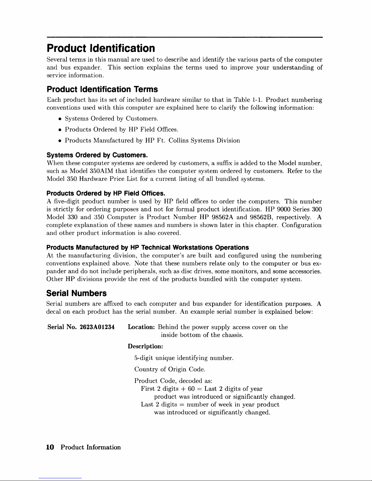
Serial No. 2623A01234
10
Product Information
Location: Behind
the
power supply access cover
on
the
inside
bottom
of
the
chassis.
Description:
5-digit unique identifying number.
Country
of
Origin Code.
Product
Code, decoded as:
First
2 digits + 60 =
Last
2 digits
of
year
product
was
introduced
or
significantly changed.
Last
2 digits =
number
of
week in
year
product
was
introduced
or
significantly changed.
Hardware
Terminology
Hardware
is used
to
define physical elements
of
these
products.
Different
parts
and
locations
of
hardware
items
are
explained below.
Product
Terms/Conventions
The
following
terms
are
used
to
describe
products
and
their
main
parts
and
areas:
•
Computer
- A
product
containing
the
central
processing
unit
(CPU)
and
other
assemblies
such as RAM, interface,
and
video
boards,
and
other
accessory cards. Sometimes
the
computer
is referred
to
as
the
System
Processing
Unit
(SPU).
• DIO Slots -
The
narrow slots for accessories in
the
back
of
the
computer
or
expander.
Two
or
four slots
are
available as
options
for
the
computer
and
expander.
Distinction
between
these
slots are:
•
The
top
slot is
an
accessory
card
slot.
•
The
second slot down is
an
I/O
card
slot.
•
System
Slots -
The
wide slots in
the
computer
or
expander
are
for
the
processor, RAM,
video,
or
system
interface boards.
•
Internal
(circuit) - A circuit, such as
an
interface,
that
is
part
of
the
processor
board.
Internal
does
not
mean
'inside
the
computer's
case
parts'.
•
External
(circuit) - A circuit
that
is
located
on
an
assembly
other
than
the
processor
board.
External
does
not
mean
'outside
the
computer's
case
parts'.
•
Peripheral
- A device
external
to
the
computer,
such as a keyboard, monitor, disc drive,
plotter,
printer,
bus
expander, etc.
•
I/O
:Expander - A device
external
to
the
computer
that
connects
to
the
computer's
DIO-II
bus.
This
device provides power
to
its
installed accessory
cards
and
pernlits
more
of
these
cards
to
be
used in
the
computer
system. Sometimes
they
are
called
bus
extenders. For
the
Model
:350
computer
systems,
the
product
name
is Direct-Connect
System
Slot
I/O
Expander.
•
System -One
or
more
computers
with
one
or
more
peripherals
connected
together
to
run
an
application for a desired
end
result.
PC
Boards
PC
boards
in
the
computer
and
bus
expander
are
made
of
several
component
parts.
Identifying
terms
used in
this
manual
are:
•
Cards -Boards
installed in
the
DIO
card
cage slots.
•
I/O
Card
- A
card
that
outputs
to
and
inputs
from a
peripheral
device.
They
are
installed in
DIO
slots. For example,
an
RS-232
I/O
card.
• Accessory
Card
- A
card
that
only
operates
on
the
DIO
bus
and
does
not
talk.
to
a
peripheral
device.
They
are
installed in
either
I/O
or
accessory
card
slots.
•
Boards
- Assemblies installed in
the
wide
system
slots
or
inside
the
product.
Boards
are
not
usually removed
or
installed by users.
Product
Information
11
Two-board
assemblies
are
those
consisting
of
one
board
connecting
to
the
motherboard
and
an
"add-on"
board
attached
to
the
bottom
board. 8 and
16
Mbyte
two-board assem-
blies
are
examples.
• Backplane -
The
board
in
the
card
cage
with
connectors for
DIO
cards
to
plug into.
Software
Terminology
As used in
this
manual,
software refers
to
information
stored
in,
or
on
a device. Typically,
this
information
can
be
changed
and
can
be
transferred
to
another
location in
the
computer
system.
Types
of
software are:
• Firmware -
The
data
or
instructions
in Read-Only-Memory (ROM) chips.
• Operating
Systems -Computer
languages, such as BASIC, Pascal,
and
HP-UX.
They
have various
commands,
statements,
and
keywords
that
when executed by
the
CPU
in a
particular
sequence, cause
computer
to
manipulate
data
to
some desired
end
result.
• Application Program - A series
of
operating
system
program
lines in a specific sequence
to
cause specific actions, such as accounting, electro-mechanical design,
data
sampling
and
output,
etc.
This
information is sometimes referred
to
as software as it is information
that
is
stored
in
or
on a medium
and
can
be
transferred.
Hardware Support Documentation
The
purpose
of
these
computers
and
expanders
Hardware
Documentation
is
to
support
the
installation
and
maintenance
of
these products.
Hardware
Support
Docu-mentation consists
of
six
manuals
for
the
HP
9000 Series 300 Models 330
and
350
Computers
and
HP
98568A
Opt.
132
and
HP
98570A Expanders:
• Service
Information
Manual
• Service
Handbook
• Service Notes
• Test Tools
Manual
• Self-Paced
Hardware
Training Guide.
•
HP
9000 Series
200/300/500
Site
Preparation
Manual
• Series 300
Computer
Systenl Configuration Reference
The
following
manuals
also relate
to
hardware:
• Various
Installation
Notes
• Series 300
Installation
Reference
• Series 200/300
Peripheral
Installation
Guide
A complete listing
of
titles
and
part
numbers
is
in
Chapter 7 of
this
manual
and
the
Model
330/350
Service
Handbook,
Chapter
10.
12
Product
Information
Service
Information
Manual
This
manual
(the
one you're reading now) contains
tutorial
information on
the
computer's
and
bus
expander's
main features, functional descriptions of each assembly,
and
how
to
replace
these
assemblies.
Its
purpose is
to
serve as a learning tool in
training
environments wherein
the
service person
learns how
the
computer
and
bus
expander
works
and
its
parts
are
replaced. Most of
the
information in
the
Service Information Manual is
not
found in
the
Service Handbook.
Organization of
the
Service Information Manual is as follows:
Chapter
No.
and
Title
Front
Matter
Chapter
1:
Product
Information
Chapter
2:
Assembly Replacement
Chapter
3:
Functional Description
Chapter
4:
Boot
Rorvr Functions
Chapter
5:
Troubleshooting
Chapter
6:
Parts
Lists
Chapter
7:
Reference
Contents
Has legal notices, safety
situations
explained, plus a Ser-
vice Information Locator
to
help you find service infor-
mation.
Introduces
the
computer/bus
expander, covers features,
specifications, options, accessories,
operating
systems,
repair philosophy,
and
a general description of
the
Model
350
Computers
and
HP
98570 Bus Expanders. Has
an
overview of how
the
Hardware
Documentation
is orga-
nized.
In
this
chapter, disassembly
and
reassembly of all field
replaceable
parts
for
the
computer
and
bus
expander
are covered. Reference
to
the
Service
Handbook
and
Chapter
6 is
made
for
part
number
information.
Each assemblies functional description
is
covered
to
block
diagram
level.
The
sequence of events for power-up, self-tests,
and
booting
an
operating
system
are
explained. Turn-on
displays
are
shown.
This
chapter
contains
tutorial
infonnation
for
trou-
bleshooting
the
computer
and
bus
expander. Self-test
errors for
the
computer
and
expander
are
explained.
Has
parts
ordering information, as well as
part
numbers
and
descriptions of field replaceable
parts.
Contains
hardware/software
manual
titles,
and
other
helpful information.
Product
Information
13
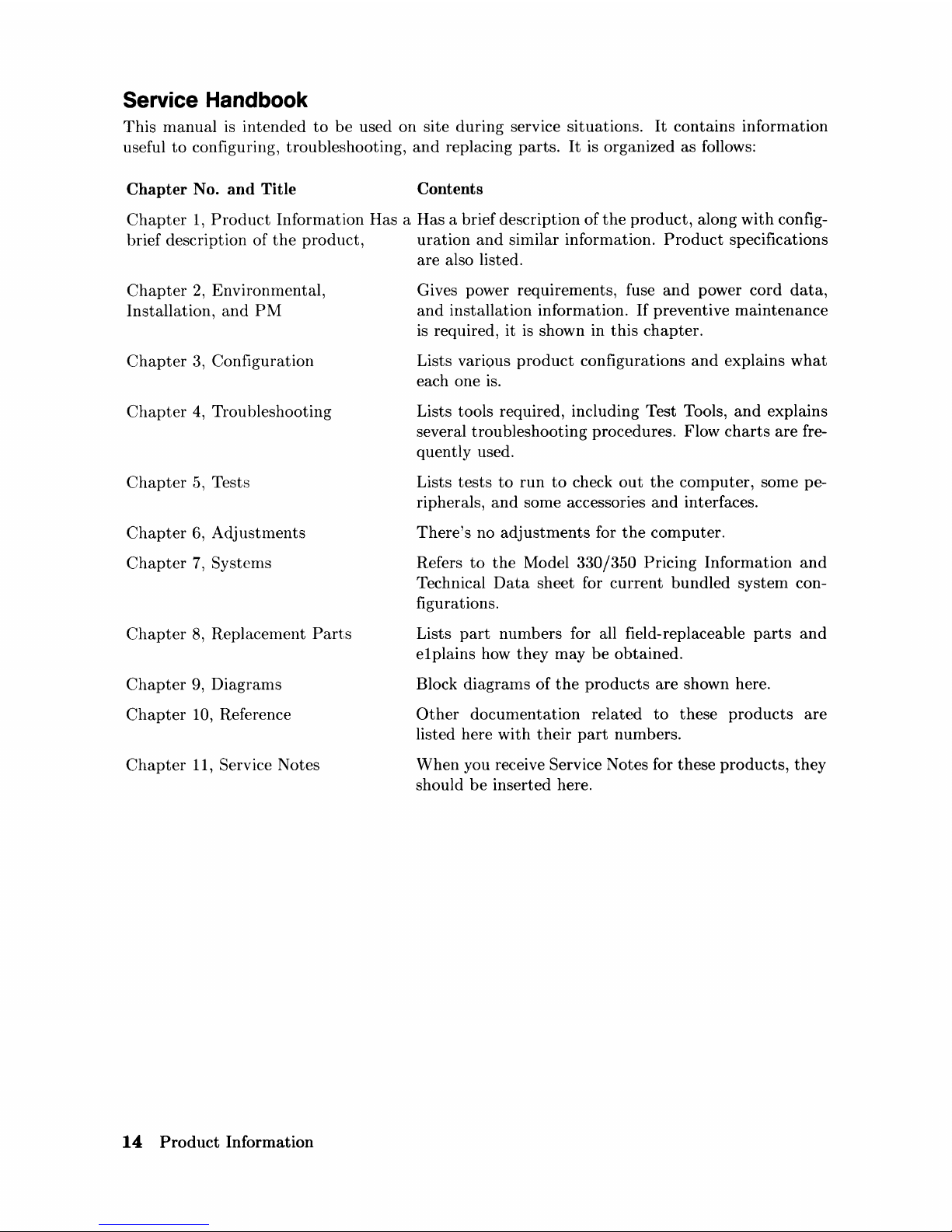
Service Handbook
This
manual
is
intended
to
be
used
on
site
during
service situations.
It
contains information
useful
to
configuring, troubleshooting,
and
replacing
parts.
It is organized as follows:
Chapter No. and Title
Contents
Chapter
1,
Product
Information
Has a Has a brief description
of
the
product,
along
with
config-
brief description
of
the
product,
uration
and
similar information.
Product
specifications
are also listed.
Chapter
2,
Environmental,
Installation,
and
PM
Chapter
3, Configuration
Chapter
4,
Troubleshooting
Chapter
5,
Tests
Chapter
6,
Adjustments
Chapter
7,
Systems
Chapter
8,
Replacement
Parts
Chapter
9, Diagrams
Chapter
10, Reference
Chapter
11, Service Notes
14
Product
Information
Gives power requirements, fuse
and
power cord
data,
and
installation information.
If
preventive
maintenance
is required, it
is
shown in
this
chapter.
Lists various
product
configurations
and
explains
what
each one is.
Lists tools required, including Test Tools,
and
explains
several
troubleshooting
procedures. Flow
charts
are
fre-
quently used.
Lists
tests
to
run
to
check
out
the
computer,
some pe-
ripherals,
and
some accessories
and
interfaces.
There's
no
adjustments
for
the
computer.
Refers
to
the
Model 330/350 Pricing
Information
and
Technical
Data
sheet for
current
bundled
system
con-
figurations.
Lists
part
numbers
for all field-replaceable
parts
and
e1
plains how
they
may
be
obtained.
Block
diagrams
of
the
products
are
shown here.
Other
documentation
related
to
these
products
are
listed here
with
their
part
numbers.
When
you receive Service Notes for these
products,
they
should
be
inserted
here.
 Loading...