

HP 9000 300, 9000 350, 9000 330, 9000 320, 9000 318 Installation Reference
...
Installation Reference
HP 9000 Series 300 Computers
HP
Part
umber
98561-90000
Fliiil
~~
Hewlett-Packard Company
3404 East Harmony Road. Fort Collins. Colorado 80525
HEWLETT
PACKARD
NOTICE
The information containedinthis
HEWLETT-PACKARD MAKESNOWARRANTY OF ANY KIND WITH REGARD TO THIS MANUAL. INCLUDING. BUT NOT LIMITED TO.
THE IMPLIED WARRANTIES OF MERCHANTABILITY AND FITNESS
for errors contained herein or direct. indirect. special. incidental or consequential damagesinconnection with the furnishing. performance.
or
use of
this
material.
documentissubject to change without notice.
FOR
A PARTICULAR PURPOSE Hewlett-Packard shall not be liable
WARRANTY
A
copy
of
the specific warranty terms applicable to your Hewlett-Packard product and replacement parts can be obtained from your local
Sales
and
Service
Office.
CopYright © Hewlett-Packard Company 1986. 1988
This document contains information whichisprotectedbycopyright.
pnor written permission
Use. duplication or disclosure
Rights
In
Technical Data and Software clauseinFAR
is
prohibited. except as allowed under the copyright laws
Restricted Rights Legend
by
the U.S. Government Department of Defenseissubject to restrictionsasset forthinparagraph (b)(3)(ii) of the
52.227-7013.
ii
All
rights are reserved. Reproduction. adaptation. or translation without
Jold--
MANUAL COMMENT CARD
HP
Part
Number 98561-90000 E1188
Your
comments and suggestions help us determine how well we meet your needs.
Installation Reference
Agree Disagree
The manualiswell organized.
Itiseasy·to find informationinthe manual.
The manual explains features well.
The manual contains enough examples.
The examples are appropriate for my needs.
The manual covers enough topics.
Overall, the manual meets my expectations.
You
have used this product:
Less than 1 week
Less than 1 month
Less than 1 year
1 to 2 years
0 0 0 0 0
0 0 0 0 0
0 0 0 0 0
0 0 0 0 0
0 0 0 0 0
0
0
0
0 0 0
0
0
More than 2 years
0
0
Please write additional comments, particularly if
above. Use additional pages if you wish. The more specific your comments, the
more useful they are to us.
Comments: _
Please
Tape
Here
you
disagree with a statement
Please print or type your name and address.
Name: _
Company: _
Address: _
City, State, Zip: _
Telephone: _
Additional Comments: _
Installation Reference
HP Part Number 98561-90000
E1188
BUSINESS REPLY MAIL
FIRST CLASS PERMIT NO. 37 LOVELAND, COLORADO
POSTAGE WILL BE
Hewlett-Packard Company
Attn:
3404
Fort Collins, Colorado
PAID
BY ADDRESSEE
Learning Products Center
East Harmony Road
80525-9988
11111111,,111111,1111.1.1.111,11.11111111111111111,1
NO
POSTAGE
NECESSARY
IF
MAILED
IN
THE
UNITED STATES
Printing History
New editions of this manual will incorporate all material
edition.
additional pagestobe merged into
indicated by a revision
indicates
on a previous page are
The
date
incorporatedatreprintdonot
changes when extensive technical changes are incorporated.
May 1985 Edition 1
May 1986 Edition 2
December 1986
November 1988
Update
the
manual printing
changes when a new editionisprinted. (Minor corrections and
packages may be issued between editions
the
manual by
dateatthe
changes on each page. Note
not
considered revised.
date
and
Edition
Edition
3
4
bottomofthe
part
number
cause
the
that
pages which are rearranged due to changes
indicate its
datetochange.)
the
user. Each
page. A vertical
updated
and
current
The
since
contain replacement
updated
barinthe
edition.
updates
manual
the
previous
page will
margin
The
printing
which are
part
number
and
be
Printing
History
iii

iv
Printing
History
Table of Contents
Chapter1:Installing Your
Introduction.
Getting
How
This
Your
Installing Your
The
The
The
The
Chapter2:Reading the Self-Test
Self-Test Messages
Status
Where to Go Next . . . . . . . . . . . . . . . . . . . . . . . . . . . . . . . . . . . . . . . . . . . . . . .
Error
Boot
Boot
RunninganExtended
What
To Do When
WhereToGet
Boot
ROM
Where to Go Next
Notes
. . . . . . . . . . . . . . . . . . . . . . . . . . . . . . . . . . . . . . . . . . . . . . . . . . . . . . . . ...1
Started.
Reference Is Organized 2
Computer's
Computer
Computer
Monitor Section 8
Keyboard
Video Display Section
Messages
Messages . . . . . . . . . . . . . . . . . . . . . . . . . . . . . . . . . . . . . . . . . . . . . . . . . .
ROM
ROM
Help
Error
System
. . . . . . . . . . . . . . . . . . . . . . . . . . . . . . . . . . . . . . . . . . . . . . . . . . . . . ...1
Parts
Section 5
Section 17
Beeper
Errors
Memory
Errors
Messages
20
24
27
..
27
..
28
28
29
Test
. . . . . . . . . . . . . . . . . . . . . . . . . . . . . . . . . . . .
Occur 30
..
30
31
31
31
32
4
5
Chapter3:Reference
Replacing
Processor Board Switches 35
the
Fuse . . . . . . . . . . . . . . . . . . . . . . . . . . . . . . . . . . . . . . . . . . . . . . . . . . .
Processor Boards for Model 320 37
Processor Boards for Model 330. . . . . . . . . . . . . . . . . . . . . . . . . . . . . . . . . . . .
Processor Boards for Model 350. . . . . . . . . . . . . . . . . . . . . . . . . . . . . . . . . . . . . . 38
Processor Board for Model 318 39
Processor I30ard for Model 319 39
Processor Board for Model 340 40
Processor Boards for Model 360. . . . . . . . . . . . . . . . . . . . . . . . . . . . . . . . . . . .
Processor Boards for Model 370 40
Setting
Processor
Board
Switches 42
Table of
Contents
..
34
..
38
..
40
v
Human
Interface
Human
Card
Interface
Switches
Card
Switches
System Interface Board Switches
HP-IB
and
RS-232 Switches 46
Optional Disc Interface Switches 47
LA
J Switches
Chapter4:Glossary
Chapter5:Installing Add-on Accessories
43
44
45
48
VI
Table of
Contents
Installing
Your
Introduction
This
manual covers
and
keyboards.
For
the
only.
The
purpose of consistency,
term, "the computer" will be used when referringtoany of
the
installation of all Series 300 computers, as well as
Getting Started
Your new
it
setupand
right place.
computer
running,
has
and
System
their
the
computers
just
arrived. You're looking for some easy instructionstoget
you've
turned
will be referredtoby
to this reference for help. You've cometothe
their
product
the
various models.
1
monitors
number
Before you proceed,
computer
reading this reference. You're concerned
finally
you're afraid
schematic of
Forget it.
computer
be
ready to load
documentation. Yes, we know
put
the book down
that
the
That's
system
we
wanttoaddress a
and
actually
we'll presume you have a
computer,
not
together
and
and
tell youtofigure it
goingtohappen
and
turniton.
use your
operating
few
preconceptions you may have
that
you may be less
that
you'll havetoread for hours before you
do
something
Ph.D.
here.
This
When
system or applications program.
with
in electrical engineering, give you a
out
for yourself.
reference tells you howtoput
you're finished
than
enthusiastic
your computer.
with
this manual, you'll
Installing Your
Or
perhaps
System
about
about
can
your
1

How
This
procedures as you
This Reference
reference has two chapters. Please read
go.
Is
Organized
them
in order, performing
the
installation
Chapter
your installation guide
your system.
problems.
Chapter
system
Reference.
tion,
to
Glossary.
Add-on Accessories.
you will install
accessories which you purchase
1 - Installing Your System.
It
expands on
2 - Reading
and
read and
This
but
that
may be valuableata
this section from
This
The
interpret
section contains information
the
section contains definitions of terms used in
If
them
yourself. Store
is
organized.
the
Self-Test.
main
you purchase add-on accessories after your systemisinstalled,
The
The
procedure in
This
the
self-test messages.
later
bodyofthe
the
with
the
system willbeinstalledatthe
section you're now reading tells you how
rest of
chapter tells you howtoturn
date
guide where
installation instructions in this section. Those
the
Installation
that
you
or for
the
chapter
don't
tutorial
appropriate.
explains howtoinstall
Card,
and
deals with any
on your
normally need for installapurposes. You are referred
this
reference.
computer
factory.
2 Installing Your System
'l-
_.-
-
-
....
--,,~-...,.;--~-_
-
....
·~_......-~····
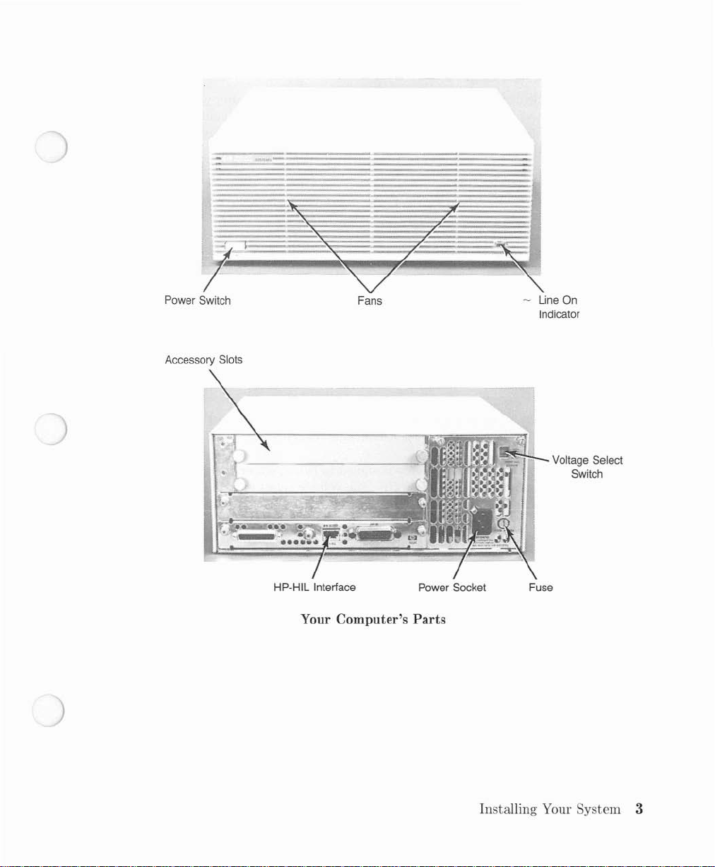
Power Switch
Accessory Slots
Fans
HP-HIL
Interface
Your Computer's Parts
Line On
Indicator
.,
I".~'S'I'+:!-_
Power Socket Fuse
Voltage Select
Switch
Installing Your System 3
Your
Computer's Parts
The
Figures on
tointhis
of
the
however, look
Reference. Note
items
pointed
the
facing page show
out
the
same.
the
various
that
due to
maybein a different place
the
large
partsofthe
number
computer
of different configurations, some
than
in these Figures.
which are referred
They
will,
Power Switch on,
the
switchis"in" or flush
power
be
powered on, switch
is
off.
-LINE
is
Fans -
Accessory Slots - Remove these covers
accessories.
Power Socket cord.
Voltage Select Switch Vac.
to
Fuse - A fuse
ON
off,
the
The
running
The
The
runatthe
HP-HIL Interface - You will plug
Thisisthe
Indicator-This
indicatorisoff.
computer
when
power cordisshipped in
line frequency range is 48-66 Hz.
lower (120 Vac)orupper
ratedat250V, 8A,
has two small built-in fans to keep it cool.
the
the
The
three-pronged power socketisespecially designed for an
switch you usetoturn
with
green indicatorislit when poweristurned
computerison.Ifeither fan ever goes off while
computer
The
off
computerisdesignedtorunateither 85-129 Vac or 187-250
mustbein place for your
your
power on
the
front of
and
to
the
carton
(240 Vac) range.
HP-HIL cable into this receptacle.
the
computer;
call your
install memory cards, interface cards,
The
HP
Service Representative.
this reference came in.
voltage select switch sets
and
the
The
computertorun
off.
When
power
switchis"out" when
on.
When
power
fans should always
the
computer
and
other
HP
power
the
computer
safely.
is
is
4 Installing Your System
Installing
This
section explains how to install your system.Itexpands on
in
the
Installation Picture-guide,
The
computer
guide
due
here except for
Before you move on to
and
familiarize yourself
as you look over
There
are
section,
the
Your
comes in several versions.
to differences in
the
the
four sections to
Keyboard
Computer
the
monitors, which are quite different.
the
first step, lookatthe
wiLh
list.
the
section
and
deals
with
any problems which you may encounter.
Each
version has a different Installation Picture-
hardware. However,
the
computer
installation procedure:
and
the
parts.
Video Display section.
photoatthe
Find
The Computer Section
This
section covers unpacking
Remove the computer from this carton.
The
computerispacked in a large
ahead
and
Go
remove
the
and
computer
installing
carton
from
the
together
the
large box.
computer
withabox
the
procedure presented
the
versions will be covered together
beginning of this
each
part
on your own
the
Computer
mainframe.
section,
containing accessory items.
the
chapter
computer
Monitor
Placeiton
Place
the
computerisdesigned for remote operation. Be sure
inches) of spaceatthe
the
grill in
excessive
the
dust
your desk.
computer
the
front panel
or smoke.
on any convenient surface.
front
and
back for ventilation.
and
out
the
back. Do
It
not
need
not
beatyour work area, as
that
thereisat
The
fans draw cooling air
operate
the
computer
Installing Your System 5
least 50mm
through
in areas
(2
with
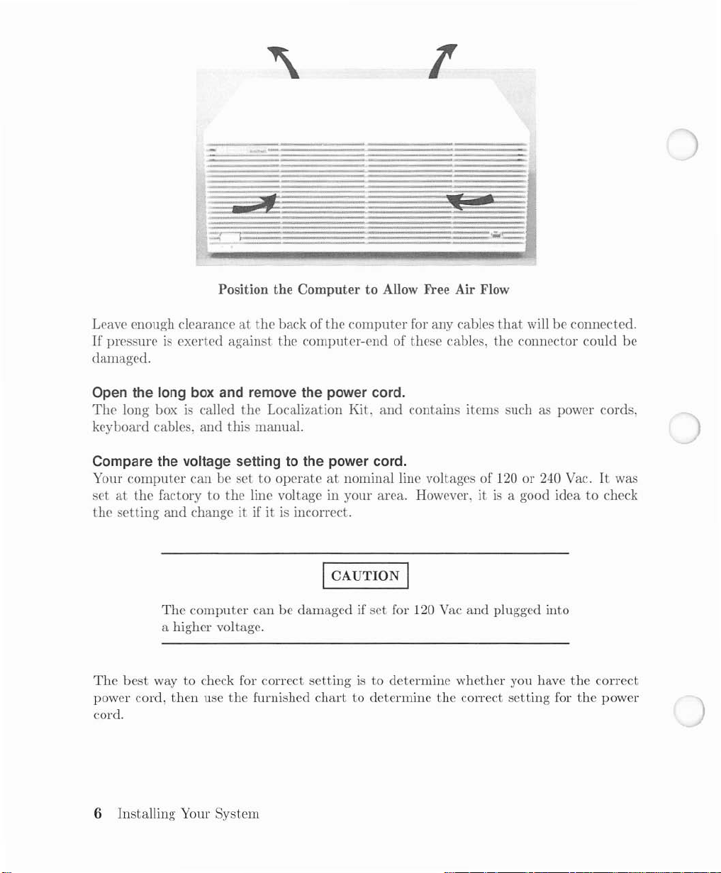
Position the Computer to Allow
Leave enough clearance
If
pressureisexerted against
damaged.
at
the
Free
Air Flow
back of
the
the
computer
computer-end of these cables, the connector could
for any cables
that
will be connected.
be
Open the
The
keyboard cables,
Compare the voltage settingtothe power cord.
Your
set
the
long
box
long boxiscalled
and
computer
at
the
setting
can be set to
factory to
and
change it if itisincorrect.
and remove the power cord.
the
Localization Kit.
this
manual.
operateatnominal line voltages of 120 or 240 Vac.Itwas
the
line voltage in your area. However, itisa good idea to check
and
I CAUTION I
The
The
best
way to check for correct
power cord,
cord.
computer
a higher voltage.
then
use
can be damaged if
the
furnished
set
settingisto
chart
to determine
for 120 Vac
determine whether you have
contains items such as power cords,
and
plugged into
the
correct
the
correct
setting
for
the
power
6 Installing Your System
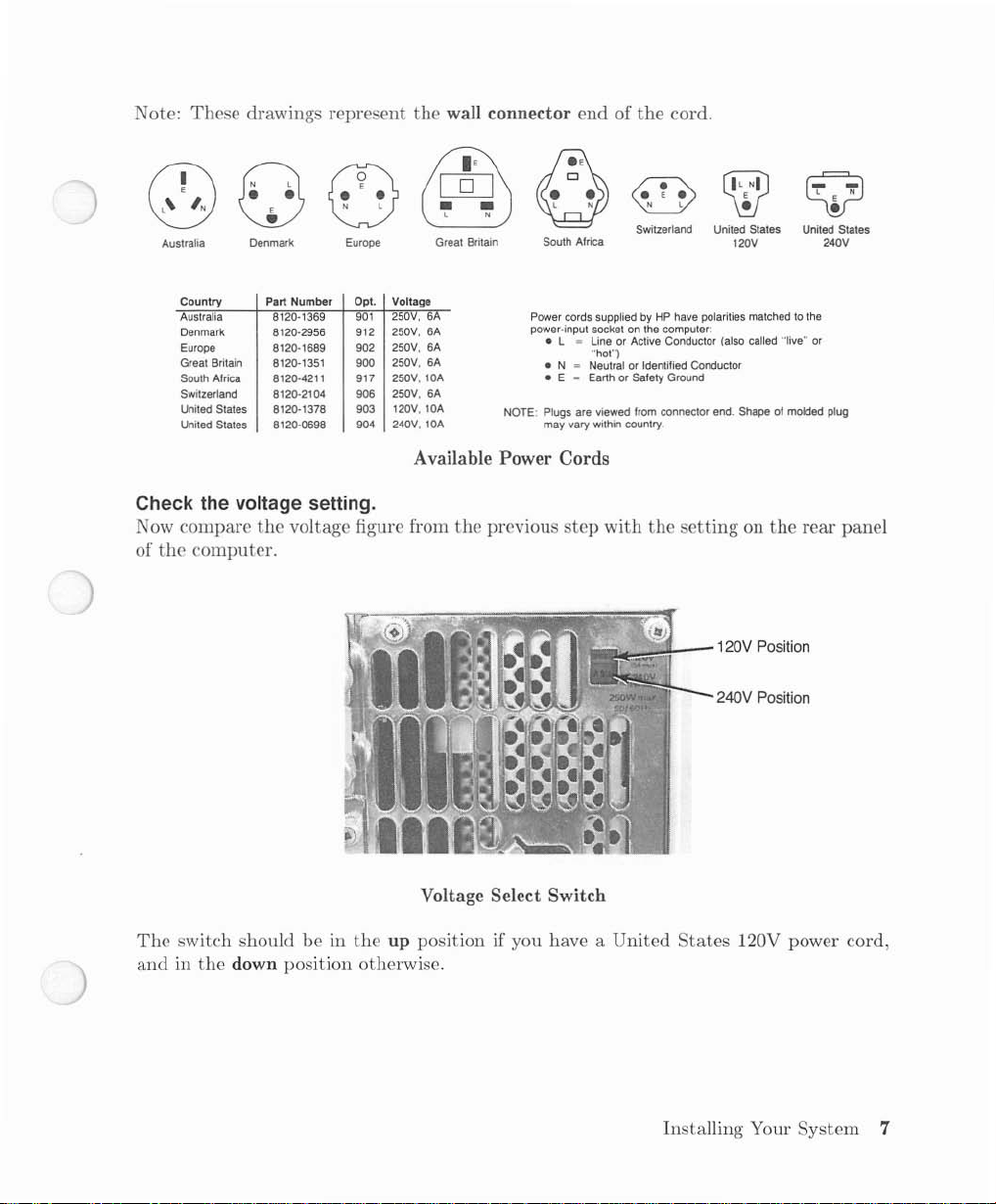
Note: These drawings represent
the
wall connector end of
the
cord.
• •
(3
(0)
Australia
Country Part Number Opt. Voltage
Australia
Denmark
Europe
Great Britain 8120-1351 900
South
Switzerland
United
United
E
•
Denmark
8120·1369
8120·2956
8120-1689 902
Africa
8120·4211
8120·2104 906
States 8120-1378
States 8120-0698
N l
0
Europe
901
912
917 250V, lOA
903
904 240V, lOA
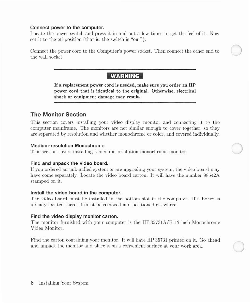
Check the voltage setting.
Now compare
of
the
computer.
the
voltage figure from
[Q]
&§)
• •
l N
Great
Britain
250V, 6
6A
250V,
250V, 6A
250V, 6A
250V, 6A
120V, lOA
• •
0
South Africa
Power
power-input socketonthe
• L
• N
• E
Plugs
NOTE:
may
Available Power Cords
the
previous
l N
cords
suppliedbyHP have
~
LineorActive
"hot")
Neutral
~
EarthorSafety Ground
are viewed
vary
within
step
with
N l
V
Switzerland United States
computer:
or
Identified Conductor
from
connector
country.
the
"':':'Ji-_-120V
CWJ
120V
polarities
Conductor (also
Shape of mOlded plug
end.
settingonthe
240V Position
United States
matchedtothe
"live"
called
rear panel
Position
l N
E
Q
•
240V
or
The
switch shouldbein
andinthe
down position otherwise.
Voltage Select Switch
the
up position if you have a United
States
120V power cord,
Installing Your System 7
Connect powertothe computer.
Locate
set
it to
the
power switch
the
off position
and
(that
press it in
is,
and
the
switchis"out").
outafew
times to get
the
feel of it. Now
Connect
the
the
power cordtothe
wall socket.
If
a replacement power
power cord
Computer's
power socket.
cordisneeded, make
thatisidenticaltothe
Then
sure
you
original. Otherwise, electrical
shock or equipment damage may result.
The Monitor Section
This
section covers installing your video display
computer
are
Medium-resolution Monochrome
This
Find and unpack the video board.
If
you orderedanunbundled system or are upgrading your system,
have come separately. Locate
stamped
Install the video boardinthe computer.
The
already located there, it
mainframe.
separated
by resolution
The
monitors are
and
whether
not
monochrome or color,
section covers installing a medium-resolution monochrome monitor.
the
video
board
on it.
video
board
must
be installed in
must
be removed
the
bottom
and
monitor
similar enough to cover together, so
carton.Itwill have
slot in
the
positioned elsewhere.
connect
order
and
and
the
an
HP
connecting it to
covered individually.
the
video
the
number
computer.Ifa
other
board
end
they
may
9S542A
board
to
the
is
Find the video display monitor carton.
The
monitor
furnished
with
your
computeristhe
Video Monitor.
Find
the
and
carton
unpack
containing your monitor.Itwill have
the
monitor
and
place it on a convenient surfaceatyour work area.
8 Installing Your System
HP
35731A/B 12-inch Monochrome
HP
35731
printed
on it. Go
ahead
ICAUTION I
Turn
your
computer
OFF
before installing
the
monitor.
ICAUTION I
Do
not
obstruct
Check the voltage select settingtobe the same as the computer.
Your monitor has a voltage select switch. Make sure
voltage range as
Find the audio/video cable.
A two-conductor cableisfurnished for audio
at
each end
Connect the audio/video cable.
Connect
Connect
Then
one end of
one end of
connect
and
the
the
otherismarked
the
the
other
the
computer.
the
"Video" cable to
"SPKR"
endstothe
air
ventsatthe
"SPKR".
cabletothe
monitor.
top
and
video. One
the
Video
Audio
and
that
Out
sides of
Out
the
monitor.
the
monitorisset to the
conductorismarked "Video"
connector on
connector on
the
the
computer.
same
computer.
Install the HP-HIL cable.
The
HP-HIL
other.
Locate
Connect
also
coded
Connect
also coded with one dot.
cableiskeyed.Ithas
the
two-dot end of
the
two-dot end of
with
two dots.
the
one-dot end of
the
the
the
HP-HIL
HP-HIL
HP-HIL
a black
cable.Itis
cable to
cabletothe
dotatone end
marked with two black dots.
the
computer.
monitor.
and
The
The
Installing Your System 9
two black
computer
monitor
dotsatthe
socket
receptacle
is
is
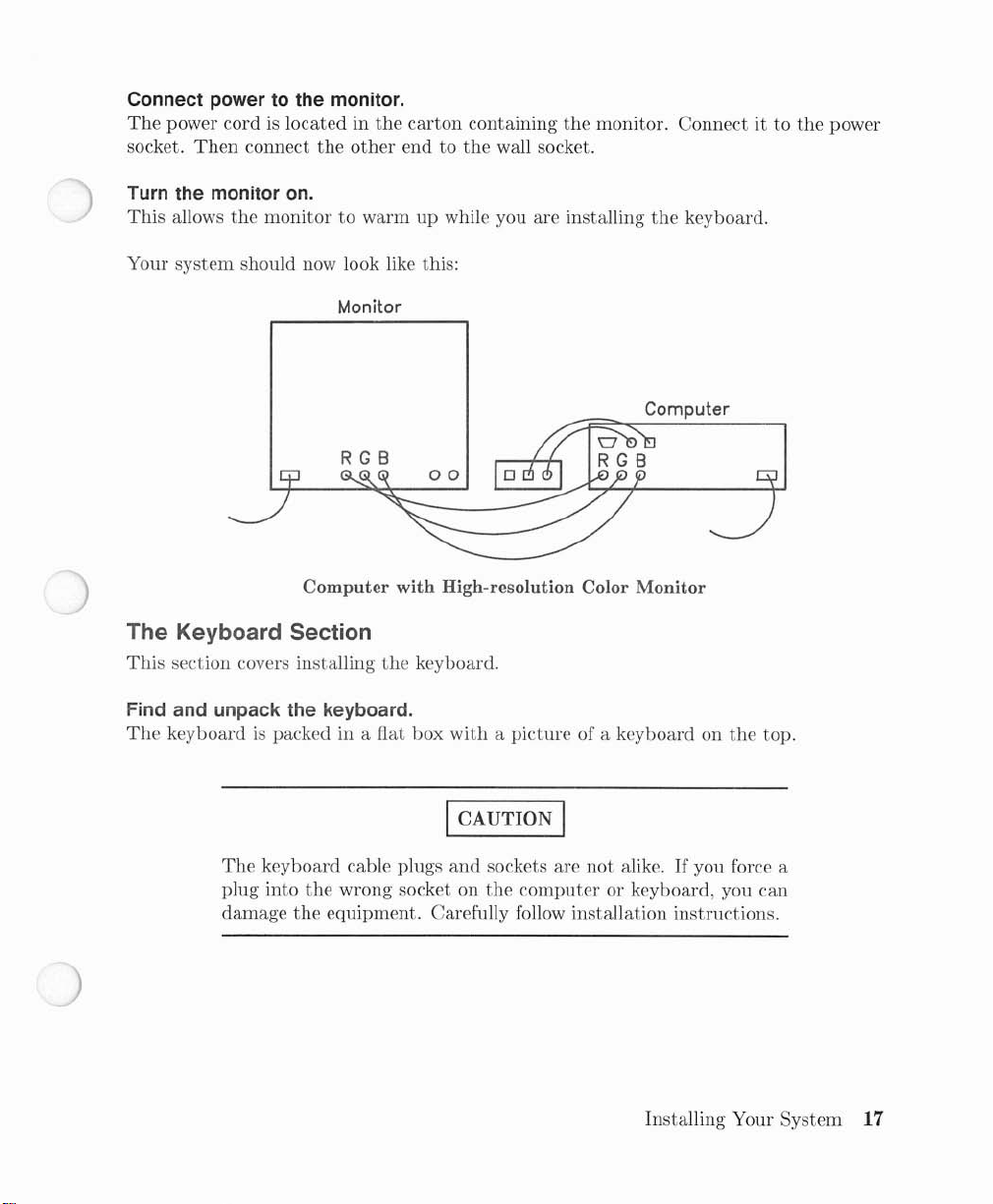
Connect powertothe monitor.
The
power cordislocated in
socket.
Turn
Then
the
monitor01.
connect
the
This
the
other
allows
carton
end to
the
containing
the
wall socket.
monitor
the
to warmupwhile you are installing
keyboard.
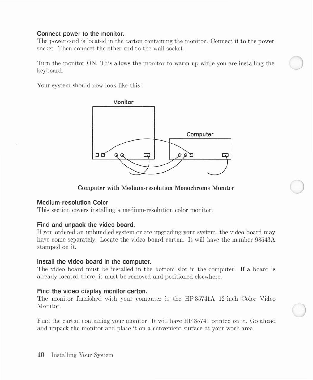
Your system should now look like this:
Monitor
o
Computer with Medium-resolution Monochrome Monitor
Medium-resolution Color
This
section covers installing a medium-resolution color monitor.
monitor. Connectitto
Computer
the
power
the
Find and unpack the video board.
If
you orderedanwlbundled systemorare
have come separately. Locate
stamped
Install the video boardinthe computer.
The
video
on it.
board
must
be installed in
already located there, it
Find the video display monitor carton.
The
monitor
furnished with your
the
video
the
mustberemoved
computerISthe
Monitor.
Find
the
and
carton
unpack
containing your monitor.Itwill have HP 35741
the
monitor
and
place it on a convenient surfaceatyour work area.
10 Installing Your System
upgrading
board
carton.Itwill have
bottom
and
slot in
positioned elsewhere.
your system,
the
the
video
the
number
computer.Ifa
board
98543A
board
may
HP 35741A 12-inch Color Video
printed
on it. Go
ahead
is
Turn
your
computer
Do
not
obstruct
Check the voltage select setting.
Your
monitor
voltage range as
Find the video cables.
The
video cable carries video signals from
has
three
be
used for any color.
Connect the video cables.
The
video cables are color-coded Red, Blue
are labelled R,
connector on
has a voltage select switch. Make sure
the
separate
video cables for red, blue
Band
the
computer.
the
air ventsatthe
computer.
G.
Connect each video cable connectortothe
Then
I CAUTION I
OFF
before installing
I CAUTION I
the
and
and
connect
the
the
top and sides of
that
the
computertothe
green.
The
cables are identical
Green.
other
The
ends of
the
monitor.
the
monitor.
monitorisset to
monitor. Your
monitor
output
appropriate
cablestothe
the
same
monitor
and
may
connectors
video
Monitor.
Install the audio cable.
Now find
between
Install the HP-HIL cable.
The
other.
Locate
Connect
also coded
Connect
also coded
and
the
HP-HIL
the
the
the
install
computer
cableiskeyed.Ithas a black
two-dot
two-dot end of
with
one-dot end of
with
the
and
endofthe
two dots.
one dot.
audio cable.IthasanRCA connector on each end. Install it
the
monitor.
HP-HIL
the
HP-HIL
the
HP-HIL cable
dotatone end
cable.Itis
cable to
to
marked with two black dots.
the
computer.
the
monitor.
and
two black dotsatthe
The
computer
The
monitor
Installing Your System
socket
receptacle
11
is
is
Connect powertothe monitor.
The
power cordislocated in
socket.
Turn
Then
the
connect
monitor
ON.
the
This
the
other
allows
carton
end to
the
containing
the
wall socket.
the
monitor. Connect ittothe power
monitortowarmupwhile you are installing the
keyboard.
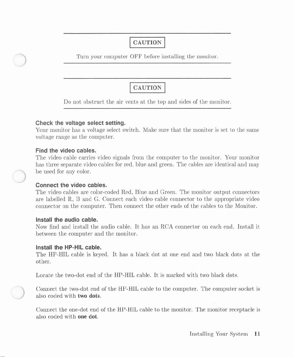
Your system should now look like this:
Monitor
Computer
Computer with Medium-resolution Color Monitor
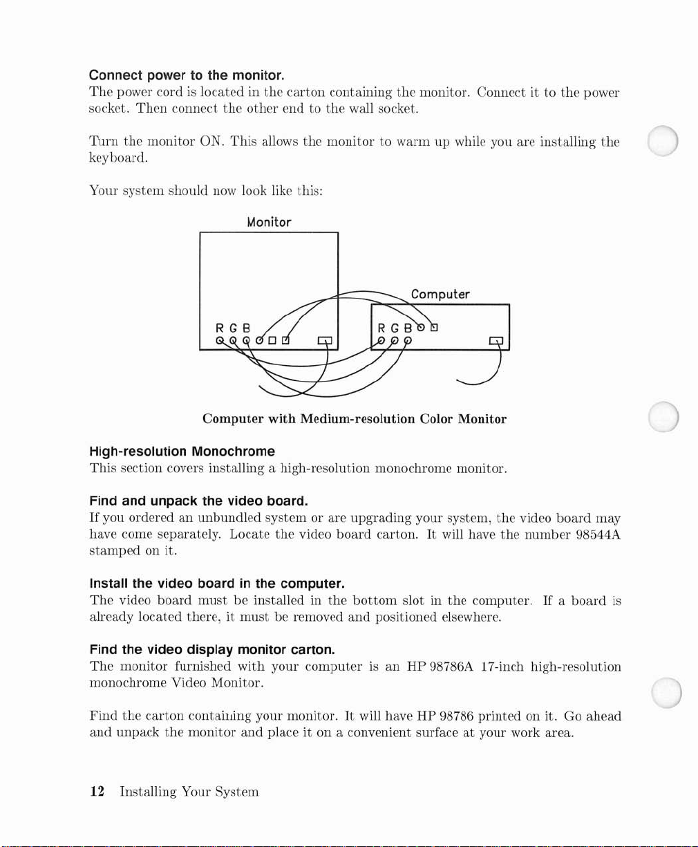
High-resolution Monochrome
This
section covers installing a high-resolution monochrome monitor.
Find and unpack the video board.
If
you orderedanunbundled
have come separately. Locate
stamped
Install the video boardinthe computer.
The
video
on it.
board
mustbeinstalled in
already located there,itmust
Find the video display monitor carton.
The
monitor
furnished
with
system
the
or are
video
be removed
your
computerISan
the
monochrome Video Monitor.
Find
the
and
carton
unpack
contailJing your monitor.Itwill haveHP98786
the
monitor
and
place it on a convenient surfaceatyour work area.
12 Installing Your System
upgrading
board
carton.Itwill have
bottom
and
slot in
positioned elsewhere.
HP
your system,
the
the
video
the
number
computer.Ifa
board
98544A
board
98786A 17-inch high-resolution
printed
on it. Go
may
is
ahead
Turn
your
computer
Do
not
obstruct
Check the voltage select setting.
Your
monitor
voltage range as
Install the video cable.
The
video cableisblack
on
the
other.
has a voltage select switch. Make sure
the
computer.
and
the
air ventsatthe
has an
I CAUTION I
OFF
before installing
ICAUTION I
top
RCA
connector on one end
the
or sides of
that
the
monitor.
the
monitor.
monitorissettothe
and
a BNC connector
same
Connect
the
Install the Speaker Module.
HP
needtoinstall a Speaker Module.
Installation
attaching
The
on a clean,
Suggested locations are
location which interferes
Select a suitable
fastener
attach
the
other
98786A
fastener
pad. Place
the
end
with
the
RCA connectortothe
endtothe
monitor
involves selecting a location for
the
pad
dry
moduletothe
monitor.
does
not
haveaninternal speaker or HP-HIL circuitry, so you will
moduletothe
has a pressure-sensitive adhesive backing.
and
oil-free surface.Itshouldbeflat,
mounting
the
pad.
the
back or side of
with
equipment ventilation grilles.
location
padatthe
fastener pad.
and
remove
location
video
output
the
module, installing a fastener
smooth
the
monitororthe
the
paper
and
press firmly for a
jack on
The
and
edge of a desk. Avoid any
covering from
Installing Your
the
backing
non-porous.
few
computer
must
the
back of
seconds. Now
System
and
pad
be placed
and
the
13
Install the audio cable.
Now find
the
audio cable
and
connect one end to
the
speaker module.
Now locate
Then
Install the HP-HIL cable.
The
the
phono-to-RCA
connect it to
the
RCA
adapter
connector on
HP-HIL cableiskeyed.Ithas
other.
the
Locate
Connect
also coded
Connect
two-dot end of
the
two-dot end of
with
two dots.
the
one-dot end of
module receptacleisalso coded
Connect powertothe monitor.
The
power cordislocated in
socket.
Then
connect the
the
HP-HIL cable.Itis
the
HP-HIL cable to
the
HP-HIL cable to
with
the
carton
other
endtothe
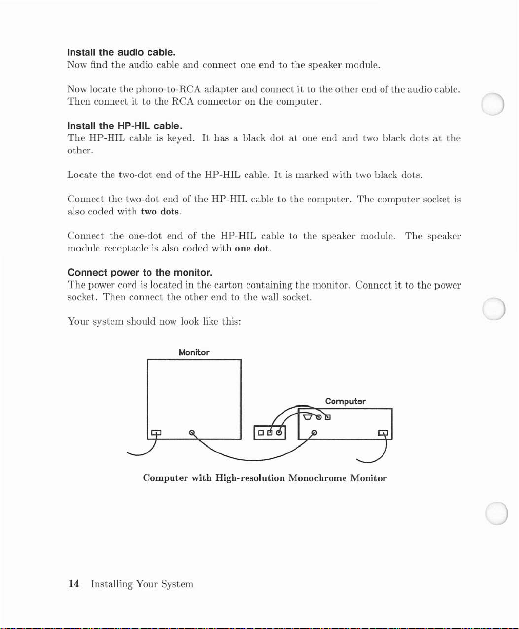
Your system should now look like this:
Monitor
and
the
a black
one dot.
containing
connect it to
computer.
dotatone end
marked with two black dots.
the
computer.
the
the
wall socket.
the
other
end of
the
and
two black
The
computer
speaker module.
The
monitor. Connectitto
audio cable.
dotsatthe
socket
speaker
the
power
is
Computer with High-resolution Monochrome Monitor
14 Installing Your System
Computer

High-resolution Color
This
section covers installing a high-resolution color monitor.
Find and unpack the video board.
If
you orderedanunbundled system or are upgrading your system, the video
have come separately. Locate
stamped
Install the video boardinthe computer.
The
already located there.itmust
Find the video display monitor carton.
The
high-resolution Color Video Monitor.
have
it on a convenient surface
on it.
video
board
must
monitor furnished with your
HP
98751 or
HP
98752
the
video
be installed in
be removed
computerisan
printed
at
your work area.
board
carton.Itwill have the
the
bottom
and
positioned elsewhere.
Find
the
carton
on it. Go ahead
slot in
HP
the
computer.Ifa
98751 or
containing your monitor.Itwill
and
unpack
an
HP 98752A 19-inch
the
ICAUTION I
Turn
your
computer
OFF
before installing
the
monitor.
board
may
number
monitor and place
98547A
board
is
Do
not
obstruct
Check the voltage select setting.
Your monitor
voltage range as
has
a voltage select switch. Make sure
the
computer.
the
air ventsatthe
I CAUTION I
top
and
that
sides of
the
monitor.
the
monitorissettothe
Installing Your System
same
15
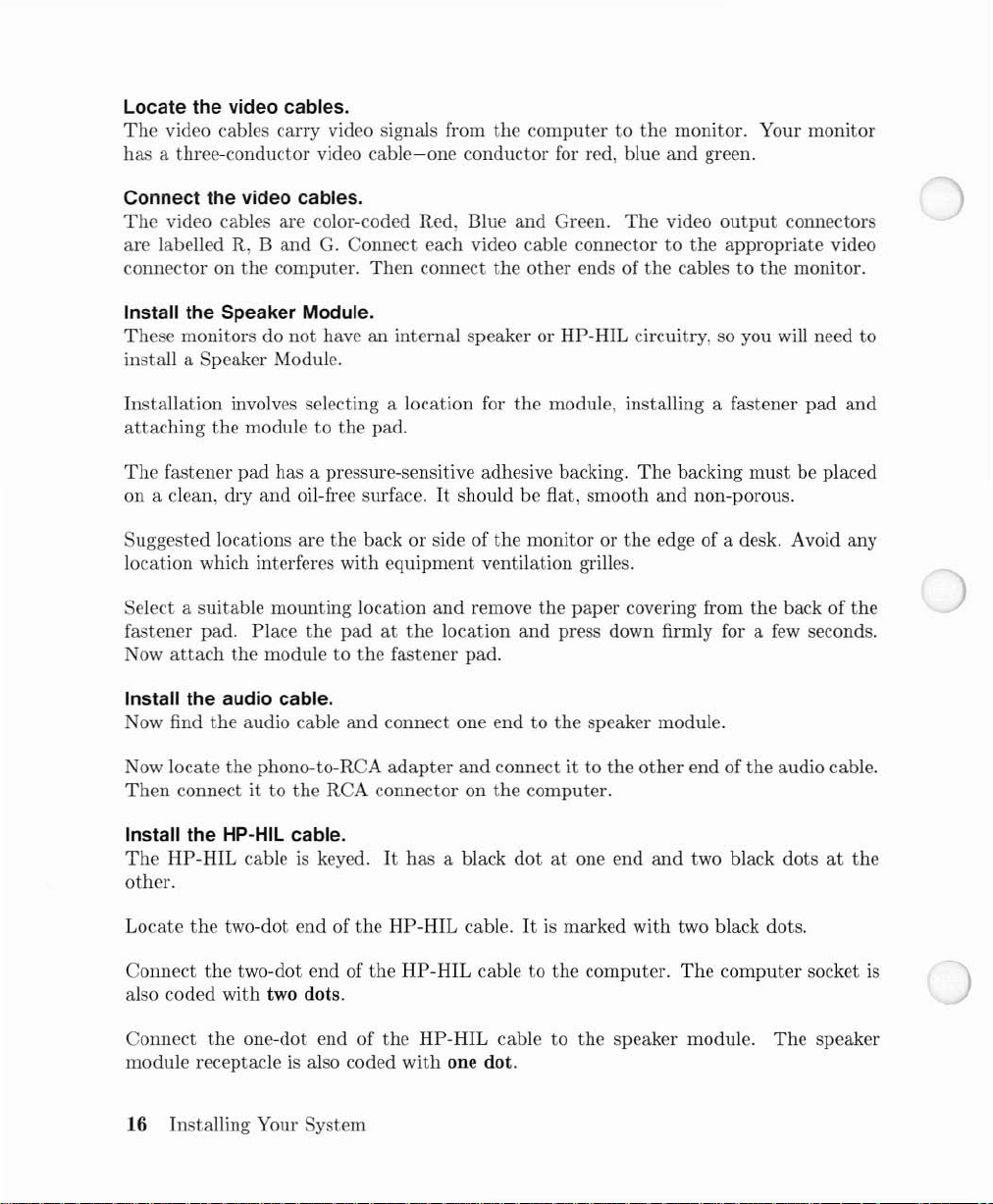
Locate the video cables.
The
video cables carry video signals from
has
a three-conductor video
Connect the video cables.
The
video cables are color-coded Red, Blue and Green.
are
labelled R,
connector on
Install the Speaker Module.
These
monitors do
install a Speaker Module.
Band
the
computer.
not
cable-one
G.
Connect each video cable connector to
Then
connect
haveaninternal speaker or
the
conductor for red, blue and green.
the
computer to
other ends of
HP-HIL
the
monitor. Your monitor
The
video
output
the
appropriate video
the
cables to the monitor.
circuitry, so you will need to
connectors
Installation
attaching
The
fastener pad has a pressure-sensitive adhesive backing.
on a clean, dry
Suggested locations are
location which interferes with equipment ventilation grilles.
Select a suitable mounting location
fastener pad. Place the
ow
attach
N
Install the audio cable.
Now find
Now locate the phono-to-RCA
Then
Install the HP-HIL cable.
The
HP-HIL
other.
Locate
Connect
also coded with two dots.
involves selecting a location for the module, installing a fastener
the
module to
and
the module to
the
audio cable
connectitto the RCA connector on
cableiskeyed.Ithas a black
the
two-dot
the
two-dot end of the
the
pad.
oil-free surface.Itshould be flat, smooth
the
end
back or side of
padatthe
the
fastener pad.
and
connect one
adapter
of the
HP-HIL
HP-HIL
and
the
monitor or
remove
location
and
cable.Itis
cable to the computer.
the
paper
and
press down firmly for a
end
to the speaker module.
connect it to the
the
computer.
dotatone end
marked
The
backing
and
the
edge of a desk. Avoid any
covering from
other
and
with
two black dots.
The
must
non-porous.
the
back of
few
end of
the
audio cable.
two black dotsatthe
computer socket
pad
and
be placed
the
seconds.
is
Connect
module receptacle
the
one-dot end of
is
also coded with one dot.
16 Installing Your System
the
HP-HIL
cable to
the
speaker module.
The
speaker
Connect powertothe monitor.
The
power cordislocated in
socket.
Then
connect
the
the
other
carton
containing
endtothe
the
wall socket.
monitor. Connect ittothe
power
Turn the monitor
This
allows
Your
system
on.
the
monitortowarmupwhile you are installing
should now look like this:
Monitor
RGB
Computer with High-resolution Color Monitor
The Keyboard Section
This
section covers installing
Find and unpack the keyboard.
The
keyboardispacked in a fiat
the
keyboard.
box
with
the
keyboard.
Computer
a picture of a keyboard on
the
top.
The
keyboard cable plugs
plug into
damage
the
wrong socket on
the
equipment. Carefully follow installation instructions.
I CAUTION I
and
sockets are
the
computer
not
alike.Ifyou force a
or keyboard, you can
Installing Your System
17
Locate the keyboard cable.
The
keyboard cableissimilar to
like
the
HP-HIL cable, with
goingtothe
containing
Connect the two-dot endofthe keyboard cable.
Find
the
also has two dots. Install
on
the
Connect the one-dot endofthe keyboard cable.
Install
(as viewed from
Slide
the
up
or down as you like.
speaker module.Itis
the
computer.
two black
dot
speaker module.
the
keyboard cable plug
the
back).
keyboard cable into
end of HP-HIL keyboard cable.
the
the
HP-HIL cable, except
the
one-dot end going to
located in
two
dot
end of
with
one dot in
The
right-hand keyboard socketisalso coded
the
cable
the
the
runonthe
thatitis
the
keyboard
small hox in
The
the
socket on
HP-HIL cable into
the
right-hand socket of
keyboard. Fold
coiled.Itis
and
the
two-dot end
large,
outer
the
speaker module
the
two-dot socket
the
with
the
keyboard
keyed
carton
keyboard
one dot.
stand
18 Installing Your System
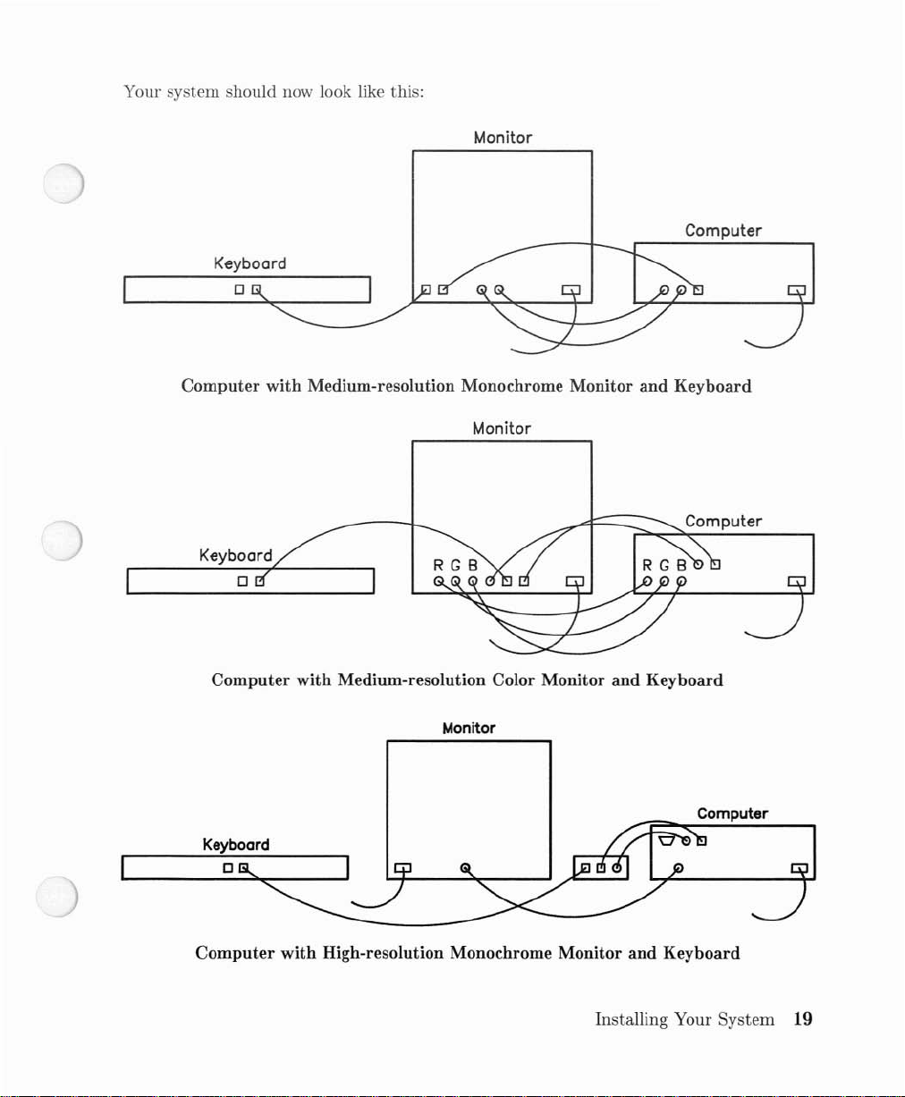
Your system should now look like this:
Keyboard
o
Computer with Medium-resolution Monochrome Monitor and Keyboard
Monitor
Computer
Monitor
Computer
Computer with Medium-resolution Color Monitor and Keyboard
Monitor
Computer
Computer with High-resolution Monochrome Monitor and Keyboard
Installing Your
System
19
Keyboard
o
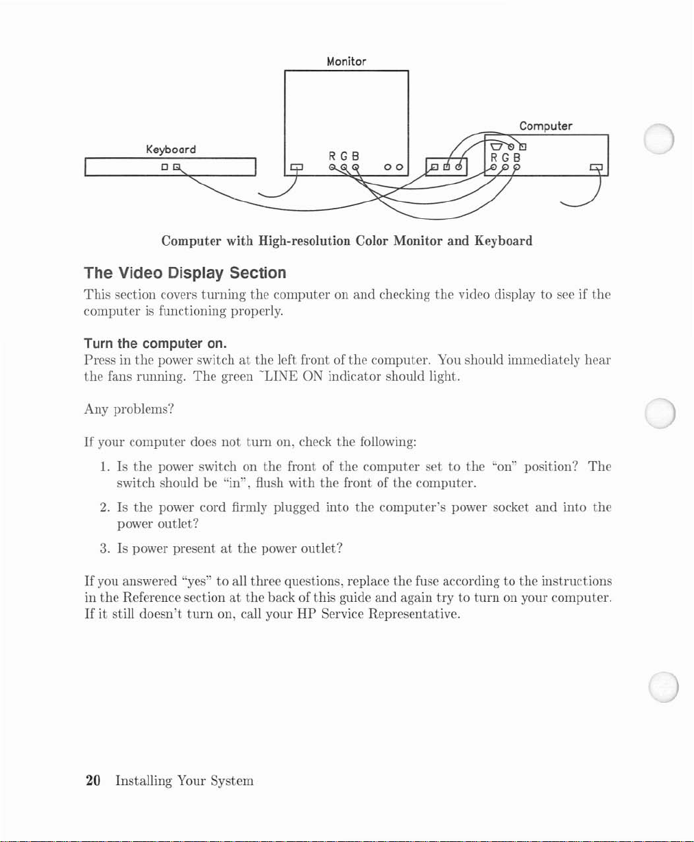
Computer with High-resolution Color Monitor and Keyboard
The Video Display Section
This
section covers
computerisfunctioning properly.
turning
the
computeronand
Monitor
checking
Computer
the
video displaytosee if
the
Turn the computer
Pressinthe
the
fans running.
power switchatthe
The
on.
green
left front of
-LINE
the
ON indicator should light.
Any problems?
If
your
computer
1.
Is
the
switch should be "in", flush
2.Isthe
does
not
turn
power switch on
on, check
the
front of
with
the
the
power cord firmly plugged into
the
front of
power outlet?
3.
Is power presentatthe
If
you answered "yes"toall three questions, replace
in
the
Reference sectionatthe
If
it still
doesn't
turn
on, call your
power
back of
outlet?
this
guide
HP
Service Representative.
computer. You should immediately
following:
computer
the
computer's
and
settothe
the
computer.
power socket
the
fuse according to
again
trytoturn
"on" position?
and
the
on your
hear
The
into
the
instructions
computer.
20
Installing Your System
 Loading...