

Page 1

User Guide
rp5400 Family of Servers
HP Part Number: A5191-96018_ed2
Published: August 2010
Edition: 2
Page 2

© Copyright 2002, 2010
Legal Notices
The information in this document is subject to change without notice.
Hewlett-Packard makes no warranty of any kind with regard to this manual, including, but not limited to, the implied warranties of merchantability and fitness
for a particular purpose. Hewlett-Packard shall not be held liable for errors containedherein ordirect, indirect,special, incidentalor consequential
damages in connection with the furnishing, performance, or use of this material.
Restricted Rights Legend. Use, duplication or disclosure by theU.S. Government is subject to restrictions as set forth insubparagraph (c) (1) (ii)
of the Rights in Technical Data and Computer Software clause at DFARS 252.227-7013 for DOD agencies, and subparagraphs (c) (1) and (c) (2)
of the Commercial Computer Software Restricted Rights clause at FAR 52.227-19 for other agencies.
HEWLETT-PACKARD COMPANY 3000 Hanover Street Palo Alto, California 94304 U.S.A.
Copyright Notices. ©copyright 1983-2002, 2010 Hewlett-Packard Company, all rights reserved.
Windows", WindowsNT",Windows 95", Windows2000", and Windows XP"are registeredtrademarks ofMicrosoft in the U.S. andother countries.
Reproduction, adaptation, ortranslation of this documentwithout prior written permissionis prohibited, except as allowed under thecopyright
laws.
Page 3

Table of Contents
Preface..............................................................................................................................11
Printing History....................................................................................................................................11
What's New?.........................................................................................................................................11
1 Server Overview...........................................................................................................13
2 Server Unpacking and Installation.............................................................................15
Factory Integrated rp54xx Cabinet Installation....................................................................................15
Receive and Unpack A Non-Integrated Server....................................................................................17
Unpacking the server.......................................................................................................................17
Install Deskside Server..........................................................................................................................19
Install Stand-Alone Server in a Cabinet................................................................................................20
Stationary L-Bracket Rail Assembly.....................................................................................................25
Identifying Approved Non-E-Series HP Cabinets..........................................................................25
Identifying E-Series HP Cabinets....................................................................................................25
Identifying Static Rail Kit................................................................................................................26
Installing Stationary Rails................................................................................................................26
3 Installing Additional Components..............................................................................29
Additional Components.......................................................................................................................29
Installing Memory.................................................................................................................................29
Memory Configuration Rules..........................................................................................................29
Installing rp5400 and/or rp5450 DIMMs....................................................................................29
Installing rp5470 DIMMs...........................................................................................................31
Installing Peripheral Component Interconnect (PCI) Cards................................................................32
rp5400/rp5450 PCI Card Slots..........................................................................................................32
rp5470 PCI Card Slots......................................................................................................................33
PCI I/O Card Installation Restrictions.............................................................................................34
PCI I/O Card Installation Order......................................................................................................34
Installing a PCI Card.......................................................................................................................36
Online Addition/Replacement (OLA/R) of PCI I/O cards...............................................................38
Installing Graphics................................................................................................................................38
Graphics Troubleshooting...............................................................................................................42
Installing Disk Drives...........................................................................................................................43
4 Cable Connections......................................................................................................45
Core I/O Connections............................................................................................................................45
Revision A GSP................................................................................................................................45
Revision B GSP................................................................................................................................46
Guardian Service Processor (GSP) Overview.......................................................................................47
GSP LAN.........................................................................................................................................48
GSP RS-232......................................................................................................................................48
GSP Features....................................................................................................................................48
Revision A GSP................................................................................................................................48
Revision B GSP................................................................................................................................49
Configure System Consoles..................................................................................................................49
GSP Cables.......................................................................................................................................50
Configure RS-232 Console...............................................................................................................50
Table of Contents 3
Page 4

HP 700 Series System Console Configuration...........................................................................51
HP700 VT-100 Mode Configuration.....................................................................................51
Configure the Asynchronous Values of the GSP.......................................................................52
Configure Remote Console..............................................................................................................53
Configure the LAN Console............................................................................................................53
Configuring the GSP LAN Port via an ASCII console...............................................................54
Configuring the GSP LAN Port via LAN...................................................................................54
Configure the Web Console.............................................................................................................55
Secure Web Console Installation...........................................................................................................58
GSP Configurable Parameters..............................................................................................................60
Adding Users...................................................................................................................................60
Removing Users...............................................................................................................................61
Return the GSP to Default Configurations......................................................................................62
rp54xx Server Boot Process...................................................................................................................62
Initial Power-up...............................................................................................................................64
5 Utilities...........................................................................................................................67
Configuring the Rev A Guardian Service Processor (GSP)..................................................................67
Configuring the GSP LAN Port.......................................................................................................67
Adding Users...................................................................................................................................67
Removing Users...............................................................................................................................68
Changing the Default GSP Configuration.......................................................................................69
Configuring the Rev B Guardian Service Processor (GSP)...................................................................69
Configuring the GSP LAN Port.......................................................................................................69
Adding Users...................................................................................................................................69
Removing Users...............................................................................................................................70
Changing the Default GSP Configuration.......................................................................................71
6 Troubleshooting............................................................................................................73
Determine Current System State..........................................................................................................73
Troubleshooting and FRU identification..............................................................................................73
Problem Symptoms and Repair Actions.........................................................................................73
Chassis Code to FRU Decode...............................................................................................................75
Cross-Referencing Chassis Log Errors to rp54xx FRUs..................................................................76
Power Supply Failure Example..................................................................................................77
Processor Failure Example.........................................................................................................77
Interpreting System Alerts..............................................................................................................78
Interpreting System Alerts.........................................................................................................78
Sample System Alert..................................................................................................................79
Key FRU Identification Fields for System Alerts.......................................................................79
Interpreting Service Processor Error Chassis Logs.........................................................................79
Accessing Error Chassis Logs....................................................................................................80
Example of Accessing Error Logs..............................................................................................80
Key FRU Identification Fields for Error Chassis Logs...............................................................81
Interpreting Chassis Logs Using the chassis_code.codes File.........................................................81
Run/Attention/Fault LED States...........................................................................................................82
PCI I/O LED States................................................................................................................................89
Expansion I/O LED States.....................................................................................................................91
GSP LED States.....................................................................................................................................93
LAN/SCSI LED States...........................................................................................................................95
Fan, Power Supply, and Disk LED States.............................................................................................96
4 Table of Contents
Page 5

7 Removing and Replacing Components......................................................................97
List of Changeable Parts with Remove and Replace Components ......................................................97
Cardcage Fan...................................................................................................................................97
Core I/O...........................................................................................................................................97
HotSwap Chassis Fan......................................................................................................................97
Disk Drive........................................................................................................................................97
Display Board..................................................................................................................................98
Front Bezel.......................................................................................................................................98
Memory DIMM................................................................................................................................98
PCI I/O Card....................................................................................................................................98
Power Supply...................................................................................................................................99
HotSwap Power Converter Fan.......................................................................................................99
Platform Monitor.............................................................................................................................99
Processor Support Module..............................................................................................................99
Individual Component Remove/Replace Instructions.........................................................................99
Extend the Server out the Front.....................................................................................................100
Insert the Server from the Front ....................................................................................................100
Stand-alone Server Cover Removal...............................................................................................100
Stand-alone Server Cover Replacement........................................................................................101
Top Cover Removal.......................................................................................................................102
Top Cover Replacement.................................................................................................................103
Side Cover Removal.......................................................................................................................104
Side Cover Replacement................................................................................................................104
Front Bezel Removal (Single Piece)...............................................................................................105
Front Bezel Replacement (Single Piece).........................................................................................105
Front Bezel Removal (Two Piece)..................................................................................................106
Front Bezel Replacement (Two Piece)............................................................................................107
Core I/O Removal .........................................................................................................................108
Core I/O Replacement....................................................................................................................108
PCI Card Separator/Extractor Removal.........................................................................................110
PCI Card Separator/Extractor Replacement..................................................................................110
HotPlug Disk Drive Removal........................................................................................................110
HotSwap Software Procedure..................................................................................................111
HotPlug Hardware Procedure.................................................................................................113
HotPlug Disk Drive Replacement.................................................................................................114
Hardware HotPlug Procedure.................................................................................................114
Hot Swap Software Procedure for Attached Physical Volumes..............................................115
Hot Swap Procedure for Unattached Physical Volumes..........................................................116
HotSwap Chassis Fan Cover Removal..........................................................................................117
HotSwap Chassis Fan Cover Replacement ...................................................................................118
HotSwap Chassis Fan Removal.....................................................................................................118
HotSwap Chassis Fan Replacement..............................................................................................118
HotSwap Card Cage Fan Removal................................................................................................119
HotSwap Card Cage Fan Replacement ........................................................................................120
HotSwap Power Supply Removal.................................................................................................120
HotSwap Power Supply Replacement...........................................................................................121
HotSwap Power Converter Fan Removal .....................................................................................121
HotSwap Power Converter Fan Replacement...............................................................................122
Processor Support Module Removal.............................................................................................122
Processor Support Module Replacement......................................................................................123
Memory DIMM Removal..............................................................................................................123
Removing rp5400 Memory DIMMs.........................................................................................123
Removing rp5470 Memory DIMMs.........................................................................................124
Memory DIMM Replacement........................................................................................................124
Table of Contents 5
Page 6

Replacing rp5400 and/or rp5450 Memory DIMMs..................................................................124
Replacing rp5470 Memory DIMMs..........................................................................................125
Display Board Removal.................................................................................................................125
Display Board Replacement..........................................................................................................126
Platform Monitor Removal............................................................................................................127
Removing rp5400 and/or rp5450 Model Platform Monitors....................................................127
Removing The rp5470 Model Platform Monitor......................................................................127
Platform Monitor Replacement.....................................................................................................128
Replacing rp5400 and/or rp5450 Platform Monitors................................................................128
Replacing rp5470 Platform Monitor.........................................................................................129
PCI I/O Card Removal...................................................................................................................129
PCI I/O Card Replacement............................................................................................................130
A Parts and Accessories...............................................................................................133
CRU Physical Location........................................................................................................................133
Customer Replaceable Unit Part Numbers.........................................................................................134
B System Specifications.................................................................................................137
Dimensions..........................................................................................................................................137
Uncrating Space.............................................................................................................................137
Space Requirements.......................................................................................................................137
Computer Room Physical Space Requirements............................................................................137
Server........................................................................................................................................137
Aisle Space................................................................................................................................138
Computer Room Unpacking Space...............................................................................................138
Specify Uncrating Space...........................................................................................................138
Electrical..............................................................................................................................................138
Office High Availability Requirements.........................................................................................139
Server-level Enhanced Power Availability...............................................................................139
Power Protection............................................................................................................................139
Modular PDUs ..............................................................................................................................139
System Power Requirements.........................................................................................................140
LAN and Telephone............................................................................................................................140
Acoustic Safety Standards...................................................................................................................140
Altitude Operation Standards.............................................................................................................141
Effects of Altitude..........................................................................................................................141
Temperature and Humidity Operating Standards.............................................................................141
Thermal Protection Features..........................................................................................................141
C General Site Preparation Guidelines......................................................................143
Electrical Factors.................................................................................................................................143
Computer Room Safety.................................................................................................................143
Fire Protection..........................................................................................................................143
Lighting Requirements for Equipment Servicing....................................................................143
Power Consumption......................................................................................................................144
Electrical Load Requirements (Circuit Breaker Sizing).................................................................144
Power Quality................................................................................................................................144
Sources of Voltage Fluctuations...............................................................................................144
Power System Protection..........................................................................................................144
Distribution Hardware..................................................................................................................145
Wire Selection...........................................................................................................................145
Raceway Systems (electrical conduits) [LAHJ]........................................................................145
Building Distribution...............................................................................................................145
6 Table of Contents
Page 7

Grounding Systems.......................................................................................................................145
Power Distribution Safety Grounding [LAHJ].........................................................................145
Main Building Electrical Ground........................................................................................145
Electrical Conduit Ground..................................................................................................145
Power Panel Ground...........................................................................................................145
Computer Safety Ground....................................................................................................146
Cabinet Performance Grounding (High Frequency Ground)..................................................146
Raised Floor "High Frequency Noise" Grounding...................................................................146
Equipment Grounding Implementation Details......................................................................147
System Installation Guidelines......................................................................................................147
Wiring Connections..................................................................................................................147
Data Communications Cables..................................................................................................148
Environmental Elements ....................................................................................................................148
Computer Room Preparation........................................................................................................148
Cooling Requirements...................................................................................................................148
Basic Air Conditioning Equipment Requirements...................................................................149
Air Conditioning System Guidelines.......................................................................................149
Air Conditioning System Types...............................................................................................149
Basic Air Distribution Systems.................................................................................................149
Air Conditioning System Installation......................................................................................150
Air Conditioning Ducts............................................................................................................150
Humidity Level..............................................................................................................................150
Dust and Pollution Control............................................................................................................150
Metallic Particulate Contamination...............................................................................................151
Electrostatic Discharge (ESD) Prevention......................................................................................152
Static Protection Measures.......................................................................................................152
Acoustics........................................................................................................................................152
Facility Characteristics........................................................................................................................152
Floor Loading.................................................................................................................................152
Raised Floor Loading...............................................................................................................153
Floor Loading Terms................................................................................................................153
Average Floor Loading.............................................................................................................153
Typical Raised Floor Site..........................................................................................................153
Windows........................................................................................................................................154
Space Requirements............................................................................................................................154
Delivery Space Requirements........................................................................................................154
Operational Space Requirements..................................................................................................154
Floor Plan Grid..............................................................................................................................155
Typical Installation Schedule..............................................................................................................155
Site Inspection.....................................................................................................................................155
Delivery Survey...................................................................................................................................157
Index...............................................................................................................................161
Table of Contents 7
Page 8

List of Figures
A-1 Server Rear View.........................................................................................................................133
A-2 Side Service Bay...........................................................................................................................133
A-3 System Board (Access via Top Service Bay)................................................................................134
A-4 Server Front.................................................................................................................................134
C-1 Raised Floor Metal Strip Ground System....................................................................................147
C-2 Delivery Survey (Part 1)..............................................................................................................158
C-3 Delivery Survey (Part 2)..............................................................................................................159
8 List of Figures
Page 9

List of Tables
6-1 Problem Symptoms and Repair Actions.......................................................................................74
6-2 Chassis Log Error to FRU Decoder...............................................................................................76
A-1 Exchange CRUs...........................................................................................................................134
A-2 Non-Exchange CRUs...................................................................................................................135
B-1 Power Requirements....................................................................................................................140
C-1 Effect of Humidity on ESD Charge Levels..................................................................................152
C-2 Floor Loading Term Definitions..................................................................................................153
C-3 Typical Raised Floor Specifications.............................................................................................154
C-4 Customer and Hewlett-Packard Information..............................................................................155
C-5 Site Inspection Checklist..............................................................................................................156
9
Page 10

List of Examples
4-1 CA command.................................................................................................................................52
4-2 LC command.................................................................................................................................54
4-3 LAN Configuration from a PC......................................................................................................55
4-4 GSP Browser Window...................................................................................................................57
4-5 GSP Web Browser Help Screen.....................................................................................................57
4-6 Combined GSP Browser Window.................................................................................................58
6-1 Chassis Log: Reporting Entity Type = System Firmware..............................................................82
10 List of Examples
Page 11

Preface
Printing History
The Printing History below identifies the edition dates of this manual. Updates are made to this
publication onan unscheduled, as needed, basis.The updates will consist of acomplete replacement
manual and pertinent on-line or CD-ROM documentation.
What's New?
The, Upgrade Guide, rp5400 Family of Servers, is new and was developed to provide customers
with system maintenance information for those components called customer replaceable units
(CRUs). Maintenance of CRUs does not require HP customer engineering services, except when
specifically cautioned.The cautions are shown primarily to protect customerproduct warrantees.
November 2002. . . . . . . . . . . . . . . . . . . . . . . . . . . . . . . . . . . . . . . . . . . . . . . . . . . . . . . .First Edition
August 2010. . . . . . . . . . . . . . . . . . . . . . . . . . . . . . . . . . . . . . . . . . . . . . . . . . . . . . . .Second Edition
Printing History 11
Page 12

12
Page 13

1 Server Overview
The rp5400 family of servers are 1-way to 4-way servers based on the PA-RISC processor
architecture. The rp5400 family of servers accommodate up to 16GB of memory and internal
peripherals including disks and DVD ROM/Tape. High availability features include HotSwap
fans and power supplies, and HotPlug internal disk drives. The supported operating system is
HP-UX.
13
Page 14

14
Page 15
2 Server Unpacking and Installation
Factory Integrated rp54xx Cabinet Installation
A factory integrated server is one in which the rp54xx server and associated components are
pre-assembled and shipped from the factory already installed in a Hewlett-Packard E-Series
cabinet. Factory integrated systems reduce the amount of time required to set-up and begin
server operation.
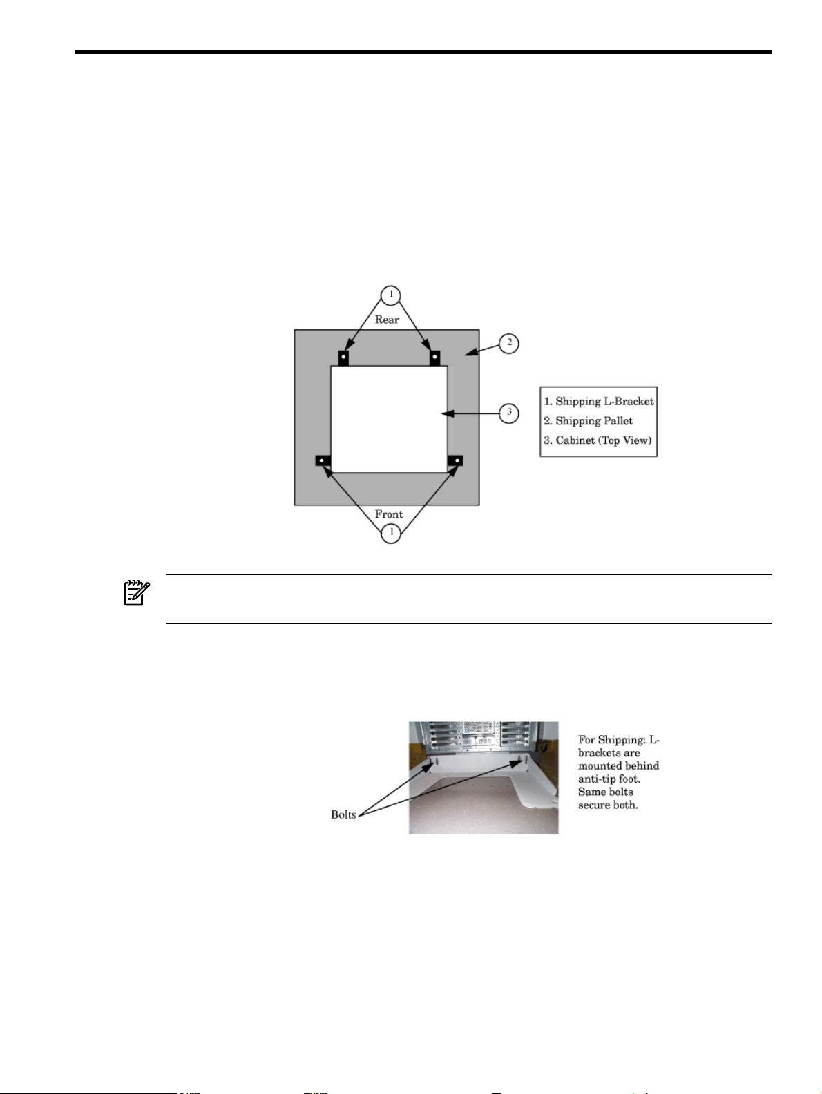
1. Carefully remove the carton and anti-static bag from the pallet.
2. Remove the front two (2) L-brackets. Retain the 1/2-inch bolts for later use.
NOTE: As viewed from the front, one bracket is located on each side at the base of the
cabinet near the front.
3. At the rear of the cabinet:
a. Open the door.
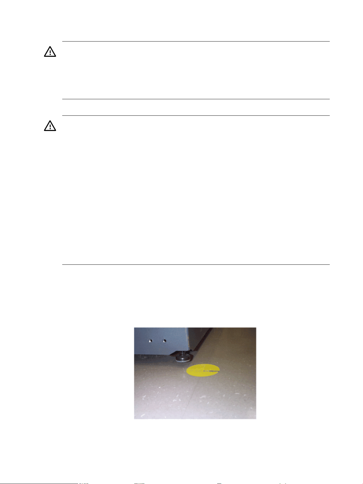
b. Remove the anti-tip foot by removing and retaining the two (2) 1/2-inch bolts.
c. Remove the two (2) L-brackets (revealed by removing the anti-tip foot).
Factory Integrated rp54xx Cabinet Installation 15
Page 16
4. Remove the two ramps from the pallet and carefully place them into the slots at the front
of the pallet.
WARNING! Use extreme care when rolling the racked system down the ramps. A rack
containing one rp54xx can weigh up to 418 lbs. Do not stand in front of the ramps when
rolling the cabinet off the pallet or injury may occur. All but the smallest configurations
require two persons to safely remove the rack from the pallet.
If anti-tip feet or ballast are not installed or are improperly installed the cabinet can tip.
Failure to follow this precaution can cause injury to personnel or damage to equipment.
5. Straighten the rollers on the cabinet base, if needed, and carefully roll it down the ramps.
WARNING! After removing the server from the pallet, Do not move the cabinet unless the anti-tip
feet are installed! The cabinet can tip if care is not used. Due to their low ground clearance
the feet may catch on irregularities on the floor, thresholds, or ramps.
Do not move the cabinet without first installing the anti-tip feet. The cabinet may tip if moved
without the anti-tip feet or ballast installed.
Do not move the cabinet after installing the anti-tip feet unless they are in the fully-raised position.
Once installed, the anti-tip feet must be fully raised to allow ground clearance.
Because oftheir lowground clearance,the fully-raised anti-tip feet may need to be removed
temporarily to clear some obstacles such as door jambs, ramps, and other large irregularities
or obstructions on the floor.
If you must temporarily remove the anti-tip feet to clear an obstacle, use extreme caution
when moving the cabinet. Always reinstall the anti-tip feet as soon as the obstacle has been
cleared.
Lower and secure both the anti-tip feet and the cabinet leveling/stabilizer feet once the
cabinet is in place.
Failure to follow these precautions can result in equipment damage or personal injury.
6. Install the front and rear anti-tip feet using the 1/2 inch bolts provided. Ensure that the
anti-tip feet are installed in the fully up position in the mounting slots. This will provide
maximum ground clearance while moving the cabinet to its final position.
7. Carefully move the cabinet to its installation location.
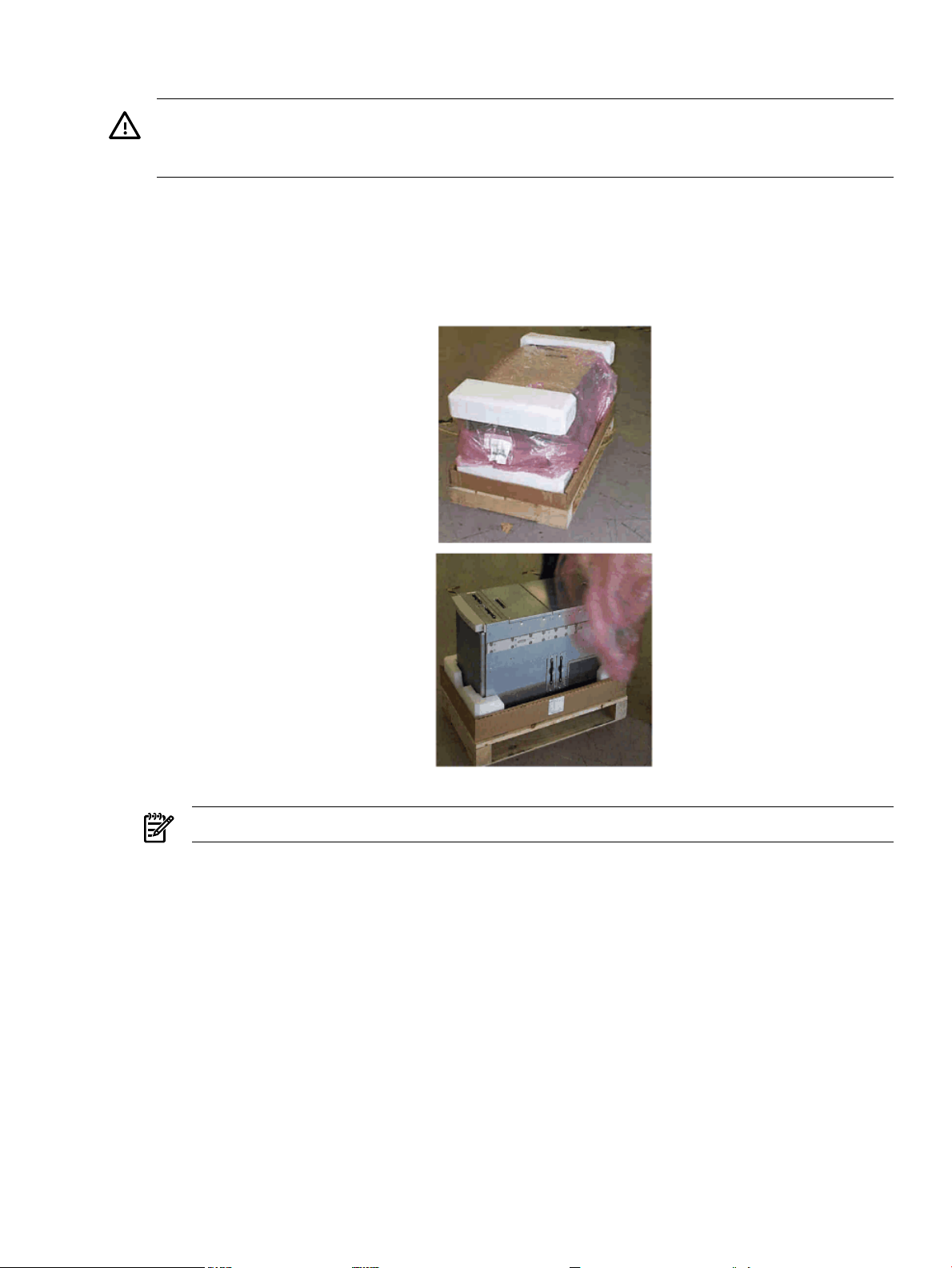
8. Lower the anti-tip feet to the fully down position and adjust the cabinet leveling feetfor best
cabinet stability.
16 Server Unpacking and Installation
Page 17
Receive and Unpack A Non-Integrated Server
WARNING! The typical rp54xx system can weigh up to 68kg (150lbs). HP recommends using an
an approved lifting device. Lift and move the server in accordance with all local safety regulations.
Failure to follow this precaution can cause injury to personnel or damage to equipment.
Unpacking the server
The followingprocedure describes the steps involved in unpackingthe server,whether tofunction
as a stand-alone Deskside unit, or to be integrated into a cabinet.
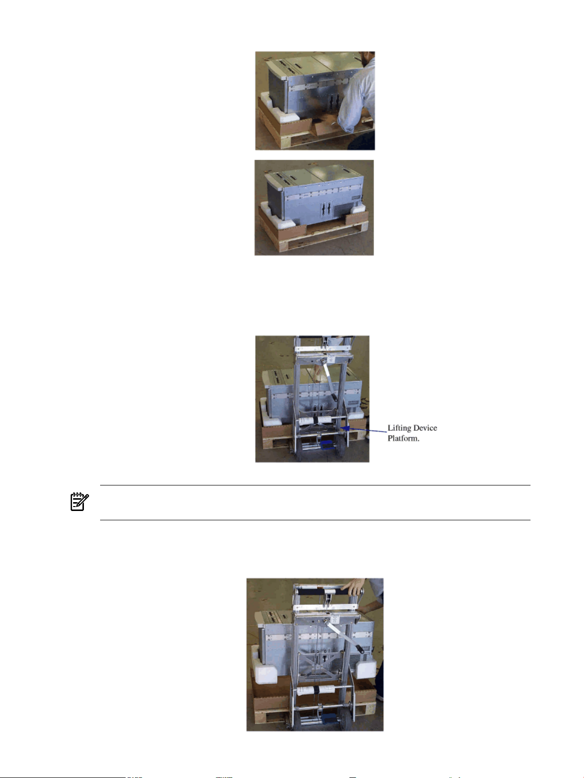
1. Remove the shipping carton and anti-static bag from the server as depicted below.
NOTE: The packaging for rp74xx and rp54xx servers is the same, rp74xx is shown.
2. If you are moving the server manually, use three people to lift the server from the packing
material and pallet. Carefully move the server to the selected location.
3. If you are moving the server by an approved lifting device (such as Genie Lift ™), remove
the tearflap fromthe frontlip ofthe cartonbottom toallow accessto the server, as illustrated
below. Removal of the tear flap will reveal a slot between the bottom of the server and the
inside bottom of the cardboard box.
Receive and Unpack A Non-Integrated Server 17
Page 18
4. Carefully raise the lift's platform so that it will slide into the slot located under the center
of the server, but over the top of the pallet.
NOTE: The server's center of gravity will vary with the hardware configuration, but it is
generally located slightly behind the middle of the server.
5. Raise the lifting device platform enough for the server to clear the pallet and packing
materials, as show below.
18 Server Unpacking and Installation
Page 19
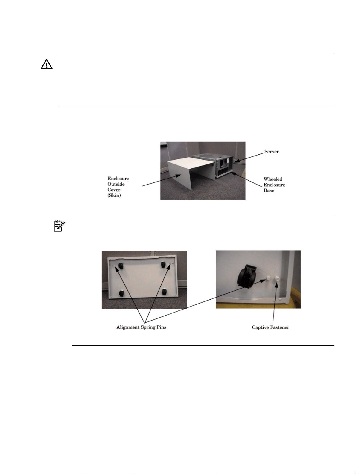
Install Deskside Server
The followingsection describes theinstallation of aserver into a Deskside enclosure forinstallation
in an office environment.
WARNING! The typical rp54xx system can weigh up to 68kg (150lbs). HP recommends using an
approved lifting device.
• Lift and move the server in accordance with all local safety regulations.
• Do not attempt to lift the server by the plastic handles on the top and side covers.
Failure to follow these precautions can cause injury to personnel or damage to equipment.
1. Unpack the server.
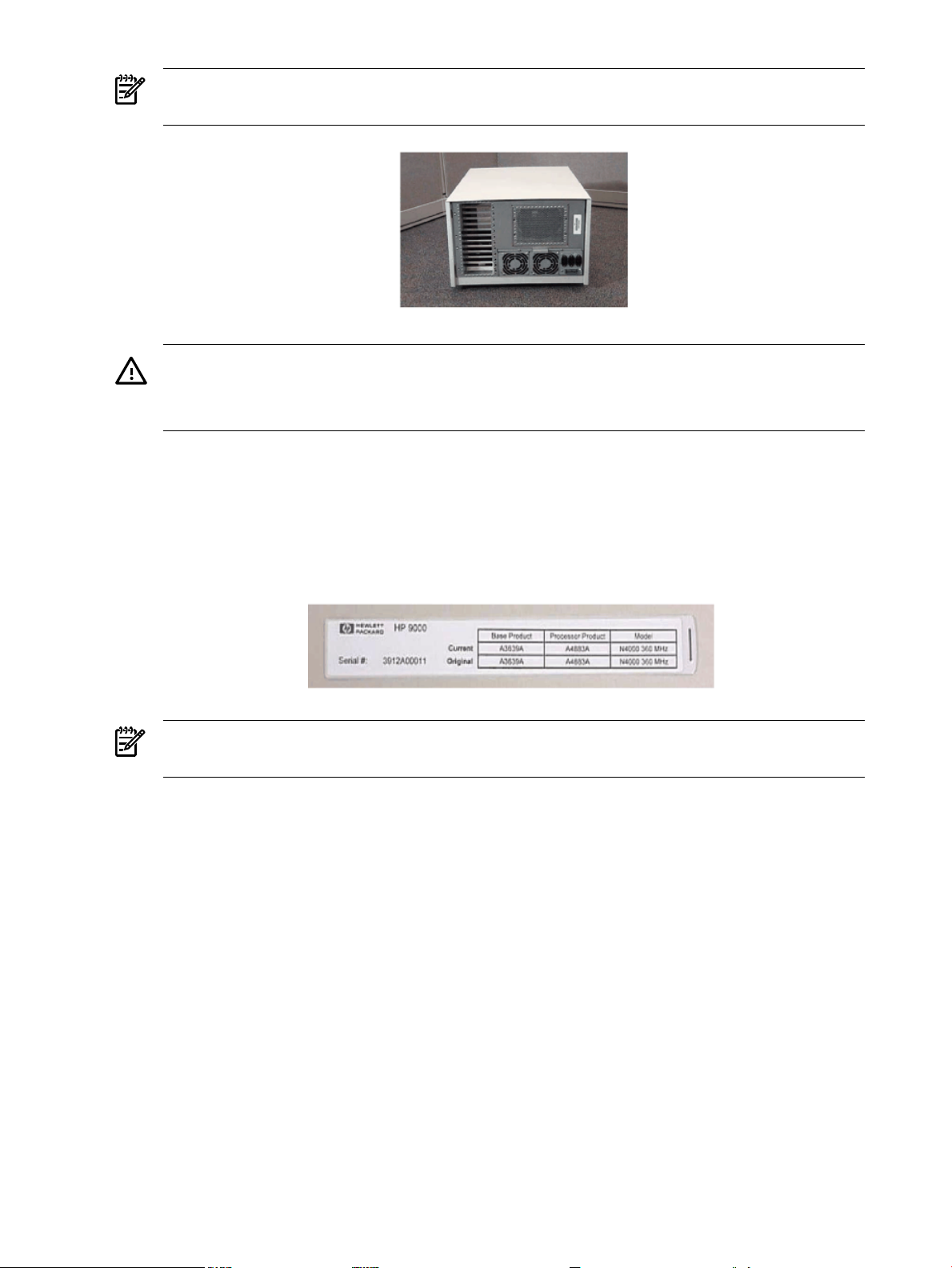
2. Unpack the deskside enclosure.
NOTE: Ensure that the positioning spring pins in the enclosure base align with the
alignment holes in the bottom of the server.
3. Position the server on the wheeled enclosure base.
4. Tighten the two captive screws in the enclosure base to secure the server to the base.
5. Position the enclosure cover (outsideskin) over theserver and install andtighten the screws
to secure it to the base.
Install Deskside Server 19
Page 20
NOTE: The perforations and the lip of the outside skin should be toward the rear of the
server.
WARNING! Stacking rp54xx servers in deskside enclosures is not supported.
Stacking rp54xx servers in deskside enclosures can damage equipment, may cause injury
to personnel, and may void your warranty or service contract.
6. Install the Front Bezel.
7. Locate the two pull-tabs. One pull-tab is longer than the other. The shorter pull-tab is blank
on bothsides. The back of the shorter pull-tab provides a writable surface for Customer use.
8. Locate the plastic bag containing the label sheet (taped to the server).
9. Remove the label containing serial number, base product, processor product, and model
information from the label sheet and apply to the back of the longer pull-tab.
NOTE: Pull-tab and label shown above is for an rp74xx server. rp54xx uses the same style
label and similar pull-tab.
10. Insert the pull-tabs into the front bezel. Install the longer pull-tab in the left side plastic
window in such a way that the rp54xx logo is visible. Install the shorter pull-tab in the right
side plastic window with either surface visible. Refer to the diagram above for pull-tab
locations.
Install Stand-Alone Server in a Cabinet
The following describes how to install the A5556A slide-tray assembly into an approved HP
cabinet in preparation for installing an rp54xx server.
This slide-trayassembly can beinstalled in anHP E-Series cabinetor other HPcabinets approved
for rp54xx system installation. To install the A5556A slide-tray assembly in an approved HP
equipment cabinet, proceed as follows:
20 Server Unpacking and Installation
Page 21
1. Determine what type of cabinet you are installing the slide-tray assembly into.
a. E-Series cabinets have:
• Parchment white, plastic, sectional, side panels
• Black painted vertical frame posts with a partial return flange.
b. Approved, non-E-Series, cabinets have:
• Single piece metal side panels
• Gray painted verticle frame posts with full return flanges.
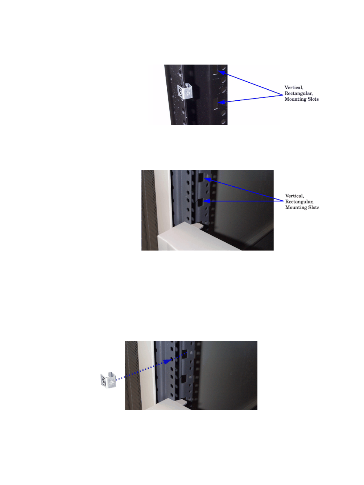
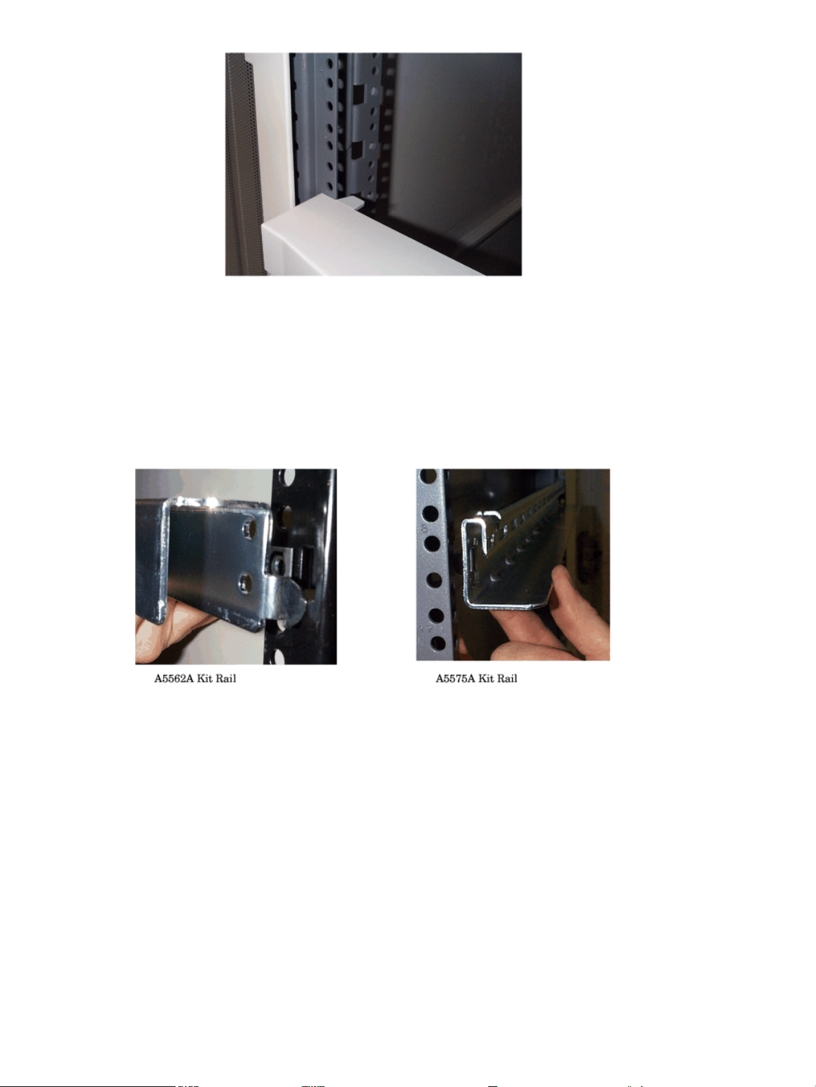
2. Note the vertical, rectangular, slots in the return flanges on the vertical mounting posts.
Determine into which of these vertical slots the slide/tray kit will be installed. This is done
by counting down eight rectangular slots from the top of the cabinet or the bottom of the
equipment above.
3. On the front vertical mounting posts only, slide M5 sheet metal nuts onto the posts over the
holes immediately adjacent to the vertical slots determined in the previous step. Also place
M5 sheet metal nuts on the holes directly above these. Orient the sheet metal nuts so that
the threaded portion faces towards the outside of the cabinet. There should now be a total
of four (4) sheet metal nuts installed.
4. If the cabinet is a non-E-Series cabinet, discard the left hand and right hand aluminum
spacers and two of the M5 x 16 screws with cress-cup washers and proceed to step 12.
5. If the cabinet is an E-Series cabinet, place the hook of the aluminum spacer marked "L"
(5183-1864) into the appropriate vertical, rectangular slot on the front, left hand mounting
Install Stand-Alone Server in a Cabinet 21
Page 22
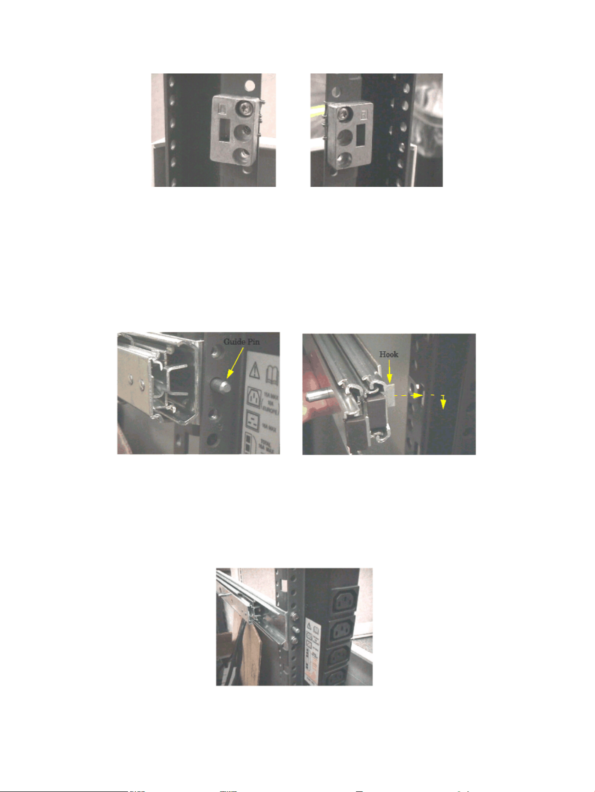
post. The hook points downward. Similarly, place the spacer marked "R" (5183-1863) into
the appropriate slot on the right hand mounting post.
6. Use one M5 x 16 screw with cress-cup washer to attach each spacer to its vertical post. Do
this by inserting the screw through the top hole in the spacer, through the mounting rail
and tightening it into the sheet metal nut located at that position.
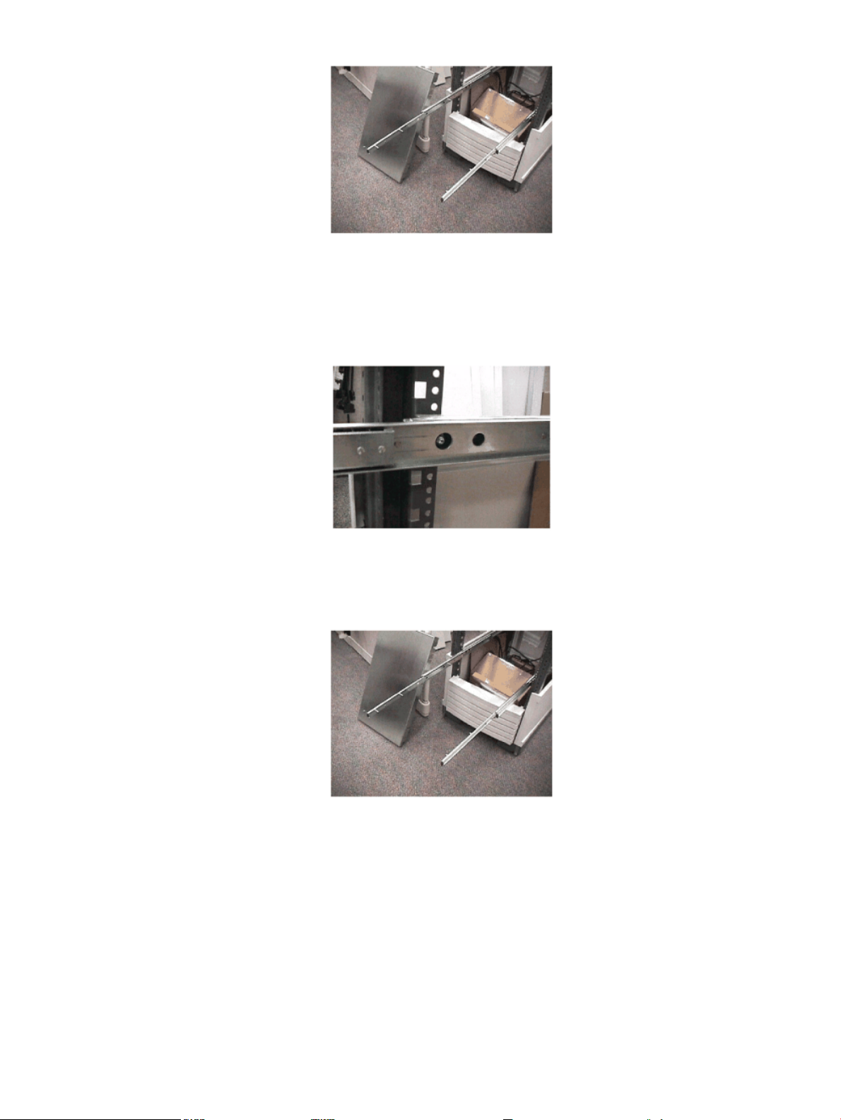
7. Take the lefthand slide/bracket assembly (marked337079-1L) and install it intothe left hand
vertical mounting posts. This is done by inserting the pin at the rear of the slide's mounting
bracket into the 23rd hole in the rear vertical mounting post and inserting the hook at the
front of the bracket into the vertical, rectangular slot in the aluminum spacer. The slide
should be positioned in the cabinet so that it is horizontal and level.
8. Securely fasten the rear of the slide's mounting bracket to the rear vertical mounting post
by installing and tightening two of the M5 x16 screws with cress-cup washers thorough the
mounting post, through the slides mounting bracket and into the threaded nuts attached to
the mounting bracket.
9. Fully extend the slide so that it is locked in the fully open position.
22 Server Unpacking and Installation
Page 23
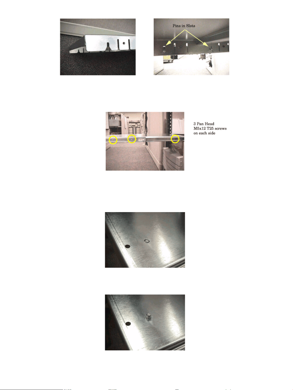
10. Use an M5 x 30 screw with a cress cup washer to attach the front of the slide to the vertical
mounting post. Insert the screw through the slide, through the center hole of the aluminum
spacer, through the vertical mounting post, and tighten into the sheet metal nut located at
that position.
11. Usea procedure similarto steps 7 through 10 to install theright handslide/bracket assembly
(marked 337079-1R) and then proceed to step 12.
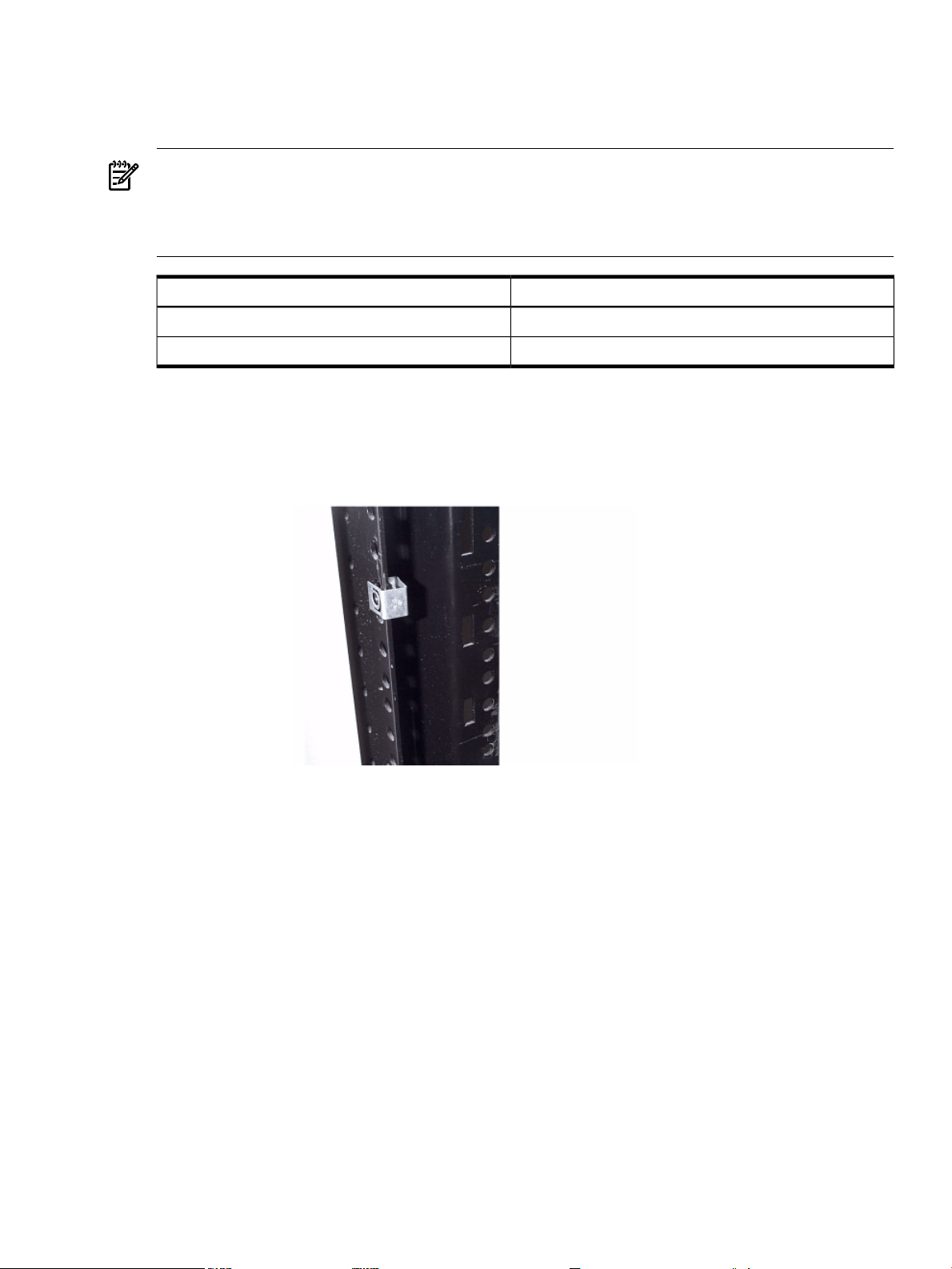
12. Take the trayand place it onto the pins that extend from the slides' inner members. The slots
with wide lead-in guides on the side of the tray fit down onto the slides' pins. The flat part
of the tray will be on top, and the mounting holes in the top of the tray will be located to
the right of the center of the tray. Slide the tray all the way down on both sides so that the
pins reach the top of the slots in the side of the tray.
Install Stand-Alone Server in a Cabinet 23
Page 24
13. Use six, M5 x 12 screws (without washers) to attach the tray to the slides. Three screws are
used to attach each slide. Insert the screws through the slides, through the tray and tighten
into the threaded nuts located on the inside of the sides of the tray.
14. From the bottom of the tray pull the plunger pin down and give it a 1/4 turn to hold it in
place.
15. Position the server on the tray aligning the plunger pins with the alignment holes in the
chassis.
16. Release the plunger pins to secure the server.
24 Server Unpacking and Installation
Page 25
Stationary L-Bracket Rail Assembly
rp54xx servers may be installed intoE-Series andapproved Non- E-Series cabinetsusing stationary
L-bracket rail assembly kits listed below.
NOTE: rp54xx servers are supported in Hewlett-Packard E-series and approved Non- E-series
Hewlett-Packard cabinets, and approved rail kits.
For information on additional qualified 3rd party cabinets and rail kits, contact the nearest
Hewlett-Packard Response Center.
Rail Kit Product NumberCabinet Type
A5575AE-Series HP Cabinet
A5562AOther Approved HP Cabinet
Identifying Approved Non-E-Series HP Cabinets
Approved Non- E-Series cabinets haveblack frames, onepiece outside sheet metal skins, a partial
return flange, and requires the installation of the aluminum spacer blocks, supplied with the rail
kits.
Approved Non- E-Series cabinets include the following product numbers: A1883A, A1884A,
A1896A, A1897A, C1897A, C2785A, C2786A, and C2787A.
Identifying E-Series HP Cabinets
E-Series cabinets have light gray frames, sectioned, plastic outside "skins", a full return flange,
and does not require the installation of the aluminum spacer block supplied, with the rail kits.
Stationary L-Bracket Rail Assembly 25
Page 26
E-Series cabinets include the following product numbers: A5134A, A5136A, A5136A, A4900A,
A4901A, A4902A, J1500A, J1502A, and J1502A.
Identifying Static Rail Kit
Hewlett-Packard has currently approved two static rail kits for use in cabinet mounting the
rp54xx server. They are illustrated below.
Installing Stationary Rails
The installation of stationary rails is similar for most cabinet and rail combinations.
The key considerations to are:
• Ensure that all safety precautions are read, understood, and observed
• Follow all installation instructions provided with the cabinet and rail kits, and
• Ensure that the rails extend out from the cabinet posts sufficiently to properly and safely
support the equipment being installed.
To install an rp54xx server on stationary rails in an approved cabinet proceed as follows:
26 Server Unpacking and Installation
Page 27
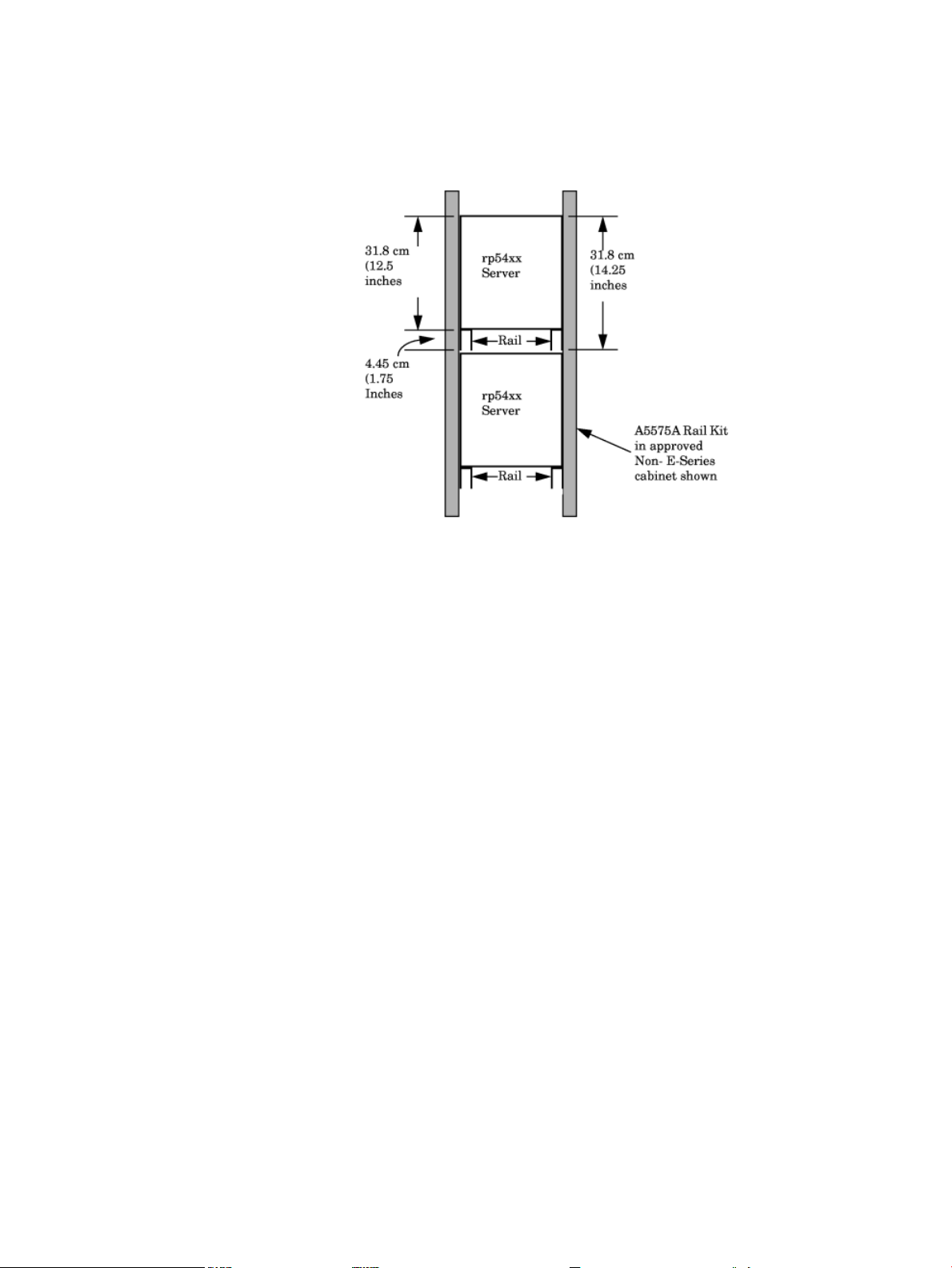
1. Locate the rail mounting height in the cabinet. Allow for the following space requirements:
• For each rp54xx server, allow 31.8cm (12.5 inches)vertically (7 EIAs or Rack Units (RUs).
• If installing the A5575A rail kit, allow an additional vertical 4.45cm (1.75 inches (1 EIA)
each set of rails.
2. Install sheet metal nut(s) in the vertical cabinet posts at the required height for the kit being
installed:
• Install the first nut either:
— 4.45 cm (1.75 Inches) above the top, or
— 31.8 cm (12.5 inches) below the bottom of the last server.
• If installing a A5562A rail kit, install the second nut in the next frame hole below the
first.
3. Hold the rail in place and insert and tighten the screws.
For installation of other qualified cabinet and rail combinations refer to the safety precautions
and instructions accompanying them.
Stationary L-Bracket Rail Assembly 27
Page 28

28
Page 29
3 Installing Additional Components
Additional Components
Some internal components are too delicate to be installed in the server prior to shipping. These
internal componentsare shipped withthe server, butare packed separately. They can be installed
after the cabinet has been unpacked and positioned.
Some ofthe internal components that are packed separately are not user-installable. To maintain
warranty validation, these items must be installed by a Hewlett-Packard Customer Engineer.
If you received either (or both) of the components listed below, contact your Hewlett-Packard
provider to arrange for installation.
• Central Processing Units (CPUs)
• Power Distribution Units (PDUs)
Installing Memory
Memory Configuration Rules
rp54xx servers have 16slots (8DIMM pairs) for memory DIMMs. These slots arenumbered 0a/b,
1a/b,... 7a/b. 8 of these slots (4a/b - 7a/b) are disabledon rp5400 servers. rp5450 servers canaccess
all slots. rp5400 and rp5450 servers have DIMM slots located on the System Board.
rp5470 servers install DIMMs using Memory Carriers. The Memory Carriers fit into slots on the
System Board.
The following rules govern the installation of memory DIMMs for rp5400, rp5450, and rp5470
servers:
• Memory must be installed in DIMM pairs.
• The capacity of DIMMs within a pair must be the same.
• Install DIMMs with the greatest capacity in the lowest slot numbers.
• Install DIMMs the following slot order: 0a/b, 1a/b, 2a/b, 3a/b, and so on.
Installing rp5400 and/or rp5450 DIMMs
1. Power down and unplug the rp54xx server.
CAUTION: DC voltages are present when the server is connected to AC power. Do not
install or service rp54xx internalcomponents while DC voltage is present. Failure toobserve
this precaution can result in damage to the server.
2. Loosen the captive T-15 screws that holdthe top cover in place, then grasp the strap handle,
raise the cover slightly, and pull the cover toward the front of the server to free the cover
tabs from the slots in the chassis. The air baffle will be exposed.
Additional Components 29
Page 30
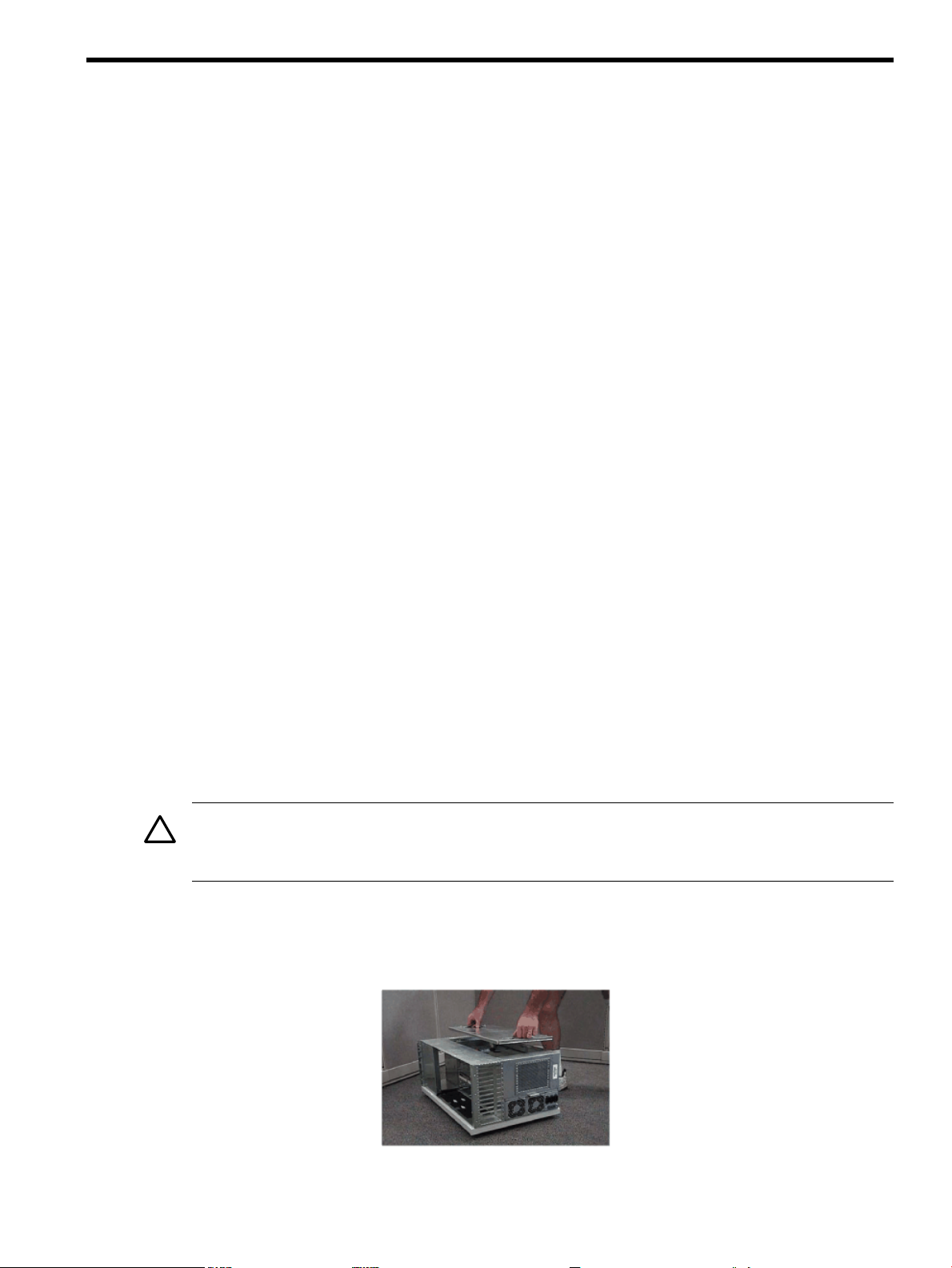
3. Make the top of the server accessible for service.
4. Loosen the captive T-15 screws on the air baffle. Grasp the two handles on the baffle, and
lift the baffle remove it.
CAUTION: Observe all ElectroStatic Discharge (ESD) precautions Do not touch internal
components. Failure to observe ESD precautions can cause damage to components.
5. Observe Electrostatic Discharge (ESD) precautions.
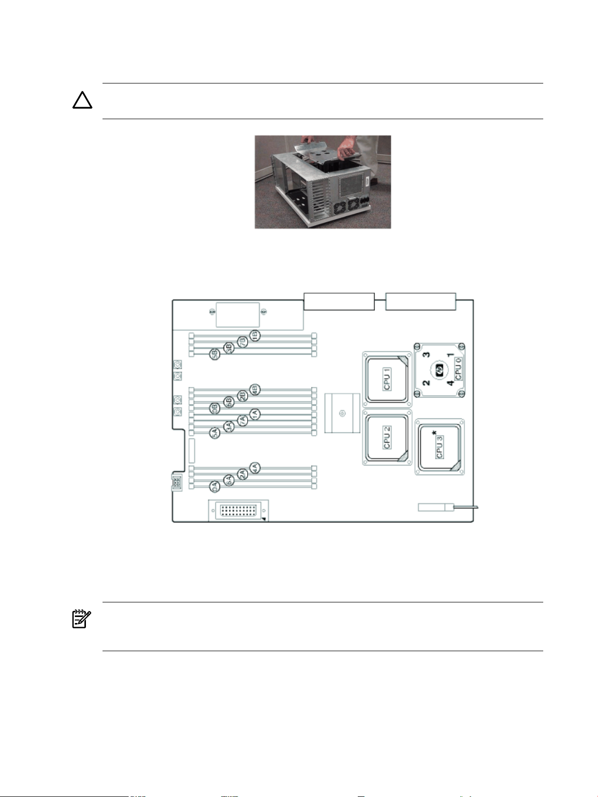
6. Refer to the following graphic for memory slot locations.
Locate the correct DIMM pair slots. Insert the DIMM connectors into the guides until the
card snaps firmly in place. It may be necessary to apply downward force using the palm of
your hand on the DIMM. Observe the top of the DIMM to make sure one side is not higher
than the other.
NOTE: It may be necessary to remove PSM 1 when installing a DIMM in slot 0a and PSM
0 when installing a DIMM in slot 1b. If either PSM is removed to install memory, ensure it
is re-installed.
7. Replace the air baffle. Tighten the four captive screws to secure the air baffle in place.
30 Installing Additional Components
Page 31

8. Replace the top cover. Tighten the four captive screws to secure the top cover in place.
9. For rack configurations, insert the rp54xx server back into the rack.
10. For deskside enclosure configurations, replace the deskside enclosure cover.
11. Power the rp54xx server on.
12. Use the BCH command in meto verify the system recognizes the memory that you have
just added.
Installing rp5470 DIMMs
DIMMs for the rp5470 system are installed in memory carriers instead of the system board, as
are the other rp54xx systems. However, rp5470 memory carriers are also located on the system
board, so the method for opening and closing the system is the same. Procedures for removing
and replacing theserver top andbaffle are listed below,without the pictures shownin thesection
titled, "Installing rp5400 and/or rp5450 DIMMs." If you wish to reveiw the pictures, please refer
to the aforementioned section.
1. Power down and unplug the rp54xx server.
NOTE: DC voltages are present when the server isconnected toAC power. Do not attempt
to install or service: CPUs, Memory, PSMs, the Platform Monitor or PCI I/O cards installed
in non-Turbo slots (1-6) while DC voltage is present. Failure to observe this warning may
result in damage to the server.
2. Make the top of the server accessible for service.
3. Loosen the captive T-15 screws that holdthe top cover in place, then grasp the strap handle,
raise the cover slightly, and pull the cover toward the front of the server to free the cover
tabs from the slots in the chassis. The air baffle will be exposed.
4. Loosen the four (4) captiveT-15 screws on the air baffle. Grasp thetwo handles on the baffle,
and lift and remove the baffle.
5. Observe Electrostatic Discharge (ESD) precautions.
6. Refer to the following graphic for Memory Carrier locations.
Installing Memory 31
Page 32

a. Locate the Memory Carrier and pull up on the extractor levers on each end of the
Memory Carrier to unseat the Memory Carrier from its socket.
b. When the Memory Carrier unseatsfrom the socket, pullit awayfrom the System Board.
c. Loosen the captivescrews that secure the DIMM Clip and remove the DIMM Clip from
the Memory Carrier.
d. Seat the memory DIMM into its socket on the Memory Carrier.
e. Press theextractor levers on each end of the memory DIMM slot inward until the levers
snap into place.
f. Attach the Memory Clip to the Memory Carrier with the DIMM slot markings on the
top of the Memory Clip aligned with the DIMM slot markings on the Memory Carrier.
g. Secure the Memory Clip using the captive screws.
h. Seat the Memory Carrier into the appropriate slot on the System Board.
i. Push down on the extractor levers and snap them into place.
7. Replace the air baffle. Tighten the four captive screws to secure the air baffle in place.
8. Replace the top cover. Slide the cover tabs into the slots in the chassis and close the cover.
Tighten the two captive screws to secure the top cover in place.
9. For rack configurations, insert the rp54xx server back into the rack.
10. For deskside enclosure configurations, replace the deskside enclosure cover.
11. Power the rp54xx server on.
12. Use the BCH command in meto verify the system recognizes the memory that you have
just added.
Installing Peripheral Component Interconnect (PCI) Cards
rp54xx servers have a total of 12 PCI I/O slots. Slots 1 and 2 are reserved for the LAN/SCSI and
GSP Core I/O cards, leaving 10 PCI I/O slots available for Customer use.
rp5400/rp5450 PCI Card Slots
For rp5400 and rp5450 models, 10 PCI I/O slots consist of Turbo and non-Turbo slots. Server PCI
slots are shown below.
32 Installing Additional Components
Page 33

• Slots 1 and 2 are reserved for the rp54xx LAN/SCSI and GSP (Guardian Service Processor)
Core I/O cards, respectively. Slots 1 and 2 are non-Turbo slots. Non-Turbo slots share a
single 250MB/s PCI bus and are incapable of HotPlug functionality. The server must be
turned off prior to removing or installing the LAN/SCSI or GSP cards in these slots.
• Slots 3 - 6 are non-Turbo slots. These four Non-Turbo slots share a single 250MB/s PCI bus,
run at33MHz and support 32 and 64-bit PCI cards.Non-Turbo slots are incapable ofHotPlug
functionality. The server must be turned off prior to removing or installing PCI cards in
these slots.
• Slots 7 - 12 are Turbo slots. Each Turbo slot has a dedicated 250MB/s PCI bus, run at 66MHz
and support 32 and 64-bit PCI cards. Turbo slots are HotPlug capable. Below each Turbo
slot is a plastic PCI card separator. The PCI card separator has two LEDs and a pull tab on
the outer edge. The LED's provide power and status for the slot. The pull tab allows the PCI
card to be easily removed.
rp5400 servers have access to slots 1, 2 and 8-12 while rp5450 servers have access to all (1-12)
slots.
NOTE: Slot 3 will become enabled on rp5400 servers with server firmware versions later than
40.48.
A slot 3 enabled label (A5576-84009) is available for rp5400 systems.
rp5470 PCI Card Slots
For rp5470 models, the 10 PCI I/O slots consist of Twin Turbo, Turbo, and non-Turbo slots. The
following illustration shows the PCI card slot layout.
Installing Peripheral Component Interconnect (PCI) Cards 33
Page 34

• Slots 1 and 2 are reserved for the rp54xx LAN/SCSI and GSP (Guardian Service Processor)
Core I/O cards, respectively. Slots 1 and 2 are non-Turbo slots. Non-Turbo slots share a
single 250MB/s PCI bus and are incapable of HotPlug functionality. The server must be
turned off prior to removing or installing the LAN/SCSI or GSP cards in these slots.
• Slots 3 and 4 are non-Turbo slots. These two Non-Turbo slots share a single 250MB/s PCI
bus, run at 33MHz and support 32 and 64-bit PCI cards. Non-Turbo slots are incapable of
HotPlug functionality. The server must be turned off prior to removing or installing PCI
cards in these slots.
• Slots 5 - 10 are Turbo slots. Each Turbo slot has a dedicated 250MB/s PCI bus, run at 66MHz
and support 32 and 64-bit PCI cards. Turbo slots are HotPlug capable. Below each Turbo
slot is a plastic PCI card separator. The PCI card separator has two LEDs and a pull tab on
the outer edge. The LED's provide power and status for the slot. The pull tab allows the PCI
card to be easily removed.
• Slots 11 and 12 are Twin Turbo slots. Each Twin Turbo slot has a dedicated 500MB/S PCI
bus, runs at 66 MHz, and supports 32- and 64-bit PCI cards. Twin Turbo slots are HotPlug
capable. Below each Twin Turbo slot is a plastic PCI card separator. The PCI card separator
has two LEDs and a pull tab on the outer edge. The LED's provide power and status for the
slot and the pull tab allows the PCI card to be easily removed.
rp5470 servers have access to all (1-12) slots.
PCI I/O Card Installation Restrictions
Restrictions applyregarding the installation of PCI I/O cards which containa PCI-to-PCI bridge:
• HP-UX boot is currently not supported for cards that contain a PCI-to-PCI bridge.
• HP-UX patches are required when more than one card containing a PCI-to-PCI bridge is
installed in non-Turbo slots.
PCI I/O Card Installation Order
The following table shows a standard factory PCI card installation that begins with slot 12. Use
this table as a guideline for installing PCI I/O cards in the field.
34 Installing Additional Components
Page 35

NOTE: A system shipped from the factory may have a different configuration than the same
system built in the field. For example: The factory will install the graphics card in slot 12 and
add other cards below. In the field, slot 12 may already be occupied by another PCI card. It is
acceptable for the graphics card to be installed in any available Turbo slot.
Number
BootMaxDescription (all are PCI cards)Product
Order*
A4926-600015No101000Base SX PCI LAN AdapterA4926A
A4926-600016No101000Base TX PCI LAN AdapterA4926A
A5846-600018YFC TacliteA5158A
A5486-600019No10Praesidium Speed CardA5486A
A5506-6010210No7/104 Port 100Base TX LAN AdapterA5506B
A5149-6000112Yes10Single Port Ultra 2 SCSI HBAA5149A
A4800-6700214Yes10FWD SCSI-2 adapterA4800A
NotesPart NumberLoad
3,8A4982-665011No1Graphics, Graphics CardA6150A
9A5838-600013NoComboA5838A
10A5483-600014No10ATM 622Mbps MMF AdapterA5483A
11A6092-600017NoHYPERFabricA6092A
1,2,6A5506-6010110No7/104 Port 100Base TX LAN AdapterA5506A
4A5150-6000111Yes10Dual Port Ultra 2 SCSI adapterA5150A
7,55063-132213No10High Perf 4 Ports Synchronous AdapterJ3526A
B5509-6600115No10100Base-T LAN AdapterA5230A
A3738-6000116No1010/100Base-T LAN AdapterA3738A
A3739-6000117No10Dual FDDI LAN AdapterA3739A
A5783-6010118No10Token Ring 4/16/100 Hardware AdapterA5783A
J3525-6000119No10Dual Port Synchronous AdapterJ3525A
J3593-6000120No1064 port Serial MUX system cardJ3593A
J3592-6010121No48 Port PCI Serial MUX cardJ3592A
A6150-6000122No1Graphics, USB CardA6150A
12,13A6150-600031No1Pinnacle 2 GraphicsA6150BX
A3686-600016No10Hyper Fabric 2 InterconnectA6386A
14A5506-6010210No10Quad Port 10/100B-TX LANA5506A
A6749-6000124No103.3v 64 Port Terminal MUXA6749A
A6748-6000125No103.3v 8 Port Terminal MUXA6748A
*In top down order.
Notes:
1. Card contains a PCI-to-PCI bridge.
2. Requires PHKL_20123, PHKL_20629 and PHNE_19826 or their superseded equivalents.
3. Not supported in non-Turbo slots. Install in Turbo slots only.
Installing Peripheral Component Interconnect (PCI) Cards 35
Page 36

4. Requires server firmware revision 39.46 or later.
5. Requires HP-UX 11.1
6. Maximum is 7 for HP-UX versions prior to 11.0. Maximum is 10 forHP-UX version11.1 and
later.
7. Requires PHKL_19543 and PHKL_19544 or their superseded equivalents.
8. Requires HP-UX11.0 Support Plus (IPR) 0006, June 2000 orlater.This product to be released
6/00.
9. Not supported in a shared slot (slots 3-4 for rp5470, slots 3-6 for rp5450, not applicable for
rp5400).
10. If you are installing ATM 622 cards in an rp5470 configuration, do not install them in slots
3 and 4 (shared slots).
11. Requires 768 MB for first card and 512 MB for each additional card.
12. Not supported in shared slots.
13. Max of 1. Needs USB card for keyboard and mouse.
14. Contains PCI bridge.
Installing a PCI Card
Follow these procedures to install a PCI card.
1. Power down and unplug the rp54xx server.
NOTE: DC voltages are present when the server isconnected toAC power. Do not attempt
to install or service: CPUs, Memory, PSMs, the Platform Monitor or PCI I/O cards installed
in non-Turbo slots (1-6) while DC voltage is present. Failure to observe this warning may
result in damage to the server.
2. Make the right side of the server accessible for service.
3. Using a Torx 15 screwdriver, loosen the captive screws on the right side panel. This panel
has a label which shows which PCI I/O slots are available and the corresponding paths. The
PCI I/O slot paths for rp5400, rp5450, and rp5470 are shown below.
rp5430/rp5470rp5450rp5400
Slot PathSlot TypePathSlot/TypePathSlot Type
0/10/0Twin Turbo0/4/0Turbo0/4/0Turbo12
0/12/0Twin Turbo0/7/0Turbo0/7/0Turbo11
0/8/0Turbo0/3/0Turbo0/3/0Turbo10
0/9/0Turbo0/6/0Turbo0/6/0Turbo9
0/3/0Turbo0/2/0Turbo0/2/0Turbo8
0/5/0TurboNot Available7
0/1/0SharedNot Available6
0/1/1SharedNot Available5
0/1/2SharedNot Available4
3
2
1
1
1
1
0/1/0Turbo
0/5/0Turbo
0/2/0Turbo
0/4/0Shared
0/4/2Shared0/1/3SharedNot Available
1 Slot is NOT AVAILABLE for rp5430.
2 Slot 3 becomes available with server firmware versions later than 40.48.
36 Installing Additional Components
GSPGSPGSP2
LAN/SCSILAN/SCSILAN/SCSI1
Page 37

4. Remove the PCI slot cover from the slot that will receive the PCI card. To remove the PCI
slot cover, slide the PCI slot cover away from the server.
5. Slide the PCI card connectors into the slot, snapping firmly in place. For full length (cards
that extend to the left side card guides) PCI cards, use the UPPER card guide.
6. At the rear of the chassis, connect the I/O cable to the card just installed.
7. Replace the right side panel and tighten the captive screws.
8. For rack configurations, insert the rp54xx server back into the rack.
9. For deskside enclosure configurations, replace the deskside enclosure cover.
10. Power the server on.
11. Use the server firmware in io command to verify the PCI cards are recognized by the
server. If AUTOBOOT is ON, it will be necessary to interrupt the boot process to get to the
server firmware Main Menu: Enter command or menu > prompt.
12. Boot HP-UX and run the ioscan utility to verify the system recognizes the new PCI card.
Installing Peripheral Component Interconnect (PCI) Cards 37
Page 38

Online Addition/Replacement (OLA/R) of PCI I/O cards
Beginning with HP-UX 11i (11.11) rp54xx servers support the on-line addition and replacement
of PCII/O cards. In order for this high availabilityfeature to be fully implemented, the following
server requirements must be met:
• rp5400A/rp5450A firmware must be later than 40.26 (rp5400B/rp5450B/rp5470A firmware
will support OLA/R upon its release).
• HP-UX operating system must be 11i (11.11) or later.
There is a bit that the HP-UX operating system examines to determine if the server hardware
and firmware is capable of OLA/R. This bit is controlled by server firmware. If the bit is ON,
OLA/R is possible (when requirements have been met). The bit was mistakenly set to ON for all
rp5400 andrp5450 revision A (rp5400A and rp5450A) servers. As a result, HP-UXmay incorrectly
identify these models as being OLA/R capable. In order to avoid this confusion, verify that the
correct level of server firmware is installed.
Installing Graphics
This section explains how to install rp54xx 2D graphics hardware. For a complete graphics
solution, three productsare required.The products listed beloware the only productssupported
on rp54xx servers.
• A6150A rp54xx Graphics Package
— Includes PCI graphics card
— Includes PCI USB (Universal Serial Bus) card
• A4983B Keyboard and Mouse Kit
— Includes mouse with 114" cable
— Includes keyboard with 109" cable
• D8910W (19") or D2847W (21)" Monitor
— Includes localized power cord and 75" 15-pin video cable
NOTE: rp54xx graphics requires HP-UX 11.0 Support Plus (IPR) 0006, June 2000 or later.
The photo below includes the A6150A, A4983B and D8910W products. The video cable for the
monitor is not shown. Black ESD mat not included.
rp54xx servers have a total of 12 PCI I/O slots. Slots 1 and 2 are reserved for the LAN/SCSI and
GSP Core I/O cards, leaving 10 PCI I/O slots available for Customer use. These 10 PCI I/O slots
consist of Turbo and non-Turbo slots.
38 Installing Additional Components
Page 39

• Slots 1 and 2 are reserved for the rp54xx LAN/SCSI and GSP (Guardian Service Processor)
Core I/O cards, respectively. Slots 1 and 2 are non-Turbo slots. Non-Turbo slots share a
single 250MB/s PCI bus. Non-Turbo slots are incapable of HotPlug functionality. The server
must be turned off prior to removing or installing the LAN/SCSI or GSP cards in these slots.
• Slots 3 - 6 are non-Turbo slots. These four Non-Turbo slots share a single 250MB/s PCI bus,
run at33MHz and support 32 and 64-bit PCI cards.Non-Turbo slots are incapable ofHotPlug
functionality. The server must be turned off prior to removing or installing PCI cards in
these slots.
• Slots 7 - 12 are Turbo slots. Each Turbo slot has a dedicated 250MB/s PCI bus, run at 66MHz
and support 32 and 64-bit PCI cards. Turbo slots are HotPlug capable. Below each Turbo
slot is a plastic PCI card separator. The PCI card separator has two LEDs and a pull tab on
the outer edge. The LED's provide power and status for the slot. The pull tab allows the PCI
card to be easily removed.
rp5400 servers can access PCI slots 1,2 and 8-12. rp5450/3000 servers can access all PCI slots.
Follow these procedures to install graphics cards.
1. Install HP-UX 11.0 Support Plus (IPR) 0006, June 2000 or later. This step ensures the
appropriate HP-UX drivers are installed.
2. Power down and unplug the rp54xx server.
NOTE: DC voltages are present when the server isconnected toAC power. Do not attempt
to install or service: CPUs, Memory, PSMs, the Platform Monitor or PCI I/O cards installed
in non-Turbo slots (1-6) while DC voltage is present. Failure to observe this warning may
result in damage to the server.
3. Make the right side of the server accessible for service.
4. Using a Torx 15 screwdriver, loosen the captive screws on the right side panel. This panel
has a label which shows which PCI I/O slots are available and the corresponding paths. The
label shown below is for an rp5400.
Installing Graphics 39
Page 40

5. Grasp the handle on the right rear panel and remove the panel from the side of the chassis.
The 12 PCI slots, numbered 1-12 from bottom to top, will be in view.
6. Remove the PCI slot cover from the slot that will receive the PCI card. To remove the PCI
slot cover, slide the PCI slot cover away from the server.
7. Center the graphics card within the space created by removing the PCI I/O slot cover. Slide
the cardtoward the edge connectors.Ensure the edgeconnectors on the card are in alignment
with the connectors of the slot. Apply pressure to the card until it snaps firmly in place.
Repeat process for USB card.
40 Installing Additional Components
Page 41

NOTE: The graphics card must be installed in any Turbo slot while the USB will work in
any slot. To reserve Turbo slots for high performance I/O cards, install the USB card in a
non-Turbo slot
8. At the rear of the chassis, connect the keyboard and mouse cables to the USB card. It does
not matter which connector is used for the keyboard or mouse.
9. Connect one end of the 15-pin video cable connector on the graphics card. This connector
is labeled "Graphics Display" and "Video Out". Connect the other end of this cable to the
graphics monitor.
Installing Graphics 41
Page 42

10. Replace the right side panel and tighten the captive screws.
11. For rack configurations, insert the rp54xx server back into the rack.
12. For deskside enclosure configurations, repalce the deskside enclosure cover.
13. Power the server on.
14. Use the server firmware in io command to verify the graphics cards are recognized by
the server. If AUTOBOOT is ON, it will be necessary to interrupt the boot process to get to
the server firmware Main Menu: Enter command or menu > prompt.
15. Boot HP-UX and run the ioscan utility to verify the system recognizes the new PCI card.
16. Logon as root and install X/CDE/Motif if not already installed.
Graphics Troubleshooting
This section describes how to troubleshoot common problems encountered during installation
or attempted use of graphics. The following system utilities can be used to display or set the
graphics configuration:
• /opt/graphics/common/bin/graphinfo allows you to display the current graphics
configuration and the graphics drivers that are being used.
• /opt/graphics/common/bin/setmon allows you to reconfigure the monitor type.
• The display menu of the HP-UX System Administration Manager (SAM) utility allows
you to configure the X-Server and set the monitor type.
42 Installing Additional Components
Page 43

• On-line diagnostics provide information, verify and diagnose coverage forthe graphics and
USB cards.Off-line diagnostics do not exist for either the graphics or USB card.
• The HP-UX ioscan utility can be used to verify the HP-UX operating system recognized
the hardware.
Symptom: CDE will not come up.
1. Ensure /dev/crt was created. If not created, use insf -e to create.
2. Ensure the system is at run level 3. Use who -r to determine run level. Use init 3 to
change to run level 3.
3. Ensure dt is enabled. Use /usr/dt/bin/dtconfig -eto enable dt.
4. Ensure /etc/dt/config/Xservers exists. If not, use
/usr/dt/config/dtrc.d/20_graph_conf to create.
5. Ensure the line: * Local local@console /usr/bin/X11/X :0 is not commented out of the
/etc/dt/config/Xservers file.
6. Reboot HP-UX.
Symptom: HP-UX does not recognize the graphics cards. unknown appears in the ioscan output
for these cards .
1. Examine the output of the swlist command to ensure the correct version of HP-UX is
installed.
2. Update HP-UX as necessary
Installing Disk Drives
rp54xx servers support up to four optional internal hard drives. These drives must be installed
in the following sequence:
It is not necessary to shutdown the HP-UX operating system or power off the server to install a
new disk. Follow this procedure to add internal hard disk drives to your rp54xx server.
1. If a front bezel is installed on the face of the server, open the right-hand panel to gain access
to the disk slots.
2. Remove the disk drive slot cover.
3. Insert the new disk drive into the slot until the rear connectors snap into place in the card
guide. As shown in the following graphic, the notches at the top of the disk drives must
snap over the small brackets in the disk bay to ensure a firm connection.
Installing Disk Drives 43
Page 44

4. Secure the connection by pushing the blue release lever closed.
5. Refer to HP-UX documentation to configure the new disk.
44 Installing Additional Components
Page 45

4 Cable Connections
Core I/O Connections
The following paragraphs describe the indicators and connections of the rp54xx Core I/O. Core
I/O consists of a LAN/SCSIcard in slot 1 (lower slot in graphic) anda GuardianService Processor
(GSP) in slot 2 (upper slot in graphic). There are two versions of GSP, revision A and revision B.
Revision A GSP
The followinggraphic shows the indicators and connectorsfor therevision A GSP and LAN/SCSI
Core I/O boards.
1. 10-Base-T LAN (RJ-45) Connector
GSP LAN.
2. Green/Red (Upper LED)
Green = GSP Power On.
Flashing Green = LAN Receive.
Red = Guardian Support Processor Test Failed.
3. Green/Red, (Lower LED)
Green = Link OK.
Flashing Green = LAN Transmit.
Red = Guardian Support Processor Test Failed.
4. Console/UPS/Remote Connector (D-Type 25-Pin female).
Requires an A5191-63001 "W" adapter cable
5. 10/100 Base-T = Primary LAN (RJ-45) Connection
Path 0/0/0/0
6. Green/Yellow (Upper LED)
Green = 100 Base-T Mode
Green Blinking = 100 Base-T Receiving
Core I/O Connections 45
Page 46

Amber = 10 Base-T Mode
Amber Blinking = 10 Base-T Receiving
7. Green (Lower LED)
Green = Link OK (10/100 Base-T Mode indicated by LED #6)
Green Blinking = Transmitting
8. Ultra-2 SCSI Connector (68-Pin VHDCI SCSI)
Path 0/0/1/0
9. SCSI Mode (Green, Upper LED)
On = Low Voltage Differential (LVD) Mode.
Off = Single Ended Mode.
10. SCSI Terminator Power (Amber, Lower LED)
On = Terminator power present
Off = Terminator power Not present.
Revision B GSP
The following graphicshows theindicators and connectorsfor the revision B GSPand LAN/SCSI
Core I/O boards.
1. 10/100-Base-T LAN (RJ-45) Connector.
GSP LAN.
2. Green/Red (Upper LED).
Green = GSP Power On.
Red = Guardian Support Processor Test Failed.
3. Green/Yellow, (Lower LED).
Green = 100 Base-T Link OK.
Flashing Green = 100 Base-T LAN Activity.
Yellow = 10 Base-T Link OK.
Flashing Yellow = 10 Base -T LAN Activity.
46 Cable Connections
Page 47

4. Console/UPS/Remote Connector (D-Type 25-Pin female).
Requires an A6144-63001 "M" adapter cable.
5. 10/100 Base-T = Primary LAN (RJ-45) Connection.
Path 0/0/0/0.
6. Green/Yellow (Upper LED).
Green = 100 Base-T Mode.
Green Blinking = 100 Base-T Receiving.
Amber = 10 Base-T Mode.
Amber Blinking = 10 Base-T Receiving.
7. Green (Lower LED).
Green = Link OK (10/100 Base-T Mode indicated by LED #6).
Green Blinking = Transmitting.
8. Ultra-2 SCSI Connector (68-Pin VHDCI SCSI).
Path 0/0/1/0.
9. SCSI Mode (Green, Upper LED)
On = Low Voltage Differential (LVD) Mode.
Off = Single Ended Mode.
10. SCSI Terminator Power (Amber, Lower LED)
On = Terminator power present
Off = Terminator power Not present.
Guardian Service Processor (GSP) Overview
This sectionprovides an overview of the GuardianService Processor(GSP). The GSP is an always
on, dedicated service processor that monitors system power, cooling and configuration, and
provides console communications. Power and cooling information is obtained via an interface
to the platform monitor card. Configuration information is obtained via connection to the Serial
Presence Detect (SPD) bus. The GSP can only be installed in slot 2 and must be present for the
server to power up.
The GSPhas downloadable firmware which can be updatedindependent of the HP-UX operating
system. GSP firmware updates can occur anytime the GSP is active. If the DC power switch is
OFF, the GSPis stilloperational and GSPfirmware updatescan stilloccur.GSP firmware updates
may be performed by customers.
If the GSP becomes hung, it is possible to reset the GSP without impacting the server. The GSP
may be reset via the GSP RESET button on the right side of the card. The PCI cover panel (right
side panel) must first be removed to allow access to the right side if the GSP card.
The GSP has two connectors on the bulkhead. An RJ-45 for LAN connections and a female DB25
connector for RS-232 connections. Attach either a "W" or an "M" cable to the DB25 connector to
provide individual output for CONSOLE, REMOTE and UPS.
To accessthe GSP from the local ASCII console, type control b and theGSP> prompt willappear.
It may be necessary to type control Ecf first. To exit the GSP, type GSP>co.
The GSPwas originallya corecomponent of the revision A rp5400(A5576A) and rp5450(A5191A)
servers. Beginning with introduction of the revision B rp5400 (A5576B), rp5450 (A5191B), and
rp5470 servers the GSP became a separate, must order product (A6696A).
There are two revisions of rp54xx GSP: rev A (A6696A) and rev B (A6696B). Both GSPs must be
installed in order for the server to power up.
Guardian Service Processor (GSP) Overview 47
Page 48

GSP LAN
This LAN is exclusively for LAN console access and is not configurable via HP-UX. The LAN is
configured via GSP commands. Hostname, IP, gateway and subnet mask parameters may be set
via the GSP>lc command. The GSP may also initiate ping via the GSP>xd command.
GSP RS-232
The DB25 connector on the GSP is used for RS-232 communications to a local console (via
CONSOLE connector), a remote console via modem (REMOTE connector), and a UPS (UPS
connector). The baud rate, term type, etc., of the CONSOLE and REMOTE ports are configured
via GSP>ca command.
The GSP supports VT100 and HPTERM terminal emulation. For correct communications, the
GSP and RS-232 device must use the same terminal emulation and baud rates.
GSP Features
The revision A GSP provides a 10 base-T LAN connector for LAN console access and a DB-25
connector to which the A5191-63001 W-cable connects. The W-cable provides REMOTE, UPS,
and CONSOLE DB-9 connectors.
Features of the revision A GSP are:
• 10 Base-T LAN connector for revision A GSP
• 10/100 Base-T LAN connector for revision B GSP
• On-board processor dedicated to GSP functions
• Error logging and notification
• Display of system alerts and selftest chassis codes
• Powered by 15 VDC housekeeping power that is present when the front panel switch is off
• Power and configuration monitoring
• RS-232, LAN, REMOTE and WEB console access
• Administrator and user security
• Alphanumeric paging.
There are two revisions of rp54xx GSP: revision A (A6696A) and revision B (A6696B). Due to
significant hardware differences between the revision A and B GSP, each GSP requires it's own
firmware. Revision A GSP firmware can only be installed in a revision A GSP and revision B
GSP firmware can only be installed in a revision B GSP. The hardware differences are necessary
to incorporate the embedded web access, 10/100 Base-t LAN, and faster GSP processor.
The GSP provides four types of console access: RS-232, Remote, LAN and Web. Console
information is mirrored to all four console types. Refer to Configure System Consoles for more
information.
The GSPwas originallya corecomponent of the revision A rp5400(A5576A) and rp5450(A5191A)
servers. Beginning with introduction of the revision B rp5400 (A5576B), rp5450 (A5191B), and
rp5470 servers the GSP became a separate, must order product (A6696A).
Revision A GSP
The revision A GSP is identified by product number A6696A and part numbers: A5191-60012,
A5191-69012, and A5191-69112.
The revision A GSP requires a "W" cable to be attached to the DB25 connector. The part number
of the"W" is A5191-63001. The"W" cable provides femaleDB9 connectorsfor CONSOLE, REMOTE
and UPS. The maximum supported baud rate for the CONSOLE and REMOTE connectors is
19200 baud and 1200 baud for the UPS.
The pathsfor the CONSOLE, UPS, and REMOTEare 0/0/4/0.0,0/0/4/0.1, and 0/0/4/0.2respectively.
48 Cable Connections
Page 49

For therev A GSP, the web console is accomplished by shippingone J3591A Secure WebConsole
with each rp54xx server. The Secure Web Console can be used in place of an ASCII console to
provide console access via a web connection. If you are installing an rp54xx server that does not
have an ASCII console, you may use the Secure Web Console as the console. However, you must
first configure the Secure Web Console. Refer to Secure Web Console Installation for more
information on SWC Installation/Configuration.
Revision B GSP
The revision B GSP is identified by product number A6696B and part numbers: A6144-60012,
A6144-69012, and A6144-69112.
The revision B GSP requires an "M" cable to be attached to the DB25 connector. The part number
of the "M" cable is A6144-63001. The "M" cable provides female DB9 connectors for CONSOLE,
REMOTE, and UPS. The maximum supported baud rate for the CONSOLE and REMOTE
connectors is 38400 baud and 1200 baud for the UPS.
The pathsfor the CONSOLE, UPS, and REMOTE are 0/0/4/1.0,0/0/4/1.1 and0/0/4/1.2 respectively.
Configure System Consoles
rp54xx servers provide RS-232, REMOTE, LAN and WEB console access. All console access
involves the Guardian Service Processor(GSP). rp54xxservers use either a revision A or revision
B GSP. Below is an illustration of the console access provided by the revision A GSP.
The revision B GSP has embedded web access, eliminating the need for an external Secure Web
Console (SWC). Below is an illustration of the console access provided by the revision A GSP.
Configure System Consoles 49
Page 50

GSP Cables
Both the revision A and B GSPsprovide a DB-25 connector for RS-232 communications. Connect
the A5191-63001 W- cable to the revision A GSP DB25 connector or connect the A6144-63001
M-cable to the revision B GSP DB25 connector. These cables provide individual DB9 connectors
for REMOTE, UPS and CONSOLE.
NOTE: Use the A5191-63001 W-cable with revision A GSP and A6144-63001 M-cable with
revision B GSP only. Failure to use the right cable can result in reduced functionality.
The Wand M-cables are slightly different. The W-cable hasfull RS-232capability on the REMOTE
and CONSOLE connectors and partial RS-232 capability on the UPS connector. The M-cable has
full RS-232 capability on the REMOTE and UPS connectors and partial RS-232 capability on the
CONSOLE connector. The cable change is to be consistent with rp54xx functionality. The cables
are differentcolors to easilytell them apart. The W-cable is gray andhas partnumber A5191-63001.
The M-cable is black and has part number A6144-63001.
Configure RS-232 Console
The physical connections for an RS-232 console include attaching the correct cable to the GSP.
Next, connect the 24542G cable (supplied) to the CONSOLE connector and the serial port of the
ASCII console. A personal computer (PC) running terminal emulation software may be used in
place of an ASCII console. Refer to the illustration below for RS-232 console.
50 Cable Connections
Page 51

1. The GSP is located in slot 2 of the rp54xx' rear card cage. Connect the 25-pin end of:
• the A5191-63001 W-cable to the 25-pin connector on the revision A GSP card
(A5191-60012) OR
• the A6144-63001 M-cable to the 25-pin connector on the revision B GSP card
(A6144-60012)
2. Connect the 9-pin "Console" connector of either the W or M-cable to the 9-pin D-type
connector of a 24542G RS-232 cable.
3. Connect the 25-pin end of the 24542G serial cable to the serial/RS232 port on the ASCII
console. (RS232 Serial Port labeling may vary depending on manufacturer.)
4. Connect the System Console to input AC power.
5. Turn the System Console AC power switch to ON.
After the physical connections have been made, configure the ASCII console. When using the
C1099A Terminal Console, the default settings are recommended. Refer to the C1099A Terminal
Console operating manual for instructions on how to obtain default settings.
The HP 700 series console may also be used as an ASCII console. Both the C1099A Terminal
Console and S700 consoles support HPterm and VT100 emulations. The emulation of the GSP
and ASCII console need not match for communications between them to occur. However, to
ensure proper communications, HP recommends the ASCII console and GSP use the same
emulation. HP also recommends that other configurable parameters on the GSP match those of
the ASCII console. Baud rate, start/stop bits, etc... The default emulation of the GSP is VT100.
Below is a procedure to configure a HP 700 serial console for VT100 emulation.
HP 700 Series System Console Configuration
The following describes the steps required to configure the HP 700 series terminal for VT-100
mode for operation with an rp54xx server.
Although any terminal capable of operating in VT-100 mode can be used, the HP700 series
terminal is used here as an example because it is fairly common and it's configuration is typical
of many terminals currently in use.
HP700 VT-100 Mode Configuration
The following procedure outlines the steps to configure the HP700 series terminal for VT100
operation.
Configure System Consoles 51
Page 52

NOTE: You may use either the arrow keys or the tab key to move between the setting options
on the screen.
1. Press [config keys] function key. [f8]
2. Press [terminal config] function key. [f5]
3. Move to Terminal ID and enter "vt100".
4. Move to Set TermMode and, using the [Prev] and [Next] keys, select "EM100".
5. Press the [config keys] function key. [f8]
6. Press the [ansi config] function key. [f6]
7. Move to "multipage" and, using the [Prev] and [Next] keys, select "yes".
(Enables screen scrolling).
8. Move to Backspace Del and, using the [Prev] and [Next] keys, select "Backspace/Del".
9. Move to EM100 ID and, using the [Prev] and [Next] keys, select "EM100".
Configure the Asynchronous Values of the GSP
After theASCII console has been configured andphysical connectionsmade, make any necessary
changes to the asynchronous values of the GSP.
1. Access the GSP with the ctrl+b entry. The GSP will respond with a GSP> prompt.
2. At the GSP prompt, enter the Configure Asynchronous (ca) command:
The ca command will start a series of prompts. Respond to each prompt with the appropriate
information.
Example 4-1 CA command
Leaving Console Mode - you may lose write access. When Console Mode returns, type ^Ecf to get console write
access.
GSP Host Name: fesrhapgsp
GSP> ca
CA This command allows you to modify the local and remote modem serial portconfigurations.
Current configuration settings:
Local Console Serial Port bit rate: 9600 bits/s
Local Console Serial Port Flow Control: Software
Local Console Serial Port Terminal Type: vt100
Remote Console Serial Port Modem Protocol: CCITT Remote Console Serial Port Modem
bit rate: 19200 bits/s
Remote Console Serial Port Modem Flow Control: Software
Remote Console Serial Port Modem Transmit Configuration Strings: Enabled
Remote Console Serial Port Modem Presence: always connected
Do you want to modify the Local Console Serial Port settings? (Y/[N])
Do you want to modify the Remote Console Serial Port Modem settings? (Y/[N])
GSP Host Name: fesrhapgsp
If necessary, use the GSP help facility by typing GSP>he. Once in the help facility, type the
command need help with. Use LI for a list of commands.
The following baud rates are recommended for the revision A GSP:
• Console: 19200
• Remote: 19200
• UPS: 1200
The following baud rates are recommended for the revision B GSP:
52 Cable Connections
Page 53

• Console: 38400
• Remote: 38400
• UPS: 1200
Configure Remote Console
The remote console allows console access via modem connections. Below is an illustration of the
REMOTE console.
The GSP>ca command is used to configure asynchronous settings for the REMOTE console.
Baud rates and emulations should match between the modems, remote ASCII terminal and the
GSP. Refer to, "Configure RS232 Console" for information about setting these values.
Configure the LAN Console
The LAN console allows you to access the console from the LAN using TelNet or http (revision
B GSP only) protocols. Below is an illustration of the LAN console.
The configuration of the LANconsole of both therevision A and BGSPs may be donefrom either
an ASCII console or the external Secure Web Console. For the revision B GSP, an IP may be
assigned via LAN by pinging the LAN from a PC or workstation.
Configure System Consoles 53
Page 54

Configuring the GSP LAN Port via an ASCII console
The LAN port of the GSP allows connection via TelNet or http connections. Once the LAN
parameters are configured, the console may be accessed via a TelNet connection or via a web
browser (revision B GSP only). The default IP of the GSP LAN is 127.0.0.1.
NOTE: The GSP has a separate LAN port from the system LAN port. It will need a separate
LAN drop, IP address, and networking information from the port used by HP-UX.
Before starting this procedure, you will need to know the following information:
• I.P. address (for GSP)
• Subnet mask
• Gateway address
• Hostname (this is used when messages are logged or printed)
To configure the GSP LAN port, perform the following steps:
1. Access the GSP with the ctrl+b entry.
2. At the GSP prompt, enter the LAN Configuration (lc) command:
GSP> lc
The lc command will start a series of prompts. Respond to each prompt with the appropriate
information.
Example 4-2 LC command
Leaving Console Mode - you may lose write access. When Console Mode returns, type ^Ecf to get console write
access.
GSP Host Name: fesrhapgsp
GSP> lc
LC This command allows you to modify the LAN configuration.
Current configuration:
MAC Address: 0x00306e050a63
IP Address: 15.8.133.185
GSP Host Name: fesrhapgsp
Subnet Mask: 255.255.248.0
Gateway: 15.8.128.1
Web Console Port Number: 2023
Do you want to modify the LAN configuration? (Y/[N])
GSP Host Name: fesrhapgsp
The revision B GSP introduces a configurableWebConsole Port Numberparameter. The default
value is 2023. Once the GSP LAN is configured, it is accessible via either TelNet or web
connections.
Configuring the GSP LAN Port via LAN
The revisionB GSP LAN port can beassigned an IPaddress without using theLAN Configuration
(lc) commandvia an ASCII console. This section describes how to assign the IP address allowing
web access. Onceweb access isaccomplished, usethe lc command toconfigure remainingnetwork
parameters.
54 Cable Connections
Page 55

NOTE: The GSP LAN port is separate from the system LAN port. It will need a separate LAN
drop, IP address, and networking information from the port used by HP-UX.
Before starting this procedure, you will need to know the following information:
• I.P. address (for GSP)
• Subnet mask
• Gateway address
• Hostname (this is used when messages are logged or printed)
To configure the GSP LAN port via LAN, perform the following steps:
NOTE: The GSP must be on the same subnet as the system being used to remotely configure
the LAN port. If it is not, the remote configuration will be unsuccessful.
1. Determine the MAC address of the revision B GSP by examining the GSP MAC address
label on the rear of the server.
2. Use the route add command to add the I.P address of the GSP and remote system to the
router.
3. Use the arp command to add an ARP entry for the IP address using the GSP MAC address.
• For HP-UX systems, the format of the MAC address is 00:30:6e:05:0a:ea
• For MS DOS systems, the format of the MAC address is 00-30-6e-05-0a-ea
4. Use the ping command to assign the I.P address for the GSP.
5. The revision B GSP is now accessible via LAN. Access the GSP and configure remaining
network parameters using the LAN Configuration (lc) command:
GSP> lc
The lc command will start a series of prompts. Respond to each prompt with the appropriate
information.
Configure the Web Console
For the revision A GSP, the web console is accomplished via the J3591A Secure Web Console.
Below is an illustration of the web console for the revision A GSP.
Refer to, "Install a SecureWeb Console" formore information on SecureWeb Console installation
and configuration.
Example 4-3 LAN Configuration from a PC
Configure System Consoles 55
Page 56

For the revision B GSP, the web console is an embedded feature. The steps to configure a web
console are the same as configuring a LAN console. Refer to, "Configure the LAN Console."
Once the LAN has been configured, access the web console by pointing a web browser, on the
same subnet, to the IP of the GSP LAN.
Two browser windows will appear: a window with a white background and the HP invent logo
and a separate GSP window with a black background.
56 Cable Connections
Page 57

Example 4-4 GSP Browser Window
Use the SETTINGS menu bar to configure web browser emulation. The GSP window also has
its own HELP facility.
Example 4-5 GSP Web Browser Help Screen
When the separateGSP window isclosed, it appearsin the HP invent window withZoom In/Out
above it. Click on the Zoom In/Out bar to generate a separate GSP window.
Configure System Consoles 57
Page 58

Example 4-6 Combined GSP Browser Window
There isnot a separateadministration "layer" when usingthe embeddedweb access of therevision
B GSP. Web console access via the external Secure Web Console required that you first logon to
the SWC, thenclick on ACCESSCONSOLE. User configurationwas alsoperformed at theSecure
Web Console. However, the revision B GSP web console does not require this additional step.
When you point the web browser at the IP of the GSP LAN, you are directly connected to the
GSP. The web console part of the GSP employs the same users as the GSP.
Secure Web Console Installation
The following section describes installation of the HP Secure Web Console on inside of the rear
door of a rack-mounted rp54xx server.
For technical, installation, and configuration instructions for the Secure Web Console, refer to
the following URLs on the Internet:
General information:
http://www.hp.com/
Documentation:
http://docs.hp.com
http://www.hp.com/go/hp9000_servers-docs
58 Cable Connections
Page 59

NOTE: Either the system console (HP series 700 terminal) or the HP Secure Web Console may
be installed on an rp54xx server, but not at the same time. Both console types use the same DB9
type LAN Console connector.
To install the HP Secure Web Console on an rp54xx server, refer to the previous figure and the
HP Secure Web Console documentation, then proceed as follows:
1. Install the wire mounting bracket by carefullyinserting the two topprongs throughthe vent
grill in the rear door of the cabinet as shown above. Position the bracket toward the hinge
side of the door.
2. Place the Secure Web Console power supply into the bottom portion of the wire mounting
bracket as shown.
3. Connect one end of the power cable to the power supply where indicated.
4. Position the Secure Web Console unit in the mounting bracket.
Secure Web Console Installation 59
Page 60

5. Connect the DC out cable from the power supply to the Secure Web Console.
6. Connect oneend of the AC power cord (supplied) to the Secure Web Console power supply.
7. Connect the other end of the AC power cord to an available receptacle.
On a PDU if in a cabinet.
In an available wall outlet if in a Deskside enclosure.
8. Connect the 9-pin end of the RS-232 cable (Supplied) to the connector labeled CONSOLE
on the A5591-63002 "W-type" adapter cable.
9. CAUTION: To prevent unauthorized access to your rp54xx system, do not connect the
other end of the serial cable to the Secure Web Console until both the server and the Web
Console have both been fully configured.
10. Connect one end of a LAN cable to RJ-45 connector labeled 10-Base-T on the Secure Web
Console.
11. Connect the other end of the same LAN cable to your site LAN.
12. Configure the SecureWeb Console in accordance withthe documentationthat was provided
with it or refer to http://docs.hp.com or http://www.hp.com/go/hp9000_servers-docs
13. Once the Web Console has been properly configured, the remaining end of the serial cable
between the server and the Web Console may be connected.
GSP Configurable Parameters
Once a system console is configured, additional GSP parameters may be set. For a complete list
use the GSP>he command to access the on-line help facility.
Examples of three configurable parameters follow.
Adding Users
The GSP provides a maximum of 20 users (one administrator and 19 operators). By design, the
first user added to the GSP becomes the GSP administrator. Only the GSP administrator can add
or remove users or change the GSP configuration.
60 Cable Connections
Page 61

NOTE: Before starting this procedure, you will need to know the following information:
• User's name
• Organization's name
• Login name
• User's password
To add a user, perform the following steps:
1. Access the GSP with the ctrl+b entry.
2. At the GSP prompt, enter the Security options and access control (SO) command:
GSP> so
3. The first prompt you will see with the so command is for GSP wide parameters:
GSP wide parameters are:
Login Timeout: 1 minutes.
. Number of password Faults allowed: 3
. Flow Control Timeout: 5 minutes.
Do you want to modify the GSP wide parameters? (Y / [N]) __
At this point you can modify the GSP wide parameters, or continue with adding users. To
add users, respond N for no.
NOTE: If this is the first time users are being added, the first user added will be the GSP
administrator.
If this is not the first time you are adding users (you are adding additional users), you will
need to step through all current users to reach the next available user prompt.
4. The next prompt that appears will ask the following question:
Do you want to modify the user number 1 parameters? (Y/[N]/Q to quit) __
Follow the series of prompts to enter all the required fields for adding a user.
CAUTION: Be sure to read each prompt carefully and enter the correct response. A missed or
incorrect entry could deny entry to that user.
The following is an example of an added user's information:
. User's Name: Joe Smith
. Organization's Name: IT Support
. Dial-back configuration: Disabled
. Access Level: Operator
. Mode: multiple
. User's state: enabled
For the number 1 user, the Access level is administrator. The Mode entry of single only allows entry for that
user one time, then access will be denied. A Mode entry of multiple allows unlimited entries into the GSP.
Removing Users
You can remove (disable) a GSP user with the same Security options and access control (SO)
command used to add a user.
To remove a user, perform the following steps:
1. Access the GSP with the ctrl+b entry.
2. At the GSP prompt, enter the Security options and access control (SO) command:
GSP> so
3. The first prompt you will see with the SO command is for GSP-wide parameters:
GSP wide parameters are:
. Login Timeout: 1 minutes.
. Number of password Faults allowed: 3
GSP Configurable Parameters 61
Page 62

. Flow Control Timeout: 5 minutes.
Do you want to modify the GSP wide parameters? (Y / [N]) __
At this point you can modify the GSP wide parameters, or continue with removing a user.
To remove users, respond N for no.
NOTE: You will have to step through each user number until you reach the user to be
removed.
4. When you access the number of the user to be removed, you must change the data in the
prompts for that number.
It is important that, at a minimum, you need to modify the User's state to Disabled.
Return the GSP to Default Configurations
The Default Configuration (dc) command is used to reset all or some of the GSP values to the
default values. To return GSP values to default configurations, perform the following steps:
1. Access the GSP with the ctrl+b entry.
2. At the GSP prompt, enter the Default Configuration (dc) command:
GSP> dc
3. Follow the prompts for the dc command, and be sure to have the change information
available.
CAUTION: When the Security configuration is reset, all users are removed, including the GSP
administrator. It also disables the remote. Remote must be re-enabled through the main console
using the Enable Remote (er) command.
rp54xx Server Boot Process
The length of time an rp54xx server will require to complete the boot process depends on the
number of processors and the amount of RAM installed. Average configurations can take more
than 20 minutes.
The boot process consists of the following main steps:
62 Cable Connections
Page 63

During the Boot process a variety of errors or problems can occur as shown below:
rp54xx Server Boot Process 63
Page 64

Initial Power-up
The following section describes the process of applying power to the rp54xx server and booting
the system to the UNIX Login prompt. The amount of time it takes to go through self-test then
boot thesystem will vary widely depending on hardware configuration. The following provides
a "typical" procedure. Yours may vary depending on software and hardware installed:
1. Apply AC Power to the system console.
2. Apply power to the rp54xx server by turning the front panel switch to ON.
64 Cable Connections
Page 65

3. Several self-test boot progress screens will be displayed andwill scroll rapidlyup thescreen.
Some tests may pause for up to one minute while the test completes.
The following examples of theforward progressscreens are typical of thescreens displayed.
4. When the initial power-up boot process completes in approximately one to five minutes,
the BCH main menu will be displayed:
rp54xx Server Boot Process 65
Page 66

5. To start theboot processusing the primaryboot path, enterBO PRI, atBoot Console Handler
BCH main menu prompt and press <ENTER>.
NOTE: Booting a system toa UNIX login prompt from BCHmain menu can take 20 minutes
or longer depending on your software and hardware configuration.
6. Once the system reaches the UNIX login prompt the following will be displayed on the
console screen:.
66 Cable Connections
Page 67

5 Utilities
Configuring the Rev A Guardian Service Processor (GSP)
The RevA Guardian Service Processor (GSP) is a residentprocessor withinthe system thatallows
the local or remote system administrator to monitor and perform administrator functions. This
section provides configuration procedures that will instruct you to:
• Configure the LAN port
• Add or delete users (maximum of 20)
• Change the default GSP configuration
Go to the appropriate section for the task that you wish to accomplish.
Configuring the GSP LAN Port
Perform the LAN configuration from thesystems local port (either console or the HP secure web
console).
NOTE: The GSP has a separate LAN port from the system LAN port. It will need a separate
LAN drop, IP address, and networking information from the port used by HP-UX.
Before starting this procedure, you will need to know the following information:
• I.P. address (for GSP)
• Subnet mask
• Gateway address
• Hostname (this is used when messages are logged or printed).
To configure the GSP LAN port, perform the following steps:
1. Go into the GSP with the ctrl+b entry.
2. At the GSP prompt, enter the LAN Configuration (lc) command:
GSP> lc
The lc command will start a series of prompts. Respond to each prompt with the appropriate
information.
Adding Users
The GSP can only have a maximum of 20 users (one administrator and 19 operators). By design,
the first user added to the GSP becomes the GSP administrator. Only the GSP administrator can
add or remove users or change the GSP configuration.
NOTE: Before starting this procedure, you will need to know the following information:
• User's name
• Organization's name
• Login name
• User's password
To add a user, perform the following steps:
1. Enter the GSP with the ctrl+b entry.
2. At the GSP prompt, enter the Security options and access control (SO) command:
GSP> so
3. The first prompt you see with the so command is for GSP-wide parameters:
Configuring the Rev A Guardian Service Processor (GSP) 67
Page 68

GSP wide parameters are:
Login Timeout: 1 minutes.
. Number of password Faults allowed: 3
. Flow Control Timeout: 5 minutes.
Do you want to modify the GSP wide parameters? (Y / [N]) __
At this point you can modify the GSP-wide parameters or continue adding users. To add
users, enter N for no.
NOTE: If this is the first time users are being added, the first user added will be the GSP
administrator.
If this is not the first time you are adding users (you are adding additional users), you will
need to step through all current users to reach the next available user prompt.
4. The next prompt that appears will ask the following question:
Do you want to modify the user number 1 parameters? (Y/[N]/Q to quit) __
Follow the series of prompts to enter all the required fields for adding a user.
CAUTION: Be sure to read each prompt carefully and enter the correct response. A missed or
incorrect entry will deny entry to that user.
The following is an example of an added users information:
. User's Name: Joe Smith
. Organization's Name: IT Support
. Dial-back configuration: Disabled
. Access Level: Operator
. Mode: multiple
. User's state: enabled
For the number 1 user, the Access level is administrator. The Mode entry of single only allows entry for that
user one time, then access will be denied. A Mode entry of multiple allows unlimited entries into the GSP.
Removing Users
You can remove (disable) a GSP user with the same Security options and access control (SO)
command used to add a user.
To remove a user, perform the following steps:
1. Enter the GSP with the ctrl+b entry.
2. At the GSP prompt, enter the Security options and access control (SO) command:
GSP> so
3. The first prompt you see with the so command is for GSP-wide parameters:
GSP wide parameters are:
. Login Timeout: 1 minutes.
. Number of password Faults allowed: 3
. Flow Control Timeout: 5 minutes.
Do you want to modify the GSP wide parameters? (Y / [N]) __
At this point you can modify the GSP-wide parameters, or continue with removing a user.
To remove users, enter N for no.
NOTE: You must step through each user number until you reach the user to be removed.
4. When you access the number of the user to be removed, you must change the data in the
prompts for that number.
It is necessary that, at a minimum, you modify the User's state to Disabled.
68 Utilities
Page 69

Changing the Default GSP Configuration
This section describes the process of changing GSP default configurations. To change the GSP
default configuration, perform the following steps:
1. Enter the GSP with the ctrl+b entry.
2. At the GSP prompt, enter the Default Configuration (dc) command:
GSP> dc
3. Follow the prompts for the dc command, and have the change information available.
CAUTION: When the Security configuration is reset, all users are removed, including the GSP
administrator. The remote is disabled. The remote must be re-enabled through the main console
using the Enable Remote (er) command.
Configuring the Rev B Guardian Service Processor (GSP)
The RevB Guardian ServiceProcessor (GSP) is a resident processor within the system thatallows
the local or remote system administrator to monitor and perform administrator functions. This
section provides configuration procedures that will instruct you to:
• Configure the LAN port
• Add or delete users (maximum of 20)
• Change the default GSP configuration
Go to the appropriate section for the task that you wish to accomplish.
Configuring the GSP LAN Port
Perform the LAN configuration from thesystems local port (either console or the HP secure web
console).
NOTE: The GSP has a separate LAN port from the system LAN port. It will need a separate
LAN drop, IP address, and networking information from the port used by HP-UX.
Before starting this procedure, you will need to know the following information:
• I.P. address (for GSP)
• Subnet mask
• Gateway address
• Hostname (this is used when messages are logged or printed)
To configure the GSP LAN port, perform the following steps:
1. Go into the GSP with the ctrl+b entry.
2. At the GSP prompt, enter the LAN Configuration (lc) command:
GSP> lc
The lc command will start a series of prompts. Respond to each prompt with the appropriate
information.
Adding Users
The GSP can only have a maximum of 20 users (one administrator and 19 operators). By design,
the first user added to the GSP becomes the GSP administrator. Only the GSP administrator can
add or remove users or change the GSP configuration.
Configuring the Rev B Guardian Service Processor (GSP) 69
Page 70

NOTE: Before starting this procedure, you will need to know the following information:
• User's name
• Organization's name
• Login name
• User's password
To add a user, perform the following steps:
1. Go into the GSP with the ctrl+b entry.
2. At the GSP prompt, enter the Security options and access control (SO) command:
GSP> so
3. The first prompt you will see with the so command is for GSP wide parameters:
GSP wide parameters are:
Login Timeout: 1 minutes.
. Number of password Faults allowed: 3
. Flow Control Timeout: 5 minutes.
Do you want to modify the GSP wide parameters? (Y / [N]) __
At this point you can modify the GSP wide parameters, or continue with adding users. To
add users, respond N for no.
NOTE: If this is the first time users are being added, the first user added will be the GSP
administrator.
If this is not the first time you are adding users (you are adding additional users), you will
need to step through all current users to reach the next available user prompt.
4. The next prompt that appears will ask the following question:
Do you want to modify the user number 1 parameters? (Y/[N]/Q to quit) __
Follow the series of prompts to enter all the required fields for adding a user.
CAUTION: Be sure to read each prompt carefully and enter the correct response. A missed or
incorrect entry could deny entry to that user.
An example of an added users information would be:
. User's Name: Joe Smith
. Organization's Name: IT Support
. Dial-back configuration: Disabled
. Access Level: Operator
. Mode: multiple
. User's state: enabled
For the number 1 user, the Access level is administrator. The Mode entry of single only allows entry for that
user one time, then access will be denied. A Mode entry of multiple allows unlimited entries into the GSP.
Removing Users
You can removedisable) a GSP user with the same Security options and access control (SO)
command used to add a user.
To remove a user, perform the following steps:
1. Go into the GSP with the ctrl+b entry.
2. At the GSP prompt, enter the Security options and access control (SO) command:
GSP> so
3. The first prompt you will see with the so command is for GSP wide parameters:
70 Utilities
GSP wide parameters are:
. Login Timeout: 1 minutes.
. Number of password Faults allowed: 3
Page 71

. Flow Control Timeout: 5 minutes.
Do you want to modify the GSP wide parameters? (Y / [N]) __
At this point you can modify the GSP wide parameters, or continue with removing a user.
To remove users, respond N for no.
NOTE: You will have to step through each user number until you reach the user to be
removed.
4. When you access the number of the user to be removed, you must change the data in the
prompts for that number.
It is important that, at a minimum, you need to modify the User's state to Disabled.
Changing the Default GSP Configuration
This section describes the process of changing GSP default configurations. To change the GSP
default configuration, perform the following steps:
1. Go into the GSP with the ctrl+b entry.
2. At the GSP prompt, enter the Default Configuration (dc) command:
GSP> dc
3. Follow the prompts for the dc command, and be sure to have the change information
available.
CAUTION: When the Security configuration is reset, all users are removed, including the GSP
administrator. It also disables the remote. Remote must be re-enabled through the main console
using the Enable Remote (er) command.
Configuring the Rev B Guardian Service Processor (GSP) 71
Page 72

72
Page 73

6 Troubleshooting
Determine Current System State
To determine thecurrent system stateof an rp54xx server,first note the stateof all LED indicators
on the front panel. Processing this information using the decoders provided can greatly reduce
the amount of time required to repair a suspected system fault.
The following procedure lists the tools available to aid you in determining the current system
state.
1. Determine if you can get a system prompt and if so, what kind of prompt.
Screen PromptSoftware System
Boot Console Handler (BCH)
Guardian Service Processor (GSP)
Initial System Loader (ISL)
2. Decode the Run/Attention/Fault LED States.
3. Decode the PCI I/O LED States.
4. Decode the Fan, Power Supply, and Disk LED States.
5. Decode the GSP LED States.
6. Decode the LAN/SCSI LED States.
Troubleshooting and FRU identification
Once you have determined the current system state, you must troubleshoot the system to
determine what the problem symptoms are and what repair actions to take.
Problem Symptoms and Repair Actions
Use this guide to assist you in repairing the system by matching the problem symptom with the
appropriate troubleshooting step.
Main Menu: Enter command or menu>
GSP>
ISL>
Prompt varies depending on UNIX stateHP UNIX (HP-UX)
Determine Current System State 73
Page 74

Table 6-1 Problem Symptoms and Repair Actions
Problem or
Symptom
No indication of
Housekeeping
voltage present
when AC
connected and
power switch in
Standby position.
System won't
power on when
Front Panel Power
switch is turned
on.
Problem
Indicators
Front Panel
Power LED OFF
when AC is
plugged into
system.
Front Panel
PowerLED stays
BLINKING
when Power
Switch is turned
on.
ATTENTION
LED may be
FLASHING.
Indicators
• Power switch Off.
• FrontPanel POWER
LED should be
FLASHING to
indicate presenceof
Housekeeping
voltage.
• Power LED on GSP
board should be lit
solid green.
• Power switch On.
• Power LED on
SOLID.
1. AC must be present.
Check that PDU is
plugged in.
2. Ensure there are 2
working power supplies
(1 supplyfor rp5400).The
LED on each supply
should be lit.
3. Check for Service
processor prompt (CTRL
B at console).
1. Check for remote power
shutdown via GSP>PC
command.
2. Check Error Chassis Logs.
Look for Error Chassis
Log with a Source Detail
= Low VoltageDC Power.
This indicates a failure of
one of the CPU Support
Modules. Thefailing CPU
support module is
indicated inthe Source ID
field.
3. Ensure there are 2
working power supplies
(1 supplyfor rp5400).The
LED on each supply
should be lit.
4. Check to see if GSP can
communicate with
platform monitor. Execute
the following GSP
command:
GSP>PC
You should get power
monitor status
information.
5. Housekeeping 1 voltage
present indication. Check
that platform monitor
power LED is lit.
6. Platform Monitor
functioning. Check
platform monitor
heartbeat LED is lit.
Potential FRUsTroubleshooting StepsNormal Functioning
• No AC present
• Power Supplies
• Power Converter
• System Board
• Display Board
• Power Supplies
• CPU Support
Module
• Platform Monitor
• System Board
74 Troubleshooting
Page 75

Table 6-1 Problem Symptoms and Repair Actions (continued)
Problem or
Symptom
No BCH Main
Menu prompt.
Problem
Indicators
Front Panel RUN
LED is not
FLASHING.
There is no
forwardprogress
chassis codes at
the console.
There is no BCH
Main Menu
prompt at the
console.
Indicators
• Flashing RUN LED.
• Forward progress
chassis codes.
• BCH Main Menu
prompt.
1. Check for red LED on
GSP. If lit red, the
problem is with the GSP.
2. Check that the console is
properly connected and
can communicatewith the
Service Processor (CTRL
B should get you the SP
login prompt).
3. Check Service Processor
Error logs. Look for
entries related to:
• Processors
• Processor Support
Modules (known as
low voltage DC
supplies in chassis
codes. Also known as
power pods).
• Memory
4. Reduce to minimum
configuration and
troubleshoot from there.
Potential FRUsTroubleshooting StepsNormal Functioning
• Core I/O
• Processors
• Processor Support
Modules
• Memory
• System Board
• Console
Can't boot to ISL.
Can't bootHP-UX.
Console
messages
indicating
problems
booting from the
primary or
alternate boot
path.
HP-UX boot
error messages.
RUN LED
BLINKING.
Chassis Code to FRU Decode
This is a guide to identify failing FRUs from System Alerts and Error Chassis Logs. The guide
includes the following information:
• Cross-Referencing Chassis Log Errors to rp54xx FRUs
• Interpreting System Alerts
• Interpreting Service Processor Error Chassis Logs
There is a detailed interpretation of Chassis Logs and System Alerts in the Interpreting Chassis
Logs in Detail guide.
• Console messages
and prompt
indicating you are
at ISL.
• HP-UX boot
messages.
• HP-UX prompt.
• RUN LED on
SOLID.
1. Use BCH commands to
verify I/Oand presenceof
valid LIF devices.
2. Use BCH
"Warn"command to
determine if Boot is
disabled.
3. Check for IODC
tombstones.
4. Check SP chassis error
logs.
1. Check SP chassis error
logs.
2. Run ODE diagnostics.
• Disk Drive
• Disk Media
Backplane
• LAN/SCSI Board
• I/O Backplane
• Processor
• Disk Drive
• Disk Media
backplane
• LAN/SCSI
• Corrupt HP-UX
Chassis Code to FRU Decode 75
Page 76

Cross-Referencing Chassis Log Errors to rp54xx FRUs
Use the following table to identify the failing FRU from the Chassis Log information. You can
also use the online Error Chassis Log-to-FRU Decoder utility.
1. Read the Chassis Log entry.
2. Match theSOURCE, SOURCE DETAIL,SOURCE ID, and PROBLEM DETAIL values (see
table below) in the Chassis Log entry with the appropriate values in the table.
3. Read the table from left to right.
Use these examples to understand how to identify failing FRUs with the table:
• Power Supply Failure Example
• Processor Failure Example
Table 6-2 Chassis Log Error to FRU Decoder
Chassis Log Field Values and Descriptions from Log Entry
Cache
4 - Power
4 - Power
3 - Low Voltage DC
Power
4 - High Voltage DC
Power
Source IDSource DetailSource
Module #
Supply #
Detail
N/AN/ANot Applicable (N/A)3 - PDH
N/ACPU Support
N/APower
ProcessorN/AN/ANot Applicable (N/A)1 - Processor
ProcessorN/AN/ANot Applicable (N/A)2 - Processor
Board
AC Power9 - Power OffN/A1 - AC Mains4 - Power
CPU
Support
Module
Power
Supply
Action to TakeFRUProblem
From BCH Main Menu go
to the Info Menu and
execute thePR commandto
determine which processor
is not functioning.
From BCH Main Menu go
to the Info Menu and
execute thePR commandto
determine which processor
is not functioning.
Replace the System Board.System
Check that AC is being
supplied to all power
supplies.
Replace the Processor
Support Module (on the
System Board) referenced
in the Source ID.
Replace the Power Supply
(in the front of the system
behind thebezel) referenced
in the Source ID.
76 Troubleshooting
FanN/AFan #3 - Cabinet Fan6 - Platform
Core I/ON/AN/A6 - Service Processor6 - Platform
N/AN/A7 - Power Monitor6 - Platform
N/AN/A1 - Controller7 - Memory
Power
Monitor
Board
Replace the Fan referenced
in the Source ID.
The Service Processor is on
the GSP I/O board. Replace
the GSP
Replace Platform Monitor
card.
Replace the System Board.System
Page 77

Table 6-2 Chassis Log Error to FRU Decoder (continued)
Chassis Log Field Values and Descriptions from Log Entry
Power Supply Failure Example
GSP> sl
SL
Which buffer are you interested in :
Incoming, Activity, Error, Current boot or Last boot ? (I/A/E/C/L) e
e
Do you want to set up filter options on this buffer ? (Y/[N]) n
n
Type + CR and CR to go up (back in time),
Type - CR and CR to go down (forward in time),
Type Q to escape.
Log Entry # 0 :
ALERT LEVEL: 6=Boot possible, pending failure or environmental problem - action required
REPORTING ENTITY TYPE: 2=power monitor - REPORTING ENTITY ID: 00
CALLER ACTIVITY: 4=monitor - CALLER SUBACTIVITY: 04=low voltage power supply
SOURCE: 4=power - SOURCE DETAIL: 4=high voltage DC power - SOURCE ID: 02
PROBLEM DETAIL: A=unexpected - ACTIVITY STATUS: F
Data 0 : Low=00000000 : High=00000000 - type 0 = Data Field Unused
Data 1 : Low=0F152A28 : High=00006303 - type 11 - Timestamp 04/15/1999 21:42:40
Source IDSource DetailSource
Detail
N/AN/A4 - SIMM or DIMM7 - Memory
N/A6 - Disk8 - I/O
Various
Values
Memory
DIMM
Disk
Subsystem
Action to TakeFRUProblem
Isolate to failing DIMM
using BCH (IN, ME) and
ODE memory diagnostic.
Use BCH commands and
ODE diagnostics to check
disk subsystem.
Problem Analysis
1. Find the Source value. In this example, it is SOURCE: 4=power.
Use the Power row of the Error Chassis Log-to-FRU Decoder table.
2. Find the SourceDetail value.In this example, it isSOURCE DETAIL:4=high voltage DC power.
Use the High Voltage DC Power row of the table.
3. Find the Source ID value. In this example, it is SOURCE ID: 02.
The failing power supply is Power Supply #2.
4. The Problem Detail for this row is not applicable.
5. The FRU column of the table identifies the FRU as the Power Supply.
The correct action would be to replace Power Supply #2, located in the front of the system.
Processor Failure Example
Log Entry # 1 :
ALERT LEVEL: 6=Boot possible, pending failure or environmental problem - action required
REPORTING ENTITY TYPE: 0=system firmware - REPORTING ENTITY ID: 01
CALLER ACTIVITY: 1=test - CALLER SUBACTIVITY: 62=implementation dependent
SOURCE: 1=processor - SOURCE DETAIL: 1=processor general - SOURCE ID: 00
PROBLEM DETAIL: 3=functional failure - ACTIVITY STATUS: 0
Data 0 : Low=00000003 : High=F7000000 - type 0 = Data Field Unused
Data 1 : Low=0F160920 : High=00006303 - type 11 - Timestamp 04/15/1999 22:09:32
Chassis Code to FRU Decode 77
Page 78

Problem Analysis
1. Find the Source value. In this example, it is SOURCE: 1=processor.
Use the Processor row of the Error Chassis Log-to-FRU Decoder table.
2. The Source Detail, the Source ID, and the Problem Detail values are all not applicable for
the Processor row of the table.
3. The FRU column of the table identifies the FRU as a failing processor.
4. The Action column of the table instructs us to use the Info Menu and PR command of the
BCH Main Menu to identify the failing processor.
Here is the output of Step 4 in our example:
Main Menu: Enter command or menu > in
---- Information Menu ----------------------------------------------
Command Description
------- ---------- ALL Display all system information
BootINfo Display boot-related information
CAche Display cache information
ChipRevisions Display revisions of major VLSI
COprocessor Display coprocessor information
FRU Display FRU information
FwrVersion Display firmware version
IO Display I/O interface information
LanAddress Display Core LAN station address
MEmory Display memory information
PRocessor Display processor information
WArnings Display selftest warning messages
---Information Menu: Enter command > pr
PROCESSOR INFORMATION
HVERSION SVERSION Processor
Processor Speed Model Model/Op CVERSION State
--------- -------- -------- -------- -------- ------------ 1 440 MHz 0x05c4 0x0491 2. 0 Active
3 440 MHz 0x05c4 0x0491 2. 0 Stopped:Nonresponding
Central Bus Speed (in MHz) : 82
Software ID (dec) : 1635329341
Software ID (hex) : 0x6179253d
Software Capability : 0x01100000f0
Information Menu: Enter command >
Processor #3 is Stopped:Nonresponding. Replace Processor #3.
Interpreting System Alerts
System Alerts are reported to the system console when a problem is detected by the Service
Processor. These alerts are stored in the Service Processor Error Logs. When this new alert is
added to the log file, it will cause the front panel ATTENTION LED to blink.
Interpreting System Alerts
Do one of the following:
78 Troubleshooting
Page 79

1. No response: the alert will time out and the system will continue operating.
2. A - Responding with the letter A will inform the Service Processor that you have seen the
entry. The system will continue to operate.
3. X - Responding with the letter X will inform the Service Processor to disable all future alert
messages. This can be re-enabled with a Service Processor command.
Sample System Alert
*************************SYSTEM ALERT***************************************
ALERT LEVEL: 6=Boot possible, pending failure or environmental problem - action required PROBLEM DETAIL: 4=fan
failure - SOURCE ID: 04SYSTEM NAME: fesrhapgsp
MODEL NAME: MODEL STRING: S/N:
SPU POWER: ON
ACTIVITY/COMPLETION LEVEL: 0%
SYSTEM BOOT IS PENDING
LEDs: RUN ATTENTION FAULT REMOTE
FLASH OFF OFF ON
CALLER ACTIVITY: 4=monitor - CALLER SUBACTIVITY: 05=fan
REPORTING ENTITY TYPE: 2=power monitor - REPORTING ENTITY ID: 00
SOURCE: 6=platform - SOURCE DETAIL: 3=cabinet fan
0x002008646304405F 00000000 00000000 - type 0 = Data Field Unused
0x582008646304405F 00006303 0F151D08 - type 11 = Timestamp 04/15/1999 21:29:08A: ack read of this entry - X:
Disable all future alert messages
Anything else skip redisplay the log entry
->Choice:a
Key FRU Identification Fields for System Alerts
The following fields are used for FRU identification.
Alert Level: How the problem has affected the system operation.
Source: What major part of the system the alert is referring to (i.e, platform,
memory, processor, etc...).
Source Detail: What sub-part of the system the alert is referring to (i.e, cabinet fan,
DIMM, high voltage DC power, etc...).
Source ID: Specific FRUreferred to inSource and SourceDetail (i.e, cabinetfan #4).
Problem Detail: Specific problem information (i.e, power off, functional failure, etc...).
Timestamp: When the problem occurred.
The above sample system alert shows the following:
1. The problem does not affect system boot.
2. The problem is with platform cabinet fan #4.
3. The problem is a fan failure. Replace fan #4 to correct the problem.
4. The fan failed on April 15, 1999 at 9:29 PM.
Interpreting Service Processor Error Chassis Logs
Accessing the Service Processor Error Chassis Logs will turn the ATTENTION LED, blinking
on the front panel, OFF.
Chassis Logs (located in the Service Processor) contain low level logging information related to
the following 5 categories:
• Incoming log: Contains all chassis logs coming into the Service Processor.
• Activity log: Contains all chassis logs related to system activity.
• Error log: Contains all error chassis logs.
• Current boot log: Contains all chassis logs associated with the current boot.
• Last boot log: Contains all chassis logs associated with the last boot.
The Error Chassis Logs are the ones you need to look at.
Chassis Code to FRU Decode 79
Page 80

Accessing Error Chassis Logs
Execute the following steps to access the Error Chassis Logs.
1. At the system console prompt, type CTRL B
2. Enter the Service Processor Login and Password
3. The screen will display: GSP>
At the GSP> prompt: type SL and press enter
4. The screen will display:
Which buffer are you interested in:
Incoming, Error, Current boot, Last boot? (I/A/E/C/L), type E, and press
enter
5. The screen will display:
Do you want to set up filter options on this buffer? (Y/[N]), type N, and press enter
6. The most recent Error Log Entry (Log Entry #0) will be displayed. A carriage return after
this will display the next log entry. Type Q to stop displaying the log entries. The screen
will display: GSP>
7. At the GSP> prompt: type CO, and press enter to return to the console screen.
Example of Accessing Error Logs
Here isan example of accessing the ErrorLogs fromthe Boot Console Handler (BCH) MainMenu
prompt. User input is shown in ITALICS.
Main Menu: Enter command or menu > type CTRL B
Service Processor login: System Operator
Service Processor password: ****** (password hidden)
Welcome to HP Guardian Service Processor
System Name: fesrhapgsp
fesrhapgsp:
ALERT LEVEL: 6=Boot possible, pending failure or environmental problem - action required
SOURCE: 6=platform - SOURCE DETAIL: 3=cabinet fan
PROBLEM DETAIL: 4=fan failure
GSP>
HP Guardian Service Processor Command Interface
Type HE to get the list of available commands
fesrhapgsp:
ALERT LEVEL: 6=Boot possible, pending failure or environmental problem - action required
SOURCE: 6=platform - SOURCE DETAIL: 3=cabinet fan
PROBLEM DETAIL: 4=fan failure
GSP> sl
SL
Which buffer are you interested in :
Incoming, Activity, Error, Current boot or Last boot ? (I/A/E/C/L) e
e
Do you want to set up filter options on this buffer ? (Y/[N]) n
n
Type + CR and CR to go up (back in time),
Type - CR and CR to go down (forward in time),
Type Q CR to escape.
Log Entry # 0 :
ALERT LEVEL: 6=Boot possible, pending failure or environmental problem - action requiredREPORTING ENTITY TYPE:
2=power monitor - REPORTING ENTITY ID: 00
CALLER ACTIVITY: 4=monitor - CALLER SUBACTIVITY: 05=fan
SOURCE: 6=platform - SOURCE DETAIL: 3=cabinet fan - SOURCE ID: 04 PROBLEM DETAIL: 4=fan failure - ACTIVITY
STATUS: F
Data 0 : Low=00000000 : High=00000000 - type 0 = Data Field Unused
Data 1 : Low=0F151D08 : High=00006303 - type 11 = Timestamp 04/15/1999 21:29:08
q
fesrhapgsp:
80 Troubleshooting
Page 81

ALERT LEVEL: 6=Boot possible, pending failure or environmental problem - action required
SOURCE: 6=platform - SOURCE DETAIL: 3=cabinet fan
PROBLEM DETAIL: 4=fan failure
GSP> co
CO
You are now leaving the Guardian Service Processor Command Interface
and returning to the console mode. Type Ctrl B to reactivate it.
Main Menu: Enter command or menu >
Key FRU Identification Fields for Error Chassis Logs
The following fields are for FRU identification.
Alert Level: How the problem has affected the system operation.
Source: What major part of the system the alert is referring to (i.e., platform,
memory, processor, etc.).
Source Detail: What sub-part of the system the alert is referring to (i.e., cabinet fan,
DIMM, high voltage DC power, etc.).
Source ID: Specific FRU referred to in Source and Source Detail (i.e., fan #4).
Problem Detail: Specific problem information (i.e, power off, functional failure, etc.).
Timestamp: When the problem occurred.
The above sample system alert message shows the following:
1. The problem does not affect booting of the system.
2. The problem is with fan #4.
3. The problem is a fan failure.
4. The fan failed on April 15, 1999 at 9:29 PM.
In this example, fan #4 should be replaced to correct the problem.
Interpreting Chassis Logs Using the chassis_code.codes File
For chassis logs generated by system firmware (Reporting Entity Type 0), use the
chassis_code.codes file for chassis code definitions. Each revision of system firmware (AKA
Processor Dependent Code or PDC) has a unique chassis_code.codes file. This file is not part of
either the PF_Cxxxxx or PHSS_xxxxx server firmware patches. The chassis_code.codes files
appear in the appendices of the Interpreting Chassis Logs in Detail guide.
The definitionof a PDC reported chassis code is determinedby locatingeither the lastfour digits
of a chassis log or the last three digits of a selftest chassis code in the appropriate
chassis_code.codes file. Refer to the Interpreting Chassis Logs in Detail guide for definition and
examples of selftest chassis codes.
NOTE: Be sure to use the appropriate appendix as the PDC for rp5400/rp5450 is different than
PDC forrp5470. Using thewrong appendix mayresult in amis-interpretation of thechassis code.
To quickly learn the definition of a PDC reported chassis code, follow these four steps:
1. Determine either the last 4 digits of the hex chassis code or the last 3 digits of the selftest
chassis code.
2. Go to the appropriate appendix in the Interpreting Chassis Logs in Detail guide.
3. Locate the chassis code that matches the last 3 or 4 digits. If viewing via web browser or
Adobe Acrobat, use the FIND feature to locate the chassis code.
4. Take action as appropriate.
Chassis Code to FRU Decode 81
Page 82

Example 6-1 Chassis Log: Reporting Entity Type = System Firmware
Log Entry # 0 :SYSTEM NAME: fesrhapgspDATE: 12/08/2000 TIME: 23:46:22ALERT LEVEL: 6 = Boot possible, pending
failure - action requiredSOURCE: 3 = PDHSOURCE DETAIL: 0 = unknown, no source stated SOURCE ID: 3PROBLEM
DETAIL: 0 = no problem detailCALLER ACTIVITY: 1 = test STATUS: 0CALLER SUBACTIVITY: 71 = implementation
dependentREPORTING ENTITY TYPE: 0 = system firmware REPORTING ENTITY ID: 030x0000306030031710 00000000 000000FE
type 0 = Data Field Unused0x5800386030031710 0000640B 08172E16 type 11 = Timestamp 12/08/2000 23:46:22Type
CR for next entry, Q CR to quit.
Using the example above:
1. The last 4 digits are 1710.
2. This is an rp5450 so use Appendix B in the Interpreting Chassis Logs in Detail guide.
3. Using the FIND feature to look up 1710 in Appendix B, we learn the definition is
CC_BOOT_INVALID_SPHYR_SETTINGS.
4. The appropriate action in this example would be to verify the switch settings on the system
board are set correctly for the installed CPU's.
Run/Attention/Fault LED States
82 Troubleshooting
Page 83

Run/Attention/Fault LED States 83
Page 84

84 Troubleshooting
Page 85

Run/Attention/Fault LED States 85
Page 86

86 Troubleshooting
Page 87

Run/Attention/Fault LED States 87
Page 88

88 Troubleshooting
Page 89

PCI I/O LED States
PCI I/O LED States 89
Page 90

90 Troubleshooting
Page 91

Expansion I/O LED States
Expansion I/O LED States 91
Page 92

92 Troubleshooting
Page 93

GSP LED States
GSP LED States 93
Page 94

94 Troubleshooting
Page 95

LAN/SCSI LED States
LAN/SCSI LED States 95
Page 96

Fan, Power Supply, and Disk LED States
96 Troubleshooting
Page 97

7 Removing and Replacing Components
The following list of parts can be changed when required to keep the system running properly.
The remove/replace components shown under each part indicates the path required for access
to each.
List of Changeable Parts with Remove and Replace Components
NOTE: When viewed in PDF format, component remove/replace instructions may be accessed
directly by clicking on the component title listed under each part.
Cardcage Fan
Extend the Server out the Front (If Racked)
Stand-alone Server Cover Removal (If Not Racked)
Side Cover Removal
HotSwap Card Cage Fan Removal
HotSwap Card Cage Fan Replacement
Side Cover Replacement
Stand-alone Server Cover Replacement (If Not Racked)
Insert the Server from the Front (If Racked)
Core I/O
Extend the Server out the Front (If Racked)
Stand-alone Server Cover Removal (If Not Racked)
Side Cover Removal
Core I/O Removal
Core I/O Replacement
Side Cover Replacement
Stand-alone Server Cover Replacement (If Not Racked)
Insert the Server from the Front (If Racked)
HotSwap Chassis Fan
Front Bezel Removal (Single Piece)
Front Bezel Removal (Two Piece)
HotSwap Chassis Fan Cover Removal
HotSwap Chassis Fan Removal
HotSwap Chassis Fan Replacement
HotSwap Chassis Fan Cover Replacement
Front Bezel Replacement (Single Piece)
Front Bezel Replacement (Two Piece)
Disk Drive
Front Bezel Removal (Single Piece)
Front Bezel Removal (Two Piece)
List of Changeable Parts with Remove and Replace Components 97
Page 98

HotPlug Disk Drive Removal
HotPlug Disk Drive Replacement
Front Bezel Replacement (Single Piece)
Front Bezel Replacement (Two Piece)
Display Board
Front Bezel Removal (Single Piece)
Front Bezel Removal (Two Piece)
HotSwap Chassis Fan Cover Removal
HotSwap Chassis Fan Removal
Display Board Removal
Display Board Replacement
HotSwap Chassis Fan Replacement
HotSwap Chassis Fan Cover Replacement
Front Bezel Replacement (Single Piece)
Front Bezel Replacement (Two Piece)
Front Bezel
Front Bezel Removal (Single Piece)
Front Bezel Removal (Two Piece)
Front Bezel Replacement (Single Piece)
Front Bezel Replacement (Two Piece)
One Piece Bezel Install
Memory DIMM
Extend the Server out the Front (If Racked)
Stand-alone Server Cover Removal (If Not Racked)
Top Cover Removal
Memory DIMM Removal
Memory DIMM Replacement
Top Cover Replacement
Stand-alone Server Cover Removal (If Not Racked)
Insert the Server from the Front (If Racked)
PCI I/O Card
Extend the Server out the Front (If Racked)
Stand-alone Server Cover Removal (If Not Racked)
Side Cover Removal
PCI I/O Card Removal
PCI Card Separator/Extractor Removal
PCI Card Separator/Extractor Replacement
PCI I/O Card Replacement
Side Cover Replacement
98 Removing and Replacing Components
Page 99

Stand-alone Server Cover Replacement (If Not Racked)
Insert the Server from the Front (If Racked)
Power Supply
Front Bezel Removal (Single Piece)
Front Bezel Removal (Two Piece)
HotSwap Power Supply Removal
HotSwap Power Supply Replacement
Front Bezel Replacement (Single Piece)
Front Bezel Replacement (Two Piece)
HotSwap Power Converter Fan
HotSwap Power Converter Fan Removal
HotSwap Power Converter Fan Replacement
Platform Monitor
Extend the Server out the Front (If Racked)
Stand-alone Server Cover Removal (If Not Racked)
Top Cover Removal
Platform Monitor Removal
Platform Monitor Replacement
Top Cover Replacement
Stand-alone Server Cover Replacement (If Not Racked)
Insert the Server from the Front (If Racked)
Processor Support Module
Extend the Server out the Front (If Racked)
Stand-alone Server Cover Removal (If Not Racked)
Top Cover Removal
Processor Support Module Removal
Processor Support Module Replacement
Top Cover Replacement
Stand-alone Server Cover Removal (If Not Racked)
Insert the Server from the Front (If Racked)
Individual Component Remove/Replace Instructions
Each component has instructions for removal followed by instructions for replacement.
Individual Component Remove/Replace Instructions 99
Page 100

Extend the Server out the Front
rp54xx servers are available in two housings: rack-mounted or stand-alone. Access to servers
mounted in an HP-supported rack is covered in this section.
WARNING! Ensure that all anti-tip features (front and rear anti-tip feet installed; adequate
ballast properly placed, etc.) are employed prior to extending the server.
NOTE: Ensure that there is enough area (Approximately 1.5 meters (4.5 ft) to fully extend the
server out the front and work on it.
To extend the server, perform the following steps:
1. Remove the four T-25 screws that fasten the server to the rack.
2. Grasp the server chassis and slowly pull forward. The server is fully extended when the rail
clips are locked in place. When fully extended, the top and side service bays are fully
accessible.
The following graphic shows the server extended and indicates the rail clip location.
Insert the Server from the Front
rp54xx servers are available in two housings: rack-mounted or stand-alone. Access to servers
mounted in an HP-supported rack is covered in this section.
To return the server into the rack, press the rail clips on either side of the server in and push the
server into the rack until it stops.
The following graphic shows the server extended and indicates the rail clip location.
Stand-alone Server Cover Removal
The rp54xx server can be ordered as a stand-alone unit. In this configuration, the server has a
one-piece protective cover over it and sits on a platform with locking wheels attached.
To remove the cover from a stand-alone server, perform the following procedures:
100 Removing and Replacing Components
 Loading...