

Page 1
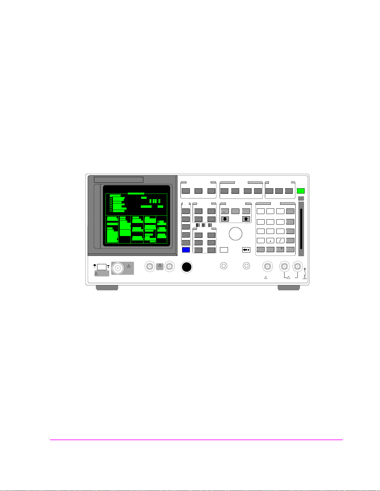
HP 8924C CDMA Mobile Station Test Set
User’s Guide
Firmware Version A.07.04 and above
!
POWER
DO NOT APPLY
RF WHEN OFF
RF IN/OUT
MAX PWR
CDMA CALL CONTRO L
CDMA SCRNS
CELL
CALL
CTRL
SPECTRUM
GEN
CTRL
ANALOG SCRNS
ENCODER
RF
ANL
AF
ANL
SPEC ANL
RF
GEN
END
CALL
RANGE
RX
TEST
MSRPT
TX
TEST
DECODER
RX
TEST
ACP
TX
TEST
SCOPE
DUPLEX
CALL ANS
USER DATA
k1’
k1
k2’
k2
k3’
k3
ASSIGN
k4
RELEASE
k5
!
6 W
MAX PWR
200 mW
!
FUNCTIONS
MSG
PRINTER
HELP
PRINT
DATA FUNCTIONS
REF SET
METER
INCR
INCR
: 10
SET
LO LIMIT HI LIMIT
CURSOR
CONTROL
CANCELSHIFT
I/O CONFIG CONFIG
PREV TESTS
AVG
INCR X10
PUSH TO
SELECT
ANTENNA INDUPLEX OUT
INSTRUMENT STATE
ADRS
SAVE
LOCAL
RECALL
789
456
123
+
0
ON/OFF
YES
Ω
NO
%
ppm
dBµV
W
AUDIO OUTSQUELCHVOLUMEMIC/ACC
MAX
!
12 v Pk
HOLD
MEAS
PRESET
RESET
MEMOR
Y CARD
ENTER
dB
GHz
dBm
%
MHz
V
s
kHz
_
mV
ms
Hz
µV
AUDIO IN
LOHI
MAX
!
42 v Pk
HP Part No. 08924-90038
Printed in U. S. A.
November 1999
Rev. F
1
Page 2

Copyright © Hewlett-Packard Company 1996
Notice Information contained in this document is subject to change without notice.
All Rights Reserved. Reproduct ion, adaptation, or translati on without prior written
permission is prohibited, except as allowed under the copyright laws.
This material may be reproduced by or for the U.S. Government pursuant to the
Copyright License under the clause at DFARS 52.227-7013 (APR 1988).
Hewlett-Packard Company
Learning Products Department
24001 E. Mission
Liberty Lake, WA 99019-9599
U.S.A.
2
Page 3

Manufacturer’s Declaration
This statement is provided to c omply with the req uiremen ts of t he German So und
Emission Directive, from 18 January 1991.
This product has a sound pressure emission (at the operator position) < 70 dB(A).
• Sound Pressure Lp < 70 dB(A).
• At Operator Position.
• Normal Operation.
• According to ISO 7779:1988/EN 27779:1991 (Type Test).
Herstellerbescheinigung
Diese Information steht im Zusammenhang mit den Anforderungen der
Maschinenlärminformationsverordnung vom 18 Januar 1991.
• Schalldruckpegel Lp < 70 dB(A).
• Am Arbeitsplatz.
• Normaler Betrieb.
• Nach ISO 7779:1988/EN 27779:1991 (Typprüfung).
3
Page 4

Safety
Considerations
GENERAL
This product and related document ation must be revi ewed for familiariz ation with
safety markings and instructions before operation.
This product has been designed and tested in accordance with IEC Publication
1010, "Safety Requirements for Electronic Measuring Apparatus," and has been
supplied in a s af e condition. This ins tr uction documentati on contains information
and warnings which must be followed by the user to ensure safe operation and to
maintain the product in a safe condition.
SAFETY EARTH GROUND
A uninterruptible safety earth ground must be provided from the main power
source to the product input wiring terminals, power cord, or supplied power cord
set.
CHASSIS GROUND TERMINAL
To prevent a potential shoc k hazard, always co nnect the rear-pa nel chassis gr ound
terminal to earth ground when operating this instrument from a dc power source.
SAFETY SYMBOLS
Indicates instrument damage can occur if indicated operating limits are exceeded.
!
Indicates hazardous voltages.
Indicates earth (ground) terminal
WARNING
A WARNING note denotes a hazard. It calls attention to a procedure,
practice, or the like, which, if not correctly performed or adhered to, could
result in personal injury. Do not proceed beyond a WARNING sign until the
indicated conditions are fully understood and met.
CAUTION
A CAUTION note denotes a hazard. It calls attention to an operation procedure,
practice, or the like, which, if not correctly performed or adhered to, cou ld resu lt
in damage to or destruction of part or all of the product. Do not proceed beyond
an CAUTION note until the indicated conditions are fully unde rstood and met.
4
Page 5

Safety Considerations for this Instrument
WARNING This product is a Safety Class I instrument (provided with a protective
earthing ground incorporated in the power cord). The mains plug shall only
be inserted in a socket outlet provided with a protective earth contact. Any
interruption of the protective conductor inside or outside of the p roduct is
likely to make the product dangerous. Intentional interruption is
prohibited..
Whenever it is likely that the protection has been impaired, the instrument
must be made inoperative and be secured against any unintended operation.
If this instrument is to be energized via an autotransformer (for voltage
reduction), make sure the common terminal is connected to the earth
terminal of the power source.
If this product is not used as specified, the protection provided by the
equipment could be impaired. This product must be used in a normal
condition (in which all means for protection are intact) only.
No operator serviceable parts in this product. Refer servicing to qualified
personnel. To prevent electrical shock, do not remove covers.
Servicing instructions are for use by qualified personnel only. To avoid
electrical shock, do not perform any servicing unless you are qualified to do
so.
The opening of covers or removal of parts is likely to expose dangerous
voltages. Disconnect the product from all voltage sources while it is being
opened.
Adjustmen ts describe d i n t h e ma nu al are perfor me d w i t h po w e r su p pl i e d t o
the instrument while protective covers are removed. Energy available at
many points may, if contacted, result in personal injury.
The power cord is connected to internal capacitors that my remain live for
5 seconds after disconnecting the plug from its power supply.
For Continued protection against fire hazard, replace the line fuse(s) only
with 250 V fuse(s) or the same current rating and type (for example, normal
blow or time delay). Do not use repaired fuses or short circuited
fuseholders.
5
Page 6

CAUTION: Always use the three-prong ac power cord supplied with this product. Failure to ensure
adequate earth grounding by not using this cord may cause product damage.
This product is designed for use in Installation Category II and Pollution Degree
2 per IEC 1010 and IEC 664 respectively.
This product has autorangi ng line voltage input, be sure the supply voltage is
within the specified range.
Ventilation Requirements: When installing the product in a cabinet, the
convection into and out of the product must not be restricted. The ambient
temperature (outside the cabinet) must be less than the maximum operating
temperature of the product by 4° C for every 100 watts dissipated in the cabinet.
If the total power dissipated in the cabin et is greater than 80 0 watts, then forced
convection must be used.
Product Markings CE - the CE mark is a registered trademark of the European Community. A CE
mark accompanied by a year indicated the year the design was proven.
CSA - the CSA mark is a registered trademark of the Canadian Standards
Association.
6
Page 7

CERTIFICATION Hewlett-Packard Company certifies that this product met its published specifica-
tions at the time of shipment from the factory. Hewlett-Packard further certifies
that its calibration measurements are traceable to the United States National In-
stitute of Standards and Technology, to the extent allowed by the Institute’s calibration facility, and to the calibration facilities of other International Standards
Organization members
WARRANTY This Hewlett-Packard instrument product is warra nted against defects in material
and workmanship for a period of one year from date of shipment. During the
warranty period, Hewlett-Packard Company will at its option, either repair or
replace products which prove to be defective.
For warranty service or repair, this product must be returned to a service facility
designated by HP. Buyer shall prepay shipping charges to HP and HP shall pay
shipping charges, duties, and taxes for products returned to HP from another
country.
HP warrants that its software and firmware designated by HP for use with an instrument will execute its programming instructions when properly installed on that
instrument. HP do es not warrant that the operation of the instrument, or software,
or firmware will be uninterrupted or error free.
LIMITATION OF
WARRANTY
EXCLUSIVE
REMEDIES
The foregoing warranty shall not apply to defects resulting from improper or
inadequat e maintenance by Buyer, Buyer-supplied soft ware or interfacing,
unauthorized modification or misuse, operation outside of the environmental
specifications for the product, or improper site preparation or maintenance.
NO OTHER WARRANTY IS EXPRESSED OR IMPLIED. HP SPECIFICALLY
DISCLAIMS THE IMPLIED WARRANTIES OF MERCHANTABILITY AND
FITNESS FOR A PARTICULAR PURPOSE.
THE REMEDIES PROVIDED HEREIN ARE BUYER’S SOLE AND
EXCLUSIVE REMEDIES. HP SHALL NOT BE LIABLE FOR ANY DIRECT,
INDIRECT, SPECIAL, INCIDENTAL, OR CONSEQUENTIAL DAMAGES,
WHETHER BASE ON CONTRACT, TORT, OR ANY OTHER LEGAL
THEORY.
ASSISTANCE Product maintenance agreements and other customer assistance agreements are
available for Hewlett -Packard products . For any assistance, contact your neares t
Hewlett-Packard Sales and Service Office.
7
Page 8
DECLARATION OF CONFORMITY
according to ISO/IEC Guide 22 and EN 45014
Manufacturer’s Name:
Manufacturer’s Address:
Hewlett-Packard Co.
Spokane Division
24001 E. Mission Avenue
Liberty Lake, Washington 99019-9599
USA
declares that the product
Product Name:
Model Number:
Product Options:
CDMA Mobile Station Test Set
HP 8924C
This declaration covers all options of the above
product.
conforms to the following Product specifications:
Safety: IEC 1010-1:1990+A1 / EN 61010-1:1993
EMC: CISPR 11:1990/EN 55011:1991- Group 1, Class A
EN 50082-1 : 1992
IEC 801-2:1991 - 4kV CD,8kV AD
IEC 801-3:1984 3V/m
IEC 801-4:1988 0.5 kV Sig. Lines, 1 kV Power Lines
Supplementary Information:
This product herewith complies with the requirements of the Low Voltage Directive
73/23/EEC and the EMC Directive 89/336/EEC and carries the CE-marking
accordingly.
Spokane, Washington USA October 17, 1996
Vince Roland
Reliability & Regulatory
Engineering Manager
European Contact: Your local Hewlett-Packard Sales and Service Office or Hewlett-Packard GmbH
Department ZQ/Standards Europe, Herrenberger Strasse 130, D-71034 Böblinger, Germany (FAX+49-7031-14-3143)
8
Page 9

HP 8924C Support
Contacts
The documentation suppl ied with your t est set is an exce llent source of re feren ce,
applications, and service information. Please use these manuals if you are experiencing technical problems:
• Applications information is included in the HP 8924C CDMA Mobile Station Test Set
Application Guide (HP P/N 08924-9002 1)
• Calibration and repair information are in the HP 8924C CDMA Mobile Station Test Set
Assembly Level Repair Manual - this manual (HP P/N 08924-90001).
If you have used the manuals and still have application questions, contact your
local HP Sales Representative.
Repair assistance is available for the HP 8924C CDMA Mobile Test Set from the factory
by phone and e-mail. Internal Hewlett-Packard users can contact the factory through
HPDesk or cc:Mail© (Lotus Corporation). Parts information is also available from
Hewlett-Packard.
When calling or writing for repair assistance, please have the fo llowing information
ready:
• Instrument model number (HP 8924C)
• Instrument Serial Number (tag located on the rear panel).
• Installed options - if any (tag located on the rear panel).
• Instrument firmware revision (displayed at the top of the screen when the Test Set is
powered up, and is also displayed on the CONFIGURE screen).
Support Telephone
Numbers:
1 800 827 3848 (Spokane Division Service Assistance, U.S. only)
1 509 921 3848 (Spokane Division Service Assistance, International)
1 800 227 8164 (HP Direct Parts Ordering, U.S. only)
1 916 783 0804 (HP Service Parts Identification, U.S. & Intl.)
Electronic mail (Internet): [email protected]
HP Desk: Spokane Service / HP1000/21
cc:Mail: SERVICE, SPOKANE /HP-Spokane,desk1
9
Page 10

Table 1 Regional Sales and Service Offices
United States of America
U.S. Instrument Support Center
For Test & Measurement Equipment
Repair & Calibration.
Hewlett-Packard Company
Englewood, Colorado 80112
Telephone: (800) 403-0801
Fax: (888) 857-8161
South Eastern E urope
Sales and Service
Hewlett-Packard Ges. m.b.h.
Liebigasse 1
P.O. Box 72
A-1222 Vienna, Austria
Telephone: 43 222 2500 0
Telex: 13 4425
Asia
Sales and Service
Hewlett-Packard Asia Ltd.
22-30/F Pere gri n e T ow e r
Lippo Center
89 Queensway, Central
Hong Kong
G.P.O. Box 863 Hong Kong
Telephone: 852-848-7777
Fax: 852-868-4997
United States of America
Customer Information Center
For Assistance On All HP
Products.
Hewlett-Packard Company
Tel: (800) 752-0900
6:00 am to 5:00 pm Pacific Time
Parts Direct: 1-800-227-8164
European Multicountry Region
Sales and Service
Hewlett-Packard S.A.
P.O. Box 95
150, Route dv Nant_dl_AVRIL
CH-1217 Meyrin 2
Geneva, Switzerland
Telephone: (41/22) 780-81 11
Fax: (41/22) 780-8542
Japan
Hewlett-Packard Japan, Ltd.
Measurement Assistance Center
9-1, Takakura-Cho
Hachioji-Shi
Tokyo 192-8510,
Japan
Telephone: (81)-426-56-7 832
Fax: (81)-426-56-7840
United Kingdom
Sales and Service
Hewlett-Packard Ltd.
Cain Road
Amen Corner
Bracknell, Berkshire
RG12 1HN
United Kingdom
Telephone: 44 344 360000
Fax: 44 344 363344
Northern Europe
Sales and Service
Hewlett-Packard Nederland B.V.
Startbaan 16
1187 XR
Amstelveen, The Netherlands
P.O. Box 667
Telephone: 31/20 5476911 X 6631
Fax: 31-20-6471825NL
International Sales Branch
Headquarters
Sales and Service
Hewlett-Packard S.A.
39 Rue Veyrot
P.O. Box 365
1217 Meyrin 1
Geneva, Switzerland
Telephone: 41-22-780-4111
Fax: 41-22-780-4770
Australia, New Zealand
Sales and Service
Hewlett-Packard Ltd.
P.O. Box 221
31-41 Joseph Street
Blackburn, Victoria 3130
Telephone: (61/3) 895-2895
Fax: (61/3) 898-9257
10
Canada
Sales and Service
Hewlett-Packard (Canada) Ltd.
5150 Spectrum Way
Mississauga, Ontario L4W 5G1
Canada
Telephone: (416) 206-4725
Fax: (416) 206-4739
Canada
Service Center
Hewlett-Packard Company
17500 Transcanada Highway
S. Serv Road
Kirkland, Quebec H9J 2X8
Canada
Telephone: (416) 206-3295
Page 11

Table 1 Regional Sales and Service Offices (Continued)
Canada
Service Center
Hewlett-Packard Ltd.
11120 178 Street
Edmonton, A lberta T5S 1P2
Canada
Telephone: (403) 486-6666
Fax: (403) 489-8764
Latin America
Hewlett-Packard Company
LAHQ Mexico City
Col. Lomas de Virreyes
11000 Mexico D.F.
Mexico
Telephone: (52/5) 326-4000
Fax: (52/5) 202 7718
11
Page 12

In this Book Throughout this manual the term "Test Set" is used to denote the HP 8924C.
Test Set screens sh own in thi s ma nual may not match those display ed on the Test
Set in every detail.
Chapter 1, Getting Started
This chapter provides basic remote and front-panel operating procedures, a quick check
for verifying operation, HP-IB programming procedures, and simple programming
examples.
Chapter 2, Configuring Your Test Set
This chapter provides information about setting screen inten sity , setting RF voltage
interpretation, setting time and date, and setting the beeper’s volume.
Chapter 3, Operating Overview
This chapter explains how to specify units of measure, how to use the analog meter,
how to use measurement averaging, how to set a measurement reference, how to set
measurement limits, how to enter and change values, how to save and recall instrument
setups, how to use the USER keys, and how to set a frequency offset. It also descri bes
some important interactions that occur between screen settings.
Chapter 4, Status Reporting
This chapter provides information about the Test Set’s status reporting structure and
status register groups.
Chapter 5, Remote Capabilities
This chapter describes the remote interface’s functions.
Chapter 6, Remote/Local Modes
This chapter describes the control annunciators, the effect of remote mode on frontpanel operation, the transitions from remote-to-local or local-to remote modes, and
how local lockout and clear lockout affect the Test Set’s operation.
Chapter 7, Memory Cards, Mass Storage
This chapter describes memory cards and mass storage devices used with the
Test Set.
Error Messages
This section discusses error and operating messages.
12
Page 13

Contents
1 Getting Started
Before Connecting a Radio 22
Accessing the Test Set’s Screens 23
Changing A Field’s Setting 26
Obtaining Measurement Results 30
Control Annunciators 35
Addressing 36
HP-IB Command Guidelines 37
Verifying th at the Test Set is Operating P roperly 42
13
S:\HP8924C\USRGUIDE\BOOK\24cug.TOC
Page 14

Contents
2 Configuring Your Test Set
General Operating Information 44
14
S:\HP8924C\USRGUIDE\BOOK\24cug.TOC
Page 15

Contents
3 Operating Overview
To Change the Measurement Display 49
To Enter and Change Values 58
Saving and Recalling Instrument Setups 61
Using USER Keys 65
Setting an RF Generator/Analyzer Frequency Offset 67
Setting an RF Generator/Analyzer Level Offset 68
Interaction Between Screens 69
Printing A Screen 71
Measurement Triggering Process 72
Triggering Analog Measurements In Local Mode (Front Panel
Operation) 76
Triggering CDMA Measurements In Local Mode (Front Panel
Operation) 79
Triggering Analog Measurements In Remote Mode (HP-IB
Operation) 82
Triggering CDMA Measurements In Remote Mode (HP-IB
Operation) 84
Increasing Measurement Throughput 86
Passing Instrument Control 94
15
S:\HP8924C\USRGUIDE\BOOK\24cug.TOC
Page 16

Contents
4 Status Reporting
Status Reporting 108
16
S:\HP8924C\USRGUIDE\BOOK\24cug.TOC
Page 17

Contents
5 Memory Cards/Mass Storage
Default File System 208
Mass Storage Device Overview 210
Default Mass Storage Locations 217
Mass Storage Access 219
DOS and LIF File System Considerations 220
Using the ROM Disk 225
Using Memory Cards 226
Backing Up Procedure and Library Files 232
Copying Files Using IBASIC Commands 233
Using RAM Disk 235
Using External Disk Drives 237
17
S:\HP8924C\USRGUIDE\BOOK\24cug.TOC
Page 18

Contents
6 IBASIC Controller
Introduction 240
The IBASIC Controller Screen 241
Important Notes for Program Development 243
Program Development 244
Interfacing to the IBASIC Controller using Serial Ports 246
Choosing Your Development Method 261
Method #1. Program Development on an External BASIC L anguage
Computer 263
Method #2. Developin g Programs on the Test Set Using t he IBASIC
EDIT Mode 270
Method #3. Developing Programs Using Word Processor on a PC
(Least Preferred) 274
Uploading Programs from the Test Set to a PC 281
Serial I/O from IBASIC Programs 282
PROGram Subsystem 285
The TESTS Subsystem 306
18
S:\HP8924C\USRGUIDE\BOOK\24cug.TOC
Page 19

Contents
Index 341
19
S:\HP8924C\USRGUIDE\BOOK\24cug.TOC
Page 20

Contents
20
S:\HP8924C\USRGUIDE\BOOK\24cug.TOC
Page 21

1 Getting Started
This chapte r will help fami liarize you with fundamen tal Test Set operation,
including:
• Accessing screens and fields
• Making a simple measurement
• Preparation for remote operation via HP-IB
21
S:\HP8924C\USRGUIDE\BOOK\chapters\getstart.fb
Page 22

Chapter 1, Getting Started
Before Connecting a Radio
Before Connecting a Radio
NOTE: The RF IN/OUT port should be used for all transmitter tests when the radio is co nnected
directly to the Test Set. (All MSUT (Mobile Station Under Test) transmitter power
measurements are made through this port). Off-the-air measurements can be made using the
highly-sensitive ANT IN port.
CAUTION: Overpower Damage — Refer to the Test Set’s front panel for maximum input power level.
Exceeding this level can cause permanent instrument damage.
Overpower Damage — Blocking the fans’s rotation or operating the Test Set in
an environment that causes excessive heat may cause damage.
Important: If excessive temperatures are sensed on the power supply regulator
assembly, the Test Set’s power supply will shut off. After temperature has
lowered to within normal operating range, use the POWER switch to cycle power
on. Remove RF power from the RF IN/OUT connector whenever the Test Set is
off.
22
S:\HP8924C\USRGUIDE\BOOK\chapters\getstart.fb
Page 23

Accessing the Test Set’s Screens
Accessing the Test Set’s Screens
CDMA and Analog Modes
The Test Set has two operating modes, analog and CDMA. In CDMA mode, the
Test Set configures its elf as a cali brate d CDMA base stati on. In Anal og mode, the
Test Set has AMPS, NAMPS and TACS analog cellular phone test capability.
CDMA is the default power-up mode. To enter analog mode from CDMA mode:
• press one of the ANLG SCRNS keys, or
• select a screen from the Analog To Screen menu, or
• programmatically select an analog screen using the display (DISP) HP-IB subsystem,
or
• execute a CDMA to Analog handoff.
To enter CDMA mode from analog mode:
Chapter 1, Getting Started
• press one of the CDMA SCRNS keys, or
• select a screen from the CDMA To Screen menu, or
• programmatically select a CDMA screen using the display (DISP) HP-IB subsystem.
23
S:\HP8924C\USRGUIDE\BOOK\chapters\getstart.fb
Page 24
Chapter 1, Getting Started
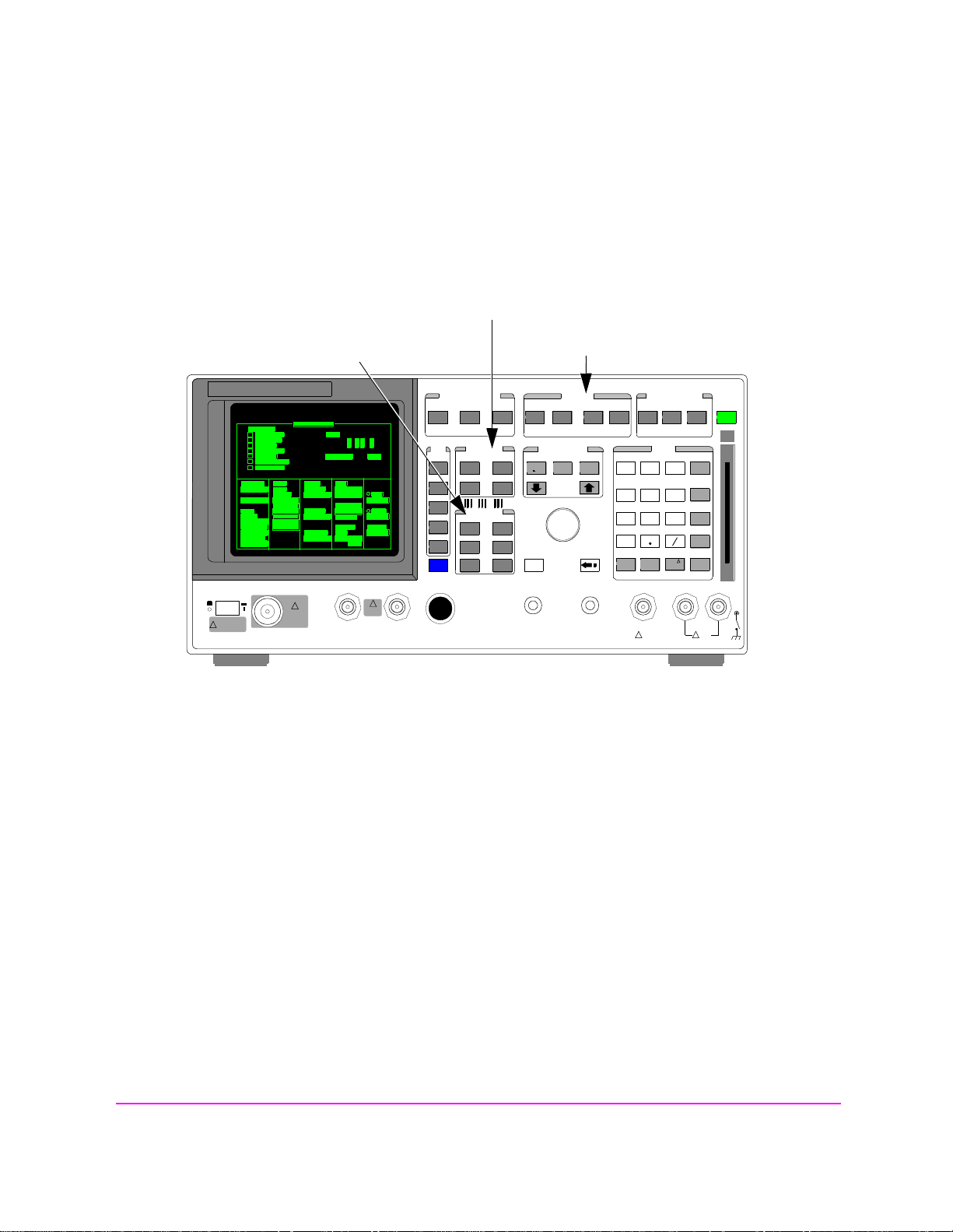
Functions Screens
Accessing the Test Set’s Screens
Screens that control various instrument functions such as configuration, access to
the Tests subsystem, and the PREV (previous screen) key are found under the
front-panel “Functions” bracket.
CDMA Digital Transceiver Measurements
Analog Transceiver Tests
!
POWER
DO NOT APPLY
RF WHEN OFF
RF IN/OUT
MAX PWR
!
6 W
DUPLEX OUT
MAX PWR
200 mW
!
ANTENNA IN
Figure 1 Accessing Test Set Screens
Instrument Functi ons
CDMA CALL CONTRO L
CDMA SCRNS
CELL
CALL
CTRL
SPECTRUM
GEN
CTRL
ANALOG SCRNS
ENCODER
RF
ANL
AF
ANL
SPEC ANL
RF
GEN
END
CALL
RANGE
RX
TEST
MSRPT
TX
TEST
DECODER
RX
TEST
ACP
TX
TEST
SCOPE
DUPLEX
CALL ANS
USER DATA
k1’
k1
k2’
k2
k3’
k3
ASSIGN
k4
RELEASE
k5
FUNCTIONS
MSG
PRINTER
HELP
PRINT
DATA FUNCTIONS
REF SET
METER
INCR
INCR
: 10
SET
LO LIMIT HI LIMIT
CURSOR
CONTROL
CANCELSH IFT
I/O CONFIG CONFIG
PREV TESTS
AVG
INCR X10
PUSH TO
SELECT
INSTRUMENT STATE
ADRS
LOCAL
789
456
123
0
NO
YES
ppm
ON/OFF
W
AUDIO OUTSQUELCHVOLUMEMIC/ACC
MAX
!
12 v Pk
SAVE
RECALL
HOLD
MEAS
PRESET
RESET
MEMOR
Y CARD
ENTER
dB
GHz
dBm
%
MHz
V
s
kHz
_
+
mV
ms
Ω
Hz
%
µV
dBµV
AUDIO IN
LOHI
MAX
!
42 v Pk
24
S:\HP8924C\USRGUIDE\BOOK\chapters\getstart.fb
Page 25

Accessing the Test Set’s Screens
Cursor Control
Chapter 1, Getting Started
INSTRUMENT STATE
ADRS
SAVE
LOCAL
RECALL
789
456
123
+
0
YES
NO
ppm
ON/OFF
dBµV
W
AUDIO OUTSQUELCHVOLUMEMIC/ACC
MAX
!
12 v Pk
HOLD
MEAS
PRESET
RESET
MEMOR
Y CARD
ENTER
dB
GHz
dBm
%
MHz
V
s
kHz
_
mV
ms
Ω
Hz
%
µV
AUDIO IN
LOHI
MAX
!
42 v Pk
1
2
MAX PWR
200 mW
!
ANTENNA IN
CDMA CALL CON TROL
CDMA SCRNS
CELL
CALL
CTRL
SPECTRUM
GEN
CTRL
CDMA SCRNS
ENCODER
RF
ANL
AF
ANL
SPEC ANL
RF
GEN
END
CALL
RANGE
RX
TEST
MSRPT
TX
TEST
DECODER
RX
TEST
ACP
TX
TEST
SCOPE
DUPLEX
CALL ANS
USER DATA
k1’
k1
k2’
k2
k3’
k3
ASSIGN
k4
RELEASE
k5
FUNCTIONS
MSG
PRINTER
HELP
PRINT
DATA FUNCTIONS
REF SET
METER
INCR
INCR
: 10
SET
LO LIMIT HI LIMIT
CURSOR
CONTROL
CANCELSHIFT
I/O CONFIG CONFIG
PREV TESTS
AVG
INCR X10
PUSH TO
SELECT
1. Position
To position the cursor, rotate the Cursor Control knob, which moves the cursor from
field to field or from menu item to menu item. Normally the cursor appears as a small
highlighted rectangular box.
2. Select
To select an item, push the Cursor Co ntrol knob . After selection, the background of t he
item selected becomes highlighted or the item selected appears in an associated field.
25
S:\HP8924C\USRGUIDE\BOOK\chapters\getstart.fb
Page 26
Chapter 1, Getting Started
Changing A Field’s Setting
Changing A Field’s Setting
There are several types of CRT display fields in the Test Set. This section
describes some of the different types of fields, and how they are used.
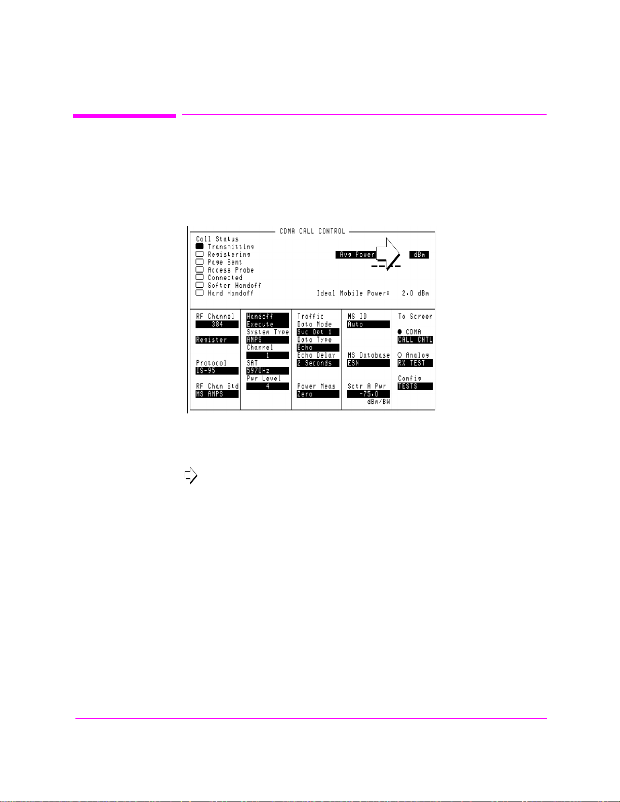
Units-of-Measure Field
Figure 2 Units-of-Measure Field
Units-of-measure fields allow selection of valid units for given measurement. See
figure 2 to see an example of a units-of-measure field.
in
To change a unit-of-measure
1. Position the cursor at the unit field on the display.
2. Press a key labeled with a different unit-of-measure (such as W).
3. If the new units are valid, the measurement value will be displayed in the new unit-of-
measure.
To change the unit s- of- measure for data tra nsf er vi a HP- IB, s ee "To Specify Units-
of-Measure for HP-IB Data Transfer" in chapter 3
.
26
S:\HP8924C\USRGUIDE\BOOK\chapters\getstart.fb
Page 27
Changing A Field’s Setting
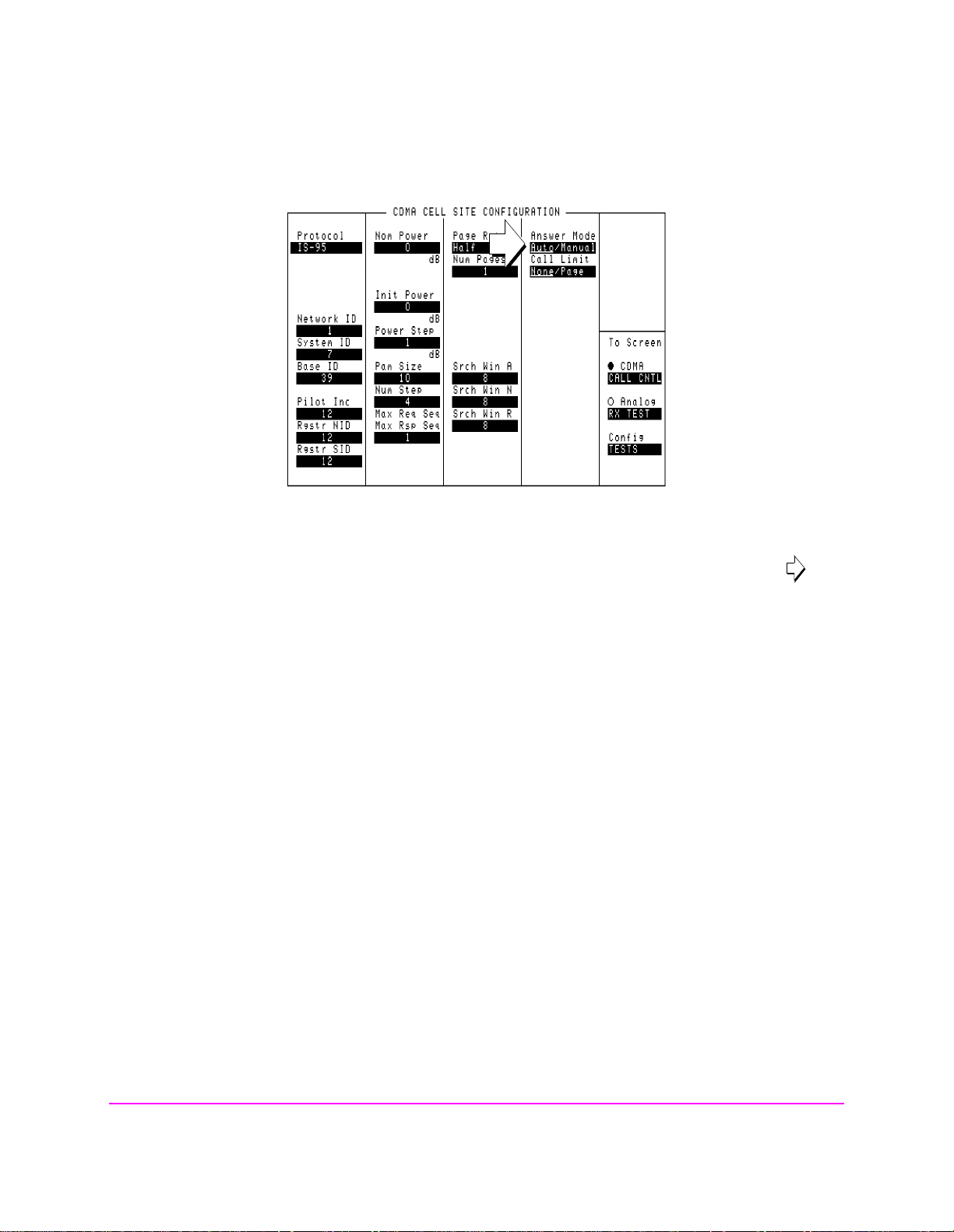
Underlined Immediate-Action Field
Chapter 1, Getting Started
Figure 3 Underlined Immediate-Action Field
Underlined immediate action fields provide a choice of two settings. See in
figure 3 to see an example of an underlined immediate-action field.
To change an underlined entry
1. Position the cursor at the field.
2. Push the CURSOR CONTROL knob or the ENTER key to underline the desired
choice.
27
S:\HP8924C\USRGUIDE\BOOK\chapters\getstart.fb
Page 28
Chapter 1, Getting Started
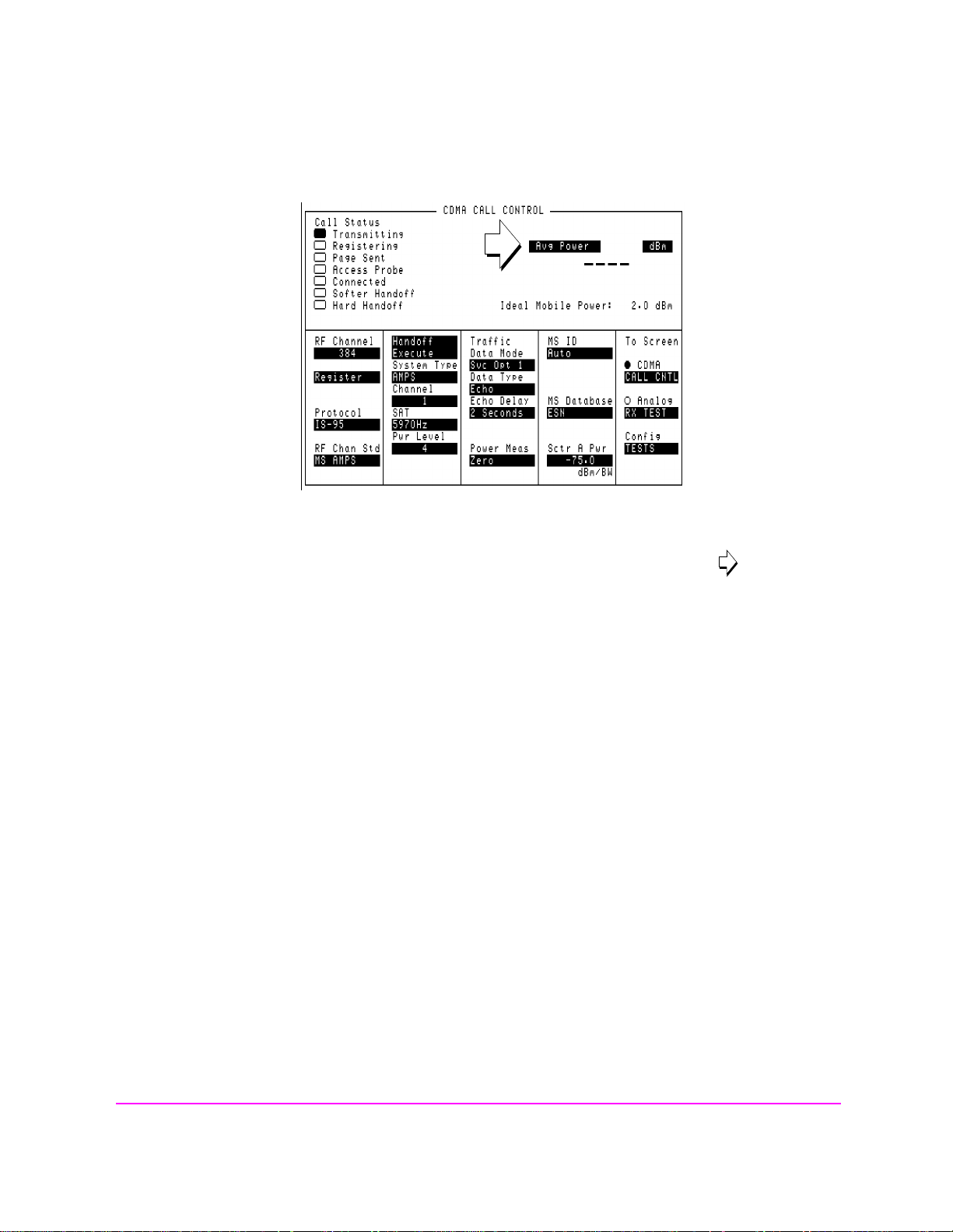
One-of-Many Field
Changing A Field’s Setting
Figure 4 One-of-Many Field
One-of-many fields displ ay a list of ch oic es when select ed. See in figure 4 to
see an example of a one-of many field.
To make a one-of-many choice
1. Position the cursor at the field.
2. Push the C
3. Move the cursor through the choices by turning the knob.
4. Push the C
URSOR CONTROL knob or the ENTER key to display the choices.
URSOR CONTROL knob or the ENTER key to make the choice.
28
S:\HP8924C\USRGUIDE\BOOK\chapters\getstart.fb
Page 29
Changing A Field’s Setting
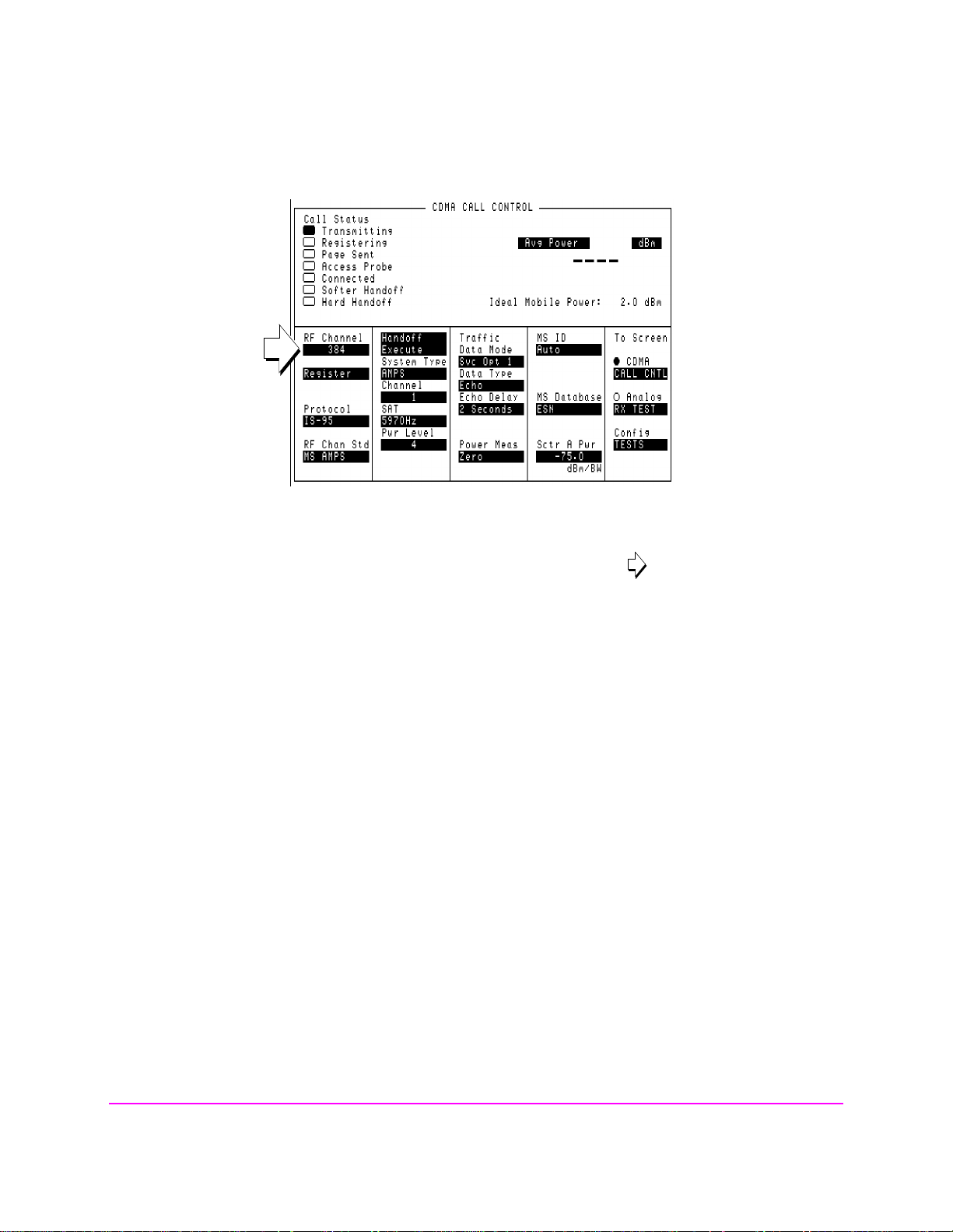
Numeric-Entry Field
Chapter 1, Getting Started
Figure 5 Numeric-Entry Field
Numeric-entry fields contain numeric values. See in figure 5 to see an
example of a numeric-entry field.
To change a value
1. Position the cursor at the field.
2. Key in the desired number using the DATA keys.
3. Press ENTER to select the choice.
OR
1. Position the cursor at the field.
2. Push the C
3. Turn the knob to increment or decrement the value.
4. Push the C
URSOR CONTROL knob to highlight the desired choice.
URSOR CONTROL knob or the ENTER key to select the choice.
29
S:\HP8924C\USRGUIDE\BOOK\chapters\getstart.fb
Page 30

Chapter 1, Getting Started
Obtaining Measurement Results
Obtaining Measurement Results
Setting Up a Call
To obtain CDMA measurements, the Test Set must have the MSUT (Mobile
Station Under Test) on a call (the Connected annunciator on the CDMA CALL
CONTROL screen is lit when the MSUT is on a call).
The procedure for setting up a call is provided in “Setting Up a Call”, found in the HP
8924C Application Guide
procedures for performing CDMA tests.
Triggering and Displaying Measurements
When operated over the front panel (lo cal control), Test Set measurement results
are obtained by selecting a screen that displays the desired measurement, arming
the measurement if necessary, and observing the displayed value.
. In the HP 8924C Application Guide, there are also
When operated remotely, measurement results are obtained via HP-IB by
triggering a measurement if necessary and querying the desired measurement
field.
NOTE: In CDMA mode, transmitter (TX) measu rements and rec eiver (RX) measur ements c an
run concurrently. For example, an Average Power or Channel Power measurement
can be queried while the RX TEST screen is selected and an FER measurement is
running.
For a detailed description of triggering measurements, see
Displaying Measurements" on page 30
.
"Triggering and
30
S:\HP8924C\USRGUIDE\BOOK\chapters\getstart.fb
Page 31

Obtaining Measurement Results
Preparing the Test Set for HP-IB Control
1. If other HP-IB devices are in the system, attach an HP-IB cable from the Test Set’s rear-
panel HP-IB connector to any one of the other devices in the test system.
2. Access the I/O CONFIGURE screen and perform the following steps:
a. Set the Test Set’s HP-IB address using the HP-IB Adrs field (see "Addressing"
on page 36).
b. Set the Test Set’s HP-IB Controller capabilit y using the Mode field.
• Talk&Listen configures the Test S et to be controlled through HP-IB with an
external controller. The Test Set has Active Controller capability (take control/
pass control) in this mode.
• Control configures the Test Set to be the system controller. Use this setting
if the Test Set will be the only controller on the HP-IB. Selecting Control
automatically makes the Test Set the active controller.
NOTE: Only one active controller is allowed on the HP-IB at one time!
Chapter 1, Getting Started
3. If an HP-IB printer is or will be connected to the Test Set’s rear-panel HP-IB connector,
perform the following steps:
a. Access the PRINT CONFIGURE screen.
b. Select one of the supported HP-IB printer models using the Model field.
c. Set the Printer Port field to HP-IB.
d. Set the printer address using the Printer Address field.
31
S:\HP8924C\USRGUIDE\BOOK\chapters\getstart.fb
Page 32

Chapter 1, Getting Started
Obtaining Measurement Results
General Programming Procedure
1. For each measurement you want to perform programmatically, make the measuremen t
manually using the front-panel controls of the Test Set. You will find procedures for
making measurements in the HP 8924C Application Guide. Record, in sequential order,
the screens selected and the settings made within each screen.
2. Record the measurement result(s).
3. Develop the program using the measurement procedure generated in step 2. For CDMA
measurements, the HP 8924C Application Guide provides step-by-step HP-IB
command examples.
4. Make sure the desired measurement is selected and in the ON state. This is the PRESET
state for most measurements. However, if a previous program has set the state to OFF,
no measurement result will be available. Attempting to read from a measurement field
that is not in the ON state will cause HP-IB Error:-420 Query
UNTERMINATED.
5. Trigger the desired measurement if the RETRigger MODE is SINGle. You will find
that the Test Set automatically enters REPetitive trigger MODE for CDMA
measurements when an HP-IB command is sent to it.
6. Send the appropriate MEASure query command to initiate a reading. This will place the
measured value into the Test Set’s Output Queue.
7. Use the ENTER stat ement to transfer the measured value to a variable within the
context of the program.
32
S:\HP8924C\USRGUIDE\BOOK\chapters\getstart.fb
Page 33

Obtaining Measurement Results
Basic Programming Examples
The following examples illustrate the basic approach to controlling the Test Set
through the HP-IB. The punctuation and command syntax used for these
examples is given in
The bus address 714 used in the fol lowing BASI C languag e exam ples us es an HPIB interface at select code 7, and a Test Set HP-I B address o f 14. All examples use
an external controller.
To Change a Field’s Setting
1. Access the screen containing the field whose setting is to be changed by using the DISP
command.
2. Make the desired setting using the proper command syntax (refer to
“HP-IB Comma nd Syntax” chapter in the HP 8924C Condensed Programming
Reference Guide for proper syntax).
The following example makes several instrument setting changes:
Chapter 1, Getting Started
"Command Punctuation" on page 38.
OUTPUT 714;”DISP CCNT”!Displays the CDMA CALL CONTROL screen.
OUTPUT 714;”CDMA:CELL:ASEC -100”!Sets Sector A Power to -100 dBm/BW.
OUTPUT 714;”RFG:OUTP ’DUPL’”!Sets the Output Port to Duplex.
To Read a Field ’s Setting
1. Access the screen containing the field whose setting is to be read using the DISPlay
command.
2. Use the query form of the syntax for that field to place the setting’s value into the Test
Set’s output buffer.
3. Enter the value into the correct variable type within the program’s context.
The following example reads the current power measurement selection (Average
Power or Channel Power).
10 OUTPUT 714;”DISP CTXT” !Displays the CDMA CELLULAR MOBILE TRANSMITTER TEST screen.
20 OUTPUT 714;”CDMA:TX:POW:MEAS?” !Queries the Average Power/Channel Power field.
30 ENTER 714;Pow$ !Enters the returned value into a string variable
40 PRINT “The power measurement currently selected is “,Pow$
50 END
33
S:\HP8924C\USRGUIDE\BOOK\chapters\getstart.fb
Page 34

Chapter 1, Getting Started
Obtaining Measurement Results
To Make a Simple Measurement
1. Access the screen containing the desired measurement by using the DISP command.
2. Use the MEAS form of the syntax for that measurement to place the measured value
into the Test Set’s output buffer.
3. Enter the value into the correct variable type within the program’s context (refer to the
”Number Measurement Syntax” in HP-IB Command Syntax chapter of th e HP 8924C
Condensed Programming Reference Guide for the proper variable type).
NOTE: Whenever a numeric value is queried, the returned value is always in HP-IB Units. Refer to
"To Specify Units-of-Measure for HP-IB Data Transfer" on page 56.
The following example program illustrates how to make settings and then take a
reading from the Test Set. This setup takes a reading from the analog spectrum
analyzer’s marker after tuning it to the RF generator output frequency.
10 Addr=714
20 OUTPUT Addr;”*RST”! Preset to known state
25 OUPTUT Addr;”CONF:OFR 0” !Set the RF frequency offset to 0 MHz.
30 OUTPUT Addr;”TRIG:MODE:RETR SING”! Sets single trigger
40 OUTPUT Addr;”DISP RFG”! Selects the RF GENERATOR screen
50 OUTPUT Addr;”AFG1:FM:STAT OFF”! Turns FM OFF
60 OUTPUT Addr;”RFG:AMPL -66 DBM”! Sets RF Gen amplitude to -66 dBm
70 OUTPUT Addr;”RFG:FREQ 500 MHZ”! Sets RF Gen frequency to 500 MHz
80 OUTPUT Addr;”RFG:AMPL:STAT ON”! Turns RF Gen output ON
90 OUTPUT Addr;”DISP SAN”! Selects SPECTRUM ANALYZER screen
100 OUTPUT Addr;”SAN:CRF 500 MHZ”! Center Frequency 500 MHz
110 ! -------------------MEASUREMENT SEQUENCE-------------------120 OUTPUT Addr;”TRIG”! Triggers reading
130 OUTPUT Addr;”MEAS:SAN:MARK:LEV?”! Query of Spec Anl marker level
140 ENTER Addr;Lvl! Places measured value in variable Lvl
150 DISP Lvl! Displays value of Lvl
160 END
The above example is very simple and is des igned to demonstrat e the fundamental
procedure for obtaining a measurement result. Many other factors must be
considered when designing a measurement proce dure, such as instru ment settings,
signal routing, settling time, filtering, triggering and measurement speed.
34
S:\HP8924C\USRGUIDE\BOOK\chapters\getstart.fb
Page 35

Control Annunciators
Control Annunciators
The letters and symbols at the top right corner of the display indicate these conditions:
R indicates the Test Set is in remote mode. The Test Set can be put into the remote mode
by an external controller or by an IBASIC program running on the built-in IBASIC controller.
• L indicates the Test Set has been addressed to listen.
• T indicates the Test Set has been addressed to talk.
• S indicates the Test Set has sent the require service message by setting the service re-
quest (SRQ) bus line true. (See "Status Reporting" on page 108).
• C indicates the Test Set is currently the active controller on the bus.
• * indicates an IBASIC program is running.
Chapter 1, Getting Started
• ? indicates an IBASIC program is waiting for a user response.
• - indicates an IBASIC program is paused.
35
S:\HP8924C\USRGUIDE\BOOK\chapters\getstart.fb
Page 36

Chapter 1, Getting Started
Addressing
Addressing
Setting the Test Set Bus Address
The Test Set’s HP-IB bus address is set using the HP-IB Adrs field which is
located on the I/O CONFIGURE screen. The Test Set’s HP-IB address is set to
decimal 14 at the factory. To set a different HP-IB bus address; select the I/O
CONFIGURE screen and position the cursor next to the
address can be set from decimal 0 to 30 using the numeric DATA keys, or by
pushing and then rotating the CURSOR CONTROL knob. There are no switches
for setting the HP-IB bus address in the Test Set. The new setting is retained when
the Test Set is turned off.
Displaying the Bus Address
HP-IB Adrs field. The
The Test Set’s HP-IB bus address can be displayed by pressing and releasing the
SHIFT key, then the LOCAL key. The address is displayed in the upper-left
corner of the display.
36
S:\HP8924C\USRGUIDE\BOOK\chapters\getstart.fb
Page 37

HP-IB Command Guidelines
HP-IB Command Guidelines
Command Names
HP-IB commands are not case sensitive. Upper and lower case characters can be
used for all commands.
For example, to set the destination of AF Generator 1 to Audio Out, any of the
following command strings are valid:
“AFGENERATOR1:DESTINATION ’AUDIO OUT’”
or
“afgenerator1:destination ’audio out’”
or
“afg1:dest ’audio out’”
or
“AFG1:DEST ’AUDIO OUT’”
or
“Afg1:Dest ’Audio oUT’”
Chapter 1, Getting Started
All command names of more than four characters have an alternate abbreviated
form. The abbreviated form is presented in uppercase letters in the syntax
diagrams.
37
S:\HP8924C\USRGUIDE\BOOK\chapters\getstart.fb
Page 38

Chapter 1, Getting Started
HP-IB Command Guidelines
Command Punctuation
NOTE: Programming La nguage Consideratio ns: The punctuation rules for the Test Set’s HP-IB
commands conform to the IEEE 488.2 standard. It is possible that some programming
languages used on external controllers may not accept some of the punctuation requirements.
It is therefore necessary that the equivalent form of the correct punctuation, as defined by the
language, be used for HP-IB operation. Improper punctuation will result in HP-IB Error:
-102 Syntax Error.
Using Quotes for String Entries
Quotation marks are used to select non-numeric field settings. The value is
entered into the command line as a quoted alphanumeric string.
Quotes are used with all underlined
fields. (See
"To Change a Field’s Setting" on page 33.)
For example: to set the RF Generator’s
choice
“RFG:OUTP ’Dupl’”
Using Spaces
Dupl would be entered into the command string.
(toggling) and one-of-many (menu choice)
Output Port field to duplex, the menu
When changing a field’s setting, a space must always precede the setting value in
the command string, regardless of the field type.
space
space
850MHZ
’OFF’
RFG:FREQ
RFG:ATT
Using Colons to Separate Comma nds
The HP-IB command syntax is structured using a control hierarchy that is
analogous to manual operation.
The control hierarchy for making a manual instrument setting using the frontpanel controls is as follows: first the s creen is accessed, then the desired field +is
selected, then the appropriate setting is made. HP-IB commands use the same
hierarchy. The colon (:) is used to separate the different levels of the command
hierarchy.
For example: To set the AF Analyzer’s input gain to 40 dB, the following
command syntax would be used:
“DISP AFAN”
“AFAN:INP:GAIN ’40 dB’”
38
S:\HP8924C\USRGUIDE\BOOK\chapters\getstart.fb
Page 39

HP-IB Command Guidelines
Using the Semicolon to Output Multiple Commands
Multiple commands can be output from one program line by separating the
commands with a semicolon (;). The semic olon tells the Test Set’s HP- IB
command parser to back up one level of hierarchy and accept the next command
at the same level as the previous command.
For example, on one command line, it is possible to:
1. access the AF ANALYZER screen,
2. set the AF analyzer’s input to AM Demod
3. set Filter 1 to 300 Hz HPF
4. set Filter 2 to 3kHz LPF
“DISP AFAN;AFAN:INP ’AM DEMOD’;FILT1 ’300Hz HPF’;FILT2 ’3kHz LPF’”
The semicolon after the “DISP AFAN” command tells the Test Set’s HP-IB
command pa rser that the next command is at the same level in the command
hierarchy as the display command. Similarly, the semicolon after the INP ’AM
DEMOD’ command tells the command parser that the next command (FILT1
’300Hz HPF’) is at the same command level as the INP ’AM DEMOD’
command.
Chapter 1, Getting Started
Using the Semicolon Colon (;:) to Separate Commands
A semicolon followed by a colon (; :) tells th e HP-IB command parser th at the next
command is at the top level o f the comman d hierarc hy. This allows comman ds for
different instruments to be output on one command line. The following example
sets the RF Analyzer’s tune frequency to 850 MHz, and then sets the AF
Analyzer’s input to FM Demod.
“RFAN:FREQ 850 MHZ;:AFAN:INP ’FM DEMOD’”
39
S:\HP8924C\USRGUIDE\BOOK\chapters\getstart.fb
Page 40

Chapter 1, Getting Started
HP-IB Command Guidelines
Using Question Marks to Query Setting or Measurement Fields
The question mark (?) is used to query (read-back) an instrument setting or
measurement value. To generat e the query for m of a command, place t he question
mark immediately after the command. Queried information must be read into the
proper variable type w i thin the program context before it can be displayed,
printed, or used as a numeric value in the program.
Queried informati on is r eturne d in the same f ormat u sed to se t the value ( a querie d
numeric field returns numeric data; quoted string fields return quoted string
information).
For example, the following BASIC language program statements query the
current setting of the
OUTPUT 714;”AFG1:DEST?”!Query the AFGen1 To field.
ENTER 714;Afg1_to$!Enter queried value into a string variable
Sample HP-IB Program
AFGen 1 To field:
The following program was written on an HP 9000 Series 300 controller using
Hewlett-Packard Rocky Mountai n BASIC (RMB). To run this program d irectly in
the Test Set’s IBASIC Controller:
1. use exclamation marks (!) to comment-out lines 440, 450, and 460 (these commands
not supported in IBASIC).
2. change line 70 to Bus = 8 (internal HP-IB select code = 8).
40
S:\HP8924C\USRGUIDE\BOOK\chapters\getstart.fb
Page 41

Chapter 1, Getting Started
HP-IB Command Guidelines
10 ! This program generates an FM carrier, measures and displays the
20 ! deviation, and draws the modulation waveform from the oscilloscope
30 ! to the CRT display. For demonstration purposes the
40 ! carrier is generated and analyzed through the uncalibrated input
50 ! path so that no external cables are required.
60 GCLEAR! Clear graphics display.
70 Bus=7! Interface select code of HP-IB interface
80 Dut=100*Bus+14! Default Test Set HP-IB address is 14
90 CLEAR Bus ! Good practice to clear the bus
100 CLEAR SCREEN ! Clear the CRT
110 OUTPUT Dut;”*RST” ! Preset the Test Set
120 OUTPUT Dut;”DISP DUPL” ! Display the DUPLEX TEST screen
130 OUTPUT Dut;”RFG:AMPL -14 DBM”! Set RF Gen Amplitude to -14 dBm
140 OUTPUT Dut;”AFAN:INP ’FM Demod’” ! Set AF Analyzer input to FM Demod
150 OUTPUT Dut;”AFAN:DET ’Pk+-Max’” ! Set AF Analyzer detector to Peak +/-Max
160 !
170 ! The following trigger guarantees that the instrument will auto-tune and
180 ! auto-range to the input signal before measuring.
190 !
200 OUTPUT Dut;”TRIG” ! Trigger all active measurements
210 OUTPUT Dut;”MEAS:AFR:FM?” ! Request an FM deviation measurement
220 ENTER Dut;Dev ! Read measured value into variable Dev
230 PRINT USING “K,D.DDD,K”;”Measured FM = “,Dev/1000,” kHz peak.”
240 DISP “’Continue’ when ready...” ! Set up user prompt
250 ON KEY 1 LABEL “Continue”,15 GOTO Proceed ! Set up interrupt on softkey 1
260 LOOP ! Loop until the key is pressed
270 END LOOP
280 Proceed: OFF KEY ! Turn off interrupt from softkey 1
290 DISP “” ! Clear the user prompt
300 !
310 ! Measure and plot an oscilloscope trace to see the waveform shape.
320 DIM Trace(0:416) ! Oscilloscope has 417 trace points
330 OUTPUT Dut;”DISP OSC” ! Display the OSCILLOSCOPE screen
340 OUTPUT Dut;”TRIG” ! Trigger all active measurements
350 OUTPUT Dut;”MEAS:OSC:TRAC?” ! Request the oscilloscope trace
360 ENTER Dut;Trace(*) ! Read the oscilloscope trace into array Trace(*)
370 !
380 ! CRT is (X,Y)=(0,0) in lower left corner to (399,179) upper right.
390 ! (Each pixel is about 0.02 mm wide by 0.03 mm tall, not square.)
400 ! Scale vertically for 0 kHz dev center-screen and +4 kHz dev top
410 ! of screen. Leave the next three lines for external control, or
420 ! comment them out for IBASIC (Test Set stand-alone) control.
430 !
440 PLOTTER IS CRT,”98627A” !Your display may have a different specifier.
450 GRAPHICS ON!Enable graphics to plot the waveform.
460 WINDOW 0,399,0,179
470 !
480 PEN 1 !Turn on drawing pen
490 MOVE 0,89.5+Trace(0)/4000*89.5
500 FOR I=1 TO 416
510 DRAW I/416*399,89.5+Trace(I)/4000*89.5
520 NEXT I
530 END
41
S:\HP8924C\USRGUIDE\BOOK\chapters\getstart.fb
Page 42

Chapter 1, Getting Started
Verifying that the Test Set is Operating Properly
Verifying that the Test Set is Operating Properly
If your Test Set powers-up and displays the CDMA CALL CONTROL screen,
but you suspect an instrument problem, the CDMA Mode Quick Check will ve rify
operation of the instrument’s basic functions.
CDMA Mode Quick Check
NOTE: This procedure assumes that the Test Set is con figured for cellular mobile station testin g. If
necessary, access the CONFIGURE screen and turn PCS Intrfc Control Off
necessary to cycle power.
1. Remove any cabling from the front-panel connectors.
2. Turn instrument power on (if it is not already on).
3. Press the PRESET key.
. It will then be
4. Press and release the SHIFT key then the TESTS key to access the CONFIGURE
screen.
5. Position the cursor in the RF Display field, and press the knob to select Freq. The
RF Offset and (Gen)-(Anl)fields will appear below RF Display.
6. Change the (Gen)-(Anl) value to 0 MHz.
7. Position the cursor in the Output Port field and Select Dupl
8. Press GEN CTRL, +/-, 5, 0 ENTER to adjust Sector A Power to -50 dBm/BW.
9. Press and release the SHIFT key then the GEN CTRL key to access the CDMA
REVERSE CHANNEL SPECTRUM analyzer screen.
10. Position the cursor in the Ref Level field, and press +/-, 1, 0, ENTER to enter a
reference level of -10 dBm.
11. The display should show a CDMA signal, approximately 1.23 MHz wide.
.
If no failure is indicated by this test, but you still suspect a problem, refer to the
performance tests information in the HP 8924C Assembly Level Repair Manual.
42
S:\HP8924C\USRGUIDE\BOOK\chapters\getstart.fb
Page 43

2 Configuring Your Test Set
This chapter will he lp you prepa re th e Test Set f or ope rati on in your envi ronment.
This includ es:
• Setting screen intensity
• Setting time and date
• Setting beeper volume
43
S:\HP8924C\USRGUIDE\BOOK\chapters\configts.fb
Page 44

Chapter 2, Configuring Your Test Set
General Operating Information
General Operating Information
The following configuration information discusses general operating information
for some of the fields in the CONFIGURE screen.
To Set Screen Intensity
1. Access the CONFIGURE screen.
2. Select the Intensity field.
3. Rotate the knob to change the setting (1=dim, 8=brigh t).
To Set RF Voltage Interpretation (50 ohm/emf)
1. Access the CONFIGURE screen.
2. Position the cursor in front of the RFGen Volts field.
3. Press the CURSOR CONTROL knob or press the ENTER key to select 50 ohm
.
emf
Voltage settings can control either:
• the voltage across a 50-ohm load, or
• the open circuit voltage (emf).
This setting affects the RF Generator and Tracking Generator amplitudes.
or
44
S:\HP8924C\USRGUIDE\BOOK\chapters\configts.fb
Page 45

General Operating Information
To Set the Date and Time
1. Access the CONFIGURE screen.
2. Select the Date field and use the DATA keys to enter the date in the format shown
below the field.
3. Select the Time field and use the DATA keys to enter the time in the format shown
below the field.
The Test Set has a built-in clock that keeps track of the date and time. It is
powered by an internal battery to keep it operating when the instrument is off.
To Change the Beeper’s Volume
1. Access the CONFIGURE screen.
2. Select the Beeper field to display the volume choices.
3. Select the desired choice.
The beeper alerts you to important operating and measurement conditions. It
beeps any time a message is displayed at the top of the screen. These messages
warn you of conditio ns such as ex ceedin g the RF input level or t rying to set a f ield
to an unacceptable value. The refore, it is rec ommended that you do no t disabl e the
beeper.
Chapter 2, Configuring Your Test Set
45
S:\HP8924C\USRGUIDE\BOOK\chapters\configts.fb
Page 46

Chapter 2, Configuring Your Test Set
General Operating Information
46
S:\HP8924C\USRGUIDE\BOOK\chapters\configts.fb
Page 47

3 Operating Overview
47
S:\HP8924C\USRGUIDE\BOOK\chapters\opoverv.fb
Page 48

Chapter 3, Operating Overview
The information in this chapter describes how to use many of the operating
features of the Test Set, including:
• "To Change the Measurement Display" on page 49
• "To Enter and Change Values" on page 58
• "Saving and Recalling Instrument Setups" on page 61
• "Using USER Keys" on page 65
• "Setting an RF Generator/Analyzer Frequency Offset" on page 67
• "Setting an RF Generator/Analyzer Level Offset" on page 68
• "Interaction Between Screens" on page 69
• "Printing A Screen" on page 71
• "Measurement Triggering Process" on page 72
• "Triggering Analog Measurements In Local Mode (Front Panel Operation)" on
page 76
• "Triggering CDMA Measurements In Local Mode (Front Panel Operation)" on
page 79
• "Triggering Analog Measurements In Remote Mode (HP-IB Operation)" on page
82
• "Triggering CDMA Measurements In Remote Mode (HP-IB Operation)" on page
84
• "Increasing Measurement Throughput" on page 86
• "Passing Instrument Control" on page 94
48
S:\HP8924C\USRGUIDE\BOOK\chapters\opoverv.fb
Page 49

To Change the Measurement Display
To Change the Measurement Display
Using the On/Off Function
The on/off function is used for the following operations.
• Measurements that are displayed as numbers , or as meters us ing the METER function ,
can be turned on and off.
• The data functions REFerence, METer, HLIMit and LLIMit can be turned on and off.
• Any instrument function t hat gener ates a signal can be turned on and off. Thi s includes
the CDMA Sector A Power, Sector B Power, and AWGN.
• Trace displays, such as the CDMA Reverse Channel Spectrum Analyzer, cannot be
turned off.
The front-panel ON/OFF key is used to turn measurements, instrument functions
and data functions on or off.
Chapter 3, Operating Overview
Front-Panel Example
The following front-panel operation turns Avg Power off.
1. Move the cursor in front of the unit-of-measure for the Avg Power measurement.
2. Press the ON/OFF key. The Avg Power measurement field displays the word OFF
in place of units
The HP-IB STATe command corresponds to the front-panel ON/OFF key. You
can use 1 in place of on, or 0 in place of off.
HP-IB Example
The following HP-IB command turns off the Avg Power measurement.
“DISP CCNT;MEAS:CDM:AVGP:STAT OFF”
49
S:\HP8924C\USRGUIDE\BOOK\chapters\opoverv.fb
Page 50

Chapter 3, Operating Overview
To Change the Measurement Display
To Use the METER Format
The METER function displays measurements graphically. The METER format is
available for most me asu re ments . To det er mine if the METER format is provide d
for a measurement, position the cursor in front of the measurement’s units field
and press the knob. If the message “Press ON/OFF, LIMITs, REF, AVG,
METER, or units” is displayed, the METER format is provided.
As a measurement is displayed on the meter, the value is also displayed in small
digits below the meter. You can specify the high and low end points and number
of intervals, or you can use the default meter settings.
1. Position the cursor in front of the measurement’s unit-of-measure.
2. Press and release the SHIFT key, then the INCR SET key to select the METER func-
tion. The default number of average samples is displayed below the measurement.
3. Select On/Off
4. Repeat steps 1 and 2 then select LoEnd, Hi End, or Intervals to enter each meter
end point and the meter intervals.
5. Repeat steps 1, 2, and 3 to cancel the meter function.
from the Meters: field on the CRT display
Front-Panel Example
The following front panel operation turns on the A vg Power measurement meter.
1. Move the cursor in front of the unit-of-measure for the Avg Power measurement).
2. Press and release the SHIFT key, then the INCR SET key to select the METER func-
tion, then press the ENTER key. The meter will appear below the m easurement units
field with default low/high ends and n umbe r of in tervals. To tur n off the measurement
meter, repeat this process.
HP-IB Example
The following HP-IB command turns on the Avg Power measurement’s meter.
“DISP CCNT;MEAS:CDM:AVGP:MET ON”
50
S:\HP8924C\USRGUIDE\BOOK\chapters\opoverv.fb
Page 51

To Change the Measurement Display
To Set a Measurement Reference
The REF SET function establishes a measurement reference point. This allows
you to make a direct comparison between two measurement results, or between a
measurement standard and the actual measurement results.
Referenced measurements are displayed as either a ratio (dB) or difference
between the measured value and the reference.
1. Position the cursor in front of the unit-of-measure for the measurement you want to set
the reference for.
2. Press and release the SHIFT key, then the INCR ÷10 key to select the REF SET func-
tion.
3. Enter the reference value.
4. Ref appears below the measurement value to indicate that a reference has been set. The
measurement field may display a different unit-of-measur e, and limit choices fo r units.
Front-Panel Example
The following front-panel operation sets a 10 dBm reference for Avg Power
measurements.
Chapter 3, Operating Overview
1. Move the cursor in front of the unit-of-measure for the Avg Power measurement).
2. Press and release the SHIFT key, then the INCR ÷10 key.
3. Enter 10 dBm using the DATA keys.
The abbreviation Ref will appear below the Avg Power measurement field and
Avg Power measurements will be expressed in dB. Absolute p ower (mW, W) will
not be selectable.
HP-IB Example
The following HP-IB command also sets a 10 dBm reference for Avg Power
measurements.
“DISP CCNT;MEAS:CDM:AVGP:REF 10 DBM”
51
S:\HP8924C\USRGUIDE\BOOK\chapters\opoverv.fb
Page 52

Chapter 3, Operating Overview
To Change the Measurement Display
To Use Measurement Averaging
The AVG (average) function allows you to reduce the effects of a rapidly
changing measurement by displaying the average value of a number of
measurements.
1. Position the cursor in front of the measurement’s unit-of-measure.
2. Press and release the SHIFT key, then the INCR × 10 key to select the AVG function.
The default number of average samples is displayed below the measurement.
• Enter the desired number of measurement samples to be used for calculating the
average, or
• Press the ON/OFF key to use the currently-displayed number of samples.
3. To turn averaging off, position the cursor in front of the unit-of-measure and press release the SHIFT key, then the INCR × 10 key, then the ON/OFF key to turn averaging
off.
Front-Panel Example
The following front-panel operation averages Avg Power measurements over
10 samples.
1. Move the cursor in front of the unit-of-measure for the Avg Power measurement.
2. Press and release the SHIFT key, then the INCR × 10 key to select the AVG function.
3. Enter 10 using the DATA keys and press the ENTER key. The abbreviation Avg will
appear below the Avg Power measurement field.
HP-IB Example
The following HP-IB command al so averages Avg Power measureme nts over 10
samples.
“DISP CCNT;MEAS:CDM:AVGP:AVER 10;AVER:STAT ON”
When Averaging is used, the displayed value will ramp (as opposed to step) in
response to changes in the measured values.
Pressing the MEAS RESET key clears the measurement history for all
measurements and restarts the averagi ng process.
52
S:\HP8924C\USRGUIDE\BOOK\chapters\opoverv.fb
Page 53

To Change the Measurement Display
Setting Measurement Limits
The LO LIMIT and HI LIMIT functions are used to define a measurement
“window” to alert you to measurements that are outside these limits. When limits
are assigned,
A measurement that goes a bove or below the defined li mi t s causes three things to
happen:
1. A message appears at the top of the screen indicating a limit was exceeded.
2. The Lo or Hi indicator by the measurement flashes.
3. The Beeper beeps if it is has not been turned off in the CONFIGURATION screen.
Limits are helpful when you can’t watch the Test Set display while you are
making an adjustment on the equip ment you are testin g or repa iring. They are als o
a convenient way of alerting you to long-term measurement drift without having
to observe the screen.
1. Position the cursor in front of the unit-of-measure for the measurement you are setting
limits for.
2. Press and release the SHIFT key, then the down-arrow key to select the LO LIMIT
function.
3. Enter the measurement’s low limit value and unit-of-measure.
4. Press and release the SHIFT key, then the up-arrow key to select the LO LIMIT func-
tion.
5. Enter the measurement’s high limit value and unit-of-measure.
Chapter 3, Operating Overview
Lo and/or Hi appear by the measurement.
1
1
To reset a limit that has been exceeded:
1. Position the cursor in front of the unit-of-measure for the measurement you assigned
the limit to.
2. Press and release the SHIFT key, then the down-arrow (LO LIMIT) or up-arrow (HI
LIMIT key, or press the MEAS RESET key.
To remove a limit you have set:
1. Position the cursor in front of the unit-of-measure for the measurement you assigned
the limit to.
2. Press and release the SHIFT key, then the down-arrow (LO LIMIT) or up-arrow (HI
LIMIT key, then press the ON/OFF key.
1. The fundamental unit for the LIMITs does not have to be the same as the measure-
ment’s units. For instance, when measuring AC Level in Volts, you can set HI and LO
LIMITs in units of dBm if desired.
53
S:\HP8924C\USRGUIDE\BOOK\chapters\opoverv.fb
Page 54

Chapter 3, Operating Overview
To Change the Measurement Display
Front-Panel Example
This example sets limits for the Avg Power measurement. These limits will
indicate if the power level is between
1. Position the cursor in front of the unit-of-measure for the Avg Power measurement
(the default is dBm).
2. Press and release the SHIFT key, then the down-arrow key to select the LO LIMIT
function.
3. Enter −5 using the DATA keys and press the ENTER key.
4. Press and release the SHIFT key, then the up-arrow key to select the HI LIMIT func-
tion.
5. Enter 5 using the DATA keys and press the ENTER key.
The Hi limit and Lo limit annunciators will appear below the Avg Power
measurement field.
HP-IB Example
The following HP-IB command also sets limits for the average power
measurement. Thes e li mit s will indi ca te i f the power leve l is be tween
5 dBm.
−5 dBm and +5 dBm.
−5 dBm and
“DISP CTXT;MEAS:CDM:AVGP:LLIM -5;LLIM:STAT ON;:MEAS:CDM:AVGP:HLIM
5;HLIM:STAT ON”
The Hi limit and Lo limit annunciators will appear below the Avg Power
measurement field.
54
S:\HP8924C\USRGUIDE\BOOK\chapters\opoverv.fb
Page 55

To Change the Measurement Display
To Specify Units-of-Measure for CRT Display
Most measurements, data f unctions, and ins trument funct ions allow you to s pecify
which unit-of-measurement should appear on the CRT display.
1. Position the cursor in front of the present unit-of-measurement.
2. Press the key labeled with the desired unit.
Front-Panel Example
The following front-panel operation causes the Test Set t o dis pla y Avg Power in
units of Watts instead of dBm.
1. Press the PRESET key.
2. Press the CALL CTRL key to access the CDMA CALL CONTROL screen.
3. Move the cursor in front of the unit-of-measure for the Avg Power measurement
(dBm).
4. Press the RATIO W key. The measurement value is changed immedi ately to display in
Watts.
Chapter 3, Operating Overview
HP-IB Example (DUNits Command)
The following HP-IB command causes the Test Set to display Avg Power in
units of Watts instead of dBm. The DUNits command will only change the Test
Set’s displayed units, not the units used for data transfer through HP-IB.
“DISP CCNT;MEAS:CDM:AVGP:DUN W”
Displayed Units DUNits Command Mnemonic
GHz GHZ
MHz MHZ
kHz KHZ
Hz HZ
% ∆ PCTDIFF
V V
mV MV
V UV
µ
dBµV DBUV
W W
mW MW
dBm DBM
dBm/BW DBM
db DB
% PCT
s S
ms MS
55
S:\HP8924C\USRGUIDE\BOOK\chapters\opoverv.fb
Page 56

Chapter 3, Operating Overview
To Change the Measurement Display
To Specify Units-of-Measure for HP-IB Data Transfer
HP-IB Units (UNITs command) are used by the Test Set when sending or
receiving numeric values for most field settings and measurement results through
HP-IB. Some measurements allow a choice of HP-IB Units, but changing HP-IB
Units has no affect on the Display Units or Attribute Units settings.
Attribute Units (AUNits command) are used by the Test Set when sending or
receiving numeric values for data functions (Hi and Lo Limits, Referen ce, Meter,
and Averaging) through HP-IB. Some measurements allow a choice of Attribute
Units, but changing Attribute Units has no affect on the Display Units or HP-IB
Units settings.
HP-IB Example (UNITs comma nd)
The following command changes the HP-IB Units for the Avg Power
measurement to W (dBm is the power-up default setting).
“DISP CTXT;MEAS:CDM:AVGP:UNIT W”
HP-IB Example (AUNits command)
The following command changes the Attribute Units for the Avg Power
measurement to W (dBm is the power-up default setting).
“DISP CTXT;MEAS:CDM:AVGP:AUN W”
After receiving this command, the Test Set will use units of Watts for data
functions (such as High and Low Limits).
56
S:\HP8924C\USRGUIDE\BOOK\chapters\opoverv.fb
Page 57
Chapter 3, Operating Overview
To Change the Measurement Display
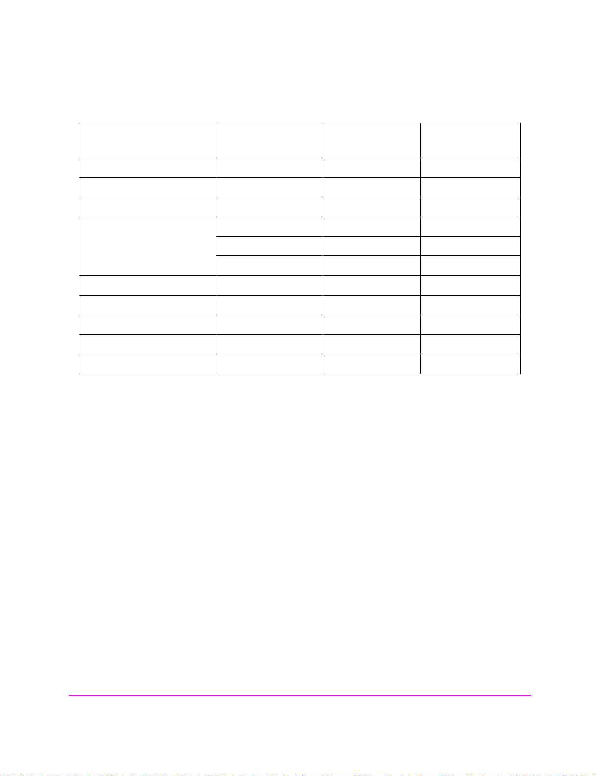
Table 2 Functions with HP-IB and Attribute Units That Can Be Change d
Function
Available
HP-IB Units
Applies to UNITs
Command
TX Power measurement W or DBM x x
Average Power measurement W or DBM x x
Channel Power measurement W or DBM x x
Adjacent Channel Power:
Lower Ratio, Upper Ratio
Lower Level, Upper Level
DB or PCT x x
W or DBM x x
xx
SINAD measurement DB or PCT x x
Distortion measurement DB or PCT x x
SNR measurement DB or PCT x x
RF Generator A mplitude W or DBM x
Frequency Error Hz x x
Applies to AUNits
Command
57
S:\HP8924C\USRGUIDE\BOOK\chapters\opoverv.fb
Page 58

Chapter 3, Operating Overview
To Enter and Change Values
To Enter and Change Values
To Enter Decimal Values
Values can be entered and changed using various methods, depending on your
testing needs. The unit-of-measure for some of these fields can also be changed
see "To Specify Units-of-Measure for HP-IB Data Transfer" on page 56).
(
1. Position the cursor in front of the numeric entry field to be changed.
2. Either:
• Enter the number and unit-of-measure directly using the keypad, or
• Press the CURSOR CONTROL knob or the ENTER key to highlight the field, and
use the knob, or
• Use the down-arrow and up-arrow keys to increment or decrement the present val-
ue.
Front-Panel Example
The following front panel operation changes Sector A Power to -73 dBm/BW.
1. Move the cursor in front of the Sector A Power field.
Enter −73 dBm using the DATA keys.
2.
HP-IB Example
The following HP-IB command also changes Sector A Power to
−73 dBm/BW.
“DISP CCNT;CDMA:CELL:ASEC -73 DBM;ASEC:STAT ON”
58
S:\HP8924C\USRGUIDE\BOOK\chapters\opoverv.fb
Page 59

To Enter and Change Values
To Enter Hexadecimal Values
Hexadecimal (Hex) values are used for entering some signaling parameters, such
as MIN (Mobile Identification Number). No unit-of-measure is associated with
these values.
Hexadecimal values are either entered from the keypad (using the A-F shifted
functions), or by using the
Front-Panel Example
The following front-panel operation enters the Hexadecimal number
#H0D2565F15 into the MIN field.
1. Move the cursor to the field below MS ID.
2. If the field currently says Phone Num press the ENTER key, use the CURSOR CON-
TROL knob to select MIN, and press the ENTER key again. (If MIN is already selected,
proceed to step 3.)
3. Use the CURSOR CON TROL knob to select the numeric entry field below MIN.
4. Enter 0, then press and release the SHIFT key, then the 3 key (to select D), enter 2565,
press and release the SHIFT key, then the 5 key (to select F), enter 15, and then press
the ENTER key. This is the hexadecimal code derived from the phone number
321-456-7890.
Chapter 3, Operating Overview
Choices menu.
HP-IB Example
The following HP-IB command also enters the Hexadecimal number 0D2565F15
into the MIN field.
“DISP CCNT;CDMA:MOB:MIN ‘0D2565F15’”
59
S:\HP8924C\USRGUIDE\BOOK\chapters\opoverv.fb
Page 60

Chapter 3, Operating Overview
To Enter and Change Values
To Enter Values With Exponents
Front-Panel Example
The following front-panel operation changes Confidence (limit) to 95.
1. Press the CALL CTRL key.
2. Move the cursor in front of the Confidence field.
3. Enter 9 EEX 1.
The EEX key can be used to enter values in exponential notation. Exponential
notation is only allowed on floating-point entry fields.
To Increment/Decrement Values
Incrementing and decr ement in g values on the Test Set c an b e pe rf ormed from the
front panel with the CURSOR CONTROL knob or the up/down arrow keys., or
the INCR
÷10 and INCR ×10 keys.
The INCR
÷10, INCR ×10, and INCR SET keys are used to assign a specific
increment value. To change an increment/decrement setting:
1. Move the cursor to the numeric entry field to be changed.
2. To change the current increment/decrement setting by a factor of 10, use the INCR ÷10
or INCR ×10 keys.
3. To set a specific increment/decrement value, press INCR SET, and enter the desired
value.
Front-Panel Example
The following front panel operation sets the increment value on the Sector A
Power
1. Press the CDMA SCRNS, CALL CTRL key.
2. Move the cursor in front of the Sector A Power field.
3. Press INCR SET, 3, ENTER.
4. Turn the knob or press the up/down arrow keys.
HP-IB Example
field to 3 dB.
The following HP-IB command also sets the increment value on the Sector A
Power
“DISP CCNT;CDMA:CELL:ASEC:INCR 3;INCR UP”
field to 3 dBm/BW, and increments the present value up by 3 dBm/BW.
60
S:\HP8924C\USRGUIDE\BOOK\chapters\opoverv.fb
Page 61

Saving and Recalling Instrument Setups
Saving and Recalling Instrument Setups
The save and recall functions allow you to store different instrument setups and
retrieve them later, eliminating the task of re-configuring the Test Set.
The number of available sa ve regi ster s depends on how many cha nges were made
to the BASE instrument setup for each save. (See
page 64
registers that can be used (typically over 200).
SAVE/RECALL register settings can be saved to several types of mass storage.
This allows you to “back up” the settings in case you need to clear them from
memory (see
when a firmware upgrade is performed.
To Save an Instrument Setup
1. Press and release the SHIFT key, then the PREV key to access the I/O CONFIGURE
2. Make any changes to the instrument that you want to save in a register.
3. Press and release the SHIFT key, then the RECALL key to select the SAVE function.
4. Use the DATA keys or the Save: menu at the bo ttom right of the screen to enter the
.) The smaller the number of changes, the greater the number of SAVE
"Memory Considerations" on page 64 ) for running large programs, or
screen. Select the storage media using the Save/Recall field. (The default storage
media is internal memory.)
save register name.
Chapter 3, Operating Overview
"Specifying BASE Settings" on
Front-Panel Example
This example saves the current instrument settings.
1. Press and release the SHIFT key, then the RECALL key to select the SAVE function.
A prompt appears at the top of the screen asking you to enter a name.
2. Using the DATA keys, enter 123, then press the ENTER key to assign a name.
HP-IB Example
The following HP-IB command also SAVES the current instrument settings.
“REG:SAVE 123”
61
S:\HP8924C\USRGUIDE\BOOK\chapters\opoverv.fb
Page 62

Chapter 3, Operating Overview
Saving and Recalling Instrument Setups
To Recall an Instrument Setup
1. Press and release the SHIFT key, then the PREV key to access the I/O CONFIGURE
screen and select the media to recall settings from using the Save/Recall field. (The
default is internal memory.)
2. Press the RECALL key.
3. Use the knob to select the desired setup to be recalled from the Recall menu at the
bottom right of the screen.
Front-Panel Example
This example recalls t he current instrument settings.
Press RECALL, 1, 2, 3, ENTER. The saved instrument settings are recalled.
HP-IB Example
The following HP-IB command also recalls register 123.
“REG:REC 123”
To Clear All SAVE Registers
1. Press the RECALL key.
2. Use the knob to position the cursor in front of the entry in the Recall menu at the
bottom right of the screen.
3. Press the knob or the ENTER key. A prompt appears at the top of the screen to verify
that you want to clear all registers.
4. Press the ON/OFF key to select YES.
HP-IB Example
The following HP-IB command clears all registers
“REG:CLE:ALL”
62
S:\HP8924C\USRGUIDE\BOOK\chapters\opoverv.fb
Page 63

Saving and Recalling Instrument Setups
To Remove (Clear) an Individual SAVE Register
1. Specify where the register is stored using the Save/Recall field on the I/O CON-
FIGURE screen.
2. Press the RECALL key.
3. Use the knob to position the cursor in front of the register to be removed from the Re-
call menu at the bottom right of the screen. The register name and percentage of
SAVE memory occupied by that register are indicated at the very top of the screen.
4. Press the ON/OFF key. A prompt appears, asking if you want to delete the save register.
5. Press the ON/OFF key to select YES. (Press the RATIO W key to select NO.)
HP-IB Example
The following HP-IB command clears a register
“REG:CLE ‘<quoted string>’”
Choosing Register Names
You can use any number, letter, or combination of numbers and letters as a name
for storing instrument settings. For instance; if you want to save a setup for testing
a “Vulcan7” radio, you can save the setting as “VULCAN7”.
Chapter 3, Operating Overview
Two register names are reserved for special purposes: POWERON and BASE.
Specifying POWERON Settings
You can specify the instrument setting at power-on by following the procedure
described in
name POWERON. If a SAVE Register named P OWERON is detected b y the Test
Set during its power-on r outine, the Test Set wil l confi gure itse lf usi ng the s ettings
stored in the POWERON register.
NOTE: If the Test Set does not successfully complete its power-on routine because of the POWERON
settings (e.g., the Test Set displays a message that requires you to cycle power to recover) you
must:
1. Turn off the Test Set.
2. Hold down the PRESET and the Hz/uV keys simultaneously.
3. Turn on power while holding the PRESET and the Hz/uV keys down until the CALL
CONTROL screen appears.
This procedure will clear all SAVE registers, including POWERON.
"To Save an Instrument Setup" on page 61, and choosi ng the regi st er
63
S:\HP8924C\USRGUIDE\BOOK\chapters\opoverv.fb
Page 64

Chapter 3, Operating Overview
Saving and Recalling Instrument Setups
Specifying BASE Settings
The BASE register contains any f i eld settings the user has SAVEd that are
different from th e instrumen t PRESET state. I t establ ishes a re feren ce point for all
future SAVEs. (The PRESET state is st ored i n the BASE regi ster unt il yo u SAVE
another instrument setup.)
When you SAVE an instrument setup, the new setup is compared to the BASE
settings, and any differences are stored under the register name you supply.
Because only differences are stored, a much larger number of instrument setups
can be saved than if the contents of every field was saved.
When you RECALL an instrument setting, every field is reset to the BASE
settings. T he SAVED set tings are then used to re-establish the desired instrument
setup.
You can define your own BASE setting . If your desire d setti ngs are very dif ferent
from the PRESET values, you may want to change the BASE register. This will
decrease the amount of memory used to SAVE each setup, and allow you to
SAVE many more setups.
CAUTION: Since each SAVE/RECALL register only contains the differences between the setup being
saved and the present BASE register settings, changing the BASE results in all other saved
setups being ERASED from memory (including the POWERON setting if one has been
saved).
Unless you consistently change the same fields to the same value each time you
use the instrument, you should probably not create your own BASE settings .
Memory Considerations
When the Save/Recall field of the I/O CONFIGURE screen is set to
Internal, instrument setups are saved to the same non-volatile RAM used to
create RAM Disk(s) and run IBASIC programs. By saving a large number of
instrument setups, you reduce the amount of RAM available to run programs. If
you get a “memory overflow” message while trying to load a program, you must
clear one or more SAVE/RECALL registers to free RAM space).
64
S:\HP8924C\USRGUIDE\BOOK\chapters\opoverv.fb
Page 65

Using USER Keys
Using USER Keys
Chapter 3, Operating Overview
User keys instantly access instrument settings without using the knob. You can
use USER keys to move quickly betwee n fields on the same screen, an d to a cce ss
field settings that are not normally available on the screen you are using.
Local USER keys are used to move between settings on the screen that is
displayed. When the USER key is pressed, the cursor instantly moves to, and
selects, the assigned field; eliminating the need to turn and push the knob. Five
local USER keys are available for each screen: K1, K2, K3, K4, and K5.
Global USER keys are used to acce ss sett in gs that are not ava ilabl e on the cur ren t
screen. Three global USER keys are available: K1’, K2’, and K3’. (These are
shifted functions of the local USER keys.)
When defining USER keys, the ASSIGN f unctio n is used to c reate key definiti ons;
the RELEASE function removes the definitions. Re-assigning a USER key to a
different fi eld setting au tomatically Releases it fro m the setting it was previously
associated with.
To Assign Local USER Keys
1. Move the cursor to the field you want to assign a local USER key to.
2. Press and release the SHIFT key, then the K4 key to select the ASSIGN function. Press
a local USER key (K1-K5). The USER key number appears in front of the field you
assigned it to.
Example of Assigning a Local USER Key
Use this example to assign local USER key K1 to the Filter 1 field in the RX
TEST screen.
1. Access the RX TEST screen and position the cursor in front of the Filter 1 field.
2. Press and release the SHIFT key, then the K4 key to select the ASSIGN function.
3. Press K1. A small 1 appears next to the field indicating that USER key K1 has been
assigned to it.
4. Move the cursor to any other field on the screen and press K1. The cursor immediately
returns to the Filter 1 field. The field is also highlighted to change the entry using
the CURSOR CONTROL knob or arrow keys.
65
S:\HP8924C\USRGUIDE\BOOK\chapters\opoverv.fb
Page 66

Chapter 3, Operating Overview
Using USER Keys
To Release Local USER Keys
1. Display the screen containing the USER key assignment to be removed.
2. Press and release the SHIFT key, then the K5 key to select the RELEASE function.
3. Press the USER key (K1-K5) that you want to release.
To Assign Global USER Keys
1. Move the cursor to the field you want to assign a global USER key to.
2. Press and release the SHIFT key, then the k4 key to select the ASSIGN function.
3. Press a global USER key (K1’ -K3’). Unlike a local USER key, the USER key number
does not appear in front of the field you assigned a global USER key to. A prompt appears at the top of the screen confirming the key assignment.
Example of Assigning a Globa l USE R Key
Use this example to assign global USER key K1’ to the AF Anl In field, and
then access this field in the OSCILLOSCOPE screen.
1. Access the AF ANALYZER screen and position the cursor in front of the AF Anl In
field.
2. Press and release the SHIFT key, then the K4 key to select the ASSIGN function.
3. Press and release the SHIFT key, then the K1’ key. Notice the prompt Global User
key 1 assigned. at the top of the screen.
4. Access the OSCILLOSCOPE screen.
5. Press SHIFT, K1’.
AF Anl Input
present input is set to FM Demod). To change the input, use the arrow keys, or
press the ENTER key to access the
A field that is ac cessed us ing a glob al USER key i s only dis played at the top of the
screen while it is being accessed. Moving the cursor to any other field in the
screen causes the USER key field to disappear until it is accessed again.
To Release Global USER Keys
1. Move the cursor to the field with the global USER key assigned to it.
2. Press SHIFT, K5, SHIFT, and the USER key to be released (K1’-K3’).
, FM Demod is displayed at the top of the screen (assuming the
Choices menu.
66
S:\HP8924C\USRGUIDE\BOOK\chapters\opoverv.fb
Page 67

Chapter 3, Operating Overview
Setting an RF Generator/Analyzer Frequency Offset
Setting an RF Generator/Analyzer Frequency Offset
You can set a fixed frequency offset between the RF Generator and the RF
Analyzer. At power-up and instrument preset this feature is ON with a
transmit/receive frequency offset of 45 MHz.
NOTE: A 45 MHz offset is required for making a call or making measurements in CDMA mode.
To Turn Off RF Frequency Offset
1. Access the CONFIGURE screen.
2. Position the cursor below the RF Display field and select Freq.
3. Set the RF Offset to Off
HP-IB Example
“CONF:OMOD ‘OFF’”
turns the RF frequency offset off
To Change the RF Frequency Offset
1. Access the CONFIGURE screen.
2. Position the cursor below the RF Display field and select Freq.
3. Set the RF Offset to On
4. Enter an offset frequency ((Gen)-(Anl)).
.
.
67
S:\HP8924C\USRGUIDE\BOOK\chapters\opoverv.fb
Page 68

Chapter 3, Operating Overview
Setting an RF Generator/Analyzer Level Offset
Setting an RF Generator/Analyzer Level Offset
You can correct for path loss by setting up an RF Level Offset on the front-panel
RF connector(s) used in your application. At power-up and instrument preset this
feature is OFF with 0.0 dB loss in all connector fields.
An RF Level Offset is required t o ensure proper powe r levels to the anal yzer when
testing CDMA mobile stations.
Refer to “Determining and Correcting for RF Path Loss” in Calibrating the Test
Set chapter of the HP 8924C Application Guide.
68
S:\HP8924C\USRGUIDE\BOOK\chapters\opoverv.fb
Page 69
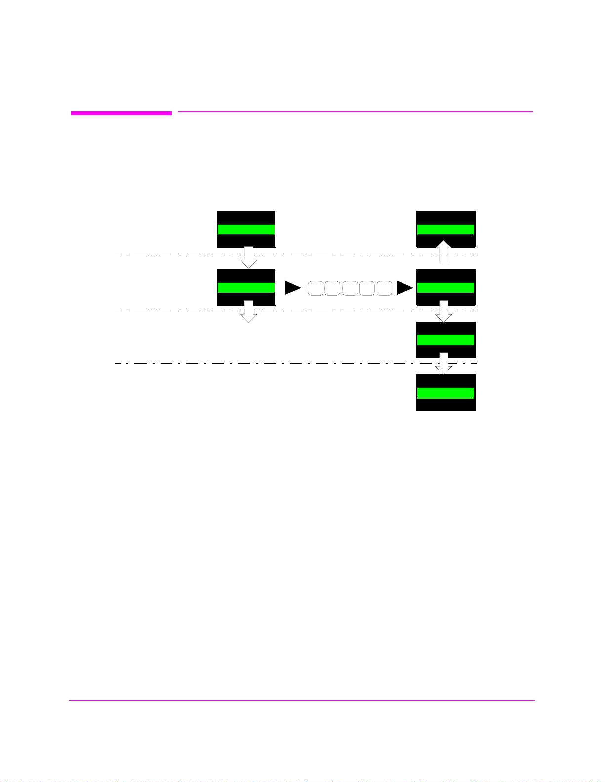
Interaction Between Screens
Interaction Between Screens
Most fields operate globally; changing the setting in any screen automatically
changes th at setting in all screens where it is available.
example of this field type.
Chapter 3, Operating Overview
AFGen1 Freq is an
AFGen1 Freq
1.000
RX TEST
AFGen1 Freq
RF GENERATOR
kHz
1.000
kHz
TX TEST
DUPLEX
Figure 6 Example of How Global Fields Work
Priority fields give the RX TEST and TX TEST screens priority control of their
settings. No matter what these fields were set to in other screens, if the RX TEST
or TX TEST screen is accessed, the field changes to whatever it was last set to in
these screens. The RF Generator
These fields and their preset values are listed in
AFGen1 Freq
1.250
kHz
DATA Keys
AFGen1 Freq
.
21 5 0
1.250
kHz
AFGen1 Freq
1.250
kHz
AFGen1 Freq
1.250
kHz
Amplitude is an example of this field type.
table 3 on page 70.
69
S:\HP8924C\USRGUIDE\BOOK\chapters\opoverv.fb
Page 70
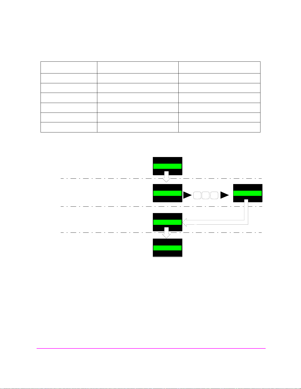
Chapter 3, Operating Overview
Interaction Between Screens
Table 3 Priority RX TEST and TX TEST Fields
Priority Field RX TEST TX TEST
RF Gen Amplitude Presets to −80 dBm (changeable) Always Off
AFGen1 To Presets to FM (changeable) Always Audio Out
AF Anl In Always Audio In Presets to FM Demod (changeable)
Detector Always RMS Presets to Pk +− Max(changeable)
De-emphasis Always Off Presets to 750µs (changeable)
AF Anl Measurement Presets to SINAD (changeable) Presets to Audio Freq (changeable)
Using your Test Set, duplicate the steps in figure 7 to demonstrate how the
priority fields operate.
1. Access the RX TEST screen and set the
Amplitude
Amplitude to -50 dBm.
2. Access the RF GENERATOR screen and
Amplitude
set the Amplitude to -75 dBm.
3. Access the RX TEST screen. Notice that
Amplitude
the Amplitude changes back to -50 dBm.
2. Return to the RF GENERATOR screen.
Amplitude
The Amplitude is no longer where you set it
in step 2 (-75 dBm).
Since the RX TEST screen has priority control over this field, the RF GENERATOR screen’s
Amplitude setting changed when RX TEST was accessed.
Figure 7 Example of How Priority Fields Work
-50
-50
-50
-50
dBm
dBm
dBm
dBm
- 7 5
Amplitude
-75
dBm
70
S:\HP8924C\USRGUIDE\BOOK\chapters\opoverv.fb
Page 71

Printing A Screen
Printing A Screen
To Print A Screen’s Contents
1. Connect a printer to the appropriate rear-panel connector.
2. Press and release the SHIFT key, then the PRINT key to access the PRINT CONFIG-
URE screen and set the Printer Port field to the appropriate type of printer con-
nection.
• If HP-IB is selected, enter the HP-IB Printer Address of the printer.
3. Select the type of printer you are using in the Model field. If your printer is not lis ted,
configure your printer to emulate one that is listed.
4. Enter a Print Title using the knob (optional). The title will appear at the top of
your printout.
5. Display the screen you want to print and press the PRINT key.
Chapter 3, Operating Overview
To interrupt prin ti ng, select the Abort Print fiel d on the PRINT CONFIGURE
screen.
71
S:\HP8924C\USRGUIDE\BOOK\chapters\opoverv.fb
Page 72

Chapter 3, Operating Overview
Measurement Triggering Process
Measurement Triggering Process
Active Measurements
Only active measurements can be triggered and then queried for a measurement
result. Within the Test Set, measurements are differentiated between those that are
"active" and those that ar e "not active". The definition of an ac tive measurement is
different for analog measurements than for CDMA measurements.
Definition of Active CDMA Measurement
All CDMA measurements are "active" if:
• either of the following screens is displayed on the CRT of the Test Set
CDMA CELLULAR MOBILE RECEIVER TEST
CDMA CELLULAR MOBILE TRANSMITTER TEST
AND
• the measurement is in the ON state
NOTE: Only the Avg/Chan Power measurement is active on the CDMA CALL CONTROL screen.
Definition of Active Analog Measurement
An analog measurement is "active" if:
• the field used to display the measurement result is located on the screen which is
currently displayed on the CRT of the Test Set
AND
• the measurement is in the ON state
72
S:\HP8924C\USRGUIDE\BOOK\chapters\opoverv.fb
Page 73

Measurement Triggering Process
Triggering A Measurement Cycle
The Test Set starts a measurement cycle when a valid trigger is received. The
measurement cycle is the process used by the Test Set to obtain measurement
results.
The measurement cycle is a fi rmware pr ocess which, for all ac tive mea surement s,
obtains raw data from the hardware and then processes/formats the raw data into a
measurement result. The result is then displayed on the screen, and - if operating
in remote mode - sent to the HP-IB bus.
The measurement cycle completes when a valid measurement result is obtained
for all active measurements.
Trigger Modes
The trigger mode used to sta rt the measur emen t cy cle can be selected by the use r.
The trigger mo de is defined by two parameters: retrigger ing and settling.
Chapter 3, Operating Overview
Retriggering
Retriggering refers to what the measurement cycle does once it has completed
(obtained a valid measurement result for all active measurements). There are two
options:
1. Single retriggering causes the measurement cycle to sto p once a valid m easurement re-
sult has been obtained for all active measurements. A valid trigger must be received to
start the measurement cycle again. When a measurement cycle is completed, the values
for all active measurements are held until another trigger is received.
2. Repetitive retriggering causes the measurement cycle to automatically start over once
a valid measurement result has been obtained for all active measurements. No trigger
must be received to start the measurement cycle again. Repetitive retriggering will
cause measurements that rely on external signals or hardware generated events (such as
Traffic Rho) to be automatically re-armed upon completion of a measurement cycle.
NOTE: The Cont selection in the Meas Cntl field is equal to repetitive retriggering.
73
S:\HP8924C\USRGUIDE\BOOK\chapters\opoverv.fb
Page 74

Chapter 3, Operating Overview
Measurement Triggering Process
Settling
Settling refers to the amount of ti me de lay introduced int o t he mea surement cycle
to allow signal transients to propagate through the analysis chain and settle out.
There are two options:
1. Full settling introduces the appropriate delay for all signal transients which might have
occurred at the front panel coincident with the trigger command, to pass through the
analysis chain and settle out. Delays are also inserted to allow for internal hardware
transients to settle.
2. Fast settling introduces no delay for internal or external signal transients to settle.
There will still be delays introduced by the couplings between autotuning and autoranging. If the operator wishes to remove these delays as well, all autoranging and
autotuning functions must be turned OFF and the operator must explicitly set the ranging amplifiers and the frequency tuning. Delays introduced by the measurement processes themselves cannot be eliminated.
NOTE: CDMA measurements are not affected by the trigger mode settling parameter. CDMA
measurements are made with a digital signal processor (DSP) which does not require the
settling times associated with analog hardware circuitry.
Rho Suite of Measurements
The following group of CDMA measurements is referred to as the "Rho Suite of
Measurements" because a result for each of the following measurements is
available each time the Rho Suite of measurements is triggered:
Traffic Rho or TM Rho (only one can be selected)
Frequency Error
Amplitude Err or
Time Offset
Phase Error
Carrier Feedthrough
74
S:\HP8924C\USRGUIDE\BOOK\chapters\opoverv.fb
Page 75

Measurement Triggering Process
Default Trigger Modes
Default Trigger Mode for Remote Operation: CDMA and Analog Measurements
Upon powerup, or upon receiving a *RST command, or upon pressing the front
panel PRESET key, the Test Set’s default trigger mode for remote operation of
both CDMA and analog measurements is Repetitive
settling.
If a local-to-remote transition occurs, the trigger mode will be set to the last
trigger mode command received while in remote mode. If no trigger mode
command has been received since powerup, the default state is set.
Default Trigger Mode for Local Operation: CDMA Measurements
Upon powerup, or upon receiving a *RST command, or upon pressing the front
panel PRESET key, the Test Set’s default trigger mode for front panel operation
of the FER and Rho Suite of Measurements is Single retriggering.
If a remote-to-local transition occurs, the trigger mode will be determined by:
Chapter 3, Operating Overview
retriggering with Full
• FER - the state of the Meas Cntl field on the CDM A CELLULAR MOBILE
RECEIVER TEST screen
Rho Suite of Measurements - the state of th e Meas Cntl field on the CDMA
•
CELLULAR MOBILE TRANSMITTER TEST screen
NOTE: Setting the Meas Cntl field to Cont (Continuous) sets the trigger mode to repetitive
retriggering.
Upon powerup, or upon receiving a *RST command, or upon pressing the front
panel PRESET key, or upon a remote-to-local transition the Test Set’s default
trigger mode for front panel operation of the Avg/Chan Power measurement is
Repetitive retriggering.
Default Trigger Mode for Local Operation: Analog Measurements
Upon powerup, or upon receiving a *RST command, or upon pressing the front
panel PRESET key, the Test Set’s default trigger mode for front panel operation
of analog measurements is Repetitive
retriggering with Full settling.
75
S:\HP8924C\USRGUIDE\BOOK\chapters\opoverv.fb
Page 76
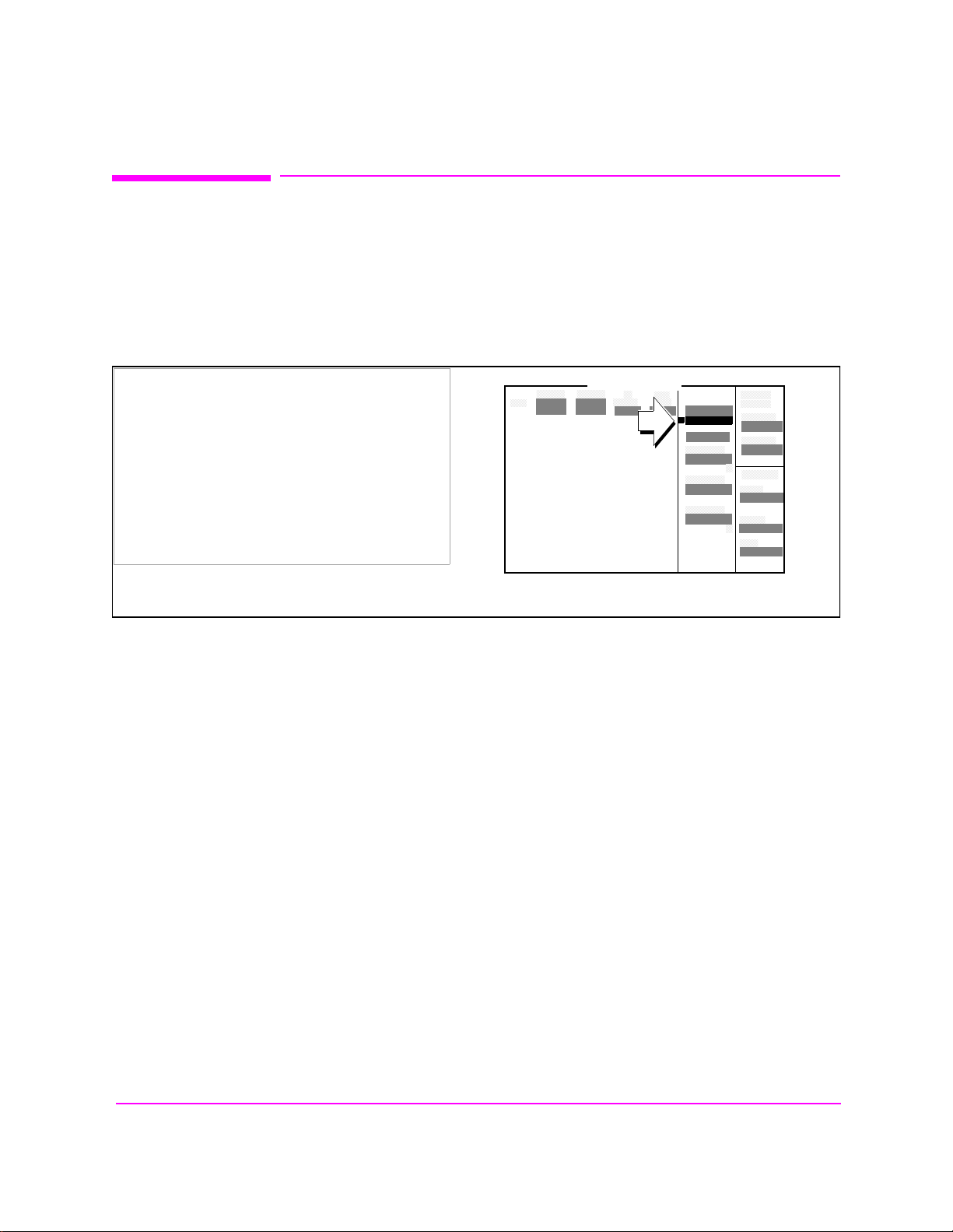
Chapter 3, Operating Overview
Triggering Analog Measurements In Local Mode (Front Panel Operation)
Triggering Analog Measurements In Local Mode (Front Panel Operation)
1. Select the desired trigger mode.
For Signaling
Decoder
• Continuous - Once a measurement has completed, the Test Set is internally re-
triggered and another measurement cycle begins.
• Single - Requires selection of the Arm Meas field to be begin a measurement cycle.
Manual Operation:
1. Position the cursor at the Single/Cont field.
2. Press the knob to underline the desired mode.
SIGNALING DECODER
Arm
Single/Cont
76
S:\HP8924C\USRGUIDE\BOOK\chapters\opoverv.fb
Page 77
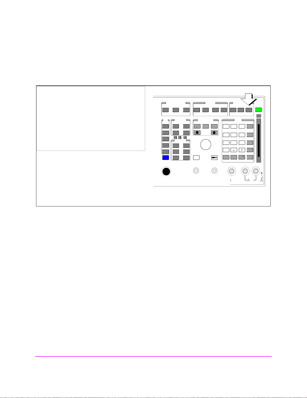
Triggering Analog Measurements In Local Mode (Front Panel Operation)
Chapter 3, Operating Overview
For Analog
Measurements (other
than Signaling
Decoder)
• Repetitive retriggering is the only trigger mode available from the front panel for
analog measurements (other than the Signaling Decoder). Single trigger mode can be
simulated using the Test Set’s measurement hold feature. Selecting the HOLD key
causes all currently displayed measurement results to be held on the screen and stops
the measurement cycle. To resume making measurements press the HOLD key again.
Manual Operation:
1. Press then release the SHIFT key, then press the
MEAS RESET key to HOLD measurement results.
2. Select HOLD again to return to Repetitive mode.
CDMA CALL CONTROL
CDMA SCRNS
CELL
CALL
CTRL
SPECTRUM
GEN
CTRL
ANALOG SCRNS
ENCODER
RF
ANL
AF
ANL
SPEC ANL
RF
GEN
END
CALL
RANGE
RX
TEST
MSRPT
TEST
DECODER
RX
TEST
ACP
TEST
SCOPE
DUPLEX
TX
TX
CALL ANS
USER DATA
k1’
k1
k2’
k2
k3’
k3
ASSIGN
k4
RELEASE
k5
FUNCTIONS
MSG
PRINTER
HELP
PRINT
DATA FUNCTIONS
REF SET
METER
INCR
INCR
: 10
SET
LO LIMIT HI LIMIT
CURSOR
CONTROL
CANCELSHIFT
I/O CONFIG CONFIG
INCR X10
PUSH TO
SELECT
Meas Reset begins a measurement cycle, interrupting any measurement in progress.
PREV TESTS
AVG
INSTRUMENT STATE
ADRS
SAVE
LOCAL
RECALL
789
456
123
+
0
ON/OFF
YES
Ω
NO
%
ppm
dBµV
W
AUDIO OUTSQUELCHVOLUMEMIC/ACC
MAX
!
12 v Pk
HOLD
MEAS
PRESET
RESET
MEMOR
Y CARD
ENTER
dB
GHz
dBm
%
MHz
V
s
kHz
_
mV
ms
Hz
µV
AUDIO IN
LOHI
MAX
!
42 v Pk
77
S:\HP8924C\USRGUIDE\BOOK\chapters\opoverv.fb
Page 78
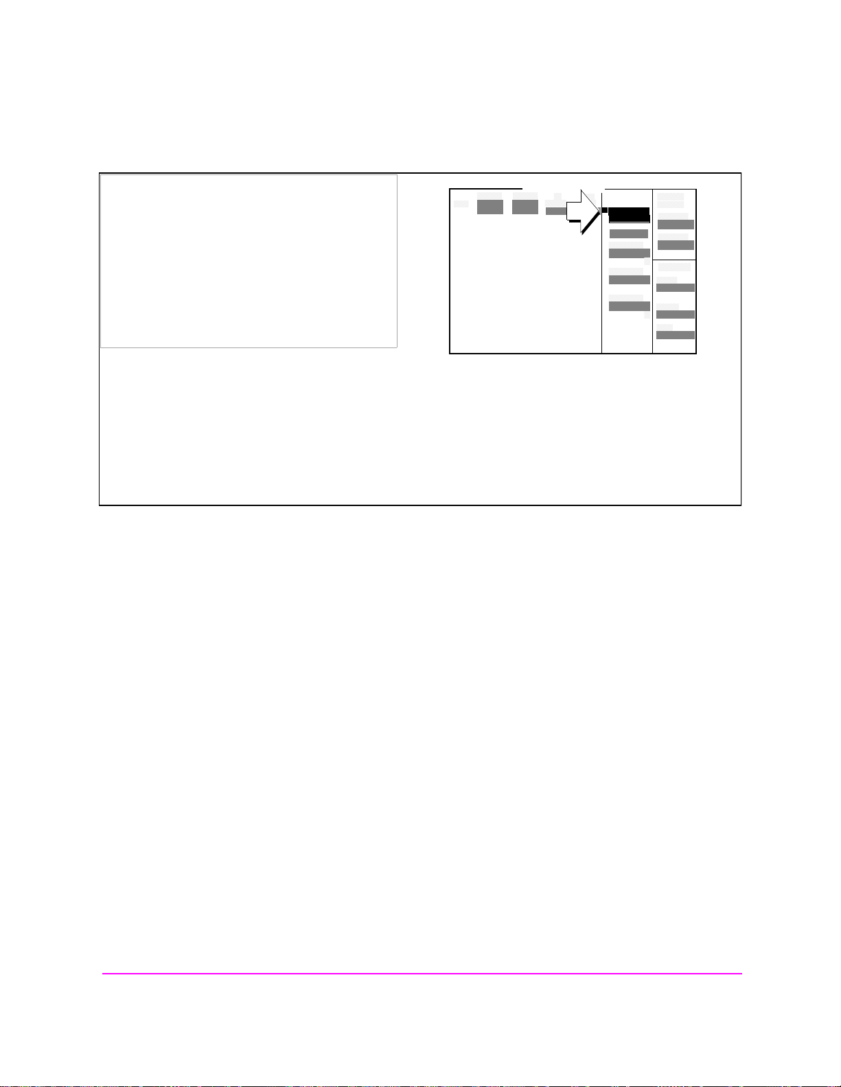
Chapter 3, Operating Overview
Triggering Analog Measurements In Local Mode (Front Panel Operation)
2. Trigger the Signaling Decoder (applies if trigger mode is "Single")
Manual Operation:
1. Position the cursor at the Arm Meas field.
SIGNALING DECODER
Arm Meas
Single/Cont
2. Press the knob.
Arming the Signaling Decoder as shown in this example will cause the measurement to be automatically triggered by an internal trigger command.
Selecting the Stop Meas field will stop the currently executing measurement cycle for the Signaling
Decoder.
78
S:\HP8924C\USRGUIDE\BOOK\chapters\opoverv.fb
Page 79
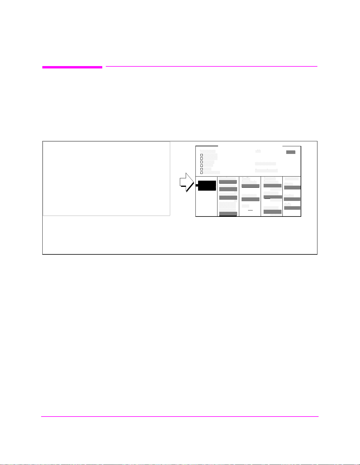
Chapter 3, Operating Overview
Triggering CDMA Measurements In Local Mode (Front Panel Operation)
Triggering CDMA Measurements In Local Mode (Front Panel Operation)
1. Select the desired trigger mode.
For FER and Rho
Suite of
Measurements
Manual Operation:
1. Position the cursor at the Single/Cont field.
2. Press the knob to underline the desired mode.
• Continuous - Once a measurement has completed, the Test Set is internally re-
triggered and another measurement cycle begins.
• Single - Requires selection of the Arm field to be begin a measurement cycle.
CDMA CELLULAR MOBILE RECEIVER TEST
Test Status
Connected
Svc Opt 2
Testing
Passed
Failed
Max Frames
Meas Cntl
Single/Cont
Arm
Disarm
Max Frames
On/Off
Confidence
95.00
FER Specs
3.00
Display
Interim
Results
Yes/No
%
%
Traffic
Data Mode
Svc Opt 1
Data Rate
Full
Eb/Nt
----
FER
Errors Counted
Frames Counted
Sector A
Power
-75.0
dBm/BW
Traffic
15.6
AWGN
-75.0
dbm/BW
dB
To Screen
CDMA
CALL CNTL
Analog
RX TEST
Cnfig
PRNT CNFG
When Single is selected, the Arm and Disarm fields are displayed. When Continuous is selected the
Arm and Disarm fields will not appear.
%
79
S:\HP8924C\USRGUIDE\BOOK\chapters\opoverv.fb
Page 80
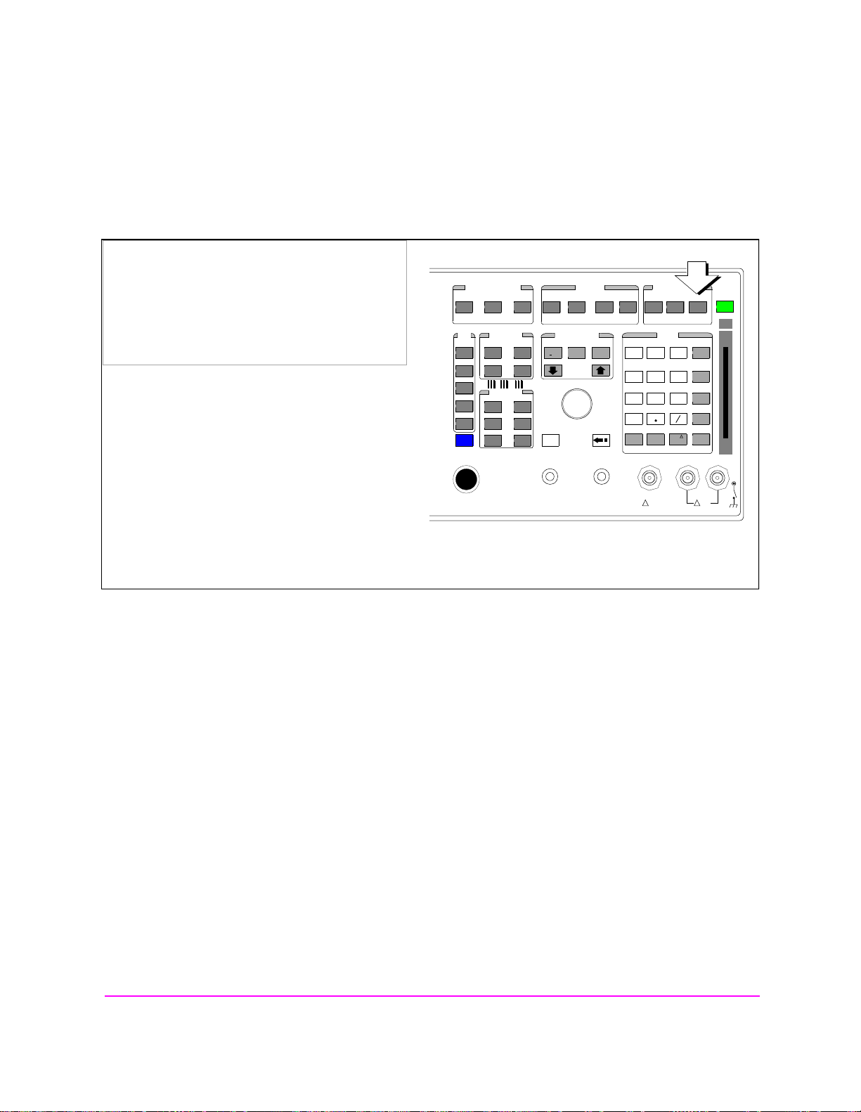
Chapter 3, Operating Overview
Triggering CDMA Measurements In Local Mode (Front Panel Operation)
For Avg Power and
Chan Power
measurements
• Repetitive retriggering is the only trigger mode available from the front panel for
the Avg Power and Chan Power measurements. Single trigger mode can be simulated
using the Test Set’s measurement hold feature. Selecting the HOLD key causes all
currently displayed measurement results to be held on the screen and stops the
measurement cycle. To resume making measurements press the HOLD key again.
Manual Operation:
1. Press then release the SHIFT key, then press the
MEAS RESET key to HOLD measurement results.
2. Select HOLD again to return to Repetitive mode.
CDMA CALL CONTROL
CDMA SCRNS
CELL
CALL
CTRL
SPECTRUM
GEN
CTRL
ANALOG SCRNS
ENCODER
RF
ANL
AF
ANL
SPEC ANL
RF
GEN
END
CALL
RANGE
RX
TEST
MSRPT
TEST
DECODER
RX
TEST
ACP
TEST
SCOPE
DUPLEX
TX
TX
CALL ANS
USER DATA
k1’
k1
k2’
k2
k3’
k3
ASSIGN
k4
RELEASE
k5
FUNCTIONS
MSG
PRINTER
HELP
PRINT
DATA FUNCTIONS
REF SET
METER
INCR
INCR
: 10
SET
LO LIMIT HI LIMIT
CURSOR
CONTROL
CANCELSHIFT
I/O CONFIG CONFIG
AVG
INCR X10
PUSH TO
SELECT
Meas Reset begins a measurement cycle, interrupting any measurement in progress.
PREV TESTS
INSTRUMENT STATE
ADRS
SAVE
LOCAL
RECALL
789
456
123
+
0
ON/OFF
YES
Ω
NO
%
ppm
dBµV
W
AUDIO OUTSQUELCHVOLUMEMIC/ACC
MAX
!
12 v Pk
HOLD
MEAS
PRESET
RESET
MEMOR
Y CARD
ENTER
dB
GHz
dBm
%
MHz
V
s
kHz
_
mV
ms
Hz
µV
AUDIO IN
LOHI
MAX
!
42 v Pk
80
S:\HP8924C\USRGUIDE\BOOK\chapters\opoverv.fb
Page 81
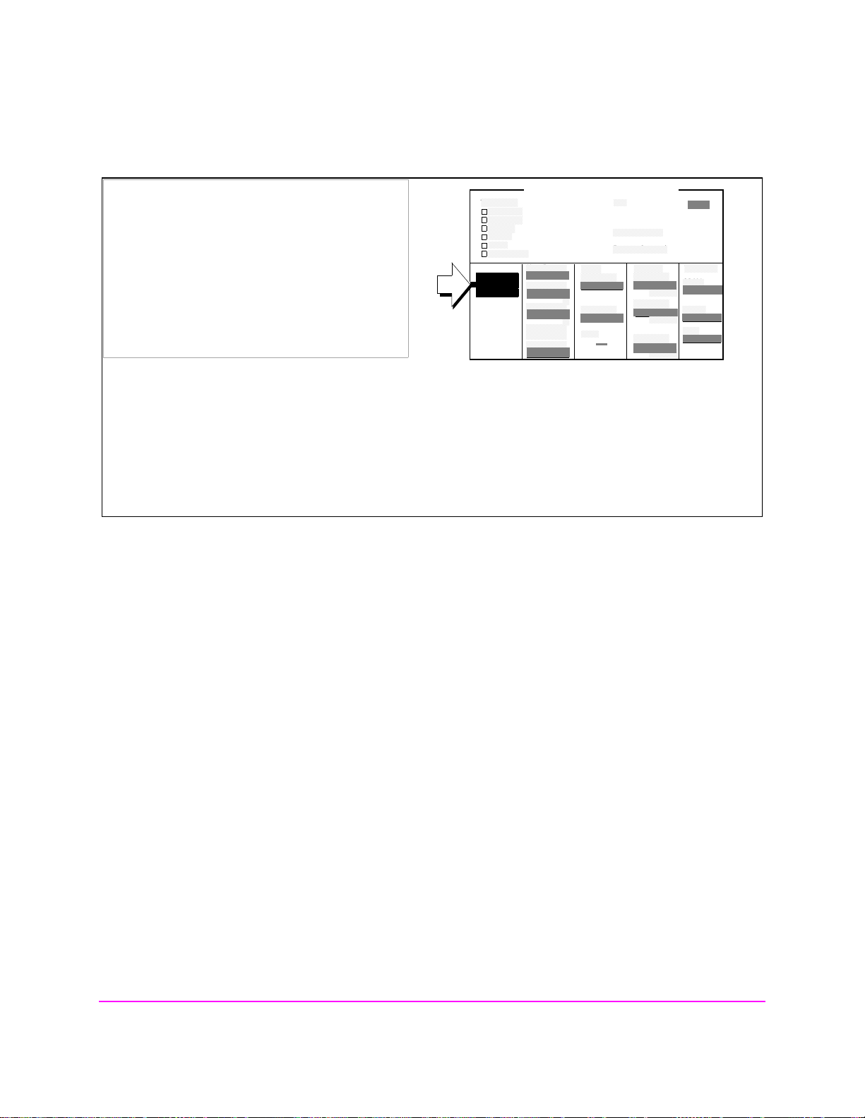
Chapter 3, Operating Overview
Triggering CDMA Measurements In Local Mode (Front Panel Operation)
2. Trigger the FER and Rho Suite Measurements (applies if trigger mode is "Single")
Manual Operation:
1. Position the cursor at the Arm field.
2. Press the knob.
Test Status
Meas Cntl
Single/Cont
Arm
Disarm
CDMA CELLULAR MOBILE RECEIVER TEST
Connected
Svc Opt 2
Testing
Passed
Failed
Max Frames
Max Frames
On/Off
Confidence
FER Specs
Display
Interim
Results
Yes/No
95.00
3.00
%
%
Traffic
Data Mode
Svc Opt 1
Data Rate
Full
Eb/Nt
FER
Errors Counted
Frames Counted
----
Sector A
Power
-75.0
dBm/BW
Traffic
15.6
AWGN
-75.0
dbm/BW
dB
%
To Screen
CDMA
CALL CNTL
Analog
RX TEST
Cnfig
PRNT CNFG
Arming the FER measurement as shown in this example will cause the measurement to be triggered
by an internal trigger event. The Rho suite of measurements operate similarly.
Selecting the Disarm field will stop the currently executing measurement cycle for the FER or Rho
Suite of Measurements.
81
S:\HP8924C\USRGUIDE\BOOK\chapters\opoverv.fb
Page 82

Chapter 3, Operating Overview
Triggering Analog Measurements In Remote Mode (HP-IB Operation)
Triggering Analog Measurements In Remote Mode (HP-IB Operation)
1. Select the desired trigger mode.
• Retriggering
• Repetitive - Once a measurement cycle has completed
ically re-triggered and another measurement cycle begins.
When the trigger mode is set to repetitive retriggering, consecutiv e que ri es of the
same measurement return new measured values.
• Single - Once a measurement cycle has completed the Test Set requires an
HP-IB trigger command be received to begin a new measurement cycle.
When the trigger mode is set to single retriggering, consecutive queries of the
same measurement (with no intervening trigger) will return the same value. Measurements that rely on external signals or hardware-generated events (such as Traffic Rho) must be re-armed with a new trigger before another measurement can be
made.
• Settling
• Full - Appropriate time delays introduced into measurement cycle to allow inter-
nal or external signal transients to settle.
• Fast - No time delay introduced into measurement cycle to allow internal or ex-
ternal signal transients to settle.
The programmer must account for transient settling before issuing a trigger command.
There will still be delays introduced by the couplings between autotuning and
autoranging. If the programmer wishes to remove these delays as well, all autoranging and autotuning functions must be t urned OFF and the prog ram must expli citly set the ranging amplifiers and the frequency tuning. Delays introduced by the
measurement processes themselves cannot be eliminated.
the Test Set is automat-
HP-IB Syntax|
"TRIG:MODE:RETR REP" !selects Repetitive retriggering mode.
"TRIG:MODE:RETR SING" !selects Single retriggering mode.
TRIG:MODE:SETT FULL" !selects Full settling mode.
"TRIG:MODE:SETT FAST" !selects Fast settling mode.
82
S:\HP8924C\USRGUIDE\BOOK\chapters\opoverv.fb
Page 83

Chapter 3, Operating Overview
Triggering Analog Measurements In Remote Mode (HP-IB Operation)
2. Trigger all active analog measurements (applies if trigger mode is "Single")
HP-IB Syntax
"TRIG" !triggers all active analog measurements.
HP-IB Example Program
10 OUTPUT 714;"DISP RFAN"
20 OUTPUT 714;"TRIG:MODE:RETR SING;SETT FULL"
30 OUTPUT 714;"TRIG"
40 END
HP-IB Example Program Comments By Line
10 !Selects RF Analyzer screen
20 !Sets the Test Set’s remote trigger mode to Single retriggering and Full settling
30 !Triggers all active analog measurements
Preventing HP-IB Bus Lockup
HP-IB bus lockup is a condition where the HP-IB bus and the Active Controller
handshake are in a temporary holdoff state while the Active Controller waits to read the
measurement result from the Test Set. If a measurement cycle do es not successfully obtain
a valid measurement result, it will continue to try until it does or until the measurement
trigger is aborted. This is true for both retriggering modes. This has the consequence of
putting the HP-IB in the lockup state.
The control program should include measurement time-out routines that CLEAR the bus
and ABORt the trigger if a measurement does not complete within a specified amount of
time. This provides a method of preventing the bus from remaining in the temporary
holdoff state indefinitely.
83
S:\HP8924C\USRGUIDE\BOOK\chapters\opoverv.fb
Page 84

Chapter 3, Operating Overview
Triggering CDMA Measurements In Remote Mode (HP-IB Operation)
Triggering CDMA Measurements In Remote Mode (HP-IB Operation)
1. Select the desired trigger mode.
• Retriggering
• Repetitive - Once a measurement cycle has completed
ically re-triggered and another measurement cycle begins.
When the trigger mode is set to repetitive retriggering, consecutiv e que ri es of the
same measurement return new measured values.
NOTE: Since the default trigger mode for remote operation is Repetitive, as soon as the Test Set is put
into remote mode (a local-to-remote transition) the Test Set will begin to make measurements
whether a signal is present or not. If no signal is present, then signal processing error messages
will be displayed on the CRT of the Test Set.
• Single - Once a measurement cycle has completed the Test Set requires an HP-
IB trigger command be received to begin a new measurement cycle.
When the trigger mode is set to single retriggering, consecutive queries of the
same measurement (with no intervening trigger) will return the same value. Measurements that rely on external signals or hardware-generated events (such as Traffic Rho) must be re-armed with a new trigger before another measurement can be
made.
NOTE: CDMA measurements are not affected by the trigger mode settling parameter. CDMA
measurements are made with a digital signal processor (DSP) which does not require the
settling times associated with analog hardware circuitry.
the Test Set is automat-
HP-IB Syntax
"TRIG:MODE:RETR REP" !selects Repetitive retriggering mode.
"TRIG:MODE:RETR SING" !selects Single retriggering mode.
84
S:\HP8924C\USRGUIDE\BOOK\chapters\opoverv.fb
Page 85

Triggering CDMA Measurements In Remote Mode (HP-IB Operation)
2. Trigger all active CDMA measurements
HP-IB Syntax
"TRIG" !triggers all active CDMA measurements.
HP-IB Example Program
10 OUTPUT 714;"DISP CRXT"
20 OUTPUT 714;"TRIG:MODE:RETR SING"
30 OUTPUT 714;"TRIG"
40 END
HP-IB Example Program Comments By Line
10 !Selects CMDA CELLULAR MOBILE RECEIVER TEST screen
20 !Sets the Test Set’s remote trigger mode to Single retriggering
30 !Triggers all active CDMA measurements
Chapter 3, Operating Overview
Preventing HP-IB Bus Lockup
HP-IB bus lockup is a condition where the HP-IB bus and the Active Controller
handshake are in a temporary holdoff state while the Active Controller waits to read the
measurement result from the Test Set. If a measurement cycle do es not successfully obtain
a valid measurement result, it will continue to try until it does or until the measurement
trigger is aborted. This is true for both retriggering modes. This has the consequence of
putting the HP-IB in the lockup state.
The control program should include measurement time-out routines that CLEAR the bus
and ABORt the trigger if a measurement does not complete within a specified amount of
time. This provides a method of preventing the bus from remaining in the temporary
holdoff state indefinitely.
85
S:\HP8924C\USRGUIDE\BOOK\chapters\opoverv.fb
Page 86

Chapter 3, Operating Overview
Increasing Measurement Throughput
Increasing Measurement Throughput
This section contains a number of techniques for increasing measurement
throughput. These techniques include:
"Performing Transmitter and Receiver testing concurrently" on page 86
"Minimizing bus configuration time " on page 90
"Reducing delays caused by screen changes" on page 93
"Reducing delays caused by unused measurements" on page 92
"Reducing measurement setup time" on page 93
Performing Transmitter and Receiver testing concurrently
During an FER test, the Test Set is capable of executing HP-IB commands and
returning measurement results from other measurement functions, such as Rho.
Programming E xample
The following example assumes a Service Option 2 call is Connected. The
program begins an FER measurement and allows an operator to query rho while
the FER frame count continues.
86
S:\HP8924C\USRGUIDE\BOOK\chapters\opoverv.fb
Page 87

Chapter 3, Operating Overview
Increasing Measurement Throughput
10 ! re-save "i:\dept\cdma\ex_progs\simultan"
20 ! REV A.01.00
30 !
40 ! This program demonstrates simultaneous FER (receiver sensitivity)
50 ! and rho (transmitter modulation quality) testing. After an FER
60 ! test is started, a softkey interrupt branches program execution
70 ! to a subprogram that queries rho and prints a test result without
80 ! interrupting the FER test.
90 !
100 Loss=-3
110 CLEAR SCREEN
120 ! Set up a timeout to regain control of the bus in the event an error
130 ! such as "Query unterminated" occurs.
140 ON TIMEOUT 7,5 GOTO End_of_prog
150 Initialize_ts(Loss) !Preset the Test Set
160 Page_phone !Attempt a call (the mobile must be registered)
170 ! Set triggering mode to continuous. THIS IS REQUIRED FOR
180 ! SIMULTANEOUS MEASUREMENTS.
190 OUTPUT 714;"TRIG:MODE:RETR REPETITIVE"
200 Start_fer !Start an FER test
210 ! Set up a softkey to query rho measurement
220 USER 1 KEYS !Selects User 1 softkey definitions on ITF keyboard, normal mode
230 ON KEY 1 LABEL "rho",15 CALL Measure_tx_qual
240 PRINT ""
250 PRINT "Press softkey F1 to make a rho measurement"
260 PRINT ""
270 LOOP
280 DISABLE !Disables interrupt while output/enter
290 OUTPUT 714;"meas:cdm:fer:fram?;err?"
300 ENTER 714;Frames_counted,Errors_counted
310 ENABLE !Enables keyboard interrupt allowing branch to rho meas
320 DISP "Frames Counted =";Frames_counted;"Errors Counted =";Errors_counted
330 END LOOP
340 OUTPUT 714;"CDMA:CALL:END"
350 OUTPUT 714;"TRIG:MODE:RETR SINGLE"
360 Clear_bus: ! Clears the bus in case of query unterminated or query interrupted
370 CLEAR 714
380 ERROR RETURN
87
S:\HP8924C\USRGUIDE\BOOK\chapters\opoverv.fb
Page 88

Chapter 3, Operating Overview
Increasing Measurement Throughput
390 DISP "PROGRAM DONE"
400 End_of_prog: !Branch here if timeout occurs
410 END
420 !
430 Page_phone: SUB Page_phone
440 OUTPUT 714;"CDMA:CELL:ASEC:BWP -50 dBm;STAT ON"
450 OUTPUT 714;"CDMA:RFCH 384" !
460 PRINT "WHEN THE MOBILE FINDS SERVICE AND HAS REGISTERED, PRESS THE
CONTINUE SOFTKEY (F2)"
470 DISP "Waiting..."
480 PAUSE
490 OUTPUT 714;"CDMA:CALL:TRAF:DATA:MODE ’SVC OPT 2’"
530 OUTPUT 714;"CDMA:CALL:MAKE"
540 DISP "Mobile is being paged..."
550 ! The following loop will continue until the CDMA Event register
560 ! indicates that the phone has ’Connected’
590 REPEAT
600 WAIT .1 !100 mS wait to allow Test Set to handle other tasks
610 OUTPUT 714;"STAT:CDMA:EVENT?"
620 ENTER 714;Event_reg
690 UNTIL BIT(Event_reg,3)! Monitoring "Connected" annunciator bit
700 CLEAR SCREEN
710 PRINT "Page successful, mobile is connected"
720 SUBEND
73 0 Initialize_ts: SUB Initialize_ts(Loss)
740 CLEAR 714
750 CLEAR SCREEN
760 DISP "Initializing...."
770 OUTPUT 714;"*RST"! Reset
780 WAIT 5
790 OUTPUT 714;"CONF:OFL:MODE ’ON’;RFIN ";Loss! External Path Loss
800 SUBEND
810 Measure_tx_qual: SUB Measure_tx_qual
820 ! This routine measures transmitter rho while FER is running
830 PRINT ""
840 PRINT "Measuring rho..."
850 OUTPUT 714;"MEAS:CDM:RHO?"
860 ENTER 714;Rho
88
S:\HP8924C\USRGUIDE\BOOK\chapters\opoverv.fb
Page 89

Chapter 3, Operating Overview
Increasing Measurement Throughput
870 PRINT "Rho is ";Rho
880 ! At this point, program execution will return to the loop
890 ! in the main program that displays FER results.
900 SUBEND910 Start_fer: SUB Start_fer ! Frame Error Rate Test
920 ! This sets up the parameters and arms the FER test.
950 OUTPUT 714;"DISP CRXTEST"
960 OUTPUT 714;"MEAS:CDM:FER:STAT ON"
980 OUTPUT 714;"DISPLAY:FER:INTERIM:RESULTS 'Yes'"
990 SUBEND
89
S:\HP8924C\USRGUIDE\BOOK\chapters\opoverv.fb
Page 90

Chapter 3, Operating Overview
Increasing Measurement Throughput
Minimizing bus configuration time
Every time a BASIC or IBASIC OUTPUT or ENTER statement is executed, the bus (HPIB) has to be configured for data transfer. Using compound HP-IB statements minimizes
bus configuration time by combining several operations into one HP-IB OUTP UT or
ENTER statement.
To combine multiple HP-IB comman ds into one O UTPUT statement, use the ;
(semicolon) separator and/or the ;: (semicolon colon) separator.
NOTE: It may be helpful to add the common command *OPC following a compound HP-IB
command. The *OPC command is used to synchro nize the control program with the Test Sets’
operating state. For a description of the *OPC command, refer to the HP-IB Common
Commands chapter of the HP 8924C Condensed Programming Re ference Guide.
"Using the semicolon in compound O U TPUT statements" on page 90
"Using the semicolon-colon in compound OUTPUT statements" on page 90
"Reading multiple values using one ENTER statement" on page 91
Using the semicolon in compound OUTPUT statements
The following example sets the Traffic Data Mode to Servi ce Option 2 and th e Data
Rate to Full. The semicolon separator causes the HP-IB command parsor to back
up one level in the command hierarchy.
The following example...
• 10 OUTPUT 714;"CDMA:CALL:TRAFFIC:DATA:MODE ’Svc Opt 2’", and
• 20 OUTPUT 714;"CDMA:CALL:TRAFFIC:DATA:RATE ’Full’"
could be replaced with:
OUTPUT 714;"CDMA:CALL:TRAFFIC:DATA:MODE ’Svc Opt 2’;RATE ’Full’"
Using the semicolon-colon in compound OUTPUT statements
The following example sets the Sector A Power level to -70 dBm, then at tempts
to make a call. The semicolon-colon separator causes the HP-IB command
parsor to back up to the top level in the command hierarchy.
OUTPUT 714;"CDMA:CELL:ASECTOR:BWPOWER -70 DBM;:CDMA:CALL:MAKE"
90
S:\HP8924C\USRGUIDE\BOOK\chapters\opoverv.fb
Page 91

Increasing Measurement Throughput
The following example...
• 10 OUTPUT 714;"CDMA:CELL:ASECTOR:BWPOWER -70 DBM", and
20 OUTPUT 714;"CDMA:CALL:MAKE"
•
could be replaced with:
OUTPUT 714;"CDMA:CELL:ASECTOR:BWPOWER -70 DBM;:CDMA:CALL:MAKE"
Reading multiple values using one ENTER statement
The following two lines of code query the Test Set for an Average Power
measurement and the Average Power HP-IB units, then read both of these
values into the two variables Average_power and Units$.
The following example...
• 10 OUTPUT 714;"MEAS:CDMANALYZER:AVGPOWER?",
• 20 ENTER 714;Average_power
• 30 OUTPUT 714;"MEAS:CDMANALYZER:AVGPOWER:UNITS?",
• 40 ENTER 714;Units$
Chapter 3, Operating Overview
could be replaced by:
10 OUTPUT 714;"MEAS:CDMANALYZER:AVGPOWER?;AVGPOWER:UNITS?"
20 ENTER 714;Average_power,Units$
91
S:\HP8924C\USRGUIDE\BOOK\chapters\opoverv.fb
Page 92

Chapter 3, Operating Overview
Increasing Measurement Throughput
Reducing delays caused by unused measurements
When a measurement cycle is tr iggered, t he Test Set wi ll attempt to obta in a value
for all active measurements. For instance, in CDMA mode (invoked when any
CDMA screen is selected) the power measurement that is currently selected
(Average Power or Channel Power) is active by default. However, let’s assume
you are currently measuring rho and do not need the power measurement. You
can greatly speed up the rho measurement by turning off the power measurement.
Turning off Average Power and Channel Power measurements
The following example turns off both Average and Channel power using a
compound HP-IB statement:
OUTPUT 714:”MEAS:CDM:AVGP:STATE OFF;:MEAS:CDM:CHAN:STAT OFF”
Conversely, lets assume you are making a power measurement and do not need
rho or any of the rho suite of measurements.
Turning off the Rho suite of measurements
The following example turns off all rho measurements:
OUTPUT 714:”MEAS:CDM:RHO:STATE OFF”
92
S:\HP8924C\USRGUIDE\BOOK\chapters\opoverv.fb
Page 93

Increasing Measurement Throughput
Reducing delays caused by screen changes
Each time the screen being di splaye d on the Test Set (activ e screen ) is changed, it
takes approximately 250 ms to access and draw the new screen. Additionally,
each time a field on th e acti ve scre en is cha nged it tak es a fin ite amoun t of ti me to
update the field. This update time depends on the length and type of field.
When the Test Set is operate d re mo te ly, i t i s pos si ble to display a special “ remot e
screen.” When the remote screen is displayed, the active screen is never changed.
When the remote s creen is being displayed, the Test Set’s display is in the
“locked” state. When the control program on the external controller unlocks the
display, the screen is returned to the last remote screen requested. The *RST
Common Command will place the Test Set’s display screen in the “unlocked”
state. Pressing the [LOCAL] key causes a locked Test Set display session to end
and causes the Test Set’s display screen to return to the unlocked state.
To Lock the Test Set’s Display Screen.
Chapter 3, Operating Overview
Use the :SPECial:DISPlay ’LOCKED’|’UNLOCKED’ commands to lock and
unlock the Test Set’s display screen.
Syntax
:SPECiaL:DISPlay ’LOCKED’
:SPECiaL:DISPlay ’UNLOCKED’
Example
OUTPUT 714;"SPEC:DISP ’LOCKED’"
locks the Test Set’s display screen.
NOTE: SPECial:DISPlay 'LOCKED'|'UNLOCKED' must not be invoked from the Test Set’s built-in
IBASIC Controller. Executing these commands from an IBASIC program can produce
unexpected results and is not supported.
Reducing measurement setup time
Measurement setup time can be mini mize d by specifying an instrume nt operating
state in the BASE register. This approach works in conjunction with SAVE/
RECALL registers to minimize the number of instrument settings that have to
change when recalling an inst rument st at e. Refer t o
page 64
for a description.
"Specifying BASE Settings" on
93
S:\HP8924C\USRGUIDE\BOOK\chapters\opoverv.fb
Page 94

Chapter 3, Operating Overview
Passing Instrument Control
Passing Instrument Control
Communications on the HP-IB bus are accomplished according to a precisely
defined set of rules (IEEE 488.1 and 488.2 Standards). Communication (data
transfer) is accomplished by designating one device to be a talker (source of data
or commands) and designating one or more devices to be listeners (receivers of
data or commands). The dev ice on t he bu s responsible for desig nat ing talkers and
listeners is the Controller.
The structure of the HP-IB bus allows for more than one Controller to be
connected to the bus at the same time. As a means of ensuring that orderly
communications can be established on power-up or when communications have
failed, the rules s tate tha t only one Co ntroller can unc ondit ionall y demand c ontro l
of the bus (through the IFC line). This controller is referred to as the System
Controller. There can be only one System Controller connected to the bus at any
time.
As a means of ensuring orderly communications in environments where more
than one controller i s connect ed to the bus, the rul es stat e that only one Contro ll er
can be actively addressing talkers and listeners at any given time. This device is
referred to as the Activ e Controller. The System Controller is the default Active
Controller on power-up or after a bus reset. Controllers which are not the Active
Controller are referred to as Non-Active Controllers. The Active Controller can
pass control of device addressing to one of the Non-Active Controllers.
Additionally, Non-Active Controllers can request control from the Active
Controller.
The process by which the Active Controller passes device addressing
responsibility to a Non-Active Controller is referred to as Passing Control. The
Active Controller must first address the prospective new Active C ontroller to
Talk, after which it sends the Take Cont rol Talker (TC T) message across the bus.
If the other Controller accepts the message it assumes the role of Active
Controller and the previous Active Controller becomes a Non-Active Controller.
94
S:\HP8924C\USRGUIDE\BOOK\chapters\opoverv.fb
Page 95

Passing Instrument Control
The Test Set has bus control capability (Active/Non-Active Controller).
Additionally the Test Set can be also be configured as the System Controller. By
definition then, the Test Set has the capability to demand control, pass control,
accept control, and r equest con trol of t he bus depe nding upon i ts confi guration, its
current operating mode, and the system configuration. Many possibilities for
passing control among several controllers on the same bus exist. Attempting to
identify all the possible techniques of passing control in such a system is beyond
the scope of this document (refer to the IEEE 488.1 and 488.2 Standards for
additional information).
Configuring the Test Set as the System Controller
To configure the Test Set as a System Controller, select the I/O CONFIGURE
screen, position the cursor to the
highlight the
Choices menu. As a consequence of setting the Test Set to be the System
Controller it will also become the Active Controller. The letter C appears in the
upper-right corner of the display to indicate t hat the Test Set is now the Active
Controller.
Mode field by pushing the Rotary Knob, select Control from the
Chapter 3, Operating Overview
Mode field using the Cursor Control knob,
If the Test Set is the only controll er on the b us it must be configure d as the Sys tem
Controller. If t he Te st Se t is not the only co ntrol ler on th e bus, then whe ther or n ot
it is configured as the System Controller would depend upon three issues:
1. whether or not other controllers have System Controller capability
2. which controller will be the Active Controller upon power-up
3. which Controller will be monitoring the bus to determine if communications
have failed (o nly the System Contro ller can unconditi onally d emand contr ol of
the bus and reset it to a known state using the IFC line)
Ensure that only one Controller connected to the bus is configured as the System
Controller or bus conflicts will occ ur.
95
S:\HP8924C\USRGUIDE\BOOK\chapters\opoverv.fb
Page 96

Chapter 3, Operating Overview
Passing Instrument Control
When Active Controller Capability is Required
The Test Set must be the Active Controller on the bus under the following
conditions:
1. whenever the Test Set needs to control any device connected to the HP-IB bus, such as
an external disk drive, an external printer, or an external instrument
2. whenever a screen image is printed to an external HP-IB printer
3.
whenever an instrument confi guration is saved or recalled from an external HP-IB disk
drive
4.
whenever running any HP 1 1807 Radio Tes t Software package wh ich u ses an ext ernal
HP-IB device such as a disk drive, a printer, or an instrument
5.
whenever running any IBASIC program which uses an ex ternal HP-IB device such as
a disk drive, a printer, or an instrument
Passing Control Back to Another Controller
The Test Set has two methods of passing control back to another controller: 1)
automatically and 2) using the IBASIC PASS CONTROL command from an
IBASIC program. The two methods are described in the following sections.
96
S:\HP8924C\USRGUIDE\BOOK\chapters\opoverv.fb
Page 97

Passing Instrument Control
Chapter 3, Operating Overview
Passing Control Back Automatically
The Test Set will automatically pass control back to the controller whose address
was specified in the *PCB Common Command or to a default address of 0
(decimal) if n o *PCB command was received . Control will automatically be
passed under the following conditions:
Test Set is the Active Controller and an IBASIC Program is Running
• The IBASIC program running in the Test Set is PAUSED.
•The IBASIC program running in the Test Set finishes executing.
•An IBASIC RESET occurs while the IBASIC program is running.
•Control is passed back immediately if the System Controller executes a bus reset
(IFC).
Test Set is the Active Controller and no IBASIC Program is Running
•Control will be passed back within 10 seconds of receiving bus control if no controller
commands are executed (such as printing a screen image to an HP-IB printer or
saving/recalling an instrument configuration from an HP-IB disk drive).
•Control is passed back immediately if the System Controller executes a bus reset
(IFC).
•Control is passed back at th e complet ion of a co ntroll er comman d (such as prin ting a
screen image to an HP-IB printer or saving/recalling an instrument configuration
from an HP-IB disk drive).
Passing Control Back Using IBASIC PASS CONTROL Command
The Test Set wi ll pa ss control back to anot her Controller when t he IBASI C PASS
CONTROL command is issued while an IBASIC program is running on th e bui ltin IBASIC Controller. Refer to the
HP Instrument BASIC User’s Handbook for a
complete description of the IBASIC PASS CONTROL command.
97
S:\HP8924C\USRGUIDE\BOOK\chapters\opoverv.fb
Page 98

Chapter 3, Operating Overview
Passing Instrument Control
Passing Control to the Test Set
Control is passed to the Test Set when it is addressed to TALK and then receives
the Take Control Talker (TCT) command. The programming or controller
command which implements the pass control protocol as outlined in the IEEE
488.1 and 488.2 Standards is language/contr oller speci fic. Refer to the a ppropriate
language/controller documentation for specific implementations.
Before passing control to the Test Set the Active Controller should send the Test
Set the address to use when passing control back. This is accomplished using the
*PCB Common Command. The *PCB command tells the Test Set which address
should be used when passing control back to another bus controller. Before
passing bus control to the Test Set, the currently active controller can use the
*PCB command to tell the Test Set where to send the Take Control (TCT)
command when the Test Set is ready to give up active control of the bus. The
command is followed by a number which contains the bus address of the device
that should become the next active controller. The number must round to an
integer in the range 0 to 30 decimal. The command may be followed by two
numbers. The first will be used as the primary address, the second as the
secondary address of the next active controller.
Requesting Control using IBASIC
The Test Set has the capability to request control of the bus from the Active
Controller from a running IBASIC program using the IBASIC command
EXECUTE ("REQUEST_CONTROL"). When the EXECUTE
("REQUEST_CONTROL") command is executed from a running IBASIC
program, the Request Control bit, bit 1, of the Test Set’s Standard Event Status
Register is set to the TRUE, logic 1, condition. The Active Controller detects the
request in the Test Set’s Standard Event Status Register either as a result of an
SRQ indication by the Test Set or by some polling routine which periodically
checks bit 1 of the Standard Event Status Register of all potential controllers on
the bus. The Active Controller would then send the Test Set the address to which
the Test Set is to later pass cont rol using the *PCB C ommon Command. The
Active Controller would then pass control to the Test Set.
98
S:\HP8924C\USRGUIDE\BOOK\chapters\opoverv.fb
Page 99

Passing Instrument Control
Pass Control Examples
The following examples illustrate how pass control could be implemented in two
of the common Test Set operating c onfigurati ons:
1. Test Set controlled by an external controller, and
2. Test Set running an IBASIC program with an external Controller connected to HP-IB
Passing Control While the Test Set is Controlled by an External Controller
This example illustrates passing control between the Test Set and an external
controller while the Test Set is being controlled by the external controller. In this
mode the Test Set is NOT configured as the System Controller. Generally
speaking, in this mode of operation the Test Set is considered just another device
on the HP-IB bus and its Controller capabilities are not used. However, it may be
desirable, under certain conditions, to print a Test Set screen to the HP-IB printer
for documentation or progr am debugging purpos es. With manual interve ntion it is
possible to have the Active Controller pass control to the Test Set, have the
operator select and print the desired screen, and then pass control back to the
formerly Active Controller. The following steps outline a procedure for
accomplishing this task.
Chapter 3, Operating Overview
bus.
99
S:\HP8924C\USRGUIDE\BOOK\chapters\opoverv.fb
Page 100

Chapter 3, Operating Overview
Passing Instrument Control
This example is based upon having an HP 9000 Series 300 Workstation as the
external controller connected to the Test Set through the HP-IB bus. Further, it
assumes that the HP-IB interface in the HP 9000 Controller is set to the default
select code of 7 and address of 21.
1. If a program is running on the HP 9000 Workstation, PAUSE the program.
2. Pu t the Test Set in local mode (press the LOCAL key on the front panel).
3. Co nfigure the Test Set to print to the HP-IB printer using the PRINT CONFIGURE
screen.
4. Configure the Test Set to display the screen to be printed.
5. From the keyboard of the HP 9000 Workst ation t ype in and ex ecute the fo llowin g com-
mand:
OUTPUT 714;"*PCB 21"
This command tells the Test Set the address of the Controller to pass control back to.
6. From the keyboard of the HP 9000 Workst ation t ype in and ex ecute the fo llowin g com-
mand:
PASS CONTROL 714
This command passes control to the Test Set.
7. Pu t the Test Set in local mode (press the LOCAL key on the front panel).
8. Press SHIFT, then TESTS on the front panel of the Test Set to print the screen.
9. After the Test Set finishes printing the screen it will automatically pass control back to
the HP 9000 Workstation.
100
S:\HP8924C\USRGUIDE\BOOK\chapters\opoverv.fb
 Loading...