

Page 1
HP 8921A Cell Site Test Set
HP 11807B Cell Site Test Software
HP 83204A TDMA Cellular Adapter
HP 83205A CDMA Cellular Adapter
HP 83236B PCS Interface
Technical Specifications
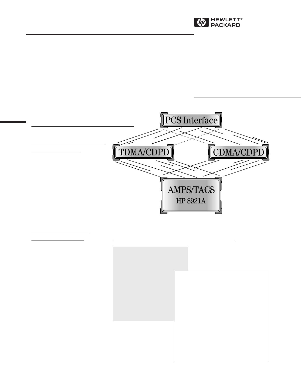
The HP 8921A Cell SiteTest Set Family
A Total Solution for Wireless
Infrastructure Test
The HP 8921A Cell Site Test Set
family has the flexibility needed
to meet analog and digital wireless
infrastructure test challenges.
Leveraging the performance of
the HP 8921A for new digital
technologies gives you a common
platform with the advantages of
user familiarity and low-cost
upgrades.
Build on the Strengths
of the HP 8921A. . .
• High performance measurement
capabilities to ensure thorough
testing.
• Built-in controller and automated measurements for standardized testing in less time.
• Common instrument base to
reduce technician training and
instrument pool needs.
• World-wide training and support
across all technologies to give
you a single contact for all your
technical questions.
. . .Adding Capabilities as Your System Grows!
• AMPS / NAMPS
• TACS / ETACS / UTACS
• TDMA
• CDMA
• CDPD
• PCS
Table of Contents Pages
Analog Specifications, HP 8921A ............... 3 - 5
TDMA Specifications, HP 83204A ................... 6
CDMA Specifications, HP 83205A ............. 6 - 8
CDPD Specifications, HP 83204/5A ................8
PCS Specifications, HP 83236B ...................... 9
Common Specifications .................................. 10
Software, HP 11807B ........................... 11 - 15
Front and Rear Panel Drawings ................ 16-18
Video and Literature Ordering Info .................. 19
Page 2

HP 8921A Cell Site Test Set Family
AMPS/NAMPS/TACS/ETACS/UTACS —
HP 8921A, HP 11807B
Install and maintain AMPS, NAMPS, TACS, ETACS,
and UTACS cell site radio equipment with the
HP 8921A Cell Site Test Set and the HP 11807B Cell
Site Test Software.
CDMA — HP 8921A Option 600
(HP 8921A + HP 83205A Option 001)
Test IS-95A/97A base stations with the HP 8921A
Option 600 CDMA Cell Site Test System. This system
consists of an HP 8921A Cell Site Test Set and the
HP 83205A CDMA Cellular Adapter. Existing
HP 8921As can be upgraded for CDMA digital testing
by adding the HP 83205A. (Older HP 8921As require
the Option G21 upgrade for complete CDMA capabilities.) The HP 8921A retains its full capabilities for
testing AMPS/NAMPS base stations.
The HP 8921A+11807B test solution uses the
HP 8921A’s built-in IBASIC controller to fully
automate base station test procedures with the
HP 11807B Software Test packages.
Developed from manufacturer’s recommended
maintenance procedures, the HP 11807B Cell Site
Test Software ensures complete test and adjustment
of cell sites as recommended by the manufacturers.
By using the standardized maintenance procedures,
each cell site receives the same high-quality analysis
and adjustment.
Coverage for Analog and Digital
Cellular Systems
Besides testing AMPS and TACS base stations, the
HP 8921A is ready to grow with your measurement
needs for future cellular systems.
TDMA — HP 8921A Option 500
(HP 8921A + HP 83204A Option 001)
The HP 83204A TDMA Cellular Adapter adds a
complete π/4 DQPSK signal generator, modulation
analyzer, and BER analyzer to the HP 8921A while
maintaining all analog measurements for dual-mode
testing of IS-136 digital cellular formats. HP 11807B
software fully automates TDMA test procedures
recommended by manufacturers to optimize system
performance.
CDPD — HP 8921A + HP 83204A or HP 83205A
The HP 8921A has optional Cellular Digital Packet
Data (CDPD) test capability for installing and maintaining CDPD Mobile Data Base Station (MDBS) RF
infrastructure equipment. CDPD capability can be
ordered with TDMA, CDMA, or analog test systems;
or CDPD test features can be retrofit to existing
HP 8921As.
PCS — HP 83236B
HP 8921A PCS solutions build on the HP 8921A
cellular band test solutions for TDMA and CDMA—
adding the HP 83236B PCS Interface to extend testing
capabilities to U.S. and international PCS frequencies
(1710 to 1990 MHz). Contact your local HewlettPackard sales representative for PCS solutions at
other frequencies. The HP 83236B can be combined
with existing HP 8921A systems without returning
them to the factory.
PCS TDMA — HP 8921A Option 501
(HP 8921A + HP 83204A Option 001 + HP 83236B)
The HP 83236B provides the capabilities of the
TDMA Option (Option 500) at PCS frequency bands
(1710-1990 MHz).
PCS CDMA — HP 8921A Option 601
(HP 8921A + HP 83205A Option 001+ HP 83236B)
The HP 83236B provides the capabilities of the
CDMA Option (Option 600) at PCS frequency bands
(1710 - 1990 MHz).
Literature
• “HP 8921A Cell Site Test Set, HP 11807B Cell Site
Test Software, HP 83204A TDMA Cellular
Adapter, HP 83205A CDMA Cellular Adapter,
HP 83236B PCS Interface”:
- Brochure: — p/n 5965-1579E
- Configuration Guide: — p/n 5965-7061E
- Price List: — p/n 5965-7063EUS
• “HP 8921A/11807B Option 120 AMPS Call Analysis,
Logging and Monitoring Software” Product
Overview — p/n 5963-6891EUS
2
• “HP 83236B PCS Interface” Product Overview
— p/n 5964-9655E
• “HP 83224A IBASIC Developers Tool Kit for RF
Communication Test Sets” Product Overview
— p/n 5964-3897E
• “HP 8921A Cell Site Test Set for AMPS Base Station
Testing” Product Note 8921-1 — p/n 5962-9475E
• “HP 8921A Cell Site Test Set for TACS Base Station
Testing” Product Note 8921-2 — p/n 5962-0157E
Page 3

Analog Specifications - HP 8921A
Specifications describe the instrument’s warranted performance after a 30minute warm up period and are valid over the entire operating and environmental
range unless otherwise noted.
Supplemental Characteristics are intended to provide additional information
useful in applying the instrument by giving typical, but non-warranted
performance para-meters. These are shown in italics or labeled as “typical”,
“usable to”, or “nominal”.
FM Rate (1 kHz reference):
Internal: DC to 25 kHz (1 dB BW)
External AC Coupled: 20 Hz to 75 kHz (typical 3 dB BW)
External DC Coupled: DC to 75 kHz (typical 3 dB BW)
FM Accuracy (1 kHz rate):
≤10 kHz dev: ±3.5% of setting ±50 Hz
>10 kHz dev: ±3.5% of setting ±500 Hz
FM Distortion (THD+Noise, 0.3 to 3 kHz BW):
<0.5% at >4 kHz deviation and 1 kHz rate
Center Frequency Accuracy in DC FM Mode
(external source impedance <1k Ω):
±500 Hz (after DCFM zero), typically ±50 Hz
ANALOG
Signal Generator
RF Frequency
Range: 250 kHz to 1000 MHz
Accuracy and Stability: same as reference oscillator ±0.015 Hz
Switching Speed: <150 ms to be within 100 Hz of carrier
frequency
Resolution: 1 Hz
Output
RF In/Out Connector
Level Range: −137 to −19 dBm into 50 Ω
Level Accuracy: ±1.8 dB (level ≥−127 dBm)
Typically ±1.0 dB for all levels
Reverse Power: 60 watts continuous
100 watts for 10 seconds per minute
SWR: <1.5:1
Duplex Out Connector
Level Range: −127 to +7 dBm into 50 Ω
Level Accuracy: ±1.5 dB,
Typically ±1.0 dB for all levels
Reverse Power: 200 mW maximum
SWR: <2.0:1 (level <−4 dBm)
Ext. Mod Input Impedance: 600 W nominal
Resolution: 50 Hz for <10 kHz deviation
500 Hz for ≥10 kHz deviation
Audio Source
(Both internal sources)
Frequency
Range: dc to 25 kHz
Accuracy: 0.025% of setting
Resolution: 0.1 Hz
Output Level
Range: 0.1 mV to 4 Vrms
Maximum Output Current: 20 mA peak
Output Impedance: <1 Ω (at 1 kHz)
Accuracy: ±2% of setting plus resolution
Residual Distortion (THD+Noise, level ≥ 200 mVrms):
<0.125%; 20 Hz to 25 kHz in an 80 kHz BW
Resolution: Level £ .01 V: ±50 µV
Level £ 0.1 V: ±0.5 mV
Level £ 1 V: ±5 mV
Level >1 V: ±50 mV
Offset in DC Coupled Mode: <50 mV
Resolution: 0.1 dB
Spectral Purity
Spurious Signals (for ≤ +1 dBm output level at
Duplex Out or ≤−25 dBm output level at RF In/Out):
Harmonics: <−30 dBc
Non-Harmonic Spurious: <−60 dBc (at >5 kHz
offset from carrier)
Residual FM (CCITT, rms):
<7 Hz for 250 kHz ≤fc ≤1000 MHz
<4 Hz for 249 MHz ≤fc ≤501 MHz
SSB Phase Noise: <−110 dBc/Hz (for >20 kHz offsets
at a 500 MHz carrier frequency)
FM
FM Deviation (rates >25 Hz):
100 kHz; 100 kHz ≤fc <249 MHz
50 kHz; 249 MHz ≤fc <501 MHz
100 kHz; 501 MHz ≤fc <1000 MHz
(FM not specified for (fc minus FM dev.) <250 kHz)
RF Analyzer
RF Frequency Measurement
Measurement Range: 400 kHz to 1000 MHz
Level Range:
RF In/Out: 1 mW to 60 W continuous
100 W for 10 seconds per minute
Ant In: -36 dBm to +20 dBm
Accuracy: ±1 Hz plus timebase accuracy
Resolution: 1 Hz
RF Power Measurement
Frequency Range: 30 MHz to 1000 MHz
Measurement Range:
RF In/Out: 1 mW to 60 W continuous
100 W for 10 seconds per minute
Accuracy: ±5% of reading ±0.01 mW (at 25°C±10°C)
±10% over full temperature range
SWR: <1.5:1
Resolution: Power <10 W: 1 mW
Power ³10 W: 10 mW
3
Page 4

ANALOG
Analog Specifications - HP 8921A
Continued
RF Analyzer Continued
FM Measurement
Frequency Range: 5 to 1000 MHz (usable to 400 kHz)
Deviation Range: 20 Hz to 75 kHz
Sensitivity (30 kHz IF BW; high sensitivity mode,
0.3 to 3 kHz BW): 2 µV (12 dB SINAD, fc ≥10 MHz)
Typically <1 µV
Accuracy (20 Hz to 25 kHz rates, deviation ≤25 kHz): ±4% of
reading plus residual FM and noise contribution
Bandwidth (3 dB): 2 Hz to 70 kHz
(DCFM measurements also available)
THD+Noise: <1% for ≥5 kHz deviation and 1 kHz rate in a 0.3
to 3 kHz BW
Input Level Range for Specified Accuracy:
−18 to +50 dBm at RF In/Out (0.04 mW to 100 W)
−54 to +14 dBm at Ant In
Residual FM and Noise (0.3 to 3 kHz, rms): <10 Hz
Resolution: Deviation <10 kHz: 1 Hz
Deviation ³10 kHz: 10 Hz
Spectrum Analyzer
Frequency Range: 400 kHz to 1000 MHz
Frequency Span/Resolution Bandwidth (coupled):
Span Bandwidth
<50 kHz 300 Hz
<200 kHz 1 kHz
<1.5 MHz 3 kHz
<18 MHz 30 kHz
≥ 18 MHz 300 kHz, Plus full span capability
Display: Log with 1, 2, and 10 dB/div
Display Range: 80 dB
Reference Level Range: +50 to −50 dBm
Residual Responses: <−70 dBm (no input signal, 0 dB attenuation)
Image Rejection: >50 dB
Non-harmonic Spurious Responses: >70 dB down (for input
signals <-30 dBm)
Level Accuracy: ±2.5 dB
Displayed Average Noise Level: <−114 dBm for <50 kHz spans
Log Scale Linearity: ±2 dB (for input levels ≤−30 dBm and/or
60 dB range)
Other Features: Peak hold, marker with frequency and level readout,
marker to peak, marker to next peak, trace comparison A-B,
trace averaging
Tracking Generator
Frequency Range: 400 kHz to 1000 MHz
Frequency Offset: Frequency span endpoints ± frequency offset
cannot be <400 kHz or ≥1000 MHz
Output Level Range: Same as signal generator
Sweep Modes: Normal and inverted
Other Features: Normalize
4
Adjacent Channel Power
Relative Measurements
Level Range:
Ant In: −40 dBm to +20 dBm
RF In/Out: 0.16 mW (−8 dBm) to 60 W (47.8 dBm)
continuous; or up to 100 W (50 dBm) for 10 seconds
per minute
Dynamic Range: Typical values for channel offsets
Channel Offset Channel BW Dynamic Range
12.5 kHz 8.5 kHz −65 dBc
20 kHz 14 kHz −68 dBc
25 kHz 16 kHz −68 dBc
30 kHz 16 kHz −68 dBc
60 kHz 30 kHz −65 dBc
Relative Accuracy: ±2.0 dB
Absolute Level Measurements
Level: Results of absolute power in watts or dBm are met by
adding the adjacent channel power ratio from the
spectrum analyzer to the carrier power from the input
section RF power detector
Level Range
Ant In: N/A
RF In/Out: 1 mW (0 dBm) to 60 W (47.8 dBm) continuous; or
up to 100 W (50 dBm) for 10 seconds per minute
Dynamic Range: Typical values for channel offsets
Channel Offset Channel BW Dynamic Range
12.5 kHz 8.5 kHz -65 dBc
20 kHz 14 kHz -68 dBc
25 kHz 16 kHz -68 dBc
30 kHz 16 kHz -68 dBc
60 Hz 30 kHz -65 dBc
Absolute Accuracy: Equals the sum of RF power measurement
accuracy found in the RF analyzer section and the adjacent
channel power relative accuracy of ±2.0 dB
AF Analyzer
Frequency Measurement
Measurement Range: 20 Hz to 400 kHz
Accuracy: ±0.02% plus resolution plus reference oscillator accuracy
External Input: 20 mV to 30 Vrms
Resolution: f <10 kHz: 0.01 Hz
f <100 kHz: 0.1 Hz
f ³100 kHz: 1 Hz
AC Voltage Measurement
Measurement Range: 0 to 30 Vrms
Accuracy (20 Hz to 15 kHz, inputs ≥1 mV): ±3% of reading
Residual THD+Noise (15 kHz BW): 150 µV
3 dB Bandwidth: Typically 2 Hz to 100 kHz
Nominal Input Impedance: 1M W in parallel with 76 pF or 600 W
floating
Resolution: 4 digits for inputs ³100 mV
3 digits for inputs <100 mV
Page 5

Analog Specifications - HP 8921A
Continued
AF Analyzer Continued
DC Voltage Measurement
Voltage Range: 100 mV to 42 V
Accuracy: ±1.0% of reading plus DC offset
DC Offset: ±45 mV
Resolution: 1 mV
Signaling
Capability for Generating and Analyzing the Following Formats:
CDCSS, DTMF, 1 Tone, 2 Tone, 5/6 Tone, Sequential, RPC1
(POCSAG), EIA, CCITT, CCIR, ZVEI, DZVEI, GOLAY, EEA,
AMPS, NAMPS, TACS, NTACS, NMT-450, NMT-900, LTR,
EDACS, MPT 1327
Function Generator Waveforms: Sine, square, ramp, triangle, dc,
White Gaussian and White Uniform noise
Function Generator Frequency Range and Level: Same as audio
source
DC Current Meter Specifications
ANALOG
Distortion/SINAD Measurement
Fundamental Frequency: 1 kHz ±5 Hz
Input Level Range: 30 mV to 30 Vrms
Display Range: 0.1% to 100% for distortion mode,
0 to 60 dB for SINAD mode
Accuracy: ±1 dB (0.5 to 100% distortion, 0 to 46 dB SINAD)
Residual THD+Noise (15 kHz BW): −60 dB or 150 µV,
whichever is greater
Resolution: 0.01% distortion or 0.01 dB SINAD
Audio Filters
High-Pass Filters: <20 Hz, 50 Hz, and 300 Hz
Low-Pass Filters: 300 Hz, 3 kHz, 15 kHz, >99 kHz
Other Filters: 750 µs De-emphasis, 1 kHz Notch Filter, C-Message
Weighting Filter and 6 kHz Bandpass Filter
Optional Filter: CCITT Weighting Filter (Option 011) can be
substituted for C-Message Weighting Filter
Audio Detectors
RMS, RMS SQRT2, Pk+, Pk-, Pk+hold, Pk−hold, Pk±/2,
*
Pk±/2hold, Pk±max, Pk±maxhold
Oscilloscope
Frequency Range (3 dB): 2 Hz to 50 kHz
Scale/Division: 10 mV to 10 V
Amplitude Accuracy (20 Hz to 10 kHz): ±1.5% of reading ±0.1 div.
Time/Division: 1 µs to 200 ms
3 dB Bandwidth: Typically >100 kHz
Internal DC Offset: £ 0.1 div. (³ 50 µV/div. sensitivity)
Measurement Range: 0 to 10A (usable to 20A)
Accuracy: ±10% of reading after zeroing (levels >100 mA)
Remote Programming
HP-IB: Hewlett-Packard's implementation of IEEE Standard 488.2
Functions Implemented: SH1, AH1, T6, L4, SR1, RL1, LE0, TE0,
PP0, DC1, DT1, C4, C11, E2
RS-232: 6-wire RJ-11 connector provides two 3-wire serial ports
for serial data in and out, no hardware handshake capability
Baud Rates: 300, 600, 1200, 2400, 4800, 9600, and 19200
selectable
Parallel Interface is provided for output to a printer
Reference Oscillator
Temperature: 0.05 ppm (0 to +55°C)
Aging: <0.5 ppm/year (<1 ppm in first year)
Warm Up Time: <15 minutes to be within ±0.1 ppm of
final frequency
Rear Panel BNC Connectors:
Input Frequency: 1, 2, 5, 10 MHz
Input Level: >0.15 Vrms
Output Frequency: 10 MHz
Output Level: >0.5 Vrms
Save and Recall Registers
Available RAM: Approximately 640 kBytes of RAM are available
for save/recall of instrument settings or IBASIC programs.
This typically will hold hundreds of sets of instrument settings
depending on the type of information saved and the size of any
IBASIC programs used. When running the HP 11807B cell site
test software, approximately 256 Kbytes of RAM are available
for save/recall use.
5
Page 6

TDMA Specifications -
HP 8921A Option 500 or 503
(HP 8921A with HP 83204A Option 001 or 003)
CDMA Specifications -
HP 8921A Option 600 or 603
(HP 8921A with HP 83205A Option 001 or 003)
TDMA Signal Generator
Frequency Range: 824 MHz to 894 MHz
Output Level Range:
TDMA CDMA
Residual Error Vector Magnitude: <3.0%
Residual Phase Error: <3 °
Residual Magnitude Error: <3.0%
IQ Origin Offset: < -30 dBc within ±15 °C of the temperature
Frequency Error: ±4 Hz plus reference
TDMA Analyzer
Frequency Range: 824 MHz to 894 MHz
Input Level Range:
Input Frequency Setting Error: 1 kHz
RX DSP Level Setting Range: 0 dB to −23 dB full scale
Residual Error Vector Magnitude: <2.0%
Error Vector Magnitude Measurement Accuracy: 0.4% +2%
Residual Phase Error: <1.5 °
Residual Magnitude Error: <1.4%
I/Q Origin Offset Accuracy: ±0.5 dB for values to −40 dBc
Frequency Error Accuracy: ±2 Hz plus reference
RF In/Out: −22 dBm to −127 dBm
Duplex Out: +4 dBm to −127 dBm
at the last calibration
RF In/Out: 1 mW to 60 W (0 to +47.78 dBm)
Ant In: −36 dBm to +17 dBm
of reading
CDMA Signal Generator
Frequency/Amplitude
Frequency Range: 824 to 894 MHz usable from 800 MHz to
1000 MHz and from 4 MHz to 200 MHz with degraded rho (r)
and carrier feedthrough performance.
Frequency Resolution: 1 Hz
Output Level Range:
RF In/Out: −19 dBm to −137 dBm
Duplex Out: +4 dBm to −127 dBm
Output Level Accuracy:
RF In/Out: ±2.0 dB, typically ±1.0 dB
Duplex Out: ±1.7 dB, typically ±1.0 dB
Modulation
Reverse Link Source Modulation: OQPSK per TIA IS-95
Reverse Link Source Modulation Data1: Internal data buffer, Idle
(all zeroes)
Forward Link Source Modulation: QPSK per TIA IS-95
Forward Link Source Modulation Data1: Internal (Pilot channel)
Residual Rho (r): Better than 0.96 typically >0.98
Carrier Feedthrough: Typically <-35 dBc
Adjacent Channel Noise: Typically <−50 dBc
measured in a 30 kHz BW filter relative to the total carrier
power at f
In/Out connector (<−3 dBm when using the Duplex Out
connector)
PN Offset: Adjustable from 0 to 511 units (1 unit equals 64 chips)
PN Offset Resolution: 0.0156 units (1 chip)
±900 kHz for output levels <−29 dBm at the RF
c
Data Buffer
Size/Length: 5400 frames
Modes: Single, Continuous Looping, and Idle
Coding: IS-95 CDMA full rate reverse link channel coding,
interleaving and spreading
Long Code Mask: 42 zeros
Input Data Rate: 9600 bps; 14,400 bps
Data Source: For each rate set, 300 frames factory loaded, 1800
frames additional user definable data can be entered via HP-IB
1 May also be modulated with external encoded data. External data must be
properly coded and ready for short sequence spreading at 1.2288 Mbit per
second.
6
Page 7

CDMA Specifications -
HP 8921A Option 600 or 603
Continued
CDMA Signal Generator Continued
AWGN Source
(Added White Gaussian Noise)
Bandwidth: 2 MHz nominally, Gaussian to >3 sigma
Modes: Noise only, data only, and user selectable Eb/No settings
Eb/No Resolution: 0.1 dB
Eb/N
Range: −5 to 25 dB
o
Eb/No Accuracy: ±0.5 dB, for Eb/No of 5 to 20 dB, typically ±1 dB,
for Eb/N
of −5 to +5 dB and +20 dB to +25 dB
o
Average Power Measurement
Input Frequency Range: 30 MHz to 1000 MHz
Input Connector: RF In/Out
Measurement Bandwidth: Provides an accurate measure of the
total power for signals within 2 MHz of the operating
frequency. If other signals are present outside this frequency
range, reduced measurement accuracy will result.
Maximum Input Level: 60 W continuous
Measurement Range: 1 mW to 60 W (0 to +48 dBm)
Measurement Accuracy
Measurement Period: 0.25 ms to 5 ms
3
:±5% ±1 µW, at 25°C ±10°C
±10% ±1 µW, from 0° to 55°C
Channel Power Measurement
Input Frequency Range: 4 MHz to 1000 MHz
Input Connector: RF In/Out (usable on Ant In with reduced
measurement accuracy)
CDMA Analyzer
Waveform Quality Measurement Rho (r)
IS-95 forward or reverse link formats (QPSK or OQPSK)
Input Frequency Range: 4 MHz to 1000 MHz
Input Level Range:
RF In/Out: −10 dBm to +48 dBm
Ant In: −46 dBm to +17 dBm
Rho (r) Measurement Interval Range: 0.25 to 1.25 ms
Rho (r) Measurement Range: 0.50 to 1.00
Rho (r) Measurement Accuracy: <±0.005
Input Frequency Error Range: ±900 Hz
Frequency Error Measurement Accuracy2: ±30 Hz using a
measurement interval ≥ 0.5 ms
Other Reported Parameters: Pilot Time Offset, Carrier
Feedthrough, Error Vector Magnitude, Amplitude Error and
Phase Error
Pilot Time Offset Measurement Accuracy: Typically <±500 ns
from even-second signal to start of PN sequence
Measurement Bandwidth: Measures the total power in a
1.23 MHz bandwidth centered on the selected frequency
Measurement Range: −10 dBm to +48 dBm
Measurement Accuracy3: ±1 dB over a range of ±5°C from the
temperature at the last calibration
Code Domain Analyzer
Code Domain Power Measurement
Input Frequency Range: 4 MHz to 1000 MHz
Input Connector: RF In/Out or Ant In
Input Frequency Error Range: ±900 Hz
Input Level Range:
RF In/Out: −10 dBm to +48 dBm
Ant In: −46 dBm to +17 dBm
Measurement Dynamic Range: 40 dB
Measurement Accuracy: ±0.5 dB using a measurement interval
≥0.5 ms
Measurement Resolution: 0.01 dB
Carrier Frequency Offset Accuracy2: ±30 Hz using a
measurement interval ≥0.5 ms
CDMA
2 Accuracy can be improved by averaging a number of measurements. Error is
reduced by the square root of the number of averages.
3 When measuring power at the RF In/Out port, the internal signal generator's
level must be 60 dB below the measured power or less than −20 dBm at the
Duplex Out port.
Pilot Time Offset Measurement Accuracy: Typically <500 ns
from even-second signal to start of PN sequence
Code Domain Timing Measurement
(Pilot to Code Channel Time Tolerance)
Input Frequency Range: 4 MHz to 1000 MHz
Input Connector: RF In/Out or Ant In
Input Frequency Error Range: ±900 Hz
7
Page 8

CDMA Specifications-
HP 8921A Option 600 or 603
Continued
Code Domain Analyzer Continued
Input Level Range:
RF In/Out: −10 dBm to +48 dBm
Ant In: −46 dBm to +17 dBm
Measurement Range: ±4 ns to ±200 ns
Measurement Accuracy: ±10 ns using a measurement interval of
1.25 ms and ≥10 averages
Measurement Resolution: 0.01 ns
Even Second Sync Input: (BNC) accepts a rising edge to reset the
internal short sequences and CDMA clocks. Periodic inputs
should have a period of 2 seconds and a minimum pulse
width of >50 ns
Input Level: ≥0 dBm (into 50 Ω)
Outputs:
Coaxial BNCs:
19.6608 MHz (TTL levels)
1.2288 MHz (TTL levels)
TTL Sub Min D:
20 ms frame clock
26.67 ms short sequence clock
80 ms clock
Every even second
CDPD Specifications -
Code Domain Phase Measurement
(Pilot to Code Channel Phase Tolerance)
Input Frequency Range: 1 MHz to 1000 MHz
CDMA
Input Connector: RF In/Out or Ant In
Input Frequency Error Range: ±900 Hz
Input Level Range:
Measurement Range: ±4 mrad to ±200 mrad
Measurement Accuracy: ±20 mrad using a measurement interval
Measurement Resolution: 10 mrad
CDPD
RF Time Base
(For proper operation, this reference must be locked to a high-quality
external reference)
Locking Range: ±10 ppm
Input Frequencies: 19.6608 MHz, 15 MHz, 10 MHz, 9.8304 MHz,
Input Level: ≥ 0 dBm (into 50 Ω)
Output Frequency: 10 MHz
Output Level: TTL
CDMA Reference
(For proper operation, this reference must be locked to the internal RF
timebase or a high-quality external reference)
Locking Range: ±10 ppm
Input Frequencies: 19.6608 MHz, 15 MHz, 10 MHz, 9.8304 MHz,
8
RF In/Out: −10 dBm to +48 dBm
Ant In: −46 dBm to +17 dBm
of 1.25 ms and ≥10 averages
5 MHz, 4.9152 MHz, 2.4576 MHz, 1.2288 MHz, and 1 MHz
5 MHz, 4.9152 MHz, 2.4576 MHz, 1.2288 MHz, and 1 MHz
HP 83204A, HP 83205A
Specifications apply to HP 8921A when fitted with HP 83204A Option
002 or 003 or HP 83205A Option 002 or 003 cellular adapters and
when running the provided CDPD MDBS cell site test software.
(Software is included with each of these cellular adapters.)
CDPD Signal Generator (at HP 8921A Duplex Out)
Output:
Level Range and Level Accuracy: Same as HP 8921A
Reverse Power: Same as HP 8921A
Frequency Range: Same as HP 8921A
Frequency Accuracy: ±500Hz, typically ±50Hz
Spectral Purity:
Spurious Signals, Adjacent Channels: <−26 dBc
Spurious Signals, First Alternate Channel: <−45 dBc
Spurious Signals, Second Alternate Channel: <—60 dBc
Switching Speed: Typically <150 ms to be within 1 kHz
Transmitter On/Off Level and Timing: >15 dB down in <1ms
Modulation Type: GMSK with BT=0.5
Modulation Accuracy: <5% error in modulation index
CDPD Analyzer
RF Frequency Range: Same as HP 8921A
Input Level Range: Same as HP 8921A
RF Power Measurement:
Accuracy: RF In/Out: 5%, ±0.01 mW (at 25°±10°C) for
single signal >200 mw, 10% over full temperature range
Frequency Error Accuracy: Time base accuracy ±1 Hz
Modulation Index Accuracy: <0.1% error in modulation index
Adjacent Channel Power measurement floor: Typically −45 dBc
Alternate and Second Alternate Channel Power measurement
noise floor
4 For RF input signal levels >–38 dBm.
4
: Typically −60 dBc
Page 9

PCS Interface Specifications -
HP 83236B
PCS specifications apply to HP 83236B operation with continuous
wave signals
Generator Output Path
(RF In/Out and RF Out Only connector)
Frequency
Frequency Range:
Through Path: 800 to 849 MHz
869 to 960 MHz
Conversion Path: 1710 to 1785 MHz
1805 to 1910 MHz
1930 to 1990 MHz
Frequency Settling Time: <10 ms
Output
RF In/Out Connector:
Output Level Range: −130 dBm to − 20 dBm
RF Out Only Connector:
Output Level Range: −130 to −10 dBm
Level Accuracy:
±1.8 dB, at 23°C ±10°C
±2.0 dB, at 0°C to 55°C
Typically ± 1.0 dB, at 0°C to 55°C
Output Level Settling Time: <80 ms
Spectral Purity
6
5
Analyzer Input Path (RF In/Out connector)
Frequency
Frequency Range:
Through Path: 800 to 960 MHz
Conversion Path: 1710 to 1785 MHz
1805 to 1910 MHz
1930 to 1990 MHz
Max Input Level: The maximum allowable average power
depends on the unit under test as follows:
Single Carrier TDMA and FM: 40 dBm (10 W)
CDMA Subscriber Unit: 37 dBm (5 W)
CDMA Base Station: 30 dBm (1 W)
Maximum Peak Instantaneous Signal: 30 V
Spectral Purity
Integrated Spurious and Phase Noise:
<-57 dBc in a 100 Hz to 32 kHz bandwidth
Spurious Level: <-60 dBc at ³5 kHz and ≤20 MHz offset from carrier
Power Measurement
Frequency Range: 800 to 960 MHz
1710 to 1785 MHz
1805 to 1910 MHz
1930 to 1990 MHz
Measurement Range:
Single Carrier TDMA and FM: −13 dBm to 40 dBm (50 µW to 10 W)
CDMA and Multi-carrier:
Subscriber Unit: −13 dBm to 37 dBm (50 µW to 5 W)
Base Station: −13 dBm to 30 dBm (50 µW to 1 W)
Accuracy: ±5% ±2.5 µW
±10 % ±2.5 µW
Resolution: 0.01 dB or 10 µW
7
Type of
spurious
Harmonic
Non-Harmonic
SSB Phase Noise: <−100 dBc/Hz at 20 kHz offset from carrier
5 To meet generator output path specifications, the input signal must
be from an HP 8921A/D RF test set with the following characteristics;
Input Frequency Range: 800 MHz to 995 MHz and
Input Level Range: –70 dBm to –7 dBm.
6 HP 83236B only.
7 At 23°C ±10°C after power meter zero and calibration.
800 to 960 960 to 1710 1710 to 1990
<
–30 dBc – <–30 dBc
<
–60 dBc* <–25 dBc** <–60 dBc*
*Offsets >5 kHz **For carrier levels >–100 dBm
Frequency (MHz)
Reference Specifications
For proper operation, this instrument must be locked to an external
10 MHz reference
Input Frequency: 10 MHz
Input Level Range: −5 dBm to +10 dBm
Input Impedance: 50 Ω
Connector Type: BNC (F)
Remote Control
HP-IB: Hewlett-Packard’s implementation of IEEE Standard 488.2
Serial Port: Connector Type: D-SUB15 (F)
Interface: RS-232 C
General Specifications
Isolation Between “RF In/Out” and “RF Out Only”: >40 dB
Operating Temperature: 0 to 55°C
Non-operating Temperature: −55 to +70°C
Calibration Interval: Two years
PCS
9
Page 10

Common Specifications
Common Specifications
Dimensions:
(HxWxD)
HP 8921A: 188 x 330 x 456 mm (7.4 x 13 x 18 inches)
HP 83204A: 62 x 330 x 456 mm (2.4 x 13 x 18 inches)
HP 83205A: 62 x 330 x 456 mm (2.4 x 13 x 18 inches)
HP 83236B: 84 x 340 x 500 mm (3.4 x 13 x 19 inches)
HP 8921A Opt. 500, 502, 503:
250 x 330 x 456 mm (9.8 x 13 x 18 inches)
HP 8921A Opt. 600, 602, 603:
250 x 330 x 456 mm (9.8 x 13 x 18 inches)
Weight:
HP 8921A: 17.27 kg. (38 lbs.) net
29.55 kg. (65 lbs.) shipping
HP 83204A: 6.36 kg. (14 lbs.) net
11.36 kg. (25 lbs.) shipping
HP 83205A: 6.36 kg. (14 lbs.) net
11.36 kg. (25 lbs.) shipping
HP 83236B: 5.6 kg. (12 lbs.) net
7.9 kg. (17 lbs.) shipping
HP 8921A Opt. 500, 502, 503:
23.18 kg. (51 lbs.) net
38.64 kg. (85 lbs.) shipping
Power:
HP 8921A: AC: 100 V to 240 V; 48 to 440 Hz; nominally 100 watts
DC: 11 to 28 V; nominally 120 watts
HP 83204A: AC: 100 to 240 V, 48 to 440 Hz; 120 VA max
HP 83205A: AC: 100 to 240 V, 48 to 440 Hz; 120 VA max
HP 83236B: AC: 115 to 230 V, 50/60 Hz; 100 VA max
HP 8921A Opt. 500:
AC: 100 to 240 V, 48 to 440 Hz, nominally 140 watts
HP 8921A Opt. 600:
AC: 100 to 240 V; 48 to 440 Hz, nominally 140 watts
Miscellaneous:
HP 8921A CRT Size: 7 x 10 cm
Operating Temperature: 0 to +55°C
Storage Temperature: −55 to +75°C
Calibration Interval: Two years
Leakage: Conducted and radiated interference meets CISPR 11.
Typical HP 8921A radiated leakage at signal generator output
frequency is <1.0 µV (2.0 µV for HP 8921 Options 500 or
600) induced in a resonant dipole antenna 25 mm (1 inch)
from any surface except the rear panel for RF output levels
<−40 dBm. Spurious leakage levels are typically <1 µV in a
resonant dipole antenna.
HP 8921A Opt. 600, 602, 603:
23.18 kg. (51 lbs.) net
38.64 kg. (85 lbs.) shipping
10
Page 11

HP 11807B Cell Site Test Software
Specifications
SOFTWARE
Option 040 Motorola AMPS, NAMPS Test Software
Models Tested: HDII, HDII (NAMPS), LD
• RS-232 Interface to Base Station
Tests Performed:
• URDM or RDM Frequency and Level
• Voice Transceiver
Receiver
Audio Output
SINAD for each antenna
Audio Distortion
Hum and Noise
Expander Response
Audio Response
Signal and No Signal SAT/DSAT
Signal and No Signal ST/DST Detect
Transmitter
Frequency Error
Power at Level 0
SAT Frequency Error
SAT/DSAT Peak Deviation
JK Output
Peak Voice Limiting
Voice Deviation
Audio Distortion
Hum and Noise
Compandor Track Error
Audio Frequency Response
Peak Data Deviation
• Signaling Transceiver Manual Mode
Frequency Error
Power
Data Deviation
SINAD
SSI Calibration and Linearity
Option 041 General Electric AMPS Test Software
Models Tested: G.E. RCU, Compact RCU
• RS-232 Interface to RCU
Tests Performed:
• Transmitter Tests
RF Power
RF Frequency Error
SAT Modulation
Data Modulation
Voice Deviation Limiting
Audio Frequency Response
Audio Distortion
Hum and Noise
Compandor Response
• Receiver Tests
Audio Line Output Level
RX1 and RX2 Audio Level
Audio Loopback
RX1 and RX2 Sensitivity
RX1 and RX2 RSSI
RX1 and RX2 SAT Detection
RX1 and RX2 ST Detection
RX1 and RX2 SAT and ST Falsing
RX1 and RX2 Audio Frequency Response
RX1 and RX2 Audio Distortion
RX1 and RX2 Hum and Noise
Expander
• RF Measurement Tools
Swept Frequency Insertion Loss
Swept Frequency Return Loss
Discrete AMPS Channel Return Loss Test
Cable Fault Test (Return Loss versus Distance)
PC Data Transfer
• Scanning Receiver Manual Mode
Scan Sensitivity for each Antenna
SAT/DSAT Detect
SSI Calibration and Linearity
• Combiner Adjustment
• Wideband Data
• Manual Switch and Calibration Aid
• Calculate Transmitter Power
• Voice Channel Manual Test Mode
11
Page 12

SOFTWARE
Option 042 Ericsson AMPS, and TDMA Test Software
Models Tested: Model 882, 882M (Microcell), 882D (DTRM),
882DM (DMTM)
• RS-232 Interface to Radio
Tests Performed:
• AMPS Transmitter Tests
Frequency Offset
Output Power
Audio Level Adjustments
Voice Deviation
Voice and SAT Deviation
Max. Voice Deviation
Data Deviation
SAT Tone Deviation
SAT Frequency Error
• TDMA Transmitter Tests
TDMA Power
TDMA Modulation Accuracy
- Error Vector Magnitude (EVM)
- Magnitude Error
- Phase Error
- Origin Offset
- Frequency Error
- Peak Error Vector Magnitude
TDMA Adjacent Channel Power
• AMPS Receiver Tests
Line Level
Sensitivity
Diversity Sensitivity
Squelch
Desense
RF Level Calibration
Loop Gain
SAT Detector
• TDMA Receiver Tests
TDMA RSSI
TDMA Sensitivity (BER)
• Combiner Alignment
Cavity Adjustment
Output Power to Antenna
• General Tests
Laptop Emulator
Memory Card Initialization
Local Control File Transfer
Internal Test DTRM/LVM
DTRM/DMTM Product Information
Calculate ERP
1
Option 043 AT&T AMPS, and TDMA Test Software
1
Lucent (formerly AT&T)
Models Tested: Autoplex Series II, LMT, Universal Microcell
• RS-232 Interface to MSC via External Modem
Tests Performed:
• Automated Frequency Plan Testing
AMPS Active and Growth Radios
TDMA Active and Growth Radios
Setup Radios
• AMPS FCC Transmitter Tests
Frequency Error
Output Power
Voice Deviation at −16 and 0 dBm
SAT Deviation
Data 10 kHz Deviation
Residual FM
Voice Distortion
SAT Frequency Error
• TDMA FCC Transmitter Tests
Frequency Error
Output Power
Error Vector Magnitude (including magnitude and phase error)
I/Q Origin Offset
Adjacent/Alternate Channel Power
• Setup Channel FCC Tests
Frequency Error
Output Power
Data 10 kHz Deviation
• Adjust Output Power
• Download/Diagnose Voice Channel
• Download/Diagnose Setup Channel
• RF Measurement Tools
Swept Frequency Gain Test
Swept Frequency Insertion Loss Test
Swept Frequency Return Loss Test
Discrete AMPS Channel Return Loss Test
Cable Fault Test (Return Loss versus Distance)
- Store and Retrieve Plots
- Plot Two Plots at Once
PC Data Transfer
• LMT/Universal Microcell Tests
12
• RF Measurement Tools
Swept Frequency Insertion Loss
Swept Frequency Return Loss
Discrete AMPS Channel Return Loss Test
Cable Fault Test (Return Loss versus Distance)
PC Data Transfer
1
Note: HP 11807B Options 040, 042, 043, 044, 045,
050, 052, 070, and 120, are for use with equipment
operating in the 800 MHz cellular bands.
Page 13

Option 044 Nortel AMPS, and TDMA Test Software
Option 045 -
1
Hughes AMPS Test Software
1
SOFTWARE
Models Tested: TRU/DRU and "P" series
• RS 232 Interface to Base Station
Tests Performed:
• Transmitter Tests
"P" Series and TRU/DRU Tests
Transmitter Quick Tests
Frequency Error
Maximum Power and Power Level
SAT Frequency and Deviation
Wideband Data Deviation
Residual FM
"P" Series Tests
Voice Modulation /Limiting / Adjustment
TRU/DRU Tests
TDMA Power
TDMA Adjacent Channel Power
Residual AM
Modulation Accuracy
- Error Vector Magnitude (EVM)
- Magnitude and Phase Error
- Origin Offset
- Frequency Error
- Peak Error Vector Magnitude
• Receiver Tests
"P" Series and TRU/DRU Tests
Receiver Quick Tests
Receiver A/B SINAD Sensitivity
Receiver A/B SAT Detection
Receiver A/B ST Detection
Receiver A/B Audio Level
Receiver A/B RSSI Linearity
Receiver A/B RSSI Offset
TRU/DRU Tests
RSSI/MC Gain Offset and Gain
Models Tested: Hughes GMH 2000 AMPS
Tests Performed:
• Transmitter Tests
Min/Max Output Power
Output Power
Frequency
Voice Deviation/Audio Level
SAT Frequency and Deviation
Maximum Voice Deviation
Spectrum Analyzer ATC Power and Intermodulation
Path Insertion Loss (for NGA)
• Receiver Tests
Sensitivity/SINAD
Deviation/Audio Level
RSSI
Path Gain
Path Insertion Loss
• Single Channel Amplifier Tests
Frequency Response and Min/Max
Frequency Response, Min/Max and Receiver
• RF Measurement Tools
Swept Frequency Insertion Loss
Swept Frequency Return Loss
Discrete AMPS Channel Return Loss Test
Cable Fault Test (Return Loss versus Distance)
PC Data Transfer
• General Tests
Laptop Emulator
Manual Switch Control
MPA LED Alarm and TRU/DRU Display
• RF Measurement Tools
Swept Frequency Insertion Loss
Swept Frequency Return Loss
Discrete AMPS Channel Return Loss Test
Cable Fault Test (Return Loss versus Distance)
PC Data Transfer
1
Note: HP 11807B Options 040, 042, 043, 044, 045,
050, 052, 070, and 120, are for use with equipment
operating in the 800 MHz cellular bands.
13
Page 14

SOFTWARE
Option 050 Motorola TACS, ETACS, UTACS, and
EUTACS Test Software
1
Option 052 Ericsson TACS, ETACS Test Software
1
• RS-232 Interface to Base Station
Tests Performed:
• RDM Frequency and Level
• Voice Transceiver
Receiver
Audio Output
SINAD for each antenna
Audio Distortion
Hum and Noise
Expander Response
Audio Response
Signal and No Signal SAT/DSAT
Signal and No Signal ST Detect
Transmitter
Frequency Error
Power at Level 0
SAT Frequency Error
SAT/DSAT Peak Deviation
JK Output
Peak Voice Limiting
Voice Deviation
Audio Distortion
Hum and Noise
Compandor Track Error
Audio Frequency Response
Peak Data Deviation
• Signaling Transceiver Manual Mode
Frequency Error
Power
Data Deviation
SINAD
SSI Calibration and Linearity
• Scanning Receiver Manual Mode
Scan Sensitivity for each Antenna
SAT/DSAT Detect
SSI Calibration and Linearity
• Combiner Adjustment
• Manual Switch and Calibration Aid
• Voice Channel Manual Test Mode
• Return Loss
VSWR Discrete and Swept Return Loss
VSWR versus Distance (cable fault location)
Models Tested: Model 883, 883M (Microcell)
• RS-232 Interface to Radio
Tests Performed:
• Transmitter Tests
Frequency Offset
Output Power
Audio Level Adjustments
Voice Deviation
Voice and SAT Deviation
Maximum Voice Deviation
Data Deviation
SAT Tone Deviation
SAT Frequency Error
• Receiver Tests
Line Level
Sensitivity
Diversity Sensitivity
Squelch
Desense
RF Level Calibration
Loop Gain
SAT Detector
• Combiner Alignment
Cavity Adjustment
Output Power to Antenna
• General Tests
Laptop Emulator
Memory Card Initialization
Local Control File Transfer
Calculator ERP
• RF Measurement Tools
Swept Frequency Insertion Loss
Swept Frequency Return Loss
Discrete AMPS Channel Return Loss Test
Cable Fault Test (Return Loss versus Distance)
PC Data Transfer
14
1
Note: HP 11807B Options 040, 042, 043, 044, 045,
050, 052, 070, and 120, are for use with equipment
operating in the 800 MHz cellular bands.
Page 15

Option 070 Motorola AMPS, NAMPS, Micro C
.I.T.
Test Software
Models Tested: AMPS/NAMPS, Micro C.I.T.E
• RS-232 Interface to Base Station
Tests Performed:
• URDM or RDM Frequency and Level
• Voice Transceiver Adjustment Manual Mode
• Voice Transceiver
Receiver
Audio Output
SINAD for each antenna
Audio Distortion
Hum and Noise
Expander Response
Audio Response
Signal and No Signal SAT/DSAT
Signal and No Signal ST/DST Detect
Transmitter
Frequency Error
Power at Level 0
SAT Frequency Error
SAT/DSAT Peak Deviation
Loopback Level
Peak Voice Limiting
Voice Deviation
Audio Distortion
Hum and Noise
Compressor Track Error
Audio Frequency Response
Peak Data Deviation
• Signaling Transceiver Manual Mode
Frequency Error
Power
Data Deviation
SINAD
SSI Calibration and Linearity
• Scanning Receiver Manual Mode
Scan Sensitivity for each antenna
SAT/DSAT Detect
SSI Calibration and Linearity
• Manual Switch and Calibration Aid
Option 083 -
E
Lucent CDMA PCS Test Software
Models Tested: Autoplex Series II PCS Minicell
• Automated Cell Site Configuration (using an RS-232
Interface to MSC via External Modem)
Tests Performed:
• CDMA PCS Transmitter Tests
Frequency Error
Output Power
Modulation Quality (rho)
Code Domain Power
Code Domain Timing
Code Domain Phase
Error Vector Magnitude, Magnitude Error, and Phase Error
Carrier Feedthrough
Output Power Monitoring/Adjustment
• CDMA Signal Analysis
Code Domain Analyzer
CDMA Analyzer
Spectrum Analyzer
• PN Offset Search
• Insertion Loss
SOFTWARE
Option 093 Lucent TDMA PCS Test Software
Models Tested: Autoplex Series II PCS Minicell
• Automated Cell Site Configuration (using an RS-232
Interface to MSC via External Modem)
Tests Performed:
• TDMA PCS Transmitter Tests
Frequency Error
Output Power
Error Vector Magnitude, Magnitude Error, and Phase Error
I/Q Origin Offset
Adjacent/Alternate Channel Power
VRAL Power and Power Control
• Adjust Output Power
• TDMA Signal Analysis
Spectrum Analyzer
• Insertion Loss Measurement
Option 120 - AMPS Call Analysis,
Logging, and Monitoring Software
• Voice Channel Manual Test Mode
• Return Loss
VSWR Discrete and Swept Return Loss
VSWR versus Distance (cable fault location)
Tests Performed:
• Find local AMPS control channels
• Display system information from forward control channel
• Count orders by type on forward control channel
• Display mobile identification numbers and orders on forward
control channel
• Follow call setups to voice channels and through subsequent
handoffs
• Display mobile data transmissions on reverse control channel
• Measure cell site transmitter performance off-the-air
• Measure mobile transmitter characteristics off-the-air
For details on software operation and capabilities refer to the
HP 11807B Option 120 Product Overview (p/n 5963-6891).
15
Page 16

HP 8921A Cell Site Test Set
FRONT AND REAR PANEL DRAWINGS
Front Panel
Rear Panel
16
Page 17

HP 83204A TDMA Cellular Adapter
Front Panel
Rear Panel
FRONT AND REAR PANEL DRAWINGS
HP 83205A CDMA Cellular Adapter
Front Panel
Rear Panel
17
Page 18

HP 83236B PCS Interface
FRONT AND REAR PANEL DRAWINGS
Front Panel
Rear Panel
B
18
Page 19

Additional Information
Videos
Call the HP 8921A Information Line 1-800-344-3802 to get
one of our free 40 minute videos showing AMPS/TACS/TDMA cell
site testing with the HP 8921A and HP 11807B.
• “Install and Maintain Lucent (AT&T) Cell Sites Fast”
- p/n 1000-1304E
• “Optimize Motorola Cell Sites Fast” - p/n 1000-1307E
• “Install and Maintain Ericsson Cell Sites Fast” - p/n 1000-1297E
Literature
• “HP 8921A Cell Site Test Set, HP 11807B Cell Site Test Software,
HP 83204A TDMA Cellular Adapter, HP 83205A CDMA Cellular
Adapter, HP 83236B PCS Interface”:
- Brochure: — p/n 5965-1579E
- Configuration Guide: — p/n 5965-7061E
- Price List: — p/n 5965-7063EUS
• “HP 8921A/11807B Option 120 Call Analysis, Logging and
Monitoring Software” Product Overview - p/n 5963-6891EUS
Additional Info
• “HP 83236B PCS Interface” Product Overview - p/n 5964-9655E
• “HP 83224A IBASIC Developers Tool Kit for RF Communication
Test Sets” Product Overview - p/n 5964-3897E
• “HP 8921A Cell Site Test Set for AMPS Base Station Testing”
Product Note 8921-1 - p/n 5962-9475E
• “HP 8921A Cell Site Test Set for TACS Base Station Testing”
Product Note 8921-2 − p/n 5962-0157E
19
Page 20

For more information about Hewlett-Packard
test & measurement products, applications,
services, and for a current sales office listing,
visit our web site, http://www.hp.com/go/tmdir.
You can also contact one of the following
centers and ask for a test and measurement
sales representative.
United States:
Hewlett-Packard Company
Test and Measurement Call Center
P.O. Box 4026
Englewood, CO 80155-4026
1 800 452 4844
Canada:
Hewlett-Packard Canada Ltd.
5150 Spectrum Way
Mississauga, Ontario
L4W 5G1
(905) 206 4725
Europe:
Hewlett-Packard
European Marketing Centre
P.O. Box 999
1180 AZ Amstelveen
The Netherlands
(31 20) 547 9900
Japan:
Hewlett-Packard Japan Ltd.
Measurement Assistance Center
9-1, Takakura-Cho, Hachioji-Shi,
Tokyo 192, Japan
Tel: (81-426) 56-7832
Fax: (81-426) 56-7840
Latin America:
Hewlett-Packard
Latin American Region Headquarters
5200 Blue Lagoon Drive
9th Floor
Miami, Florida 33126
U.S.A.
(305) 267 4245/4220
Australia/New Zealand:
Hewlett-Packard Australia Ltd.
31-41 Joseph Street
Blackburn, Victoria 3130
Australia
1 800 629 485
Asia Pacific:
Hewlett-Packard Asia Pacific Ltd
17-21/F Shell Tower, Times Square,
1 Matheson Street, Causeway Bay,
Hong Kong
Tel: (852) 2599 7777
Fax: (852) 2506 9285
ã 1996 Hewlett-Packard Co.
Data subject to change
Printed in U.S.A. 4/97
5965-7062E
 Loading...