

Page 1

HP A8800 Routers
Installation Guide
Part number: 5998-1416
Document version: 6W104-20130912
Page 2

Legal and notice information
© Copyright 2011-2013 Hewlett-Packard Development Company, L.P.
No part of this documentation may be reproduced or transmitted in any form or by any means
without prior written consent of Hewlett-Packard Development Company, L.P.
The information contained herein is subject to change without notice.
HEWLETT-PACKARD COMPANY MAKES NO WARRANTY OF ANY KIND WITH REGARD TO THIS
MATERIAL, INCLUDING, BUT NOT LIMITED TO, THE IMPLIED WARRANTIES OF MERCHANTABILITY
AND FITNESS FOR A PARTICULAR PURPOSE. Hewlett-Packard shall not be liable for errors contained
herein or for incidental or consequential damages in connection with the furnishing, performance, or
use of this material.
The only warranties for HP products and services are set forth in the express warranty statements
accompanying such products and services. Nothing herein should be construed as constituting an
additional warranty. HP shall not be liable for technical or editorial errors or omissions contained
herein.
Page 3

Contents
Preparing for installation ············································································································································· 1
Overview ············································································································································································ 1
Safety recommendations ·················································································································································· 1
Installation site requirements ··································································································································· 2
Rack-mounting requirements ···································································································································· 3
Installation tools ································································································································································· 3
Accessories supplied by the router ························································································································· 3
User-supplied tools and equipment ························································································································ 3
Installing the router ······················································································································································· 5
Installation prerequisites ··················································································································································· 5
Installing the router in a rack ··········································································································································· 5
Mounting slide rails to the rack ······························································································································ 6
Installing cage nuts to the rack ······························································································································· 7
Installing the cable management brackets ············································································································· 7
Installing the mounting brackets ······························································································································ 9
Installing an impedance carrier (optional) ·········································································································· 10
Installing the router to a rack ······························································································································· 10
Verifying the installation ······································································································································· 11
Grounding the router ····················································································································································· 11
Installing the power system ··········································································································································· 12
Installing a DC power supply ······························································································································· 13
Installing an AC power supply ····························································································································· 13
Installing a card ······························································································································································ 14
Installing an SPE subcard ·············································································································································· 15
Connecting power cables ············································································································································· 16
Connecting an AC power cable ·························································································································· 17
Connecting DC power cables ······························································································································ 17
Verifying the installation ················································································································································ 19
Connecting the router to the network ······················································································································· 20
Logging in to the router ················································································································································· 20
Connecting the console cable ······························································································································ 20
Setting up a configuration environment ·············································································································· 21
Powering on the router ········································································································································· 26
Verifying router operation (recommended) ········································································································ 28
Connecting the router to the network ··························································································································· 28
Connecting through an AUX cable ····················································································································· 29
Connecting through an Ethernet twisted pair cable ·························································································· 29
Connecting through an optical fiber ··················································································································· 29
Cable routing recommendations ·································································································································· 31
Hardware management ············································································································································· 33
Displaying electrical label data ···································································································································· 33
Displaying card information ········································································································································· 33
Rebooting the router ······················································································································································ 34
Displaying the router power supply system ················································································································· 35
Configuring temperature alarm thresholds for a card································································································ 36
Displaying temperature information for a router ········································································································ 36
Configuring in-service hardware failure diagnosis ···································································································· 36
iii
Page 4

Displaying the operating state of a fan ······················································································································· 37
Displaying alarm information for a card ····················································································································· 37
Verifying and diagnosing transceiver modules ·········································································································· 38
Introduction to transceiver modules ····················································································································· 38
Verifying transceiver modules ······························································································································ 38
Diagnosing transceiver modules ·························································································································· 40
Troubleshooting ·························································································································································· 43
Configuration terminal problems ·································································································································· 43
No terminal display ·············································································································································· 43
Garbled terminal display ······································································································································ 43
Power supply system failure ·········································································································································· 43
Fan failure ······································································································································································· 44
MPU failure ····································································································································································· 45
LPU failure ······································································································································································· 46
Interface failure ······························································································································································· 46
Technical support ··························································································································································· 47
Replacement procedures ··········································································································································· 48
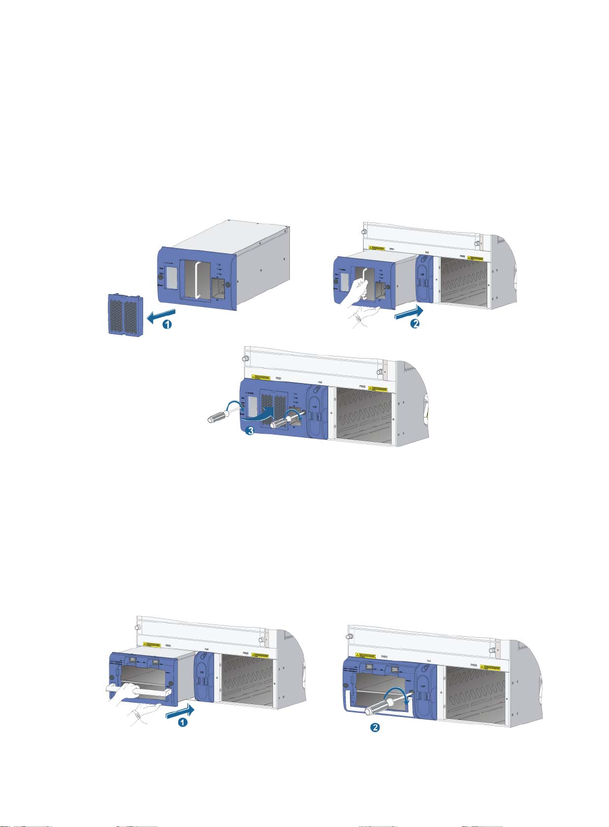
Replacing a power supply system ································································································································ 48
Replacing a DC power supply ····························································································································· 48
Replacing an AC power supply ··························································································································· 49
Cleaning a power supply air filter ······························································································································· 51
Replacing a card ···························································································································································· 51
Replacing a subcard ······················································································································································ 53
Replacing a fan tray ······················································································································································ 54
Replacing a fan tray for an A8805/A8812 ······································································································ 54
Replacing a fan tray for an A8808 ···················································································································· 55
Replacing a chassis air filter ········································································································································· 56
Replacing chassis air filters for an A8808 ········································································································· 56
Replacing an air filter for an A8805/A8812 ··································································································· 57
Replacing a CF card ······················································································································································ 57
Replacing a transceiver module ··································································································································· 59
Hardware specifications ············································································································································ 61
Environmental requirements ·········································································································································· 61
Technical specifications ················································································································································· 61
Chassis ··································································································································································· 61
Cooling system ······················································································································································ 68
Card specifications ··············································································································································· 71
Power supply system ············································································································································· 77
LEDs ············································································································································································· 84
Power supply LEDs ························································································································································· 84
Fan LEDs ·········································································································································································· 84
MPU LEDs ········································································································································································ 85
CF card status LED ················································································································································· 85
Network management port LEDs ························································································································· 85
LPU status LEDs ······················································································································································· 86
MPU status LEDs ···················································································································································· 86
SPC card LEDs ································································································································································ 86
LINK/ACT LED ······················································································································································· 87
Combo interface LED ············································································································································ 87
LINK and ACT LEDs ··············································································································································· 87
SPE card LED ·································································································································································· 88
Subcard LEDs ·································································································································································· 88
iv
Page 5

Transceiver modules ··················································································································································· 89
10-GE XFP transceiver modules ···································································································································· 89
FE/GE SFP transceiver modules ··································································································································· 90
OC-48/STM-16 SFP transceiver modules ··················································································································· 92
OC-12/STM-4 SFP transceiver modules ······················································································································ 92
OC-3/STM-1 SFP transceiver modules ························································································································ 92
Lightning protection ···················································································································································· 94
Connecting the AC power supply to a power strip with lightning protection ························································· 94
Installing a lightning protector for a network port ······································································································ 95
Engineering labels ····················································································································································· 96
Labels for cables····························································································································································· 96
Labels for signal cables ········································································································································ 96
Labels for power cables ········································································································································ 96
Generic labels························································································································································ 97
Labels for devices ··························································································································································· 98
Filling in labels ······························································································································································· 98
Affixing labels ································································································································································· 98
Affixing a label to a signal cable ························································································································ 98
Affixing a label to a power cable ······················································································································· 99
Affixing a generic label ······································································································································ 100
Affixing a label to a device ································································································································ 101
Guidelines ····································································································································································· 101
Examples ······································································································································································· 101
Engineering labels for network cables ·············································································································· 101
Engineering labels for optical fibers·················································································································· 103
Engineering labels for DC power cables ·········································································································· 105
Engineering labels for AC power cables ·········································································································· 106
Engineering labels for devices ··························································································································· 106
Cable management ················································································································································ 108
Cable management guidelines ··································································································································· 108
Cable management examples ···································································································································· 109
Support and other resources ·································································································································· 112
Contacting HP ······························································································································································ 112
Subscription service ············································································································································ 112
Related information ······················································································································································ 112
Documents ···························································································································································· 112
Websites ······························································································································································· 112
Conventions ·································································································································································· 113
v
Page 6

p
W
Preparing for installation
Overview
This series is a line of data center routers. You can deploy the A8800 routers at the core layer and
distribution layer of large-scale MANs, the core layer of enterprise networks, and the distribution layer
of carrier networks. Table 1 lists the chassis models in the series.
Table 1 Router chassis
Chassis Power in
A8805 AC/DC Horizontal 2 5
A8808 AC/DC Vertical 2 8
A8812 AC/DC Horizontal 2 12
NOTE:
•
An MPU is the supervisor engine of a router. An LPU receives and forwards traffic and provides network
services.
• The LPU slots can hold SPE cards, SPC cards, and OAA modules. For card specifications, see
"Hardware specifications."
ut Card slot orientation MPU slots LPU slots
Safety recommendations
ARNING!
Before installation and operation, read all of the safety instructions in the
supplied with your device.
This section provides general recommendations. For more information, see the Compliance and
Safety Guide.
Compliance and Safety Gui
de
• Turn off all power and remove all power cables before opening the chassis.
• Unplug all power and external cables before moving the chassis.
• Locate the emergency power-off switch before installation and shut off power immediately if
necessary.
• Always wear an ESD-preventive wrist strap when installing the router.
• Do not stare into the open optical interface. The laser light emitted from the optical fiber may
hurt your eyes
• Use a good grounding system to protect your router against lightning shocks, interference, and
ESD. This is essential to the operating reliability of your router.
• Make sure the resistance between the chassis and the ground is less than 1 ohm.
1
Page 7

Installation site requirements
p
y
y
x
The following tables provide information about temperature and humidity, cleanness, and air quality
requirements.
CAUTION:
If condensation appears on the router when you move it to a high-temperature environment, dry the
router before powering it on to avoid short circuits.
To ensure normal operation of the router, make sure the room temperature meets the requirements
described in Table 2.
Table 2 Temperature requirements
Tem
erature Range
Long term: 0°C to 45°C (32°F to 113°F)
Operating temperature
Storage temperature –40°C to +70°C (–40°F to +158°F)
Maintain appropriate humidity in your equipment room, as described in Table 3.
Table 3 Humidity requirements
Short term: –10°C to +55°C (14°F to 131°F) (no more than 96 hours of
continuous operation in less than 15 days in one year)
Humidit
Operating humidity (noncondensing) 5% to 95%
Storage humidity (noncondensing) 5% to 95%
Range
Lasting high relative humidity tends to cause poor insulation, increased electricity consumption,
mechanical property change of materials, and corrosion of metal parts. Lasting low relative humidity
is likely to result in loose screws due to washer contraction, and even ESD, which causes the circuits to
fail.
Table 4 Dust concentration limit in the equipment room
Ph
sical active substance Concentration limit (particles/m3)
Dust particle ≤3 x 10⁴ (No visible dust on desk over three days)
Note: Dust particle diameter ≥ 5μm
Table 5 Limits on harmful gases in the equipment room
Gas Ma
SO
2
H2S 0.06
concentration (mg/m3)
0.2
NH
3
Cl
2
0.05
0.01
2
Page 8

Rack-mounting requirements
Before rack-mounting a router, make sure the rack meets the following requirements:
• HP recommends that the router is mounted in an open rack. If you mount a router in a closed
rack, make sure there is a good heat dissipation system.
• The rack is steady enough to support the router and accessories.
• The router fits the rack size. Leave some space beside the left and right panels of the router for
chassis heat dissipation.
Installation tools
Accessories supplied by the router
Item Quantity Purpose
Console cable 1
Grounding cable 1 Grounding the router
Mounting brackets 1 pair Fastening the router to the rack
Cable management
brackets
M4*8 screw 1 set
M6*12 screw 1 set
M6 cage nut 1 set
ST2.9*9.5 selftapping screw
Impedance carrier
ESD-preventive wrist
strap
1 pair Cable management
1 set
1 (supplied with the
A8808 only)
1 ESD prevention
Connecting the console port and the configuration
terminal for router login
• Fastening the mounting brackets to the router
• Fastening the cable management brackets to the
Fastening the router to the rack
Fastening the cable management brackets to the
mounting brackets (excluding the A8808)
Installed at the rear of the router to block air from
entering the chassis
router
NOTE:
The number of screws and nuts supplied with the router may vary.
User-supplied tools and equipment
• Cross-head screwdriver P1 – 100 mm, P2 – 150 mm, and P3 – 250 mm
• Flat-blade screwdriver P4 – 75 mm
• Diagonal pliers, wire-stripping pliers, and wire clippers
• Meters and equipment such as hub and multimeter
3
Page 9

The rack accessories and installation tools are not described in this section. The accessories and
installation tools may vary depending on the rack model. For more information, see the installation
guide for the corresponding rack.
4
Page 10
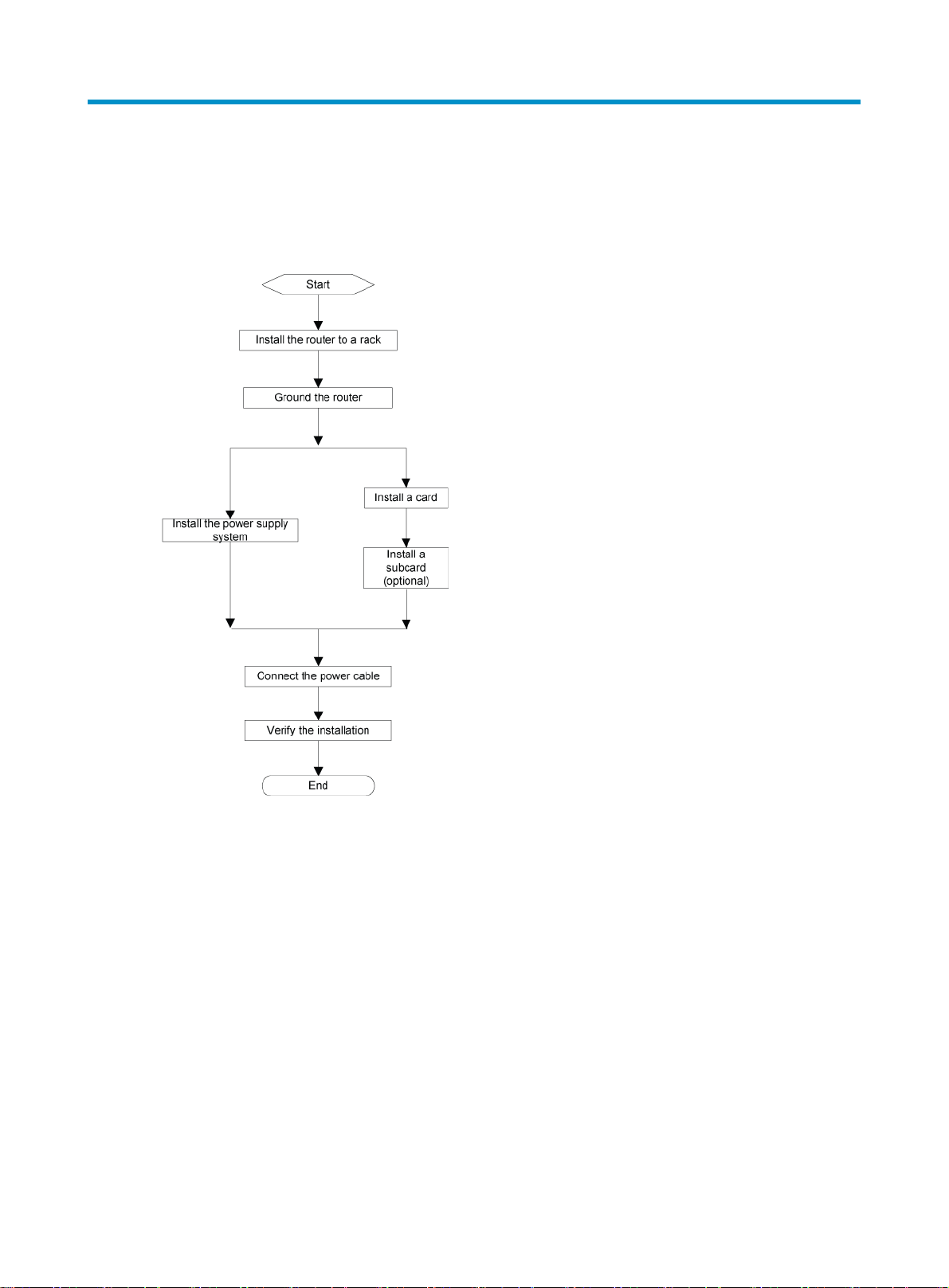
Installing the router
Figure 1 shows the steps for installing the router.
Figure 1 Installation flowchart
Installation prerequisites
Before installing the router:
• Read "Preparing for installation" carefully and make sure the installation site meets all of the
requirements.
• Using the packing list supplied with your router, inspect the router to make sure you have all of
the items listed and verify that the router was not damaged during shipment. If anything is
damaged or missing, contact HP immediately.
Installing the router in a rack
Confirm the following before starting installation:
• The rack is sturdy and securely grounded.
• There is at least 0.8 m (2.62 ft) of clearance around the rack for heat dissipation and installation.
5
Page 11
• There is no debris inside or around the rack.
• The router can be installed only in a 4-post 19-inch standard rack.
Mounting slide rails to the rack
If the rack already has slide rails, skip this section. Slide rails or rack shelves are not provided with the
router. Prepare them yourself or order them from HP. Make sure the slide rails or rack shelves you use
are standard accessories.
In addition to slide rails, you can use a rack shelf to support the router. This document describes how
to install slide rails only.
The following procedure uses a 19-inch rack as an example.
Before installing the slide rails, verify that the slide rails can support the weight of the router. For the
weights of the router, see "Hardware specifications."
To install the slide rails:
1. Mark the positions of the slide rails on the rack. Make sure the space above the slide rails is
greater than the height of the router chassis. For the router dimensions, see "Hardware
specifications."
2. Install the slide rails to the lowest possible position when installing a single router on the rack.
Make sure the bottom edge of the slide rail aligns with the middle of the narrower metal area
between holes.
3. Align the screw holes on the two sides of the slide rails with the corresponding holes on the
rack, and then fasten the screws.
4. Install the other slide rail in the same way. Keep the two slide rails at the same height so that
the router can be placed evenly.
The height of the front panel of the rack is a measurement of one RU (44.45 mm, or 1.75 in). As
shown in Figure 2, each 1 RU has three holes with center-to-center spacing between the holes of
15.87 mm (0.63 in), 15.87 mm (0.63 in), and 12.70 mm (0.5 in).
Figure 2 Installing the slide rails
(1) Middle of the narrower metal area between holes (2) 1 RU
6
Page 12
NOTE:
The appearance and installation methods of slide rails depend on the slide rail types.
Installing cage nuts to the rack
Before mounting the chassis to the rack, install cage nuts to the front square-holed brackets of the rack,
as shown in Figure 3.
When preparing for installation, make sure the total height of the routers to be installed does not
exceed the height of the rack, and reserve enough clearance for cable routing.
1. Align the mounting bracket with the left rack post, making sure the bottom edge and the slide
rail are level.
2. Mark the positions of the cage nuts on the rack post according to the installation holes on the
mounting bracket.
3. Install the cage nuts to the right positions. (Each installation hole on the mounting bracket
corresponds to one cage nut.)
4. Repeat steps 1 through 3 to install cage nuts to the correct rack post.
Figure 3 Installing the cage nuts
Installing the cable management brackets
This section includes separate steps for installing the cable management brackets on the A8808 and
A8805/A8812.
Installing the cable management brackets on the A8808
The A8808 has two cable management brackets and are installed using the same procedure. The
signal cable management brackets are installed at the upper part of the router, and the power cable
management brackets are installed at the lower part of the router.
7
Page 13
To install a cable management bracket:
1. Attach the cable management bracket to the chassis, and align the screw holes on the cable
management bracket with the screw holes on the chassis, as shown in Figure 4.
2. Screw in and fasten the M4 screws with a screwdriver.
Figure 4 Installing the cable management brackets on the A8808
Installing the cable management brackets on the A8805/A8812
Install the cable management brackets to the mounting brackets (cable management brackets and
mounting brackets are required at both sides of the chassis). Figure 5 shows how to install a right
cable management bracket. The method for installing the left cable management bracket is the same
as the right.
8
Page 14
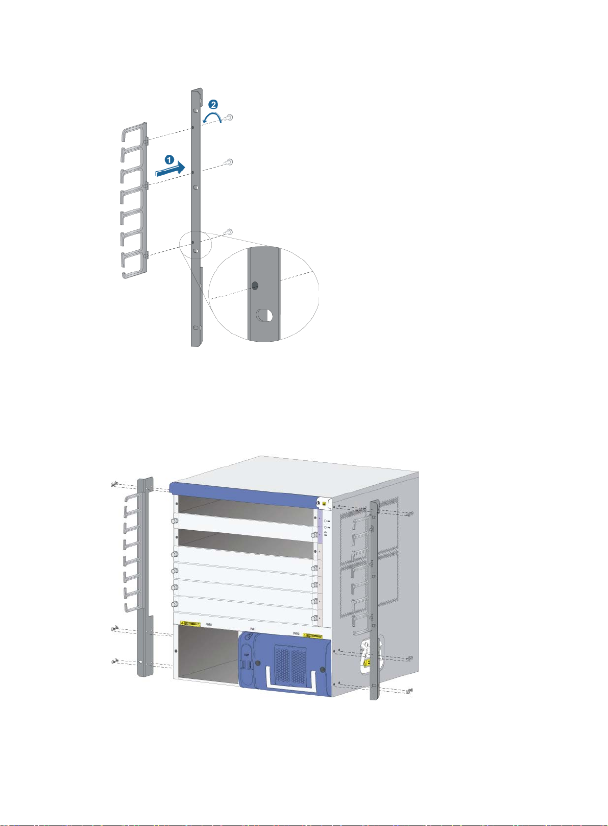
Figure 5 Installing the cable management bracket on the A8805/A8812
Installing the mounting brackets
Before installing the router to the rack, install the mounting brackets to the chassis. Figure 6 shows
how to install the mounting brackets to an A8805 router.
Figure 6 Installing the mounting brackets
9
Page 15
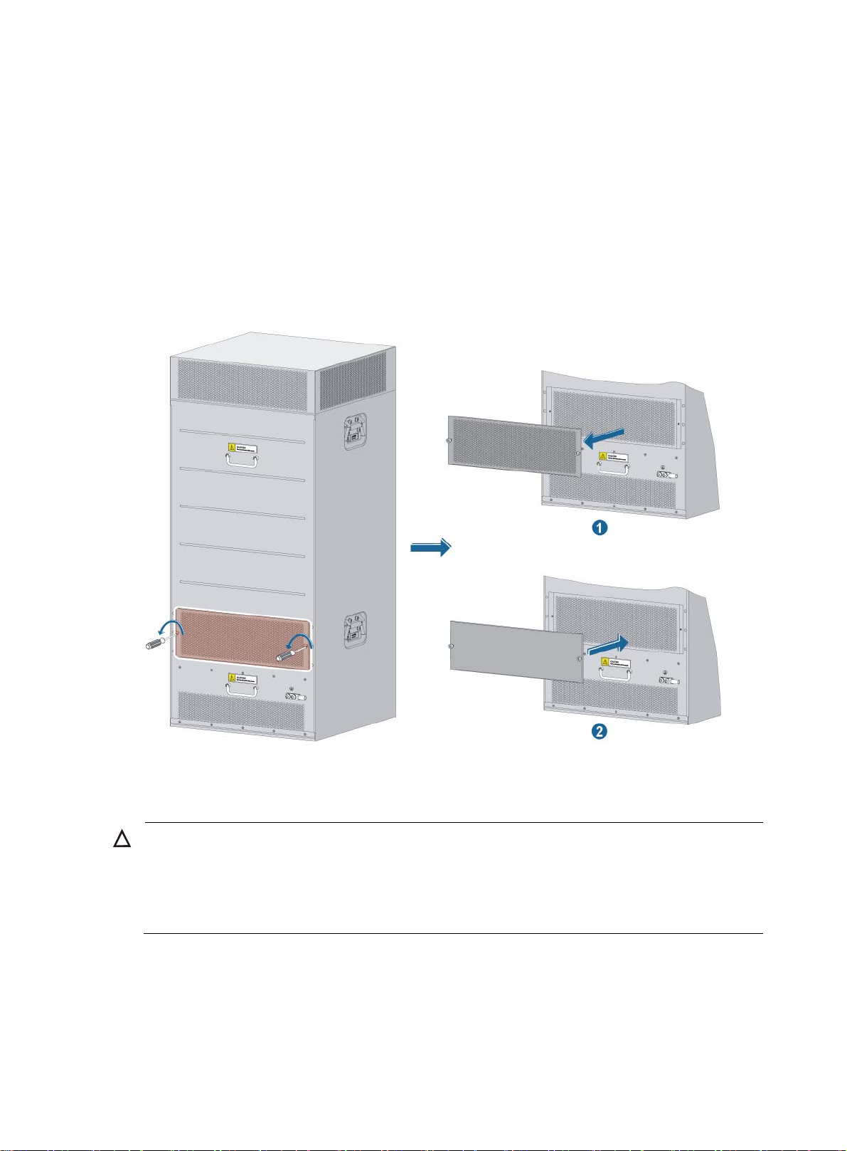
Installing an impedance carrier (optional)
An impedance carrier is shipped with the A8808 only. You can install the impedance carrier at the
rear of the chassis (where an air filter is located) to block the airflow from entering the rear of the
chassis.
Install an impedance carrier for routers that have front-to-rear airflow, as shown in Figure 7.
To install an impedance carrier:
1. Loosen the captive screws on the air filter to remove the air filter.
2. Install the impedance carrier, and fasten the captive screws on the impedance carrier.
Figure 7 Installing an impedance carrier
Installing the router to a rack
CAUTION:
• Make sure you have installed a rack shelf or slide rails on the rack for supporting the router, and the
rack shelf or the slide rails are sturdy enough to support the weight of the router chassis and all
accessories. Do not install the router to the rack using only mounting brackets.
• To install multiple routers on the rack, mount the heaviest router at the bottom of the rack.
To mount the router in the rack:
1. Use several people to place the router on the rack shelf or slide rails, and then slide the router
into the rack until the mounting brackets on the router touch the front rack posts.
2. Fasten the mounting brackets to the rack posts with mounting screws, as shown in Figure 8. If
the screw holes on the mounting brackets cannot align with the cage nuts on the rack, verify
10
Page 16
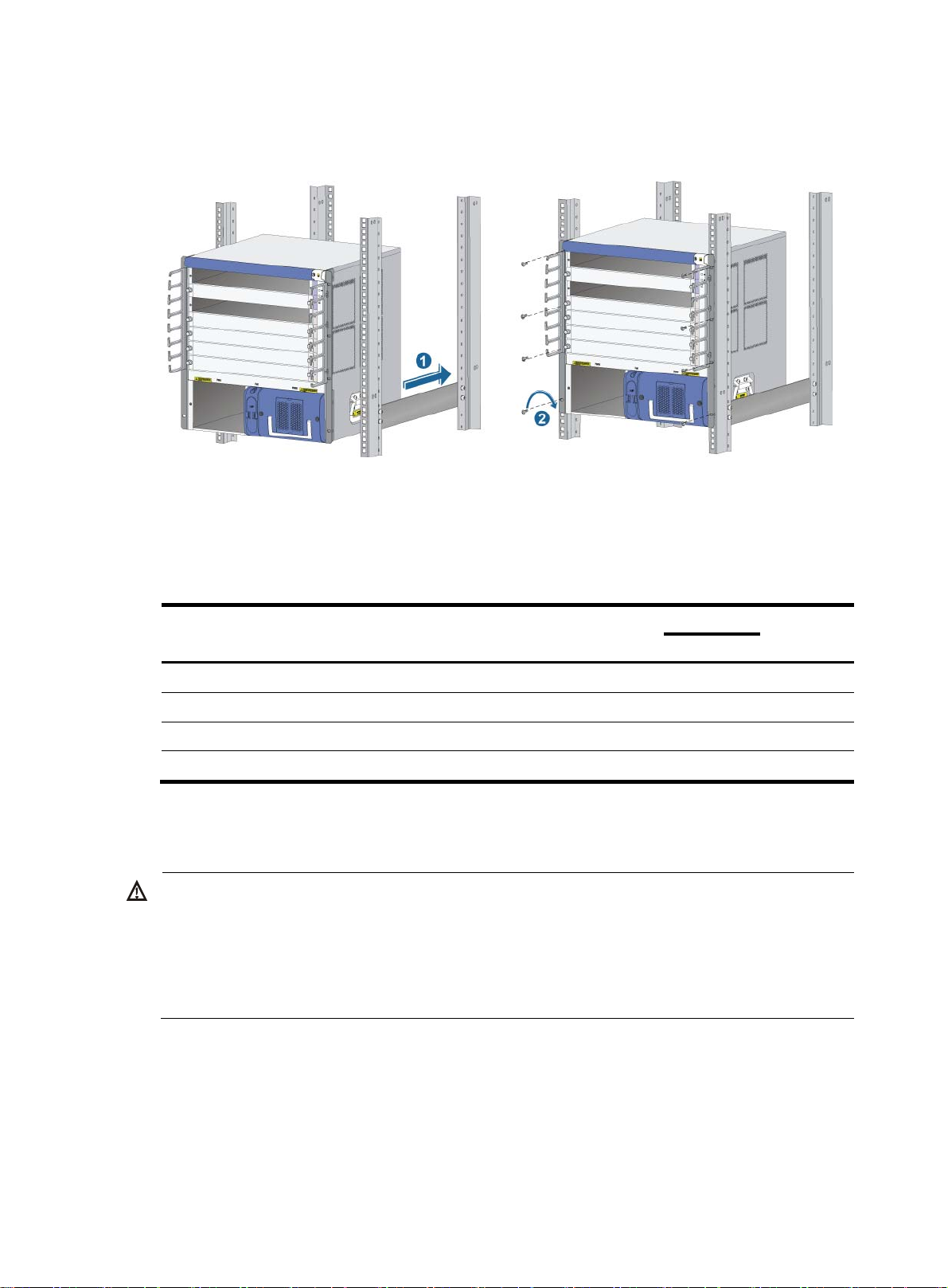
that the bottom edge of the slide rail aligns with the middle of the narrowest metal area
W
g
between holes, and that the cage nuts are installed in the correct holes.
Figure 8 Installing the router in a standard 19-inch rack
Verifying the installation
Use the following checklist to make sure the router has been installed correctly.
Table 6 Installation checklist
Item
Mounting brackets are firmly attached to the router.
The router is installed in the correct position.
Mounting brackets on the router are firmly attached to the rack.
There is enough space for heat dissipation around the router.
Grounding the router
ARNING!
For the safety of operators and equipment, ground the router securely. Make sure the resistance
reading between the router chassis and the ground is less than 1 ohm. Most racks are equipped with a
grounding strip. You can connect the yellow-green grounding cable of the router to the
Connect the grounding cable to the earthing system in the equipment room. Do not connect it to a fire
main or lightning rod.
Result
Remarks
Yes No
rounding strip.
The positions of the grounding terminals on the A8805, A8808, and A8812 are similar. The
following procedure uses the A8805 as an example.
To connect the grounding cable:
1. Remove the grounding screw from the router chassis, as shown in Figure 9.
2. Put the supplied OT terminal of the grounding cable on the grounding screw. Use the supplied
grounding cable (CAT 6 cable with dual-hole OT terminals).
11
Page 17
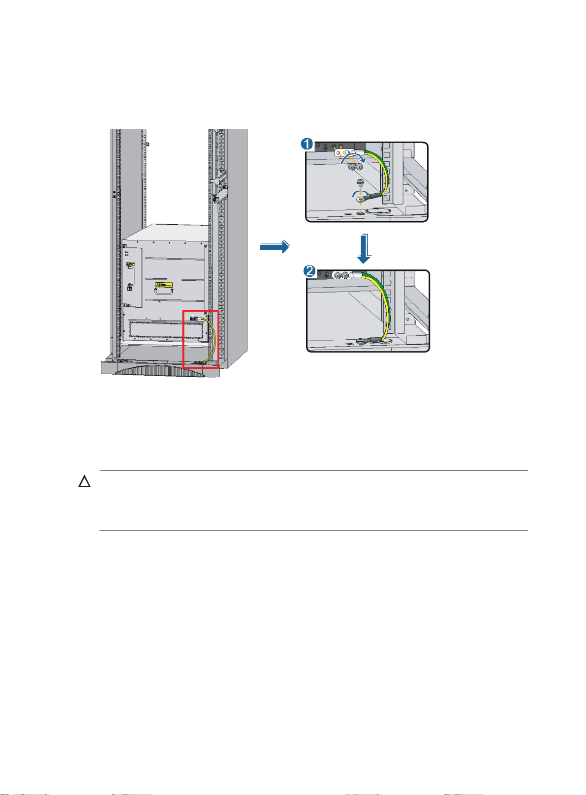
3. Insert the grounding screw into the grounding hole and tighten the screw.
g
4. Connect the other end of the grounding cable to the grounding strip of the rack in the same
way.
Figure 9 Connecting the grounding cable
If there is no grounding point on the rack, you can attach the grounding cable to a grounding strip.
The installation procedures are similar.
Installing the power system
CAUTION:
Hold a power supply by the bottom when moving it. Never attempt to lift a power supply by its handle
because the handle is not desi
to the power supply.
The router supports both AC and DC power supply modes. You can select either AC or DC power
supply mode as needed. 1+1 redundancy is recommended.
• DC power supply—Includes NEPS2000-D and NEPS3500-D models.
• AC power supply—One or two AC power supplies are installed in the AC power frame
NEPS3500-A.
To prepare for installation:
1. Put on an ESD-preventive wrist strap and make sure it is properly grounded.
ned to support weight. Doing so might result in bodily injury or damage
2. Make sure the power switch of the power supply is in the OFF position.
3. Remove the blank panel (if any) from the slot to be used.
12
Page 18
Installing a DC power supply
1. Remove the air filter frame of the power supply and gently pull the DC power supply handle out.
2. Holding the handle of the power supply with one hand and supporting the bottom of the power
supply with the other hand, push the power supply slowly along the slide rails until it makes
close contact with the backplane, as shown in Figure 10.
3. Fasten the mounting screws on the power supply panel with a Phillips screwdriver.
4. Cover the power supply with the removed air filter frame.
Figure 10 Installing a DC power supply
Installing an AC power supply
Installing a NEPS3500-A AC power frame
For a router that requires power supply redundancy, install the same number of power supplies in the
two power frames.
1. Push the power frame slowly along the slide rails until it makes close contact with the backplane.
2. Fasten the mounting screws on the power frame panel with a Phillips screwdriver.
Figure 11 Installing a NEPS3500-A power frame
13
Page 19
Installing an NEPS1800-A AC power supply
1. Pull the handle of the power supply downward to the unlock position.
2. Gently push the power supply into the AC power frame (NEPS3500-A) until the rear side of the
power supply makes close contact with the power frame backplane.
3. Push the handle upward so that it locks the power supply in place.
Figure 12 Installing an AC power supply
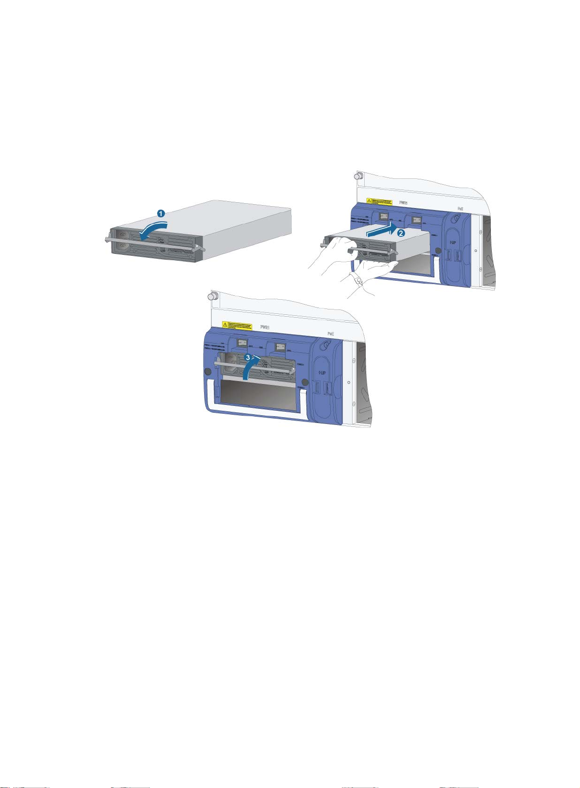
Installing a card
All cards (excluding subcards) for the routers are hot-swappable.
You install MPUs and LPUs in the same way.
To prepare for installation:
1. Put on an ESD-preventive wrist strap and make sure it is properly grounded.
2. Remove the blank panel (if any) from the slot to be used. Keep the blank panel and protection
cover for future use
3. Prepare the card to be installed.
To install a card:
1. Remove the protection cover before installing the card:
a. Put on an ESD-preventive wrist strap, and then use a Phillips screwdriver to loosen the
captive screws that fasten the card to the protection cover.
b. Gently pull the card out of the protection cover, as shown in Figure 13.
14
Page 20
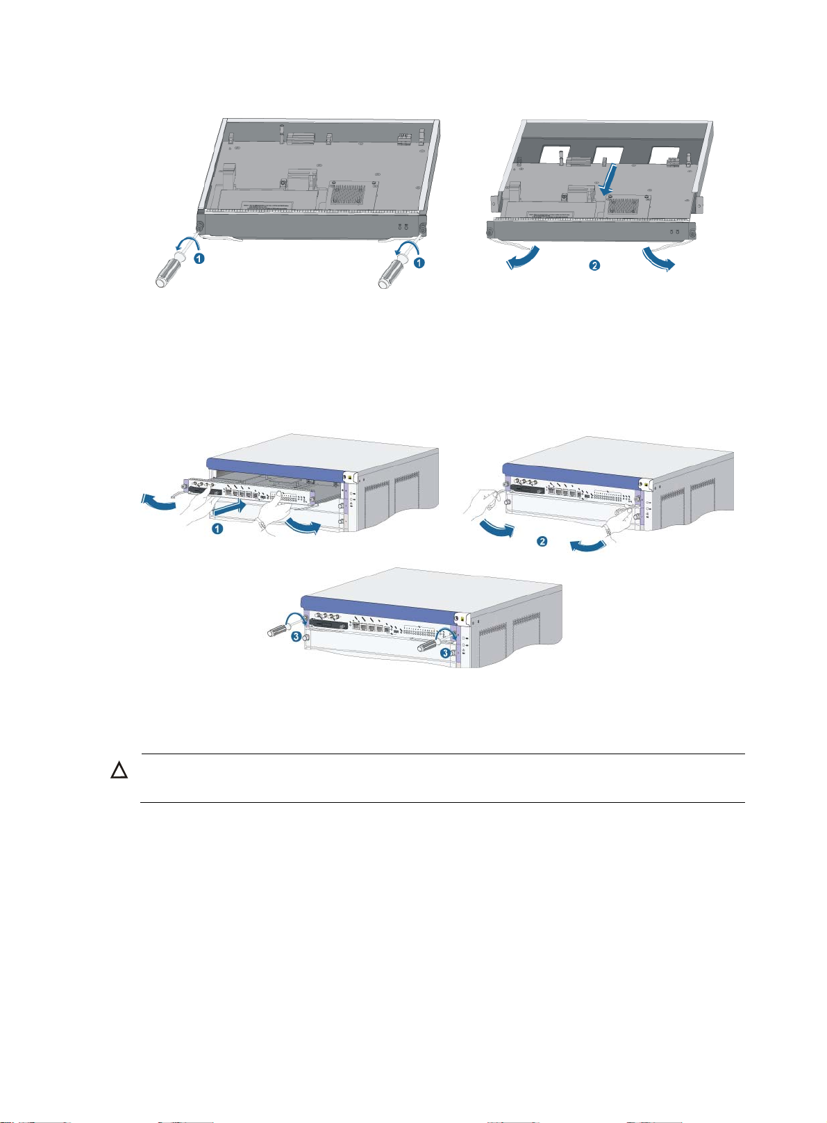
Figure 13 Removing the protection cover
2. Move the ejector levers of the card outward. Supporting the bottom of the card with both hands,
slowly push the card into the slot along the slide rails.
3. Push the ejector levers inward to ensure close contact between the card and the backplane.
4. Position the screws in the holes and fasten them with a screwdriver to attach the card.
Figure 14 Installing a card
Installing an SPE subcard
CAUTION:
Do not install a subcard to the SPE card when the router is powered on.
This section describes how to install a subcard to an SPE card. The installation of an SPE card is the
same as a common card. For more information, see "Installing a card"
The subcards are not hot-swappable. You can install a subcard using one of the following methods:
• Power off the router and install the subcard to the SPE card on the router.
• When the router is powered on, install the subcard to the SPE card that has not been installed,
and then install them to the router.
To prepare for installation:
1. Put on an ESD-preventive wrist strap and make sure it is properly grounded.
2. Make sure the router is powered off and installed with the SPE card.
15
Page 21
3. Remove the blank panel (if any) from the slot to be used on the SPE card.
4. Unpack the subcard.
To install a subcard:
1. Turn the ejector levers of the subcard outward simultaneously with both hands, and then slide
the subcard (with the right side up) straight into the SPE card along the slide rails until the
ejector levers touch the panel of the SPE card, as shown in Figure 15.
2. Push against the front panel of the subcard. When the front panel is close enough to the SPE
card, pivot the ejector levers of the subcard inward with both hands so that the front panel is
flush with the panel of the SPE card.
3. Use a Phillips screwdriver to fasten the mounting screws on the subcard.
Figure 15 Installing a subcard
Connecting power cables
Check the following items before connecting power cables:
• For lightning protection, the AC power should be routed through an external lightning device
into the router. For more information, see "Lightning protection."
• The power switch on the power supply is in the OFF position.
16
Page 22
Connecting an AC power cable
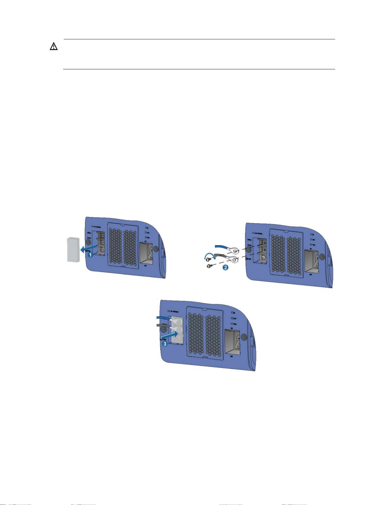
A
CAUTION:
NEPS3500-A requires a 16 A power cable (AC), so you must use a 16 A busbar and make sure the
C power source can provide enough power.
The following procedure uses the AC power supply that comprises one 3500 W AC power frame and
two 1800 W power supplies to show how to install AC power cables.
To connecting an AC power cable:
1. Insert the ends of the bail latch into the holes on the left side of the upper power supply.
2. Connect one end of the AC power cable to the AC receptacle on the module.
3. Use a wiring tie through a notch of the bail latch, and bend the power cable so that the wiring
tie can bind the power cable with the bail latch.
4. Repeat steps 2 and 3 to bind another power cable with a wiring tie through the other notch.
5. Connect the other end of the AC power cable to the external power supply system.
Figure 16 Connecting a NEPS3500-A AC power cable
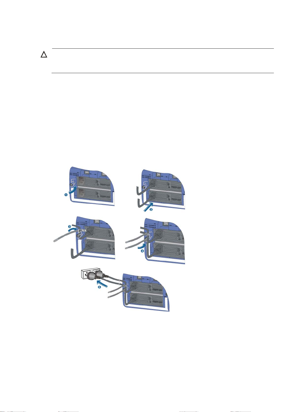
Connecting DC power cables
The DC power cables for the NEPS2000-D and NEPS3500-D are connected in the same way. The
procedure in this section uses the NEPS2000-D.
17
Page 23
W
ARNING!
To protect operators from being shocked, install the protection cover over the DC terminal block
immediately after you connect the power cables.
To connect the DC power cables:
1. Remove the protection cover of the DC terminal block from the DC power supply.
2. Loosen the fastening screws on the top two terminals with a Phillips screwdriver.
3. Connect one end of the blue –48 VDC power cable to the negative terminal (–) on the power
supply and fasten the screw. Connect the other end of the cable to the negative –48 V terminal
(–) on the power source.
The –48 VDC cable is marked with a minus sign (–).
4. Connect one end of the black DC power cable to the RTN (+) terminal on the power supply and
fasten the screw. Connect the other end of the cable to the RTN (+) terminal on the power
source.
The black DC power cable is marked with a plus (+) sign.
5. Put the protection cover over the DC terminal block.
Figure 17 Connecting DC power cables
18
Page 24

W
Verifying the installation
ARNING!
Before verifying the installation, make sure you have turned off the power to avoid bodily injury and
router damage.
Use the following checklist to make sure the router has been installed correctly.
Table 7 Installation checklist
Item
The grounding cable is grounded correctly.
Power supplies are installed correctly and firmly seated.
Power cables are connected correctly.
MPUs are installed correctly and have close contact with the
backplane.
LPUs and subcards are installed correctly and have close contact
with the backplane.
Result Remarks
Yes No
19
Page 25
Connecting the router to the network
Logging in to the router
The most common way to log in to a router is through the console port. It is also the prerequisite to
configuring other login methods.
Connecting the console cable
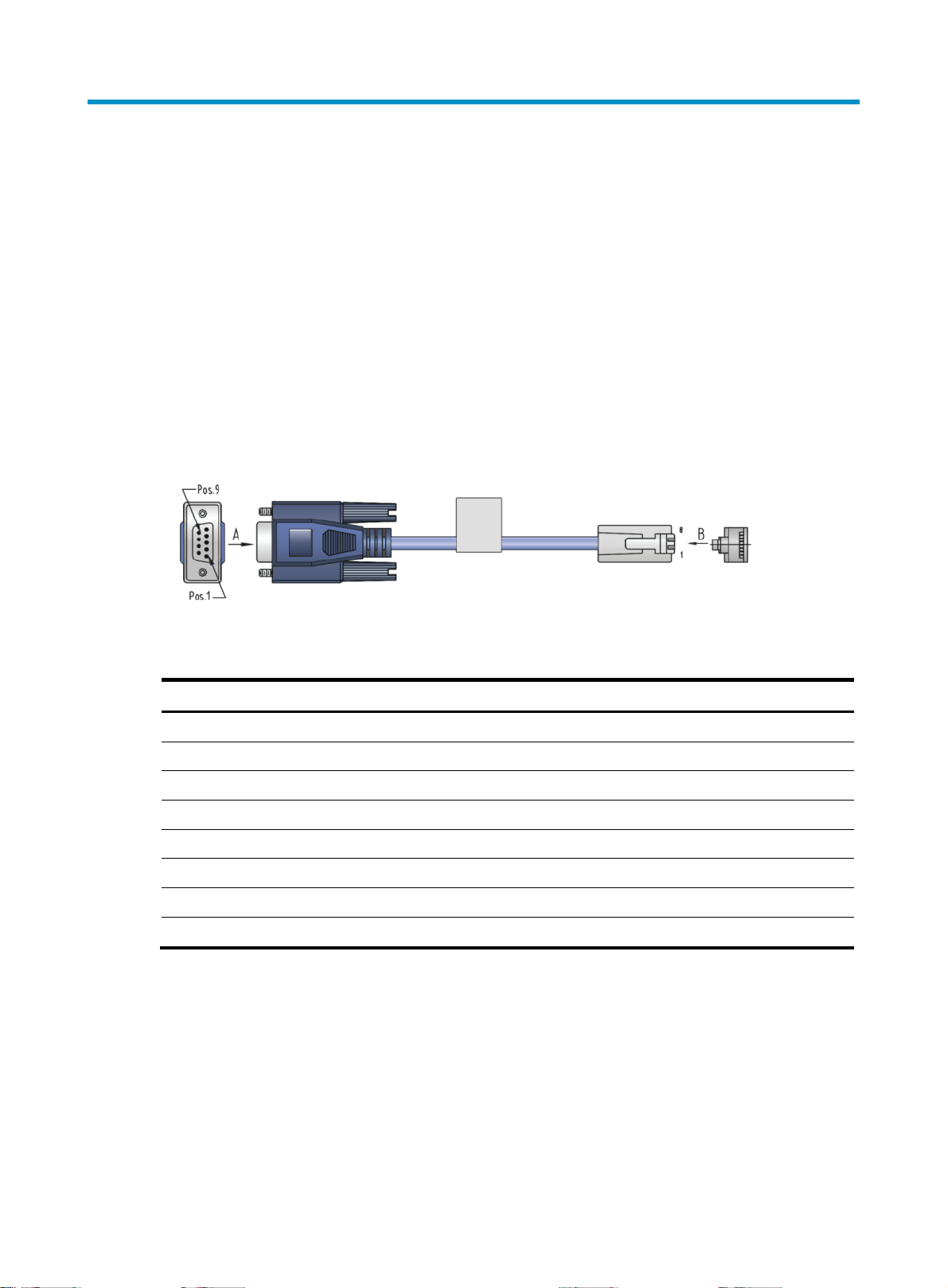
A console cable is an 8-core shielded cable, with a crimped RJ-45 connector at one end for
connecting to the console port of the router, and a DB-9 female connector at the other end for
connecting to the serial port on the console terminal, as shown in Figure 18.
Figure 18 Console cable
Table 8 Console cable pinouts
RJ-45 pin Signal DB-9 pin Signal
1 RTS 8 CTS
2 DTR 6 DSR
3 TXD 2 RXD
4 CD 5 SG
5 GND 5 SG
6 RXD 3 TXD
7 DSR 4 DTR
8 CTS 7 RTS
20
Page 26
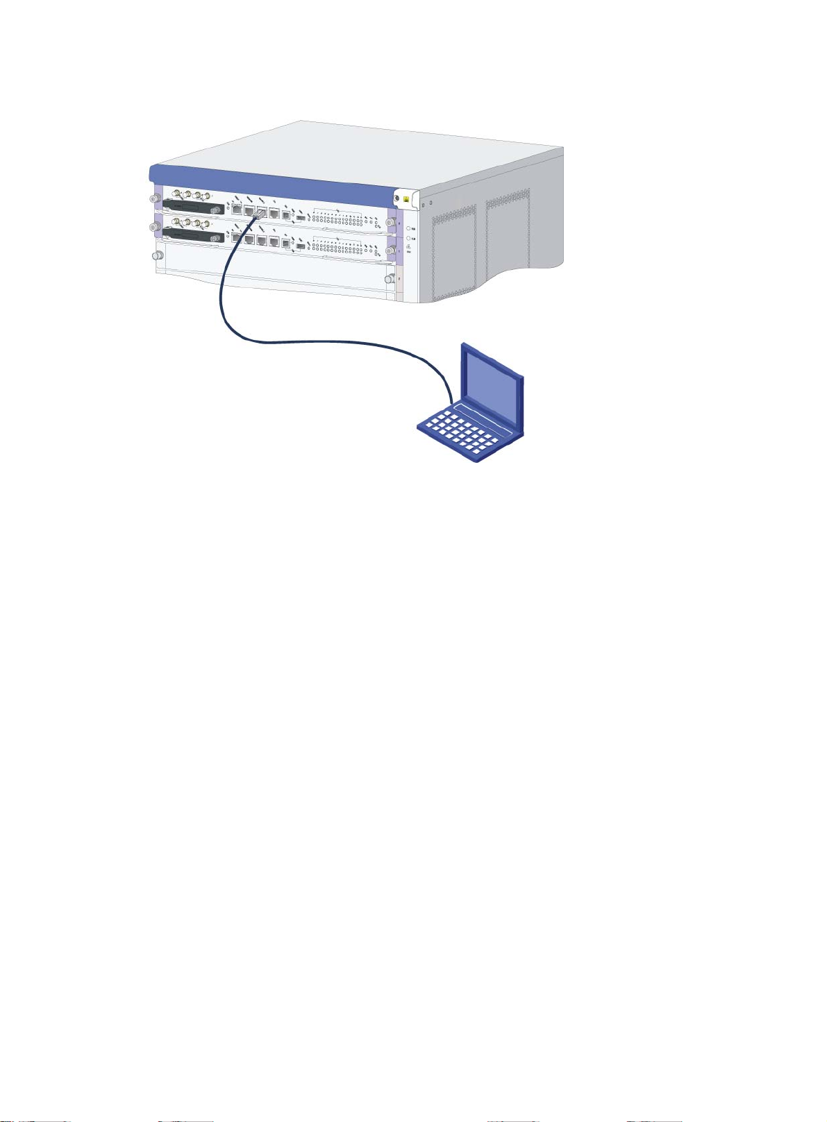
Figure 19 Connecting the router and the PC through the console port
To connect the console cable:
1. Connect the DB-9 connector of the console cable to the serial port of a PC or terminal.
2. Connect the RJ-45 connector of the console cable to the console port of the MPU of the router.
3. When you remove the console cable, first unplug the RJ-45 end, and then unplug the DB-9 end.
Setting up a configuration environment
1. Launch a terminal emulation utility (such as HyperTerminal in Windows XP/Windows 2000).
Select Start > All Programs > Accessories > Communications > HyperTerminal to access the
HyperTerminal window.
The Connection Description dialog box appears.
21
Page 27
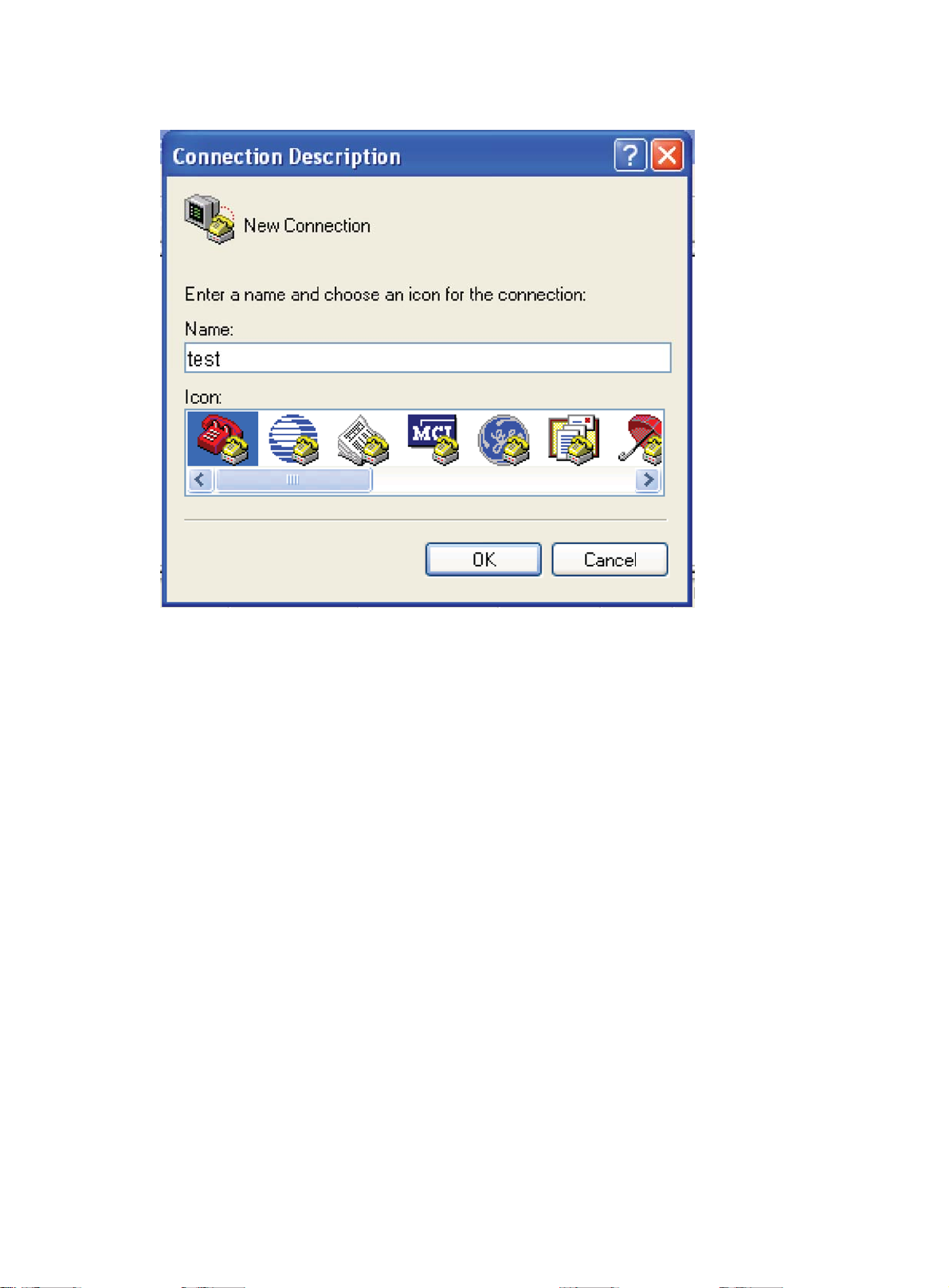
Figure 20 Connection Description dialog box for HyperTerminal
2. Enter the name of the new connection in the Name box, and then click OK.
The system displays the interface, as shown in Figure 21.
22
Page 28
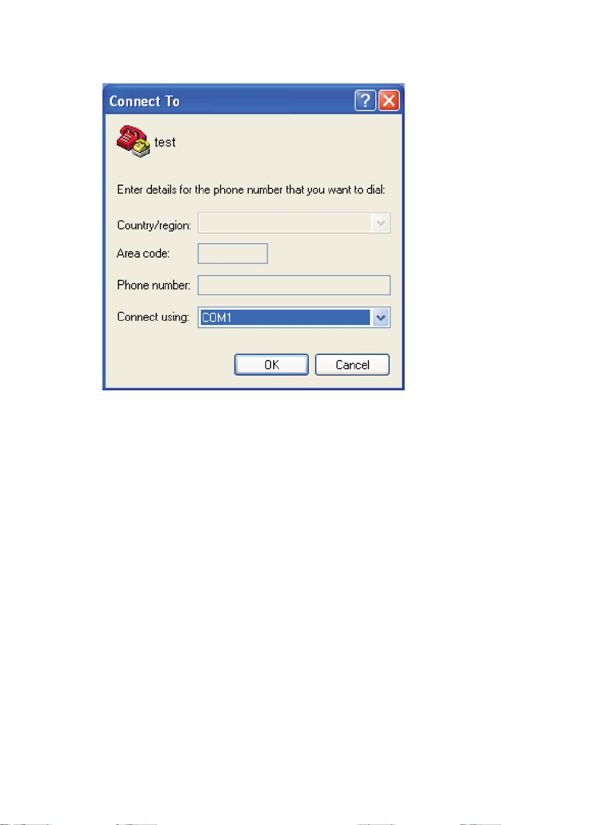
Figure 21 Selecting a port for the HyperTerminal connection
3. Select a port from the Connect using list, and then click OK.
4. Set the Bits per second to 9600, Data bits to 8, Parity to None, Stop bits to 1, and Flow control
to None, and click OK.
23
Page 29
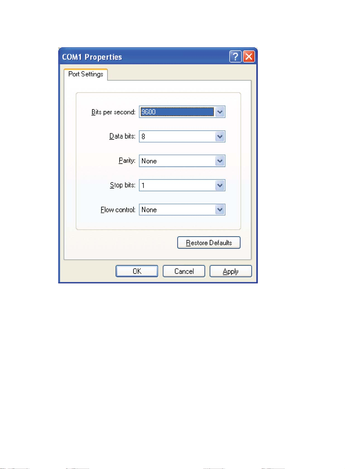
Figure 22 Setting the serial port parameters
24
Page 30
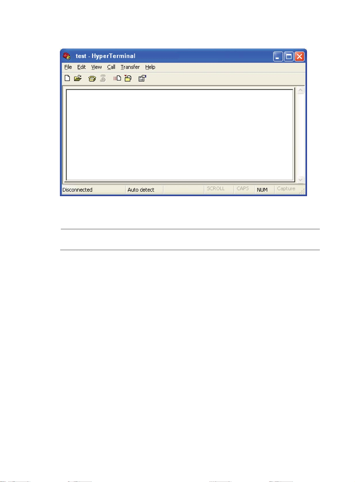
Figure 23 HyperTerminal window
5. Select File > Properties in the HyperTerminal window.
6. On the Settings tab, select VT100 for terminal emulation, and click OK.
NOTE:
HP recommends that you select the Windows keys option.
25
Page 31

Figure 24 Setting the terminal emulation parameters
Powering on the router
CAUTION:
Before powering on the router, locate the power switch in the equipment room so that you can
disconnect the power supply promptly in case of an emergency.
Before powering on the router, confirm the following:
• The interface cables, power cables, and grounding cable are connected correctly.
• The power outlet voltage is the same as indicated on the router label.
• The console cable is correctly connected, the console terminal or PC is powered on, and the
terminal parameters are configured properly.
To power on the router:
1. Turn on the power switch of the power source providing power to the router.
26
Page 32

2. Turn on the power switch on the router.
Before the router is powered on, the following information is displayed:
DDR2 SDRAM test successful.
System is starting...
Booting Normal Extend BootWare
The Extend BootWare is self-decompressing..........................
Done!
****************************************************************************
* *
* HP A8800 BootWare, Version 1.10 *
* *
****************************************************************************
Copyright (c) 2010-2011 Hewlett-Packard Development Company, L.P.
Compiled Date : Apr 22 2011
CPU Type : MPC8548E
CPU L1 Cache : 32KB
CPU L2 Cache : 512KB
CPU Clock Speed : 1000MHz
Memory Type : DDR2 SDRAM
Memory Size : 1024MB
Memory Speed : 400MHz
BootWare Size : 4MB
Flash Size : 128MB
cfa0 Size : 247MB
NVRAM Size : 1024KB
BASIC CPLD Version : 001F
EXTEND CPLD Version : 001F
PCB Version : Ver.B
The router initiates the POST and the results are displayed at the console terminal.
Board self testing...........................
Board steady testing... [ PASS ]
Board SlotNo... [ 0 ]
Subcard exist testing... [ PASS ]
DX246 testing... [ PASS ]
PHY88E1111 testing... [ PASS ]
CPLD1 testing... [ PASS ]
CPLD2 testing... [ PASS ]
NS16550 register testing... [ PASS ]
The device's Mac address... [00:23:89:D4:00:00]
CF Card testing... [ PASS ]
BootWare Validating...
Press Ctrl+B to enter extended boot menu...
When the POST is complete, the router boots the applications. The following information appears on
the terminal screen (only a portion is shown in this example):
Starting to get the main application file--cfa0:/A8800.BIN!..
The main application file is self-decompressing.............................
System application is starting...
27
Page 33

kbd->bi_immr_base = 0xff700000.
Starting kernel at 0x10000 ...
Now beginning to initialize system
User interface con0 is available.
After the router completes booting the applications, the following information appears on the terminal
screen:
Press ENTER to get started.
3. Press Enter to begin configuring the router at the prompt:
<HP>
NOTE:
• The router displays a CLI. For more information about the CLI, see
Configuration Guide
.
• The output depends on your router model.
Verifying router operation (recommended)
HP recommends that you verify the following after the router is powered on:
• The cooling system is working. You should be able to hear fan rotation noise and feel air being
blown out.
• All LEDs are functioning correctly.
Table 9 ED status when the router is operating correctly
Part LED Name Status
SFC Steady green
MPU
MPU status LED
LPU status LED RUN Flashing green
ACT
RUN Flashing green
HP A8800 Routers Fundamentals
Active MPU: Steady green
Standby MPU: Off
Power
supply
Fan tray Fan tray status LED
Power supply input/output LED
IN Steady green
OUT Steady green
RUN Steady green
ALM Off
For the card LED description, see "LEDs."
Connecting the router to the network
You can connect the router to the network using the following cable types:
• AUX cable
• Ethernet twisted pair
• Optical fiber
28
Page 34

Connecting through an AUX cable
You need an AUX cable when configuring a router using a remote dial-up modem.
An AUX cable is an 8-core shielded cable. At one end of the cable is an RJ-45 connector. At the
other end is a DB-9 (male) connector. An AUX cable is the same as a console cable. For more
information, see Figure 18 and Table 8.
To connect the AUX port:
1. Plug the RJ-45 connector of the AUX cable into the AUX port of the router.
2. Plug the DB-9 (male) connector at the other end into the serial port of the modem.
Connecting through an Ethernet twisted pair cable
The 10/100/1000Base-T copper ports of the router support MDI/MDI-X autosensing. They are
connected to the network through Category 5 (or higher) twisted pairs equipped with RJ-45
connectors.
No Ethernet twisted pair cables are shipped with the router. Prepare them yourself.
To con nec t a 10 / 100/ 1000 Bas e -T por t:
1. Plug one end of an Ethernet twisted pair cable into the copper Ethernet port (RJ-45 port) to be
connected on the router.
2. Plug the other end of the cable into the RJ-45 port of the peer device.
Connecting through an optical fiber
Use an optical fiber to connect an optical fiber port (for example, XFP fiber port or SFP fiber port) on
the router to the network. You must install a transceiver module to the router, and then insert the fiber
connector into the module.
This section describes only the LC connector.
Figure 25 LC connector
Follow these precautionary steps:
1. When selecting a fiber network facility, make sure the type of the connector and the fiber match
the adopted optical port.
2. Install the dust cover if the optical port is not connected to a fiber connector.
3. Never stare at the optical port directly. Invisible rays may be emitted from the optical port if the
optical port is not connected to a fiber connector or the dust cover is removed.
4. Never bend or curve a fiber when connecting it.
29
Page 35

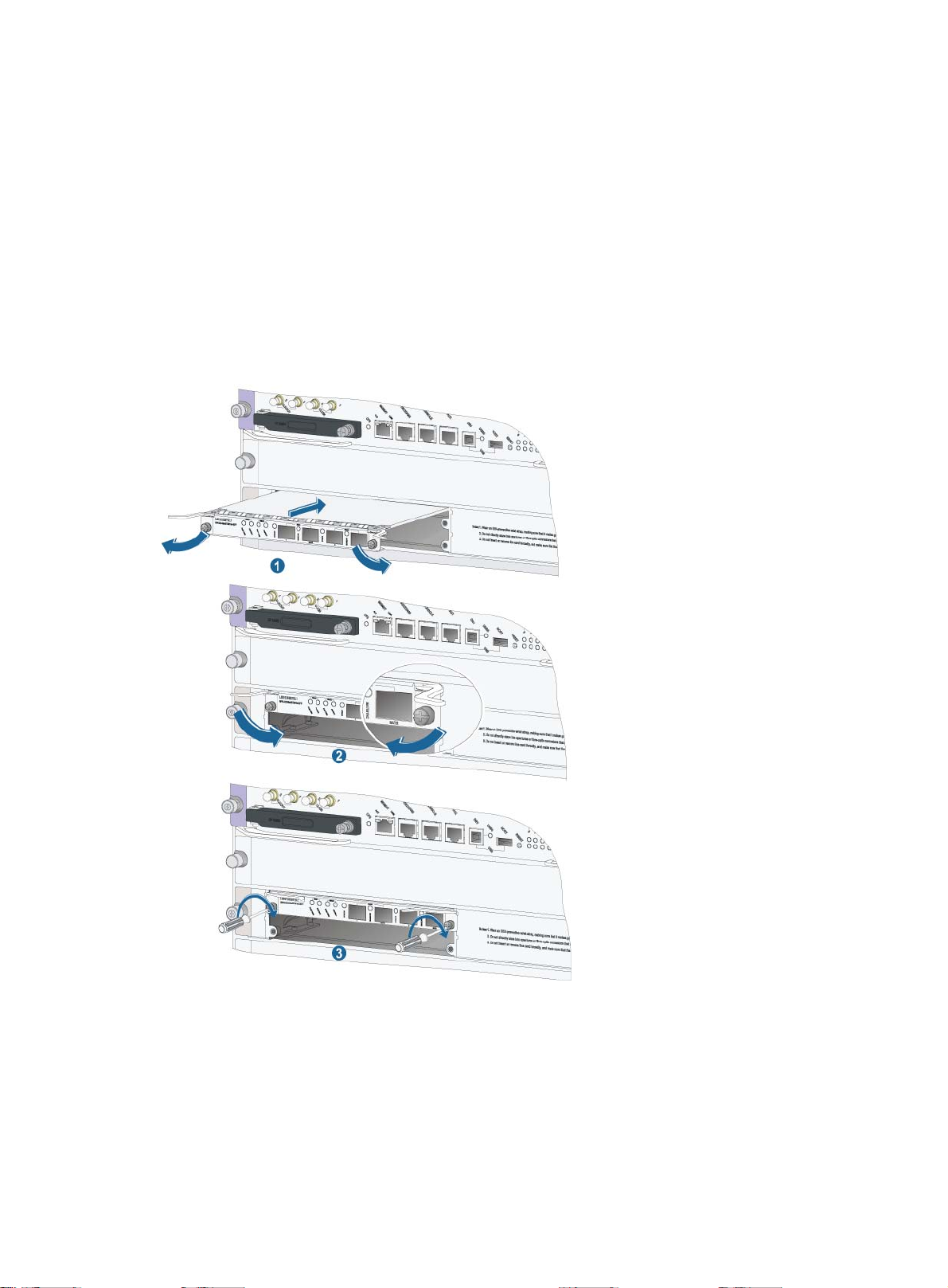
Installing a transceiver module
CAUTION:
During installation, do not touch the golden finger of the SFP module.
The installation procedures for an XFP module and SFP module are similar. The following procedure
uses an SFP module as an example.
To install an SFP module:
1. Put on an ESD-preventive wrist strap, and make sure it makes good skin contact, and is well
grounded.
2. Unpack the SFP module. Close the clasp by pushing it up over the SFP module, and then gently
insert the SFP module into the interface slot until it clicks into place, as shown in Figure 26.
Figure 26 Installing an SFP module
IMPORTANT:
• Do not remove the dust plug of the SFP module port before installing an optical fiber.
• For an SFP module installed with an optical fiber, remove the fiber before you install the SFP module
into the slot.
Connecting an optical fiber
1. Put on an ESD-preventive wrist strap, and make sure it is well grounded.
2. Remove the protective cap from the fiber connector, and use dust free paper and absolute
alcohol to clean the end face of the fiber connector.
3. Connect one end of the fiber to the SFP module of the router.
4. Connect the other end of the fiber to the peer device.
30
Page 36

Figure 27 Connecting an optical fiber to an SFP module
Installing an FMT (optional)
The FMT is installed in a cabinet for winding redundant fibers between the router and other devices.
Confirm the following prerequisites:
• The cabinet is attached.
• The router is installed.
The installation involves the following materials:
• FMT
• M5×10 self-tapping screws (two screws for one FMT)
To install the FMT:
1. Align the FMT and the installation holes on the column of the cabinet.
2. Use a Phillips screwdriver to attach each FMT with two M5×10 self-tapping screws.
Figure 28 Installing the FMT
Cable routing recommendations
31
Page 37

CAUTION:
Do not bind cables at the air exhaust vent to prevent the cables from aging too fast. For more
information, see "Cable management."
Interface cables and power cables should be routed separately. Proper cable routing can improve
efficiency by facilitating installation and removal of fan trays, the PEM, and other components.
Follow these recommendations when you route cables:
• Interface cables are routed through the cable management brackets on the left and right sides of
the chassis and bound at cabling racks on chassis sides, depending on the available equipment
room condition.
• Put all data signal cable adapters neatly under the chassis (instead of any places outside the
chassis in case of unexpected damages).
• The power cables run along the left-rear of the chassis and out of the chassis either from the
chassis top or the raised floor depending on the equipment room conditions (power distribution
cabinet, lightning protection box, and connector strip, etc.) of the exchange office.
• Attach cables as close to the router as possible. The cables between the attachment point and
router interfaces must be bound loosely.
• Long cables can be bound with cable ties. Do not bind cables at the air exhaust vent to prevent
the cables from aging too fast. For more information, see "Appendix E Cable management."
• To identify cables, you can stick labels on them. For more information, see "Appendix F
Engineering labels for cables."
32
Page 38

Hardware management
This chapter describes the hardware management functions of the router.
Displaying electrical label data
Electrical label data is also called permanent configuration data or archive information, which is
written to the storage component of a card during device debugging or testing. The information
includes name of the card, card serial number, and vendor name.
Use the display device manuinfo command to display the electronic label data for your router,
including the card name, serial number, MAC address, manufacturing date, and vendor name.
# Display the electrical label data for the card in slot 3 on your router.
<Sysname> display device manuinfo slot 3
Slot 3:
DEVICE_NAME : SPC-1010-II
DEVICE_SERIAL_NUMBER : 210231A0E50103000002
MAC_ADDRESS : 000f-e200-5600
MANUFACTURING_DATE : 2011-02-28
VENDOR_NAME : HP
Slot 3 Subslot 1:
DEVICE_NAME : PIC-TCP8L
DEVICE_SERIAL_NUMBER : 210231A85JH105000015
MAC_ADDRESS : NONE
MANUFACTURING_DATE : 2010-05-24
VENDOR_NAME : HP
NOTE:
The output depends on your router model.
Displaying card information
Use the display device command to display your router's card information, including the slot number,
card type, card status, and software version.
# Display summary information for all cards on your router.
<Sysname> display device
Slot No. Brd Type Brd Status Software Version
0 SR02SRP2F3 Master A8800-CMW520-R3342
1 NONE Absent NONE
2 NONE Absent NONE
3 SPE-1010-II Normal A8800-CMW520-R3342
Sub1 PIC-TCP8L Normal
4 NONE Absent NONE
5 NONE Absent NONE
33
Page 39

6 NONE Absent NONE
p
Table 10 Command output
Field Descri
Slot No. Slot number of a card.
Hardware type of a card:
Specific card model, such as SPE-1010-II, which is the same as the mark on the card.
Brd Type
• NONE—No card is in the slot.
tion
• UNKNOWN—The card is not supported by the software version and cannot start
normally.
Card status:
• Absent—No card is in the slot.
• Master—The card is an AMB.
Brd Status
• Slave—The card is a SMB.
• Normal—The card is an interface card and operates properly.
• Fault—The card in the slot has not started or fails.
• Off—The card is not powered on.
Software version of the current card:
Software
Version
• Specific software version—The software version of the router.
• NONE—No card is in the slot.
• Mismatched—The software version does not support the card and thus cannot be
uploaded.
Rebooting the router
CAUTION:
• Router reboot can interrupt network services.
• To avoid data loss, use the save command to save the current configurations before a reboot.
• Use the display startup and display boot-loader commands to check that you have correctly set the
startup configuration file and the main system software image file.
You can reboot the router in one of the following ways to recover from an error condition:
• Reboot the device immediately at the CLI.
• At the CLI, schedule a reboot to occur at a specific time and date or after a delay.
• Power off and then re-power on the device. This method might cause data loss, and is the least
preferred method.
Reboot at the CLI is also called hot start. It is mainly used to reboot a router in remote maintenance,
without performing hardware reboot of the router.
For data security, if you reboot the router while the router is performing file operations, the router does
not reboot.
The precision of the rebooting timer is 1 minute. One minute before the rebooting time, the router
prompts "REBOOT IN ONE MINUTE" and reboots in one minute.
To reboot a router:
34
Page 40

Step Command Remarks
p
Optional.
Available in user view.
The precision of the rebooting timer is 1
minute. One minute before the
rebooting time, the router prompts
"REBOOT IN ONE MINUTE" and
1. Reboot a card, or the
whole system immediately.
reboot [ slot slot-number ]
reboots in one minute.
If you do not specify the slot keyword,
or reboot the AMB, the reboot
command reboots the router.
If you are performing file operations
when the router is to be rebooted, the
system does not execute the reboot
command for security purposes.
2. Enable the scheduled
reboot function and
specify a specific reboot
time and date.
3. Enable the scheduled
reboot function and
specify a reboot waiting
time.
schedule reboot at hh:mm
[ date ]
schedule reboot delay { hh:mm
| mm }
Optional.
The scheduled reboot function is
disabled by default.
Available in user view
Optional.
The scheduled reboot function is
disabled by default.
Available in user view
Displaying the router power supply system
Use the display power-supply command to display the power supply system of your router.
<Sysname> display power-supply verbose
Power 1 state: Normal
Power 2 state: Absent
Slot No. Board Power Status
0 POWER ON
3 POWER ON
Table 11 Command output
Field Descri
State of power supply x:
Power x state:
• normal—The power supply is normal.
tion
• absent—The power supply is not in position.
Slot No Slot number of the card.
Power supply status of the card:
Board Power
Status
• power on—The card is properly supplied with power.
• power off—The card is powered off due to user operation or over-temperature
protection.
35
Page 41

Configuring temperature alarm thresholds for a
p
card
Use the following command to set temperature alarm thresholds for a card. When the temperature of
a card exceeds a threshold, the router generates alarm signals.
To configure temperature alarm thresholds for a card:
Step Command Remarks
1. Enter system view.
system-view N/A
2. Configure temperature alarm
thresholds for a card.
temperature-limit slot slot-number hotspot sensor-num
LowerLimit WarningLimit [ AlarmLimit ]
Optional.
Displaying temperature information for a router
Use the display environment command to display the temperature information of the sensors on the
cards, including the current temperature and temperature thresholds.
# Display the temperature information of the cards on the router.
<Sysname> display environment
System temperature information (degree centigrade):
-------------------------------------------------------------------------------
Slot Sensor Temperature LowerLimit WarningLimit AlarmLimit ShutdownLimit
0 hotspot 1 39 0 70 85 N/A
0 hotspot 2 40 20 80 95 N/A
3 hotspot 1 55 -10 60 80 N/A
3 hotspot 2 42 -5 65 85 N/A
Table 12 Command output
Field Descri
tion
Slot Slot number of a card.
Sensor Temperature sensor, where "hotspot" indicates the hotspot temperature sensor.
Temperature Current temperature.
Lower limit Lower limit of temperature.
WarningLimit Upper limit of temperature for warning.
AlarmLimit Upper limit of temperature for alarming.
ShutdownLimit Upper limit of temperature for shutting down the router (currently not supported).
Configuring in-service hardware failure diagnosis
A hardware failure may cause traffic forwarding failures and service interruption. To improve the
automatic failure detection and handling capabilities of the router, you can configure in-service
hardware failure diagnosis.
36
Page 42

The in-service hardware failure diagnosis includes the detection for chips, cards, and the forwarding
p
service, and automatic fix actions taken for the detected failures.
To configure in-service hardware failure diagnosis:
Step Command Remarks
1. Enter system view.
system-view N/A
Required.
The fix actions taken in case of hardware
failures include:
• Off—Takes no action.
• Warning—Sends warning messages.
2. Enable in-service
hardware failure detection
and configure fix actions
taken in case of hardware
failures.
hardware-failure-detection
{ chip | board | forwarding }
{ off | warning | reset |
isolate }
• Reset—Resets the failed card.
• Isolate—Shuts down the failed port,
isolates the failed card, prohibits the
failed card from loaded, or powers off
the failed card to reduce the impact of
the failure to the system.
Currently, the router supports only off and
warning operations. By default, the fix
action taken for all hardware failures is
warning.
After configuring in-service diagnosis, you can use the display hardware-failure-detection command
to check the running information of the feature.
Displaying the operating state of a fan
Use the display fan command to display the operating state of all fans on your router.
<Sysname> display fan
Fan 1 State: Normal
Fan 2 State: Normal
The output above shows that all fans of the router operate normally.
Displaying alarm information for a card
Use the display alarm command to display alarm information for a card.
<Sysname> display alarm
Slot Level Info
0 ERROR Power 2 is absent.
0 ERROR Slot 6 board state is faulty
Table 13 Command output
Field Descri
Alarm severity.
Level
In descending order, the alarm severity levels include ERROR, WARNING,
NOTICE, and INFO.
tion
37
Page 43

Field Description
Info Detailed alarm information.
Slot n board state is
faulty.
Card n is faulty. The reason may be the card is booting or the card fails.
Verifying and diagnosing transceiver modules
Introduction to transceiver modules
There are two types of commonly used transceiver modules, as shown in Table 14. They can be
further divided into optical transceiver modules and electrical transceiver modules based on
transmission medium.
Table 14 Commonly used transceiver modules
Transceiver
type
SFP
XFP
Application scenarios
Generally used for 100M/1000M Ethernet
interfaces, ATM, or POS 155M/622M/2.5G
interfaces
Generally used for 10G Ethernet interfaces and
10 RPR interfaces
Optical
transceiver
module?
Yes Yes
Yes No
Electrical
transceiver
module?
Verifying transceiver modules
To verify transceiver modules, you can use the following commands to view the key parameters of the
transceiver modules, including transceiver module type, connector type, central wavelength of the
laser sent, transfer distance, and vendor name.
To display transceiver module information:
Task Command Remarks
Display key parameters of the transceiver
module in a specified interface.
Display part of the electrical label data for
the transceiver module in a specified
interface.
# Display the main parameters of the transceiver module plugged in interface GigabitEthernet 3/1/1.
<Sysname> display transceiver interface Gigabitethernet 3/1/1
GigabitEthernet3/1/1 transceiver information:
Transceiver Type : 1000_BASE_SX_SFP
Connector Type : LC
Wavelength(nm) : 850
Transfer Distance(m) : 550(50um),270(62.5um)
display transceiver interface
[ interface-type interface-number ]
display transceiver manuinfo
interface [ interface-type interface-
number ]
Available for all
transceiver modules.
Available for all
transceiver modules.
38
Page 44

Digital Diagnostic Monitoring : YES
p
p
Vendor Name : HP
Ordering Name : JD118B
Table 15 Command output
Field Descri
transceiver
information
Transceiver Type Transceiver type
Connector Type
Transceiver information
Type of connector:
• Optical connectors, including SC (SC connector, developed by NTT) and LC (LC
tion
connector, 1.25 mm/RJ-45 optical connector developed by Lucent).
• Other connectors, including RJ-45 and CX 4.
• Optical transceiver module—Central wavelength of the laser sent, in nm. If the
Wavelength(nm)
transceiver module, for example, 10GBASE-LX4, supports multiple wavelengths,
every two wavelength values are separated by a comma.
• Electrical transceiver module—Displayed as N/A.
Transfer distance, where xx represents km for single-mode transceiver modules and m
for other transceiver modules. If the transceiver module supports multiple transfer
medium, every two values of the transfer distance are separated by a comma. The
corresponding transfer medium is included in the bracket following the transfer
Transfer
distance(xx)
distance value. The following are the transfer media:
• 9 μ—9/125 μ single-mode optical fiber
• 50 μ—50/125 μ multi-mode optical fiber
• 62.5 μ—62.5/125 μ multi-mode optical fiber
• TP—Twisted pair
• CX4—CX4 cable
Digital Diagnostic
Monitoring
Whether the digital diagnosis function is supported:
• YES—Supported
• NO—Not supported
Vendor Name
Ordering Name
Name of the vendor who manufactures or customizes the transceiver module.
Transceiver module model.
# Display part of the electrical label data for the transceiver modules in a specified interface.
<Sysname> display transceiver manuinfo interface Gigabitethernet 3/1/1
GigabitEthernet3/1/1 transceiver manufacture information:
Manu. Serial Number : XXXXXXXXXXXXXXXXXX
Manufacturing Date : 2008-09-01
Vendor Name : HP
Table 16 Command output
Field Descri
Manu. Serial Number Serial number of the transceiver module.
Manufacturing Date Manufacturing date of the transceiver module.
Vendor Name Name of vendor who customizes the transceiver module.
tion
39
Page 45

Diagnosing transceiver modules
The device provides the alarm function and digital diagnosis function for transceiver modules. When
a transceiver module fails or inappropriately work, you can check for alarms present on the
transceiver module to identify the fault source or examine the key parameters monitored by the digital
diagnosis function, including the temperature, voltage, laser bias current, TX power, and RX power.
To display alarm information or fault detection parameters for a transceiver module:
Task Command Remarks
Display the current alarm information of the
transceiver module in a specified interface
Display the currently measured values of the
detection parameters of the transceiver module
in a specified interface
display transceiver alarm
interface [ interface-type
interface-number ]
display transceiver diagnosis
interface [ interface-type
interface-number ]
Available for all
transceiver modules.
Available for all
transceiver modules.
# Display the alarm information of the transceiver module plugged in GigabitEthernet 3/1/1.
<Sysname> display transceiver alarm interface GigabitEthernet 3/1/1
GigabitEthernet3/1/1 transceiver current alarm information:
RX loss of signal
Table 17 Command output
Field Remarks
SFP
RX loss of signal Receive (RX) signal is lost.
TX fault TX fault.
RX power high RX power is high.
RX power low RX power is low.
TX power high TX power is high.
TX power low TX power is low.
TX bias high TX bias current is high.
TX bias low TX bias current is low.
Temp high Temperature is high.
Temp low Temperature is low.
Voltage high Voltage is high.
Voltage low Voltage is low.
Transceiver info I/O error Transceiver information read and write error.
Transceiver info checksum error Transceiver information checksum error.
Transceiver type and port configuration
mismatch
Transceiver type not supported by port
hardware
Transceiver type does not match port configuration.
Transceiver type is not supported on the port.
40
Page 46

Field Remarks
XFP
RX loss of signal RX signal is lost.
RX not ready RX is not ready.
RX CDR loss of lock RX clock cannot be recovered.
TX fault TX fault.
TX not ready TX is not ready.
TX CDR loss of lock TX clock cannot be recovered.
Module not ready Module is not ready.
APD supply fault Avalanche Photo Diode (APD) supply fault.
TEC fault Thermoelectric Cooler (TEC) fault.
Wavelength unlocked
Wavelength of optical signal exceeds the manufacturer's
tolerance.
RX power high RX power is high.
RX power low RX power is low.
TX power high TX power is high.
TX power low TX power is low.
TX bias high TX bias current is high.
TX bias low TX bias current is low.
Temp high Temperature is high.
Temp low Temperature is low.
Voltage high Voltage is high.
Voltage low Voltage is low.
Transceiver info I/O error Transceiver information read and write error.
Transceiver info checksum error Transceiver information checksum error.
Transceiver type and port configuration
mismatch
Transceiver type not supported by port
hardware
Transceiver type does not match port configuration.
Transceiver type is not supported on the port.
# Display the currently measured values of the fault detection parameters for the transceiver module
plugged in interface GigabitEthernet 3/1/1.
<Sysname> display transceiver diagnosis interface Gigabitethernet 3/1/1
GigabitEthernet3/1/1 transceiver diagnostic information:
Current diagnostic parameters:
Temp(°C) Voltage(V) Bias(mA) RX power(dBM) TX power(dBM)
36 3.31 6.13 -35.64 -5.19
41
Page 47

Table 18 Command output
p
Field Descri
Transceiver diagnostic
information
Current diagnostic
parameters
Temp.(°C) Digital diagnosis parameter-temperature, in °C, with the precision to 1°C
Voltage(V) Fault detection parameter-voltage, in V, with the precision to 0.01 V
Bias(mA) Fault detection parameter-bias current, in mA, with the precision to 0.01 mA
RX power(dBM) Fault detection parameter-RX power, in dBM, with the precision to 0.01 dBM.
TX power(dBM) Fault detection parameter-TX power, in dBM, with the precision to 0.01 dBM
Fault detection information of the transceiver module plugged in the interface
Current fault detection parameters
tion
42
Page 48

Troubleshooting
This chapter describes how to troubleshoot router installation failures.
The router power supply system, fans, and cards have multiple LEDs to help you locate failures.
Configuration terminal problems
If the configuration environment setup is correct, the configuration terminal displays boot information
when the router is powered on. If the setup is incorrect, the configuration terminal displays nothing or
garbled text.
No terminal display
If the configuration terminal displays nothing when the router is powered on, verify that:
• The power supply system works correctly.
• The MPU works correctly.
• The console cable has been connected to the console port of the MPU.
If no problem is found, the following reasons may apply:
• The console cable is connected to an incorrect serial interface. (The the serial interface in use is
not the one set on the terminal.)
• The properties of the terminal are incorrect. You must configure the console terminal as follows:
set Bits per second to 9600, Data bits to 8, Parity to None, Stop bits to 1, Flow control to None,
and Terminal Emulation to VT100.
• The console cable fails. If the console cable fails, you can replace a cable.
Garbled terminal display
If terminal display is garbled, verify that the following settings are configured for the terminal (for
example, HyperTerminal):
• Baud rate—9600
• Data bits—8
• Parity—none
• Stop bits—1
• Flow control—none
• Emulation—VT100
Power supply system failure
The following tables provide LED information for AC and DC power supplies.
43
Page 49

Table 19 AC power supply LED
LED Status Description
Input
Output
Fault
Steady green Power is being input correctly.
Off
Steady green The power supply is outputting power correctly.
Off The power supply has an output voltage error or is absent.
Steady red
Off The power module is operating correctly or absent.
The power supply is absent or has input voltage error.
The power supply is experiencing an overvoltage, overcurrent, or overtemperature condition.
Table 20 DC power supply LEDs
LED Status Description
IN (input)
OUT
(output)
FAIL (fault)
Steady green
Off
Steady green The power supply is outputting power correctly.
Off The power supply has an output voltage error or is absent.
Steady red
Off The power supply is operating correctly or absent.
Power is being correctly input.
The power supply is absent or has an input voltage error.
The power supply is experiencing an overvoltage, overcurrent, or overtemperature condition.
When the input/output LEDs are off or the fault LEDs are on, the power supply does not work properly.
To troubleshoot the power supply system:
1. Examine the power cable connections. If a power cable is loose, plug it in.
2. Replace the power cable and verify that the LEDs are normal.
3. Examine the power supply installation. If the power supply is not seated properly, reinstall the
power supply so that it makes close contact with the router.
4. Examine the power source. Make sure the power source is operating properly and provides a
normal voltage.
5. Determine whether the power supply has encountered output short circuit, output over-current,
output over-voltage, input under-voltage, or over-temperature problems.
6. Power off the router, plug the power supply into an empty power supply slot, and verify that the
power supply is operating properly. If the power supply is operating properly, the power
supply slot may have failed. Otherwise, proceed to the next step.
7. Plug a new power supply of the same model into the same power supply slot and connect it to
the same power source. If the new power supply is operating properly, the old power supply
fails. Contact the agents to replace the old power supply.
Fan failure
The following tables provide fan LED information.
44
Page 50

Table 21 Fan LEDs
LED Status Description
RUN
Off
Steady green
Off
ALM
Steady red
When the RUN LED is off or the ALM LED is on, the fan tray fails. To troubleshoot the fan tray:
1. If both LEDs are off, examine the power supply to make sure it is operating properly. For more
information, see "Power supply system failure."
2. Check for blockage of the air intake and exhaust vents on the chassis. If they are blocked,
clean them to keep the air flowing.
3. Unplug the fan tray and plug it in again.
4. Plug a spare fan tray into the slot. If the spare fan tray works properly, you can conclude that
the old fan tray has failed.
5. If there is still a failure, contact HP Support.
MPU failure
The appearance of routers varies by model. Figure 29 uses SR02SRP1F3 as an example.
Figure 29 MPU LEDs
The fan tray has failed.
The fan tray is operating properly.
The fan tray is in a normal state.
The fan tray is faulty.
(1) CF card status LED
(CFS)
(4) MPU status LED (SFS) (5) MPU status LED (ACT) (6) MPU status LED (RUN)
(7) MPU status LED (ALM) (8) LPU status LED (RUN) (9) LPU status LED (ALM)
(2) Network management port LED
(ACT)
(3) Network management port LED
(LINK)
When the MPU is operating properly, the RUN LED blinks and the ALM LED is off. When the RUN
LED is off, the MPU fails. To troubleshoot the MPU:
1. Verify that the power supply is operating properly. For more information, see "Power supply
system failure."
45
Page 51

2. Press the MPU RESET button to reset the MPU, and then verify that the corresponding RUN LED
is on.
3. Make sure the MPU is seated properly. You can unplug the MPU, plug it in again, and make
sure the MPU is seated properly.
4. If the router has empty MPU slots, plug the MPU into an empty slot and make sure the MPU is
operating properly.
5. If the ALM LED is on, the MPU reports alarms. Use the display alarm command to locate and
resolve the failures.
6. If there is still a failure, contact HP Support.
LPU failure
When the LPU is operating properly, the RUN LED blinks and the ALM LED is off. At the same time,
the RUN LED on the LPU blinks and the ALM LED on the LPU is off.
When the RUN LED is off, the LPU fails. To troubleshoot the LPU:
1. Verify that the MPU is operating properly. For more information, see "MPU failure."
2. Use the display device command to determine if the software version is compatible with the LPU
in the current slot. If not, upgrade the software to a compatible version.
3. Calculate the overall power consumption and make sure the power supply can provide enough
power.
4. Verify that the LPU is seated properly. You can unplug the LPU, plug it in again, and make sure
it is seated properly.
5. If the router has empty LPU slots, plug the LPU into an empty slot and make sure the LPU is
operating properly.
6. If there is still a failure, contact HP Support.
Interface failure
The MPU and LPU have LINK LEDs that indicate the interface status. When the link of an interface is
present and operating properly, the corresponding LINK LED is on.
If the LINK LED of an interface is off, the interface or the connecting cable may fail. To troubleshoot
the interface:
1. Make sure the MPU or LPU that provides the interface resides is operating properly. For more
information, see "MPU failure" or "LPU failure."
2. Examine the cable connection of the interface. For information on connecting a copper or fiber
Ethernet interface, see "Connecting the router to the network."
3. Verify that the cable is not broken. Use the cable to connect two interfaces of the same type that
are operating properly. If the LEDs of the two interfaces are on, the cable is normal. Otherwise,
the cable fails. Use a compliant cable to connect the interface.
4. If the interface uses a transceiver module, make sure the interface type is compatible with the
transceiver module and that the transceiver module is compatible with the cable. For more
information, see "Transceiver modules."
5. If the interface uses a transceiver module, replace the module with a normal transceiver module.
If the problem persists, you can rule out the transceiver module failure.
46
Page 52

6. If the LED is for a copper or fiber combo port, make sure the port has been activated. If not, use
W
the combo enable { copper | fiber } command to activate it. If the LED is still off, the interface or
the link has failed.
7. Use the display interface command to determine if the interface is UP. If the interface is not UP,
use the undo shutdown command to bring up the interface.
8. Make sure the speed and duplex settings of the link interfaces are the same, and the interfaces
work properly together.
9. If there is still a failure, contact HP Support.
NOTE:
hen an interface fails, if the router has an idle interface of the same type, you can plug the cable into
the idle interface.
Technical support
If there are still failures, contact HP Support. Before contacting customer service, prepare the following
information to help the agents solve the problem as quickly as possible:
• Arrival time of the router
• Serial number of the chassis (located on a label on the rear panel)
• Software version (which you can view by using the display version command)
• Maintenance agreement or warranty card
• Brief problem description
• Brief explanation of the troubleshooting measures that have been taken
You can contact customer service through the HP website: http://www.HP.com
.
47
Page 53

Replacement procedures
W
This chapter provides information about replacing components on the router.
Replacing a power supply system
ARNING!
• Power supplies for the router are hot-swappable. When hot-swapping a power supply, make sure the
other power supply is operating properly. When installing and replacing a power supply with the
router powered on, pay attention to the operation procedures and electricity safety issues. To avoid
injury, do not touch any wires, terminals, or parts with a high-voltage hazard sign.
• Hold the power supply by the bottom when moving it. Do not lift the module by the handle.
To prepare for the replacement:
1. Put on an ESD-preventive wrist strap and make sure it makes good skin contact and is well
grounded.
2. Make sure the power switch of the DC or AC power supply is in the OFF position before
removing it.
3. Remove the cables connected to the DC or AC power supply.
Replacing a DC power supply
1. Use a Phillips screwdriver to loosen the captive screws on both sides of the power supply,
remove the air filter frame of the power supply, and pull out the handle of the power supply.
2. Supporting the bottom of the power supply with one hand and holding the power supply
handle with the other hand, gently pull the DC power supply out along the slide rails.
Put the removed power supply on an antistatic mat or its original shipping materials.
3. Remove the air filter frame of the new power supply, and pull out the handle.
HP recommends that you place a removed module in an antistatic bag or its original shipping
materials.
4. Slowly push the new power supply into the slot along the slide rails until the rear side of the
power supply has close contact with the backplane.
5. Use a Phillips screwdriver to fasten the captive screws on both sides of the power supply panel,
and install the air filter frame of the power supply.
48
Page 54

Figure 30 Replacing a DC power supply
(A) DC power supply to be removed (B) DC power supply to be installed
Replacing an AC power supply
1. Pull the handle of the power supply downward to the unlock position. Gently move the power
supply to separate it from the backplane of the power frame.
2. Supporting the bottom of the power supply with one hand and holding the power supply
handle with the other hand, gently pull the power supply out.
Put the removed power supply on an antistatic mat or into the original shipping materials.
NOTE:
If the power frame is installed with two AC power supplies, repeat steps 1 and 2 to remove the other
power supply.
3. Use a Phillips screwdriver to loosen the captive screws on both sides of the power frame.
4. Supporting the bottom of the power frame with one hand and holding the power frame handle
with the other hand, gently pull the AC power frame out along the slide rails.
Place a removed power frame in an antistatic bag or its original shipping materials.
49
Page 55

5. Slowly push a new power frame into the slot along the slide rails until the rear of the power
frame has close contact with the backplane.
6. Use a Phillips screwdriver to fasten the captive screws on both sides of the power frame.
7. Pull the handle of a power supply downward to the unlock position.
8. Gently push the power supply into the specified slot of the AC power frame until the rear of the
power supply has close contact with the AC power frame backplane.
9. Push the handle upward so that it locks the power supply in place.
Figure 31 Replacing an AC power frame and an AC power supply
(A) AC power frame to be removed (B) AC power frame to be installed
50
Page 56

Cleaning a power supply air filter
To ensure proper ventilation of the power supply, HP recommends that you clear the air filter monthly.
The NEPS3500-A power frame does not have an air filter.
To clean the power supply air filter:
1. Using your thumb and index finger to hold the upper and lower edges of the air filter frame,
gently remove the air filter frame. Pull the black air filter out of the air filter frame.
Figure 32 Removing a power supply air filter
2. Use water to gently wash the air filer, and then air-dry it.
When you wash the air filter, do not rub it.
3. Put the black air filter into the air filter frame. Using the thumb and index finger to hold the
upper and lower edges of the air filter frame, gently insert the air filter frame into the power
supply.
Figure 33 Installing a power supply air filter
Replacing a card
LPUs and MPUs for the router are hot-swappable. Replacement procedures for these types of cards
are similar. This section describes how to replace an MPU.
To prepare for the replacement:
1. Put on an ESD-preventive wrist strap and make sure the wrist strap makes good skin contact
and is well grounded.
51
Page 57

2. Remove the blank panel (if any) from the slot to be used. Keep the removed blank panel and
protection cover for future use.
3. Unpack the card to be installed. If the card has a protection cover, remove it. Keep the
removed protection cover for future use.
Figure 34 Removing the protection cover
To replace a card:
1. Put on an ESD-preventive wrist strap and loosen the captive screws on both sides of the card to
be removed.
2. Pull the ejector levers outward to separate the card from the backplane of the chassis.
3. Slowly pull out the card along the slide rails. Put the removed card on an antistatic mat or into
its original shipping materials.
4. Pivot the ejector levers outward. Supporting the card with both hands, gently insert the card into
the slot along the slide rails.
5. Push the ejector levers inward to ensure close contact between the card and the backplane.
6. Position the screws in the holes and fasten them with a screwdriver.
52
Page 58

Figure 35 Replacing a card
W
Replacing a subcard
CAUTION:
hen the router is operating, you must remove the SPE card before removing or installing the subcard.
Subcards do not support hot swapping. Replace a subcard using one of the following methods:
• Power off the router, and then remove or install the subcard on the SPE card.
• When the router is operating, remove the SPE card, replace the subcard on the SPE card, and
then install the SPE card to the router.
To replace a subcard when the router is powered off:
1. Put on an ESD-preventive wrist strap and loosen the captive screws on the subcard to be
replaced.
2. Pull the ejector levers outward to separate the subcard from the SPE card.
3. Slowly pull out the subcard along the guide rails, as shown in Figure 36.
4. Put the removed subcard on an antistatic mat or in the original package.
5. Gently plug the subcard (with the right side up) along the slide rails. When the ejector levers of
the subcard reach the panel of the SPE card, stop sliding the subcard. Push the panel of the
subcard and move the ejector levers of the subcard inward when the subcard reaches the SPE
card, so that the panel of the subcard is on the same plane as the panel of the SPE card.
6. Use a Phillips screwdriver to fasten the captive screws on the subcard to tighten the subcard.
53
Page 59

Figure 36 Replacing a subcard
(A) Subcard to be removed (B) Subcard to be installed
Replacing a fan tray
CAUTION:
Fan trays are hot-swappable. If you replace a fan tray with the router running, pull out the fan tray
after it stops rotating and keep your hands away from the spinning fan blades. To avoid injury, do not
touch any wires, terminals, or parts with a high-voltage hazard sign.
Replacing a fan tray for an A8805/A8812
The fan trays for the A8805/A8812 routers are installed vertically, and the replacement procedures
are the same.
To replace a fan tray for an A8805/A8812:
1. Put on an ESD-preventive wrist strap and loosen the captive screws on the fan tray.
2. Holding the fan tray handle with one hand and supporting the fan tray bottom with the other
hand, pull out the fan tray along the slide rails. Put the removed fan tray on an antistatic mat or
into its original shipping materials. To ensure normal operation of the router, do not keep the
router working without a fan tray for any length of time.
54
Page 60

3. Gently insert the new fan tray into the fan tray slot along the slide rails until it has close contact
with the backplane.
4. Use a Phillips screwdriver to fasten the captive screws on both sides of the fan tray panel.
Figure 37 Removing a fan tray for an A8805/A8812
Replacing a fan tray for an A8808
The fan tray for an A8808 is installed horizontally.
To replace a fan tray for an A8808:
1. Use your thumb to press the fan tray button, and then pull the fan tray partway out.
2. Holding both sides of the fan tray, pull out the fan tray along the slide rails. Put the removed fan
tray on an antistatic mat or into its original shipping materials.
3. Insert a new fan tray into the fan tray slot along the slide rails until it has close contact with the
backplane.
55
Page 61

Figure 38 Replacing a fan tray for an A8808
A
(A) Fan tray to be removed (B) Fan tray to be installed
Replacing a chassis air filter
CAUTION:
Clean the air filters every three months to guarantee adequate ventilation and avoid over-temperature.
chassis air filter is not shipped with the router. You can order one if needed.
Replacing chassis air filters for an A8808
1. Use a Phillips screwdriver to remove the captive screws on the front and rear air filters, as
shown in Figure 39.
2. Remove the front and rear air filters from the chassis, as shown in Figure 39.
3. Install the cleaned air filters to the router.
56
Page 62

Figure 39 Replacing chassis air filters for an A8808
Replacing an air filter for an A8805/A8812
1. Loosen the captive screws on the air filter, as shown in Figure 40.
2. Grasping the captive screws on the air filter, slowly pull the air filter out of the chassis, as
shown in Figure 40.
3. Install the cleaned air filter on the router.
Figure 40 Replacing an air filter for an A8805
Replacing a CF card
CAUTION:
Do not remove the CF card when the router is booting or the CF card LED is flashing. Otherwise, the
file system on the hardware or CF card might be damaged.
57
Page 63

Figure 41 CF card slot
A
(1) CF card cover (2) CF card eject button
(3) CF card (4) CF card LED
The CF card is installed on the MPU of the router. If the CF card memory is insufficient or the CF card
is damaged, follow these steps to replace the card. Before inserting the CF card, make sure the eject
button is all the way into the slot and does not project from the panel.
1. Examine the CF card LED status.
{ If the LED is on, you cannot remove the CF card. You must unmount the CF card using the CLI
and wait until the CF card LED is off before removing the CF card.
<Sysname> umount cfa0:
{ If the LED is flashing, the CF card is reading and writing data. In this case, you cannot remove
the CF card. Wait until the CF card LED stops flashing before removing it.
{ If the LED is off, the CF card has been unmounted and you can remove it.
NOTE:
fter you execute the umount cf command, if you want to continue to use the CF card, execute the
mount cf command in user view to load the CF card again. For more information about the umount
and mount commands, see
2. Use a Phillips screwdriver to loosen the screw on the right side of the CF card cover, and then
HP A8800 Routers Fundamentals Command Reference
.
pull the CF card cover outward.
3. Press the eject button of the CF card reader. The reader ejects the card partway out of the slot.
Remove the CF card from the reader and put it in an antistatic bag or its original shipping
materials.
4. Push the new CF card all the way into the CF card slot. The eject button will project out.
5. Push the CF card cover inward.
6. Use a Phillips screwdriver to fasten the screw on the right side of the CF card cover.
58
Page 64

Figure 42 Replacing a CF card
W
Replacing a transceiver module
CAUTION:
hen installing or removing an SFP transceiver module, do not touch the golden finger.
The replacement procedures for XFP and SFP transceiver modules are similar. This section uses an SFP
transceiver module as an example.
To replace a transceiver module:
1. Put on an ESD-preventive wrist strap, ensuring that the wrist strap makes good skin contact and
is grounded.
2. Remove the optical fibers from the SFP transceiver module, pivot the clasp down to the
horizontal position, and then pull SFP the transceiver module out of the socket as shown
in Figure 43.
3. Put the removed SFP transceiver module in an antistatic bag or its original shipping materials.
4. Unpack a new SFP transceiver module, pivot the clasp of the SFP transceiver module upward to
the vertical position so that it catches a knob on the top of the SFP transceiver module, and then,
holding both sides of the SFP transceiver module, gently push the SFP transceiver module into
the socket until it has close contact with the socket (you can feel that the top and bottom spring
tabs catch in the socket), as shown in Figure 44.
5. Connect the optical fibers to the new SFP transceiver module.
59
Page 65

Figure 43 Removing an SFP transceiver module
Figure 44 Installing an SFP transceiver module
60
Page 66

Hardware specifications
p
Environmental requirements
Table 22 Environment requirements
Tem
erature Range
Long term: 0°C to 45°C (32°F to 113°F)
Operating temperature
Short term: –10°C to +55°C (14°F to 131°F) (no more than 96 hours of
continuous operation in less than 15 days in one year)
Operating humidity
(noncondensing)
Storage temperature –40°C to +70°C (–40°F to +158°F)
Operating altitude
5% to 95%
Available altitude: ≤ 4000 m (13123.36 ft)
Certificated altitude: ≤ 3000 m (9842.52 ft)
Technical specifications
The diagrams in this document are for illustration only. AC-powered chassis are used as an example.
Chassis
A8805 chassis views
You can install one or two power supplies, but you cannot mix AC and DC power supplies. Figure 45
shows the A8805 with four AC power supplies installed in the two AC power frames.
61
Page 67

Figure 45 A8805 front view
(1) ESD-preventive wrist strap port (2) MPU slots (slots 0 and 1) (3) LPU slots (slots 2 to 6)
(4) Power supply slots (5) PoE power entry module (reserved)
62
Page 68

Figure 46 A8805 rear view
(1) Rear cover handle (2) Grounding screw (3) Fan tray
A8808 chassis views
You can install one or two power supplies, but do not intermix AC and DC power supplies. In this
figure, four AC power supplies are installed in the two AC power frames.
63
Page 69

Figure 47 A8808 front view
(1) Fan tray (2) MPU slots (slots 4 and 5) (3) LPU slots (slots 0 to 3, 6 to 9)
(4) Cable management
bracket
(7) ESD-preventive wrist strap port
(5) Power supply slots (6) PoE power entry module (reserved, currently
not available)
64
Page 70

Figure 48 A8808 rear view
(1) Air filter (2) Grounding screw (3) Rear cover handle
65
Page 71

A8812 chassis views
You can install one or two power supplies, but intermixing of AC and DC power supplies is not
allowed. In this figure, four AC power supplies are installed in the two AC power frames.
Figure 49 A8812 front view
(1) ESD-preventive strap port (2) LPU slots (slots 0 to 5, 8 to 13) (3) MPU slots (slots 6 and 7)
(4) Power supply slots (5) PoE power entry module (reserved, currently not available)
66
Page 72

Figure 50 A8812 rear view
(1) Rear cover handle (2) Grounding screw (3) Fan tray
67
Page 73

Chassis specifications
p
g
Table 23 Chassis specifications
Model
A8805
A8808
A8812
Max power
consum
2040 W (AC)
1795 W (DC)
2916 W (AC)
2671 W (DC)
4248 W (AC)
4003 W (DC)
NOTE:
RU is a unit of measure that describes the hei
(1.75 in).
Cooling system
Fan trays
tion
Weight Dimensions (H × W × D) Height (RU)
Net weight: 40 kg (88.18 lb)
Full configuration: ≤ 85 kg
(187.39 lb)
Net weight: 58 kg (127.87 lb)
Full configuration: ≤ 110 kg
(242.50 lb)
Net weight: 60 kg (132.28 lb)
Full configuration: ≤ 120 kg
(264.55 lb)
486 × 442 × 450 mm
(19.13 × 17.40 × 17.72 in)
975 × 436 × 450 mm
(38.39 × 17.17 × 17.72 in)
753 × 442 × 450 mm
(29.65 × 17.40 × 17.72 in)
11 RU
22 RU
17 RU
ht of a device mounted in a rack. 1 RU equals 44.45 mm
The router uses fan trays for heat dissipation. The fan trays are hot-swappable. You can replace fan
trays without powering off the router. The fan trays can monitor the operating status of fans,
automatically adjust fan rotation speed to decrease noise and improve energy efficiency, and display
alarms.
IMPORTANT:
The A8805 and the A8812 routers use the same type of fan trays, but the A8808 router uses a
different type of fan tray.
68
Page 74

Figure 51 Fan trays
(1) RUN LED (2) ALM LED
Table 24 Fan LEDs
LED Status Description
RUN
ALM
Off The fan tray has failed.
Steady green The fan tray is working correctly.
Off
Steady red
Table 25 Fan tray specifications
Fan tray Power consumption Net weight Dimensions (H × W × D)
Fan tray for A8805/A8812 12 W to 90 W 3.97 kg (8.75 lb)
Fan tray for A8808 16 W to 130 W
NOTE:
The A8805/A8812 uses a vertical fan tray slot; the A8808 adopts the horizontal fan tray slot.
A8805 and A8812 airflow
The chassis and power supplies for the A8805 and A8812 use separate air aisles. The airflow for the
power supply section at the bottom is from front to rear; the airflow for the chassis is from left to right,
as shown in Figure 52.
The fan tray is in a normal state.
The fan tray is faulty.
4.85 kg (10.69
lb)
299.5 × 95 × 412.7 mm
(11.79 × 3.74 × 16.25 in)
64 × 403.2 × 405.4 mm
(2.52 × 15.87 × 15.96 in)
69
Page 75

Figure 52 A8805 airflow
(1) Chassis air intake (2) Chassis air outlet (3) Power supply air intake (4) Power supply air outlet
A8808 airflow
The chassis and power supplies for the A8808 use separate air aisles. For the power supply section
at the bottom, air flows from front to rear; for the chassis, air flows in through the air intake vents at
the lower rear and front of the chassis, and exhausts out the side air outlets and rear air outlets at the
top of the chassis, as shown in Figure 53.
70
Page 76

Figure 53 A8808 airflow
p
(1) Chassis air intake (2) Chassis air outlet (3) Power supply air intake (4) Power supply air outlet
If you have installed a rear impedance carrier for the A8808, the fan tray cannot pull ambient air in
from the rear but can still blow hot air out the rear.
Card specifications
Table 26 Card specifications
Card model
SR02SRP1F3 52 W to 65 W 3.20 kg (7.05 lb)
SR02SRP2F3 79 W to 95 W 3.50 kg (7.72 lb)
SPC-XP2L 50 W to 60 W 3.10 kg (6.83 lb)
SPC-XP4L 82 W to 95 W 3.30 kg (7.28 lb)
Power
consum
tion
Net weight Dimensions (H × W × D)
40 × 400 × 380 mm (1.57 × 15.75 × 14.96
in)
40 × 400 × 380 mm (1.57 × 15.75 × 14.96
in)
40 × 400 × 380 mm (1.57 × 15.75 × 14.96
in)
40 × 400 × 380 mm (1.57 × 15.75 × 14.96
in)
71
Page 77

Card model
p
Power
consum
tion
Net weight Dimensions (H × W × D)
SPC-GP48L 67 W to 115 W 3.50 kg (7.72 lb)
SPC-GP24L 47 W to 75 W
SPC-GT48L 72 W to 125 W 3.60 kg (7.94 lb)
SPE-1010 80 W to 95 W 4.00 kg (8.82 lb)
SPE-1010-II 80 W to 95 W 3.60 kg (7.94 lb)
SPE-1020 148 W to 165 W 3.90 kg (8.60 lb)
SPE-1020-II 148 W to 165 W 4.40 kg (9.70 lb)
SPE-1010-E 94 W to 107 W 3.60 kg (7.94 lb)
SPE-1020-E 160 W to 200 W 4.50 kg (9.92 lb)
SPE-1010-E-II 94 W to 107 W 3.60 kg (7.94 lb)
5.00 kg (11.02
lb)
40 × 400 × 380 mm (1.57 × 15.75 × 14.96
in)
40 × 400 × 380 mm (1.57 × 15.75 × 14.96
in)
40 × 400 × 380 mm (1.57 × 15.75 × 14.96
in)
40 × 400 × 380 mm (1.57 × 15.75 × 14.96
in)
40 × 400 × 380 mm (1.57 × 15.75 × 14.96
in)
40 × 400 × 380 mm (1.57 × 15.75 × 14.96
in)
40 × 400 × 380 mm (1.57 × 15.75 × 14.96
in)
40 × 400 × 380 mm (1.57 × 15.75 × 14.96
in)
40 × 400 × 380 mm (1.57 × 15.75 × 14.96
in)
40 × 400 × 380 mm (1.57 ×15.75 × 14.96
in)
SPE-1020-E-II 160 W to 200 W 4.50 kg (9.92 lb)
PIC-GP10L 9.27 W to 21 W 0.45 kg (0.99 lb) 18 × 165 × 142 mm (0.71 × 6.50 × 5.59 in)
PIC-GP20R 15.69 W to 25 W 0.70 kg (1.54 lb) 37 × 165 × 142 mm (1.46 × 6.50 × 5.59 in)
PIC-GT20R
PIC-XP1L
PIC-RSP2L 16.79 W to 25 W 0.40 kg (0.88 lb) 18 × 165 × 142 mm (0.71 × 6.50 × 5.59 in)
PIC-RUP1L 14.3 W to 19 W 0.50 kg (1.10 lb) 18 × 165 × 142 mm (0.71 × 6.50 × 5.59 in)
PIC-PSP4L 9.7 W to 18 0.40 kg (0.88 lb) 18 × 165 × 142 mm (0.71 × 6.50 × 5.59 in)
PIC-PUP1L 14.3 W to 19 W 0.50 kg (1.10 lb) 18 × 165 × 142 mm (0.71 × 6.50 × 5.59 in)
PIC-PS2G4L 9.23 W to 16 W 0.40 kg (0.88 lb) 18 × 165 × 142 mm (0.71 × 6.50 × 5.59 in)
PIC-PL2G6L 9.7 W to 18 W 0.40 kg (0.88 lb) 18 × 165 × 142 mm (0.71 × 6.50 × 5.59 in)
PIC-PH2G6L 9.7 W to 17 W 0.40 kg (0.88 lb) 18 × 165 × 142 mm (0.71 × 6.50 × 5.59 in)
PIC-TCP8L 9.7 W to 17 W 0.40 kg (0.88 lb) 18 × 165 × 142 mm (0.71 × 6.50 × 5.59 in)
PIC-ALP4L 30 W to 37 W 0.60 kg (1.32 lb) 37 × 165 × 142 mm (1.46 × 6.50 × 5.59 in)
16.32 W to 23.5
W
12.47 W to 23.7
W
0.65 kg (1.43 lb) 37 × 165 × 142 mm (1.46 × 6.50 × 5.59 in)
0.45 kg (0.99 lb) 18 × 165 × 142 mm (0.71 × 6.50 × 5.59 in)
40 × 400 × 380 mm (1.57 ×15.75 × 14.96
in)
PIC-AHP1L 29.7 W to 36 W 0.60 kg (1.32 lb) 37 × 165 × 142 mm (1.46 × 6.50 × 5.59 in)
PIC-CSP1L 9.6 W to 16 W 0.40 kg (0.88 lb) 18 × 165 × 142 mm (0.71 × 6.50 × 5.59 in)
PIC-CL1G8L 18.13 W to 32 W 0.60 kg (1.32 lb) 37 × 165 × 142 mm (1.46 × 6.50 × 5.59 in)
72
Page 78

Card model
p
PIC-CL2G8L 18.22 W to 33 W 0.65 kg (1.43 lb) 37 × 165 × 142 mm (1.46 × 6.50 × 5.59 in)
PIC-CLS4G4L 30.86 W to 37 W 0.65 kg (1.43 lb) 37 × 165 × 142 mm (1.46 × 6.50 × 5.59 in)
Power
consum
tion
Net weight Dimensions (H × W × D)
PICCHS1G4L
PIC-ET8G8L
PIC-ET32G2L 18 W to 22 W 1.25 kg (2.76 lb) 37 × 165 × 142 mm (1.46 × 6.50 × 5.59 in)
IM-NAT 94 W to 107 W 2.90 kg (6.39 lb)
IM-NAT-II 94 W to 107 W
IM-NAM 94 W to 107 W
IM-FW-II 84.88 W to 120 W 3.52 kg (7.76 lb)
IM-SSL 91.82 W to 110 W 3.52 kg (7.76 lb)
IM-LB 84.88 W to 120 W 3.52 kg (7.76 lb)
IM-NAM-II 94 W to 107 W 3.40 kg (7.50 lb)
24 W to 30 W 0.60 kg (1.32 lb) 37 × 165 × 142 mm (1.46 × 6.50 × 5.59 in)
22.91 W to 28.4
W
0.60 kg (1.32 lb) 37 × 165 × 142 mm (1.46 × 6.50 × 5.59 in)
40 × 400 × 380 mm (1.57 × 15.75 × 14.96
in)
3.40 kg (7.50 lb)
3.40 kg (7.50 lb)
40 × 400 × 380 mm (1.57 × 15.75 × 14.96
in)
40 × 400 × 380 mm (1.57 × 15.75 × 14.96
in)
40 × 400 × 380 mm (1.57 × 15.75 × 14.96
in)
40 × 400 × 380 mm (1.57 × 15.75 × 14.96
in)
40 × 400 × 380 mm (1.57 × 15.75 × 14.96
in)
40 × 400 × 380 mm (1.57 ×15.75 × 14.96
in)
For more information about the router card LEDs, see "LEDs." For more information about the router
cards, see the appropriate card datasheet.
MPU specifications
CAUTION:
The USB ports on the MPU can be used only to connect to storage media such as USB disk, and cannot
be used to charge external equipment. Otherwise, the MPU might fail.
Table 27 MPU specifications
Item SR02SRP1F3 SR02SRP2F3
SDRAM 2 GB by default (expandable to 4 GB)
CF card 1 GB by default
Dimensions (H × W × D), including the handle 40 × 400 × 380 mm (1.57 × 15.75 × 14.96 in)
Applicable routers A8805/A8808/A8812
73
Page 79

Item SR02SRP1F3 SR02SRP2F3
p
Ports
SPC card specifications
Table 28 SPC card specifications
• 1 console port
• 1 AUX port
• 1 network management port
• 1 RS-232/485 port (reversed for future use)
• 1 CF card slot
• 2 SMB coaxial Stratum-3 clock output interfaces
• 2 SMB coaxial Stratum-3 clock input interfaces
• 2 USB ports (the secondary USB port is not supported)
Model Interface type and number
SPC-XP2L
SPC-XP4L
SPC-GP48L
SPC-GP24L
SPC-GT48L
SPE card specifications
Table 29 SPE card specifications
Model Number of slots Descri
SPE-1010 1 Single Processor Service Engine Module
SPE-1010-II 1 Single Processor Service Engine Module
SPE-1020 2 Dual Processor Service Engine Module
2-port 10GBASE-R/W optical Ethernet interface
card (XFP, LC)
4-port 10GBASE-R/W optical Ethernet interface
card (XFP, LC)
48-port 1000BASE-X optical Ethernet interface
card (SFP, LC)
24-port 1000BASE-X optical Ethernet interface
card (SFP, LC)
48-port 10/100/1000BASE-T electrical Ethernet
interface card (RJ-45)
tion
Supported interface
modules
10-GE XFP module
10-GE XFP module
GE SFP module
GE SFP module
N/A
SPE-1020-II 2 Dual Processor Service Engine Module
SPE-1010-E 1 Enhanced Single Service Processing Engine Module
SPE-1020-E 2 Enhanced Dual Service Processing Engine Module
SPE-1010-E-II 1 Enhanced Single Processor Service Engine Module
SPE-1020-E-II 2 Enhanced Dual Processor Service Engine Module
74
Page 80

Subcard specifications
Table 30 Subcard specifications
Model Interface type and number
PIC-GP10L 10-port 1000BASE-X optical Ethernet interface card (SFP, LC)
PIC-GP20R 20-port 1000BASE-X optical Ethernet interface card (SFP, LC)
PIC-GT20R
PIC-XP1L
PIC-RSP2L 2-port OC-48c/STM-16c RPR optical interface card (SFP, LC)
PIC-RUP1L
PIC-PSP4L
PIC-PUP1L
PIC-PS2G4L
PIC-TCP8L
20-port 10/100/1000BASE-T electrical Ethernet interface
card (RJ-45)
1-port 10GBASE-R/W optical Ethernet interface card (XFP,
LC)
1-port OC-192c/STM-64c RPR optical interface card (XFP,
LC)
4-port OC-48c/STM-16c POS optical interface card (SFP,
LC)
1-port OC-192c/STM-64c POS optical interface card (XFP,
LC)
2-port OC-48c/STM-16c POS optical interface (SFP, LC) + 4port 1000BASE-X optical interface card (SFP, LC)
8-port OC-3c/STM-1c, OC-12c/STM-4c POS, or 1000BASEX optical interface card (SFP, LC)
Available transceiver
modules and cables
• FE SFP module
• GE SFP module
• FE SFP module
• GE SFP module
N/A
10-GE XFP module
OC-48/STM-16 SFP
module
10-GE XFP module
• FE SFP module
• GE SFP module
10-GE XFP module
• FE SFP module
• GE SFP module
• OC-48/STM-16 SFP
module
• FE SFP module
• GE SFP module
• OC-3/STM-1 SFP
module
• OC-12/STM-4 SFP
module
PIC-ALP4L 4-port OC-3c/STM-1c ATM optical interface card (SFP, LC) OC-3/STM-1 SFP module
PIC-AHP1L 1-port OC-12c/STM-4c ATM optical interface card (SFP, LC) OC-12/STM-4 SFP module
• FE SFP module
PIC-PL2G6L
2-port OC-3c/STM-1c POS optical interface (SFP, LC) + 6port 1000BASE-X optical interface card (SFP, LC)
• GE SFP module
• OC-3/STM-1 SFP
module
• FE SFP module
PIC-PH2G6L
PIC-CSP1L
2-port OC-12c/STM-4c POS optical interface (SFP, LC) + 6port 1000BASE-X optical interface card (SFP, LC)
1-port OC-48/STM-16 channelized to OC-48c/STM-16c,
OC-12c/STM-4c, or OC-3/STM-1c CPOS optical interface
card (SFP, LC)
75
• GE SFP module
• OC-12/STM-4 SFP
module
OC-48/STM-16 SFP
module
Page 81

Model Interface type and number
1-port OC-3/STM-1 channelized to E1/T1 CPOS optical
PIC-CL1G8L
PIC-CL2G8L
PIC-CLS4G4L
PIC-CHS1G4L
PIC-ET8G8L
interface (SFP, LC) + 8-port 1000BASE-X optical interface
card (SFP, LC)
2-port OC-3/STM-1 channelized to E1/T1 CPOS optical
interface (SFP, LC) + 8-port 1000BASE-X optical interface
card (SFP, LC)
4-port OC-3/STM-1 channelized to OC-3c/STM-1c POS or
E3/T3 CPOS optical interface (SFP, LC) + 4-port 1000BASEX optical interface card (SFP, LC)
1-port OC-12/STM-4 channelized to OC-12c/STM-4c or
E3/T3 CPOS optical interface (SFP, LC) + 4-port 1000BASEX optical interface card (SFP, LC)
8-port CE1/CT1 electrical interface (RJ-45) + 8-port
1000BASE-X optical interface card (SFP, LC)
Available transceiver
modules and cables
• FE SFP module
• GE SFP module
• OC-3/STM-1 SFP
module
• FE SFP module
• GE SFP module
• OC-3/STM-1 SFP
module
• FE SFP module
• GE SFP module
• OC-3/STM-1 SFP
module
• FE SFP module
• GE SFP module
• OC-12/STM-4 SFP
module
• FE SFP module
• GE SFP module
• E1/T1 cable
32-port CE1/CT1 electrical interface (2 DB-28 female
PIC-ET32G2L
connectors) + 2-port 1000BASE-X optical interface card (SFP,
LC)
OAA module specifications
CAUTION:
Upgrade OAA module software though console ports or Ethernet ports on the OAA modules, rather
than the MPU.
Table 31 OAA module specifications
Model Interfaces
• One console port
• One CF card slot, supporting a 256 MB/512 MB/1 GB CF card
IM-FW-II
IM-SSL
• Two USB ports (reserved)
• Two 10/100/1000 BASE-T copper ports
• Two GE combo interfaces
• One console port
• One CF card slot, supporting a 256 MB/512 MB/1 GB CF card
• Two USB ports (reserved)
• GE SFP module
• E1/T1 cable
Supported
interface
modules
GE SFP modules
GE SFP modules
76
Page 82

Model Interfaces
pply
• One console port
IM-LB
• Two USB ports (reserved)
• Two 10/100/1000 BASE-T copper ports
• Two GE combo interfaces
Power supply system
Table 32 lists the power supplies available for the router. These power supplies are hot-swappable.
For the power supply weights, see Table 35. For the power supply electrical specifications, see Table
36.
Table 32 Power supply compatibility matrix
Supported
interface
modules
GE SFP modules
Power su
A8805 A8808 A8812
NEPS1800- A Yes Yes Yes
NEPS2000 - D Yes Yes Yes
NEPS3500-D No Yes Yes
Figure 54 NEPS3500-A power frame
(1) Power input LED (2) Power output LED (3) Power fault LED (4) Power supplies (NEPS1800-A)
NOTE:
You can install one or two NEPS1800-A AC power modules into the NEPS3500-A power frame. If two
NEPS1800-A power modules are installed, the maximum output power is 3500 W.
77
Page 83

Table 33 AC power supply LEDs
LED Status Description
Steady green
Input (IN)
Off
Steady green The power supply or power supply is outputting power correctly.
Output (OUT)
Off
Steady red
Fault (FAIL)
Off
Figure 55 NEPS2000-D DC power supply
The input voltage is in the normal range.
The power supply or power supply is absent or has an input
voltage error.
The power supply or power supply is absent or has an output
voltage error.
The power supply or power supply is experiencing an
overvoltage, overcurrent, or over-temperature condition.
The power supply or power supply is operating correctly or
absent.
(1) Power input LED (2) Power output LED (3) Power fault LED
78
Page 84

Figure 56 NEPS3500-D DC power supply
p
(1) Power input LED (2) Power output LED (3) Power fault LED
Table 34 DC power supply LEDs
LED Status Description
IN (input)
OUT (output)
FAIL (fault)
Steady green
Off
Steady green The power supply is outputting power correctly.
Off The power supply has an output voltage error or is absent.
Steady red
Off The power supply is operating correctly or absent.
Power is being input correctly.
The power supply is absent or has an input voltage error.
The power supply is experiencing an overvoltage, overcurrent, or
over-temperature condition.
Table 35 Power supply weights
Model Descri
NEPS3500-A
NEPS1800-A
3500 W AC power
frame
1800 W AC power
supply
tion Max output power Net weight
3500 W (when two power
supplies are installed)
1200 W (100 VAC to 120 VAC)
1800 W (200 VAC to 240 VAC)
3.90 kg (8.60 lb)
(excluding power
supplies)
2.25 kg (4.96 lb)
NEPS2000-D
NEPS3500-D
2000 W DC power
supply
3500 W DC power
supply
2000 W 6.36 kg (14.02 lb)
3500 W 6.14 kg (13.54 lb)
Select AC or DC power supplies according to the power supply mode of your router.
79
Page 85

• Make sure the maximum total output power of the power supplies exceeds the system power
consumption. (HP recommends reserving a certain power de-rating value.) For the maximum
output power of a single power supply, see Table 36.
• HP recommends that you configure N+1 or N+M power supply redundancy.
• To use the AC power supply, select the 16 A AC power cables. For the 16A AC power cables
used in different countries or regions, see Table 37.
• The NEPS3500-A AC power frame functions properly only if you install one or two NEPS1800-A
AC power supplies.
Table 36 Power supply electrical specifications
Model Description
NEPS3500-A
NEPS1800-A
NEPS2000-D
NEPS3500-D
3500 W AC
power frame
1800 W AC
power supply
2000 W DC
power supply
3500 W DC
power supply
Rated input voltage
range
100 VAC to 240
VAC; 50 Hz or 60 Hz
100 VAC to 240
VAC; 50 Hz or 60 Hz
–60 VDC to –48 VDC
–60 VDC to –48 VDC
Max input
voltage range
90 VAC to 264
VAC; 50 Hz or
60 Hz
90 VAC to 264
VAC; 50 Hz or
60 Hz
–75 VDC to –36
VDC
–75 VDC to –36
VDC
Table 37 16 A AC power cables for countries or regions
Max
input
current
2×16A
16 A @
110
VDC
12 A
@220
VDC
45 A @
–-48
VDC
80 A @
–-48
VDC
Max output
power
3500 W (when
installed with two
AC power
supplies)
1200 W (100
VAC to 120 VAC)
1800 W (200
VAC to 240 VAC)
2000 W
3500 W
No. Specifications
Countries or regions
1
where the type of
Connector
type
I type
Connector outline Power cable outline Connector outline
Code
(Length)
040433
96 (3 m
or 9.8 ft)
power cables
conforms to local
safety regulations
and can be used
legally
Mainland China
80
Other countries
or regions using
this type of
power cables
Countries or regions
seldom using this type
of power cables
Page 86

No. Specifications
Countries or regions
2
where the type of
Connector
type
B type
Connector outline Power cable outline Connector outline
Code
(Length)
0404A0
63 (3 m
or 9.8 ft)
power cables
conforms to local
safety regulations
and can be used
legally
Canada and U.S.
Other countries
or regions using
this type of
power cables
Mexico,
Argentina,
Brazil,
Columbia,
Venezuela,
Thailand, Peru,
Philippines
Countries or regions
seldom using this type
of power cables
3
Countries or regions
where the type of
Connector
type
F type
Connector outline Power cable outline Connector outline
Code
(Length)
0404A0
61 (3 m
or 9.8 ft)
power cables
conforms to local
safety regulations
and can be used
legally
Holland, Denmark,
Sweden, Finland,
Norway, Germany,
France, Austria,
Belgium, and Italy
Other countries
or regions using
this type of
power cables
Indonesia,
Turkey, Russia,
and CIS
Countries or regions
seldom using this type
of power cables
81
Page 87

No. Specifications
Countries or regions
Connector
type
Code
(Length)
where the type of
power cables
conforms to local
safety regulations
and can be used
legally
Other countries
or regions using
this type of
power cables
Countries or regions
seldom using this type
of power cables
4
5
0404A0
G type
Connector outline Power cable outline Connector outline
Connector
type
B type
Connector outline Power cable outline Connector outline
60 (3 m
or 9.8 ft)
Code
(Length)
0404A0
62 (3 m
or 9.8 ft)
U.K.
Countries or regions
where the type of
power cables
conforms to local
safety regulations
and can be used
legally
Japan
Malaysia,
Singapore,
Hong Kong, and
Egypt
Other countries
or regions using
this type of
power cables
Countries or regions
seldom using this type
of power cables
6
Connector
type
Code
(Length)
Countries or regions
where the type of
power cables
conforms to local
safety regulations
and can be used
legally
82
Other countries
or regions using
this type of
power cables
Countries or regions
seldom using this type
of power cables
Page 88

No. Specifications
0404A0
I type
1A (3 m
Australia
or 9.8 ft)
Connector outline Power cable outline Connector outline
Countries or
regions where the
Other countries or
regions using this
type of power
cables
Countries or regions
seldom using this type
of power cables
Connector
type
Code
(Length)
type of power
cables conforms to
local safety
regulations and
can be used
legally
7
C19
0404A0C2
(3 m/9.8 ft)
Mainland China
Connector outline Power cable outline Connector outline
83
Page 89

LEDs
In this document, SPC cards refer to the interface cards prefixed with SPC, for example, SPC-GP48L,
and SPE cards refer to the base cards prefixed with SPE, for example, SPE-1020-E.
Power supply LEDs
Table 38 AC power supply LEDs
LED Status Description
Input
Output
Fault
Steady green
Off
Steady green The power supply is outputting power correctly.
Off The power supply has an output voltage error or is absent.
Steady red
Off The power supply is operating correctly or absent.
Power is being input correctly.
The power supply is absent or has an input voltage error.
The power supply is experiencing an overvoltage, overcurrent, or overtemperature condition.
Table 39 DC power supply LEDs
LED Status Description
IN (input)
OUT
(output)
FAIL (fault)
Steady green
Off
Steady green The power supply is outputting power correctly.
Off The power supply has an output voltage error or is absent.
Steady red
Off The power supply is operating correctly or absent.
Power is being input correctly.
The power supply is absent or has an input voltage error.
The power supply is experiencing an overvoltage, overcurrent, or overtemperature condition.
Fan LEDs
Table 40 Fan LEDs
LED Status Description
RUN
ALM
Off
Steady green
Off
Steady red
The fan tray has failed.
The fan tray is operating correctly.
The fan tray is in a normal state.
The fan tray is faulty.
84
Page 90

MPU LEDs
A
W
p
Figure 57 MPU LEDs
(1) CF card status LED
(CFS)
(4) MPU status LED (SFS) (5) MPU status LED (ACT) (6) MPU status LED (RUN)
(7) MPU status LED (ALM) (8) LPU status LED (RUN) (9) LPU status LED (ALM)
The appearance of A8800 MPUs varies by MPU model. Figure 57 takes SR02SRP1F3 for illustration.
CF card status LED
Table 41 CF card status LEDs
LED Status Description
Steady on
CFS
(green)
Flashing
Off The CF card is out of position or offline. You can plug it in or unplug it.
NOTE:
hen the CF card LED is on, do not unplug it. Before unplugging the card, execute the umount
command in user view to uninstall the CF card, and then unplug the CF card when the LED is off.
(2) Network management port LED
(
CT)
The CF card is in position and idle.
The CF card is in position and performing read/write operations. Do not
unplug it.
(3) Network management port LED
(LINK)
Network management port LEDs
Table 42 Network management port LEDs
LED Status Descri
Off No link is present.
LINK
Steady green A link is present.
ACT Off No data is being transmitted or received.
tion
85
Page 91

LED Status Description
Flashing yellow Data is being transmitted and/or received.
LPU status LEDs
Table 43 LPU status LEDs
LED Status Description
Steady green The LPU is faulty.
RUN
ALM
Off The LPU is faulty or is not in position.
Flashing green (8 times per second) The LPU is registering or starting up.
Flashing green (1 time per second) The LPU is operating correctly.
Steady red An alarm occurs.
Off No alarm occurs.
MPU status LEDs
The MPU status LEDs vary by MPU model. Table 44 lists the LEDs for the SR02SRP1F3/SR02SRP2F3
MPU.
Table 44 MPU status LEDs
LED Status Description
SFS
ACT
Steady green
Off
Steady green
Off
The switching fabric module is in the working state or is
starting up.
The switching fabric module is in the standby state.
The MPU is in the active state.
The MPU is in the standby state.
Flashing green (8 times per
second)
RUN
ALM
Flashing green (1 time per
second)
Steady green
Off
Steady red
Off
SPC card LEDs
The SPC card LEDs vary by card model.
The MPU is in the registration state or is starting up.
The MPU is operating correctly.
The MPU is faulty.
The MPU is faulty or is not in position.
An alarm occurs.
No alarm occurs.
86
Page 92

LINK/ACT LED
p
p
p
Table 45 describes the LINK/ACT LED for the interfaces on the SPC-GP48L card and the GE fiber
interfaces numbered from 1 to 16 on the SPC-GP24L card.
Table 45 Interface LED
LED Status Descri
Steady green The interface is connected.
LINK/ACT
Off The interface is not connected correctly.
Flashing green Data is being transmitted and/or received on the interface.
Combo interface LED
The SPC-GP24L provides combo interfaces, each having one copper port and one fiber port. Each
copper or fiber combo port has a LED. On the SPC-GP24L, the fiber combo ports are numbered from
17 to 24, and the copper combo ports are numbered from 25 to 32. For the LED description,
see Table 46.
Table 46 Combo interface LED
LED Color Status Descri
yellow
LINK/ACT (yellowgreen)
Green
tion
tion
Steady on
Off The combo port is not activated.
Steady on A link is present.
Off No link is present.
The combo port is activated. By default, the copper
combo port is activated.
LINK and ACT LEDs
Each interface on the following SPC cards has a LINK LED and an ACT LED:
• SPC-XP2L
• SPC-XP4L
Table 47 Interface LEDs
LED Status Descri
Off No link is present.
LINK
Steady green A link is present.
Off No data is being transmitted or received.
ACT
Flashing yellow Data is being transmitted and/or received.
Flashing The port is transmitting or receiving data.
tion
87
Page 93

SPE card LED
The LED for all SPE cards is the same.
Table 48 SPE card LED
LED Status Description
Steady green The card is faulty or is starting up.
Off The card is faulty or is not in position.
RUN
Flashing green (1 time per second) The card is operating correctly.
Fast flashing green (8 times per
second)
Subcard LEDs
For information about the subcard LEDs, see the subcard manuals.
The LED flashes fast when the card is starting up. If the LED
keeps flashing fast, the card was not registered successfully.
88
Page 94

Transceiver modules
yp
CAUTION:
If you connect a long-haul (at least 40 km, or 24.86 miles) transceiver module to a short optical fiber
(see Figure 58) for loopback test, use an optical attenuator to decrease optical power and avoid the
transceiver module being damaged by high optical power.
Figure 58 Loopback operation on a transceiver module
10-GE XFP transceiver modules
Table 49 10-GE XFP transceiver module specifications
Product
code
JD117B
JD108B
JD121A
JD107A
Description
HP X130 10G XFP
LC SR Transceiver
HP X130 10G XFP
SC LR Transceiver
HP X135 10G XFP
LC ER Transceiver
HP X130 10G XFP
SC ZR Transceiver
Central
wavelength
850 nm LC
850 nm LC
1310 nm LC
1550 nm LC
1550 nm LC
Connector Fiber
62.5/125 μm
multi-mode optical
fiber
50/125 μm multimode optical fiber
9/125 μm singlemode optical fiber
9/125 μm singlemode optical fiber
9/125 μm singlemode optical fiber
Max.
transmission
distance
See Table 50.
10 km (6.21
miles)
40 km (24.86
miles)
80 km (49.71
miles)
Table 50 Maximum transmission distance of 10-GE multi-mode optical fibers
Fiber t
62.5/125 μm multi-mode optical fiber 160 26 m (85.30 ft)
62.5/125 μm multi-mode optical fiber (OM1) 200 33 m (108.27 ft)
e Modal bandwidth (MHz*km) Max. transmission distance
50/125 μm multi-mode optical fiber 400
50/125 μm multi-mode optical fiber (OM2) 500 82 m (269.03 ft)
50/125 μm multi-mode optical fiber (OM3) 2000 300 m (984.25 ft)
89
66 m (216.54 ft)
Page 95

NOTE:
Multi-mode optical fibers are described using a system of classification determined by the ISO 11801
standard—OM1, OM2, and OM3—which is based on the modal bandwidth of the multi-mode optical
fiber.
FE/GE SFP transceiver modules
Table 51 FE/GE SFP transceiver modules specifications
Product
code
JD118B
JD119B
JD061A
JD062A
JD063B
Description
HP X120 1G SFP LC
SX Transceiver
HP X120 1G SFP LC
LX Transceiver
HP X125 1G SFP LC
LH40 1310nm
Transceiver
HP X120 1G SFP LC
LH40 1550nm
Transceiver
HP X125 1G SFP LC
LH70 Transceiver
Central
wavelength
850 nm LC
850 nm LC
1310 nm LC
1310 nm LC
1550 nm LC
1550 nm LC
Connector Fiber
50/125 μm
multimode
optical fiber
62.5/125 μm
multimode
optical fiber
9/125 μm single
mode optical
fiber
9/125 μm single
mode optical
fiber
9/125 μm single
mode optical
fiber
9/125 μm single
mode optical
fiber
Max.
transmission
distance
550 m (1804.46
ft)
275 m (902.23
ft)
10 km (6.21
miles)
40 km (24.86
miles)
40 km (24.86
miles)
70 km (43.50
miles)
JD103A
JD098B
JD099B
JD113A
JD114A
HP X120 1G SFP LC
LH100 Transceiver
HP X120 1G SFP LC
BX 10-U Transceiver
HP X120 1G SFP LC
BX 10-D Transceiver
HP X170 1G SFP LC
LH70 1470
Transceiver
HP X170 1G SFP LC
LH70 1490
Transceiver
1550 nm LC
1490 nm
(Rx)/1310 nm
(Tx)
1310 nm (Rx)
/1490 nm (Tx)
1470 nm LC
1490 nm LC
90
LC
LC
9/125 μm single
mode optical
fiber
9/125 μm single
mode optical
fiber
9/125 μm single
mode optical
fiber
9/125 μm single
mode optical
fiber
9/125 μm single
mode optical
fiber
100 km (62.14
miles)
10 km (6.21
miles)
10 km (6.21
miles)
70 km (43.50
miles)
70 km (43.50
miles)
Page 96

Product
code
Description
Central
wavelength
Connector Fiber
Max.
transmission
distance
JD115A
JD116A
JD109A
JD110A
JD111A
JD112A
JF833A
HP X170 1G SFP LC
LH70 1510
Transceiver
HP X170 1G SFP LC
LH70 1530
Transceiver
HP X170 1G SFP LC
LH70 1550
Transceiver
HP X170 1G SFP LC
LH70 1570
Transceiver
HP X170 1G SFP LC
LH70 1590
Transceiver
HP X170 1G SFP LC
LH70 1610
Transceiver
HP X110 100M SFP
LC FX Transceiver
1510 nm LC
1530 nm LC
1550 nm LC
1570 nm LC
1590 nm LC
1610 nm LC
1310 nm LC
1310 nm LC
9/125 μm single
mode optical
fiber
9/125 μm single
mode optical
fiber
9/125 μm single
mode optical
fiber
9/125 μm single
mode optical
fiber
9/125 μm single
mode optical
fiber
9/125 μm single
mode optical
fiber
50/125 μm
multimode
optical fiber
62.5/125 μm
multimode
optical fiber
70 km (43.50
miles)
70 km (43.50
miles)
70 km (43.50
miles)
70 km (43.50
miles)
70 km (43.50
miles)
70 km (43.50
miles)
2 km (1.24 miles)
2 km (1.24 miles)
JF832A
JD089B
HP X120 100M/1G
SFP LC LX
Transceiver
HP X120 1G SFP
RJ45 T Transceiver
1310 nm LC
N/A RJ-45
9/125 μm single
mode optical
fiber
Category 5 or
higher twisted
pair
10 km (6.21
miles)
100 m (328.08
ft)
NOTE:
• The JD098B and JD099B must be used in pairs.
• The JF833A is installed in a 1000-Mbps fiber port, but it provides only the port speed of 100 Mbps.
• The JF832A is installed in a 1000-Mbps fiber port, and it provides the port speed of 100 Mbps or
1000 Mbps.
• The interface card PIC-ET32G2L does not support 100-Mbps transceiver modules, including the
JF833A and the 100-Mbps JF832A.
91
Page 97

OC-48/STM-16 SFP transceiver modules
Table 52 OC-48/STM-16 SFP transceiver modules
Product
code
JD084A
JD085A
JD086A
JD087A
Description
HP X160 2.5G SFP
LC 2km Transceiver
HP X160 2.5G SFP
LC 15km Transceiver
HP X160 2.5G SFP
LC 40km Transceiver
HP X160 2.5G SFP
LC 80km Transceiver
Central
wavelengt
Connector Fiber
h
1310 nm LC
1310 nm LC
1310 nm LC
1550 nm LC
9/125 μm singlemode optical fiber
9/125 μm singlemode optical fiber
9/125 μm singlemode optical fiber
9/125 μm singlemode optical fiber
OC-12/STM-4 SFP transceiver modules
Table 53 OC-12/STM-4 SFP transceiver modules
Product
code
JF829A
Description
HP X120 622M SFP LC
LX 15km Transceiver
Central
wavelength
1310 nm LC
Connector Fiber
9/125 μm
single-mode
optical fiber
Max. transmission
distance
2 km (1.24 miles)
15 km (9.32 miles)
40 km (24.86
miles)
80 km (49.71
miles)
Max
transmission
distance
15 km (9.32
miles)
JF830A
JF831A
HP X120 622M SFP LC
LH 40km 1310
Transceiver
HP X120 622M SFP LC
LH 80km 1550
Transceiver
1310 nm LC
1550 nm LC
9/125 μm
single-mode
optical fiber
9/125 μm
single-mode
optical fiber
OC-3/STM-1 SFP transceiver modules
Table 54 OC-3/STM-1 SFP transceiver modules
Product
code
JD102B
Description
HP X110 100M SFP
LC FX Transceiver
Central
wavelength
1310 nm LC
1310 nm LC
Connector Fiber
50/125 μm
multimode
optical fiber
62.5/125 μm
multimode
optical fiber
40 km (24.86
miles)
80 km (49.71
miles)
Max
transmission
distance
2 km (1.24
miles)
2 km (1.24
miles)
92
Page 98

Product
code
Description
Central
wavelength
Connector Fiber
Max
transmission
distance
JD120B
JD090A
JD091A
HP X110 100M SFP
LC LX Transceiver
HP X110 100M SFP
LC LH40 Transceiver
HP X110 100M SFP
LC LH80 Transceiver
1310 nm LC
1310 nm LC
1550 nm LC
9/125 μm
single-mode
optical fiber
9/125 μm
single-mode
optical fiber
9/125 μm
single-mode
optical fiber
15 km (9.32
miles)
40 km (24.86
miles)
80 km (49.71
miles)
93
Page 99

Lightning protection
g
Connecting the AC power supply to a power strip with lightning protection
If part of the AC power line is routed outdoors, use a power strip with lightning protection to connect
the AC power cable of the router to the AC power line to protect the router from being damaged by
lightning strikes.
You can attach the power strip to the rack, workbench, or wall of equipment room.
After you connect the AC power cable from the router to a socket on the power strip, verify that the
green RUN LED on the strip is on and the red LED is off.
If the red LED is on, use a multimeter to check the polarity of the wires in the power socket for wrong
connections. If the zero wire (left) and the live wire (right) are correctly connected, check for missing
grounding connection.
CAUTION:
Make sure the PE terminal of the power socket has been securely grounded.
Figure 59 Power strip with lightning protection
(1) Working LED (green) If the LED is on, the circuit is working normally. If it is off, the circuit is
dama
ed.
(2) Grounding/pole
detection LED (red)
(3) Power switch
(4) IEC standard socket Connects the power cable to the power supply in the equipment room
If the LED is on, the wire is not grounded or the live line and null line are
reversed. Check the power supply line.
94
Page 100

(5) Overload automatic
protector
(6) Multifunctional socket Connects the power module of the router.
The protector automatically opens the electric circuit when the current exceeds
the threshold and closes the electric circuit when the current drops below the
threshold.
Installing a lightning protector for a network port
HP recommends that you install lightning protector for 10/100/1000 Mbps RJ-45 copper Ethernet
ports. The router does not come with lightning protectors.
If part of the network cable of a 10/100/1000 Mbps RJ-45 copper Ethernet port must be routed
outdoors, connect a lightning protector to the cable before you plug the cable into the port.
The following tools are required:
• Phillips or flat-blade screwdriver
• Multimeter
• Tilted wire cutter
To install a lightning protector:
1. Read the instructions for the lightning protector carefully before you install it.
2. Tear off the protection paper on one side of the double-faced adhesive tape, and stick the tape
on the surface of the protector. Tear off the protection paper at another side, and stick the
protector onto the chassis of the router. Keep the protector as close to the grounding screw of
the router as possible.
3. Measure the distance between the protector and the grounding screw of the router, cut the
ground wire of the protector and securely tighten the ground wire to the grounding screw.
4. Use the multimeter to determine if the ground wire of the protector has good contact with the
grounding screw of chassis.
5. Insert the outdoor network cable into the protector's IN end, and the cable connected to the
router into the protector's OUT end and look at the indicators on the lightning protector to verify
the connection is correct.
6. Use nylon ties to bundle the cables.
Protector performance may be affected for the following reasons:
• The protector is installed incorrectly. Connect the IN end to the outdoor network cable and the
OUT end to the network port on the router.
• The protector is not well grounded. Use the multimeter to verify that the ground wire for the
protector is as short as possible to ensure good contact with the grounding screw of the router.
• The installed protectors are not sufficient. If the router has more than one network port has
outdoor cabling, install one protector for each network port.
95
 Loading...