

Page 1

HP Archive
This vintage Hewlett Packard document was preserved
and distributed by
www. hparchive.com
Please visit us on the web.
For free distribution only!
Thanks to on-line curator: Bernhard Voss for supplying
and scanning this vintage document.
Page 2
OPERATING·AND
SERVICE
MANUAL
S-PARAMETER
TEST
.5-12.4
SET
GHz
87468
rh~
a:~
HEWLETT
PACKARD
Page 3

"
CERTIFICATION
of
time
the
its published specifications
Hewlett-Packard, Company certifies that this product
shipment from the factory. Hewlett-Packard further certifies that its calibration measurements are
traceable to the .United States National Bureau
calibration facility,
members.
This Hewlett-Packard instrument product
for a period
pany will,
warranty service
For
Buyer shall prepay shipping charges
Buyer. However, Buyer shall pay all shipping charges, duties, and taxes for products returned
from another country.
warrants
HP
its programming instructions when properly installed
operation
one year from date
of
its option, either repair
at
that
the instrument,
of
to the calibration facilities
and
WARRANTY
warranted against defects in material and workmanship
is
shipment. During the warranty period, Hewlett-Packard Com-
of
replace products which prove
or
repair, this product must be returned
or
its software and firmware designated by
software,
or
to
and
HP
firmware will be uninterrupted.or error free.
or
met
Standards, to the
of
of
shall pay shipping charges
HP
on
International Standards Organization
other
a service facility designated by
to
for use with an instrument will execute
HP
instrument.
that
extent
be defective.
to
HP
allowed
to
does
at
the Bure'au's
by
return the product
warrant
not
to
that
HP.
HP
the
to
WARRANTY
LIMITATION
The foregoing warranty shall
by Buyer, Buyer-supplied software
outside
tenance.
OTHER
NO
PLIED WARRANTIES
.EXCLUSIVE REMEDIES
REMEDIES PROVIDED HEREIN ARE BUYER'S SOLE AND EXCLUSIVE REMEDIES. HP
THE
SHALL NOT BE LIABLE
QUENTIAL DAMAGES, WHETHER BASED ON CONTRACT,
THEORY. .
Product maintenance agreements and
Packard products.
For any assistance, contact
provided
OF
defects resulting from improper
to
apply
not
the environmental specifications for the product,
of
WARRANTY IS EXPRESSED
the back
at
MERCHANTABILITY AND FITNESS FOR. A PARTICULAR PURPOSE.
OF
FOR
your
this manual.
of
interfacing, unauthorized modification
or
IMPLIED. HP SPECIFICALLY DISCLAIMS
OR
ANY DIRECT, IN'DIRECT, SPECIAL, INCIDENTAL,
ASSISTANCE
customer assistance agreements
other
nearest Hewlett-Packard Sales and Service Office. Addresses are
inadequate maintenance
or
improper site preparation
or
TORT,
OR
misuse, operation
or
ANY
available for Hewlett-
are
OTHER
OR
main-
or
IM-
THE
CONSE-
LEGAL
f
I
I
I
L
Page 4
S-PARAMETER TEST SET
.5-12.4
GHz
8746B
Serials Prefixed: 1114A
This manual applies directlytoHP Model 8746B
Test
Set
S-Parameter
prefixed
1114A.
Units having serial numbers
Serials Prefixed: 983-
See Section VII, Manual Changes
Other Prefixes:
See Instruments CoveredbyManual, Section I
1400
Manual Part No. 08746-90007
Microfiche" Part No."08746-90008
Copyright HEWLETT-PACKARD COMPANY 1971
FOUNTAIN
GROVE
PARKWAY,
SANTA
ROSA,
CALIFORNIA,
Flidl
~aI
U.S.A.
Printed:
AUG,
1971
HEWLETT
PACKARD
Page 5
TableofContents
Model 8746B
TABLE OF CONTENTS
Section Page Section
GENERAL INFORMATION.
I
Introduction
1-1.
Instruments Covered by Manual .
1-3.
Operating Information Supplement. 1-1
1-7.
TableofSpecifications .
1-9.
1-11. Supplementary Operating Characteristics.
'1-13. Recommended Test
1-15. Description
1-17.
Options.
1-19.
1-21.
1-23. Accessories Supplied
1-25. EquipmentRequired but Not Supplied
1-27. Equipment Available
1-28.
1-30.
1-32.
II INSTALLATION
2-1.
2-2.
2-4.
2-6.
2-9.
2-10.
2-12. 115/230 Volt Operation
2-14. Three-Conductor Power Cable
2-17. Operating Environment
2-20. Storage and Shipment
2-21.
III
OPERATION.
3-1.
3-3.
3-5.
3-6.
3-8.
3-10.
3-12. Operator's
3-14. Operating Instructions .
3-t5.
3-18.
3-21.
3-24. Remote Operation
3-28.
3-30. Operator's Maintenance
3-31.
3-39.
3-42.
3-44. Pushbutton Switch Bulb Replacement . 3-12
PERFORMANCE"
IV
4-1.
4-3.
4-5.
4-7.
Option 001
"Option
Model 11608A Transistor Fixture
Other Reference Line Coaxial Cables
Model 11605A Flexible Arm .
Initial Inspection .
Mechanical Check
Electrical Checks .
Claims for Damage
Preparation for
Power Requirements
Packaging
Introduction
Panel Features
Operating Precautions
MaximumRFPower
RF
MaximumDConRFLines
General Measurement Description
Transistor Bias Supply Connection
Bias
Remote Operation Requirements
Care of
Fuses
Introduction
Equipment Required
Test Record
002
PowertoTest' Device
Check.
and Adjustments .
Using
APC-7
Line Switch Bulb Replacement
TESTS
Directivity .
Equipment.
.
.
Use
.
a DualDCPower Supply
Connectors.
c
1-1
1-1
1-1
1-1
1-1
1-1
1-1
1-1
1-2
1-2
1-2
1-2
1-2
1-2
1-2
1-3
2-1
2-1
2-1
2-1
.
2-1
2-1
2-1
2-1
2-1
2-1
2-1
2-1
3-1
3-1
3-2
3-2
3-2
3-2
3-2
3-2
3-2
3-2
3-3
3-9
3-10
3-10
3-11
3-11
3-11
3-12
4-1
4-1
4-1
4-1
4-1
V
VI
VII
VIII
ii
4-8.
Source Match .
4-9.
Return Match .
ADJUSTMENTS .
5-1.
5-3.
5-5.
5-7.
REPLACEABLE PARTS
6-1.
6-6.
MANUAL CHANGES
7-1. Introduction
SERVICE
8-1.
8-2.
8-6.
8-12. Component Trouble Isolation
8-17. Assembly Replacement.
8-18.
8-20.
8-22.
8-25.
8-27.
8-28.
8-30.
8-32.
8-34.
8-36.
8-38. Repair
8-39.
8-41.
8-43. Troubleshooting
8-44.
8-48.
8-50.
8-52.
8-64. Schematic Diagram Notes .
8-65.
8-67.
t.~'
Introduction
Equipment Required
Electrical Adjustments .
Mechanical Adjustments
Introduction
Ordering Information
Introduction
PrinciplesofOperation .
Recommended Test Equipment .
Pushbutton Circuit Boards
Switch Tree
Switch Tree B .
Step Attenuator (A6)Assembly .
Line Stretcher (A5) Assembly
,Directional Coupler
Coupler)
Directional Coupler
Coupler)
Directional Coupler
Port Coupler 10dBAttenuator
Port 1 and Port 2 Connector
Coupling Assemblies
Replaceable Parts
Location Diagrams
Introduction
Troubleshooting Procedure
Troubleshooting from Front-Panel
Indications .
Troubleshooting from the Display
Indicator
Schematic Symbols
Selected/Non-Selected Terminology
A.
DC1
DC2
DC3
(Port
(Port 2
Page
4-5
4-5
5-1
5-1
5-1
5-1
5-1
6-1
6-1
6-1
7-1
7-1
~1
8-1
8-1
8-1
8-1
.
8-2
8-2
8-2
8-4
8~5
8-6
'f
8-7
8-8
8-9
8-9
8-10
8-10
8-10
8-10
8-11
8-11
8-11
8-11
8-11
8-12
8-12
8-12
Page 6
Model 8746B
LIST OF ILLUSTRATIONS
List
of
lliustrations
and
Tables
Figure
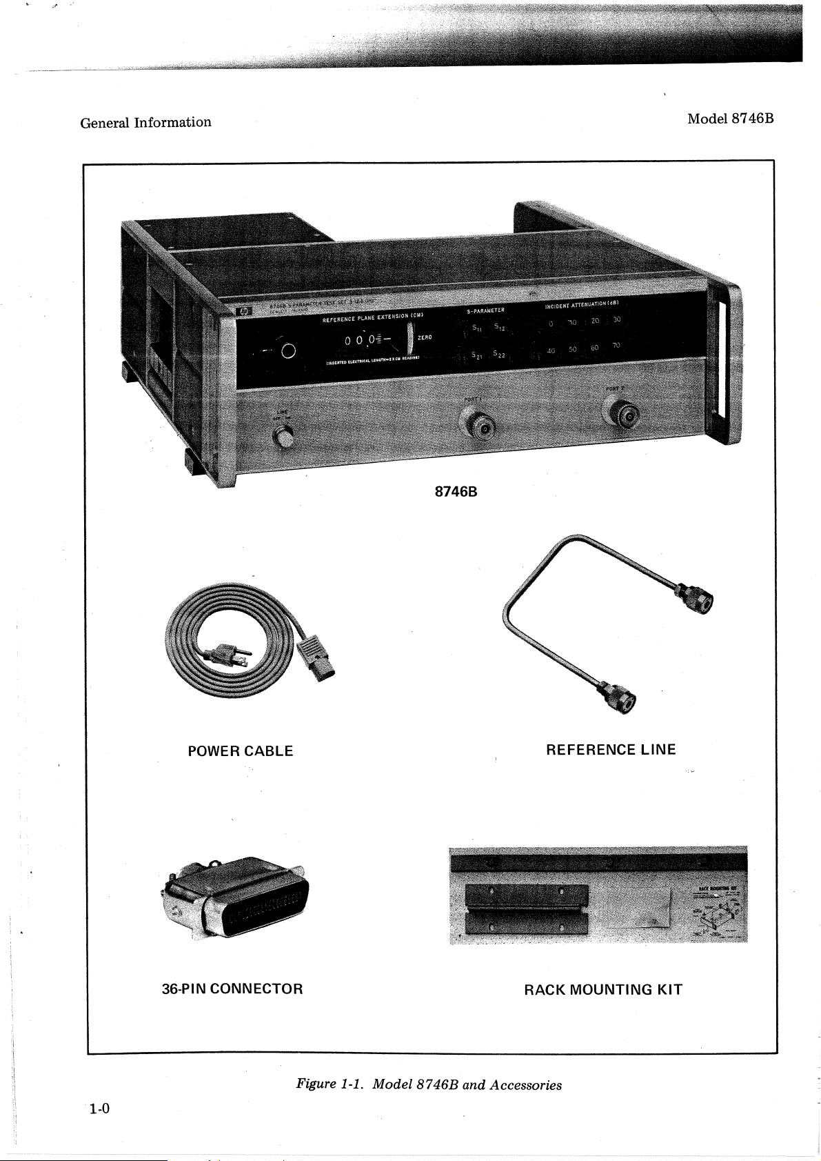
1-1. Model 8746B and Accessories . . . . .
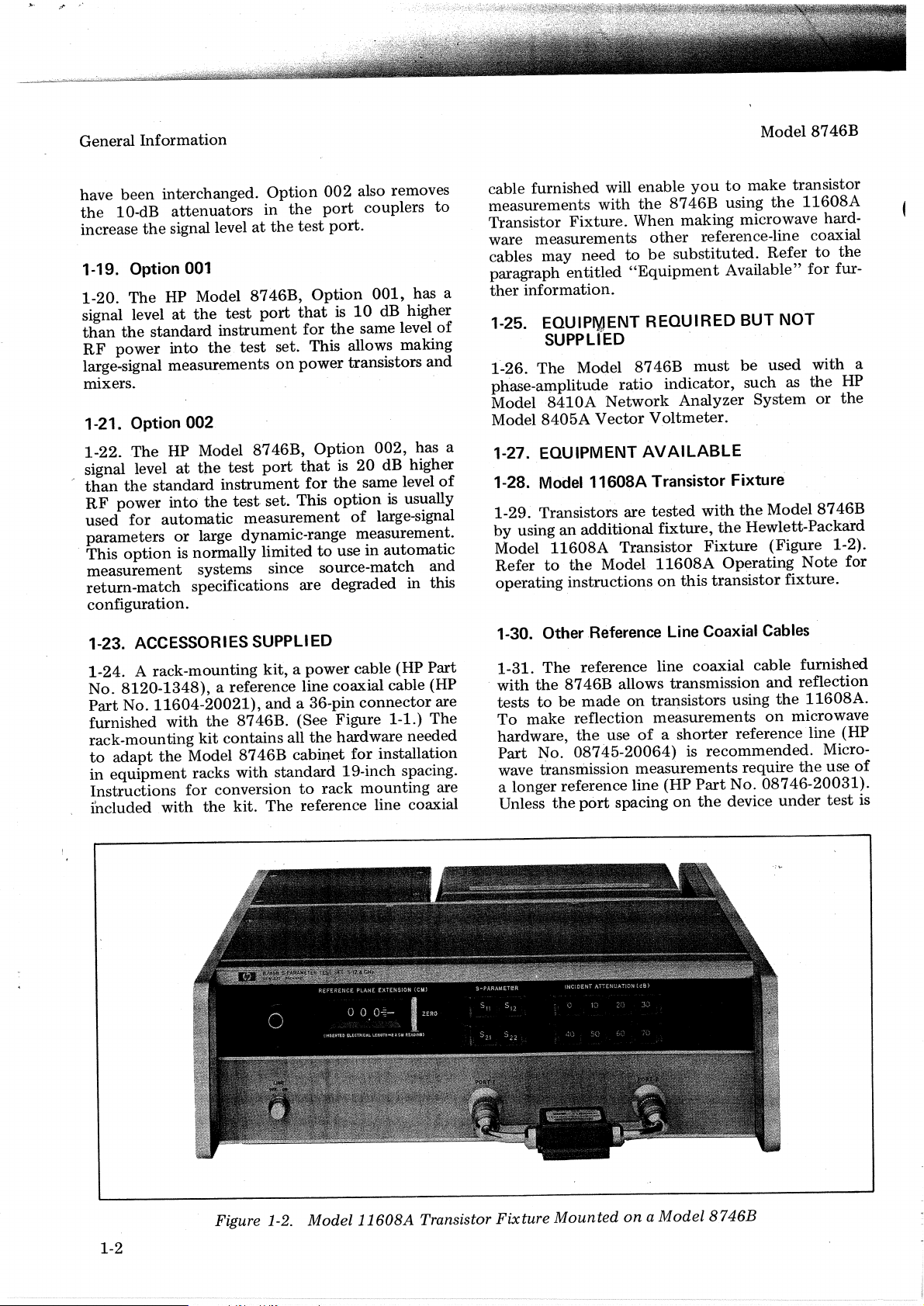
1-2. Model 11608A Transistor Fixture Mounted
on a Model 8746B . . . . . .
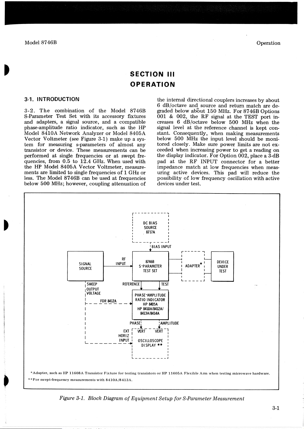
3-1. Block Diagram of Equipment Setup for
S-Parameter Measurement.
3-2. Front Panel Features
,.
Circuits
. .
.'
.
3-3. Rear Panel Features .
3-4. Standard
3-5. Option 001 and 002RFCircuits . . . .
3-6. Reference Line Coaxial Patch Cables .
3-7. Line Switch Bulb Replacement
3-8. Bias Voltage Input. Connections . .
3-9. Transistor Measurement . . . .
3-10. Microwave Hardware Measurement.
3-11.
APC-7
3-12. Pushbutton Selector Bulb Replacement
4-1. Directivity Test Setup . .
4-2. Source Match Test Setup .
4-3. Return Match Test Setup
Digital Counter Friction Clutch Adjustment .
5-1.
Cabinet Parts
6-1.
Front
6-2.
REFERENCE
6-3.
Outboard (W1J1) REFERENCE LINE
6-4.
REFERENCE LINE Coaxial Cable
6-5.
8-1. Troubleshooting Test Setup .
8-~.
Preliminary Troubleshooting. . .
ModelRF
Connectors . . . . . .
Panel Assembly
& TEST Channel Output and
Inboard (W3J1) REFERENCE LINE
Connectors .
Connector.
Connectors (2)
Page
· 1-0
· 1-2
·
3-1
..
3-4
·
3-5
·
3-6
·
3-7
· 3-8
· 3-12
· 3-13
· 3-14
3-16
· 3-18
· 3-19
· 4-2
· 4-4
· 4-6
5-2
6-13
6-14
6-15
6-16
6-17
. 8-13
. . 8-14
Figure
8-3. Reference Channel Troubleshooting
8-4. Test Channel Troubleshooting
8-5. Assembly,
8-6. Assembly, Bottom
8-7. Index Block Diagram
Diagram. . . . . . . . .
8-8.
RF
8-9. RF Circuitry, Top View 8-18
8-10.
RF
8-11. Port 1toPort 2 Coupler Schematic.
8-12. RF Circuit, Schematic . . .
8-13. S-Parameter Troubleshooting. . . . . . . 8-20
8-14.
A4
8-15.A3Driver Assembly, Parts Location
8-16. S-Parameter Latch and Driver Circuits,
Schematic . . . . . . . . . .
8-17. Attenuation Select Troubleshooting
8-18. A4 Switch Panel Assembly Parts Location
8-19.
A2
8-20. Attenuation Latch Circuits . . . . .
8-21. Attenuation Select Troubleshooting
8-22.
A6
8-23.A3Driver Assembly, Parts Location
8-24. Attenuator Driver Circuits. . . .
8-25. Remote Control Troubleshooting . .
8-26. Remote S-Parameter, Block Diagram
8-27. Remote Attenuator, Block Diagram
8-28.A2Buffer Assembly, Parts Location
8-29. Remote Control Circuits . .
8-30. Power Supply Troubleshooting . . . 8-28
8-31. Power Supply Adjustments . . 8-28
8-32.
AlAI
8-33.A2Buffer Assembly, Parts Location . 8-29
8-34. Power Supply,
Top
View . . . . .
View
. . . . .
&Interconnection
Troubleshooting.
CircuitrY, Bottom View . . . . . . . 8-19
Switch Panel Assembly, Parts Location . . 8-20
Buffer Assembly Parts Location
Attenuator Assembly Troubleshooting
Power Supply Assembly, Parts Location . 8-28
Schematic.
..
.....
..
..
. . . . . . . 8-29
Page
· 8-15
· · 8-16
8-.17
· 8-17
8-1
8-18
..
8-19
..
8-19
..
8-21
· . 8-21
· . 8-22
· . 8-22
· 8-23
· . 8-23
· . 8-24
· . 8-24
· 8-25
· . 8-25
· 8-26
· . 8-26
· . 8-26
..
8-27
..
8-27
7
LIST OF TABLES
..
Page
1-4
3-3
3-9
4-8
.
6-1
. 6-3
Table
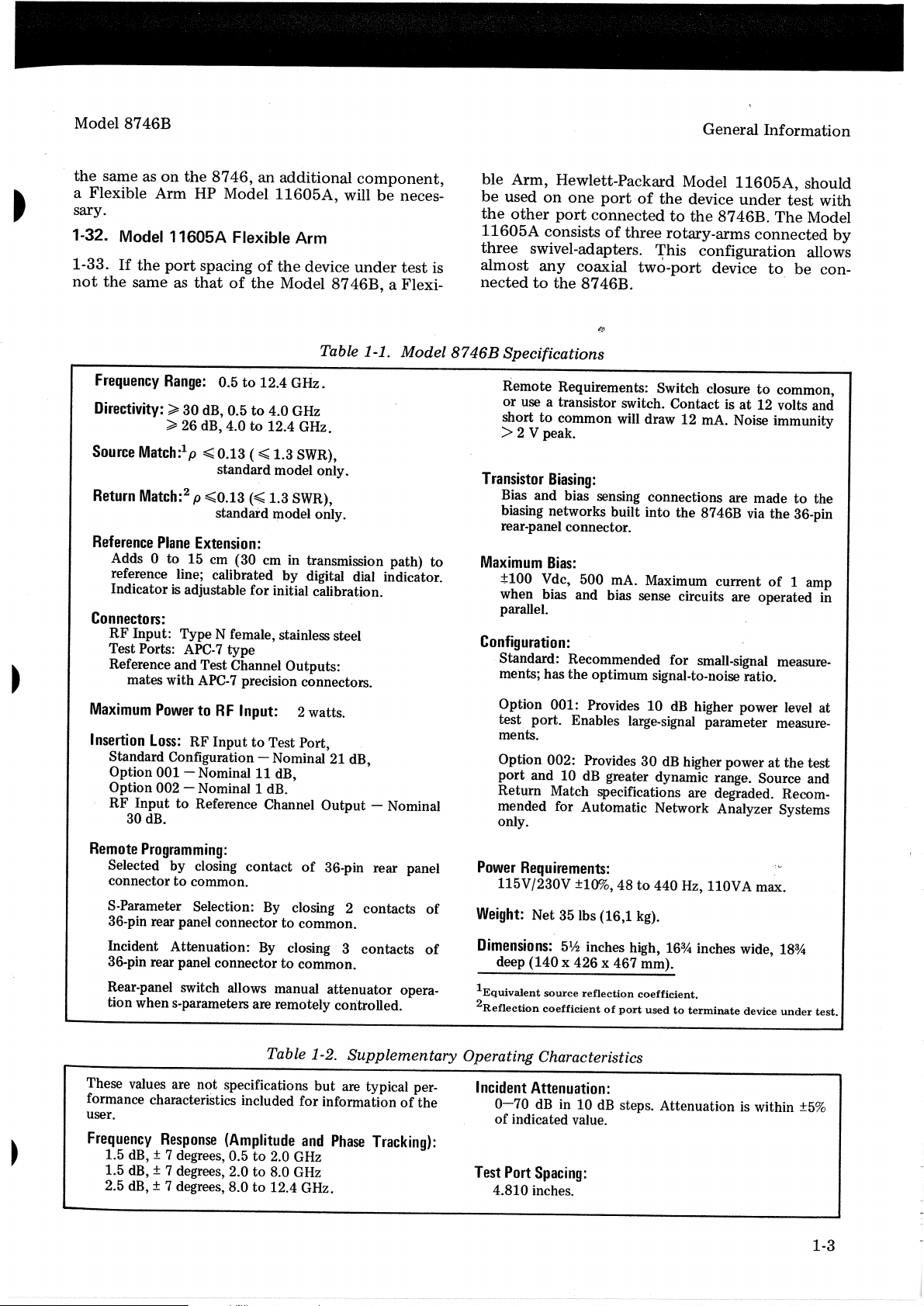
1-1. Model 8746B Specifications . . . . . . . 1-3
1-2. Supplementary Operating Characteristics. . . 1-3
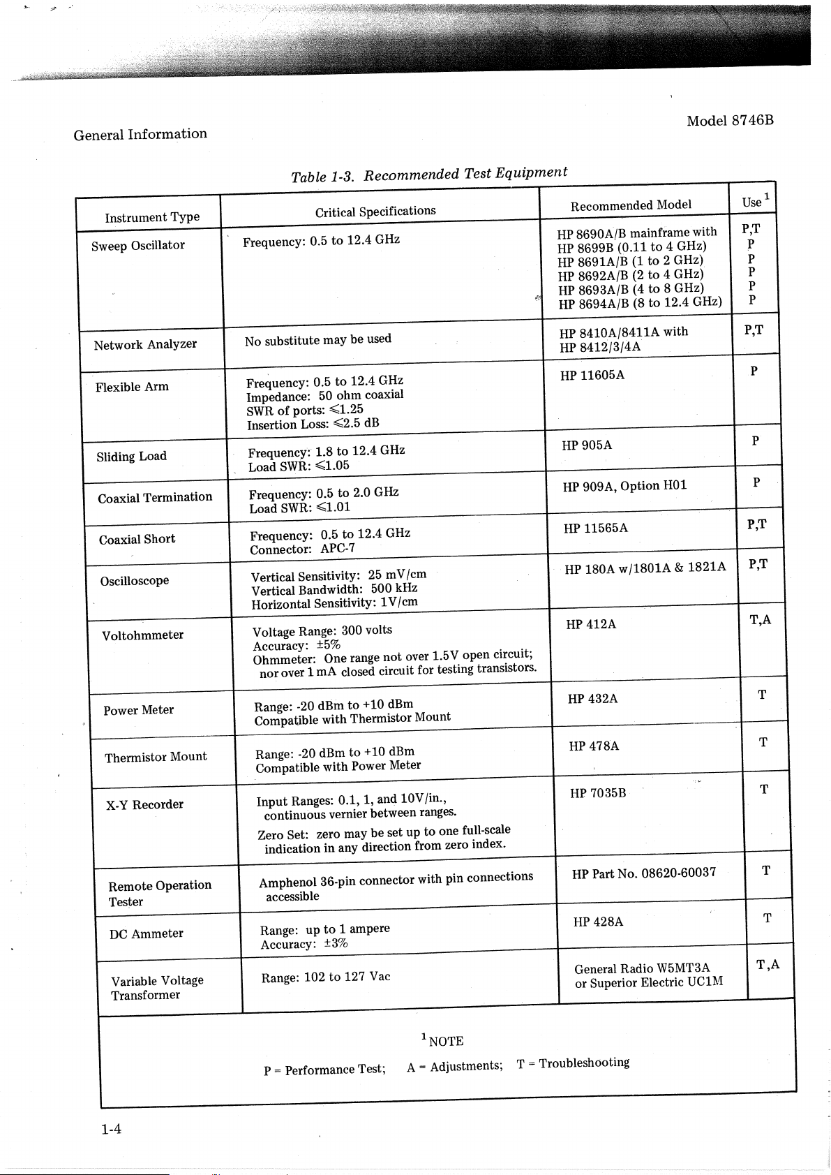
1-3. Recommended Test
3-1. Calibrator Display Indications .
3-2. Remote Input Connector Pin Functions . . .
3-3. Remote S-Parameter Selection Truth Table . . 3-10
3-4. Remote Attenuation Selection Truth Table . . 3-11
4-1. Performance Test Record . . . . . . .
6-1. Reference Designators and Abbreviations
Used in Parts List . . . .
6-2. Replaceable Parts . . . . . . . . .
Equipment..
Table
8-1. Servicing Aids. . . . . . . . . . .
8-2. Schematic Diagram
8-3. Paths Common to Various S-Parameter Paths
8-4. S-Parameter Truth Table . .
8-5. S-Parameter Voltage Table . . . . . .
8-6. Attenuator Truth Table . .
8-7. Attenuation Latch Voltage Table . 8-22
8-8. Attenuator Driver Truth Table . . . . . . 8-24
8-9. Attenuator Driver Voltage Table . . 8-24
8-10. Remote Control Parameter and Attenuation
Select Truth Table . . . . . 8-26
8-11. Remote Control
Notes.
Voltt;ige
. . . . . .
.. ..
Table . . . . . . 8-26
Page
·
8-1
· 8-3
· 8-18
8-20
· 8-20
8-22
iii
Page 7
General Information
Model 8746B
8746B
1-0
POWER CABLE
36-PIN CONNECTOR
Figure 1-1. Model
8746B
REFERENCE LINE
RACK
and Accessories
MOUNTING
KIT
Page 8
Model 8746B
General
Information
I
I
I
I
r
~
I
I
SECTION
GENERAL
1-1. INTRODUCTION
1-2. This manual contains all
to
install,
Hewlett-Packard Model 8746B S-Parameter Test
Set. This section covers
description, options, accessories,
other
is
the
a
reprintofthe
Figure 1-1 shows
supplied
Model
manual is
1-3. INSTRUMENTS COVERED BY
1-4.
The
ries a nine-digit
four
first
last five digits
sequential suffix, uniquetoeach individual instrument.
1-5. This manualisdirectly applicabletoinstruments
listed
Prefix numbers lower
page, refer
for
correcting errors,
of
this
after
yellow Manual Changes
I
the
front
are keyed
number,
and
they
the
manual current
manual as
Hewlett-Packard recommends
request
Complimentary copies
available from all Hewlett-Packard offices.
1-6.
For
prefixes
Changes supplement,
Packard office.
operate,
basic information. Included
Operating Information
with
or
Option
the
TableofSpecifications.
Model 8746B S-Parameter
digits
with
Serial Prefix numbers
on
the
title
to
Section VII.
manualtocover instruments
the
printingofthe
coverofthe
to
both
are revised as
current
the
latest Manual Changes supplement.
information concerning serial
not
listed
test,
first
three
all
of
the
instrument
001
and
one-letter serial
form
the
of
the
page.
than
and
manual.
the
manual's
of
which appear
and
and
on
the
contact
infonnation
adjust
instrument
sectionsofthis manual.
the
or
002.
serial prefix
serial
For
instruments
those
Import~nt
for adaptIng
manual, is provided in a
supple~ent
often
accurate.
of
these supplements are
title pageorin a Manual
and
sp~cifica~ions
WIth
Supplement
equipment
for
Table 1-1 m
number
the
listedonthe
These supplements
print
on
as necessarytokeep
To
accurate as possible,
that
you
the
nearest Hewlett-
required
service
identification,
thIS manual
which
normally
the
st~ndard
MANUAL
Test
Set
number.
number.
form
same as those
with
information
the
contents
manufactured
inserted
date
and
the
title page,
maintain
periodically
number
The
The
Serial
title
under
part
I
INFORMATION
ment
should stay
the
instrument
the
and
is
the
car-
the
the
ordered through
1-9. TABLE OF SPECIFICATIONS
1-10. Complete specifications
1-1. These specifications are
standards
may
be tested. Use these limits
incoming inspectionorat
ance
of
1-11. SUPPLEMENTARY OPERATING
CHARACTERISTleS
1-12. Table 1-2 lists supplementary operating
characteristics. These values are
but
are included
1-13. RECOMMENDED TEST EQUIPMENT
1-14. Table 1-3 lists recommended
for performance testing, troubleshooting,
maintenance.
1-15. DESCRIPTION
1-16. The HP Model 8746B S-Parameter
contains
measuring all four s-parameters
passive two-port device from
Model 8746B is designed primarilytobe
the
Hewlett-Packard Model
ture.
However, measurements
devices
sary coaxial line-lengths in
line.
The
phase-amplitude·
Model
Vector
s-parameter are automatically
pushbuttons
Attenuationofthe
set
with front-panel
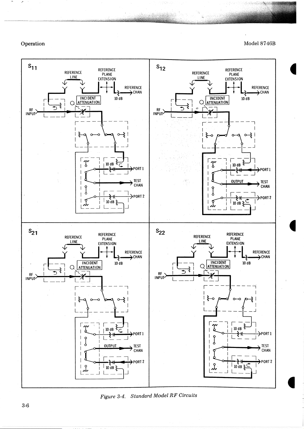
contact-closures. Figure 3-4isa diagramofthe
circuits for
with
the
instrument
pperator.
your
or
limits against which.
the
instrument
for
the
necessary microwave circuits
may
also
be
Model
8410A
Voltmeter. Measuring circuits
8746B
ratio
Network AnalyzerorModel
or
with
the
standard 8746B.
Additional copies
local Hewlett-Packard offIce.
c:rre
the
when
any
time
is in question.
not
the
information.ofthe
of
0.5to12.4
11608A
on
other
made
by
inserting
the
rea:
is used WIth a compatIble
indicator, such as
set
with
remote-contact
incident
RF
signals can also
pushbuttons
for
use
by
ma~
be
listedinTable
performance
the
instrument
testing
the
specifications,
test
equipment
an
GHz.
used WIth
Transistor Fix-
microwave
the
panel
front-panel
or
for
perform-
user.
and
Test
Set
for
active
refere?ce
for
closures.
~he
neces-
the
HP
8405A
each
remote
RF
or
be
1-7. OPERATING INFORMATION
SUPPLEMENT
1-8. Packaged with this basic manualisan Opera-
is
ting Information Supplement which
the
first three sectionsofthis manual. This supple-
a reprint
of
1-17. OPTIONS
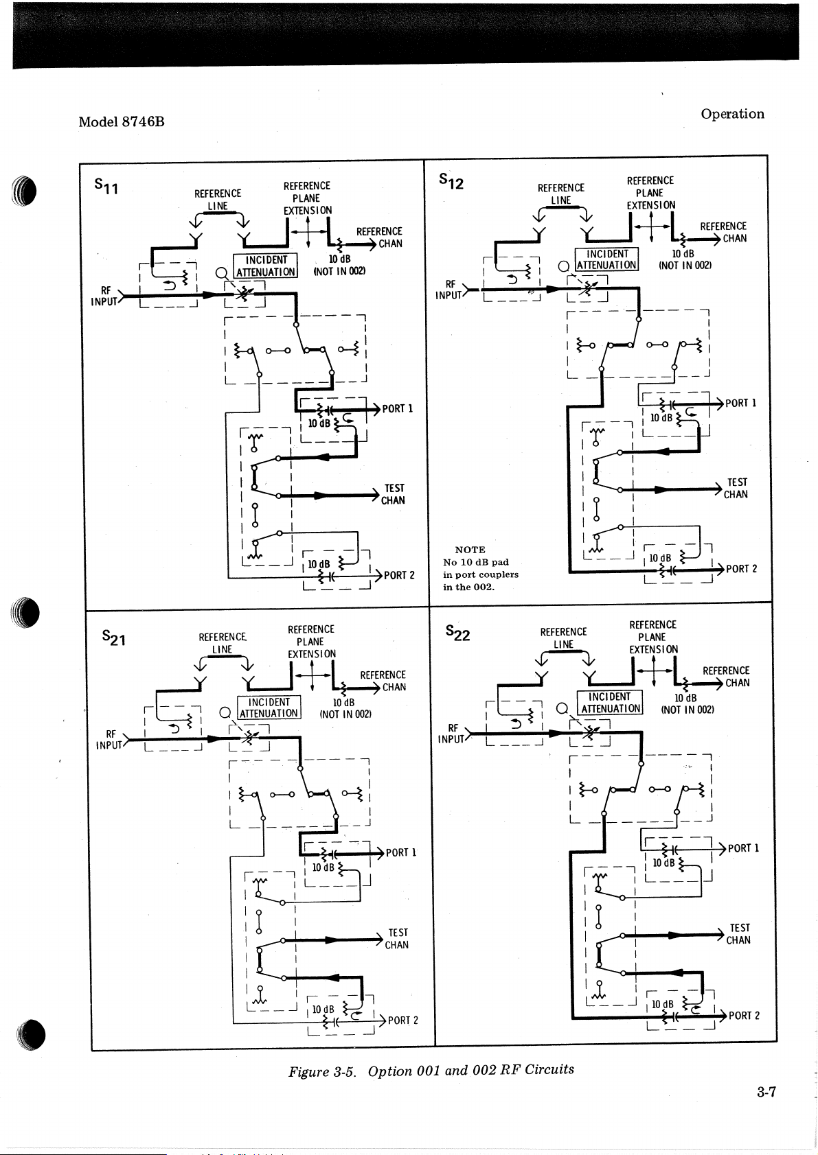
1-18. Figure 3-5isa diagramofthe
Option
in
input
001 and
the
instruments containinganoptionisthat
and
output
Option
002.
The
cables goingtothe
RF
circuits
main difference
switch trees
for
the
1-1
Page 9
General
Information
Model
8746B
have
been
the
10-dB
increase
interchanged.
attenuators
the
signal levelatthe
Option
in
the
002
port
test
1-19. Option 001
1-20.
The
signal level
than
the
standard
RF
power
HP Model
at
the
into
8746B,
test
port
instrument
the.
test
Option
thatis10
for
set..This allows making
large-signal measurementsonpower
mixers.
1-21. Option 002
1-22..The
signal level
than
RF
power
used
parameters
This
measurement
return-match
configuration.
the
standard
for
option
HP Model
at
the
into
the
automatic
or
large dynamic-range measurement.
is normally
8746B,
test
port
instrument
test,
set..This
Option
thatis20
for
measurement
limitedtouseinautomatic
systems since source-match
specifications are degraded
1-23. ACCESSORIES SUPPLIED
also removes
couplers
port.
001,
dB higher
the
same level
transistors
002,
dB higher
the
same level
option
of
large-signal
to
has a
of
and
has a
of
is usually
and
in
this
cable furnished will
measurements
Transistor
ware
cables
paragraph
ther
1-25.
Fixture.
measurements
may
need
entitled
information.
EQUIP~ENT
with
enable
the
youtomake
8746B
using
the
When making microwave hard-
other
to
be
"Equipment
reference-line coaxial
substituted.
Refer
Available"
REQUIRED BUT NOT
SUPPLIED '
1'~26.
The
Model
ph'ase-amplitude
Model
Model
8410ANetwork
8405A
1-27. EQUIPMENT
ratio
Vector
87
46Bmust
indicator,
Analyzer
Voltmeter.
AVAILABLE
be
such
System
used
as
1-28. Model 11608A Transistor Fixture
1-29.
Transistors are
by
usinganadditional
Model
Refer
operating
11608A
to
the
instructionsonthis
Model
tested
fixture,
Transistor
11608A
with
the
the
Hewlett-Packard
Fixture
Operating
transistor
Model
(Figure 1-2).
fixture.
1-30. Other .Reference Line Coaxial Cables
transistor
11608A
to
the
for
fur-
with
the
HP
or
the
8746B
Note
for
a
1-24. A rack-mounting
No.
8120-1348),
Part
No.
11604-20021),
furnished
with
rack-mounting
to
adapt
the
in
equipment
Instructions
included
with
a reference line coaxial cable (HP
the
8746B.
kit
contains
Model
racks
for
8746B
with
conversiontorack
the
kit.
kit,apower
and
a 36-pin
cable (HP
connector
(See Figure 1-1.)
all
the
hardware needed
cabil1et
standard
for
19-inch spacing.
mounting
The
reference line coaxial
Part
are
The
installation
are
1-31.
The
reference line coaxial cable furnished
with
the
8746B
teststobe
To
make
hardware,
Part
No.
wave transmission
allows transmission
madeontrap.sistors using
reflection
the
measurements
useofa
shorter
08745-20064)isrecommended.
measurements
a longer reference line (HP
Unless
the
port
spacingonthe
and
the
on
reference line (HP
require
Part
No.
08746-20031).
device
reflection
11608A.
microwave
Micro-
the
use
under
test
of
is
1-2
Figure
1-2. Model
11608A
Transistor
Fixture
Mountedona
Model
8746B
Page 10
Model
the
a Flexible Arm HP Model
8746B
same asonthe
8746,anadditional
11605A,
sary.
1-32. Model 11605A Flexible
1-33.Ifthe
not
the
port
same as
spacingofthe
thatofthe
Arm
device
Model
component,
willbeneces-
under
test
8746B,
a Flexi-
General
ble
Arm,
Hewlett-Packard Model
be
usedonone
the
other
11605A
three
is
almost
consistsofthree
swivel-adapters.
any
nectedtothe
port
port
connectedtothe
coaxial
8746B.
t.J!o.
·of
the
rotary-arms
'rhis
two-port
device
configuration
device to.
11605A,
under
8746B.
connected
Information
should
test
with
The
Model
by
allows
be
con-
Table 1-1. Model
Frequency
Directivity:
Source
Return
Reference
Adds 0 to 15 cm (30 cm in transmission path)
reference line; calibrated by digital dial indicator.
Indicator
Range:
~
~
Match:
Match:
Plane
0.5to12.4 GHz.
30 dB, 0.5to4.0 GHz
26 dB, 4.0to12.4 GHz.
1
p
~
0.13 (~1.3 SWR),
standard model only
2
p
~0.13
standard model only.
Extension:
is
adjustable for initial calibration.
(~
1.3 SWR),
..
Connectors:
RF Input: Type N female, stainless steel
Test Ports:
Reference and Test Channel Outputs:
mates with
Maximum
Insertion
Standard Configuration - Nominal 21 dB,
Option
Option 002 - Nominal 1 dB.
RF Input
30 dB.
APC-7
type
APC-7
precision connectors.
PowertoRF
Loss:
RF InputtoTest Port,
001-
to
Input: 2 watts.
Nominal 11 dB,
Reference Channel Output - Nominal
to
8746B
Transistor
Maximum
Configuration:
Specifications
to
Remote Requirements: Switch closure
or use a transistor switch. Contactisat
shorttocommon will draw 12 rnA. Noise immunity
common,
12 volts and
>2 V peak.
Biasing:
Bias and bias sensing connections are madetothe
biasing networks built into the 8746B via the 36-pin
rear-panel connector.
Bias:
±100 Vdc, 500 rnA. Maximum currentof1 amp
when bias and bias sense circuits are operated in
parallel.
Standard: Recommended for small-signal measurements; has the optimum signal-to-noise ratio.
Option 001: Provides
test port. Enables large-signal parameter measurements.
Option 002: Provides 30dBhigher power at the test
port and 10
Return Match specifications are degraded. Recommended for Automatic Network Analyzer Systems
only.
dB
10dBhigher power level at
greater dynamic range. Source and
Remote
Programming:
Selected by closing contact
connectortocommon.
S-Parameter Selection:
36-pin rear panel connectortocommon.
Incident Attenuation:
36-pin rear panel connectortocommon.
Rear-panel switch allows manual attenuator opera-
tion when s-parameters are remotely controlled.
of
36-pin rear panel
By
closing 2 contacts
By
closing 3 contacts
of
of
Table 1-2. Supplementary Operating Characteristics
These values are not specifications but are typical performance characteristics included for informationofthe
user.
Frequency
1.5
1.5
2.5
Response
dB,
± 7 degrees, 0.5
dB,
± 7 degrees, 2.0to8.0
dB,
± 7 degrees, 8.0to12.4 GHz.
(Amplitude
to
2.0
and
GHz
GHz
Phase
Tracking):
Power
Requirements:
115V/230V ±10%,48to
Weight:
Dimensions:
lEquivalent
2Reflection
Incident
Test
Net 35 lbs (16,1 kg).
5th inches high,
deep (140 x 426 x 467 mm).
source
reflection
coefficientofport
Attenuation:
0-70
dB
of
indicated value.
Port
4.810 inches.
in 10dBsteps. Attenuationiswithin
Spacing:
440 Hz, 110VA max.
163~
inches wide,
coefficient.
usedtoterminate
device
183~
under
test.
±5%
1-3
Page 11
General
Information
Instrument Type
Sweep Oscillator
Table
Frequency: 0.5
Rec.ommended Test Equipment
1-3.
Critical Specifications
12.4 GHz
to
Recommended Model
8690A/B mainframe with
HP
8699B (0.11
HP
8691A/B
HP
8692A/B (2
HP
8693A/B (4
HP
t"0
8694A/B (8
HP
4 GHz)
to
2 GHz)
to
(1
4 GHz) P
to
8 GHz)
to
12.4 GHz) P
to
Model
8746B
Use
P,T
;P
P
P
1
Network Analyzer
Flexible Arm
Sliding Load
Coaxial Termination
Coaxial Short
Oscilloscope
Voltohmmeter
Power Meter
No substitute may be used
12.4 GHz
Frequency: 0.5
to
Impedance: 50 ohm coaxial
SWR
Insertion Loss:
Frequency:" 1.8
~1.05
SWR:
Load
Frequency: 0.5
~1.01
SWR:
Load
Frequency: 0.5
~2.5
12.4 GHz
to
2.0 G
to
12.4 GHz
to
dB
Hz
~1.25
ports:
of
Connector: APC·7
Vertical Sensitivity: 25 mV/crn
Vertical Bandwidth: 500 kHz
Horizontal Sensitivity: 1V/cm
Voltage Range: 300 volts
Accuracy:
±5%
Ohmmeter: One range not over 1.5V open circuit;
norover 1 rnA closed circuit for testing transistors.
+10 dBm
Range: ·20 dBm
to
Compatible with Thermistor Mount
8410A/8411A with
HP
8412/3/4A
HP
11605A
HP
905A
HP
909A, Option
HP
11565A
HP
/1801A
w
l80A
HP
412A
HP
432A
HP
HOI
&
1821A
P,T
P
P
P
P,T
P,T
T,A
T
Thermistor Mount
Recorder
x·y
Remote Operation
Tester
Ammeter
DC
Variable Voltage
Transformer
1-4
+10 dBm
Range: ·20 dBm
to
Compatible with Power Meter
Input Ranges: 0.1, 1, an4 10V/in.,
continuous vernier between ranges.
Zero Set: zero may be set up to one full·scale
indication inany direction from zero index.
Amphenol 36·pin connector with pin connections
accessible
1 ampere
Range: up
Accuracy:
Range: 102
=
P
to
±3%
Vac
127
to
Performance Test; A
NOTE
1
Adjustments;
=
T
478A
HP
7035B
HP
Part No. 08620·60037
HP
428A
HP
General Radio W5MT3A
or Superior Electric
Troubleshooting
=
v
.:
UC1!\1
T
T
T
T
T,A
Page 12
Model
8746B
Installation
2-1.
INITIAL
INSPECTION
2-2. Mechanical Check
2-3.Ifdamagetothe
ask
that
the
carrier's
instrumentisinpacked.
mechanical
material
damage.
for
signsofsevere stress.
shipping
agent
Inspect
Also,
2-4. Electrical Checks
2-5.
The
should
suitable
IV,
.
performance
be
Perf.ormance
electrical
verified
for
incoming
testislistedinTable
performance
on
receipt.Aperformance
inspection
Test.
Equipment
2-6. Claims for Damage
2-7.Ifthe
in
transit,
Hewlett-Packard
shipping
rier's
replacement
waiting
2-8.
sp,ected
defects.Ifthereisany
cal
performanceisnot
your
Model
carton
inspection.
for
claims
Before
and
Hewlett-Packard
8746Bismechanically
notify
office
and
The
or
repairofyour
settlement
shipment,
found
freeofelectrical
the
carrier
immediately.
packing
HP
office
this
deficiency,orif
within
office.
2-9. PREPARATION FOR'USE
2-10. Power Requirements
cartonisevident,
be
present
the
instrument
check
against
the
cushioning
of
Model
is giveninSection
required
1-3.
and
the
Retain
material
instrument
instrument
specification,
will
the
and
for
arrange
carrier.
mechanical
the
SECTION
II
INSTALLATION
d.
e.
the
switch
tion.
when
8746B
test
for
damaged
nearest
the
car-
without
was in-
electri-
notify
the
for
the
the
for
and'the
f.
g. Slide
h.
2-14. THREE-CONDUCTOR
2-15.
Electrical
ommends
grounded.
equipped
when
grounds
3-prong
wire.
2-16.
operating
put,
the
pigtailonthe
2-17. OPERATING ENVIRONMENT
2-18.
Model
but
from0to
humidity
Remove
With
a~f.screwdriver
arm
with
The
right-hand
left-hand
Replace
clear
Replace
To
protect
Manufacturers
that
the
All
Hewlett-Packard
witha3-conductor
plugged
the
connectorofthe
To
use a
The
8746Bisroom
it
will
up
into
instrument.
preserve
the
instrument
3-prongto2-prong
normal
operate
+55
degreesC.It
to
95%.
fuse.
or
pointed
the
arrowto115or230
positionisfor
positionisfor
fuse
withafuseofcorrect
plastic
power
cable.
230
covertoright.
POWER
operating
instrument
the
adaptertoground.
operating
personnel,
Association
panel
power
an
appropriate
The
offset
power
protection
temperature
to
its
cableisthe
froma2-connector
adapter
environment
specified
will
tool,
115
volt
volt
input~
CABLE
the
National
(NEMA)
and
cabinet
instruments
cable
receptacle,
pin
on
ground
feature
and
connect
for
(25.:elegrees
performance
operate
move
posi-
input
value.
rec-
be
are
which,
the
when
out-
the
C),
in
any
2-11.
The
115or230
power.
2-12.
2-13.
combination
holder,
input
Power
115/230
This
and
voltage
a.
Remove
b.
Slide clear plastic
c. Pull
Model
8746B
Vac ±10%,48to
consumption
Volt
Operation
instrument
input-voltage
circuit
outonhandle
has a
of
power-cable
proceed
power
requiresapower
400
Hz,
is less
than
power
switch.
cable.
coverofmoduletoleft.
marked
module
receptacle,
as follows:
source
single-phase
110
To
change
"FUSE
VA.
that
is a
fuse
the
PULL".
of
2-19.
The
bench
make
when
instrument
operation.
full-width
stacked.
cabinet
The
plastic
modular
has
feet
instruments
2-20. STORAGE AND SHIPMENT
2-21. Packaging
2-22. Original-Type Packaging.
packing
factory
Packard
line,
ping
servicing
materials
are
available
office.
wrapitseparately,
container.Ifthe
and
Remove
repair,
identical
through
attachatag
to
those
your
the
rear-panel
and
includeitin
8746Bisbeing
indicating
plastic
are
Containers
nearest
feet
shaped
self-aligned
used
Hewlett-
reference
the
returned
by
type
for
to
and
the
ship-
for
of
'2-1
Page 13
Installation
Model
8746B
service
ment
required,
serial
"FRAGILE"
respondence
instrument
the
number.
serial
return
full
number.
assure careful handling.
to
regarding
its full HP
by
address,
A.lso
your
2-23. Other Packing Materials.
instructions
eral
commercially available materials:
with
Remove
a.
separately,
it
wrap
container.
plastic.
office
service
full serial
and
Wrap
(If
center,
or
required,
should
the
the
shipping
attach
return
number.)
be
rear-panel reference line,
include
and
instrument
a Hewlett-Packard service
to
tag
a
address,
and
mark
instrument,
model
following gen-
The
for
used
in
it
heavy
in
indicating
model
full instru-
box
the
cor-
any
In
refer
number
and
repackaging
shipping
the
paper
type
the
number,
to
or
of
b. Use a
carton
wall
adequate.
c. Use
4 inch layer)
to
provide
to
inside
the
cardboard.
d.
e.
assure
to
strong
made
enough
shipping
of
shock-absorbing
around
cushion
firm
container.
Protect
Seal the·shipping
shipping
the
Mark
careful
handling.
container.
lb.
350
all sides
and
the
container
container
test
the
of
prevent
control
securely.
A double-
material
material
instrument
movement
with
panel
"FRAGILE"
is
(3
2-2
Page 14
Model
8746B
Operation
3-1. INTRODUCTION
The
3-2".
S-Parameter Test
and
adapters, a signal source,
phase-amplitude
Model
Vector
tem
for
transistor
performed
.quencies, from
the
HP
ments
less.
The
below
combination
Set
ratio
8410A
Network
Voltmeter· (see Figure 3-1)
measuring s-parameters
or
device. These
at
single frequencies
0.5
to
Model
are
500
8405A
limitedtosingle frequenciesof1 GHz
Model
8746B
MHz; however, coupling
SECTION
OPERATION
of
the
Model 8746B.
with
its accessory fixtures
andacompatible
indicator,
AnalyzerorModel
12.4
Vector
canbeusedatfrequencies
SIGNAL
SOURCE
I
SW.EEP
OUTPUT
:
VOLTAGE
I
~--------
I
I
I
:
I
I INPUT:
L - - - - - - - -
such
as
m~ke
of
almost
measurements
or
at
swept
GHz.
When used
Voltmeter,
attenuation
INPUT
FOR
8412A
HORIZ
the
8405A
up
a sys-
can
with
measure-
r----------~
I I
I
I I
:
I
I I
I I
L----r----J
RF
...
REFERENCE
PHASE-AMPLI
RATIO
..
PrH~~~
EXT
I I
~
I I
I I
I I
L J
the
6
graded
001
creases 6
HP
sign3J.
stant.
below
any
be
fre-
tored
ceeded
the
pad
impedance
or
uring active devices. This
possibilityoflow
DC
BIAS
SOURCE
8111A
.BIAS
8146B
TEST
SET
devices
of
S-PARAMffiR
1 1
TUDE
INDICATOR
HP
8405A
HP
8410A/8412AI
8413A/8414A
~~M!l·11TUDE
VERT
OSCILLOSCOPE
01
SPLAY
VERT
** :
III
internal
dB/octave
&
display
at
I
f
I
INPUT
~
------i
TEST
I
I
directional
and
below
002,
at>6ut
the
dB/octave
level
at
Consequently,
500
MHz
closely. Make sure
when
increasing
indicator.
the
RF
matchatlow
under
test.
r-----
I I
I * I
I
ADAPTER
I I
I I
L J
source
RF
the
reference
the
INPUT
frequency
-,
L-
I
r--
couplers
and
150
MHz.
signalatthe
below
when
input
making
level
power
powertoget
For
Option
connector
frequencies
pad
oscillation
DEVICE
UNDER
TEST
increasesbyabout
return
500
For
match
8746B
TEST
MHz
Options
port
when
channeliskept
measurements
should
limits are
be
not
a reading
002,
place a 3-dB
forabetter
when
will
reduce
with
are de-
in-
the
con-
moni-
ex-
on
meas-
the
active
*
Adapter,
**For
suchasHP
swept-frequency
Figure 3-1.
11608A
Transistor
measurements
with
Block
Fixture
for
testing
transistorsorHP
8410Aj8413A.
DiagramofEquipment
Setup
11605A
Flexible
Ann
when
testing
for S-Parameter Measurement
microwave
hardware.
3-1
Page 15
Operation .
Model 8746B
3-3. PANEL FEATURES
3-4.
Front
and
indicators are described in Figures 3-2
In
these figures
keyed
to
and
rear
panel controls, connectors,
the
numbersonthe
the
description numbers.
3-5. OPERATING PRECAUTIONS
3-6.
Maximum
3-7. Powerinexcessof2
INPUT
under
the
power
3-8.
jack
test
instrument.
limitofthe
RF
PowertoTest Device
or
into
RF Power
returned
PORT'l
Also,
associated
watts,
from
or
PORT2may
do
not
network
CAUTION
Do
NOT use excessive
the
device
cause
collector
power,
under
the
transistor
current
investigate
RF
test.
Too
to
oscillate.
varies
the
possibilityofoscil-
lation.
On
3-9.
device
internal
channel
all models
under
step-attenuator
output.
test
When
of
may
the
the
8746B,
be
decreased using
without
standard
step-attenuatorissettozero,
under
level and
mately
attenuatorissettozero,
te~t
, level.
to
same levelasthe
and
,
at
s-parameter configurations are
The
test
is approximately 21
poweratthe
31
is approximately
For
zero,
powertothe
002,
with
constant,
powertothe
dB
down.
Option
the
reference channel is approxi-
For
11
002,
RF
input.
poweratthe
approximately 6 dB/octave
circuits
for
the
same circuits
standard
for
Option
powertothe
dB below
when
device
For
device
model
showninFigure 3-4.
Options
shown in Figure 3-5.
3-10. MaximUITI DConRF Lines
3-11. DC voltages
transmission lines in
exceed ±
100
volts as
on
the
inner
the
Model
the
insulationofthe
capacitors may break down. Do
than
0.5
amponeither BiasorBias Sense leads.
and
illustration are
either
into
the
an active device
damage
exceed
the
analyzer.
input
much
with
power
RF
RF
may
If
input
to
the
powertothe
reducing reference
8746B
powertothe
dB
below
001,
internal
device
RF
when
device
the
RF
the
attenuatorisset
under
under
below
testisat
both
Options 001
reference
test
500
8746B
001
and
port
increases
MHz.
in all
002
conductorofthe
8746B
must
internal
not
draw
3-3.
RF
input
the
input
the
under
input
the
held
RF
are
not
more
if
the
properly
tion
trace are less
pushbuttons
not
calibrate properly, refer
amplitude variations in
function normally.Ifthe8746B will
than
2.5dBl
to
the
calibra-
and
the
8746B
Section VIII, Ser-
vice.
3-14. OPERATING INSTRUCTIONS
General Measurement Description
3-15.
3-16. The Model
be
.usedtomake
binations
of
fied block diagram
Figure 3-1.
tude
ratio indicator, suchasthe
HP
8410A/8411A
external oscilloscope,
tions
for
using
Figures 3-9
modified for use
the
Operating
and adapting
operation
tested
sistor
transistor
nents also
the
at
by
connecting
Fixture
under
maybetestedinthe
physical limits
exceeded. Consult
office. Microwave hardware
the
S-Parameter Test
Model
3-17.
11605A
The
following general
steps necessary when making measurements
8746B
measurements
S-Parameter
with
Test
Set
several com-
complementary equipment. A simpli-
ofatest
The'
display indicator is a .phase-magni-
with
or
the
8410A
and
3-10. These instructions
with
the
and
Service Manual
the
instructions for single-frequency
setupisshown
HP
8405Aorthe
8412A,
8414A
8413A
plug-in. Instruc-
system are given
8405A
by
for
with
can
referring
the
8405A
lower frequencies. Transistors are
the
HP Model
to
the
8746B
testinthe
of
the
nearest Hewlett-Packard
Setbyaccessories,
11608A.
the
may
~1608A
and.
inserting
Other
11608A,
11608A
be
connected
Tran-
compo-
providing
are
suchasthe
Flexible Arm. .
outline
explains
may
in
an
in
be
to
the
not
to
the
with
any combinationofequipment. These instructions
the
same
for
both
the
are
and 002 models
a.
If
swept-frequency phase measurements
are
to
be made,
line-lengths
must
of
the
the
be
standard and
8746B.
reference and
equaL
The
reference channel is adjusted
REFERENCE PLANE EXTENSION
length
cable
can
of
the
on
the
be
removed and
REFERENCE LINE coaxial
rear paneL The REFERENCE LINE
other
length reference lines
(see Figure 3-6) can be installed
equalize
To best utilize
SION range, install
ENCE LINE coaxial
the
test
and reference channel line lengths.
the
REFERENCE PLANE EXTEN-
oneofthe
patch
following
cables:
Option
I
test
channel
length
by
varying
and
to
approximately
REFER-
of
patch
001
the
the
the
TRANSISTOR FIXTURE (11608A): Use HP Part
No. 11604-20021 included with 8746B.
3-12. OPERATOR'S CHECK
3-13.
To
check
calibrate
the
the
calibration trace. The
the
system
8746B
for
a measurement. Observe
3-2
operation,
8746B
set
is
operating
up
to
INotchesof1dBat
causedbyresonancesofRF
approximately
700
chokesinthe
MHz
bias
are
input
normal.
leads.
They
are
Page 16
Model
8746B
Operation
MICROWAVE HARDWARE:
Reflection:
Transmission
nated
in
Use HP
with
an
HP
Part
No.
Device
11605A:
08745-20064.
Under
Test
Use HP
08746-20031.
Note
When using
the
measurement
mismatch.
tor
(see Figure3-10)toreduce
the
Use a
11605A
the
accuracy
maybedegraded
10
dB isolating
mismatch.
CALIBRATION
b.
Calibrate
.
urement
or
wave
short
by
through-line calibrator. When measuring micro-
hardware,
connected
measurements
ofa11605A
ing
for
transmission measurements.
1..
Balance
ence
REFERENCE
obtain
quency
.
the
system
terminat~ng
calibrate
to
the
or
a through-line
connected
the
electrical
and
test
for
the
11608A
the
8746B
test
between
channels
PLANE
the
least phase change
indication
on
s-parameter
with
port
for
calibrator
the
lengthofthe
by
adjusting
EXTENSION
the
display indica-
tor.!
2.
Adjust
tor
to
Table
for
the
3-1.
the
controls
a display
calibrator
on
the
display indica-
indication
corresponding
being used as shown
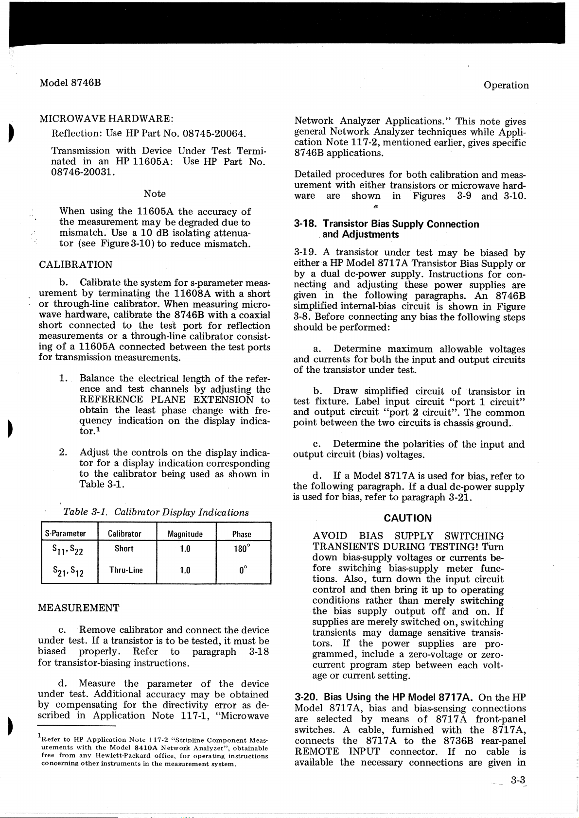
Table 3-1. Calibrator Display Indications
S-Para
meter
S11,S22
S21,S12
Calibrator
Short
Thru-line
Magnitude
.
1.0
1.0
MEASUREMENT
c.
Remove
under
biased
for
under
by
scribed
1RefertoHP
test.Ifa
properly.
transistor-biasing instructions.
d.
Measure
test.
compensating
in
from
Application
with
any
other
urements
free
concerning
calibrator
and
connect
transistoristobetested,itmust
Refer
the
Additional
for
Application
the
Hewlett-Packard
Note
Model
8410A
instrumentsinthe
to
parameter
accuracy
the
directivity
Note
117-2
"Stri.pline
Network
office,
measurement
paragraph 3-18
of
may
117-1,
Component
Analyzer",
for
operating
Termi-
Part
No.
of
due
to
attenua-
meas-
withashort
a coaxial
reflection
consist-
test
ports
refer-
the
with
fre-
Phase
0
180
0
0
the
device
the
device
be
obtained
error
as de-
"Microwave
Meas-
obtainable
instructions
system.
to
in
be
Network
general
cation
8746B
Detailed
urement
ware are
3-18. Transistor
3-19. A
either
byadual
necting
given
simplified internal-bias
3-8. Before
should
and
of
the
test
and
point
output
the
is
used
Analyzer
Network
Note
117-2,
Applications."
Analyzer
mentioned
applications.
procedures
with
and
Adjustments
.
transistor
a HP
and
in
the
shown
Model
dc-power
adjusting
for
both
either
transistorsormicrowave
in
Figures 3-9
Bias
Supply
under
871
test
7A Transistor Bias
supply.
these
following paragraphs.
circuitisshowninFigure
be
performed:
a.
Determine
currents
transistor
b.
Draw
fixture.
output
between
c.
Determine
circuit
d.
If
connecting
for
both
under
simplified
Label
circuit
the
(bias) voltages.
a Model
any
maximum
the
input
test.
circuit
input
circuit
"port2circuit".
two
circuits is chassis
the
polaritiesofthe
8717
A is used
following paragraph.Ifa
for
bias,
refertoparagraph
This
techniques
earlier, gives specific
calibration
Connection
may
Instructions
power
bias
the
following steps
allowable voltages
and
of
"port1circuit"
for
dual
dc-power
3-21.
CAUTION
AVOID BIAS SUPPLY SWITCHING
TRANSIENTS
down
fore
tions.
control
bias-supply voltagesorcurrents
switching bias-supply
Also,
and
conditions
the
bias
supplies are merely
transients
tors.
If
grammed,
current
age
3-20.
Model
program
or
current
Bias
Using theHPModel 8717
871
7A, bias
are selected
switches. A cable, furnished
connects
the
REMOTE INPUT
available
the
DURING
TESTING!
meter
turn
then
rather
supply
may
the
down
bringituptooperating
output
damage sensitive transis-
power
the
than
merely
switched
supplies
off
input
and
on,
include a zero-voltageorzero-
step
between
setting.
and
bias-sensing
by
means
of
8717Afront-panel
with
8717Ato
connector.
necessary
the
8736B
If
connections
note
while Appli-
and
and
be
biased
Supply
for
supplies are
An
8746B
output
circuits
transistor
The
common
ground
input
bias,
refer
supply
Turn
be-
func-
circuit
switching-
on.
switching
are
pro-
each volt-
A.
On
the
connections
the
871
rear-panel
no
cable is
are given
gives
meas-
hard-
3-10.
by
or
con-
in
.
and
to
If
HP
7A,
in
3~3
Page 17
Operation
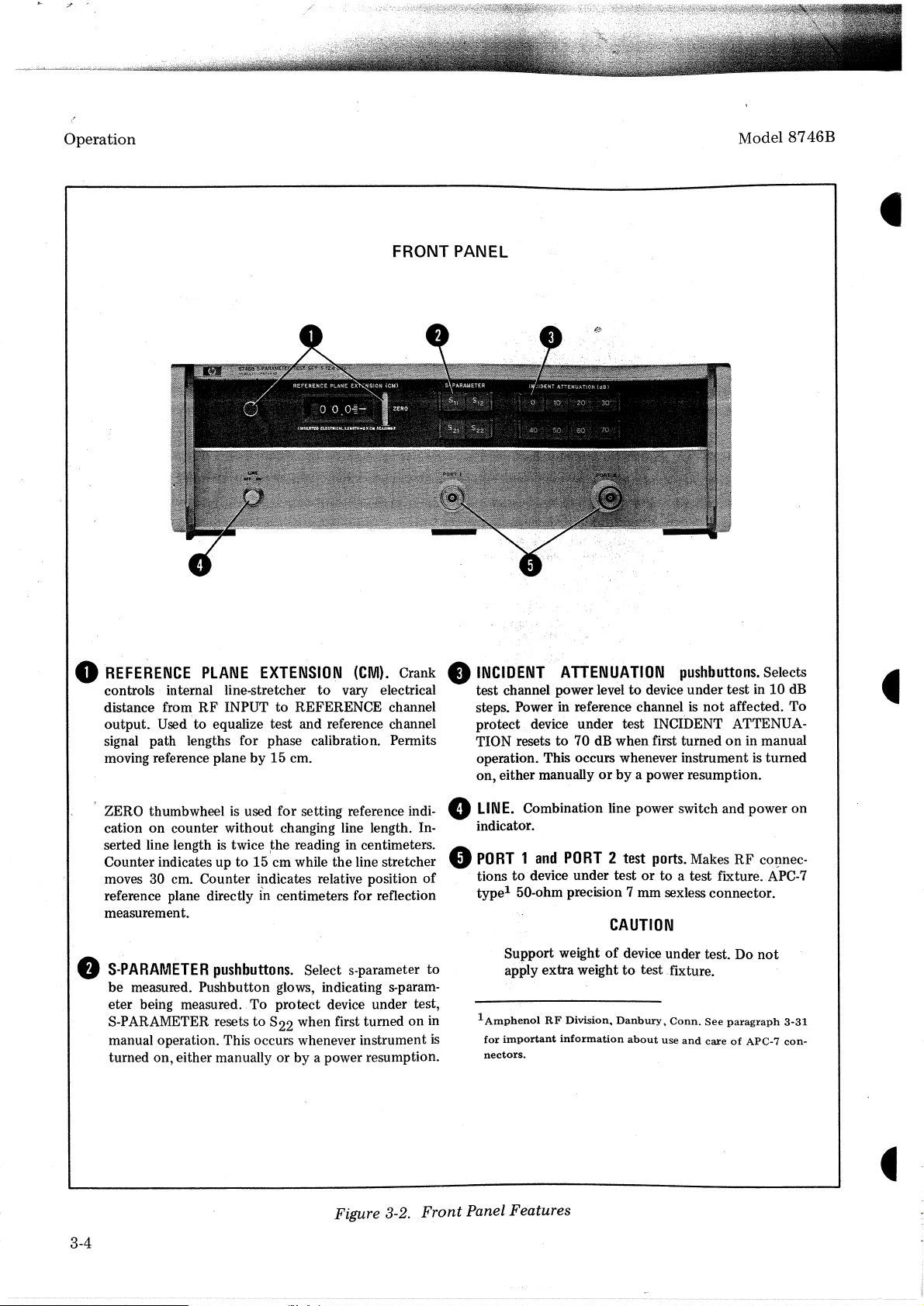
FRONT PANEL
Model
8746B
o
REFERENCE
controls internal line-stretcher
distance from
output. Used to equalize test and reference channel
signal path lengths for phase calibration. Permits
moving reference plane
ZERO thumbwheel
on
cation
serted line length
Counter indicates up
moves 30 cm. Counter
reference plane directlyincentimeters for reflection
measurement.
•
S-PARAMETER
be
measured. Pushbutton glows, indicating s-parameter being measured. To protect device under test,
S-PARAMETER resets to 822 when first turned on
manual operation. This occurs whenever instrument
turned on, either manually or by a power resumption.
PLANE
RF
counter without changing line length. In-
pushbuttons.
EXTENSION
INPUTtoREFERENCE channel
by
15 cm.
is
used for setting reference indi-
is
twice
~he
reading in centimeters.
to
15 cm while the line stretcher
i~dicates
Select s-parameter to
(CM).
to
vary electrical
relative position
Crank
of
•
INCIDENT
test channel power level
steps. Power in reference channel
protect device under test INCIDENT ATTENUATION resets
operation. This occurs whenever instrument
on, either manually
e
LINE.
indicator.
o
PORT1and
tions to· device under testorto a test fixture.
typel50-ohm precision 7 mm sexless connector.
ATTENUATION
to
to
70 dB when first turnedonin manual
orbya power resumption.
Combination line power switch and power on
PORT2test
pushbuttons.
device under test in10dB
is
not
ports.
MakesRFcQI)nec-
Selects
affected. To
is
turned
APC-7
CAUTION
Support weightofdevice under test. Do
apply extra weighttotest .fixture.
1
in
is
AmphenolRFDivision,.
for
important
nectors.
information
Danbury,.Conn.
about
use
and
See
careofAPC-7
not
paragraph
3-31
con-
3-4
Figure 3-2.
Front
Panel Features
Page 18
Model
8746B
Operation
'.
•
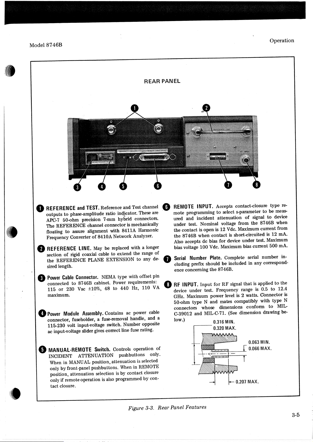
REFERENCE
o
outputs
APC-7
The REFERENCE channel connector
floating
Frequency Converter
REFERENCE
•
section
the REFERENCE PLANE EXTENSION to any
sired length.
Power
•
connected to 8746B cabinet. Power requirements:
or
115
maximum.
Power
e
connector, fuseholder, a fuse-removal handle, and a
115-230 volt input-voltage switch. Number opposite
ac input-voltage slider
and
phase-amplitude ratio in<llcator. These are
to
50-ohm·precision 7-mm hybrid connectors.
assure alignment with 8411A Harmonic
to
LINE.
rigid coaxial cable to extend the range of
of
Conne~tor.
Cable
Vac
230
Module
8410A Network Analyzer.
of
be replaced with a longer
May
NEMA
±10%, 48 to 440 Hz, 110
Assembly.
Contains
correct line· fuse rating.
gives
type
ac
mechanically
is
with
Reference and Test channel
TEST.
REAR
de-
pin
offset
VA
power cable
PANEL
Accepts contact-closure type
select s-parameter
open
the
to
12 Vde. Maximum current from
is
is
Maximum bias current 500
Complete serial number in-
Plate.
8746B.
RF
for
MIN.
0.316
MAX.
0.320
of
short-circuited
that
signal
2 watts. Connector
is
signal
applied
is
is
Number
INPUT.
,------
INPUT.
is
100Vdc.
Input
REMOTE
.0
mote programming
ured and incident attenuation
under test. Nominal voltage from the 8746B when
the contact
the 8746B when contact
Also accepts dc bias for device under test. Maximum
bias voltage
Serial
cluding prefix should be included in any correspond-
•
ence concerning
RF
•
device under test. Frequency range
GHz. Maximum power level
50-ohm type N and mates compatibly with type
connectors whose dimensions conform
C-39012 and MIL-C-71. (See dimension drawing below.)
to
to
is
0.5
re-
be meas-
device
rnA.
12
rnA.
the
to
12.4
to
MIL-
to
is
N
IVIANUAL-REMOTE
o
INCIDENT ATTENUATION pushbuttons only.
MANUAL
in
When
only by front-panel pushbuttons.
position, attenuation selection
only if remote operation
tact closure.
Switch.
position, attenuation
Controls operation of
in REMOTE
When
by contact closure
is
also programmed by con-
is
Figure
selected
is
3-3.
Panel Features
Rear
3-5
Page 19
Operation
8
11
Model 8746B
RF
INPUT
RF
INPUT~""'--
.....
~~r=---
.....
,--I
'.
T'
I I I
I IL
:
I 1 I
I
~(
I
J..!
L
__
---1
r
--l
10
dB
__
OUTPUT
!
10
dB
L
__
(.
I)
PORTl
-.J
TEST
CHAN
-
"I
~PORT2
C I
~
RF
INPUT~""--""'~~F-~""
3-6
I-~'
I
~(
I<j>
: 6
I I
I I
I
wl
L
__
---1
RF
INPUT------
r-
--l
<:.
I)PORTI
IL--~
OUTPUT
I
Figure 3-4. Standard Model
TEST
CHAN
RF
...........
Circuits
~=----
Page 20
•
Model
8"
RF
INPUT
8746B
Operation
RF
INPUT
r - E
r:
- -
-,
I10dB
IT
I I
,.
I
IX
I
Ii
L
IL_.-:._J
I
---<:~
.....~__
I
~l--I:....-_-
"I
__
-l
~d;-
L
~l~PORT
...
TEST
CHAN
~
~rl
( I)
--.J
PORT
1
2
INPUT~'
NOTE
No10dB
in
port
in
the
002.
RF
~-_
pad
couplers
....
-----*:--
---0""
__
--"
I.-~I
,10
dB
(
L
__
-.J
...
I)
TEST
CHAN
PORT
2
1:---'
I~:
I r I
I I
I
I
I
11
L
I
I
I
__
1--'
--!
Figure 3-5. Option 001 and
I - (
:
lOdB
L
___
\10
dB
L
__
3
(
-:
~
J )
J
-.-.J
I
I)
PORT
TEST
CHAN
PORT
1
1:---'
I~:
I r I
I I
I
I
I
11
L
__
2
.
002
RF
Circuits
I -
("
-l
)
PORT
1
IlodB
L
___
I
J
3
TEST
- I
~
CHAN
I)
PORT
-l
2
3-7
I
I
I
I
0
;-
.J
0d
(
L
__
Page 21
._d'
Operation
Table 3-2.
Operating
concerning operation
panel switchesonthe
transistor
transistor
If
and
to
under
the
8717A
Service .Manual
of
the
871 7Atocorrespondtothe
be
tested.
test, perform
is
used, refer
871 7A. Set
To
apply bias
the
following:
for
full details
CAUTION
These instructions are
or
transistors (PNP
NPN). Some
transistors may be damaged
bias in this order, while this is
order
for
other
FET's.
applying bias depends
upon
for
The
by
the
the
bipolar
applying
order
type
FET. Therefore, always .read
manufacturer's biasing instructions before
testing transistors.
your
procedure
Good
on
practice istotry
a similar,
inexpensive transistor, first.
a. Make Bias and Bias Sense connections
from
interconnect
8746B
to
8717A
cableisnot
output.
availabl~,
If
the
makeupa cable
to
the
to
FET
proper
of
of
the
but
8717A
its
front
the
using
Normally
circuit
Direction
the
and
connector
port
1 circuit is used
port
2
of
RF
signal flow depends
furnished
for
the
with
for
output-bias circuit.
parameter measured.
b.
Set
8717
A voltage METER FUNCTION
switch
AMPL
turn
0.1to0.3 volts
to
VcE
control
c. With
8717
Aon.
d.
Adjust
-D
s position and adjust VeE
full·y counterclockwise.
no
transistororcalibrator installed,
8717
AVe
E
-0
l
.
S AMPL
CAUTION
If
CCE
-0
S is set below 0.1 V,
base-collector
junction
may
forward-biased and draw excessive reverse
current. This
under
IIf
difficultyisfound
nearest
Hewlett-Packard
test.
may
when
office
damage
. .
setting
for
0.1to0.3
further
the
information.
Model
the
the
input-bias
upon
control
become
transistor
volts,
contact
8746B
8746B.
the
-0
to
your
S
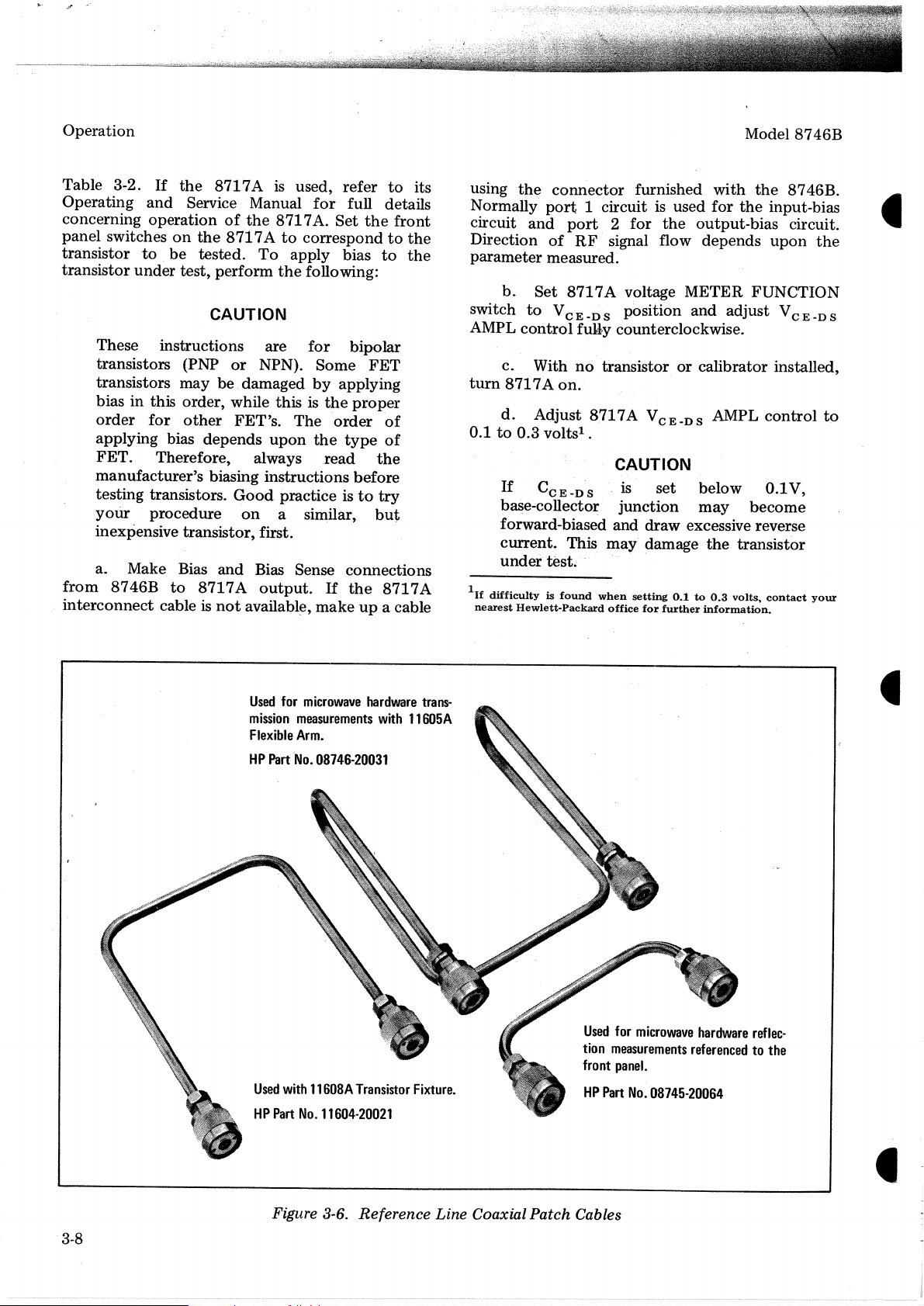
Used
for
mission
Flexible
HP
Part
Used
HP
Part
microwave
measurements
Arm.
No.
08746-20031
with
11608A
No.
11604·20021
hardware
with
Transistor
trans-
11605A
Fixture.
Used
for
tion
measurements
front
panel.
HP
Part
microwave
No.
08745-20064
hardware
referencedtothe
reflec-
3-8
Figure 3-6.
Reference
Line Coaxial Patch Cables
Page 22
Model 8746B
e.
Turn
the
8717A
f.
Set
8717AIE-8AMPL/RANGE
fully counterclockwise.
Set
IE
-8
g.
to
5,
50,
transistor
or
under
LIMIT(MA) current-limit switch
500
test.
bias. off.
rnA position
to
control
protect
the
m. Turn
terclockwise.
n.
Turn
0.3 volts.
o.
Turn BIAS off.
the
IE-8AMPL
VeE
AMPL
control
control
Operation
fully coun-
downto0.1
to
h.
Place
11608A
output
leadtothe
i.
Hold
striplinebyclosing
j.
Turn
to
desired
Set
k.
to
monitor
the
with
the
right.
the
BIAS on. Adjust
output
voltage.
current
-
I
and
E
8
transistor
input
transistor in
the
11608A
under
leadtothe
contact
lid.
VeE
'METER FUNCTION switch
adjust I
-
E
8
controltodesired collector current.
1.
instructed
If
biasisnot
BIAS switch
Make
in Figure 3-9.
transistor
CAUTION
turned
to
off, transients may
measurements as
down
befor~
damage sensitive transistors.
test
in
the
left
and
the
with
the
AMPL control
AMPL/RANGE
pushing
3-21. Bias Using a Dual
sistors may also
be
supply. Additional circuitry
sistor
under
test
maybeneeded.
may
take
the
formofdiodes
emitter
the
will vary with
3-22.
with
connected
voltage
and
and/or
a series current-limiting resistor
emitterorbase lead.
the
transistor used.
Note
that
the
either
to
is
normally
the
either
input
Bias Sense terminals
voltage connected
DC
Power Supply. Tran-
biased using a
to
between
The
particular circuit used
bias supplies canbeconnected
or
output
port
terminal.
connected
to
and
to
port
2 Bias
terminals (see Figure 3-8). This
also make
flow
Transistor
or
any
be
shorted readily,
from
other
the
normal
the
Fixture
left
(forward-gain) signal (S21)
to
is used. When using
application where
the
right
bias
when
the
current-limited.
dual
dc-power
protect
Protection
the
the
circuits
base
circuit voltage
The
input
the
port
1 Bias
the
output
and
circuit
Bias Sense
convention
the
11608A
the
11608A,
bias
supply
supply should
tran-
and
in
bias
will
can
be
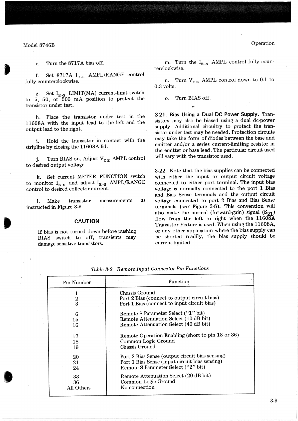
Table
3-2~
Remote
Input
Connector Pin Functions
Pin Number
1
2
3
6
15
16
17
18
19
20
21
Chassis Ground
Port
2 Bias (connecttooutput
Port
1 Bias (connecttoinput
Remote
Remote
Remote
S-
Parameter Select("1"
Attenuation
Attenuation
Remote Operation Enabling (short
Common Logic
Ground
Chassis Ground
Port
2 Bias Sense
Port
1 Bias Sense
24 Re,mote S-Parameter Select
33 Remote
Attenuation
36 Common Logic Ground
All Others No connection
Function
Select
Select (40 dB
(output
(input
circuit bias sensing)
Select
circuit bias)
circuit bias)
bit)
(10
dB bit)
bit)
to
pin18or
circuit bias sensing)
("2"
bit)
(20dBbit)
·:v
36)
3-9
Page 23
Operation
If
a greater current-carrying
leadisneeded,
leads. However,
graded. See
the
parallel
remote
following
CAUTION
If
the
Bias Sense leadisusedtocarry
rent,
-
its bias-sensing
graded
rent
flow.
by
the
voltage
capacity
the
Bias
bias-sensing
caution.
function
drop
duetothe
on
and
may
will
the
Bias
Bias Sense
be
de-
cur-
be
de-
cur-
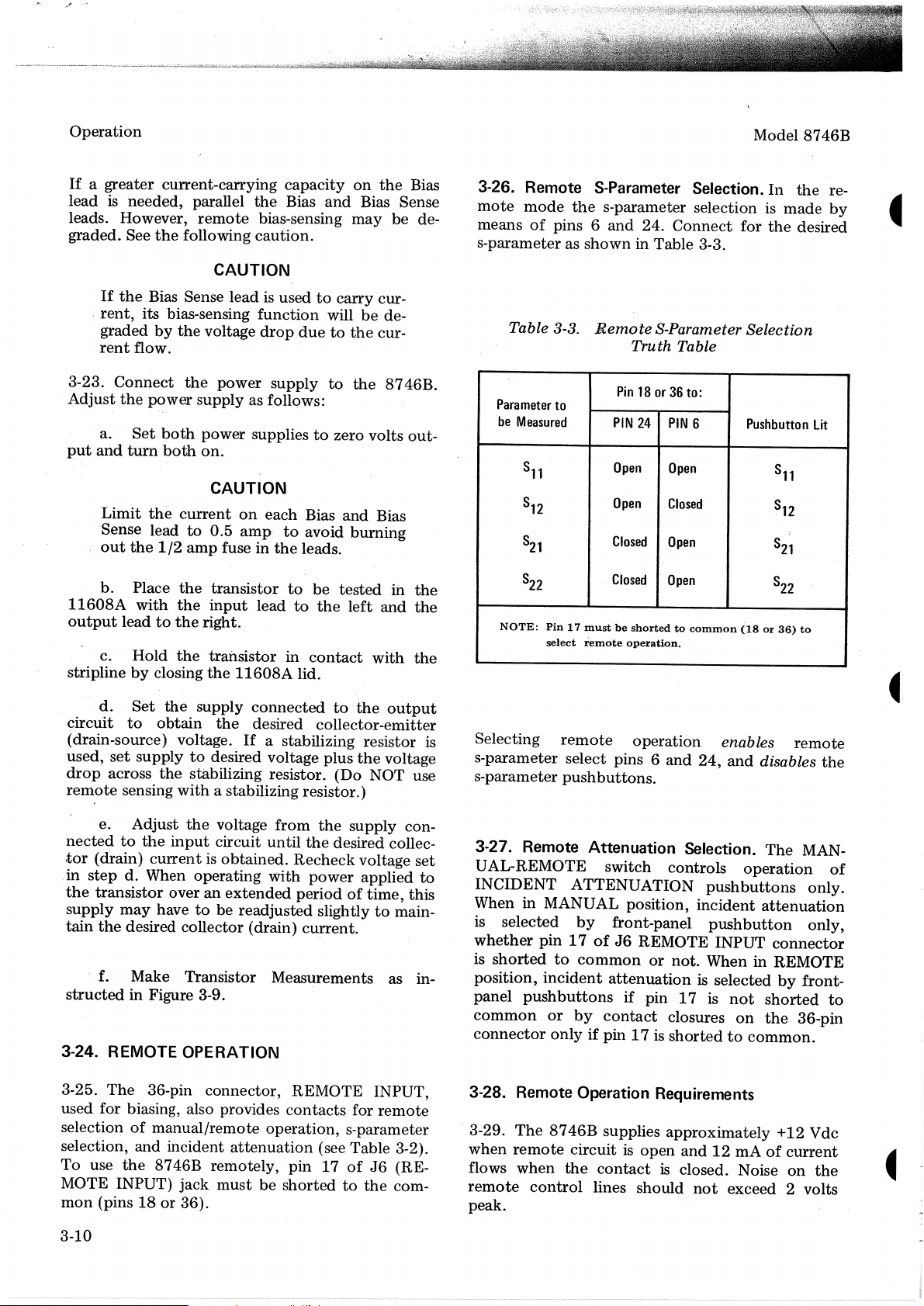
3-26. Remote S-Parameter Selection.
mote
mode
means
s-parameter as
Table 3-3.
of
the
pins 6
shown
s-parameter selection is
and
24.
Connect
for
in Table 3-3.
Remote
S-Parameter Selection
Truth Table
Model
In
made
the
8746B
the
re-
by
desired
3-23.
Adjust
a.
put
and
Connect
the
Set
turn
power
both
both
the
power
supply
supply as follows:
power
suppliestozero volts
on.
to
the
CAUTION
Limit
Sense lead
out
b.
11608A
output
c. Hold
striplinebyclosing
d.
circuit
(drain-source) voltage.
used,
drop
remote
e. Adjust
nectedtothe
tor
(drain)
in
stepd.When operating
the
transistor
supply
tain
the
the
current
the
1/2
Place
with
the
the
leadtothe
the
Set
the
to
obtain
to
amp
on
0.5 amp:
fuse in
transistor
input
right.
transistor in
the
11608A
supply
the
If
set
supplytodesired voltage
across
the
sensing
stabilizing resistor.
with
a stabilizing resistor.)
the
voltage
input
circuit
currentisobtained.
overanextended
may
havetobe readjusted slightlytomain-
desired collector (drain)
each
Bias
and
to
avoid
burning
the
leads.
to
be
tested
leadtothe
left
contact
lid.
connected
to
desired collector-emitter
a stabilizing resistor
plus
(Do
from
the
supply con-
until
the
desired collec-
Recheck
with
power
periodoftime,
cu~rent.
f. Make Transistor Measurements as in-
structed
in Figure 3-9.
3-24. REMOTE OPERATION
8746B.
Bias
in
and
with
the
output
the
voltage
NOT use
voltage
-applied
out-
the
the
the
set
to
this
Para
meter
to
be
Measured
8
11
8
12
8
21
8
22
NOTE:
Pin17mustbeshortedtocommon
select
is
Selecting
remote
s-parameter select pins 6
s-parameter
push
3-27. Remote Attenuation Selection.
UAL-REMOTE
INCIDENT ATTENUATION
When in MANUAL position,
is selected
whether
is
position,
panel
common
connector
pin17ofJ6REMOTE INPUT
shorted
to
incident
push
buttons
or
onlyifpin 17 is
Pin18or36to:
PIN
24
PIN
remote
Open
Open
Closed
Closed
operation.
operation
6
Open
Closed
Open
Open
and
24,
Pushbutton
(18or36)
enables
and
disables
buttons.
The
switch
controls
operation
pushbuttons
by
front-panel
common
or
incident
pushbutton
not.
When in REMOTE
attenuation
attenuationisselectedbyfront-
if
pin
17isnot
by
contact
closures
on
shortedtocommon.
Lit
8
11
8
12
8
21
8
22
to
remote
MAN-
only.
only,
connector
shorted
the
36-pin
the
of
to
3-25.
The
36-pin connector, REMOTE INPUT,
used for biasing, also provides
selectionofmanual/remote
selection, and incident
To
use
the
8746B
MOTE INPUT)
mon
(pins18or
remotely, pin
jack
must
36).
operation,
attenuation
be
3-10
contacts
for
s-parameter
(see Table 3-2).
17ofJ6
shortedtothe
remote
(RE-
com-
3-28. Remote Operation Requirements
3-29.
The
when
flows
remote
peak.
8746B
remote
when
control
supplies
circuitisopen
the
contact
lines should
approximately
and12rnAofcurrent
is closed. Noise
not
exceed 2 volts
+12 Vdc
on
the
Page 24
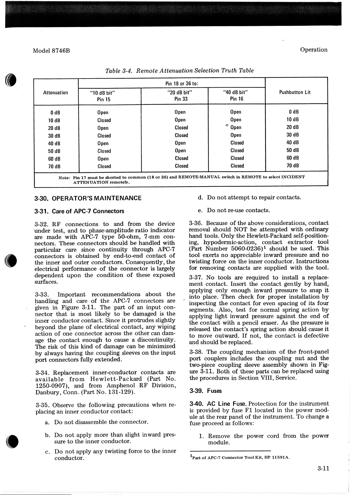
Model
8746B
Operation
Attenuation
o
dB
10
dB
20
dB
30
dB
40
dB
50
dB
60
dB
70
dB
Note:
"10dBbit" "20dBbit"
Pin17mustbeshortedtocommon
ATTENUATION
3-30. OPERATOR'S
3-31.
CareofAPC-7 Connectors
3-32.
RF
connections
under
are
nectors. These
test,
made
andtophase-amplitude
with
APC-7
connectors
particular care since
connectorsisobtained
the
inner"
and
outer
conductors.
electrical performance
dependent
upon
the
surfaces.
3-33.
p.andling
~ven
nector
inner
beyond
Important
and
in Figure 3-11.
that.ismost
conductor
the
planeofelectrical
actionofone
the
age
The
by
port
contact
riskofthis kindofdamage
always having
connectors
3-34. Replacement
available
1250-0907),
Danbury,
from
and
Conn. (Part No.
recommendations
care
of
contact.
connector
enoughtocause a
the
fully
extended.
inner-conductor
Hewlett-Packard
from
Table 3-4.
Pin
15
Open
Closed
Open
Closed
Open
Closed
Open
Closed
remotely.
Remote
(18or36)
MAINTENANCE
to
and
from
type
50-ohm, 7-mm con-
ratio
the
indicator
shouldbehandled
continuity
by
end-to-end
through
contact
Consequently,
of
the
condition
connector
of
is largely
these exposed
about
the
APC-7 connectors are
The
part
of
an
input
likely
to
be
damaged is
Sinceitprotrudes
across
contact,
the
other
any
can dam-
discontinuity.
canbeminimized
coupling sleevesonthe
contacts
(Part No.
Amphenol
RF
Division,
131-129).
Attenuation Selection Truth Table
Pin18or36to:
"40
dB
Pin
and
device
33
Open
Open
Closed
Closed
Open
Open
Closed
Closed
REMOTE-MANUAL
d.
Do
e.
Do
3-36. Becauseofthe
Pin
16
Open
Open
£Jf..
Open
Open
Closed
Closed
Closed
Closed
switchinREMOTEtoselect
not
attempttorepair
not
re-use contacts.
removal should NOT
hand
tools.
Only
the
with
APC-7
of
the
ing, .hypodermic-action,
(Part
Number
tool
exertsnoappreciable inward pressure
twisting force
for removing
5060-0236)1
on
the
contacts
3-37. No tools are
ment
the
con-
the
slightly
wiping
input
contact.
applying
r
into
place.
inspecting
segments. Also,
applying light inward pressure against
the
contact
released
to
and
3-38.
port
the
move
shouldbereplaced.
The
couplers includes
Insert
only
enough inward pressuretosnap
Then
check
the
contact
test
with a pencil eraser. As
contact's
outward.Ifnot,
coupling mechanismofthe
two-piece coupling sleeve assembly
are
ure 3-11.
the
3-39.
Bothofthese parts canbereplaced using
proceduresinSection VIII, Service.
Fuses
bit"
Pushbutton
o
dB
10
dB
20
dB
30
dB
40
dB
50
dB
60
dB
70
dB
INCIDENT
Lit
contacts.
above considerations,
be
attempted
with
contact
ordinary
Hewlett-Packard self-position-
contact
should
extractor
be
used. This
and
inner
conductor.
are supplied
required
the
contact
for
proper
to
Instructions
with
the
install a replace-
gently
by
installation
for even spacingofits four
for
normal
spring
the
action
contact
spring
the
sl)'Ould
action
the
end
pressure is
cause
is defective
front-panel
the
coupling
nut
and
showninFig-
tool
no
tool.
hand,
it
by
by
of
it
the
3-35. Observe
placing
a.
b.
an
Do
Do
inner
not
not
suretothe
c.
Do
not
conductor.
the
following precautions
conductor
disassemble
apply
inner
a.pply
contact.:
the
more
than
conductor.
any
twisting forcetothe
when
connector.
slight inward pres-
re-
inner
3-40.
AC
Line
Fuse.
is
providedbyfuse
uleatthe
rear panelofthe
F1
fuse proceed as follows:
1. Remove
the
power
module.
part
1
of
APC-7
Connector
Tool
Protection
located in
.for
the
the
instrument.Tochange a
cord
from
Kit,HP11591A.
instrument
power mod-
the
power
3-11
Page 25
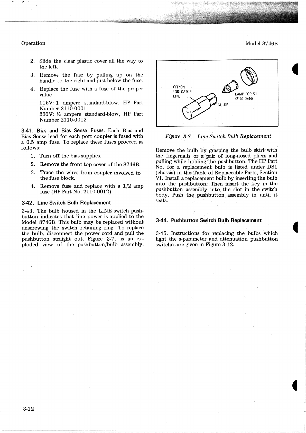
Operation
Model 8746B
2. Slide
3. Remove
4. Replace
3-41.
Bias Sense lead
a
follows:
0.5
Bias
amp
1.
2. Remove
3.
4.
the
clear plastic cover all
the
left.
the
handletothe
the
value:
115V:
Number
230V:
Number
Tum
Trace
the
Remove fuse
fuse (HP
1 ampere standard-blow, HP
2110-0001
1
ampere standard-blow, HP
12
2110-0012
and
Bias
for
fuse.
To
off
the
the
the
wires
fuse block.
Part
fuse
by
pulling
right
and
just
fuse
with
a fuseofthe
Sense Fuses. Each Bias
each
port
coupler
replace these fuses
bias supplies.
front
top
coverofthe
from
coupler
and
replace
No.
2110-0012).
witha1/2
3-42. Line Switch Bulb Replacement
3-43.
button
Model
unscrewing
the
·pushbutton
ploded
The
indicates
8746B.
bulb,
bulb
This
the
disconnect
straight
view
of
housedinthe
that
line
bulb
switch retaining ring.
the
out.
the
pushbutton/bulb
LINE switch push-
power
may be replaced
power
Figure 3-7. is an ex-
is appliedtothe
cord
the
way
up
on
below
the
proper
is fused
proceed
8746B
involved
without
To
replace
and
pull
assembl~T.
to
the
fuse.
Part
Part
and
with
to
amp
the
as
..
OFF-ON
INDICATOR
LINE
Figure 3-7.
Remove the·
the
fingernails
pulling while nQl<1illgthe·
No.
forareplacement
(chassis)inthe: TableofReplaceable
VI. Install a
into
the
pushbutto
pushbutton
body.
seats.
Push
Line
bulb
by. grasping
or
a pair
replacement
•·
assembly
the.
Il
pushbutton
A)
GUIDE
Switch Bulb
of
pushbutton.
bulb
bulbbyinserting
:Then insert
into..the
~
LAMP
FOR
(2140-0244)
the
long-nosed pliers
is listed
slotinthe
assembly
51
Replacement
bulb
skirt';:
The
under
P~ts,
the
the
keyinthe
in
3-44. Pushbutton Switch Bulb Replacement
3-45.
Instructions
the
light
switches
s-parameter
are
giveninFigure 3-12.
for
and
replacing
attenuation
the
bulbs
pushbutton
with
and
HP
Part
DS1
Section
bulb
switch
until
.which
it
3-12
Page 26
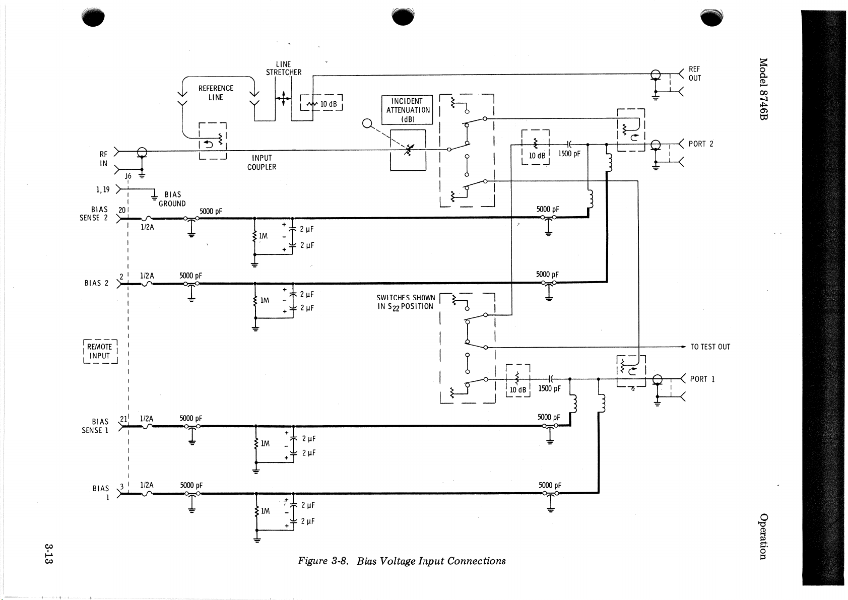
1,19
BIAS
SENSE
BIAS
REFERENCE
!
LI
NE
r--,
I I
~
I
~
RF
IN,"
J6
-::-
>:
20
2
~
2 I
2
~
l
BIAS
I -
I
I
I
I "
I . +
I
I '="
GROUND
1I2A
lI2A
O=<lr
'="
5000
0=0
L
SOOO
pF
_.J
pF
1
LINE
STRETc.HER
tj+
.,.
I - l
L:
1~B-.J
. . I
~
-
~
I
~
I
Q I I
I 0 I I i i
INPUT
COUPLER
~
1M
1
+ 2
-1
-r
IJF
2
IJF
+1
LM
_I 2
+ T 2
\.IF
\.IF
'"
I
~
L-J
SWITCHES
IN
S22
POSITION
I I I I
I I
I
~
L
- I
SHOWN
Ih
I
..
.-J
~
0 :
n
: I
'-I
,Q
~.
I
~O
pF
°1=
"="
F
s=
~~~
-=
r-"l
I(
,
,I
~
I
1''1
, (
PORT
2
8..
~
~
m
~
~
~
jREMOTEl
L!~~-l
BI
SENSE
BI
I
: I :
:
I
AS
21'
1I2A
II
I
I
I
I
I
AS
3 I
112
A
1
~
SOOO
"="
SOOO
0:-0
1
-=
pF
pF
-=
1+
1M
"="
1+
1M
I,
(I
~~('
-I~
2IJF
2IJF
+~
1
\"
2
IJF
-1
+T
2IJF
Figure 3-8. Bias Voltage Input Connections
5000
O=<r
-=
pF
I.
'I
If)
i
(PORT1
TO
TEST
OUT
~
~
~
~
0
::i
Page 27
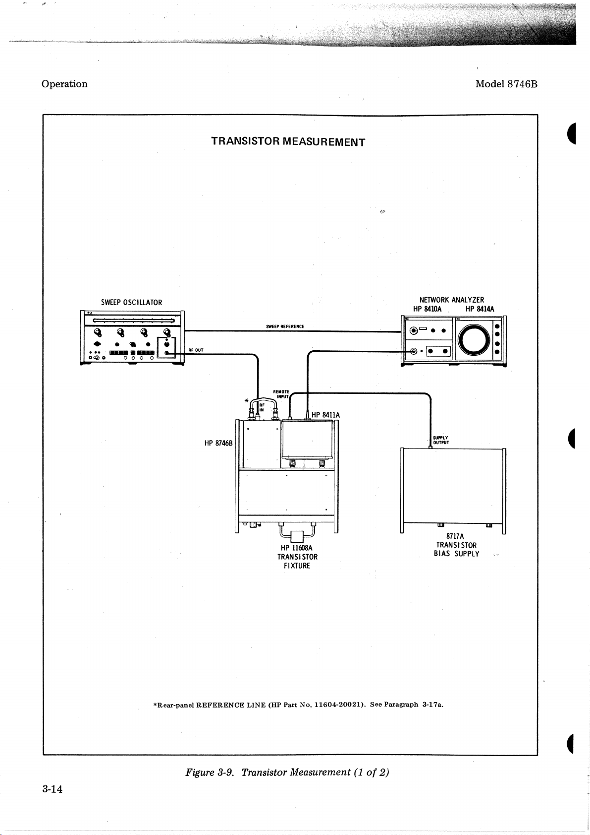
.:::1'
Operation
-
_.lI
o
OG2)
SWEEP
:
:
~
•
••
10
OSCILLATOR
:
:
:
Q
•
•
....
000
-
::: :
~
•
.-
0
RF
~l
OUT
-
TRANSISTOR
SWEEP
""""'il
MEASUREM
REFERENCE
r
ENT
HP
c:.
@t=Je
e·~
-
NETWORK
8410A
e
Model
ANALYZER
HP
8414A
leo
O~
-
8746B
HP
*~n~[
..
8746B
"OUllJ'w'
REMOTE
..
::
~
toJ
HP
11608A
TRANSISTOR
FIXTURE
HP
84IIA
II
SUPPLY
.
OUTPUT
-I'
WJI
8717A
TRANSISTOR
BIAS
SUPPLY
WI
3-14
*Rear-panel
REFERENCE
LINE
(HP
Part
No.
11604-20021).
Figure 3-9. Transistor Measurement(1of
See
Paragraph
2)
3-17a.
Page 28
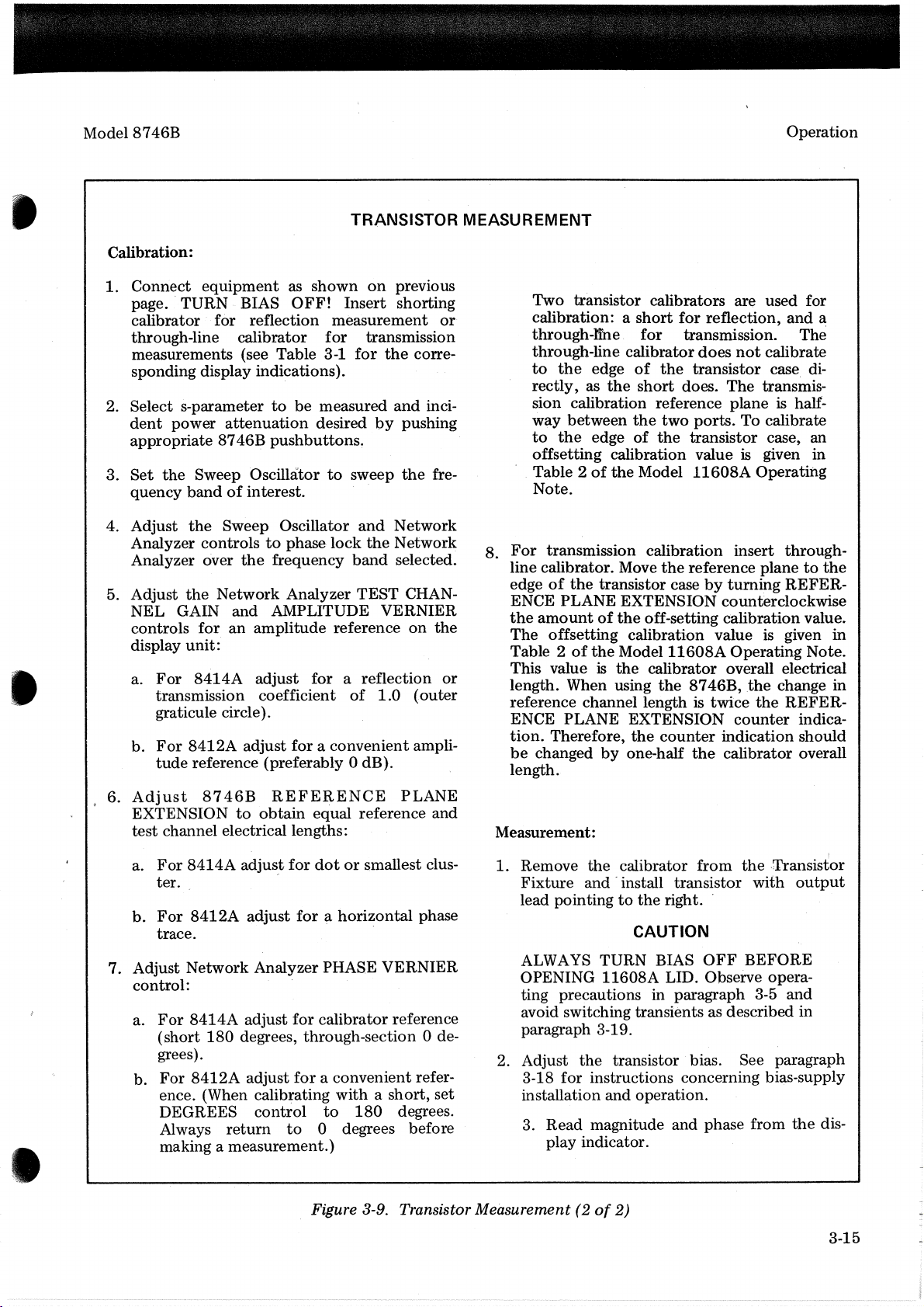
•
Model
8746B
Calibration:
1.
Connect
page
calibrator for reflection
through-line calibrator
measurements (see Table 3-1
sponding display indications).
2. Select s-parameter
dent
appropriate 8746B
3.
Set
quency
4. Adjust
Analyzer controlstophase
Analyzer over
5. Adjust
NEL
controls
display
a.
b.
equipment
..
TURN
power
the
Sweep Oscillatortosweep
bandofinterest.
the
the
GAIN
for
unit:
For
8414A
transmission coefficient
graticule circle).
For
8412A
tude
reference (preferably 0 dB).
as
shown
BIAS
attenuation
Sweep Oscillator
the
Network
and
an
adjust
OFF!
for
to
be
measured
desired
pushbuttons~
frequency
Analyzer
AMPLITUDE
amplitude
adjust
for a
foraconvenient
TRANSISTOR MEASUREMENT
on
previous
Insert
measurement
lock
reference
of
shorting
transmission
for
the
and
by
pushing
the
and
Network
the
Network
band
selected.
TEST
CHAN-
VERNIER
on
reflection
1.0
or
corre-
inci-
fre-
8.
the
or
(outer
ampli-
Two transistor calibrators are used for
calibration: a
through-lihe
through-line calibrator
to
rectly,asthe
sion calibration reference plane
way
to
offsetting calibration valueisgiven
Table 2ofthe
Note.
For
line calibrator. Move
edgeofthe
ENCE PLANE EXTENSION counterclockwise
the
amountofthe
The
Table 2ofthe
This value
length. When using
reference channel length is
ENCE PLANE EXTENSION
tion.
be
changed
length.
Operation
short
for
reflection,
for
transmission.
does
not
the
edge
of
the
transistor
short
does.
The
between
the
transmission calibration insert through-
offsetting calibration value is given
Therefore,
the
two
ports.
edge
of
the
transistor case, an
Model
transistor casebyturning
off-setting calibration value.
Model
is
the
the
by
one-half
11608A
the
reference planetothe
11608A
calibrator overall electrical
the
counter
Operating Note.
8746B,
twice
counter
indication should
the
calibrator overall
and
The
calibrate
case di-
transmis-
is half-
To calibrate
in
Operating
REFER-
the
change
the
REFER-
indica-
a
in
in
6.
Adjust
EXTENSIONtoobtain
test
a.
b.
7. Adjust Network Analyzer PHASE
control:
a.
b.
8746B
channel electrical lengths:
For
8414A
ter. . .
For
8412A
trace. .
For
8414A
(short
grees).
For
ence. (When calibrating
DEGREES
Always
making a measurement.)
180
8412A
REFERENCE
equal reference and
adjust
degrees, through-section 0 de-
return
adjust
adjust
adjust
control
for
dotorsmallest clus-
for
t;l
horizontal
for
calibrator reference
for
a convenient refer-
withashort,
to
180
to
0 degrees before
Figure 3-9. Transistor Measurement (2
PLANE
phase
VERNIER
set
degrees.
Measurement:
1.
Remove
Fixture
lead pointingtothe
ALWAYS TURN BIAS
OPENING
ting precautions in paragraph 3-5
avoid switching transients as described in
paragraph 3-19.
2. Adjust
3-18
installation and operation.
3. Read magnitude and phase from
the
calibrator
and install transistor with
CAUTION
11608A
the
transistor bias. See paragraph
for
instructions concerning bias-supply
play indicator.
of
2)
from
the
right
..
OFF
LID. Observe opera-
BEFORE
·Transistor
output
and
the
dis-
3-15
Page 29
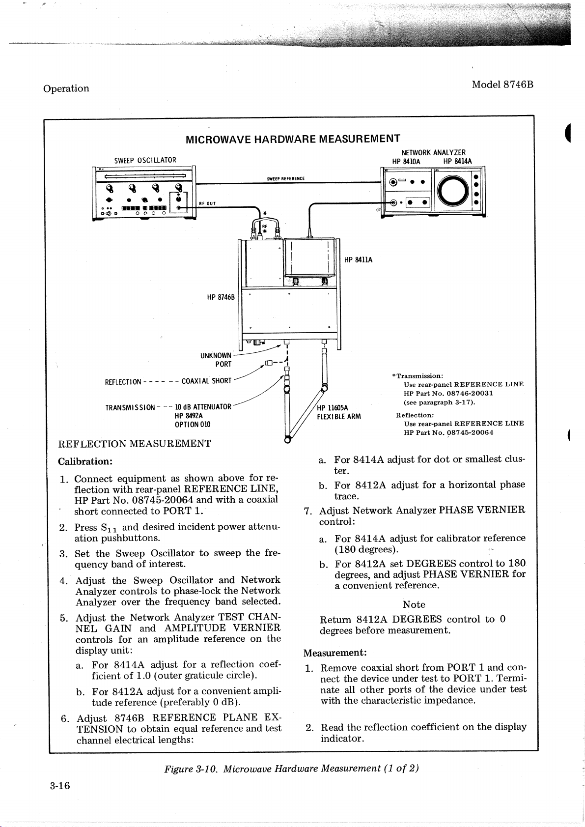
Operation
SWEEP
~ ~
• •
o@
(»
Hll-.1Il
OSCI
••
0
Q
....
(')
0 0
LLATOR
MICROWAVE HARDWARE M.EASUREMENT
HP
SWEEP
1------------------111
RF
OUT
HP
87468
REFERENCE
~
I
I
@c:::;).
~----__+It_*).~
HP
84IIA
NETWORK
8410A
ANALYZER
• •
Model
HP
8414A
0 ·
,:1
8746B
REFLECTION
Calibration:
1.
Connect
flection
HP
short
2. Press S11
3.
ation
Set
/'
quency
Adjust
4.
Analyzer
Analyzer over
Adjust
5.
NEL
controls
display
a.
b.
6.
Adjust
TENSION
channel electrical lengths:
REFlECTION
TRANSMISSION---10dB
- - - - - -
COAXIAL
HP
OPTION
MEASUREMENT
equipmentasshown
with
rear-panel
Part
No.
08745-20064
connectedtoPORT
and
desired
incident
pushbuttons.
the
Sweep Oscillatortosweep
bandofinterest.
the
Sweep Oscillator
controlstophase-lock
the
frequency
the
GAIN
for
Network
and
an
Analyzer TEST CHAN-
AMPLITUDE
amplitude
unit:
For
8414A
ficient
For
8412A
tude
reference (preferably 0 dB).
8746B
adjust for a reflection coef-
of
1.0
(outer
adjust
graticule circle).
for
REFERENCE
to
obtain
equal reference
UNKNOWN~
PORT
/
SHORT
/'
ATIENUATOR
8492A
010
above
REFERENCE
and
with a coaxial
1.
power
and
band
reference
a convenient ampli-
for
LINE,
attenu-
the
Network
the
Network
selected.
VERNIER
on
PLANE EX-
and
£0--1
re-
fre-
the
test
:
HP
llOO5A
FLEXIBLE
ARM
For
a.
ter.
b.
For
trace.
7. Adjust
control:
a.
For
(180
b.
For
degrees,
a convenientreference.
Return
degrees
Measurement:
1. Remove coaxial
nect
the
nate
all
with
the
2. Read
the
indicator.
*
Transmission:
Use
8414A
8412A
Network
8414A
rear-panel
HP
Part
(see
paragraph
Reflection:
Use
rear-panel
HP
Part
adjust
for
adjust
forahorizontal
Analyzer PHASE
adjust
for
REFERENCE
No.
08746..20031
3-1
REFERENCE
No.
08745-20064
dotorsmallest clus-
calibrator
degrees).
8412A
set
DEGREES
and
adjust PHASE
controlto180
VERNIER
Note
8412A
before
device
other
DEGREES
measurement.
short
from
under
testtoPORT
portsofthe
control
PORT1and
device
characteristic impedance.
reflection coefficientonthe
7).
VERNIER
reference
to
1. Termi-
under
display
LINE
LINE
phase
for
0
con-
test
3-16
Figure 3-10. Microwave Hardware
Measurement(1of
2)
Page 30
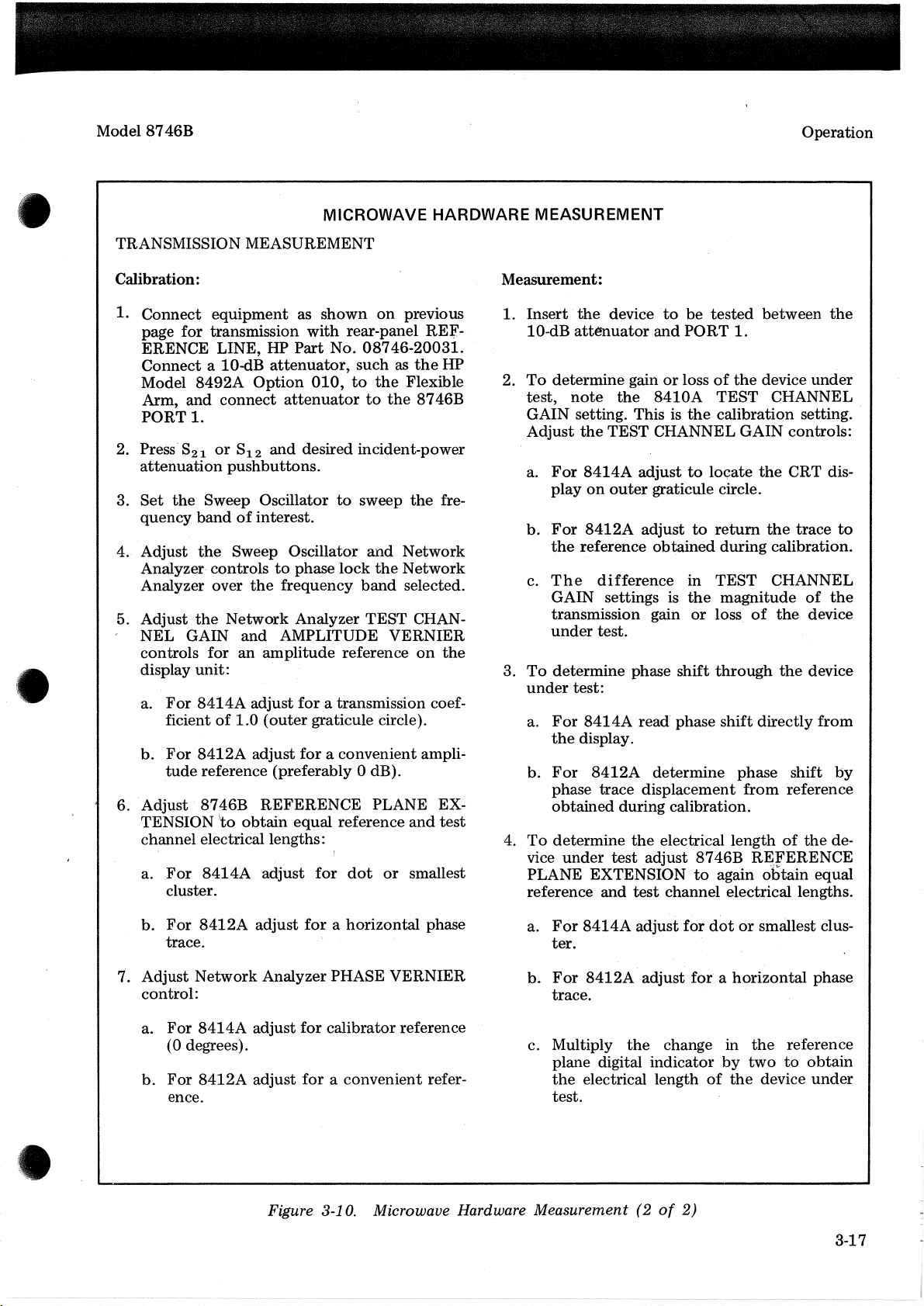
Model
8746B
Operation
•
MICROWAVE HARDWARE
TRANSMISSION MEASUREMENT
Calibration:
1.
Connect
page for transmission
ERENCE LINE, HP
Connect
Model
Arm, and
PORT
2. Press'821or
attenuation
3.
Set
quency
4. Adjust
Analyzer- controlstophase
Analyzer over
5. Adjust
NEL
controls for
display
a.
b.
6. Adjust 8746B
TENSION
channel electrical lengths:
a.
equipment
aID-dB
8492A
connect
1.
S12
pushbuttons.
the
Sweep Oscillatortosweep
bandofinterest.
the
Sweep Oscillator
the
the
Network
GAIN
unit:
For
ficient
For
tude
For
cluster.
and
an
8414A
8412A
reference (preferably 0 dB).
8414A
of
to
adjust
1.0
obtain
as
with
Part
attenuator,
Option
amplitude
(outer
adjust
REFERENCE
adjust
010,
attenuatortothe
and
desired incident-power
frequency
Analyzer
AMPLITUDE
fora
graticule circle).
for
equal
for
shown
rear-panel REE-
No.
suchasthe
to
lock
reference
transmission coef-
a convenient ampli-
reference
dot
on
previous
08746-20031.
HP
the
Flexible
8746B
the
fre-
and
Network
the
Network
band
selected.
TEST
CHAN-
VERNIER
on
the
PLANE EX-
and
test
or
smallest
MEASUREMENT
Measurement:
1.
Insert
10-dB
2.
To
test,
GAIN setting. This is
Adjust
a.
b.
c.
To
3.
under
a.
b.
4.
To
vice
PLANE EXTENSION
reference and
the
device ·to be
attenuator
determine
note
For
play
For
the
The
GAIN settings is
transmission gain
under
determine
For
the
For
phase trace displacement
obtained
determine
under
the
the
TEST CHANNEL GAIN controls:
8414A
on
outer
8412A
reference
difference
test.
test:
8414A
display.
8412A
during calibration.
test
tested
and
PORT
gainorlossofthe
8410A
the
adjusttoIOGate
graticule circle.
adjusttoreturn
obtained
in
the
or
phase shift
read' phase
determine phase shift
the
electrical lengthofthe
adjust
test
8746B
to
channel electrical lengths.
between
1.
device
TEST
calibration setting
the
the
during calibration.
TEST
magnitude
loss
of
through
shift
directly
from
REFERENCE
again o"litain equal
the
under
CHANNEL
CRT dis-
trace
to
CHANNEL
of
the
the
device
the
device
from
by
reference
de-
..
For
b.
'7.
Adjust Network Analyzer PHASE
control:
a.
b.
8412A
trace.
For
8414A
(0 degrees).
For
8412A
ence.
adjust
adjust
adjust
for
for
for
Figure 3-10. Microwave Hardware Measurement(2of
a horizontal phase
VERNIER
calibrator reference
a convenient refer-
a.
For
8414A
ter.
b.
For
8412A
trace.
c. Multiply
plane digital indicator
the
electrical lengthofthe
test.
adjust for
adjust
the
dotorsmallest clus-
forahorizontal
change in
2)
by
the
two
reference
to
device
phase
obtain
under
3-17
Page 31

Operation
APc-7 CONNECTORS
COUPLING
NUT
COUPLING
SLEEVE
Model
8746B
USE
To Connect:
1. On one connector,
by turning the coupling.
until the sleeve and
2. On the other connector, fully extend thecoup-
ling sleeve by turning the coupling
wise. To engage coupling sleeve and coupling
nut when the sleeve is fully retracted, press
back lightly on the
wise.
3. Push the connectors firmly together, and thread
the coupling nut
tracted sleeve over the extended sleeve. Leave
the
other
coupling
closing the gap between coupling nuts tends
loosen the electrical connection.
To
Disconnect:
1. Loosen the coupling
ing the wider gold band
retr~ct
nut
of
nut
the coupling sleeve
nut
counterclockwise
disengage.
nut
clock-
nut
while turningitclock-
the connector with re-
in the original position:
nutofthe connector show-
...
to
CARE
1. Keep contacting surfaces smooth and clean.
Irregularities
electrical performance.
COUPLING
CONTACTING
SURFACES
2. Protect the contacting surfaces when the connector is
sleeve extended.
SLEEVE
not
and··
foreign particles can degrade
in use by leaving the coupling
2. IMPORTANT: Part the connectors carefully
prevent striking the inner conductor contact.
3-18
Figure
to
3-11.
APC-7
Use
3.
Connectors
lintless material and/or firm-bristled brush
such
as
toothbrush for cleaning.Ifa cleaning
is
fluid
TANT: Do
hydrocarbons, esters, ethers, terpenes, higher
alcohols, ketones,
benzene, toluene, turpentine, dioxane, gasoline,
cellosolve acetate,
exposure
cleaning fluid and itsvapors as brief as possible.
needed use isopropyl alcohol. IMPOR-
not
of
use aromatic
or
ether-alcohols such
or
the
carbon tetrachloride. Keep
connector partstoboth
or
chlorinated
as
the
Page 32

Model
8746B
A bulb extractor tool,HPPart No. 4040-0427, has been developedtofacilitate bulb replacement for backlighted
pushbutton switches
BULB REPLACEMENT PROCEDURE
1. Place the endofthe thumbofone hand over the cornerofthe pushbutton switch. With the bulb extractor
tool in the other hand, place the hooked end
pushbutton (A) and gently push up until the lower end
of
the type shown below.
of
the
tool into
of
the
the pushbutton lens pops
frontofthe slot.onthe
outasshown in
bottomofthe
Operation
B.
•
A
2.
Remove the pushbutton lens. Place the hollow endofthe
and gently pull back. The bulb should stick in the extractor and come
pulled backasshown in
C.
bulb extractor tool over the bulbtobe replaced
B
outofits socket as
the
extractor
!~~'~.
.
3. Remove the old bulb from
to
the extractor
gently twist until
4. Replace the pushbutton lens by first positioning
pushbutton and pressing
Only the pushbutton lens should be removed for bulb replacement. If the pushbutton
inadvertently pulled
the pushbutton into the front panel and push
der
hold the new bulb, insert the new bulb into the socket. To separate bulb and extractor,
it
easily slips
of
procedureisthe sameaspreviously given.
the
hollow endofthe
off
the
bulb.
the
bottomofthe lens into place as shown in
out
during replacement, remove lens from the pushbutton. Re-insert
Figure 3-12. Pushbutton Selector Bulb Replacement
extractor and insert the bulb into
the
tabs at the top.
NOTE
in
until pushbutton snaps in place. Remain-
D.
of
the'
the
lens into
hollow end. Using
the
topofthe
is
3-19/3-20
Page 33

Page 34

Model 8746B
PerformanceTests
4-1. INTRODUCTION
4-2. The procedures in this section
ment's
cations
All tests can
interior
operational
Check"inSection III.
4-3. EQUIPMENT REQUIRED
4-4.
is listed
electrical performance using
of
Table 1-1 as
be
of
the
test
Equipment
in
the
performed
required for
the
performance standards.
without
instrument.
is needed, see
Recommended Test
If
the
performance tests
SECTION
PERFORMANCE
test
the
instru-
the
specifi--
accesstothe
only a simple
the
"Operator's
Equipment
IV
TESTS
Table in Section I. Any
the
critical speeifications given in
substituted
4-5. TEST RECORD
4-6. Results
lated
procedures.
specifications
results
for
comparison in periodic maintenance .and trou-
bleshooting
for
the
recommended model.
of
the
performance tests
on
the
Test·
The
Test
and
recordedatincoming inspection can be used
and
after
equipment
Record
Record lists allofthe
their
repairsoradjustments.
at
acceptable limits. Test
that
the
Table may
maybetabu-
the
end
satisfies
be
of
the
tested
•
4-7. Directivity
SPECIFICATIO
Directivity:
DESCRIPTION:
The
8746B under
coaxial short
sliding load. The Network Analyzer
making
If
to
duetothe
graticule circleisobserved, set
the
centerofthe
the
the
sliding load was a perfect termination,
the
directivity signal. However,
sliding load causing its reflected voltage vectortorotate
N:
~30
dB,
0.5to4.0
~26
dB,
4.0to12.4-GHz
testissetup
for
a reflection coefficientof1.
calibrationofthe
directivity signal plus
circle causedbyphasing
Polar Display's
GHz
as a reflectometerbyselecting S11or822.
The
test
channel gainisincreased
outer
graticule circle equaltothe
any
energy from
the
termination is
the
reflection from
the
Sweep OscillatortoCWatthe
the
sliding load
The
system is calibrated with a
short
is removed and
the
coupler's reverse arm would be
not
perfect. Thus
the
sliding load.Ifan indication greater
frequency in question.
around
mustbewithin
the
by
the
the
indication on
the
tipofthe
the
outer
8746B
directivity specification value,
directivity specification.
graticule circle.
is
terminated
the
Polar Display
than
Then
directivity vector. The
with a
due
only
the
outer
phase (slide)
is
4-1
Page 35

Performance
Tests
Mode18746B
4-7. Directivity (cont'd)
«)~
S
WEEPOSCI
:
::
~
....
[UIIIJIJ
«)
Q
LLA
:::::
~
.....
0
('I
0 0
PERFORMANCE
TOR
SWEEP
REFERENCE
~-------t~;'''''
l,...,I;[::J:::::q~DLJ-IO..J.:::E=-----4riiiI13-
SLI
DING
LOAD
- - - - -
TESTS
TEST
,'1
/ I
/ I
"" I
-"
"
NETWORK
--ill.
CAL
I
:
I
@c::::J
.~
HARMONIC
FREQUENCY
CONVERTER
-..
ANALYZER
I)
.~.
--=.::~~.
.:~:-.
·
•
•
.
~
COAXIAL
SHORT
EQUIPMENT:
SWEEP
NETWORK
HARMONIC
SLIDING LOAD
COAXIAL
REFERENCE
OSCILLATOR
ANALYZER
FREQUENCY
..
SHORT
LINE
PROCEDURE:
a.
Connect
the
equipmentasshown.
2tomeasure. When measuring
shorttoport
b.
the
bandofinterest.
c.' Push
position
d.
traceonthe
being
measured.
Adjust Sweep Oscillator
and
hold
the
controlstoplace
Adjust
Network
outer
graticule circle.
the
Analyzer
Figure 4-1. Directivity Test
. . . . . . . HP
Mode18690A,Bwith
. . . . . . . . . . HP Model
CONVERTER
....
Setup
. . . . . HP Model
. . . . . . .
8691-4A,
8410A/8414A
..
HP Model 90:5A
. . . . . . . . . . . HP Model
HP
Part
No.
08745-20064
Set
PORT1,select
and
Network
8414A
dotinthe
BEAM
centerofthe
TEST
8746B
S11.
Analyzer
CENTER
CHANNEL
for0dB
attenuation.
When measuring
controlstophase
pushbutton
graticule.
GAIN
and
AMPL
PORT
and
Select
2, select
lock
the
adjust
the
VERNIER
either
Network
horizontal
B plug
in
8411A
11565A
PORT1or
822.
Connect
PORT
coaxial
Analyzer
and
vertical
controlstolocate
<
over
the
4-2
Page 36

Model 8746B
Performance Tests
PERFORMANCE TESTS
•
4-7 Directivity (oont'd)
e. Remove Coaxial
GHz, use HP Model
f. Increase Network Analyzer
to
12.-5
GHz. - -
g.
Set Sweep
h.
Phase
Sliding Load must
directivity plus
i.
Repeat steps a
909A
Os~.illator
the
Sliding Load while observing
be
within
the
fixed
load
throughhto
Short
Option
to
the
reflection
and terminate
HOI Coaxial Termination.
TEST
sweep very slowly across
outer
graticule circle.
mustbewithin
test
directivityofthe
test
port
CHANNEL GAINby3{),
the
8414A.
the
being measured with a Sliding Load. Below
dll
for
0.5to4.0 GHzor26 dB
the
frequency
The
For
frequencies below
outer
graticule circle.
.other
test
bandofinterest.
centerofthe
port.
circle causedbyphasing
1.8
GHz,
the
display
for
1.8
4.0
the
of
4-8. Source Match 1
SPECIFICATION:
~1.3
(p
VSWR:
(Specification appliestostandard model only.)
DESCRIPTION:
Source
the
coaxial short. The displayed trace
reflectionischanged approximately
circuit. is also marked
traces
lEquivalent
matchistestedbymeasuring
reflected signal is varied. A swept-amplitude displayofa
at
any
source
=0.13) (when used
on
the
frequency shouldbeless
reflection
coefficient
with
the
is
marked
18-0°
oscilloscope
than
8411A)
change in magnitudeofa
on
the
by
removing
with
a grease pencil.
2.3 dB (voltage ratioof1.3:1).
miximum
oscilloscope
the
coaxial
The
maximum
with
short.
maximum
reflection when
reflectionisobtained
a grease penciL
The
displayed traceofthe
difference
the
when
The
phaseofthe
between
phase
of
using a
open
these two
4-3
Page 37

Performance Tests
4-8 Source Match (cont'd)
SWEEP
OSCILLATOR
PERFORMANCE TESTS
...
S_WE_EP_R_EF_ER_E_NC_E
-------
..
II@e;;t..
NETWORK
M.ode18746B
ANALYZER
ascI
D
Ir--------.I
0000
-.@
O
-;;: ...,
EQUIPMENT:
SWEEP OSCILLATOR
.-
SW~.EP-
OUT
LLOSCOPE
..
~~-""
HORtZ
0 0 0
_I @ 0
o-rO
O
~O-='
-;Q;'
VERT
IN
IN
,.----
87468
COAXIAL
SHORT
Figure 4-2. Source Match Test
HP Model
Setup
.........
~te).
HARMONIC
FREQUENCY
CONVERTER
PORT
2
8690
Series with
~
AMPL
-
OUT
RF
unit
as
requi~~d
NETWORK ANALYZER
. HP Model
HARMONIC FREQUENCY CONVERTER
OSCILLOSCOPE
COAXIAL SHORT . .
REFERENCE LINE
PROCEDURE:
a. Connect
2
to
measure. When measuring
shorttoport
b.
Adjust
swept-amplitude display over
the
equipment
being measured.
Sweep
as shown. Set 8746B for 0 dB
PORT
Oscillator,
the
1 select
Sll.
Network Analyzer, and Oscilloscope controls
frequency bandofinterest.
When measuring PORT 2 select 822. Connect coaxial
..
c. Calibrate Oscilloscope vertical sensitivitytodisplay 1 dB/em.
4-4
8410A
with
Gain Indicator
. . . . . . . HP Model
. . HP Model
180A/1801A/1821A
HP Model
. . . HP
attenuation.
Part
No.
Select either PORT 1orPORT
8413A
Phase-
8411A
11561A
08745-20064
to
obtain
a
Page 38

Model
4-8. Source Match (cont'd)
8746B
d.
Draw
the
Oscilloscope
PERFORMANCE TESTS
traceonthe
faceofthe
CRT
with
a grease pencil.
Performance Tests
e.
Remove
the
Coaxial
pencil.
f.
The
maximum
difference
This specification appliestothe
g.
12.4
GHz.
h.
Repeat
Repeat
steps a
steps a
throughffor
throughgto
Short
standard
and
draw
between
model
other
test
source
the
traceofthe
tracesatany
8746B
only.
open
circuitonthe
frequency should
faceofCRT
not
exceed 2.3
frequency segments as necessarytocover
matchofthe
other
test
port.
T
2.3dB
1
dB
the
rangeof0.5
with
a grease
(1.3 SWR).
to
4-9. Return Match 1
SPECIFICATION:
VSWR:
~1.3
(p
=0.13)
(Specification appliestostandard
DESCRIPTION:
Return
reflectometer
lReflection
matchofeach
setup
canceling,atsingle frequencies,
coefficientofport
test
portistested
usedtoterminate
model only.)
using
device
under
the
test.
internal
the
coupler
coupler
directivity
associated with
and
Flexible Arm reflections.
the
other
test
portina
4-5
Page 39

·-f
.-
Performance Tests
4-9. Return Match (cont'd)
SWEEP
::
~ ~
• •
e••.........
O<.@
0 0 0 0 0
OSCILLATOR
.:::::
,
••
PERFORMANCE TESTS
SWEEP
REFERENCE
......
------------
,..----~re)
NETWORK
..
11
@=..
•
HARMONIC
FREQUENCY
CONVERTER
[!=::!J
ANALYZER
8)
"'=0_
.--~
Model 8746B
·
:
•
EQUIPMENT:
SWEEP OSCIL.LATOR HP Model
NETWORK ANALYZER HP Model
HARMONIC FREQUENCY CONVERTER HP Model
FLEXIBLE ARM HP Model
COAXIAL SHORT . . . . . . . . . . . . . . . . HP Model
SLIDING LOAD . . . HP
REFERENCE LINE . . . . . . . . . . . . . HP
PROCEDURE:
a. Connect
2tomeasure.
SLIDING
pa::(JG=
the
equipment
COAXIAL
a:::J)o-----
LOAD
mtI
BELOW1.8
FIXED
SHORT
...
GHz
LOAD
--:::'~""~"""~ll
- - -
Figure 4-3.
,,/
",
Return
FLEXIBLE
HP Model:909A
as shown. Set 8746B
ARM
Match Test
Setup
8690
Series
with
RF
'~nit
as required
8410A
with
8414A
Display
Unit
8411A
11605A
11565A
Model905A
Option
for
0 dB attenuation. Select either PORT 1orPORT
HOI Coaxial Termination.)
(Below
Part
1.8
No. 08746-20031
GHz use
4-6
1.
When measuring PORT 1
and
Select S22-
2. When measuring PORT 2
and select
811.
return
return
match, connect long sectionofthe
match, connect long sectionofthe
Flexible ArmtoPORT
Flexible ArmtoPORT I
2
Page 40

Model 8746B
Performance Tests
PERFORMANCE TESTS
•
4-9. Return Match (cont'd)
b.
Connect a coaxial
c. Adjust-,Sweep Oscillator
the
frequency
d.
position controls
e. Adjust
trace
on
frequency range being swept.
f. Rempve
measured.
g.
standard
the
reflection coefficient does
directivity from
bandofinterest.
Push
and
hold
the
to
place
the
Network
the
outer
the
Increase Network Analyzer TEST CHANNEL GAIN
model
1.
2. Disconnect Flexible Arm from
8746B
the
Set
the
greatest reflectiononthe
Analyzer
graticule circle.Ifthe
coaxial short
only.)
8746B reflection coefficient as follows:
Sweep OscillatortoCW
shorttothe
and
8414A
dotinthe
TEST
The
polar displayofreflection
not
meet
free
endofthe
Network Analyzer controlstophase
BEAM CENTER
centerofthe
CHANNEL GAIN
trace deviates
and
connect
specifications, separate
and
Polar Display.
the
port
Flexible Arm.
pushbutton
graticule.
and
from
the
free
end
coefficient shouldbewithin
select
the
frequency which correspondstothe
being measured.
~Jt,
and
AMPL
a circle
of
the
by18-dB.
the
Flexible Arm reflection
lock
the
Network
adjust
by
the
horizontal
VERNIER
more
Flexible Arm
(This specification appliestothe
controlstolocate
than5mm,
Analyzer"over
and
.narrow
to
the
the
outer
and
port
vertical
being
circle.
coupler
point
the
the
If
of
3. Connect a Sliding Load
Termination. While phasing
pushbutton,
centerofthe
Below
4.
Disconnect
measured.
1.
Repeat steps a
12.4
GHz. .
j. Repeat steps a
adjust
1.8
GHz, place
the
The
throughhfor
throughito
to
the
Flexible Arm. Below
the
Sliding Load
the
Polar Display vertical
circle caused
the
Sliding Load (or termination)
displayofreflection coefficient shouldbewithin
test
by
phasing
dot
indicationinthe
other
frequency segments as necessarytocover
return
matchofthe
the
Sliding
centerofthe
and
and
horizontaf
Loadinthe
and
other
1.8
GHz use
without
connect
test
port.
CRT graticule.
909A
pressing BEAM CENTER
position controlstoplace
centerofthe
Flexible Armtothe
the
Option
outer
graticule circle.
the
H68
CRT graticule.
port
rangeof0.5
Coaxial
the
being
to
4-7
Page 41

~,
,.'
Performance Tests
Hewlett-Packard Model
S-Parameter
Serial No.
Paragraph No.
4-7
4-8
Test
Table 4-1. Performance Test Record
8746B
Set
Test
Directivity:
0.5to4.0
4.0to12.4'GHz
Source Matchinvoltage ratio
(Standard model
only)
Test Performed
GHz
by
Date
~B'
- Minimum
30
26
dB
dB
Results
Actual
Model 8746B
Maximum
2.3 dB
4-9
Return Matchinreturn
(Standard model
only)
loss
18
dB
';L--
4-8
Page 42

Model
8746B
Adjustments
SECTION
ADJUSTMENTS
5-1. INTRODUCTION
5-2. This section provides instructions for adjust-
The
ing tIle ·8746B.
performed
supply voltage adjustments are
However,
be
within 48
made. No appreciable
tionofthe
Service Sheet. 6.
separately.
the
ac voltage
to
voltage adjustments will
5-3. EQUIPMENT REQUIRED
5-4.
Equipment
in
the
Recommended
Section I.
"A"
in
Equipment
the
Use column.
5-5. ELECTRICAL ADJUSTMENTS
5-6.
The
only electrical adjustments are power
supply
output
following adjustments can be
The
440
required
voltages.
order
inputtothe
Hz when this adjustment
warmup
for
Test..Equipment
for
adjustment is marked
The
of
not
is necessary. Loca-
adjustmentsislisted
adjustment
the
power
important.
8746B
be
found
Table .in
locations
must
on
V
are shown
manual). With
±10%,48to
a. Connect
an-d
is
Adjust
±O.5V.
b.
and
Adjust
±O.5V.
5-7. MECHANICAL ADJUSTMENTS
5-8.
counter
clutch, refer
on
Service
anacinput
4~O
Al
TP3 with positive lead going
AIR14
Connect
Al
TP3 with negative lead going
AIR17-(-25V
The
friction clutch.
only
to
(+25V ADJ)
m.echanical
Figure 5-1.
Sheet
6 (last
voltageof115V/230V
Hz, proceed as follows.
voltmetertotest
for
voltmetertotest
ADJ)
for
adjustmentisthe
To
adjust
foldout
pointsAlTPI
a voltageof+25V
pointsAlTP2
a voltage
sheet
to
Al
TPI.
toAlTP2.
of
~25V
digital
this friction
in
I
i
I
I
I
5-1
Page 43

Adjustments
Model 8746B
FRICTION CLUTCH ADJUSTMENT
2 3
5-2
Remove
1.
2. Loosen
holding
(2)
shaft.
the
3. Hold
washer
tightening
(2).
4. Check
follows:
a. Adjust
EXTENSION
reads all zeros.
8746B
the
two hollow hex-head screws
the
the
collar tightly against
the
flattening
(3)
the
operation
the
the
top
collar
hollow
REFERENCE PLANE
crank
Figure
cover.'
in position
(1)
washer, while
the
the
on
spring
hex-head screws
clutch as
the
of
until
Digital Counter Friction Clutch
5-1.
counter
b. Hold
cation
clockwise until
Release
Rotate
c.
stop
15
cate
Rotate
d.
until
ter
again.
zeros, readjust
repeat
and
retain zero indi-
thumbwheel
rotate
and
thumbwheel.
the
crank
the
is reached.
or
em
the
stop
the
to
the
stop
the
clockwise
dial should indi-
The
reached.
is
until
the
counter-
crank
greater.
crank counterclockwise
coun-
reached.
is
The
dial should indicate all zeros
indicate all
the
not
friction
clutch
If
the
dial does
this check.
Adjustment
Page 44

Model
8746B
'Replaceable Parts
I
t,
I
REPLACEABLE
6-1. INTRODUCTION
6~2.
This
section
replaceable
is' available as
Exchange assemblies afford considerable
saving,
but
repairable assembly is
each
factory-repaired
bly.l
6-3. Table 6-1 gives
tions
and
reference designations
of
replaceable parts.
6-4. Table 6-2 is
is organized as follows:
a. Electrical assemblies
nents
in alpha-numerical
nation.
b.
Chassis-mounted
orderbyreference designation.
contains
parts.
The
step
eitheranewora
are
available
and
the
the
tableofreplaceable parts,
information
attenuator
for
assembly
rebuilt
ordering
assembly.
onlyona trade-in basis. A
required
tested
meaningsofthe
in
exchange
reuseable assem-
abbrevia-
usedinthe
and
their
orderbyreference desig-
parts
in' alpha-numerical
SECTION
A6
cost
for
table
and
compo-
VI
PARTS
c.
descriptionofthe
d.
typical
e.
the
code,
the
quantity
first
appearanceofthe
5-digit
Total
at
6-5. Table 6-3
that
correspond
bers.
ORDERING INFORMA'TION
6-6.
6-7.
To
orderapart
Table" provide
with
the
following
a.
The
Replaceable'Parts table.
b.
The
manufacturer
and
manufacturer's
for
each
contains
to
the
listed in
the
nearest
information:
Hewlett-Packard ,Part No.
quantity
required.
part,
of
the
number
partisgiven
part
the
names
only
number.
and
manufacturers'
the
Replaceable Parts
Hewlett-Packard
part
for
code
in
the
part.
once
-
addresses
num-
office
from
the
a
c.
Miscellaneous parts.
d.
Illustrated assembly drawings as follows:
Figure 6-1, Model
Figure 6-2,
Figure 6-3
all
inte~face
The
coupler
The
information
a.
b.
RF
IN
andisnot
The
total
Front
through
connectors
connector
Hewlett-Packard
quantity
8746B
Pan~l
Assembly
6-5
show
Front
Panel Assembly
replaceable
except
is
part
RF
of
separately replaceable.
given
for
each
part
consists of:
part
number,
(Qty)inthe
instrument,
parts
of
IN
(DC3Jl).
a directional
6-8.
To
orderapart
Parts table, provide
office
with
the
following
a.
Instrument
b.
Complete
c. Description
d.
Quantity
lWhen
ordering
assembly
part
extra
number
assemblies
only.
not
the
information:
model
serial
number,
and
functionofpart.
required.
Exchange
listedinthe
nearest
Hewlett-Packard
number.
including
for
spare
parts
assemblies
Replaceable
prefix.
stock,
require
use
trade-ins.
new
6-1
Page 45

Replaceable Parts
Model 8746B
A
B
BT
C
CP
CR
DC
DL
DS
E
A
AFC
AMPL
BFO
BECU
BH
BP
BRS
BWO
CCW
CER
CMO
COEF
COM
COMP
COMPL
CONN
CP
CRT
CW
DEPC
DR
ELECT
°ENCAP
EXT
F
FH
FILH
FXD
G
GE
GL
GRO
assembly
motor
battery
capacitor
coupler
diode
=
directional
delay
line
device
signaling
mise
electronic
amperes
automatic
control
amplifier
beat
frequency
tor
bery
llium
binder
head
bandpass
brass
backward
tor
counterclockwise
ceramic
cabinet
mount
coefficient
common
composition
complete
connector
cadmium
cathode-ray
clockwise
deposited
drive
electrolytic
encapsulated
external
farads
flat
Fillister
fixed
giga
germanium
glass
ground(ed)
head
(10
head
9
)
plate
Table 6-1. Reference Designators and Abbreviations Used in Parts
REFERENCE DESIGNATORS
plug
transistor
resistor
thermistor
switch
transftlnner
terminal
test
point
integrate~
normally
nominal
n~gative
zero
perature
ficient)
negative-positivenegative
not
for
placement
not
replaceable
order
description
oval
oxide
peak
printed
picofarads=10-
farads
phosphor
=
Phillips
peak
voltage
positive-negativepositive
part
polystrene
porcelain
position(s)
potentiometer
peak-to-peak
point
peak
age
rectifier
radio
round
right
positive
(zero
coef-
recommended
field
re-
separately
by
head
circuit
inverse
of
working
frequency
head
hand
board
circuit
open
teni-
12
bronze
volt-
or
coupler
frequency
oscilla-
copper
wave
oscilla-
only
tube
carbon
(lamp)
part
F
FL
J
K
L
LS
M
MK
MP
H
HDW
HEX
HG
HR
Hz
IF
IMPG
INCD
INCL
INS
INT
K
LH
LIN
LKWASH
LOG
LPF
M
MEG
METFLM
MET
OX
MFR
MHz
MINAT
MOM
MOS
MTG
MY
N
N/C
NE
NIPL
fuse
Filter
jack
relay
inductor
loud
meter
microphone
mechanical
henries
hardware
hexagonal
mercury
hour(s)
Hertz
intermediate
impregnated
='
incandescent
include(s)
insulation(
internal
kilo=1000
left
hand
linear
lock
logarithmic
low
pass
milli=10meg=10
metal
metallic
manufacturer
mega
miniature
momentary
metalized
substrate
mounting
"mylar"
nano
normally
neon
nickel
speaker
part
ABBREVIATIONS
freq
ed)
taper
washer
taper
filter
3
6
film
oxide
Hertz
9
(10-
)
closed
plate
P
Q
R
RT
S
T
TB
TP
U
N/O
NOM
NPO
NPN
NRFR
NSR
OBO
OH
OX
P
PC
Pf
PH
PHL
PIV
PNP
PIO
POLY
PORC
POS
POT
PP
PT
PWV
RECT
RF
RH
BRZ
List
V
VR
W
X
Y
Z
RMO
RMS
RWV
S-B
SCR
SE
SECT
SEMICON
SI
SIL
SL
SPG
SPL
SST
SR
STL
TA
TO
TGL
THD
TI
TOL
TRIM
TWT
f1
VAR
VOCW
WI
W
WIV
WW
WIO
vacuum
neon
photoce~
voltage
regulator
cable
socket
crystal
tuned
network
rack
mount
root-mean
reverse
voltage
slow-blow
screw
selenium
section(s)
semiconductor
silicon
silver
slide
spring
special
=
Stainless
split
ring
steel
tantalum
time
delay
toggle
thread
titanium
tolerance
trimmer
traveling
tube
micro=10-
variable
dc
working
with
watts
working
voltage
wirewound
without
tube,
bulb,
cavity,
working
steel
wave
inverse
etc.
only
square
6
volts
6-2
Page 46

I
!
I
•••.
f
f
I
,
!
•
'.".'.'
..
~"
I
Model
8746B
Reference
Designation
Al
AIel
AiC2
AIC.3
AIC4
AICRI
AICR2
AlCR3
AICR4
A1CR5
AICR6
AICRl
AICR8
AI'll
AI02
AIO.3
AIQ4
AI'l5
AIQ6
AIQ1
A1Q8
A1Rl
Al1<2
AIR3
AIR4
AIRS
AIR6
A1R1
AIRS
A1R9
AIRI0
AIRll
A1R12
AIR13
AIR14
AIR
15
AIR16
AIR11
AIR18
A2
A2Cl
A2C2
A2CRl
A2CR2
/l2CR.3
A2CR4
A2CR5
A2CR6
A2eR1
A2eR8
A2eR9
A2CRIO
A2CRll
A2CR12
A2eR13
A2CR14
A2CR15
A2CR16
A2eRl1
A2eR18
A2eR19
A2CR20
A2CR21
A2CR22
A2CR23
A2CI<24
A2eR25
A2CI<26
A2CR27
A2CR28
A2CI<29
A2CI<30
A2CR31
A2CR32
A201
HP
Part Number
08746-60052
0160-3451
0160-3451
0180-0141
0180-0141
1901-002~
1901-0029
1901-0029
1901-0029
1902-3193
1902-3193
1901-0029
1901-0029
1853-0020
1853-0050
1853-0012
1853-0052
l'854-C071
1854-0()71
1854-00~9
1854-0072
0764-0016
0764-0016
0698-3640
0151-C346
0151-0346
0698-3640
0157-0421
0151-0199
0751-C199
0151-0421
0811-1552
0813-0029
0698-3154
2100-1158
0751,-04~f
0151-043S
2100-1756
0698-3154
08146-60050
0180-1147
0180-1714
I·SCI-0025
19C2-o.041
1901-0025
1902-0041
1901-0025
1901-0025
1~02-0041
1901-0025
1901-0025
1902-0041
1901-0025
1901-0025
1901-0025
1902-0041
1901-0-025
1901-0025
1902-0041
1901-0025
1901-:0025
1901-0025
1902-0041
1901-0025
1901-(}'()25
I901-(W25
1902-0041
1902-0025
1901-0025
1901-0D25
1901",,0025
lc;02-31f2
lli02-Q049
1902-0041
1854-0C71
Table 6-2. ReplaceableParts
Qty
23
30
38
13
BOARD
1
C:fXD
2
C~XO
C:fXO
2
C:FXD
6
OIODE:SILICON
DIODE:SILICON
DIOOE:SILICON
OIODE:SILICON
OI.oOE
2
DIODE
OIODE:SILICON
OIOGf:SIlIeON
TSTR:SI
TSTR:SI
1
ISTR:SI
8
TSTR:SI
1
TSTR:SI
TSTR:SI NPN(SElEeTED
TSTR:SI
9
TSTR:SI·NPN
I
R~XD
2
R:FXD
R:FXD
2
R:fXD
2
R:FXO
R:FXO
R:fXD
2
R:FXO
2
R:fXD
R:fXDMET
R:fXDWW0.56
1
R:fXDWW1
1
R:FXD
2
R:VARW~lK
2
R:fXO
2
R~fXO
R:VARWWlK
R:fXO
BOARD
1
C:fXD
1
C:~XD
1
OIOOE:SILICON 100MA/IV
OIODE:6REAKDOWN
CICDE:SILICON
DIOOE:8REAKOCWN
OIOOE:SLLICON 100MA/IV
OlOOE:SllICON 100MA/IV
OIOOE:BREAKDGWN
DIODE:SIlICON 100MA/1V
DIGDE:SIlICON
DIODE:8REAKDOWN
DIGDE:SILICON 100MA/IV
OIOBE:SIlIGDH 100MA/IV
OIOOE:SILICCN 100MA/IV
DIODE:BREAKOOWN
DIODE:SIlICON 100MA/IV
DIOOE:SILICQN 100MA/IV
OIOOE:BREAKDOWN
OIDBE:SIlICON
OIODE:SIlICON 100MA/IV
DIQDE:SILICON 100MA/IV
OIOOE:BREAKCOWN
OIOOf:SILICCN 100MA/IV
OIOOE:SIlICON 100MA/IV
DIODE:SILICON 100MA/IV
DIOOE:BREAKDGWN
OlCOE,BREAKCOWN:I0.0V5%400
OIGDE:SI~ICON
OIOOE:SIlICON
DICDE:SILICON
DIODE
OIOOE:6REAKOOWN
OIODE:BREAKDVWN
lSTR:SI
Description
ASSY:POWER
CER
CER
·ElECl50·UF
ELECt50Uf +15-10%
BREAKDOWN:13.3V
BREAKDOWN:13.3V
PNP(SELECTED
PNP
PNP
PNP
NPNCSElECTEO
NPM
METFlH
,MET
METOXl.aK
NET
MET
METOX1.8K
MET
MET
MET
MET
NET
MET
MET
ASSY:8UFfER
ELECT
ELECT
BRfAKDCWN:SllIeON
NPNISElEeTEO
SUPPLY
0.01
.UF
+80-20~
Q.Ol Uf +80--20%
+15-10t
600
PIV
600
PIV
600
PIV
600
PIV
600
plv
600
PIV
1000
fila
flM10OHMl~1/8W
FLM10OHMIIIJ8W
fLM
fLH
fLM
flM
flM
fLM
FlM
FlM
OHM5&2W
1000
GHM512W
OHM512W
OHM5%2W
825
OHM
21.5K
OHM
21.5K
OHM
825
OHM
OHM5%2W
OHM313W
4.22K
5.11K
S.IIK
4.22K
Uf
201
Uf
101
5.11V
IDOMA/IV
5.11V
5.11V
lOOMA/IV
5.11V
5.11V
S~IIV
IOOMA/IV
S.11V
5.11V
100MA/IV
lOOMA/IV
lOOMA/IV
6.19V
5.1lV
OHM1%1/8W
OHM1%1/8W
OHM
OHM1&1/8W
OHM51TYPEVlW
CHM5&TYPEVIN
150
330
5%
51
FROM
FROM
FROM
1%
11
15VOCW
6VCCW
5&
5%
5%
5&
5&
5'
5&
51
5%
5%
fROM
100VOCW
100VOCW
50voew
50VOCW
2N3102)
2~3104)
2N3704)
1/8W
11
1/8N
1&
1/8W
1/8N
1%
1/SW
12.1V
2N3704)
MW
5%
Replaceable
Mfr
Code
28480
56289
56289
56289
~
56289
2848C
28480
28480
28480
28480
28480
28480
28480
28480
28480
80131
80131
28480
28480
80131
80131
28480
28480
28480
28480
28480
28480
28480
28480
28480
28480
28480
28480
28480
28480
28480
28480
28480
28480
28480
28480
28480
01263
04113
01263
04113
07263
01263
04113
01263
07263
04113
01263
07263
07263
04113
01263
07263
04113
01263
01263
07263
04113
01263
01263
01263
04113
28480
07263
01263
07263
28480
04113
04113
28480
Mfr
Part Number
08146-60.052
C0238101FI031S25-COH
C023BI01f1031S25-COH
300506G050002-0SM
300506G050002-05M
1901-0029
1901-0029
1901-0029
1901-0029
1902-3193
1902-3193
1901-0029
1901-0029
IS53-C020
IS53-0050
2N2904A
2N3140
1854-C011
1854-0011
2N3053
2N3054
0164-0016
0164-0016
069S-3640
0157-0346
0751-0346
0698-3640
0151-0421
0157-C199
0151-0199
0157-0421
0811-1552
OS13-0029
0698-3154
2100-1158
0157-0438
0157-0438
2100-1758
0698-3154
08146-60050
01S0-1141
01S0-1114
fO
2381
5l10939-98
FO
2381
Sl10939-98
FD
2381
FD
2381
51109139-98
fO
2381.:...
fO
23.81
Sl10939-98
fD
2381
fO
2381
fO
2381
Sl10939-98
fD
2381
FD
2381
Sl10939-98
fD
2381
FO
2381
fG
2381
5Z10939-98
fD
2381
fD·
2387
fO
2381
5l10939-98
1902-0025
fD
2387
fD
2381
FD
2381
1902-3182
5110939-122
5Z1093Cl)-98
1854-0071
Parts
See
introductiontothis
section
for
ordering
information
Page 47

Replaceable
Parts
Table 6-2. Replaceable Parts
Model
87468
Reference
Designation
A2Q2
A2Q3
A2Q4
A2Q5
A2Q6
A2Q7
Aloa
A2Q9
A2QI0
A2Qil
A2012
AlQ13
A2Ql4
A2Q15
A2Q16
A2Qll
A2Qi8
A2Q19
A2Q20
A2Q21
A2Q22
A2022
A2Q23
A2Q24
A2Q25
A2Q26
A2Q27
A2Ri
A2R2
A2R3
A2RLt
A2RS
A2R6
A2Rl
A2RB
A2R9
A2RlO
A2Aii
A2R12
A2R13
A2R14
A2R15
A2R16
A2R17
A2Rl8
j A2R19
A2R20
A2R2l
A2R22
A2R23
A2R24
A2R25
A2R26
A2R27
A2R28
A2R29
A2R30
A2R31
A2R32
A2R33
A2R3Lt
AlR35
A2R36
A2R31
A2R38
A2R39
A2R40
A2R41 0683-1-025
A2R42
A2R43
A2R44
A2R45
A2R46 Q.698-4261
A2R47
A2R48
A2R49 06<;8-4261
HP
Part Number
18S3-GC20
1854-0011
1853-0020
1854-0011
1853-0020
1854-0011
18'53-CC20
1854-0011
1853-0020
1854-0011
18'53.,.0020 TSTR:SI
1854-COll
1853-0020
1854-0011
1853-0020
1854-0011
1854-0011
1854-0011
1854-0011
1854-0071
1854-0062
1205-0048
1853-0012
1854-0039
1854-~071
1854-0C39
1853.-0C12
0698-4210
0683-1025
0698-4276
0151-0191
0698.,.4270
0683-1025
0698-4218
0698-4262
0151-C1S1
0698-4210
0683-1025
0698-421E
0151-0191
0698-4270
0683""!'1025
0698-4276
0157-0191
0698-4270
0.683-1,025
06~B-4218
0157-07<;1
0698-4270
0683-1025
0698-4218
0157...,0797
0698-4210
0683-1;Q25
0698-1t21e
0151-C1<;1
0698-4270
06e3-1025
0698-4276
0151-C1~7
0683-1025
0698~4261
G698-4242
0683-1025
0698-42fl
0698-4242
0683-1025
0683-1025
0698-4261
0698-4242
0683'"'!1G25
0:698-4242
0683-1025
Qty
12
33
18
12
TSIR:SI
TSTR:SI NPN(SElECTED
TSTR:SI
TSTR:SI
TSTR:SI
TSTR~SI
TSTR:SI
TSTR:SI
TSTR:SI ·PNP(SElECTED.
TSTR:SI
TSTR:SI ·NPNISElECTED
TSTR:SI ·PNPISElECTED
TSTR:SI
TSTR:SI
TSIR:SI
TSTR:SI
TSTR:SI
TSTR:SI
TSTR:SI NPNISElECTED
1
TSTR:SI
HEAT
1
TSTR:SI
TSTR:SI
TSTR:SI
TS1R:SI
TSTR:Sl
R:fXD
R:fXDCOMP
R:fXD
R:FXO
R:EXO
R:fXD
R:FXD
R:FXD
1
R:FXD
R:fXD
R:fXD
R:FXO
R:fXD
R:fXD
R:FXD
R:fXD
R:fXD
R:fXD
R:fXD teMP
R:fXD
R:FXD
R~fXD
R:FXD
R:FXD
R~XD
R:fXD
R:fXD
R:FXD
R:fXD
R:FXD
R:fXD
R:fXO"F.LM
R:FXD
R=fXD
5
R:FXD
R:fXD
5
R:FXD
R~FXD
R:fXD
R:FXO
R:fXD
R:fXD
R:fXD
R:fXD~lM
R:FXO
R:fXO flM
R:FXD
R:FXO
R~FXO
Description
PNPISElECTEO
PNP(SElECTED
NPNCSElECTED
PNP(SElECTED
NPH(SElECTED
PNPISElECTED
NPNISElECTED
~PN(SElECTED
PNPISElECTEO
·NPN(SElECTED
PNPISElECTED FROM'2N3702)
NPNtSElECTED
NPMtSElECTEO
NPNISElECTED
NPNISElECTED
NPN
SINK:FINNED?
PNP
NPN
·NPMJSElECTEO
HPN
PNP
flM
4.1K
1000
FLM
10K
MET
fLM
FlM
4.1K
COMP
1000
F~.
10K
FlM Z.2KOHM5S1/ew
MET
flM
fl~
4.1K
COMP
1000
FlM 10K
MET
flM
FLM
4.1K
CUHP
1000
fLM
10K
NET
ELM
flH
4.7K
1000
flM
10K
HET
FlM
fLK
4.1K
CCMP
1000
flM
10K
MET
ELM
flM
4.1K
COMP
1000
ELM
10K
MET
FlM
flH
4.7K
ceMP
1000
10K
MET
flM
GOMP
1000
flM2KOHM511/8W
flM
300
CDMP
1000
FLM2KOHM
flM
300
co~p
1000
CGMP
1000
COMP
1000
fLM2KOHM511/8W
300
CGMP
1000
2K
OHM511/8W
flM
300
teMP
1000
~lM
2K
OHM511/8W
FROM
fROM
FROM
fROM
fROM
fROM
FROM
FRCM
FROM
FROM
fROM
fROM
fROM
fROM
FROM
fROM
FROM
fROM
fROM
FOR
TO-8
fROM
OHM5.l/8W
OHM5~1/4W
tHM
51
li8N
90.9
OHMISlA2W
OHM5a1/8N
OHM
51 1/4W
OHM511/BW
90.9
OHM111A2W
OHM5S1/8N
OHM511/4W
OHM511/8W
90.9
OHMIS1A2W
~HM
5S
1/8W
OHM
51 1/4W
CHM511/8N
90.9
OHMII1/2W
OHM511i8N
OHM511/4W
OHM
5S 1/8W
90.9
OHMISIt2W
OHM511/8W
OHMIsa1/4W
OHM511/8W
90.9
OHMISlA2W
OHM511/8W
OHM511/4W
OHM511/8W
90.9
OHM111/2W
OHM511/8W
OHM511/4W
OHM5~1/8W
90.9
OHM
11 ll2W
OHM511/4W
OHM511/8W
OHM511/4W
51 1/8W
OHM
51 1/8W
51 1/4W
OHM
OHM511/4W
OHM5%1/4W
OHM511/8W
OHM5~1/4W
OHM511J8W
OH~
51 1/4W
2N3702)
2N3104)
2N31021
2N3704)
2N3702)
2N3704)
2N3702)
2N3704)
2N3702)
2N3104)
2-N31,02)
2~3104)
2N3102)
2N3104)
2N31~4)
2N3704)
ZN3704)
2N3704)
2N37041
CASE
2N3104)
Mfr
Code
28480
28480
28480
28480
28480
28480
28480
28480
28480
28480
28480
28480
28480
28480
28480
28480
28480
28480
28480
28480
80131
05820
80131
80131
28480
80131
80131
28480
01121
28480
28480
28480
01121
28480
28480
28480
28480
01121
28480
28480
28480
01121
28480
28480
28480
01121
28480
28480
28480
01121
28480
28480
28480
01121
28480
28480
28480
01121
28480
28480
01121
28480
28480
01121
28480
2848'0
01121
01121
01121
28480
28480
01121
28480
28480
01121
28480
Mfr
Part Number
1853-0020
185lt-CC71
1153-0020
1851t-0071
1853-0020
185lt-0071
1853-0020
185lt-C071
1853-0020
1854-0011
1853-0020
1854-.0011
1853-0020
1.-'854-0011
1853-0020
185lt-0071
1854-0071
1854-0071
1851t-0071
1854-0011
2N1701
213-C6
2N2904A
2N3053
1854-0071
2H3053
2N2904A
0698-4210
&8
1025
0698-4218
015'7-0191
0698-4270
C8
1025
0698-4218
0698-4262
0751-0191
0698-4270
C8
1025
0698-4278
0751-J)791
0698-4210
C8
1025
0698-427.
0157-.0797
0698-4210
CB
1025
0698-4218
0151-0791
0698-4210
C8
1025
0698-42,?;f!.
0151-.0791
0698-4210
CB
1025
0698-4278
0151-.0191
0698-4270
C8
1025
0698-4278
0151-0191
CB
1025
0698-4261
0698-4242
CB
1025
0698-4261
0698-4242
C8
1025
C8
1025
CB
1025
0698-4261
0698-42"2
C8
1025
0698-4261
0698-4242
C8
1025
0698-4261
See
introductiontothis
section
for
ordering
information
Page 48

Model
87468
Table 6-2. Replaceable Parts
Replaceable
Parts
Reference
Designation
A2R50
A2R51
A2R52
A2RS3
A2RS4
A2RSS
A2R56
A2RS1
A2RS8
A2R59
A2R60
A2R61
A2R62
A2R63
A2R64
A2R65
A2R66
A2R61
A2R68
A2R69
A2Ul
A2U2
A3
A3Cl
A3C2
A3C3
A3C4
A3C5
A3CR1
A3CR2
A3CR3
A3CR4
A3CRS
A3CR6
A3CRl
A3CR8
A3CR9
A3CRI0
A3CR11
A3CR12
A3CR13
A3CR14
A3CR15
A3CR16
A3CR11
A3CR18
A3CR19
A3CR20
A3CR21
A3CR22
A3CR23
A3CR24
A3c.R25
A3CR26
A3CR21
A3CR28
A3Q1
A3Q2
A303
A304
A305
A306
A301
A308
A3Q9
A3010
A3011
A3Q12
A3Q13
A3014
A3015
A3016
A3011
A3Q18
A3019
HP
Part Number
O~9·8-4242
0683-1025
0683-1025
0683-1025
0764-0013
"
0764-0013
0683-1025
0698-4218
0683-1025
0698-4240
0698
...
3t13
0683-1025
0683-1025
0698-4211
0683-1025
0683-2425
0683-3915
0683-1025
0698-4240
0683-0tf5
1820-0092
1820-0092
081'16-60051
0160-2930
0160-2S30
0160-2930
011:0-2930
0160-2930
1901-0025
1«302-0041
1901-00~5
1902-00/tl
1901-0025
1902-00/t1
1901-0025
1902.-00/t1
1902-0025
1901-0025
1901-0025
1901-0025
1901~O025
1902-3104
1902-3104
1901-0025
1901-0025
1,901-0025
1901-0025
1902-3104
I~C1-a025
1901-0025
1902-3104
1<902-3104
1901-0025
1«;01-0025
1901-0025
1901-Q025
1854-0011
1853-0020
1854-0011
1853-0020
1854'"'t0011
1853-0C20
1854-0011
1853-0020
1854-0()11
185/t-0039
1853-0020
1854-0011
1853-0012
1853-0020
1854-G071
1854-0C3~
1853-0.020
1854-0011
1853-0012
Qty
R:FXD
R:fXD
R:fXD
R:FXD
R:FXD
2
R:FXD
R:fXO
R:fXD
R:fXD
R:FXD
2
R~FXD
1
R:fXD
R:fXD
R:fXD
1
R:FXDCOHP
R:FXG
1
R:fXD
1
R:FXD
R:fXO
R:FXD
1
INTEGRATED
2
INTEGRATED
BOARI
1
C:FXD
6
C:FXD
C:~XD
C:FXD
C:fXD
DIOGE:SI.LICOH 100MA/IV
DIODE:8REAKDOWN
OIOOE:SILICON 100MAIlV
DIODE:8REAKOOWN
DIODE:SILICON lOOMA/lV
DIODE:BREAKDOWN
DI.ODE:SILICtJ,. lOOMA/lV
DI09E:8REAKOOWN
DIOOE.8REAKDDWN:IO.OV
DIOOE:SLlICGN 100MA/IV
OIOGE:SILIGON
DIODE:SlLICON 10OMA/IV
DIOOE:SILICON lOOMA/lV
OIODE:8REAKDOWN
5
OIOOE:8REAKOOWN
DIODE:SILICOH 100MAIIV
DIODE:SILJCON 100MA/1V
DIGOE:SILICCN 10OMA/IV
DIODE:SILICON 100MA/IV
DIODE:8REAKDOWN
DIODE:SILICON 100MA/lV
OIOGE:SILICON 100MA/lV
OIODE:BREAKDOWN
DI,oOE:BREAKDOWN
DIODE:S1LICON 100MA/IV
DIOOE:SILICON
DIODE:SIlICON 100MA/1V
DIODE:SLlICCN leOMA/IV
TSTR:SI
TSIR:Sl
TSTR:SI
TSTR:SI
TSTR:SI
TSTR:SI
TSTR:SI
TSTR:SI
TSTR:Sl
TSTR:SI
TSTR:SI
TSTR:SI
TSTR:SI
TSTR:SI
TSTR:SI
TSTR:Sl
TSTR:SI
TSTR:SI
TSTR:SI
Description
FLM
300
COMP
COMP
COMP
METOX56
METOX56
COMP
FLtOMP
METax39
COMP
FLM
~QNP
COMP
COMP
FLM
CGMP
CER
CER
CER
CER
CER
OHM5~1/8W
1000
OHM5~1/4W
1000
O~M
1000
OHM
OHM5.2..
OHMsa2W
1000
OHM5.1/4W
10K
OHM5.1/8N
1000
ELM
tLMP
ASSY:SWITCH
HPNISELECTED
HPNfSELECTED
NPNISELECTED
·NPN
PNPCSELECTED
OHM,5' 1/4W
240
OHM
OHM5~2M
1000
OHM5.114M
1000
OHM
5.1K
OHM511L8W
1000
OHM
2400
OHM
390
OHM
1000
OHM
240
OHM5.1L8N
6.8
~HM
CIRCUIT:SWIT~HING
CIRCUIT:SWITCHING
0.01
UF
0.01UF+80-20'
0.01
UF
0.01UF+80-201
0.01UF+80-20'
5.llV
5.11V
5.1lV
5.llV
IOOMA/IV
5.62V
5.62V
5.62V
5.62V
5.62V
100MAL1V
PNP«SELECTED
PNPISELECTED
PNP(SELECTED
NPNlSELECTED
PHPlSELECTED
NPN(SELECTED
NPNCSELECTED
PHP
PNP(SELECTED
NPN(SELECTED
NPI
PNPlSELECTED
NPI.SELECTED
PHP
51
5.
SI
1/8W
5.
5.
51
5.
1/4
5.
5.
l/4W
DRIVER
+80-201
+80-201
51
5'
51
51
51
51
51
51
51
51
FROM
FROM
FROM
FROM
fROM
FROM
fROM
FROM
FROM
FROM
fROM
FROM
fROM
FROM
FROM
1/4W
1/4W
114M
114M
114M
114M
..
/too
CONVERTER
CONVERTER
100VDCW
100VDCM
100VOCW
100VOCW
100VDCW
MW
2fi3704)
2N3102)
2N3704.
2N3702)
2N3704)
2N3702)
2N3104)
2N3702)
2N3104)
2-H3702
2·N31\(4)
2N3102)
2N3704)
2N3102)
2"3704)
Mfr
Code
28480
01121
01121
01121
~
)
28480
28480
01121
28480
01121
28480
28480
01121
01121
28480
01121
01121
01121
01121
28480
01121
28480
28480
28480
91418
91418
91412
91418
914lE
01263
04113
01263
04113
01263
04113
01263
04113
28480
01263
01263
01263
01263
04113
04113
01263
01263
01263
01263
04713
01263
01263
04113
0/t113
01263
01263
07263
07263
28480
28480
28480
28480
28480
28480
28480
28480
28480
80131
28480
28480
80131
28480
28480
80131
28480
28480
80131
Mfr
Part Number
0698-4242
C8
1025
C8
1025
C8
1025
0764-0013
0764-0013
C8
1025
0698-4218
C8
1025
0698-4240
0698-3613
C8
1025
CB
1025
0698-4211
C8
1025
CB
2425
C8 3915·
C8
1025
0698-4240
C868G5
1820-0092
1820-0092
08746-60051
TA
TA
TA
TA
TA
FD
2381
SZl0939-98
FD
2381
SZ10939-98
FD
2381
SZ10939-98
FD
2381
SZ10939-98
1902-0025
FO
2381
FD
2387
FO
2381
FD
2381
SZ10939-110
S110939-110
FD
2381
FO
2381
2387
FD
FO
2381
S110939-110
FD
2381
FO
2387-:"
S110939-110
S110939-11Q
FD
2387
FO
2381
FD
2381
FD
2381
1854-0011
1853-0020
1854-0011
1853"'0020
1854-:0011
1853-0020
1854-C011
1853-0020
1854-0011
2N3053
1853-0020
1854-C071
2N2904A
1853";0020
1854-0071
2N3053
1853-0020
1854-0011
2N2904A
See
introductiontothis
section
for
ordering
information
Page 49

Replaceable
Parts
Table 6-2. Replaceable Parts
Model
87468
Reference
Designation
A3020.
A3021
A3022
A3023
A3024
A3025
A3026
A3Q21
A3028
A3Q29
A3030
A3031
A3032
A3033
A3034
A3Q35
A3Q36
A3031
A3Q38
A3Rl
A3R2
A3R3
A3R4
A3R5
A3R6
A3R1
A3R8
A3R9
A3RI0
A3Rli
A3R12
A3R13
A3R14
A3R15
A3Rlb
A3Rl1
A3R18
A3R19
A3R20
A3R21
A3R22
A3R23
A3R24
A3R25
~
A3R26
A3R21
A3R28
A3R29
A3R30 06.98-427.2
A3R31
A3R32
A3R33
A3R34
A3R35
A3R36
A3R31
A3R38
A3R39
A3R40
A3R41
A3R42
A3R43
A3R44
A3R45
A3R46
A3R47
A3R48
A3R49
A3R50
A3R51
A3R52
A3R53
A3R54
A3R55
A3R56
HP
Part Number
1853-0020
1854-0011
1854-0C3S
1853-0020
1854-0011
1853-0012
1853-0020
1854-0011
1854-CD3S
1853-00.20
1854-0D71
1853-0012
1853-0020
1854-0011
1854-0.039
1853-CC20
1854-0011
1853-0012
1853-0020
06.~8-4210
0683
...
1025
06.98-4278
0151-C197
0698-4210
0683-1025
0698-4218
0698-4262
0757-0197
0698-4210
0663-1025
0698-4278
0151-G7S1
0698-4210
0683-1025
0698-4218
0157-07S1
0683-1025
0683-1025
0698-4278
0698-4278
0683-f6235
0683-6235
0698-425S
0698-4294
0698-4272
0698-4262
0698-425S
0698-42C;4
0698-42e2'
0757-0833
0757-0833
0757=0833
0757-0833
0683-1C15
0683-1015
0683-1015
0683-1015
0683-0335
0683-0335
0683-0335
0683-0335
0683-1025
0698-4218
0683-6235
Q698-42SS
0698-42S4
0698-4212
0698-4262
0757-0833
0757-0833
06B3-1C15
0683-1C15
0683-0335
0683-0335
Qty
10
TSIR:SI
TSTR:Sl
TSIR:SI
TSTR:SI
TSTR:SI
TSTR:SI
TSTR:Sl
TSIR:SI
TSTR:SI
TSTR:SI
TStTR:Sl NPNISELECTED
TSTR:SI
TSTR:SI
TSTR:SI
TSTR:SI
TSTR:SI
TSTR:SI
TSTR:SI
TSTR:SI
R:FXO
R:fXD
R:fXD
R:fXO
R:fXD
R:fXD
R:fXO
R:FXD
R:FXD
R:fXO ·FlM
R:FXD
R:fXD
R:FXD·.•MET
R:FXD
R~XD
R:FXD
R:fXD
R:FXD
R~XD
R:fXD
R:fXD
5
R:fXD
R:FXD
R:fXD
5
R:f.XO;~LM
5
R:~XD
5
R:.FXO
R:FXD
R:fXD
R:FXO
R:FXD
10
.R:.FXD
R:FXD
R:FXD
R:FXD
R:f=XD'
R:fXD·G.DMP
R:ifXD
R:FXO
R:fXD
10
R:fXD
R:FXD
R:FXD
R:FXD
R:FXD
R:fXD
R:fXD
R:FXD
R:rXO
R:FXD
R:FXD
R:FXD
R:FXD
R:fXD
R:fXD
R:FXD
Description
PNPISELECTfD
NPNI
SELECTED
NPN
PtiPISELECTED
NPNlSElECTED
PHP
PNPlSELEC~ED
NPNISElECTED
NPN
PNPISElECTEO
PNP
PHPfSELECTEO
NPNISELECTED
NPN
PNPISElECTED
NPMISELECTED
PHP
PNPISElECTED
flM
4.7K
OHM511i8W
COHP
1000
fLM
MET
Flit
CLMP
flM
flM
"ETflH
COMP
ELM
F.LM
COMP
FLM
MET
GGMP
COMP
FLM
FlM
CDMP
CCMP
fLM
flM
FLM
fLM
flM
ftM
lELM
MET.
MET.ELM-5--.11K
MET
MET
CD"P
COMP
COMP
GOMP
CDMP
CDMP
CDMP
CQMP
flM
C..cMP
flH
flM
ft~
fLM
MET
MET'
COMP
CGHP
COMP
COHP
OHM
10K
OHM
FlM
90.9
4.7K.OHM51IJ8W
1000
OHM
10K
OHM
2.2K
aHM
90.9
4.1~
~HM
1000
OHM
10K
OHM'5~
,flM
90.9
4.1K
OHM511l8W
1000
OHM511/4W
10K
OHM
,f.LK
90.9
1000
OHM51l/4W
1000
OHM
10K
OHM
10K
OHM51118W
62K
OHM511/4W
62KOHM
1.6K
OHM511/8W
41K
OHM
5.6K
OHM
2.2K
OHM
1.6K
OHM5111-8W
47K
OHM511/8W
5.6K
OHM
2.2K
OHM511/8W
FLM
5.11K
FLM
5.11K
FLM
5.11K
100
OHM
100
OHM
OH14
100
OHH
100
OHM
3.3
'OHM
3.3
3.3~HM
3.3
OHM
1000
OHM
10K
OHM511t8W
62K
OHM
1.6KOHM51
47K
OHM511/8W
5.6K
OHM511/8W
2.2K,OHM
FLM
5.11K
FLM
5.11K
100
GHM511/4W
100
OHM511i4W
3.3
,OHM
3.3
~HM
fROM
2N3702)
FI\OM~3704)
fROM
2H3102)
fROM
2N3104)
fROM
2H3~02)
FROM
2N3104)
FROM
2H3102)
fROM
2N3T04)
FROM
2N3102)
FROM
2~3104)
fROM
2"'3702)
FROM
2N3104)
fRGM
2N3?02)
5~
1/4W
51
ll8W
OHM111.42W
51
1/4
..
51
1/8W
511/8W
OHM
11
1/2W
51
lA8W
51
1/4W
It8W
OHM
11 1l2W
51
lAaW
OHM
11
1/2W
51
1/4W
51
1/8
..
51
1/4W
51
1/8W
51
1/8W
51
1/8
..
51
1/8W
OHM
1% 1/2W
OHM
1%
OHM
1%
OHM
1%
51
lilt
..
1/4W
51
1/4
..
51
1/4
..
51
1/4W
51
1/4
..
51
1/4W
51
51
li4
..
51
1/4W
51
1/4
..
1/8
..
51
1/8W
OHM
1%
OHM
1%
51
1/4
..
51
1/4W
1!2W
1/2W
1/2W
1/2W
1/2W
t~;1.
Mfr
Code
28480
28480
80131
28480
28480
80131
28480
28480
80131
28480
28480
80131
28480
28480
80131
28480
28480
80131
28480
28480
01121
28480
28480
28480
01121
28480
28480
28480
28480
01121
28480
28480
28480
01121
28480
28480
01121
01121
28480
28480
01121
01121
.28480
28480
28480
28480
28480
28480
28480
28480
284-80
28480
28480
6it~2
01121
01121
01121
01121
01121
01121
01121
01121
28480
01121
28480
28480
28480
28480
28480
28480
01121
01121
01121
01121
Mfr
Part Number
1853-0020
1854-0011
2N3053
1853-0020
1854-0071
2N2904A
1853-0020
1854-0011
2N3053
1853-0020
1854-0011
2N2904A
18.53-0020
1854-0011
2N3053
1853~OO20
1854-0011
2N2904A
·1853-0020
0698-427,0
CB
1025
0698-.4218
0157-D191
0698-4270
CB
1025
0698-4218
0698-4262
0757-0191
0698-4270
CB
1025
0698-4278
0157-0191
0698-4210
C8
1025
0698-4218
0757-.0191
CB
1025
CB
1025
0698-4218
0698-4218
C8
6235
CB
6235
0698-4259
0698-4294
0698-4212
0698-4262
0698-4259
0698-4294
0698-4272
0698-.~~62
0757-0833
0757-08J3
015·7-&833
2,5lo~~33
1015
CB
1015
CB
CB
1015
0335
CB
0335
C8
0335
CB
0335
CB
C8
1025
0698-4218
CB
6235
0698-4259
0698-4294
0698-4212
0698-4262
0757-0833
0757-0833
C8
1015
C8
1015
CB
0335
C8
0335
~
See
introductiontothis
section
for
ordering
information
Page 50

Model
8746B
Table 6-2. Replaceable Parts
Replace~ble
Parts
Reference
Designation
A3R51
A3R58
A3R59
A3R60
A3R61
A3R62
A3R63
A3R64
A3R65
A3R66
A3R61
A3R68
A3R69
A3R10
A3R11
A3R72
A3R13
A3R14
A3R15
A3R16
A3R11
A3R18
A3R19
A3R80
A3R81
A3R82
A4
A40S1
A40S1
A40S2
A4DS2
A40S3
A40S3
A4054
A40S4
A4055
A4055
A40S6
A4056
A40S1
A4DS7
A40S8
A40S8
A4059
A40S9
A40S10
A40S10
A40S11
A40S11
A40S12
A4DS12
A4S1
A4S1
A4S1
A452
A452
A4S2
A4S3
A4S3
A453
A454
A454
A454
A455
A455
A4S5
A4S6
A4S6
A456
A4S7
A4S7
A4S7
A458
A4S8
A458
HP
Part Number
0683
...
1;025
0-683-1025
0698-4278
0698-4278
0683-6235
0683-6235
0698-425,9
0698-4294
06.98-4272
0698-4262
0698-4259
06.98-4294
0698'!'"4272
0698-4262
0757-0833
0757-0833
0757-0833
0'757-UH33
0683-1015
0683-1015
0683-1015
0683-1015
0683-03;5
0683-0335
9683-0335
0683-0335
08146-60053
1450-0356
0370-0768
1450-0356
0370-0768
1450-0356
0370-0768
1450-0356
0370-0768
1450-.0356
0370-0768
1450-0356
0370-0768
1450-0356
0370-0768
1450-0356
0370-0768
1450-0356
0370-0768
1450
....
0356
0370-0768
1450-0356
0370-0768
1450-035t
0370-0768
1460-1223
0370-0921
5'OOO-~400
1460-1223
0370-0921
5000-6401
1460-1223
0310-0921
5000-6402
1460.-1223
0370-0921
5:000-6403
1460-1223
0310-0921
5000-S611
1460-1223
Q310--C921
SOOO-S618
1460-1223
0310..,0921
5000-8619
1460-1223
0310-0921
5000-S6S0
Qty
12
12
12
12
R:FXD
COMP
R:,FXD·
CDMP
R:FXD
ELM
R:FXD
flM
R:fXD
COMP
R:fXD
CC~P
R:FXD
FlH
R:FXD
flM
R:fXO fLM
R:fXD.;FLM
R:fXO
fl.M
R:fXO
FLM
R:FXD
Fl"
R:FXD
FLM
R:FXD
MET
R:FXD
R:FXD
R:FXD
R:FXD
COMP
R:fXD
COMP
R:FXD
CONP
R:fXD
COMP
R:fXD
COMP
R:FXD
ceMP
R:fXD
C~MP
R:FXO
COMP
BOARD
1
1
ASSY:SWITCH
LAMP:CLEAR
LENS:PUSHBUTIONJWHITE
LAHP:CLfARDOME
LENS:PUSHBUTTONJWHITE
LAMP:CLfAR
LENS:RUSH8UTTONJWHITE
LAKP:CLfAR
LENS:PUSH6UTTONJWHITE
LAHP:CLfAR
LENS.PUSHBUTTON,WHITE
LAHP:CLEARDOME
LENS:PUSHBUTTON,WHITE
LAMP:CLEAR
LENS:PUSHBUTTONJWHITE
LAMP:CLEAR
LENStPUSH8UTTON,WHITE
LAHP:ClEAR·OOME
LENS:PUSH8UTIONJWHITE
LAHP:CLEAR
LENS:PUSH8UTTONJWHITE
lAMP:ClEAR
LENS:PUSHBUTION,WHITE
LAMP:CLEARDOME.LENS
LENS:PUSHBUTTON,WHITE
SPRING:SWITCH
PUSHBUIT.ON:SWITCH,
LA8EL:PUSHBU~~O~
SPRING:SWITCH
PUSHBUTION:SWITCH,
LA8EL~USH8UTTON
SP.RING:SWITCH
PUSH8UTT~N:SWITCHt
lA8EL:P~SHBUTTON
SPRING:SWITCH
PUSH8UTTnN:SWITCH,
LABEL:PUSHBUTTON"
SPRING:S-WITCH
PUSHBUTION:SWITCH,
LA8EL:PUSHBUTTON
SPRING:SWITCH
PUSHBUJTDN:SWITCH.
lABEl:PUSHBUTTON
SPRING:SWITCH
PUSHBUTTON:S~ITCH.
LABEL:P.USHBUTTnN
SPRING:SWITCH
PUSHBUTtDN:SWITCH.
LABEL:PUSHBUTTON
1000
1000
10K
10K
62KOHM
62K
1.6K
47K
5.6KGHM.51
2.2K
i.6K
41K
5.6K
2.2K
FLM
MET
FLM
MET
FLM
MET
FLM
100
100
100
100
3.3
3.3
3.3
3.3
DOME
DOME
DOME
DOME
DOME
DGME
DOME.
DCME
Description
OHM
51
1/4W
OHM
51
OHM
OHM
OHM·
LENS
lENS
LENS
LENS
LENS
LENS
LENS
LENS
LENS
LENS
LENS
15111
IS12)
IS21)
(S22)
·0"
"10"
"20"
"30"
51
511/8W
51
PANEL
1/4W
1tBW
51
1/~W
51
1/4W
51
1/8W
1l8W
51
1/8
51,
1/8N
1/8
..
51
1/8N
51
118N
OHM1%1/2W
OHM1%1/2W
OHM1%1/2W
OHM"l%
51
lL4W
51
1/4W
51
1/4W
51
114M
51·
1/4
1L4N
51
1A4"
51
1/4
6.3V
6.3V
6.3V
6.3V
6.3V
6.3V
6.3V
6.3V
6.3V
6.3V
6.3V
6.3V
OLIVE
OLIVE
OLIVE
OLIVE
OLIVE
OLIVE
OLIVE
OLIVE
OHM
DHM
OHM
OHM511/aw
OHM
.~HM
DHM
OHM
OHM
5.11K
5.11K
5.11K
5.11K
OHM
OHM
OHM
OH"51
OHM
~HM
..
1/2W
..
..
BLACK
BLACK
BLACK
BLACK
BLACK
BLACK
BLACK
BLACK
Mfr
Code
01121
01121
28480
28480
01121
01121
28480
28480
28480
28480
28480
28480
28480
28480
28480
28480
28480
28'480
01121
01121
D1121
01121
01121
01121
01121
01121
28480
08806
28480
08806
28480
08806
28480
08806
28480
088D6
28480
08806
28480
08806
28480
08806
28480
08806
2848.0
08806
28480
08806
28480
08806
28480
28480
28480
28480
28480
28480
28480
28480
28480
28480
28480
284.80
28480
28480
28480
28480
28480
28480
28480
28480
28480
28480
28480
28480
28480
Mfr
Part Number
CB
1025
CB
1025
0698-4278
0698-4278
CB
6235
CB
6235
0698-4259
0698-4294
0698-4212
0698-4262
0698-4259
0698-4294
0698~4212
0698-4262
0757-0833
0757-0833
0757-0833
0757-0833
CB
1015
CB
1015
CB
1015
CB
1015
C8
0335
C8
0335
CB
0335
CB
0335
08146-60053
7317
0370-0768
7371
0370-0768
1377
0370-0768
7377
0370-0768
7377
0370-0768
7311
0370-0768
7311
0370-0768
1311
0370-0768
1377
0370-0768
7377
0370-0768
1377
0370-0768
7317.;....
037U-07b8
1460-1223
0370-0921
5000-6400
1460-1223
0370-0921
5000-6401
1460-1223
0370-·0921
,
5000-6402
1460-1223
0370-0921
5000-6403
1460-1223
0310-0921
5000-8617
1460-1223
0310-0921
5000-8618
1460-1223
0370-.0921
5000-8619
1460-1223
0370-0921
5000-8680
See
introductiontothis
section
for
ordering
information
Page 51

RepJ
aceableParts
Table 6-2. Replaceable Parts
Model
87468
Reference
Designation
A4SS
A4S9
A4S9
A4S10
A4S10
A4S10
A4S11
A4S11
A4S11
A4S12
A4S12
A4S12
HP
Part Number
1460~1223
0310-0921
5000-8681
1460-1223
0370-0921
5000-8682
1460-1223
0310-0921
5000-8683
1460:-1223
0310..,0921
5000-8684
Qty
SP.RING:SWITCH
PUSH8UTT~N:SWITGHt
~A8EL:PUSH8UTTOM
1
SPRING:SWITCH
PUSHBUTTDN:SWITCH.
LABEL:PUSHBUTl.ON
1
SPRING:
PUSH8UTTOH:SWITCH.
LABEL:PUSH8UTTOM
1
SPRING:SWITCH
PUSHBUTIVN:SWITCH.
LA8EL:P~SH8UTTON
1
Description
SWITCH
OLIVE
"40·
OLIVE8LACK
"50·
'OLIVE
"60"
OLIVE
"70"
BLACK
BLACK
8LACK
Mfr
Code
28480
28480
2848'0
28480
28480
28480
28480
28480
28480
28480
28480
28480
Mfr
Part Number
1460-1223
0310-0921
5000-8681
1460-12·23
0310-09·21
5000-8682
1460-1223
0370-0921
5000-8683
1460-1223
031o-0e.t21
5000-8684
See
introductiontothis
section
for
ordering
.:\.;-
information
Page 52

Model
87468
Table 6-2. R'eplaceable Parts
Replaceable
Parts
Reference
Designation
HP
Part Number
Qty
Description
Mfr
Code
Mfr
Part Number
ASRI
16
11
LINE
A5
1
2
3
4
8
9
10
J.1
12
13
14
15
16
17
i8
19
20
08746-60008
0310-1111
08140-20Cj2
08141",,2,004
08142~2001
3030-()O60
OSIQ-tOOC5
08741-2tl24
08741~6001
3030-0022
08141-2022
0520-0003
2190-0014
1410-:016S
2520-0001
2360-0004
30'CHOI00
08140-C005
1430-0356
5020-03S2
5020-0233
3030-0001
624S-SCiC-S
1460-001Ci
0510-0053
1140-0008
1140-0001
1140-0009
1480-0012
1430-0035
01140-21014
08614-295
3030-0033
Q.8742-200B
OS143~60014
1
1
1
1
1
1
2
i
1
1
1
1
1
1
1
1
2
1
2
1
1
1
1
1
1
1
1
1
1
1 SHAFT:
1
1
1
2
STRETCHER
KNOB
ASSY
ASAPTER:SttAFT
BEARING:P.INION
GEAR:PINIQN
SCREW:SET
RING:RETAINUIG
DRIVE
SHAFT
LEAD
SC.REW
SCREW:SEI
LEAD'
SCREW·
SCREW:SS~,RH
WASHER~K
BEARING:8ALlFLANGEO SINGLE
SCRE"~NDHO
SCRE'URNDHOSLOT·'DR6-32X0"'312"
wASHER:fLATFOR
.WASHER:SHUI
GEAR:BEVEL
"ASHER~SPRING
COLLAR
SC.REW:MACHIHE
BUSHINCi
SPRINGzCOMPRESSION
RING:RETAINING
WHEELtlDNE
NUMBERWH~&l:CGUNtERRnlATING
UNIT
;WHEEL:COUNtER
PIN:ROLl
GEAR:PlhIO"22PITCH 8 tEETH
IDLER
THUMB·
'WHE6L
SCREW:SET
SHAFT:G.OUNTER
RESISTOR ASSY:lUNABLE
ASSY
GEAR
2-S6X0.062"
ASSY
6-32X0.125"
HOUSING,BUSHING
2-56
X3J
.2HWD
.6
CUP-PJSI
FOR
8
SCRIW
0.188MOlA
ROTATING
.315
X·3/16
10DB
fOR
SLOTOR8-32X0.250"
CLUTCH
48·
PilCH,36TOOTH
SET·
DIGIT
.062
OlA·X
6-32
SST
LCi
LG
lG
ROW
.8-32X3l16
SHAFT
LG
lG
28480
28480
28480
28480
28480
00080
19136
28480
281t80
00000
28480
28480
281t80
21335
00000
00080
80000
28480
11041
28480
28480
70276
28480
00000
79136
19811
18911
18911
12962
18911
28480
28480
284BO
28480
28480
08746-60008
0370-1111
08740-2092
08141-2004
08742-2001
OBo
5100-25-S-"0
08741-2024
0871t1-4001
OBO
08741-2022
OS20-0003
2190-0014
f4DO~fSS9069
aBO
OBO
aBO
0811tO-0005
G419Y-G
5020-0392
5020-0233
OBD'
6248-59C-5
aBO
5555-18-5-"0
CC-2391-EIlRR-WH
CC-2391-.NRIl-WH
CC-2365-UNRR-~WH
92-012-062-0375
8B-2219
08140-2014
08614-295
3030-0033
08742-2008
08743-60014
See
introductiontothis
section
for
ordering
information
6-9
Page 53

Replaceable
Parts
Table 6-2. Replaceable Parts
Model
87468
Reference
Designation
A6
A6
A1
A1S1
A752
A7S3
A8
A8-51
A852
A8·53
A9
A9
A9
A9Cl
A,B
A9,2
DCl
DC1
DCl
DC1
OCIC1
DCICl
OC1C2
DCIC3
DC1C4
DC1CS
OC1C6
DC1C7
DCIC8
DC1C9
DC1Ll
AND
bC1Rl
DCIRl
OC1R2
DC1R3
DC2
DC2
oe2
DC2
DC2el
DC2C2
DC2C3
DC2C4
DC2C5
DC2C6
DC2C7
DC2C8
DC2C9
De2Ll
DC2L2
DC2Rl
DC2Rl
DC2R2
DC2R3
DC3
L2
HP
Part Number
08146-60003
08746;;'60010
08746-60004
U143-60010
08''l43~60009
08143-60011
08146~60004
0114"9<-60010
08143'~6000CJ
08143"'-60011
Qty
1
2
2
2
2
08746"'60009 1
1124-113;8
112lft-1739
0160-3043
0150-0052
08146~60001
08746-60007
08745-6008
0180-.2210
0180-221t0 'C:fXD-
0180-2210
0180-221.0
Oa743~60014
068~lOSS
0683-W)S5
1
1
1
1
2
2
2
8
4
2 RESISlOR
4
08146-60001
08146-60007
08745-6008
0180-2210
0180-2210
0180-2210
0180-2210
08743-60014
0683-1055
0683-1055
08746-60002
1
Description
SIEP
·AI1ENUAToa.tNEW)
~E~~.I.i.T
s..lTCH '1REf
RELAY
RELAY
RELAY~aSSy;:
S.,IT-&H:'
REl.AY
RaAY
REilAYlASSY~
POMEIl.'
LA8EL:115V-230V
C:fiXOCER 2
C:F.XO·GeR
COUPLER
FOR
CGUPLER
FOR
C-:'=XDI500
NOT
C.:fXD
NOT'IIELa'REPLACEABlE
NOT
C:
<C:FXO
NOJ.,FIElD
HOT
NOT
HOT-IN
A:FXO
A:;fXDOO,.P ·1
COUPLER
fOR
COUPLER
fU
C:FXD
NO.
C:FXD
C:FXD
NOT
NOT
C:FXD
C:FXD
NOT
NOT
NOT
NOT
RE5I5TOR
NOTINOPTION
R:FXD
R:FXD
COUPLER
08/46-60903
ASSY
(PORT
,•.$
S-V:
(CENTER)
.,ASSY:
(PORT
TREE
'ASSY
,ASSY':
(PORT
-ASSY:
(CENTER)
(PORT
LINE
MODULE
LABEL:
115
~U5E·IA-230
X·0.005
0.05UF20%
ASSY:PORT
STANDARD
OPTION
FIElD.REPLA£EABLE
:fIaD·.REPLA&UB~E
FXO
·:FULD
FIELD
STANDAR5M&OEL
OPIIONOO2
FIgLD
FIELD
FIELD
FIELD
FIELD
FIELD
FIELD
MODEL
ASSY:'ORT
002
PF
ELECT
·2·~U&:·
ELEC12UF.+'G-IOS
ELECTi2
ELE£T2
CDMP·l
UF
4JF
REPLACEABLE
REPLACEABLE
REPLACEABLE
ASSYITUNABLE
'OPTUlN
002
MEGOHM.·5&114M
,,.EGOItM
AS5Y:PORT
ASSY:.P.ORT
1500
PF
REPLACEABLE
ELECT2UF
ELECT2UF
REPLACEABLE
REPLACEABLE
ELECT2UF
ELECT2UF
REPLACEABLE
REPLACEABLE
REPLACEABLE
REPLACEABLE
A55Y:TUNABLE
002
1
MEGOHM
CaMP
COMP1MEGOHM
A5SY:REFERENCE
2)
1)
lSSY
±10%
·+50-10a
+50~
+'O-10a·
+50-10%
+50-10%
+50-10%
+50-10%
REQU'IRE5
1)
2)
FU5E
110VA
UF:201
400VDCW
AND
tCPl-.10N
lSOVOGW
150VDCW
101'
150VOCW
150VOCW
1008
sa,
1/4
..
'ANDOPYiOM
150VDCW
150VDCW
150VDCW
150VDCW
10DB
·5%
1/4W
1/4W
5%
EXCHANG-E
500UA
MAX
250YAC
001
001
~r:.'f;.
Mfr
Code
28480
28480
28480
284:80 08143".-60010
28480
28480
28480
284&0
28480
28488
28480
28480
2848.
56289
56289
28480
28480
28480
2848.
28480
28~0
28480
284.80
01121
01121
28480
28480
28480
28480
28480
28480
28480
28480
01121
01121
28480
Mfr
Part
08146-60003
08746-60018
08746-60004
o
8143-60eoe
0874'3-60'01"1 .
o814ft6-60004
08143-60010
o
814'3W
600D9
08143-600'·11
08746-600.
7124-1738
11~1139
29C141A-CDH
33C17A
08746
...
6004»1
08146-60001
08745-6008
0180-2210
OUJ~2210
0180-2210
018~2210
08'143-60014
C8
1055
C8
1055
08746-60001
08146-600.'
0874?-6008
.
0180-2210
0180-2210
0180-2210
0180-2210
.:
08743-60014
CB
1055
CB
1055
08746-60002
Number
v
See
introductiontothis
section
for
ordering
information
Page 54

Model
8746B
Table 6-2. Replaceable Parts
Replaceable
Parts
Reference
Designation
Cl
C2
C3
C4
051
fl
Fl
Fl
Fl
F2
F3
f4
f5
Jl
J2
J3
J4
JS
J6
R1
51
51
II
WI
W2
W3
WLt
W5A
WSA
W58
W6
W7
W8
W9A
W9B
W9
WIO
Wl1
W12
HP
Part Number
0180-0204
0180-0204
2140-0244
2-110-0001
211~OO12
2110-0.012
2110-0012
2110-0012
2110-0012
1251-0.112
1251-0194
1251..0160
1251-0233
1251-QI5C3 1
12S1-00S5
0698-3162
3101-1395
2140-0244
9100-3136
08746-20014
11604-20021
08746-.ao015
08746-20017
08746-20018
08746-20024
08746-20016
08746-20019
08146-2(}021 1
08746-ln023
08146-210025
08746-20022
08146-20020
8120-1348
0310-0919
0310-09~O
5·000-C051
SOOo-0136 2
SOO~0137
5060-0228
5060-0166
5060-0761
08143-00004
08143-00005
08146-00005
08146-C'0006 1
08146-00007
08146-20008
08146-,,0013
08146;"'OOOOS
08146-f60006
Qty
NOT
NOT
C~XD
2
C~XD
l~P:GlOW
2
FUSE:l
1
t115V LINE)
5 FUSE:O.5
t230V .I.IItE)
FUSE:0.5
FUSE:0.5AJ4P
Fuse:O.5
FUSE:O.5".
CONNECTQa~PRINTEOCIRC~IT
1
CQN.EC~R~PRINTED
1
1
CCNNE~IOR:15
1 CONNECtoR:PC
CONNeCl0R~2XI5CDNTACT
CONNEClORaf=EMALE
1
1
R:FXD
SWITCH:pUSHBUTTQN
1
LAMP:GLOW,
TRAMSFQ.RHER:--115/230V
1
CABLE:CDUPtER/REAR·PANEL
1
REFERENCE·,LUtE/COAX
1
CA8LE:REAR
1
CA8L.f:O£UPLfa/ATIENUAT~R
1
CABlE:ATIENUATORISW
1
FOR
CABLE:ATTENUATORISW
1
TOSWTREE
.CABLE:lINE
1
1
CABlE:SW TREe
CA8LE:MAIN
CA8LE:SW
1
FOR
CABLE:$:W
1
TSSWTREEAOPT
£ABLE:.AIH
1
CABLE:SW
1
CABLE:
1
PU5HBUTTON:END
-4
FUSHBUTTON:END
4
TRIM
2
COVER:REAR
2
COVER:FRONI
COVER
1
HANDLE.
2
FOOT
5
COVER
1
COVER:TOP.;REAR·COJUfER
1
PANEl.:REAR
1
PANEL:F..RONT,
PANEL
I
PANEL
1
2
FRAMfi:SIOE
WiRING
1
WIRINGHARNESS:LOGIC
1
Description
ASSIGNED
ASSIGNED
ELECT
2800·
ELECT
2800
MINIATURE
AMP
AMP
AMP
AMP
AMP
Pl~
Itlt
MET
FLM
46.4K
NEON
P~NEL/lINE
STANDARD
STANDARD
ASSY:EM
IMSTRU"ENT
B(OPT 001
STRETCHER/REF.EREHCE
"'"/AUX
.LINE
TREE·"8"tlEST·PORT
INSTRUMENT
TREE
"A·/TEST~PORT
LINE~DC2"/SW
TRES.
POWER
ST:.RIP
ASSY:BOTTOM
"A"/AUX."Oe2"
MISCELLANEOUS
510£
sloe
ASSY:RETAINER
ASSY:TQP
UPPER
:JfRONl,
LOWER
JtFRDNT
HARNESS:POWER
UF+IOO~10140VDCW
Uf,+lOQ-IOI
95V
CIRC~ll
~OVDCW
22-CONN
15-CONTACT
CONTACTS
36-PINMINAT
OHM1%1/8W
DPDT
(LINE)
At
PATCH
LINE
CABLE
StRETCHER
TREE
"A"
TREE
"S"
AND
"SCI-/SW'REE
001
AND
LH,
CAP~
CAP,
RH~
002)
OPT
"DCI"
8 28480
OPT
002
lREE 8 28480
BLACK
Ol-IVE
BLAcr
OLIVE
5 X 16
5 x
16
~!-'
Mfr
Code
56289
56289 D37691t
87031t
15915
75915
75915
75915
15915
15915
28480
28480
281t80 125"1-0160
28480
28480
284·88
2848.0
.768.5~
87034
.28480
28480
28480
28480
284.ao
28480
28480
28480
28480
28480
28480
28480
28480
28480
28ltaO
281t80
28480
28480
28ltBO
28480
28480
281t80
28480
28480
281t8'Q
28480
28480
284:80 o
28480
28480
Mfr
Part Number
D31694DFP
AIH
31200-1.
312.500
312.508
312.500
312.5·00
312.5.00
1251-0172
1251-0194
1251-0233
1251-01519
1251-0085
0698-31~2
53-67280-121/AIH
AIH
9100-3136
08146-20.0 lit
11604-20021
08146-20015
08746-20017
08746-20018
08746-20024
087%-20016
08746-20019
08746-20021
o871t6-200
08146-20025
08746-20022
08146-20028
8120-1348
0310-0919
031~O920
5000-0851
5000-.0136
5000-0737
5060-0228
5060-0166
5060-0767
08743-00004
08743-00005
08146-00.005
08746-00006
08146-00001
08746-2000.
8146-2.0DI3
08146-60005
08746-60006
DFP
2,3
":L--
See
introductiontothis
section
for
ordering
information
Page 55

Replaceable
Parts
Model
87468
MFR
NO.
00000
01121
04713
07263
08806
19611
21335
28.480
56289
10276
71041
72962
15915
76854
79136
80131
81034
91418
MANUFACTURER
U.S.A.
COMMON
ALLEN
BRADLEY
MOTOROLA
FAIRCHILD
G.E.
DURANT
FAFNIR
HEWLETT-PACKARD
SPRAGUE
ALLEN
BOSTON
ELASTIC
LITTELFUSE INC.
OAK
WALOES
'ELECTRONIC
MARCO&OAK
RADIO
SEMICONDUCTOR
CAMERA
CO.
MINIATURE
MfG.
BEARING
ELECTRIC
MFG.
co.
GEAR
STOP
MFG.
CO.
KOHINOQR
INDUSTRIES
MATERIALS
co.
WORKS
OIV.
INDUSTRIES
CO.
& INST.
LAMP
CO.
THE
COMPANY
CC.
DIVN.AMERICAN
NUT
DIV.
AMERACE
OAK
ELECTR01NETICS
INC.
ASSOCIATION
co.
Table 6-3. Code
NAME
PROD.
INC.
CORP.
SEMICONDUCTOR
DEPT.
DIV.
DIV.
TEXTRON
OAK
INC.
ROCKWELL
ESNA
CORP.
CORP.
ELECTRO/NETICS
ListofManufacturers
DIV.
CORP.
CORP.
ADDRESS
ANY
SUPPLIEROFU.S.A.
MILWAUKEE,
PHOENIX,
MOUNTAIN
CLEVELANO,
MILWAUKEE,
NEr BRITAIN,
PALO
N.
HARTFORD,
QUINCY,
UNION,
OES
CRYSTAL
LONG
WAS'f'UHGTON
ANAHEIM.
CHICAGO,
ALTO,
ADAMS,
N.J.
PLAINES,
IS.
ARIZ.
VIEW,
OHIO
WIS.
CALIF.
MASS.
CONN.
MASS.
LAKE,
CITY, N.Y.
D.C.
CALIF.
ILL.
WIS.
CALIF.
CONN.
ILL.
ILL.
ZIP
CODE
53204
85008
94040
44112
53201
06050
94304
01247
06101
02111
01083
60016
60014
11101
20006
92803
60646
Page 56

Model
8746B
Replaceable
Parts
4
5
6
7
12
Reference
Designation
1
2
3
4
5
6
7
8
9
10
11
12
13
14
15
16
17
18
HP
Part
RefertoFigure
08745-2028
08743-00004
08746-00005
08746-00007
08746-00004
08743-00008
08743-00005
08746-
20013
5060-0222
5060-0766
2550-0016
5000-0736
2370-0020
55000-0737
5060-0767
5000-0051
5060-0228
1490-0030
5060-0775
Number
6-2,
8746B
Front
Panel
Assembly
BRACE:
COVER
PANEL:
FILLER
SUB
FILLER
COVER:
FRAME:
HANDLE
RETAINER:
SCREW:
REAR
SCREW:
FRONT
FOOT
PLATE:
BOTTOM
STAND:
KIT:
Figure 6-1. Cabinet Parts
TOP
ASSY:
TOP
REAR
PIECE:
DECK
PIECE:
SIDE
SIDE
ASSEMBLY
RACK
SIDE
SIDE
TOP
REAR
S~DE
ASSEMBLY
HANDLE
SSTBH8-32
COVER
SSTFHPHLOR6-32
COVER
FLUTED
COVER
TILT
ALUMINUM
ASSEMBLY
MOUNT
Description
FRAME
FRAME
CORNER
ASSEMBLY
X 5/16"
X3/16"
6-13
Page 57

Replaceable Parts
3
Model 8746B
4
Reference
2
Designator
1
2
3
4
5
6
7
8
9
10
11
12
13
HP
Part
Number
5040-0328
08746-00001
08746-00006
08745-20008
08742-2036
08746-20006
1250-0819
1250-0820
0370-0920
0370-0921
0370-0802
5000-6400
5000-6401
5000-6402
5000-6403
5000-8677
5000-8678
5000:-8679
5000-8680
5000-8681
5000-8682
5000-8683
5000-8684
0370-0919
Description
BEZEL:
PANEL
PANEL
PANEL
LOCK
CONNECTOR
COUPLING
COUPLING
PUSHBUTTON
PUSHBUTTON:
LENS:
LABEL:.PUSHBUTTON
LABEL:
LABEL:
LABEL:
LABEL:
LABEL:
LABEL:
LABEL:
LABEL:
LABEL:
LABEL:
LABEL:
PUSHBUTTON
REFERENCE
FRONT:
FRONT:
FRONT
RING
PUSHBUTTON
PUSHBUTTON
PUSHBUTTON
PUSHBUTTON
PUSHBUTTON
PUSHBUTTON
PUSHBUTTON
PUSHBUTTON
PUSHBUTTON
PUSHBUTTON
PUSHBUTTON
PUSHBUTTON
LOWER
UPPER
(BACKING
MOUNT:
NUT
SLEEVE
END
SWITCH
END
ASSEMBLY
CAP:
CAP:
PLANE
PLATE)
SLIDING
RIGHT
(12)
(12)
("S11")
("S12")
("S21")
(IIS
22
("0")
("10")
("20")
("30")
("40")
("50")
("60")
("70")
LEFT
5
EXTENSION
(4)
")
(4)
6-14
Figure 6-2.
Front
Panel
Assembly
Page 58

Model 8746B
2 3
Replaceable Parts
PANEL
10
4
5
.
~
Reference
Designator
1
2
3
4
5
6
7
8
9
10
~SEAT
OUTER
CONDUCTOR
CAREFULLY
TO10FT-POUNDS
AND
TIGHTEN
TORGUE
HP
Part
5000-8676
5020-7803
5020-7806
5020-7805
2950-0079
2190-0493
08741-2010
5040-0306
1250-0816
08745-2047
Number
WASHER
NUT:
CLAMP
FERRULE
CABLE:
NUT:
WASHER:
CENTER
BEAD
HOLDER:
CONNECTOR
TERMINATOR
HEX
5/8-24
FLAT
CONDUCTOR:
CONTACT
Description
FOR
BODY:
THREAD
5/8" DIA
TERMINATOR
SST
SHAFT
Figure 6-3.
REFERENCE&TEST
Channel
Output
and Inboard
(W3Jl)
REFERENCE
LINE
Connectors
6-15
Page 59

Replaceable Parts
Model
8746B
Reference
---{~;
Designatio
, 1
2
3
4
5
6
7
8
9
n
2
3 4 5
HP
Part
Number
5000-8676
0590-0035
08745-2021
29~0-0079
2190-0493
08741-2010
5040-0306
1250-0816
08745-2047
PANEL
6 7 8 9
Description
WASHER
NUT:
CLAMP
CABLE:
NUT:
WASHER:
CENTER
,
BEAD
CONTACT:
CONNECTOR
TERMINATOR
HEX
5/8-24
FLAT
CONDUCTOR:
HOLDER
BODY
THREAD
FOR
5/8"
DIA
SHAFT
TERMINATOR
6-16
Figure 6-4. Outboard
(W1Jl)
REFERENCE
LINE
Connector
Page 60

Model 8746B
Replaceable Parts
~~.
Reference
---~
Designation
1
2
3
4
5
6
7
8
9
p-
5
3
2
4
6
7
8 9
\
i-
\
0
HP
Part
Number
5000-8676
0590-0035
0510-0055
5020-7805
2950-0079
2190-0493
08741-2010
5040-0306
1250-0816
11604-20019
11604-20020
WASHER
NUT:
RING:
TERMINATOR:
NUT:
WASHER:
CENTER
BEAD
HOLDER:
COUPLING
CONNECTOR
~
Description
CLAMP
TRUARC
HEX
5/8-24"
FLAT
CONDUCTOR:
CONTACT
SHELL:
BODY:
CABLE
THREAD
FOR
5/8" DIA
TERMINATOR
CONNECTOR
SST
SHAFT
•
Figure 6-5.
REFERENCE
LINE
Coaxial Cable Connectors (2)
6-17/6-18
Page 61

Page 62

Model 8746B
Manual Changes
SECTION
MANUAL
7-1. INTRODUCTION
7-2.
To
adapt
serial numbers prefixed 983-, make
indicated below.
Serial
-
PrefixorNumber
983- 1
-,....-..
Make
Manual
CHANGE 1
For
serial prefix 983- itisrecommended
A2Q22: 1854-0062 with heat dissipator 1205-0048.
A2R54 and A2R55: 0764-0013 R:FXD MET
this manual
Changes
SERVICE NOTE
that
A2Q22, A2R54, and A2R55 be replaced with the following parts:
OX56OHMS
CHANGES
to
_
-
Serial
VII
instruments
the
PrefixorNumber
2W
5%.
with
changes
__
Make
Manual
Changes_
to
The following Manual Changes are
Page 6-4, Table
Change A2Q22
Page
6-5, Table 6-2 Replaceable Parts:
Change A2R54 and A2R55
Page 6-6, Table 6-2 Replaceable Parts:
Change A3R32, 33, 3"5,51 and 52
Recommended replacement for these resistors is: 0757-0833 R: FXD MET FLM 5110
Page 6-7, Table 6-2 Replaceable Parts:
Change A3R71 and A3R72 to 0686-5125 R:FXD
Recommended replacement for these resistors is: 0757-0833 R:FXD MET FLM 5110
Page
8-20, Service Sheet 2, A3 Driver Assembly;
Change A3R32, 33, 34, and
Page
8-24, Service Sheet 4:
Change A3R51, 52, 71,
Page
8-28, Service Sheet 6:
Change A2Q22 to 1854-0039.
6-2
Replaceable Parts:
to
1854-0039 TSTR:SI
to
35
72,
73 and 74 to 5100 ohms.
document the parts originally installed in the instrument:
NPN
80131 2N3053 with 1205-0062 HEAT DISSIPATOR.
0698-3260 R:FXD MET OX 100
to
0686-5125 R:FXD DEPC 5100
DEPC
to 5100 ohms.
OHM
28480 0698-3260.
OHM5%1/2W 01121 5125. .
5100
OHM5%1/2W 01121 5125.
:v
OHM1%1/2W.
OHM1%1/2W.
I.'
I
7-1/7-2
Page 63

Page 64

Model
8746B
Service
8-1.INTR.ODUCTION
8-2. This
troubleshooting,
S-Parameter
section
Test
provides
and
repairing
Set.
instructions
the
Model
for
8-3. PRINCIPLES OF OPERATION
8-4. General principlesofoperation
on
the
first
fold-out
diagram. This
index.
to
Service
Service
Service
Service
Service
Service
8-5. Detailed circuit
schematic diagram is placedonthe
foldout
material
.in
function
Larger numerals-
Service Sheets as follows:
Sheet
Sheet
Driver Circuits
Sheet
Circuits
Sheet
cuits
Sheet
Circuits
Sheet
cludes
Remote
page
needed
one
place, providing easy
and
block
1 consistsofRF
2 consistsofS-Parameter
3 consists
4 consistsofAttenuator
5 consistsofRemote
6 consists
on
each Service Sheet. This places all
specific
sheet,
diagram also serves as
on
Control
description
for
printed-circuit-Ievel diagnosis
circuitry.
opposite
the
Circuits
of
of
Power
Power Supply).
correlation
are described
block
diagram refer
Latch
Attenuation
Driver Cir-
Control
Supplies (in-
for
each
facing left-hand
8-6. RECOMMENDED TEST EQUIPMENT
SECTION
SERVICE
testing,
8746B
the
block
an
and
Latch
Logic
individual
between
VIII
8-8.
The
schematic
sent
the
circuits electrically.
diagrams,
tical.
8-9.
flow;
blies
diagram.
ceded _by.P
notation
assembly
8-10.
from
Notes
the
about
are given
8-11. As
blies
labelled
the
gram.
though
The
circuits are arranged accordingtosignal
consequently,
may
be
If
so,
/0,
of
the
has
been
Someofthe
the
schematic
and
explanationsofsymbols
diagrams are
specific
all
the
an
aidtofinding
in
the
setofdiagrams,
Reference
reference
designations appearing
8-12. COMPONENT TROUBLE ISOLATION
8-13.
The
following
making voltage
diagramsinthis
They
wire colors are given
some
switch
shown
for
components,
diagramtowhich
and
in
the
reference
"Part
Of",
number
divided.
general
diagrams is
contained
Designations
information
resistance
part
and
of
parts
information
in
circuits,orconditions
components
each
measurements.
section
are
not
where
and
circuit
on
more
than
designation is
is followedbya
into
which
obtainable
showninTable
pertainingtoall
Table
diagram
that
is giventoaid
they
8-2. Notes
apply.
and
hasabox
contains
on
the
repre-
wiring
prac-
assem-
one
pre
the
8-2.
assem-
all
dia-'
in
..
8-7.
Test
equipment
maintain
Other
meets
Specifications" column.
listed
the
Model
equipment
the
specifications listed'
in
Table 8-1 Servicing Aids.
8746B
may
and
accessories required
are listedinTable 1-3.
be
substituted,
in
the
Other
servicing aids are
provided
Table 8-1 Servicing
ITEM HP
22-pin
15-pin
Spanner Wrench (permits disassemblyofAPC-7
Bulb
Service Board (permits
Extender
Extender
Extractor
bulb
replacement)
Board (permits making voltage measurementsonboard
Board (permits making voltage measurementsonboard
Tool
(permits easy
remote
pushbutton
programming w/clip leads
to
it
"Critical
lens
type
and
8-14. Leads
circuit
emitter
on
marked
the
boards
lead is
the
printed-circuit
on
standard
Aids
connectors)
pushbutton
for
testing
of
most
areina
identifiedbyan
the
schematic
light
purposes)
triangular
board.
printed-circuit
A2)
AI)
transistors
configuration.
E alongside
Polarityofdiodes
board
symbol.
Pin
PART
(PartofModel
Connector
08620-60037
on
the
printed
the
by
means
numbersofthe
NUMBER
5060-0630
5060-0049
5060-0237
11587
Kit)
4040-0427
The
lead
is
of
A
8-1
Page 65

Service
Model
8746B
•
•
..
Table 8-2. Schematic Diagram
SCHEMATIC DIAGRAM NOTES
Resistance isinohms
P/0:;::
part
of.
*Asterisk
maybeomittedorresistors
Screwdriver
Encloses
Circuit assembly borderline.
Other
Heavy line
-.
Heavy dashed line
denotes
adjustment.
front
panel
assembly borderline.
with
and
capacitance isinmicrofarads unless'
a factory-selected value. Value
jumpered.
designations.
arrows indicates
with
arrows indicates
path
Notes
o
r---,
L..
..J
and
directionofmain
path
and
'-f<
shown
Encloses
directionofmain
otherwise
is typical. Capacitors
Panel
control
rear
panel
signal.
noted.
.
designations.
feedback.
®
Numerator
Denominator
Wiper moves
or
knob.
Numbersinstarsoncircuit assemblies
text.
Encloses wire
color code.
stripe,
white
base, yellow wide stripe, violet
Tiepoint
Voltage regulator
Feed-through capacitor
frequency
Dual
entry
non-selected
Symbol indicates a
Symbol
Symbol
Symbol
toward
color
First
number
and
the
third
(connects
(breakdown
signalstochassis).
voltage value.
condition.
with
A indicates
with
B indicates
with
C indicates
CW
with
clockwise
code.
twoormore
common
Code
identifies
number
identifies
diode).
(shunt
See paragraph 8-67
capacitor,
Numerator
circuit
common
remote
remote
used (MIL-STD-681) is
schematics).
return,
operation
operation
rotationofcontrolasviewed
show
locationsoftest
the
the
base color,
the
narrower
narrow
commonly
indicates selected
for
point.
NOT GROUND.
+11V source.
+5V source.
stripe.
further
second
stripe, e.g.
used
for
condition,
explanation.
number
from
points,
same as
calledTPin
the
the
wider
(947)
bypassing high-
denominator
shaft
resistor
denotes
8-2
Page 66

Model 8746B'
Service
'I
microcircuits are
Service
i.e. A1TP1istest
in
8-15. When making voltage measurements,
that
GROUND. This
black
MANUAL switch
8-16. When making
transistorsdonot
over
nor
circuit
8-17. ASSEMBLY
8-18. Pushbutton
8-19.
follows:
follows:
Sheet
assembly A1.
they
are referencedtoa
wire, such as
1.5
volts open-circuitvoltageonthe
that
draws
current.
T<\
replace a
a. Remove
b.
Remove
1.
showninan
5·.
Test
points
point
point
canbefoundatany
on
82.
ohmmeter
useanohmmeter
more
than
REPLACEMENT
Circuit
pushbutton
the
top
A1,
the
Remo,ve
holding
regulator
ket).
the
the
heat
outline
are labelledTPin
1 (1 in a
the
staronschematic)
common
rear-panel REMOTE/
measurements
range
1 milliampere
Boards
board,
cover.
power
supply
two
posi-drive screws
power
sink
supply's
(mounting
drawing
point,
that
test
of
proceed
board,
on
text,
note
NOT
white-
on
has
leads
short-
as
as
series
brac-
e. Install electrolytic
bracket.
f..
Install
8-20.
8-21.
coaxial switches.
individually..
PartsinSectionVIfor
switch
each
REFERENCE
Directional
firmly
tor
ing
Switch
ing Switch Tree Atoits
through
Switch
Switch
proceed
a.
Remove
b.
Remove
end
c.
Disconnect
holding
withapairofplastic-jawed pliers, while loosen-
the
31t"
d.
Disconnect
Tree
e.
Remove
f.
Remove
the
power
Tree A
Tree A consistsofthree
Refer
as follows:
and
one
channel
Coupler
the
brass
A, using a
bottomofthe
supply
Each
to
part
top
and
top
cross-brace
each
screw above
connectors).
cable W7 (see
DC 1
coupler's
nut
..
cables W5
3A"
the
two
Switch
capacitor
circuit
switch
the
Table
numbers.
bottom
(PORT
stainless steel connec-
open-end
socket-head
mounting
Tree
instrument.
board.
may
be
of
Replaceable
To
covers
(one
the
Schematic1)at
1 coupler)
and
wrench.
screws
bracket.
A
and
mounting
microwave
..
screw
TEST
W11
cable W7
replaced
replace a
on
and
by
from
hold-
2. Remove
sink as a
connector).
3.
Remove
mounting.
three
outofthe
c. Remove
pushbutton
d.
from
To
install
a. Install light bulbs
b.
its
socket
bulbs showing
c. Insert
screws
into
the
d.
circuit
Remove
the
instrument
the
Pushbutton
Insert
through
pushbutton
Tighten circuit
the
and
through
the
circuit
unit
the
electrolytic
bracket
screws
the
boardtothe
the
replacement
position
the
the
circuit
and
way.
eight screws holding
pushbutton
and
disconnect
Circuit Board:
into
circuit board
the
front
eight circuit-board
board.
end-piece
board
board
(unplug
move
..
mounting
from
by
removing
the
push
buttons.
circuit board" A4
from
replacement
circuit
panel.
Start
and
heat
chassis
capacitor
the
ca'pacitors
the
A4
socket.
board.
board
each screw
into
with
light
mounting
screws.
g.
Disconnect
one
white-green (white-blueonOption
wire
from
Switch
h.
Disconnect
i.
Replace defective
To
install Switch
Insert
a.
the
instrument
surfaceofthe
instrument
closest
viewed
endisconcentric. Clean
cablestoswitch-tree finger-tight.
screws.
DCI's
at
to
from
b.
c..
d.
stainless-steel
DC1.
switches is closesttothe
and
the
the
Make sure coaxial cable
Install
Tighten all cable
the
Tree
cable W7
Tree
the
replacement
from
the
left
side
front.
the
connector
two
white-black wires
A
..
switch
A:
the
bottom
switch-tree's single
of
the
with
two
switch-tree
connections..Firmly
from
Switch Tree
..
switch
so
instrument,
center
methanol.
when
tightening
and
001or002)
tree
into
that
the
flat
frontofthe
port
when
conductor
Connect
mounting
hold
A.
is
W7
8-3
Page 67

Service
Model 8746B
e.
001
and
tree
terminals
f. Install
Solder
002)
white-green (white-blueonOptions
and
two
white-black wirestoswitch-
with
same
color
wires attache-d.
the
top
cross-brace.
g. Install covers.
8-22. Switch-Tree B
8-23.· Switch Tree B consistsofthree
coaxial switches. Each switch
individually. Refer
PartsinSection VI
switch
proceed
a. Remove
b.
Remove
each
end
and
one
REFERENCE
to
the
for
part
as follows:
top
and
bottom
top
cross-brace
screw each above
channel connectors).
. c. Disconnect cables
and
WIO
from
Switch Tree B (cables
to
DCI
and
go
d.
tors, disassemble
REFERENCE
DC2, respectively).
To~btain
·access
LINE
1.
Loosen cable
using a
W3Jl
connector)
1/2"
open-end wrench.
2. Partially unscrew cable
from
connector
open-end wrench.
may
Table
of
numbers.Toreplace a
covers.
(one
the
W8
(see Schematic
to
switch
(inboard
as follows:
terminator
body
using a
microwave
be
replaced
Replaceable
screw
TEST
and
W8
and
W10
tree
connec-
rear-panel
lock-nut
terminator
7/16"
on
1)
g. Loosen
the
three
accessible
screw
out
switchesinSwitch Tree B. 'This screw
from
as faraspossible and remove spacer from
the
single screw located between
the
topofthe
screw.
h.
Remove
to
Tree B
of
the
blue
the
its
i.
Remove''Switch Tree B
instrument.
j.
Disconnect
(white-green
switch tree.
k. Replace
To
install Switch Tree B:
a. Install
the
flat sideofthe
of
side
front,
the
the
the
and
rear panel.
b.
Install spacer
switches. Do
the
mounting
~tjt.
on
the
the
instrument,
the
single
not
the
defective switch.
replacement
switches is closesttothe
tighten screw.
c. Make sure coaxial cable
endsofcables
ends
with
W8.
methanol.
and W10 are concentric. Clean
Connect
finger-tight.
d.
Install
and
tighten swit.ch-tree
screws.
instrument.
Push the
allen-screws holding .Switch
plate.
from
the
bottom
white-black
Options
001
switch
and
·and
002)
treesothat
white-
from
right
when viewed
portofthe
and
screw located
tree
center
from
is closest
between
conductor
the
cablestoswitch-tree
mounting
is
to
e.
cable
W9
f.
connect
then
from
8-4
3. Remove
to
rear
nut
panel using
wrench.
4.
Push cable
unscrew
inator.
5. Remove
ator,
from
For
standard
bead
and
cable.
as follows:
1.
Disassemble
using
step
above.
2. Disconnect
For
cable
8746B
W5
options
from A6 (step
Switch Tree B.
securing
connector
3/4"
through
connector
rear
body
assembly, cable termin-
outer
model
TEST
conductor
8746B,
output
d substeps 1
W9
from
Switch Tree
001
and
attenuator)
body
open-end
panel
from
and
term-
washer
disconnect
connector
through
002,
disand
B.
e. Tighten screw located
switches.
f.
Tighten cable
g.
For
W9
as follows:·
1.
2. Assemble
4
3. Tighten cable
h.
For
coaxial cable center
centric. Clean
W5toSwitch Tree B and
Tighten connectors.
W8
and W10 connections.
8746B
standard model
Make sure coaxial cable
ductor
Clean
endofcable
with
methanol.
W9
Connect
tight.
the
TEST
output
(see
step
8746B
end
i substeps 1
option
conductor
with
methanol.
W9
through
connections.
001or002,
end
Connect
thentoA6
between
connect
center
cable
con-
is concentric.
finger-
connector
6).
make sure
of
W5 is con-
cable
(attenuator).
the
Page 68

Model
i.
8746B
as follows:
ductor
W3J1
washer
terminator
nut
and
Assemble
1. Install cable
cable. See Figure 6-3 for position
washer.
2. Install
bead
assembly
onto
nator.
3. Push cable
connector
screw
finger-tight.
nator
4.
Tighten
nut
through
body
securing
rear
onto
connector
panel.
Tighten cable
'5.
terminator
body.
outer
and
loosely
cable termi-
panel
cable termi-
connector
in
to
con-
onto
of
and
rear
a.
Connect
color-coded wires
terminals.
b. Install
attenuator
made when circuit-board
swung
out.
c. Install
four attenuator-mounting
the
screws.
d.
Connect
cables
W4
finger-tight.
e. Tighten
Tighten cables
f.
attenuator
W4
g. Install covers.
through
connector
W5
and
mounting
W5.
and
attenuator
to
the
bracket
attenuator
to
screws.
Service
opening
is
)
..
~
~
'
....
!\(.J
'~.
001
lock-nut.
and
002)
and
Attenuator
Tighten
6.
Solder
j.
(white-green
on
Tree B terminals
coded wires
k. Install
1.
8~24.
8-25.
attached.
top
Install covers.
Attenuator
Step
remove
To
terminator
white-black
the
Options
that
cross-brace.
A6 Step
the
have corresponding color-
(A6) Assembly
bly, proceed as follows:
a. Remove
b. Swing
top
out
bly and disconnect
c. Disconnect cable
bottom
and
circuit-board socket assem-
the
cabl~,W4.
W4
covers.
See page 8-17.
the
from
d. Disconnect cable W5, accessible
instrument,
the
of
tom
e. Remove
the
ing
f.
attenuator
Remove
the
ing made
swung
bracket
is
the
Mark
g.
for identification
attenuatar.
factory
Disconnect wires.
repair. This
for
change program where
another
attenuator.
from
socket-head screws hold-
four
mounting
the
to
attenuator
the
circuit-board
the
when
out.
color-coded wires
when
installing a replacement
Return
attenuator
may
it
'bracket.
through
exchanged
be
attenuator
the
To install A6 assembly proceed as follows:
white-blue
Switch
to
Assem-
attenuator.
the
at
.
the
connector
attenuator
to
attenuator
an ex-
on
is
bot-
open-
to
for
8-26. Line Stretcher (A5) Assembly
8-27.
To
remove
the
A5 Line
Stretcher
proceed as follows:
a. Remove
the
bottom,
top,
covers.
front-panel APC-7 connector-
b.
Remove
both
coupling assemblies as follows:
1.
Partially
extend
as a guide
Model
11587A
2. Position spanner wrench, HP Part No.
5060-0237, so
wrench engage holes
the
coupling sleeve
spanner wrench
for
Connecto-rKit).
pegs
both
assembly. Thread spanner wrencl1 coup-
connector.
on
nut
ling
3. Hold gold-plated section
1/2
firmly with a
thin
wrench while removing
unscrewing
assembly
by
ner wrench.
CAUTION
Do
portion
rotate
while removing
assembly.
allowed
of
vity
of
to
the
connector
the
connector
the
If
rotate,
the
coupler may
gold-plated
the
allow
not
affected.
allen-screws in lock-ring
4. Loosen
behind
two
panel, slide lock-ring back,
front
and remove front-panel
mount.
Assembly
side panel
and
to
(part
face
the
on
coupling-
the
in
connector
of
inch open-end
connector
the
with
to
end-
the
is
directi-
be
connector
serve
of
of
end
span-
8-5
Page 69

Service
c.
TENSION
d.
Remove
e.
Remove
strip
on
one
edge
ments,
f.
remove
Remove
side-frame
g.
Remove
which
one
one
ENCE
hold
h.
Remove
screw
above
connectors.
i.
Pull
side-frame
front
panel.
j.
Loosen
remove
right
Remove
control
the
REFERENCE
knob.
power
the
LINE
fluted-aluminum
each side frame, using a
of
the
strip.
On
rack-mounted
rack-mounting
the
two
three
top
of
and
and
holding
screws
screws
to
the
cross-brace
the
brace
one
viewed
remove
panel.
to
the
at
the
out
the
each
the
end
chassis.
the
side-frame
the
end
TEST
left
(when
slightly
screws
of
front
switch
razor
brackets.
holding
front
and
above
from
the
right
side-frame
PLANE
retaining
stick-on
blade
the
on
each
panel.
by
removing
two
screws,
the
REFER-
the
left
EX-
ring.
trim
to
instru-
left
side
front)
end
and
lift
of
1.
2.
3.
To
install a
a.
Connect
dB
attenuator.
(See
Figure
b.
Install
the
front
c. Make sure
end
of
cables W3
ends
with
Hold
inch
open-end
Loosen
a
1/2
lock-nut
Unscrew
attenujltor
open-end
washer,
come
Line
Do
6-3.)
Line
of
the
instrument.
methanol.
attenuator
cable
inch
open-end
back
cable
housing
wrench
HP
loose.
Reinsert
Stretcher
cable
W6
not
tighten
Stretcher
coaxial
and
Connect
housing
wrench.
terminator
onto
cable.
Bead
Part
No.
Assembly:
to
Line
and.cable
cable
W6 are
finger-tight.
Model
with
lock-nut
wrench,
terminator
using
a
assembly
5000-8676,
any
loose
Stretcher's
terminator
W6
center
concentric.
8746B
a
1/2
using
and
slide
from
7/16
inch
and
may
parts.
10
lock-nut.
through
conductor
Clean
k.
·Disconnect
circuit-board.
m.
using
output
nut
back
from
Disconnect
a
3/4
n.
Disconnect
connector.
psing
onto
connector
1/2
wrench.
p.
Remove
filter-capacitor
out
of
the
way. \
q.
Remove
mounting
bracket
bly.
r.
Remove
(Stretcher's
front
s. Remove
to
rear
panel.
inch
open-end
cable W6
Cable
inch
open-end
cable,
then
body
three
bracket
two
and
three
mounting-plate
two
the
connector
Loosen
unscrew
using
screws
and
screws
remove
screws
screws
W3
from
wrench.
at
the
cable
wrench
7/16
on
swing filter
on
power
holding
to
holding
to
pushbutton
Line
Stretcher,
REFERENCE
terminator
and
slide
cable
terminator
inch
open-end
the
electrolytic
capacitors
power
supply
the
the
chassis.
Line
Stretcher
lock-
nut
supply
assem-
Line
d.
front
mounting-plate
e.
Tighten
~.
Install
mounting
g. Install
h.
Connect
connector
1.
Install
Install
three
cables
power
bracket.
electrolytic
and
install
top
screws
to
the
W6
supply
pushbutton
front
cross-brace
screws.
j.
Install
the
power
panel.
k.
Turn
two
to
screws
rear
and
panel.
instrument
spacers
To
insert
holding
spacers, spring
slightly using a·screw driver
and
rear
1.
panel,
Install
if
necessary.
trim
ring
and
holding
chassis.
and
W3.
capacitor
panel.
LIN~
upside
the
between
clamp.
Line
Stretcher's
circuit-board
assembly.
circuit-board
and
all side-frame
switch
down
Line
in
and
Stretcher
rear
Line
Stretcher
and
front
install
panel
of
10
8-6
t.
Remove
the
instrument.
u.
Disconnect
dB
attenuator
Line
Stretcher
cable
W6
as follows:
from
through
Line
the
front
Stretcher's
ffi.
Install
assemblies
with
an
coupling
n.
Install all covers.
two
firmly
open-end
assembly
by
holding
wrench,
with
APC-7
a
spanner
connector
each
outer
while
tightening
wrench.
coupling
conductor
the
Page 70

•.••.•..'..
;.<
...
t.,
•
Model
8-28. Directional Coupler
8-29.
proceed
8746B
To
remove
as follows:
a. Remove
DC1 is
connector
mating
tion
mou~ting
this
(on
platetoaid·in positioning
coupler.
mounted
with
of
directional coupler,
at
least
the
DC1 Directional Coupler,
the
top
Note
so
will move slightly
the
Model
this
Directional Coupler
plate
is critical. Beforeremoving
two
sides)
DC1
and
that
(Port 1 Coupler)
bottom
11608A.
mark
on
covers.
the
front-panel
to
its position
the
mounting
the
replacement
The
insure
posi-
on
its
g.
Remove DC1,
cable
W8
from
the
h. ' Disconnect
ler's L-shaped
end
wrenches.
1.
Disconnect
the
DirectionaL;tCoupler.
j.
Remove
Directional Coupler.
To
install
a. Position
using
marks
adapter
the
Direction
new
made
the
mounting
instrument.
W8
from
the
Directional Coup-
by
using
two
the
blue bias-circuit leads
mounting
Coupler
for
DCI
replacement:
coupler
original Directional Coupler.
on
plate,
3/4
inch
plate
from
mounting
Service
and
open-
from
the
plate,
b.
Remove associated<APC-7
ling assembly as follows:
1.
Partially'extend coupling sleevetoserve
as a guide
Part
Connector
2. Position spanner
on
the
holes 'in
wrench sleeve.
3.
Hold gold-plated section
firmly
wrench
coupling-assembly
a spanner wrench.
Do
not
allow
the
connector
coupling assembly.
to
allowed
coupler
c. Loosen
hind
front
front-panel
d.
Disconnect cable
Cable
adapter
moved.
inch
Directional Coupler's stainless-steel
a pairofplastic-jawed pliers.
sible
W8
later,
e. Disconnect cable
open-end wrench, while firmly holding
f. Remove
from
rotate,
maybeaffected.
two
panel, slide lock-ring back,
connector
will
be
after
the
top).
for
the
spanner wrench, HP
No. 5060-0237
Kit).
wrench
front
faceofthe
the
connector
withathin
while
CAUTION
the
to
allen-screws
mount.
disconnected from
the
the
two
removing
by
gold-plated
rotate
the
while removing
If
the
directivity
W8
from switch tree
Directional Coupler is re-
W7
from
pozi-drive screws (acces-
1/2
connector
(partof11587
so
wrench engage
face. Tighten
of
inch open-end
unscrewing
portion
connector
in
lock-ring be-
the
DCI
connector
coup-
both
connector
connector
of
is
of
the
and
remove
L-shaped
using a
pegs
with
with
B.
3/4
the
b. Make sure coaxial cable
end
of
cable
methanol.
adapter.
the
switch
inch
A
open-end
c. Reassemble'
on
coupler.
Hold
withanopen-end wrench. Coupler
damagedifthisisnot
d. Slide
coupler.
e. Install
not
install mounting-plate screwsatthis
f. Make sure coaxial cable
endsofcables
with
methanol.
g.
Connect
finger-tight.
h.
Install front-panel
lock
ring.Donot
1.
Install APC-7
by
firmly holding
open-end wrench, while tightening coupling assembly
with
a spanner wrench.
j.
Adjust
front-panel
1.
W8isconcentric.
Connect
Position cable
treeBconnector.
coupler
lock
connector
Connecta20
panel APC-7
will aid in aligning
cable.
wrench.
connector
CAUTION
connector
ring over front-panel
new
coupler
W7
and
8 are
cablesW7
tighten
connector
outer
the
positionofnew
as follows:
W8tocoupler
W8
done.
lock-ring allen screws.
conductor
cm
connector.
center
so
thatitmates
Tighten
coupling
parts
from
and
mounting
center
concentric.
and8to,
connector
coupling
air-linetoeach
the·
conductor
Clean
front-panel con-
end
with
L-shaped
with
W8
with
a
3/4
assembly
turning
may
be
portofnew
plate.
Do
time.
conductor
Clean ends
new
coupler
mount
with
couplertoalign
These air-lines
and
assembly
1/2
inch
front-
8-7
Page 71

Service
Model 8746B
nectors. A slight tilting
be
more
tors will
apparent
of
the
with
connec-
the
lines connected.
Loosen
2.
mounting-plate spacers
7/16
inch
and
nuts
adjust
align coupler. Tighten nuts. Do
tighten
thE{
freedom movement
plate·spacers
3.
If
alignmentinany
must
mounting
connector
the
front-panel
be
screws excessively
will
not
and
maybedamaged.
connectorisout
direction
repositioned
have a slight
the
mounting-
the
on
its mounting
coupler
plate.
4. With a 20
T 2,
POR
of
the
inches and ends shouldbeat
cm
air-line
connector
on
PORT 1 and
spacingatthe
air-lines shouldbeapprox.
the
4.810
same
height. Remove air-lines. Check coup-
for
lers
equal extension
from
front
panel.
k.
Tighten cable W7, holding
stainless-steel
connector
with
a pair
the
of
coupler's
plastic-
jawed pliers.
1.
Tighten cable
m. Tighten
W8atswitch tree B.
the
front-panel connector-mount
lock ring.
n. Solder
coupler's terminals, in
"
d.
Replace
8-30. Directional Coupler DC2 (Port 2 Coupler)
the
blue bias-circuit leads
any
order.
instrument
top
and
bottom
to
covers.
air-
on
to
not
or
of
end
the
wrench
while removing connector
coupling-assembly
spanner
Do
not
allow gold-plated
nectortorotate
ling assembly.
rotate,
directivity
V\Tench.
CAUTION
while removing
If
connector
of
affected.
cO.
Loosen
located behind
and remove
d.
Disconnect
instrument) using a
the
the
connector
two
allen-screws
front
panel, slide lock-ring back,
Wll
from DC2J2
3/4
while holding stainless-steel
pair
of
plastic-jawed pliers.
Disconnect
e.
L-shaped adapter using
f. Disconnect
tree
A,
and
remove
necessarytoinstall
g.
Remove
capacitor mounting
tor
assembly
outofthe
h. Remove
from
the
chassis and
WI0
two
other
WI0
new
coupler.
three
screws
bracket
way.
the
coupler-mounting brackets
then
Coupler.
i.
Remove
j. Unsolder
the
Directional Coupler.
the
two
Coupler.
by
unscrewing with
portionofcon-
the
coup-
coupler
mount
is allowed
may
from
in
front
to
be
lock
panel.
(bottom
inch
op~n-end
wrench,
partofcoupler with a
from
3/4
endofWI0
the
coupler's
inch wrenches.
from
switch
completely. Removal
from
and
from
swing
the
electrolytic
the
capaci-
Directional
green bias leadstothe
ring
of
is
8-31. To remove
proceed
as
follows:
"a. Remove
b.
Remove APC-7
bly as follows:
1. Partially extend coupling sleeve to-serve
as a guide for
Part No. 5060-0237. This wrench
partofthe
2. Position spanner wrench so
peg~
engage holes in
Tighten wrench sleeve.
3.
Hold gold-plated sectionofconnector
firmly with a
8-8
the
on
the
DC2 Directional Coupler,
top
and
connector
HP
the
faceofthe
bottom
the
11587A
thin
covers.
coupling assem-
spanner wrench, HP
Connector Kit.
spanner wrench
the
connector face.
1/2
inch open-end
that
both
To replace
the
Directional Coupler DC2, proceed
as follows:
a. Remove APC-7
connector
coupling assem-
bly as follows:
1.
Partially
as a guide
extend
coupling sleevetoserve
for
spanner wrench, HP Part
No. 5060-0237.
is
2. Position spanner wrench so
pegsonthe
gage holes in
faceofspanner wrench en-
the
connector
that
both
face.
Tighten wrench sleeve.
3. Hold gold-plated section
firmly with a
wrench
coupling assembly
thin
while removing
by
of
1/2
inch open-end
unscrewing
connector
connector
with
spanner wrench.
Page 72

Model
8746B
Service
CAUTION
Do
not
allow gold-plated
~ector
lIng assembly.
rotate,
to
rotate
directivity
while removing
If
connectorisallowed
of
coupler
fected.
b.
Install
c. Install
lock
ringonPORT2port.
new
coupler
through
instrument.
d.
Install screws in coupler-mounting bracket.
Do
not
tighten
e.
Make sure coaxial cable
end
of
cable W10 is concentric. Clean
methanol.
coupler
clean
Wl1
and
f.
Inspect
with
finger-tighttonew
screws in
Connect
switch
center
alcohol,
the
cable finger-tight
tree
A.
conductorofcable
if
necessary.
coupler.
g. Install new coupler-mounting
chassis.
h.
Do
not
Tighten
tighten
cables WIO
mounting-bracket
and
portionofcon-
the
may
bottomofthe
bracket.
center
Connect
brackets
Wl1.
coup-
to
be
af-
conductor
end
with
to
new
Wl1
and
cable
screws.
to
m.
Install
eIe
ctrolytic-capacitormounting
bracket.
8-32. Directional Coupler
8~33.
To
remove Directional
tIonal Coupler associated
ceed as follows:
a. Remove
from
front)
~.
Disconn~ct
,holdIng
connector
c. Loosen
located
tor
mount.
d.
Remove
(accessible
e. Remove
the
withapair
behind
through
1!.Ji
rear
bottom
cover.
and
~ables
DIrectIonal Coupler's stainless-steel
of
plasti~-jawed
the
two
rear
panel
the
two
topofinstrument)..
the
Directional
strument.
To
install a
new
Directional
follows:
DC
3
with
W1
Coupler
top,
and
DCa
RF
INPUT), pro-
left
(when
W4, while firmly
pliers.
allen-screws
and
remove
-in
the
coupler-mounting
Coupler
Coupler
proceed
(Direc-
viewed
lock
ring
connec-
screws
from· in-
as
i. Install front-panel
not
tighten
lock-ring allen screws.
connector
mount.
j: Install APC-7 coupling assembly, firmly
holdIng
end
wit~
front-panel
outer
wrench
a
spanner
Adjust
k.
1.
conductor
while tightening coupling assembly
wrench.
position
connector
Connecta20
panel
APC-7
withathin
of
new
as follows:
em
connector.
will aid in aligning
nectors. A slight tilting
tors
willbemore
connected.
lines
2. Adjust positionofcoupler
1/2
inch open-
coupler
air-linetoeach front-
These air-lines
the
front-panel con-
of
the
apparent
with
and
mounting-bracket screws.
3.
With a 20
PORT 2,
of
the
inches and
em
air lineonPORT 1
connector
spacingatthe
air-lines should be
end
should
approx.
beatthe
height. Remove air-lines. Check coup-
for
lers
equal extension
from
panel.
1.
Solder wires
circuit terminals. Wires
to
the
new coupler's bias-
can
be
solderedineither
order.
Do
to
align
connec-
the
air-
tighten
and
end
4.810
same
front
a. Slide
lock
ring
onto
new
coupler's
connector.
b.
Install
sure coaxial cable
W1
and
anol. Tighten
c. Install
Do
not
tighten
d.
Install
tighten
new
couplerinthe
4 are
center
concentric.
conductor
Clean
endsofcables finger-tight.
the
two
coupler-mounting
screws.
RF
lock
input
ring. Tighten
connector-mo-unt
instrument.
ends
coupler-mounting
screws.
WI
e. Tighten cables
new
holding
with
a pairofplastic-jawed pliers.
f. Install
8-34. Port Coupler 10 dB Attenuator
8-35.
The
PORT1and
model
10-dB
greater
OK,
and
attenuatar.Ifthe
than
the
Replace
procedure.
coupler's
top
and
directional coupler associated
PORT2(DCI
Option
001
specifications
trouble
the
10-dB
may
attenuator
Attenuator
andW4,
stainless-steel
bottom
and
(not
Option
return-match
and
beinthe
using
is
instrument
2) in
Switch
10-dB
HP
08743-60014.
type
Make
endsofcables
with
meth-
screws.
while firmly
connector
covers.
with
the
standard
002)
contains
reflection
Tree B
attenuator.
the
following
Part
No.
N
and
a
is
is
8-9
Page 73

Service
a.
ment
Remove
b.
If
side frame.
c.
Loosen
d
..
Remove
PORT
top
1 coupler,
coupler
cable
adapter.
e.
Loosen
coupler,
f. With
brass
nut
steel
connector
g. With a
5060-0237,
h.
Remove
which
end
Do
not
No.
2190-0831),
No.
5020-3297),
1460-0977)
both
of
these
swing
sides
other
it
out.
3/4
between
mount
spanner
unscrew
10dBattenuator
has
the
lose
or
behind
of
the
parts
are
inch
L-shaped
connector
mark.
CAUTION
damage
tact.
To
replace
the
10
dB
as follows:
a.; Install a
(HP
Part
No.
No.
2190-0831)
The
marked
and
should
end
toward
b.
With a
5060-0237)
. c. With
brass
nut
between
steel
connector
d.
Inspect
with
methanol,
new
08743-60014)
on
each side
end
has
be
inserted
the
coupler.
spanner
screw
in
connector
3/4
inch
L-shaped
mount
coupler
if necessary.
e. Make sure coaxial cable
end
is concentric. Clean
with
methanol.
f.
Remount
the
couplers.
8-10
and
bottom
mounting
end
attached
cable
on
open-end
on
coupler.
wrench,
the
sliding
or
spring (HP
the
sliding
attenuator
necessary
attenuator
10
dB
with
of
NOTE
the
with
wrench
open-end
adapter
on
coupler.
connector
open
instrument
remove
plate
to
coupler.
wrench,
adapter
bead
cartridge,
washer
contact
contact
cartridge. All
for
proper
cartridge,
attenuator
a
washer
the
cartridge.
lowest
reflection
the
(HP
bead
holder.
wrench,
faces
center
cable
nearest
or
brackets.
the
L-shaped
If
and
stainless-
HP
Part
holder.
(HP
Part
(HP
Part
Part
No.
con-
proceed
cartridge
(HP
marked
Part
tighten
and
stainless-
and
conductor
connectors
covers.
instru-
PORT
unscrew
No.
noting
on
Part
No.
clean
g.
Reconnect
h.
Reconnect
the
cables.
side frame,
place covers.
8-36.
Port
1 and
Port
Assemblies
8-37.
The
couplfng assembly
PORT
1
able
1
and
PORT
..
To
replace
2 Connector Coupling
2 APe-7
connectors
a coupling assembly
follows:
a. Partially
a guide
5060-0237
b.
Position
the
front
connector
c.
Hold
firmly
with
removing
with
a
spanner
Do
not
connector
end-assembly.
to
rotate,
may
d.
Order
1250-0820
for
connector
be
the
(part
face
of
face.
Tighten
gold-plated
a
thin
wrench.
allow
to
the
affected.
coupling
or
extend
spanner
of
HP
11587A
spanner
the
wrench
1/2
inch
end-assembly
CAUTION
the
gold-plated
rotate
If
the
directivity
sleeve
coupling
coupling sleeve
wrench,
wrench
wrench
section
open-end
while
connector
assemblyHP
nut
1250-0819.
e. Assemble
cedure. .
8-38. REPAIR
8-39. Replaceable Parts
8-40. Parts
replace
other
shown
parts
by
reversing
in
not
Table
listed
the
6-3
contact
Hewlett-Packard office.
8-41. Location Diagrams
8-42.
The
S'ervice
nents
opposite
reference
Sheet
mounted
the
designator
matic diagram,
tion
diagram
location
6.
related
on
of
test
The
locations
on
printed
circuit
schematic diagram.
may
be
then
located
the
same
Service
points
of
found
on
the
Model
if
removed,
of
the
front-panel
is replace-
proceed
to
HP.
Part'
Connector
so
both
engage
holes
sleeve.
of
connector
wrench
by
unscrewing
-
portion
of
removing
is
allowed
of
the
coupler
Part
HP
Part
disassembly pro-
are
replaceable.
your
are
shown
individual
boards
compo-
are
The
from
the
parts
identifica-
Sheet.
8746A
and
serve
No.
Kit).
pegs
in
the
while
the
the
No.
No.
To
nearest
on
shown
part
sche-
re-
as
as
on
Page 74

Model
8746B
Service
8-43. TROUBLESHOOTING
8-44. Introduction
8-45. Some general
given in paragraphs 8-48
mation
therefore
maybehelpfulinanalyzing
by-passing
troubleshooting
through
8-63. This infor-
portionsofthe
information
the
trouble
troubleshoot-
ing procedures.
8-46. A preliminary
given in Figure 8-2. This
various
particular
instrument
function
troubleshooter
duretofurther
8-47.
The
individual
need
not
be
performed
order.
formed
mined
ated
Preliminary
first, unless
by
other
withaparticular
troubleshooter
occurs,
for
cuit.
circuits
8-48. Troubleshooting Procedure
he
can go
that
circuit
Refer
shownonthe
to
troubleshooting
procedure
functions.
this
procedure
to
another
isolate
troubleshooting
the
trouble.
troubleshooting
one
troubleshooting
the
troubleshooter
means
that
the
instrument
knowsinwhich
directlytothe
on
the
Service
paragraph 8-3
various Service Sheets.
procedure
checks
Foratroubleina
directs
procedures
after
the
other,
should be· per-
has deter-
troubleisassoci-
function.Ifthe
circuit
the
troubleshooting
Sheet
for
for
a listing
that
8-49. Troubleshooting is generally divided
two
maintenance
the
circuit level, which isolates a
cuit. Troubleshooting
simple step-by-step
fective circuit.
the
lates
trouble
levelsinthis manuaL
troubletoa cir-
flow
diagrams provide a
proceduretoidentify
The
second maintenance level iso-
to
the
component
level. A de-
The
tailed circuit description, a schematic diagram,
a voltage table are provided
'to
aidintroubleshooting
on
each Service
downtothe
component
level.
8-50. Troubleshooting
Indications
from
Front-Panel
and
the
the
proce-
in
trouble
cir-
of
the
into
first is
the
de-
and
Sheet
is
is
GAIN
mal TEST CHANNEL GAIN
about
the
upon
8-54. Test Channel Gain Higher Than Normal.
Higher
tion
Lower
tion
continuitiesinthe
determined
EXTENSION
the
probablyinthe
8-55. Test Channel Gain Lower Than Normal.
the
GAIN setting
normal,
Troubles
insertion loss
insertion loss
A small
at
troubles
referring
ure
8-56. Isolation
RF
ured
by
trouble
The
mon
occurs. However,
tain
and
setting
19-22
test
the
than
indicates a
than
.indicates a loss in
display varies cyclically,
8410A
certain frequencies(atracking
required
dB
and
reference
particular
normal
1!10ss
normal
with
network
test
test
for
normal
equal
channels
channel gain
in
gaininthe
channel gain
the
reference channel. Dis-
reference
by
moving
and
reference
Network
required
the
trouble
maybelarge
«5
may
insertion
the
observing
channel.
Analyzer
for.calibrationi~other
m.ay
insertion
dB),
and
cause
the
loss
maybegeneraloroccur
canbenarrowedtoa
to
the
Preliminary
calibration. Nor-
for
calibration is
amplitude
and
signals
depending
analyzer.
for
calibra-
test
channel.
for
calibra-
channel
REFERENCE
the
the
be
can
display trace.
discontinuity
TEST
of
loss
CHANNEL
several
(>5
dB), small
often
PLANE
types.
discontinuities. A large
systemtobe
problem).
particular
unusable.
These
circuit
Troubleshooting
8-2.
of
RF Troubles.
signal change
when
the
s-parameter
is changed. This allows logical
observing
troubleisin
to
occurs
two
in
which s-parameter positions
andinwhich
that
portionofthe
or
more
pathsinwhich
this
common.path
The
pathsofthe
being
troubleshooting
positionsitis
RF
path
t4~
may
meas-
absent.
com-
trouble
still con-
several coaxial cables, several coaxial switches,
a directional coupler.
into
be
than
only
by
Fig-
the
If
is
If
8-51. Many troubles,·
be
cuits, can
from
the
directly
the
Service
8-52. Troubleshooting from the Display Indicator
8-53.
The
narrowed
front-panel·indications. In these cases, go
to
the
Sheetofthe
network
also indicate troubles,
readily apparent.
indicationisa change in gain. This may
served
the
on
8410A
the
display
Network Analyzer
suchaspushbutton
to
one
particular circuit
troubleshooting
flow diagram
circuit involved.
analyzer display indicator will
but
the
causes may
Except
for
total
failure,
indicatororas a change in
TEST
CHANNEL
lamp
not
the
be
cir-
on
be
usual
ob-
8-57.
If
the
repeatability
troubleislackofrepeatability
of
indications
upon
returningtothe
(non-
same switch position), suspect coaxial switches
switch
(no
measure for
flowing
cable gently back-and-forth while observing
play
narrow
connector
assemble,
connectors.Ifthe
signal
through
shortoropen
through
the
indicator.Ifthe
the
troubletoone
is
at
and
check
1.
Center
conductor
troubleiscatastrophic
the
path),
useanohmmeter
circuits.Ifsome
path,
try
moving
display
trace
connector.Ifa coaxial
fault, remove
for:
concentric
signal is
each
coaxial
the
moves,
connector,
and
in
try
condition.
or
to
dis-
to
dis-
good
8-11
Page 75

Service
2.
Outer
good
conductor
contact
cable ferrule tight, making
with
cable,
and
in
proper
position.
3
..
Mating surfaces
not
and
4.
Presence and conditionofwasher between
cable
and
5. Condition
ductor
part, reassemble
If
the
8-58.
observe
tors
move while moving
trouble does
if
anyofthe
tilted.
cable terminator.
contact.
of
cable
connector
of
fingersorfemale center-con-
Repair
and
not
other
the
or
replace faulty
retest.
appeartobe
componentsorconnec-
cables. Tighten
clean
a cable,
any
loose connectors.
If
8-59.
tors
Test
neither
are discovered, suspect
for repeatability
while observing
parameter,
within .05 dB. Greater change
indicate a
on
the
switch is moving with switching action.
A signal source may
8-60.
switch tree
of
the
switchtoobserve
the
switch tree.
should
be
disconnect
bad
coaxial cablesorloose connec-
the
by
switching s-parameters
the
display indicator.
the
display should
bad
coaxial switchorthat
be
input
with
a power
The
loss through
less
than
1.5
the
individual coaxial switches
meteratthe
the
transmission through
dB.Ifthe
coaxial switches.
For
a given
repeat
than
each
time
.05 dB may
a connector
connected
to
output
the
switch tree
loss is greater,
and
measure each individually. Each individual switch
should have a loss
the,
loss should
quency, changing less
of
less
than
0.75
beasmooth
than
0.5 dB
dB. In addition,
change
from
with
8.2to12.4
fre-
GHz.
8-61. If neither cables, connectors,
appear
mon
the
tivity
bad, suspect
path.
Do.
not
the
take
coupler directivity
is
out
of
specifications,
couplerin
the
coupler apart. Perform
test
in Figure 4-1.Ifdirec-
the
return
nor
switches
trouble
coupler
com-
instrumenttoHewlett-Packard for repair.
and
the
tested
mainline
8-62. The coupler may also be removed
separately. Connect a signal source
to
port
to
the
tions
nearest
the
auxiliary
from
other
the
mainline
port
the
open
auxiliary
port.
with
enddonot
a 50-ohm load so reflec-
measurement. Lossonmainline
be
less
than
should
less
than
12
dBonthe
2 dB
standard model
001.Ifmainline transmission appears correct,
the
auxiliary arI» coupling. Remove
meter
power
50-ohm
be
20
from
±2 dB
the
meter
to
loadtothe
down
mainline
the
auxiliary arm.
mainline
from
the
exceptatlower frequencies (coupling typically
dB
downat500 MHz).
Other
8-63.
possible.
available, a power
endofthe
or
more s-parameter
measured. Determine
adding
RF
schematic
defective
and
repeating
Domain Reflectometer
ing
RF
methods
If
the
trouble
up
the
component
troubles.
of
proper
meter
path
cables
maybeconnectedtothe
whichiscommontotwo
paths
the
attenuation
on
Service. Sheet1.Determine
by
the
test.
may
a
8-64. SCHEMATIC DIAGRAM NOTES
8-65. Schematic Symbols
8-66. Schematic symbols used
in
diagrams are shown
Table 8-2.
8-67. Selected/Non-Selected Terminology
8-68.
Both
the
s-parameter
incident
a diode matrix. This
combinations
lays in
attenuation
of
drivers which. operate·coaxial re-
both
switch trees and
pushbuttons
diode
HIGH/LOW terminology has been used
or
schematics in this manual. HIGH and. LOW refer
voltages only and
to
tionship
To find
for
any
TRUE/FALSEoroperate/non-operate.
the
pushbutton
tableofthe
proper
Service
theydonot
condition
position,
Sheetofthe
concerned.
port
andapower
Be sure
pathofthe
on
the
Model
to
interfere
Option
8746B
meter
terminate
with
coupler
002
and
Option
the
and
test
the
power
port
and
connect
the
Connect
port.
Coupling should
signal in
the
mainline,
24
testing
and transmission
proper
RF
troubles are
and
connectors are
transmission
showninthe
can
path
be
by
on
the
removing a
A high frequency Time
component
alsobeusefulinisolat-
on
the
schematic
pushbuttons
and
the
operate:.through
matrix selects various
the
attenuator.
on
the
to
have
any
fixed rela-
-of
a particular circuit
consult
the
truth
particular circuit
a
A
8-12
Page 76

Model 8746B
SWEEP
: :
: :
~
~
••••
........
••
c:>
0 0 0 0 0
O~
OSCI
:
LlATOR
:
:
~
: :
Service
SWEEP REFERENCE
HP
.~======:=;:;=====~
8746B
I \
TRANSISTOR
FIXTURE
I
lTH
W
g
SHORT
AL
I
COAX
FOR
S11
THROUGH-
CALI
5
FOR
LINE
BRATOR
AND
21
HARMONIC
FREQUENCY
CONVERTER
\
:
I
COAX
g
FOR
5
12
I
S22
AL
SHORT
Figure
Troubleshooting Test
8-1.
Setup
8-13
Page 77

Service
Model 8746B
Connect
sweep
NEL
region.
Press
pushbutton
tonislit
Press
turn.
one
Connect
pushbuttons.
just
reference
dB.
equipmentasshowninFigure
oscillator
LEVEL
each
at anyone
each
Each
pushbuttonislit
short
8410A
forareadingon8410A
meter.
Meter
S-PARAMETER
lights
and
stays
time.
INCIDENT
pushbutton
Set
-TEST
trace.
ATTENUATION
lights
at anyone
to
PORT1.Press
AMPL
VERNIERtomid-range.
CHAN
TEST
CHAN
8-1.
Adjust
REF
CHAN-
indicatesinOPERATE
YES
pushbuttoninturn.
lit,
and
only
one
pushbut-
YES
pushbutton
and
stays
lit,
and
time.
YES
S11
and0dB
GAIN
for
a 0dBgain
GAIN
settingis19-22
YES
Each
only
Ad-
........
_N_O__......~GotoFigure
NO
..........
---II~..
in
NO
NO
-
-
a.
NO
PUSH
Power
Supply
b.
ONE
PUSHBUTTON
Figure
8-13,
vice
Sheet
GotoFigure
ingonService
a.
NO
TEST
S-Parameter
b.
LESS
THAN19dB
reference.Goto
Troubleshooting.
c.
GREATER
reference.Goto
shooting.
8-3,
Reference
BUTTONS
TroubleshootingonService
S-Parameter
2.
8-21,
Sheet
CHANNEL
TroubleshootingonService
THAN22dB
Channel
LIGHT.Goto
DOES
Attenuation
4.
POWER.Goto
GAIN
Figure
Figure·
8-4
NOT
TroubleshootingonSer-
Select
needed
8-3,
Reference
GAIN
needed
Test
Troubleshooting.
Figure
8-30
Sheet
LIGHT.Goto
Troubleshoot-
Fig.
8~13,
Sheet
2.
for
a 0
dB
Channel
fora0dB
ChannelTroub
6.
le-
8-14
Connect
pushbuttons.
o
is
87468tobe
Check
ance
specificatio
GotoFigure
short
Adjust
dB
gain
reference
19-22dB.
usedinmanual
directivityofboth
procedureinparagrah
ns.
8-4,
toPORT2.Press
8410A
TEST
trace.
TEST
CHAN
YES
~,
operation
~
YES
port
couplers
4-1.
Directivityiswithin
~
rYES
Test
Channel
Troubleshooting.
a.NOTEST
S22
CHAN
GAlNsetting
only.
using
and0dB
GAIN
for
perform-
NO
a
.t----___.:--..-
NO
NO
S-Parameter
b.
GREATER
reference.Goto
shooting.
GotoFigure
-
on
Service
Examine
connectorofthe
be
undamaged,
when
pushed.
+
Contact
nearest
HP
office
instructions.
Figure 8-2. Preliminary Troubleshooting
CHANNEL
TroubleshootingonService
THAN22dB
8-27
Sheet
5.
the
colletinthe
have
YES
for
POWER.Goto
Figure
Remote
center
suspected
equally-spaced
8-4
coupler.
Figure
Sheet
GAIN
needed
Test
Channel
Control
Troubleshooting
conductorofthe port
This
collet
fingers,
and
I
Refertopara.
8-13,
2.
for
0
-dB
Trouble-
should
retract
3-34·1
Page 78

~
~--
-=-
---
-
----
--
-----
- - ': -~-
0---
_ _
-~
~-~-
::~"~~
:_-"~~~
'~~",,"::~,:
'::/
~'~;~~<~"
-"
- -
Model
From
8746B
Preliminary
Withasignal
insertion
port.
Insertion
below.
Model
8746B
normal.
Troubleshooting,
source
loss
from
RF
loss30dB+2dB.
reference
Figure
8-2.
and
power
meter,
measure
INPUTtoREFERENCE
Also,
see
YES
~~
channel
insertionloss
notes
Service
Disconnect
NO
-
-
power
located
belowRFinput
NO
is
Troubleshoot
-
-
REFERENCE
meter
to
nearest
W2,
LINE
REFER~lt~CE
side
paneL~
Poweris20dB±2
level
(24dBat
W3,
~
W6,
YES
,
500
and.A5line
W2.
LINE
MHz).
Connect
connector
dB
stretcher.
NO
Troubleshoot
....
Wl
and
DC3
Note1.Reflections from a discontinuityonone sideofthe line stretcher will combine with
reflections in the line stretcher or with reflections from the other side of the line
stretcher. The response curve
line stretcher position, the phase relationship between the sets
and the response curve will be altered. Monitor frequency response at several
REFERENCE PLANE EXTENSION settings.
than 2 dBatany REFERENCE PLANE EXTENSTION setting, the trouble maybein
the line stretcherordiscontinuitiesoneach sideofthe line stretcher.
Note 2. A relative increaseinpower indicates a trouble in the referencei channel. A relative
decrease in power indicates a trouble in the test channeL A narrow spikeismost likely
causedbypoor contactofcable center conductor pins, one fingerofa female pin
making contact,orgross outer conductor separation. A power change over a broader
frequency range
is
most likely caused by a cable outerconductor grounding problem.
is the resultant
of
all
discontinuities.Bychanging the
of
reflections changes
If
the overall power variationisgreater
not
Figure 8-3. Reference Channel Troubleshooting
8-15
Page 79

Service
From
ing,
Preliminary
Figure
Model 8746B
Troubleshoot-
8-2.
With0dB
ATION,note
S11
S22
S21
line.
Frequency
dB
s-parameters.
low.
GotoFigure
ator)
on
Service
INCIDE.NT
display
with-shortonPO
with
shortonPORT2and
and
S12
responseiswithin
overanoctave
Also
~,
8-22,A6(Attenu-
Assembly
Sheet
Not.e1.Notchesofapproximately 1 dB in the displayed trace at about 700
resonances in the bias·coils
ATTENU-
at:
RT
with
through-
for
all
four
see
notes
YES
Troubleshooting
4.
be-
a.
TROUBLEINSOME
to
Various
S-ParametersonService"
1,
b.
NO
2
in
the couplers. See typical trace below.
TROUBLE
increaseinpoweratoneormore
Channel
at
oneormore
s-parameters
cablesbyfeedingasignal
INPUT.
Frequency
Check
ter
DC3ina
COMMONTOAll
Troubleshooting.Ifthe
Set
the
responseiswithin2dB.
AttenuatorA6and
similar
(W4,
input
manner.
POSITIONS
frequencies,
W5,
W9,
level
coup-I
ONLY.Goto
Sheet
POSITIONS.Ifthe
frequencies,goto
display
showsarelative
suspect
Attenuator
at the
to0dBm.
the
A6,
frequencyinquestion
Connectapower
MHz
are normal. They are caused by
Table
2.
components
and
Coupler
Troubleshoot
.
its
connectors.
8-3,
Paths
display
showsarelative
Figure
8-3,
decreaseinpower
commontoall
DC3).
metertoW5P2.
VES
t
cableW9and
See
Common
Reference
Test
into
the RF
Note
the
2.
8-16
in
2. A relative increase
indicates a trouble in the test channel. A narrow spike
center conductor pins, one finger
separation. A power change over a "broader frequency range
conductor grounding problem.
If
a cable's center conductorisnot
3.
an increase in insertion loss. The increased insertion loss
(See Response Curve.)
4. See paragraph 8-35toreplace 10dBattenuator cartridges.
power indicates a trouble in the reference channel. A relative decrease in power
of
See
a female pin
centered it may distort a switch's center conductor contact and cause
Note
2
~
\
it
---"""1:
'.
not
Figure 8-4. Test Channel Troubleshooting
is
most likely caused by poor contactofcable
making I contact,orgross
is
most likely causedbya cable
is
most likelytooccur from 11to12.4 GHz.
T
<2
dB
outer
conductor
1
See
Note
3
outer
Page 80

Moqe18746B
INDEX
Figure 8-7
shows
diagram
andasan
circuit
Service
found.
BLOCK DIAGRAM CIRCUIT DESCRIPTION
The
four
(or
matrices
Operationofthe
shownonService
The
switch·
circuits. When a
matrix.
be
The
-25V.
driver
switch
associated
BLOCK DIAGRAM AND INTERCONNECT DIAGRAM
is
the
Index
the
signal circuits in
for
an
overall
index
for
of
interest.
Sheet
Model
s-parametersofan
contact
RF
drivers.
The
fedtothe
drivers are tW9-state circuits, i.e.,
A high
output
to
(schematic
8746B
feed
switch
diode
one
RF
consistsofcoaxial
closures closed
corresponding signalstothe
switch-tree drivers
Sheet
control
The
latch
matrix
appropriatedriver(s).
input
causes
side. A negative driver
switch(s)toswitchtothe
Block Diagram and
picture
the
schematics.
The
numeral
unknown.
block
and
form
and
·of operation, signal circuit
To
useasan
just
inside
associated information)
RF
circuitry which canbeswitchedtotest
Depending
in
remote
operation),
switch-tree drivers
and
attenuator
1.
circuits consistofpushbutton
push
buttonson
circuit is latched,itprovides
is arranged so
from
the
diode
the
associated
the
Switch Panel Assembly
thatanoutput
the
matrix
RF
switch(es)
output
opposite side.
Interconnect
their
interconnectiops. Refertothis
index, first find
the
lower right
upon
which
the
drivers'
the
correct
from
driver
output
'causes a High
s-parameteror
(no
input
Diagram. This diagram
interconnection
the
blockofthe
corner
on
which
pushbuttons
latch
and
actuates
switches,
input
a given
voltage. is
(+25V)
to
driver) will cause
indicates
the
circuit will be
~;t-
are depressed
circuits
attenuator
the
RF
latch
circuits and
A4
actuate
signaltoa diode
latch
either
output.
attenuator,
details,
the
the
and
diode
drivers.
circuitry
latch
circuit will
+25V
or
A positive
to
the
F
C
S
The
proper
circuit
manual
the
INCIDENT ATTENUATION
,
the
MANUAL/REMOTE switch
REMOTE position,
attenuation
concerning
inputstothe
to
latch.
operationasfor
remote
The
the
can
be
selected
oper~tion,
Remote
circuit
remote
INCIDENT ATTENUATION
Control Circuitry will cause
operation
operation. In addition,
latch
only
refertoService
of
the
circuits
82
is in MANUAL. When this switch isinthe
by
maybeoperated
remote
Sheet
the
remaining circuitry is
when
using
only
pushbuttons
closure.
5.
For
are disabled and
further
associated latch
the
same
for
remote
manually
closure
when
information
•
INDEX
DIAGRAM
INTERCONNECT
DIAGRAM
BLOCK
AND
Page 81

TOP
ERENCE
NE.CTOR
:PANEL
ETCHER
EM.BLY
LINE
NEAREST
S2
REMOTE/MANUAL
SWITCH
A9
POWER
(Fl,
Main
MODULE
fuse)
MODEL84l1A'
FITS
HERE
A7
SWITCH
TREEA
ASSEMBLY
A2
BUFFER
ASSEMBLY
A3
DRIVER
ASSEMBLY
UNDERNE~
A6
ATTENUAl
ASSEMBLY
A4
SWITCH
(PUSHBUTTON)
PANEL
ASSEMBLY
Figure 8-5. Assemblies,
Top
A1Al
POWER
SUPPLY
View
ASSEMBLY
FUSES
F2-5
BIAS
AND
BIASSENSE
LEADS
FUSES
I
I
Page 82

A9
)WER
MODULE
ASSEMBLY
\
BOTTOM
A2
BUFF
AS
SWITCH
ASSEMBLY
TREE
J6
1
B
So.
PARAMETER
CLOSURES
ATTENUATION
CLOSURES
REMOTE
CLOSURE
I
{---p<
'24
~
J
1
1
I
I
I
,
--+1?<
1
33
--f<
*
I
I
I
1
1
I
1
--f!<
'18
COMMON~
Figure 8-6. Assemblies,
Bottom
View
Page 83

A4
SWITCH
PANEL
(PUSHBUTTON)
S
S~Xt{Il-JI
6
11
2
N
l1111u11517
12
J6
I
I
\METER
{
---P<
)<;URES
~
- I
I
I
,
I
I
I
I
-{!?(
lATION
)SURES
REMOTE
CLOSURE
'33
----F<
I
I
*
I
I
I
I
I
f!<
'18
MONw%
REMOTE
CONTROL
CIRCUITRY
6'---
+
llV
3
ATTENUATION
LATCH
CIRCUITS
+
5V
WITH
REMOTE
OV
WITHOUT
WITH
REMOTE
OV
WITHOUT
CLOSURE
CLOSURE
r MANUAL'
L
___
I
I
I
I
I
I
I
S2
I
I
..J
......
C
0
E
K
lOdB
20dB
21
40dB
NOTE:
BOLO
NUMERALSINDICATE
POWER
SCHEMJ
SUPPl
'Figure 8-7.
Index
Blocl1
Page 84

5HBUlTON)
TTENUATION
JSHBUTTONS
Service
+
11.
5V
3
S
s~~~.
~11
..
_JI
~Jl~~
....--...,~............-I~-f----r--~-----------~
TENUATION
LATCH
IRCUITS
DIODE
MATRIX
3 3
-------~
r----,
L
~A~U~L..J
I
WITH
ITH
OV
REMOTE
OV
WITHOUT
REMOTE
WITHOUT
CLOSURE
CLOSURE
I
I
I
t
I
:
I
I D
>--+----jf-------:---<
I K
I
S2
c
E
U
22
21
IOdB
20dB
40dB
ATTENUATOR
4
NOTE:
BOLD
NUMERALS
INDI
CATE
SCHEMATICNUMBERS
AlAI
POWER
SUPPLY
+25V
A
6
-25V
'Figure 8-7.
Index
Block Diagram & Interconnection Diagram
8-17
Page 85

SERVICE SHEET 1
RF
CIRCUITS
The
RF
circuitsofthe
an
stretcher,
Each
switch
time.
When energized,
both
outer
of
these switches permits measuring all four s..parametersofan
moving
811
S12
attenuator
tree
consistsofthree
relays energizetothe
the
unknown,
ReflectionatPORT 1
Transmission
Model
ands..
parameter switch trees
the
center
as follows:
from
PORT2to
8746B
consistofcoaxial directional couplers, a line
with
coaxial switches which are energizedatthe
relayofthe
switch tree movestoone
opposite side. When properly energized,
PORT 1 (reverse gain)
connecting coaxial cables.
same
side while
the
action
unknown:Jt·without
-821Transmission
S22
ReflectionatPORT 2.
A positive driver
section
switch
the
Referring
(10
treetoswitchtothe
RF
path.
to
Attenuator
connectionsinthe
PORT1and
and
002,
the
mainline. Fo.r
the
mainlineofthe
channel cones
In
additiontointerchanging
the
device
model
under
and
co.uplers is
sectionofthe
in
either
aQd
Coupling
models
the
Options
for
and
output
d~,
20
dB,40dB)toswitch in. A negative driver
Schematic
and
TEST
standard model.
PORT
RF
input
the
standard model,
coupler.
from
the
test
Option
001,
attenuated
coupler. Thereference channel coupler does
standard or
001
and
all couplers (including reference channel coupler)inboth
Options 001
from
PORT
1toPORT 2 (forward gain)
causes a switch treetoswitchtoone
opposite sideorthe
1,
note
that
connectionsGfrom
output
are interchanged
For
the
2 couplers is connectedtothe
into
the
PORT I
For
Options 001
the
and
RF
auxiliary lineofthe
the
input
and
are different
the
signal
10
dB.InOption
Option
002
versions have
and
with
the
through
002,
001or002
10
002isnominally 20 dB.
attenuator
in
Opt~ons
standard model,
auxiliary line.
PORT 2 couplers is connectedtothe
outputtothe
and
002,
coupler.
output
connections,
various options.
the
mainline sectionofthe
thereisno
versions. However,
dB
attenuationinthe
sideoran
output
attenuator
will cause
sectiontoswitch
'
the
switcl) trees
001 and
the
RF
For
002
input·
Options
TEST channel comes
the
RF
outputtothe
the
signal levels
For
both
the
PORT
attenuationinthe
not
have
any
attenuation
both
the
line stretcher.
the
out
to
A6
from
the
into
the
001
from
TEST
standard
1 & 2
mainline
standard
standard
of
to
Page 86

From
S-Parameter
Set
sweep
in
question
RF
inputto8746B.
Press
S11.
Standard
Option
Option
mode:20dB
001:10dB
002:0dB
Troubleshooting,
oscillatortoCW
and
adjust
sweep
Connect
Poweriswithin:
+4 - 2
+4 - 2
+0 - 2
operation
oscillatorto+10
power
dB
dB,
or
dB
belowRFinput
'YES
~
,
Figure
8-13.
at the
frequency
dBm
metertoPORT1.
level.
NO
Connect
within:
Standard
Option
Connect
nect
through-line
Power
loss
lossinthrough-line
Standard
...
_-
Press
S12.
is
within
Standard
Option
002:20dB±2dB.
power
metertoPORT2.Press
model:20dB
001:10dB
power
betweenRFinput
and
Power
lossinthrough-line
and
+4 - 2
metertoTEST
betweenPORT1and2.Press
plus:
Option
001:30dB+4-2dB.
loss
betweenRFinput
Option
001:30dB+4-2
+4 - 2
dB
YES
~
,.
YES
~
,
~plus:
YES
S22.
dB
belowRFinput
channel
output.
and
test
portiswithin
and
dB
Power
level.
Con-
test
S21.
port
oJ
is
NO
NO
NO
-
-
Measure
those
which
8-3,
'Paths
vice
Sheet2to
to
isolate
all
four
s-parameters.asinstructed,
failtomeet
CommontoVarious
isolate
the
the trouble
within
level
limits.
RefertoTable
S-Parameters,onSer-
trouble.
the
Useapower
common
path.
noting
meter
..
Go
to
Figure
8-22,
A6
TroubleshootingonService
(Attenuator)
Sheet
4.
Assembly
Figure 8-8. .RFTroubleshooting
Page 87

Table 8-3. Paths Common
From Test Channel Troubleshooting
to:
Various S-Parameter Switch Positions
Trouble in the
trouble occurs. The following table indicates
the table, set up equipment for calibration..
s-parameter positions a malfunction occurs..After loeationoftroublellas been narrowed
the troubleshooting tree at the bottomofthe
TROUBLE
TO
S-PARAMETERS
Sll
and
Sll
and
S22
and
S22
and
Note
some
button.
button.
nal
874GB
test channel
STANDARD
J
COMMON COMMON
LOCATION·OF
S12
821
S12
821
the
trace.
display
other
S-PARAMETER
Press
Trace
within
W8,A881,A8S2,and
W7,A781,A7S2,and
Wl1,
Wl0,
indication.
the
original
.05dBof
A7S2,
A8S2,
pushpushorigi-
can,-be
isolated
Iq~f3tionsof
Press
page
MODEL
A7S3,
A8S3,
Press
PATH
TROUBLE
and
and
NO
ONl
WITH
1------'-----
toi::an
the
..
Vf:
OCt>.
DCl..'
De2,.
De2
:'
RF pathbydetermining in which switch:
trouble by indicating common compol
various s-parameter pushbuttons and
OPTIONS
LO.CATIONOFTROUBLE
~
W7,
W8·,
Wl0,
Wll,
001&002
COMMON
A7S1,
ASS1,
A8S2,
A7S2,
Troubleshoot
....
;;..
connectorsinthe
path
PATH
A7S2,
A8S2,
A8S3,
A7S3,
..
ONLY
WITH
and
and
and
and
DCl
DCl
DC2
DC2
switches
down,
and
common
n<
c,
SP
Of
an
me
Pa
po
Troubleshoot
path
with
channel
Reflectometer
discontinuity).
signal)
the
an
(small
YES
~,
common
ohmmeter
or
8
..
Time
insertion
trouble
(no
test
Domain
loss
or
i
Page 88

..
Parameter Switch Positions
by
determininginwhich switch positions the
Iebyindicating common components. To use
s-parameter pushbuttons and note in which
)uble has been narrowed down, continue with
Service
FORW2
REFERENCE
CONNECTION
LINE
'PTIONS
.OCATIONOFTROUBLE
W7,A7S1,A7S2,and
W8,
V10,
V1l,
--.
001&002
COMMON
A8Sl,
A8S2, A8S3,
A7S2,
Troubleshoot
connectorsinthe
path.
PATH
A8S2,
A7S3,
ONLY
WITH
and
and
and
DCl
DCl
DC2
DC2
switches
and
common
SPECIAL
DC3,
W4,
andW9are
mon
to
ALL
Parameter
positions
switch
trouble
NOTE:
A6,
W5
com-
S-
VV9
W3
A5
LINE
STRETCHER
RF
Circuits
SERVICE SHEET 1
8-18
W5
W10
Figure 8-9.
Page 89

Service
TOP
Model 8746B
VIEW
VV9
W3
A5
LINE
STRETCHER
FORW2
REFERENCE
CONNECTION
LINE
:!rEFERENCE~
OUTPUT
CONNECTOR
8-18
Figure 8-9.
RF
Circuitry,
Top
View
A7
SWITCH
TREE
A
Page 90

Model 8746B
BOTTOM VIEW
II
W4
A6
ATTENUATOR
ASSEMBLY
Wll
DC3
RFINPUT
,~.,--JL
AS
.
SWITCH
ASSEMBLY
Wl
TREE
B
SERVICE
SHEET 1
De2
Figure 8-10.
RF
Circuitry,
W7
Bottom
DCl
View
Page 91

rCH
TREE
:MBLY
DCIJ2
- - -
DCI
------------
DCfJI
I
~f
I
r
I L
RI
lSOOJ,lF
10
(NOT
I
OPTION
I I
dB
IN'
~!o
0(2)
I
I
+a
:
TZI!F
lc3
L_
~PI!F
B
DC2JI
r
-
C2
I I .
RZI2J.lF
1M
_ _
C5
~_5000p~
BIAS
~--
~------------
~
F2
r -
L
+a
C1
iZI!F
REMOTE
__
DCZJZ-E
~
-----,
20dB
R3
1M
_ _ _
INPUT
-----1
t
l
L2
.
20
~H
I
C8
5000pF
~_
C9
~_5000pf......J
---,
BIAS
F3
I
I
I
I
I
SEN
-,
I
I
I
I 1
I Del I
DENT
I
CALTODCI
EXCEPT
WHERE
MARKED
!
I
I
I
L_
- - - - -
~-
Figure 8-11.
-
---
PORT
- - - -
1 and
PORT
-f-
--
2 Coupi.
Page 92

--
--,
C9
~
_SOOOpf....J
BIAS
SENSE
F3
-
----,
W2
W2P2
W3Jl
DClJ3
:~
I
~
W3
I
I
I
I
I
I
I
DC2J3
I
REFERENCE
ASSY
Cl-9
Jl-3
LI,2
Rl-3
NOTE:
DCl
AND
COUPLERS
DES1GNATI
DCl
DC2DIRECTI
ASSY
Cl-9
Jl-3
Ll,2
Rl-3
NO
PREFIX
F2-S
J6
ONS
DC2
ONAL
WIPI
--
-
A6
120~
I I I
! J
O~DIRECTIONAlCOUPl:=
---1
DC3J3W4Pl
1
I
tt~0rrt~
-
W4
W4P2A6Jl
I I
I I
-:--/
i-IN
1
_,
°G
~IPORT21
I
I
I
I
I
-E--
, 2 Coupler
---l
NOTES:
1.
2.
3.
REFERENCE
A5
Jl,2
A7
Jl,2
A8
JI-3
DCl
JI-3
DC2
JI-3
DC3
J.1-3
OPTIONS
001,
REVERSE
OPTIONS
THESEWIRES
001
STANDARD
DESIGNATIONS
NO
PREFIX
WlJl,W
W2Pl,2
W3Jl
W3P-l
W4Pl,2
W5Pl,2
W6Jl
W6Pl
W7Pl,2
W8Pl,2
002
ONLY.
AND
MODEL
FOR
002.
ONLY.
Page 93

W3Pl
A5J2
~:
-
W3
L~
I
A6
ATTENUATOR
--OTO
- -
,,,"-'
70dB-I
IN
10
dB
STEPS
. I I I I t
./,,,,~
...
::-
- - - - , I
INCIDENT
ATTENUATION
II
A~J2
~I
'I
SEE
A5J2
I I
W6Pl
SWITCH
A7
TREE
A
:jP
INPUT
W~Pl
SEE
NOTE
3 I I I
~I
-I'""-4--+----++_~~.
W5A
:
OR
I
:
W5B
W5P2
NOTE
1
~
W5P2
I
TO
A8J2
A7S2
(QS743~60~9)_
A7Jl
r
i'
-
II
--=----+--,j~
I
A7S3
(08743
-600
11)
r------
I
I
I
I
J
I I
L J
_
-
+
WHEN
APPLIED,
MOVEASSHOWN
(TOWARD
VOLTAGE)
A7J3WIIPI
I I
,"
I
VOLTAGE
SWITCHES
NEGATI
W6
-e
W7
C2
A8
SWITCH
TREE
B
ASS1(OS743
i------,
I
: 6 I I I
-------;..~-~~
IS
VE
.------,
------1--
_-<1---
I I
L
-600
10)
"'Y"
:
I
I
I
----'
'=ASS2
(08743-60009)
l
:
I I I I
I I . .
~
I
-'
A~Jl
W~Pl
A8J2
W91
I I
I~
fl
SEE
NOTE
2.
Page 94

Service
A7J2W7Pl
I I
~I
+
WHEN
APPLIED,
MOVEASSHOWN
(TOWARD
VOLTAGE)
A7J3WIIPl
I I
~:
VOLTAGE
SWITCHES
NEGATI
IS
VE
A8S1(08743-60010)
j------,
I
l~~
...------=-:
r---+----<..J-----t
.-----,
~---+--
...----<}-
I I
L
W6
e
W7
A8
SWI
TCH
TREE
B
1"
--v
___
'=A8S2
(08743-60009)
:r-m
:
ASH
1
.~
I
I
I
--1
:
I I : I
:.
,
I
--'
WSPI
~
ASJ2
W9PI
i
.;.
:tst
W6Jl
I
tt[R~E~~U
--
W7P2
- - -
DCI
J2
DCI01RECTIONAL
WS
WSr2
Q
~d£t~~~I~~I~~
W9PI
I
OClJI
r----
110
dB
W9A
W9B
OR
e
SEE
COUPLER
------
. t
NOTE
3
dB
I
oelJ3
trt
tt.
I I
[fORD]
TEST!
L
__
--'
DC2
DIRECTIONAL
r----------...,
WID
WIOP2
DC2JI
Ito
dV
I I i I I
~--+---4e--+---+-~-H,~
Wil
~(
L______
NOTINOPTION
~
COUPLER
002
.
(20
_
- --DC2J2
-
--WlIP2
dB
I
DC2J3
~
I
PORT
i
~
21
~
RFCIRCUITS
A5JASJA7.AB
Figure 8-12.
RF
Circuit.
8-19
Page 95

SERVICE SHEET 2
S-PARAMETER LATCHING
Control
pushbutton
associated
circuitry for each s-parameter
circuit, a
diode
remote-input
matrix
(not
driver circuits. When latched,
matrix,
more
information
LATCH CIRCUITRY
Each
together
which feeds this signaltothe
switch relays. See
concerning
latch
circuit consists
with
associated front-panel
RF
RF
circuitry.
of
lamp.
to
Referring
diode
curre~.t
A3CR9 (S22 circuit)
positive. This
Schematic2,note
of
A3Q8, flowing
action
turns
through
A3Q7
collector voltage. This voltage,
A3Q8
A3R8,
conducts.
for
822
on,
duetothe
the
voltage
Thereisno
all driver
regenerative
drop
inputs
across
connection
shouldbelow.
AND
DRIVER
circuit,
present in
the
latch
Circuitry description
CIRCUIT
or
attenuation
and
a transistor latching circuit
DESCRIPTION
selection consists
822or0 dB circuits) feeding associated
circuit provides a +6 volt signaltothe
proper
driver(s). Each driver actuates
on
Service Sheet 1
forl!~further
with
diode
one
a pairofdirect-coupled complementary transistors,
that
conducts,
A3R1
on.
which
action
A3CR9
from
pushbuttonorremote
when
the
instrument
turning transistor A3Q8 on. The collector
7, will cause
Collector
current
is also appliedtothe
just
described. When current flows
drops below lOV and
S22
latch
circuittothe
input
and an indicator
is first
the
base
turned
of
A3Q7
on,
zener
to
through A3Q7 will lower its
baseofA3Q8, will keep
through
the
diode
no
longer
diode matrix since
of
an
go
or
SERVICE SHEET 2 (cont'.
volts. As
through
a
harder. This regenerative (
and
about
voltage causes
to
conduct,
voltage.
the
switch trees
current
ing direction,
held
range
from
Diodes
tive voltage causedbythe
and
the
current
and
turning
the
output
A3R22)tothe
A3Q13
+24 volts,
are
saturated
the
switch
A3Q12/A3Q
which reverses
Current
through
actuate
also reverses
the
conducti
on
until
the
voltage
of~+3 volts
to
switchingonnoise.
A3CR16
A3Q14
and
protect
through
the
output
and
vol
ba
th
direct
~
A3el
the
tra
iJ
+
r,
dl
v(
excessive.
In
the
manual mode,
pushbutton
baseofA3Q2
A3Q1
drawn
the
common
except
The
latching circuit
.A3CR13,
other
through
through
by
the
A3Q1 flows through
emitter-resistor buss raises sufficiently
the
one
whose
and
thus
transistor A3Q2's collector
A3CR12. The +6 volts
In
remote
and7cannot
5
DRIVER
The
operation, +11 voltsisappliedtothe
conduct,
CIRCUITRY
+6 volt signal
drivers are identical, so only
Other
The
switch
switch
tree
tree
and
Their position depends
three
coils are in parallel and energize simultaneously. ReferringtoSwitch Tree A
Driver, only
time.
The
divider in
oneofthe
bases and emitters
the
emitter
the
A4
than
S22 (say
A3CR1
regenerative
pushbutton
output
to
the
switch tree drivers.
is
then
thus
from
the
drivers
operate
attenuator
upon
input
circuit maintains
pushbutton
811)
and
A3R1.
action
the
common
bussisat
is pushed,
common
Transistor A3Q2
common
(0 volts) is appliedtothe
turns
previously described. The additional current
emitter-resistor A3R8. The voltage
to
cut
is actuated.
is
applied
is
at
about
appliedtoboth
disabling
diode
the
driver feeding Switch Tree A willbeexplained.
to
the
diode matrix, A3CR10
For
example, when 811isselected,
+6 volts, which biases
switch
the
pushbuttons.
tree
drivers.
pushbutton
buss, so
matrixissuppliedtothe
in a similar manner.
relays are two-position, magnetically latched relays.
the
directionofcurrent flow through their coils. The
transistors, A3Q11orA3Q12, will
of
these transistors are tied together. The voltage
emitter
voltageatabout
inputtoA3R18israisedto+6 volts, transistor A3Q12isturned
on
causes A3CR14toconduct,
A3Ql2
A3Q13,
to
saturate. Transistor A3Q12's collector current provides base current
which turns
A3Ql3
providing a low
on.
The driver
emitter
output
impedance which allows
will begintorise toward +25
potential. When a
on, which
off
all latch circuits
turns
through
on
A3CR11 and
that
A3CR1, 3,
selected drivers. All
conductatanyone
+2 volts. When
the
on. Turning A3Q12
on
on
to
Page 96

: SHEET 2 (cont'd.)
~
the
output
A3R22)
~his
regenerative action will continue until A3Q12
~13
are saturated. When
4:
volts,
the
luses
A3Q12/A3Q13toshut
ct,
which reverses
;urrent
~h
through
trees
Iso reverses direction.
~ion,
the
until
the
~
+3 volts
~ching
on
voltage rises, feedback (dashed line
to
the
baseofA3Q12 will
the
driver
turn
output
switch trees actuate. Removing
off
and
A3Ql1/A3Q10
the
polarityofthe
the
switch tree relaysisreversed
actuateinthe
reverse direction. Feedback
As
feedback
conducting transistor,
driver's
current
A3Qll
voltage across A3R18 passes
to~+5 volts, preventing
the
noise.
or
through
relay driver
A2Q12
reaches
the
input
output
is chang-
A3Q12,
on
and
the
From
Preliminary
RefertoTable
this
service
and
A3TP7
these
voltages
the
Table.
is
Startingatthe
trouble,
pare
tabletoisolate
measure
these
Troubleshooting,
8-5,
8-Parameter
sheet.
Measure
for
the
with
the
Voltages
compare.
~.
beginningofthe
voltages
voltages
with
the troubletothe
the
voltagesatA3TP5
selection
corresponding
YES
,
.~
at the test
the
voltages
Figure
Voltage
desired.
selection
points.
defective
8-2.
Table
on
Compare
voltages
path
Com-
listedinthe
circuit.
NO
R Gote
in
in
RF
Tn
~3CR16
ge
,14
nt
ng
and
causedbythe
protect
through
the
the
and
output
A3CR17 provide a
path
for
the
relay's switching. Transistors A3Q9
driver
voltage across
transistors
output
offifthe
transistorsbysensing
the
output
transistors
current
induc-
becomes
Figure 8-13. S-Parameter Troubleshooting
8-4. S-Param.eter Truth Table
Table
PARAMETER
8
11
S12
8
21
8
22
PARAMETER
(Standard
A
High
Low
High
Low
(Opts.
SWITCH
c-
SWITCH
001
and
TREES
Model
TREES
002
Only)
B"
High
High
Low
Low
Only)
High
Low
8
11
8
12
8
21
8
22
= > +
= <
6V
inputtoDriver
output
from
+2V
inputtoDriver
output
from
A
High
High
Low
Low
NOTE
Driver.
Driver.
High
Low
Low
Low
and>+24
and
<-24V
B
V
Page 97

"
GotoFigure
RF
Troubleshooting
ubleshooting
8-8,
PARAMETER
S11
S12
S21
S22
NOTE: The voltages shownonP1 will occur only while s-parameter
Table 8-5. S-Para-meter Voltage
Pl
PIN
~+lV
~+9V
~+9V
~+9V
voltages are measured to common (any
7
P1
PIN
10
~+9V
~+lV
~+9V
~1t·
~+9V
P1
PIN
3
~9V
~+9V
~+lV
~+9V
Pl
PIN
13
~+9V
~+lV
~+9V
~+9V
TP
1
~+2V
~+2V,
~+6V;
I
~+2V
w~ite-black
I
*A more accurate check consists in meastnlng
tor.
The saturated transistor is
voltage
of~+2V. The voltage
not exceed 1.2 volts.
the
1854-0012
(collector-~mitter)
TP2
~+6V
~+2V
~+2V
~+2V
the
,voltage drop
output
across
T£
TP
3
~+2V
~+6V
~+2V
~+2V
wire),NC
transis.
the
f
~th
Table
TREES
IdelOnly)
B
High
High
Low
Low
"REES
)02
Only)
B
High
Low
Low
Low
>+24V
<-24V
Page 98

occur onlywhile s-parame"ter
Ion (any w\1ite-black wire), NOT CHASSIS GROUND.
the
s in measuring
;
the
1854-Q012
(collector-emitter) across
.voltage
output
pushbutton
drop
across
transistoronthe
the
saturated
the
is being depressed. All
saturated
schematic foraninput
output
output
transistor should
transis-
S-Parameter
Latch
& Driver Circuits
SERVICE SHEET 2
· -
...
-
8-20
Page 99

Service
A4
Model
8746B
8-20
Figure 8-14.
P5
A4
Switch Panel Assembly, Parts Location
Page 100

Model
8746B
A3
P2
SERVICE
SHEET 2
Figure 8-15.
A3
Driver
Assembly,
Pl
Parts Location
 Loading...