

Page 1

Reference Guide
HP 8719ET/20ET/22ET
HP 8719ES/20ES/22ES
Network Analyzers
HP Part Number 08720-90393
Printed in USA
August 1999
© Copyright 1999
Hewlett-Packard Company
Page 2

Notice
The information contained in this document is subject to change without notice.
Hewlett-Packard makes no warranty of any kind with regard to this material, including
but not limited to, the implied warranties of merchantability and fitness for a particular
purpose. Hewlett-Packardshallnot be liable for errors contained herein or for incidental or
consequential damages in connection with the furnishing, performance, or use of this
material.
ii
Page 3

Certification
Hewlett-Packard Company certifies that this product met its published specifications at
the time of shipment from the factory. Hewlett-Packard further certifies that its
calibration measurements are traceable to the United States National Institute of
Standards and Technology, to the extent allowed by the Institute's calibration facility, and
to the calibration facilities of other International Standards Organization members.
Regulatory and Warranty Information
The regulatory and warranty information is located in the user’s guide.
Assistance
Product maintenance agreements and other customer assistance agreements are available
for Hewlett-Packard products. For any assistance, contact your nearest Hewlett-Packard
sales or service office. See the user’s guide for the nearest office.
Safety Notes
The following safety notes are used throughout this manual. Familiarize yourself with
each of the notes and its meaning before operating this instrument. All pertinent safety
notes for using this product are located in the user’s guide.
WARNING Warning denotes a hazard. It calls attention to a procedure which, if
not correctly performed or adhered to, could result in injury or loss
of life. Do not proceed beyond a warning note until the indicated
conditions are fully understood and met.
CAUTION Caution denotes a hazard. It calls attention to a procedure that, if not
correctly performed or adhered to, would result in damage to or destruction of
the instrument. Do not proceed beyond a caution sign until the indicated
conditions are fully understood and met.
iii
Page 4

How to Use This Guide
SOFTKEY
This guide uses the following conventions:
Front-Panel Key
Screen Text This represents text displayed on the instrument’s screen.
This represents a key physically located on the
instrument.
This represents a “softkey,” a key whose label is
determined by the instrument’s firmware.
iv
Page 5
Documentation Map
The Installation and Quick Start Guide provides procedures for
installing, configuring, and verifying the operation of the analyzer. It
also will help you familiarize yourself with the basic operation of the
analyzer.
The User’s Guide shows how to make measurements, explains
commonly-used features, and tells you how to get the most
performance from your analyzer.
The Reference Guide provides reference information, such as
specifications, menu maps, and key definitions.
The Programmer’s Guide provides general HP-IB programming
information, a command reference, and example programs. The
Programmer’s Guide contains a CD-ROM with example programs.
The CD-ROM provides the Installation and Quick Start Guide, the
User’s Guide, the Reference Guide, and the Programmer’s Guide in
PDF format for viewing or printing from a PC.
The Service Guide provides information on calibrating,
troubleshooting,and servicing your analyzer. The Service Guide is not
part of a standard shipment and is available only as Option 0BW, or
by ordering HP part number 08720-90397. A CD-ROM with the
Service Guide in PDF format is included for viewing or printing from
a PC.
v
Page 6

vi
Page 7

Contents
1. HP 8719/20/22ES Specifications and Characteristics
Definitions. . . . . . . . . . . . . . . . . . . . . . . . . . . . . . . . . . . . . . . . . . . . . . . . . . . . . . . . . . . . . . . . . .1-2
Specifications for Instruments with Multiple Options . . . . . . . . . . . . . . . . . . . . . . . . . . . . .1-2
Corrected System Performance (HP 8719/20ES) . . . . . . . . . . . . . . . . . . . . . . . . . . . . . . . . . . .1-3
Corrected System Performance (HP 8722ES). . . . . . . . . . . . . . . . . . . . . . . . . . . . . . . . . . . . .1-14
Instrument Specifications . . . . . . . . . . . . . . . . . . . . . . . . . . . . . . . . . . . . . . . . . . . . . . . . . . . .1-24
Uncorrected Port Performance . . . . . . . . . . . . . . . . . . . . . . . . . . . . . . . . . . . . . . . . . . . . . . .1-24
Test Port Output . . . . . . . . . . . . . . . . . . . . . . . . . . . . . . . . . . . . . . . . . . . . . . . . . . . . . . . . . .1-26
Test Port Input . . . . . . . . . . . . . . . . . . . . . . . . . . . . . . . . . . . . . . . . . . . . . . . . . . . . . . . . . . .1-33
General Information . . . . . . . . . . . . . . . . . . . . . . . . . . . . . . . . . . . . . . . . . . . . . . . . . . . . . . .1-40
Speed Parameters . . . . . . . . . . . . . . . . . . . . . . . . . . . . . . . . . . . . . . . . . . . . . . . . . . . . . . .1-46
Power Meter Calibration Accuracy. . . . . . . . . . . . . . . . . . . . . . . . . . . . . . . . . . . . . . . . . .1-49
2. HP 8719/20/22ET Specifications and Characteristics
Definitions. . . . . . . . . . . . . . . . . . . . . . . . . . . . . . . . . . . . . . . . . . . . . . . . . . . . . . . . . . . . . . . . . .2-2
Corrected System Performance (HP 8719/20ET) . . . . . . . . . . . . . . . . . . . . . . . . . . . . . . . . . . .2-3
Corrected System Performance (HP 8722ET). . . . . . . . . . . . . . . . . . . . . . . . . . . . . . . . . . . . . .2-6
Instrument Specifications . . . . . . . . . . . . . . . . . . . . . . . . . . . . . . . . . . . . . . . . . . . . . . . . . . . . .2-9
Uncorrected Port Performance . . . . . . . . . . . . . . . . . . . . . . . . . . . . . . . . . . . . . . . . . . . . . . . .2-9
Test Port Output . . . . . . . . . . . . . . . . . . . . . . . . . . . . . . . . . . . . . . . . . . . . . . . . . . . . . . . . . .2-11
Test Port Input . . . . . . . . . . . . . . . . . . . . . . . . . . . . . . . . . . . . . . . . . . . . . . . . . . . . . . . . . . .2-17
General Information . . . . . . . . . . . . . . . . . . . . . . . . . . . . . . . . . . . . . . . . . . . . . . . . . . . . . . .2-28
Speed Parameters . . . . . . . . . . . . . . . . . . . . . . . . . . . . . . . . . . . . . . . . . . . . . . . . . . . . . . .2-34
3. Front/Rear Panel
Front Panel Features . . . . . . . . . . . . . . . . . . . . . . . . . . . . . . . . . . . . . . . . . . . . . . . . . . . . . . . . .3-2
Analyzer Display . . . . . . . . . . . . . . . . . . . . . . . . . . . . . . . . . . . . . . . . . . . . . . . . . . . . . . . . . . . .3-5
Rear Panel Features and Connectors . . . . . . . . . . . . . . . . . . . . . . . . . . . . . . . . . . . . . . . . . . .3-10
4. Menu Maps
Menu Maps. . . . . . . . . . . . . . . . . . . . . . . . . . . . . . . . . . . . . . . . . . . . . . . . . . . . . . . . . . . . . . . . .4-2
5. Hardkey/Softkey Reference
Key Reference. . . . . . . . . . . . . . . . . . . . . . . . . . . . . . . . . . . . . . . . . . . . . . . . . . . . . . . . . . . . . . .5-2
Where to Look for More Information . . . . . . . . . . . . . . . . . . . . . . . . . . . . . . . . . . . . . . . . . . . .5-3
Guide Terms and Conventions . . . . . . . . . . . . . . . . . . . . . . . . . . . . . . . . . . . . . . . . . . . . . . . . .5-3
Analyzer Functions . . . . . . . . . . . . . . . . . . . . . . . . . . . . . . . . . . . . . . . . . . . . . . . . . . . . . . . . . .5-4
6. Error Messages
Error Messages. . . . . . . . . . . . . . . . . . . . . . . . . . . . . . . . . . . . . . . . . . . . . . . . . . . . . . . . . . . . . .6-2
Error Messages in Alphabetical Order . . . . . . . . . . . . . . . . . . . . . . . . . . . . . . . . . . . . . . . . . . .6-3
Error Messages in Numerical Order. . . . . . . . . . . . . . . . . . . . . . . . . . . . . . . . . . . . . . . . . . . .6-23
Contents-vii
Page 8

Contents
7. Options and Accessories
Using This Chapter. . . . . . . . . . . . . . . . . . . . . . . . . . . . . . . . . . . . . . . . . . . . . . . . . . . . . . . . . .7-2
Analyzer Options Available . . . . . . . . . . . . . . . . . . . . . . . . . . . . . . . . . . . . . . . . . . . . . . . . . . . 7-3
Option 1D5, High Stability Frequency Reference . . . . . . . . . . . . . . . . . . . . . . . . . . . . . . . . 7-3
Option 004, Source Attenuator (ET Only) . . . . . . . . . . . . . . . . . . . . . . . . . . . . . . . . . . . . . . 7-3
Option 007, Mechanical Transfer Switch (ES Only) . . . . . . . . . . . . . . . . . . . . . . . . . . . . . . 7-3
Option 010, Time Domain . . . . . . . . . . . . . . . . . . . . . . . . . . . . . . . . . . . . . . . . . . . . . . . . . . . 7-3
Option 012, Direct Access Receiver Configuration (ES Only) . . . . . . . . . . . . . . . . . . . . . . . 7-3
Option 085, High Power System (ES Only) . . . . . . . . . . . . . . . . . . . . . . . . . . . . . . . . . . . . . 7-4
Option 089, Frequency Offset Mode (ES Only). . . . . . . . . . . . . . . . . . . . . . . . . . . . . . . . . . . 7-4
Option 400, Four-Sampler Test Set (ES Only) . . . . . . . . . . . . . . . . . . . . . . . . . . . . . . . . . . . 7-4
Option 1CM, Rack Mount Flange Kit Without Handles . . . . . . . . . . . . . . . . . . . . . . . . . . . 7-4
Option 1CP, Rack Mount Flange Kit With Handles . . . . . . . . . . . . . . . . . . . . . . . . . . . . . . 7-4
Service and Support Options . . . . . . . . . . . . . . . . . . . . . . . . . . . . . . . . . . . . . . . . . . . . . . . . 7-4
Accessories Available . . . . . . . . . . . . . . . . . . . . . . . . . . . . . . . . . . . . . . . . . . . . . . . . . . . . . . . . 7-5
Measurement Accessories . . . . . . . . . . . . . . . . . . . . . . . . . . . . . . . . . . . . . . . . . . . . . . . . . . . 7-5
Test-Port Cables: 3.5-mm . . . . . . . . . . . . . . . . . . . . . . . . . . . . . . . . . . . . . . . . . . . . . . . . . 7-5
Test-Port Cables: 7mm . . . . . . . . . . . . . . . . . . . . . . . . . . . . . . . . . . . . . . . . . . . . . . . . . . . 7-6
Calibration Kits . . . . . . . . . . . . . . . . . . . . . . . . . . . . . . . . . . . . . . . . . . . . . . . . . . . . . . . . . 7-6
RF Electronic Calibration Modules and PC Software . . . . . . . . . . . . . . . . . . . . . . . . . . . 7-8
Verification Kit . . . . . . . . . . . . . . . . . . . . . . . . . . . . . . . . . . . . . . . . . . . . . . . . . . . . . . . . . . 7-9
Adapters . . . . . . . . . . . . . . . . . . . . . . . . . . . . . . . . . . . . . . . . . . . . . . . . . . . . . . . . . . . . . . 7-10
Test Configuration Accessories . . . . . . . . . . . . . . . . . . . . . . . . . . . . . . . . . . . . . . . . . . . . . . 7-11
Power Meters . . . . . . . . . . . . . . . . . . . . . . . . . . . . . . . . . . . . . . . . . . . . . . . . . . . . . . . . . .7-11
Power Sensors. . . . . . . . . . . . . . . . . . . . . . . . . . . . . . . . . . . . . . . . . . . . . . . . . . . . . . . . . . 7-11
Couplers . . . . . . . . . . . . . . . . . . . . . . . . . . . . . . . . . . . . . . . . . . . . . . . . . . . . . . . . . . . . . . 7-11
Keyboard Template . . . . . . . . . . . . . . . . . . . . . . . . . . . . . . . . . . . . . . . . . . . . . . . . . . . . . . . 7-12
8. Preset State and Memory Allocation
Preset State . . . . . . . . . . . . . . . . . . . . . . . . . . . . . . . . . . . . . . . . . . . . . . . . . . . . . . . . . . . . . . . . 8-2
Memory Allocation. . . . . . . . . . . . . . . . . . . . . . . . . . . . . . . . . . . . . . . . . . . . . . . . . . . . . . . . . . 8-13
Types of Memory and Data Storage . . . . . . . . . . . . . . . . . . . . . . . . . . . . . . . . . . . . . . . . . . 8-13
Volatile Memory . . . . . . . . . . . . . . . . . . . . . . . . . . . . . . . . . . . . . . . . . . . . . . . . . . . . . . . . 8-13
Non-Volatile Memory . . . . . . . . . . . . . . . . . . . . . . . . . . . . . . . . . . . . . . . . . . . . . . . . . . . . 8-13
Determining Memory Requirements. . . . . . . . . . . . . . . . . . . . . . . . . . . . . . . . . . . . . . . . . . 8-15
Storing Data to Disk . . . . . . . . . . . . . . . . . . . . . . . . . . . . . . . . . . . . . . . . . . . . . . . . . . . . . .8-17
Conserving Memory . . . . . . . . . . . . . . . . . . . . . . . . . . . . . . . . . . . . . . . . . . . . . . . . . . . . . . 8-19
Using Saved Calibration Sets . . . . . . . . . . . . . . . . . . . . . . . . . . . . . . . . . . . . . . . . . . . . . . . 8-19
9. Understanding the CITIfile Data Format
Using This Chapter. . . . . . . . . . . . . . . . . . . . . . . . . . . . . . . . . . . . . . . . . . . . . . . . . . . . . . . . . .9-2
The CITIfile Data Format. . . . . . . . . . . . . . . . . . . . . . . . . . . . . . . . . . . . . . . . . . . . . . . . . . . . . 9-3
Description and Overview . . . . . . . . . . . . . . . . . . . . . . . . . . . . . . . . . . . . . . . . . . . . . . . . . . . 9-3
Data Formats . . . . . . . . . . . . . . . . . . . . . . . . . . . . . . . . . . . . . . . . . . . . . . . . . . . . . . . . . . . 9-3
File and Operating System Formats . . . . . . . . . . . . . . . . . . . . . . . . . . . . . . . . . . . . . . . . .9-3
Definition of CITIfile Terms. . . . . . . . . . . . . . . . . . . . . . . . . . . . . . . . . . . . . . . . . . . . . . . . . . 9-4
A CITIfile Package . . . . . . . . . . . . . . . . . . . . . . . . . . . . . . . . . . . . . . . . . . . . . . . . . . . . . . .9-4
The CITIfile Header . . . . . . . . . . . . . . . . . . . . . . . . . . . . . . . . . . . . . . . . . . . . . . . . . . . . . . 9-5
Contents-viii
Page 9

Contents
An Array of Data . . . . . . . . . . . . . . . . . . . . . . . . . . . . . . . . . . . . . . . . . . . . . . . . . . . . . . . . .9-5
CITIfile Keyword. . . . . . . . . . . . . . . . . . . . . . . . . . . . . . . . . . . . . . . . . . . . . . . . . . . . . . . . .9-5
CITIfile Examples. . . . . . . . . . . . . . . . . . . . . . . . . . . . . . . . . . . . . . . . . . . . . . . . . . . . . . . . . .9-6
Example 2, An 8510 Display Memory File. . . . . . . . . . . . . . . . . . . . . . . . . . . . . . . . . . . . .9-6
Example 3, 8510 Data file. . . . . . . . . . . . . . . . . . . . . . . . . . . . . . . . . . . . . . . . . . . . . . . . . .9-7
Example 4, 8510 3-Term Frequency List Cal Set File. . . . . . . . . . . . . . . . . . . . . . . . . . . .9-8
CITIfile Keywords . . . . . . . . . . . . . . . . . . . . . . . . . . . . . . . . . . . . . . . . . . . . . . . . . . . . . . . . . .9-10
Useful Calculations . . . . . . . . . . . . . . . . . . . . . . . . . . . . . . . . . . . . . . . . . . . . . . . . . . . . . . . . .9-13
Computing Frequency Points. . . . . . . . . . . . . . . . . . . . . . . . . . . . . . . . . . . . . . . . . . . . . . . .9-13
Expressing CITIfile Data in Other Data Formats. . . . . . . . . . . . . . . . . . . . . . . . . . . . . . . .9-14
Example Data . . . . . . . . . . . . . . . . . . . . . . . . . . . . . . . . . . . . . . . . . . . . . . . . . . . . . . . . . .9-15
10. Determining System Measurement Uncertainties
Introduction . . . . . . . . . . . . . . . . . . . . . . . . . . . . . . . . . . . . . . . . . . . . . . . . . . . . . . . . . . . . . . .10-2
Sources of Measurement Errors . . . . . . . . . . . . . . . . . . . . . . . . . . . . . . . . . . . . . . . . . . . . . . .10-3
Sources of Systematic Errors . . . . . . . . . . . . . . . . . . . . . . . . . . . . . . . . . . . . . . . . . . . . . . . .10-3
Sources of Random Errors . . . . . . . . . . . . . . . . . . . . . . . . . . . . . . . . . . . . . . . . . . . . . . . . . .10-4
Determining Expected System Performance . . . . . . . . . . . . . . . . . . . . . . . . . . . . . . . . . . . . .10-5
Determining Cable Stability Terms (CR1, CR2, C
Measurement Uncertainty Equations. . . . . . . . . . . . . . . . . . . . . . . . . . . . . . . . . . . . . . . . . . .10-8
Forward Reflection Uncertainty. . . . . . . . . . . . . . . . . . . . . . . . . . . . . . . . . . . . . . . . . . . . . .10-8
Forward Transmission Uncertainty. . . . . . . . . . . . . . . . . . . . . . . . . . . . . . . . . . . . . . . . . . .10-9
Reverse Reflection Uncertainty . . . . . . . . . . . . . . . . . . . . . . . . . . . . . . . . . . . . . . . . . . . . .10-10
Reverse Transmission Uncertainty . . . . . . . . . . . . . . . . . . . . . . . . . . . . . . . . . . . . . . . . . .10-11
TM1
, C
TM2
, C
TP1
, C
). . . . . . . . . . . . . . .10-6
TP2
Contents-ix
Page 10

Contents
Contents-x
Page 11

1 HP 8719/20/22ES
Specifications and Characteristics
1-1
Page 12

HP 8719/20/22ES Specifications and Characteristics
Definitions
Definitions
All specifications and characteristics apply over a 23 °C ±3 °C range (unless otherwise
stated) and 1/2 hour after the instrument has been turned on.
Specification (spec.): Warranted performance. Specifications include guardbands to
account for the expected statistical performance distribution, measurement uncertainties,
and changes in performance due to environmental conditions.
Characteristic (char.): A performance parameter that the product is expected to meet
before it leaves the factory, but that is not verified in the field and is not covered by the
product warranty. A characteristic includes the same guardbands as a specification.
Typical (typ.): Expected performance of an average unit which does not include
guardbands. It is not covered by the product warranty.
Nominal (nom.): A general, descriptive term that does not imply a level of performance. It
is not covered by the product warranty.
Calibration: The process of measuring known standards from a calibration kit to
characterize a network analyzer’s systematic (repeatable) errors.
Corrected (residual) Performance: Indicates performance after error correction
(calibration). It is determined by the quality of calibration standards and how well
“known” they are, plus system repeatability, stability, and noise.
Uncorrected (raw) Performance: Indicates instrument performance without error
correction. The uncorrected performance affects the stability of a calibration.
Standard: When referring to the analyzer, this includes all options unless noted otherwise.
Specifications for Instruments with Multiple Options
For instruments with any or all of the following options, standard instrument
specifications apply:
• Option 400
• Option 089
• Option 012 (except where noted)
For instruments with Option 089 and Option 007, Option 007 specifications apply.
For instruments with Option 089 and Option 085, Option 085 measurement uncertainties
apply, Option 089 R input specifications apply, and all other standard instrument
specifications apply.
For preconfigured analyzers, standard instrument specifications apply, except for
frequency stability; Option 1D5 specifications apply.
1-2
Page 13

HP 8719/20/22ES Specifications and Characteristics
Corrected System Performance (HP 8719/20ES)
Corrected System Performance (HP 8719/20ES)
The specifications in this section apply for measurements made using 10 Hz IF bandwidth,
no averaging, and at an environmental temperature of 23 ±3 °C, with less than 1 °C
deviation from the calibration temperature. Assumes that an isolation calibration was
performed with an averaging factor of 8.
Table 1-1 System Dynamic Range, All Device Connector Types
HP 8719/20ES, All Cal Kits, All Cables, 10 Hz IF BW
Description Specification Supplemental
Information
System Transmission Dynamic Range
HP 8719/20ES (Standard)
50 MHz to 840 MHz 77 dB
840 MHz to 8 GHz 100 dB
8 GHz to 20 GHz 100 dB
HP 8719/20ES (Option 007)
50 MHz to 840 MHz 82 dB
840 MHz to 20 GHz 105 dB
HP 8719/20ES (Option 012 with test set bypassed)
50 MHz to 500 MHz 115 dB, typ.
500 MHz to 2 GHz 115 dB, typ.
2 GHz to 8 GHz 115 dB, typ.
8 GHz to 13.5 GHz 113 dB, typ.
13.5 GHz to 20 GHz 113 dB, typ.
a
a
b
a. The System Transmission Dynamic Range is calculated as the difference
between the receiver noise floor and the lesser of either: the source maximum
output or the receiver maximum input. The receiver noise floor is specified as 3
standard deviations above the mean of the linear magnitude noise floor trace
over the specified frequency band.
b. The System Transmission Dynamic Range is calculated as the difference
between the receiver noise floor and the lesser of either: the source maximum
output or the receiver maximum input. The receiver noise floor is specified as
the mean of the linear magnitude noise floor trace over the specified frequency
band.
1-3
Page 14

HP 8719/20/22ES Specifications and Characteristics
Corrected System Performance (HP 8719/20ES)
Table 1-2 System Dynamic Range, All Device Connector Types
HP 8722ES, All Cal Kits, All Cables, 10 Hz IF BW
Description Specification Supplemental
Information
System Transmission Dynamic Range
HP 8722ES (Standard)
50 MHz to 840 MHz 67 dB
840 MHz to 8 GHz 93 dB
8 GHz to 20 GHz 91 dB
20 GHz to 40 GHz
HP 8722ES (Option 007)
50 MHz to 840 MHz 72 dB
840 MHz to 8 GHz 98 dB
8 GHz to 20 GHz 96 dB
20 GHz to 40 GHz
HP 8722ES (Option 012 with test set bypassed)
50 MHz to 500 MHz 115 dB, typ.
50 Hz to 8 GHz 115 dB, typ.
8 GHz to 20 GHz 113 dB, typ.
20 GHz to 40 GHz 108 dB, typ.
a
b
80 dB
a
b
85 dB
c
a. The System Transmission Dynamic Range is calculated as the difference
between the receiver noise floor and the lesser of either: the source maximum
output or the receiver maximum input. The receiver noise floor is specified as 3
standard deviations above the mean of the linear magnitude noise floor trace
over the specified frequency band.
b. 3 dB less for Option 085 or Option 012.
c. The System Transmission Dynamic Range is calculated as the difference
between the receiver noise floor and the lesser of either: the source maximum
output or the receiver maximum input. The receiver noise floor is specified as
the mean of the linear magnitude noise floor trace over the specified frequency
band.
1-4
Page 15
HP 8719/20/22ES Specifications and Characteristics
Corrected System Performance (HP 8719/20ES)
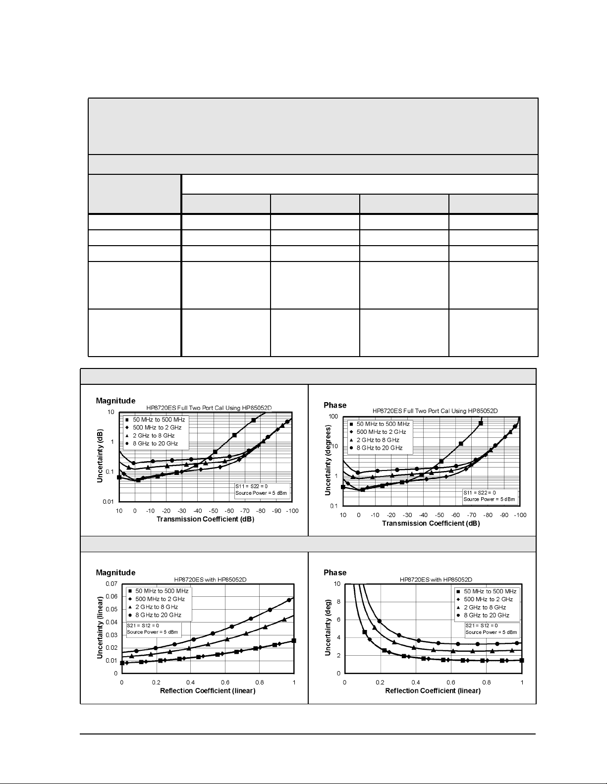
Table 1-3 3.5-mm Device Connector Type
Network Analyzer: HP 8719ES/20ES, Standard
Calibration Kit: HP 85052D (3.5-mm, 50 Ω)
Cables: HP 85131F
Calibration: Full 2-Port
IF BW = 10 Hz, Avg off, Temp = 23 ± 3°C with < 1°C deviation from cal temp, Isol cal with avg = 8
Description Specification
50 to 500 MHz 0.5 to 2 GHz 2 to 8 GHz 8 to 20 GHz
Directivity (dB) 42 42 38 36
Source Match (dB) 37 37 31 28
Load Match (dB) 42 42 38 36
Refl. Tracking
Magnitude (dB) ±(0.006 + .02/°C) ±(0.006 + .03/°C) ±(0.006 + .03/°C) ±(0.009 + .04/°C)
Phase (deg) ±(0.040 + 0.1/°C) ±(0.040 + 0.1/°C) ±(0.040 + 0.3/°C) ±(0.059 + 0.5/°C)
Trans. Tracking
Magnitude (dB) ±(0.028 + .02/°C) ±(0.03 + .03/°C) ±(0.096 + .03/°C) ±(0.158 + .04/°C)
Phase (deg) ±(0.185 + 0.1/°C) ±(0.198 + 0.1/°C) ±(0.634 + 0.3/°C) ±(1.04 + 0.5/°C)
Transmission Uncertainty (Specification)
Reflection Uncertainty (Specification)
1-5
Page 16
HP 8719/20/22ES Specifications and Characteristics
Corrected System Performance (HP 8719/20ES)
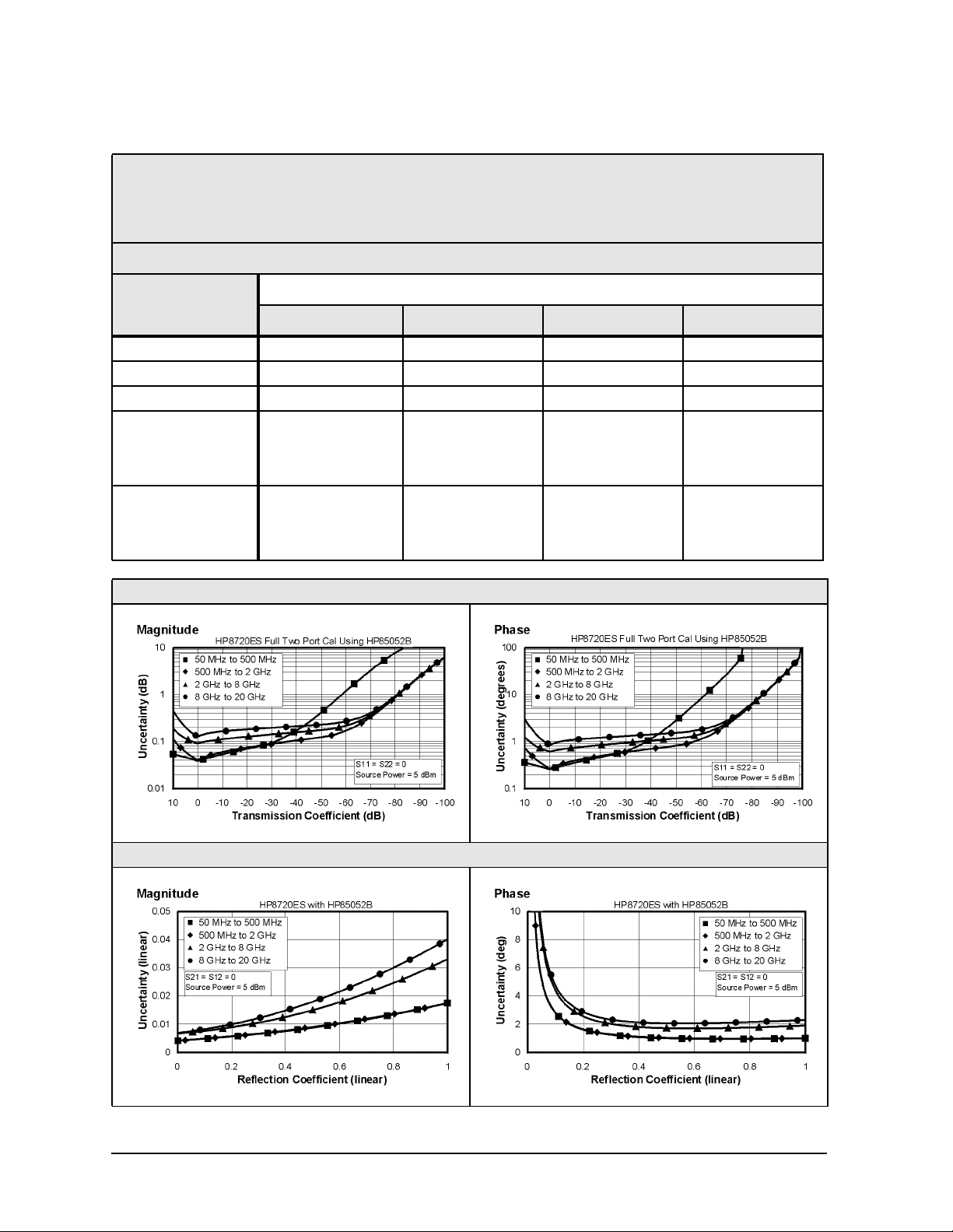
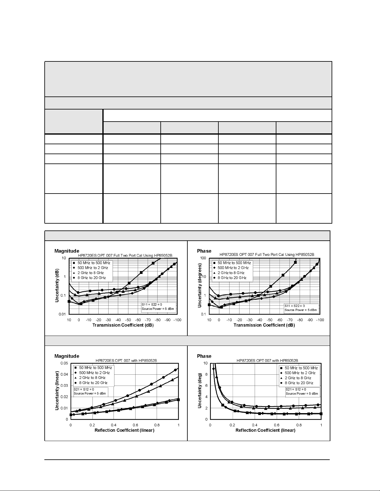
Table 1-4 3.5-mm Device Connector Type
Network Analyzer: HP 8719ES/20ES, Standard
Calibration Kit: HP 85052B (3.5-mm, 50 Ω)
Cables: HP 85131F
Calibration: Full 2-Port
IF BW = 10 Hz, Avg off, Temp = 23 ± 3°C with < 1°C deviation from cal temp, Isol cal with avg = 8
Description Specification
50 to 500 MHz 0.5 to 2 GHz 2 to 8 GHz 8 to 20 GHz
Directivity (dB) 48 48 44 44
Source Match (dB) 40 40 33 31
Load Match (dB) 48 48 44 44
Refl. Tracking
Magnitude (dB) ±(0.006 + .02/°C) ±(0.006 + .03/°C) ±(0.006 + .03/°C) ±(0.008 + .04/°C)
Phase (deg) ±(0.040 + 0.1/°C) ±(0.040 + 0.1/°C) ±(0.040 + 0.3/°C) ±(0.053 + 0.5/°C)
Trans. Tracking
Magnitude (dB) ±(0.017 + .02/°C) ±(0.018 + .03/°C) ±(0.066 + .03/°C) ±(0.099 + .04/°C)
Phase (deg) ±(0.112 + 0.1/°C) ±(0.119 + 0.1/°C) ±(0.436 + 0.3/°C) ±(0.653 + 0.5/°C)
Transmission Uncertainty (Specification)
Reflection Uncertainty (Specification)
1-6
Page 17
HP 8719/20/22ES Specifications and Characteristics
Corrected System Performance (HP 8719/20ES)
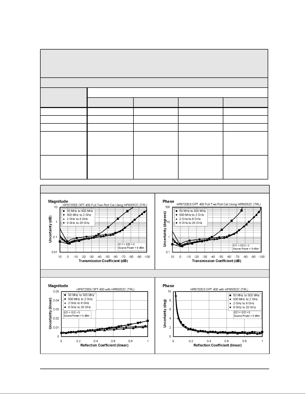
Table 1-5 3.5-mm Device Connector Type
Network Analyzer: HP 8719ES/20ES, Option 400
Calibration Kit: HP 85052C (3.5-mm, 50 Ω)
Cables: HP 85131F
Calibration: TRL
IF BW = 10 Hz, Avg off, Temp = 23 ± 3°C with < 1°C deviation from cal temp, Isol cal with avg = 8
Description Specification
50 to 500 MHz 0.5 to 2 GHz 2 to 8 GHz 8 to 20 GHz
Directivity (dB) 48 48 50 50
Source Match (dB) 40 40 50 50
Load Match (dB) 48 48 50 50
Refl. Tracking
Magnitude (dB) ±(0.006 + .02/°C) ±(0.006 + .03/°C) ±(0.005 + .03/°C) ±(0.005 + .04/°C)
Phase (deg) ±(0.040 + 0.1/°C) ±(0.040 + 0.1/°C) ±(0.033 + 0.3/°C) ±(0.033 + 0.5/°C)
Trans. Tracking
Magnitude (dB) ±(0.013 + .02/°C) ±(0.017 + .03/°C) ±(0.016 + .03/°C) ±(0.019 + .04/°C)
Phase (deg) ±(0.086 + 0.1/°C) ±(0.112 + 0.1/°C) ±(0.107 + 0.3/°C) ±(0.125 + 0.5/°C)
Transmission Uncertainty (Specification)
Reflection Uncertainty (Specification)
1-7
Page 18
HP 8719/20/22ES Specifications and Characteristics
Corrected System Performance (HP 8719/20ES)
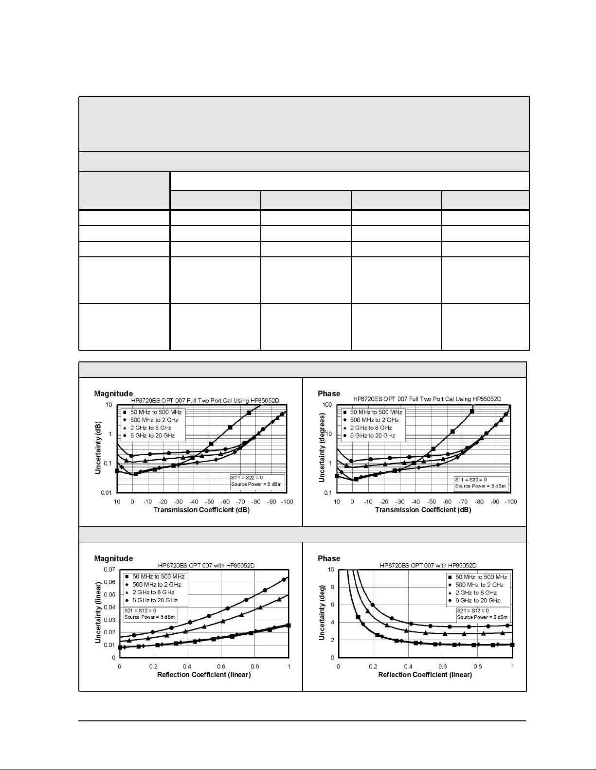
Table 1-6 3.5-mm Device Connector Type
Network Analyzer: HP 8719ES/20ES, Option 007
Calibration Kit: HP 85052B (3.5-mm with Sliding Loads, 50 Ω)
Cables: HP 85132F
Calibration: Full 2-Port
IF BW = 10 Hz, Avg off, Temp = 23 ± 3°C with < 1°C deviation from cal temp, Isol cal with avg = 8
Description Specification
0.05 to 0.5 GHz 0.5 to 2 GHz 2 t0 8GHz 8 to 20 GHz
Directivity (dB) 48 48 44 44
Source Match (dB) 40 39 32 30
Load Match (dB) 48 45 38 37
Refl. Tracking
Magnitude (dB) ±(0.006 + .02/°C) ±(0.010 + .03/°C) ±(0.030 + .03/°C) ±(0.031 + .04/°C)
Phase (deg) ±(0.040 + 0.1/°C) ±(0.066 + 0.1/°C) ±(0.198 + 0.3/°C) ±(0.205 + 0.5/°C)
Trans. Tracking
Magnitude (dB) ±(0.011 + .02/°C) ±(0.016 + .03/°C) ±(0.066 + .03/°C) ±(0.108 + .04/°C)
Phase (deg) ±(0.073 + 0.1/°C) ±(0.106 + 0.1/°C) ±(0.436 + 0.3/°C) ±(0.713 + 0.5/°C)
Transmission Uncertainty (Specification)
Reflection Uncertainty (Specification)
1-8
Page 19
HP 8719/20/22ES Specifications and Characteristics
Corrected System Performance (HP 8719/20ES)
Table 1-7 3.5-mm Device Connector Type
Network Analyzer: HP 8719ES/20ES, Option 007
Calibration Kit: HP 85052D (3.5-mm 50 Ω)
Cables: HP 85132F
Calibration: Full 2-Port
IF BW = 10 Hz, Avg off, Temp = 23 ± 3°C with < 1°C deviation from cal temp, Isol cal with avg = 8
Description Specification
0.05 to 0.5 GHz 0.5 to 2 GHz 2 t0 8GHz 8 to 20 GHz
Directivity (dB) 42 42 38 36
Source Match (dB) 37 37 30 28
Load Match (dB) 42 41 36 34
Refl. Tracking
Magnitude (dB) ±(0.006 + .02/°C) ±(0.010 + .03/°C) ±(0.030 + .03/°C) ±(0.031 + .04/°C)
Phase (deg) ±(0.038 + 0.1/°C) ±(0.069 + 0.1/°C) ±(0.200 + 0.3/°C) ±(0.205 + 0.5/°C)
Trans. Tracking
Magnitude (dB) ±(0.018 + .02/°C) ±(0.019 + .03/°C) ±(0.080 + .03/°C) ±(0.141 + .04/°C)
Phase (deg) ±(0.118 + 0.1/°C) ±(0.123 + 0.1/°C) ±(0.531 + 0.3/°C) ±(0.928 + 0.5/°C)
Transmission Uncertainty (Specification)
Reflection Uncertainty (Specification)
1-9
Page 20
HP 8719/20/22ES Specifications and Characteristics
Corrected System Performance (HP 8719/20ES)
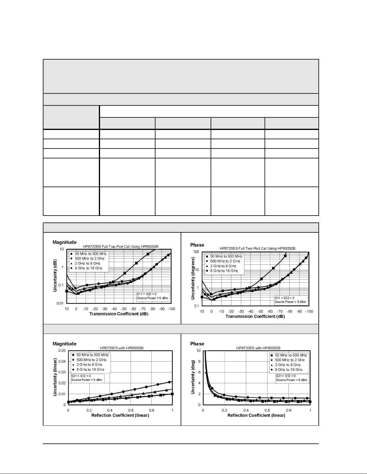
Table 1-8 7-mm Device Connector Type
Network Analyzer: HP 8719ES/20ES, Standard
Calibration Kit: HP 85050B (7-mm, 50 Ω)
Cables: HP 85132F
Calibration: Full 2-Port
IF BW = 10 Hz, Avg off, Temp = 23 ± 3°C with < 1°C deviation from cal temp, Isol cal with avg = 8
Description Specification
50 to 500 MHz 0.5 to 2 GHz 2 to 8 GHz 8 to 18 GHz
Directivity (dB) 52 52 52 52
Source Match (dB) 48 48 44 41
Load Match (dB) 51 51 51 51
Refl. Tracking
Magnitude (dB) ±(0.006 + .02/°C) ±(0.006 + .03/°C) ±(0.017 + .03/°C) ±(0.047 + .04/°C)
Phase (deg) ±(0.040 + 0.1/°C) ±(0.040 + 0.1/°C) ±(0.112 + 0.3/°C) ±(0.310 + 0.5/°C)
Trans. Tracking
Magnitude (dB) ±(0.01 + .02/°C) ±(0.011 + .03/°C) ±(0.022 + .03/°C) ±(0.034 + .04/°C)
Phase (deg) ±(0.066 + 0.1/°C) ±(0.073 + 0.1/°C) ±(0.145 + 0.3/°C) ±(0.224 + 0.5/°C)
Transmission Uncertainty (Specification)
Reflection Uncertainty (Specification)
1-10
Page 21
HP 8719/20/22ES Specifications and Characteristics
Corrected System Performance (HP 8719/20ES)
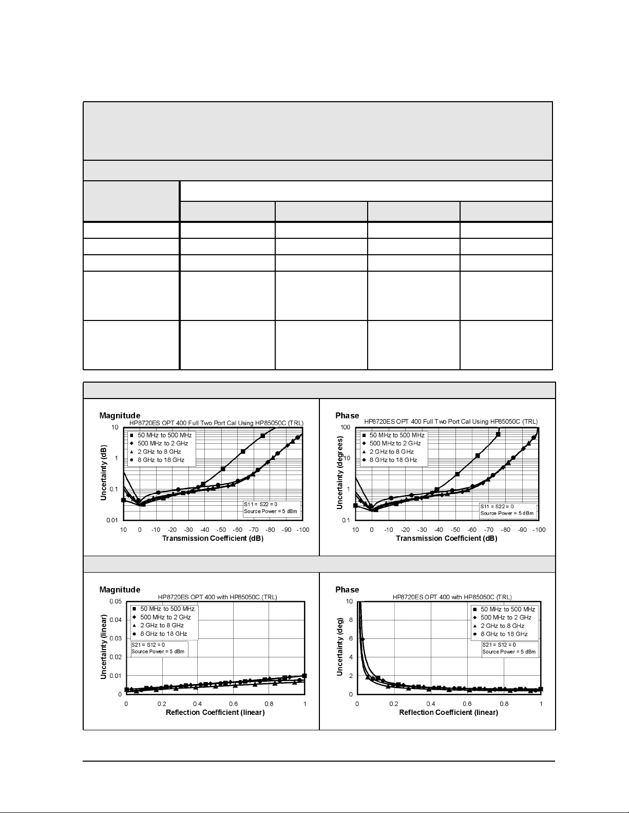
Table 1-9 7-mm Device Connector Type
Network Analyzer: HP 8719ES/20ES, Option 400
Calibration Kit: HP 85050C (7-mm, 50 Ω)
Cables: HP 85132F
Calibration: TRL
IF BW = 10 Hz, Avg off, Temp = 23 ± 3°C with < 1°C deviation from cal temp, Isol cal with avg = 8
Description Specification
50 to 500 MHz 0.5 to 2 GHz 2 to 8 GHz 8 to 18 GHz
Directivity (dB) 52 52 60 60
Source Match (dB) 48 48 57 57
Load Match (dB) 51 51 57 57
Refl. Tracking
Magnitude (dB) ±(0.006 + .02/°C) ±(0.006 + .03/°C) ±(0.005 + .03/°C) ±(0.005 + .04/°C)
Phase (deg) ±(0.040 + 0.1/°C) ±(0.040 + 0.1/°C) ±(0.033 + 0.3/°C) ±(0.33 + 0.5/°C)
Trans. Tracking
Magnitude (dB) ±(0.008 + .02/°C) ±(0.009 + .03/°C) ±(0.008 + .03/°C) ±(0.009 + .04/°C)
Phase (deg) ±(0.053 + 0.1/°C) ±(0.059 + 0.1/°C) ±(0.055 + 0.3/°C) ±(0.059 + 0.5/°C)
Transmission Uncertainty (Specification)
Reflection Uncertainty (Specification)
1-11
Page 22
HP 8719/20/22ES Specifications and Characteristics
Corrected System Performance (HP 8719/20ES)
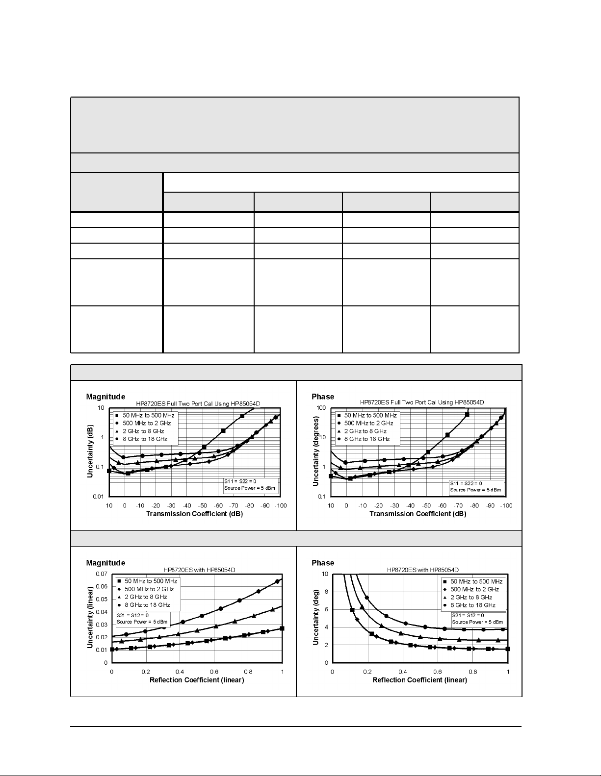
Table 1-10 Type-N Device Connector Type
Network Analyzer: HP 8719ES/20ES, Standard
Calibration Kit: HP 85054D (Type-N, 50 Ω)
Cables: HP 85132F
Calibration: Full 2-Port
IF BW = 10 Hz, Avg off, Temp = 23 ± 3°C with < 1°C deviation from cal temp, Isol cal with avg = 8
Description Specification
50 to 500 MHz 0.5 to 2 GHz 2 to 8 GHz 8 to 18 GHz
Directivity (dB) 40 40 36 34
Source Match (dB) 38 38 33 29
Load Match (dB) 40 40 36 34
Refl. Tracking
Magnitude (dB) ±(0.006 + .02/°C) ±(0.006 + .03/°C) ±(0.009 + .03/°C) ±(0.027 + .04/°C)
Phase (deg) ±(0.040 + 0.1°C) ±(0.040 + 0.1/°C) ±(0.059 + .30/°C) ±(0.178 + 0.5/°C)
Trans. Tracking
Magnitude (dB) ±(0.031 + .02/°C) ±(0.033 + .03/°C) ±(0.094 + .03/°C) ±(0.168 + .04/°C)
Phase ±(0.205 + 0.1/°C) ±(0.218 + 0.1/°C) ±(0.620 + 0.3/°C) ±(1.109 + 0.5/°C)
Transmission Uncertainty (Specification)
Reflection Uncertainty (Specification)
1-12
Page 23

HP 8719/20/22ES Specifications and Characteristics
Corrected System Performance (HP 8719/20ES)
Table 1-11 Type-N Device Connector Type
Network Analyzer: HP 8719ES/20ES, Standard
Calibration Kit: HP 85054B (Type-N, 50 Ω)
Cables: HP 85132F
Calibration: Full 2-Port
IF BW = 10 Hz, Avg off, Temp = 23 ± 3°C with < 1°C deviation from cal temp, Isol cal with avg = 8
Description Specification
50 to 500 MHz 0.5 to 2 GHz 2 to 8 GHz 8 to 18 GHz
Directivity (dB) 48 48 42 42
Source Match (dB) 45 45 36 32
Load Match (dB) 48 48 42 42
Refl. Tracking
Magnitude (dB) ±(0.005 + .02/°C) ±(0.005 + .03/°C) ±(0.006 + .03/°C) ±(0.015 + .04/°C)
Phase (deg) ±(0.033 + 0.1/°C) ±(0.033 + 0.1/°C) ±(0.040 + .30/°C) ±(0.99 + 0.50/°C)
Trans. Tracking
Magnitude (dB) ±(0.014 + .02/°C) ±(0.015 + .03/°C) ±(0.055 + .03/°C) ±(0.093 + .04/°C)
Phase(deg) ±(0.092 + 0.1/°C) ±(0.099 + 0.1/°C) ±(0.363 + .30/°C) ±(0.614 + .50/°C)
Transmission Uncertainty (Specification)
Reflection Uncertainty (Specification)
1-13
Page 24

HP 8719/20/22ES Specifications and Characteristics
Corrected System Performance (HP 8722ES)
Corrected System Performance (HP 8722ES)
The specifications in this section apply for measurements made using 10 Hz IF bandwidth,
no averaging, and at an environmental temperature of 23 ±3 °C, with less than 1 °C
deviation from the calibration temperature. Assumes that an isolation calibration was
performed with an averaging factor of 8.
1-14
Page 25
HP 8719/20/22ES Specifications and Characteristics
Corrected System Performance (HP 8722ES)
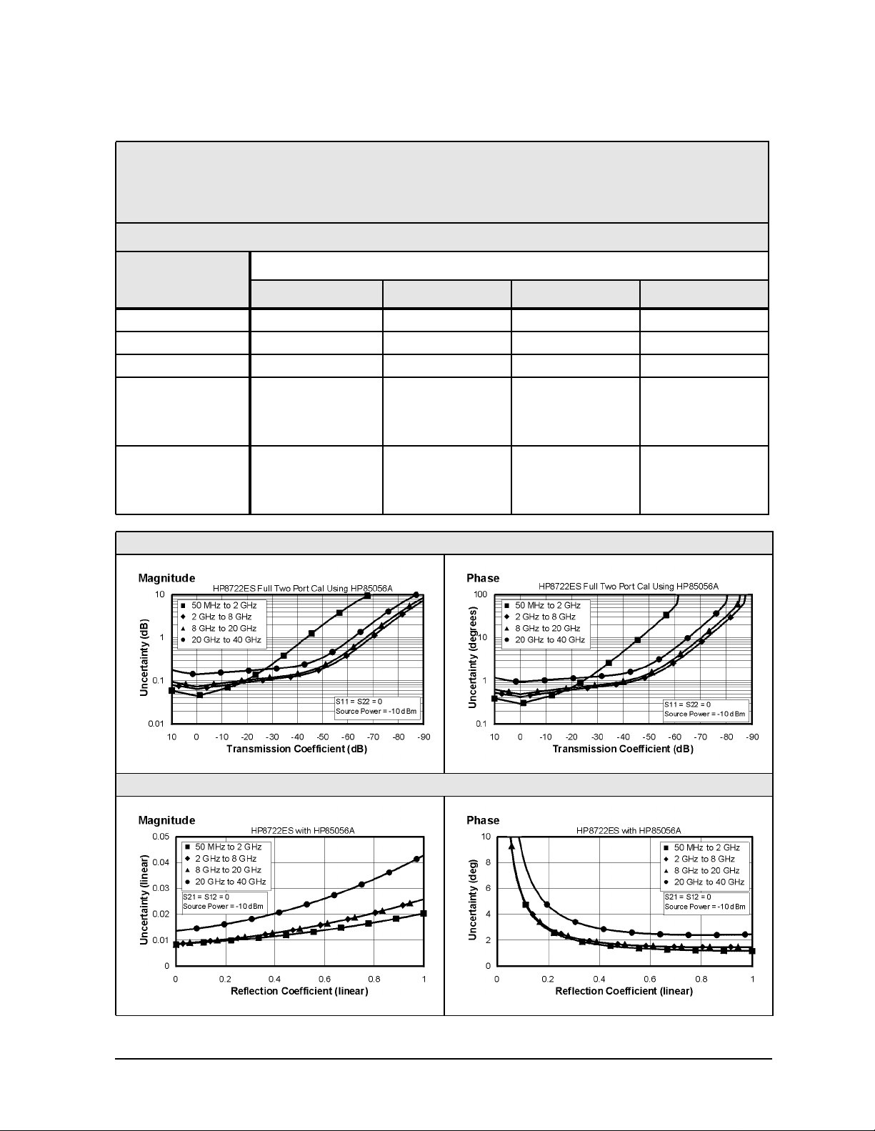
Table 1-12 2.4-mm Device Connector Type
Network Analyzer: HP 8722ES, Standard
Calibration Kit: HP 85056A (2.4-mm, 50 Ω)
Cables: HP 85133F
Calibration: Full 2-Port
IF BW = 10 Hz, Avg off, Temp = 23 ± 3°C with < 1°C deviation from cal temp, Isol cal with avg = 8
Description Specification
0.05 to 2 GHz 2 to 8 GHz 8 to 20 GHz 20 to 40 GHz
Directivity (dB) 42 42 42 38
Source Match (dB) 41 38 38 33
Load Match (dB) 42 42 42 38
Refl. Tracking
Magnitude (dB) ±(0.005 + .03/°C) ±(0.010 + .03/°C) ±(0.010 + .04/°C) ±(0.021 + .06/°C)
Phase (deg) ±(0.033 + 0.1/°C) ±(0.066 + 0.3/°C) ±(0.066 + 0.5/°C) ±(0.139 + 1.0/°C)
Trans. Tracking
Magnitude (dB) ±(0.020 + .03/°C) ±(0.038 + .03/°C) ±(0.048 + .04/°C) ±(0.110 + .06/°C)
Phase (deg) ±(0.132 + 0.1/°C) ±(0.251 + 0.3/°C) ±(0.317 + 0.5/°C) ±(0.736 + 1.0/°C)
Transmission Uncertainty (Specification)
Reflection Uncertainty (Specification)
1-15
Page 26
HP 8719/20/22ES Specifications and Characteristics
Corrected System Performance (HP 8722ES)
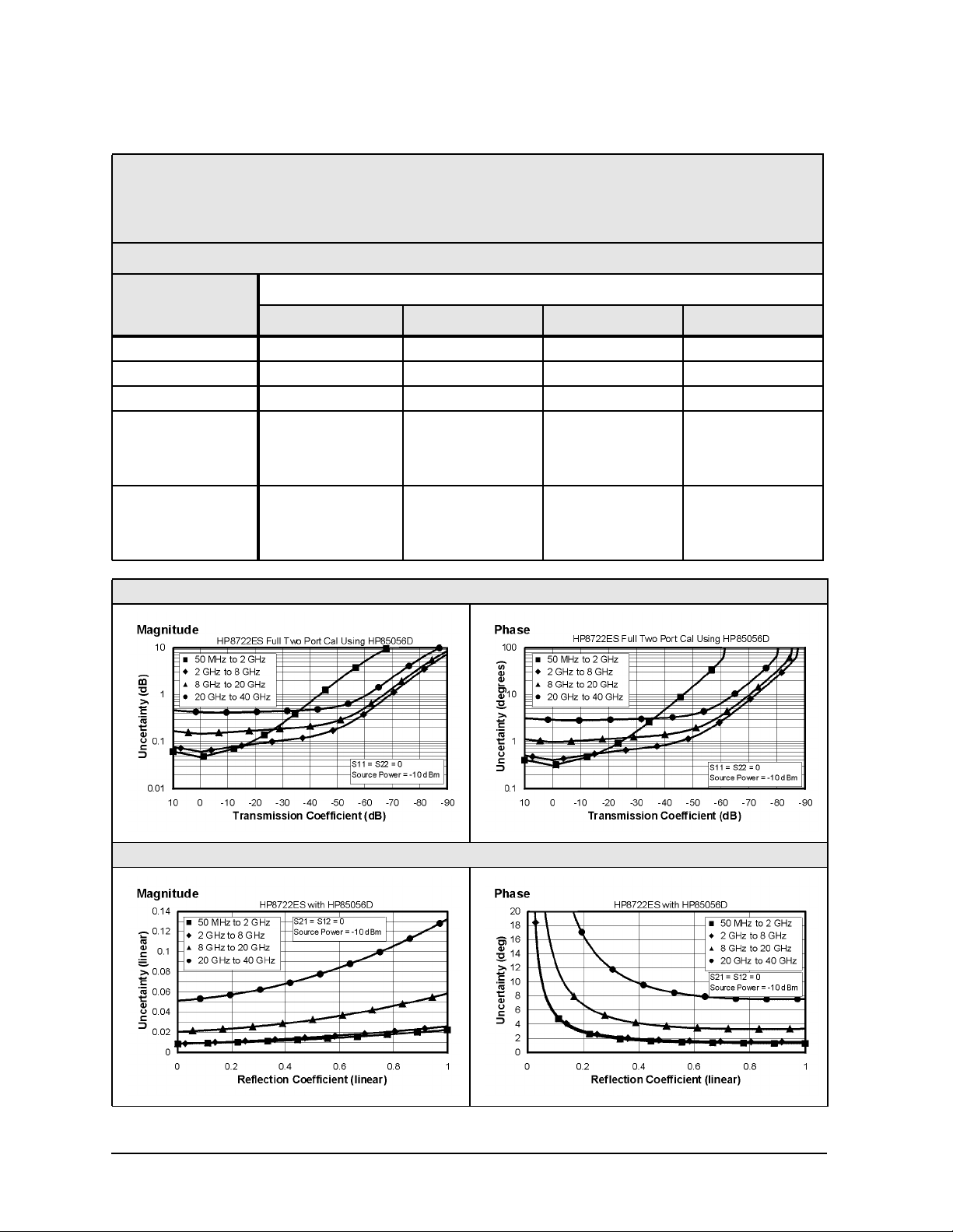
Table 1-13 2.4-mm Device Connector Type
Network Analyzer: HP 8722ES, Standard
Calibration Kit: HP 85056D (2.4-mm, 50 Ω)
Cables: HP 85133F
Calibration: Full 2-Port
IF BW = 10 Hz, Avg off, Temp = 23 ± 3°C with < 1°C deviation from cal temp, Isol cal with avg = 8
Description Specification
0.05 to 2 GHz 2 to 8 GHz 8 to 20 GHz 20 to 40 GHz
Directivity (dB) 42 42 34 26
Source Match (dB) 40 40 30 23
Load Match (dB) 42 42 34 26
Refl. Tracking
Magnitude (dB) ±(0.006 + .03/°C) ±(0.029 + .03/°C) ±(0.029 + .04/°C) ±(0.080 + .06/°C)
Phase (deg) ±(0.040 + 0.1/°C) ±(0.191 + 0.3/°C) ±(0.191 + 0.5/°C) ±(0.528 + 1.0/°C)
Trans. Tracking
Magnitude (dB) ±(0.022 + .03/°C) ±(0.034 + .03/°C) ±(0.116 + .04/°C) ±(0.372 + .06/°C)
Phase (deg) ±(0.145 + 0.1/°C) ±(0.224 + 0.3/°C) ±(0.766 + 0.5/°C) ±(2.455 + 1.0/°C)
Transmission Uncertainty (Specification)
Reflection Uncertainty (Specification)
1-16
Page 27
HP 8719/20/22ES Specifications and Characteristics
Corrected System Performance (HP 8722ES)
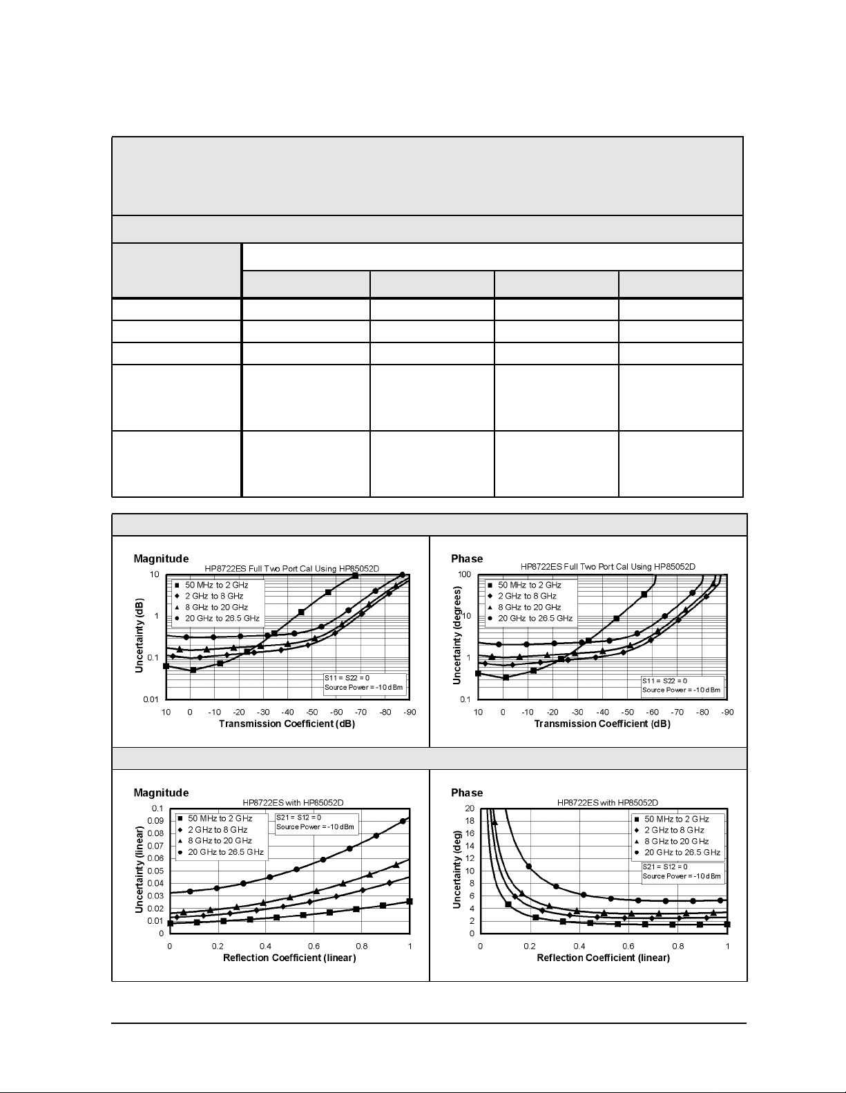
Table 1-14 3.5-mm Device Connector Type
Network Analyzer: HP 8722ES, Standard
Calibration Kit: HP 85052D (3.5-mm, 50 Ω)
Cables: HP 85131F
Calibration: Full 2-Port
IF BW = 10 Hz, Avg off, Temp = 23 ± 3°C with < 1°C deviation from cal temp, Isol cal with avg = 8
Description Specification
0.05 to 2 GHz 2 to 8 GHz 8 to 20 GHz 20 to 26.5 GHz
Directivity (dB) 42 38 36 30
Source Match (dB) 37 31 28 25
Load Match (dB) 42 38 36 30
Refl. Tracking
Magnitude (dB) ±(0.006 + .03/°C) ±(0.006 + .03/°C) ±(0.009 + .04/°C) ±(0.012 + .06/°C)
Phase (deg) ±(0.040 + 0.1/°C) ±(0.040 + 0.30/°C) ±(0.059 + 0.5/°C) ±(0.079 + 1.0/°C)
Trans. Tracking
Magnitude (dB) ±(0.026 + .03/°C) ±(0.071 + .03/°C) ±(0.121 + .04/°C) ±(0.266 + .06/°C)
Phase(deg) ±(0.172 + 0.1/°C) ±(0.469 + 0.3/°C) ±(0.792 + 0.5/°C) ±(1.782 + 1.0/°C)
Transmission Uncertainty (Specification)
Reflection Uncertainty (Specification)
1-17
Page 28
HP 8719/20/22ES Specifications and Characteristics
Corrected System Performance (HP 8722ES)
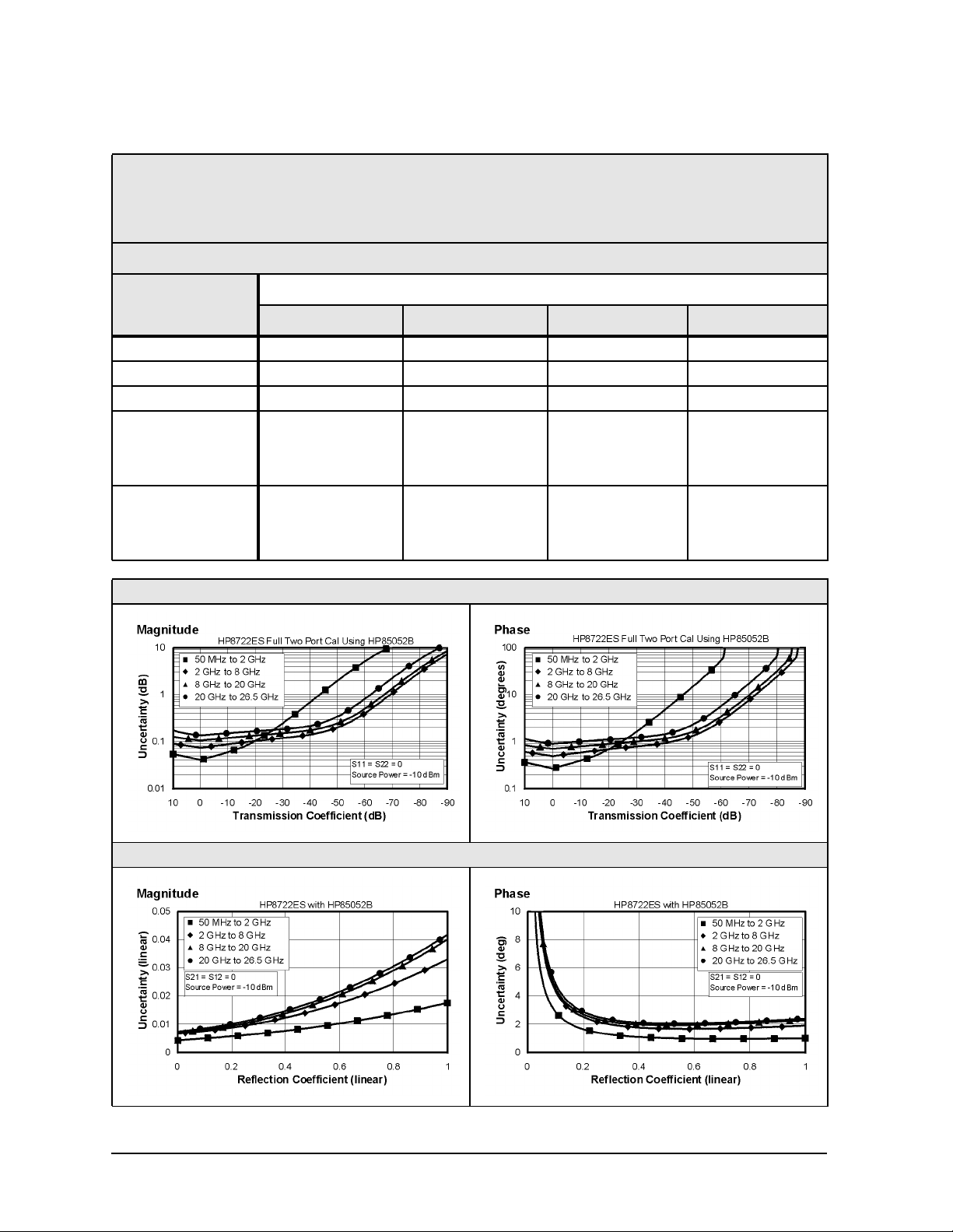
Table 1-15 3.5-mm Device Connector Type
Network Analyzer: HP 8722ES, Standard
Calibration Kit: HP 85052B (3.5-mm, 50 Ω)
Cables: HP 85131F
Calibration: Full 2-Port
IF BW = 10 Hz, Avg off, Temp = 23 ± 3°C with < 1°C deviation from cal temp, Isol cal with avg = 8
Description Specification
0.05 to 2 GHz 2 to 8 GHz 8 to 20 GHz 20 to 26.5 GHz
Directivity (dB) 48 44 44 44
Source Match (dB) 40 33 31 31
Load Match (dB) 48 44 44 44
Refl. Tracking
Magnitude (dB) ±(0.006 + .03/°C) ±(0.006 + .03/°C) ±(0.008 + .04/°C) ±(0.008 + .06/°C)
Phase (deg) ±(0.040 + 0.1/°C) ±(0.040 + 0.3/°C) ±(0.053 + 0.5/°C) ±(0.053 + 1.0/°C)
Trans. Tracking
Magnitude (dB) ±(0.017 + .03/°C) ±(0.049 + .03/°C) ±(0.077 + .04/°C) ±(0.102 + .06/°C)
Phase (deg) ±(0.112 + 0.1/°C) ±(0.323 + 0.3/°C) ±(0.508 + 0.5/°C) ±(0.673 + 1.0/°C)
Transmission Uncertainty (Specification)
Reflection Uncertainty (Specification)
1-18
Page 29
HP 8719/20/22ES Specifications and Characteristics
Corrected System Performance (HP 8722ES)
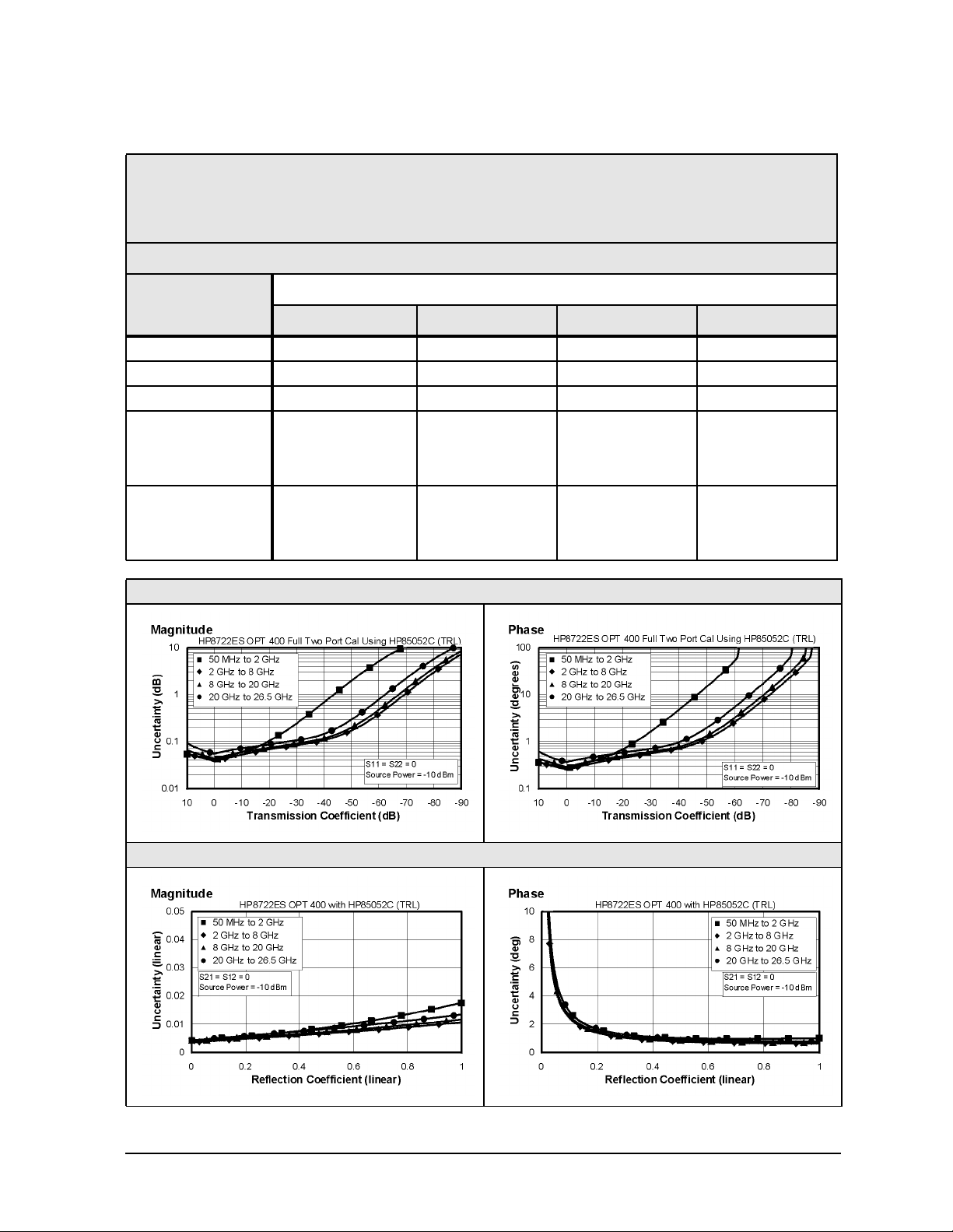
Table 1-16 3.5-mm Device Connector Type
Network Analyzer: HP 8722ES, Option 400
Calibration Kit: HP 85052C (3.5-mm, 50 Ω)
Cables: HP 85131F
Calibration: TRL
IF BW = 10 Hz, Avg off, Temp = 23 ± 3 °C with < 1 °C deviation from cal temp, Isol cal with avg = 8
Description Specification
0.05 to 2 GHz 2 to 8 GHz 8 to 20 GHz 20 to 26.5 GHz
Directivity (dB) 48 50 50 50
Source Match (dB) 40 50 50 50
Load Match (dB) 48 50 50 50
Refl. Tracking
Magnitude (dB) ±(0.006 + .03/°C) ±(0.005 + .03/°C) ±(0.005 + .04/°C) ±(0.005 + .06/°C)
Phase (deg) ±(0.040 + 0.1/°C) ±(0.033 + 0.3/°C) ±(0.033 + 0.5/°C) ±(0.033 + 1.0/°C)
Trans. Tracking
Magnitude (dB) ±(0.017 + .03/°C) ±(0.013 + .03/°C) ±(0.016 + .04/°C) ±(0.023 + .06/°C)
Phase(deg) ±(0.112 + 0.1/°C) ±(0.086 + 0.3/°C) ±(0.106 + 0.5/°C) ±(0.152 + 1.0/°C)
Transmission Uncertainty (Specification)
Reflection Uncertainty (Specification)
1-19
Page 30
HP 8719/20/22ES Specifications and Characteristics
Corrected System Performance (HP 8722ES)
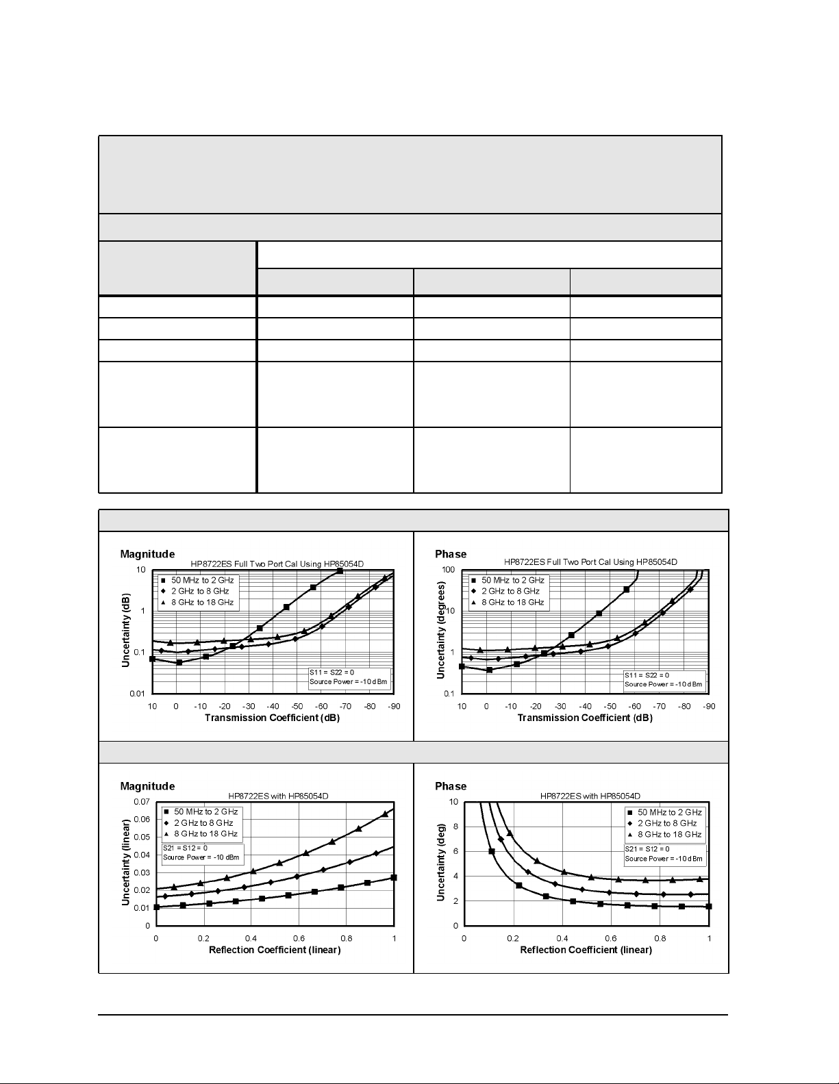
Table 1-17 Type-N Device Connector Type
Network Analyzer: HP 8722ES, Standard
Calibration Kit: HP 85054D (Type-N, 50 Ω)
Cables: HP 85132F
Calibration: Full 2-Port
IF BW = 10 Hz, Avg off, Temp = 23 ± 3 °C with < 1 °C deviation from cal temp, Isol cal with avg = 8
Description Specification
0.05 to 2 GHz 2 to 8 GHz 8 to 18 GHz
Directivity (dB) 40 36 34
Source Match (dB) 38 33 29
Load Match (dB) 40 36 34
Refl. Tracking
Magnitude (dB) ±(0.006 + .03/°C) ±(0.009 + .03/°C) ±(0.027 + .04/°C)
Phase (deg) ±(0.040 + 0.1/°C) ±(0.059 + 0.3/°C) ±(0.178 + 0.5/°C)
Trans. Tracking
Magnitude (dB) ±(0.026 + .03/°C) ±(0.070 + .03/°C) ±(0.128 + .04/°C)
Phase(deg) ±(0.172 + 0.1/°C) ±(0.462 + 0.3/°C) ±(0.845 + 0.5/°C)
Transmission Uncertainty (Specification)
Reflection Uncertainty (Specification)
1-20
Page 31

HP 8719/20/22ES Specifications and Characteristics
Corrected System Performance (HP 8722ES)
Table 1-18 2.4-mm Device Connector Type
Network Analyzer: HP 8722ES, Option 007
Calibration Kit: HP 85056A (2.4-mm with sliding loads, 50 Ω)
Cables: HP 85133F
Calibration: Full 2-Port
IF BW = 10 Hz, Avg off, Temp = 23 ± 3 °C with < 1 °C deviation from cal temp, Isol cal with avg = 8
Description Specification
0.05 to 2 GHz 2 to 8 GHz 8 to 20 GHz 20 to 40 GHz
Directivity (dB) 42 42 42 38
Source Match (dB) 40 35 34 31
Load Match (dB) 41 38 37 35
Refl. Tracking
Magnitude (dB) ±(0.011 + .03/°C) ±(0.037 + .03/°C) ±(0.039 + .04/°C) ±(0.047 + .06/°C)
Phase (deg) ±(0.007 + 0.1/°C) ±(0.007 + 0.3/°C) ±(0.035 + 0.5/°C) ±(0.140 + 1.0/°C)
Trans. Tracking
Magnitude (dB) ±(0.021 + .03/°C) ±(0.054 + .03/°C) ±(0.085 + .04/°C) ±(0.149 + .06/°C)
Phase (deg) ±(0.139 + 0.1/°C) ±(0.042 + 0.3/°C) ±(0.561 + 0.5/°C) ±(0.983 + 1.0/°C)
Transmission Uncertainty (Specification)
Reflection Uncertainty (Specification)
1-21
Page 32

HP 8719/20/22ES Specifications and Characteristics
Corrected System Performance (HP 8722ES)
Table 1-19 2.4-mm Device Connector Type
Network Analyzer: HP 8722ES, Option 007
Calibration Kit: HP 85056D (2.4-mm 50 Ω)
Cables: HP 85133F
Calibration: Full 2-Port
IF BW = 10 Hz, Avg off, Temp = 23 ± 3 °C with < 1 °C deviation from cal temp, Isol cal with avg = 8
Description Specification
0.05 to 2 GHz 2 to 8 GHz 8 to 20 GHz 20 to 40 GHz
Directivity (dB) 42 42 34 26
Source Match (dB) 39 35 29 23
Load Match (dB) 41 38 33 26
Refl. Tracking
Magnitude (dB) ±(0.011 + .03/°C) ±(0.046 + .03/°C) ±(0.048 + .04/°C) ±(0.090 + .06/°C)
Phase (deg) ±(0.074 + 0.1/°C) ±(0.303 + 0.3/°C) ±(0.314 + 0.5/°C) ±(0.593 + 1.0/°C)
Trans. Tracking
Magnitude (dB) ±(0.021 + .03/°C) ±(0.054 + .03/°C) ±(0.130 + .04/°C) ±(0.367 + .06/°C)
Phase (deg) ±(0.147 + 0.1/°C) ±(0.351 + 0.3/°C) ±(0.860 + 0.5/°C) ±(2.420 + 1.0/°C)
Transmission Uncertainty (Specification)
Reflection Uncertainty (Specification)
1-22
Page 33

HP 8719/20/22ES Specifications and Characteristics
Corrected System Performance (HP 8722ES)
Table 1-20 Type-N Device Connector Type
Network Analyzer: HP 8722ES, Standard
Calibration Kit: HP 85054B (Type-N, 50 Ω)
Cables: HP 85132F
Calibration: Full 2-Port
IF BW = 10 Hz, Avg off, Temp = 23 ± 3 °C with < 1 °C deviation from cal temp, Isol cal with avg = 8
Description Specification
0.05 to 2 GHz 2 to 8 GHz 8 to 18 GHz
Directivity (dB) 48 42 42
Source Match (dB) 46 36 33
Load Match (dB) 48 42 42
Refl. Tracking
Magnitude (dB) ±(0.005 + .03/°C) ±(0.006 + .03/°C) ±(0.015 + .04/°C)
Phase (deg) ±(0.033 + 0.1/°C) ±(0.040 + 0.3/°C) ±(0.099 + 0.5/°C)
Trans. Tracking
Magnitude (dB) ±(0.013 + .03/°C) ±(0.041 + .03/°C) ±(0.071 + .04/°C)
Phase (deg) ±(0.086 + 0.1/°C) ±(0.271 + 0.3/°C) ±(0.469 + 0.5/°C)
Transmission Uncertainty (Specification)
Reflection Uncertainty (Specification)
1-23
Page 34

HP 8719/20/22ES Specifications and Characteristics
Instrument Specifications
Instrument Specifications
Uncorrected Port Performance
Table 1-21 3.5-mm Device Connector Type
HP 8719ES/20ES (3.5-mm, 50 Ω)
Description
50 to 500 MHz 0.5 to 2 GHz 2 to 8 GHz 8 to 20 GHz
Directivity
Source Match
Standard (dB) 12 12 10 8
Option 400 (dB) 20 20 11 10
Option 007 (dB) 16 20 14 11
Option 085 (dB) 16 18 14 8
Load Match
Standard (dB) 22 20 12 10
Option 400 (dB) 20 17 12 10
Option 007 (dB) 26 24 15 12
Option 085 (dB) 26 24 15 10
Reflection Trackingb (dB)
Transmission
Trackingb (dB)
Tracking Stability
(Ratio Measurement)
Magnitude (dB) 0.02/°C, typ. 0.03/°C, typ. 0.03/°C, typ. 0.04/°C, typ.
Phase (dB) 0.1/°C, typ. 0.1/°C, typ. 0.3/°C, typ. 0.50/°C, typ.
Crosstalkc (dB)
a
a
a
24 27 21 16
±3 ±3 ±3 ±3
±3 ±3 ±3 ±3
d
75
Characteristic
95 91 86
a. Does not include the effect of the cable set on the test ports.
b. Excludes rolloff below 500 MHz, which is typically −18 dB at 100 MHz, and −25 dB at
50 MHz.
c. Measurement conditions: Normalized to a thru, measured with two shorts, 10 Hz IF
bandwidth, averaging factor of 8, alternate mode, source power set to the lesser of the
maximum power out or the maximum receiver power.
d. Limited by noise floor.
1-24
Page 35

HP 8719/20/22ES Specifications and Characteristics
Table 1-22 2.4-mm Device Connector Type
HP 8722ES (2.4-mm, 50 Ω)
Description Characteristic
Instrument Specifications
Directivity
a
Source Match
50 to
500 MHz
23 23 21 16 15
a
0.5 to
2 GHz
2 to
8 GHz
8 to
20 GHz
20 to
40 GHz
Standard/
Option 400 (dB) 17 17 12 11 7
Option 007 or
Option 085 (dB) 17 17 15 11 8
Load Match
Standard/
a
18 18 15 12 10
Option 400 (dB)
Option 007 or
21 21 17 13 10
Option 085 (dB)
Reflection
±3 ±3 ±3 ±3 ±6
Trackingb (dB)
Transmission
Tracking
b
±3 ±3 ±3 ±3 ±6
Tracking Stability
(Ratio
Measurement)
Magnitude (dB) 0.02/°C, typ. 0.03/°C, typ. 0.03/°C, typ. .04 dB/˚C, typ. .06 dB/˚C, typ.
Phase (dB) 0.1/°C, typ. 0.1/°C, typ. 0.3/°C, typ. 0.5 ˚/˚C, typ. 1.0 ˚/˚C, typ.
Crosstalk
c
60
d
85 85 82 72
a. Does not include the effect of the cable set on the test ports.
b. Excludes rolloff below 500 MHz, which is typically −18 dB at 100 MHz, and −25 dB at
50 MHz.
c. Measurement conditions: Normalized to a thru, measured with two shorts, 10 Hz IF
bandwidth, averaging factor of 8, alternate mode, source power set to the lesser of the
maximum power out or the maximum receiver power.
d. Limited by noise floor.
1-25
Page 36

HP 8719/20/22ES Specifications and Characteristics
Instrument Specifications
Test Port Output
Table 1-23 Test Port Output
HP 8719ES/20ES/22ES Test Port Output
Description Specification Supplemental Information
Frequency
Range
HP 8719ES 0.05 to 13.51 GHz
HP 8720ES 0.05 to 20.05 GHz
HP 8722ES 0.05 to 40.05 GHz
Resolution 1 Hz
Stability
Standard ±7.5 ppm, 0˚ to 55˚C, typ.
±3 ppm/year, typ.
Option 1D5 ±0.05 ppm, 0˚ to 55˚C, typ.
±0.5 ppm/year, typ.
CW Accuracy ±10 ppm at 23˚ ±3˚C
Output Power
Level Accuracy
HP 8719ES/20ES
Standard ±2 dB at 0 dBm
Option 007 ±2 dB at +5 dBm
HP 8722ES
Standard ±3 dB at −10 dBm
Option 007 ±3 dB at −5 dBm
a
a. Absolute power accuracy at a given power level. Includes absolute accuracy and relative
flatness across frequency.
1-26
Page 37

HP 8719/20/22ES Specifications and Characteristics
Instrument Specifications
Table 1-24 Test Port Output
HP 8719ES/20ES/22ES Test Port Output
Description Specification Supplemental Information
Output Power
Maximum Leveled Power
HP 8719/20ES (Standard) +5 dBm, char.
HP 8719ES/20ES (Option 007) +10 dBm, char.
HP 8722ES (Standard)
0.05 to 20 GHz −5 dBm, char.
20 to 40 GHz −10 dBm, char.
HP 8722ES (Option 007)
0.05 to 20 GHz 0 dBm, char.
20 to 40 GHz −5 dBm, char.
Power Range
b
HP 8719/20ES (Standard) −70 to +5 dBm
HP 8719/20ES (Option 007) −65 to +10 dBm
HP 8722ES
(Standard, Options 085, 400)
0.05 to 13.5 GHz −75 to −5 dBm
13.5 to 20 GHz −75 to −5 dBm
20 to 40 GHz −75 to −10 dBm
HP 8722ES (Option 007)
0.05 to 20 GHz −70 to 0 dBm
20 to 40 GHz −70 to −5 dBm
Power Sweep Range
HP 8719/20ES 20 dB 30 dB, typ.
HP 8722ES
0.05 to 20 GHz 15 dB 25 dB, typ.
20 to 40 GHz 10 dB 20 dB, typ.
a
a. At any given frequency, the achievable power while remaining leveled. Applies to CW
mode only.
b. Power to which the source can be set and phase lock is assured.
1-27
Page 38

HP 8719/20/22ES Specifications and Characteristics
Instrument Specifications
Table 1-25 Test Port Output
HP 8719ES/20ES Test Port Output
Description Specification Supplemental Information
Output Power
Power Resolution 0.01 dB
Attenuator Switch Points:
Note: For Option 400, the switch point between Range 0 and Range 1 is −10 dBm.
1-28
Page 39

HP 8719/20/22ES Specifications and Characteristics
Instrument Specifications
Table 1-26 Test Port Output
HP 8722ES Test Port Output
Description Specification Supplemental Information
Output Power
Power Resolution 0.01 dB
Attenuator Switch Points:
Note: For Option 400, the switch point between Range 0 and Range 1 is 0 dBm.
1-29
Page 40

HP 8719/20/22ES Specifications and Characteristics
Instrument Specifications
Table 1-27 Test Port Output
HP 8719ES/20ES Test Port Output
Description Specification Supplemental Information
Linearity
a
−5 dB from reference ±0.35 dB
+5 dB from reference ±0.35 dB
−10 dB from reference ±0.6 dB
+10 dB from reference ±1.0 dB
Impedance
Standard 50 Ω, nominal
Attenuator Accuracy
b
0 dB reference; at 50 MHz
5 dB ±0.6 dB, char.
10 dB ±0.9 dB, char.
15 dB ±1.25 dB, char.
20 dB ±1.5dB, char.
25 dB ±2.0 dB, char.
30 dB ±2.5 dB, char.
35 dB ±2.8 dB, char.
40 dB ±3.0 dB, char.
45 dB ±3.1 dB, char.
50 dB ±3.2 dB, char.
55 dB ±3.2 dB, char.
Test Reference Powers:
Standard HP 8719/20ES: −5 dBm
HP 8719/20ES Option 007: 0 dBm
a. Change in source output power for a given change in source power setting at any given
frequency.
b. The accuracy, relative to the 0 dB setting, of each setting of an attenuator, at a given
frequency.
1-30
Page 41

HP 8719/20/22ES Specifications and Characteristics
Instrument Specifications
Table 1-28 Test Port Output
HP 8722ES Test Port Output
Description Specification Supplemental Information
Linearity
a
−5 dB from reference
50 MHz to 20 GHz ±0.35 dB
20 GHz to 40 GHz ±0.6 dB
+5 dB from reference
50 MHz to 20 GHz ±0.35 dB
−10 dB from reference ±0.6 dB
Impedance
Standard 50 Ω, nominal
Attenuator Accuracy
b
0 dB reference; at 50 MHz
5 dB ±0.5 dB, char.
10 dB ±0.5 dB, char.
15 dB ±0.6 dB, char.
20 dB ±0.6 dB, char.
25 dB ±0.7 dB, char.
30 dB ±0.7 dB, char.
35 dB ±1.0 dB, char.
40 dB ±1.0 dB, char.
45 dB ±1.2 dB, char.
50 dB ±1.2 dB, char.
55 dB ±1.6 dB, char.
Test Reference Powers:
Standard HP 8722ES: −10 dBm
HP 8722ES Option 007: −5 dBm
a. Change in source output power for a given change in source power setting at any given
frequency.
b. The accuracy, relative to the 0 dB setting, of each setting of an attenuator, at a given
frequency.
1-31
Page 42

HP 8719/20/22ES Specifications and Characteristics
Instrument Specifications
Table 1-29 Test Port Output
HP 8719ES/20ES/22ES Test Port Output
Description Specification Supplemental Information
Signal Purity
2nd Harmonic 0.05 GHz to one half the maximum
source frequency
at the maximum output level < −15 dBc, typ.
Non-harmonic Spurious
Mixer Related
at 100 kHz offset < −40 dBc, typ.
at 200 kHz offset < −45 dBc, typ.
at > 200 kHz offset < −65 dBc, typ.
Phase Noise
60 kHz from carrier
at 2 GHz
60 kHz from carrier
at 20 GHz
< −55 dBc, typ.
< −35 dBc, typ.
1-32
Page 43

HP 8719/20/22ES Specifications and Characteristics
Instrument Specifications
Test Port Input
Table 1-30 Test Port Input
HP 8719ES/20ES/22ES Test Port Input
Description Specification Supplemental Information
Frequency Range
HP 8719ES 0.05 to 13.51 GHz
HP 8720ES 0.05 to 20.05 GHz
HP 8722ES 0.05 to 40.05 GHz
Frequency Response (A, B, R)
Channel R
0.05 to 20.05 GHz ±1.5 dB, char.
20.05 to 32 GHz ±2.5 dB, char.
32 to 40 GHz +2.5 dB to −6 dB, char.
Channels A and B
50 to 500 MHz +2.5 dB to −28 dB, char.
0.5 to 20 GHz ±2.5 dB, char.
20 to 32 GHz ±3 dB, char.
32 to 40 GHz +3 dB to −6 dB, char.
Impedance
Standard 50 Ω, nominal.
Return Loss
Standard See uncorrected load match
chart.
Maximum Input Level
Standard +10 dBm
Compression See dynamic accuracy chart.
Damage Level
Standard +30 dBm or > 40 Vdc, typ.
Option 012
test port +30 dBm or > 40 Vdc, typ.
direct sampler access +26 dBm or > 0 Vdc, typ.
a
a. Maximum level at which no test port overload messages are seen.
1-33
Page 44

HP 8719/20/22ES Specifications and Characteristics
Instrument Specifications
Table 1-31 Test Port Input
HP 8719ES/20ES/22ES Test Port Input
Description Specification Supplemental Information
0.1 dB Compression (Option 012), direct receiver input
0.05 to 0.5 GHz −5 dBm, typ.
0.5 to 2 GHz −5 dBm, typ.
2 to 8 GHz −5 dBm, typ.
8 to 20 GHz −5 dBm, typ.
20 to 40 GHz −5 dBm, typ.
Average Noise Floor (Option 012) - 10 Hz IF BWa, direct receiver input
0.05 to 0.5 GHz −120 dBm, typ.
0.5 to 2 GHz −120 dBm, typ.
2 to 8 GHz −120 dBm, typ.
8 to 20 GHz −118 dBm, typ.
20 to 40 GHz −113 dBm, typ.
Frequency Offset Operation (Option 089)
Frequency Range 50 MHz to maximum frequency
Reference (R) Input Level
Maximum
HP 8719ES/20ES −7 dBm, typ.
HP 8722ES −12 dBm, typ.
Minimum
HP 8719ES/20ES/22ES −34 dBm, typ.
LO Spectral Purity and
Accuracy
Maximum Spurious Input < −25 dBc, typ.
Residual FM < 20 kHz, typ.
Frequency Accuracy ±16 MHz, typ.
b
a. The receiver noise floor is specified as the mean of the linear magnitude noise floor trace
over the specified frequency band.
b. The RF source characteristics in this mode are dependent on the stability of the external
LO source. The RF source tracks the LO to maintain a stable IF signal at the R channel
receiver input.
1-34
Page 45

HP 8719/20/22ES Specifications and Characteristics
Instrument Specifications
Table 1-32 Test Port Input
HP 8719/20/22ES Test Port Input
Description Supplemental Information
System Bandwidths
3000 Hz 10 Hz
Trace Noise
Magnitude
0.05 GHz to 13.5 GHz < 0.03 dB rms, typ. < 0.003 dB rms, typ.
13.5 GHz to 20 GHz < 0.04 dB rms, typ. < 0.004 dB rms, typ.
20 GHz to 40 GHz < 0.15 dB rms, typ. < 0.015 dB rms, typ.
Phase
0.05 GHz to 13.5 GHz < 0.3° rms, typ. < 0.03° rms, typ.
13.5 GHz to 20 GHz < 0.4° rms, typ. < 0.04° rms, typ.
20 GHz to 40 GHz < 1.5° rms, typ. < 0.15° rms, typ.
a
a. Trace noise is defined for a transmission measurement in CW mode, using a
“through” cable having 0 dB loss, with the source set to the lesser of the
maximum source output or to the maximum receiver input, and no
averaging. Trace noise is defined as the variation of a high level trace due to
noise.
Table 1-33 Test Port Input
HP 8719/20/22ES Test Port Input
Description Specification Supplemental
Information
Reference Level
Magnitude
Range ±500 dB
Resolution 0.001 dB
Phase
Range ±500°
Resolution 0.01°
1-35
Page 46

HP 8719/20/22ES Specifications and Characteristics
Instrument Specifications
Table 1-34 Test Port Input
HP 8719/20ES Test Port Input
Dynamic Accuracy (Characteristic)
For input ports 1 and 2, accuracy of the test port input power reading relative to the reference
input power level.
• Inputs: testport 1 and 2
• For test port powers > −50 dBm and < 0 dBm, magnitude dynamic accuracy is
0.02 dB + 0.0015 dB/dB from the reference power, phase dynamic accuracy is
0.132 deg + 0.0066 deg/dB from the reference power. For test port powers > −80 dBm and
< −50 dBm, magnitude dynamic range is .02 dB + .003 dB/dB from the reference power.
• For test port powers up to maximum source power.
1-36
Page 47

Table 1-34 Test Port Input
HP 8719/20ES Test Port Input
HP 8719/20/22ES Specifications and Characteristics
Instrument Specifications
1-37
Page 48

HP 8719/20/22ES Specifications and Characteristics
Instrument Specifications
Table 1-35 Test Port Input
HP 8722ES Test Port Input
Dynamic Accuracy (Characteristic)
For input ports 1 and 2, accuracy of the test port input power reading relative to the reference
input power level.
• Inputs: testport 1 and 2
• For test port powers > −50 dBm and < 0 dBm, magnitude dynamic accuracy is
0.020 dB + 0.0015 dB/dB from the reference power, phase dynamic accuracy is
0.132 deg + 0.0066 deg/dB from the reference power. For test port powers > −80 dBm and
> −50 dBm, magnitude dynamic range is .02 dB + .003 dB/dB from the reference power.
• For test port powers up to 0 dBm.
1-38
Page 49

Table 1-35 Test Port Input
HP 8722ES Test Port Input
HP 8719/20/22ES Specifications and Characteristics
Instrument Specifications
1-39
Page 50

HP 8719/20/22ES Specifications and Characteristics
Instrument Specifications
General Information
Table 1-36 General Information
HP 8719/20/22ES General Information
Description Specification Supplemental Information
Display Range
Magnitude ±200 dB (at 20 dB/div), max
Phase ±180°, max
Polar 10 pico units, min
1000 units, max
Display Resolution
Magnitude 0.001 dB/div, min
Phase 0.01°/div, min
Reference Value Range
Magnitude ±500 dB, max
Phase ±360 °, max
Reference Level Resolution
Magnitude 0.001 dB, min
Phase
Marker Resolution
Magnitude 0.001 dB, min
Phase
Polar 0.01 mUnit, min; 0.01, min
0.01°, min
0.01°, min
1-40
Page 51

HP 8719/20/22ES Specifications and Characteristics
Instrument Specifications
Table 1-37 General Information
HP 8719/20/22ES General Information
Description Specification Supplemental Information
Group Delay
Aperture (selectable) (frequency span)/(number of
Maximum Aperture 20% of frequency span with smoothing enabled
Range 1/2 × (1/minimum aperture)
Maximum Delay Limited to measuring no more
Accuracy See graph. Char.
The following graph shows group delay accuracy with 3.5-mm full 2-port calibration and a 10 Hz
IF bandwidth. Insertion loss is assumed to be < 2 dB and electrical length to be ten meters.
a
points −1)
than 180° of phase change
within the minimum
aperture.)
In general, the following formula can be used to determine the accuracy, in seconds, of specific
group delay measurement:
±Relative Phase Accuracyb (deg)/[360 × Aperture (Hz)]
Depending on the aperture and device length, the phase accuracy used is either phase dynamic
accuracy specification or worst case transmission uncertainty phase specification.
a. Group delay is computed by measuring the phase change within a specified frequency
step (determined by the frequency span and the number of points per sweep.
b. Relative phase accuracy is an unspecified parameter. For very narrow apertures with
short devices under test, RF systematic error terms can be assumed constant. As
aperture and/or device electrical length increase RF systematic errors become
increasingly important, eventually relative phase accuracy is the same as absolute phase
accuracy.
1-41
Page 52

HP 8719/20/22ES Specifications and Characteristics
Instrument Specifications
Table 1-38 General Information
HP 8719/20/22ES General Information
Description Supplemental Information
System Bandwidths
IF bandwidth settings 6000 Hz, nom.
3700 Hz, nom.
3000 Hz, nom.
1000 Hz nom.
300 Hz, nom.
100 Hz, nom.
30 Hz, nom.
10 Hz, nom.
Rear Panel
External Auxiliary Input
Connector Female BNC
Range ±10 V, typ.
External Trigger Triggers on a positive or negative TTL transition or contact
closure to ground.
Damage Level < −0.2 V; > +5.2 V, typ.
Limit Test Output Female BNC.
Damage Level < −0.2 V; > +5.2 V, typ.
Test Sequence Output Outputs a TTL signal which can be set to a TTL high pulse
(default) or low pulse at end of sweep; or a fixed TTL high or
low. If limit test is on, the end of sweep pulse occurs after the
limit test is valid. This is useful when used in conjunction with
test sequencing.
Test Set Interconnect 25-pin-D-sub (DB-25) female; use for external special test sets
(K36, K39, etc.)
Measure Restart Floating closure to restart measurement.
External AM Input ±1 volt into a 5 kΩ resistor, 1 kHz maximum, resulting in
approximately 2 dB/volt amplitude modulation.
High Stability Frequency
Reference Output (10 MHz)
(Option 1D5)
Frequency 10.0000 MHz, char.
Frequency Stability
(0 °C to 55 °C)
Daily aging rate (after 30 days)
Yearly aging rate ±0.5 ppm/year, char.
Ouput ≥0 dBm, char.
Output Impedance 50 Ω, nom.
±0.05 ppm, char.
< 3 x 10⁻⁹/day, char.
1-42
Page 53

HP 8719/20/22ES Specifications and Characteristics
Instrument Specifications
Table 1-39 General Information
HP 8719/20/22ES General Information
Description Specification Supplemental Information
Rear Panel
Test Port Bias Input
Maximum voltage ±40 Vdc
Maximum current ±500 mA
External Reference In
Input Frequency 1, 2, 5, and 10 MHz ±200 Hz at 10 MHz
Input Power −10 dBm to +20 dBm, typ.
Input Impedance 50 Ω, nom.
VGA Video Output 15-pin mini D-Sub; female. Drives
VGA compatible monitors.
HPIB Type-57, 24-pin; Microribbon
female
Parallel Port 25-pin D-Sub (DB-25); female;
may be used as printer port or
general purpose I.O. port
RS232 9-pin D-Sub (DB-9); male
Mini-DIN Keyboard/Barcode Reader 6-pin mini DIN (PS/2); female
Line Power A third-wire ground is required.
Frequency 47 Hz to 66 Hz
Voltage at 115 V setting 90 V to 132 V 115 V, nom.
Voltage at 220 V setting 198 V to 265 V 230 V, nom.
VA Maximum 350 VA max
Front Panel
RF Connectors
HP 8719/20 3.5-mm precision
HP 8722 2.4-mm precision
1-43
Page 54

HP 8719/20/22ES Specifications and Characteristics
Instrument Specifications
Table 1-40 General Information
HP 8719/20/22ES General Information
Description Specification
Front Panel
Display Pixel Integrity
Red, Green, or Blue Pixels Red, green, or blue "stuck on" pixels may
appear against a black background. In a
properly working display, the following will
not occur:
• complete rows or columns of stuck pixels
• more than 5 stuck pixels (not to exceed a
maximum of 2 red or blue, and 3 green)
• 2 or more consecutive stuck pixels
• stuck pixels less than 6.5 mm apart
Dark Pixels Dark "stuck on" pixels may appear against a
white background. In a properly working
display, the following will not occur:
• morethan12stuckpixels (not to exceed a
maximum of 7 red, green, or blue)
• more than one occurrence of 2
consecutive stuck pixels
• stuck pixels less than 6.5 mm apart
1-44
Page 55

HP 8719/20/22ES Specifications and Characteristics
Instrument Specifications
Table 1-41 General Information
HP 8719/20/22ES General Information
Description Specification Supplemental Information
General Environmental
RFI/EMI Susceptibility Defined by CISPR Pub. 11 and
FCC Class B standards.
ESD Minimize using static-safe
work procedures and an
antistatic bench mat
(HP part number 9300-0797).
Dust Minimize for optimum
reliability.
Operating Environment
Temperature 0 °C to +55 °C Instrument powers up, phase
locks, and displays no error
messages within this
temperature range.
Error-corrected temperature
range
Humidity 5% to 95% at +40 °C
(non-condensing)
Altitude 0 to 4.5 km (15,000 ft)
Storage Conditions
Temperature −40 °C to +70 °C
Humidity 0% to 95% RH at +65 °C
(non-condensing)
Altitude 0 to 15.24 km (50,000 ft)
Cabinet Dimensions
Height x Width x Depth 222 x 425 x 457 mm, nom.
Weight
Shipping 41 kg (90 lb), nom.
Net 27 kg (60 lb), nom.
Internal Memory - Data Retention Time with 3 V, 1.2 Ah Battery
70 °C 250 days (0.68 year), typ.
40 °C 1244 days (3.4 years), typ.
25 °C 10 years, typ.
see system specifications
(8.75 x 16.75 x 18 in, nom.)
Cabinet dimensions exclude
front and rear protrusions.
a
a. Analyzer power is switched off.
1-45
Page 56

HP 8719/20/22ES Specifications and Characteristics
Instrument Specifications
Speed Parameters
Table 1-42 HP 8719/20/22ES Measurement and Data Transfer Speed Performance
Typical Time for Completion (ms)
Number of Points
Description
51 201 401 1601
Swept Stepped Swept Stepped Swept Stepped Swept Stepped
Typical Time for Completion (in ms), Start 1 GHz, Span 10 MHz, IFWB=6000
Uncorrected 27 134 65 492 116 970 419 3836
a
1-port and Enh. Resp. cal
2-port cal
b
27 134 65 492 116 970 419 3836
80 492 158 1034 259 2010 866 7885
Typical Time for Completion (in ms), Start 50 MHz, Stop 13.5 GHz, IFWB=6000
Uncorrected 484 597 553 1014 614 1490 926 4336
a
1-port and Enh. Resp. cal
2-port cal
b
484 597 553 1014 614 1490 926 4336
996 1222 1133 2069 1259 3057 1876 8892
Typical Time for Completion (in ms), Start 50 MHz, Stop 20 GHz, IFWB=6000
Uncorrected 449 581 538 1017 598 1490 900 4335
a
1-port and Enh. Resp. cal
2-port cal
b
449 581 538 1017 598 1490 900 4335
930 1192 1106 2172 1227 3053 1826 8892
Typical Time for Completion (in ms), Start 50 MHz, Stop 40 GHz, IFWB=6000
Uncorrected 570 731 651 1162 707 1690 961 4519
a
1-port and Enh. Resp. cal
2-port cal
b
570 731 651 1162 707 1690 961 4519
1168 1162 1333 2367 1444 3439 1949 9269
Time Domainc (increase over uncorrected sweep time), Gating in Frequency Domain
Transform 13 42 87 380
Gating 15 41 81 350
HP-IB Data Transferd:
Binary (Internal) 11 15 20 54
IEEE floating point format
32 bit 11 18 26 78
64 bit 13 24 40 134
ASCII 33 105 203 781
a. S11 1-port calibration, with a 6 kHz IF bandwidth. Includes system retrace time, but does
not include bandswitch time. Time domain gating is assumed off.
b. S21 measurement with full 2-port calibration, using a 6 kHz IF bandwidth. Includes
system retrace time and RF switching time, but does not include bandswitch time. Time
domain gating is assumed off.
c. Option 010 only, gating off.
d. Measured with HP Omnibook 7100 Pentium Pro computer.
1-46
Page 57

HP 8719/20/22ES Specifications and Characteristics
Instrument Specifications
Table 1-43 HP 8719/20/22ES Recall and Sweep Speed Performance
Total Time,
Typical (secs)
Raw
Operations Channel Points
Error Correction
ON
Recall and Sweep Single Chan. 201 On 0.654 0.546 0.497 0.394
Recall and Sweep Single Chan. 201 Off 0.605 0.496 0.448 0.344
Sweep only (no Recall) Single Chan. 201 N/A 0.158 0.152 N/A N/A
Recall and Sweep Single Chan. 1601 On 1.738 1.602 0.873 0.741
Recall and Sweep Single Chan. 1601 Off 1.358 1.225 0.492 0.363
Sweep only (no Recall) Single Chan. 1601 N/A 0.866 0.861 N/A N/A
Recall and Sweep Dual Chan. 201 On 0.803 0.640 0.604 0.448
Recall and Sweep Dual Chan. 201 Off 0.754 0.591 0.555 0.399
Sweep only (no Recall) Dual Chan. 201 N/A 0.199 0.193 N/A N/A
Recall and Sweep Dual Chan. 1601 On 2.630 2.460 1.438 1.277
Recall and Sweep Dual Chan. 1601 Off 2.252 2.083 1.060 0.899
Sweep only (no Recall) Dual Chan. 1601 N/A 1.192 1.184 N/A N/A
Error Correction
OFF
Recall and Sweep Single Chan. 201 On 0.523 0.421 0.458 0.360
Recall and Sweep Single Chan. 201 Off 0.511 0.409 0.445 0.348
Sweep only (no Recall) Single Chan. 201 N/A 0.065 0.061 N/A N/A
Recall and Sweep Single Chan. 1601 On 0.955 0.860 0.537 0.446
Recall and Sweep Single Chan. 1601 Off 0.862 0.767 0.443 0.352
Sweep only (no Recall) Single Chan. 1601 N/A 0.419 0.415 N/A N/A
Recall and Sweep Dual Chan. 201 On 0.568 0.445 0.502 0.384
Recall and Sweep Dual Chan. 201 Off 0.543 0.420 0.477 0.359
Sweep only (no Recall) Dual Chan. 201 N/A 0.066 0.061 N/A N/A
Recall and Sweep Dual Chan. 1601 On 1.082 0.970 0.662 0.555
Recall and Sweep Dual Chan. 1601 Off 0.891 0.778 0.471 0.364
Sweep only (no Recall) Dual Chan. 1601 N/A 0.420 0.414 N/A N/A
Instrument State: CF = 1 GHz, Span = 2 MHz, IF BW = 6 kHz. HP-IB commands sent for timing
are Recall;OPC?;SING; or, for sweep only, OPC?;SING;.
Offset
Blank
Off
BlankOnBlank
Recall-Only
Time, Typical
(secs)
Blank
Off
On
1-47
Page 58

HP 8719/20/22ES Specifications and Characteristics
Instrument Specifications
Table 1-44 Sweep Time vs. IF Bandwidth
IF Bandwidth
Typical Sweep Time (seconds)
6000 0.066
3700 0.091
3000 0.116
1000 0.243
300 0.700
100 2.018
30 7.058
10 21.475
a. Preset condition, CF = 1 GHz, Span = 100 MHz; includes retrace time, 201 points.
Table 1-45 Sweep Time vs. Number of Points
Number of Points
Typical Sweep Time (seconds)
51 0.034
101 0.053
201 0.091
401 0.167
801 0.318
1601 0.621
a
a
a. Preset condition, CF = 1 GHz, Span = 100 MHz, Correction off; includes retrace time,
3700 points. Measurement speed can be improved by selecting the widest IF
bandwidth setting of 6000 Hz.
1-48
Page 59

HP 8719/20/22ES Specifications and Characteristics
Instrument Specifications
Power Meter Calibration Accuracy
Table 1-46 Power Meter Calibration Sweep Speed and Accuracy
Power Desired at
Test Port
+5 dBm
−15 dBm
−30 dBm
a. Sweep speed applies to every sweep in continuous correction mode, and to the first
sweep in sample-and-sweep mode. Subsequent sweeps in sample-and-sweep mode
will be much faster.
b. The accuracy values were derived by combining the accuracy of the power meter and
linearity of the analyzer's internal source, as well as the mismatch uncertainty
associated with the power sensor.
Number of
Readings
1
2
3
1
2
3
1
2
3
Sweep Time
Setting (seconds)
33
64
95
48
92
123
194
360
447
Characteristic
a
Accuracy (dB)
±0.7
±0.2
±0.1
±0.7
±0.2
±0.1
±0.7
±0.2
±0.1
b
1-49
Page 60

HP 8719/20/22ES Specifications and Characteristics
Instrument Specifications
1-50
Page 61

2 HP 8719/20/22ET
Specifications and Characteristics
2-1
Page 62

HP 8719/20/22ET Specifications and Characteristics
Definitions
Definitions
All specifications and characteristics apply over a 23 °C ±3 °C range (unless otherwise
stated) and 1/2 hour after the instrument has been turned on.
Specification (spec.): Warranted performance. Specifications include guardbands to
account for the expected statistical performance distribution, measurement uncertainties,
and changes in performance due to environmental conditions.
Characteristic (char.): A performance parameter that the product is expected to meet
before it leaves the factory, but that is not verified in the field and is not covered by the
product warranty. A characteristic includes the same guardbands as a specification.
Typical (typ.): Expected performance of an average unit which does not include
guardbands. It is not covered by the product warranty.
Nominal (nom.): A general, descriptive term that does not imply a level of performance. It
is not covered by the product warranty.
Calibration: The process of measuring known standards from a calibration kit to
characterize a network analyzer’s systematic (repeatable) errors.
Corrected (residual) Performance: Indicates performance after error correction
(calibration). It is determined by the quality of calibration standards and how well
“known” they are, plus system repeatability, stability, and noise.
Uncorrected (raw) Performance: Indicates instrument performance without error
correction. The uncorrected performance affects the stability of a calibration.
Standard: When referring to the analyzer, this includes all options unless noted otherwise.
2-2
Page 63

HP 8719/20/22ET Specifications and Characteristics
Corrected System Performance (HP 8719/20ET)
Corrected System Performance (HP 8719/20ET)
The specifications in this section apply for measurements made using 10 Hz IF bandwidth,
no averaging, and at an environmental temperature of 23 ±3 °C, with less than 1 °C
deviation from the calibration temperature. Assumes that an isolation calibration was
performed with an averaging factor of 8.
Table 2-1 System Dynamic Range, All Device Connector Types
HP 8719/20ET, All Options, All Cal Kits, All Cables, 10 Hz IF BW
Description Specification Supplemental
Information
System Transmission Dynamic Range
50 MHz to 840 MHz 102 dB
840 MHz to 8 GHz 104 dB
8 GHz to 20 GHz 104 dB
a
a. The System Transmission Dynamic Range is calculated as the difference
between the receiver noise floor and the lesser of either: the source maximum
output or the receiver maximum input. The receiver noise floor is specified as 3
standard deviations above the mean of the linear magnitude noise floor trace
over the specified frequency band.
Table 2-2 System Dynamic Range, All Device Connector Types
HP 8722ET, All Options, All Cal Kits, All Cables, 10 Hz IF BW
Description Specification Supplemental
Information
System Transmission Dynamic Range
50 MHz to 840 MHz 98 dB
840 MHz to 8 GHz 102 dB
8 GHz to 20 GHz 100 dB
20 GHz to 40 GHz 89 dB
a. The System Transmission Dynamic Range is calculated as the difference
between the receiver noise floor and the lesser of either: the source maximum
output or the receiver maximum input. The receiver noise floor is specified as 3
standard deviations above the mean of the linear magnitude noise floor trace
over the specified frequency band.
a
2-3
Page 64

HP 8719/20/22ET Specifications and Characteristics
Corrected System Performance (HP 8719/20ET)
Table 2-3 3.5-mm (50 Ω) Device Connector Type
Network Analyzer: HP 8719/20ET Standard or Option 004 Attenuator
Calibration Kit: HP 85052B (3.5-mm, 50 Ω) Cal Kit
Cables: HP 85131E Cables
Calibration: One-Port, Response, or Enhanced Response
IF BW = 10 Hz, Avg = off, Temp = 23 ± 3°C with < 1°C deviation from cal temp, Isol cal with avg = 8
Specification
Description
Reflection Measurements
Directivity (dB) 48 48 44 44
Source Match (dB) 40 40 33 31
Load Match (dB)
One-Port Cal 22 22 22 17
Tracking
Magnitude (dB) ±(0.006 + .02/° C) ±(0.006 + .03/° C) ±(0.006 + .03/° C) ±(0.008 + .04/° C)
Phase (deg) ±(0.040 + .1/°C) ±(0.040 + .1/°C) ±(0.040 + .3/°C) ±(0.053 + 0.5/°C)
Transmission Measurements
Source Match (dB)
Enhanced
Response Cal
Response Only Cal 16 20 14 11
Load Match (dB) 22 22 22 17
Tracking
Enhanced
Response Cal
Magnitude (dB) ±(0.014 + .02/° C) ±(0.012 + .03/° C) ±(0.027 + .03/°C) ±(0.050 + .04/° C)
Phase (deg) ±(0.092 + .1/°C) ±(0.079 + .1/°C) ±(0.178 + .3/°C) ±(0.33 + 0.5/°C)
Response Only Cal
Magnitude (dB) ±(0.109 + .02/° C) ±(0.069 + .03/° C) ±(0.137 + .03/°C) ±(0.339 + .04/° C)
Phase (deg) ±(0.719 + .1/°C) ±(0.455 + .1/°C) ±(0.904 + .3/°C) ±(2.237 + 0.5/°C)
Uncertainty graphs are on the following page.
50 to 500 MHz 0.5 to 2 GHz 2 to 8 GHz 8 to 20 GHz
a
b
40 40 33 31
a. One-port or enhanced response calibration.
b. Enhanced response or response only calibration.
2-4
Page 65

HP 8719/20/22ET Specifications and Characteristics
Corrected System Performance (HP 8719/20ET)
Transmissiona Uncertainty: Enhanced Response Calibration (Specification)
Transmission Uncertainty: Response Calibration (Specification)
Reflection Uncertainty: One-Port Calibration (Specification)
a. Option 004 may degrade transmission source match as much as 2 dB, resulting in up to
0.05 dB additional uncertainty in transmission uncertainty.
2-5
Page 66

HP 8719/20/22ET Specifications and Characteristics
Corrected System Performance (HP 8722ET)
Corrected System Performance (HP 8722ET)
The specifications in this section apply for measurements made using 10 Hz IF bandwidth,
no averaging, and at an environmental temperature of 23 ±3 °C, with less than 1 °C
deviation from the calibration temperature. Assumes that an isolation calibration was
performed with an averaging factor of 8.
2-6
Page 67

HP 8719/20/22ET Specifications and Characteristics
Corrected System Performance (HP 8722ET)
Table 2-4 2.4-mm (50 Ω) Device Connector Type
Network Analyzer: HP 8722ET Standard or Option 004 Attenuator
Calibration Kit: HP 85056A (2.4-mm, 50 Ω)
Cables: HP 85133E Cables
Calibration: One-Port, Response, or Enhanced Response
IF BW = 10 Hz, Avg = off, Temp = 23 ± 3°C with < 1°C deviation from cal temp, Isol cal with avg = 8
Specification
Description
Reflection Measurements
Directivity (dB) 42 42 42 38
Source Match (dB) 41 38 38 33
Load Match (dB)
One-Port Cal 22 20 20 15
Tracking
Magnitude (dB) ±(0.005 + .03/°C) ±(0.010 + .03/°C) ±(0.010 + .04/°C) ±(0.021 + .06/ °C)
Phase (deg) ±(0.033 + .1/°C) ±(0.066 + .3/°C) ±(0.066 + .5/°C) ±(0.139 + 1.0/°C)
Transmission Measurements
Source Match (dB)
Enhanced
Response Cal
Response Only
Cal
Load Match (dB) 22 20 20 15
Tracking
Enhanced
Response Cal
Magnitude (dB) ±(0.018 + .03/°C) ±(0.026 + .03/ °C) ±(0.031 + .04/°C) ±(0.069 + .06/°C)
Phase (deg) ±(0.119 + .1/°C) ±(0.172 + .3/°C) ±(0.205 + .5/°C) ±(0.455 + 1.0/°C)
Response Only
Cal
Magnitude (dB) ±(0.109 + .03/°C) ±(0.172 + .03/°C) ±(0.241 + .04/°C) ±(0.475 + .06/°C)
Phase (deg) ±(0.719 + .01/°C) ±(1.135 + .3/°C) ±(1.59 + .5/°C) ±(3.135 + 1.0/°C)
Uncertainty graphs are on the following page.
0.05 to 2 GHz 2 to 8 GHz 8 to 20 GHz 20 to 40 GHz
a
b
41 38 38 33
16 14 11 10
a. One-port or enhanced response calibration.
b. Enhanced response or response only calibration.
2-7
Page 68

HP 8719/20/22ET Specifications and Characteristics
Corrected System Performance (HP 8722ET)
Transmissiona Uncertainty: Enhanced Response Calibration (Specification)
Transmission Uncertainty: Response Calibration (Specification)
Reflection Uncertainty: One-Port Calibration (Specification)
a. Option 004 may degrade transmission source match as much as 2 dB, resulting in up to
0.05 dB additional uncertainty in transmission uncertainty.
2-8
Page 69

HP 8719/20/22ET Specifications and Characteristics
Instrument Specifications
Instrument Specifications
Uncorrected Port Performance
Table 2-5 3.5-mm (50 Ω) Device Connector Type
HP 8719/20ET (3.5-mm, 50 Ω)
Specification
Description
Directivitya (dB)
Source Matcha (dB)
Load Matcha (dB)
Reflection
Trackingb (dB)
Transmission
Tracking (dB)
Tracking Stability
(Ratio Measurement)
Magnitude (dB) 0.02/˚C, typ. 0.03/˚C, typ. 0.03/˚C, typ. 0.04/˚C, typ.
Phase (deg) 0.1/˚C, typ. 0.1/˚C, typ. 0.3/˚C, typ. 0.5/˚C, typ.
Crosstalkc (dB)
a
50 to 500 MHz 0.5 to 2 GHz 2 to 8 GHz 8 to 20 GHz
24 27 21 16
16 20 14 11
22 22 22 17
± 3 ± 3 ± 3 ± 3
± 3 ± 3 ± 3 ± 3
101 101 101 93
a. Does not include effects of cable on test ports.
b. Does not include rolloff below 500 MHz which is typically −18 dB at 100 MHz, and
−25 dB at 50 MHz.
c. Measurement conditions: Normalized to a thru, measured with two shorts, 10 Hz IF
bandwidth, averaging factor of 8, alternate mode, source power set to the lesser of the
maximum power out or the maximum receiver power.
2-9
Page 70

HP 8719/20/22ET Specifications and Characteristics
Instrument Specifications
Table 2-6 2.4-mm (50 Ω) Device Connector Type
HP 8722ET (2.4-mm, 50 Ω)
Specification
Description
50 to 500 MHz
Directivity
a
23 23 21 16 15
(dB)
SourceMatch
a
16 20 14 11 10
(dB)
Load Match
a
22 20 20 20 15
(dB)
Reflection
b
± 3 ± 3 ± 3 ± 3 ± 4
Tracking (dB)
Transmission
a
± 3 ± 3 ± 3 ± 3 ± 3
Tracking (dB)
Tracking
Stability
(Ratio
Measurement)
Magnitude
0.02/˚C, typ. 0.03/˚C, typ. 0.03/˚C, typ. 0.04/˚C, typ. 0.06/˚C, typ.
(dB)
Phase (deg) 0.1/˚C, typ. 0.1/˚C, typ. 0.3/˚C, typ. 0.5/˚C, typ. 1.0/˚C, typ.
Crosstalk
c
95 95 95 88 82
(dB)
0.5 to 2 GHz 2 to 8 GHz 8 to 20 GHz 20 to 40 GHz
a. Does not include effects of cable on test ports.
b. Does not include rolloff below 500 MHz which is typically −18 dB at 100 MHz, and −25 dB
at 50 MHz.
c. Measurement conditions: Normalized to a thru, measured with two shorts, 10 Hz IF
bandwidth, averaging factor of 8, alternate mode, source power set to the lesser of the
maximum power out or the maximum receiver power.
2-10
Page 71

HP 8719/20/22ET Specifications and Characteristics
Instrument Specifications
Test Port Output
Table 2-7 Test Port Output
HP 8719ET/20ET/22ET Test Port Output
Description Specification Supplemental Information
Frequency
Range
HP 8719ET 0.05 to 13.51 GHz
HP 8720ET 0.05 to 20.05 GHz
HP 8722ET 0.05 to 40.05 GHz
Resolution 1 Hz
Stability
Standard ±7.5 ppm, 0° to 55 °C, typ.
±3 ppm/year, typ.
Option 1D5 ±0.05 ppm, 0° to 55°C, typ.
±0.5 ppm/year, typ.
CW Accuracy ± 10 ppm at 23 °C± 3 °C
2-11
Page 72

HP 8719/20/22ET Specifications and Characteristics
Instrument Specifications
Table 2-8 Test Port Output
HP 8719ET/20ET/22ET Test Port Output
Description Specification Supplemental Information
Output Power
Level Accuracy
HP 8719ET/20ET ± 2 dB at 5 dBm
HP 8722ET ± 3 dB at −5 dBm
Maximum Leveled Power
HP 8719/20ET +10 dBm, char.
HP 8722ET
0.05 to 20 GHz 0 dBm, char.
20 to 40 GHz −5 dBm, char.
Power Range
HP 8719/20ET (Standard) −10 to +10 dBm −18 to +12 dBm, typ.
HP 8719/20ET (Option 004) −65 to +10 dBm
HP 8722ET (Standard)
0.05 to 20 GHz −15 to 0 dBm −23 to +2 dBm, typ.
20 to 40 GHz −15 to −5 dBm −23 to −3 dBm, typ.
HP 8722ET (Option 004)
0.05 to 20 GHz −70 to 0 dBm
20 to 40 GHz −70 to−5 dBm
Power Sweep Range
HP 8719/20ET 20 dB 30 dB, typ.
HP 8722ET
0.05 to 20 GHz 15 dB 25 dB, typ.
20 to 40 GHz 10 dB 20 dB, typ.
a
b
c
a. Absolute power accuracy at a given power level. Includes absolute accuracy and relative
flatness across frequency.
b. At any given frequency, the achievable power while remaining leveled. Applies to CW
mode only.
c. Power to which the source can be set and phase lock is assured.
2-12
Page 73

HP 8719/20/22ET Specifications and Characteristics
Instrument Specifications
Table 2-9 Test Port Output
HP 8719ET/20ET Test Port Output
Description Specification Supplemental Information
Output Power (Option 004 Only)
Power Resolution 0.01 dB
Attenuator Switch Points:
2-13
Page 74

HP 8719/20/22ET Specifications and Characteristics
Instrument Specifications
Table 2-10 Test Port Output
HP 8722ET Test Port Output
Description Specification Supplemental Information
Output Power (Option 004 Only)
Power Resolution 0.01 dB
Attenuator Switch Points:
2-14
Page 75

HP 8719/20/22ET Specifications and Characteristics
Instrument Specifications
Table 2-11 Test Port Output
HP 8719ET/20ET Test Port Output
Description Specification Supplemental Information
Output Power
Linearity
a
−5 dB from reference ± 0.35 dB
+5 dB from reference ±0.35 dB
−10 dB from reference
± 0.6 dB
+10 dB from reference ± 1.0 dB
Impedance
Standard 50 Ω, nominal
Attenuator Accuracyb (Option 004 Only)
0 dB reference; at 50 MHz
5 dB ±0.6 dB, char.
10 dB ±0.9 dB, char.
15 dB ±1.25 dB, char.
20 dB ±1.5 dB, char.
25 dB ±2.0 dB, char.
30 dB ±2.5 dB, char.
35 dB ±2.8 dB, char.
40 dB ±3.0 dB, char.
45 dB ±3.1 dB, char.
50 dB ±3.2 dB, char.
55 dB ±3.2 dB, char.
Test Reference Power: 0 dBm
a. Change in source output power for a given change in source power setting at any
given frequency.
b. The accuracy, relative to the 0 dB setting, of each setting of an attenuator, at a
given frequency.
2-15
Page 76

HP 8719/20/22ET Specifications and Characteristics
Instrument Specifications
Table 2-12 Test Port Output
HP 8722ET Test Port Output
Description Specification Supplemental Information
Output Power
Linearity
a
−5 dB from reference
50 MHz to 20 GHz ± 0.35 dB
20 GHz to 40 GHz ± 0.6 dB
+5 dB from reference
50 MHz to 20 GHz
−10 dB from reference
± 0.35 dB
± 0.6 dB
Impedance
Standard 50 Ω, nominal
Attenuator Accuracyb (Option 004 Only)
0 dB reference; at 50 MHz
5 dB ±0.5 dB, char.
10 dB ±0.5 dB, char.
15 dB ±0.6 dB, char.
20 dB ±0.6 dB, char.
25 dB ±0.7 dB, char.
30 dB ±0.7 dB, char.
35 dB ±1.0 dB, char.
40 dB ±1.0 dB, char.
45 dB ±1.2 dB, char.
50 dB ±1.2 dB, char.
55 dB ±1.6 dB, char.
Test Reference Power: −5 dBm
2-16
a. Change in source output power for a given change in source power setting at any
given frequency.
b. The accuracy, relative to the 0 dB setting, of each setting of an attenuator, at a
given frequency.
Page 77

HP 8719/20/22ET Specifications and Characteristics
Instrument Specifications
Test Port Input
Table 2-13 Test Port Input
HP 8719ET/20ET/22ET Test Port Input
Description Specification Supplemental Information
Frequency Range
HP 8719ET 0.05 to 13.51 GHz
HP 8720ET 0.05 to 20.05 GHz
HP 8722ET 0.05 to 40.05 GHz
Frequency Response (B, R)
Channel R
0.05 to 20.05 GHz ± 1.5 dB, char.
20.05 to 32 GHz ± 2.5 dB, char.
32 to 40 GHz +2.5 dB to −6 dB, char.
Channel B
0.05 to 20.05GHz ± 2.5 dB, char.
20 to 32 GHz ± 3.0 dB, char.
32 to 40 GHz +3.0 dB to −6 dB, char.
Impedance
Standard 50 Ω, nominal.
Return Loss
Standard See uncorrected load match chart.
Maximum Input Level
Standard +5 dBm, Transmission Port
Damage Level
Standard +27 dBm or > 0 Vdc, typ.
Compression See dynamic accuracy chart.
a
+10 dBm, Reflection Port
a. Maximum level at which no test port overload messages are seen.
2-17
Page 78

HP 8719/20/22ET Specifications and Characteristics
Instrument Specifications
Table 2-14 Test Port Input
HP 8719/20/22ET Test Port Input
Description
Supplemental Information
System Bandwidths
3000 Hz 10 Hz
Trace Noise
a
Magnitude
0.05 GHz to 13.5 GHz < 0.03 dB rms, typ. < 0.003 dB rms, typ.
13.5 GHz to 20 GHz < 0.04 dB rms, typ. < 0.004 dB rms, typ.
20 GHz to 40 GHz < 0.15 dB rms, typ. < 0.015 dB rms, typ.
Phase
0.05 GHz to 13.5 GHz < 0.3° rms, typ. < 0.03° rms, typ.
13.5 GHz to 20 GHz < 0.4° rms, typ. < 0.04° rms, typ.
20 GHz to 40 GHz < 1.5° rms, typ. < 0.15° rms, typ.
a. Trace noise is defined for a transmission measurement in CW mode, using a
“through” cable having 0 dB loss, and a short for a reflection measurement,
with the source set to the lesser of the maximum source output or the
maximum receiver input, and no averaging. Trace noise is defined as the
variation of a high level trace due to noise.
2-18
Page 79

HP 8719/20/22ET Specifications and Characteristics
Instrument Specifications
Table 2-15 Test Port Input
HP 8719/20/22ET Test Port Input
Description Specification Supplemental
Information
Reference Level
Magnitude
Range ± 500 dB
Resolution 0.001 dB
Phase
Range ± 500°
Resolution 0.01°
2-19
Page 80

HP 8719/20/22ET Specifications and Characteristics
Instrument Specifications
Table 2-16 Test Port Input
HP 8719/20ET Test Port Input (Transmission)
Dynamic Accuracy (Characteristic)
For transmission accuracy of the test port input power reading relative to the reference input
power level.
• Inputs: transmission port
• For test port powers up to 0 dBm.
2-20
Page 81

Table 2-16 Test Port Input
HP 8719/20ET Test Port Input (Transmission)
HP 8719/20/22ET Specifications and Characteristics
Instrument Specifications
2-21
Page 82

HP 8719/20/22ET Specifications and Characteristics
Instrument Specifications
Table 2-17 Test Port Input
HP 8719/20ET Test Port Input (Reflection)
Dynamic Accuracy (Characteristic)
For reflection accuracy of the test port input power reading relative to the reference input power
level.
• Inputs: reflection port
• For test port powers up to 0 dBm.
2-22
Page 83

Table 2-17 Test Port Input
HP 8719/20ET Test Port Input (Reflection)
HP 8719/20/22ET Specifications and Characteristics
Instrument Specifications
2-23
Page 84

HP 8719/20/22ET Specifications and Characteristics
Instrument Specifications
Table 2-18 Test Port Input
HP 8722ET Test Port Input (Transmission)
Dynamic Accuracy (Characteristic)
For transmission accuracy of the test port input power reading relative to the reference input
power level.
• Inputs: transmission port
• For test port powers up to 0 dBm.
2-24
Page 85

Table 2-18 Test Port Input
HP 8722ET Test Port Input (Transmission)
HP 8719/20/22ET Specifications and Characteristics
Instrument Specifications
2-25
Page 86

HP 8719/20/22ET Specifications and Characteristics
Instrument Specifications
Table 2-19 Test Port Input
HP 8722ET Test Port Input (Reflection)
Dynamic Accuracy (Characteristic)
For reflection accuracy of the test port input power reading relative to the reference input power
level.
• Inputs: reflection port
• For test port powers up to 0 dBm.
2-26
Page 87

Table 2-19 Test Port Input
HP 8722ET Test Port Input (Reflection)
HP 8719/20/22ET Specifications and Characteristics
Instrument Specifications
2-27
Page 88

HP 8719/20/22ET Specifications and Characteristics
Instrument Specifications
General Information
Table 2-20 General Information
HP 8719/20/22ET General Information
Description Specification Supplemental Information
Display Range
Magnitude ± 200 dB (at 20 dB/div), max
Phase ± 180°, max
Polar 10 pico units, min
1000 units, max
Display Resolution
Magnitude 0.001 dB/div, min
Phase 0.1°/div, min
Reference Level Range
Magnitude ± 500 dB, max
Phase ± 360 °, max
Reference Level Resolution
Magnitude 0.001 dB, min
Phase 0.01°, min
Marker Resolution
Magnitude 0.001 dB, min
Phase 0.01°, min
Polar 0.01 mUnit, min; 0.01, min
2-28
Page 89

HP 8719/20/22ET Specifications and Characteristics
Instrument Specifications
Table 2-21 General Information
HP 8719/20/22ET General Information
Description Specification Supplemental Information
Group Delay
Aperture (selectable) (frequency span)/(number of
Maximum Aperture 20% of frequency span
Range 1/2 × (1/minimum aperture)
Maximum Delay Limited to measuring no more
Accuracy See graph. Char.
The following graph shows group delay accuracy with 3.5-mm full 2-port calibration and a 10 Hz
IF bandwidth. Insertion loss is assumed to be < 2 dB and electrical length to be ten meters.
a
points − 1)
than 180° of phase change
within the minimum
aperture.)
In general, the following formula can be used to determine the accuracy, in seconds, of specific
group delay measurement:
±Relative Phase Accuracyb (deg)/[360 × Aperture (Hz)]
Depending on the aperture and device length, the phase accuracy used is either phase dynamic
accuracy specification or worst case transmission uncertainty phase specification.
a. Group delay is computed by measuring the phase change within a specified frequency
step (determined by the frequency span and the number of points per sweep).
b. Relative phase accuracy is an unspecified parameter. For very narrow apertures with
short devices under test RF systematic error terms can be assumed constant. As aperture
and/or device electrical length increase RF systematic errors become increasingly
important, eventually relative phase accuracy is the same as absolute phase accuracy.
2-29
Page 90

HP 8719/20/22ET Specifications and Characteristics
Instrument Specifications
Table 2-22 General Information
HP 8719/20/22ET General Information
Description Supplemental Information
System Bandwidths
IF bandwidth settings 6000 Hz, nom.
3700 Hz, nom.
3000 Hz, nom.
1000 Hz nom.
300 Hz, nom.
100 Hz, nom.
30 Hz, nom.
10 Hz, nom.
Rear Panel
External Auxiliary Input
Connector Female BNC
Range 10 V, typ.
External Trigger Triggers on a positive or negative TTL transition or contact
closure to ground.
Damage Level < −0.2 V; > +5.2 V, typ.
Limit Test Output Female BNC.
Damage Level < −0.2 V; > +5.2 V, typ.
Test Sequence Output Outputs a TTL signal which can be set to a TTL high pulse
(default) or low pulse at end of sweep; or a fixed TTL high or
low. If limit test is on, the end of sweep pulse occurs after the
limit test is valid. This is useful when used in conjunction with
test sequencing.
Test Set Interconnect 25-pin-D-sub (DB-25) female; use for external special test sets
(K36, K39, etc.)
Measure Restart Floating closure to restart measurement.
External AM Input ± 1 volt into a 5 kΩ resistor, 1 kHz maximum, resulting in
approximately 2 dB/volt amplitude modulation.
High Stability Frequency
Reference Output (10 MHz)
(Option 1D5)
Frequency 10.0000 MHz, char.
Frequency Stability
(0 °C to 55 °C)
Daily aging rate (after 30 days)
Yearly aging rate ±0.5 ppm/year, char.
Output ≥ 0 dBm, char.
Output Impedance 50 Ω, nom.
±0.05 ppm, char.
< 3 x 10⁻⁹/day, char.
2-30
Page 91

HP 8719/20/22ET Specifications and Characteristics
Instrument Specifications
Table 2-23 General Information
HP 8719/20/22ET General Information
Description Specification Supplemental Information
Rear Panel
External Reference In
Input Frequency 1, 2, 5, and 10 MHz ± 200 Hz at 10 MHz
Input Power −10 dBm to +20 dBm, typ.
Input Impedance 50 Ω, nom.
VGA Video Output 15-pin mini D-Sub; female. Drives
VGA compatible monitors.
HPIB Type-57, 24-pin; Microribbon
female
Parallel Port 25-pin D-Sub (DB-25); female;
may be used as printer port or
general purpose I.O. port
RS232 9-pin D-Sub (DB-9); male
Mini-DIN Keyboard/Barcode Reader 6-pin mini DIN (PS/2); female
Line Power A third-wire ground is required.
Frequency 47 Hz to 66 Hz
Voltage at 115 V setting 90 V to 132 V 115 V, nom.
Voltage at 220 V setting 198 V to 265 VAC 230 V, nom.
VA Maximum 350 VA max
Front Panel
RF Connectors
HP 8719/20 3.5-mm precision
HP 8722 2.4-mm precision
2-31
Page 92

HP 8719/20/22ET Specifications and Characteristics
Instrument Specifications
Table 2-24 General Information
HP 8719/20/22ET General Information
Description Specification
Front Panel
Display Pixel Integrity
Red, Green, or Blue Pixels Red, green, or blue "stuck on" pixels may
appear against a black background. In a
properly working display, the following will
not occur:
• complete rows or columns of stuck pixels
• more than 5 stuck pixels (not to exceed a
maximum of 2 red or blue, and 3 green)
• 2 or more consecutive stuck pixels
• stuck pixels less than 6.5 mm apart
Dark Pixels Dark "stuck on" pixels may appear against a
white background. In a properly working
display, the following will not occur:
• morethan12stuckpixels (not to exceed a
maximum of 7 red, green, or blue)
• more than one occurrence of 2
consecutive stuck pixels
• stuck pixels less than 6.5 mm apart
2-32
Page 93

HP 8719/20/22ET Specifications and Characteristics
Instrument Specifications
Table 2-25 General Information
HP 8719/20/22ET General Information
Description Specification Supplemental Information
General Environmental
RFI/EMI Susceptibility Defined by CISPR Pub. 11 and
FCC Class B standards.
ETD Minimize using static-safe
work procedures and an
antistatic bench mat
(HP part number 9300-0797).
Dust Minimize for optimum
reliability.
Operating Environment
Temperature 0° C to +55° C Instrument powers up, phase
locks, and displays no error
messages within this
temperature range.
Error-corrected temperature
range
Humidity 5% to 95% at +40 °C
(non-condensing)
Altitude 0 to 4.5 km (15,000 ft)
Storage Conditions
Temperature −40 °C to +70 °C
Humidity 0% to 95% RH at +65 °C
(non-condensing)
Altitude 0 to 15.24 km (50,000 ft)
Cabinet Dimensions
Height x Width x Depth 222 x 425 x 457 mm, nom.
Weight
Shipping 41kg (90 lb), nom.
Net 27 kg (60 lb), nom.
Internal Memory - Data Retention Time with 3 V, 1.2 Ah Battery
70° C 250 days (0.68 year), char.
40° C 1244 days (3.4 years), char.
25° C 10 years, char.
see system specifications
(8.75 x 16.75 x 18 in, nom.)
Cabinet dimensions exclude
front and rear protrusions.
a
a. Analyzer power is switched off.
2-33
Page 94

HP 8719/20/22ET Specifications and Characteristics
Instrument Specifications
Speed Parameters
Table 2-26 HP 8719/20/22ET Measurement and Data Transfer Speed Performance
Typical Time for Completion (ms)
Number of Points
Description
51 201 401 1601
Swept Stepped Swept Stepped Swept Stepped Swept Stepped
Typical Time for Completion (in ms), Start 1 GHz, Span 10 MHz, IFWB=6000
Uncorrected 27 134 65 492 116 970 419 3836
a
1-port and Enh. Resp. cal
2-port cal
b
27 134 65 492 116 970 419 3836
80 492 158 1034 259 2010 866 7885
Typical Time for Completion (in ms), Start 50 MHz, Stop 13.5 GHz, IFWB=6000
Uncorrected 484 597 553 1014 614 1490 926 4336
a
1-port and Enh. Resp. cal
2-port cal
b
484 597 553 1014 614 1490 926 4336
996 1222 1133 2069 1259 3057 1876 8892
Typical Time for Completion (in ms), Start 50 MHz, Stop 20 GHz, IFWB=6000
Uncorrected 449 581 538 1017 598 1490 900 4335
a
1-port and Enh. Resp. cal
2-port cal
b
449 581 538 1017 598 1490 900 4335
930 1192 1106 2172 1227 3053 1826 8892
Typical Time for Completion (in ms), Start 50 MHz, Stop 40 GHz, IFWB=6000
Uncorrected 570 731 651 1162 707 1690 961 4519
a
1-port and Enh. Resp. cal
2-port cal
b
570 731 651 1162 707 1690 961 4519
1168 1162 1333 2367 1444 3439 1949 9269
Time Domainc (increase over uncorrected sweep time), Gating in Frequency Domain
Transform 13 42 87 380
Gating 15 41 81 350
HP-IB Data Transferd:
Binary (Internal) 11 15 20 54
IEEE floating point format
32 bit 11 18 26 78
64 bit 13 24 40 134
ASCII 33 105 203 781
a. S11 1-port calibration, with a 6 kHz IF bandwidth. Includes system retrace time, but does
not include bandswitch time. Time domain gating is assumed off.
b. S21 measurement with full 2-port calibration, using a 6 kHz IF bandwidth. Includes
system retrace time and RF switching time, but does not include bandswitch time. Time
domain gating is assumed off.
c. Option 010 only, gating off.
d. Measured with HP Omnibook 7100 Pentium computer.
2-34
Page 95

HP 8719/20/22ET Specifications and Characteristics
Instrument Specifications
Table 2-27 HP 8719/20/22ET Recall and Sweep Speed Performance
Total Time,
Typical (secs)
Raw
Operations Channel Points
Error Correction
ON
Recall and Sweep Single Chan. 201 On 0.654 0.546 0.497 0.394
Recall and Sweep Single Chan. 201 Off 0.605 0.496 0.448 0.344
Sweep only (no Recall) Single Chan. 201 N/A 0.158 0.152 N/A N/A
Recall and Sweep Single Chan. 1601 On 1.738 1.602 0.873 0.741
Recall and Sweep Single Chan. 1601 Off 1.358 1.225 0.492 0.363
Sweep only (no Recall) Single Chan. 1601 N/A 0.866 0.861 N/A N/A
Recall and Sweep Dual Chan. 201 On 0.803 0.640 0.604 0.448
Recall and Sweep Dual Chan. 201 Off 0.754 0.591 0.555 0.399
Sweep only (no Recall) Dual Chan. 201 N/A 0.199 0.193 N/A N/A
Recall and Sweep Dual Chan. 1601 On 2.630 2.460 1.438 1.277
Recall and Sweep Dual Chan. 1601 Off 2.252 2.083 1.060 0.899
Sweep only (no Recall) Dual Chan. 1601 N/A 1.192 1.184 N/A N/A
Error Correction
OFF
Recall and Sweep Single Chan. 201 On 0.523 0.421 0.458 0.360
Recall and Sweep Single Chan. 201 Off 0.511 0.409 0.445 0.348
Sweep only (no Recall) Single Chan. 201 N/A 0.065 0.061 N/A N/A
Recall and Sweep Single Chan. 1601 On 0.955 0.860 0.537 0.446
Recall and Sweep Single Chan. 1601 Off 0.862 0.767 0.443 0.352
Sweep only (no Recall) Single Chan. 1601 N/A 0.419 0.415 N/A N/A
Recall and Sweep Dual Chan. 201 On 0.568 0.445 0.502 0.384
Recall and Sweep Dual Chan. 201 Off 0.543 0.420 0.477 0.359
Sweep only (no Recall) Dual Chan. 201 N/A 0.066 0.061 N/A N/A
Recall and Sweep Dual Chan. 1601 On 1.082 0.970 0.662 0.555
Recall and Sweep Dual Chan. 1601 Off 0.891 0.778 0.471 0.364
Sweep only (no Recall) Dual Chan. 1601 N/A 0.420 0.414 N/A N/A
Instrument State: CF = 1 GHz, Span = 2 MHz, IF BW = 6 kHz. HP-IB commands sent for timing
are Recall;OPC?;SING; or, for sweep only, OPC?;SING;.
Offset
Blank
Off
BlankOnBlank
Recall-Only
Time, Typical
(secs)
Blank
Off
On
2-35
Page 96

HP 8719/20/22ET Specifications and Characteristics
Instrument Specifications
Table 2-28 Sweep Time vs. IF Bandwidth
IF Bandwidth
Typical Sweep Time (seconds)
6000 0.066
3700 0.091
3000 0.116
1000 0.243
300 0.700
100 2.018
30 7.058
10 21.475
a. Preset condition, CF = 1 GHz, Span = 100 MHz; includes retrace time, 201 points.
Table 2-29 Sweep Time vs. Number of Points
Number of Points
Typical Sweep Time (seconds)
51 0.034
101 0.053
201 0.091
401 0.167
801 0.318
1601 0.621
a
a
a. Preset condition, CF = 1 GHz, Span = 100 MHz, Correction off; includes retrace time,
3700 points. Measurement speed can be improved by selecting the widest IF
bandwidth setting of 6000 Hz.
2-36
Page 97

HP 8719/20/22ET Specifications and Characteristics
Instrument Specifications
Power Meter Calibration Accuracy
Table 2-30 Power Meter Calibration Sweep Speed and Accuracy
Power Desired at
Test Port
+5 dBm 1
−15 dBm 1
−30 dBm 1
Number of
Readings
2
3
2
3
2
3
Sweep Time
Setting (seconds)
33
64
95
48
92
123
194
360
447
Characteristic
a
Accuracy (dB)
±0.7
±0.2
±0.1
±0.7
±0.2
±0.1
±0.7
±0.2
±0.1
a. Sweep speed applies to every sweep in continuous correction mode, and to the first
sweep in sample-and-sweep mode. Subsequent sweeps in sample-and-sweep mode
will be much faster.
b. The accuracy values were derived by combining the accuracy of the power meter and
linearity of the analyzer's internal source, as well as the mismatch uncertainty
associated with the power sensor.
b
2-37
Page 98

HP 8719/20/22ET Specifications and Characteristics
Instrument Specifications
2-38
Page 99

3 Front/Rear Panel
3-1
Page 100

Front/Rear Panel
Front Panel Features
Front Panel Features
CAUTION Do not mistake the line switch for the disk eject button. See the following
illustrations. If the line switch is mistakenly pushed, the instrument will be
turned off, losing all settings and data that have not been saved.
Figure 3-1 HP 8719/20/22ES Front Panel
Figure 3-2 HP 8719/20/22ET Front Panel
3-2
 Loading...