

Page 1
Keysight 87204/87206A, B, C
Multiport Coaxial Switches
dc to 4 GHz, dc to 20 GHz, dc to 26.5 GHz
Technical Overview
High performance multiport
switches for microwave and RF
instrumentation and systems
– SP4T and SP6T conguration
– Exceptional repeatability for more than 5 million cycles
– Excellent isolation, typically >90 dB at 26.5 GHz
– Magnetic latching
– Terminated ports
– Self-interrupting drive circuit
– Fully compatible with Keysight 87130A/70611A switch drivers
Page 2
2C
87204A,B,C
Modern automated test systems
demand higher accuracy and performance than ever before. The Keysight
Technologies Inc. 87204A/B/C and
87206A/B/C multiport switches
offer excellent insertion loss repeatability and high isolation necessary
to achieve superior test system
performance. Long life, repeatability,
and reliability reduce the cost of
ownership by reducing calibration
cycles and increasing test system
uptime. These features are vital to
ATS measurement system integrity
over time.
50 Ω Termination
6
RF Port
654321C
53
87206A,B,C
Description
The 87204A/B/C SP4T and
87206A/B/C SP6T terminated multiport switches provide the life and
reliability required for automated test
and measurement, signal monitoring,
and routing applications. Innovative
design and careful process control
create switches which meet the
requirements for highly repeatable
switching elements in test instruments and switching interfaces. The
switches are designed to operate
for more than 10 million cycles. The
exceptional 0.03 dB insertion loss
repeatability is warranted for 5 million
cycles at 25 °C. This reduces sources
of random errors in the measurement
path and improves measurement
uncertainty. Switch life is a critical
consideration in production test
systems, satellite and antenna
monitoring systems, and test instrumentation. The longevity of these
switches increases system uptime,
and lowers the cost of ownership
by reducing calibration cycles and
switch maintenance.
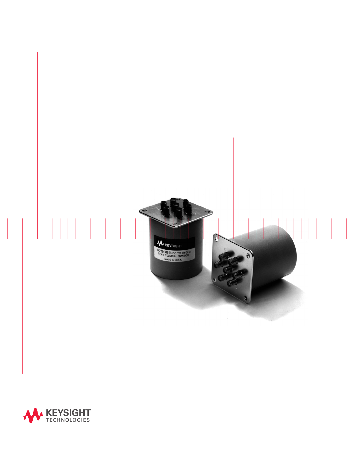
Figure 1. Keysight 87204A/B/C and 87206A/B/C simplified schematics
Operating to 4 GHz (A models),
20GHz (B models), and 26.5 GHz
(C models), these switches exhibit
exceptional isolation performance
required to maintain measurement
Option 100 provides solder terminal
connections in place of the 16-pin
ribbon drive cable. Option 100 does
not incorporate the “open all paths”
feature.
integrity. Isolation between ports
is typically >100 dB to 12 GHz and
>90 dB to 26.5 GHz. This reduces
the influence of signals from other
channels, sustains the integrity of the
measured signal, and reduces system
measurement uncertainties. These
switches also minimize measurement
uncertainty with low insertion loss
and reflection, which makes them
ideal elements in large, multi-tiered
switching systems.
Each port is individually controlled
by its corresponding “close” and
“open” control lines. All open paths
are terminated with 50-ohm loads.
A port is closed or open when its
corresponding “close” or “open” pin
is connected to ground. At this point,
the current to the solenoids is shut
off by the optoelectronic interrupts.
This improves reliability and extends
the life of the switch by eliminating
dc circuit contact failures characterisBoth the 87204A/B/C and
87206A/B/C are designed to fall
within most popular industry footprints. The 2¼ inch square flange
provides mounting holes, while the
rest of the 2½ inch long by 2¼ inch
tic of conventional electromechanical
switches. This configuration allows
compatibility with the Keysight
87130A and Keysight 70611A switch
drivers’ position monitoring and
reporting feature.
diameter body will easily fit into most
systems. Ribbon cable or optional
solder terminal connections accommodate the need for secure and
efficient control cable attachment.
2
Page 3
Applications
Multiport switches find use in a large
number of applications, increasing
system flexibility and simplifying
system design.
Simple signal routing
The simplest signal routing scheme
takes the form of single input to
multiple outputs. These matrixes are
often used at the input of an analyzer to test several two-port devices
sequentially or to test multiport
devices. In surveillance applications,
a multiport switch can be used to
select the optimum antenna for
intercepting a signal.
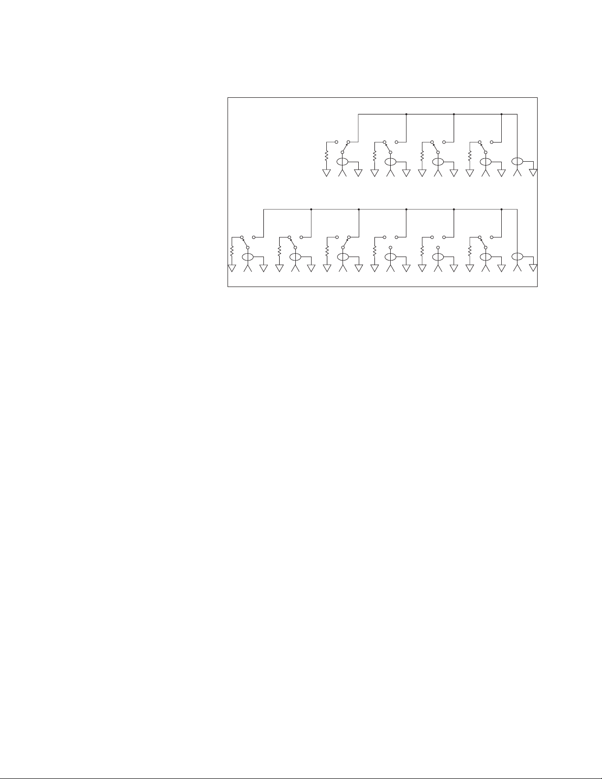
Two methods can be used to accomplish the single input to multiple output arrangement. Traditionally, where
isolation greater than 60 dB was
required, a tree matrix composed of
SPDT switches was used. While this
provided high isolation, it was at the
cost of more switches (Figure 2). The
87204 and 87206 switches have portto-port isolations typically greater
than 90 dB at 26.5 GHz, eliminating
the need for a tree matrix to achieve
high isolation (Figure 3). In addition
to the reduced part count, the path
lengths are shorter, so insertion
loss is less. Also, paths are of equal
length, so phase shift is constant.
Figure 2. Tree matrix
Figure 3. Multiport matrix
Full access switching
Full access switching systems have
the flexibility to route multiple input
signals to multiple outputs simultane-
ously. Full access switching matrixes
are used in test systems to provide
flexible routing of signals between
different devices under test and
stimulus and analysis instrumenta-
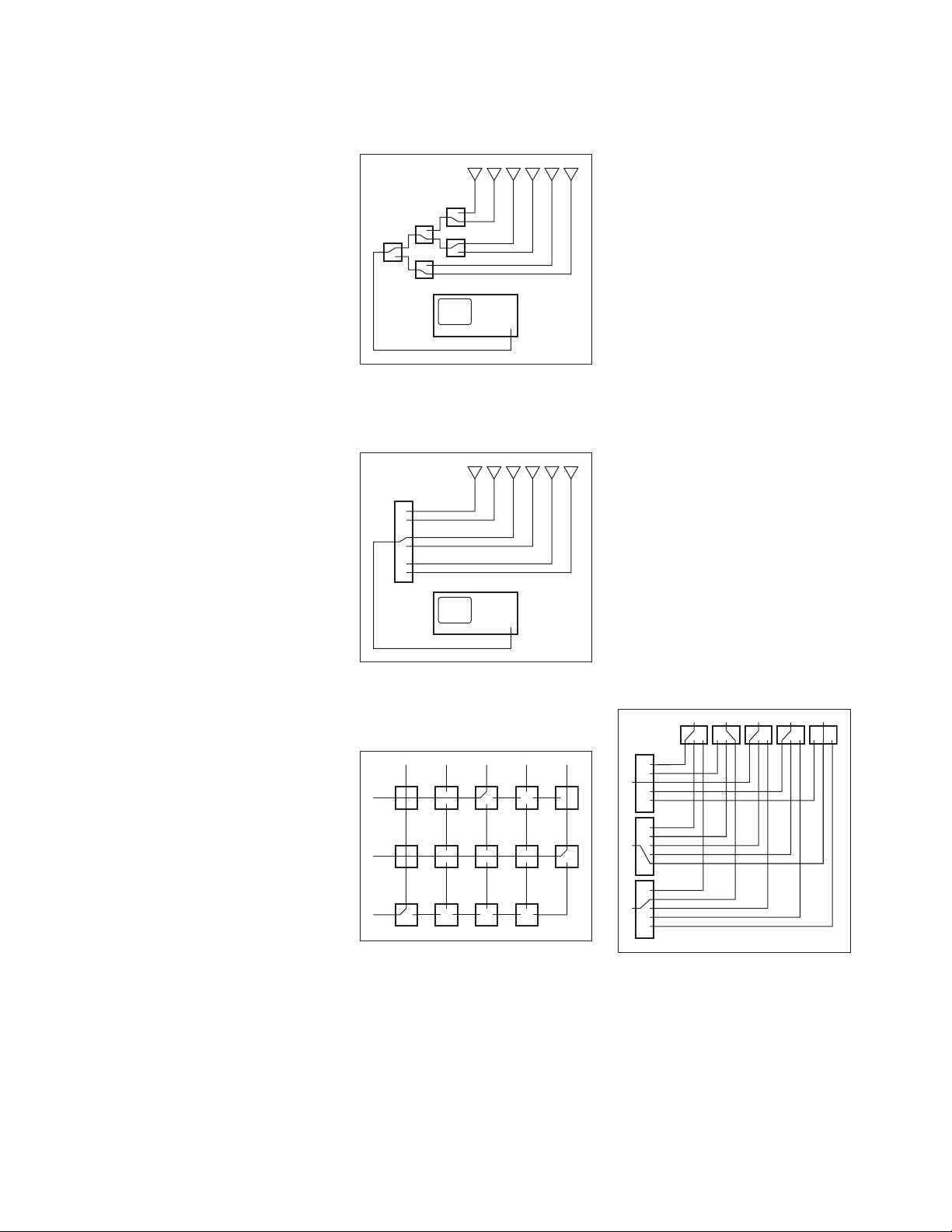
tion. Cross-point matrixes, using
single-pole double-throw and cross-
point switches, have traditionally
been used to maintain high channel-
to-channel isolation (Figure 4). As
with the tree matrixes, this is at the
cost of hardware and performance.
Full access switching can also be
achieved using multiport switches
(Figure 5).
The advantage of the multiport matrix
over the cross-point matrix is lower
insertion loss and improved SWR
performance due to consistent path
length and fewer switches and con-
necting cables.
Figure 4. Cross-point matrix
3
Figure 5. Full access matrix
Page 4

Dedicated switching
There are a number of applications
where switching will be used, not for
flexibility, but to accomplish a particular function within an instrument.
For example, switched filter banks for
reducing harmonics in the output of
sources or at the input of analyzers
can use multiport switches in series
to select the right filter for the band
of interest.
Driving the switch
Each RF path is controlled independently. An “open” or “closed” signal
must be sent to achieve the desired
state for each section of the switch
(see Figure 8 on page 9 for drive connection diagrams).
– Connect pin 1 to supply (+20 Vdc
to +32 Vdc).
– Connect pin 15 to ground (see
Note 1).
– “Open” desired RF path by apply-
ing ground to the corresponding
“open” pin; for example, ground
pin 4 to open RF path 1 (see
Notes 2, 3).
– Close desired RF path by apply-
ing ground to the corresponding
RF path “close” pin; for example,
ground pin 3 to close RF path 1
(see Notes 2, 3).
– To open all RF paths, ensure
that RF path “close” pins are
disconnected from ground. Then,
connect pin 16 to ground. Note:
This feature is not available with
Option 100.
For larger switching systems, where
many switches will be used to
provide complex signal routing, a
switch driver such as the Keysight
87130A or 70611A is recommended.
The 87130A rack-and-stack switch
driver and the MMS-based 70611A
are convenient, flexible GPIB or MSIB
switch controllers, providing driver
circuitry, position monitoring, and
reporting, and firmware that makes it
easy to integrate switch components
into a switching system.
The 87130A must be controlled by
either a PC or workstation-based
GPIB controller and appropriate
software (for example, Keysight ITG
or VEE).
1
The 70611A gives manual control via
the MMS user interface or can also
be controlled via a GPIB-equipped PC
or workstation.
Accessory cables and adapters make
it easy to connect an 87204/87206
to the 87130A (see Ordering
Information). In addition, the built-in
firmware makes it possible to define
frequently used switch paths. With
the path command, macros can be
designed which open and close the
right solenoids to select the desired
switch port; this path may then be
named.
A programmable wake-up condition
makes it possible to ensure that the
matrix or switching system starts up
in a predetermined state.
For smaller switching needs, the
Keysight 11713B 10-channel attenua-
tor/switch controller provides simple
GPIB control for one 87206 and one
87204 or two 87204 switches with
Option 100. Connecting cables can be
ordered that make it easy to connect
the switches to the 11713B (see
Ordering Information).
Notes:
1. Pin 15 must always be connected to ground to enable the electronic position-indicating circuitry
and drive logic circuitry.
CAUTION: IF PIN 15 IS NOT CONNECTED TO POWER SUPPLY GROUND,
CATASTROPHIC FAILURE WILL OCCUR.
2. After the RF path is switched and latched, the drive current is automatically interrupted by the
electronic position-sensing circuitry. Pulsed control is not necessary, but if implemented, the
pulse width must be 15 ms minimum to ensure that the switch is fully latched.
3. Make-before-break switching can be accomplished by closing the new RF path before opening
the old RF path. This will simultaneously engage the old RF path and the new RF path. Once the
new RF path is engaged (15 ms), open the closed path by grounding the RF path open select
pin. Break-before-make is accomplished by opening the old RF path before closing the new
RFpath.
4
1. ITG: Instrument Test Generator, VEE: Visual
Engineering Environment
Page 5

Specications
Specifications describe the instrument’s warranted performance.
Supplemental and typical characteristics are intended to provide
information useful in applying the
instrument by giving typical, but not
warranted performance parameters.
Maximum power rating
Into internal termination 1 W CW, 50 W pk, 10 us max pulse duration, not to
exceed 1 W average
Into thru path
Hot switching
Cold switching
Life 5,000,000 cycles minimum
Switching speed 15 ms maximum
2 W CW, 100 W pk, 10 us max pulse duration, not to
exceed 2 W average
150 W CW at 3 GHz, 25 °C
120 W CW at 4.2 GHz, 25 °C
Environmental specications
Operating temperature –25 to 75 °C
Storage temperature –55 to 85 °C
Temperature cycling –55 to 85 °C, 10 cycles per MIL-STD-202F, Method 107D,
Condition A (modified)
Vibration
Operating 7 g: 5 to 2000 Hz at 0.25 in p-p
Survival 20 g: 20 to 2000 Hz at 0.06 in p-p, 4 min/cycle, 4 cycles/
axis
Random 2.41 g (rms) 10min/axis
Shock
Half-sine 500 g at 0.5ms, 3 drops/direction, 18 total
Operating 50 g at 6 ms, 6 directions
Moisture resistance 65°C, 95% RH, 10 days per MIL-STD-202F, Method 106E
Altitude storage 50,000 feet (15,240meters per MIL-STD-202F, Method
105C, Condition B)
RFI Per MIL-STD-461C, RE02, Part 4
Magnetic field <5 gauss ¼ inch from surface
Physical specications
Dimensions Per Figure 9 on page 10
Weight 229 gm (0.50 lb)
5
Page 6

02
-0.4 -0.3 -0.2 .0.1
S21 (dB)
Typical
Specified
-0.8 -0.7 -0.6 -0.5
5
10 15 20 25
Frequency (GHz)
Figure 6. Insertion loss
Typical
90 110130 150
Isolation (dB)
50 70
010152
Specified
5
Frequency (GHz)
Figure 7. Isolation
5
6
Page 7

Switch drive specications
Parameter Conditions Min Nom Max Units
Supply Voltage, Vcc 20 24 32 V
Supply Current, Icc Switching: Pulse width ≥ 15 ms Vcc = 24 Vdc 2001
Supply Current, Icc (quiescent) 25 50 mA
1. Closing one RF path requires 200 mA. Add 200 mA for each additional RF path closed or opened.
87204A
87206A
Frequency range dc to 4 GHz dc to 20 GHz dc to 26.5 GHz
Insertion loss (see Figure 6) 0.3 dB + 0.015 x frequency (GHz) 0.3 dB + 0.015 x frequency (GHz) 0.3 dB + 0.015 x frequency (GHz)
Isolation (see Figure 7) 100 dB minimum 100 dB minimum to 12 GHz
SWR 1.2:1 maximum 1.2 maximum dc to 4 GHz
Repeatability
(Up to 5 million cycles
measured at 25 °C)
Connectors SMA (f) SMA (f) SMA (f)
0.03 dB maximum 0.03 dB maximum 0.03 dB maximum
87204B
87206B
80 dB minimum to 12 to 15 GHz
70 dB minimum to 15 to 20 GHz
1.35 maximum 4 to 12.4 GHz
1.45 maximum 12.4 to 18 GHz
1.7 maximum 18 to 20 GHz
87204C
87206C
100 dB minimum to 12 GHz
80 dB minimum to 12 to 15 GHz
70 dB minimum to 15 to 20 GHz
65 dB minimum to 20 to 26.5 GHz
1.2 maximum dc to 4 GHz
1.35 maximum 4 to 12.4 GHz
1.45 maximum 12.4 to 18 GHz
1.7 maximum 18 to 26.5 GHz
7
Page 8

Supplemental characteristic
MAX incident CW power (cold switching) vs. frequency
200
100
90
80
70
60
50
40
30
CW power (Watts)
20
10
0.1
0.2
0.3 0.4 0.5 0.6 0.7
1.0
2345678
Frequency (GHz)
Reference conditions:
– Cold switching only (NO Hot switching)
– Ambient temperature of 75 °C or less
– Sea level (0.88 derating @ 15,000 ft.)
– Load VSWR < 1.2 (see graph for derating above 1.2 VSWR)
Power derating factor versus VSWR
1
0.9
0.8
0.7
10.0
18
0.6
Power derating factor
0.5
1 1.5 2 2.5 3
VSWR (:1)
8
Page 9

Standard Option 100
* Paths 1 and 4 not connected for the 87204A/B/C.
** “Open all paths” is not available with Option 100.
Figure 8. Drive connection diagrams
Warning:
1. Grounding both a “close” an
“open” pin of the same path
simultaneously will cause rapid
cycling and premature failure of
theswitch.
2. Grounding any “close” pin and pin
16 simultaneously will cause rapid
cycling and premature failure of the
switch.
Troubleshooting
Symptom Probable cause
1. Will not switch – Not connected to supply
– Supply < 20 V
– Insufcient supply current
– Pin 15 not connected to ground
– Select line not at ground
2. Switch buzzes – “Open” and “close” pins on same RF path are
selected simultaneously
– Pin 16 and any “closed” pins are selected
simultaneously
9
Page 10

23.35
(0.920)
5.7
(0.224)
21.43
(0.860)
26.97
(1.062)
56
3
2
45.72
(1.800)
57.15
(2.250)
Square
13.49
(0.531)
13.49
(0.531)
4.37
ø
(0.172)
60
8.40
(0.331)
71.88
(2.83)
76.96
(3.03)
Dimensions
in millimeters
and (inches)
11.94
(0.470)
6.00
(0.236)
6.00
(0.236)
Solder terminals
56
ø
41
32
45.72
(1.800)
57.15
(2.250)
Square
(0.172)
Figure 9. Product outlines
4.37
60
2.18
(0.086)
63.13
(2.486)
57.15
(2.250)
14.86
(0.585)
Ribbon cable connector
10
Page 11

Ordering information
Switches
87204A dc to 4 GHz, SP4T terminated
87204B dc to 20 GHz, SP4T terminated
87204C dc to 26.5 GHz, SP4T terminated
87206A dc to 4 GHz, SP6T terminated
87206B dc to 20 GHz, SP6T terminated
87206C dc to 26.5 GHz, SP6T terminated
Option 100 Solder terminals to replace ribbon cable
Option 161 16-pin DIP socket and connector with 24-inch ribbon cable
Option UK6 Test data for commercial calibration with certicate
Note: 24 Vdc and Option 161 are default options for dc drive and connector option.
Drivers
11713B Attenuator switch driver Drives up to 10 sections of switches or attenuators.
5061-0969 Accessory cable Viking connector to bare tinned wires (60 inches long). Use to connect 11713B to 87204/206
with Option 100. One required with 87204 Option 100; two required with 87206 Option 100.
70611A Attenuator/switch driver When expanded with up to 8 external (standard only) 84940A driver cards, the 70611A will drive
up to 248 switch or attenuator sections. See below for accessories.
Related literature
Publication title Pub number
Keysight RF and Microwave Switch Selection Guide 5989-6031EN
11
Page 12

012 | Keysight | 87204/87206A, B, C Multiport Coaxial Switches - Technical Overview
myKeysight
www.keysight.com/find/mykeysight
A personalized view into the information most relevant to you.
www.axiestandard.org
AdvancedTCA® Extensions for Instrumentation and Test (AXIe) is an
open standard that extends the AdvancedTCA for general purpose and
semiconductor test. Keysight is a founding member of the AXIe consortium.
www.lxistandard.org
LAN eXtensions for Instruments puts the power of Ethernet and the
Web inside your test systems. Keysight is a founding member of the LXI
consortium.
www.pxisa.org
PCI eXtensions for Instrumentation (PXI) modular instrumentation delivers a
rugged, PC-based high-performance measurement and automation system.
Three-Year Warranty
www.keysight.com/find/ThreeYearWarranty
Keysight’s commitment to superior product quality and lower total cost
of ownership. The only test and measurement company with three-year
warranty standard on all instruments, worldwide.
Keysight Assurance Plans
www.keysight.com/find/AssurancePlans
Up to five years of protection and no budgetary surprises to ensure your
instruments are operating to specification so you can rely on accurate
measurements.
www.keysight.com/quality
Keysight Electronic Measurement Group
DEKRA Certified ISO 9001:2008
Quality Management System
Keysight Channel Partners
www.keysight.com/find/channelpartners
Get the best of both worlds: Keysight’s measurement expertise and product
breadth, combined with channel partner convenience.
For more information on Keysight
Technologies’ products, applications or
services, please contact your local Keysight
office. The complete list is available at:
www.keysight.com/find/contactus
Americas
Canada (877) 894 4414
Brazil 55 11 3351 7010
Mexico 001 800 254 2440
United States (800) 829 4444
Asia Pacic
Australia 1 800 629 485
China 800 810 0189
Hong Kong 800 938 693
India 1 800 112 929
Japan 0120 (421) 345
Korea 080 769 0800
Malaysia 1 800 888 848
Singapore 1 800 375 8100
Taiwan 0800 047 866
Other AP Countries (65) 6375 8100
Europe & Middle East
Austria 0800 001122
Belgium 0800 58580
Finland 0800 523252
France 0805 980333
Germany 0800 6270999
Ireland 1800 832700
Israel 1 809 343051
Italy 800 599100
Luxembourg +32 800 58580
Netherlands 0800 0233200
Russia 8800 5009286
Spain 0800 000154
Sweden 0200 882255
Switzerland 0800 805353
Opt. 1 (DE)
Opt. 2 (FR)
Opt. 3 (IT)
United Kingdom 0800 0260637
www.keysight.com/find/mta
For other unlisted countries:
www.keysight.com/find/contactus
(BP-06-09-14)
This information is subject to change without notice.
© Keysight Technologies, 2013 - 2014
Published in USA, August 3, 2014
5965-3309EN
www.keysight.com
 Loading...