

Page 1

Service Guide
Agilent Technologies
8711C/12/13C/14C
RF Network Analyzers
and
8730A Tuner Analyzer
Manufacturing Part Number: 08712-90059
Printed in USA
Print Date: February 1998
Supersedes October 1996
© Agilent Technologies, Inc. 1996, 1998
Page 2

Hewlett-Packard to Agilent Technologies Transition
This manual may contain references to HP or Hewlett-Packard. Please note that
Hewlett-Packard's former test and measurement, semiconductor products and chemical analysis
businesses are now part of Agilent Technologies. To reduce potential confusion, the only
change to product numbers and names has been in the company name prefix: where a product
number/name was HP XXXX the current name/number is now Agilent XXXX. For example,
model number HP478A is now model number Agilent 478A.
Documentation Warranty
THE MATERIAL CONTAINED IN THIS DOCUMENT IS PROVIDED "AS IS," AND IS
SUBJECT TO BEING CHANGED, WITHOUT NOTICE, IN FUTURE EDITIONS. FURTHER, TO THE MAXIMUM EXTENT PERMITTED BY APPLICABLE LAW, AGILENT
DISCLAIMS ALL WARRANTIES, EITHER EXPRESS OR IMPLIED WITH REGARD TO
THIS MANUAL AND ANY INFORMATION CONTAINED HEREIN, INCLUDING BUT
NOT LIMITED TO THE IMPLIED WARRANTIES OF MERCHANTABILITY AND FITNESS FOR A PARTICULAR PURPOSE. AGILENT SHALL NOT BE LIABLE FOR
ERRORS OR FOR INCIDENTAL OR CONSEQUENTIAL DAMAGES IN CONNECTION
WITH THE FURNISHING, USE, OR PERFORMANCE OF THIS DOCUMENT OR ANY
INFORMATION CONTAINED HEREIN. SHOULD AGILENT AND THE USER HAVE A
SEPARATE WRITTEN AGREEMENT WITH WARRANTY TERMS COVERING THE
MATERIAL IN THIS DOCUMENT THAT CONFLICT WITH THESE TERMS, THE WARRANTY TERMS IN THE SEPARATE AGREEMENT WILL CONTROL.
DFARS/Restricted Rights Notice
If software is for use in the per formance of a U.S. Government prime contract or
subcontract, Software is delivered and licensed as “Commercial computer software” as
defined in DFAR 252.227-7014 (June 1995), or as a “commercial item” as defined in FAR
2.101(a) or as “Restricted computer sof tware” as defined in FAR 52.227-19 (June 1987) or
any equivalent agency regulation or contract clause. Use, duplication or disclosure of
Software is subject to Agilent Technologies’ standard commercial l icense terms, and
non-DOD Departments and Agencies of the U.S. Government will receive no greater than
Restricted Rights as defined in FAR 52.227-19(c)(1-2) (June 1987) . U.S. Government users
will receive no greater than Limited Rights as defined in FAR 52.227-14 (June 1987) or
DFAR 252.227-7015 (b)(2) (November 1995), as applicable in any technical data.
Page 3

Printing Copies of Documentation from the Web
To print copies of documentation from the Web, download the PDF file from the Agilent
web site:
•Go to http://www.agilent.com.
• Enter the document’s pa rt number (located on the title page) in the Quick Search box.
• Click GO.
• Click on the hyperlink for the document.
• Click the printer icon located in the tool bar.
Page 4

Contacting Agilent
This information supersedes all prior HP contact information.
Online assistance: www.agilent.com/find/assist
Americas
Brazil
(tel) (+55) 11 3351 7012
(fax) (+55) 11 3351 7024
Canada
(tel) +1 877 894 4414
(alt) +1 303 662 3369
(fax) +1 800 746 4866
Mexico
(tel) 1 800 254 2440
(fax) 1 800 254 4222
Asia Pacific and Japan
Australia
(tel) 1 800 802 540
(fax) 1 800 681 776
(fax) 1 800 225 539
Japan (Bench)
(tel) 0120 421 345
(alt) (+81) 426 56 7832
(fax) 0120 01 2144
Taiwan
(tel) 0800 047 669
(fax) 0800 047 667
(fax) 886 3492 0779
China
(tel) 800 810 0508
(fax) 800 810 0507
Japan (On-Site)
(tel) 0120 421 345
(alt) (+81) 426 56 7832
(fax) 0120 012 114
Thailand
(tel) 1 800 2758 5822
(fax) 1 800 656 336
Hong Kong
(tel) 800 933 229
(fax) 800 900 701
Singapore
(tel) 1 800 275 0880
(fax) (+65) 675 5 1214
Malaysia
(tel) 1800 880 399
(fax) 1800 801 054
Europe
Austria
(tel) 0820 87 44 11*
(fax) 0820 87 44 22
France
(tel) 0825 010 700*
(fax) 0825 010 701*
Italy
(tel) (+39) (0)2 9260 8484
(fax) (+39) (0)2 9544 1175
Spain
(tel) (+34) 91 631 3300
(fax) (+34) 91 631 3301
Switzerland (Italian)
(tel) 0800 80 5353 opt. 3*
(fax) (+41) (0)22 567 5314
(tel) = primary telephone number; (alt) = alternate telephone number; (fax) = FAX number; * = in country number
Belgium
(tel) (+32) (0)2 404 9340
(fax) (+32) (0)2 404 9395
Germany
(tel) 01805 24 6333*
(fax) 01805 24 6336*
Luxemburg
(tel) (+32) (0)2 404 9340
(fax) (+32) (0)2 404 9395
Sweden
(tel) 0200 88 22 55*
(alt) (+46) (0)8 5064 8686
(fax) 020 120 2266*
United King dom
(tel) (+44) (0)7004 666666
(fax) (+44) (0)7004 444555
Denmark
(tel) (+45) 7013 1515
(fax) (+45) 701 3 1555
Ireland
(tel) (+353) (0)1 890 924 204
(fax)(+353) (0)1 890 924 024
Netherlands
(tel) (+31) (0)20 547 2111
(fax) (+31) (0)20 547 2190
Switzerland (French)
(tel) 0800 80 5353 opt. 2*
(fax) (+41) (0)22 567 5313
United States
(tel) 800 829 4444
(alt) (+1) 303 662 3998
(fax) 800 829 4433
India
(tel) 1600 112 626
(fax) 1600 113 040
South Korea
(tel) 080 778 0011
(fax) 080 778 0013
Finland
(tel) (+358) 10 855 2100
(fax) (+358) (0) 10 855 2923
Israel
(tel) (+972) 3 9288 504
(alt) (+972) 3 9288 544
(fax) (+972) 3 9288 520
Russia
(tel) (+7) 095 797 3963
(alt) (+7) 095 797 3900
(fax) (+7) 095 797 3902
Switzerland (German )
(tel) 0800 80 5353 opt. 1*
(fax) (+41) (0)1 272 7373
5/6/05
Page 5
Service Guide
HP
RF
HP
8711C/12C/13C/14C
Network
8730A
and
Tuner
Analyzers
Analyzer
ABCDE
HP Part No. 08712-90059
Printed in USA February 1998 Supersedes October 1996
Page 6

Notice.
The
information contained
in
this
document
is
subject
to
change
without
notice
.
Hewlett-P
but
purpose
ackard makes
not limited
.
Hewlett-P
consequential
R
R
is
a
Windows
TORX
to
,
the
ackard
damages
is
a
registered
registered
no
warranty
implied
warranties
shall
in
connection
trademark
trademark
not
of
of
be
with
of
TORX
liable
any
kind
of
merchantability
for
errors
the
furnishing,
Microsoft
Products
with
regard
contained
performance
Corporation.
,
division
to
this
and
of
Camcar/T
material,
tness
herein
,
or
for
or
for
use
extron
including
a
particular
incidental or
of
this
Corporation.
material.
c
Copyright 1996, 1998 Hewlett-Packard Company
Page 7
Certication
Hewlett-P
time
of
shipment
ackard
measurements
T
echnology
facilities
of
,
to
other
Regulatory
The
regulatory
Safety
Refer
How
This
4
F
N
N
N
N
to
to Use
guide
ront-Panel
N
NN
N
N
N
N
N
N
N
N
N
N
N
N
N
,
W
arranty
Chapter
Key
N
N
N
Softkey
Company
from
the factory
are
traceable
the extent
International
Information
information
,
and
9
for
information on
This
uses
5
This
This
the
represents
indicates
rmware
the
eight
certies
that this
. Hewlett-P
to
the United
allowed by
the Institute's
Standards Organization
is
in
the
User's
Assistance
safety,
Guide
following
a
,
and
is
unlabeled
conventions:
a
key
physically
\softkey
displayed
keys
product met
ackard further
States National
Guide
supplied
warranty,
located
,"
a
key
whose
on
the
right
.
its published
certies that
Institute of
calibration facility
members.
with
the
analyzer
and
assistance
on
the
instrument.
label
is
determined
side
of
the
instrument's
specications at
its calibration
Standards and
,and
to the
calibration
.
.
by
the
screen
the
instrument's
next
to
Screen
This
HP
HP
HP
HP
HP
Note
Text
guide
8711C
8712C
8713C
8714C
8730A
This
indicates
contains
text
displayed
servicing
on
the
information
instrument's
for
the
screen.
following
instruments:
Servicing information for the HP 87030A tuner test set is included in a
manual.
separate
iii
Page 8

Page 9
Contents
1.
P
erformance
System
P
erforming
Instructions
Specications
Measurement
Source
Receiver
System
Make
a
Make
a
Make
a
If the
Analyzer F
Introduction
Estimated
Equipment
File
Structure
Conguration
Getting
P
erformance
Conguration
The
The
The
The
The
The
The
The
The
The
The data directory and MSUS . . . . . . . . .
The sensor's
The step attenuator's 40 dB card selection (3) . . . . . . . . . . . . . .
The
The
Sensors .
20 dB Attenuators (P
External 10 dB Step Attenuator .................... 1-18
UsingtheProgram............................. 1-19
Main Menu ...... ...... ..... ...... ...... .. 1-19
Test Selection Menu .... ...... ...... ...... .... . 1-20
Miscellaneous Information ..... ..... ...... ...... .. 1-21
Individual Test Notes and Descriptions ................... 1-21
Frequency Accuracy. ..... ...... ...... ...... ... 1-21
T
ests
Summary
P
ort
Specications
Specications
Specications
Specications
the
Operator's
Transmission
Broadband
Reection
for
Using
.
Time
.
.
File
Started
T
est
analyzer's
ISC
for
power
spectrum
function
attenuator
frequency
voltmeter model
printer address
program directory
device)
serial numbers (xxxx) . . . . . . . . . . . . . . . . . . . . .
beeper (on)
current DUT le sux (1)
.
Measurement
P
ower
Measurement
ails
the
the
.
.
.
.
.
.
.
.
.
.
.
.
.
.
.
.
.
.
Software
Menu
the
meter
, external 10 dB step attenuator's
...... ...... ...... ...... .
.
HP-IB
test
model
analyzer
generator
switch
counter
.
.
.
.......................
.
.
.
.
.
.
.
.
.
.
.
.
.
.
.
.
.
.
.
.
.
.
.
.
.
.
.
.
.
.
.
.
Check
Operator's
Analyzer
.
.
.
.
.
.
.
.
.
.
.
.
address
equipment
number (HP
(01) .
.
.
ads) . . . . . . .
.
.
.
.
Measurement
.
.
Check
P
erformance
.
.
.
.
.
.
.
.
.
.
.
.
.
.
.
.
.
.
.
.
.
.
.
.
.
.
.
.
.
..
Installation
.
.
.
.
.
(716)
(7)
number
(HP
model number
driver
model
and the
.
..
(HP 437B)
8566B)
model
number
.
.
.
mass storage
.
.
....................
.
.
.
.
.
.
.
.
.
3456A)
.
.
.
.
.
.
.
.
.
.
.
..
..
..
.
.
.
.
.
.
.
.
.
.
..
..
.
.
.
.
.
.
..
..
..
..
.
.
.
.
.
.
.
.
.
..
..
..
.
.
.
.
.
.
.
.
.
..
..
..
.
.
.
.
.
.
..
..
..
.
.
.
.
.
.
.
.
.
.
.
..
..
..
.
.
.
.
.
.
.
.
.
.
.
..
..
.
.
.
.
.
.
.
.
.
.
.
.
.
.
.
.
.
.
.
.
.
.
.
.
.
.
.
T
est
Software
.
..
..
..
.
.
.
.
.
..
.
.
.
.
..
..
.
.
.
..
..
.
.
.
.
.
.
.
.
.
.
.
.
.
.
.
.
.
.
.
.
..
.
.
.
..
.
.
.
.
.
.
.
.
.
.
.
.
.
.
.
..
and address
and address
(HP 8116A)
number (HP
(HP 5342A)
.
.
.
.
.
.
.................
(18) .
and address
11713A) and
and address
and
address
.
.
.
.
unit specier
.
.
.
.
.............
, and xed attenuator's (pad's)
..
..
.
.
.
..
.
.
.
.
.
.
..
..
.
.
..
.
.
.
.
.
.
.
.
(13)
.
(22)
.
.
.
.
.
.
.
.
.
.
.
.
.
.
.
.
.
.
.
.
.
.
.
.
.
.
.
.
.
.
.
.
.
.
.
.
.
.
.
address (28)
.
.
.
.
.
(the
.
.
.
.
.
.
.
.
.
.
.
.
.
.
.
.
(14) .
(02) .
.
..
current
.
......
..
.
.
.
.
.
.
.
.
.
.
.
.
.
.
.
.
.
.
.
.....
..
..
.
.
.
.
.
.
.
.
.
.
.
.
..
.
..
..
.
.
.
.
.
.
.
.
.
.
.
.
.
.
.
.
.
.
.
.
.
.
.
.
.
.
.
.
..
.
.
...
.
.
.
.
.
.
.
.
.
.
.
.
.
.
.
.
.
. 1-10
..
.
.
.
.
.
.
.
.
.
.
.
.
.
.
.
.
.
.
.
.
.
.
.
.
.
.
.
.
.
.
..
MSI
.
.
. 1-18
1-2
1-2
1-2
1-3
1-5
1-6
1-7
1-8
1-9
1-11
1-11
1-11
1-12
1-14
1-15
1-15
1-16
1-16
1-16
1-16
1-16
1-16
1-16
1-17
1-17
1-17
1-17
1-17
1-17
1-17
1-17
1-18
1-18
1-18
Contents-1
Page 10
Gain
Compression .
Noise
Floor .
Dynamic
P
ower Flatness
Absolute
Broadband
Directivity
Spurs
AM
Trace
2.
A
djustments
Correction
Fractional-N
Required
W
armup
Estimated
Procedure
Fractional-N
Required
W
armup
Estimated
Procedure
Frequency
Required
W
armup
Estimated
Procedure
Set
Serial
Required
Estimated
Procedure
In
Case
LO
P
ower
Required
W
armup
Estimated
Procedure
Switched
Required
Warmup Time . . . . . . .
Estimated A
Procedure....... ....
External Detector Correction, A
Required Equipment . . . . . . . . . . . . . . . . . . . .
WarmupTime ..... ..... ...... ....
Estimated A
Procedure....... ...... .... ...... .
Auxiliary Input Correction, Adjustment #111 .... ...... ...... . 2-21
Required Equipment . . . . . . . . . . . . . . . . . . . . . . . . . . . . 2-21
WarmupTime ..... ..... ...... ...... ...... .. 2-21
Estimated Adjustment Time ....................... 2-21
Procedure....... ...... .... ...... ...... .... 2-21
Source Power (ALC) Correction, Adjustment #104 .. ...... ...... . 2-22
Required Equipment . . . . . . . . . . . . . . . . . . . . . . . . . . . . 2-22
Accuracy
Power
(includes
(including
Delay
Modulator
Noise
Constants
V
CO
Equipment
Time
A
.
.
Spur
Equipment
Time
A
.
.
A
ccuracy
Equipment
Time
A
.
.
Number
Equipment
Adjustment
..
of
Diculty
Correction,
Equipment
Time
A
.
.
Gain
Correction,
Equipment
Frequency Response
.
A
djustment
djustment
.
A
djustment
..
djustment
.
,
A
.
djustment
.
djustment Time
djustment Time ....................
..
.
.
.
.
.
.
.
.
.
.
A
ccuracy
source
harmonics)
(Option
.
.
.
.
(CCs)
A
.
.
.
.
.
.
.
.
Time
.
.
.
.
djustment
.
.
.
.
.
.
.
.
Time
..
.
Adjustment
.
..
.
.
..
.
Time
.
.
.
.
djustment
.
.
.
Time
.
.
.
.
.
A
djustment
.
.
.
.
.
.
.
.
Time
.
.
.
.
A
.
.
.
.
.
.
.
.
.
.
.
.
.
.
.
.
..
..
..
.
.
.
.
.
.
.
..
..
..
..
..
..
..
.
.
.
.
.
.
.
.
.
..
..
..
..
..
..
.
.
.
.
.
.
.
..
..
..
..
..
..
.
.
.
.
.
.
.
.
.
..
..
..
..
..
.
.
.
.
.
.
.
.
.
.
.
..
..
match,
.
.
.
djustments
.
.
.
.
.
.
.
.
..
.
.
.
.
..
.
.
.
..
.
.
.
.
.
#100
.
.
.
.
.
.
.
.
.
.
.
.
.
.
.
djustment
..
djustment #103
test
port
match,
.
.
.
.
.
.
.
.
1D
A/1DB
.
.
.
.
.
.
.
.
.
.
..
.
.
.
.
..
.
.
.
.
..
.
.
.
.
.
..
.
.
.
.
.
.
.
.
.
.
#101
.
.
.
.
.
.
.
.
.
.
.......................
..... ..
...... ...... ...... ....
.
.
.
.
.
.
.
..
.
.
.
.
.
.
.
..
.
.
.
.
.
.
.
.
.
.
.
.
.
.
.
.
.
.
.
.
.
.
.
.
.
.
.
.
.
.
.
.
#102
.
.
analyzers
..
..
.
.
.
.
.
..
..
.
..
..
..
..
..
..
.
.
.
.
.
.
.
.
.
.
.
.
.
.
.
.
..
..
.
.
.
.
.
.
.
.
.
.
.
.
.
.
.
.
.
.
.
.
.
.
.
.
.
.
.
.
.
.
.
.
.
.
.
.
.
.
.
.
.
.
.
.
.
.
.
.
.
.
.
.
.
.
..
.
.
.
.
.
..
..
..
..
.
.
.
.
...... ...... ....
................
.
.
only)
..
..
..
..
.
.
..
.
.
.
.
.
..
.
.
..
.
.
.
.
.
.
.
.
.
.
.
.
.
.
.
.
.
.
.
.
..
.
.
.
..
..
.
.
..
..
.
.
and
.
..
..
..
.
.
.
.
.
.
.
.
..
.
.
.
..
.
.
.
.
.
.
.
.
.
.
.
.
.
.
.
.
.
.
.
.
..
..
..
..
.
.
..
..
.
..
reection
..
..
.
.
.
.
.
.
.
.
.
.
..
..
.
.
.
.
.
.
.
.
.
.
.
.
.
.
.
.
.
.
.
.
.
.
.
.
.
.
.
.
.
.
.
.
.
.
.
.
.
.
.
.
.
.
.
.
.
.
.
.
.
.
.
.
.
.
.
.
.
.
.
.
.
.
.
.
.
.
.
.
.
.
..
.
.
.
.
.
.
.
.
.
.
.
.
.
.
.
.
.
.
.
..
..
.
.
.
.
.
..
..
..
..
.
.
.
.
.
.
.
..
..
..
.
.
.
.
..
..
.
.
.
.
........
...... ....
.........
..
..
.
.
..
..
.
.
..
..
..
..
tracking)
..
.
.
..
..
.
.
.
.
.
.
.
.
.
.
.
.
.
.
.
.
.
.
.
.
.
.
.
.
.
.
.
.
.
.
.
.
.
.
.
.
.
.
.
.
.
..
..
.
.
.
.
.
.
.
.
.
.
..
.
.
.
.
.
.
.
.
.
..
..
.
.
.
.
.
..
.
.
.
.
.
.
.
.
.
.
.
.
.
.
.
.
.
.
..
.
.
.
.
.
.
.
.
.
.
.
.
...
.
.
.
.
.
.
.
.
.
.
..
.
.
.
..
.
.
.
.
.
.
.
.
.
.
.
.
.
.
..
.
.
.
.
.
.
.
.
.
.
.
.
.
1-21
.
1-22
.
1-22
.
1-23
.
1-23
1-24
.
1-24
.
1-25
. 1-26
.
1-26
.
2-3
.
2-4
.
2-4
.
2-4
.
2-4
.
2-4
.
2-7
.
2-7
.
2-7
.
2-7
.
2-7
.
2-11
2-11
.
2-11
.
2-11
.
2-11
.
2-14
.
2-14
. 2-14
.
2-14
.
2-15
.
2-16
.
2-16
.
2-16
.
2-16
.
2-16
.
2-17
.
2-17
2-17
2-17
2-17
2-19
2-19
2-20
2-20
2-20
Contents-2
Page 11
W
armup Time
Estimated
Procedure
In
Case of
B
Amplitude Correction,
Required
W
armup
Estimated
Procedure
Transmission
Required
W
armup
Estimated
Procedure
B*
Amplitude
Required
W
armup
Estimated
Procedure
AM
Delay
Required
W
armup
Estimated
Procedure
Reection
Required
W
armup
Estimated
Procedure
R*
Amplitude
Required
W
armup Time
Estimated
Procedure
R*
Frequency
Required
W
armup
Estimated
Procedure
Adjustment
..
.
Diculty
Equipment .
Time
A
djustment
.
.
.
(B/R)
Equipment
Time
A
djustment
.
.
.
Correction,
Equipment
Time
A
djustment
.
.
.
Correction,
Equipment
Time
A
djustment
.
.
..
(One-P
ort)
Equipment
Time
A
djustment
.
.
.
Correction,
Equipment .
Adjustment
.
.
.
Response
Equipment
Time
A
djustment
.
.
.
..
.
.
.
Time
.
.
.
.
.
.
.
A
djustment
.
.
.
.
.
.
.
Time
.
.
.
.
.
Correction,
.
.
.
.
.
.
.
.
Time
.
.
.
.
.
A
djustment
.
.
.
.
.
.
.
.
Time
.
.
.
.
.
A
djustment
.
.
.
.
.
.
.
.
Time .
..
.
.
Correction, A
.
.
.
.
.
..
.
Time
.
.
.
.
.
A
djustment
.
.
.
.
.
.
.
Time
.
.
.
.
.
Correction,
.
.
.
.
.
.
.
.
Time
.
.
..
..
.
.
.
.
.
.
.
.
.
.
.
.
.
.
.
.
.
.
#105
.
.
.
.
.
.
.
.
.
.
.
.
.
.
.
.
.
.
A
djustment
.
.
.
.
.
.
.
..
..
.
.
.
.
.
.
..
#110
.
.
.
.
.
.
.
.
.
..
.
.
.
.
.
.
.
.
#112
.
.
.
.
..
.
..
..
..
.
.
.
.
.
djustment #107
..
.
.
.
.
.
.
.
.
.
.
.
.
.
.
.
.
#108
.
.
.
.
.
.
.
.
.
.
.
.
.
.
.
.
.
.
A
djustment
.
.
.
.
.
.
.
.
.
.
.
.
.
..
..
.
.
.
.
..
.
.
.
.
.
.
..
.
.
..
#106
.
.
..
.
.
..
.
.
..
.
.
.
..
.
.
..
..
.
.
.
.
.
.
.
.
.
.
.
.
.
.
.
.
.
.
..
.
.
.
.
.
.
..
.
.
.
.
..
.
..
.
.
.
.
..
.
.
..
.
.
..
.
..
..
.
.
..
..
.
..
.
.
.
..
..
.
.
.
.
.
.
.
.
.
.
.
.
.
.
.
.
.
.
.
.
..
.
.
.
..
.
.
..
.
..
.
.
..
..
.
.
..
..
.
.
..
.
.
..
.
..
.
.
.
.
..
.
..
.
.
.
.
.
.
.
.
.
.
.
.
.
.
.
.
.
.
.
.
.
.
.
.
.
.
.
.
..
#109
.
.
..
.
.
.
.
..
.
..
..
..
.
.
..
..
.
..
..
.
.
..
.
.
..
.
.
.
.
..
.
.
.
.
.
.
.
.
.
.
.
.
.
.
.
.
.
.
.
.
.
.
.
.
.
.
.
.
.
.
.
.
.
..
.
..
..
.
.
.
.
..
..
..
..
.
..
..
.
..
.
.
.
.
..
.
.
..
.
.
..
.
.
.
.
.
.
.
.
.
.
.
.
.
.
.
.
.
.
.
.
.
.
.
.
.
.
.
.
.
.
.
.
.
.
.
.
.
.
.
.
..
..
.
..
.
.
..
..
..
..
..
..
.
.
..
.
.
.
.
..
.
.
.
.
.
..
.
.
.
.
.
.
.
.
..
.
.
.
.
.
.
.
.
.
.
.
.
.
.
.
.
..
.
.
.
.
.
..
.
.
.
.
.
.
..
.
..
.
.
..
..
..
..
..
..
.
.
..
.
.
..
.
.
.
.
.
.
.
.
..
.
.
.
.
.
.
.
.
.
.
.
.
.
.
.
.
.
.
.
.
.
.
.
.
.
.
.
.
.
.
.
.
..
.
.
.
.
.
.
.
.
.
.
..
.
.
..
..
.
.
..
..
..
.
.
.
.
.
..
.
.
.
.
.
.
.
.
.
.
.
.
.
.
.
.
.
.
.
.
.
.
.
.
.
.
..
.
.
.
.
.
.
.
.
.
.
.
.
..
.
.
.
.
.
.
.
.
.
.
.
..
.
.
.
..
.
.
.
..
..
.
.
.
.
.
.
..
.
.
.
.
.
.
.
.
.
.
.
.
.
.
.
.
.
.
.
.
.
.
.
.
.
.
..
.
.
.
.
.
..
..
.
.
.
.
..
.
.
.
..
.
.
..
.
.
.
.
.
.
..
.
.
. 2-22
.
.
.
.
. 2-25
.
.
.
.
.
.
.
.
..
.
.
.
.
.
.
.
.
.
.
.
.
.
.
.
.
.
.
.
.
.
.
.
.
.
.
.
.
.
.
.
.
.
.
.
.
.
.
.
.
.
.
.
. 2-30
.
.
..
.
.
.
.
.
.
. 2-31
2-22
2-22
2-23
2-25
2-25
2-25
2-25
2-26
2-26
2-26
2-26
2-26
2-27
2-27
2-27
2-27
2-27
2-28
2-28
2-28
2-28
2-28
2-29
2-29
2-29
2-29
2-29
2-30
2-30
2-30
2-30
2-31
2-31
2-31
2-31
3. Assembly Replacement
Introduction . . . . . . . . . .
Required T
Major Assembly Removal/Replacement
A1 Front P
How to Remove the Front P
A2 CPU Board Assembly Replacement
How to Remove the CPU Board Assembly . . . . . . . . . . . . . . . . . .
A3 Fractional-N/Reference Assembly Replacement . . . . . . . . . . . . . . . 3-8
How to Remove the Fractional-N/Reference Assembly .... ...... .. 3-8
A4 Source Assembly Replacement ...... ...... .... ..... . 3-9
How to Remove the Source Assembly . . . . . . . . . . . . . . . . . . . . 3-9
A5 Receiver Assembly Replacement . . . . . . . . . . . . . . . . . . . . . . 3-10
How to Remove the Receiver Assembly . . . . . . . . . . . . . . . . . . . 3-10
A6 Power Supply Assembly Replacement .... ...... ...... ... 3-12
ools.........
anel Assembly Replacement
.......................
......................
...................
...... ...... ....
anel Assembly
...... ...... ...
...... ..... ...... ..
....
..
3-1
3-1
. 3-2
3-3
3-4
. 3-5
3-6
Contents-3
Page 12
How
to Remove
A7
Display Assembly
How
to Remove
How
to replace
How
to A
A8
3.5" Internal
How
to
Remove
Attenuator
AM
Delay
P
ost
Repair
How
Save
Save
4.
Troubleshooting
Introduction
General
Service
How
Initial
Operator's
Category
Error
Troubleshooting
Check
Measure
Remove
Troubleshooting
Error
Error
Clear
Measure
Front
Other
Other
Category
Troubleshooting
Check
Phase Lock Problems
Detailed Fractional-N/Reference Troubleshooting
Troubleshooting the A4 Source Assembly
Troubleshooting the A5 Receiver Assembly
A5 Receiver Assembly Diode Replacement
Trace at6200 dB
Detailed Receiver Troubleshooting
Category 3 F
Troubleshooting Spurious Responses and Inaccurate Data .......... 4-25
Spurious Signals . . . . . . . . . . . . . . . . . . . . . . . . . . . . . 4-25
Spurs in the Data Trace .......... ...... ...... ... 4-26
Inaccurate Data ...... ...... ..... ...... .... .. 4-26
Receiver Power Problems .... ...... ...... ...... .. 4-27
Category 4 Failures: Peripheral Device Problems . . . . . . . . . . . . . . . . 4-28
DINKeyboard........ ...... .... ...... ...... . 4-28
Replacement
Modulator
Procedures
to
Order
Money
Time
Notes
Kit
to
Use
Observations
1
F
Messages
the
During
T
est
Status
T
est Status
Occurs During
the
P
anel
P
ower-Up
Error
2
F
the
the P
ower
Supply
Replacement
the
Display
the
power
djust
the
P
osition
Disk
Drive
Assembly
the
3.5"
Disk
.
.
.
Replacement
.
.
.
.
P
arts
.
.
.
.
.
by
Ordering
by
Calling
and
.
.
.
.
.
.
.
.
.
the
Extender
Check
ailures
the
Assemblies
the
ailures
ailures - Inaccurate (but reasonably functional) Measurements
-
on
A6
Rear
Panel
P
ower
Digital
P
ower-up
LEDs
LEDs
Nonvolatile
5
MHz
Problems
Problems
messages
-
the
Output
R-E
(800)
227-8164
Block
.
.
.
-
.
Dead
the Display
P
No
A3
P
Diagrams
.
.
.
.
.
.
.
..
.
.
.
.
Board
Normal
.
.
.
.
or
No
ower Supply
LEDs .
Supply
.
.
.
Group
.
.
.
.
.
.
code
.
DSP
Initialization
SRAM
Reference
.
.
.
.
.
.
.
Error
Fractional-N/Reference
ower
..
...... .
...... ...... ......
Assembly
.
.
.
.
.
Assembly
switch
of
the
Drive
.
.
.
.
.
.
(Rebuilt-Exchange)
.
.
..
..
P
ower-up
.
.
Response
..
.
Voltages
..
Problems
.
.
.
.
.
.
.
Signal
.
.
.
.
.
.
Message
.
.
.
or
brightness
CRT
Replacement
.
.
.
.
..
..
..
Assembly Problems
.
.
.
.
.
.
.
.
.
.
.
Assembly
.
.
.
.
.
.
.
.
.
.
.
..
.
..
..
.
.
.
..
..
..
.
.
.
.
.
.
.
.
.
Sequence
..
..
,No
.
.
.
.
.
.
.
.
.
.
.
.
.
.
.
.
.
.
.
.
.
.
.
.
.
.
.
.
.
or
Calculating
.
.
.
.
.
.
.
.
.
.
.
.
.
.
.
.
.
.
,
but
Nonfunctional
.
.
.
.
...................
.......
...... ...... ...... ..
.
.
.
.
.
.
.
.
.
.
..
.
.
.
.
.
..
..
..
..
.
.
.
.
.
.
..
..
..
..
control
.
.
.
.
.
.
.
..
.
.
.
..
..
Assemblies
.
..
.
.
.
.
.
.
.
.
.
.
.
.
.
Display,
.
.
.
.
.
.
.
.
.
.
.
.
.
.
.
.
.
.
.
.
.
.
.
.
.
.
.
.
.
.
.
.
..
.
.
.
.
.
.
Assembly
.
.
.
.................
...... ...... ....
.
.
.
.
.
..
..
..
..
.
.
.
.
.
.
.
..
.
.
.
.
..
..
..
..
..
.
.
.
..
..
..
..
..
.
.
.
.
..
.
.
.
.
.
.
.
.
.
..
..
..
.
.
.
.
.
.
.
.
.
.
.
.
.
.
.
.
.
.
.
.
.
.
.
.
.
.
.
.
..
.
.
.
.
.
.
.
.
.
.
.
.
.
.
.
.
.
.
.
.
Unreadable Display
.
.
.
.
.
.
.
.
.
.
.
.
.
.
.
.
.
.
.
.
.
.
.
.
.
.
.
.
.
.
.
.
.
.
.
.
.
.
.
.
.
.
.
.
.
.
.
.
.
.
.
.
.
.
.
.
.
.
.
.
..
.
.
.
.
.
.
.
.
Coecients
.
.
.
..
.
.
.
..
..
..
.
..
..
..
..
Measurement
.
.
.
..
.
........
...... .....
.
..
.
..
..
.
.
.
..
.
..
..
..
..
.
.
.
...... ....
..
..
..
..
.
.
..
.
.
.
.
..
.
.
.
.
.
.
.
.
.
.
.
..
.
.
.
.
.
.
.
.
.
.
.
.
.
.
..
.
.
..
.
.
.
.
..
.
.
.
.
.
.
..
.
.
.....
..
..
..
..
..
..
..
.
.
.
.
.
.
.
.
..
.
.
.
.
.
.
.
.
.
.
.
.
.
,or
.
.
.
.
.
.
.
.
.
.
.
.
.
.
.
.
..
.
.
.
.
.
.
.
.
.
.
.
.
.
..
.
.
...
..
..
..
..
.
.
.
.
.
..
.
.
.
.
.
.
.
.
.
..
.
.
.
.
.
.
.
.
.
.
.
.
.
.
3-12
3-13
. 3-13
3-13
3-13
. 3-14
.
3-14
.
3-14
.
3-14
.
3-15
.
3-16
3-16
.
3-16
.
4-1
.
4-1
.
4-3
.
4-4
.
4-5
.
4-6
.
4-7
.
4-7
4-7
.
4-8
.
4-9
.
4-9
.
4-9
.
4-10
.
4-10
.
4-14
.
4-14
.
4-14
.
4-15
.
4-15
.
4-16
.
4-17
. 4-17
.
4-17
4-17
4-18
4-19
4-19
4-21
4-24
4-24
4-25
Contents-4
Page 13
RS-232
Centronics
HP-IB
LAN
5.
Service
Introduction
T
ests
Select
Select
Instrument
Update
Service
Meas
Analog
Service
Service
View
Miscellaneous
Clearing
HP-IB
Syntax
Softkey
Alphabetical
Printers and
(Parallel)
Systems .
HP-IB
General
Ping
How
T
A
Problems with
Checks for
Troubleshooting (Option
Command
to
Ping
esting
Between
vailable
Related
and
A
djustments
Self-T
est
A
djustment
Info
Corr
Utilities
Cal
Options
Bus
Menu
Utilities
Utilities
Array
Master
Nonvolatile
Command
Summary
SCPI
HP
.
.
Menu
Const
Service
Commands
SCPI
Plotters .
Printers
.
.
.
.
.
.
Two
LAN
Cables
Menus
.
.
.
Menu
Menu
.
.
.
Menu
Menu
1
Menu
.
.
Menu
2
Menu
3 .
Menu/View Array
Functions
Memory
Reference
.
Command
.
.
.
Printers
HP-IB
.
.
.
.
.
.
Analyzers
.
.
.
.
.
.
.
.
.
.
.
.
.
.
.
.
.
.
.
.
.
.
..
for
.
.
.
.
.
and
Plotters
.
.
.
or
Systems
1F7)
.
.
.
.
.
.
.
.
.
.
..
.
.
.
.
.
.
.
.
.
..
..
.
.
.
.
.
.
.
.
.
.
..
.
.
.
.
.
..
(SRAM)
Service
.
.
.
.
.
.
Summary
.
.
.
.
.
.
.
.
.
.
.
..
Plotters
.
.
.
.
.
.
.
.
.
..
.
.
.
.
..
.
.
..
.
..
.
.
.
.
..
..
.
.
Interpol Menu
..
.
.
.
.
.
.
.
.
.
.
..
.
.
.
..
.
..
.
..
.
..
.
.
.
.
..
..
.
.
.
.
..
..
.
.
.
.
.
.
.
.
.
.
..
..
.
.
.
.
..
..
..
..
.
.
.
.
.
.
.
.
.
..
.
.
.
.
.
.
.
.
.
.
.
.
.
.
..
.
.
.
.
..
.
..
.
..
.
.
..
.
.
..
.
.
.
.
.
.
.
.
.
.
.
.
..
.
.
.
.
.
.
..
..
.
.
..
.
.
..
.
..
.
.
.
.
.
..
.
.
.
.
.
.
.
.
.
.
.
.
.
.
.
.
.
.
.
.
.
..
.
.
.
.
..
.
..
.
.
.
.
.
.
.
.
.
.
.
.
.
.
.
.
.
.
.
.
.
.
.
.
.
.
.
.
.
.
.
.
.
.
..
.
.
.
..
..
..
.
.
..
.
.
.
.
.
.
.
.
.
.
.
.
.
.
.
.
.
.
.
.
.
.
.
..
..
..
.
..
..
..
.
.
.
..
..
.
.
.
.
.
.
.
.
.
.
.
.
.
.
.
.
.
.
.
.
.
.
.
.
.
.
.
.
.
.
.
.
.
.
.
.
..
..
..
..
..
..
.
.
.
.
..
.
.
.
.
.
.
.
.
.
.
.
.
.
.
.
.
.
.
.
.
.
.
.
.
.
.
.
.
.
.
.
.
..
.
.
.
.
..
..
.
..
..
..
.
.
.
.
..
.
.
.
.
.
.
.
.
.
.
.
.
.
.
.
.
.
.
.
.
.
.
.
.
.
.
.
.
.
.
.
.
.
.
.
..
.
.
..
..
.
..
..
.
.
.
.
.
.
.
.
.
.
.
.
.
.
.
.
.
.
.
.
.
.
.
.
.
.
.
.
.
..
.
.
.
.
.
.
.
.
.
.
.
..
..
.
.
..
.
.
.
.
.
.
.
.
.
.
.
.
.
.
.
.
.
.
.
.
.
.
.
4-28
4-28
.
4-29
. 4-29
. 4-29
. 4-29
.
4-30
.
4-30
.
4-31
.
4-33
.
5-1
.
5-2
.
5-2
.
5-4
.
5-6
.
5-6
.
5-7
.
5-9
.
5-9
.
5-11
. 5-11
.
5-12
.
5-12
.
5-12
.
5-13
.
5-13
.
5-13
.
5-14
6.
Theory of
Introduction
System
Analyzer
P
ower
Digital
A1
A2
A7
A8 3.5" Internal Disk Drive Assembly . . . .
Source Theory . . . . . . . . .
A3 Fractional-N/Reference Assembly
A4SourceAssembly...................
Receiver Theory . . . . . . . . . . . . . . . . . . . .
Dierences Between the HP 8711C/12C/30A and HP 8713C/14C (1300 MHz vs
HP 8713C/14C A4 Source Assembly . . . . . . . . . . . . . . . . . . . .
A5 Receiver Assembly . . . . . . . . . . . . . . . . . . . . . . . . . . 6-8
Operation
.
.
.
.
.
.
.
.
.
.
.
.
.
.
.
..
..
.
.
.
.
Theory
Supply
Control
Front
CPU
Display
3000 MHz) . . . . . . . . . . . . . . . . . . . . . .
.
.
Functional
Theory
Theory
P
anel
Assembly
Assembly
Assembly
.
.
Group
.
.
.
.
.
.
.
.
.
..
..
..
..
.
.
.
.
.
.
.
.
.
.
.
.
.
.
..
.
.
.
.
.
.
.
.
.
.
.
.
..
..
..
.
.
.
.
.
.
.
.
.
.
.
.
.
..
..
.
.
.
..
..
..
..
.
.
.
.
.
.
..
..
..
..
..
..
.
.
.
.
.
..
.
.
.
.
.
.
.
.
.
.
.
..
...............
...... ...... ...... ....
...... ...
.
.
.
.
..
.
..
.
.
.
.
.
.
..........
..........
...... ...
.
.
.
.
.
.
.
.
.
.
.
.
.
.
.
.
..
.
.
.
.
.
.
.
.
.
.
.
.
.
.
..
.
.
.
.
.
.
.
.
.
.
.
.
.
.
.
.
.
.
.
.
.
.
.
.
.
.
.
.
.
.
...... ..
6-1
6-1
6-2
6-2
6-2
6-2
6-2
6-3
6-3
6-4
6-4
6-4
6-5
6-7
6-7
Contents-5
Page 14
7.
Parts
List
Analyzer
Specic
8.
Correction Constants
Storing
Storing
Loading
Storing
Installing
In
Upgrading
How
9.
Safety
Safety
General
Safety
Servicing
W
arranty
Limitation
Exclusive
Assistance
Shipment
Hardware .
Assembly and
and Recalling
Correction
Correction
Correction
Correction
Case
of
or
to
Upgrade
,
W
arranty
Symbols
Safety
Earth
.
.
for
Cable
Correction
Constants
Constants
Constants
Diculties
Re-Installing
or
Re-Install
,
and
.
.
.
Considerations
Ground
.
.
.
.
.
.
.
.
.
.
of
W
arranty
Remedies .
.
..
..
Service
..
.
.
.
.
.
Locations
and
Firmware
to
from
to
Constants
.
.
.
.
Firmware
the
Assistance
.
.
.
.
.
.
.
.
.
.
.
.
.
.
.
.
.
.
.
.
.
.
.
.
.
..
..
.
.
.
.
.
..
.
.
.
.
.
.
.
Constants
Disk
EPROM
from
.
.
.
.
.
.
.
..
.
.
.
Disk
Disk
.
.
.
.
.
Firmware
.
..
.
.
.
.
..
.
.
.
.
.
..
..
..
.
.
.
.
.
.
.
.
.
.
.
.
(CC)
.
.
.
.
.
.
.
.
.
.
.
..
..
..
..
.
..
.
.
.
.
.
.
..
.
.
.
.
.
.
.
.
.
.
.
..
.
.
.
.
..
..
.
.
.
.
.
.
.
.
.
.
.
.
.
..
.
.
.
.
.
.
.
.
.
.
.
.
..
..
.
..
.
.
..
.
.
.
.
.
.
.
.
.
.
.
.
.
.
..
.
.
.
.
.
.
.
.
.
.
.
.
..
..
..
.
.
.
.
.
.
.
.
.
.
.
.
.
.
.
.
.
.
..
..
.
.
..
.
..
.
..
.
.
..
..
..
.
.
.
.
.
.
.
.
.
.
.
.
.
.
.
.
.
.
..
..
.
..
..
..
..
..
.
.
..
..
.
.
.
.
.
.
.
.
.
.
.
.
.
.
.
.
.
.
..
..
..
..
..
..
..
.
.
.
.
.
.
.
.
.
.
.
.
.
.
.
.
.
.
.
..
.
.
..
..
..
..
..
..
..
.
.
.
.
.
.
.
.
.
.
.
.
.
.
.
.
.
.
.
..
..
.
..
.
.
..
..
.
.
.
.
..
.
.
.
.
.
.
.
.
.
.
.
.
.
.
.
.
.
.
..
.
.
..
.
7-1
. 7-1
8-1
.
8-2
.
8-3
.
8-3
.
8-3
.
8-3
.
8-4
.
8-4
.
9-1
.
9-2
.
9-2
.
9-2
.
9-3
.
9-3
9-3
.
9-4
9-4
Index
Contents-6
Page 15
Figures
1-1. Equipment
1-2. Typical
1-3. Typical
1-4. Typical
1-5. Connect
2-1.
Removing
2-2.
TP11
2-3.
Removing
2-4.
Setup
2-5.
API
and
2-6.
Setup
2-7.
Removing
2-8. External
2-9.
Setup
3-1.
Removing
3-2.
Removing
3-3.
BootROM
3-4.
Removing
3-5.
Removing
3-6.
Anchoring
3-7.
A8
Disk
4-1.
Example
4-2.
Connecting
4-3.
P
ower
4-4.
HP
8711C/12C/30A
4-5.
HP
8713C/14C
4-6.
HP 8711C/12C/30A
4-7.
HP 8713C/14C
Locations
4-8.
Construction of
4-9.
HP
8711C/12C/30A
4-10. HP 8713C/14C A4 Source and A5 Receiver Assemblies Block Diagram . . . . .
5-1. The Service Key Menus
6-1. Simplied Analyzer System Block Diagram
6-2. Simplied HP 8711C/12C/30A A4 Source Block Diagram
6-3. Simplied Receiver Block Diagram
8-1. Correction Constants Flow by Keystroke and Cycling P
Setup
HP
8713C/14C
HP
8713C/14C
HP
8713C/14C
the
the
and
L162
the
for
Fractional-N
100
for
Frequency
the
Detector
for
Source
the
the
U335,
the
the
Screw
Drive
of
the
Supply
for
Transmission
Transmission
Broadband
Reection
Load
kHz
an
.
.
.
.
.
.
Handles
for
Handles
Handles
Handles
CPU
Component
Fractional-N/Reference
A4
Jumper
Antistatic
Extender
Connector
Reection
A5CR45, CR46,
..
a Cross-over
and
Fractional-N
and
Spur
A
djustments
A
ccuracy
and
Connector
P
ower
Correction
and
Assembly
Source
Locations
Assembly
Conguration
W
Board
,
as
Reection
Measurement
A5CR1, CR2,
..
..
Overall
.
Front
Front
A
djustments
Front
,
Front
Front
.
Location
for
orkstation
Viewed
Measurement
CR47, CR48,
..
Cable .
Block
.........................
Measurement
Measurement
P
ower
Measurement
.
.
.
.
P
anel
V
CO
A
djustment
P
anel
.
.
.
.
A
djustment
P
anel
View
.
.
P
anel
Assembly
.
.
.
.
.
Assembly
.
.
A5
Receiver
.
.
.
.
.
.
from
with
CR36, and
.
.
.
.
..
Diagram
...
.
.
.
.
.
.
.
.
.
.
.
.
.
.
.
.
.
.
.
.
.
.
.
.
Measurement
.
.
.
.
.
.
.
.
.
.
.
.
.
.
.
.
.
.
.
.
.
.
.
.
.
.
.
.
.
.
.
.
.
.
.
.
.
.
.
.
.
.
.
.
Removal
.
.
.
.
.
..
..
..
..
Rear P
.
anel .
with
Through
CR37
CR53, and
.
.
.
..
.
.
.
.
.
................
...... ...... ......
.
.
.
.
.
.
.
.
.
.
.
.
.
.
.
.
.
.
..
..
..
.
.
.
.
.
..
..
.
.
.
.
.
.
.
..
.
.
.
.
.
..
..
.
.
.
.
.
.
.
.
.
.
.
.
.
.
.
.
.
.
.
.
.
.
.
.
.
.
.
.
.
.
.
.
.
.
..
.
.
.
.
.
.
.
.
.
.
.
.
.
.
.
.
.
..
.
.
.
.
.
.
.
.
.
.
.
.
.
.
.
..
.
.
.
.
.
..
.
.
.
.
.
.
.
.
.
.
.
.
.
.
.
..
.
.
.
.
.
.
.
.
.
.
.
.
.
.
.
..
.
.
.
.
.
.
.
.
.
.
.
.
.
.
.
.
.
.
.
.
.
.
.
Through
Component
.
.
.
.
.
.
Cable .
Cable
CR54
.
.
..
ower ...... ...
.
..
Locations
Component
.
.
.
.
.
.
.
.
.
.
.
.
.
.
.
.
.
...... .....
.
.
.
.
.
.
..
..
..
..
..
.
.
..
..
..
.
.
..
.
.
.
..
.
.
.
.
.
.
.
.
.
.
.
.
..
..
..
.
.
.
.
.
.
.
.
.
.
.
.
..
.
.
..
.
.
..
..
..
.
.
.
.
.
.
.
.
.
.
.
..
.
.
.
.
.
.
.
.
..
..
.
..
.
.
.
.
.
.
..
.
.
.
.
.
.
.
..
.
..
.
.
.
.
.
.
.
.
..
.
.
.
..
..
.
. 1-7
. 1-7
. 1-8
1-9
.
1-10
.
2-5
.
2-6
.
2-8
.
2-9
.
2-9
.
2-11
.
2-13
2-19
.
2-23
3-3
.
3-5
.
3-6
.
3-8
.
3-9
.
3-10
.
3-14
.
4-2
.
4-5
.
4-8
4-20
.
4-20
.
4-22
4-23
. 4-32
. 4-35
4-37
5-1
6-1
6-5
6-6
8-1
Contents-7
Page 16

T
ables
1-1. Required
3-1.
P
ost
4-1.
Analyzer
4-2.
Source
5-1.
Analyzer
5-2.
Analyzer
5-3.
Analyzer
5-4.
Analog
5-5.
Softkey
5-6.
Alphabetical
7-1.
HP
8711C/12C/30A
7-2. HP
7-3.
7-4.
7-5.
7-6.
7-7.
7-8.
7-9.
7-10.
7-11.
7-12.
7-13.
7-14.
7-15.
9-1.
8713C/14C Major
A1
Front
A2
CPU
A3
Fractional-N/Reference
HP
8711C/12C/30A
HP
8713C/14C
HP
8711C/12C
HP
8711C/12C
Locations
HP
8730A
HP
8713C/14C
HP
8713C/14C
Locations
A6
P
ower Supply
A7
Display
Cabinet
Hewlett-P
Equipment for
Repair
Procedures
Self-T
Frequency
Self-T
A
djustments
Correction
Bus
Nodes
SCPI
P
anel
Assembly
A5
Assembly and
and
Miscellaneous
ackard
ests
.
.
V
ersus
ests
.
.
Constant
.
.
Commands
SCPI
Command
Major
Assembly
Assembly
and
A4
A4
Source
A5
Receiver
A5
Receiver
.
.
.
.
Receiver
A5
Receiver
A5
Receiver
.
.
.
.
Assembly and
Sales
the
A
djustments
.
.
.
.
.
.
.
.
.
.
Fractional-N
.
.
.
.
.
.
.
.
.
.
Storage
.
.
.
.
.
.
.
.
.
Summary
Assembly
and
and
Cable
Cable
Locations
Assembly
Source
.
Assembly
..
and
Assembly
Assembly
Assembly
Optional
.
.
.
.
Assembly
Optional
..
.
Cable Locations
Cable Locations
P
arts .
Service Oces
and
.
.
.
.
.
.
.
.
.
.
Frequency
.
.
.
.
.
.
.
.
.
.
Arrays
.
.
.
.
..
.
.
.
.
.
.
.
and
Cable
Cable
Locations
Locations
.
.
and
Cable
and
and
Cable
and
Cable
Congurations
.
.
..
.
and
Cable
and
Cable
Congurations
.
.
.
.
.
..
..
..
..
P
erformance
.
.
..
.
..
..
.
.
.
.
..
.
.
.
.
.
.
.
..
..
.
.
.
.
.
.
.
.
Locations
.
.
.
.
.
.
.
Locations
Cable
Locations
Locations
Locations
Assembly
.
.
.
.
Locations
Locations
Assembly
.
.
.
.
..
..
.
.
.
.
.
..
.
..
..
.
.
..
.
..
.
.
.
..
.
.
.
.
.
.
.
.
.
.
.
.
.
.
.
.
.
.
.
.
.
T
..
..
.
.
..
..
.
.
.
.
..
.
.
.
.
.
.
.
..
..
.
.
.
.
.
.
.
.
.
.
.
.
.
.
.
.
.
.
.
ests
..
.
.
.
.
.
.
.
..
.
.
.
.
and
.
.
.
and
.
.
.
.
.
.
.
.
.
.
.
.
.
..
.
.
.
.
.
.
.
.
.
.
.
.
..
..
.
.
.
.
.
.
..
.
.
..
.
.
.
.
.
.
.
.
.
.
.
.
.
.
.
.
.
.
.
.
.
.
.
.
.
.
.
.
.
.
.
..
.
.
.
.
.
Cable
.
.
.
.
..
Cable
.
.
.
.
.
.
.
.
.
.
.
.
.
.
..
.
.
.
.
.
.
.
.
.
.
.
.
..
..
.
.
.
.
.
.
.
.
.
.
.
.
.
.
.
.
.
.
.
.
.
..
.
.
.
.
..
.
.
.
.
.
..
.
.
.
.
.
.
.
.
.
.
.
.
.
.
.
.
.
.
.
.
.
.
..
.
.
.
.
.
.
.
.
.
1-13
.
3-15
.
4-11
4-18
.
5-3
.
5-5
. 5-8
.
5-10
.
5-13
5-14
.
7-2
.
7-3
.
7-4
.
7-5
.
7-6
. 7-7
. 7-8
.
7-9
.
7-10
.
7-11
.
7-12
7-13
.
7-14
.
7-15
.
7-16
.
9-5
Contents-8
Page 17
P
erformance T
1
ests
This chapter
the
system
performing
instructions
The
operator's
for
this
Option
The
performance
greater than
check
1EC
analyzers).
is divided
specications
the
for
check
is
a95%
performance test
equivalent),
B
ASIC
nor
are
HP
language
any
test
Note
Note
into
three
summary
operator's
using
the
analyzer
can
be
a
type-N
tests
will
cable
verify
condence
software is
B
ASIC
5.1
or
processor
record
If
you
card
cards
would
08712-10017),
T
able
9-1
in
There
B
requires
and an
for an
is
also
ASIC
language
the
HP-IB interface
HP workstation
parts:
check,
used
as
and
that
level.
written
greater
(HP
provided.
like
to
contact
the
\Safety
a
version
processor
use
of
,
and
performance
a
quick
a
good
quality
the
analyzer
The
performance
for
an
HP
.
However
82324B
order
or
the
your
nearest
,
W
arranty
of
this program
card
HP
B
ASIC for
card.
computer
test
80%
condence
50
meets
9000
Series
,
it
will
equivalent).
analyzer
Hewlett-P
,
and
(see
Chapter 7,
Windows
Operation
.
software
.
test.
type-N
tests
also
load
its
published
are
200,
run
completely
300,
on
There
performance
ackard
Assistance"
that
will
run
\Parts
R
(E2060B),
is
essentially
The
(75
or
aPC
are
no
test
sales
chapter
on
List").
identical
only
equipment
for the
HP 8730A
specication
automated.
700
computer
system with
manual
tests
software
or
service
.
a
PC
without
This
a
separate
to
that
required
with
The
(or
an HP
provided,
(p/n
oce
an
HP
program
program,
described
or
.
See
Results
of the
specications
described
tests
in an
in enough
accurate
automated performance
,
limits
,
and
uncertainties
detail
below
manner
to
.
tests can
.
Although
allow
be
printed
no
manual
a
knowledgeable
out
at
any
test
is
provided,
technician
time
to
perform
.
They
include
each
test
is
all
needed
Performance Tests 1-1
all
Page 18
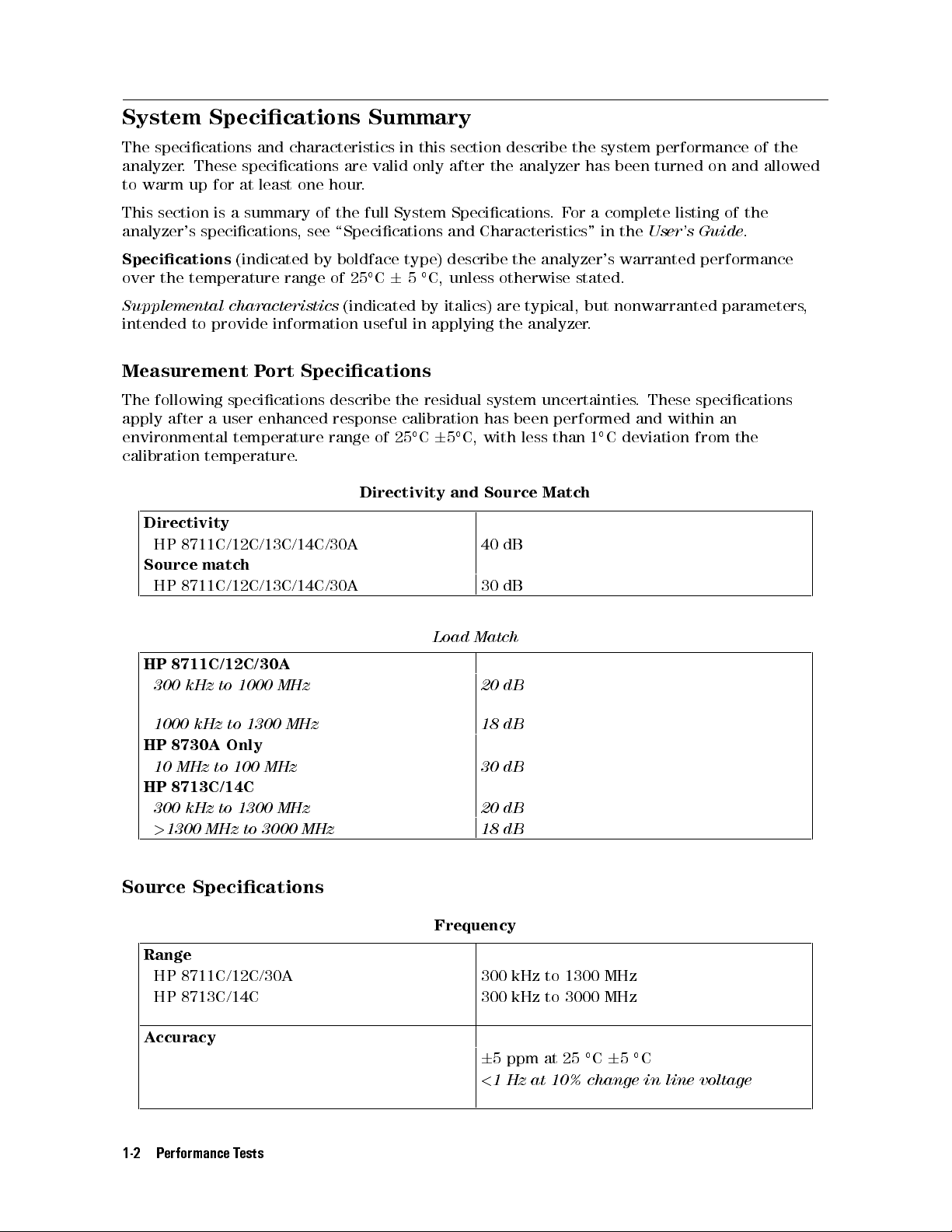
System Specications
The
specications
analyzer
to
This
.
warm
section
analyzer's
These
up
specications
and
specications
for
at least
is
a
summary
characteristics
are valid
one hour
of
the
,
see
\Specications and
Summary
in this
section describe
only after
.
full
System Specications
the system
the analyzer
.F
has been
or a
Characteristics" in
performance of
turned on
complete
the
User's
listing
Guide
the
and allowed
of
the
.
Specications
over
the
temperature
Supplemental
intended to
characteristics
provide information
Measurement
The
following
apply
after
environmental
calibration
specications
a
user
temperature
temperature
Directivity
HP
8711C/12C/13C/14C/30A
Source
HP
match
HP
8711C/12C/13C/14C/30A
8711C/12C/30A
300
kHz
to
(indicated
range
P
ort
enhanced
.
1000
MHz
by
boldface
of 25
type) describe
C
6
5
(indicated
useful in
Specications
describe
response
range
the
calibration
of
25
C
Directivity
C,
unless
by
italics) are
applying the
residual
system
has
C,
5
and
with
Source
6
40
30
Load
Match
20
the analyzer's
otherwise
typical, but
analyzer
uncertainties
been
performed
less
than
Match
dB
dB
dB
warranted performance
stated.
nonwarranted parameters
.
.
C
1
These
and
deviation
specications
within
from
,
an
the
1000
HP
8730A
10
MHz
HP
8713C/14C
300
kHz
>
1300
kHz
MHz
to
Only
to
to
1300
100
1300
to
MHz
MHz
3000
MHz
MHz
18
30
20
18
dB
dB
dB
dB
Source Specications
Frequency
Range
HP 8711C/12C/30A 300 kHz to 1300 MHz
HP 8713C/14C 300 kHz to 3000 MHz
Accuracy
6
5 ppm at 25C65C
<
1 Hz at 10% change in line voltage
1-2 Performance Tests
Page 19
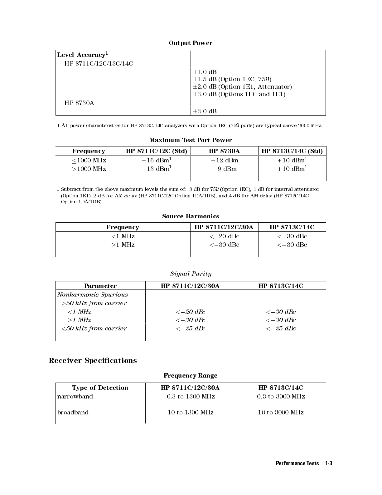
Level A
1
All
ccuracy
HP
8711C/12C/13C/14C
HP
8730A
power
characteristics
Output
Power
1
6
1.0
dB
6
1.5
dB
for
HP
8713C/14C
analyzers
6
6
6
with
2.0
3.0
3.0
Option
dB
dB
dB
(Option
(Option
(Options
1EC
(75
1EC,
1E1,
1EC
ports)
75)
Attenuator)
and
1E1)
are
typical above
2000 MHz.
Frequency HP
1000
MHz
>
1000
MHz
1
Subtract
(Option 1E1),
Option
from
the
2
dB
1DA/1DB).
P
arameter
Nonharmonic
50
kHz from
<
1
MHz
1
MHz
<
50
kHz from
above
for
maximum
AM
delay
Maximum
8711C/12C
+16
dBm
+13
dBm
levels
the
(HP
8711C/12C
Source
(Std)
1
1
sum of:
Option
T
est
Harmonics
Frequency HP
<
1
MHz
1
MHz
Signal
HP
8711C/12C/30A
Spurious
carrier
<
0
20
<
0
30
<
0
carrier
25 dBc
P
ort
P
HP
+12
+9
3dB
for 75
1D
A/1DB),
8711C/12C/30A
<
0
<
0
Purity
dBc
dBc
ower
8730A
dBm
dBm
(Option
and
20
30
4
dB
dBc
dBc
1EC),
for
AM
1
HP
dB
delay
HP
8713C/14C
+10
+10
for
internal
(HP
8713C/14C
HP
8713C/14C
<
0
30
<
0
30
8713C/14C
<
0
30
dBc
<
0
30
dBc
<
0
25 dBc
1
dBm
1
dBm
attenuator
dBc
dBc
(Std)
Receiver Specications
Frequency Range
Type of Detection HP 8711C/12C/30A HP 8713C/14C
narrowband 0.3 to 1300 MHz 0.3 to 3000 MHz
broadband 10 to 1300 MHz 10 to 3000 MHz
Performance Tests 1-3
Page 20
6
0.5 dB
Total
Typical
Frequency R
esponse (broadband)
HP 8711C/12C/30A HP 8713C/14C
6
1.0 dB
T
otal
P
ower
A
ccuracy (broadband)
Power
Accuracy
= Absolute
P
ower
A
ccuracy
+
Frequency
R
esponse
Frequency HP
<
5
MHz
5
MHz
Type
narrowband
broadband
1
6
0.5
dB
compression
2
at
0.55
dB
Absolute
P
ower
>
of
Detection
1
2
compression
A
ccuracy
8711C/12C
(50)
>
60
dB
100
dB
(broadband)
Dynamic
HP
8711C/12C/30A
HP
Range
(Narrowband)
(75)
>
57
dB
>
97
dB
Maximum
Input
8711C/12C/30A
+10
dBm
+16
dBm
HP
8713C/14C
(50)
>
100
>
100
dB
dB
HP
8713C/14C
+10
+16
HP
8713C/14C
(75)
>
97
>
97
dBm
dBm
dB
dB
Insert
artwork here
1-4 Performance Tests
.
Page 21
Dynamic
Accuracy
(narrowband)
Insert
System
medium
narrow
1
3700
2
250
artwork
here
Specications
Trace
P
arameter
IF
IF
bandwidth
Noise
bandwidth
Hz
Hz
.
(Transmission,
1
2
0
dBm,
HP
8711C/12C/30A
6
0.2
6
0.1
excludes
dB
dB
frequency
response)
HP
8713C/14C
6
0.2
6
0.05
dB
dB
Performance Tests 1-5
Page 22
Performing
The
operator's
wish
to
be
condent
verify
high
The
cable
cable
such
Caution
Caution
that
the
degree
operator's
that
,
as
and
one
of
was
making
from
the Operator's
check
condence
check
supplied
should
that the
analyzer
calibration kit
The preset
power
If
The
troubleshooting
same
key
analyzer
4
SYSTEM
N
N
N
N
N
NN
Service
N
NN
N
N
N
Inst
is performing
that the
consists
with your
a measurement
power level
level
you
have
operator's
preset
,
press
the
to
the
OPTIONS
NN
N
N
N
N
N
N
N
N
N
N
N
N
N
N
N
N
N
N
N
N
N
NN
Utilities
N
N
N
N
N
N
N
N
N
N
N
N
N
N
N
N
N
N
N
N
NN
N
N
N
State
be performed
analyzer is
of the
HP 85032B/E
to
0
an
HP
check,
procedures
state
following
preset
5
NN
N
N
N
N
N
N
N
N
N
N
N
N
N
N
N
N
N
N
N
Utilities
Check
when you
working properly
to specications
analyzer is
following: making
analyzer,
with a
dBm
8730A,
as
a
N
N
N
N
N
N
N
N
N
N
Service
N
N
N
N
N
N
N
N
N
N
N
N
N
N
N
N
N
N
N
N
NN
N
making a
50 (or
is
user-denable
if
necessary
please
non-automated
all
standard
keys
to
state
of
N
NN
NN
N
N
N
N
N
N
N
N
N
N
N
N
N
NN
NN
N
N
N
N
N
N
N
N
N
N
N
N
N
N
N
N
Menu
NN
N
N
N
N
N
N
N
Preset
Next
N
N
N
receive your
. The
. Its
purpose is
performing properly
a transmission
reection measurement
75) termination.
(50) or
require
network
a
N
N
N
N
N
N
N
N
N
N
N
N
HP 85036B/E
.
When
.
read
the
adjustment
the
analyzer.
change the
standard network
N
N
N
N
N
NN
NN
N
N
N
N
N
N
N
Next
N
N
N
NN
N
N
N
N
Menu
N
N
N
N
N
N
N
N
8711C
N
N
N
N
N
N
N
N
N
N
N
to
pressing
following
HP
8730A
preset state
N
N
N
N
N
N
N
N
N
N
N
N
N
N
N
N
N
N
N
N
.
analyzer,
operator's check
if it
Use
(75).
procedures
tuner
Instead of
analyzer:
and any
to provide
passes.
measurement with
with
a
known-good
4
PRESET
information
,
and
analyzer
using the
of the
HP
time you
does not
you with
the
load,
5
,
change the
carefully.
to
8730A
a
the
same
have
4
PRESET
tuner
the
5
1-6 Performance Tests
Page 23
Make
1.
Connect the
that
a
Transmission
equipment as
was supplied
Measurement
with your
shown in
analyzer.
Figure 1-1
.Use
aknown
good cable
such
as
the
one
2.
3.
Figure
Press
V
erify
HP
8713C/14C
Figure
OPSETUP
Figure
4
PRESET
that
5
the
(see the
OPTRANS here
data
result.
here
1-1.
cautions
trace
The
.
Equipment
on
falls
within
HP
8711C/12C/30A
.
page
6
Setup
1-6)
0.5
dB
for
Transmission
5
of
4
0
dB.
4
SCALE
should
5
4
.1
ENTER
See Figure
look
similar
Measurement
5
.
1-2 for
,
but
end
a typical
at
1300
MHz.
Figure 1-2. Typical HP 8713C/14C Transmission Measurement
Performance Tests 1-7
Page 24
Make
1.
2.
3. V
a
Leave the
Press
4
MEAS1
erify that
HP 8713C/14C
Broadband
cable connected
N
N
N
N
N
N
NN
NN
NN
NN
More
5
the data
trace.
P
ower
N
N
N
N
N
N
NN
NN
NN
NN
Power
trace is
Measurement
to the
NN
N
4
FREQ
within
analyzer.
N
N
N
N
N
Start
5
6
N
N
N
N
N
4
of
10
5
0
N
NN
MHz
dBm.
NN
N
4
SCALE
See
5
5
4
1
Figure
4
ENTER
1-3
5
.
for
a typical
N
NN
NN
NN
NN
NN
N
2
dB
Figure OPBRO
Figure
1-3.
ADREFL
Typical HP
here
.
8713C/14C
Broadband
P
ower
Measurement
1-8 Performance Tests
Page 25
Make
1.
2.
3. V
a
Leave the
Press
4
PRESET
erify that
HP 8713C/14C
Reection
cable connected
5
(see
the data
trace.
Measurement
to the
the
cautions
trace falls
on page
completely
analyzer.
1-6)
4
MEAS1
below
N
N
N
N
N
N
NN
Reflection
5
0
16
dB
NN
.
NN
NN
See
NN
NN
NN
N
N
N
N
N
N
Figure
N
N
N
N
N
N
.
1-4
for
a
typical
Figure OPREFL
Figure
here
.
1-4.
Typical HP
8713C/14C
Reection
Measurement
Performance Tests 1-9
Page 26
Figure
LO
AD
here
.
Figure 1-5.
4.
Disconnect
Figure
5.
V
erify
N
N
N
N
N
NN
N
N
N
N
N
N
Reference
This
concludes
performing
Measure
(A
175
accuracy
Check
If
the
using
a
Ensure
measure
If the Analyzer F
First,
repeat the operator's check using a dierent cable and load to eliminate these as a
possible cause of failure
the
1-5
.
that
the
N
N
N
N
N
N
N
N
N
N
N
N
N
N
N
N
N
NN
N
Level
the
the
following:
a
known
MHz
lter
and
noise
broadband
analyzer's
frequency
that
the
frequencies.
cable
and
data
N
N
N
N
N
N
N
N
N
N
N
N
N
N
Operator's
lter
is
supplied
oor
response
frequency
counter
analyzer
trace
and
connect
falls
the
to
verify
.
.
is
Check.
with
accuracy
V
placed
below
5
key until
4
+
with
erify
a
known
However
that
its
the
HP
lter
using
is
to
6
in
trigger-hold
ails the Operator's Check
.
0
30
dB
the
measured
Connect
good
.
If the
trace
,
further
the
load
data
moves
response
8711C/12C/13C/14C.)
conversion-loss
critical
.005%
for
your
accuracy
mode
Load
to
the
RF
trace
is
up
onto
condence
is
the
V
mode
application,
(for example
(press
4
MENU
OUT
o
the
can
same
erify
(same
port
the
screen.
be
both
verify
,
6
2500 Hz
NN
NN
N
N
N
Trigger
5
obtained
as
as B*/R*).
N
N
as
shown
screen,
is
expected.
the
aCW
N
N
N
N
N
N
N
N
N
N
N
N
N
N
in
press
4
by
frequency
frequency
at 500
NN
Hold
MHz).
NN
N
N
N
N
N
N
N
N
N
N
)
to
SCALE
5
If your analyzer does not meet the criteria in the operator's check,
your analyzer may
need servicing. Have a qualied service technician check the analyzer or contact any
Hewlett-Packard sales or service oce for assistance
Sales and Service Oces" in Chapter 9, \Safety
. Refer to T
,W
arranty, and Assistance
able
9-1, \Hewlett-P
," for the nearest
oce.
1-10 Performance Tests
ackard
Page 27
Instructions for
Introduction
The
performance
designed
and
HP
8730A
option
HP
An
to
B
compatible
HP B
E2060B.
Note
Note
8730A).
HP
run
ASIC
ASIC for
combinations
9000 Series
the LIF
language
Operation under
to
test software
automate
as
well
200/300/700 (or
version of
processor
computer
Windows is
This
HP
HP
All
with
08712-10012).
you
only
all
,
including
that
program
8711A,
part
the
the
are
the
Using the
,HP
the
performance
as
the required
both
the software
card (HP
has
HP B
a
separate
either platform
cannot
order
number
data
les
previous
It
adding
main
this
program
Analyzer P
part number
verication tests
automated fractional-N
50
and
equivalent) computer
. However
82324B or
ASIC for
product
is
be
used
HP
part
number
08712-10011.
and
conguration les
HP
871xB
is
not
necessary
program
le
08712-10017 (LIF)
75
,
it
equivalent). The
Windows installed
which
nearly
to
test
Both
version
to
to
the
(CAL871XC)
erformance T
for the
spur adjustments
versions (only
with B
will
also
run
may
be
purchased
identical.
an
HP
8711A
08711-10011.
of
these
programs
used in
of
this
program
regenerate
same
directory
need
be
est Software
and 08712-10018
HP 8711C/12C/13C/14C,
.It
the 75
ASIC
on
DOS
and
T
o
this
or
transferred.
5.1
a
PC
version
an
HP-IB
as
or
any
test
are
program
(HP
modify
as
the
versions
or
greater
system
will
HP
HP
871xB
an
HP
in
are
part
any
HP871xB
with
run
interface
model
871xB
LIF
format only
compatible
number
of
these
(DOS), is
will
test
apply
to
is
required
an
HP
on
any
card.
number
.
T
o
test
,
order
les
software
.
all
the
PC
an
.
If
,
The
performance
from
the
disk, although
best
performance
loss
of
data. The
environment.
Operation
4
RETURN
key.
Note
A disk le is generated for
This le is updated after each
be obtained for any previously tested analyzer
Estimated Time
Before running the performance tests
hour.Performance test times are kept to a minimum, allowing analyzers to be fully tested
within one hour after the initial warmup.
5
/
4
is
ENTER
test software
. Generally
LIF version
The
DOS version
a
simple
5
/
4
EXECUTE
All
program.
is
provided
it
is
recommended
,the
program
program
is limited
menu
driven
5
key
can
necessary instructions
each analyzer
test so that results will not be accidentally lost. A printout can
will
system
always
, turn on the analyzer and allow it to warm up for one
on
a
single
disk.
Y
ou
can
run
the
program
that
you
run
it
from
your
system's
can
be
stopped,
operate
to
DOS
with
be
and
, and the results of each test are stored in that le
on
environments
some
used
as
test
setup
.
a
LIF-based
softkey
softkey
diagrams
reset
.
selections
#1:
and
system,
the
are
re-run
.
most
contained
with
or
an
F
or
ease
frequently
hard
directly
disk
little
or
SRM/HFS
of
use
,the
used
within
the
for
no
.
Performance Tests 1-11
Page 28

Note
Equipment
When
testing
disconnected.
communicate
an
HP
Ignore
with
8730A,
any
the
test
the
error
set.
HP
87030A tuner
messages
indicating
test set
that
should be
the analyzer
cannot
Besides
the
equipment
a
computer
that
,
printer
is
required
,
RF
cables
,
BNC
cables
,
to
test
and
adjust
HP-IB
the
cables
analyzer
,
and adapters
.
,T
able 1-1
lists
1-12 Performance Tests
Page 29
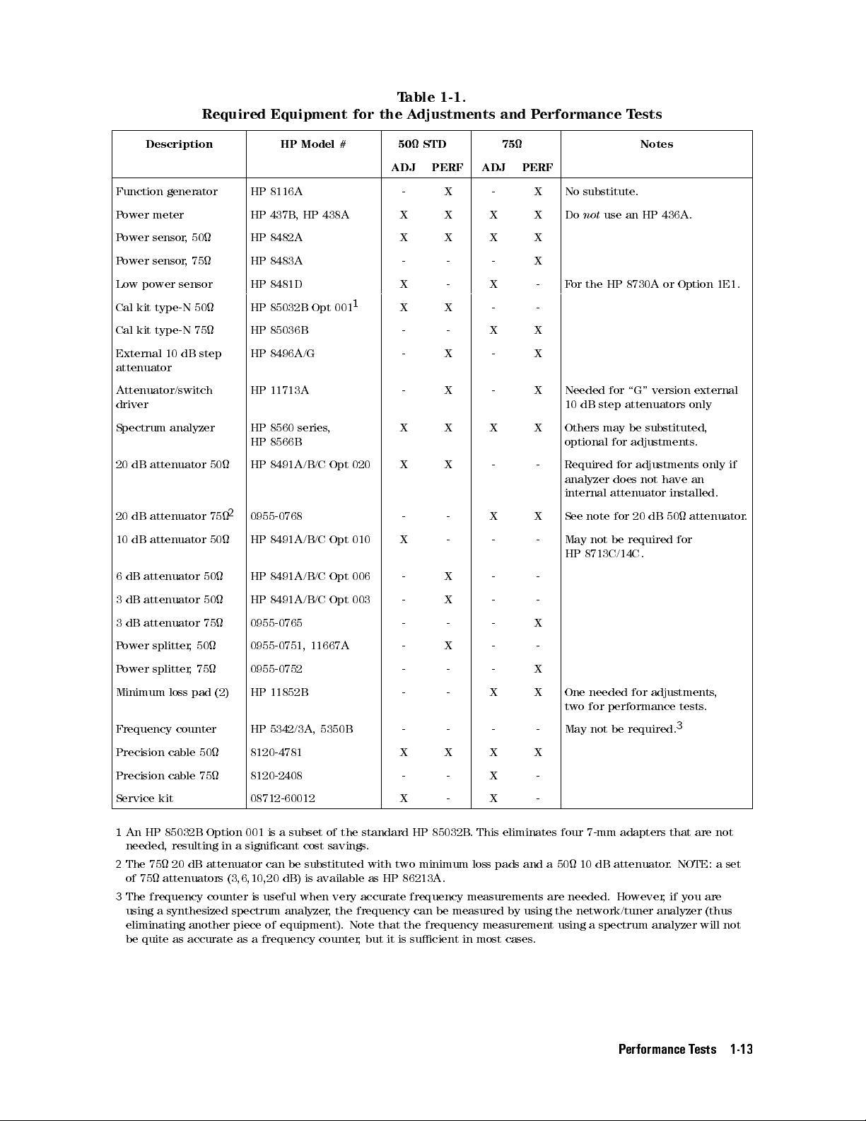
Required
Equipment for
T
the
able 1-1.
A
djustments
and
P
erformance
T
ests
Description HP
Function
Power
P
ower
P
ower
Low
Cal
Cal
External
meter
sensor
sensor
power
kit
kit
generator
sensor
type-N
type-N
10
dB
,
50
,
75
50
75
step
HP
8116A
HP 437B
HP
8482A
HP
8483A
HP
8481D
HP
85032B
HP
85036B
HP
8496A/G
Model
,
HP
Opt
438A
001
50
ADJ
-
STD
PERF
X
#
X X X X Do
X
X
1
X
X
-
-
-
X
-
-
-
X
75 Notes
ADJ
PERF
-
X
-
X
-
X
-
attenuator
Attenuator/switch
HP
11713A
-
X
-
driver
Spectrum
20
dB
attenuator
20
dB attenuator
10
dB
attenuator
6
dB
attenuator
3
dB
attenuator
3
dB
attenuator
P
ower splitter
P
ower splitter
Minimum
analyzer
50
50
75
,50
,75
loss pad
HP
8560
HP
HP
50
2
0955-0768 -
75
HP
50
HP
HP
series
8566B
8491A/B/C
8491A/B/C
8491A/B/C
8491A/B/C
0955-0765 -
0955-0751,
0955-0752 -
HP
(2)
11852B
Frequency counter HP 5342/3A,
Precision
cable
50
8120-4781 X
,
Opt
Opt
Opt
Opt
11667A
5350B
020
010
006
003
X
X
X
X
-
X
-
-
-
X
X
-
-
X
-
-
-
- - - - May not
X
X
-
X
-
-
-
-
-
-
X
X
Precision cable 75 8120-2408 - - X -
Service kit 08712-60012 X - X -
X
X
X
-
-
X
X
X
X
-
X
-
-
-
X
-
X
X
X
No
substitute.
not
F
or
the
Needed
10
dB
step
Others
optional
Required
analyzer
internal
See
note for
May
not
HP
8713C/14C
One
needed for
two for
use
an
HP
436A.
HP
8730A
or
Option
for
\G"
version
attenuators
may
be
substituted,
for
adjustments
for
adjustments
does
not
attenuator
be
have
20
dB
required
installed.
50
for
.
adjustments
performance tests
be
required.
3
1E1.
external
only
.
only
if
an
attenuator
,
.
.
1
An HP 85032B Option 001 is a
needed, resulting in a signicant cost savings
2
The 75 20
of 75
3
The frequency counter is useful when very accurate frequency measurements are needed. However
dB attenuator can be substituted with two minimum loss pads and a 50 10 dB attenuator
attenuators (3,6,10,20 dB) is available as HP 86213A.
subset of the standard HP 85032B
.
. This eliminates four 7-mm adapters that are not
. NOTE: a set
,ifyou
are
using a synthesized spectrum analyzer, the frequency can be measured by using the network/tuner analyzer (thus
eliminating another piece of equipment). Note that the frequency measurement using a spectrum analyzer will not
be quite as accurate as a frequency counter, but it is sucient in most cases.
Performance Tests 1-13
Page 30
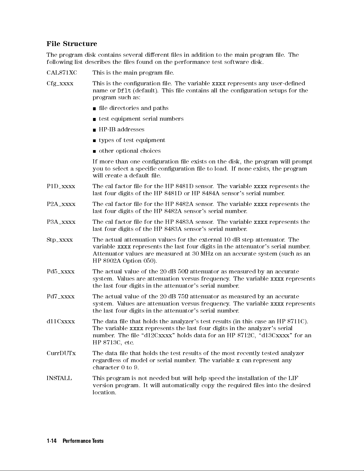
File
Structure
The
program
following
list
disk
contains
describes
the
several
les
found
dierent
on the
les
in
addition
performance test
to
the main
software disk.
program le
.The
CAL871XC
Cfg xxxx
P1D xxxx
P2A xxxx
P3A xxxx
Stp xxxx
This
is
the
This
is
the
name
or
Dflt
program
le
test
HP-IB
types
other
If
more
you
will
The
last
The
last
The
last
The
variable
such
directories
equipment
addresses
of
optional
than
to
select
create
cal
factor
four
digits
cal
factor
four
digits
cal
factor
four
digits
actual
xxxx
Attenuator
HP
8902A
main
program
conguration
(default).
as:
and
paths
serial
test
equipment
choices
one
conguration
a
specic
a
default
le
of
le
of
le
of
for
the
for
the
for
the
le
the
HP
the
HP
the
HP
attenuation
represents
values
Option
are
050).
le.
le
.
The
This
le
numbers
le
conguration
.
HP
8481D
8481D
HP
8482A
HP
8483A
values
the
measured
or
8482A
sensor's
8483A
sensor's
for
last
at
variable
contains
exists on
le
sensor
HP
8484A
sensor
sensor
the
external
four
digits
30
MHz
xxxx
represents any
all
the
conguration
the disk,
to
load.
.
The
variable
sensor's
.
The
variable
serial
number
.
The
variable
serial
number
10
in
the attenuator's
on
an accurate
If
dB
the
none
serial
.
.
step
user-dened
setups for
program
exists,
xxxx
the
represents
number
xxxx
represents
xxxx
represents the
attenuator
serial
system (such
will
prompt
program
.
.
The
number
as
the
the
the
.
an
Pd5 xxxx
Pd7 xxxx The
d11Cxxxx
CurrDUTx The data le that holds
The
actual
system.
the last
actual value
system. V
the last
The
data
The variable
number. The le
HP 8713C, etc
value
V
alues
are
four digits
alues are
four digits
le
that
xxxx
.
of
the
20 dB
attenuation
in the
of the
20 dB
50 attenuator
versus
attenuator's
75
attenuator
attenuation versus
in the
holds
represents
attenuator's serial
the
analyzer's
the last four digits in the analyzer's serial
\d12Cxxxx" holds data for an HP 8712C, \d13Cxxxx" for an
the test results of the most recently tested analyzer
regardless of model or serial number
as measured
frequency.
serial
number
as
measured
frequency.
number.
test
results
. The variable
by an
The variable
.
by
an
The
variable
(in this
x
case
an
can represent any
accurate
xxxx
accurate
xxxx
HP
represents
represents
8711C).
character 0 to 9.
INSTALL This program is not needed but will help speed the installation of the LIF
version program. It will automatically copy the required les into the desired
location.
1-14 Performance Tests
Page 31

Note
Several
default
The
values
sensor
for
the
only
to
will
access
message
data
les
les
that
in
these
cal
factors;
external
step attenuator
demonstrate
these
will
be
displayed
are
allow
le
20
les
present
operation
are
dB
for
or learn
if
no
if
on
the
disk with
of
the
nominal
the
20 dB
, and
values.
so on.
about the
user-dened
the
program
the \xxxx"
program with
For
NO correction
example: 100
attenuators; 10.00,
This is
program. The
serial number
is using
provided as
default conguration
is specied.
these default
sux. These
factors.
percent for
20.00, 30
..
a convenience
A warning
les.
are
all
.dB
le
Conguration
The conguration
specic information
the HP-IB
the HP-IB
the
model
the
serial
the
disk
other
Ideally
will
automatically
les
stored
prompt
performance
Getting
Caution
items
,
only
you
drive
Started
addresses of
address of
numbers
numbers
locations
specic
one
conguration le
on
the
to
select
test
software
Make
master
likelihood
File
(cong) le
for your
all the
the analyzer
of the
of
sensors,
(path
to
your setup
load
only
same
disk.
one
.
This
disk
a
copy
copy
of
is the
setup.
test
test
xed
and
that
le
In this
is useful
serves
of
the
should
damage
le
that
Some
equipment
under
equipment
attenuators
directories)
should exist
. However
case
,
if
several
performance
remain
to
the
customizes
of
the
test
on
,
it
the
program
more
than
workstations
stored
master
items
,
and
the
is
possible
test
in
disk.
this
contained
the
external
program
will
one
setup
.
software
a
safe
place
program
in
disk
to
have
list
all
is
commonly
disk
.
for
this
10
so
several
of
the
for
This
your
usage
le
include:
dB
step
that
the
conguration
available
used
day-to-day
will
decrease the
.
It
contains
attenuator
program
les
and
or
if
one
use
.
The
Note
The DOS
requires the
document assumes
it
is
First, nd all
serial numbers of the calibration devices required, such as external step
attenuators, sensors
the HP-IB addresses you
version, which
proper set
running
,
and xed attenuators for both 50 and 75 devices (if applicable). V
and
has
is used
up of
that users
been
properly
in
conjunction
the
HP-IB
are familiar
installed
with
interface
with HP
and congured.
HP
card
BASIC
B
and
ASIC
drivers
for
for
Windows
will be using, as well as the mass storage directories and locations
If you plan to operate this program only from the supplied oppy disk, insert the
computer's disk drive and skip step 1 next.
Performance Tests 1-15
Windows
.
This
|
,
that
erify
.
disk into the
Page 32

P
erformance
1.
To
install this
drive
,or
copy
all required
format).
Note
2.
Set
the
computer's
the
main
3.
Load
and
part
number
select
4.
Press
5.
Press
This
conguration
le's
the
N
N
N
N
N
N
N
RESUME
N
N
N
N
N
NN
CONFIG
menu allows
selection descriptions
T
est
program to
load and
The INST
program le
run
,
N
N
N
N
N
SET
NN
NN
N
N
N
N
N
N
N
N
N
N
N
N
N
N
run the
les to
ALL program
Any
directory name
less
than
this program.
revision
N
N
N
N
NN
NN
NN
N
N
N
N
N
N
TIME
N
N
N
N
.
Remember
N
N
N
N
to
enter
you to
(such as
Software
the hard
\INSTALL"
your specied
60
characters
\Mass
N
N
N
Storage
(CAL871XC).
The program
date and
N
N
softkey
,
the
the
conguration
enter all
test equipment,
and their
Installation
drive: either
program. The
destination drive
is only
current time/date
to
set
4
RETURN
contained in
used must
,
for
best
Is" (MSI)
will display
it.
5
key
screen.
the
specic
addresses
initial
copy all
INSTALL
the LIF
be
less
than
visibility
command to
can
information
default
.If
also
,
and
.
the
be
serial
values
les (except
program will
or directory
software version.
80
characters
the directory
the
initial
current
used
as
that
numbers).
are
listed
screen
time
softkey
pertains
below
\INST
ALL")
automatically
(HFS, SRM
long,
and
or drive
with
the
or
date
is
#1.
to
your
The
conguration
.
to
the
or LIF
preferably
location
software
incorrect,
particular
hard
of
Conguration
In
this
section,
The
analyzer's
Please
device
The
same
ISC
The
equipment.
The
for
Caution
The spectrum analyzer (HP 8566B) and address (18).
selection. Any of the listed models will suce
frequency counter
since it will be used as the frequency counter
The function generator model number (HP 8116A) and address (14).
for the function generator and address. The HP 8116A is the only valid selection at this time.
note
number
ISC
ISC).
to
7
ISC
power
the
power
does
or
for
Menu
the
default
HP-IB
that
this
associated
not
have
Generally
8
respectively
the
test
This
is
generally
meter
model
meter
The program will accept the HP 436A power
not recommended or supported and may cause the program to halt execution.
, then the spectrum analyzer must have high degree of frequency accuracy
values
address
is
the
to
the
full
.
equipment
model number
only
with
it.
be
the
address
The
factory
7
or
number
(716).
address
same
for
the
The
that
This
address
as
all
for
the
default
(7).
The
8 and
may be
(HP
437B) and
and address
parameters
rst
has
the
DUT
HP-IB
second selection
, but keep in mind that if you do not use a
.
listed
selection
both
the
can
be
any
other
test
is
set
to
device
the same
address (13).
.
in
bold
type
appear
is
the
analyzer
Interface
valid
address
equipment (which
either
as
Next is the spectrum analyzer
716
address for
is the
ISC
that
for
The next
meter as a valid selection, but it is
(DUT)
Select
Code
with
any
must be
or 816.
for
the
This also
the analyzer
all
the
DUT
.
two selections
The next selection is
in
parenthesis
HP-IB
(ISC)
associated
address
and
the
valid ISC.
all
on
sets
is 16.
are
the
test
.
.
the
1-16 Performance Tests
Page 33

The
attenuator switch
the
attenuator switch
are
the HP
manually
this
is inconvenient,
recommended.
The
frequency
model
spectrum
The
voltmeter
address
The
printer
all
HP-IB
except
re-direct
attached
The
program
program
location
the
disk).
should
here
characters
address
just
the
current
11713A
set the
number
analyzer
are
next,
address
printers
10
will
the
to
the
directory
of
the
If
you
be
blank.
(e
.g.
/TESTS/ANALYZER/NETWORK/8713C).
(preferably
of
the
drive
MSI
device
and
external
counter
and
its
to
model
they
should
direct
output
computer's
directory
and
CAL871XC
are
If using
disk
drive
letter
(for
.
driver model
driver
`NONE'.
10
the
use
model
address
measure
number
are
not
(01).
The
work
the
output
to
the
dened
parallel
and
Mass
Storage
program
running
an HFS
less
than 60
, also
example,
selection
If
`NONE'
dB
step
of
an
HP
number
are
next.
frequency
(HP
currently
printer
equally
to
the
Windows
the
mass
this
program
or
for easier
has
an
C:).
number
and
address
is
attenuator
11713A
(HP
If
`NONE'
accuracy
3456A)
used
address
well.
attached
port
or
a
storage
Unit
Specier
and
all
of
from
SRM
system,
80-character
When
(HP
11713A)
.
At
selected,
each
with
a
5342A)
is
.
and
address
by
this
is
next.
F
or
the
HP-IB
default
networked
its
viewing).
the
printer
unit
(MSUS)
required data
a oppy
the
The entire
limit.
program
this
time
the
program
time
it
HP
8496G
and
address
selected,
(22).
program.
No
model
DOS
version,
printer
.
printer
specier
are
disk, the
entire
The
F
or
is
and
address
,
the
only
will
needs
Typically
directory
MSUS,
the
rst
to
be
model
(02).
the
program
While
.
Selecting an
.
(the
next.
les (all
length
the
number
entering any
current
These
program directory
name
must
which
DOS
version,
run,
the
(28).
Next
two choices
prompt
changed. Since
attenuator is
The
voltmeter
this
the les
be
indicates
default
you to
frequency
will
use the
is needed
valid number
address of
will be
MSI
device).
should
contained
should
less
than
this
will
is
highly
counter
and
here;
10 will
a printer
point
to
entry
be
entered
80
the
physical
is
typically
be
the
The
the
on
The
data
directory
should
data
The
numbers
numbers
allows
The
contained
the
message
The step attenuator's 40 dB card selection (3).
section. The HP 8496G step attenuator contains one 10 dB section, one
40 dB sections
HP 8496G step attenuator is to be used; section 3 or 4. Enter the value (3 or 4) for which you
have calibration data.
For example, when the step attenuator was calibrated, one of the two 40 dB sections
was selected for the 40, 50, 60, and 70 dB attenuation value
the selected 40 dB section must be input to ensure valid measurement data when using
attenuations of 40 dB or greater.For purposes of identication, section 3 of the attenuator is
the section that is engaged when button #3 or #7 of the HP 11713A is lit.
This entry is not applicable if you are using a manual attenuator.
point
to
directory and
sensor's,
(xxxx).
for
the
the
program
disk
contains
within
program
to
will
be
. This step species which of the two 40 dB
and
the
location
MSUS
external
Six
power
to
les
these
be
run
displayed
MSUS
.
where
are
otherwise
10
dB
step
of
the
next
meter
load
that
les
for
sensors
the
proper
match
is
invalid
experimental or
if
a
default le
The
next
the
results
similar
attenuator's
seven
entries
,
the
correction
these
default
(e
.g.
two
entries
of
to
will
step
attenuator
serial
100
percent
training purposes
is
loaded.
are
each
DUT
the
program
,
and
xed
contain
values
numbers
for
One of the
the
data
directory
will
be
stored
directory
attenuator's
the
LAST
FOUR
,
and
the
20
dB
for
each
device
(xxxx),
all
sensor
only.
next selections is the 40 dB step
attenuator card sections of the
. The data corresponding to
cal
As a
and
MSUS.
(if
applicable).
,
including
(pad's)
digits
attenuators
.
but
the
factors).
precaution, a
20 dB section, and two
the
serial
of the
correction
This
These
The
defaults
serial
. This
data
allows
warning
.
Performance Tests 1-17
Page 34

The
beeper (on).
The
current DUT
current
users
can
6.
7.
device under
to operate
be ignored
Once
data
just
conguration
\Cfg dt."
If
more
choose
After
values
3
sensors
an
external
two
Y
ou
will
list
that
all
than
one
the
must
20
need to
you
from
for
desired
entered.
is
If
the
one
.
At
cong
be
10
dB
attenuators
will be
The last
le
single-user
changes
required.
is
this
le
generated.
dB
enter the
selection
sux
test.
Up
one
system
A
specic
program
discovered,
point
has
been
step
using to
will
(1).
This
le
to
ten
dierent
storage
applications
have
been
made
4-character
Leaving
nds
the
Press
attenuator
(pads)
correction data
the
only
the
program
program
generated,
NN
N
N
N
N
N
N
N
CAL
test the
suppress
,
\CurrDUTx,"
le
medium,
.
,
the
le
name
le
name
one
cong
will
will
also
the
N
N
N
N
N
DATA
analyzer.
proper
N
N
N
N
N
N
N
NN
NN
NN
N
N
N
ENTRY
for
or
enable
names
such
program
blank
le
list
ask you
N
N
N
N
N
N
N
N
N
N
N
N
N
N
every
Select
contains
can
as
sux
,
that
the
data
.
Y
ou
piece
the
the
beeper
the
be
specied.
an
SRM
environment.
will
ask
if
can
be
provided
will
result
in
le
will
be
le
names
if a
hardcopy printout
les
containing the
will
be
shown
of
test
equipment
desired
item.
,
as
desired.
test-result
you want
the
loaded automatically
found
data
This
allows multiple
This
to store
if
more
default
and allow
is desired.
correction
a
list
including:
included
of the
than one
le
entry
the
name of
.
you to
in
this
Sensors
be
the
information.
Assuming you
This
After
entered.
enter
the
must
percent.
negative
factor
will
Each
entry portion of the program. At this point the program will re-display all values entered and
ask if you want to store them.
Note
20 dB Attenuators (P
described is used to enter the frequency/attenuation values for
entries for the 20 dB attenuator range from 17.5 to 23.5 dB.
.
All
sensors
in
MHz
and
serial number
If
value must
the
cal
factor
Y
ou
must
higher
cal
be
be
entry
factor
higher
If
a
frequency
pair),
the
a
\?".
is
frequencies
mistake
shown
require
cal
factors in
.
The
computer
one
is
present,
are
editing
use
start
in
percent,
than
.
computer
Even if
re-edit the values
the
percent
is
entered,
with
until
separated
the
previous
is
made
If
you
accidentally
will
on
the
you nd a mistake
ads).
both frequency
percent. The
will
search
the
program
data,
the
as
its
units
the
program
the
lowest
done
.
Each
by
entry
,
you
can
wait
for
CRT
. When
, otherwise you will have to re-enter all values again.
A procedure similar to the sensor data entry procedure previously
and cal
rst
for
will
50
MHz
and
be
will
frequency
entry
a
comma
.
These
back
up
enter
only
the
cal
all
entries
, it will be easier to answer yes
factor
entry
requested
a
current
query
reference
within
request
for
must
consist
(e
.g.
500,
cal
factor
one
entry
the
factor
to be
are
completed,
data.
will
conguration
you
to
either
cal
factor
the
range
of
that
all
frequency/cal
which
frequency
you
of
both
98.6).
values
and
must
re-enter
entered; however
the 20 dB attenuators
Frequencies
be
the
last
le
view
or
will
be
requested
50
and
150
have
data
a
frequency
Each
frequency
be
between
a
value
(instead of
enter
\0,0"
, then go back and
must
always
four
digits
containing
edit
percent.
factor
and
by
a frequency/cal
the only
to
exit
this
the
old
next.
pairs
sequentially
in
MHz
entered
75
and 125
entering a
prompt
the
.V
alid
of
values
be
and
data
.
External 10 dB Step Attenuator.
one value needs to be entered for each nominal attenuation step. All values are relative to the
0 dB setting, which is dened as zero (i.e. the program does not care about insertion loss at the
0 dB setting).
1-18 Performance Tests
Step attenuator data is only measured at 30 MHz so only
Page 35

V
alid entries
up
to 110
are within
dB
of
3
dB
attenuation.
of
the
nominal
attenuation
setting.
The
program
will
request
data
Using
Note
When the
program name
with
N
N
N
N
NN
SET
will
N
N
N
N
N
HELP
N
N
N
N
N
EXIT
N
N
N
N
N
RESUME
Main
The
returning
N
N
N
NN
CONFIG
HP-IB
N
N
NN
N
LOAD
available
are
N
N
N
N
N
CAL
attenuators
N
N
N
N
N
PRINT
previously
correct
N
N
N
N
N
NEW
before
the Program
program is
four
softkey
NN
NN
N
N
N
N
N
N
N
N
N
N
N
N
N
N
N
N
TIME
allows you
force
you
N
N
N
N
N
N
N
N
N
will
present
N
N
N
N
N
N
N
N
N
will
terminate
N
N
N
N
N
N
NN
NN
NN
N
N
N
will
Menu
main
menu
to
this
N
N
N
N
N
N
N
N
N
N
N
N
N
N
N
allows
addresses
N
N
N
N
N
N
N
N
N
N
N
N
N
N
N
N
N
N
N
N
N
N
NN
N
N
CONFIG
instructed
N
N
N
N
N
N
N
N
N
N
N
DATA
N
N
N
N
N
N
N
N
N
N
NN
N
N
N
N
N
NN
NN
NN
DUT
N
,
it
is
N
N
NN
NN
N
N
N
N
N
N
N
N
N
N
ENTRY
.
NN
NN
N
N
N
N
N
N
N
N
N
N
N
RESULTS
tested
any
header information
NN
NN
NN
N
will
you begin to test another analyzer
Remember
rst run,
, revision
to
enter
continue
provides
menu
you
.
N
N
N
allows
automatically
to
select
N
N
N
N
N
N
N
N
N
N
N
N
See
\Conguration File
N
N
N
N
N
N
N
N
N
allows
appear
number,
choices:
to set
it
some
the
execution
from
to
dene
This
selection
you
one
allows
you
analyzer
only
regardless
very
program.
seven
you
,
that
the
the initial
N
N
N
N
N
NN
NN
NN
NN
N
RESUME
the time
brief
softkey
the
a
particular
is
to
select
loaded
.
to
to
print
assuming
that was
after an
4
RETURN
date and
N
N
N
N
N
NN
N
of
test
enter
NN
N
N
N
N
N
SET
,
and
of
whether
instructions
the
program
selection
described
one
of
without
correction
," earlier
or
view
the
analyzer
5
/
4
information
other
NN
NN
N
N
N
N
N
N
N
N
TIME
date
choices
conguration
earlier
several
further
test
data
previously entered.
has
.
5
/
4
ENTER
N
N
N
N
N
.
.
menu.
in this
was
EXECUTE
screen
miscellaneous
N
N
N
N
N
NN
NN
NN
NN
HELP
,
If
the
or
not this
and
other
and proceed
An
eighth
in
congurations
conrmation.
factors
chapter.
results
archived.
been
N
,
and
date
of
\Conguration
tested.
5
key
is
presented.
information.
N
N
N
N
N
NN
NN
NN
NN
N
EXIT
.
has
never
softkey is
information.
to the
choice
test
for
from
may
equipment,
to
sensors
the current
Y
ou can
This
can
be
used as
This
Y
ou
been
set,
pressed.
main menu.
be
displayed
mass
File
."
choose
If
,
softkey
from.
several
attenuators and
also add
are
DUT or
must
softkey #1.
contains
are
the
storage
If
available
comments or
be
the
presented
program
if
you
,
and
only
any
selected
one
,
are
is
you
Note
NNNNNNNNNNNNNNNNNN
HP-IB Addr's
addition it will allow you to check each listed address for the presence of an active device
will not indicate which device is set to which address. It only indicates whether or not the
device at a given address is capable of handshaking properly.
menu.
NNNNNNNNNNNNNNNNNNNN
RESUME
the power is switched ON and the HP-IB cable is connected before pressing
NNNNNNNNNNNNNNNNNNNN
will continue the program and look for an analyzer at the specied address. Make sure
This is the only way that the program can tell that the analyzer under test has
changed. Once selected, this softkey selection will disappear
the program is ready to search
will display the current expected addresses of all
for a new analyzer model/serial number
required test equipment. In
NNNNNNNNNNNNNN
EXIT
returns to the previous
, indicating that
.
NNNNNNNNNNNNNNNNNNNN
RESUME
Performance Tests 1-19
.
.
It
Page 36

Once
the program
for
any previous
allowed
order
T
est Selection
The
to enter
, comments
test
selection
nds the
test
results
any
pertinent
etc
.
The
Menu
menu
test
can
analyzer
.
If
none
data
selection
be
divided
,
the
serial
are
found,
regarding
menu
into
number
this
is
four
a
message
new
then
main
is
interrogated
is
displayed
DUT
such
presented.
categories:
as
and
and you
owner
the
disk
is
searched
are then
,
technician, repair
Eleven
One
automated
F
our
utility
Two
detector
Data
for
stored
The
1.
Caution
2.
3.
for
four
N
N
N
N
N
N
N
N
N
N
N
N
N
Set
Serial
be
required
N
N
NN
Step
The
the
mechanical
Option
resulting
performed
user
.
to
ten
variances
for
signs
N
N
N
N
N
N
N
N
N
N
N
N
N
Measure
measure
as
a
last
be
measured using
automated
procedures
each
of
the
one
utility
N
N
N
N
N
N
N
NN
N
N
N
N
N
N
N
N
N
after
N
N
N
N
N
N
N
N
N
N
N
N
N
N
N
N
Attenuator
1E1
units
trace
at
A
minimum
minutes
of
of
wear
N
N
N
N
N
N
NN
NN
NN
N
N
N
N
N
N
Step
the
resort
analyzer
adjustment
performance
the
eleven
adjustment
programs
N
N
N
N
N
N
N
N
N
N
N
N
N
N
NN
N
N
N
N
N
Number
Enter
entered.
center
N
N
N
N
N
N
a
more
N
N
N
N
N
N
actual
N
utility
some
the
If
for correction.
N
NN
N
N
N
N
N
N
N
N
N
N
N
N
N
N
N
N
N
(and
therefore
only).
measured.
low
frequency
of
twenty-ve
depending
than
.
N
N
N
N
N
N
N
NN
NN
NN
N
N
N
N
N
N
Attenuator
if
N
insertion
no other
one of
performance
procedure
tests
(HP
performance
routine
are
described
allows
types
of
number
a
N
N
N
N
N
N
Test
F
0.1
N
N
N
N
N
N
carefully
mistake
NN
N
N
N
N
N
N
N
N
is
,
electrical)
or
each
Minimum
and
upon
computer
dB
should warrant
N
N
N
N
N
N
NN
(external)
loss
method of
the following
tests
86200B
tests
.
as
follows:
you
to
repairs.
;
it
is
made
,
a
cyclical
cycle
a
is
recommended.
at 30
stress
integrity
,
the
and
maximum
high
frequency
speed.
is
a
MHz for
obtaining data
methods:
or
HP
86201B)
is
archived
enter
a
cannot
it
will
test
attenuator
further investigation
utility
this device
upon
serial
number
be easily
be necessary
designed
of
the
built-in
card
excursions
.
The
One hundred
There
is no
le
designed
is available
completion.
into
the
changed once
to contact
to
show
any
attenuator
is
switched
are
then
noted.
number
. This
of
cycles
cycles will
pass/fail indication
or increased
to
use
a
routine
.
Generally
No archive
analyzer
it has
an
HP
weakness
(HP
in
and out
The
is
selected
take
power
should
the
data is
.
This
been
service
in
8730A
with
test
by the
about
but
trace
monitoring
meter
device
only
to
be
should
may
or
each
is
ve
used
Sending the device to a calibration standards lab
Measuring the device with an HP 8753D with full two-port correction
Measuring the device with an HP 8902A Option 050
NNNNNNNNNNNNNNNNNNNN
4.
Measure 20 dB Pad
Note
The detector perfomance tests consists of an absolute power accuracy test and a frequency
response test as described in the
These tests are only for testing these two specic detector models. Archiving of data is not
done for these tests.
1-20 Performance Tests
NNNNNNNNNNNNNNNNNNNNNNNNN
NNNNNNNN
is identical to the
The listed uncertainties shown on the test results assume that one of these
three choices was used and
degree of uncertainty.
HP 86200B/86201B RF Detectors User's and Service Guide
NNNNNNNNNNNNNNNNNNNN
Measure Step Attenuator
not
NNNNNNNNNNNNNNNNNNNNNNNNN
the built-in routine which has a much higher
NNNNNNNNNNNNNNNNNNNNNNNNN
N
utility.
.
Page 37

Miscellaneous
The
program gives
some
of the
connection
a
direct connection
and
switched ON
write
to
the
program
30
seconds
reset
and
required
lines between
a
device
will
for
the
program
Information
full
step
adapters
(adapters
before
before
time-out
all
devices
proceeding
it
.
run
by
step
may
devices
may
is
shown
before
If
the
again
instructions
not
be
indicate
be
required).
with
in
the
the
connection
program
with
little
along
depicted
a
cable
All
any
test,
connection
diagram
should
or
no
loss
with
in
the
connection
connection,
required
since
the
diagram.
is
stop
for
any
of
data
connection
where
equipment
program
If
the
drawn.
(if
The
reason,
a
SCRATCH
diagrams
diagrams
as
a
should
will
device is
time-out
the computer
.
.
dotted
be
occasionally
not connected,
C
is
not
F
or clarity
Generally,
line
indicates
connected
need
limit
is
set to
may be
performed).
,
solid
to
Individual
The
following
them
manually
tests
,
turn
on the
Note
Frequency
This
test
measures
in
trigger-hold
counter
A
ccuracy
analyzers
or
If
F
ailures
crystal
amount,
suspect
the
or
spectrum
This
T
est
of
oscillator
and
excessive
A4
Source
a
is
(75)
this
T
est
sections
without
analyzer and
F
or
This
N
N
N
N
N
N
N
N
Next
A
ccuracy
the
mode
spectrum
measured
will
analyzer
F
ails
test
by
the
A3
noise
Assembly"
Notes
the HP
is
N
N
N
N
NN
NN
.
require
.
are
performing
fractional-N/reference
and
explain
a
computer
8730A,
done
by
NN
Menu
The
analyzer
to
N
N
N
N
N
N
N
N
N
N
N
N
,
frequency
device
.005
a
rare
.
If
on
the
in
the
Descriptions
how
each
.
Before
allow it
it
is
pressing
N
N
N
N
N
N
N
N
N
N
N
NN
NN
NN
N
N
N
N
Next
with
percent
minimum
this
the
RF
N
Menu
accuracy
used
a
or
test
frequency
output
\Troubleshooting
test
running or
to
warm
necessary
4
SYSTEM
N
N
N
N
N
N
N
N
N
N
N
N
Inst
,
measure
5
kHz
loss
should
of
N
of
degree
pad
assembly's
the source
N
to
high
is performed,
manually performing
up
for
one
to
precede
OPTIONS
N
N
N
N
NN
NN
NN
N
N
State
the
analyzer
at
1000
in
fail
accuracy
5
N
N
N
N
N
N
N
N
N
N
N
N
N
N
N
N
N
Utilities
the
frequency
of
frequency
MHz.
order
to
by
a small
adjustment.
10
.See
and
Block Diagrams"
in case
hour
N
N
N
N
N
Service
,
NN
NN
NN
N
N
at
connect
MHz
the section
it is
.
each
test
N
N
NN
N
N
N
N
N
N
N
N
N
N
N
N
N
N
N
N
N
N
N
N
N
N
N
N
N
N
N
N
N
N
N
,
several
can
accuracy
The
HP
amount, readjust
reference output
necessary
with
N
N
N
N
N
N
N
NN
N
N
N
N
N
Service
,
N
N
N
N
N
N
N
N
N
N
N
N
NN
NN
Preset
CW
frequencies
either
.
8730A
to
a
50
If it
fails by
titled \Troubleshooting
chapter.
to
perform
the performance
a
service
N
N
N
N
N
N
N
N
N
N
N
N
N
N
N
N
N
N
NN
N
N
N
N
N
Utilities
NN
N
N
N
N
N
N
N
N
N
N
N
N
N
N
N
N
N
N
N
NN
to
be
and
frequency
NN
8711C
a
frequency
Option
the reference
a signicant
is accurate
preset.
N
N
N
N
N
N
N
N
N
N
N
N
N
NN
N
N
N
N
.
while
1EC
counter
N
,
,
Gain
Compression
Gain compression is measured over the frequency range by inserting a calibrated 20 dB
xed attenuator and measuring the change with the analyzer
through-line cable is rst connected to the ports and the power level set to 3 dBm for the
HP 8713C/14C or +13 dBm (or max power) for the HP 8711C/12C/30A. The 3 dB attenuator
is used to improve any mismatch errors
calibrated 20 dB xed attenuator is then
measured again. The dierence is then compared to
20 dB xed attenuator
.
. The resulting power is read by the analyzer
inserted into the path and the resulting power is
the known insertion loss of the calibrated
. A 3 dB xed attenuator and
. The
Performance Tests 1-21
Page 38

The
power levels
characteristics
to
0
20
dBm
power
the
If
This T
+10 to
est
0
F
of the
10
ails
dBm
tested for
receiver
range
.
power
both
high
.
Gain
Likewise
range
and
low
compression
,
gain
compression
.
Compression
frequency
for
the
for
is
tested
units
HP
8713C/14C
the
HP
in
a
are
based
8711C/12C/30A is
narrow (250
on
is
tested
known
in
the 0
tested in
Hz) bandwidth.
dBm
Repeat
assembly
Noise
The
the
portion,
W
noise
activated.
frequencies
If
First
only
the
information.
either
Dynamic
Dynamic
from
attenuator
be
to
all
20
from
attenuator
adjustments
.
Floor
noise
oor
RF
output
the
analyzer
orst-case
This
A5
used to
measure the
measurements are
dB).
oor
T
est
verify
the
broadband
Receiver
the
accuracy
0
dBm
The
the
analyzer
.
noise
is
measured
This
above
F
ails
that
Otherwise
A3
A
ccuracy
(if
is
used
convert
attenuator
The
#101
and
#105.
test
is
divided
is
terminated
is
oor
portion
5
MHz.
all
cable
portion
Assembly"
fractional-N/reference or
is
measured
possible)
as
the
the
B
input
made
.
These
dierence
in
set
to
measure
is
then
measured
with
the
of
the
connections
fails
in
,
the A5
down
reference
impedance
in
a
ne
relative
is
then
values
is
the
If
into
two
50
or
B
input
test
is
divided
,
the
the
\Troubleshooting
receiver assembly
on
the
to
0
100
device
to
(15
Hz)
to
switched
are
then
dynamic
this
does
sections;
75
and
B*
with
starting
(not
B/R)
into
and
screws
A5
receiver
A4 source
narrowband
dBm
in
.
On
50
for
the
bandwidth.
this
point
in
10
dB
compared
accuracy
not
solve
broadband
the RF
averaging
from
10
in
a
two
are
secure,
diodes may
and
is
most
assemblies
B
detector
10
dB
increments
75
analyzers
HP
8496A/G
P
ower
(generally
increments
to
error
the
problem,
and
narrowband.
input is
ne bandwidth
sections:
the
shorted. F
ON
and
with a
MHz.
F
or narrowband
frequencies
then repeat
be bad;
Block
Diagrams" chapter
likely
bad,
can
also
at
a
CW
.
A
,
two
minimum
attenuator
is
rst
measured
this
means
and
the
known
of
the
values
analyzer
replace
or the
(15 Hz)
see \Troubleshooting
though
cause
frequency
calibrated
.
the
resulting
.
the
A5 receiver
During
narrow bandwidth.
and spur
below 5
adjustment #102.
spurs
noise
loss
The
analyzer
at
attenuator
power is
of
the
this
broadband
mode,
10
0
the
MHz and
for more
generated
oor
of
30
dB
step
pads
must
20
dBm
is
calibrated
test
avoid
If
failures
MHz,
is
set
and
set
to
read
step
in
.
Mismatch
combinations
only
If This T
First repeat adjustment #102. If the problem persists
attenuator used to perform this adjustment; see \The 40 dB step attenuator
in \Performance T
test; verify that all cables and screws are secure
1-22 Performance Tests
levels
est F
errors
of
at
and
ails
are
minimal
options
below
est Software Installation" earlier in this chapter
on
75
0
10 dBm
since
analyzers
the
input/output
,
the
are tested.
0
match
dBm
.
at
point
may
, suspect calibration errors
30
MHz
is
very
not
be
obtainable
. Crosstalk can also aect this
good.
card selection (3)"
F
or
some
.
In this
in the step
case,
Page 39

P
ower Flatness
P
ower atness
the
frequency range
2
dB is
allowed.
The
analyzer is
measured
compared
specied
applicable).
section
any
A
second
cable
1601
any
test.
verify
If
This
and corrected
to
the
power
If
of
the
series
of
test
is
connected
points-per-sweep
signicant
The
sweep
its
power
T
est
F
ails
is
dened
In
stepped
specication.
to
the
analyzer
attenuator
measurements
is
performed
power
is
atness
as
of
the
this
test
through
based
the
minimum
(10
and,
starting
.
The
holes
repeated
.
the
maximum
analyzer
a
calibrated
twenty-seven
on
Several
specied
has
an
dB
,
20
below
as
a
precaution
at
B*
input
that
could
again
.
If
the
power
the
power
power
power
attenuator
dB
,
and
0
19
dBm.
10
MHz,
is
also
have
using
each
variation
specication
sensor
CW
frequencies
sensor
levels
without
,
three
30
dB).
to
ensure
the
analyzer
measured
been
missed
section
in
power
is
is
connected
cal
factor
are
tested,
using
more
levels
The
power meter
that no
is
and
during
of
the
at
the
6
1
dB
then a
at
one
.
The
ranging
the
are
power holes
swept
the
over its
resulting
the
attenuator
RF
output connector
maximum variation
directly
maximum
built
tested,
previous
to the
power
is zeroed
level
variation
from
the
in
attenuator
each
exist. A
frequency range
trace is
section of
(if one
is installed)
across
RF output.
and
each
is
is then
maximum
(if
one using
before making
through
checked for
one
using
this
to
of
Repeat
adjustment
Absolute
This
down
source
An
The
the
attenuator
resulting
on
this
(or
the
level
recorded.
These
compared to the specication. A narrow bandwidth is used for all
75 analyzers
If This T
the
test,
#104.
P
ower
test
veries
to
0
50
dBm
is
required
external
output
attenuator and
the
would
calculated)
output
conditions
10
of
the
are varied
power is
step
attenuator
be
acceptable
using
of
the
measurements
, the 6 dB attenuator is replaced with a
est F
ails
verifying
Accuracy
the
accuracy
(
0
47
to
achieve
dB
step
HP
8116A
a
power
in
noted.
the
attenuator
are
then
are
that
of the
dBm
for
the
attenuator
is
sensor
5
dB
increments
F
or
measurements
values
.
,
it
is
an
power
is
repeated
compared
all
connections
B*
input
the
HP
8730A
required power
is
used
to
sent
to
the
is
then
from
This
avoids
inconvenience).
meter
connected
and
to
as
a
to
the
the
power meter
are
secure
at
30
and
(in
vary
output
step
attenuator
connected
+16
below
having
reference
resulting
the
to
Once
RF
.If
the test
MHz
from
its
Option
this
down
0
use
,
input
analyzer
1EC
analyzers).
case
an
power
.
to
the
to
24
dBm,
a
the
the
power
of
readings
minimum loss pad.
over
A
6
dB
attenuator
approximately
the
low-power
power
sensor
the
measurements
still fails
maximum
HP
8116A
the
attenuator
.
power
diode
levels
analyzer
and
any
analyzer measurements
,
repeat
input
A
separate
function
full
66
dB
is
placed
The
source
0
24
dBm
out
is
calculated
sensor (although
have
been
is
disconnected
.
The
same power
are
averaged
deviations
of
range
and
measured
+16
dBm
power
generator).
.
after
step
and
the
based
and
and
are
.For
First verify that the correct 40 dB section of the attenuator is being used (if applicable). See
\The step attenuator's 40 dB card selection (3)" in \P
earlier in this chapter
If this is okay, repeat adjustment #110. If the test still fails, the cause is most likely damaged
A5 receiver diodes. See \Troubleshooting the A5 Receiver Assembly" in the \Troubleshooting
and Block Diagrams" chapter for more information.
.
erformance T
est Software Installation"
Performance Tests 1-23
Page 40

Broadband
This
test checks
to
the analyzer
output
to
analyzer's
been
process
for
averaged
V
sensor
necessary
the
used
If
of the
the other
source power
done
,
is
repeated.
each
frequency
power
ariations
unused
This
in
must
,
three-way
interchangeably
T
est
Frequency Response
the
.
The
splitter
output.
the
two
meter
response
also
port
is
F
ails
broadband
RF
output
is
sent
The
connections
This
point
data.
are
have
a
75
power
terminated
with
analyzer
and
are
frequency
of
to
the
the
eliminates
averaged
Both
then
relative
input
splitters
in
minimal
the
analyzer
RF
input
is
stepped
corrected
to
the
outputs
any
and
sets
of
to
impedance
can
its
characteristic
measurement
response
is
sent
of
the
through
power
of
dierences
the
averaged
data
are
this
point.
.
A
dapters are
be
substituted
degradation.
of
the
to
the
analyzer
a
cycle
meter
the
impedance
reading
power
within
analyzer
subtracted
F
or
75
for
B*
input
at
a
nominal
input of
while
of
splitter
the
power
from
analyzers
generally required
two-way
.
P
a power
CW
frequencies
are
noted.
are
data
a
ower
apower
swapped, and
splitter
is
30
MHz
the power
power
dividers or
0
6
splitter.
sensor is
while the
Once
this
.
The
two
compared
reference point.
splitters
to
splitter and
for this
,as
splitters can
dBm input
One
connected
has
the
readings
the
test. If
long as
be
Repeat
adjustment
properly
Diagrams"
Directivity
These
an
Note
Directivity
RF
calibration
provide
calibration.
the
Source
with the
1.
the
test
after
verifying
for
this
test.
.
See
\Troubleshooting
chapter
tests
require
HP
85036B
is
output
test
To disable correction, press
NNNNNNN
Meas Cal Options
and
of
40
dB
The
and
displays
match
following steps:
NNNNNNNNNNNNNNNNNNNNNNNNN
for
(includes
an HP
calibration
The
standard
components to
measured
performing
the
analyzer
of
directivity
typical
the
is measured
NNNNNNNNNNNNNNNNNN
that
all
V
erify
that
the
the
A5
more
information.
source
85032B calibration
kit
by
.
specication
results
NNNNNNN
Meas Cal on OFF
match, test
for a
75
economy
perform
presetting
a
reection
This
value
,
but
for
on
at the
NNNNNNNNNNNNNNNNNNNNNNNNN
same time
4
SYSTEM
the
this
is
the
NNNNNNNNNNNNNNN
connections
A5
receiver
Receiver
analyzer
(E)
versions
this
procedure
analyzer
measurement.
is
characteristically 30
test,
30
dB
screen
as directivity
OPTIONS
.
are
assembly's
Assembly"
port match,
kit
(standard
.
of
these
.
,
then
This
we are
.
The
of
5
testing only
program
the analyzer
N
N
N
N
N
N
N
N
N
NN
N
N
N
N
N
Service
secure
.
There
in
the \Troubleshooting
and
or
Option
kits do
attaching
measures
dB.
prompts you
.
.
This
test
N
N
N
N
N
N
N
N
N
NN
N
N
N
N
N
N
N
N
N
Service Utilities
is
detector
reection
001)
not
a
known-good
the
A user
the quality
can
N
N
N
N
N
N
N
N
N
NN
N
N
N
N
N
no
corresponding
diodes
provide
default reection
calibration will
through all
be
N
N
N
N
N
NN
N
N
are
tracking)
for
a
50
the
load
of
the
performed
N
N
N
N
N
N
N
N
N
NN
N
N
N
N
functioning
and Block
analyzer
necessary
to
default
portions of
manually
or
the
2. P
erform a one-port reection calibration.
NNNNNN
3.
To view the source match array
(Raw directivity can also be viewed by selecting
the default directivity above; raw directivity will be much lower
Input port match is measured by performing a one-port calibration at the end of a type-N cable
using the female standards contained in the cal kit. For this reason, the economy version of the
cal kits cannot be used since they do not contain female standards. Once the user calibration is
completed, the cable is attached to the RF input port and the input match is measured. Please
note that when the female open is called for during this user calibration, the extender pin must
be placed over the center conductor of the cable.
1-24 Performance Tests
, press
NNNNNNNNNNNNNNNNNNNNNNNNN
View Array Master
NNNNNNNNNNNNNNNNNNNNNN
NNNNNNNNNNNNNNNNNNNNN
Directivity
NNNNNN
NNNNNNNNNNNNNNNNNNNNNNNNN
Source Match
NNNNNNNNNNNNNN
. Do not confuse this with
.)
NNNNNNN
.
Page 41

Reection
tracking is
measurement.
measurement
If
This T
est
F
After a
of a
ails
determined from
one-port
male
short
is
the
reection
made
.
frequency
calibration
response
has
been
of
a
corrected
performed,
reection
a
reection
Directivity
the
quality
the
quality
the
quality
If
directivity
loss).
Source
failures
T
est
fail,
match
It
repeat
Spurs
is
port
rst
fails
very
will
adjustment
(including
Harmonics
quality
to
+7
50.
dBm
4
dB
3
dB
type-N
The
for
for
is mostly
of
adjustment
of
reference
the
load
fails
,
repeat
match
is
probably
match
inspect
unlikely
,
also
is
solely
the
suspect
that
#107
harmonics)
and
spurs
cable
.F
loss
through
minus
the
sum
the
HP
8730A
HP
8711C/12C13C/14C
dependent
#107
load
used
in
adjustment
mostly
require
dependent
two
type-N
the
A5
reection
with
a
are tested
or 75
the cable
of:
upon:
used
in
the
the
test
#107
dependent
the
replacement
upon
connectors
receiver
tracking
known
good
by connecting
analyzers
,
is
compensated
Option
adjustment
with
upon
hardware
of
the
A5
for
assembly
will
fail.
load
the
a
minimum
1EC
(75
a
known
the
A5
receiver
damage
diodes
However
(better
analyzer
loss
for
)
good load
in
the
A5 receiver
receiver
assembly
assembly
,
especially
.
,
if
reection
than
40
dB
to
a
spectrum
pad
is
used
automatically
(better than
.
.If
either of
on
75 units
tracking
of
return
analyzer
to
change
.
Harmonics
40 dB
assembly.
these two
.If
the test
does
loss).
via
the
impedance
are
of return
Any
fail,
a
high
tested
tests
port
at
1
dB for
2
dB for
4
dB
In-band
not
be
harmonics
Fractional-N
but
generally
specications only
HP
HP
for
HP
harmonics
tested
on
are
spurs
none
8711C/12C13C/14C
8711C/12C
8713C/14C
are
an
not
tested.
are
of
Option
Option
tested
HP
also
these
at
8711C/12C/30A
tested
cause problems
.
Option
1D
A/1DB
1D
A/1DB
several
with
1E1
(step
(AM
delay)
(AM
delay)
frequencies
because
its
this program,
.
These
attenuator)
.
The
second
upper
frequency
as well
type
of
spurs
harmonic
as some
have
of
is
1300
MHz.
other types
typical
700
MHz
need
Out-of-band
of spurs
(characteristic)
This automated test requires that the spectrum analyzer's and the network/tuner analyzer's
timebases be tied together
, so that any known spur will be
at the exact frequency expected.
Connect a BNC cable between the spectrum analyzer's EXT REF OUT to the network/tuner
analyzer's EXT REF IN. This saves signicant time since the program does not have to search
for every signal. The program will rst check that the timebases are connected together
before proceeding. If this test is performed manually
, locking the two analyzers together is not
necessary.
If This Test Fails
Note that while many types of spurs are tested, only harmonics are specied. If harmonics
should fail, repeat the fractional-N adjustment as well as adjustment #104. The most likely
cause of a failure is the A4 source assembly.
Performance Tests 1-25
Page 42

AM
Delay Modulator
AM
delay itself
However
CW
on
either side
the
at
several
matching
analyzer
If
This
The
that
replace
the AM
signal is
AM
sidebands to
CW
is
needed.
timebases
T
est
F
AM
delay
the
ribbon
the
AM
is
not
delay
modulated
of
the
CW
be
between
frequencies
As
should
ails
adjustment
cable
delay
(Option 1D
tested
in
modulator
with
signal
22.5
.
F
or
discussed
be
connected
does
is
securely
modulator
A/1DB
the
analyzer
is
tested
a
27.78
when
and
75
analyzers
previously
not
signicantly
attached
assembly
kHz
viewed
33
dB
together
to
.
analyzers
since
it
for
functionality
sinewave
on
a
spectrum
below
,
a
minimum
,
the
spectrum
to
aect
the
AM
is
a
the
avoid
this
delay
only)
function
.
.
This
CW
signal
loss
analyzer
any
test.
modulator
of the
When
the
modulation
analyzer
.
level.
pad
for proper
and
frequency
If this
external detector
modulator
produces
This test
The test
is
sidebands
simply looks
is performed
impedance
network/tuner
error
.
should fail,
assembly.
rst check
Otherwise,
used.
on, any
for
Trace
Trace
power
Noise
noise
.
This
normalizes
and
one
sweep
is
repeated
If
This
T
est F
Almost
The
be
assembly
anything
most
isolated
.
is
measured
test
sets
to
this
is
again
ails
within
likely
assemblies
to
only
Otherwise
up
trace
taken.
using
one
,
suspect
in
transmission
a
full
band
to
eliminate
The
maximum
the
narrow
the entire
to
fail are
input (A,
A4
mode
sweep
with
frequency
and
minimum
bandwidth.
analyzer system
the
A5,
B
,
or
R),
then
or
A3.
using
averaging
response
The
can
A4,
and
the
problem
the
medium
turned
errors
.
trace values
specication
contribute
A3,
in
that
is
most
bandwidth at
on
(16
averages). It
A
veraging
is
are then
only applies
to
excessive
order
.
If
trace
likely
in
0dBm
output
then
then
turned
recorded. This
at 0
dBm.
trace
noise
noise
can
the
A5
receiver
o
test
.
1-26 Performance Tests
Page 43

A
djustments
2
This chapter
on the
You
need
contains
analyzer
an
external
adjustments are
Refer
to
\P
ost-Repair
adjustment
Y
ou
should
1.
Fractional-N
2.
Fractional-N
procedures
perform
3. Frequency
4.
Serial
Number
5.
6.
7.
8.
9.
10.
Option
LO
Switched
External
A
Source
B
1C2)
P
ower
Detector
ux
Input
P
ower
Amplitude
Gain
procedures
and
allow
controller
accessed
Procedures"
you
the
V
CO
A
djustment
Spur
A
djustment
A
ccuracy
,
A
djustment
Correction,
Correction,
Correction,
Correction,
(ALC)
Correction,
it
to
warm
for
through
need
to
adjustment
A
djustment
#100
A
djustment
A
djustment
A
djustment
Correction,
A
djustment
to
adjust
up
for
running
the
analyzer's
in
the
do
when
procedures
(Requires
(Generally
#101
A
djustment
#111
A
djustment
the
analyzer
one
hour
three
service
\Assembly
a
particular
in
controller)
not
#102
#103
#104
#105
.
Before
.
of
the
adjustments
menus
Replacement"
part
the
order
required.
performing
.
has
given
Requires
.
The
chapter
been
here:
adjustments
remaining
to
determine
replaced.
controller
or
IB
,
turn
which
ASIC
11.
Transmission
12.
B* Amplitude
13.
AM Delay
14.
Reection Correction,
15. R* Amplitude Correction, A
16. R* Frequency Response Correction, A
Items 1 through 3 above are adjustments where
Correction,
Correction, A
Correction, A
A
djustment
djustment #110
djustment #112
Adjustment
#107
djustment #108
#106
djustment #109
a physical part is changed (e
potentiometer is adjusted); no correction constants are generated
Item 4 above (adjustment #100) does not generate a
correction constant, although the data is
entered into permanent memory on the A2 bootROM.
.g. a
from these adjustments
Adjustments 2-1
.
Page 44

Caution
Procedures
operation,
the
next
few
5
through
these
correction
paragraphs
16
all
carefully
generate
constants
.
correction
must
be
constants.
handled
For
properly.
proper
Please read
Caution
Caution
The
preset power
adjustment
If
you have
A
djustment procedures
preset
Instead
state
analyzer
4
SYSTEM OPTIONS
N
N
N
N
N
N
N
N
Service
N
N
N
N
N
N
N
NN
Inst
T
o
return
state
of
N
N
N
N
N
NN
NN
N
N
procedure
of
using
the
.
N
N
N
N
N
N
N
N
NN
N
N
N
N
N
N
N
N
N
N
State
your
level is
an
HP
as
a
standard
the
HP
8730A
5
N
N
N
N
N
N
N
N
N
N
N
N
N
N
N
N
Utilities
N
N
N
N
N
N
N
N
NN
NN
NN
N
N
Utilities
tuner
,
change the
8730A,
require
4
PRESET
tuner
N
N
N
N
N
N
N
N
N
N
Service
N
N
N
N
N
N
N
NN
N
N
N
N
N
N
N
N
N
N
N
N
N
N
N
N
N
N
analyzer
user-denable.
power level
please
the
network
5
key
,
press
analyzer
N
N
N
N
N
N
N
N
N
NN
NN
N
N
N
N
N
N
N
N
N
N
N
N
N
N
N
N
N
N
N
N
N
N
NN
N
Menu
N
N
N
N
N
N
NN
NN
NN
N
N
Preset
to
its
N
N
N
Next
N
N
N
NN
NN
N
N
When pressing
read
the
HP
8730A
analyzer
the
to
the
N
N
N
N
N
N
N
N
N
N
N
N
N
Next
N
N
N
N
N
N
N
N
N
N
N
N
N
N
to
8711C
original
N
NN
N
N
to 0
following
tuner
.
following
preset
N
N
N
N
N
N
N
N
N
N
NN
N
N
Menu
NN
NN
N
N
N
N
N
N
N
N
N
preset
N
N
N
4
dBm
if
information
analyzer
keys
state
of
state
,
press
PRESET
necessary
to
to
change
a
standard
4
5
in any
.
have
PRESET
carefully
the
same
the
preset
network
5
.
.
2-2 Adjustments
Page 45

Correction Constants
(CCs) A
djustments
When
constants
analyzer
erased
T
4
To
1. Insert
2. Press
When you
correction
switch
Caution
o
transfer
SYSTEM
make
a
le
allows
you
if
OPTIONS
OFF
switch
from
generates
the
the
a
backup
a
formatted
4
SYSTEM OPTIONS
(or
you
are performing
constants
ON
the
CPU
correction
analyzer's
newly generated
N
N
N
N
N
N
N
N
N
N
Service
5
copy
writes
the
over an
to
quickly
to a
analyzer's
If
the
adjustments
they
have
in
the
correction
again.
If
the
to
be
the analyzer's
EPROM into
constants
line power
correction constants
N
N
N
N
N
N
N
N
N
N
N
N
N
N
N
NN
NN
NN
NN
N
of
disk
5
restore the
disk le
analyzer's
loss
correction
performed
N
NN
N
the
into
NN
NN
Service
existing le)
the adjustment
line
been
of
constant
NN
Update
correction
the
N
N
N
N
N
N
N
N
N
N
N
N
N
N
N
.
power
line
,
you
must
saved
previously
constants
again
line power
a RAM
is switched
NN
NN
N
N
N
N
N
N
Corr
internal
NN
NN
N
N
N
NN
Update Corr
adjustment data
This
before
power
data
buer.
and saves
N
N
N
N
N
N
N
N
N
N
N
NN
NN
NN
Const
constants
disk
N
N
N
N
N
N
N
N
N
N
N
N
N
N
N
N
NN
where the
procedures
allows
completing the
is
reload
to
disk)
performed
save
.
were
as
well.
NN
N
NN
the
, the
analyzer copies
When you
them to
OFF).
from the
N
N
N
N
N
N
N
N
N
N
N
N
NN
NN
you
switched
before
The
N
N
N
N
N
Store
to
drive
.
N
N
N
N
N
N
N
N
N
N
N
N
N
N
N
Const
correction
if you
,
to
restore
previously
proceeding.
adjustment
adjustments
never
N
N
NN
NN
NN
CC
disk,
N
N
NN
NN
NN
you
OFF
saved
NN
N
N
should
run the
the RAM
RAM to
N
N
N
N
N
N
N
N
N
N
N
N
N
N
N
N
NN
NN
NN
to
EPROM
perform
NN
NN
N
N
N
N
N
N
N
N
N
N
N
N
N
N
N
N
N
Store CC
replace
adjustments
at
NN
constants
periodically
data
quickly
any
stored
F
ailure
data
will
to disk,
the current
adjustment tests
buer only
the
N
N
N
N
N
N
.
following
NN
NN
N
N
N
N
N
N
N
N
N
N
N
to
Disk
are
CPU
in
.
during
to
the
to
the
adjustments
EPROM,
N
N
N
N
N
N
NN
NN
stored.
board.
store
case
do
time
be
NN
N
the
NN
the
time
correction
at
have
correction
(they are
press
steps:
.
This
creates
This
the
you
need
the
constants
so
will result
of
the
next
performed
will
, the
le
to
(if
have
Adjustments 2-3
Page 46

Fractional-N V
Note
The
been
This
the
fractional-N
This
procedure
A3
fractional-N/reference
Caution
shows
Place
when making
CO A
djustment
fractional-N
replaced,
adjustment
you
how
assembly
the
analyzer
this adjustment.
V
CO adjustment
the
replacement board
should
V
to
only be
CO assembly
adjust
the
.
on
an anti-static
is not
performed if
is not
frequency
mat and
normally required.
will have
been adjusted
you have
reason to
functioning properly
of
the
fractional-N
wear a
connecting wrist
If this
.
V
at the
believe that
CO
on
board has
factory.
the
strap
Required
Service
Digital
W
Allow
extender
voltmeter
armup
the
Time
analyzer
Estimated
This
adjustment
Procedure
1.
Switch OFF
referring
a.
Remove
screwdriver
b.
Remove
c.
Pull
the
the table top
Equipment
Equipment
Description
board
to
warm
A
djustment
takes
approximately
the
analyzer's
to
Figure
the
trim
2-1:
strip
.
the
four
#15
analyzer
toward you
.
up
Time
line
from
TORX
for
R
one
ve
power
the
handles
screws
until
hour
minutes
.
Remove
attaching
the
.
by
chassis
part
any
to
the
gently
Recommended
of
service
perform.
front
prying
each
handle
extends
kit,
panel
it
about
Model
08712-60012
by
following
o
with
to
the
two
inches
or
P
art
these
a small
analyzer
over
Number
steps
athead
.
the
edge
and
of
d. Grasp and pull the front panel with
the other on the bottom-middle of the panel. Once
disconnect the front-panel ribbon cable
two hands: one on the top-middle of the panel, and
the front panel has been removed,
.
e. Remove the two #10 TORX screws attaching the handle nut plate on the right side
2-4 Adjustments
.
Page 47

Insert
artwork
here
.
2.
T
o
set
these
a.
Remove
hold-down
b.
Attach
assembly
c.
Place
d.
Remove
on
e.
Use the
analyzer
extender
f.
Reconnect the
service
3.
Switch ON
If your
Figure 2-1.
up
the
steps
an
the
service
(see
the
screws
the
service
.
Tighten
antistatic
the
rear
panel
handle tab
. Attach
extender
also
Figure
backplane
and
extender
the
mat
two
SMB
EXT
to
the fractional-N/reference
board.
SMB cables
kit.
the
analyzer's
analyzer is an HP 8711C/12C:
4-2):
cover
sliding
two
on
cables
REF
loosen
.If
line
Removing
board
for
from
the
the
cover
board
by
hold-down
top
of the
from
the fractional-N/reference
BNC
connector.
the
assembly
necessary
power
.
the
Handles
adjusting
rear
toward
reversing
screws
analyzer
,
then
,
use
the
panel
the
step
securely.
.
assembly
the
set the analyzer's source frequency to 1.3 GHz by pressing
and
fractional-N
of
the
power-cord
(a)
pull
the
backplane
longer
Front
P
anel
board
analyzer
by
receptacle
with
the
lower
assembly.
board
assembly
connector
SMB
cables
4
PRESET54FREQ
assembly
,
unscrewing the
.
extender
Remove
out
of
the
to
the
provided
in
the
NNNNNNNN
5
CW
5
4
1.3
follow
board
the
upper
NNNNNNNNNNN
GHz
two
nut
.
If your analyzer is an HP 8730A
set the analyzer's source frequency to 1.3 GHz by pressing
page 2-2)
4
MEAS1
NNNNNNNNNNNNNNNNNN
N
5
Transmissn
NNNNNNNNNNNNN
:
4
FREQ
5
4
NNNNNNN
N
5
CW
NNNNNNNNNN
N
5
GHz
4
1.3
.
PRESET
(see the cautions on
If your analyzer is an HP 8713C/14C:
set the analyzer's source frequency to 1.82 GHz by pressing
4
PRESET54FREQ
NNNNNNNN
5
CW
4
1.82
5
NNNNNNNNNNN
GHz
.
4. Measure the voltage at TP11 with respect to ground on the fractional-N board assembly.See
Figure 2-2 for the location.
Adjustments 2-5
Page 48

Insert
artwork here
.
5.
Use
a
screwdriver
to
board
Remove
changed.
6.
If
you
without
adjustment,
Figure 2-2.
nonconductive
,
to
adjust
ground.
the
adjustment
are
going
to
changing
the
reassemble
TP11
adjustment
L162
tool
make
the fractional-N
equipment
the
and
tool,
(see
Figure
and
measure
setup
analyzer
L162
.
such
2-2)
.
If
for
Fractional-N
as
a
until
the
voltage
spur
adjustment,
you are
small
TP11
not
ceramic
reads
again
continue
going
0
to
to
V
CO
or
1.17
insure
make
A
djustment
plastic
6
0.03
that
to
the
atblade
volts
it
has not
that
procedure
fractional-N
with
respect
spur
2-6 Adjustments
Page 49

Fractional-N Spur
The
Note
This
adjustment
fractional-N
analyzer
board
and
potentiometers
sets
fractional-N
been
replaced,
This
adjustment
the
fractional-N
minimizes
assembly
up
the
to
minimize
spectrum
Adjustment
spur
adjustment is
the
replacement board
the
.
spurs
An
should
V
external
only be
CO assembly
caused
analyzer
the
spur
.
performed if
is generating
by
the
controller
to
measure
not normally
will have
you have
spurious responses
analog
sets
the
the
phase
source
spur
required. If
been adjusted
reason to
interpolators
output
.
Afterwards
this board
at the
believe that
.
(APIs)
frequencies
,
you
can
has
factory.
on
the
on
the
adjust
Required
Description
HP
B
ASIC
or
higher
T
est
Spectrum
Type-N
Minimum
Service
controller
software
analyzer
cable
loss
extender
Note
W
armup
Allow
the
Equipment
Equipment
w/B
pad
board
Before
Check
(\Fractional-N
Time
analyzer
ASIC
5.0
performing
the voltage
to
warm up
Recommended
Model or
Part
Number
50 75
HP
9000
series
200/300/700
HP
9000
series
08712-10017 08712-10017
in
the
as
HP
8560 Series
any
75
11852B
p/o
service
previous
required.
HP
8560 Series
any
50
or
HP
8566B
N/A HP
p/o
service
kit,
08712-60012
this
adjustment:
at
VCO
for one
A3TP11
A
djustment")
hour.
as
described
and
adjust
200/300/700
or
HP
kit,
08712-60012
adjustment
8566B
Estimated
A
djustment Time
This adjustment takes approximately fteen minutes to perform.
Procedure
1. If you already have the fractional-N board assembly out of the analyzer and attached to
the service board extender
, continue with step 4. If not, continue with the next step
Adjustments 2-7
.
Page 50

2. Switch
referring to
OFF the
Figure 2-3:
analyzer's line
power
.
Remove
the
front
panel
by
following
these
steps
and
a. Remove
b. Remove
c. Pull
the
table-top
d.
Grasp
the
other
disconnect
e.
Remove
Insert
the
trim
the
four
analyzer
.
and
pull
the
on
the
bottom-middle
the
front-panel
the
two
#10
artwork here
strip
#15
TORX
toward
front
TORX
.
from
you
panel
the
screws
until
with
ribbon
screws
handles
attaching
the
two
of
the
cable
attaching
.
chassis
hands:
panel.
.
each
extends
one
Once
the
handle
handle
about
on
the
front
to
the
two
the
top-middle of
panel
nut
plate
analyzer
inches
has
been removed,
on
the right
.
over the
the panel,
side.
and
3.
T
o
setup
the
Figure
service
2-3.
extender
Removing
board
for
the
Handles
adjusting
and
Front
the
fractional-N board,
P
anel
follow these
steps:
a.
Remove
hold-down
b.
Attach
Tighten
c. Place
d. Remove the
on the rear panel
e. Use the handle tab to loosen the assembly
of the analyzer
the
backplane
screws
the
service
the screws securely
cover
and
sliding
extender
from
the
board
.
the
cover
by
rear
panel
toward
reversing
an antistatic mat on top of the analyzer
two SMB cables from the fractional-N/reference assembly
EXT REF BNC connector
.
, then pull the board
. Attach the fractional-N/reference assembly backplane connector to the
of
the
the
power-cord
step
(a) with
analyzer by
the
unscrewing the
receptacle.
lower
extender
.
. Remove the nut
assembly completely out
upper extender board.
f. Reconnect the SMB cables. If necessary, use the longer SMB cables provided in the
service kit.
two
board.
2-8 Adjustments
Page 51

4.
Connect the
equipment as
shown in
Figure 2-4.
5.
Load
T
est
6.
Select
7.
F
or
V
CO
Y
ou
the
Generally
amplitude
Insert
and
artwork
run
Software"
\Fractional-N
each
API
frequency
may
have
best
overall
,
the
may
here
.
Figure
the
test
software
in
the
\P
A
djustments"
adjustment,
.
T
o
minimize
to
compromise
results
API
be
so
#1
.
spur
low
2-4. Setup
by
erformance
the
program
the
spur
the
three
is
the
worst. When
that
they are
for
Fractional-N
following
T
ests"
from
,
chapter
the
shows
adjust
the
procedure
performance
spurs
the
potentiometers
dierent adjustments
adjusting the
not visible
.
of
this
three
Spur
guide.
tests
times
A
djustments
in
\Loading
main
,
once
shown
of
the
API
#2
and
Running
menu.
for
each fractional-N
in
Figure 2-5.
same
pot
to
and
API
#4
the
achieve
spurs
,
their
Insert artwork here
.
Figure 2-5. API and 100 kHz Adjustments
Adjustments 2-9
Page 52

8. After
the API
single frequency
completed.
adjustment, the
.The
controller displays
program prompts
a message
you to
,telling
adjust
you
for
when
the
100
kHz
the
adjustment
spur
at
a
has
9. Insert
the fractional-N
analyzer completely
that the
API (fractional-N
Note
10.
If you
board
do not
and reassemble
yet). Run
The
spur
performance
you
reinstall
signicantly
need to
repeat the
board assembly
the spurious
spurs) still
of
the
assembly
,
you
may
wish
API
the analyzer
.
back
pass
once
the
fractional-N
in
the
to
repeat
and
100
into
the
signal
the
analyzer
the
kHz
analyzer
portion
assembly
board
.
If
the performance
adjustment.
spurs
adjustment,
of
(do
not
the
performance
has
been
may
change
reassemble
re-installed.
signicantly
deteriorates
remove
the
the
test
extender
to
verify
when
2-10 Adjustments
Page 53

Frequency A
In
this
procedure
10
MHz
internal
ccuracy A
the
frequency accuracy
reference
Required Equipment
clock.
djustment
of the
analyzer's source
is set
by adjusting
the
Equipment
Description
Frequency
BNC
Minimum
A
dapter,
W
armup
Allow
counter
cable
loss
type-N(m) to
the
Time
analyzer
Estimated
This
adjustment
Procedure
1.
Connect
pad
BNC(f)
to
A
djustment
takes
the
equipment
HP
5342A
8120-1839 8120-1839
N/A HP
1250-0780 1250-0780
warm
up
for
Time
approximately
as shown
one
in
hour
ve
Figure
Recommended
Model
or
P
art
Number
50 75
HP
5342A
11852B
.
minutes
to
perform.
2-6.
Insert
artwork
here
.
Figure 2-6. Setup for Frequency A
ccuracy A
djustment
2. Set the frequency counter input switches to the \10 Hz - 500 MHz" and 50 positions.
3.
On the analyzer, press
4
PRESET
(in the SOURCE keypad section)
5
(see the cautions on page 2-2)
NNNNNNNNNNNNNNNNNNNNNNN
Trigger
NNNNNNNNNNNNNN
Hold
. If the frequency counter reading is
4
FREQ
NNNNNNNN
5
CW
4
500
5
NNNNNNNNNNN
MHz
4
MENU
Adjustments 2-11
5
Page 54

500
MHz
this
adjustment to
6
2500 Hz,
you
do
improve
not
need
the
frequency
to
make
accuracy
this
adjustment.
.
However
,
you
can
still
make
2-12 Adjustments
Page 55

4. T
o proceed
RF OUTPUT
with the
connector.
adjustment, disconnect
the frequency
counter
and
adapter(s)
from
the
5. Remove
a. Remove
b. Remove
c. Pull
top
.
d.
Grasp
the
Insert
the handles
the trim
the screws
the analyzer
and
pull
other
on
the
artwork
and front
strip from
attaching each
toward
the
front
you
panel
bottom-middle
here
.
panel
the
until
with
by
following
handles
handle
it
extends
two
of
the
.
to
hands:
panel.
these
the
about
one
steps
analyzer
two
on
the
and
.
inches
top-middle
referring
over
the
to
edge
of
Figure
the
of
the
panel,
2-7.
table
and
6.
Reconnect
7.
T
o
obtain
the
a
counter
frequency
A3 fractional-N/reference
8. Reassemble
the
analyzer
Figure 2-7.
counter
reading
of
assembly
.
Removing
and
adapter(s)
500
MHz
(accessible
6
the
2500
Handles
to
the
Hz
or
better
through
and
RF
OUTPUT
,
a
hole
Front
adjust
in
P
anel
connector
R1
shield
on
the
between
.
J1
and
J3).
Adjustments 2-13
Page 56

Set Serial
This
procedure
While
this
is
circumstances
Y
ou
can
only
IB
ASIC)
serial
is
required.
number
Number,
shows
not
when
perform
you
normally required,
you
replace
this
The performance
.
Adjustment
how to
store the
you may
the CPU
procedure
over
test software
#100
analyzer's serial
have to
perform this
board.
HP-IB,
so an
can also
HP B
number in
procedure under
ASIC
controller
be used
the CPU
to
store
bootROM.
(either
the
certain
external
analyzer's
or
Note
Required
A
computer
IBM
PC-A
T
Estimated
This
adjustment
Procedure
1.
Write
down
label.
2.
Use
one
XXXXXXXXXX
Where
characters
and
following
serial
number
would
IMPORT
apostrophe
Equipment
with
HP-IB
style
keyboard
A
djustment
takes
approximately
the 10-character
of
the
following
in
the
XXXXXXXXXX
with
the
apostrophes
of
your
be:
ANT:
Make
sure
.
capabilities
is
the
is
only
Time
serial number
B
ASIC
commands
command
with
appears
serial
number
(both
analyzer
OUTPUT
there
required.
requirement.
two
minutes
your
throughout
of
your
are
ASCII
is
US34405555,
716;"DIAG:SNUM
is
a
space
between
If
IB
ASIC
to
perform.
,
exactly
to
analyzer's
set
the
as
serial
serial
shown
this
procedure
analyzer
character
the
(Option
on
number:
number
,
replace
but
maintain
39).
F
or
example,
HP
B
ASIC
line
'US34405555'"
SNUM
1C2)
the
and the
is
installed,
analyzer
(Replace
.)
those
the leading
if the
of code
rst
an
rear-panel
the
a.
If you
then
On the
This assumes that the analyzer is at address 16 and
the analyzer's actual address
b. If you are using IB
With an external keyboard connected, press
are
using
OUTPUT
press
716;"DIAG:SNUM 'XXXXXXXXXX'"
4
ENTER
analyzer, press
HP
5
.
B
ASIC
NNNNNNNNN
Return to
ASIC:
from
an
NNNNNNNNNNNNNNNNNNNNNNNNN
external
NNNNNNNNNNNNN
Local
controller
.
,
enter:
the HP-IB is at 7. If not, either use
, or change the analyzer's address to
5
to view the IB
4
ESC
Then type the following:
OUTPUT 800;"DIAG:SNUM 'XXXXXXXXXX'"
and press
c.
Press
4
5
ENTER
4
SYSTEM OPTIONS
.
NNNNNNNNNNNNNNNNNNNNNNN
5
Service
NNNNNNNNNNNNNNNNNNNNNNNNNNNNNNNNNNNNNNNNNNNNNNN
Instrument Info
to verify that you correctly installed
the serial number. The serial number is displayed in the dialogue box.
2-14 Adjustments
16.
ASIC command line
.
Page 57

In
Case of
If
the analyzer
check
number
If
a
further
the rear-panel
.
the analyzer
serial
number
instructions
Diculty
displays
serial
displays
is
already
,
contact
an
error
number
an
error
installed
your
message
tag
message
on
that
nearest
that
again
that
HP
and
CPU
sales
tells
tells
board
you
verify
you
or
service
the
serial
that
\Serial
and
therefore
number
you
have
number
oce
cannot
.
has
the
correct
already
the wrong
serial
set,"
be
changed. F
format,
that means
or
Adjustments 2-15
Page 58

LO P
Note
This
performance
Required Equipment
ower Correction,
This
adjustment
for
the
HP
procedure
.
adjusts
the
Adjustment
is
only required
8713C/14C.
D
A
C
that
controls
for the
the LO
#101
HP 8711C/12C/30A.
power level
for optimal
It is
mixer
not
required
Equipment
Description
Type-N
W
Allow
Estimated
This
Procedure
1.
2.
3.
cable
armup
Connect
Press
4
101
This
instructions
If
N
N
N
Update
Time
the
analyzer
adjustment
4
PRESET
N
N
NN
NN
N
N
N
ENTER
5
is
a
you
are
N
N
N
N
N
N
N
NN
NN
NN
N
N
N
N
N
to
A
djustment
takes
a
cable
from
5
4
SYSTEM
N
N
NN
NN
N
N
N
N
N
N
N
N
N
N
N
fully
N
N
N
N
N
Corr
N
N
N
Execute Test
automated
displayed
not
going
N
N
N
N
N
N
N
N
N
NN
NN
NN
N
N
Const
warm
N
N
N
N
N
N
N
N
N
N
up
Time
approximately
the RF
OPTIONS
N
N
N
N
N
N
N
N
N
N
NN
NN
N
N
N
N
N
N
adjustment
on
the
to
make
N
N
N
N
N
N
N
N
N
N
NN
N
Store
NN
N
N
N
N
for
one
OUT
N
N
N
N
Service
5
N
.
analyzer's
any
more
NN
N
N
N
N
N
N
N
N
N
N
N
N
N
CC
to
one
port
N
N
N
N
NN
N
N
N
N
N
hour
N
N
N
NN
minute
N
N
N
N
N
handled
NN
NN
EPROM
Recommended
50 75
any
50
.
to
perform.
to
the
RF
N
N
N
N
N
N
N
N
NN
N
N
N
N
N
N
N
N
N
N
N
N
N
Test
CRT
adjustments
N
N
N
N
N
N
N
N
N
N
N
and
by
the
.
N
N
.
Model
IN
port.
N
N
N
N
N
N
N
N
N
N
N
N
N
N
N
NN
N
Adjustments
internal
,
press
N
N
N
N
N
N
N
N
N
N
4
SYSTEM
or
P
art
N
N
N
N
N
N
N
N
N
N
N
N
NN
N
N
rmware
OPTIONS
Number
N
N
N
N
N
N
N
N
NN
Select
.
any
N
N
N
N
N
F
ollow
75
N
N
N
N
N
N
N
N
NN
Service
5
N
N
N
N
N
N
N
N
N
N
N
NN
N
N
N
N
N
N
N
N
N
N
N
N
Adjustment
the
NN
N
N
N
N
N
N
N
N
N
N
N
N
N
N
N
N
N
N
N
N
N
N
N
N
If
you
are
going
to
make more
generated
a. Insert a formatted disk into the internal disk drive
b. Press
a le (or writes over an existing le) where the correction constants are stored.
2-16 Adjustments
so
far
.
4
SYSTEM OPTIONS
NNNNNNNNNNNNNNNNNNNNNN
5
Service
adjustments,
NNNNNNNNNNNNNNNNNNNNNN
N
Update Corr Const
save the
correction constant
.
NNNNNNNNNNNNNNNNNNNNNNNNN
NNNNNNNNNNNNNNNNNNNNNN
NNNNNN
Store CC to Disk
NNNNNNNNNNNNNNNNNNNNNNNNN
data
that
NNN
you
have
. This creates
Page 59

Switched Gain
In
this
dierent
range
for
procedure
gains
proper
,
the analyzer
to
the
ADC
Correction, A
sets the
R, A,
and B
(analog to
input signals
digital converter)
djustment #102
gain for
each analyzer
to make
sure that
operation.
input. The
the signal
analyzer can
is in
the
correct
apply
Required
Equipment
Description
Type-N
20
V
(p/o
1
The
has
internal
cable
dB
attenuator
oltage
reference
service
These items
required
an
attenuator
attenuator
kit)
attenuator is
required, as
If
a
75 20
two
back-to-back
adapters
attenuator
If
the
work.
See
may
.
voltage
This
adjustment
Equipment
1
1
source
may
not
be
required;
equipment
installed
,
then
not installed,
well as
dB
the
attenuator
minimum loss
also
be required).
reference
source
voltage
#103,
next,
Recommended
Model or
50 75
any
50
HP
8491A
Opt
020
08712-60031 08712-60031
see
text
below
.
for
this
(HP
only
then
voltage
is
not
source
is
not
for
adjustment
8730A
a
type-N cable
a
20
dB
reference
readily
pads
with
A
10
dB
is
not
available
critical;
connection
varies depending
or Option
is needed
attenuator
source
available
a
6
dB
50
attenuator
,
any
any
value
information,
1E1 instruments).
to complete
of
the
proper
(contained
for
Option
50
attenuator
1EC
may
stable
dual
between
which
P
art
Number
any
75
0955-0768
upon whether
If the
the adjustment.
impedance
in
the
service
analyzers
inserted
also
be
used
6
24
mV
20
mV
and
is
identical
or not
analyzer has
will
also
kit).
,
you
can
in
between
instead
voltage
30
to
mV
this
source
should
adjustment.
the
analyzer
an
If
an
be
substitute
(several
of
the
will
suce
6
dB
.
W
armup
Allow
Estimated
This
Time
the
analyzer
A
djustment
adjustment
to
warm
Time
takes
approximately two
up
for
one
hour
.
minutes to
perform.
Procedure
1.
Press
4
5
102
4
PRESET54SYSTEM OPTIONS
NNNNNNNNNNNNNN
ENTER
NNNNNNNNNNNNNN
NNN
NNNNNNNNNNNNNNNNNNNNNNNN
Execute Test
5
.
NNNNNNNNNNNNNNNNNNNNNNN
Service
NNNNNNNNNNNNNNNNNNNNNNNNN
NNNNNNNNNNNNNNNNNNNNNNNNN
NNNNNNNNNNNN
Test and Adjustments
NNNNNNNNNNNNNNNNNNNNNNNNN
2. This is a fully automated adjustment handled by the internal rmware
instructions on the analyzer's display
. If you are using the voltage reference source
that no connection is needed other than the 12 pin connection cable.
The analyzer presets after the test is done.
Select Adjustment
NNNNNNNNNNNNNNNNNNNNNNNNN
.F
ollow the
, note
Adjustments 2-17
NNN
Page 60

3.
If
you are
NN
NN
NN
NN
NN
NN
N
N
Update Corr
If
you
generated
a.
Insert
b.
Press
a
le
N
N
N
N
N
N
N
are
not
N
N
NN
NN
NN
NN
NN
NN
going
so
far
a
formatted
4
SYSTEM
(or
writes
going
NN
N
N
N
N
N
N
N
N
Const
to make
.
OPTIONS
to make
NN
N
N
N
NN
NN
N
disk into
over
any more
NN
NN
NN
NN
NN
N
N
N
N
N
N
N
N
N
N
N
NN
NN
NN
NN
Store CC
NN
to EPROM
more adjustments
the internal
N
N
N
N
N
N
NN
NN
NN
NN
N
N
N
N
N
N
N
N
Service
5
an
existing
N
le)
adjustments,
NN
NN
N
N
N
N
N
N
N
N
N
N
N
NN
NN
N
N
N
N
N
N
NN
NN
NN
NN
N
N
Update
where
N
.
, save
the correction
disk drive
N
N
N
N
N
N
N
N
N
N
N
N
N
N
N
NN
NN
Corr
the
correction
press
.
NN
NN
N
N
N
N
N
N
Const
N
N
N
N
4
SYSTEM
N
N
N
N
N
N
N
Store
OPTIONS
constant data
N
N
N
NN
NN
NN
NN
N
N
N
N
N
N
N
N
N
CC
constants
N
N
N
N
N
N
N
N
NN
NN
NN
to
Disk
are stored.
N
NN
NN
NN
Service
5
that you
NN
N
N
N
N
N
N
N
N
N
N
NN
NN
NN
N
N
N
N
. This
N
N
N
N
N
N
N
have
creates
2-18 Adjustments
Page 61

External Detector
This
procedure
external
plan
to
In
this
detector
use
test,
shows
or
external
an
accurate
you
internal
detectors.
6
Correction, A
how to
generate correction
broadband measurements
0.5
V
is provided
to both
djustment #103
constants for
.P
erform this
the X
and
Y
detector
the receiver
test whether
inputs
.
to make
or not
you
Required
V
oltage
reference
1
See
Note
below
Note
Equipment
Equipment
Description
1
source
(part
.
If
a voltage
to
the
external
positive
referenced
pin
D
=
pin
C
=
pin
K
=
These voltages
possible
itself.
pin
B
=
pin
A
=
of
service
reference
detector
and
negative
to
ground.
V+
V
0
GND
may
to derive
0
15
V
with
+15
with
kit)
source
voltage
be
the
required
respect
respect
08712-60031
is
not
connector as
are
obtained
from
voltages
to
GND
to
GND
Recommended
available
shown
,
connect
in
Figure
Model or
the
2-8.
required simultaneously
a
dual
(pin
(pin
power
from
K)
K)
the
supply
external
P
art
requested
Note
that
,
and
both
,
however
detector
Number
voltages
both
must
it
is
connector
a
be
Insert artwork here
Figure 2-8. External Detector Connector, Front View
.
Adjustments 2-19
Page 62

W
armup Time
Allow
Estimated
This
Procedure
1.
2.
3.
the analyzer
adjustment takes
Press
4
PRESET54SYSTEM
4
5
4
103
ENTER
This
is
a
instructions
that
no
connection
If
the
analyzer
connections
If
you
N
N
N
N
N
you
are
N
N
N
N
N
N
N
N
N
N
are
Insert
Press
a
le
N
N
N
N
NN
Update
If
generated
a.
b.
to
Adjustment
N
NN
NN
N
N
N
N
N
N
N
N
N
N
N
Execute
5
fully
automated
on
the
fails
,
voltages
not
going
NN
NN
NN
N
N
N
N
N
N
N
N
N
N
N
N
N
N
N
N
N
N
N
Const
far
.
NN
to
OPTIONS
over
Corr
going
so
a formatted
4
SYSTEM
(or
writes
warm
N
up
for
Time
approximately
OPTIONS
N
N
N
N
N
NN
NN
NN
NN
Test
analyzer's
is
needed
the
adjustment
,
and
to
make
NN
N
N
N
N
NN
NN
N
Store
make
disk into
an
5
N
N
N
N
N
N
N
N
.
adjustment
display
other
switch
any
N
N
N
N
N
N
N
N
N
N
N
N
N
N
N
NN
CC
more
adjustments
the
N
N
N
N
N
N
N
N
NN
N
N
Service
5
existing
one
hour
two
NN
NN
NN
NN
N
N
N
N
Service
.
than
test,
positions
more
NN
NN
N
N
N
N
N
N
N
N
N
N
to
internal
N
N
N
N
N
N
N
N
N
N
N
N
N
Update
le)
.
minutes
NN
NN
NN
N
N
N
N
handled
N
N
N
EPROM
N
N
N
NN
N
N
N
N
N
N
N
Test and
If
you
are
the
12
resulting
,
then
adjustments
N
N
N
N
N
N
NN
NN
NN
N
.
, save
disk
N
N
N
NN
N
N
N
N
N
N
N
N
N
N
N
N
where
to
perform.
N
N
N
N
N
N
N
N
N
N
N
N
N
N
N
N
N
NN
NN
Adjustments
by
the
internal
using
pin
connection
in a
rerun
,
press
the correction
drive
N
N
N
N
N
N
N
NN
N
N
N
N
Const
correction
.
N
N
N
N
N
N
N
N
Corr
the
NN
NN
N
N
N
N
N
N
N
N
N
N
N
N
N
N
N
N
rmware
the
voltage
warning message
the test.
4
SYSTEM
N
N
N
N
N
N
N
N
N
N
N
N
N
Store
constants
N
N
N
N
N
NN
N
NN
NN
NN
NN
N
N
N
N
Select Adjustment
reference source
cable
.
OPTIONS
constant data
NN
N
N
N
N
N
N
N
N
N
N
N
N
N
N
N
CC
NN
NN
NN
N
N
.F
, check
N
N
N
N
N
N
N
N
NN
to
are
N
N
N
N
N
N
N
N
N
N
N
N
N
N
N
NN
NN
ollow the
the
N
N
N
N
N
N
N
N
N
N
N
Service
5
that you
N
N
N
N
N
N
N
N
N
N
N
N
N
N
N
Disk
. This
stored.
NN
NN
N
N
N
N
N
N
N
N
N
N
N
N
N
N
N
N
N
N
N
N
N
N
N
, note
N
N
N
N
creates
N
N
NN
N
have
2-20 Adjustments
Page 63

Auxiliary
This
procedure
procedure
compute
measures
the
Input Correction,
shows
oset
two
and
you
voltages
gain of
how to
the auxiliary
generate correction
(0 and
Adjustment
constants for
+10.000 volts)
input circuitry
#111
applied to
.
the auxiliary
the auxiliary
input. The
input to
Required
V
oltage
reference
50
BNC
cable
Note
W
armup
Allow
Estimated
This
Procedure
1.
Press
4
111
Time
the
analyzer
adjustment
4
PRESET
5
4
ENTER
Equipment
Equipment
Description
source
(part
The
voltage reference
connector
analyzer
A
djustment
takes
5
4
N
N
N
N
N
N
Execute
5
.
to
warm
approximately
SYSTEM
N
N
N
N
N
N
N
N
N
N
N
N
N
NN
NN
of
service
must be
up
Time
OPTIONS
N
N
N
N
N
N
N
N
N
N
N
N
N
N
Test
kit)
connected to
for
one hour
NN
N
N
N
Service
5
N
.
08712-60031
any
source provides
the
.
one
N
N
N
N
N
N
N
N
minute
N
N
N
N
N
N
N
N
N
N
NN
N
N
N
N
N
Test
to
N
N
N
N
N
+10
A
UX
perform.
N
N
N
N
N
N
N
N
N
N
N
N
N
NN
and
Recommended
or
any
+10.000
V
at
its
input
on
the
N
N
N
N
N
N
N
N
N
N
N
N
N
N
N
N
N
N
N
N
N
N
N
NN
N
N
Adjustments
N
Model
BNC
N
N
N
N
N
N
N
or
P
V
voltage
connector
rear
panel
NN
N
N
N
N
N
N
N
N
N
N
N
N
N
Select
art
Number
source
.
.
This
of
the
N
N
N
N
N
N
N
N
N
N
NN
N
N
N
N
N
N
N
N
Adjustment
N
N
N
N
N
N
N
N
N
N
N
N
N
N
N
NN
N
2.
This
is
a
fully
automated
instructions
3.
If
you are
N
N
N
N
N
N
N
N
N
N
N
N
N
N
N
Update
If
you
generated
a.
Insert a formatted disk into the internal disk drive
b. Press
a le (or writes over an existing le) where the
on
the
not
N
NN
are
NN
NN
going
NN
N
N
N
N
N
N
N
N
N
N
N
N
N
N
N
N
going
so far
N
Const
.
Corr
4
SYSTEM OPTIONS
NN
to
NN
NN
adjustment
analyzer's
to make
N
N
N
N
N
N
N
N
N
N
N
N
N
N
N
Store
more
NNNNNNNNNN
5
Service
NN
N
make
display
any
N
N
N
N
NN
NN
NN
NN
N
N
N
N
CC
adjustments
NNNNNNNNNNNNN
handled
.
more
adjustments
N
N
N
N
N
N
N
N
N
N
N
N
N
NN
NN
to
EPROM
NNNNNNNNNN
Update Corr
by
the
NN
NN
N
N
N
N
.
,
save the
NNNNNNNNNNNNNNNNNNNNNNNNN
internal
,
press
correction constant
.
NNNNNNNNNNNNNNNNNN
Const
correction constants are stored.
rmware
4
SYSTEM
NNNNNNNNNN
NNNNNNNNNNNNNNNNNNNNNNNNN
Store CC
.
F
OPTIONS
to Disk
ollow
the
N
N
N
N
N
N
NN
NN
NN
Service
5
data that
NNNNNNNNNNNNNNN
. This creates
Adjustments 2-21
N
N
N
N
N
N
N
N
N
N
N
you have
Page 64

Source P
In
this
procedure
over
dierent
determine
this
test.
the
Other
ower (ALC)
,
the analyzer
frequencies
actual
power
and
source
meters will
Correction, A
creates a
power levels
output level.
not be
table of
.The
An HP
controlled correctly
djustment #104
values that
analyzer reads
437B or
corrects the
values from
HP 438A
by the
power meter
analyzer.
source output
a power
is required
power
meter to
for
Note
Required
Description
P
ower
meter
P
ower
sensor
High
sensitivity
(for
HP
8730A
analyzers
10
Minimum
HP-IB
*The
W
armup
dB
attenuator*
cable
HP
only)
loss
8713C
If your
analyzers),
procedure
Equipment
Equipment
power
Opt.
sensor
1E1
or
pad
and
HP
Time
analyzer has
.
8714C
may not
a
step
you
need
an
attenuator
HP
8481D
Recommended
installed
power
sensor
Model
50 75
HP
437B/438A
HP
8482A
HP
8481D
HP
8491A
Opt.
010
N/A HP
HP
10833A
require
an
attenuator
for
this
adjustment.
(HP
to
or
P
HP
437B/438A
HP
8482A
HP
8481D
N/A
11852B
HP
10833A
8730A
perform
art
Number
or
this
Option
1E1
adjustment
Allow
the
analyzer
Estimated
This
adjustment takes
options
.
Procedure
to
warm
Adjustment
approximately ve
up
Time
for
one hour
to
.
ten
minutes
to
run,
depending
on
the
installed
2-22 Adjustments
Page 65

Insert
artwork
here
.
Note
1.
Switch
2.
Connect
of
3.
Press
4
104
4.
F
5.
When
NN
N
HP-IB
6.
If
N
N
N
Update Corr Const
If you
generated so far
the
5
4
ollow
NN
N
N
N
N
N
N
N
you
N
N
N
NN
N
N
N
N
ON
the
an
HP-IB
power
4
PRESET
N
5
ENTER
the
instructions
the
test
NN
NN
N
N
N
N
N
N
N
N
N
N
N
N
N
N
N
N
N
N
N
Talker/Listener
are
not
N
N
N
NN
N
N
N
N
N
N
N
N
N
N
NN
are
going to make more adjustments
Figure 2-9.
Before
constants
meter
5
N
N
N
Execute
N
N
N
N
N
you
in
power
4
SYSTEM OPTIONS
N
N
NN
is
N
N
N
N
going
N
N
N
N
NN
N
N
N
N
done
N
N
NN
NN
N
N
N
N
N
NN
.
meter
cable
between
to
13.
N
N
N
N
N
N
N
N
N
N
N
N
N
N
N
N
Test
on
,
disconnect
NN
N
N
N
N
N
N
N
N
N
N
N
N
N
to
make
N
N
N
N
N
N
N
N
N
N
N
N
N
Store CC to EPROM
begin
this
a
disk
and
Disconnect
5
N
NN
NN
N
N
N
.
the
screen.
N
N
N
N
N
.
any
NN
N
N
N
N
N
N
N
N
N
N
N
NN
N
N
N
Setup
adjustment,
le
for
let it
warm
the
analyzer
any
N
N
N
N
N
N
N
N
N
N
N
N
N
N
N
N
N
Service
the
power
more
N
N
N
N
N
N
N
NN
N
N
N
N
N
N
N
N
N
for
Source
later
retrieval,
up
controller
N
N
N
N
N
N
N
NN
NN
NN
Test
sensor
adjustments,
N
N
NN
N
N
N
N
N
N
N
.
, save the correction
N
N
and
N
N
N
N
you
for
N
N
P
ower
should
at
least
the power
that may
N
N
NN
NN
NN
N
N
N
N
N
N
N
and
Adjustments
and
press
Correction
store
if
you
have
ve
minutes
meter
be
N
N
N
N
N
N
N
N
N
N
N
N
NN
NN
NN
N
N
N
N
N
N
press
4
PRESET
4
SYSTEM OPTIONS
a
copy
of
the
correction
not
done so
.
.
Set
the
on
the
N
N
N
N
N
N
N
N
N
N
N
N
N
Select
5
N
4
SYSTEM
N
N
N
N
N
constant data that you have
HP-IB
HP-IB
N
N
N
N
N
N
NN
NN
NN
N
N
N
N
Adjustment
N
N
N
N
N
N
N
N
Service
5
already.
address
bus
.
N
N
N
N
N
N
N
N
N
N
N
N
N
N
N
OPTIONS
N
N
N
N
N
N
N
NN
NN
NN
NN
NN
NN
NN
N
N
N
N
N
5
a. Insert a formatted disk into the internal disk drive
b. Press
In Case of Diculty
If the system locks up or the power meter does not respond to the analyzer, make sure the
HP-IB cable is correctly connected and the HP-IB address on the power meter is set to 13.
If a \log error" occurs on the power meter during the low power adjustment and the test stops,
you will need to do the test again. Switch OFF the analyzer and preset the power meter.
4
SYSTEM OPTIONS
a le (or writes over an existing le) where the correction constants are stored.
NNNNNNN
NNNNNNNNNNNNNNNN
5
Service
NNNNNNN
NNNNNNNNNNNNNNNNNNNNNNNNN
Update Corr Const
.
NNNNNNNNNNNNNNNNNNNNN
NNNNNNN
NNNNNNNNNNNNNNNNNNNNNNNNN
Store CC to Disk
NNNNNNNNNNNNNNNNNN
. This creates
Adjustments 2-23
Page 66

Note
If
you
must
correction
repeat
power
the
all
of
correction.
correction
Constants
adjustment.
cycle
constants
the
adjustments
constants
from
Disk"
the
analyzer's
to
If
you
in Chapter
disk
before
done
did
save
data from
line
power,
starting
up
the
disk as
8, then
and you
this
to this
correction constants
described in
go back
did not
adjustment, you
point, then
\Loading Correction
to step
store the
need to
repeat the
to disk,
1to
repeat this
source
recall
2-24 Adjustments
Page 67

B Amplitude
This
input
procedure
of
0
dBm
corrects
from the
Correction, A
the
B narrowband
analyzer's internal
djustment #105
input so
source.
that it
displays a
at 0
dB trace
with an
Required
Equipment
Description
Type-N
1
W
Allow
Estimated
This
Procedure
1.
2.
cable
This
cable
armup
the
adjustment
Connect
Press
4
5
4
105
is
Time
analyzer
4
PRESET
ENTER
Equipment
preferred because
to
warm
A
djustment
takes
approximately
a
cable from
5
4
SYSTEM
N
NN
N
N
N
N
N
N
N
N
N
N
N
N
N
N
N
N
N
Execute
5
N
Recommended
50 75
8120-4781 8120-2408
1
better match
for
one hour
one
OUT
port
N
N
N
N
N
N
NN
Service
5
.
N
N
N
N
N
and
.
minute
to
N
N
N
N
N
N
N
N
N
N
lower
the
N
N
N
N
N
N
Test
to
RF
NN
N
N
N
N
N
loss
perform.
IN
N
N
N
N
N
and
it has
Time
the
OPTIONS
N
N
N
N
N
NN
N
N
N
N
Test
8120-6469
up
RF
N
N
N
N
N
N
Model
,
which
port.
N
N
N
N
N
N
N
N
N
N
N
N
N
NN
Adjustments
N
N
N
N
N
N
or
8120-6468
results
N
N
N
N
N
N
N
N
N
N
P
art
Number
1
in
a
better
default
N
N
N
N
N
N
NN
N
N
N
N
N
Select
N
N
N
N
N
N
N
N
NN
N
N
N
N
N
N
N
N
N
N
N
N
N
N
N
N
N
Adjustment
calibration.
N
N
N
N
NN
N
N
N
N
N
N
N
N
N
N
N
N
N
N
N
N
N
N
N
N
3.
F
ollow
the
instructions
4.
If
you are
NN
NN
NN
N
N
N
N
N
Update Corr
If
you
generated
a.
Insert
b.
Press
a le (or writes over an existing le) where the correction constants are stored.
N
N
N
N
N
N
are
N
N
N
N
N
N
NN
a
4
SYSTEM
not
NN
going
so
going
NN
NN
N
N
N
N
N
N
N
N
N
N
N
Const
to
far
.
formatted
to
NN
NN
N
N
N
N
N
N
NN
NN
N
Store CC
make
disk
OPTIONS
on
the
make
NN
N
N
N
N
N
N
more
into
N
5
screen.
any
N
NN
Service
more
N
N
N
N
N
N
N
N
N
N
NN
NN
NN
to
adjustments
the
N
N
N
N
N
N
N
N
N
N
N
NN
NN
NN
N
N
N
N
N
N
N
N
N
N
EPROM
internal
N
NN
N
N
NN
NN
N
Update
adjustments
N
N
N
N
N
N
N
NN
NN
N
.
,
save
disk
N
N
N
N
N
N
N
N
N
NN
NN
NN
NN
NN
NN
NN
N
Corr
,
the
drive
N
N
N
N
N
N
N
N
N
Const
press
4
SYSTEM
correction
.
N
NN
N
NN
NN
NN
NN
NN
NN
constant data
NN
N
N
N
N
N
N
N
N
N
N
N
NN
NN
Store
OPTIONS
NN
NN
NN
NN
CC
NN
N
N
to
N
N
N
N
5
N
N
N
N
N
NN
Disk
NN
N
N
N
N
N
N
NN
NN
N
N
N
N
N
N
Service
that you
NN
NN
NN
N
.
This
N
N
N
N
N
N
N
have
creates
Adjustments 2-25
Page 68

Transmission (B/R)
This
procedure
in
narrowband
cable
to
perform
performs
B/R
measurements
this
adjustment.
a
Correction, A
transmission response
.It
is recommended
djustment #106
calibration to
that you
correct for
use a
short-length, high
frequency response
quality
Required
Equipment
Description
Type-N
1
W
Allow
Estimated
This
Procedure
1.
2.
cable
This
cable
armup
the
adjustment
Connect
Press
4
5
4
106
ENTER
is
Time
analyzer
4
PRESET
Equipment
preferred because
to
warm
A
djustment
takes
approximately
a
cable
from the
5
4
SYSTEM
N
NN
N
N
N
N
N
N
N
N
N
N
N
N
N
N
N
N
N
Execute
5
N
Recommended
50 75
8120-4781 8120-2408
1
better match
for
one
one
OUT
port
N
N
N
N
N
N
NN
N
Service
5
.
hour.
N
N
N
N
N
N
N
and
lower
minute
to
the
N
N
N
N
N
N
N
N
N
N
N
Test
RF
N
N
NN
N
N
loss
to
perform.
N
N
N
N
N
N
N
N
and
it has
Time
OPTIONS
N
N
N
N
N
NN
N
N
N
Test
8120-6469
up
RF
N
N
N
N
N
N
N
Model
,
which
IN
port.
N
N
N
N
N
N
N
N
N
N
N
N
N
NN
Adjustments
N
N
N
N
N
or
8120-6468
results
N
N
N
N
N
N
N
N
N
N
P
art
Number
1
in
a
better
default
calibration.
N
N
N
N
N
N
NN
N
N
N
N
N
N
N
N
N
N
N
N
N
N
N
N
N
N
N
N
N
N
N
NN
N
N
N
N
N
N
N
N
N
N
N
N
N
N
N
N
N
N
N
N
N
N
N
N
N
N
N
NN
N
N
N
N
Select
Adjustment
N
3.
F
ollow the
4. If
you are
NN
NN
NN
N
N
N
N
N
N
N
N
Update Corr
If
you
generated
a.
Insert
b. Press
a
le (or writes over an existing le) where the correction constants are stored.
instructions on
not
N
N
N
N
N
N
are
going
N
N
N
NN
NN
NN
NN
N
N
N
N
N
N
N
N
Const
going
so
far
a
formatted
4
SYSTEM OPTIONS
N
N
N
N
N
to
.
to make
N
N
N
N
NN
NN
N
make
the
NN
NN
NN
N
N
N
N
N
N
N
N
N
N
N
Store CC
more
disk
into
N
NN
N
N
N
N
Service
5
screen.
any
more
N
N
N
N
N
N
NN
NN
NN
NN
N
N
N
N
N
N
N
to
EPROM
adjustments
the
internal
N
N
N
N
NN
N
N
N
NN
N
N
N
N
N
N
N
N
Update Corr Const
adjustments
N
N
N
N
N
N
N
N
N
N
NN
NN
N
.
,
save
disk
N
N
N
N
N
N
N
N
N
N
NN
N
N
N
N
N
N
N
N
N
N
N
NN
N
,
the
drive
N
N
N
N
N
N
N
N
N
press
4
SYSTEM
correction
.
N
NN
N
NN
N
N
N
N
N
N
N
N
N
N
NN
Store CC to Disk
OPTIONS
constant data
N
N
N
N
N
N
N
N
N
N
NN
N
N
N
N
N
N
N
N
N
N
N
N
N
N
NN
NN
N
N
N
N
N
N
N
N
N
N
N
N
Service
5
that you
N
N
N
NN
N
N
N
N
N
N
N
N
N
N
NN
N
N
N
N
N
N
N
N
N
N
have
N
. This creates
2-26 Adjustments
Page 69

B* Amplitude
In
this
procedure
,
the analyzer
Correction, A
corrects for
djustment #110
amplitude variations
in the
B* circuitry
.
Required
Description
Type-N
20
1
2
The
has an
attenuator
not
If
two
adapters
W
Allow the
cable
dB
attenuator
This
cable
This
item
required
attenuator
installed,
a
75
20
back-to-back
may
armup
Equipment
Equipment
2
is
preferred
may
not
be
required;
equipment
installed
,
then only
then a
dB attenuator
minimum
also
be
Time
analyzer
to
because it
see
for
(HP
atype-N
20 dB
attenuator of
is not
required).
warm
Recommended
50 75
8120-4781 8120-2408
8120-6469
HP
has better
text
this
loss
up
1
8491A
Opt.
match and
below
adjustment
8730A
cable is
readily
pads
with
for
one
020
.
varies
or
Option
needed
the proper
available
a
6
hour
.
lower
1E1
to
complete
for
dB
50
loss
depending
impedance
Model or
,
which
results
analyzers).
the
Option
attenuator
1EC
8120-6468
0955-0768
upon
If
adjustment.
will
analyzers
inserted
P
art
Number
1
in
a
better
whether
the
analyzer
also
default
or
If
be
required.
,
you
in
between
calibration.
not
the
has
an
attenuator
can
analyzer
an
internal
substitute
(several
is
Estimated
This
adjustment
Procedure
1.
Press
4
11054ENTER
2.
This
instructions on the analyzer's display
The analyzer presets after the test is done
3.
If you are
NNNNNNNNNNNNNNNN
Update Corr Const
If you
generated so far
a. Insert a formatted disk into the internal disk drive.
b. Press
a le (or writes over an existing le) where the correction constants are stored.
A
djustment
takes
4
PRESET
is
a
NNNNNNNNNNNNNNNNNNNNNNNNN
are
5
4
SYSTEM
NN
NN
NN
NN
N
N
N
N
Execute Test
5
fully
automated
not
going to make any more adjustments
NNNNNNNNNNNN
going to make more adjustments
.
4
SYSTEM OPTIONS
Time
approximately
OPTIONS
N
N
N
N
N
N
N
N
N
N
N
N
N
NN
NN
NN
NN
N
N
N
N
N
.
adjustment
NNNNNNNNNNNNNNNN
NNNNNNNNNNNNNNNNNNNNNNNNN
Store CC to EPROM
NNNNNNNNNNNNNNNNNNNNNNN
5
Service
three
minutes
N
N
N
N
N
N
N
N
N
N
NN
NN
NN
N
Service
5
handled
.
NNNNNNNNNNNNNNNNNNNNNNNNNNNNNNNNNNNNNNNNNNNNNNNNNNNNN
Update Corr Const
N
N
N
N
NN
N
N
N
N
N
N
N
N
Test
.
NNNNNNNNNNNN
.
, save the correction constant data that you have
NN
by
NN
N
N
N
to
N
N
N
N
and
the
perform.
N
N
N
N
N
N
N
N
N
N
N
N
NN
NN
NN
N
N
N
Adjustments
internal
,
press
4
N
N
N
N
N
N
N
N
N
N
N
rmware.
SYSTEM OPTIONS
NNNNNNNNNNNNNNNNNNNNNNNNNNNNNNNNNNNNNNNNNNNNNNNNNN
Store CC to Disk
N
N
N
N
N
N
N
NN
NN
NN
Select
N
N
N
N
NN
NN
NN
N
N
N
N
N
N
N
N
N
N
N
N
N
N
N
N
N
N
N
NN
NN
NN
N
N
N
N
N
N
N
N
N
N
N
N
N
N
N
N
NNNNN
F
ollow
NNNNNNNNNNNNNNNNNN
5
Service
Adjustment
the
. This creates
Adjustments 2-27
Page 70

AM Delay
This
procedure
Correction, A
compensates
for
any loss
djustment #112
in the
analyzer's AM
delay circuitry
.
Note
Required
Equipment
Description
Type-N
1
W
Allow the
Estimated
This
Procedure
cable
This
cable
armup
adjustment
is
Time
analyzer
This adjustment
Equipment
preferred
A
because
to
warm
djustment
takes
approximately
is only
8120-4781 8120-2408
8120-6469
it
has
better
up
for
Time
required for
1
match
one
hour
one
analyzers
Recommended
50 75
and
lower
loss
,
which
.
minute
to
perform.
with
Model
8120-6468
results
Option
or
P
art Number
in
a
1
better
1D
A
default
or
Option
calibration.
1DB
.
1.
Connect
2.
Press
4
11254ENTER
3.
F
ollow
4.
If
you
N
N
N
N
N
N
Update
If you
generated so
a. Insert a formatted disk into the internal disk drive
b. Press
a
through
4
PRESET
are
N
N
N
NN
NN
NN
N
N
N
are
a le (or writes
5
4
SYSTEM
N
N
NN
NN
N
Execute Test
5
the
instructions
not
N
N
going
N
N
N
N
N
N
N
N
N
N
N
N
N
N
NN
NN
Corr
Const
going
far.
4
SYSTEM OPTIONS
cable
between
N
N
N
N
NN
N
N
to
OPTIONS
N
N
N
N
N
N
N
N
N
N
N
N
N
N
N
N
NN
NN
N
N
N
N
N
N
N
on
the
to
make
N
N
N
N
N
N
N
N
N
NN
NN
Store
more
NNNN
5
Service
NN
N
N
N
N
N
N
N
N
N
N
N
make
over an existing le) where the correction constants are stored.
the RF
N
N
N
N
N
N
N
N
Service
5
.
screen.
any
more
N
N
N
N
N
N
N
N
N
N
N
N
N
N
N
N
N
N
CC
to
adjustments
NNNNNNNNNNNNNNNNNNN
IN
port
N
N
N
N
N
N
N
N
N
N
N
N
N
N
N
N
NN
adjustments
N
NN
NN
NN
N
N
EPROM
NNNN
NNNNNNNNNNNNNNNNNNNNNNNNN
Update Corr Const
N
N
N
N
N
N
Test
N
N
N
N
N
N
N
N
N
N
N
.
,
save
and
N
N
N
N
N
N
N
NN
N
N
N
N
N
N
and
, press
the
NNNNNNNNNNNNNNNNNNNNNNNN
the
RF
OUT
N
N
N
N
N
N
N
N
N
N
N
N
N
N
N
N
N
NN
N
N
N
N
N
Adjustments
correction
.
N
4
SYSTEM
NNNN
NNNNNNNNNNNNNNNNNNNNNNNNN
Store CC to Disk
port.
N
N
N
N
N
N
N
N
N
N
N
N
N
OPTIONS
constant
N
N
N
N
N
N
N
N
N
N
N
N
N
N
Select
data
NNNNNNNNNNNNNNNNNNNNN
N
N
NN
N
N
N
N
N
N
N
N
N
N
N
N
N
N
Adjustment
N
N
N
N
N
N
N
N
N
N
N
N
N
Service
5
that
. This creates
N
N
N
N
N
N
N
NN
NN
N
N
N
N
NN
NN
N
N
you
N
N
N
N
N
N
N
N
N
N
have
2-28 Adjustments
Page 71

Reection (One-P
This
a
short,
procedure
and
corrects
a
load to
perform a
ort) Correction,
for
errors in
reection measurements
one-port reection
Adjustment
. The
calibration.
#107
analyzer measures
an open,
Required
Equipment
Description
Calibration
W
armup
Allow
Estimated
This
Procedure
1.
Press
4
2.
F
3.
If
N
N
Update
kit
Time
the
analyzer
adjustment
4
PRESET
10754ENTER
ollow
the
you
are
N
N
N
N
N
N
N
N
N
N
N
NN
N
N
N
N
N
N
Equipment
to
warm
A
djustment
takes
approximately
5
4
SYSTEM
N
N
NN
NN
N
N
N
N
N
N
N
N
N
N
N
going
N
N
N
N
N
NN
N
Const
N
N
N
N
N
N
N
N
N
Execute Test
5
instructions
not
N
N
N
N
N
N
N
N
N
N
N
N
Corr
OPTIONS
N
N
N
N
N
N
N
N
to
N
N
N
N
N
N
N
Store
HP
up
Time
N
NN
NN
N
N
N
N
on
the
make
N
N
N
N
N
N
N
N
N
85032B/E
for
N
N
N
.
any
N
NN
N
N
N
N
N
CC
one
three
N
N
N
N
N
N
N
N
N
Service
5
screen.
more
N
N
N
N
N
N
N
N
N
N
N
N
N
N
to
Recommended
50 75
hour
.
minutes
N
N
N
N
N
N
N
N
NN
NN
N
N
N
Test
adjustments
N
N
N
N
NN
N
N
N
N
N
N
N
N
N
N
N
EPROM
to
N
N
N
N
N
N
N
N
N
N
N
N
N
N
N
NN
and
N
N
.
Model or
perform.
NN
N
N
N
N
N
N
N
N
N
N
N
N
N
N
N
N
N
Adjustments
,
press
HP
N
N
N
N
NN
NN
N
N
4
SYSTEM
P
art
85036B/E
N
N
N
N
N
N
N
N
N
N
N
N
Number
N
N
N
N
N
N
N
N
N
N
N
N
N
Select
OPTIONS
N
N
N
N
N
N
NN
NN
N
N
N
N
Adjustment
N
N
N
N
N
N
Service
5
N
N
N
N
N
N
N
N
N
N
N
N
N
N
N
N
N
NN
NN
N
N
N
N
N
N
N
N
N
N
N
N
N
N
N
N
N
N
N
N
NN
N
N
N
If you
generated so
a.
b.
are
Insert
Press
a
le
going
a
4
SYSTEM OPTIONS
(or
to
make
far.
formatted
writes
over
disk
an
more
into
NN
N
N
N
N
N
N
N
Service
5
existing
adjustments
the
internal
NN
N
N
N
N
N
N
N
N
N
N
NN
Update
le)
N
N
N
N
N
N
N
N
,
save
disk
N
N
N
N
N
N
N
N
N
N
N
N
N
NN
NN
NN
N
N
Corr
where the
the
correction
drive
.
N
N
N
N
N
N
N
N
N
N
N
N
N
N
N
N
N
NN
NN
NN
Const
correction constants
NN
N
N
N
N
N
Store
constant
N
N
N
N
N
N
N
N
N
data
that
you
have
N
N
N
N
N
N
NN
NN
NN
N
N
N
N
N
N
N
N
N
N
N
N
N
N
N
N
N
N
N
NN
CC
to
are stored.
Disk
NN
.
This
creates
Adjustments 2-29
Page 72

R* Amplitude
This
procedure
measurements
A
djustment
generates
.
(Frequency
#109.")
Correction, A
correction
eects
constants to
are corrected
djustment #108
improve absolute
in \R*
Frequency Response
power accuracy
Correction,
in R*
Required
Equipment
Description
Type-N
(p/o
Caution
W
Allow
Estimated
This
Procedure
1.
2.
(m)
termination
HP
85032B/E
armup Time
the
analyzer
adjustment
Connect
RF
OUT port.
Press
4
PRESET
4
5
4
108
ENTER
Equipment
or
HP
85036B/E)
Y
ou
must
adjustment
correction
to
warm
A
djustment
takes
approximately
a
termination
5
4
SYSTEM
N
N
N
N
N
N
N
N
N
N
N
N
N
N
N
N
N
N
Execute
5
NN
Recommended
50 75
00909-60009 00909-60019
perform
#104
adjustment.
Time
(included
OPTIONS
NN
NN
NN
N
N
N
N
N
Test
up
N
N
N
N
N
N
N
.
adjustment
(source
for
one
two
in
N
NN
NN
N
N
Service
5
hour
the
N
N
N
N
N
N
N
power
.
minutes
HP
N
NN
N
N
N
N
N
N
N
N
N
Test
#103
(external
correction)
to
85032B/E
NN
N
N
N
N
N
N
N
N
N
N
N
N
N
and
Model or
before
perform.
or
85036B/E
N
N
N
N
N
N
N
N
NN
NN
N
N
N
N
N
N
Adjustments
detector
N
N
N
N
N
N
N
N
N
N
N
N
N
N
P
art
correction)
running
calibration
N
NN
NN
N
N
N
N
N
N
N
Number
the
N
NN
NN
N
N
N
N
N
N
N
N
Select
and
R*
amplitude
kit)
N
N
N
N
N
N
N
N
N
N
N
N
N
NN
NN
Adjustment
to
the
N
N
N
N
N
N
N
N
N
N
N
N
N
N
N
N
N
N
N
N
N
NN
3.
F
ollow
the
instructions on
If the
analyzer displays
from adjustments
should be
4.
If you are
NNNNNNNNNNNNNNNNNNNN
Update Corr Const
If you
generated so far
a. Insert a formatted disk into the
b. Press
a le (or writes over an existing le) where the correction constants are stored.
2-30 Adjustments
performed again.
not
NNNNNNNNNNNNNNNNNNNNNNNNN
are
going to make more adjustments
4
SYSTEM OPTIONS
#103 and
going to make any more adjustments
NNNNNNNN
.
the screen.
an
error
message
#104
are
probably
NNNNNNNNNNNNNNNNNNNN
Store CC to EPROM
NNNNNNNNNNNNNNN
5
Service
NNNNNNNNNNNNNNNNNNNNNNNNN
NNNNNNNN
NNNNNNNN
internal disk drive
NNNNNNNNNNNNNNN
Update Corr Const
and
aborts
.
, save the correction constant data that you have
NNNNNNNNNNNNNNNNNNNNNNNNN
corrupt
, press
the
adjustment,
and
adjustments
4
SYSTEM OPTIONS
.
NNNNNNNNNNNNNNN
NNNNNNNNNNNNN
Store CC to Disk
NNNNNNNNNNNNNNNNNNNNNNNNN
the
calibration
#103
and
N
N
N
N
NN
N
N
N
N
N
N
N
N
Service
5
NNNNNNNNNN
. This creates
data
#104
N
N
NN
N
N
N
N
N
Page 73

R* Frequency
This
procedure
Caution
corrects
You
the R*
Response Correction,
for
frequency response
must perform
frequency response
adjustment #108
errors in
correction adjustment.
Adjustment
R* measurements
(R*
amplitude
#109
.
correction)
before
running
Required
Type-N
(p/o
HP
Warmup
Allow
Estimated A
This adjustment
Procedure
1.
Connect
RF
2.
Press
4
109
3.
F
ollow
4.
If
you
N
N
N
N
N
N
N
N
Update
Equipment
Description
(m) termination
85032B/E
Time
the
analyzer
djustment Time
a
termination
OUT
port.
4
PRESET
5
4
N
N
N
NN
ENTER
the
are
NN
NN
N
N
N
N
N
N
Corr
N
5
instructions
not
N
N
N
N
Equipment
or
HP
85036B/E)
to
takes
5
4
SYSTEM
N
N
N
N
N
N
N
N
N
N
N
N
NN
NN
Execute
going
N
N
N
N
N
N
N
N
NN
NN
NN
N
N
N
N
Const
warm up
approximately
N
N
N
N
N
N
N
N
to
N
N
N
N
N
N
N
N
for one
(included
OPTIONS
N
N
N
N
N
N
N
N
N
N
N
N
N
N
Test
.
on
the
make
N
Store
any
N
N
N
N
N
N
N
N
N
NN
NN
NN
N
screen.
N
N
N
CC
Recommended
50 75
00909-60009 00909-60019
hour.
one
in
the
N
N
N
N
N
N
N
N
Service
5
more
N
N
N
N
N
N
N
N
N
N
N
N
to
minute
HP 85032B/E
N
N
N
N
N
N
N
N
N
N
NN
adjustments
N
N
N
NN
NN
NN
N
N
N
EPROM
N
N
N
N
N
N
N
N
N
N
N
Test
N
N
N
N
N
.
to
N
N
N
N
N
N
perform.
N
N
N
N
N
N
N
NN
N
N
N
and
,
or
N
N
N
N
N
N
Adjustments
press
Model
HP
85036B/E
N
N
N
N
N
N
N
N
N
N
N
N
N
N
NN
N
N
N
N
N
4
SYSTEM OPTIONS
or
P
art Number
calibration
N
N
N
N
N
N
N
N
N
N
N
N
N
N
N
N
N
N
N
N
N
N
N
N
N
N
N
N
Select
5
kit)
N
N
NN
N
N
N
N
N
N
N
N
N
N
N
N
N
N
N
N
Adjustment
N
N
N
N
N
N
N
N
N
N
N
N
N
N
N
NN
Service
NN
to
the
N
N
N
N
N
N
N
NN
N
N
N
N
N
N
N
N
NN
NN
If you
generated so
a. Insert
b. Press
are
going
to make
far.
a
formatted
4
SYSTEM OPTIONS
a le (or writes over an existing le)
disk
more
into
NNNNNNNN
NNNNNNNNNNNNNNN
Service
5
adjustments
the
,
save
the
correction
internal
NNNNNNNN
Update Corr Const
disk
drive
NNNNNNNNNNNNNNNNNNNNNNNNN
where the correction constants are stored.
.
NNNNNNNNNNNNNNNNNNNN
constant
NNNNNNNN
NNNNNNNNNNNNNNNNNNNNNNNNN
Store CC to Disk
data
that
NNNNNNNNNNNNNNNNN
. This creates
Adjustments 2-31
you
have
Page 74

Page 75

3
Assembly
Introduction
This
chapter describes
replacing
Note
a failed
Some
See
replacement.
Warning
P
injury
Required
TORX
5/8-inch
5/16-inch
5/16-inch
T
ools
drivers
wrench
wrench
nut
,
sizes
driver
Replacement
how to
assembly.
individual
Chapter
arts
of
disassemble and
It also
components
7,
\P
arts
this
instrument
contains
.
T-10
and
T-15
(for
BNC
nuts)
(preferably
(required
the
only
modied
List,"
for
specic
of
for
may
wrench
display
reassemble
instructions
each
assembly
a
list
of
the
have
sharp
included
replacement)
your
parts
edges
analyzer
for
may
that
.W
in
the
for
replacing
also
be
are
available for
ork
carefully
service
the
purpose
each
replaced.
kit)
of
assembly
to
avoid
.
Assembly Replacement 3-1
Page 76

Major Assembly
The
following
sections
the:
A1
front
panel
assembly
A2
CPU
assembly
A3
fractional-N/reference
A4
A5
source
receiver
assembly
assembly
Removal/Replacement
describe
how to
remove your
assembly
analyzer's major
assemblies.
These include
A6 power
A7
CRT
A8
oppy
Option
Option
Note
supply assembly
assembly
disk drive
1E1
attenuator
1D
A/1DB
AM
All
assembly
in
reverse
F
or
your
the
bottom
assembly (attached
assembly
delay
assembly
procedures
order
.
convenience
of
the
,
brief
analyzer
to the
can
be
disassembly
.
A2
CPU
described
assembly)
as
the
removal
instructions
procedures
are
located on
performed
a label
on
3-2 Assembly Replacement
Page 77

A1 Front
Panel
Assembly Replacement
Insert
The
75
artwork
A1
assembly comes
version.)
components
model
connectors
If
the
number
which
front
ordering only
Front
frame
Nameplate
Front
dress
here
Figure
However
including
nameplate
are
frame
the
has
following
(choose
panel
.
3-1.
Removing
in two
,
the dierence
frame
,
,
which
part
of
been
damaged,
three
according
(choose
50
the
Handles and
dierent
versions:
is
only
cosmetic
keyboard, keypad,
must
be
ordered
the
A5
receiver
but
assembly
the
keypad
parts:
to
model
or
75
number)
version)
50
and
.
and
knob
separately
.
and
Front P
75.
Both
.
The
,
knob
anel Assembly
(The
HP
assemblies
assembly
nor
does
it
are
OK,
8730A
include
does
include
you
can
only
all
not
front
include
the
save
uses
panel
type-N
money
the
the
by
Assembly Replacement 3-3
Page 78

How
1.
2.
3.
to
Remove
Disconnect the
Remove the
Pull the
release
4.
Pull the
5.
Disconnect the
a.
If you
plate
b.
If you
plate
c.
If you
plates
6.
T
o remove
7.
T
o
remove
and
washer
Note
power cord.
front handles
center top
the two
centered catches
front panel
ribbon cable
are planning
on the
right side
are planning
on the
left side
are planning
.
the
RPG
the
RPG,
.
If
you
front
the
Front
of the
away from
to remove
to
.
to
knob
,
disconnect
are
replacing
panel
P
anel
(trim strip
front panel
.
the cabinet
from the
.
remove
remove
pull
it
o
the
assembly
Assembly
rst). See
up slightly
several
circuit board.
the A3,
the
the
A6
A2
its
A4,
or
A7
assembly
splined
ve-wire cable
a
probe
.
See
power
T
able
Figure 3-1.
and pull
inches
or
A5
assembly
,
you
shaft.
from A1J2.
fuse
7-3,
Item
the center
.
assemblies
,
you
should
,
they
are
7.
bottom
later
,
remove
should
remove
remove
Remove the
located
both
in
down
the
the
handle
knob
sockets
slightly
handle
handle
nut
,
hex
on
the
to
nut
nut
nut,
A1
3-4 Assembly Replacement
Page 79

A2 CPU
Board Assembly
Replacement
Insert
Caution
artwork
F
Make
A2
Also
replacing
shipped
rmware
a
you
\Upgrading
here
.
ailure
a
CPU
,
it
dierent
can
Figure
to
follow instructions
copy
assembly
is
recommended
the
from the
revision.
rmware
restore
3-2.
of
the
correction
.
A2
CPU
factory
If
the
or
Re-Installing
the
revision,
original
Removing
may result
that
your
assembly
with
replacement
but
rmware
Firmware"
the
constants
analyzer's
.
The
replacement
a
dierent
the
original
from
CPU Assembly
in
an
improperly
(see
Chapter
rmware
A2
rmware
A2
CPU
revision
assembly
rmware
the
analyzer's
in
Chapter
8.
8)
before
disk
CPU
was
revision
rmware
operating
replacing
be
available
assembly
than
your
shipped
is
analyzer
before
may
current
with
desired,
disk.
.
the
be
See
Caution
Perform
the \Troubleshooting
The replacement A2 CPU assemblies are supplied
the following
only
at
and Block
an approved
ESD
Diagrams" chapter
without
a bootROM and with the
workstation.
.
See
Figure
4-1
latest-version rmware installed.
To restore the same operation that your original A2 CPU assembly had (which depended upon
the installed options and model number), adhere to the following instructions
wish to use the latest-version rmware
, you will need a rmware disk containing the version
. If you do not
desired.
Assembly Replacement 3-5
in
Page 80

How
P
erform
1.
Disconnect
2.
Disconnect
Figure
3.
Remove
Remove
4.
Remove
5.
Withdraw
6.
Exchange
to
Remove
all
3-2
of
the
the
all
cables
and
the
front
both
the
the
display
the
CPU
bootROM.
the
required
power
from
remove
panel
left
assembly
assembly
CPU
steps
cord.
the
assembly
and
right
Board
listed
the
top row
anchoring
(see \How
handle nut
(see
\How to
from
Assembly
below
,
of connectors
screw
its cavity
if applicable:
on the
just
above
to Remove
plates.
Remove the
.
rear panel.
the
HP-IB connector
the Front
Panel
Display Assembly").
Next, refer
.
Assembly").
to
Note
a.
b.
c.
Locate
Use
bootROM U335
the
Carefully
it
is
properly
Insert
artwork
Exchanging
function.
IC
extractor
insert
the
oriented.
here
the
on
tool
(included in
original
.
bootROM
the
old
bootROM
must
assembly
the service
into the
be
done
in
.
See
Figure
kit) to
replacement CPU
order
3-3.
carefully
for
the
CPU
remove
board, making
board
the
bootROM.
to
sure that
Figure 3-3. BootROM U335, Component Location
7. Transfer any modied SIMM memory:
If the original board has a larger SIMM installed, transfer the larger SIMM
CPU assembly.
Note
As shipped from the factory, all analyzers have 8 MB of SIMM memory.To
increase the amount of memory, remove the existing SIMM and replace it with
a higher capacity SIMM.
3-6 Assembly Replacement
DRAM to the new
Page 81

8.
Transfer the
A8 3.5"
internal disk
drive assembly:
Remove
9.
Transfer all
Remove
replacement
The
replacement CPU
Note
Note
the disk
drive from
cable assemblies:
all cable
assemblies from
board.
board is
In
the
unlikely
(which
conguration"
failure
.
or
service
If
you have
be
returned with
has
If
it
oce
the old
now ready
event
the
transferred
bootROM
is
proven
for
ordered a
the SIMM
board and
the old
that
board and
to
be
installed.
the
bootROM
bootROM
is
included
that
the
bootROM has
assistance
.
rebuilt-exchange
module
install it
properly attach
has
installed)
in
the
assembly
installed.
on the
service
failed,
will
replacement
then
also
kit
failed, contact
,
the
them to
the
\fail." A
to help
failed
assembly
the
replacement
\minimum
isolate this
your local
CPU
assembly
.
board
type of
HP sales
must
Assembly Replacement 3-7
Page 82

A3 Fractional-N/Reference
The
A3
fractional-N/reference
fractional-N
separately
.
daughter
board.
assembly
These
are pretuned
Assembly Replacement
consists of
the main
as a
set; do
10 MHz
not
attempt
reference board
to order
and a
either board
Before
8
in
T
may
not
Figure
are
slightly
Insert
replacing
able
7-5 of
t
3-4
depicts
artwork
any
the \P
or
it may
an
dierent,
here
Figure
board,
generate spurs
HP 8713C/14C.
the
make
sure
the
RCA
phono cable
arts List"
chapter) are
fully
.
Though the
assembly/disassembly procedures
.
3-4.
Removing
the
Fractional-N/Reference
plugs (items
seated.
If
they
HP 8711C/12C/30A
are the
numbered 5,
are
not
seated,
analyzer's cable
same.
Assembly
6,
the
board
assemblies
7,
and
How
1.
2.
3.
4. Remove the nut and washer from the EXT
5. Disconnect the two exible cables from the front of
to
Remove
Disconnect
Remove
Remove
the
the
Disconnect,
the
power
front
handle
if
present,
the
Fractional-N/Reference
cord.
panel
assembly
nut
plate
any cable
on
(see
the
from
\How
right side
the
Assembly
to
Remove
the
Front
only.
EXT
REF
IN
BNC
REF IN BNC connector on the rear panel.
the assembly
6. Grasp the handle tab and pull forward to release the assembly
will easily slide out of its cavity
.
3-8 Assembly Replacement
P
anel
Assembly").
connector
on
the
rear
panel.
. See Figure 3-4.
. Once released, the assembly
Page 83

A4 Source
The
the
source
other
board
is
for
Assembly Replacement
comes
HP 8713C/4C
in two
dierent versions
analyzers.
Make sure
.One
is for
the proper
HP 8711C/12C/30A
board is
ordered.
analyzers,
and
How
1.
2.
to
Disconnect
Remove
o.
3.
Remove
right
4.
Remove
Remove
5.
Disconnect
Caution
6.
Grasp the
will
easily slide
Note
Remove
the
the
the
of
the
the
the
the
handle
the
Source
power
backplane
rear
XA4J1
front
handle
four
Be
1
and
panel
connector
panel
nut
cables
very
4
in
cord.
cover
screw
assembly
plate
careful
Table
interchangeable
is
possible
damage
out
Insure
tab
to
and
of
that
to
the
its
SCREW
reassembling
Assembly
by
unscrewing
(SCREW
9
.
(see
\How
on
the
right
from
the
front
when
reconnecting the
7-1 and
.
force
Ensure
Table
that
the wrong
connectors/cables
pull
forward
cavity
.
9is
re-installed
the
analyzer
.
as
indicated
side
of
one cable
cable onto
to
release
the
two
to
Remove the
only.
the source
7-2
in
the
.
Tighten
the
and
hold-down
on
the rear-panel
Front P
assembly.
semi-rigid
\P
arts
List"
is not
confused with
the wrong
to 10
lb-ins of
assembly
secure
when
screws
label) located
anel Assembly").
See Figure
cables
(items
chapter).
connector,
torque
.
Once
released,
you
have
and sliding
3-5.
numbered
They
the
other
resulting
.
the
completed
the cover
to the
are
not
.
It
in
assembly
Insert artwork here
.
Figure 3-5. Removing the A4 Source Assembly
Assembly Replacement 3-9
Page 84

A5 Receiver
Caution
P
Assembly Replacement
erform
the
following only
at an
approved ESD
workstation.
There
75
the
are
versions
75
version
four
for
ordered.
If
one
or
both
RF
connectors
.
Do
machine-pressed
in
the
eld.
This
The
replacement
options).
depended
T
o
upon
restore
Note
A5
receiver
the
HP
that
is
port
not
attempt
into
the
plate
A5
receiver
the
the
installed
F
or
HP
standard:
It
is
necessary
receiver
assembly
F
or
HP
It
is
necessary
receiver
delay
assembly
assemblies
8711C/12C
compatible
connectors
to
replace
plate
to
assembly
or
with
are
prevent
can
be
available
the
damaged,
a
assemblies
same
operation
options),
perform
8711C/12C/13C/14C
to
remove
and
,
ribbon
install
it
cable
onto
(if
8711C/12C/13C/14C
to
remove
and
install
,
ribbon
it
onto the
cable (if
for
replacement.
HP
8713C/14C
the
HP
8711C/12C.)
you
must
single connector
undesired
replaced
are
supplied
that
your original
rotation.
separately
all
of
the
analyzers
the
attenuator/board
the
new
assembly
required),
and
analyzers
the
AM
delay
replacement
required),
analyzers
replace
by itself.
.
in
their
A5 receiver
required
with
any
with
board
and
There
.
(The HP
Make
sure
the plate
These connectors
It
is
not possible
standard
steps
Option
1E1
assembly
. Carefully
semi-rigid RF
Option
1D
assembly
assembly
any
.
semi-rigid
are
both
50 and
8730A only
the correct
version is
that contains
have been
to duplicate
congurations (with
assembly
below
and
from
replace the
A
or
from
Carefully
had
(which
,
if applicable
the
HP
8730A
the
original
attenuator
coax cables
1DB:
the original
replace
RF
coax
.
cables
uses
both
the
this
no
.
AM
.
How
to
Remove the
Insert artwork here
Figure 3-6. Anchoring Screw Locations for A5 Receiver Removal
3-10 Assembly Replacement
Receiver Assembly
.
Page 85

1. Disconnect
the power
cord.
2. Disconnect
panel BNC
3. Remove
4. Remove
5. Remove
Remove
6.
There
loosen
from
nuts and
the three
the front
the
are
one
the
Caution
7.
Grasp
will
the
easily
any cables
connectors.
washers from
anchoring screws
panel
handle
two
semi-rigid
nut
on
each
A4
assembly
Be
very
and
4
in
interchangeable
is
possible
damage
handle
slide
tab
out
from the
nut
plate
cable
.
careful
Table
to
to
the
and
of
its
EXT DET
A
UX
on
assembly
cables
force
on
the
connecting
where
when
7-1 and
.
Ensure
the
(see
it
reconnecting
Table
wrong cable
connectors/cables
pull
forward
cavity
.
X-input, EXT
INPUT
the
\How
right
side
connects
7-2
that one
to
release
BNC
bottom
to
Remove
only
the
A5
to
in
the
cable is
.
Tighten
connector
of
the
.
assembly
the
A4
the
semi-rigid
\P
arts
not confused
onto the
to 10
the
assembly
DET
Y-input,
.
analyzer
the
Front
to
assembly
List"
wrong
lb-ins
and
.
See
Figure
P
anel
the
A4
assembly
,
then
cables (items
chapter).
with
connector
of
torque
.
Once
released,
A
UX
INPUT
3-6.
Assembly").
.
Completely
separate
the
numbered 1
They
are
the
other
,
resulting
.
the
rear
cable
not
.
It
in
assembly
Assembly Replacement 3-11
Page 86

A6 P
The
power
the
cooling
ower Supply
supply
is
a single
fan.
Assembly Replacement
assembly.
The only
lower level
part available
for replacement
is
How
1.
2.
to
Disconnect
Remove
Remove
3.
Remove
Assembly").
4.
Remove
5.
Remove
6.
Open
7.
Withdraw
Remove
the
the
front
the
handle
the
display
the
four
the
screw
the
display
the
the
power
panel
screws
from
access
power
P
ower
cord.
assembly
nut
plate
enclosure
along
the
panel
supply
Supply
on
the
(see
the
display
and
from
Assembly
(see
\How
left
side
the
following
rear
edge
access
disconnect
the
housing.
to
only
of the
panel.
the
Remove
the
.
section
\How
display enclosure
two-wire
Front P
to
cable
anel Assembly").
Remove the
Display
.
from the
power supply
.
3-12 Assembly Replacement
Page 87

A7 Display
The
display
replaced
at
the
consists
Assembly Replacement
of
same
the CRT
time.
assembly and
a matched
circuit board.
Both assemblies
must be
How
1.
Disconnect
2.
Remove
3.
Remove
analyzer
4.
Remove
Remove
5.
Withdraw
6.
Disconnect
7.
Withdraw
8.
Remove
9.
Disconnect
10.
Remove
display
11.
Remove
circuit
How
1.
Remove
to
Remove
to
replace
the
SCREW
the
two
chassis
the
front
handle
the
the
the
the
screw from
all
the
four
enclosure
the
2
board
from
the
display
the
Display
power
7
(two
screws
cord.
places)
(located
.
panel
assembly
nut
plate
on
left
enclosure
ribbon
enclosure
2
or
cable
from
completely
the display
associated cables
nuts
and
washers
.
Withdraw
screws
the
that
the
enclosure
power
secure
switch
enclosure
Assembly
as
indicated
on
the
(see
side
3
inches
the
from
access panel
from the
(one
the
CRT
the
.
or
from
the
on
display
\How
only
from
jack
to
.
its cavity
behind
its
cavity
CRT and
set
from
from
the
circuit
board
brightness
analyzer
.
the
rear-panel
side
of
the analyzer)
Remove the
.
the
top
.
and
open.
circuit board.
each
corner)
enclosure
to
.
the
control
label.
Front P
of the
that
display
from the
anel Assembly").
CRT.
secure
enclosure
the
.
Withdraw
bottom of
CRT
to
the
the
the
2.
Locate
controls
3.
Both
How
If
the
replacement,
the
the
to
A
djust
display
switch
from
controls
does
the
and
the
display
and
the
P
not
position
brightness
ange
their
osition
seem
to
of
the
control
.
associated
of
the
be
level
CRT
may
cables
CRT
(scan
at
need
the
left
must
lines do
to be
side
of
the
display
be
replaced as
not appear
to be
adjusted within
.
Remove
a unit.
horizontal) after
the display
both
enclosure.
1. Loosen the four nuts (one from each corner) that secure the CRT to the display enclosure
2. Reposition the CRT
3.
Tighten the four nuts
.
.
.
Assembly Replacement 3-13
Page 88

A8 3.5"
The
disk
drive
replacing
with
If
the
only
position
clean
drive
,
the
the
compressed
must
jumpers
of
the
congurations
Internal Disk
is
a non-repairable
drive
,
try cleaning
air
.Most
be
replaced,
should connect
two
jumpers and
of
other
disk
drives,
Drive Assembly
unit and
the drive
\failed" drives
you
may
pins 1
correct them
contact your
must be
with a
need to
and 3,
suitable cleaning
are only
recongure the
and pins
if necessary
nearest HP
Replacement
replaced if
it fails
in need
2
and
4
.F
or
information
sales or
. However
device,
of a
cleaning.
jumpers.
(see
Figure
service
or by
F
or
on
, before
spraying it
Epson
3-7).
the
oce
disk
V
erify
jumper
.
drives
the
Insert
How
1.
Disconnect
2.
Remove
3.
Remove
4.
Remove
5.
Disconnect
artwork
to
Remove
the
the
the
the
front
CPU
four
the
here
.
Figure
the
power
panel
assembly
screws
ribbon
3-7.
A8
3.5"
Disk
cord.
assembly
(see
\How
anchoring the
cable
and power
Disk
Drive
(see
Drive
Assembly
\How
to
to
Remove
disk drive
cable
.
Jumper
Remove
the
CPU
to the
Conguration
the
Front
P
anel
Assembly").
CPU assembly
Assembly").
.
Attenuator Replacement
See
\A5 Receiver Assembly Replacement."
AM Delay Modulator Replacement
See \A5 Receiver Assembly Replacement."
3-14 Assembly Replacement
Page 89

Post
T
able
or
more
Repair Procedures
3-1
describes
of
the
the adjustments
analyzer's assemblies
and performance
.
T
able
3-1.
P
ost Repair
tests that
Procedures
are required
after replacing
one
Replaced Assembly Required A
A1
Front
P
anel
A2
CPU
A3
Fractional-N/Reference
None Functional
Re-load
correction
OR
(if
CCs
are not
LO
P
ower
ux
Input
P
ower
Amplitude
Amplitude
Frequency
Amplitude
Delay
UX
Input
Correction
Correction
Gain
Detector
Correction
2
A
ccuracy A
A
Switched
External
Source
B
Reection
R*
R*
B*
AM
A
Frequency
Fractional-N V
Fractional-N
A4
Source
A5
Receiver
A6
P
ower
Supply
A7
Display
A8 3.5"
Internal Disk Drive
Attenuator Source P
LO
P
ower
P
ower
Amplitude
Delay
P
ower
ux
Input
P
ower
Amplitude
Amplitude
Frequency
Amplitude
Delay
Correction
Correction
2
Correction
Gain
Correction
Detector
Correction
2
Source
B
Reection
AM
LO
Switched
A
External
Source
B
Reection
R*
R*
B*
AM
None P
Check
display intensity
None Functional test
ower Correction
Reection Correction
AM Delay Assembly Source P
ower Correction
Reection Correction
AM Delay
2
constant
available):
1
Correction
Correction
Correction
Correction
Correction
Response
Correction
CO A
djustment
Spur
A
djustment
1
Correction
Correction
1
Correction
Correction
Correction
Correction
Correction
Response
Correction
djustments
le
Correction
djustment
Correction
from
disk
Suggested V
T
est
Only
Functional
tests
only
OR:
Broadband
Dynamic
Absolute
Frequency
A
ccuracy
P
ower
Accuracy
Directivity
P
ower
Flatness
Frequency
A
ccuracy
Spurious Signals
P
ower
Range
and
Spurious
P
ower
Flatness
Broadband
Dynamic
Spurious
Absolute
Signals
Frequency
A
ccuracy
Signals
P
ower
Flatness
A
ccuracy
Directivity
Gain
Compression
Noise
Floor
ower-on
self
tests
Functional
tests only
only
Power Flatness
Directivity
Power Flatness
AM Delay Modulator
erication
Response
Response
T
ests
1
Not required for HP 8713C and HP 8714C analyzers
2
Only required for analyzers with Option 1DA or 1DB.
.
Assembly Replacement 3-15
Page 90

How to
Refer
to
Chapter
1.
Use
the
2.
State
the
3.
A
ddress
\Safety
T
o
order
parts
description
Order P
7,
part
number listed.
quantity
the
order to
,
W
arranty
not listed,
and
function
arts
\Parts
List." Identify
desired.
the nearest
, and
Assistance" chapter
include the
of
the part,
the part
and its
Hewlett-Packard
.
analyzer model
and quantity
desired.
part number
sales or
number,
service
complete
.T
o order
oce
analyzer
.
See
the
T
able
serial
part:
9-1
number
in
the
,
Save
If
Money by
you
need
to
replace
(rebuilt-exchange)
trade-in
designated
Save
T
o
PST
manual.
charge
oce
order
.
Y
ou
.
.
basis
(R-E)
Time
parts
will
F
our-day
Outside
See
T
.
They
by
as
contact
able
Ordering
assembly
meet
in
the
Calling
fast
as
HP
delivery
of
the
9-1
in
R-E
an
assembly
.
These
all
factory
\P
arts
List"
(800)
possible
parts
,
call
specialists
is
standard; one-day
United States
the \Safety
(Rebuilt-Exchange)
and
would
factory-repaired,
specications
chapter
like
to
tested
required
.
227-8164
the
above number
with
direct
on-line
(hotline) delivery
, contact
,
W
arranty
your nearest
,
and
Assistance"
Assemblies
save
money
,
assemblies
of
a
new
Monday through
access
Hewlett-P
chapter
consider
are
assembly
to the
is
available
ackard
.
a
R-E
available
.
They
Friday,
6AM
parts listed
for
an
sales
or
on
a
are
to
5
PM
in
this
additional
service
3-16 Assembly Replacement
Page 91

4
Troubleshooting
Introduction
This
chapter is
describes
Category
Dead
No
display
Unreadable
Error
Category
No
error
at
and
Category
Inaccurate
Category
P
eripheral
or no
message/code
divided into
the problem
1F
ailures:
response
display
2
F
ailures:
message
centered
3
F
4
Failures:
,
ailures:
(but
reasonably
but
around
device problems
four main,
you are
displayed
nonfunctional
0
dB).
and Block
symptom-related
observing, based
measurement (i.e
functional)
such
measurements
as:
Diagrams
sections
on
the
results
. through-line
.
of
.
Refer
your
to
the
section
initial
observation.
transmission
that
trace
is
best
not
HP-IB
printer
keyboard
General
W
arning
Caution
problems
problems
problems
Notes
Always
assembly
unplug
.
the analyzer's
The preset power level is
power level to 0 dBm if necessary
line power
before removing
user-denable. When pressing
.
or installing
4
PRESET
5
, change the
an
Troubleshooting and Block Diagrams 4-1
Page 92

Caution
If
you
have
The
troubleshooting
the
same
an
preset
HP
8730A,
procedures
state
as
please
a
standard
read the
require
the
HP
network analyzer
following information
8730A
tuner analyzer
.
carefully.
to have
Caution
Instead
state
of
of
the
analyzer:
4
SYSTEM
N
N
N
N
NN
NN
NN
NN
N
N
N
N
N
N
N
N
N
Service
NN
NN
N
N
N
N
N
N
N
N
N
N
N
N
N
N
N
N
N
Inst State
T
o
If
return
you
your
need
workstation
electrostatic
using
the
4
PRESET
HP 8730A
N
N
N
N
N
Service
OPTIONS
N
N
N
N
5
N
N
N
N
NN
NN
NN
NN
N
N
N
N
N
N
N
N
N
N
N
Utilities
NN
NN
NN
NN
N
N
N
N
N
N
N
N
N
N
N
N
N
N
N
N
N
NN
Utilities
tuner
analyzer
to disassemble
and
use
a
discharge
5
key
,
tuner analyzer
N
N
N
N
N
N
N
NN
NN
NN
NN
N
N
N
N
N
N
N
NN
NN
NN
NN
N
N
N
N
N
N
N
N
N
N
NN
N
N
NN
N
N
NN
N
Next
N
N
N
N
N
N
N
Menu
NN
NN
N
N
N
N
N
N
N
N
N
N
Preset to
to
its
the instrument,
grounded
(ESD).
wrist strap
See
press the
to the
N
N
N
N
NN
NN
N
N
NN
N
N
N
N
N
Next
N
N
N
N
N
N
N
N
NN
NN
NN
NN
N
N
original
Figure
following keys
preset state
NN
N
N
N
N
N
N
N
N
N
N
N
N
N
N
N
N
N
Menu
N
N
N
N
N
N
N
N
N
N
N
N
N
N
N
N
8711C
preset
be sure
to prevent
4-1.
state
to
of a
,
press
work
damage
to change
the preset
standard network
5
.
antistatic
at
4
PRESET
an
from
Insert
artwork here
.
Figure
4-1.
Example
of
an
Antistatic
W
orkstation
4-2 Troubleshooting and Block Diagrams
Page 93

For
disassembly procedures
, see
\Assembly Replacement."
Warning
Before
include:
bent
no
solder
cold
Service
The
service
are
useful
An
extender
outside
An
HP-IB connector
board
assembly is
Two
SMB extension
A
modied
An
IC
extractor
Some
injury
replacing an
pins on
solder
in
joints
ICs
holes
Kit
kit
(HP
for
adjusting
board
the
analyzer
5/16-inch
tool
parts
in
.
assembly,
around
part
number
and
servicing
assembly
chassis
extender that
attached to
cables,
wrench
for
removing
the
analyzer
inspect
the
edges
08712-60012)
that
allows you
.
allows
the analyzer
12
inches
for
better
ICs
the
of
the
long
such
have
board
shields
for the
analyzer.
to operate
you
to
.
(30
cm).
access
as
the
sharp
for
edges
obvious
HP analyzers
The following
mate
an
to
SMA
cable
U335
.
Work
,
easy-to-x
parts are
selected
HP-IB
nuts
bootROM.
carefully to
defects
contains several
included:
internal
cable
board
when
the
.
avoid
.
Examples
parts
assemblies
extender
that
A
6-inch
A
non-shielded
operated
A
voltage
6
24
mV
,
A
\minimum
(150-mm)
display
outside
reference
and
+10
conguration"
semi-rigid
ribbon
the
chassis
source
V
supplies
coaxial
cable
.
used
to
.
bootROM.
extension
used
to
perform
cable
connect
several
.
the
display
adjustments
when
.
The
the
A2
source
CPU
board is
provides
6
0.5 V
,
Troubleshooting and Block Diagrams 4-3
Page 94

How
to Use
The
A2, A3,
the
extender board.
assembly
The
.
supplied display
connected
The
SMB
extension
assemblies
The
to
make
extender
T
o
use
1.
Loosen
2.
Slide
3.
Attach
4.
Align
A4
.
source
the
board.
the
the
the
tightened
5.
Attach
The
board
top
half
of
analyzer
.
the Extender
A4,
and
to
the
extender
cables
and
A5
analyzer
extender
the
two
screws
cover
to
the
lower
hold-down
suciently
the
two ribbon
under
the
test plugs
extender
A5
board
This
can
ribbon
cable
board.
may
receiver
fully
operational
board,
half
the
follow
on
right
of
the
the
screws
.
cable connectors
into the
assembly and
Board
assemblies
be
very
is
needed
be
needed
assemblies
these
back
and
remove
extender
and
tighten
96-pin
can
all
helpful
if
to
for
the
will
while
either
instructions:
cover
.
it.
assembly
securely;
as
shown
connector
the
attached
be
operated
you
are
connect
A3
need
two
of
to
.
board
outside
troubleshooting
the
display
of
if
the
the chassis
a
A2
fractional-N/reference
exible
these
where
the
board will
in
Figure
When
under
SMA
boards are
the
cover
not function
4-2.
properly
test
RF
connected to
was
connected,
can
problematic
CPU assembly
or
A4
source
cables
(not supplied)
previously
if not
both
rest
on
top
with
board
the
located.
the
of
the
is
Note
If
it
is
necessary
extender board,
in order
to
make
to
connect
then
the
a
connection.
a
computer to
HP-IB
connector
the
analyzer
extender
while
(supplied)
using
will
the
be
required
4-4 Troubleshooting and Block Diagrams
Page 95

Insert
artwork
here
.
Figure 4-2.
Initial
Prepare
1.
2.
3.
Switch
1.
Observations
the
analyzer
Disconnect
Remove
Connect
ON
the
a
the
Immediately
briey
and
for
all
accessories
disk
(if
any)
known-good
analyzer
after
a
\beep" is
and
the
-
Normal
observation
and
from
cable
watch
analyzer's line
audible
2. The CRT lists the bootROM self-tests
warm up
.) If all bootROM self-tests pass
Connecting
P
ower-up
by
performing
peripherals
the
internal
between
for the
power is
from
the
being performed. (The CRT may take a few seconds to
the
Extender
Sequence
these
steps:
.
disk
drive
.
the
RF
OUT
and
RF
IN
proper power-up
switched on,
CPU
.
sequence:
the disk
, the analyzer beeps twice
Board
ports
.
.
drive light
activates
3. The disk drive light illuminates briey and the rmware loads from ROM.
4. The analyzer runs all of the remaining self-tests and the CRT displays the P
of the self-tests
5. During the next few
a.
Initializing
b.
Calculating correction coefficients
c.
Initializing detector corrections
.
seconds, these messages appear on CRT:
ASS/FAIL status
d. Other messages may appear briey, depending on the analyzer's state at the time that the
power was switched o.
Troubleshooting and Block Diagrams 4-5
Page 96

6. Information
The graticule
Press
trace (a
IN port
If the
4
PRESET
analyzer will
5
at line
is good
selector (below
If
the
analyzer
problem
persists
Note
on the
model number
may also
(see
the cautions
at 0
dB).
and securely
not
switch
AC
power
does
not
go
,
refer
to
If
any
error
after
displaying
analyzer
,
operation
only
as
a
, rmware
be displayed,
on pages
If
it
does
not,
connected.
on,
check
plug)
is
set
correctly
through
the
is
it
will
may
the
section
generated
the
error
attempt
result
titled
.
troubleshooting
revision, and
depending on
4-1
and
4-2).
ensure
the
steps
the
A
C
.
Check
above
line
\Category
during
message
to
The
the
.
resume
option
aid.
installed
the analyzer's
The
display
cable
connecting
power
.
Make
the
fuse
,
if
any
error
1
F
ailures
power-up
At
this point,
power-down
should
the
sure
.
messages
."
sequence
if you
operation. However
of
ignoring the
error message
options
show
RF
OUT port
that
the
appear
, the
press any
,
erroneous
will
be
displayed.
state
.
a
transmission
to the
line
voltage
,
or if
the
analyzer will
key
on
or unstable
is provided
RF
halt
the
Operator's
P
erform
a
simple
not
the
test
involved,
appropriate
Check
Operator's
of
the
analyzer's
duplicate
section
in
Check
the
this
procedure
measurement
operating
chapter
conditions
if
the
in
the
capability
problem
\P
erformance
.
under
which
reoccurs
T
ests"
chapter
If
the
test
passes
the
system
of
this guide
and
peripherals are
failed
and
refer
.It
to
is
the
.
4-6 Troubleshooting and Block Diagrams
Page 97

Category 1
Unreadable
This
category of
A
defective A6
A
defective A2
P
oor contact
A
digital failure
A
defective
display
Failures
Display,
failure usually
power supply
CPU
with the
in any
rear
board
- Dead
or
Error
involves one
plane
connector
assembly
or No
Messages
of the
board
Response,
on
following:
No Display
the
Display
,
Troubleshooting
Begin
here
if
the
problem
Check
Switch
hole
If
This
conrm
If
Check
provided
supply
If
Check
remove
switch
With
analyzer's
the
the
in the
the green
represents
that
neither
the
line
if
.
the
green
the
line
the
to
the
the
power
line
Rear
P
analyzer's
rear panel
LED is
a
normal
the
power
LED
is
on:
fuse
,
necessary
LED
is
voltage
power
supply/display
power
supply/display
power
A6
anel
line
to
on and
supplies
located
.
Check
on,
selector
supply
ON.
P
ower
appears
LEDs
power
the
right
the
condition.
are
in
a
the
the
red
switch,
assembly
assembly
Supply
to
be power
ON.
Check
of
the
red
LED
Continue
functioning
holder
A
C
power
LED
is
assembly
is connected.
Assembly
the
A
C
power
is
above
line
on
located
and
outside
supply related.
condition
plug.
o:
with
\Measure
properly
the
A
C
power
.
If
the
LEDs
steadily
below
,
and
the
make sure
the analyzer
Problems
of
the
two LEDs
the
P
.
jack,
are still
the fan
A
C
power
that the
, plug
ower
Supply
and
replace
o,
replace
is o:
jack. If
cable from
it in
and switch
visible
V
it
it is
the
through
oltages"
with
the
the
power
correct,
on/standby
the
the
to
spare
If
the
fan
is
still
o:
Check the four green power supply LEDs visible from the right side of the display enclosure
(as viewed from the front). If the LEDs are on, the fan is probably broken. Replace the
the entire power supply assembly
If the green
Go to \Measure the
LEDs to be on when
LED is on, the red LED is on steadily
Power Supply V
the power switch is in ST
.
, and the fan is on:
oltages." Note that it is normal for both the green and red
ANDBY, but not when the switch is in the ON
fan or
position.
If the green LED is on, and the red LED is blinking:
The power supply is in shutdown. Remove the power supply/display assembly from analyzer,
plug it in and switch the analyzer's line power ON.
Troubleshooting and Block Diagrams 4-7
Page 98

If
the red
LED is
still
blinking:
Replace
If
Go
the power
the red
to the
assembly).
Measure
Remove
are
four
the
main
nonvolatile
within
5%
Insert
supply
LED
is
now
following
the
P
ower
section
backplane
supplies
SRAM
of
on
nominal
artwork here
.
o:
Supply
cover
,
each
the
CPU
for
all
.
\Remove
V
oltages
from
with
its
board.
but
the
Assemblies"
the
rear
own
return,
Measure
+13
V
panel.
the
supply
(the
supply
Figure
plus
the
voltages
.
is
4-3
shows
standby
with
being
loaded
the
pinout
voltage
a voltmeter
down
by
another
for
J1. There
which powers
.V
alues should
the
be
Figure
If
the
voltages
Remove
line
enclosure
the
power
ON.
(as
power
viewed
If one or more LEDs
Replace the power supply
4-3.
are
not
correct:
supply/display
Check
the
from the
are o:
P
ower
Supply
four power
front).
.
Connector
assembly
supply LEDs
,plug
,
as
Viewed
in the
AC
visible from
power,
the right
from
and
Rear
switch
side
P
anel
the
of
analyzer's
the
If all the LEDs are on:
Reseat the power supply/display assembly
panel. Measure the voltages again. If the problem persists
, making sure there's a good connection to the rear
, check connectors on the power
supply and on backplane board.
If the voltages are correct, but there is a probe power problem:
Remove the front panel and check the fuses on the back of the front-panel PC board.
Continue with the \Troubleshooting Digital Group Problems" section.
display
4-8 Troubleshooting and Block Diagrams
Page 99

Remove
If
your problem
probable
caused
make
note
guide
that one
by the
sure it
which one
for
Note
Assemblies
has
not
of
the
other
boards
is
rmly
is
causing
disassembly
It
is
possible for
break
been
solved
assemblies
having
seated.
If
the
shutdown.
instructions
o
and cause
at
this
is
causing
bad
contact
the
problem
.
the exible
a short,
point
in
the
the
power
with
persists
Refer
to
the
metal \ngers"
so check
troubleshooting
supply
the
backplane
,
remove
the
\Assembly
or a
for loose
process
to
shut
down.
.
Give
assemblies
Replacement"
backplane
pieces
of
each
one at
connector
metal.
it is
highly
This may
board a
a time
chapter
be
push to
,and
of
pin
to
this
Verify
that none
common cause
Suggested
1.
A1
2.
A7
see
shutdown,
Cable
is
3.
A3
4.
A4
5.
A5
6. A2
order
for
assembly
front
panel
assembly
display
if
rmly
assembly
the
power
open
Locations"
seated.
(remove
supply
the
display
in
the
fractional-N/reference
source
receiver
CPU/A8
assembly
assembly
disk
drive
is
\P
assembly
Troubleshooting Digital
Error
If
there
During
is
no
P
ower-up
beep
at
power-up
of the
of shorted
removal
the
still
enclosure
arts
ribbon
shut
List"
pins
supplies or
(easiest
cable
down).
cover
chapter
on
assembly
Group Problems
,
but
the
CRT
the
to
hardest):
while
If
A7
(see
of
this
display
back-panel
other
nonfunctional
it
is
outside the
display
T
able
assembly
7-14
guide)
is
normal:
connector
titled
\A7 Display
and make
are
bent.
This
problems
.
analyzer; reinstall
appears
to
be
Assembly and
sure the
board assembly
is
causing
a
and
The
problem
generator
is
probably
ICs
(U500-U503,
in
the
sound
U515-U517,
generator
and
U300)
or speaker
and
the
on the
CPU board.
speaker (LS501),
Check
or replace
the
sound
the CPU
board.
If
there
is
no
beep
at
power-up and
no
CRT
display:
The problem is most likely one of two conditions:
No power to CPU board (no CPU LEDs on).
Another fault in the CPU assembly
Look through the TEST RESUL
of the LEDs are lit, push the CPU
a good connection. Note that it is also possible
.
TS hole on the rear panel to see if the LEDs are lit. If none
board all the way into the backplane connector to ensure
for the board to have a bad or intermittent
backplane connection and yet receive enough power to activate the LEDs.
If the LEDs are on, remove the CPU board (remove rear panel screws rst). Then reinstall
the CPU board, making sure to push it all the way in so that it connects properly with the
backplane. If there is still no beep at power-up and CPU error code LED continues to display
an \8," replace the entire CPU board.
Troubleshooting and Block Diagrams 4-9
Page 100

If
the disk
Make
sure the
CPU
board. Check
on
the CPU
CPU
. Otherwise
If
there
A
djust
CRT
display
the
problem
panel
with
If
the
VIDEO
The
problem
If
the
VIDEO
The
video
If
an
error
drive light
.
is
no
the
front
,
a
circuitry
power
If
a
3.5"
,
replace
CRT
panel
remove
persists
VGA
OUT
is
most
OUT
occurs
(3-wire)
the
cables
disk
display:
intensity
the
,
check
display
COLOR
likely
COLOR
is
probably
while
does
not
.
drive
the
disk
display
the
.
V
either
V
rmware
illuminate:
cable
and
The
problem
controller
drive
knob
and
check
output
GA
signal
the
GA
signal
bad.
Replace
ribbon
can
error
.
clockwise
the
from
the
appears
display
appears
is
being
cable
be
either
message
to
increase
ribbon
VIDEO
good:
assembly
bad:
the
CPU
loaded
are
connected
appears
cable
OUT
or
the
or
conrm
(after 2
a
bad
disk
the
brightness
connection
COLOR
ribbon
beeps are
from
drive or
during
VGA
cable.
video
the
disk
bad drive
power-up,
.
If
there is
to
the
connector
signals
.
heard):
drive to
circuitry
replace the
still no
CPU board.
on the
the
If
rear
Reload
switching
process
If
If
The
T
display the digits 0 through 9. The red and green
LED when viewed from the rear panel.
Test Status LEDs code
the
rmware
the
analyzer's
will
take
the
analyzer
Cycle
the
the
After
about
8
beep
,
press
4
The
analyzer will
the
SRAM. Answer
a
self-test
analyzer
An
error
\T
est
est
Status
Red LED and 7-segment LED on: test numbers 1 through 9, as shown on 7-segment display
Green LED and 7-segment LED on: tests 10 through 19. A
7-segment display
Only green LED on: all self-tests passed.
fails:
indicates
message
Status"
LEDs
from
a few
locks
up
analyzer's
seconds
PRESET
5
pause
appears
LEDs
.
These include
.
disk
line power
minutes.
during or
power
,
the
several
after
YES
by
the
number
display
.
by
inserting
W
atch
after
.
analyzer
times
performing
pressing
on
the
a
number
one
ON. Press
the
the
will
.
the
of
the
rst
CRT
,
if
code
red
LED
the
rmware
5
4
BEGIN
CRT
for
information
rmware
emit
a
double
the
CPU
5
4
BEGIN
possible
key.
failed
.
corresponding
,
one
green
LEDs are located to the left of the 7-segment
disk into
at
the
loading,
beep
main
self-tests
Reload
self-test
LED
the internal
Load firmware?
during
try
clearing
.
Immediately
the
in
two
to
the
,
and
dd 10 to value shown on
the
and
ask
rmware
ways:
number
a
7-segment
loading
the
after
if
from
of
the
disk drive
query.
SRAM:
this
you
disk
failed
LED which
The
procedure
double
want
again.
and
to
test.
.
zero
.
Table 4-1 lists the power-up self-tests by number, with a description of the error messages
and troubleshooting information. Some of the troubleshooting hints may require the use of
a service extender board. Reference designators for main ICs are noted on the PC boards.
Note that replacing the defective board is always an option; you need not troubleshoot to the
component level.
4-10 Troubleshooting and Block Diagrams
 Loading...