

Page 1

HP 83236B PCS Interface
CDMA /PCS Base Station Test So ftware, User’s Guide
Software Version A.02.01
HP Part No. 83236-90121
Printed in U. S. A.
March 1997
Revision A
1
Page 2

Copyright © Hewlett-Packard Company 1996
RESTRICTED
RIGHTS
LEGEND
Use, duplicati on or disc losur e by the U. S. Gove rnment is subjec t to restr icti ons as
set forth in subpa ragraph (c) (1) (ii) of the Right s in Technic al Data an d Computer
Software Clause in
DFARS 252.227-7013.
Hewlett-Pa ck ard Company
3000 Hanover Street
Palo Alto, CA 94304
U.S.A.
Rights for non-DOD U. S. Government De part ments and Agenc ies are a s set f orth
in FAR 52.227-19 (c) (1, 2).
2
Page 3

In this Book This book documents the use of the CDMA/PCS Base Station Test Software sup-
plied with the PCS Int erf ace. It focu s es specifically on the use of the PCS Interface in testing CDMA/PCS base station equipment.
Chapter 1, Getting Started
This chapter provides the steps for loading and run n ing the CDMA/PCS base station test
software. Start here.
Chapter 2, Making Measurements
After you have the software loaded and running, use this chapter to see each measurement’s
steps for CDMA transmitter and receiver testing.
Chapter 3, Operating Overview
General informat ion on software use is found in this chapt er.
Chapter 4, Troubleshooting
This chapter offers reference mat erial to be used if you encounter errors while using the
software.
Other Books The following manuals offer more detailed information on the use of the PCS
Interface, Cell Site Test Set, and the CDMA Cellular Adapters:
• HP 83236A or 83236B PCS Interface Operating Manual (p/n 83236-90101)
• HP 8921A Cell Site Test Set User’s Guide (p/n 08921-90022)
• HP 83203B CDMA Cellular Adapter (p/n 83203-90028) or HP 83205A
CDMA Cellular Adapter (p/n 83205-90008)
3
Page 4

Conventions
Used in this
Book
The following terms are used throughout this book:
• Test Set - the HP 8921A Cell Site Test Set.
• Cellular Adapter - the HP 83203B or 83205A CDMA Cellular Adapter.
• PCS Interface - the HP 83236A,B; used to translate PCS signals into the range of the
Test Set.
• Software - the CDMA/PCS Base Station Test Software, des cribed in this book.
• Test S ys te m - the combin at i on of a Test Set, a Ce l lu l ar Adapter, an d a PC S Interface .
The Test Set ’s keys, softkeys, and selec tion choices in menu screens are shown as
follows:
• A key on the Test Set’s front panel: TESTS
• A User Key: Main Menu (k5)
• A selection choice or setting on the CRT display: Equipment Type
4
Page 5

Contents
Table of Contents
1 Getting Started
Introduction 12
Who should use the CDMA/PCS BS Test Software? 12
Product Description 12
Software Operat ion in Brief 12
Required Equipment 13
Step 1: Make Connections 14
Step 2: Load and Run the CDMA/PCS BS Test Software 15
Navigation of the CDMA/PCS BS Test Software 17
Step 3: Config ure the Software 18
Step 4: Perform CD MA Tes t s 21
If You Had Problems 21
5
Page 6

Contents
2 Making Measurements
Overview 25
Transmitter Measurements 25
Receiver Measurements 25
Other 25
Average Power 26
Overview 26
Requirements 26
Steps 27
Notes 27
Modulation Quality (Rho) 28
Overview 28
Requirements 28
Steps 29
Notes 29
Code Domain Power 30
Overview 30
Requirements 30
Steps 31
Notes 31
Code Domain Timing 32
Overview 32
Requirements 32
Steps 33
Notes 33
Code Domain Phase 34
Overview 34
Requirements 34
Steps 35
Notes 35
Transmit Spectrum 36
6
Page 7

Contents
Overview 36
Requirements 36
Steps: Go to Spectrum Analyzer @ Present Chan 37
Steps: Go to Spectrum Analyzer & Enter Freq 38
Notes 39
Receiver Sensitivity 40
Overview 40
Requirements 40
Steps 41
Notes 41
Receiver Performanc e in Additi ve Noise 42
Overview 42
Requirements 42
Steps 43
Notes 43
Search for PN O ffset 44
Over view 44
Requirements 44
Steps 45
Notes 45
Check Even-Second Clock 46
Overview 46
Requirements 46
Steps 47
Notes 47
7
Page 8

Contents
3 Operating Overview
Overview 50
Configu ration Information 50
Reference Information 50
Selecting a PCS Band 51
Steps 51
Notes 51
Compensating for TX and RX Measurement Path Loss 53
Requirements 53
Steps 53
Notes 53
Saving Configuration Information to Memory 54
Requirements 54
Steps 54
Notes 54
Loading Configuration I nformation from Memory 55
Requirements 55
Steps 55
Notes 55
Purging Configurati on Information from Memory 56
Requirements 56
Steps 56
Notes 56
Using Autostart 57
Turning On the Autostart Feature 57
Turning Off the Auto start Feature 57
Notes 57
Viewing Instrument Connections 58
Steps 58
Notes 58
8
Page 9

Contents
Setting the Test System “Beep” 59
Steps 59
Notes 59
An Alternative Test-System-to-Base-Station Timebase
Configuration 60
Steps 60
Notes 60
9
Page 10

Contents
4 Troubleshooting
Overview 64
Errors When Loading and Running the Softwar e 65
Memory Overflow Errors 65
Test System Configuration Errors at Runtime 66
Other Tes t System Configur ation Errors 67
Configu ration Information is Not Updated as Saved 67
Menu Screens in this Book do not Match the Screens that You See 68
Errors While Attempting Measurements 69
CDMA Measurement not Correlating 69
Frame Error Rate (Receiver Measurements) 71
Questionable Measurement Results 73
Overview 73
Average Power 73
Rho Mea s uremen ts 74
Code Domain M easurements 74
Receiver Tests 74
Glossary 77
Index 83
10
Page 11

1
Getting Started
Getting Started
Follow the steps in this chapter to loa d and run the CDMA/PCS BS Test
Software, to connect the test eq uipment, and to make initial settings to configure
your Test System.
11
Page 12

Chapter 1, Getting Started
Introduction
Introductio n
Who should use the CDMA/PCS BS Test Software?
Product Description
Software Operation in Brief
If you are installing, commissioning, or maintaining Personal Communication
Services (PCS) sites using the Code Division Multiple Acce ss (CDMA) standard,
this Software will assi st you in performing tests of transmitter and receiver
performance.
The HP 83236B CDMA/PCS BS Test Software is an Instrument BASIC
(IBASIC) applicat ion used t o set up t he PCS Inte rface for transmitter and receiver
measurements on CDMA base station equipment. The Software runs on the Test
Set’s internal IBASIC controller to allow you to manually control the PCS
Interface (which has no front-panel controls).
This latest revision of t he Software provides support f or the North American PCS
channel plans plus two proposed band definitions for use in international PCS
networks.
The CDMA/PCS BS Test Software is designed to run on the HP 8921A Cell Site
Test Set using the HP 83203B or HP 83205A Cellular Adapters (an equivalent
configuration is the HP 8921A Option 600, 601, 603). This combination of test
equipment plus the Software is hereafter referred to as the “Tes t Sy ste m. ”
This Softwar e does n ot perfo r m au t omat ed me as urements of a CDMA base
station; it controls the Test System then allows you to make these measurements
manually using the CDMA test screens. The basi c steps are :
• Set up the base station and test equipment.
• Load and run the Software.
• Enter informat ion about your base station.
• The Software configures the Test System to test.
• Exit the Software and go to the CDMA screens.
• Make yo u r CDM A measurem en t ( s) .
The first four steps are detailed in this chapter. The remaining steps are presented
in "Making Measurements" in chapter 2.
12
Page 13

Required Equipment
Chapter 1, Getting Started
Introduction
You must supply:
Means to control
base station and
read FER.
CDMA PCS
Base Station.
Supplied with the Test System:
HP 8921A Opt. 600,
601, 603 or an
HP 8921A with an
HP 83203B or 83205A
Cellul ar A d ap ter.
HP 83236A, B
PCS Interface
HP 83236A, B
Cable Kit
Cable Kit
(Supplied with the
HP 83236A,B)
CDMA PCS Base
Station Test Software
(Supplied with the
HP 83236A, B)
Cables to connect the base
station to the Test System .
(See table below.)
Item
1
2
3
4
Connector at System end
N (m)
N (m)
BNC (m)
BNC (m)
Figure 1
Label:
HP 83236B Syst em
Utility Software
Connections
Connects base s tation’s tra ns mitter test por t to PCS Interface’ s R F I N /OU T port.
Connects PCS interface’s RF IN/OUT port to base station’s receiver test port.
Connects Even-Second clock from BS to EVEN SEC/SYNC port on Cellular Adapter.
Connects BS Timebase reference to timebase input on the Cellular Adapter.
13
Page 14

Chapter 1, Getting Started
Step 1: Make Connections
Step 1: Make Connections
Make the connections between the elements of the Test System and the base
station as shown in figure 2.
NOTE: This figure does not illustrate all rear-panel connections between the Cell ular Adapter and
Test Se t . Refer to th e Cellular Ad apter User’s Guide to ver ify these connections.
EVEN SECOND/
SYNC IN
CDMA Base Station
19.6608 MHz Clk
(or other reference)
Even-Second
Clock
SYNTH REF IN
10 MHz OUT
HP - IB
REF IN
Note:
This figure shows the
most common
timebase co nfiguration.
See "An Alternative
Test-System-to-BaseStation Timebase
Configurat ion" on page
60.
10 MHz REF INPUT
10 MHz REF OUTPUT
Figure 2
14
Page 15

Step 2: Load and Run the CDMA/PCS BS Test Software
Step 2: Load and Run the CDMA/PCS BS Test Software
The next step is to get the CDMA/PCS BS Test Software loaded into the Test Set
and running on t he IBASIC controller. Locate the memory card supplied with the
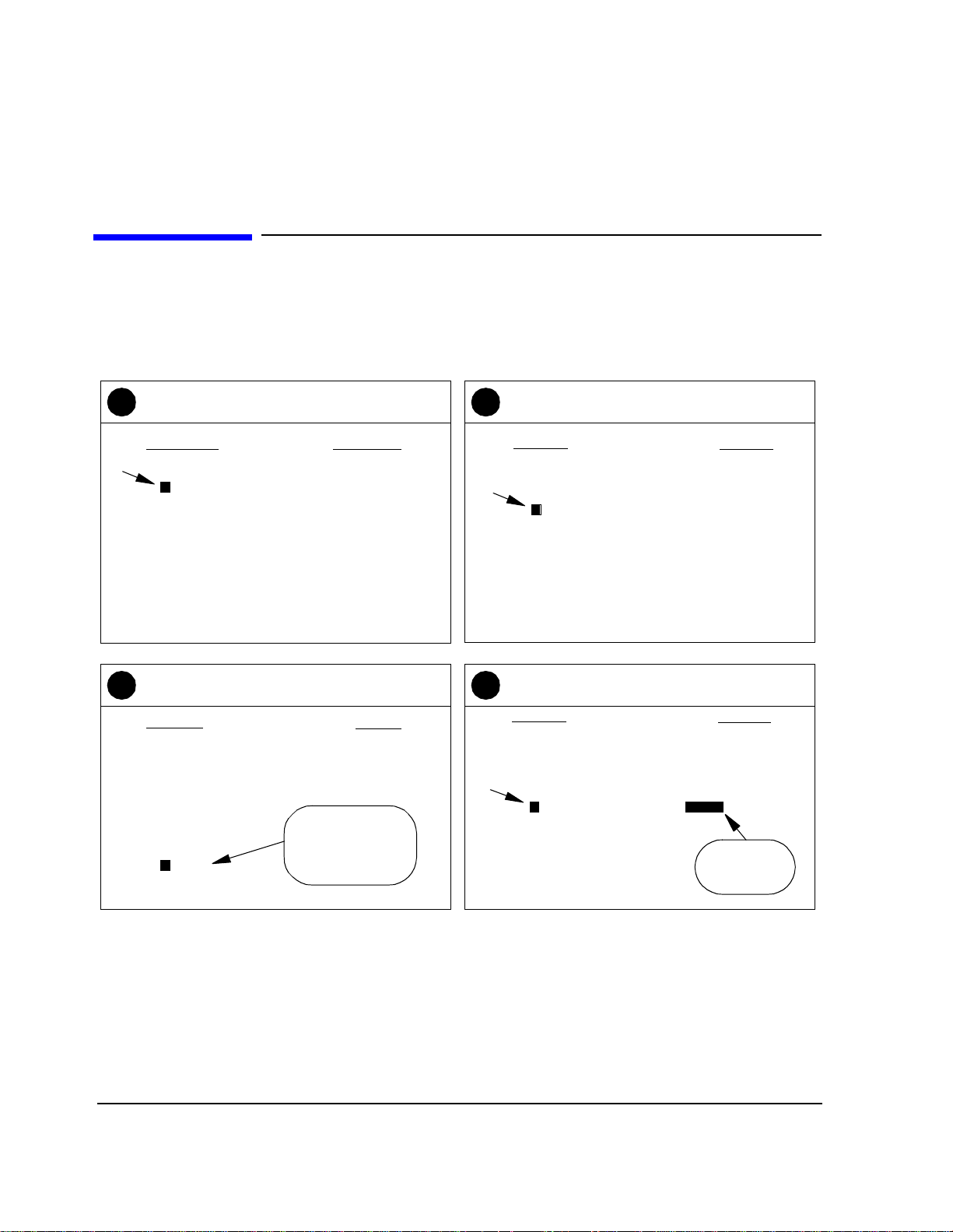
PCS Interfa ce and follow the steps of figure 3 and figure 4.
Chapter 1, Getting Started
Figure 3
Press
1
POWER.
15
Wait for display to
2
appear
(approximately 20
seconds).
Press PRESET.
3
Continued on the following page
Insert the
4
System U t il ity
Software card.
Page 16

Chapter 1, Getting Started
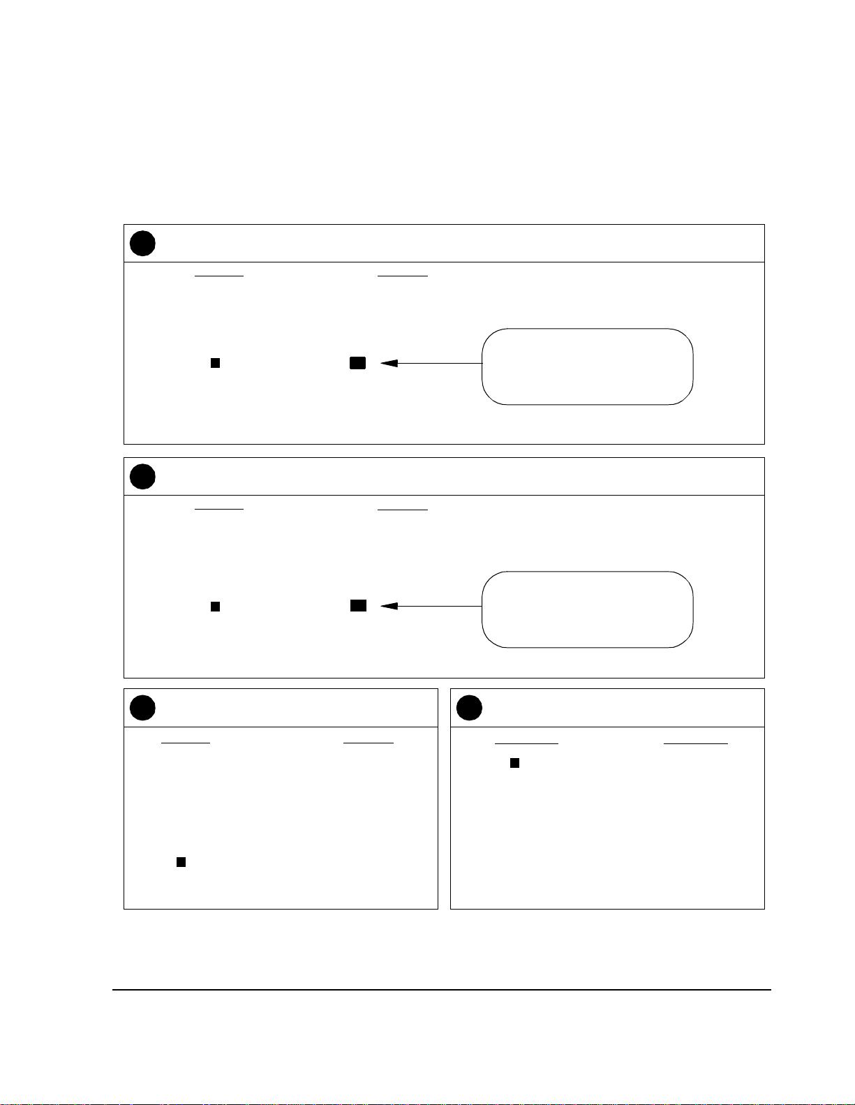
Step 2: Load and Run the CDMA/PCS BS Test Software
Press TESTS to display the
5
TESTS (Main Menu) screen.
Position the cursor at Card and select it.
7 8
Position the cursor at
6
Select Procedure Location: and select it.
Position the cursor at
Select Procedure Filename: and select it.
Position the cursor at Choices:
and select PCSCDMA.
PCSCDMA
XXXXXXXX
YYYYYYYY
Position the cursor at Run Test and
109
select it. The Software is now loading.
Figure 4
16
Loading Time:
First time:
approximately
one minu te .
After first time:
approx imately
15 seconds.
Page 17

Chapter 1, Getting Started
Step 2: Load and Run the CDMA/PCS BS Test Software
Navigation of the CDMA/PCS BS Test Software
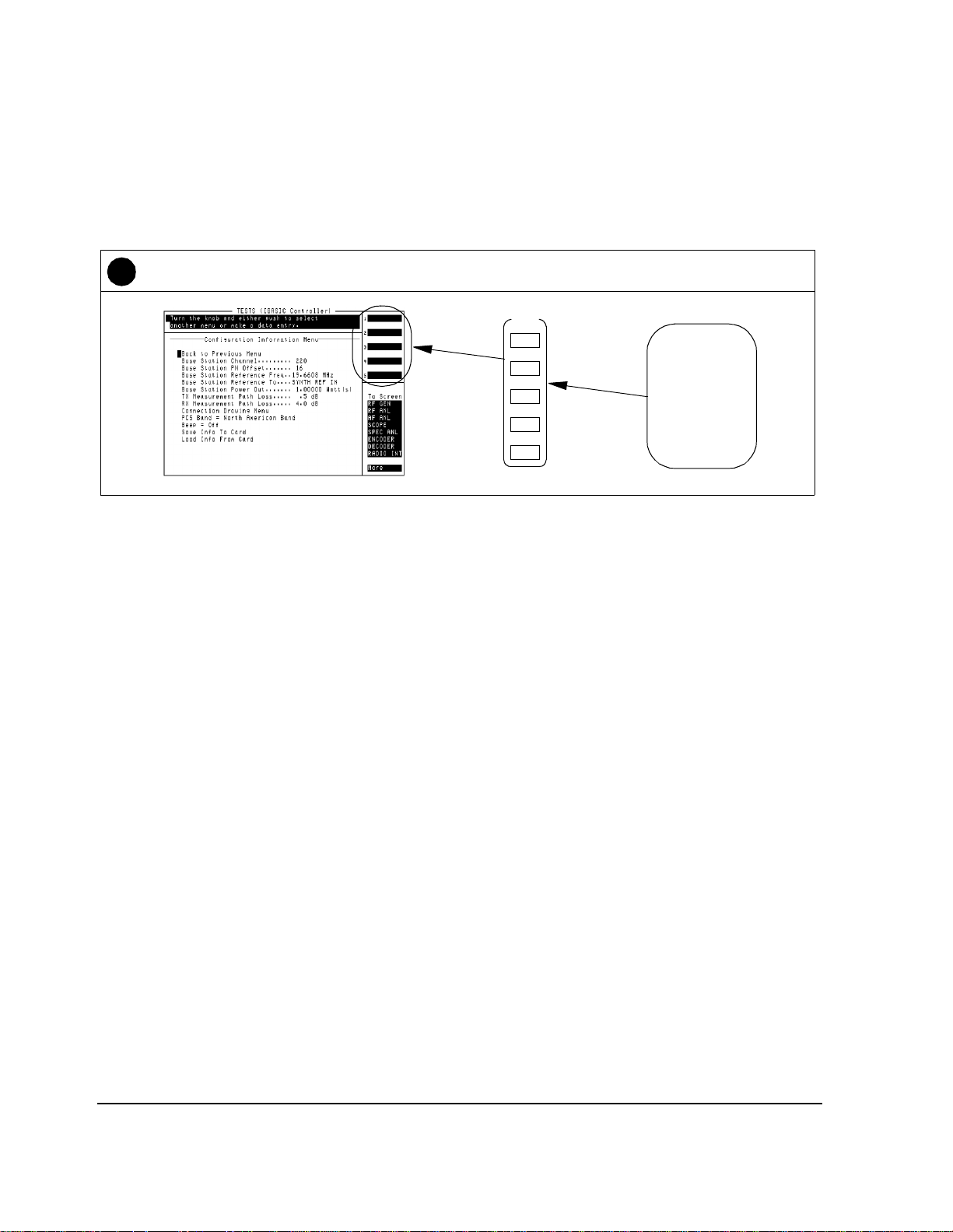
After the Software has loaded , you should see the CDMA/PCS BS Test
Software’s ma in menu screen on the d isplay of the Test Set (see figure 5).
Important features of this screen are indicated in the figure with note s on thei r
use.
Main Selection and Cursor Control
Some menu selections open lower-level
menus, others allow entry of numeric
data. To select a menu item, rotate the
knob until the curso r is front of the
selection and press the knob.
Entry Fields
Some main menu sel ections are entry fields. When these
are selected, a highlighted are a appears and you may key
in a value with the DATA keys, or rotate the knob to
change the value in the field. When the desired value is
set, press the knob or the ENTER key .
Quit
Tuned Frequency
This area displays the frequency
settings for the CDMA analyzer
and s i gn al gen er ator.
Figure 5 CDMA/PCS Test Software main menu features
17
USER Keys and their Fields
The USER Keys (k1 - k5) correspond
to fields 1-5 at the top right corner of
the test screen . They are used for
navigation through menus and for
making selections. In most lower-level
menus, a “Prev Menu” key is provided
to take you up one menu level.
Knob
The knob controls the
cursor position on the
display and is
sometimes used to
make num eric entr ies.
Page 18
Chapter 1, Getting Started
Step 3: Configure the Software
Step 3: Configure the Software
The first time you run the Software you must enter information about your setup
and the base station being tested. Use these steps:
From the CDMA PCS Main Menu, scroll to and
1
select Configuration Information Menu.
CDMA PCS Main Menu
Quit
Config ur a ti o n In f or ma tion Menu
Base Station Channel . . . . . . . . . 220
Base Station PN Offset . . . . . . . . 16
Search for PN Offset
Go to Spectrum Analyzer @ Present Chan
Go to Spectrum Analyzer & Enter Freq
Go to Code Domain Analyzer Screen
Perform Average Power Measurements
Measure Rho Parameters
Set up CDM A Generato r
Check Even Second Clock
Scroll to and select the clock frequency of the
3 4
timebase signal at the SYNTH REF IN port.
Select New Reference Frequency
1
1 . 2288
2
2 . 4576
4 . 9142
5
9 . 8304
10
15
19.6608
Typical reference
frequencies are
19.6608 MHz and
10 MHz.
Scroll to and select Base Station Reference
2
Freq.
Configuration Information Menu
Return to Main Menu
Base Station Channel . . . . . . . . . 220
Base Station PN Offset . . . . . . . . 16
Base Station Reference Freq. . . 19.6608 M Hz
Base Station Reference To . . . . SYNTH REF IN
Base Station Power Out . . . . . . . 1.00000 Watt(s)
TX Measurement Path Loss . . . . . .5 dB
RX Measurement Path Loss . . . . 4.0 dB
Connection Drawing Menu
PCS Band = North American Band
Beep = O f f
Save Info To Me mory
Load Info From Memory
Purge Inf o From Memory
Scroll to and select Base Station Power Out
and enter the level of your transmitted signal.
Configuration Information Menu
Return to Main Menu
Base Station Channel . . . . . . . . . 220
Base Station PN Offset . . . . . . . . 16
Base Stat ion Referen c e Freq. . . 19.6608 MHz
Base Station Reference To . . . . SYNTH REF IN
Base Station Power Out . . . . . . . 1.00000 Watt(s)
TX Measurement Path Loss . . . . . .5 dB
RX Measurement Path Loss . . . . 4.0 dB
Connection Draw ing Menu
PCS Band = North American Band
Beep = Off
Save Info To M e mory
Load Info From Memory
May be
approximate.
Continued on the following page
18
Page 19
Chapter 1, Getting Started
Step 3: Configure the Software
Scroll to and se lect TX Measurement Path Loss. Enter the loss (throu gh cables, couplers, and attenuators)
5
between your base station’s transmitter test port and the RF IN/OUT port of the PCS Interface.
Configuration Information Menu
Return to Main Menu
Base Station Channel . . . . . . . . . 220
Base Station PN Offset . . . . . . . . 16
Base Station Reference Freq. . . 19.6608 MHz
Base Station Reference To . . . . SYNTH REF IN
Base Station Power Out . . . . . . . 1.00000 Watt(s)
TX Measurement Path Loss . . . . 0.5 dB
RX Measurement Path Loss . . . . 4.0 dB
Connection Drawing Menu
PCS Band = Nor th A mer ic a n Ban d
Beep = Off
Save Info To Memory
Load Info Fro m Me mory
Scroll to and select RX Measurement Path Loss. Enter the loss of the RF cable (include loss through split-
6
ters, and so f orth) between you r base st ation’s recei ver test port and the RF IN /OUT port of the PCS Interface .
Enter the value into the highli ghted
field. The Software will compensate for cable loss, improving
measurement accuracy.
Configuration Information Menu
Return to Main Menu
Base Station Channel . . . . . . . . . 220
Base Station PN Offset . . . . . . . . 16
Base Station Reference Freq. . . 19.6608 MHz
Base Station Reference To . . . . SYNTH REF IN
Base Station Power Out . . . . . . . 1.00000 Watt(s)
TX Measurement Path Loss . . . . 0.5 dB
RX Measurement Path Loss . . . . 4.0 dB
Connection Drawing Menu
PCS Band = Nor th A mer ic a n Ban d
Beep = Off
Save Info To Memory
Load Info Fro m Me mory
Scroll to and select PCS Band.
7 8
Configuration Information Menu
Return to Main Menu
Base Station Channel . . . . . . . . . 220
Base Station PN Offset . . . . . . . . 16
Base Station Reference Freq. . . 19.6608 MHz
Base Station Referenc e To . . . . SYNTH REF IN
Base Station Power Out . . . . . . . 1.00000 Watt(s)
TX Measurement Path Loss . . . . 0.5 dB
RX Measurement Path Loss . . . . 4.0 dB
Connection Drawing Menu
PCS Band = Nor th A mer i c an Ba nd
Beep = Off
Save Info To Memory
Load Info From Memory
Enter the value into the highli ghted
field. The Software will compensate for cable loss, improving
measurement accuracy.
Scroll to and select your band of interest.
See "Selecting a PCS Band" on page 51.
PCS Band Selection Menu
North American Band
Korean Band Proposal 0
Korean Band Proposal 1
19
Page 20
Chapter 1, Getting Started
Step 3: Configure the Software
This completes t he required entr ies. You may now save you r entries or press the Main Menu (k5) ke y to retu rn
9
to the main menu. To save entr ies see, “Saving Config uration Information to Memory” in Chapter 3.
USER
k1
k2
k3
k4
k5
User keys 1-5
correspond
to the fields
on the top
right corner of
the test set
screen.
20
Page 21

Step 4: Perform CDMA Tests
Now that you have successfully run the Softwa re and entered your configuration
values, you can go on to making CDMA measurements. Refer to chapter 2,
"Making Measurements" to see detailed steps for performing CDMA
measurements.
Chapter 1, Getting Started
Step 4: Perform CDMA Tests
If You Had Problems
If you were unable to load and run the Software or make the required entries, refer
to chapter 4, "Troubleshooting" for help.
21
Page 22

Chapter 1, Getting Started
Step 4: Perform CDMA Tests
22
Page 23

2
Making Measurements
Making Measurements
This chapter contains descriptions of the most common receiver and transmitter
tests perfor med o n CDMA b ase station equipment. For each test, requirements
are listed and the steps to perform the measurement are provided.
23
Page 24

Chapter 2, Making Measurements
24
Page 25

Chapte r 2, M ak ing Measurements
Overview
Overv iew
This chapter present s measure ment t asks most commonl y perform ed when te sti ng
CDMA/PCS base station equipment. The measurements are separated by type:
transmitter tests, followed by the receiver tests. For descriptions of general
Software use, refer to chapter 3, "Operating Overview".
NOTE: The test procedures outlined in this chapter require that you have already configured the
Test System as outlined in chapter 1, "Getting Started".
Transmitter Measurements
Receiver Measurements
• "Ave r age P o w er " on pa g e 2 6
• "Modulation Qua lity (Rho)" on page 28
• "Code Domain Power" on page 30
• "Code Domain Timing" on pag e 32
• "Code Domain Phase" on page 34
• "Transmit Spectru m" on page 36
• "Receiver Se nsitivity" on page 40
• "Re ce iv er P er fo r m a n ce in Addit iv e N o ise" on pa g e 42
Other • "Search for PN Offset" on page 44
• "Check Even-Second Clock" on page 46
25
Page 26

Chapter 2, Making Measurements
Average Power
Average Power
Overview Average power is a time-averaged broadband measurement of the transmitte d
signal strength at the RF IN/OUT port on the front panel of the PCS Interface.
The average power measurement is “uncorrelated”; it does not require the
reference signals ( Even -Second clock and 19.6608 MHz timebase) needed for
other tests.
Transmitter Port
RF IN/OUT
Figure 6
CAUTION: Before performing any transmitter measurements, make sure that the power level applied
to the RF IN/OUT port of the PCS Interface does not exceed the published limit. For
CDMA base station signals this is 1 Watt (+30 dBm). You may have to use an external
attenuator or directional coupler, depending on the power output for your transmitter.
Signal levels greater than the specified maximum can cause damage to the test equipment .
NOTE: The test procedures outlined in this se ction require that you have already configured the
Test System as outlined in chapter 1, "Getting Started".
Requirements • You should know the following about your base station and setup:
❒ The base station channel number setting.
• You must ha ve a m eans o f c ont rolling t he base st ation to t urn on the t ran smitte r, s et the
channel number, and so fort h.
26
Page 27
Steps 1 Connect the equipment as shown in figure 6.
2 In the main menu, enter the Base Station Channel number for the transmitter
being tested.
3 Set up the base station to transmit on the channel number entered in step 2.
4 From the main menu, choose Perform Average Power Measurements.
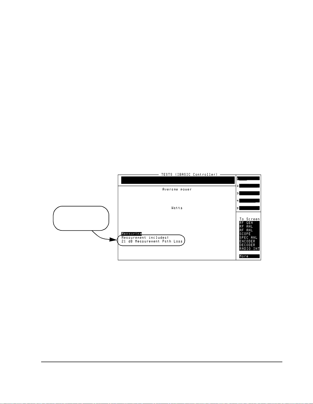
5 The resulting screen (see figure 7) will display average power (in Watts). The average
power displayed is correcte d for the loss value entered in the Configuration
Information Menu under TX Measurement Path Loss.
6 You can change the measurement’s uni ts to milliwatts or dBm using USER keys k3 and
k4, respectively.
7 USER key k1 will re-zero the power meter. It is not necessary to remove power from
the RF IN/OUT port of the PCS Interf ace to zero the power meter.
8 If you want to measure average power at another frequency, return to step 2.
9 Press the Main Menu (k5) key to return to the main menu.
Chapte r 2, M ak ing Measurements
Avera g e Po wer
Zero Pow
Watts
mW
1.28
In this ex am p le, loss
throug h a 2 0 dB at t en ua tor
was added to an additional
1 dB of cable loss.
dBm
Main Menu
Figure 7
Notes To minimize measurement errors due to temperature drift, occasional zeroing of
the power meter is recommended. An initial zeroing is perfor med when you enter
the
Average Power measurement screen. It is not necessary to remove the
signal from the RF IN/OUT port of the PCS Interface for zeroing.
27
Page 28

Chapter 2, Making Measurements
Modulation Quality (Rho)
Modulation Quality (Rho)
Overview In this measurement, the modulated signal is compared to an ideal, refe ren ce
waveform to determine the pe rformance of the transmit ter’s modu lation cir cuitr y.
Rho values are in the range of 0 to 1. A value of 1 indicates perfect correlation to
the reference (high modula tion qua lity). CDMA base station standards require
that transmitters have rho performance of 0.912 or higher.
EVEN SECOND/
SYNC IN
H
Transmitter Port
Even-Second
Clock
Time Base
H
RF IN/OUT
(Rear Panel)
SYNTH
REF IN
Figure 8
CAUTION: Before performing any transmitter measurements, make sure that the power level applied
to the RF IN/OUT port of the PCS Interface does not exceed the published limit. For
CDMA base station signals this is 1 Watt (+30 dBm). You may have to use an external
attenuator or directional coupler, depending on the power output for your transmitter.
Signal levels greater than the specified maximum can cause damage to the test equipment .
NOTE: The test procedures outlined in this se ction require that you have already configured the
Test System as outlined in chapter 1, "Getting Started".
Requirements • Synchronizat ion is required, so you must hav e an Even-Second Clock signa l and a
reference timebase (typically 19.6608 MHz) from the base station.
• You mu s t h ave the ability to tr ansmi t th e pilot ch a nnel onl y (W a lsh 0).
• You must know the following about the base statio n and s etup:
❒ The base station channel number setting.
❒ The PN Offset for the base-stat ion-under-test. I f you do not know the PN Offset,
determine it by selecting Search for PN Offset in the main menu.
28
Page 29

Steps 1 Connect the equipment as shown in figure 8.
2 In the main menu, enter the Base Station Channel number for the transmitter
being tested.
3 Also in the main menu, enter the Base Station PN Offset.
4 Set up the base station to transmit (pilot only) on the channel number entered in step 2.
5 Verify that the REF UNLOCK light on the front of th e Cellular Adapter is not lit.
6 Scroll to and select Measure Rho Parameters screen (see figure 9).
7 Read the value under the Rho field.
8 Read the values after the Time offset, Freq error, and Carrier ft fields.
9 Press the Main Menu (k5) key to return to the main menu.
Chapte r 2, M ak ing Measurements
Modulation Quality (Rho)
Figure 9
Notes If the message CANNOT CORRELATE appears on the screen , see "C DMA
Measurement not Correlat ing" in chapter 4, "Troubleshooting, on page 69."
For an on-screen summary of the possible causes and solutions, press the
Diagnose (k4) key.
29
Page 30

Chapter 2, Making Measurements
Code Domain Power
Code Domain Power
Overview The Code Domain Power measurement shows the relative power in eac h of the
Walsh channels of a transmitte d signal . Signal str ength of the Pilot, Paging, Sync,
and Traffic chan nels are displayed (in dB).
EVEN SECOND/
SYNC IN
H
Transmitter Port
Even-Second
Clock
Time Base
H
RF IN/OUT
(Rear Panel)
SYNTH
REF IN
Figure 10
CAUTION: Before performing any transmitter measurements, make sure that the power level applied
to the RF IN/OUT port of the PCS Interface does not exceed the published limit. For
CDMA base station signals this is 1 Watt (+30 dBm). You may have to use an external
attenuator or directional coupler, depending on the power output for your transmitter.
Signal levels greater than the specified maximum can cause damage to the test equipment .
NOTE: The test procedures outlined in this se ction require that you have already configured the
Test System as outlined in chapter 1, "Getting Started".
Requirements • You must have a means of tu rning on the base st ation t ransmit te r and ena bling va riou s
Walsh channels (Pilot, Sync, Traffic , and Paging).
• Synchronizat ion is required, so you must hav e an Even-Second clock signal a nd a
reference timebase (typically 19.6608 MHz) from the base station.
• You must know the following about the base statio n and s etup:
❒ The base station channel number setting.
❒ The PN Offset for the base-stat ion-under-test. I f you do not know the PN Offset,
determine it by selecting Search for PN Offset in the main menu.
30
Page 31

Steps 1 Connect the equipment as shown in figure 10.
2 In the main menu, enter the Base Station Channel number for the transmitter
being tested.
3 Also in the main menu, enter the Base Station PN Offset.
4 Scroll to and se lect Go to Code Domain Analyzer Screen.
5 Verify that the Measurement field at the bottom of the displ ay is set to Power. If it
is not, scroll down and set it to Power.
6 Turn on your base station transmitter.
7 If the signal is c orrela ted, you shoul d see a di spla y si milar to th at of figu re 11, s howin g
the pilot channel’s level (Walsh code 0) and any other Sync, Paging, or Traff ic channels
that are active.
8 To ret u r n to the main menu pre s s SH I F T , th en k1 , th e n E N T E R .
Chapte r 2, M ak ing Measurements
Code Domain Power
Figure 11 Code domain power display with a number of traffic channels enabled.
Notes The Tune Freq displayed at the bottom of the CODE DOMAIN ANALYZER screen
does not indicate the true tune d freq uency of the Test System. The tuned
frequency is calc ulated f rom you r entry for
viewed at the bottom of the main menu sc reen. Do not make changes to the Tune
Freq
setting of the CODE DOMAIN ANALYZER screen.
If you are planning to test C ode Domain Timing or Code Domain Phase, you can
use the
Measurement field to activate them without ha ving to return to the main
menu.
Refer to the HP 83203B or 83205A Cellular Adapter User’s Guide for more
details on the use of the Code Domain Power screen.
31
Base Station Channel and can be
Page 32

Chapter 2, Making Measurements
Code Domain Timing
Code Domain Timing
Overview Similar to the Code Domain Power test, this measur ement shows the timing
relationship bet ween the various Walsh channels and the Pilot channel.
EVEN SECOND/
SYNC IN
H
Transmitter Port
Even-Second
Clock
Time Base
H
RF IN/OUT
(Rear Panel)
SYNTH
REF IN
Figure 12
CAUTION: Before performing any transmitter measurements, make sure that the power level applied
to the RF IN/OUT port of the PCS Interface does not exceed the published limit. For
CDMA base station signals this is 1 Watt (+30 dBm). You may have to use an external
attenuator or directional coupler, depending on the power output for your transmitter.
Signal levels greater than the specified maximum can cause damage to the test equipment .
NOTE: The test procedures outlined in this se ction require that you have already configured the
Test System as outlined in chapter 1, "Getting Started".
Requirements • You must have a means of tu rning on the base st ation t ransmit te r and ena bling va riou s
Walsh channels (such as Pilot, Sync, Traffic , an d Paging).
• Synchronizat ion is required, so you must hav e an Even-Second clock signal a nd a
reference timebase (typically 19.6608 MHz) from the base station.
• You must know the following about the base statio n and s etup:
❒ The base station channel number setting.
❒ The PN Offset for the base-stat ion-under-test. I f you do not know the PN Offset,
determine it by selecting Search for PN Offset in the main menu.
32
Page 33

Steps 1 Connect the equipment as shown in figure 12.
2 In the main menu, enter the Base Station Channel number for the transmitter
being tested.
3 Also in the main menu, enter the Base Station PN Offset.
4 Scroll to and se lect Go to Code Domain Analyzer Screen.
5 Scroll to the Measurement field at the bottom of the display an d se t to Timing (if
not already selected).
6 Turn on your base stat ion transmit ter with the Pilot, Sync, Traffic, and Paging ch annels
enabled.
7 You should now see a display of relat ive timing, as shown in figure 13.
8 If you need to re-scale the vertical resolutio n, s elect Controls:Marker and then
scroll to the Time/div field and select from settings of 1 to 50 ns.
9 To return to the main m e nu pr ess SHI F T , th en k1 , th e n E N T E R .
Chapte r 2, M ak ing Measurements
Code Domain Timing
Figure 13
Notes The Tune Freq displa yed at the bottom of the CODE DOMAIN ANALYZER screen
does not indicate the true tune d freq uency of the Test System. The tuned
frequency is calc ulated f rom you r entry for Base Station Channel a nd can be
viewed at the bottom of the main menu sc reen. Do not make changes to the
Freq
setting of the CODE DOMAIN ANALYZER screen.
If you are planning to test Code Domain Power or Code Domain Phase, you can
use the
Measurement field to activate them without ha ving to return to the main
menu.
Refer to the HP 83203B or 83205A Cellular Adapter User’s Guide for more
details on the use of the
33
CODE DOMAIN ANALYZER screen.
Tune
Page 34

Chapter 2, Making Measurements
Code Domain Phase
Code Domain Phase
Overview Similar to the Code Domain Power measurement, thi s measurement shows the
relative phase relationship of the various Walsh channels referenced to the pilot
channel (Walsh 0).
EVEN SECOND/
SYNC IN
H
Transmitter Port
Even-second
Clock
Time Base
H
RF IN/OUT
(Rear Panel)
SYNTH
REF IN
Figure 14
CAUTION: Before performing any transmitter measurements, make sure that the power level applied
to the RF IN/OUT port of the PCS Interface does not exceed the published limit. For
CDMA base station signals this is 1 Watt (+30 dBm). You may have to use an external
attenuator or directional coupler, depending on the power output for your transmitter.
Signal levels greater than the specified maximum can cause damage to the test equipment .
NOTE: The test procedures outlined in this se ction require that you have already configured the
Test System as outlined in chapter 1, "Getting Started".
Requirements • You must have a means of turning on the base station transmitter and bringing up
various Walsh channels (such as Pilot, Sync, Tra ffic, and Paging).
• Synchronizat ion is required, so you must hav e an Even-Second clock signal a nd a
reference timebase (typically 19.6608 MHz) from the base station.
• You must know the following about the base statio n and s etup:
❒ The base station channel number setting.
❒ The PN Offset for the base-stat ion-under-test. I f you do not know the PN Offset,
determine it by selecting Search for PN Offset in the main menu.
34
Page 35

Steps 1 Connect the equipment as shown in figure 14.
2 In the main menu, enter the Base Station Channel number for the transmitter
being tested.
3 Also in the main menu, enter the Base Station PN Offset.
4 Scroll to and se lect Go to Code Domain Analyzer Screen.
5 Scroll to the Measurement field at the botto m of the displa y and set t o Phase (if not
already selected).
6 Turn on your base stat ion tran smitter wit h the Pilot, Sync, Traffi c, and Pagi ng channels
enabled.
7 You should now see a display of relat ive phase, as shown in figure 15.
8 If you need to re-scale the vertical resolutio n, s elect Controls:Marker and then
scroll to the Phase/div field and se le ct from sett ing s of 1 to 5 0 mR ad (mil li rad ia ns) .
9 To ret urn to the main menu pre s s S H I F T, then k1 , th en ENT ER.
Chapte r 2, M ak ing Measurements
Code Domain Phase
Figure 15
Notes The Tune Freq displa yed at the bottom of the CODE DOMAIN ANALYZER screen
does not indicate the true tune d freq uency of the Test System. The tuned
frequency is calc ulated f rom you r entry for Base Station Channel a nd can be
viewed at the bottom of the main menu sc reen. Do not make changes to the Tune
Freq
setting of the CODE DOMAIN ANALYZER screen.
If you are planning to t es t Code Domain Power or Code Domain Timing , you can
use the
menu.
Refer to the HP 83203B or 83205A Cellular Adapter User’s Guide for more
details on the use of the
35
Measurement field to activate them without ha ving to return to the main
CODE DOMAIN ANALYZER screen.
Page 36

Chapter 2, Making Measurements
Transmit Spectrum
Transmit Spectrum
Overview It is often useful to l ook at the transmitt er sig nal with the spe ctru m analyzer to se e
its overall symmetry and occupi ed bandwidth, and to ident ify poten tial sources of
interference . This se ct ion details two methods for accessing the spec trum
analyzer:
• Go to the spectrum anal yzer with the current channel as the center frequency, see
"Steps: Go to Spectrum Analyzer @ Present Chan" on page 37
• Go to the spectrum analyzer after entering a new center frequency, see "Steps: Go to
Spectrum Analyzer & Enter Freq" on page 38
H
Transmitter Port
H
RF IN/OUT
Figure 16
CAUTION: Before performing any transmitter measurements, make sure that the power level applied
to the RF IN/OUT port of the PCS Interface does not exceed the published limit. For
CDMA base station signals this is 1 Watt (+30 dBm). You may have to use an external
attenuator or directional coupler, depending on the power output for your transmitter.
Signal levels greater than the specified maximum can cause damage to the test equipment .
NOTE: The test procedures outlined in this se ction require that you have already configured the
Test System as outlined in chapter 1, "Getting Started".
Requirements • You must have a means of turning on the base station transmitter with modulation (if
looking at the trans mitted signal ) .
• You must know the following about the base statio n and s etup:
❒ The base station channel number setting (if looking at the transm itted signal).
36
Page 37
Chapte r 2, M ak ing Measurements
Transmit Spectrum
Steps: Go to Spectrum Analyzer @ Present Chan
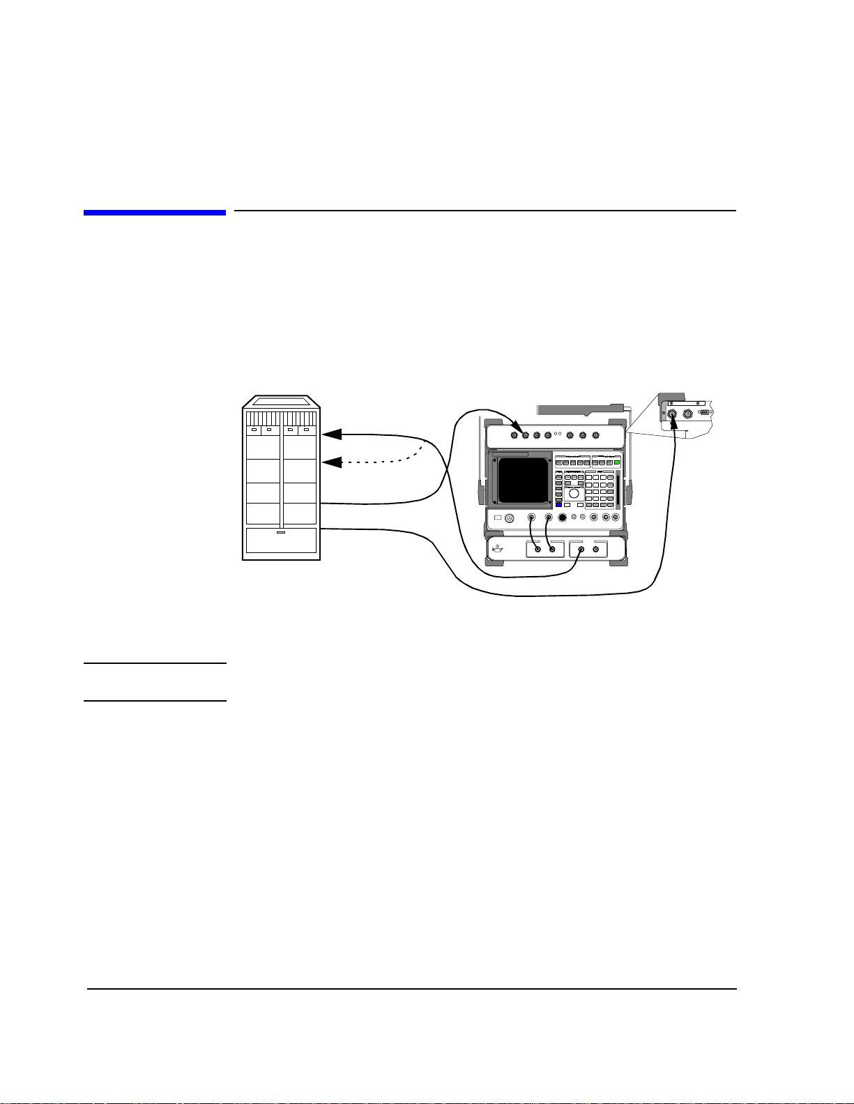
1 Connect the equipment as shown in fig ure 16.
2 In the main menu, enter the Base Station Channel number for the transmitter
being tested.
3 Turn on your base station transmitter.
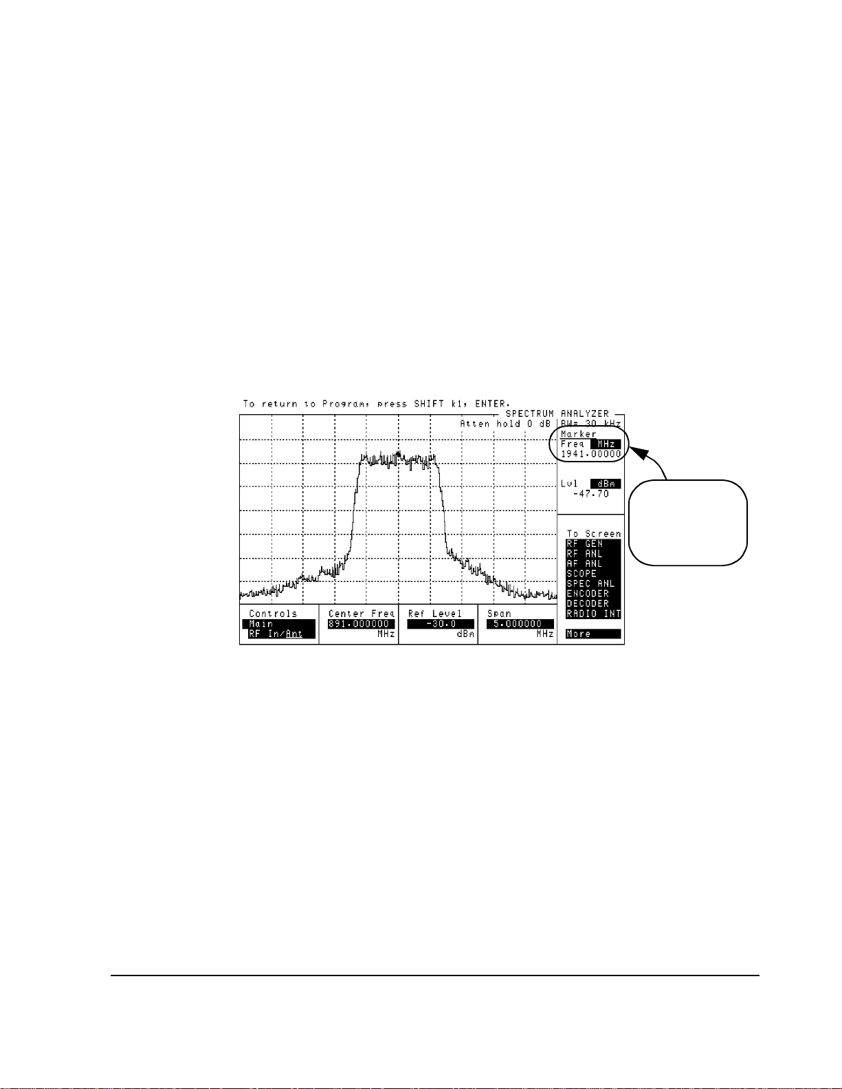
4 Scroll to and se lect Go to Spectrum Analyzer @ Present Chan. The
spectrum analyzer displ ay will appear and the center frequency wil l be set to match the
channel number entered in step 2 (see figure 17).
5 Use th e Controls area (set to Main) in the lower part of the sp ectrum analyz er
screen to make changes to the reference level and span settings as desired. Set the
Controls field to Marker to use marker functions.
6 To return to the main m e nu pr ess SHI F T , th en k1 , th e n E N T E R .
Note that the Marker
Frequency readout is
corrected to read the
actual PCS frequency.
Figure 17
37
Page 38
Chapter 2, Making Measurements
Transmit Spectrum
Steps: Go to Spectrum Analyzer & Enter Freq
NOTE: Your change to the attenuation value, if you make one, will only be effective while using
1 Connect the equipment as shown in figure 16.
2 Turn on your base station transmitter.
3 In the main menu, scroll to and select Go to Spectrum Analyzer & Enter
Freq.
4 The PCS Interface analyzer attenuati on se tting will ap pear in the field labelled
HP83236 Input Attenuator. This value is optimized based on your entries for
base station p ower and cable los ses. Howe ver, you can make chang es to t he value using
the HP83236 Input Attenuator field be fore going to the spec trum analyz er and
viewing the signal. For example, you may want to reduce the attenuation to improve
the signal strength relative to that of the spe ctrum analyzer nois e floor. Make the
change now if you want a different attenuation value (range is 0 to 40 dB).
the spectrum analyzer screen. When you return to the main menu, the value will be re-set
to the computed op t imum va lu e .
5 Scroll to and select Spectrum Analyzer Freq.
6 Enter the frequency of interes t using th e DATA keys (the rang e is 1710 to 1990 MHz)
and press ENTER .
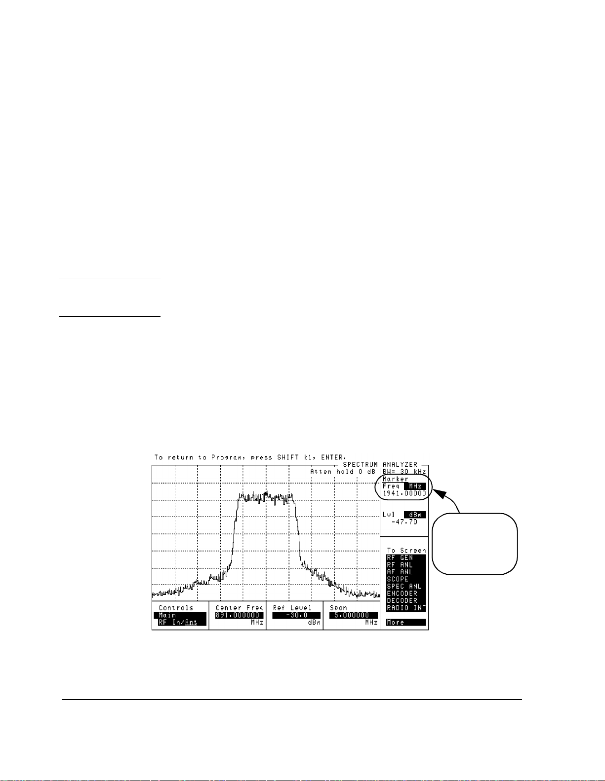
7 Scroll to and select Go to Spectrum Analyzer Screen to see the spectrum
analyzer display (see figure 18). The center fr eque ncy of the displayed signal matches
the frequency you entered in step 6.
8 Use the Controls area (set to Main) in the lower part of the spectrum analyzer
screen to make changes to the reference level and span settings as desired. Set the
Controls field to Marker to use marker functions.
9 To return to the main m e nu pr ess SHI F T , th en k1 , th e n E N T E R .
Figure 18
38
Note that the Marker
Frequency readout is
corrected t o r ead the
actual PCS frequency.
Page 39

Chapte r 2, M ak ing Measurements
Transmit Spectrum
Notes For either spectrum analyzer mode (Go To Spectrum Analyzer @ Present
Chan
or Go To Spectrum Analyzer & Enter Freq), do not make changes
to RF port selections, tune freque ncy, or other “setup” fields. You may change
spectrum-analyz er-specific settings suc h as Ref level, Span, and Marker.
39
Page 40

Chapter 2, Making Measurements
Receiver Sensitivity
Receiver Sensit ivity
Overview In this test, the CDMA generator sends a calibrated signal to the base station’s
receiver. For a given RF level, the resulting Frame Error Rate (FER) is measured.
Standards specify an FER of 1.0% or less at an RF level of
−119 dBm.
Receiver Port 1
Receiver Port 2
Even-second
Clock
Time Base
EVEN SECOND/
SYNC IN
H
H
RF IN/OUT
(Rear Panel)
SYNTH
REF IN
Figure 19
NOTE: The test procedures outlined in this se ction require that you have already configured the
Test System as outlined in chapter 1, "Getting Started".
Requirements • You will need a means of reading the Frame Error Rate (FER) from the base station.
The CDMA generator sends a random bit pattern which the base station decodes and
uses to calculate FER. Some means of reading the calcul ated value is required. Often
this is done via a laptop PC connected to the station equipment by serial or LAN port.
• This test requires synchroni zati on bet ween the Test System’s CDMA signal generato r
and the base-station-under-test. This is achieved using the Even-Second clock signa l
from the base st a tion.
• The CDMA generator shoul d be connect ed directl y to t he receive r’s inpu t(s). This can
be achieved by conne cting to only one input at a time or by using a spl itter to connect
to both inputs at once (if there is more than one receiver test port).
• You must know the following about your base station an d setup:
❒ The base station channel number setting.
❒ The Receiver PN Offset for the base-station-under-test (typically 0).
40
Page 41

Steps 1 Connect the equipment as shown in figure 19.
2 In the main menu, enter the Base Station Channel number.
3 Scroll to and se lect Setup CDMA Generator.
4 Scroll to RF Level and enter the signal generator level for your sensitivity
measurement (in dBm).
5 Scroll to and set the Generator Mode to Data.
6 Scroll to and set the RX PN Offset, typically to 0.
7 Scroll to and se t the Data Source to Random.
8 At this time, the CDMA generator is sending random data at the lev el you entered in
step 4.
9 You can now read the calculated FER from the PC or other means.
10 If desired, use the RF Level selection to change the signal strength and read the
resu lting F ER.
11 To ret u r n to th e main me nu, press the Main Menu (k5) key.
Chapte r 2, M ak ing Measurements
Receiver Sensitivity
Figure 20
Notes The cable loss (includin g losses through splitters, couplers, and so forth) entered
into the Configuration Information Menu screen is taken into account
when signal generator RF level set tings are made. The level at the PCS Interface
RF IN/OUT port is increased by the lo ss am ount so the displayed RF level
indicates the true leve l del ivered to the base station’s receive r test port(s).
The field
testing, if required. Normally, mobiles transmit on system time which
corresponds to an offset of 0 (the default va lue in the Software menu).
41
RX PN Offset is provided for you to change the offset for your
Page 42
Chapter 2, Making Measurements
Receiver Performance in Additive Noise
Receiver Performance in Additive Noise
Overview In this test, the CDMA signal generator is used with the Additive White Gaus sian
Noise (AWGN) source to si mulate an uplin k signa l to the base stat ions’s r eceiver .
Various levels of signal -to-noise (E
Error Rate (FER) is measured at each Eb/No level.
) can be used and the resulting Frame
b/No
Receiver Port 1
Receiver Port 2
Even-second
Clock
Time Base
EVEN SECOND/
SYNC IN
H
H
RF IN/OUT
(Rear Panel)
SYNTH
REF IN
Figure 21
NOTE: The test procedures outlined in this se ction require that you have already configured the
Test System as outlined in chapter 1, "Getting Started".
Requirements • You will need a means of reading the Frame Error Rate (FER) from the base station.
The CDMA generator sends a random bit pattern which the base station decodes and
uses to calculate FER. Some means of reading the calcul ated value is required. Often
this is done via a laptop PC connected to the station equipment by serial or LAN port.
• This test requires synchroni zati on bet ween the Test System’s CDMA signal generato r
and the base-station-under-test. This is achieved using the Even-Second clock signa l
from the base st a tion.
• The CDMA generator shoul d be connect ed directl y to t he receive r’s inpu t(s). This can
be achieved by conne cting to only one input at a time or by using a spl itter to connect
to both inputs at once (if there is more than one receiver test port).
• You must know the following about your base station an d setup:
❒ The base station channel number setting.
❒ The Receiver PN Offset for the base-station-under-test (typically 0).
42
Page 43

Chapte r 2, M ak ing Measurements
Receiver Performance in Additive Noise
Steps 1 Make the equipment connections as shown in figure 21.
2 On th e ma in menu scre en , en t er th e Base Station Channel number.
3 Scroll to and se lect Setup CDMA Generator.
4 Set the Generator Mode to Eb/No. Note that a new field appears called
Eb/No Level.
5 Set the Eb/No Level as called for in the test standard or in your base station test
procedures (for example, 5.5 dB).
6 Scroll to and set the RX PN Offset, typically to 0.
7 Scroll to and se t the Data Source to Random.
8 Set the RF Level as called for in your test procedure.
9 At this point, the CDMA si gnal generator is transmitti ng with random data and noise.
Read the resulting Frame Error Rate from the base station.
10 If desired, change th e Eb/No Level according your test procedure and read the
resulting FER value.
11 When finished, return to the ma in menu by pressing the Main Menu (k5) USER key.
Figure 22
Notes The cable loss (includin g losses through splitters, couplers, and so forth) entered
into the Configuration Information Menu screen is taken into account
when signal generator RF level set tings are made. The level at the PCS Interface
RF IN/OUT port is increased by the lo ss am ount so the displayed RF level
indicates the true leve l del ivered to the base station’s receive r test port(s).
The field
testing, if required. Normally, mobiles transmit on system time which
corresponds to an offset of 0 (the default va lue in the Software menu).
43
RX PN Offset is provided for you to change the offset for your
Page 44

Chapter 2, Making Measurements
Search for PN Offset
Search for PN Offset
Overview If you are unsure of the PN offset for the tr ansmitter and channel you plan to test,
the Software provides this utility to search for and display the PN offset.
EVEN SECOND/
SYNC IN
H
Transmitter Port
Even-second
Clock
Time Base
H
RF IN/OUT
(Rear Panel)
SYNTH
REF IN
Figure 23
CAUTION: Before performing any transmitter measurements, make sure that the power level applied
to the RF IN/OUT port of the PCS Interface does not exceed the published limit. For
CDMA base station signals this is 1 Watt (+30 dBm). You may have to use an external
attenuator or directional coupler, depending on the power output for your transmitter.
Signal levels greater than the specified maximum can cause damage to the test equipment .
NOTE: The test procedures outlined in this se ction require that you have already configured the
Test System as outlined in chapter 1, "Getting Started".
Requirements • You must have a means of turning on the base station transmitter with modulation.
• You must know the following about the base statio n and s etup:
❒ The base station channel number setting.
44
Page 45

Chapte r 2, M ak ing Measurements
Search fo r PN Offset
Steps 1 Connect the equipment as shown in figure 23.
2 In the main menu, enter the Base Station Channel number for the transmitter
being tested.
3 Turn on your base station transmitter (pilot channel must be on).
4 Scroll to and select Search for PN Offset and the Software will begin the
search. The Softw ar e will se arch for the PN offset in segments, displaying a message
on the screen to show which segment is being searched.
5 When the Software has found the PN Offset, you should see a dis play of the offset:
PN OFFSET = 24
NOTE: When the So ftwar e f in ds th e PN Of fset , it wil l ins er t t he va lue au toma tica lly in to the Base
Station PN Offset field on the main menu screen.
Notes During the search, the following error message will often appear:
Cannot correlate to input signal. Check setup.
This is norma l for the Search for PN Offset.
If the Software i s un abl e to find the PN Offset, it will display the message:
PN OFFSET NOT FOUND
If you decide to a bort (stop) the PN offset search, press the Main Menu (k5) key.
There can be a delay of several seconds before you see the main menu displa y.
See the secti on on PN Offs et in " CDMA Measurement not Cor relatin g" in chapter
4, "Troubleshooting, on page 69.".
45
Page 46

Chapter 2, Making Measurements
Check Even-Second Clock
Check Even-Seco nd Clo ck
Overview Most CDMA transmitter t es ts require an Even-Second clock signal from the base
station in order to correlate the measur e ment. If you are rece iving an error stating
Cannot correlate to input signal. Check setup. , you may have a
problem with your Even- Second clock signal. This Software utility allows you to
check for a valid clock signal from the base station.
EVEN SECOND/
SYNC IN
H
Even-Second
Clock
Time Base
H
(Rear Panel)
SYNTH
REF IN
Figure 24
NOTE: The test procedures outlined in this se ction require that you have already configured the
Test System as outlined in chapter 1, "Getting Started".
Requirements • This test requires that you temporari ly connect the Even-Second clock signal to the
TRIGGER / QUALIFIER IN port of the Cellular Adapter.
NOTE: Be sure to return the Even-Second clock signa l to the EVEN SECOND / SYNC IN port of
the Cellular Adapter when finished. The Software will prompt you to make this change.
46
Page 47

Chapte r 2, M ak ing Measurements
Check Even-Second Clock
Steps 1 You can start wi th th e con nec ti on s sho wn in figure 24. You will get prompts from the
Software to change the Even-Second clock connection when needed.
2 In the main menu, scroll to and select Check Even Second Clock.
3 You will have to make a change to the connections, as shown on the display. Switch
the Even-Second cloc k signal from the EVEN SECOND/SYNC IN port to the
TRIGGER/QUALIFIER IN port on the Cellular Adapter. Once you have made the
connection, press the Continue (k2) key.
4 The Software will beg in checking for a valid cl ock signal. This will take a few secon ds.
When it has found a valid signal, you will se e the message EVEN SECOND CLOCK
FOUND. If the Software finds no valid clock, you will see the message NO CLOCK
FOUND. In that c as e, see the documentation o n your base station to verify that you are
connecti ng to th e co r rec t p ort a nd t o s ee if any swi tch es m ust b e s et to enab le t he c loc k
signal.
5 To go on, press the Continue (k2) key.
6 Reconnect the Eve n-Second cl ock signal c onnection t o the EVEN SE COND/SYNC port
on the Cellular Adapter. After you have done this, press the Continue (k2) key to
return to the main menu.
Notes See the section on the clock timing signal in "CDMA Measurement not
Correlating" in chapter 4, "Troubleshooting, on page 69."
47
Page 48

Chapter 2, Making Measurements
Check Even-Second Clock
48
Page 49

3
Operating Overview
This chapter describes general operation of the Software.
49
Operating Overview
Page 50

Chapter 3, Operating Overview
Overview
Overview
This chapter provides detail on Softwa re operations not covered in chapter 1,
"Getting Started" or chapter 2, "Making Measurements".
Configuration Information
Reference Information
• "Selecting a PCS Band" on page 51
• "Compensating for TX and RX Measurement Path Loss" on page 53
• "Saving Configuration Information to Memory" on page 54
• "Loading Configura tion Information from Memory" on page 55
• "Purging Configuration Information from Memory" on pag e 56
• "Using Autostart" on page 57
• "Viewing Instrument Connections" on page 58
• "Setting the Test System “Beep”" on pag e 59
• "An Alternativ e Test -S ystem-to-Base-Station Timebas e Configuration" on page 60
50
Page 51

Chapter 3, Operating Overview
Selecting a PCS Band
Selecting a PCS Band
With the HP 83236B PCS Interface, the Software supports sever al “channel
plans” used i n PCS sy ste ms inter nationa lly. By se lecting the appropr iate plan, you
can use channe l number s (r ather than f requencie s) t o tu ne the si gna l gener ator a nd
analyzer for testi ng.
NOTE: If you use the HP 83236A P CS Interf ace, only th e North Am erica n Band i s support ed, a nd
the procedure described on this page does not ap ply.
The band choices in this revision of Software are:
• North American Band
• Korean Band Proposal 0
• Korean Band Proposal 1
Steps To select a new PCS Band:
1 From the main men u, sc roll to and s e lect Confi guration Information Menu.
2 Scroll to and se lect PCS Band.
3 Choose one of the band choi ces by scrol ling to it and pre ssing the knob. The choice will
then appear in the Configuration Information Menu.
4 To ret u r n to th e main me nu level, press th e Main Menu (k5) key.
Notes Once you’ve selected the appropr ia te channel plan, all you need to do to tune the
Test System is enter the channel number in the Base Station Channel field .
The Test System makes t he conversio n to a f requenc y and tunes the gene rator and
analyzer. If you would like to know the frequency settings for a given channel
number and PCS Band combination, refer to table 1 on page 52.
51
Page 52

Chapter 3, Operating Overview
Selecting a PCS Band
Table 1 Channel plans for PCS Band selections.
PCS Band Channel Plan To calculate the transmitter frequency:
North American Band Channel range: 0 to 1199
Transmitter frequencies:
1930 to 1989.95 MHz
Offset: −80 MHz
Channel spacing: 50 kHz
Korean Band Proposal 0 Channel range: 0 to 1300
Transmitter frequencies:
1805 to 1870 MHz
Offset: −90 MHz
Channel spacing: 50 kHz
Korean Band Proposal 1 Channel range: 1 to 1300
Transmitter frequencies:
1805 to 1870 MHz
Offset: −90 MHz
Channel spacing: 50 kHz
TX freq = (channel × 0.05) + 1930 MHz
RX freq = (channel × 0.05) +1850 MHz
TX freq = (channel × 0.05) + 1805 MHz
RX freq = (channel × 0.05) +1715 MHz
Channels 1 to 600:
TX freq = (channel × 0.05) + 1840 MHz
RX freq = (channel × 0.05) +1750 MHz
Channels 601 to 1300:
TX = ((channel − 600) × 0.05) + 1805 MHz
RX = ((channel − 600) × 0.05) +1715 MHz
52
Page 53

Chapter 3, Operating Overview
Compensating for TX and RX Measurement Path Loss
Compensating for TX and RX Measurement Path Loss
The Software can compensate for losse s (t hrough cables, attenuators, couplers,
and so forth) between the Te st Sys tem and t he ba se statio n f or the be st accuracy in
average power and receiver measurements. The loss values are entered into the
Configuration Information Menu and are saved to memory if the Save
Info To Memory
Requirements You must know the following loss values:
• The total loss (in dB) between the base station’s transmitter test port and the
RF IN/OUT port of the PCS Interface.
• The total loss (in dB) between the RF IN/OUT port of the PCS Interface and the base
station’s receiver test port.
feature is used.
These values should include losse s through any cables, splitters, a ttenuators, and
directional couple rs used in your test setup.
Steps 1 From the main menu, select Configuration Information Menu.
2 Scroll to and sele ct TX Measurement Path Loss and ente r the lo ss b etw een the
transmitter’s test por t and the RF IN/OUT port of the PCS Int erface. Once sele cted, you
can use the knob to scroll up a nd down in 1 dB increments or you may enter the value
directly using the DATA keys. Press ENTER or the knob when the correct value
appears in the inverse field.
3 Scroll to and select RX Measurement Path Loss and enter the total los s between
the PCS Interface’s RF IN/OUT port and the receiver’s test port.
4 To ret u r n to th e main me nu, press the Main Menu (k5) key.
Notes The loss valu es you ente red in the steps above will not be save d unl ess you use the
Save Info to Memory feature. See "Saving Configuration Information to
Memory" on page 54.
53
Page 54

Chapter 3, Operating Overview
Saving Configuration Information to Memory
Saving Configuration In f or m at ion to Memor y
The information about your set up and base station entered into the
Configuration Information Menu can be saved to memory. This saves
time when running the Software at a later date and hel ps to prevent entry errors.
The stored data is loaded automat ically any time you re-run the Software. If you
make changes to th e on-scre en values and you want to retur n to your def aults, you
can also load the stored data manually.
Requiremen ts • An initialize d RAM disk . (T he firs t time you run the Software it will set up and
initialize the RAM disk automat ically.)
NOTE: A “RAM disk” is a virtual memory loca tion that uses a small portion of internal
non-volatile RAM of the Test Set. No memory card is required to save and load
configurations.
Steps 1 From the main menu, choose the Configuration Information Menu.
2 Check to make sure that the f ollowing entries in the Configuration
Information Menu are set with your desired values:
❒ Base Station Channel
❒ Base Station PN Offset
❒ Base Station Reference Freq
❒ Base Station Reference To
❒ Base Station Power Out
❒ TX Measurement Path Loss
❒ RX Measurement Path Loss
❒ PCS Band
❒ Beep
3 Scroll down to Save Info To Memory and press the knob. Th e screen will be
updated and the stora ge will be complete.
4 To return to the main m e nu level, pr ess the Main Menu (k5) key.
Notes See "Loading Configuration Information from Memory" on page 55 for a
description of how your saved values can be reloaded.
See "Purging Configuration Infor mation from Memory" on page 56 for a
description of how to clear the saved values.
54
Page 55

Chapter 3, Operating Overview
Loading Configuration Information from Memory
Loading Conf igu r at ion Information from Memory
The information about your set up and base station entered into the
Configuration Information Menu can be saved in memory. This data is
loaded automatically whe n you re-run the Software. You can also load the data
manually. This procedure des cribes steps for manually loading the data .
Requiremen ts • Data previously saved to a RAM disk.
Steps 1 From the main menu, choose the Configuration Information Menu.
2 Scroll down to Load Info From Memory and press the kn ob. T he loa di ng proc ess
takes only a fraction of a second. You should see your saved values in the
Configuration Information Menu.
3 To ret u r n to th e main me nu level, press th e Main Menu (k5) key.
Notes See "Saving Configuration Information to Memory" on page 54 for a descriptio n
of saving the settings to memory.
55
Page 56

Chapter 3, Operating Overview
Purging Configuration Information from Memory
Purging Conf igu r at ion In f ormation from Mem or y
The information about your set up and base station entered into the
Configuration Information Menu can be saved in memory. This data is
loaded automatically whe n you re-run the Software. In some instances however,
you might wish to use default data. If so, you must clear your saved values from
memory. This procedure describe s steps for manually purging the memory.
Requiremen ts • Data previously saved to a RAM disk.
Steps 1 From the main menu, choose the Configuration Information Menu.
2 Scroll down to Purge Info From Memory and press the knob. Th e purging
process takes only a fraction of a sec ond. The next time the Software is run, the
Configuration Information Menu will be loade d with default values.
3 To ret urn to the main menu level, pre s s th e Main Menu (k5) key.
Notes The fact that configuration information has been purged from memory is shown
in the Configuration Information Menu whenever you purge the data
manually, using the steps outlined above.
See "Saving Configuration Information to Memory" on page 54 for a description
of saving the settings to memory.
56
Page 57

Using Autostart
Chapter 3, Operating Overview
Using Autostart
“Autostart” is a feature of the Test Set’s IBASIC controller and is used to
customize the instrumen t for a speci fic task. The autostart feature allows you to
“flip a switch” to configure the Test Set to aut omatically ru n whatever program is
currently s tored in its non-volatile memory when the instrument is fir st turned on.
Turning On the Autostart Feature
Turning Off the Autostart Feature
If you would like your Test System to “boot up” into the main menu of the
CDMA/PCS BS Test Software screen, follow these ste ps:
1 Scroll to and se lect Go to Spectrum Analyzer @ Present Chan. This is
done only to pause the Software in a known state.
2 Press the TESTS key.
3 Scroll to and select Execution Cond.
4 Scroll to the last field at the bottom of the screen and set Autostart Test
Procedure on Power-up to On
5 To return to the Software’s main menu press SHIFT, then k1, then ENTER.
With this setting, whenever you apply power to the Test Set it will automatically
run the Software pr ogram loaded in non-vola tile memory. This wi ll configure the
Test Set to act as a “CDMA tester” (assuming that the CDMA/PCS Software is
loaded) and saves steps in testing.
If you power up t he Test Set later and wa nt to use other manual functions, sim ply
Quit (k5) from the main menu and then select the other function.
select
Turning the autostart fea ture off is done using the steps above, except you would
set the Autostart Test Procedure on Power-up mode to Off.
.
Notes The autostart feature continues to work even if you load and r un another program
on the Test Set. The new pr ogram will be auto matically r un the next tim e you turn
on the Test Set.
57
Page 58

Chapter 3, Operating Overview
Viewing Instrument Connections
Viewing Instrument Connections
In setting up your Test System, you may have questions about connections
between the Test Set, Cellular Adapter, and PCS Interface as well as the
connections to the CDMA/PCS base stati on. I n the Configuration
Information Menu
front and rear panels.
Steps 1 From the main menu, select Configuration Information Menu.
2 Make sure that you have your desired entries in the fields of the Configuration
Information Menu (see Notes, below).
3 Scroll to and se lect Connection Drawing Menu.
4 For a diagram of front panel connections, scroll to and select Show Instrument
Front Panel Connections.
5 For rear panel conne ction s, s croll to and sele ct Show Instrument Rear Panel
Connections.
6 You can exit the connection diagram screen by pressing the Continue (k2) key.
7 Press the Prev Menu (k5) key to return to the Configuration Information
Menu.
8 Press the Main Menu (k5) key to return to the main menu level.
is a selection that displa ys connection diagrams for the
Notes The connection diagrams change as a function of the entries into the
Configuration Information Menu. For this reason, make sure you have
entered your desired value s bef ore viewing the instrument connections.
Connection diagrams for each CDMA test are also shown in chapter 2, "Making
Measurements".
58
Page 59

Chapter 3, Operating Overview
Setting the Test System “Beep”
Setting the Test System “Beep”
The Software can provide an audio tone (bee p) to let you know when selections
are made in the menu screens. This beep sounds when you change menu screens,
choose an entry field, and when you complete an entry.
In its default mode, the beep functio n is set to a medium volume (Quiet). You can
customize the beep function as foll ows:
• If you don’t want to hear the beep at all, you can turn it off.
• For noisy environments, you can set the beep to a high volume (Loud).
Steps 1 From the main menu, select Configuration Information Menu.
2 Scroll to an d select Beep.
3 Use the cursor to scroll and choose one of the three options (Off, Quiet, or Loud).
4 Press the Main Menu (k5) key to return to the main menu level.
Notes The beep level you set will not be saved unless you use the Save Info to
Memory
feature. See "Saving Configuration Information to Memory" on page 54 .
59
Page 60

Chapter 3, Operating Overview
An Alternative Test-System-to-Base-Station Timebase Configuration
An Alternative Test -Sy st em-to -Ba s e-Station Timebase Config ura tion
Chapter 1 describes the most common method of connecting timebases between
the Test System and the base- station -under-te st. This se ction shows a n alternati ve
way of connecting the timebases using the CDMA TIMEBASE IN port of the
CDMA Cellular Adapter (rather than the rear-panel SYNTH REF IN port).
Steps 1 Connect the timebases a s shown i n figure 25. Note the conne ction s from the BNC “tee”
on the Test Set’s 10 MHz REF OUTPUT to both the Cellular Adapter and the PCS
Interface.
NOTE: This figure does not illustrate all rear-panel connections between the Cell ular Adapter and
Test Se t . Refer to th e Cellular Ad apter User’s Guide to ver ify these connections.
2 From the main menu, select Configuration Information Menu.
3 Note the selection for the Base Station Reference To field. If it is s e t to
SYNTH REF IN, scroll down to the line and press the knob to change it to read
CDMA TB IN. Otherwise, you may skip this step.
4 Note the selecti on fo r Base Station Reference Freq . If it does not matc h th e
timebase frequency supplied by the base station (typically 19.6608 MHz or
10 MHz), scroll to the line , pre ss the knob, and select the appropriate value.
5 To return to the main m e nu , press the Main Menu (k5) key.
Notes The timebase settings you made in the steps above will not be saved unless you
use the Save Info to Memory feature. See "Saving Config urati on Informatio n
to Memory" on page 54.
60
Page 61

CDMA Base Station
Even-Second
Clock
Chapter 3, Operating Overview
An Alternative Test-System-to-Base-Station Timebase Configuration
CDMA
TIMEBASE IN
EVEN SECOND/
SYNC IN
83205A
H
RF IN/OUTTORF IN/OUT
H
POWER
CDMA CELLULAR ADAPTER
TRIGGER /
QUALIFIE R
MAX.PWR
IN
83236B
PCS INTERFACE
ONOFF
DATA
IN
CDMA
EVEN SEC -
TIMEBASE
OND/
SYNC IN
TEST SET
FROM D UPLEX OU T TO ANT IN
PWR REF
UNLOCK
DIAGNOSTIC
MONITOR
1.228 8 M H z
19.6608 MHz
OUT
OUT
16 X CHIP
1.8-2.0 GH z UUT
RF IN/OUT RF OUT only
19.6608 MHz Clock
(or other reference)
SYNTH REF IN
Figure 25
HP - IB
REF IN
CDMA CLOCK OUTPUTS
CONTROL I/OSYNTH REF IN10 MHz OUT
CW
RF INIQRF OUT
AUX
DSP IN
Q BASEB AND OUT
10 MHz
REF OUT
OPTIONAL
MOD OUT
SERIAL PORT
I BASEB AND OUT
114.3 MHz IF IN
10 MHz REF OU TPUT
(A BNC “tee” is required
to make these connections)
61
Page 62

Chapter 3, Operating Overview
An Alternative Test-System-to-Base-Station Timebase Configuration
62
Page 63

4
Troubleshooting
Use this chapte r if you ha ve e ncountered S oftware e rrors o r if you ar e questionin g
measurement results.
63
Troubleshooti ng
Page 64

Chapter 4, Troubleshooting
Overview
Overview
Use table 2 to locate your problem or a received error message, then refer to the
page number shown.
Problem or error message Refer to:
Memory overflow errors "Memory Overflow Errors" on page 65
Message: HP-IB Command not accepted. Option not
installed.
Message: Verify PCS Interface is connected and on. Retry?
Message: Compensation not performed. Check DUPLEX
OUT cable. Retry?
Configuration Information is not updated "Configuration Information is Not
The menu screens you see do not match those in this book "Menu Screens in this Book do not
Loading and running the software
Message: Cannot correlate to input signal. Check setup. "CDMA Measurement not Correlating"
Unable to read frame error rate (FER) or unexpectedly high
readings (receiver tests)
Measuremen ts
Average power "Average Power" on page 73
Modulation quality (rho) "Rho Measurements" on page 74
Code domain power, timing, or phase "Code Domain Measurements " on page
"Test System Configuration Errors at
Runtime" on page 66
"Other Test System Configuration
Errors" on page 67
Updated as Saved" on page 67
Match the Sc reens th at You See" on p age
68
on page 69
"Frame Error Rate (Receiver
Measurements)" on page 71
74
Receiver tests "Receiver Test s" on page 74
Questionable Measurement Results
Table 2
64
Page 65

Errors When Loading and Running the Software
Errors When Loading and Running the Software
Chapte r 4, T roublesho ot ing
Memory Overflow Errors
Problem:
The random access memory (RAM) space of the Test Set is shared by IBASIC
programs and the Save/Recall storage r egisters. If yo u have saved a large num ber
of registers in your Te st Set , you may e ncounter a “memory overf low” e rror when
you first attempt to load the Software.
Solution:
You will need to cle ar up some RAM space by dele ting some or all of your saved
registers. You can do this selectively (one register at a time) or you can clear all
storage registers a t once (gl obally).
NOTE: Clearing the registers, whether selectively or globally, is permanent. You cannot retrieve
the registers once de leted. You have an option to save registers to a RAM memory card, as
well. Consult the HP 8921 User’s Guide for instructions on this procedure.
To Clear a Single Register at a Time:
1 Press the RECA LL key.
2 Scroll the cursor to the registe r to be deleted.
3 Press the ON/OFF key.
4 Press the YES key (same key) to confirm.
5 The re g is t e r is cleared .
To Clear All Save Registers:
1 Press the RECA LL key.
2 Scroll down to *Clr All* and press the knob.
3 Press the YES (ON/OFF) key to confirm.
4 All Save registers are now clea red.
65
Page 66

Chapter 4, Troubleshooting
Errors When Loading and Running the Software
Test System Configuration Errors at Runtime
Problem:
When it is first run, the Software checks to see that all required elements of a
CDMA/PCS Test System are present. If it does not find a CDMA Cellular
Adapter or a PCS Interface, it will repo rt the following errors:
HP-IB Command not accepted. Option not installed.:
This error will be reported if the Software cannot “find” the CDMA Cellular
Adapter as an installed option on the Test Set.
Solution:
1 Make sure that your are using either the HP 83203B or HP 83205A CDMA Cellular
Ada p te r in y ou r T est Syste m .
2 Verify that you have supplied the Cellular Adapter with AC power. The front-panel
PWR light should be illuminated.
3 If the unit is powere d on and you s till get thi s mess age, you will ne ed to c heck the rear-
panel connections between the Test Set and Cellular Adapter, especially the
CONTROL I/O cable between the two units. Refer to the Installation chapter of the
Cellular Adapter’s manual for connections.
Verify PCS Interface is connected and on. Retry?:
This error will be reported if the Software cannot “find” the HP 83236B PCS
Interface on the HP-IB bus.
Solution:
1 Verify that you have supplied the PCS Int erface with AC power and that the POWER
switch is on. The front-panel POWER light should be illuminated.
2 If the unit is powered on and you still get this message, check the rear-panel HP-IB
connection between the Test Set and Cellular Adapter.
3 Confirm that the rear-pane l HP -IB Address Selector switch is set to “HP-IB” (not
“Ser”). If the switch is in the wrong posit ion, correct it and cycle power on the PCS
Interface.
66
Page 67

Chapte r 4, T roublesho ot ing
Errors When Loading and Running the Software
Other Test System Configuration Errors
Configuration Information is Not Updated as Saved
Problem :
Additional errors can be rep ort ed when using the Software, depending on which
measurement modes are being used:
Compensation not performed. Check DUPLEX OUT cable. Retry?
This error can be r eported if the cabli ng be tween the Test S et and PCS Int erf ace is
not correct.
Solution:
1 Make sure t here is a cab le con necti ng th e FROM DUP LEX PORT of the P CS In terfac e
to the DUPLEX OUT port of the Test Set.
2 If the error persists, try replacing the cable with a new one.
Problem:
If you have used the Save Info to Memory feature of the Configuration
Information Menu
, your configuration should be loaded when the Software is
first run. You can also load it at any later tim e in the Configuration
Information Menu
. If you notice that the Configuration Information is not
being updated, it is most likely because the file is not being found.
Solution:
Make sure that the previously sav ed Confi guration Information is in memory. If
the information is not in memory, yo u will have to repeat the save procedur e. See
"Saving Configurat ion Information to Memory" in chapter 3, "Operati ng
Overview," on page 54.
67
Page 68

Chapter 4, Troubleshooting
Errors When Loading and Running the Software
Menu Screens in
this Bo o k do not
Match the Screens
that You See
Problem:
You may have loaded another software procedure from the utility software
memory card that is s hipped with each PCS Inter face. Proc edur es for Test S ystem
Connectivity (SYS_CONN) and Manual Control (MANUAL) also reside on the
memory card and are loaded in the same manner as the CDMA/PCS BS test
software.
Solution:
1 Return to the main menu. If it does not read CDMA PCS Main Menu at the top of the
display, you most likely have another program loade d and running.
2 Pause the program by pressing the CANCEL key and press the TESTS key. In the
TESTS menu, the Procedure Filename should be PCSCDMA.
3 If not, follow t he steps in "Ge tting S tarted" in chapter 1 to load a nd run t he CDMA/PCS
BS test software.
68
Page 69

Errors While Attempting Measurements
Chapte r 4, T roublesho ot ing
Errors While Attempting Measurements
CDMA Measurement not Correlating
Problem:
If your Test System is not set up correctly for some of the tests, you may see the
following message posted at the top of the display:
Cannot correlate to input signal. Check setup.
The error message can appear while in many of the menus, but it will affect the
following main menu selecti ons:
• Go to Code Domain Analyzer Screen
• Measure Rho Parameters
NOTE: For an on-screen summary of the possibl e causes and solut ion s, press the Diagnose (k4)
key.
Possible causes and solutions:
1 Base Station Channel entry.
The Software tunes the Test System to the tra nsmitter frequency based on your e ntry
for Base Station Channel. The ent ry must match the cha nnel your base stat ion
is set to trans mit on. Verify th e channel number entry in the Base Station
Channel field on the main menu screen. If you want to verify the fre quency the Test
System is tuned to, se e the TX Freq setting at the bottom o f the m ain menu screen.
2 PN Offset entry.
For proper correla tion, you must enter the PN Offset value that matches that o f the
transmitter being tested. Check the entr y in the main menu level. If you do not know
the PN offset, see "Search for PN Offset" on page 44
3 Missing an Even-Second clock timing signal.
You must have access to the Even-Second clock signal from the base station to
achieve proper correlation to the CDMA signal. Verify that the signal is accessible
and make sure that it is connected to the EVEN SECOND/SYNC IN port on front of
the Cellular Adapter. Check to be sure that any hardware switching ne eded to tur n the
signal on has been done. To verify your Even-Second clock signal, see "Check EvenSecond Clock" on page 46.
69
Page 70

Chapter 4, Troubleshooting
Errors While Attempting Measurements
4 Test System timebase reference not connected.
Verify that you have acces s to the base station’s reference timebase sig nal (typically
19.6608 MHz). T he reference should be connected to the SYNTH REF IN port on the
rear of the Cellular Adapter. If configured correctly, the REF UNLOCK indicator on
the Cellular Adapter should not be on.
5 Tran s mitte r no t turned on .
You must have a means of controlling the cell site equipment, including the ability to
turn on a given transmitter. If your tool (typically a PC) shows t he information, verify
that the tra nsmitter is tur ned on and that it ma tches the channel entry in step 1.
70
Page 71

Chapte r 4, T roublesho ot ing
Errors While Attempting Measurements
Frame Error Rate (Receiver Measurements)
Problem :
If your Test System is not set up correctly for rece iver tests, you may see
erroneous results (extremely high FER or the inability to return a measurement)
on the tool you use for displaying the Frame Error Rate calculated by the base
station.
The error can occur while using the following menu screen:
• CDMA Generator Menu Selection
Possible causes and solutions:
1 Missing an Even-Second clock tim ing signal.
You must have access to the Even-Second clock signal from the base station to
achieve proper correlation to the CDMA signal. Verify that the signal is accessible
and make sure that it is connected to the EVEN SECOND/SYNC IN port on front of
the Cellular Adapter . To verify your Even-Second clock, see "Check Even-S econd
Clock" on page 46.
2 Test System timebase reference not connected.
Verify that you have acces s to the base station’s reference timebase sig nal (typically
19.6608 MHz). Th e reference should be connected to the SYNTH REF IN port on the
rear of the Cellular Adapter. If configured correctly, the REF UNLOCK indicator on
the Cellular Adapter should not be on.
3 Missing or faulty connect ions from the PCS Interface output to the receiver in puts of
the base station.
Check to see that the RF IN/OUT port of the PCS Interface is connected to the
rece iv er test po r t of th e base s ta ti o n being tested.
4 Incorrect Base Station Channel entry.
The Software tunes the CDMA Generator to a receive frequency based on your entry
for Base Station Channel. The ent ry must match the cha nnel your base stat ion
is set to rece ive on. Verify the channel number entry in the Base Station
Channel field on the main menu screen. If you want to verify the frequency the
Generator is set to, see the Generator Frequency se tting at the bottom of the
main menu screen.
71
Page 72

Chapter 4, Troubleshooting
Errors While Attempting Measurements
5 RX PN Offset not se t to ze r o.
For receiver testing, the CDMA Generator is simulating the reverse channel (up link)
signal as it would be sent by a mobile phone. Mobiles transmit on system tim e, so the
PN Offset should be set to zero. Make sure that the field RX PN Offset has an
entry of 0.
6 CDMA Generator level delivere d to the receiver test port of the base station is low.
Verify that the entry for RF Level in th e CDMA Gener ator Menu Selection
matches the leve l in tended for recei ver (FER) t ests. Also, you shoul d check your entry
for RX Measurement Path Loss in the Configuration Information
Menu. If, in re ality, y ou have mu ch more loss th an is indi cated in the entr y , the RF
leve l at th e re ceiver tes t po r t w il l be m u ch le s s th an is in d i cated in th e CDMA
Generator menu screen.
7 Incorrect setting for CDMA Generator Mode and/or Data Source.
In the CDMA Generator Menu Selection screen, the Generator Mode
should be set to Data and the Data Source should be Random.
72
Page 73

Chapte r 4, T roublesho ot ing
Questionable Measurement Results
Questionable Measurement Results
Overview Refer to the topics in this section if you are seeing measurement results with no
indicated errors, but you are failing a test or you believe you’re getting erroneous
results. The foll owing p ages l ist some common sources of measurement errors for
each type of test.
Average Power Potential causes of measurement error in average power readings include:
Cable los s values ar e incorrec t
Since the Software will compensate for the cable loss between your base station’s
transmitter test port and the Test System, it is very important that you have the
correct values entered into the Configuration Information Menu.
You can view the loss value in the Average power menu. If they do not match
your setup (do not forge t to allow for losses through couple rs, attenuators, and so
forth) go to the
Configuration Information Menu and enter the correct
value under TX Measurement Path Loss.
Power me t er not zer o ed re cently
Periodically, you should zero the power meter. This is done by pressing the
Zero Pow (k1) key while in the Average power menu.
Measur ement unit s are incorrect
Verify that the measurement display is reporting in the units that you expect for
this test (choices are Watts, milliwatts, and dBm). The displayed units can be
changed in the Average power menu using USER keys k2, k3, and k4.
Input signal is outside the measurement range of the PCS Interface
The specified range for average power measurements with the PCS Interface is
−13 to +30 dBm (50 µW to 1 W) when testing CDMA base station transmitters.
Verify that the signal applied to the RF IN/OUT port of the PCS Interface falls
within this range before con tinuing with your tests. You can use the
Spectrum Analyzer
Connections are missing or faulty
modes to view the transmitted signal.
Go To
Make sure that you have c onnect ed your tr ansmi tter signa l to th e RF IN/OUT port
on the front panel of the PCS Interface.
73
Page 74

Chapter 4, Troubleshooting
Questionable Measurement Results
Rho Measurements Sources of errors in rho measurement include the following:
Input signal is outside the measurement range of the PCS Interface
The specified range for rho measurements with the PCS Interface is
−13 to +30 dBm (50 µW to 1 W) when testing base station trans mitters. Verify
that the signal applied to the RF IN/OUT port of the PCS Interface falls within
this range before conti nuing with your tests.
Channels other than the Pilot are on.
For modulation qu ality measur ements on a CDMA signa l, you m ust have onl y the
pilot channel active . I f other channels (sync, paging, or traffic ) are on, you will
get poor rho readings, if you get readi ngs at all. Tur n off any oth er code channels,
if they are on, before t ry ing to re-measure rh o .
Other sou rces of int erfer ence exist in the cha nnel.
If other interfe rence sources are present within the CDMA channel, you will see
degraded rho performance. The spectrum analyzer modes may be used to search
for other interfe ren ce .
Code Domain
Sources of errors in Code Domain measurements include the following:
Measurements
Channels other than the Pilot are not turned up.
Unlike the rho measurements example, c ode domain measurements require other
code channels to be turned on. In most cases, in additi on to the Pilot channe l, you
will have a sync channel, a paging channel, and one or more traffic channels
enabled.
Receiver Tests Sources of errors in receiver tests include the following:
Cable los s values ar e incorrec t
Since the Software will compens ate fo r cable loss between the Test System and
your base station’s rec eiver test por t, it is very importa nt that you have the correct
values entered into the Configuration Information Menu.
You can view the loss values in the
they do not match your setup (do not forget to allow for losses through couplers,
attenuators, and so forth) go to RX Measurement Path Loss and enter the
correct value.
Configuration Information Menu. If
74
Page 75

Chapte r 4, T roublesho ot ing
Questionable Measurement Results
Sensitivity tests: random data not selected for signal source
For receiver sensitivity measurements, check to see that the CDMA Generator is
set to send random data. In the CDMA Generator Menu Selection screen, the
Generator Mode should be set to Data and the Data Source should be set to
Random.
Performance in additive noise: signal source not set for Eb/No
For this test, n oise is a dded to t he channe l using the AWGN generator . Verif y that
the Generator Mode is set to Eb/No and that the Eb/No Level is set to an
appropriate level.
75
Page 76

Chapter 4, Troubleshooting
Questionable Measurement Results
76
Page 77

Glossary
Glossary
Access Channel A reverse CDMA
channel used by mobile stations for
communicating to the base stati on. The
access channe l is used for short signaling
message exchanges such as call
originations, responses to pages, and
registrations. The access channel is a slotted
random access channe l.
Added White Gaussian Noise (AWGN)
A broadband noise source used in
conjunction with a CDMA signal source to
test receiver performance.
Autostart A feature of the Test Set’s
IBASIC controller that automatically runs
any program in non-volatile memory when
the pow er s w it ch is set to ON.
Average Power A method of measuring
the signa l le vel of a CDMA tra nsmitt er. The
sampled signal is quantified in term s of
average level. Multiple samples are then
time-averaged to dis play a final power
measurement.
Base Station (BS) A fixed-location
transceiver in a communications network.
The land station in a cellular or PCS
network carr ying on a radio communica tion
with mobile units.
CDMA See Code Division Multiple
Access.
CDMA Channel The set of channels
transmit ted from the base stat ion and the
mobile stations on a given frequency. See
also forward CDMA channel and reverse
CDMA channel.
CDMA Frequency Assignment A
1.23 MHz s egment of spe ctr um cen te red on
one of the 30 kHz channels of the existing
analog system.
CDMA Generator A functional block in
the CDMA Cellular Adapter that generates
pilot PN sequences with externally or
internally applied channel data. A noise
generator is also incorporated that is
capable of genera ting calibrated E
signals.
Cellular Adapter The HP 83203B or
83205A CDMA digital cellular "top box"
for the HP 8921A Cell Site Test Set.
Channel A transmis sion path bet ween two
points. It is usua lly the smallest subdi vision
of a particular transmissi on syst em b y
mean s of which a single ty p e of
communication service is provided.
Code Channel A subcha nnel of a forward
CDMA channel. A forward CDMA
channel cont ains 64 code channels. Cod e
channel zero is assigned to the pil ot
channel. Cod e channel s 1 throug h 7 may be
assigned t o ei ther the paging channels or t he
traffic channels. Code channel 32 may be
assigned to eithe r a sync channel or a traffic
channel. The rema ining co de chann els may
be assigned to traffic channels.
Code Division Multiple Access (CDMA)
A technique for spread-spectrum, multipleaccess digital communications tha t creates
channels through the use of unique code
sequences.
b/No
77
Page 78

Glossary
Code Domain Analyzer An instrument
that measure s individual Walsh Cha nnel
characteristics in a CDMA channel. The
Cellular Adapter can display all 64 Walsh
Channels in a received signal and display
their power, phase , and timing relations hip.
Code Domain Phase A measurement
mode that provides the relative phase
relationship between various Walsh
Channels and the Pilot Channel.
Code Domain Power A meas u rement
mode that p resents th e signal strength of the
Walsh Channels in a CDMA signal. It
indicates the division of the total power in
the chan nel as shared by the Pilot, Sync,
Paging, and Traffic channels.
Code Domain Timing A measurement
mode that indicates the relative timing
relationship between various Walsh
Channels and the Pilot Channel.
Data Block The sampled and quantized
record of a portion of the IF waveform at the
input to the DS P ana lyz er. The da ta bl ock ’s
length is determined by the Interval
field on the CDMA ANALYZER screen.
dBm/Hz A measure of power spectral
density. dBm/Hz is the power in one Hertz
of bandwidth, where power is expressed in
units of dBm.
dBW A measure of power expressed in
terms of it s ra tio (in dB) to one Watt.
E
The energy in an in formation bit.
b
The ratio between the energy of
E
b/N0
each information bit (E
spectral density (N
expressed in dB.
) and the noise
b
). This ratio is usually
o
Even-Second Clock A clock that occurs
every two seconds.
FER See Frame Error Rate.
FIR Filter Finite Impulse Respons e filter.
A filter for which th e output, in response to
an impulse input, totally dies away after a
finite time i nterval. The term i s usually use d
in reference to a digital filter.
Forward CDMA Channel A CDMA
channel from a base station to mobile
stations. The forward CDMA channel
contains one or more code channe ls that are
transmitted on a CDMA frequency
assignment using a particular pilot PN
offse t . The code channels are asso ciated
with the pil ot cha nnel, sync channel, paging
channels, and traffic channels. The forward
CDMA channel always carries a pilot
channel and may carry up to 1 sync channe l,
up to 7 p aging channe ls, a nd up to 63 t raff ic
channels, as long as the total number of
channels, including the pil ot channel, is no
greater than 64.
Forward Link The link direction from the
base station to the mobile station. Also
referred to as the downlink.
Downconverter An RF network using a
local osci llator to tr anslate an input signal to
a lower (intermediate) frequency.
Forward Traffic Channel A code
channel used to tra ns port primary traffi c,
secondary traf fic, and signa ling traffi c from
the base stat ion to the mobile station.
Downlink See Forward Link.
78
Page 79

Glossary
Frame A basic timing in terval in th e
system. For the Access channel, paging
chann el, and tr affic channel, a f rame is
20 ms long. For the sync channel, a frame is
26.666...ms long.
Frame Clock s A phase-locked loop in the
CDMA Cellular Adapter that provides the
following CDMA clocks for internal or
external (thr ough the rear-panel, 9-pin
connector) use:
•2 second
• 80 millisecond
• 27 millisecond
• 20 millisecond
Frame Delay Pulse An internal timing
pulse th at initiates the Cellular Adapter’s
CDMA frame clocks. The frame delay
pulse occurs aft er the fra me delay time r
expires.
Frame Delay Timer A timer that
determines the interval between the sync
pulse and the frame del ay pulse.
Frame Error Rate (FER) A measure of
the performance of a digital receiver. For a
given data rate, the ratio of frames rec eived
incorr e ctly to th e to t al number o f fr a mes
sent. Also referred to as Frame Error Ratio.
Intermediate Frequency (IF) The
frequency res ulting from a downconv ersion
process.
Modulation Symbol T h e ou tput of th e
data modulator before spreading. On the
reverse traffic channel, 64-ary orthogonal
modulation is used and six code symbols
are assoc iated with one modulation sym bol.
On the for w ard traffic channel, each code
symbol (when the data rate is 9600 bps) or
each repeated code symbol (when the date
rate is less than 9600 bps ) is one modulation
symbol.
N
Noise spectral density. See Eb/No.
o
Offset Quadrature Phase Shift Keying
(OQPSK) A form of modulation that
applies different data sequences to two
carriers separat ed by 90
data sequences are staggered by half a
modulation symbol time. See Also
Quadrature Phase Shift Keying.
Paging Channel A code channel on the
forward channel used for paging mobile
stations. Of the 64 Walsh function s used for
channelization on the forward link, one
through seven (incl usive) can be used for
paging channels.
PCS see Personal Communications
Services.
PCS Interfa ce . The HP 83236B. Used to
transl at e s ign als f rom th e P CS b and i n to th e
range of the Test Set and to provide a
calibr at ed CD M A signal sour c e.
o
. The two differen t
Mcps Megachips per second (one million
chips per second).
Modulation Quality See Rho.
79
Page 80

Glossary
Personal Communi cation Services
(PCS) Emerging wireless networks using
digital m odulat ion formats and op erati ng i n
the frequency band bet w ee n 1.8 and 2.4
GHz.
Pilot Channel An unmodulated, directsequence, spread-spe ctrum signal
transmit ted continuously by ea ch CDMA
base station. The Pilo t channel allows a
mobile sta tion to acquire the timing of th e
forward CDMA channel, pr ovides a phase
reference for coherent demodulation, and
provides a means for signal strength
comparisons betwe en base stations for
determining when to hand off.
Pilot PN Sequence A pair of modified
maximal length PN sequences with period
15
2
used to spread the forw ard CDMA
channel and the reve rse CDMA channel.
Different base sta tions are identified by
different pilot PN sequence offsets.
Pilot PN Sequence Offset Index The PN
offset in units of 64 PN chips of a pilot,
relative t o the zero offset pil ot PN sequence.
PN Chip The time duration of one binary
bit in t he PN seque nce, which is equal t o the
reciprocal of t he fre quency a t whic h th e PN
sequence generator operate s. For example,
if the PN generator operates at 1.22 88 MHz,
then a PN chip is 813.802 ns.
PN Sync Pulse A signal to the CDM A
Generator that initiates pilot PN sequence
generation. The st art of each pilot PN
sequence is synchronized at the Test Set’s
RF IN/OUT port to the 27 millisecond
frame clock.
Quadrature Phase Shif t Keying (Q PSK)
A form of m odulation that applies different
data sequences to two carriers separated by
90 .
°
Quadrature Spreading Frequency
spreading perform ed us ing pilot PN
sequences at a 1.2288 Mcps rat e. Also
referred to as "short sequence spreading".
Reference Signal A replica of the ideal
CDMA waveform. The reference signal
resides on the Cellular Adapter’s DSP
analyzer and is correlated with a s i g n alunder-test t o de termine wa veform ac curacy
and timing offset .
Reverse CDMA Channel The CDMA
channel from the mobile station to the bas e
station. F rom the base stat ion’s perspecti ve,
the reverse CDMA channel is the sum of all
mobile station transmissions on a CDMA
frequency assignment.
Reverse Link The link direction from the
mobile station to the base station. Also
referred to as the uplink.
PN Sequence Liter ally "pseudo-noise
sequence." A periodic binary sequence
(with 0 mapped to 1, and 1 mapped
to −1). Typically a PN sequence has good
autocorrela tion which (when normali zed)
equals 1 for zero shift between the two
sequences, a nd −1/N, where N is the period,
for all other shifts.
80
Reverse Traffic Channel A reverse
CDMA channel used to transport primary
traffic, secondary traffic, and signal ing
traffic from a single m obile sta tion to one or
more base stations.
Page 81

Glossary
Rho The measure of the waveform quality
of a modulated signal in a CDMA system.
A received signal is compared to an ideal,
reference, signal. A high correlation
between the received sig n al and the
reference represents a high wave form
quality factor.
Sync Channel A code channe l in the
forward CDMA channel that s ynchronizes
the mobile station with the base sta tion.
Sync Pulse A pulse that s tarts both the
frame delay timer and the PN sequence
delay timers. A sync pulse occurs when:
• the Test Set is powered on, or
• an external even-second clock is
rece iv ed o n th e CD MA Cell u lar
Adapter's front-pa nel EVEN SECOND/
SYNC port.
Test System A test equip ment station
consist ing of a Te st Set, Cellu lar Adapter,
and PCS I n ter fac e. Us ed f or te s ti ng CDM A
base stati on equipment opera ting in the PCS
band.
Test Set The HP 8921A. Used for
installation and maintenance of AMPS,
TDMA, and CDMA cell site equipment.
Traffic Channel A communication path
between a mobi le s tati on and a bas e s tati on,
used primarily for communicating serviceoption related traffic. The term tra f f ic
channel implies a forward traffic channel
and reverse traf fic chann el pair. See also
forwar d traffi c channel and reverse traffic
channel.
Trigger Event T rigger event describes the
opera ting state of the DSP analyzer at the
time a qualifie d trigger causes the DSP
analyzer to acqui re and begin measuring the
digitized IF waveform fr om th e CDMA
transmitter-under-test.
Universal Coordinated Time (UCT) An
internationally agreed-upo n time s ca le that
has the same rate as atomic time. UCT is
corrected by s tep adjustment s of exactly one
second as needed to re main within 0.9
seconds of astronom ical time.
Uplink See Reverse Link.
System Time The time reference used by
the network. Syst em t ime is sync hron ous t o
Universal Coordinated Time (except for
leap secon ds ) and uses th e s ame ti me or igi n
as Global Positioning Satellite (GPS) time.
All base stations use the same System Time
(within a small er ror). Mobile station s use
the same System Time, offset by the
propagation delay from the base station to
the mobile station. See also Universal
Coordinated Time.
81
Walsh Chip The shorte st identifiable
component of a Wals h funct ion . The are 2
Walsh chips in one Walsh functi on where N
is the order of the Walsh function. On the
forward CD MA channel, one Walsh chip
equals 1/1.2288 MHz, or 813.802. . . ns. On
the reverse CDMA channel , one Walsh chip
equals 4/1.2288 MHz, or 3.255... us.
Walsh Cover A coding method that uses
Walsh functions to create a set of mutually
orthogonal CDMA signals. In the CDMA
system, a cod e ch an n el is form ed by a
Walsh cover.
N
Page 82

Glossary
Walsh Function One of 2N time-
orthogonal binary functions (note that the
functions ar e orthog onal after ma pping 0 to
1, and 1 to −1).
Walsh Symbol The time necessary to
transmit one Walsh function on the reverse
CDMA channel.
Zero Offset Pilot PN Sequence A pilot
PN sequence aligned with System Time
such that the first chip on every evensecond m ark is t he "1" f ollowing th e fif tee n
consecutive "0"s.
82
Page 83

Index
A
access channel
definition, 77
Added Whi te Gaussian N oise
defini tion, 77
added white gaussian noise, 42
Autostart, 57
definition, 77
turning off, 57
turnin g on, 57
average power, 26
definition, 77
suspect me asurement results, 73
AWGN, 42
defini tion, 77
B
bad measurements, 73
base stat ion
definition, 77
beep
setting v olume leve l, 59
beginning use of the software, 11
C
cable los ses
receive r path, 53
transmitter path, 53
CDMA
definiti on, 77
CDMA channel
definition, 77
CDMA frequency assignment
definition, 77
CDMA generator
definition, 77
CDMA measurement not correlating, 69
CDMA TIMEBASE IN port, 60
Cellular Adapter
definition, 77
channel
definition, 77
channel pl ans, 51
check even second clock
measurements
other, 46
cleari ng Save/Reca ll registers, 65
code channe l
definition, 77
Code Division M ultiple Access
definition, 77
Code Domain Analyzer
definition, 78
code domain measurements
code domain phase, 34
defini tion, 78
code domain power, 30
defini tion, 78
code domain t iming, 32
defini tion, 78
questio nable measur ement results, 74
compensation not perf ormed, 67
Configuration Information
errors, 67
loading, 55
purging, 56
saving, 54
configur e the software, 18
connectio ns
diagrams, viewing, 58
Index
83
Page 84

Index
front pa nel, 58
instrum ents, 14
rear pane l, 58
timebases, 60
correlation, 69
correlation errors, 69
D
data block
definition, 78
description
product, 12
E
Eb
definition, 78
Eb/No, 42
definition, 78
equipment
require d, 13
errors, 63
Configuration Information, 67
frame error rate (FE R ), 71
HP-IB, 66
measurement, 69, 73
measurement not correlating, 69
memory overflow, 65
menu screens don’t match, 68
PCS Interface, 66
runtime, 66
software, 65
system configuration, 66
Even-Second clock
definition, 78
84
Page 85

Index
F
FER
definition, 78
finite inpulse response fil ter
defini tion, 78
FIR filter
defini tion, 78
forward CDMA channel
definition, 78
forwar d link
definition, 78
forward traffic channel
definition, 78
frame
definition, 79
frame cl ocks
defini tion, 79
frame del ay pulse
defini tion, 79
frame del ay timer
defini tion, 79
frame error rate, 42
definition, 79
frame error rate (FER), 40, 42
frame error rate measurement problems,
71
G
getting starte d , 11
H
hardware
required, 13
HP-IB command not accepted, 66
HP-IB errors, 66
85
Page 86

Index
I
instrum ent connections, 14, 58
intermediate frequency
definition, 79
L
Loading Configuration Information, 55
loading the software, 15
M
main menu screen, 17
making connections, 14
making measurements, 23
Mcps
definition, 79
measurem ent erro rs, 69
measurement results
average power, 73
code domain me asuremen ts, 74
receive r tests, 74
rho, 74
measurem ents, 23
average power, 26
code domain phase, 34
code domain power, 30
code domain t iming, 32
modulati on quality (rho), 28
other, 44
questio nable results, 73
receiver performance in additive noise,
42
receiver sensitivity, 40
transmit spectrum, 36
memory overflow errors, 65
menu sc re en errors , 68
modulation quality
definition, 79
modulation quality (rho), 28
modulation symbol
definition, 79
86
Page 87

Index
N
navigation of software menus, 17
noise source, 42
Noise, Added White Gaussian
definition, 77
O
offset qu adrature ph ase shift keying
definition, 79
OQPSK
definition, 79
P
paging channel
definition, 79
PCS
definition, 79
PCS Band
selection, 51
PCS frequencies, 51
PCS Interface
definition, 79
error messages, 66
Personal Com m unications Services
definition, 80
phase, co de dom ain, 34
pilot channel
definition, 80
pilot PN sequence
definition, 80
pilot se quence offset index
definition, 80
PN chip
definition, 80
PN sequence
definition, 80
power
average, 26
code domain, 30
problems , 63
product de scription, 12
Purging Configuratio n Information, 56
87
Page 88

Index
Q
QPSK
definition, 80
quadrature phase shift keying
definition, 80
quadrature spreading
definition, 80
questi onable measurement res ults, 73
R
receiver performance in additive noise,
42
receiver sensitivity, 40
receiver tests
suspect measurem ent results, 74
referen ce signal
definition, 80
references
connect ions, 60
registers
clearing, 65
required equipment, 13
reverse CDMA channel
definition, 80
reverse link
definition, 80
reverse traffic channel
definition, 80
rho, 28
definition, 81
suspect measurem ent results, 74
running the software, 15
runtime errors, 66
RX Measurement Path Loss, 53
S
Saving Conf iguration Information, 54
search for PN offset, 44
selecting a PCS Band, 51
sensiti v ity, recei ve r, 40
setting up the software, 18
Show Instrument Front Panel Connec-
tions, 58
Show Instrument Rear Panel Connec-
tions, 58
software
configuring, 18
definition, 12
errors, 65
loading, 15, 65
navigation, 17
running, 15, 65
software definition, 12
spectrum analyzer, 36
starting to use the so ftware, 11
sync channel
definition, 81
sync pulse
definition, 81
System
definition, 81
system configuration errors, 66, 67
system time
definition, 81
88
Page 89

Index
T
Test Set
definition, 81
timebase
connections, 60
timing, code domain, 32
tone, audio, 59
traffi c ch annel
definition, 81
transm it sp ectrum , 36
trigger event
definition, 81
troubleshooting, 63
TX Measurement Path Loss, 53
U
UCT
definition, 81
Universal Coordinated Ti m e
definition, 81
uplink
definition, 81
V
viewing co nnect diagram s, 58
89
Page 90

Index
W
Walsh chip
definition, 81
Walsh cover
definition, 81
Walsh function
definition, 82
Walsh symbol
definition, 82
Z
zero offset pilot
definition, 82
90
 Loading...