

Page 1

HPE StorageWorks
8-Gb SAN Switch
Hardware Reference Guide
Abstract
This document provides information on installing, configuring, and maintaining the 8-Gb SAN family of HPE StorageWorks
Fibre Channel switches. This document is intended for system administrators and technicians with knowledge of SANs and
HPE StorageWorks Fibre Channel switches.
Part Number: 5200-1457
Published: June 2016
Edition: 6
Page 2

© Copyright 2008–2010, 2016 Hewlett Packard Enterprise Development LP.
© Copyright 2008, 2009, 2010 Brocade Communications Systems, Incorporated
Confidential computer software. Valid license from Hewlett Packard Enterprise required for possession, use, or copying. Consistent with FAR
12.211 and 12.212, Commercial Computer Software, Computer Software Documentation, and Technical Data for Commercial Items are licensed
to the U.S. Government under vendor's standard commercial license.
The information contained herein is subject to change without notice. The only warranties for Hewlett Packard Enterprise products and services
are set forth in the express warranty statements accompanying such products and services. Nothing herein should be construed as constituting
an additional warranty. Hewlett Packard Enterprise shall not be liable for technical or editorial errors or omissions contained herein.
Acknowledgements
Microsoft® and Windows® are either registered trademarks or trademarks of Microsoft Corporation in the United States and/or other countries.
Warranty
For information about HPE StorageWorks product warranties, see the warranty information website:
http://www.hpe.com/go/storagewarranty
Page 3

Contents
1 HPE StorageWorks 8-Gb SAN Switches.............................................................7
Overview...............................................................................................................................................7
HPE 8-Gb SAN Switch models.............................................................................................................7
Power Pack+ models............................................................................................................................8
8/8 and 8/24 SAN Switch features........................................................................................................8
Port side of the 8/8 and 8/24 SAN Switch.......................................................................................9
Nonport side of the 8/8 and 8/24 SAN Switch.................................................................................9
Activating additional 8/8 and 8/24 SAN Switch ports......................................................................9
Enabling E_Ports on the 8/8 SAN Switch........................................................................................9
8/40 SAN Switch features...................................................................................................................10
Port side of the 8/40 SAN Switch..................................................................................................10
Nonport side of the 8/40 SAN Switch............................................................................................10
Activating additional 8/40 SAN Switch ports.................................................................................11
8/80 SAN Switch features...................................................................................................................11
Port side of the 8/80 SAN Switch..................................................................................................11
Nonport side of the 8/80 SAN Switch and the Encryption SAN Switch.........................................12
Activating additional 8/80 SAN Switch ports.................................................................................13
Encryption SAN Switch features.........................................................................................................13
Port side of the Encryption SAN Switch........................................................................................14
FCoE Converged Network Switch features........................................................................................15
Port side of the FCoE Converged Network Switch........................................................................16
Nonport side of the FCoE Converged Network Switch.................................................................16
1606 Extension SAN Switch features.................................................................................................16
Feature comparison of base and upgraded products....................................................................17
Available licenses..........................................................................................................................18
Port side of the 1606 Extension SAN Switch................................................................................19
Nonport side of the 1606 Extension SAN Switch..........................................................................19
Installing and activating Port Upgrade licenses..................................................................................20
SAN Switch ISL Trunking groups.......................................................................................................20
Supported SFP transceiver options....................................................................................................21
8-Gb SAN Switch software options.....................................................................................................22
8-Gb SAN Switch hardware options...................................................................................................23
2 Installing and configuring an 8-Gb SAN Switch.................................................24
Shipping carton contents....................................................................................................................24
Installation and safety considerations.................................................................................................25
Electrical considerations................................................................................................................25
Environmental considerations.......................................................................................................26
Rack mount considerations...........................................................................................................26
Cabling considerations..................................................................................................................26
Items required for installation..............................................................................................................27
Installing the switch as a standalone device.......................................................................................27
Installing the switch using the SAN Switch Rack Mount Kit...............................................................27
Supported devices.........................................................................................................................28
Related documentation..................................................................................................................28
Before you begin—Important information about the plenum.........................................................28
Installation and safety guidelines..................................................................................................29
Installing the HPE SAN Switch Rack Mount Kit in your Hewlett Packard Enterprise custom
rack................................................................................................................................................30
Installing the plenum (if required)..................................................................................................36
Securing the device to the outer rails............................................................................................37
Cabling and configuring the SAN Switch............................................................................................37
Contents 3
Page 4

Connecting the SAN Switch to the fabric............................................................................................38
EZSwitch Setup (optional).............................................................................................................38
Obtaining required items...............................................................................................................38
Powering on the 8-Gb SAN Switch...............................................................................................38
Powering off the 8-Gb SAN Switch................................................................................................39
Making a serial connection............................................................................................................39
Setting the switch IP address........................................................................................................39
DHCP.......................................................................................................................................40
Setting a static IP address.......................................................................................................40
Connecting an Ethernet cable and opening a Telnet session.......................................................40
Setting the domain ID....................................................................................................................40
Setting the switch date and time....................................................................................................41
About setting time zones...............................................................................................................41
Setting the time zone.....................................................................................................................42
Correcting the time zone...............................................................................................................43
Synchronizing local time using Network Time Protocol.................................................................43
Verifying the configuration.............................................................................................................45
Backing up the configuration.........................................................................................................45
Changing the switch name and chassis name..............................................................................46
3 Managing the 8-Gb SAN Switches....................................................................47
Configuring the Encryption SAN Switch.............................................................................................47
Configuring the FCoE Converged Network Switch.............................................................................48
Configuring the 1606 Extension SAN Switch.....................................................................................48
FCIP and Fibre Channel routing services configuration................................................................48
Verifying switch operation..............................................................................................................49
8-Gb SAN Switch LEDs......................................................................................................................50
8/8 and 8/24 SAN Switch LEDs.....................................................................................................50
8/40 SAN Switch LEDs..................................................................................................................51
8/80 SAN Switch LEDs..................................................................................................................52
Port side LED activity for the 8/80 SAN Switch..................................................................................53
Nonport side LED activity for the 8/80 SAN Switch............................................................................54
Port side LED activity for the Encryption SAN Switch........................................................................55
Port side LED activity for the FCoE Converged Network Switch .......................................................57
Nonport side LED activity for the FCoE Converged Network Switch.................................................59
Port side LED activity for the 1606 Extension SAN Switch................................................................60
Nonport side LED activity for the 1606 Extension SAN Switch..........................................................63
Interpreting POST results...................................................................................................................63
Maintaining the 8-Gb SAN Switches...................................................................................................64
Installing an SFP...........................................................................................................................64
Diagnostic Tests............................................................................................................................65
Installing Field-Replaceable Units......................................................................................................65
8/8 SAN Switch and 8/24 SAN Switch FRU units.........................................................................65
8/40 SAN, FCoE Converged Network, and 1606 Extension SAN Switch FRU units....................65
Verifying fan assembly FRU replacement.....................................................................................65
Fan assembly................................................................................................................................66
Fan assembly LEDs......................................................................................................................66
Replacing the 8/40 SAN Switch power supply and fan assembly.................................................67
8/80 SAN Switch and Encryption SAN Switch FRU units...................................................................67
Replacing the 8/80 SAN Switch and Encryption SAN Switch fan assembly.................................68
Replacing an 8/80 SAN Switch or Encryption SAN Switch power supply..........................................69
Power supply.................................................................................................................................71
SAN Switch management features.....................................................................................................71
4 Technical specifications.....................................................................................73
Weight and physical dimensions........................................................................................................73
4 Contents
Page 5

Memory...............................................................................................................................................73
Facility requirements...........................................................................................................................74
Electromagnetic compatibility ............................................................................................................75
Power supply specifications................................................................................................................75
Data transmission ranges...................................................................................................................76
FCoE Converged Network Switch data flow latency..........................................................................79
Fibre Channel port specifications.......................................................................................................79
POST and boot specifications............................................................................................................80
POST.............................................................................................................................................80
Boot...............................................................................................................................................80
Supported HBAs and CNAs................................................................................................................80
5 Support and other resources.............................................................................81
Hewlett Packard Enterprise technical support....................................................................................81
Subscription service......................................................................................................................81
Documentation feedback...............................................................................................................81
Related information.............................................................................................................................81
HP websites...................................................................................................................................82
Rack stability.................................................................................................................................82
Typographic conventions....................................................................................................................83
Customer self repair...........................................................................................................................83
A Regulatory compliance and safety....................................................................84
Regulatory compliance.......................................................................................................................84
Federal Communications Commission notice for Class A equipment...........................................84
Modifications............................................................................................................................84
Cables......................................................................................................................................84
Regulatory compliance identification numbers..............................................................................84
Laser device..................................................................................................................................84
Laser safety warning................................................................................................................84
Certification and classification information...............................................................................84
Laser product label...................................................................................................................85
International notices and statements..................................................................................................85
Canadian notice (avis Canadien)..................................................................................................85
Class A equipment...................................................................................................................85
European Union regulatory notice.................................................................................................85
Japanese notice............................................................................................................................86
Korean notices...............................................................................................................................86
Safety..................................................................................................................................................86
Battery replacement notice............................................................................................................86
Taiwan battery recycling notice.....................................................................................................87
Power cords...................................................................................................................................87
Japanese power cord statement...................................................................................................87
Waste Electrical and Electronic Equipment directive..........................................................................87
English notice................................................................................................................................87
Dutch notice...................................................................................................................................87
Czechoslovakian notice.................................................................................................................88
Estonian notice..............................................................................................................................88
Finnish notice................................................................................................................................88
French notice.................................................................................................................................88
German notice...............................................................................................................................89
Greek notice..................................................................................................................................89
Hungarian notice...........................................................................................................................89
Italian notice..................................................................................................................................89
Latvian notice................................................................................................................................90
Lithuanian notice...........................................................................................................................90
Contents 5
Page 6

Polish notice..................................................................................................................................90
Portuguese notice..........................................................................................................................90
Slovakian notice............................................................................................................................91
Slovenian notice............................................................................................................................91
Spanish notice...............................................................................................................................91
Swedish notice..............................................................................................................................91
B Electrostatic discharge......................................................................................93
How to prevent electrostatic discharge...............................................................................................93
Grounding methods............................................................................................................................93
Glossary...............................................................................................................94
Index.....................................................................................................................99
6 Contents
Page 7

1 HPE StorageWorks 8-Gb SAN Switches
This chapter describes HPE 8-Gb SAN Switches.
Overview
Each HPE StorageWorks 8-Gb SAN Switch delivers ASIC technology and architecture for Fibre
Channel SANs. The 8-Gb SAN Switches are high-performance switches designed for the needs
of enterprise environments that require a high-port footprint for port aggregation. Additionally,
the 8-Gb Encryption SAN Switch provides cryptography (encryption/decryption) and data
compression capabilities, while the FCoE Converged Network Switch provides low-latency
lossless CEE ports, and 8-Gb FC ports in a single switch. The 1606 Extension SAN Switch is a
platform for FCIP, enabling the transmission of Fibre Channel data over long distances, in addition
to providing 8-Gb FC ports for switching and routing.
The 8-Gb SAN Switches satisfy demanding RAS, performance, and scalability requirements of
an enterprise switch while delivering interoperability and ease-of-use advantages. The 8-Gb SAN
Switches are the latest offering from the HPE StorageWorks family of entry-to-enterprise products.
HPE 8-Gb SAN Switch models
Models include:
• HPE StorageWorks 8/8 Base SAN Switch—Ships with 8 ports activated and no E_Port
license. It includes Advanced Web Tools, Advanced Zoning, and EGM as standard software
components.
• HPE StorageWorks 8/8 Full Fabric SAN Switch—Ships with 8 ports activated and includes
a Full Fabric license, Advanced Web Tools, Advanced Zoning, and EGM as standard software
components.
• HPE StorageWorks 8/24 SAN Switch—Ships with 16 ports activated and includes a Full
Fabric license. It includes Advanced Web Tools, Advanced Zoning, and EGM as standard
software components.
• HPE StorageWorks 8/40 SAN Switch—Ships with 24 ports activated and includes a Full
Fabric license. It includes Advanced Web Tools, Advanced Zoning, and EGM as standard
software components.
• HPE StorageWorks 8/40 Power Pack+ SAN Switch—Ships with 24 ports activated and
includes a Full Fabric license. This model includes the Power Pack+ software bundle
(Adaptive Networking, Fabric Watch, ISL Trunking, Extended Fabric, and Advanced
Performance Monitor). It also includes Advanced Web Tools, Advanced Zoning, and EGM
as standard software components.
• HPE StorageWorks 8/80 SAN Switch—Ships with 48 ports activated and includes a Full
Fabric license. It includes Advanced Web Tools, Advanced Zoning, and EGM as standard
software components.
• HPE StorageWorks 8/80 Power Pack+ SAN Switch—Ships with 48 ports activated and
includes a Full Fabric license. This model includes the Power Pack+ software bundle
(Adaptive Networking, Fabric Watch, ISL Trunking, Extended Fabric, and Advanced
Performance Monitor). It also includes Advanced Web Tools, Advanced Zoning, and EGM
as standard software components.
• HPE StorageWorks Encryption SAN Switch—Ships with 32 ports activated and includes
a Full Fabric license. It includes Advanced Web Tools, Advanced Zoning, and EGM as
standard software components.
• HPE StorageWorks Encryption Switch Power Pack+ SAN Switch—Ships with 32 ports
activated and includes a Full Fabric license. This model includes the Power Pack+ software
bundle (Adaptive Networking, Fabric Watch, ISL Trunking, Extended Fabric, and Advanced
Overview 7
Page 8

Performance Monitor). It also includes Advanced Web Tools, Advanced Zoning, and EGM
as standard software components.
• HPE StorageWorks 2408 FCoE Converged Network Switch—Ships with 8 active Fibre
Channel ports, 24 active CEE ports, and base software (Full Fabric, Advanced Fabric OS,
Advanced Web Tools, and Advanced Zoning).
• HPE StorageWorks 2408 FCoE Power Pack+ Converged Network Switch—Ships with
8 active Fibre Channel ports, 24 active CEE ports, base software (Full Fabric, Advanced
Fabric OS, Advanced Web Tools, and Advanced Zoning), and Power Pack+ software (ISL
Trunking, Advanced Performance Monitor, and Fabric Watch).
• HPE StorageWorks 1606 Extension SAN Switch—Ships with 6 Fibre Channel SFP ports
and two active GbE ports. It includes a Full Fabric license.
• HPE StorageWorks 1606 Extension Power Pack+ SAN Switch—Ships with 16 Fibre
Channel SFP ports, 6 active GbE ports, base software (Full Fabric, Advanced Fabric OS,
Advanced Web Tools, and Advanced Zoning), and Power Pack+ software (Adaptive
Networking, Fabric Watch, ISL Trunking, Extended Fabric, and Advanced Performance
Monitor).
Power Pack+ models
All 8-Gb SAN Switch Power Pack+ models ship with the following licensed options:
• Adaptive Networking
• Fabric Watch
• APM
• Extended Fabric
• ISL Trunking
• Server Application Optimization
NOTE: The HPE StorageWorks 2408 FCoE Power Pack+ Converged Network Switch does
not include Adaptive Networking or Extended Fabric.
The HPE StorageWorks 1606 Extension SAN Switch ships with the following additional license
options:
• Advanced Extension
• Integrated Routing
For more information on these features, see the Fabric OS Administrator's Guide for the firmware
version you are running.
8/8 and 8/24 SAN Switch features
• Functions as an edge device in fabrics of up to 239 switches.
• Integrates a single motherboard design with 667 MHz PowerPC 440EPx RISC CPU and
integrated peripherals which provide high performance.
• Provides the EZSwitch Setup Wizard for easy setup and basic configuration.
• Provides on-demand scaling of 8 to 24 ports.
• Operates as a fully functional switch or an NPIV Access Gateway (with all ports licensed
only).
• Integrates ISL Trunking (requires an optional license) and enables up to eight ports between
a pair of switches to be combined to form a single, logical ISL switch with a speed of up to
64 Gb/s (128 Gb/s full duplex) for optimal bandwidth utilization and load balancing.
8 HPE StorageWorks 8-Gb SAN Switches
Page 9
• Provides DPS, which optimizes fabric-wide performance and load balancing by automatically
routing data to the most efficient available path in the fabric.
• Provides universal ports that self-configure as E_Ports, F_Ports, M_Ports, or FL_Ports.
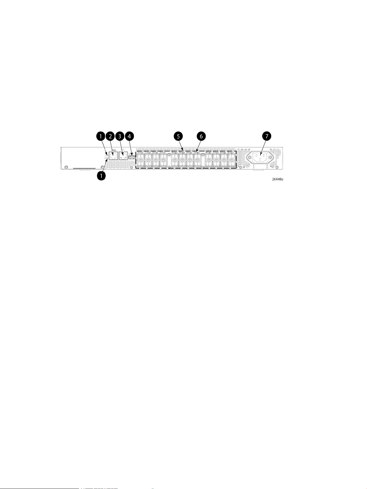
Port side of the 8/8 and 8/24 SAN Switch
The port side of the 8/8 and 8/24 SAN Switch includes the system status LED, console port,
Ethernet port, USB port, and FC ports with corresponding port status LEDs. Additionally, a pull-out
tab identifies the serial number, MAC address, and WWN. Record the switch IP address on the
pull-out tab for easy access.
Figure 1 (page 9) shows the port side of the 8/8 and 8/24 SAN Switch.
Figure 1 Port side view—8/8 and 8/24 SAN Switch
4. USB port
5. Fibre Channel status LEDs1. System status (top) and power (bottom) LEDs
6. Fibre Channel ports (24)2. System RS-232 console port (RJ-45)
7. AC power inlet3. Ethernet port with two Ethernet status LEDs
Nonport side of the 8/8 and 8/24 SAN Switch
The nonport side is used solely for airflow. The enclosure uses forced-air cooling, with the fans
pushing the air from the nonport side of the chassis through the enclosure, and exhausting to
the port side.
Activating additional 8/8 and 8/24 SAN Switch ports
By default, the 8/8 SAN Switch model integrates eight licensed ports (ports 0 through 7).
Additionally, the 8/24 SAN Switch model integrates 16 licensed ports (ports 0 through 15). To
enable additional ports, you must purchase and install the HPE Storage Works 8/8 and 8/24 SAN
Switch 8-Gb 8-port Upgrade LTU (part number T5518A):
• For the 8/8 SAN Switch—To enable ports 8 through 15, you must purchase and install one
upgrade license. To enable ports 15 through 23, you must purchase and install one upgrade
license.
• For the 8/24 SAN Switch—To enable ports 15 through 23, you must purchase and install a
second upgrade license.
See Installing and activating Port Upgrade licenses (page 20).
Enabling E_Ports on the 8/8 SAN Switch
The 8/8 SAN Switch model requires that you purchase the HPE StorageWorks Full Fabric Upgrade
License (part number T4261A) to enable E_Ports (the 8/24 SAN Switch ships with the Full Fabric
license installed).
By default, the 8/8 SAN Switch cannot be connected to another switch until this license is installed.
Without the license, the switch can still be connected directly to hosts and storage devices. To
install the Full Fabric Upgrade License, use the licenseadd command. When installed, the
8/8 and 8/24 SAN Switch features 9
Page 10
license appears under the licenseshow command as Full Fabric License and indicates
that E_Ports are now enabled automatically.
8/40 SAN Switch features
• Provides the EZSwitch Setup Wizard for easy setup and basic configuration.
• Support for 1, 2, 4, and 8 Gb/s autosensing FC switch and router ports.
• Integrates a single motherboard design with 667 MHz PowerPC 440EPx RISC CPU and
integrated peripherals which provide high performance.
• Ships FICON and FICON Cascading ready. FICON CUP is available, but requires an optional
license.
• Provides two hot-swappable, redundant integrated power supply and fan FRUs.
• Universal ports that self-configure as E_Ports, F_Ports, M_Ports, or FL_Ports. EX_Ports
are activated on a per-port basis with the optional HPE B-series 48-80 Port SAN Switch
Integrated Routing LTU.
This license provides native FCR on a per-port basis, rather than limiting routing ports to
those on a dedicated routing blade or switch. Just like traditional FCR, IR uses EX_Ports to
import and export devices between fabrics, enabling selective device sharing while
maintaining remote fabric isolation.
• Integrates a USB port that provides storage for firmware updates, output of the supportsave
command and storage for configuration uploads and downloads.
Port side of the 8/40 SAN Switch
The port side of the 8/40 SAN Switch includes the system status LED, console port, Ethernet
port and LEDs, USB port, and FC ports with corresponding port status LEDs.
Figure 2 (page 10) shows the port side of the 8/40 SAN Switch.
Figure 2 Port side view—8/40 SAN Switch
4. Ethernet port LEDs (green/amber)
5. USB port1. System status (top) and power (bottom) LEDs
6. Fibre Channel port status LED2. System RS-232 console port (RJ-45)
7. Fibre Channel port3. System Ethernet port
Nonport side of the 8/40 SAN Switch
The nonport side includes the two redundant power supply fan assemblies and the corresponding
status LEDs. Figure 3 (page 11) shows the nonport side of the 8/40 SAN Switch.
10 HPE StorageWorks 8-Gb SAN Switches
Page 11
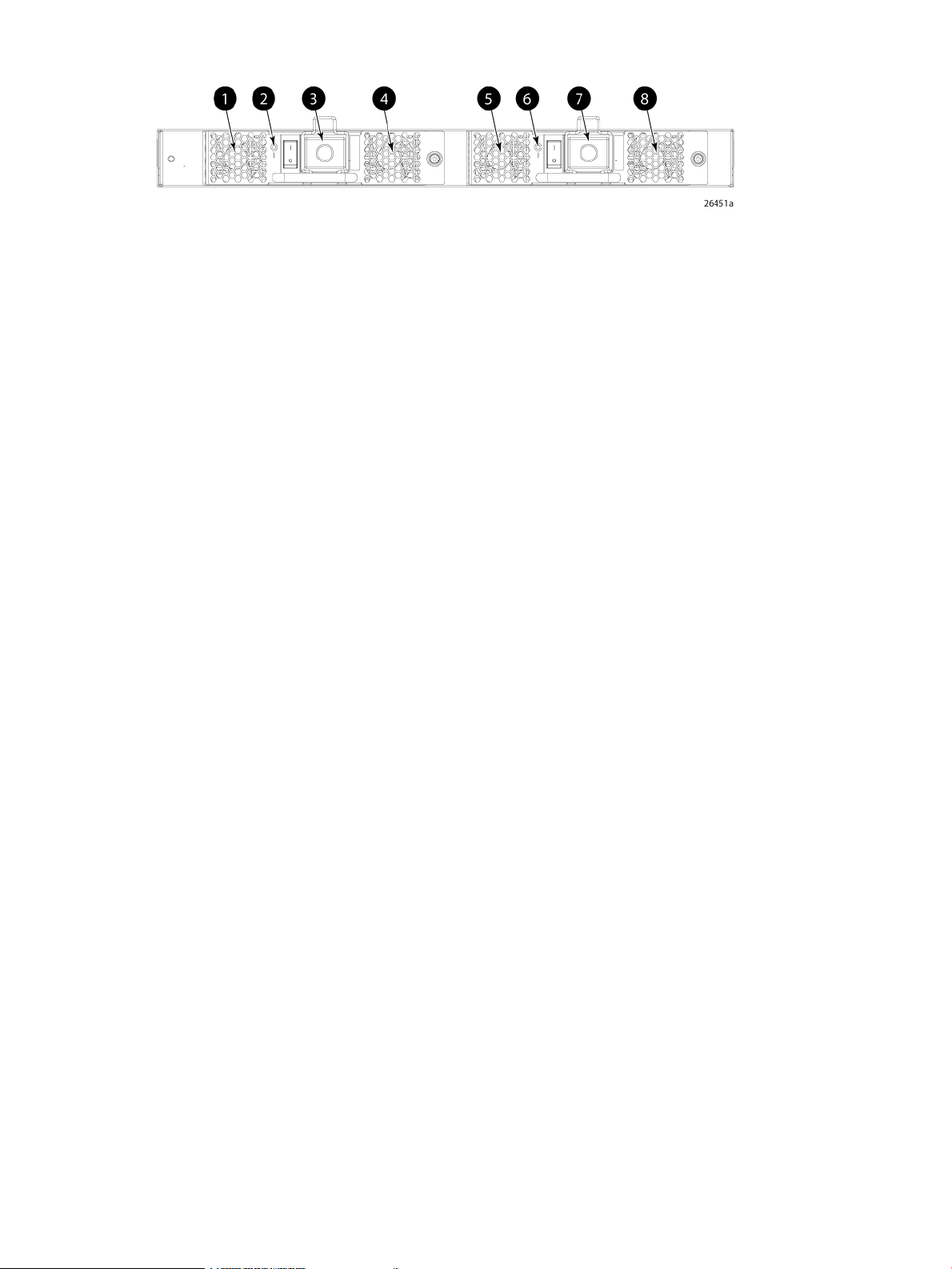
Figure 3 Nonport side view—8/40 SAN Switch
2. Power supply/fan status LED (for power supply/fan
FRU2)
Activating additional 8/40 SAN Switch ports
By default, the 8/40 SAN Switch model integrates 24 licensed ports (ports 0 through 23). To
enable additional ports, you must purchase and install the HPE Storage Works 8/40 SAN Switch
8-Gb 8-port Upgrade LTU (part number T5519A):
• To enable ports 24 through 31, you must purchase and install one upgrade license.
• To enable ports 32 through 40, you must purchase and install a second upgrade license.
5. Fan (for power supply/fan FRU1)1. Fan (for power supply/fan FRU2)
6. Power supply/fan status LED (for power supply/fan FRU
1)
7. Power supply connector (for power supply/fan FRU 1)3. Power supply connector (for power supply/fan FRU2)
8. Fan (for power supply/fan FRU1)4. Fan (for power supply/fan FRU2)
See Installing and activating Port Upgrade licenses (page 20).
8/80 SAN Switch features
• Provides the EZSwitch Setup Wizard for easy setup and basic configuration.
• Integrates 1, 2, 4, and 8 Gb/s autosensing Fibre Channel switch and router ports.
• Includes a system motherboard that features a Freescale MPC8548 RISC CPU running at
1.3 GHz with integrated peripherals that provides high performance with low power
consumption.
• Ships FICON and FICON Cascading ready. FICON CUP is available, but requires an optional
license.
• Provides two hot-swappable, redundant power supply FRUs.
• Provides three hot-swappable fan FRUs in an N+1 configuration to provide
hardware-redundant cooling.
• Provides universal ports that self-configure as E_Ports, F_Ports, M_Ports, or FL_Ports.
EX_Ports are activated on a per-port basis with the optional HPE B-series 48-80 Port SAN
Switch Integrated Routing LTU.
This license provides native FCR on a per-port basis, rather than limiting routing ports to
those on a dedicated routing blade or switch. Just like traditional FCR, Integrated Routing
uses EX_Ports to import and export devices between fabrics, enabling selective device
sharing while maintaining remote fabric isolation.
• Integrates a USB port that provides storage for firmware updates, output of the supportsave
command, and storage for configuration uploads and downloads.
Port side of the 8/80 SAN Switch
The port side of the 8/80 SAN Switch includes the system status LED, console port, Ethernet
port and LEDs, USB port, and FC ports with corresponding port status LEDs. Figure 4 (page 12)
shows the port side of the 8/80 SAN Switch.
8/80 SAN Switch features 11
Page 12
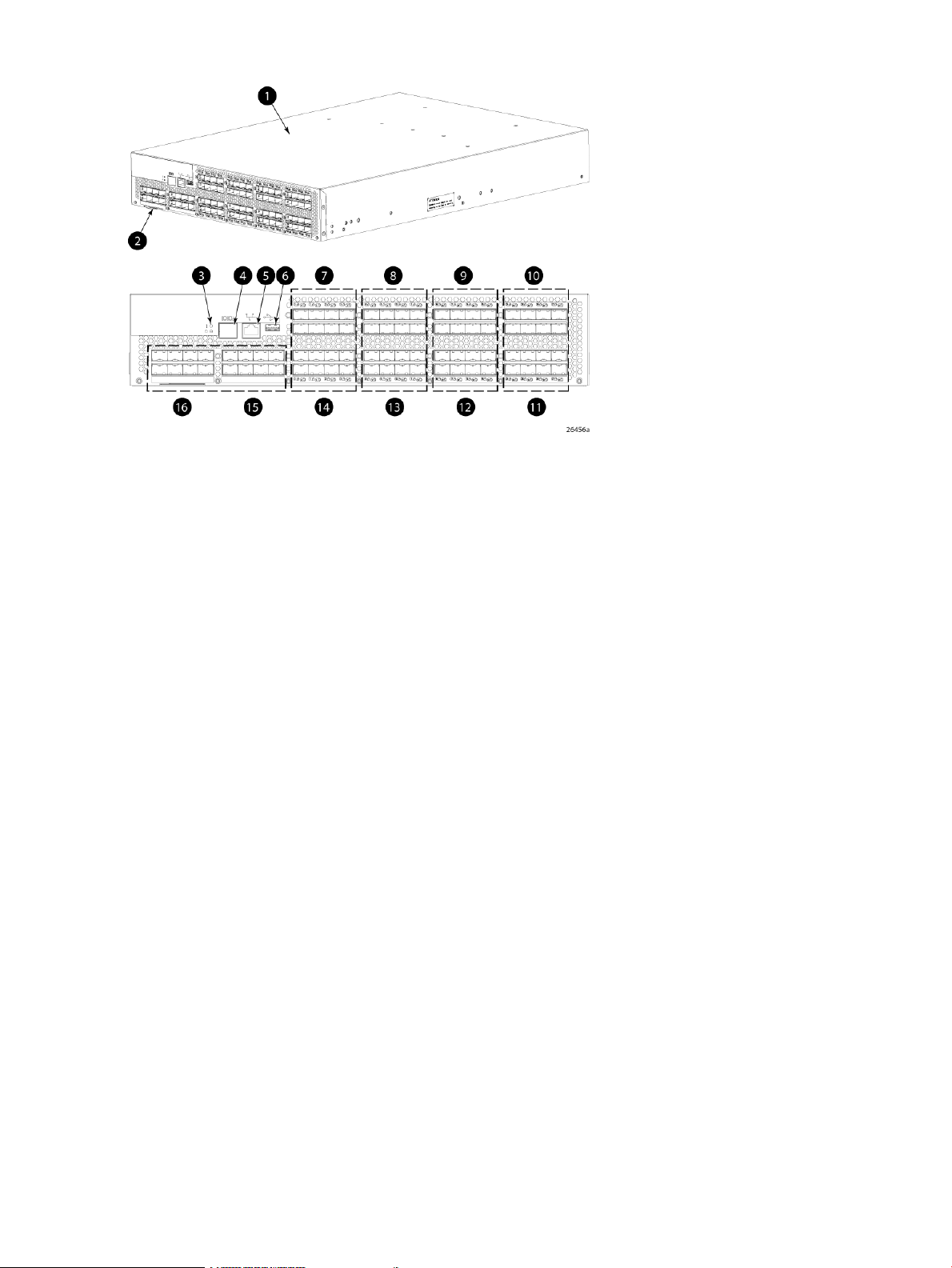
Figure 4 Port side view—8/80 SAN Switch
9. FC ports 16–231. 8/80 SAN Switch
10. FC ports 24–312. Switch ID pull-out tab
11. FC ports 32–383. Status LED (top) power LED (bottom)
12. FC ports 40–474. Console port
13. FC ports 48–555. Ethernet port
14. FC ports 56–636. USB port
15. FC ports 64–717. FC ports 0–7
16. FC ports 72–798. FC ports 8–15
Nonport side of the 8/80 SAN Switch and the Encryption SAN Switch
Figure 5 (page 13) shows the nonport side of the 8/80 SAN Switch and the Encryption SAN
Switch, which contains the power supplies (including the AC power receptacle and AC power
switch) and fans.
12 HPE StorageWorks 8-Gb SAN Switches
Page 13
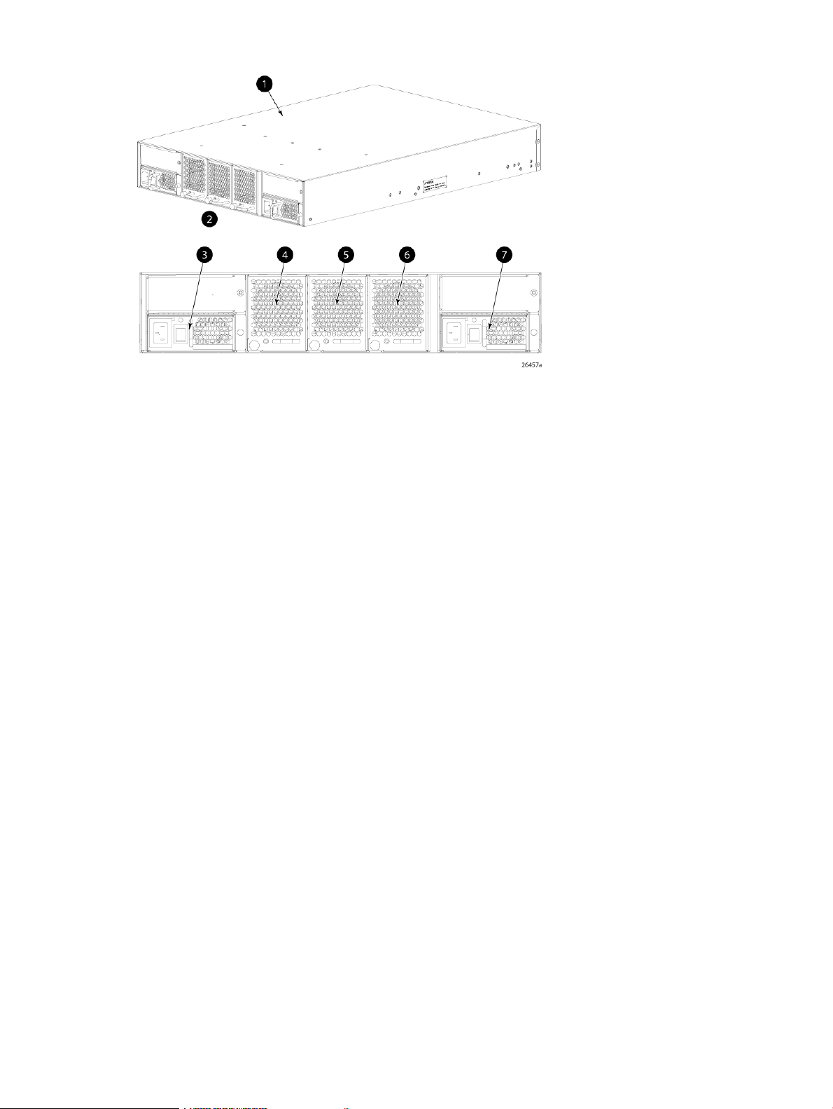
Figure 5 Nonport side view—8/80 SAN Switch
4. Fan assembly #3
5. Fan assembly #21. 8/80 SAN Switch
6. Fan assembly #12. Nonport side
7. Power supply #13. Power supply #2
Activating additional 8/80 SAN Switch ports
By default, the 8/80 SAN Switch model integrates 48 licensed ports (ports 0 through 47). To
enable additional ports, you must purchase and install the HPE StorageWorks 8/80 SAN Switch
8-Gb 16-port Upgrade LTU (part number T5520A):
• To enable ports 48 through 63, you must purchase and install one upgrade license.
• To enable ports 64 through 80, you must purchase and install a second upgrade license.
See Installing and activating Port Upgrade licenses (page 20).
Encryption SAN Switch features
The Encryption SAN Switch has the following features:
• 32 front-end 1, 2, 4, or 8 Gb/s autosensing F_Port, FL_Port, E_Port, EX_Port, or M_Ports
to connect host servers, SAN disks, SAN tapes, edge switches, or core switches
• Encryption and decryption engines to provide in-line crypto services with up to 96 Gb/s
throughput for disk I/O and up to 48 Gb/s throughput for tape I/O (mix of ciphertext and
cleartext traffic)
• Integrated with HPE SKM system
• Full 1:1 subscription on all 32 ports at 8 Gb/s
• HA cluster, DEK cluster, and EG to enable transparent failover, host MPIO failover, and
centralized management of multiple encryption switches
• Support for automatic expiry or CLI manual based re-keying
• Compliance with encryption standards: AES256-XTS 1619.1 (for disk); AES256-GCM IEEE
1619.2 (for tape)
• Smart Card
• Hardware-based key management and generation
Encryption SAN Switch features 13
Page 14

• IR Fabric Service (optional) to enable encryption capabilities across multiple fabrics
• NPIV support
• Two hot-swappable, redundant power supply FRUs
• Three hot-swappable fan FRUs in the N+1 configuration to provide hardware-redundant
cooling
• One RJ-45 10/100/1000 Ethernet management port
• Two RJ-45 GE ports for clustering interconnection and re-key, and DEK synchronization
within cluster
• One RJ-45 serial console port
• A USB port that facilitates firmware upgrades, serviceability, and system-log functionality
• A switch subsystem and encryption subsystem that features a CPU running at 1.3 GHz with
integrated peripherals that provide high performance with low power consumption
• DPS, optimizing fabric-wide performance and load balancing by automatically routing data
to the most efficient available path in the fabric
• SFP or SFP+ optical transceivers, providing support for a combination of SWL, LWL, or
ELWL optical media among the switch ports
NOTE: The full range of 1, 2, 4, and 8 Gb/s can be achieved only by a combination of 4
Gb/s SFPs (1, 2, and 4 Gb/s) and 8 Gb/s SFP+ (2, 4, and 8 Gb/s).
• Fabric OS support, delivering distributed intelligence throughout the network and enabling
a wide range of applications including Web Tools and Zoning. Optional fabric services include:
Adaptive Networking with QoS, Extended Fabrics, Enhanced Group Management, Fabric
Watch, ISL Trunking, IR, and End-to-End performance monitoring using APM.
• Extensive diagnostics and system-monitoring capabilities to enhance high RAS
• Pay as you go port and performance scalability through an Encryption Performance Upgrade
License. The base configuration provides 48 Gb/s of encryption bandwidth. The Encryption
Performance Upgrade License activates an additional 48 Gb/s bandwidth. Each switch
accepts two encryption-performance upgrades for a total of 96 Gb/s of encryption bandwidth.
The front-end user ports in the basic, first, and second levels of encryption bandwidth remain
as 32 ports at 8 Gb/s Fibre Channel.
Port side of the Encryption SAN Switch
The port side of the Encryption SAN Switch includes the status and power LEDs, smart card
reader, the RJ-45 USB, and FC ports. Figure 6 (page 15) shows the port side of the Encryption
SAN Switch.
14 HPE StorageWorks 8-Gb SAN Switches
Page 15

Figure 6 Port side of the Encryption SAN Switch
FCoE Converged Network Switch features
The FCoE Converged Network Switch has the following features:
• Includes a system motherboard with a Freescale MPC8548 RISC CPU running at 1.3 GHz
and integrated peripherals, that provides high performance with low power consumption
5. RJ-45 management port1. Status LED
6. RJ-45 serial console port2. Power LED
7. USB port3. RJ-45 GE ports (for clustering and re-keying)
8. Fibre Channel ports (0–31)4. Smart Card reader
• Contains an RJ-45 Ethernet management port and EZSwitch Setup, which supports switch
IP address discovery and configuration
• Integrates a USB port that provides storage for firmware updates, as well as supportsave
command output and configuration uploads and downloads
• Provides two hot-swappable, redundant power supply FRUs
• Provides three hot-swappable fan FRUs in an N+1 configuration to provide
hardware-redundant cooling
• Includes universal ports that self-configure as E_Ports, F_Ports, M_Ports, or FL_Ports
• Provides extensive diagnostics and system-monitoring capabilities for enhanced RAS
• Provides FCoE-to-FC latency of 1,670 ns
The FCoE Converged Network Switch has the following Ethernet capabilities:
• Contains 24 ports, 10-GbE CEE
• Provides low-latency, lossless, deterministic interconnect required for FCoE
• Provides FCoE support with FPMA discovery. Fabric OS also enables support for
Priority-based Flow Control (802.1Qbb)
• Includes DCBX - Capabilities Exchange and Enhanced Transmission Selection (802.1Qaz)
to meet the lossless and deterministic FCoE requirement
• Enables hardware-assisted MAC learning and aging
• Support for 32,768 MAC addresses and 4,096 VLANs
• Support for Layer 2 protocols STP/MSTP/RSTP (802.1q) and Link Aggregation (802.1ad)
• Hewlett Packard Enterprise branded 10-Gb SFP+ (SR and LR) and active copper cables
• Provides CEE port to CEE port latency of 570 ns (same ASIC) and 1,050 ns (different ASIC)
FCoE Converged Network Switch features 15
Page 16
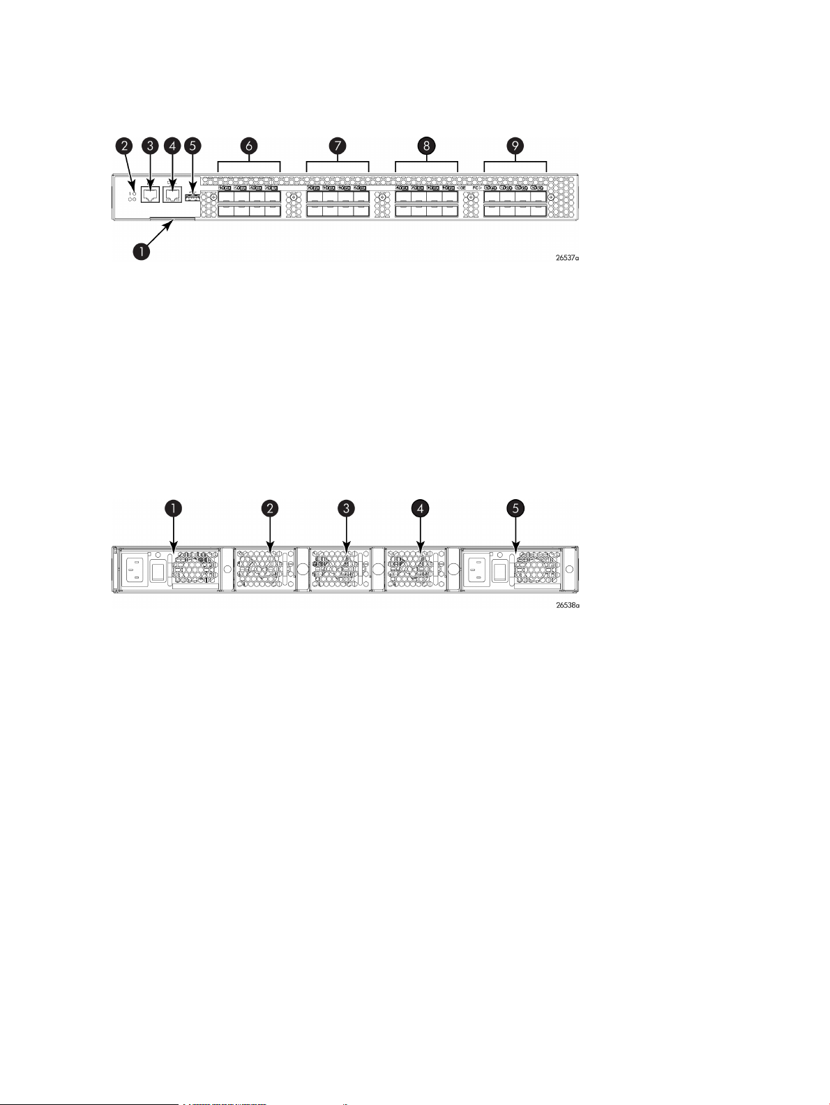
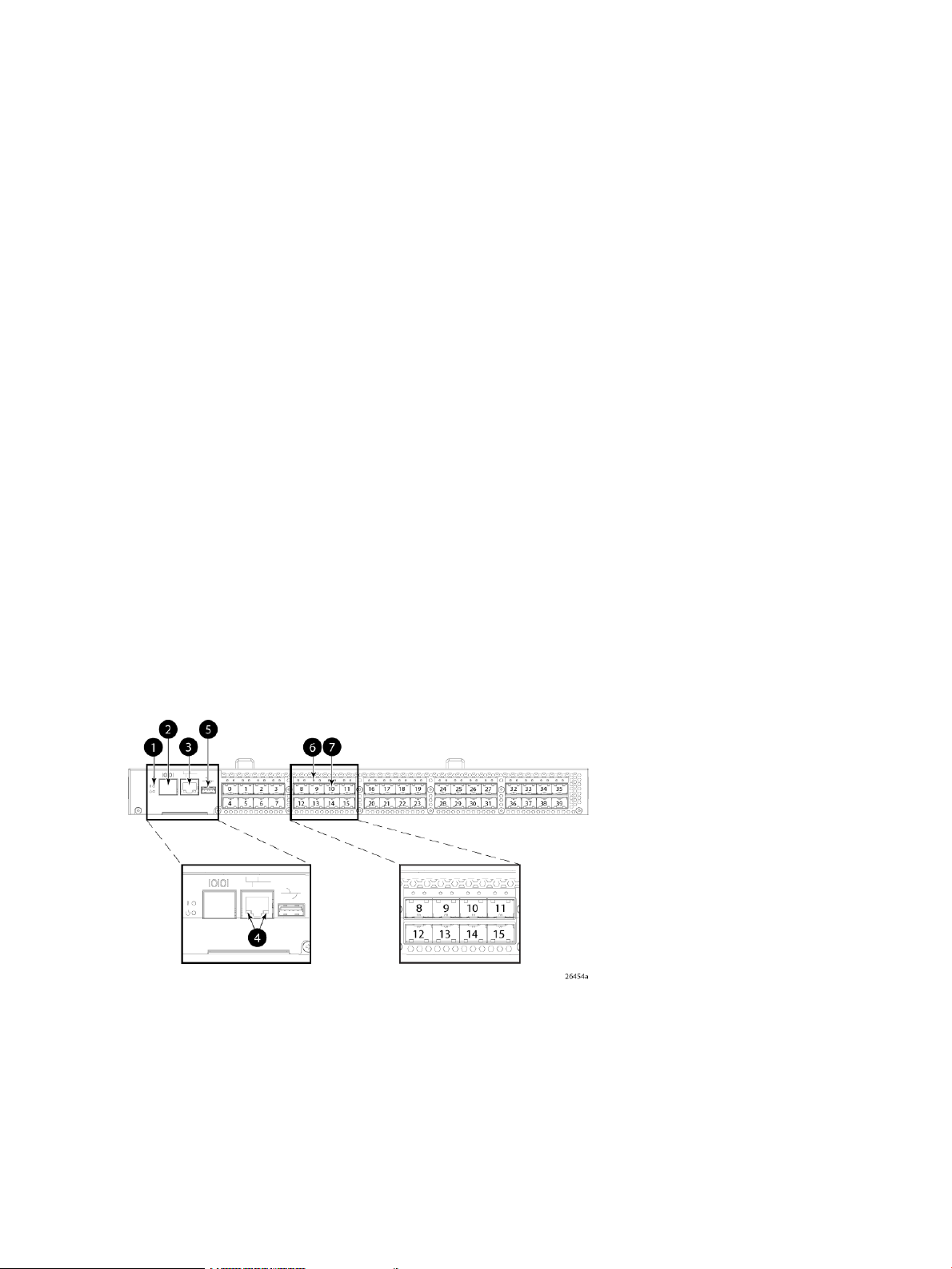
Port side of the FCoE Converged Network Switch
Figure 7 (page 16) shows the port side of the FCoE Converged Network Switch.
Figure 7 Port side of the FCoE Converged Network Switch
6. 10-GbE ports 0–71. Switch ID pull-out tab
7. 10-GbE ports 8–152. System status (top) and power (bottom) LEDs
8. 10-GbE ports 16–233. Serial console port
9. FC ports 0–74. Management Ethernet port
5. USB port
Nonport side of the FCoE Converged Network Switch
Figure 8 (page 16) shows the nonport side of the FCoE Converged Network Switch.
Figure 8 Nonport side of the FCoE Converged Network Switch
3. Fan assembly #2
1606 Extension SAN Switch features
A fully licensed 1606 Extension SAN Switch has the following features:
• FCIP capability
Includes up to eight FCIP tunnels.◦
◦ Each FCIP tunnel is represented and managed as a VE_Port.
◦ Fibre Channel Routing Services can be used over the FCIP link.
4. Fan assembly #11. Power supply #2
5. Power supply #12. Fan assembly #3
◦ Fabrics connected through FCIP merge if the ports are configured as VE_Ports, and
do not merge if one end of the connection is configured as a VEx_Port. If VE_Ports are
used in a Fibre Channel Routing Services backbone fabric configuration, then the
backbone fabric merges but the EX_Ports attached to edge fabrics do not merge. For
more information, see the Fabric OS Administrator’s Guide.
• FCIP Trunking with load balancing and network-based failure recovery
16 HPE StorageWorks 8-Gb SAN Switches
Page 17

• Adaptive Rate Limiting
Configurable minimum and maximum committed bandwidth per FCIP tunnel◦
◦ Minimum rate is guaranteed rate
• FC Frame Compression before FCIP Encapsulation
• FCR
• SOTCP with reorder resistance
• FastWrite over FCIP (not over FC)
• Open Systems Tape Pipelining over FCIP
• FCIP QoS
• TCP Performance Graphing in Web Tools
• FICON and FICON Cascading ready.
• FICON CUP (requires an optional license).
• FICON Accelerator for IBM TotalStorage z/OS Global Mirror (aka, XRC) and FICON Tape
(requires an optional license).
The 1606 Extension SAN Switch has the following hardware features:
• Up to 16 Fibre Channel SFP ports supporting Fibre Channel Switching or Fibre Channel
Routing Services, with link speeds of 1-, 2-, 4-, or 8-Gb/s
• Up to 6 1-GbE ports supporting the FCIP and Fibre Channel Routing Services features, with
transmit link speeds of up to 1-Gb/s on each port
Two ports (ge0 and ge1) can be configured for use with either copper or optical cables
• Rack–mountable 1U chassis
• Two PowerPC 440EPx processors running at 667 MHz
• One GoldenEye2 switch ASIC for 1, 2, 4, or 8 Gb/s FC switching
• One Cavium CN5740 running with 8 MIPS cores at 750 MHz for data path processing
• One Blaster FPGA for FC compression, offloads such as chksum generation/checks
• One 10/100/1000 Base-T Ethernet port for the management interface
• One RJ-45 terminal port
• One USB port for storing firmware updates, supportSave command output, and
configuration uploads and downloads
• Two redundant, hot-swappable combined power supply/fan assembly FRUs
• Five internal temperature sensors
Feature comparison of base and upgraded products
Table 1 (page 17) compares the features supported on the base and fully upgraded 1606
Extension SAN Switch. It also lists the optionally licensed features.
Table 1 Comparison of 1606 Extension SAN Switch features
1606 Extension SAN Switch features 17
With upgrade licenseBase productFeature
164Number of Fibre Channel ports
62Number of GbE ports
Page 18

Table 1 Comparison of 1606 Extension SAN Switch features (continued)
With upgrade licenseBase productFeature
Fibre Channel Routing between
remote fabrics for fault isolation
FCIP Trunking
Adaptive Rate Limiting
FCIP Tunnel
1
Requires Integrated Routing license
2
Requires Advanced Extension license
Yes
Yes
Yes
1
2
2
Yes
YesYesFCIP Tunnel
82Number of FCIP tunnels
Yes
Yes
YesYesFC Frame Compression
YesYesSOTCP
YesYesFastWrite over FCIP Tunnel
YesNoOpen Systems Tape Pipelining over
1
2
2
• Before installation of the upgrade license, any ports other than the basic four FC ports and
two GbE ports are shown as Disabled when you execute the switchshow command.
• On the base 1606 Extension SAN Switch, you can configure the two GbE ports (ge0 and
ge1) for use with either copper or optical cables (physically separate ports are provided).
• FC frame compression is not the same as IP compression and is disabled by default. To
enable FC frame compression use the portCfg command. For more information, see the
Fabric OS Administrator’s Guide.
• FCIP tunnel bandwidth has a minimum rate of 1,544 Kb/s (the T1 rate). Configuration requests
with lower rates are rejected.
• FCIP Trunking is available to virtualize two or more IP address pairs (circuits) as part of a
single FCIP tunnel. You can configure up to four circuits for a single FCIP tunnel. For more
information on configuring circuits, see the Fabric OS Administrator’s Guide.
• Multiple FCIP tunnels can share the same GbE port. VE_Ports and VEx_Ports are not
associated with a single physical GbE port.
Available licenses
The following features are available with the purchase of a license key for the 1606 Extension
SAN Switch:
• Advanced Extension
• IR
• Extended Fabric
• Adaptive Networking
• Server Application Optimization
• ISL Trunking
• Fabric Watch
• Advanced Performance Monitor
18 HPE StorageWorks 8-Gb SAN Switches
Page 19
• FICON CUP
• FICON Accelerator
For information on these features, see the Fabric OS Administrator’s Guide.
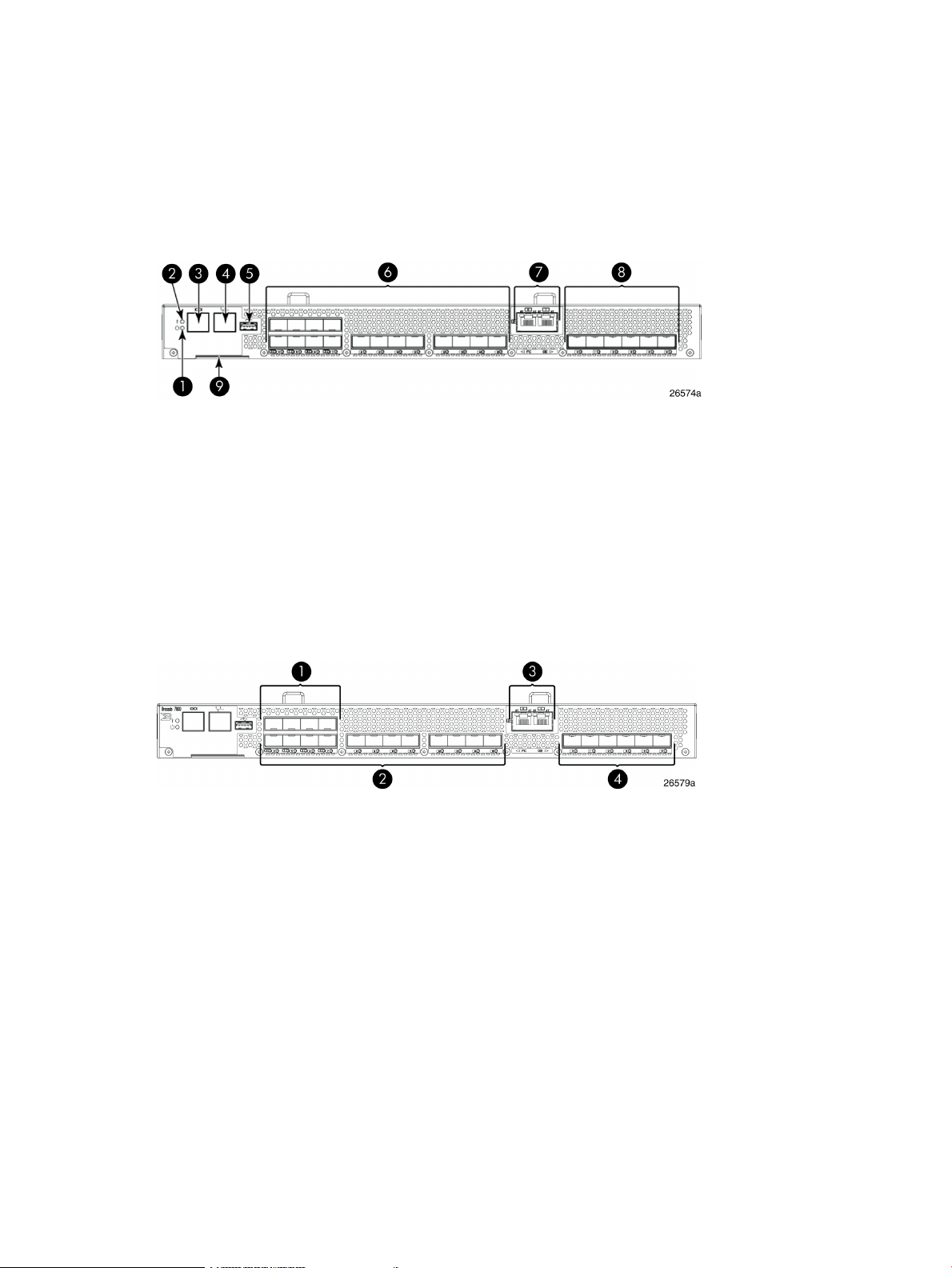
Port side of the 1606 Extension SAN Switch
Figure 9 (page 19) shows the components on the port side of the 1606 Extension SAN Switch.
Figure 9 Port side of the HPE 1606 Extension SAN Switch
5. USB port
6. Fibre Channel ports (16)1. System power LED
7. GbE ports: copper RJ45(2)2. System status LED
8. GbE ports: optical SFP (6)3. Console port (RJ45)
9. Serial number pull-out tab4. Ethernet management port
The Fibre Channel ports are numbered from left to right on the faceplate, as shown in
Figure 10 (page 19).
Figure 10 Port numbering on the 1606 Extension SAN Switch
3. GbE ports: ge0-ge1 (copper only)1. Fibre Channel ports 0–3
4. GbE ports: ge0–ge5 (SFP)2. Fibre Channel ports 4–15
A fully licensed 1606 Extension SAN Switch can have two trunking groups. Group 1 consists of
Fibre Channel ports 0–7, and group 2 consists of Fibre Channel ports 8–15.
Nonport side of the 1606 Extension SAN Switch
Figure 11 (page 20) shows the nonport side of the 1606 Extension SAN Switch, which contains
the combined power supplies and fans.
1606 Extension SAN Switch features 19
Page 20

Figure 11 Nonport side of the 1606 Extension SAN Switch
7. Fan assembly 11. Fan and power supply assembly #2
8. FRU LED2. Fan and power supply assembly #1
9. Power supply #13. Fan assembly #2
10. Fan assembly #14. FRU LED
11. FRU handle5. Power supply #2
12. FRU handle6. Fan assembly #2
Installing and activating Port Upgrade licenses
1. Use the portshow command to verify the number of ports licensed on your switch. The
port status output indicates Started and Licensed for enabled ports. For more information
on this command, see the Fabric OS Command Reference Manual.
2. Obtain the WWN from the Switch ID pull-out tab located on the port side of your switch.
Alternately, you can use the switchshow command to display the WWN.
3. Contact your Hewlett Packard Enterprise representative to purchase the appropriate Port
Upgrade license. Hewlett Packard Enterprise requires the switch WWN obtained in Step 2
to assign a license key.
4. Install the license:
a. Log in to the switch as admin.
b. Issue the licenseadd command, followed by the license key enclosed in quotation
marks. (The license key consists of approximately 16 uppercase and lowercase letters
and numerals.)
IMPORTANT: Enter the license key exactly as issued. If you enter the key incorrectly,
the license will not function properly.
c. Enter the licenseshow command to verify that the license is valid. If a licensed product
is not displayed, the license is not valid.
NOTE: It is not necessary to reboot the system.
5. Configure the inactive ports. Enter the portstart command to start the ports. This command
loads the port code, unlike the portenable command, which enables the port laser. For
example:
portstart 16–31
6. Enter the portenable command to enable the ports. For example:
portenable 16–31
7. (Optional) Enter the portshow command to verify that the newly activated ports are started.
SAN Switch ISL Trunking groups
All 8-Gb SAN Switch models support ISL Trunking as an optional, licensed feature for FC ports.
When this feature is enabled, trunked groups of up to eight contiguous ports are created.
20 HPE StorageWorks 8-Gb SAN Switches
Page 21
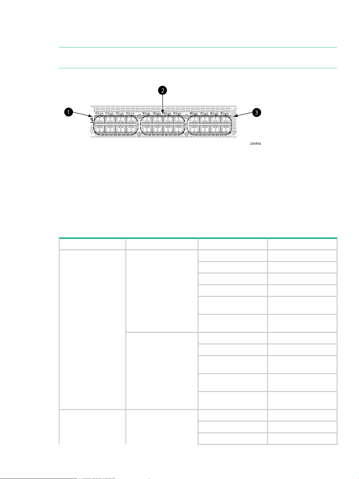
For example, the Fibre Channel ports on the SAN Switch are numbered from left to right and
color-coded into groups of eight to indicate which ports you can combine into trunked groups.
Figure 12 (page 21) shows the 8/8 SAN Switch with three trunked groups of eight ports.
NOTE: If your 8-Gb SAN Switch is licensed for ISL Trunking (for example, Power Pack+ models
ship with this license), use the trunking groups available on the switch.
Figure 12 Trunking groups example
3. Trunk group 3: Ports 16–231. Trunk group 1: Ports 0–7
2. Trunk group 2: Ports 8–15
For more information about trunking, see the Fabric OS Administrator's Guide for the firmware
version you are running.
Supported SFP transceiver options
Table 2 (page 21) lists the only SFPs supported in your HPE StorageWorks 8-Gb SAN Switches.
Table 2 Supported SFP transceiver options
SFP
8Gb/s extended long wave
SFP
cable
cable
Part numberOptionPort typeSwitch product
AJ716A8Gb/s short wave SFP+Fibre Channel2408 FCoE switch
AJ717A8Gb/s long wave SFP+
AJ715A4Gb/s short wave SFP
AK870A4Gb/s long wave SFP
AN211A4Gb/s extended long wave
AW538A
AP823A10GbE short range SFP+10GbE CEE ports
AP824A10GbE long range SFP+
AP818A1m active copper SFP+
AP819A3m active copper SFP+
cable
AP820A5m active copper SFP+
AJ716A8Gb/s short-wave SFP+Fibre Channel1606 Extension switch
AJ717A8Gb/s long-wave SFP+
AJ715A4Gb/s short-wave SFP
Supported SFP transceiver options 21
Page 22

Table 2 Supported SFP transceiver options (continued)
SFP
Part numberOptionPort typeSwitch product
AK870A4Gb/s long-wave SFP
AN211A4Gb/s extended long-wave
8-Gb SAN Switch software options
The following optional software kits and licenses are available. More information on these products
is include in the product QuickSpecs, which can be accessed from the Hewlett Packard Enterprise
website:
http://h18006.www1.hp.com/storage/networking/b_switches/san/index.html
8Gb/s extended long-wave
SFP
SFP
SFP
8Gb/s extended long-wave
SFP
AW538A
AJ715A4Gb/s short-wave SFP1GbE FCIP ports
AK870A4Gb/s long-wave SFP
AN211A4Gb/s extended long-wave
AW537A1GbE copper SFP
AJ716A8Gb/s short-wave SFP+Fibre Channel8Gb SAN Switches
AJ717A8Gb/s long-wave SFP+
AJ715A4Gb/s short-wave SFP
AK870A4Gb/s long-wave SFP
AN211A4Gb/s extended long-wave
AW538A
• HPE StorageWorks Full Fabric Upgrade License
• HPE StorageWorks 8/8 and 8/24 SAN Switch 8-Gb 8-port Upgrade LTU
• HPE StorageWorks 8/80 SAN Switch 8-Gb 16-port Upgrade LTU
• HPE StorageWorks 8/40 SAN Switch 8-Gb 8-port Upgrade LTU
• Adaptive Networking
• Fabric Watch
• ISL Trunking
• APM
• Extended Fabric
• HPE B-series 48-80 Port SAN Switch Integrated Routing LTU (purchase for 8/80 SAN Switch
only)
• Data Center Fabric Manager Professional Plus (4 fabrics, 2560 switch ports)
• Data Center Fabric Manager Enterprise (24 fabrics, 9000 switch ports)
• HPE Encryption SAN Switch Performance Upgrade LTU
• HPE StorageWorks 1606 Switch Upgrade to Full LTU
22 HPE StorageWorks 8-Gb SAN Switches
Page 23

• HPE StorageWorks Extension SAN Switch Advanced LTU
• HPE StorageWorks 1606 Extension SAN Switch FICON Control Unit Port LTU
• HPE StorageWorks 1606 Extension SAN Switch Integrated Routing LTU (purchase for 1606
Extension SAN Switch only)
• HPE 1606 Switch FICON CUP Accelerator LTU
• HPE StorageWorks Power Pack Upgrade
• SAO
• HPE B-series 24-40 Port SAN Switch Integrated Routing LTU (purchase for 8/40 SAN Switch
only)
8-Gb SAN Switch hardware options
Table 3 (page 23) lists the optional hardware kits.
Table 3 Optional hardware kits
OM2 LC-LC type cables
Order numberHardware kit
AK864AHPE StorageWorks 2-Gb USB Device
221692-B212 m LC-to-LC multi-mode FC cable
OM3 LC-LC type cables
LC-SC for between a 1-Gb and a 2-Gb device
221692-B225 m LC-to-LC multi-mode FC cable
221692-B2315 m LC-to-LC multi-mode FC cable
221692-B2630 m LC-to-LC multi-mode FC cable
221692-B2750 m LC-to-LC multi-mode FC cable
AJ833A0.5 m LC-LC multi-mode OM3 FC cable
AJ834A1 m LC-LC multi-mode OM3 FC cable
AJ835A2 m LC-LC multi-mode OM3 FC cable
AJ836A5 m LC-LC multi-mode OM3 FC cable
AJ837A15 m LC-LC multi-mode OM3 FC cable
AJ838A30 m LC-LC multi-mode OM3 FC cable
AJ839A50 m LC-LC multi-mode OM3 FC cable
221691-B212 m LC-SC multi-mode FC cable
221691-B225 m LC-SC multi-mode FC cable
221691-B2315 m LC-SC multi-mode FC cable
221691-B2630 m LC-SC multi-mode FC cable
221691-B2750 m LC-SC multi-mode FC cable
NOTE: For the latest information on hardware and software components, see the B-series
Switches section of the HPE Storage Networking website: http://www.hpe.com/go/san.
8-Gb SAN Switch hardware options 23
Page 24
2 Installing and configuring an 8-Gb SAN Switch
This chapter provides information about and instructions to install and configure an 8-Gb SAN
Switch.
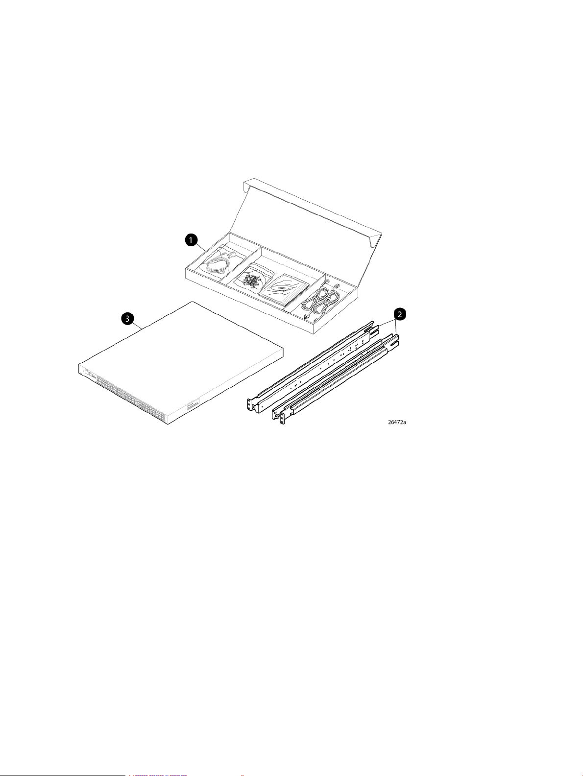
Shipping carton contents
Figure 13 (page 24) and Table 4 (page 25) identify shipping carton contents for a typical 8-Gb
SAN Switch. The shipping configuration for your model can vary.
Figure 13 8/40 SAN Switch shipping carton contents
1. Accessory kit
2. Rails
3. Switch
24 Installing and configuring an 8-Gb SAN Switch
Page 25

Table 4 8-Gb SAN Switch shipping carton contents
Description
One accessory kit, containing the following items:
• HPE StorageWorks product documentation:
HPE StorageWorks 8-Gb SAN Switch Quick Start Instructions◦
◦ HPE StorageWorks SAN Switch Rack Mount Kit Installation Instructions
◦ Read Me First
◦ Safety Guides
◦ User License
◦ Warranty
• A serial cable, approximately 3 m (10 ft.)
• Plenum (not shown) ships in your switch accessory kit only if required for installing your switch in an HPE custom
rack. For more information, see the HPE StorageWorks SAN Switch Rack Mount Kit Installation Instructions. The
plenum is an air duct that attaches to the SAN Switch Rack Mount Kit switch rails.
• Four rubber feet for mounting on a flat surface (a lab bench, for example)
• EZSwitch Setup CD
• One or two grounded power cords, as required for your particular switch
• PDU power cords, as required for your particular switch
SAN Switch Rack Mount Kit hardware and rail assemblies:
• Two rear mounting brackets
• A right inner rail and a right outer rail
• A left inner rail and a left outer rail
One 8-Gb SAN Switch, including power supply and fan assembly units
Installation and safety considerations
You can install the switch in a rack or as a standalone device on a flat surface.
Hewlett Packard Enterprise highly recommends mounting the switch in one of the following
Hewlett Packard Enterprise customized racks:
• HPE System/e Rack
• HPE 10000 Series Rack
Electrical considerations
For successful installation and operation of the switch, ensure that the following electrical
requirements are met:
• The primary outlet is correctly wired, protected by a circuit breaker, and grounded in
accordance with local electrical codes.
• The supply circuit, line fusing, and wire size are adequate, as specified by the electrical
rating on the switch nameplate.
• A minimum of 79.8 cubic meters/hour (47 cubic feet/minute) of airflow is available to the air
intake vents on the nonport side of the switch.
• The power supply standards provided in Power supply specifications (page 75), are met.
Installation and safety considerations 25
Page 26

Environmental considerations
Before installing the switch, verify that the following environmental requirements are met:
• Install the switch with the nonport side, which contains the air intake vents, facing the cool-air
aisle.
• All equipment in the rack forces air in the same direction, to avoid taking in exhaust air.
• A minimum of 24 cubic ft/min of airflow is available to the air intake vents on the nonport
side of the switch.
• The ambient air temperature does not exceed 40°C (104°F) while the switch is operating.
IMPORTANT: The 40ºC value applies to the ambient air temperature at the air intake vents
on the nonport side of the switch. The temperature inside the switch can be up to 80ºC (176ºF)
during switch operation. If the internal temperature range exceeds the operating ranges of the
components, the LEDs, error messages, and Fabric Watch alerts indicate a problem. Enter the
tempshow or fabric watch command to view the temperature status.
Rack mount considerations
If you are installing the switch in a rack, verify that the following requirements are met:
• The cabinet or rack must be a standard EIA cabinet.
• Plan rack mount space that is 1 U high, and 48.3 cm (19 inches) wide. One U is 4.45 cm
(1.75 inches).
• Ground all equipment in the cabinet through a reliable branch circuit connection, and maintain
ground at all times. Do not rely on a secondary connection to a branch circuit, such as a
power strip.
• Ensure that airflow and temperature requirements are met on an ongoing basis, particularly
if the switch is installed in a closed or multirack assembly.
• Verify that the additional weight of the switch does not exceed the cabinet’s weight limits.
• Secure the rack to ensure stability in case of unexpected movement, such as an earthquake.
Cabling considerations
NOTE: Cables can be organized and managed in a variety of ways: for example, using cable
channels on the sides of the cabinet or patch panels to minimize cable management.
Before installing the switch, plan for cable management based on the following Hewlett Packard
Enterprise recommendations:
• Leave enough space to allow for the fact that the minimum bend radius for a 50-micron cable
is 5 cm (2 inches) under full tensile load and 3 cm (1.2 inches) with no tensile load.
• Leave at least 1 m (3.28 ft) of slack for each port cable. This provides room to remove and
replace the switch, allows for inadvertent movement of the rack, and helps prevent the cables
from being bent to less than the minimum bend radius.
• If you are using ISL Trunking, consider grouping cables by trunking groups. The cables used
in trunking groups must meet specific requirements, as described in the Fabric OS
Administrator's Guide.
• For easier maintenance, label the fiber optic cables, and record the devices to which they
are connected.
26 Installing and configuring an 8-Gb SAN Switch
Page 27

• Keep LEDs visible by routing port cables and other cables away from the LEDs.
CAUTION: Do not use tie wraps on fiber optic cables because wraps are easily
overtightened and can damage the optical fibers.
• Use Velcro straps to secure and organize fiber optic cables.
Items required for installation
Obtain the following:
• 8-Gb SAN Switch installed and connected to a power source
• A workstation with an installed terminal emulator, such as HyperTerminal
• Unused IP address and corresponding subnet mask and gateway address
• Serial cable (supplied with switch)
• Ethernet cable
• SFP transceivers and compatible cables, as required
NOTE: For FCoE Converged Network Switches, both HPE-branded FC SFPs and CEE
10-GbE SFPs are required. FC SFP+ transceivers are required for 8-Gb/s performance;
copper cables must be HPE-branded.
• Access to an FTP server to back up the switch configuration (optional)
Installing the switch as a standalone device
To install the switch as a standalone unit:
1. Unpack the switch, and verify that all items listed in Shipping carton contents (page 24) are
present.
2. Locate the four rubber feet in the accessory box.
3. Apply the adhesive rubber feet to the switch. The rubber feet help prevent the switch from
sliding off the supporting surface.
a. Clean the indentations at each corner of the bottom of the switch to ensure that they
are free of dust or other debris that can lessen the adhesion of the feet.
b. With the adhesive side against the chassis, place one rubber foot in each indentation
and press into place.
4. Place the switch on a flat, sturdy surface.
5. Apply power to the switch as described in Powering on the 8-Gb SAN Switch (page 38).
CAUTION: Do not connect the switch to the network until the IP address is set. See Setting
the switch IP address (page 39).
Installing the switch using the SAN Switch Rack Mount Kit
This section describes the use of the SAN Switch Rack Mount Kit (part number A7511A) ro rack
mount SAN switches and routers.
Use the SAN Switch Rack Mount Kit for installations in the following HPE StorageWorks custom
racks only:
• HPE 9000 Series Rack
• HPE 10000 Series Rack
Items required for installation 27
Page 28

• HPE 10000 G2 Series Rack
• HPE System/e Rack
NOTE: In this document, “HPE 10000 Series Rack” refers to both the HPE 10000 Series Rack
and the HPE 10000 G2 Series Rack.
Supported devices
Use the SAN Switch Rack Mount Kit to install the following switch models:
• SAN Switch 2/8V
• SAN Switch 2/8
• SAN Switch 2/8-EL
• SAN Switch 2/16V
• SAN Switch 2/16
• SAN Switch 2/16N
• SAN Switch 2/32
• SAN Switch 4/32
• SAN Switch 4/32B
• 4/8 SAN Switch
• 4/16 SAN Switch
• 4/64 SAN Switch
• 8/8 SAN Switch
• 8/24 SAN Switch
• 8/40 SAN Switch
• 8/80 SAN Switch
• 1606 Extension SAN Switch
• FCoE Converged Network Switch
• Encryption SAN Switch
• Multiprotocol (MP) Router
• 400 Multiprotocol (MP) Router
Related documentation
For the latest B-series switch product documentation, see the storage section on the Hewlett
Packard Enterprise website:
http://www.hp.com/support/manuals
Before you begin—Important information about the plenum
The plenum is an air duct that attaches to the switch rails, enabling the switch to draw cooler air
into the switch from outside the rack, rather than drawing in heated air from within the rack.
A plenum ships with the following 8–Gb SAN Switch models only:
• SAN Switch 2/8V
• SAN Switch 2/8
28 Installing and configuring an 8-Gb SAN Switch
Page 29

• SAN Switch 2/16V
• 4/8 SAN Switch
• 4/16 SAN Switch
• 4/32B SAN Switch
• 8/8 SAN Switch
• 8/24 SAN Switch
See (page 36) for instructions on installing the plenum.
Installation and safety guidelines
Verify that the rack and the area around the rack meet the following requirements:
• Plan a rack space that is 1.5 units high (6.7 cm or 2.6 inches), 48.3 cm (19 inches) wide,
and at least 68.6 cm (23 inches) deep. For the MP Router, 4/64 SAN Switch, or 8/80 SAN
Switch, and Encryption SAN Switch, plan a rack space that is at least 2 units high.
• Ground all equipment in the rack through a reliable branch circuit connection, and maintain
ground at all times. Do not rely on a secondary connection to a branch circuit, such as a
power strip.
• Ensure that airflow and temperature requirements are met on an ongoing basis.
• Secure the rack to ensure stability in case of unexpected movement.
Installing the switch using the SAN Switch Rack Mount Kit 29
Page 30
Installing the HPE SAN Switch Rack Mount Kit in your Hewlett Packard Enterprise custom rack
The SAN Switch Rack Mount Kit enables you to install your Hewlett Packard Enterprise device
in the following Hewlett Packard Enterprise custom racks:
• HPE System/e Rack
• HPE 10000 Series rack
For optimal cable management, Hewlett Packard Enterprise recommends that you install the
SAN Switch Rack Mount Kit to allow the nonport side of the device to slide out of the cool-air
side of the rack. In this installation, the port side of the switch is set back from the edge of the
rack, allowing a more gradual bend in the fiber optic cables.
NOTE: The SAN Switch Rack Mount Kit installation requires one technician.
The following items are required to install the switch in a rack:
• Power cables
• A #2 Phillips screwdriver
• A 7/16-inch wrench or socket
• Plenum (if required)
See “Before you begin—Important information about the plenum” (page 28) to determine
whether you need to install a plenum before rack mounting your device.
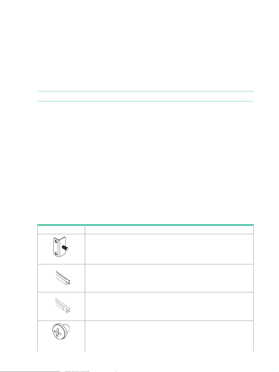
• SAN Switch Rack Mount Kit hardware, listed in Table 5 (page 30)
Table 5 (page 30) identifies the rails and rail-mounting hardware.
Depending on your configuration, one of the following devices may be required:
• SAN Switch or MP Router
• FCoE Converged Network Switch
• Encryption SAN Switch
Table 5 SAN Switch Rack Mount Kit hardware
DescriptionItem
Two rear mounting brackets
A right inner rail and a right outer rail
A left inner rail and a left outer rail
Fourteen #8-32 x 3/16-inch Phillips panhead screws with thread lock for use with the SAN
Switch 2/32 only.
Fourteen #8-32 x 5/16-inch Phillips panhead SEMS screws for use with the 4/8, 4/16, 4/32,
4/64 SAN and 4/32B SAN Switches, and the 2/16, 2/8V, 2/16V, MP Router, 400 MP Router,
8/8, 8/24, 8/40, 8/80, and FCoE Converged Network Switch
30 Installing and configuring an 8-Gb SAN Switch
Page 31

Table 5 SAN Switch Rack Mount Kit hardware (continued)
DescriptionItem
NOTE: All devices require 10 screws except for the 4/32B SAN Switch, MP Router,
Encryption SAN Switch, and FCoE Converged Network Switch, which require only 6 screws.
Ten #10-32 x 1/2-inch Phillips panhead screws with captive star lock washers
Eight #10 alignment washers
Eight #10 adapter washers
Two 1/4-20 hex nuts with captive star lock washers
Two 1/4-inch flat washers
CAUTION: For proper airflow, the SFP+ media side of the device port side must face the rear
of the rack. This allows air to enter the front of the rack and exit from the rear.
To install the device in a rack:
1. Verify that the required parts and hardware are available. (See Table 5 (page 30).)
2. Choose a mounting location for the device in the rack.
3. Attach the rear mounting brackets to the rear rack uprights.
• For an HPE 10000 Series Rack, assemble each of the brackets using two #10-32 x
1/2-inch Phillips panhead screws with captive star lock washers and two #10 adapter
washers, as shown in Figure 14 (page 32).
• For an HPE System/e Rack, install the two rear mounting brackets using two #10-32 x
1/2-inch Phillips panhead screws and two #10 alignment washers, as shown in
Figure 15 (page 32).
Installing the switch using the SAN Switch Rack Mount Kit 31
Page 32

Figure 14 Installing the rear mounting brackets (HPE 10000 Series rack)
Figure 15 Installing the rear mounting brackets (HPE System/e rack)
NOTE: The SAN Switch Rack Mount Kit contains rails labeled Left and Right to designate
the left side and right side of the cabinet as viewed from the front of the cabinet.
32 Installing and configuring an 8-Gb SAN Switch
Page 33

4. Assemble the outer rails:
a. Attach the left outer rail and the right outer rail to the rear mounting brackets using two
1/4-20 hex nuts with captive star lock washers attached loosely, as shown in
Figure 16 (page 33). Do not tighten the nuts.
Figure 16 Installing the outer rails (HPE 10000 Series rack)
b. Depending on the rack you are using, complete one of the following tasks:
• For an HPE 10000 Series Rack, install two #10-32 x 1/2-inch Phillips panhead
screws with captive star lock washers and two #10 adapter washers in the upper
and lower holes on the right rail. Then, install two #10-32 x 1/2-inch Phillips panhead
screws with captive star lock washers and two #10 adapter washers in the upper
and lower holes on the left rail. (See Figure 17 (page 33).)
Figure 17 Assembling the outer rails (HPE 10000 Series rack)
• For an HPE System/e Rack, install two #10-32 x 1/2-inch Phillips panhead screws
with captive star lock washers and two #10 alignment washers in the upper and
lower holes on the right rail. Then, install two #10-32 x 1/2-inch Phillips panhead
screws with captive star lock washers and two #10 alignment washers in the upper
and lower holes on the left rail. (See Figure 18 (page 33).)
Figure 18 Assembling the outer rails (HPE System/e rack)
Installing the switch using the SAN Switch Rack Mount Kit 33
Page 34

5. See Table 6 (page 34) to determine the screw type and the number of screws required for
your device.
CAUTION: Use only the screws provided in the SAN Switch Rack Mount Kit. Using other
screws can cause damage to internal components.
Table 6 Screws required to assemble the inner rails
#8-32 x 3/16-inch screws#8-32 x 5/16-inch screwsDevice
N/ATen (five per rail)SAN Switch 2/16
SAN Switch 2/8V
SAN Switch 2/16V
Twelve (six per rail)N/ASAN Switch 2/32
N/ATen (five per rail)4/8 SAN Switch
4/16 SAN Switch
SAN Switch 4/32
N/ASix (three per rail)4/32B SAN Switch
N/ASix (three per rail)MP Router
N/ATen (five per rail)4/64 SAN Switch
400 MP Router
8/24 SAN Switch
8/40 SAN Switch
8/80 SAN Switch
Encryption SAN Switch
1606 Extension SAN Switch
6. Identify the screw holes to install the inner rails to your device:
• To attach the inner rails to the SAN Switch 2/16, SAN Switch 2/8V, or SAN Switch 2/16V,
use the screw holes marked 8.
• To attach the inner rails to the SAN Switch 2/32, use the screw holes marked 32.
34 Installing and configuring an 8-Gb SAN Switch
N/ATen (five per rail)8/8 SAN Switch
N/ASix (three per rail)FCoE Converged Network Switch
Page 35

• To attach the inner rails to the 4/8, 4/16, 8/8, or 8/24 SAN Switch, use the five screw
holes marked 8. The plenum requires one screw hole marked 8 and one screw hole
marked 16, as shown in (page 36).
• To attach the inner rails to the 4/32, 4/32B, 4/64, 8/40, or 8/80 SAN Switch, or the 400
MP Router, use the screw holes marked 16, as shown in Figure 20 (page 35).
• To attach the inner rails to the MP Router, FCoE Converged Network Switch, 1606
Extension SAN Switch, or the Encryption Switch, use the two screw holes marked R
and one screw hole marked 16.
CAUTION: Be sure to use the screw holes labeled 8 when attaching the inner rails to the
SAN Switch 2/16V or SAN Switch 2/16N.
7. Secure the two inner rails (one on each side) to the device using the appropriate number of
screws (see Table 6 (page 34)).
For example, Figure 19 (page 35) shows an inner rail attached to the MP Router with three
screws, using the two screw holes marked R and one marked 16. Attaching both rails requires
six screws.
Figure 20 (page 35) shows an inner rail attached to the 4/64 SAN Switch with five screws,
using the rail screw holes marked 16. Attaching both rails requires ten screws.
Figure 19 Securing the inner rails to an MP Router
Figure 20 Securing the inner rails to the 4/64 SAN Switch
NOTE: For factory integration only, tighten the #8-32 x 5/16-inch Phillips panhead SEMS
screws and torque between 6 and 8 inch-pounds.
Installing the switch using the SAN Switch Rack Mount Kit 35
Page 36

8. If you are installing one of the following devices, install the plenum included in the switch
accessory kit:
• SAN Switch 2/8V
• SAN Switch 2/16
• SAN Switch 2/16V
• 4/8 SAN Switch
• 4/16 SAN Switch
• 4/32B SAN Switch
• 8/8 SAN Switch
• 8/24 SAN Switch
See (page 36) for complete installation instructions.
If you are installing a different device, see Securing the switch to the outer rails (page 37)
to complete the rack mount procedure.
Installing the plenum (if required)
1. Place the device (with inner rails attached) on a flat surface (see Figure 21 (page 36)).
NOTE: Figure 21 (page 36) illustrates how to attach the plenum to the 4/8 or 4/16 SAN
Switch, but this procedure also applies to other switch models that require a plenum.
Figure 21 Attaching the plenum to a 4/8 or 4/16 SAN Switch
3. Two screws that secure the rails to the plenum1. Plenum (installed)
2. 4/8 or 4/16 SAN Switch
2. Locate the four 8-32 x .312 Phillips panhead SEMS screws in the accessory kit. These are
the same screws used to attach the inner rails in Step 5 of the preceding section.
3. For each inner rail (left and right), use one screw hole marked 8 and one screw hole marked
16 to attach the plenum.
CAUTION: Verify that the open end of the plenum faces the rear of the switch. When installed
properly, you should see the plenum's air vent holes on one side, and the front panel of the switch
on the other.
36 Installing and configuring an 8-Gb SAN Switch
Page 37

Securing the device to the outer rails
To secure the device to the outer rails:
1. Insert the switch with the attached inner rails into the outer rails.
NOTE: This step applies to the installation of a device in an HPE 9000 Series Rack or
HPE System/e Rack.
2. Insert the device into the rack, and install one #10-32 x 1/2-inch Phillips panhead screw with
captive star lock washer. Repeat for the remaining side. (See Figure 22 (page 37) and
Figure 23 (page 37).)
Figure 22 Securing the switch (HPE 9000 Series or HPE 10000 Series racks)
Figure 23 Securing the device in an HPE System/e Rack
3. Tighten the hex nuts installed in ??? of Page 30. (See Page 33.)
This completes the rack mount procedure.
Cabling and configuring the SAN Switch
The SAN Switch must be configured to ensure correct operation with a network and fabric. For
instructions on configuring the switch to operate in a fabric containing switches from other vendors,
see the Fabric OS Administrator's Guide.
For more information about the commands used in this procedure, see the Fabric OS Command
Reference Manual for the Fabric OS version running on your switch.
Cabling and configuring the SAN Switch 37
Page 38

Connecting the SAN Switch to the fabric
This section describes the procedure for connecting the SAN Switch to the fabric.
EZSwitch Setup (optional)
After you have set up the 8-Gb SAN Switch in a rack or as a standalone switch, you can power
it on and configure it. If you are going to use the 8-Gb SAN Switch in a single-switch setup, you
can use EZSwitch Setup to complete the basic configuration.
For more information, see the EZSwitch Setup CD or HPE StorageWorks 8-Gb SAN Switch
Quick Start Instructions, included with your 8-Gb SAN Switch.
If you do not want to use EZSwitch Setup, use the procedures that follow.
Obtaining required items
To configure the SAN Switch for use in a network, ensure that you have the following:
• 8-Gb SAN Switch installed and connected to a power source
• Workstation with an installed terminal emulator, such as HyperTerminal
• Unused IP address and corresponding subnet mask and gateway address
• Serial cable (supplied with switch)
• Ethernet cable
• SFP transceivers and compatible cables, as required
• Access to an FTP server to back up the switch configuration (optional)
Powering on the 8-Gb SAN Switch
The 8/8 and 8/24 SAN Switches use one power cord. The 8/40 and 8/80 SAN Switches, Encryption
SAN Switch, FCoE Converged Network Switch, and 1606 Extension SAN Switch use two power
cords.
IMPORTANT: The 8/8 and 8/24 SAN Switches do not have an on/off switch. Power is supplied
as soon as you connect it to an AC power source.
To power on the switch:
1. Connect the power cords to a power inlet on the switch and to a power source. Verify that
the cords use a minimum service loop of 15.2 cm (6 inches) to avoid stress. The switch
powers on automatically; there is no ON/OFF switch. To power off, remove the power cord
from the power source.
CAUTION: To protect against AC failure on the 8/40 and 8/80 SAN Switches, Encryption
SAN Switch, FCoE Converged Network Switch, and 1606 Extension SAN Switch, connect
each power cord to an outlet on separate circuits.
2. For the 8/40 and 8/80 SAN Switches, Encryption SAN Switch, FCoE Converged Network
Switch, and 1606 Extension SAN Switch, set the two AC switches to the ON position (1).
Power is supplied to the switch as soon as the first power supply is connected and turned
on.
The power supply LEDs display amber until POST completes, and then change to green.
The switch usually requires from 1 to 3 minutes to boot and complete POST.
3. After POST completes, verify that the switch Power and Status LEDs light are green.
38 Installing and configuring an 8-Gb SAN Switch
Page 39

Powering off the 8-Gb SAN Switch
1. Execute the sysshutdown command.
This command shuts down the key processors and powers off the switch. All LEDs extinguish.
2. Set each AC power switch to O.
Making a serial connection
All basic configuration tasks require a serial connection.
1. Connect the serial cable to an RS-232 serial port on the workstation, as shown in
Figure 24 (page 39). ??? shows the 8/40 SAN Switch; however, the procedure is similar for
all SAN Switches.
NOTE: If the serial port on the workstation uses an RJ-45 connector instead of an RS-232
connector, remove the adapter on the end of the serial cable, and insert the exposed RJ-45
connector into the RJ-45 serial port on the workstation.
Figure 24 Connecting the serial cable
2. Close any serial communication programs running on the workstation.
3. Open a terminal emulator application (such as HyperTerminal on a PC or TERM in a UNIX
environment) and configure the application as follows:
• In a Windows 95, 98, 2000, or NT environment:
◦ Bits per second—9600
◦ Data bits—8
◦ Parity—None
◦ Stop bits—1
◦ Flow control—None
• In a UNIX environment, enter the following at the prompt:
tip/dev/ttyb –9600
If ttyb is already in use, use ttya instead and enter the following string at the prompt:
tip /dev/ttya -9600
Setting the switch IP address
You can configure the 8-Gb SAN Switch with a static IP address, or you can use a DHCP server
to set the IP address. DHCP is enabled by default. The 8-Gb SAN Switch supports both IPv4
and IPv6.
Connecting the SAN Switch to the fabric 39
Page 40

DHCP
When using DHCP, the 8-Gb SAN Switch obtains an IP address, subnet mask, and default
gateway address from the DHCP server. The DHCP client can only connect to a DHCP server
that is on the same subnet as the switch. If your DHCP server is not on the same subnet as the
8-Gb SAN Switch, use a static IP address.
Setting a static IP address
1. Log in to the switch using the default password, (password).
2. Enter ipaddrset to set the Ethernet IP address.
If you are going to use an IPv4 IP address, enter the IP address in dotted decimal notation
as prompted:
Ethernet IP Address: [192.168.74.102]
If you are going to use an IPv6 address, enter the network information in colon-separated
notation as prompted:
switch:admin> ipaddrset -ipv6 --add 1080::8:800:200C:417A/64
IP address is being changed...Done.
3. Enter the IP addressing information, as prompted.
Ethernet Subnetmask: [255.255.255.0]
Ethernet IP Address: [192.168.74.102]
Ethernet Subnetmask: [255.255.255.0]
4. Enter off to disable DHCP when prompted.
DHCP [OFF]: off
5. (Optional) Verify that the address is correct by issuing the ipaddrshow command at the
prompt.
6. Record the IP address on the label located on the port side of the chassis.
Record the IP address on the pull-out tab on the port side of the switch.
7. If the serial port is no longer required, log out of the serial console, remove the serial cable,
and replace the safety plug in the serial port.
Connecting an Ethernet cable and opening a Telnet session
To create an Ethernet connection to the switch:
1. Remove the plug from the Ethernet port.
2. Connect an Ethernet cable to the switch Ethernet port and to the workstation or to an Ethernet
network containing the workstation.
3. Open a Telnet session on the workstation.
NOTE: The following procedures use the CLI, but these tasks can also be performed
using Web Tools or DCFM. For DCFM versions earlier than 10.3.0, Enterprise is required
for the Encryption SAN Switch. For DCFM 10.3.0 and later, any DCFM version (Professional,
Professional Plus, or Enterprise) is supported with encryption.
Setting the domain ID
To set the switch domain ID:
1. Using Telnet, log in to the switch as admin.
40 Installing and configuring an 8-Gb SAN Switch
Page 41

2. Modify the domain ID, if required. The default domain ID is 1.
• If the switch is not powered on until after it is connected to the fabric and the default
domain ID is already in use, the domain ID for the new switch is automatically reset to
a unique value.
• If the switch is connected to the fabric after it has been powered on and the default
domain ID is already in use, the fabric segments. To find the domain IDs that are currently
in use, run the fabricshow command on another switch in the fabric, and then do the
following:
1. Disable the switch by entering the switchdisable command.
2. Enter the configure command.
The command prompts appear sequentially.
3. Enter a new value or press Enter to accept each default value.
4. Enter y after the Fabric param prompt:
Fabric param (yes, y, no, n): [no] y
5. Enter a unique domain ID, such as the domain ID used by the previous switch, if it is
still available:
Domain: (1 ..239) [1] 3
6. Complete the remaining prompts or press Ctrl-D to accept the remaining settings without
completing all the prompts.
7. Re-enable the switch by entering the switchenable command.
Setting the switch date and time
The 8-Gb SAN Switch maintains the current date and time inside a battery-backed RTC circuit.
Switch operation does not depend on the date and time. An 8-Gb SAN Switch with an incorrect
date and time value still functions properly. However, it is important that your switch shows the
accurate date and time, because these are used for logging, error detection, and troubleshooting.
1. Log in to the switch using the default password, (password).
2. Enter the date command:
date "mmddHHMMyy"
The values represent the following:
• mm is the month; valid values are 01 through 12.
• dd is the date; valid values are 01 through 31.
• HH is the hour; valid values are 00 through 23.
• MM is minutes; valid values are 00 through 59.
• yy is the year; valid values are 00 through 99. (Values greater than 69 are interpreted
as 1970 through 1999, and values less than 70 are interpreted as 2000-2069.)
switch:admin> date
Fri Sep 29 17:01:48 UTC 2007
switch:admin> date "0927123007"
Thu Sep 27 12:30:00 UTC 2007
switch:admin>
About setting time zones
You can set the time zone for the switch by name. You can also set country, city, or time zone
parameters.
Connecting the SAN Switch to the fabric 41
Page 42

If the time zone is not set with the new options, the switch retains the offset time zone settings.
The tstimezone command includes an option to revert to the prior time zone format. For more
information about the --old option, see the Fabric OS Command Reference Manual.
You can use the tstimezone command to:
• Display all of the time zones supported in the firmware.
• View the time zone settings. However, only those with administrative permissions can set
the time zones.
• Set the time zone for a switch based on a country and city combination or based on a time
zone ID, such as PST.
Consider the following:
• The tsTimeZone setting adjusts automatically for daylight savings time.
• Changing the time zone on a switch updates the local time zone setup and is reflected in
local time calculations.
• By default, all switches are in the GMT time zone (0,0). If all switches in a fabric are in one
time zone, you can keep the time zone setup at the default setting.
• System services that have already started reflect the time zone changes only after the next
reboot.
• Time zone settings persist across failover for high availability.
Setting the time zone
IMPORTANT: The following procedure describes how to set the time zone for a switch. You
must perform the procedure on all switches for which the time zone must be set. However, you
only need to set the time zone once on each switch, because the value is written to nonvolatile
memory.
1. Log in to the switch using the default password, (password).
2. Enter the tstimezone command:
switch:admin> tstimezone [--interactive]/ [, timezone_fmt]
Use timezone_fmt to set the time zone by Country/City or by time zone ID, such as PST.
The following example shows how to change the time zone to US/Central:
switch:admin> tstimezone
Time Zone : US/Pacific
switch:admin> tstimezone US/Central
switch:admin> tstimezone
Time Zone : US/Central
To set the time zone using interactive mode:
1. Enter the tstimezone command:
switch:admin> tstimezone --interactive
2. You are prompted to select a general location.
Please identify a location so that time zone rules can be set
correctly.
3. Enter the appropriate number or Ctrl-D to quit.
4. At the prompt, select a country location.
5. At the prompt, enter the appropriate number to specify the time zone region or Ctrl-D to quit.
42 Installing and configuring an 8-Gb SAN Switch
Page 43

Correcting the time zone
If the switch time is off by hours (not minutes), set the time zone as follows:
1. Log in as admin.
2. Enter the tstimezone -interactive command and follow the prompts or enter the
tstimezone command as follows:
tstimezone [houroffset [, minuteoffset]]
For Pacific Standard Time, enter tstimezone -8,0
For Central Standard Time, enter tstimezone -6,0
For Eastern Standard Time, enter tstimezone -5,0
The default time zone for switches is UTC, which is 8 hours ahead of Pacific Standard Time. To
determine the tstimezone command parameter for other U.S. time zones, see (page 43).
The parameters do not apply if the time zone for the switch has already been changed from the
default (UTC). Because the time value is stored in nonvolatile memory, you need only set this
once.
For more information about the command parameters, see the tstimezone command description
in the Fabric OS Command Reference.
Table 7 tstimezone command parameters
tstimezone parameter (difference from UTC)Local time
Synchronizing local time using Network Time Protocol
You can synchronize the local time of the principal or primary FCS switch to a maximum of eight
external NTP servers. To keep the time in your SAN current, Hewlett Packard Enterprise
recommends that the principal or primary FCS switch has its time synchronized with at least one
external NTP server. The other switches in the fabric set their time automatically from the principal
or primary FCS switch.
All switches in the fabric maintain the current clock server value in nonvolatile memory. By default,
this value is the local clock server <LOCL> of the principal or primary FCS switch. Changes to
the clock server value on the principal or primary FCS switch are propagated to all switches in
the fabric.
-4,0Atlantic Standard
-3,0Atlantic Daylight
-5,0Eastern Standard
-4,0Eastern Daylight
-6,0Central Standard
-5,0Central Daylight
-7,0Mountain Standard
-6,0Mountain Daylight
-8,0Pacific Standard
-7,0Pacific Daylight
-9,0Alaskan Standard
-8,0Alaskan Daylight
-10,0Hawaiian Standard
Connecting the SAN Switch to the fabric 43
Page 44

For more information on using an NTP server, and IPv6 considerations, see the Fabric OS
Administrator's Guide.
44 Installing and configuring an 8-Gb SAN Switch
Page 45

1. Log in to the switch using the default password: password.
2. Enter the tsclockserver command:
switch:admin> tsclockserver “<ntp1;ntp2>”
where ntp1 is the IP address or DNS name of the first NTP server, which the switch must
be able to access. The second ntp2 is the second NTP server and is optional. The operand
“<ntp1;ntp2>” is optional. By default, this value is LOCL, which uses the local clock of
the principal or primary switch as the clock server.
The tsclockserver command accepts multiple server addresses in either IPv4, IPv6, or
DNS name formats. When multiple NTP server addresses are passed, tsclockserver
sets the first obtainable address as the active NTP server. The rest are stored as backup
servers that can take over if the active NTP server fails. The principal or primary FCS switch
synchronizes its time with the NTP server every 64 seconds.
switch:admin> tsclockserver
LOCLx
switch:admin> tsclockserver "132.163.135.131"
switch:admin> tsclockserver
132.163.135.131
switch:admin>
The following example shows how to set up more than one NTP server using a DNS name:
switch:admin> tsclockserver
"10.32.170.1;10.32.170.2;ntp.localdomain.net"
Updating Clock Server configuration...done.
Updated with the NTP servers
Changes to the clock server value on the principal or primary FCS switch are propagated
to all switches in the fabric.
Verifying the configuration
To confirm that the switch is configured and ready for use:
1. Check the LEDs to verify that all components are functional. For information about LED
patterns, see (page 53).
2. Issue the switchshow command from the workstation. This command provides information
about the switch and port status.
3. Issue the fabricshow command from the workstation. This command provides general
information about the fabric.
Backing up the configuration
Hewlett Packard Enterprise recommends regular backups to ensure that a recent configuration
is available.
To back up the switch configuration to an FTP server:
1. Issue the configupload command.
2. Follow the prompts.
The command uploads the switch configuration to the server, making it available for downloading
to a replacement switch, if necessary. For instructions on backing up the configuration, see the
Fabric OS Administrator's Guide.
Connecting the SAN Switch to the fabric 45
Page 46

Changing the switch name and chassis name
Changing the switch and chassis names is important for accurate tracking of errors in the RASlog.
The messages in the log are labeled with the switch or chassis name, so choose a meaningful
name for the switch and chassis.
To change the chassis name and then the switch name:
1. Using Telnet, log in to the switch as admin.
2. Use the chassisname command to change the chassis name.
The following example shows how to change the chassis name to myhpchassis.
switch:admin> chassisname myhpchassis
switch:admin> chassisname
myhpchassis
3. Use the switchname command to change the switch name.
The following example shows how to change the switch name to myhpswitch.
switch:admin> switchname myhpswitch
switch:admin> switchname
myhpswitch
46 Installing and configuring an 8-Gb SAN Switch
Page 47

3 Managing the 8-Gb SAN Switches
The 8-Gb SAN Switches are designed for high availability and low failure. They do not require
any regular physical maintenance. They include diagnostic tests and field-replaceable units for
the HPE StorageWorks 8/40 and 8/80 SAN Switches, the Encryption SAN Switch the FCoE
Converged Network Switch, and the 1606 Extension SAN Switch.
Configuring the Encryption SAN Switch
NOTE: For procedures to configure the encryption functions, including HPE Secure Key
Manager information, see the Fabric OS Encryption Administrator's Guide. For additional SKM
setup requirements, see the HPE Secure Key Manager User Guide.
If the Encryption SAN Switch is being configured for the first time for encryption services, you
must perform the following pre-initialization tasks related to configuring the encryption node
(switch):
• Generate the CSPs and certificates
• Load and set up the certificates
• Establish a trusted link (SKM Appliance)
• Configure the global parameters and policies of the encryption group
• Generate and back up the master key in SKM environments
• Handle key-vault high-availability
• Configure cluster interconnect
After completing the pre-initialization tasks, you may need to perform several tasks related to
configuring the encryption group. Figure 25 (page 47) summarizes the flow of encryption
configuration tasks.
Figure 25 Encryption configuration
Configuring the Encryption SAN Switch 47
Page 48

Configuring the FCoE Converged Network Switch
For more information on configuring the CEE portion of the FCoE Converged Network Switch,
see the Brocade Converged Enhanced Ethernet Administrator's Guide.
Configuring the 1606 Extension SAN Switch
The following sections provide information on configuring the 1606 Extension SAN Switch.
FCIP and Fibre Channel routing services configuration
Initially, the FC ports on the 1606 Extension SAN Switch are set to persistently disabled. If you
want to enable the FC ports as standard E_Ports or F_Ports, use the
portcfgpersistentenable command.
If you are using the FC ports as EX_Ports, you must configure the Fibre Channel Routing Services
feature before enabling the ports. The GbE ports can be used only after you have configured
FCIP and enabled the VE_Ports.
For instructions on configuring the Fibre Channel Router ports and GbE ports on the 1606
Extension SAN Switch, see the Fabric OS Administrator's Guide.
48 Managing the 8-Gb SAN Switches
Page 49

Verifying switch operation
To verify correct operation of the 1606 Extension SAN Switch:
1. Check the LEDs to verify that all components are functional (see (page 60)).
2. Execute the portcfgpersistentenable command to activate the FC ports for FC
operation.
3. Verify correct operation of the switch by entering the switchshow command from the
workstation.
This command provides information about switch and port status.
sw7800:admin> switchshow
switchName: sw7800
switchType: 83.3
switchState: Online
switchMode: Native
switchRole: Principal
switchDomain: 220
switchId: fffcdc
switchWwn: 10:00:00:05:1e:55:a2:00
zoning: ON (DEFAULT_CFG_LSAN)
switchBeacon: OFF
FC Router: ON
FC Router BB Fabric ID: 1
Index Port Address Media Speed State Proto
==============================================
0 0 dc0000 id N8 No_Light FC
1 1 dc0100 id N8 No_Light FC
2 2 dc0200 id N8 No_Light FC
3 3 dc0300 id N8 No_Light FC
4 4 dc0400 -- N8 No_Module FC
5 5 dc0500 -- N8 No_Module FC
6 6 dc0600 -- N8 No_Module FC
7 7 dc0700 -- N8 No_Module FC
8 8 dc0800 id N8 No_Light FC
9 9 dc0900 -- N8 No_Module FC
10 10 dc0a00 id N8 No_Light FC
11 11 dc0b00 id N8 No_Light FC
12 12 dc0c00 id N8 No_Light FC
13 13 dc0d00 id N8 No_Light FC
14 14 dc0e00 id N8 No_Light FC
15 15 dc0f00 id N8 No_Light FC
16 16 dc1000 -- -- Offline VE
17 17 dc1100 -- -- Offline VE
18 18 dc1200 -- -- Offline VE
19 19 dc1300 -- -- Offline VE
20 20 dc1400 -- -- Offline VE
21 21 dc1500 -- -- Offline VE
22 22 dc1600 -- -- Offline VE
23 23 dc1700 -- -- Offline VE
ge0 id 1G No_Light FCIP
ge1 id 1G No_Light FCIP
ge2 id 1G No_Light FCIP
ge3 id 1G No_Light FCIP
ge4 id 1G No_Light FCIP
ge5 id 1G No_Light FCIP
sw7800:admin>
4. Verify correct operation of the switch in the fabric by entering the fabricshow command
from the workstation.
This command provides general information about the fabric.
Configuring the 1606 Extension SAN Switch 49
Page 50

8-Gb SAN Switch LEDs
System activity and status can be determined through the activity of the LEDs on the switch. The
LED states are as follows:
• No light
• Steady light
• Flashing light
The LEDs are either green or amber.
8/8 and 8/24 SAN Switch LEDs
8/8 and 8/24 SAN Switch LEDs are located on the port side only.
Figure 26 Identifying 8/8 and 8/24 SAN Switch LEDs
4. Link speed LED1. System power LED (green)
5. Port status LED (port 3)2. System status LED (green/amber)
6. Port status LED (port 7)3. Link status LED
50 Managing the 8-Gb SAN Switches
Page 51

8/40 SAN Switch LEDs
8/40 SAN Switch LEDs are located on the port side and nonport side. See Figure 27 (page 51)
and Figure 28 (page 51).
Figure 27 Identifying 8/40 SAN Switch port side LEDs
1. System status LED (top) and system power (bottom)
2. Ethernet port status LEDs (green/amber)
3. FC port status (port 9)
Figure 28 Identifying 8/40 SAN Switch nonport side LEDs
1. Power supply 1 status LED
2. Power supply 2 status LED
8-Gb SAN Switch LEDs 51
Page 52

8/80 SAN Switch LEDs
8/80 SAN Switch LEDs are located on the port side and nonport side. See Figure 29 (page 52)
and Figure 30 (page 53).
Figure 29 Identifying 8/80 SAN Switch port side LEDs
7. FC port status LED (port 4)
8. FC ports (0 through 7)1. 8/80 SAN Switch
9. FC ports (48 through 55)2. System status LED
10. FC port status LED (port 52)3. Ethernet port
11. FC port status LED (port 48)4. Ethernet speed LED
12. Console port5. Ethernet link LED
13. System power LED6. FC port status LED (port 0)
52 Managing the 8-Gb SAN Switches
Page 53

Figure 30 Identifying 8/80 SAN Switch nonport side LEDs
6. Power supply #1 status LED1. Power supply #2 status LED
7. Power supply #12. Power supply #2
8. Fan assembly #1 status LED3. Fan assembly #3
9. Fan assembly #2 status LED4. Fan assembly #2
10. Fan Assembly #3 status LED5. Fan assembly #1
Port side LED activity for the 8/80 SAN Switch
Table 8 (page 53) describes LEDs and recommended actions.
Table 8 8-Gb SAN Switch port side LED patterns
Recommended actionStatus of hardwareLED colorLED name
No lightPower status
Steady green
Steady green
Steady amber (for
more than five
seconds) Replace the fan FRU or power supply
System is off or there is an
internal power supply failure.
are functioning properly.
System is off or there is no power.No lightSystem status
properly.
Faulty fan FRU or power supply
FRU, boot failed, or the system is
faulty.
NOTE: This LED displays
steady amber during POST. This
is normal and does not indicate a
fault.
Verify that the system is powered on
(power supply switches to 1), the
power cables are attached, and your
power source is live. If the system
power LED is not green, the unit may
be faulty. Contact your switch service
provider.
No action required.System is on and power supplies
Verify that the system is on and has
completed booting.
No action required.System is on and functioning
Verify that the fan FRU and power
supply FRU are seated correctly.
FRU, if necessary. If the fan or power
supply FRU is not the problem, do the
following:
1. Connect a serial cable to the
system.
2. Reboot the system.
3. Check the failure message on the
console.
4. Contact your service provider.
Flashing amber/green
Attention is required. A number of
variables can cause this status,
including a single power supply
failure, a fan failure, or exceeding
one or more environmental
ranges.
Port side LED activity for the 8/80 SAN Switch 53
Check the management interface and
the error log for details on the cause
of the status. Contact your switch
service provider.
Page 54

Table 8 8-Gb SAN Switch port side LED patterns (continued)
Recommended actionStatus of hardwareLED colorLED name
No action required.Port speed is 10 Mb/sec.No lightEthernet speed
No action required.Port speed is 100 Mb/sec.Steady green
There is no link.No lightEthernet link
light
No lightPort status
or cable) is detected.
Slow flashing green
(flashing in 2-second
intervals)
Fast flashing green
(flashing in half-second
intervals)
Flickering green
(steady with random
flashes)
Slow flashing amber
(flashing in 2-second
intervals)
(flashing in half-second
intervals) of status. Contact your switch service
because of a loopback cable or
incompatible switch connection.
loopback diagnostic test is
running.
flowing through the port.
Port is disabled because of
diagnostics or the portdisable
command.
Port is faulty.Fast flashing amber
Verify that the Ethernet cable is
connected correctly.
No action required.There is a link.Steady amber
No action required.There is link activity (traffic).Flashing amber/no
Check transceiver and cable.No signal or light carrier (media
No action required.Port is online but segmented
No action required.Port is online and an internal
No action required.Port is online and frames are
No action required.Port is online, but has no traffic.Steady green
Verify that the diagnostic tests are not
running. Re-enable the port using the
portenable command.
Check the management interface and
the error log for details on the cause
provider.
Steady amber (for
more than 5 seconds)
carrier at 4 Gb/s, but is not yet
online.
Nonport side LED activity for the 8/80 SAN Switch
Table 9 (page 54) describes LEDs and recommended actions.
Table 9 Nonport side LED patterns during normal operation
No lightPower supply
status
Steady green
Steady amber (for
more than five
seconds)
Power supply is not receiving
power or is off.
normally.
following reasons:
• Power supply is switched off.
• Power cable is disconnected.
• Power supply has failed.
No action required.Port is receiving light or signal
Recommended actionStatus of hardwareLED colorLED name
Verify that the power supply is on and
seated and the power cord is
connected to a functioning power
source.
No action required.Power supply is operating
Do the following:Power supply fault for one of the
• Check the power cable connection.
• Verify the power supply is on.
• Replace the power supply FRU.
54 Managing the 8-Gb SAN Switches
Page 55

Table 9 Nonport side LED patterns during normal operation (continued)
Recommended actionStatus of hardwareLED colorLED name
NOTE: When the switch is first
powered on the power supply
status LED will show amber until
POST has completed.
No lightFan status
Steady green
Steady amber (for
more than five
seconds)
power.
normally.
reasons:
fan assembly has failed.
• The fan FRU was disabled by
the user.
NOTE: When the switch is first
powered on, the fan status LED will
show amber until POST has
completed.
Do the following:Fan assembly is not receiving
• Verify the fan FRU is seated.
• Verify the switch is on.
No action required.Fan assembly is operating
Do the following:Fan fault for one of the following
• Verify the fan FRU is enabled (use
• Replace the fan FRU.
Port side LED activity for the Encryption SAN Switch
Table 10 (page 55) describes LEDs and recommended actions.
Table 10 Encryption SAN Switch and FRU LEDs
Recommended actionStatus of hardwareLED colorLED name
the fanenable command).• One or more of the fans in the
(Attention)
No lightSystem status
than 5 seconds
No lightPower status
Steady green
No action required.System is on and functioning
properly
Do the following:Indicates one of the following:Steady amber for more
• Fan FRU or power supply FRU
is faulty.
• •Boot has failed. Replace the fan FRU or power
• System is faulty.
NOTE: This LED displays
steady amber during POST, which
is normal and does not indicate a
fault.
System is off or there is an
internal power supply failure.
are functioning properly.
• Verify that the fan FRU and power
supply FRU are seated correctly.
supply FRU.
1. Connect a serial cable to the
system.
2. Reboot the system.
3. Check the failure indicated on the
system console.
4. Contact your service provider.
Verify that the system is powered on
(power supply switches to 1), the
power cables are attached, and the
power source is live.
If the system power LED is not green,
the unit may be faulty. Contact your
service provider.
No action required.System is on and power supplies
Port side LED activity for the Encryption SAN Switch 55
Page 56

Table 10 Encryption SAN Switch and FRU LEDs (continued)
Recommended actionStatus of hardwareLED colorLED name
Steady green
Slow flashing green
(on 1 second, then off
1 second)
Fast flashing green (on
1/4 second, then off
1/4 second)
There is no link.No lightEthernet link
• No signal or light carrier
(media or cable) is detected.
• •The switch is initializing. Verify the switch is initializing.
A connected device is
configured in an offline state.
external device), but there is no
traffic.
Port is online, but segmented
because of a loopback cable or
incompatible switch connection.
loopback diagnostic test is
running.
Verify that the Ethernet cable is
connected properly.
No action required.There is a link.Steady green
No action required.There is link activity (traffic).Flashing greenEthernet activity
No action required.No link activityNo light
Do the following:Indicates one of the following:No lightPort status
• Verify the power LED is on; check
the SFP and cable.
•• Verify the status of the connected
device.
No action required.Port is online (connected to
Verify that the correct device is
attached to the switch.
No action required.Port is online and an internal
status
Flickering green
Steady amber
Very slow flashing
amber (on 2 seconds,
than off 2 seconds)
(on 1/2 second, then
off 1/2 second)
Steady green
flowing through the port.
carrier, but is not online yet.
Port is disabled because of
diagnostics or the portdisable
command.
• Power supply FRU is switched
off.
• •Power supply FRU is not
seated correctly.
Power cord is disconnected.
• Power cord is not actively
powered.
• The power supply FRU has
failed.
normally.
No action required.Port is online and frames are
No action required.Port is receiving light or signal
Verify that the diagnostic tests are not
running. Re-enable the port using the
portenable command.
Replace the SFP.SFP or port is faulty.Fast flashing amber
Reset the port.
Do the following:Indicates one of the following:No lightPower supply
• Verify that the power supply FRU
is powered on.
Verify that the power supply FRU
is seated correctly.
•• Check the power cable
connection.
• Replace the power supply FRU.
No action required.Power supply is operating
more than 5 seconds)
56 Managing the 8-Gb SAN Switches
• Power supply FRU is switched
off.
• •Power supply FRU is not
seated correctly.
Do one of the following:Indicates one of the following:Steady amber (for
• Verify that the power supply FRU
is powered on.
Verify that the power supply FRU
is seated correctly.
Page 57

Table 10 Encryption SAN Switch and FRU LEDs (continued)
Recommended actionStatus of hardwareLED colorLED name
Steady green
more than 5 seconds)
• The power cable is
disconnected.
• The power supply FRU has
failed.
NOTE: When the switch is first
powered on, the power supply
status LED shows amber until
POST has completed.
• Fan FRU is not seated
correctly.
• •Fan FRU is not receiving
power.
normally.
• Fan FRU is not seated
correctly.
• One or more of the fans in the
fan FRU has failed.
• The fan FRU was disabled by
the user.
NOTE: When the switch is first
powered on, the fan status LED
shows amber until POST has
completed.
• Check the power cable
connection.
• Replace the power supply FRU.
Do one of the following:Indicates one of the following:No lightFan status
• Verify that the fan FRU is seated
correctly.
Verify that the switch is powered
on.
No action required.Fan assembly is operating
Do one of the following:Indicates one of the following:Steady amber (for
• Verify that the fan FRU is seated
correctly.
• Verify that the fan FRU is enabled
(use the fanenable command).
• Replace the fan FRU.
Port side LED activity for the FCoE Converged Network Switch
Figure 31 (page 57) shows the port side of the FCoE Converged Network Switch. There are two
port status LEDs above each of the top row of ports. The left LED is for the top port, and the right
LED is for the bottom port. See (page 16) for the locations of the GbE and FC ports.
Figure 31 Port side LEDs on the FCoE Converged Network Switch
4. Ethernet link LED1. System power LED
5. CEE port status LED (port 0)2. System status LED
6. CEE port status LED (port 4)3. Ethernet speed LED
Table 11 (page 58) describes the port side LEDs and the recommended actions.
Port side LED activity for the FCoE Converged Network Switch 57
Page 58

Table 11 FCoE Converged Network Switch port side LED patterns
Recommended actionStatus of hardwareLED colorLED name
No lightPower status
Steady green
Steady green
Steady amber (for
more than five
seconds)
power supply failure.
are functioning properly.
System is off or there is no power.No lightSystem status
properly.
boot failed, or the system is faulty.
Note:
This LED displays steady amber
during POST. This is normal and
does not indicate a fault.
Verify the following:System is off or there is an internal
• System is powered on (power
supply switches to 1).
• The power cables are attached.
• The power source is live.
If the system power LED is not green,
the unit may be faulty. Contact your
switch service provider.
No action required.System is on and power supplies
Verify that the system is on and has
completed booting.
No action required.System is on and functioning
Perform the following steps:System is in an unknown state,
1. Connect a serial cable to the
system.
2. Reboot the system.
3. Check the failure indicated on the
system console.
4. Contact your switch service
provider.
(Management
port)
activity/Link
(Management
port)
port status
(two-color LED
for each FC
and CEE port)
Flashing amber
OffOptical media
Steady amber
Slow blinking amber (2
seconds)
Attention is required. Several
variables can cause this status,
including a power supply failure,
fan failure, or if one or more
environmental ranges have been
exceeded.
There is no link.No lightEthernet
No light or signal carrier on media
interface
online
Receiving light or carrier, but not
online
Check the management interface and
the error log for details on the cause
of the status. Contact your switch
service provider.
No action required.Port speed is 10 Mb/s.No lightEthernet speed
No action required.Port speed is 100/1000 Mb/s.Steady green
Verify that the Ethernet cable is
connected properly.
No action required.There is a link.Steady green
No action required.There is link activity (traffic).Blinking green
Verify that the transceiver is installed
correctly and the cable is connected
correctly.
No action required.Receiving light or carrier, but not
Verify that the diagnostic tests are not
running. Re-enable the port using the
portenable command.
(1/2 second)
58 Managing the 8-Gb SAN Switches
Port failureFast blinking amber
Check the management interface and
the error log for details on the cause
of the failure. Contact Hewlett
Packard Enterprise technical support,
if necessary.
Page 59

Table 11 FCoE Converged Network Switch port side LED patterns (continued)
Recommended actionStatus of hardwareLED colorLED name
No action required.OnlineSteady green
Slow blinking green (2
seconds)
(1/2 second)
cable or incompatible switch)
No action required.Online but segmented (loopback
No action required.Internal loopback (diagnostic)Fast blinking green
No action required.Online; frames flowing through portFlickering green
Nonport side LED activity for the FCoE Converged Network Switch
Figure 32 (page 59) shows the LEDs on the nonport side of the switch. See (page 16) for power
supply and fan assembly locations.
Figure 32 Nonport side LEDs on the FCoE Converged Network Switch
4. Fan assembly #2 status LED1. Power supply #2 status LED
5. Fan assembly #1 status LED2. Power supply #1 status LED
3. Fan assembly #3 status LED
Nonport side LED activity for the FCoE Converged Network Switch 59
Page 60

Table 12 (page 60) describes the LEDs on the nonport side of the switch.
Table 12 FCoE Converged Network Switch nonport side LED patterns
Recommended actionStatus of hardwareLED colorLED name
status
No lightPower supply
Steady green
Steady amber (for
more than 5 seconds)
No lightFan status
Steady green
Steady amber (for
more than 5 seconds)
Power supply is not receiving
power or is off.
normally.
NOTE: When the switch is first
powered on, the power supply
status LED displays steady amber
until POST completes.
power.
normally.
reasons:
fan assembly has failed.
• The fan FRU has been
disabled.
NOTE: When the switch is first
powered on, the fan status LED
displays steady amber until POST
completes.
Verify the power supply is on and
seated and the power cord is
connected to a functioning power
source.
No action required.Power supply is operating
Do the following:Power supply is faulty.
• Check the power cable connection.
• Verify that the power supply is
powered on.
• Replace the power supply FRU.
Do the following:Fan assembly is not receiving
• Verify the fan FRU is seated
correctly.
• Verify the switch is powered on.
No action required.Fan assembly is operating
Do the following:Fan fault for one of the following
• Verify the fan FRU is enabled (use
the fanenable command).• One or more of the fans in the
• Replace the fan FRU.
Port side LED activity for the 1606 Extension SAN Switch
System activity and status can be determined through the activity of the LEDs on the 1606
Extension SAN Switch. Figure 33 (page 61) shows the LEDs on the port side of the 1606 Extension
SAN Switch.
The LED states are as follows:
• No light
• Steady light
• Flashing light
The LEDs are either green or amber.
NOTE: The LEDs may be solid amber or may flash during boot, POST, or other diagnostic
tests. This is normal; it does not indicate a problem unless the LEDs do not indicate a healthy
state after all boot processes and diagnostic tests are complete.
60 Managing the 8-Gb SAN Switches
Page 61

Figure 33 Port side LEDs on the 1606 Extension SAN Switch
9. Port 0 status LED1. System status LED
10. Port 4 status LED2. System power LED
11. Port 8 status LED3. Console port
12. GbE copper port4. Ethernet link LED
13. GbE port 0 Fault (FLT) LED5. Ethernet status LED
14. GbE port 0 status/activity LED6. Ethernet port
15. GbE optical port7. IP Address pull-out tab
16. GbE dual-color optical port LED8. USB port
Table 13 (page 61) describes the port side LEDs and the recommended actions.
Table 13 1606 Extension SAN Switch port side LED patterns
Recommended actionStatus of hardwareLED colorLED name
No lightPower status
internal power supply failure.
Verify the following:System is off or there is an
• System is powered on (power
supply switches are set to 1).
• The power cables are attached.
• The power source is live.
If the system power LED is not green,
the unit may be faulty. Contact your
switch service provider.
Steady green
No action required.System is on and power supplies
are functioning properly.
Port side LED activity for the 1606 Extension SAN Switch 61
Page 62

Table 13 1606 Extension SAN Switch port side LED patterns (continued)
status/activity
Steady green
Steady amber (for
more than five
seconds)
Flashing amber/green
System is off or there is no power.No lightSystem status
properly.
boot failed, or system is faulty.
NOTE: This LED displays
steady amber during POST. This
is normal and does not indicate a
fault.
Attention is required. There are
several possible causes, including
a power supply failure, fan failure,
or one or more environmental
ranges being exceeded.
There is no link.No lightEthernet link
Verify that the system is on and has
completed booting.
No action required.System is on and functioning
Perform the following steps:System is in an unknown state,
1. Connect a serial cable to the
system.
2. Reboot the system.
3. Check the failure indicated on the
system console.
4. Contact your switch service
provider.
Check the management interface and
the error log for details on the cause
of the status. Contact your switch
service provider.
Verify that the Ethernet cable is
connected properly.
No action required.There is a link.Steady green
No action required.There is no link activity.No lightEthernet
Indicates one of the following:No lightFC port status
• No signal or light carrier
(media or cable) is detected.
• Device may be initializing.
• Connected device is
configured in an offline state.
Steady green
external device) but has no traffic.
Slow-flashing green
(on 1 second; then off
1 second) an incompatible switch
Fast-flashing green (on
1/4 second; then off
1/4 second)
Flickering green
Steady amber
Slow-flashing amber
(on 2 seconds; then off
2 seconds)
Port is online but segmented
because of a loopback cable or
connection.
loopback diagnostic test is
running.
flowing through the port.
carrier, but is not yet online.
Port is disabled because of
diagnostics or the portdisable
command.
No action required.There is link activity (traffic).Flashing green
Verify that the power LED is on.
Verify the SFP and cable.
Verify that the device is not initializing.
Verify the status of the connected
device.
No action required.Port is online (connected to
Verify that the correct device is
attached to the switch.
No action required.Port is online and an internal
No action required.Port is online and frames are
No action required.Port is receiving light or signal
Reset the port.
The portcfgpersistentdisable
command is persistent across
reboots.
(on 1/2 second, then
off 1/2 second)
62 Managing the 8-Gb SAN Switches
SFP or port is faulty.Fast-flashing amber
Reset the port.
Replace the SFP. with an HPE SFP.
Page 63

Table 13 1606 Extension SAN Switch port side LED patterns (continued)
Verify that the power LED is on and
check the SFP and cable.
No action required.Port is online but has no traffic.Steady green
No action required.Port is online and frames are
Change the SFP or reset the switch
from the workstation.
Verify that the power LED is on, and
check the SFP and cable.
No action required.Port is online but has no traffic.Steady green, amber
No action required.Port is online and frames are
Reset the switch from the workstation.
If the problem persists, use the other
copper port or the optical ports, or
return the switch for repair.
Status
GbE Copper Port
Status 2 LEDs
per port - one
green, one
amber
Flickering green
are off)
off
Flickering green,
amber off
amber
Port is offline.No lightGbE Optical Port
flowing through the port.
Port is faulty.Steady amber
Port is offline.No lights (both LEDs
flowing through the port.
Port is faulty.Green off, steady
Nonport side LED activity for the 1606 Extension SAN Switch
The LEDs on the nonport side of the 1606 Extension SAN Switch are shown in Figure 11 (page
20). Table 14 (page 63) describes the nonport side LEDs and the recommended actions.
Table 14 1606 Extension SAN Switch nonport side LED patterns
No lightPower supply
status/fan status
Steady green
Interpreting POST results
POST is a system check that is performed each time the switch is powered on, rebooted, or
reset, and during which the LEDs flash different colors.
To determine if POST completed successfully and whether any errors were detected:
Power supply is not seated
correctly.
are functioning properly.
Recommended actionStatus of hardwareLED colorLED name
Verify that the power supply is seated
correctly.
No action required.System is on and power supplies
Do the following:A fault has occurred in the FRU.Flashing green
• Check the power cable
connection.
• Verify that the power supply is
powered on.
• Use the psshow and fanshow
commands to determine the
source of the fault.
• Replace the power supply FRU.
Nonport side LED activity for the 1606 Extension SAN Switch 63
Page 64

1. Verify that the LEDs on the switch indicate that all components are healthy. (LED patterns
are described in (page 53) and (page 54).) If one or more LEDs do not display a healthy
state, do the following:
a. Verify that the LEDs are not set to beacon (this can be determined through the
switchshow command or Web Tools). For information about how to turn beaconing
on and off, see the Fabric OS Administrator's Guide or the Web Tools Administrator's
Guide.
b. Follow the recommended action for the observed LED behavior, as listed in Table 8 (page
53) and Table 9 (page 54).
2. Verify that the switch prompt appears on the terminal of a computer workstation that is
connected to the switch.
If the prompt does not appear when POST completes, press Enter. If the prompt still does
not appear, open another Telnet session or access the switch through another management
tool. If this is not successful, the switch did not successfully complete POST. Contact the
switch supplier.
3. Using either Web Tools or the CLI, verify that the diagnostic status for all ports in the switch
is OK.
• If you are using Web Tools, select Port Admin or Status to display information about
the ports.
• If you are using the CLI, use the diagshow command.
4. Review the system log for errors.
• If you are using Web Tools, errors are listed under Switch Events.
• If you are using the CLI, errors detected during POST are written to the system log,
which is viewed using the errshow command. For more information about this
command, see the Fabric OS Message Reference.
Maintaining the 8-Gb SAN Switches
The 8-Gb SAN Switches are designed for high availability and low failure. They do not require
any regular physical maintenance. They include diagnostic tests and FRUs for the 8/40, 8/80,
Encryption SAN Switch, FCoE Converged Network Switch, and 1606 Extension SAN Switch, as
described in the following sections.
Installing an SFP
The 8-Gb SAN Switches support only HPE-branded SFPs. For ordering information, see Supported
SFP transceiver options (page 21).
If you use an unqualified SFP, the switchshow command output will show the port in an Mod_Inv
state. Additionally, the firmware logs the issue in the system error log.
To install an SFP:
1. Verify that the bale (wire handle) is in the unlocked position (see Figure 34 (page 65)).
2. Place the SFP in the correctly oriented position on the port.
NOTE: Each SFP has a gold-plated PCB-edge connector on the bottom. The correct
position to insert an SFP into the upper row of ports is with the gold edge down. The correct
position to insert an SFP into the lower row of ports is with the gold edge up.
3. Slide the SFP into the port until you feel it click into place; then close the bale.
64 Managing the 8-Gb SAN Switches
Page 65

Figure 34 Installing an SFP in the upper row of port slot
Diagnostic Tests
In addition to POST, Fabric OS includes diagnostic tests to help you troubleshoot the hardware
and firmware. This includes tests of internal connections and circuitry, fixed media, and the
transceivers and cables in use. The tests are implemented by command, either through a Telnet
session or through a console set up to the serial connection to the switch. Some tests require
the ports to be connected by external cables to enable diagnostics to verify the
serializer/deserializer interface, transceiver, and cable. Some tests require loopback plugs.
Diagnostic tests for FC ports run at link speeds of 1, 2, 4 and 8 Gb/s.
IMPORTANT: Diagnostic tests might temporarily lock the transmit and receive speed of the
links during diagnostic testing. For information about specific diagnostic tests, see the Brocade
Fabric OS Troubleshooting and Diagnostics Guide.
Installing Field-Replaceable Units
This section lists FRUs and provides FRU installation procedures.
8/8 SAN Switch and 8/24 SAN Switch FRU units
No components in the 8/8 SAN Switch and 8/24 SAN Switch are field replaceable. If the switch
becomes inoperable, replace the entire switch.
8/40 SAN, FCoE Converged Network, and 1606 Extension SAN Switch FRU units
Replace the power supply and fan assembly unit.
Verifying fan assembly FRU replacement
To determine if a fan assembly requires replacing, do any of the following:
• Observe the system status LED. If the system status LED is flashing amber and green, it
could indicate that the fan has failed. The green power supply/fan LED flashes in the event
Installing Field-Replaceable Units 65
Page 66

of failure. Check the management interface and the error log for details on the cause of
status.
• In Web Tools, check the Fan Status icon background color. It will be either yellow or red if
the fan has failed. When the fan is functioning correctly, the background color is green.
• Enter the fanshow command at the command prompt to display fan status:
switch:admin> fanshow
Fan 1 is OK, speed is 7105 RPM
Fan 2 is OK, speed is 7258 RPM
Fan assembly
Two fan assemblies are hot-swappable, if replaced one at a time. They are identical and fit into
any fan slot.
Fabric OS identifies the fan assemblies as follows (viewing the switch from the nonport side):
• Fan assembly 2 is on the left.
• Fan assembly 1 is on the right.
To determine whether a fan assembly should be replaced, do any of the following:
• Check the system status LED (Figure 35 (page 66)). If the fan status LED is not on, verify
that the fan is seated correctly. If the light does not turn green, the fan assembly may need
to be replaced.
• In Web Tools, check the Fan Status icon background color. It will be either yellow or red if
the fan has failed. When the fan is functioning correctly, the background color is green.
• Enter the fanshow command at the command prompt to display fan status as shown below:
switch:admin> fanshow
Fan 1 is OK, speed is 9507 RPM
Fan 2 is OK, speed is 9246 RPM
Fan 3 is OK, speed is 9337 RPM
Figure 35 Nonport side LEDs
Fan assembly LEDs
Table 15 (page 67) describes the fan status LED colors, behaviors, and actions required, if any.
2. Status LED for power supply/fan unit 11. Status LED for power supply/fan unit 2
66 Managing the 8-Gb SAN Switches
Page 67

Table 15 Fan status LED behavior, description, and required actions
Action requiredDescriptionLED color and behavior
Verify that the fan FRU is seated correctly.Fan assembly is not receiving power.No light
No action required.Fan assembly is operating normally.Steady green
Verify that the fan FRU is enabled. If the fan
FRU is enabled and the FRU is faulty it should
be replaced.
than five seconds)
Fan fault for one of the following reasons:Steady amber (for more
• One or more of the fans in the fan
assembly has failed.
• The fan FRU was disabled by the
user.
Replacing the 8/40 SAN Switch power supply and fan assembly
CAUTION: Disassembling any part of the power supply and fan assembly voids the warranty
and regulatory certifications. There are no user-serviceable parts inside the power supply and
fan assembly. Because the cooling system relies on pressurized air, do not leave any of the fan
assembly slots empty longer than two minutes while the switch is operating. If a fan assembly
fails, leave it in the switch until it can be replaced. Maintain all fan assemblies in operational
condition to provide redundancy.
Replacing the power supply and fan assembly unit takes approximately two minutes. You will
need:
• New power supply and fan assembly FRU (one unit)
• Phillips-head screwdriver #1
To replace the power supply and fan assembly unit:
1. Use a Phillips-head screwdriver to unscrew the captive screw on the power supply fan
assembly you are replacing.
2. Remove the power supply fan assembly you are replacing from the chassis by pulling the
handle out and away from the chassis.
3. Install the new power supply fan assembly unit in the chassis:
a. Orient the new fan assembly with the captive screw on the right.
b. Gently push the power supply fan assembly into the chassis until it is firmly seated.
CAUTION: Do not force the installation. If the power supply fan assembly does not
slide in easily, ensure that it is correctly oriented before continuing.
c. Secure the fan assembly to the chassis by screwing in the captive screw.
4. Verify that the fan status LED is lit steady green to indicate normal operation.
5. (Optional) Display the fan status using the fanshow command from the CLI.
8/80 SAN Switch and Encryption SAN Switch FRU units
Replace the following FRUs as required:
• Fan assembly
• Power supply
The 8/80 SAN Switch and Encryption SAN Switch integrate three fan assemblies (see
Figure 36 (page 68)).
Fabric OS identifies the fans from left to right as Fan assembly #3, Fan assembly #2, and Fan
assembly #1.
8/80 SAN Switch and Encryption SAN Switch FRU units 67
Page 68

Figure 36 8/80 and Encryption SAN Switch fan assemblies on the nonport side
4. Fan assembly #21. 8/80 SAN Switch
5. Fan assembly #32. Nonport side
3. Fan assembly #1
CAUTION: Disassembling any part of the fan assembly voids the part warranty and regulatory
certifications. There are no user-serviceable parts inside the fan assembly. Because the cooling
system relies on pressurized air, do not leave any of the fan assembly slots empty longer than
two minutes while the switch is operating. If a fan assembly fails, leave it in the switch until it can
be replaced. Maintain all three fan assemblies in operational condition to provide redundancy.
Replacing the 8/80 SAN Switch and Encryption SAN Switch fan assembly
Replacing a fan assembly takes approximately two minutes. You will need:
• 8/80 SAN Switch or Encryption SAN Switch
• New fan FRU assembly
• Phillips-head screwdriver #1
CAUTION: The 8/80 and Encryption SAN Switches use two power cords. Disconnect both
power cords before servicing.
To replace a fan assembly:
1. Use a Phillips-head screwdriver to unscrew the captive screw on the fan assembly you are
replacing.
2. Remove the fan assembly from the chassis by pulling the handle out and away from the
chassis.
68 Managing the 8-Gb SAN Switches
Page 69

3. Install the new fan assembly in the chassis:
a. Orient the new fan assembly as shown in Figure 37 (page 69), with the captive screw
on the right.
b. Gently push the fan assembly into the chassis until it is firmly seated.
CAUTION: Do not force the installation. If the fan assembly does not slide in easily,
ensure that it is correctly oriented before continuing.
c. Secure the fan assembly to the chassis with the captive screw.
4. Verify that the fan status LED is lit steady green to indicate normal operation (see
Table 15 (page 67)).
5. (Optional) Display the fan status using the fanshow command from the CLI (see
Figure 37 (page 69) for the locations of Fan assembly #1, Fan assembly #2, and Fan
assembly #3).
Figure 37 Inserting the fan assembly in the 8/80 SAN Switch
4. Status LED1. 8/80 SAN Switch
5. Handle2. Fan assembly unit
6. Nonport side3. Captive screw
Replacing an 8/80 SAN Switch or Encryption SAN Switch power supply
CAUTION: If a power supply fails, leave the power supply in the switch until it can be replaced.
Maintain both power supplies in operational condition to provide redundancy.
Replacing an 8/80 SAN Switch or Encryption SAN Switch power supply 69
Page 70

Replacing a power supply takes approximately two minutes. You will need:
• 8/80 SAN Switch or Encryption SAN Switch
• New power supply
• Phillips-head screwdriver #1
To replace a power supply:
1. If the switch remains powered on, verify that the functioning power supply (the one not being
replaced) has been powered on for at least four seconds and displays a green LED.
2. If the power supply you are replacing is not already powered off, press the AC power switch
to power it off.
3. Unplug the power cord from the power supply you are replacing.
Figure 38 Installing a power supply in the 8/80 or Encryption SAN Switch
4. Using a Phillips screwdriver, unscrew the captive screw on the power supply you are
replacing.
5. Remove the power supply from the chassis by pulling its handle out and away from the
chassis.
6. Orient the new power supply as shown in Figure 38 (page 70), with the AC power receptacle
on the left.
70 Managing the 8-Gb SAN Switches
4. Captive screw1. AC power receptacle
5. AC power switch2. Status LED
6. Power supply3. Handle
Page 71

7. Gently push the power supply into the chassis until it is firmly seated.
CAUTION: Do not force the installation. If the power supply does not slide in easily, make
sure that it is correctly oriented before continuing.
8. Secure the power supply to the chassis by tightening the captive screw.
9. Plug the power cord into the power supply and then press the AC power switch to turn it on.
10. Verify that the LED on the new power supply displays a steady green light while the switch
is operating. If the LED is not green, make sure that the power supply is firmly seated.
11. (Optional) Issue the psshow command at the CLI prompt to display power supply status.
Fabric OS identifies the power supplies in an 8/80 or Encryption SAN Switch from left to
right from the nonport side as PS2 and PS1, as shown in (page 70).
Power supply
The two power supplies are hot-swappable if replaced one at a time. They are identical and fit
into either slot.
Fabric OS identifies the power supplies as follows (viewing the switch from the port side):
• Power supply 1 is on the left.
• Power supply 2 is on the right.
To determine whether a power supply should be replaced, do either of the following:
• Check the power supply status LED ((page 66)). If the power supply status LED is not on,
verify that the power supply is on and seated correctly and that the power cord is connected
to a functioning power source. If the light does not turn green, the power supply may need
to be replaced.
• In Web Tools, click the power status icon.
• Enter the psshow command at the command prompt to display power supply status:
switch:admin> psshow
Power Supply #1 is OK.
Power Supply #2 is OK.
SAN Switch management features
SAN Switches use built-in management tools to help you monitor fabric topology, check port
status, and debug the switch. Table 16 (page 72) lists the management tools available.
When running IP over FC, these management tools must be supported by both HBA and HBA
drivers. For a list of supported HBAs, see the HPE StorageWorks SAN Design Reference Guide:
http://www.hpe.com/go/sandesignguide.
SAN Switch management features 71
Page 72

Table 16 Management tools
sessions simultaneously
In-band supportOut-of-band supportManagement tool
IP over FCEthernet or serial connectionCLI—Up to two admin sessions and four user
Web Tools—For information, see the Web Tools
Administrator's Guide for the Fabric OS version
running on your switch.
see the Fabric OS MIB Reference Manual for
the Fabric OS version running on your switch.
see the Fabric Manager User’s Guide.
NOTE: TheFabric Manager does not manage
the Encryption SAN Switch or FCoE Network
Converged Switch.
Fabric OS Administrator's Guide and the Fabric
OS Command Reference Manual for the Fabric
OS version running on your switch.
information, see the Brocade Data Center Fabric
Manager Enterprise User guide or the Brocade
Data Center Fabric Manager Professional User
guide.
IP over FCEthernet or serial connection
IP over FCEthernet or serial connectionStandard SNMP applications—For information,
IP over FCEthernet or serial connectionFabric Manager (optional)—For information,
Ethernet or serial connectionManagement Server—For information, see the
Native in-band interface (over
HBA only)
IP over FCEthernet or serial connectionData Center Fabric Manager (optional)—For
72 Managing the 8-Gb SAN Switches
Page 73

4 Technical specifications
Weight and physical dimensions
Table 17 (page 73) lists the physical dimensions for the SAN Switches.
Table 17 8-Gb SAN Switch physical dimensions
Property
Height
Width
Depth
Weight
Memory
Table 18 (page 74) lists 8/8, 8/24, and 8/40 SAN Switch memory specifications.
8/8 and 8/24
SAN Switches
4.29 cm
nl
42.88 cm
nl
30.6 cm
nl
4.35 kg
nl
Switch
1U = 4.3 cm
nl
42.9 cm
nl
61 cm
nl
9.34 kg
nl
(with two power
supply/fan
assemblies, no
SFPs)
8/80 SAN Switch8/40 SAN
2U = 8.6 cm
nl
42.8 cm
nl
61 cm
nl
15.6 kg
nl
(with two power
supplies, three
fan assemblies,
no SFPs)
Encryption
SAN Switch
2U = 8.6 cm
nl
42.9 cm
nl
63.5 cm
nl
22.4 kg
nl
(with two power
supplies, three
fan assemblies,
no SFPs)
FCoE
nl
Converged
nl
Network
nl
Switch
1U = 4.3 cm
nl
42.8 cm
nl
63.4 cm
nl
12.97 kg
nl
(with two power
supply/fan
assemblies, no
SFPs)
1606 Extension
SAN Switch
4.45 cm
nl
(1.75 inches)(1.7 inches)(3.34 inches)(3.4 inches)(1.7 inches)(1.69 inches)
43.18 cm
nl
(17 inches)(16.8 inches)(16.88 inches)(16.8 inches)(16.88 inches)(16.887 inches)
64.14 cm
nl
(25.25 inches)(25 inches)(25 inches)(24 inches)(24 inches)(12.07 inches)
10.9 kg
nl
(24 lb)(28.6 lb)(49.4 lb)(34.4 lb)(20.6 lb)(9.3 lb)
(with two power
supply/fan
assemblies, no
SFPs)
Weight and physical dimensions 73
Page 74

Table 18 8/8, 8/24 and 8/40 SAN Switch memory
Install memoryMemory type
512 MBMain Memory (SDRAM)
8/40 SAN Switch only: 4 MBBoot Flash
1 GBCompact Flash
Table 19 (page 74) lists the 8/80 SAN Switch, Encryption SAN Switch, and FCoE Converged
Network Switch memory specifications.
Table 19 8/80 SAN Switch, Encryption SAN Switch, and FCoE Converged Network Switch
memory
Install memoryMemory type
1 GBMain Memory (DDR2 SDRAM)
4 MBBoot Flash
1 GBCompact Flash
Table 20 (page 74) lists the 1606 Extension SAN Switch memory specifications.
Table 20 1606 Extension SAN Switch memory
Install memoryMemory type
Facility requirements
To ensure correct operation, the facility where the switch is in use must meet the requirements
shown in Table 21 (page 74).
Table 21 Facility requirements
RequirementsType
Electrical
Thermal
8/8, 8/24, 8/80, Encryption, and 1606 Extension SAN Switches—Primary AC input: 100–240
VAC, 2.0 A, 47–63 Hz; switch autosenses input voltage.
8/40 SAN Switch—Primary AC input: 90–264 VAC; switch autosenses input voltage.
FCoE Converged Network Switch—Primary AC input: 85–264 VAC; input line frequency 47–63
Hz.
Adequate supply circuit, line fusing, and wire size, as specified by the electrical rating on the
switch nameplate.
Circuit protected by a circuit breaker and grounded in accordance with local electrical codes.
Electrical interference less than the levels in the standards listed in Table 22 (page 75).
8/8 and 8/24 SAN Switches—A minimum of 24 cu ft/min of airflow is available to the air intake
vents on the nonport side of the switch.
8/40, 8/80, Encryption, and 1606 Extension SAN Switches—Air flows from the nonport side
to the port side. A minimum airflow of 79.8 cu m/hr (47 cu ft/min) is available in the immediate
vicinity of the switch.
Ambient air temperature does not exceed 40ºC (104ºF) while the switch is operating.
2 GBMain Memory (DDR2 SORDIMM SDRAM)
4 MBBoot Flash
1 GBCompact Flash
74 Technical specifications
Page 75

Table 21 Facility requirements (continued)
RequirementsType
FCoE Converged Network Switch—Air flows from the nonport side to the port side. Maximum
airflow of 71.36 cu m/h (42 cu ft/min), nominal airflow of 59.47 cu m/h (35 cu ft/min).
Cabinet (when
rack mounted)
8/8, 8/24, and 8/40 SAN Switches, FCoE Converged Network Switch, and 1606 Extension
SAN Switch—One rack unit in a 48.3 cm (19 inch) cabinet.
8/80 and Encryption SAN Switches—Cabinet space of 2U in an EIA 19-inch cabinet.
All equipment in the cabinet is grounded through a reliable branch circuit connection.
Additional weight of the switch does not exceed the cabinet's weight limit.
Cabinet is secured to ensure stability in case of unexpected movement, such as an earthquake.
Electromagnetic compatibility
Table 22 (page 75) lists EMC.
Table 22 EMC
Australia/New Zealand
IEC60950-1 or latestArgentina
EMCSafetyCountry
ANSI C63.4Bi_Nat UL/CSA 60950-1 1st Ed or latestUnited States
ICES-003 Class ABi_Nat UL/CSA 60950-1 1st Ed or latestCanada
CISPR22 and JEIDA (Harmonics)Japan
EN55022 and EN55024EN60950-1 or latestEuropean Community
EN55022 or CISPR22 or AS/NZS
CISPR22
China (PS only)
Power supply specifications
The power supplies are universal and capable of functioning worldwide without using voltage
jumpers or switches. They meet IEC 61000-4-5 surge voltage requirements and are autoranging
in terms of accommodating input voltages and line frequencies. Each power supply integrates
its own built-in fan for cooling, pushing the air forward toward the port side of the switch.
Table 23 (page 75) lists the power supply specifications.
Table 23 Power supply specifications
51318.22-99 and 51318.24.99IEC60950-1 or latestRussian Federation
KN22 and KN24Korea
GB17625.1-2003 or latestGB4943-2001 and GB9254-1998 or
latest
CNS 13438(95) or latestCNS 14336(94) or latestTaiwan (PS only)
DescriptionSpecification
C13Inlet
8/8 and 8/24 SAN Switches: 75 W, with fans operatingMaximum output from each power supply
8/40 SAN Switch: 125 W, with fans operating
8/80 SAN Switch: 300 W, with fans operating
Encryption SAN Switch and FCoE Converged Network Switch:
350 W DC (one power supply); in-rush current: less than 60 A peak
1606 Extension SAN Switch (one power supply): 150 watts
Electromagnetic compatibility 75
Page 76

Table 23 Power supply specifications (continued)
DescriptionSpecification
8/8 and 8/24 SAN Switches: 48 W nominal, 57 W maximumSystem power consumption
8/40 SAN Switch: 84 W nominal, 91 W maximum
8/80 SAN Switch: 260 W nominal, 300 W maximum
Encryption SAN Switch: 100–240 VAC, universal
FCoE Converged Network Switch: 182.4 W nominal, 306 W maximum
1606 Extension SAN Switch: 95 W nominal, 116 W maximum
Input voltage
8/8, 8/24 , and 8/40 SAN Switches, FCoE Converged Network
Switch, and 1606 Extension SAN Switch: 85–264 VAC, universal
8/80 SAN Switch: 90–264 VAC, universal
Encryption SAN Switch: 100–240 VAC, universal
47–63 HzInput line frequency
8/8 and 8/24 SAN Switches: 277 BTU/hrBTU rating
8/40 SAN Switch: 406 BTU/hr
8/80 SAN Switch: 1, 313 BTU/hr
Encryption SAN Switch: 1, 183 BTU/hr
FCoE Converged Network Switch: 1, 044.11 BTU/hr
1606 Extension SAN Switch: 590 BTU/hr
8/8 and 8/24 SAN Switches: 21.5 A at 240 VAC cold startIn-rush current
8/40 SAN Switch: 15–35 A maximum
8/80 SAN Switch: 15 A maximum for period of 10–150 mS
Encryption SAN Switch: Less than 60 A peak
FCoE Converged Network Switch and 1606 Extension SAN
Switch: Maximum of 60 A for period of 10–150 ms
1606 Extension SAN Switch: Both AC lines are fusedInput line protection
Data transmission ranges
See Table 24 (page 76) through Table 29 (page 79) for 8-Gb SAN Switch data transmission
ranges for the different cable types and port speeds.
Table 24 Laser data transmission ranges for the 8/8 and 8/24 SAN Switches
Port speed
nl
(microns)
Long wavelengthShort wavelengthCable size
N/A500 m (1,640 ft)501 Gb/s
N/A300 m (984 ft)62.5
N/A9
Up to 10 km (6.2 miles) optional long
wave SFPs required
N/A300 m (984 ft)502 Gb/s
N/A150 m (492 ft)62.5
N/AN/A9
N/A150 m (492 ft)504 Gb/s
N/A70 m (230 ft)62.9
N/AN/A9
76 Technical specifications
Page 77

Table 24 Laser data transmission ranges for the 8/8 and 8/24 SAN Switches (continued)
Port speed
nl
(microns)
Long wavelengthShort wavelengthCable size
N/A150 m508 Gb/s
N/A21 m62.5
10 kmN/A9
Table 25 Laser data transmission ranges for the 8/40 SAN Switch
Port speed
nl
(microns)
N/A9
Long wavelengthShort wavelengthCable size
an HPE Extended
Fabrics license
50 to 100 km with an
HPE Extended Fabrics
license
Extended long
wavelength
N/A10 km (6.2 miles)500 m (1,640 ft)501 Gb/s
N/A10 km (6.2 miles)300 m (984 ft)62.5
40 km (24.8 miles)10 km (6.2 miles)N/A9
N/A10 km (6.2 miles)300 m (984 ft)502 Gb/s
N/A10 km (6.2 miles)150 m (492 ft)62.5
40 km (24.8 miles)10 km (6.2 miles) without
N/AN/A150 m (492 ft)504 Gb/s
N/AN/A70 m (230 ft)62.5
N/AN/AN/A9
N/AN/A150 m508 Gb/s
N/AN/A21 m62.5
N/A10 kmN/A9
NOTE: For the 8/40 SAN Switch, up to 500 km at 1 Gb/s is supported when using a long distance transport system
such as DWDM.
Table 26 Laser data transmission ranges for the 8/80 SAN Switch
Port speed
nl
(microns)
Extended long wavelengthLong wavelengthShort wavelengthCable size
N/A10 km (6.2 miles)500 m (1,640 ft)501 Gb/s
N/A10 km (6.2 miles)300 m (984 ft)62.5
80 km (50 miles)10 km (6.2 miles)N/A9
N/AN/A300 m (984 ft)502 Gb/s
N/A10 km (6.2 miles)150 m (492 ft)62.5
N/A9
80 km (50 miles)10 km (6.2 miles)
without an HPE
Extended Fabrics
license
Data transmission ranges 77
Page 78

Table 26 Laser data transmission ranges for the 8/80 SAN Switch (continued)
Port speed
nl
(microns)
Extended long wavelengthLong wavelengthShort wavelengthCable size
50 to 100 km with an
HPE Extended Fabrics
license
N/AN/A150 m (492 ft)504 Gb/s
N/AN/A70 m (230 ft)62.5
N/A10 kmN/A9
N/AN/A150 m (492 ft)508 Gb/s
N/AN/A21 m62.5
N/A10 km (6.2 miles)N/A9
NOTE: For the 8/80 SAN Switch, up to 500 km at 1 Gb/s is supported when using a long-distance transport system
such as DWDM.
Table 27 Laser data transmission ranges for the Encryption SAN Switch and FCoE
Converged Network Switch
Port speed
nl
(microns)
Short wavelengthCable size
Long wavelength
(Encryption SAN
Switch)
Long wavelength (FCoE
Converged Network
Switch)
501 Gb/s
N/AN/A500 m (1,640 ft) (OM2)
860 m (2,821 ft) (OM3)
N/AN/A300 m (984 ft)62.5
10 km (6.2 miles)N/AN/A9
502 Gb/s
N/AN/A300 m (984 ft) (OM2)
500 m (1,640 ft) (OM3)
N/AN/A150 m (492 ft)62.5
10 km (6.2 miles)30 km (18.6 miles)N/A9
504 Gb/s
N/AN/A150 m (492 ft) (OM2)
380 m (1,246 ft) (OM3)
N/AN/A70 m (230 ft)62.5
10 km (6.2 miles)30 km (18.6 miles)N/A9
508 Gb/s
nl
150 m (492 ft) (OM3)
N/AN/A50 m (164 ft) (OM2)
N/AN/A21 m (69 ft)62.5
10 km (6.2 miles)N/AN/A9
NOTE: For the Encryption SAN Switch and FCoE Converged Network Switch, up to 500 km at 1 Gb/s is supported
when using a long-distance transport system such as DWDM.
78 Technical specifications
Page 79

Table 28 Laser data transmission ranges for the 1606 Extension SAN Switch Fibre Channel
ports
Port speed
nl
(microns)
501 Gb/s
502 Gb/s
504 Gb/s
508 Gb/s
860 m (2,821 ft) (OM3)
500 m (1,640 ft) (OM3)
380 m (1,246 ft) (OM3)
nl
150 m (492 ft) (OM3)
Long wavelengthShort wavelengthCable size
Extended long
wavelength
N/AN/A500 m (1,640 ft) (OM2)
N/AN/A300 m (984 ft)62.5
80 km (50 miles)10 km (6.2 miles)N/A9
N/AN/A300 m (984 ft) (OM2)
N/AN/A150 m (492 ft)62.5
80 km (50 miles)10 km (6.2 miles)N/A9
N/AN/A150 m (492 ft) (OM2)
N/AN/A70 m (230 ft)62.5
N/A10 km (6.2 miles)N/A9
N/AN/A50 m (164 ft) (OM2)
N/AN/A21 m (69 ft)62.5
N/A10 km (6.2 miles)N/A9
Table 29 GbE data transmission ranges for the 1606 Extension SAN Switch
Port speed
nl
(microns)
501 Gb/s
860 m (2,821 ft) (OM3)
FCoE Converged Network Switch data flow latency
Table 30 (page 79) describes the data flow latency for the FCoE Converged Network Switch.
Table 30 Data flow latency for the FCoE Converged Network Switch
Size in nanosecondsData flow latency type
+/– 700 nsFC port to FC port
570 nsCEE port to CEE port (same ASIC)
1,050 nsCEE port to CEE port (different ASIC)
1,670 nsFCoE to FC
Long wavelengthShort wavelengthCable size
N/A500 m (1,640 ft) (OM2)
N/A300 m (984 ft)62.5
4 km (2.48 miles)N/A9
Fibre Channel port specifications
The Fibre Channel ports in the 8-Gb SAN Switch are compatible with SWL, LWL, and ELWL
SFP transceivers. The strength of the signal is determined by the type of transceiver in use.
The ports meet all required safety standards.
FCoE Converged Network Switch data flow latency 79
Page 80

The ports are capable of operating at 1, 2, 4, or 8 Gb/s and are able to autonegotiate to the
maximum link speed.
POST and boot specifications
The switch performs POST by default each time it is powered on or rebooted or the system is
reset. Boot time with POST is usually about 1 to 3 minutes.
POST can be skipped after subsequent reboots by entering the fastboot command. For more
information about this command, see the Fabric OS Command Reference Manual.
POST
The success/fail results of the diagnostic tests that run during POST can be monitored through
LED activity, the error log, or the CLI.
POST performs the following tasks:
• Conducts preliminary POST diagnostics
• Initializes the operating system
• Initializes the hardware
• Runs diagnostic tests on several functions, including circuitry, port functionality, memory,
statistics counters, and serialization
Boot
Boot performs the following tasks after POST is complete:
• Performs universal port configuration
• Initializes links
• Analyzes the fabric
If any ports are connected to other switches, the switch participates in a fabric configuration.
• Obtains a domain ID and assigns port addresses
• Constructs unicast routing tables
• Enables normal port operation
Supported HBAs and CNAs
NOTE: CNAs apply to the FCoE Converged Network Switch only.
For a list of HBAs that have been tested and are known to work with the SAN switches, see the
latest version of the HPE StorageWorks SAN Design Reference Guide, at http://www.hpe.com/
go/sandesignguide.
80 Technical specifications
Page 81

5 Support and other resources
Hewlett Packard Enterprise technical support
For worldwide technical support information, see the Hewlett Packard Enterprise support website:
http://www.hp.com/support
Before contacting Hewlett Packard Enterprise, collect the following information:
• Product model names and numbers
• Technical support registration number (if applicable)
• Product serial numbers
• Error messages
• Operating system type and revision level
• Detailed questions
Subscription service
Hewlett Packard Enterprise recommends that you register your product at the Subscriber's Choice
for Business website:
http://www.hp.com/go/wwalerts
After registering, you will receive email notification of product enhancements, new driver versions,
firmware updates, and other product resources.
Documentation feedback
Hewlett Packard Enterprise welcomes your feedback.
To make comments and suggestions about product documentation, please send a message to
storagedocsFeedback@hp.com. All submissions become the property of HP.
Related information
The following documents provide related information. See the appropriate document version for
your operating environment.
• HP StorageWorks Fabric OS 6.3.x Release Notes
• Brocade Fabric OS Administrator's Guide 6.3.0
• Brocade Fabric OS Encryption Administrator's Guide
• Brocade Converged Enhanced Ethernet Administrator's Guide
You can find these documents on the Manuals page of the HP Business Support Center website:
http://www.hp.com/support/manuals
In the Storage section, click Storage Networking, and then click HP StorageWorks DC SAN
Director Switches to access the Manuals web page.
The Brocade SAN Glossary provides definitions for SAN-related terminology used throughout
this document. To access the glossary, see http://h20000.www2.hp.com/bc/docs/support/
SupportManual/c01429405/c01429405.pdf?jumpid=reg_R1002_USEN.
Hewlett Packard Enterprise technical support 81
Page 82

HP websites
For additional information, see the following HP websites:
• http://www.hp.com
• http://www.hp.com/go/storage
• http://www.hp.com/service_locator
• http://www.hp.com/support/manuals
• http://www.hp.com/support/downloads
Rack stability
Rack stability protects personnel and equipment.
WARNING! To reduce the risk of personal injury or damage to equipment:
• Extend leveling jacks to the floor.
• Ensure that the full weight of the rack rests on the leveling jacks.
• Install stabilizing feet on the rack.
• In multiple-rack installations, fasten racks together securely.
• Extend only one rack component at a time. Racks can become unstable if more than one
component is extended.
82 Support and other resources
Page 83

Typographic conventions
Table 31 Document conventions
ElementConvention
Cross-reference links and email addressesBlue text: Table 31 (page 83)
Website addressesBlue, underlined text: http://www.hp.com
Bold text
Italic text
Monospace text
Monospace, italic text
• Keys that are pressed
• Text entered into a GUI element, such as a box
• GUI elements that are clicked or selected, such as menu and
list items, buttons, tabs, and check boxes
Text emphasis
• File and directory names
• System output
• Code
• Commands, their arguments, and argument values
• Code variables
• Command variables
Emphasized monospace textMonospace, bold text
WARNING! Indicates that failure to follow directions could result in bodily harm or death.
CAUTION: Indicates that failure to follow directions could result in damage to equipment or
data.
IMPORTANT: Provides clarifying information or specific instructions.
NOTE: Provides additional information.
TIP: Provides helpful hints and shortcuts.
Customer self repair
HPE CSR programs allow you to repair your StorageWorks product. If a CSR part needs replacing,
Hewlett Packard Enterprise ships the part directly to you so that you can install it at your
convenience. Some parts do not qualify for CSR. Your Hewlett Packard Enterprise-authorized
service provider will determine whether a repair can be accomplished by CSR.
For more information about CSR, contact your local service provider, or see the CSR website:
http://www.hp.com/go/selfrepair
Typographic conventions 83
Page 84

A Regulatory compliance and safety
Regulatory compliance
Federal Communications Commission notice for Class A equipment
This equipment has been tested and found to comply with the limits for a Class A digital device,
pursuant to Part 15 of the FCC Rules. These limits are designed to provide reasonable protection
against harmful interference when the equipment is operated in a commercial environment. This
equipment generates, uses and can radiate radio frequency energy and, if not installed and used
in accordance with the instruction manual, may cause harmful interference to radio
communications. Operation of this equipment in a residential area is likely to cause harmful
interference, in which case the user will be required to correct the interference at his own expense.
The end user of this product should be aware that any changes or modifications made to this
equipment without the approval of Hewlett-Packard could result in the product not meeting the
Class A limits, in which case the FCC could void the user's authority to operate the equipment.
Modifications
The FCC requires the user to be notified that any changes or modifications made to this device
that are not expressly approved by Hewlett-Packard Company may void the user's authority to
operate the equipment.
Cables
Connections to this device must be made with shielded cables with metallic RFI/EMI connector
hoods in order to maintain compliance with FCC Rules and Regulations.
Regulatory compliance identification numbers
For the purpose of regulatory compliance certifications and identification, your product has been
assigned a unique RMN. The RMN can be found on the product nameplate label, along with all
required approval markings and information. When requesting compliance information for this
product, always refer to this RMN. The RMN should not be confused with the marketing name
or model number of the product.
Laser device
All Hewlett Packard Enterprise systems equipped with a laser device comply with safety standards,
including IEC 825. With specific regard to the laser, the equipment complies with laser product
performance standards set by government agencies as a Class 1 laser product. The product
does not emit hazardous light.
Laser safety warning
WARNING! To reduce the risk of exposure to hazardous radiation:
• Do not try to open the laser device enclosure. There are no user-serviceable components
inside.
• Do not operate controls, make adjustments, or perform procedures to the laser device other
than those specified herein.
• Allow only Hewlett Packard Enterprise authorized service technicians to repair the laser
device.
Certification and classification information
This product contains a laser internal to the FO transceiver for connection to the Fibre Channel
communications port.
84 Regulatory compliance and safety
Page 85

In the USA, the FO transceiver is certified as a Class 1 laser product conforming to the
requirements contained in the Department of Health and Human Services regulation 21 CFR,
Subchapter J. A label on the plastic FO transceiver housing indicates the certification.
Outside the USA, the FO transceiver is certified as a Class 1 laser product conforming to the
requirements contained in IEC 825–1:1993 and EN 60825–1:1994, including Amendment 11:1996
and Amendment 2:2001.
Laser product label
The optional label in Figure 39 (page 85) or equivalent may be located on the surface of the
Hewlett Packard Enterprise supplied laser device.
Figure 39 Class 1 laser product label
This optional label indicates that the product is classified as a CLASS 1 LASER PRODUCT. This
label may appear on the laser device installed in your product.
International notices and statements
Canadian notice (avis Canadien)
Class A equipment
This Class A Digital apparatus meets all requirements of the Canadian Interference-Causing
Equipment Regulations.
Cet appareil numérique de la classe A respecte toutes les exigences du Règlement sur le matériel
brouilleur du Canada.
European Union regulatory notice
International notices and statements 85
Page 86

Japanese notice
Korean notices
Safety
Battery replacement notice
Your switch is equipped with a lithium manganese dioxide, a vanadium pentoxide, or an alkaline
internal battery or battery pack. There is a danger of explosion and risk of personal injury if the
battery is incorrectly replaced or mistreated. Replacement is to be done by an Hewlett Packard
Enterprise authorized service provider using the Hewlett Packard Enterprise spare part designated
for this product. For more information about battery replacement or proper disposal, contact an
Hewlett Packard Enterprise authorized service provider.
WARNING! Your switch contains an internal lithium manganese dioxide, a vanadium pentoxide,
or an alkaline battery pack. There is risk of fire and burns if the battery pack is not properly
handled. To reduce the risk of personal injury:
• Do not attempt to recharge the battery.
• Do not expose to temperatures higher than 60°C.
• Do not disassemble, crush, puncture, short external contacts, or dispose of in fire or water.
• Replace only with the Hewlett Packard Enterprise spare part designated for this product.
Batteries, battery packs, and accumulators should not be disposed of together with the general
household waste. To forward them to recycling or proper disposal, please use the public collection
system or return them to Hewlett Packard Enterprise, an authorized Hewlett Packard Enterprise
Partner, or their agents.
For more information about battery replacement or proper disposal, contact an Hewlett Packard
Enterprise authorized reseller or service provider.
86 Regulatory compliance and safety
Page 87

Taiwan battery recycling notice
The Taiwan EPA requires dry battery manufacturing or importing firms in accordance with Article
15 of the Waste Disposal Act to indicate the recovery marks on the batteries used in sales,
giveaway, or promotion. Contact a qualified Taiwanese recycler for proper battery disposal.
Power cords
The power cord set must meet the requirements for use in the country where the product was
purchased. If the product is to be used in another country, purchase a power cord that is approved
for use in that country.
The power cord must be rated for the product and for the voltage and current marked on the
product electrical ratings label. The voltage and current rating of the cord should be greater than
the voltage and current rating marked on the product. In addition, the diameter of the wire must
be a minimum of 1.00 mm2or 18 AWG, and the length of the cord must be between 1.8 m, (6
ft) and 3.6 m (12 ft). If you have questions about the type of power cord to use, contact an Hewlett
Packard Enterprise authorized service provider.
NOTE: Route power cords so that they will not be walked on and cannot be pinched by items
placed upon or against them. Pay particular attention to the plug, electrical outlet, and the point
where the cords exit from the product.
Japanese power cord statement
Waste Electrical and Electronic Equipment directive
English notice
Disposal of waste equipment by users in private households in the European Union
This symbol on the product or on its packaging indicates that this product must not be
disposed of with your other household waste. Instead, it is your responsibility to dispose of your
waste equipment by handing it over to a designated collection point for recycling of waste electrical
and electronic equipment. The separate collection and recycling of your waste equipment at the
time of disposal will help to conserve natural resources and ensure that it is recycled in a manner
that protects human health and the environment. For more information about where you can drop
off your waste equipment for recycling, please contact your local city office, your household waste
disposal service, or the shop where you purchased the product.
Dutch notice
Verwijdering van afgedankte apparatuur door privé-gebruikers in de Europese Unie
Dit symbool op het product of de verpakking geeft aan dat dit product niet mag worden
gedeponeerd bij het normale huishoudelijke afval. U bent zelf verantwoordelijk voor het inleveren
Waste Electrical and Electronic Equipment directive 87
Page 88

van uw afgedankte apparatuur bij een inzamelingspunt voor het recyclen van oude elektrische
en elektronische apparatuur. Door uw oude apparatuur apart aan te bieden en te recyclen, kunnen
natuurlijke bronnen worden behouden en kan het materiaal worden hergebruikt op een manier
waarmee de volksgezondheid en het milieu worden beschermd. Neem contact op met uw
gemeente, het afvalinzamelingsbedrijf of de winkel waar u het product hebt gekocht voor meer
informatie over inzamelingspunten waar u oude apparatuur kunt aanbieden voor recycling.
Czechoslovakian notice
Estonian notice
Seadmete jäätmete kõrvaldamine eramajapidamistes Euroopa Liidus
See tootel või selle pakendil olev sümbol näitab, et kõnealust toodet ei tohi koos teiste
majapidamisjäätmetega kõrvaldada. Teie kohus on oma seadmete jäätmed kõrvaldada, viies
need elektri- ja elektroonikaseadmete jäätmete ringlussevõtmiseks selleks ettenähtud
kogumispunkti. Seadmete jäätmete eraldi kogumine ja ringlussevõtmine kõrvaldamise ajal aitab
kaitsta loodusvarasid ning tagada, et ringlussevõtmine toimub viisil, mis kaitseb inimeste tervist
ning keskkonda. Lisateabe saamiseks selle kohta, kuhu oma seadmete jäätmed
ringlussevõtmiseks viia, võtke palun ühendust oma kohaliku linnakantselei, majapidamisjäätmete
kõrvaldamise teenistuse või kauplusega, kust Te toote ostsite.
Finnish notice
Laitteiden hävittäminen kotitalouksissa Euroopan unionin alueella
Jos tuotteessa tai sen pakkauksessa on tämä merkki, tuotetta ei saa hävittää
kotitalousjätteiden mukana. Tällöin hävitettävä laite on toimitettava sähkölaitteiden ja elektronisten
laitteiden kierrätyspisteeseen. Hävitettävien laitteiden erillinen käsittely ja kierrätys auttavat
säästämään luonnonvaroja ja varmistamaan, että laite kierrätetään tavalla, joka estää terveyshaitat
ja suojelee luontoa. Lisätietoja paikoista, joihin hävitettävät laitteet voi toimittaa kierrätettäväksi,
saa ottamalla yhteyttä jätehuoltoon tai liikkeeseen, josta tuote on ostettu.
French notice
Élimination des appareils mis au rebut par les ménages dans l'Union européenne
Le symbole apposé sur ce produit ou sur son emballage indique que ce produit ne doit pas
être jeté avec les déchets ménagers ordinaires. Il est de votre responsabilité de mettre au rebut
vos appareils en les déposant dans les centres de collecte publique désignés pour le recyclage
des équipements électriques et électroniques. La collecte et le recyclage de vos appareils mis
au rebut indépendamment du reste des déchets contribue à la préservation des ressources
naturelles et garantit que ces appareils seront recyclés dans le respect de la santé humaine et
de l'environnement. Pour obtenir plus d'informations sur les centres de collecte et de recyclage
88 Regulatory compliance and safety
Page 89

des appareils mis au rebut, veuillez contacter les autorités locales de votre région, les services
de collecte des ordures ménagères ou le magasin dans lequel vous avez acheté ce produit.
German notice
Entsorgung von Altgeräten aus privaten Haushalten in der EU
Das Symbol auf dem Produkt oder seiner Verpackung weist darauf hin, dass das Produkt
nicht über den normalen Hausmüll entsorgt werden darf. Benutzer sind verpflichtet, die Altgeräte
an einer Rücknahmestelle für Elektro- und Elektronik-Altgeräte abzugeben. Die getrennte
Sammlung und ordnungsgemäße Entsorgung Ihrer Altgeräte trägt zur Erhaltung der natürlichen
Ressourcen bei und garantiert eine Wiederverwertung, die die Gesundheit des Menschen und
die Umwelt schützt. Informationen dazu, wo Sie Rücknahmestellen für Ihre Altgeräte finden,
erhalten Sie bei Ihrer Stadtverwaltung, den örtlichen Müllentsorgungsbetrieben oder im Geschäft,
in dem Sie das Gerät erworben haben.
Greek notice
Hungarian notice
Italian notice
Smaltimento delle apparecchiature da parte di privati nel territorio dell’Unione Europea
Questo simbolo presente sul prodotto o sulla sua confezione indica che il prodotto non può
essere smaltito insieme ai rifiuti domestici. È responsabilità dell'utente smaltire le apparecchiature
consegnandole presso un punto di raccolta designato al riciclo e allo smaltimento di
apparecchiature elettriche ed elettroniche. La raccolta differenziata e il corretto riciclo delle
apparecchiature da smaltire permette di proteggere la salute degli individui e l'ecosistema. Per
Waste Electrical and Electronic Equipment directive 89
Page 90

ulteriori informazioni relative ai punti di raccolta delle apparecchiature, contattare l'ente locale
per lo smaltimento dei rifiuti, oppure il negozio presso il quale è stato acquistato il prodotto.
Latvian notice
Lithuanian notice
Polish notice
Portuguese notice
Descarte de Lixo Elétrico N/A Comunidade Européia
Este símbolo encontrado no produto ou N/A embalagem indica que o produto não deve ser
descartado no lixo doméstico comum. É responsabilidade do cliente descartar o material usado
(lixo elétrico), encaminhando-o para um ponto de coleta para reciclagem. A coleta e a reciclagem
seletivas desse tipo de lixo ajudarão a conservar as reservas naturais; sendo assim, a reciclagem
será feita de uma forma segura, protegendo o ambiente e a saúde das pessoas. Para obter mais
informações sobre locais que reciclam esse tipo de material, entre em contato com o escritório
90 Regulatory compliance and safety
Page 91

da HP em sua cidade, com o serviço de coleta de lixo ou com a loja em que o produto foi
adquirido.
Slovakian notice
Slovenian notice
Spanish notice
Eliminación de residuos de equipos eléctricos y electrónicos por parte de usuarios
particulares en la Unión Europea
Este símbolo en el producto o en su envase indica que no debe eliminarse junto con los
desperdicios generales de la casa. Es responsabilidad del usuario eliminar los residuos de este
tipo depositándolos en un "punto limpio" para el reciclado de residuos eléctricos y electrónicos.
La recogida y el reciclado selectivos de los residuos de aparatos eléctricos en el momento de
su eliminación contribuirá a conservar los recursos naturales y a garantizar el reciclado de estos
residuos de forma que se proteja el medio ambiente y la salud. Para obtener más información
sobre los puntos de recogida de residuos eléctricos y electrónicos para reciclado, póngase en
contacto con su ayuntamiento, con el servicio de eliminación de residuos domésticos o con el
establecimiento en el que adquirió el producto.
Swedish notice
Bortskaffande av avfallsprodukter från användare i privathushåll inom Europeiska Unionen
Om den här symbolen visas på produkten eller förpackningen betyder det att produkten inte
får slängas på samma ställe som hushållssopor. I stället är det ditt ansvar att bortskaffa avfallet
genom att överlämna det till ett uppsamlingsställe avsett för återvinning av avfall från elektriska
och elektroniska produkter. Separat insamling och återvinning av avfallet hjälper till att spara på
våra naturresurser och gör att avfallet återvinns på ett sätt som skyddar människors hälsa och
miljön. Kontakta ditt lokala kommunkontor, din närmsta återvinningsstation för hushållsavfall eller
Waste Electrical and Electronic Equipment directive 91
Page 92

affären där du köpte produkten för att få mer information om var du kan lämna ditt avfall för
återvinning.
92 Regulatory compliance and safety
Page 93

B Electrostatic discharge
This appendix provides the following information:
• How to prevent electrostatic discharge (page 93)
• Grounding methods (page 93)
How to prevent electrostatic discharge
To prevent damage to the system, you must follow certain precautions when setting up the system
or handling parts. A discharge of static electricity from a finger or other conductor may damage
system boards or other static-sensitive devices. This type of damage may reduce the life
expectancy of the device.
To prevent electrostatic damage, observe the following precautions:
• Avoid hand contact by transporting and storing products in static-safe containers.
• Keep electrostatic-sensitive parts in their containers until they arrive at static-free workstations.
• Place parts on a grounded surface before removing them from their containers.
• Avoid touching pins, leads, or circuitry.
• Always make sure you are properly grounded when touching a static-sensitive component
or assembly.
Grounding methods
There are several methods for grounding. Use one or more of the following methods when
handling or installing electrostatic-sensitive parts:
• Use a wrist strap connected by a ground cord to a grounded workstation or chassis. Wrist
straps are flexible straps with a minimum of 1 megohm ± 10 percent resistance in the ground
cords. To provide proper ground, wear the strap snug against the skin.
• Use heel straps, toe straps, or boot straps at standing workstations. Wear the straps on both
feet when standing on conductive floors or static-dissipating floor mats.
• Use conductive field service tools.
• Use a portable field service kit with a folding static-dissipating work mat.
If you do not have any of the suggested equipment for proper grounding, have an Hewlett Packard
Enterprise authorized reseller install the part.
NOTE: For more information on static electricity, or for assistance with product installation,
contact your HP authorized reseller.
How to prevent electrostatic discharge 93
Page 94

Glossary
This glossary defines acronyms and terms used in this guide and is not a comprehensive
glossary of computer terms.
A
AES Advanced Encryption Standard. An encryption security technology.
AG Access Gateway. A software-enable feature that allows B-series Blade switches to function as
port aggregators.
APM Advanced Performance Monitor
ASIC Application-Specific Integrated Circuit.
B
B-series Fibre Channel switches and FICON directors manufactured for Hewlett Packard Enterprise by
Brocade Communications Systems, Inc.
C
C-series Fibre Channel switches and FICON directors manufactured for Hewlett Packard Enterprise by
Cisco Systems, Inc.
CEE Converged Enhanced Ethernet.
CLI Command line interface.
CN Converged Network.
CNA Converged Network Adapter.
CSP Critical Security Parameter.
CUP Control unit port. An optional feature used to manage and monitor FICON directors.
D
DA Directory agent. An iSCSI software component.
DAS Direct-attached storage.
DCBX Data Center Bridging eXchange.
DCFM Data Center Fabric Manager. B-series switch software used to centralize fabric management
through a host-based application.
DEK Data Encryption Key.
DES Data Encryption Standard. A block cipher designed for use in symmetric cryptography, which
encrypts data in 64-bit blocks and uses a key length of 56 bits.
DHCP Dynamic Host Configuration Protocol
DPS Dynamic Path Selection.
DWDM Dense wavelength division multiplexing. The technique of placing several optical signals on a
single optical cable simultaneously.
E
EE Encryption Engine. A feature of the B-series Encryption Switch.
EG Encryption Group.
EGM Enhanced Group Manager.
EIA Electronic Industries Association.
ELWL 1. Extended long-wave laser.
2. Extended long wavelength
94 Glossary
Page 95

EMC Electromagnetic compatibility.
EMI Electromagnetic Interference.
enterprise Any large organization where information technology is essential for continuing operations.
Enterprise
Modular Array
A storage system based on an HSG60 or HSG80 controller. These systems include MA6000,
MA8000, RA8000, EMA12000, EMA16000, and ESA12000 storage systems.
ESCON Enterprise Systems Connection.
ESD Electrostatic discharge.
ESS Enterprise Storage System.
EVA HPE StorageWorks Enterprise Virtual Array. A high-performance, high-capacity, and
high-availability storage solution for the high-end enterprise class marketplace. Each EVA
storage system consists of a pair of HSV virtualizing storage controllers and the disk drives
they manage.
F
fabric A network of one or more Fibre Channel switches that transmit data between any two N_Ports
on any of the switches.
failover An automatic method for transferring operations from a failed system to a secondary, identical
system.
FC Fibre Channel. A comprehensive set of standards for concurrent communication among servers,
storage systems, and peripheral devices.
FCC 1. Fibre Channel Congestion Control. A feature that allows C-series switches to intelligently
regulate traffic across ISLs and ensure that each initiator-target pair of devices has the required
bandwidth for data transfer.
2. Federal Communications Commission. An independent United States government agency.
The FCC was established by the Communications Act of 1934 and is charged with regulating
interstate and international communications by radio, television, wire, satellite and cable.
FCIP Fibre Channel over Internet Protocol.
FCoE Fibre Channel over Ethernet. A technology that allows a convergence of Ethernet and Fibre
Channel fabrics.
FCR Fibre Channel routing.
FCS Fibre Channel switch.
Fibre Channel A serial data transport infrastructure and protocol used to implement SANs. See also http://
www.fibrechannel.org/ and http://www.t11.org/.
FICON Fibre connectivity. Hardware that connects the mainframe to the CU.
FO Fiber optic.
FPGA Field-programmable gate array.
FPMA Fabric Provided Mac Addressing.
FRU Field-replaceable unit.
G
Gb/s Gigabits per second.
GbE Gigabit Ethernet. An Ethernet standard for transmitting data at 1 Gb/s.
H
HA High availability. The relative ability of a system to operate continuously, regardless of the type
of failure.
HBA Host bus adapter. A hardware device that connects the host server to the fabric.
heterogeneous A mixed environment that incorporates different operating systems, protocols, architectures,
and equipment from different vendors or product families.
95
Page 96

high availability
host bus adapter
See HA..
See HBA..
I
IEC International Electrotechnical Commission
in-band
Communication through the same communications channel as the operational data.
communication
INCITS International Committee for Information Technology Standards.
interswitch link
See ISL..
IPS C-series Internet Protocol Storage Services Module.
IR Integrated routing.
iSCSI Internet Small Computer System Interface. A standard protocol that uses SCSI commands to
transfer data over IP networks.
ISL Interswitch link. A connection between two directors or switches.
L
LC Lucent connector. An industry-standard connector for fiber optic cable connections.
LR Long reach.
LSAN Logical SAN. An interconnected network of independent fabrics for B-series switches.
LTU License to use.
LUN Logical unit number. An identification scheme for storage disks.
LWL 1. Long-wave laser.
2. Long wavelength.
M
M-series Fibre Channel switches manufactured for Hewlett Packard Enterprise by McDATA Corporation.
MAN Metropolitan area network. A communications network that covers a geographic area such as
a town, city, or suburb.
MIB Management Information Base (B-series).
MIPS Million instructions per second.
MP Router Multi-protocol Router.
MPIO Multipath I/O (Microsoft software).
N
NAT Network address translation.
NPIV N_Port ID Virtualization. An industry-standard protocol.
NTP Network time protocol.
O
OCP Operator control panel. A panel on the EVA controller that you use to manage the EVA.
OS Operating system.
out-of-band
Communication through a different communications channel than that used by operational data.
communication
P
PDU Power distribution unit.
96 Glossary
Page 97

platform A combination of supported hardware components and operating system on a server from a
specific vendor.
POST Power-on self-test.
pWWN Port worldwide name. Synonymous with WWPN.
Q
QoS Quality of service. A traffic management feature.
R
RAS Reliability, availability, and serviceability.
RCS Reliable commit service. A Fabric OS feature.
RISC Reduced Instruction Set Computer.
RTC Real-time clock.
S
SAN Storage area network. An intelligent infrastructure that connects heterogeneous servers with
shared, heterogeneous storage systems.
SAO Server application optimization
SC Subscriber connector.
SFP Small form-factor pluggable transceiver.
SID Source ID.
SKM Secure Key Management.
SMA HPE StorageWorks Storage Management Appliance.
SMB Small and medium business. Any organization that uses onsite computer systems.
SME Storage Media Encryption (C-series). A standards-based encryption solution for heterogeneous
and virtual tape libraries.
SMI Storage Management Initiative (MIB).
SNIA Storage Networking Industry Association.
SOTCP Storage Optimized Transmission Control Protocol.
SP Service pack. A collection of software updates.
SPOCK Single Point of Connectivity Knowledge. An Hewlett Packard Enterprise website as the primary
portal to obtain detailed information about supported HPE StorageWorks product configurations
(http://www.hp.com/storage/spock). An HP Passport account is required for access.
SR Short Reach.
SSP Selective Storage Presentation. A feature used to restrict access to a Fibre Channel LUN.
ST Straight-tip connector.
SVSP SAN Virtualization Services Platform.
SWL 1. Short-wave laser.
2. Short wavelength.
T
TCP Transmission Control Protocol.
topology The physical structure of interconnected components that form a network.
TR Transparent router. A routed fabric feature that provides inter-fabric routing, allowing controlled
and limited access between devices on an 8/20q Fibre Channel Switch (local) fabric and devices
on a remote fabric of other vendor switches.
97
Page 98

U
USB Universal Serial Bus.
UTC Universal Time Conversion. The default time zone for switches, 8 hours ahead of Pacific
Standard Time.
V
VE_Port Virtual Fibre Channel E_Port.
VPN Virtual private network.
VSAN Virtual storage area network. A logical SAN partition that can be configured and managed
independently.
W
WDM Wavelength division multiplexing. The technique of placing multiple optical signals on a single
optical cable simultaneously.
WWN Worldwide name. A unique identifier assigned to a Fibre Channel device.
WWPN Worldwide port name. Synonymous with pWWN.
X
XCS Xcelerated Controller Software. The software that runs in the HSV controller-based Enterprise
Virtual Array XL model storage systems.
XP Continuous
Access
An HPE StorageWorks product consisting of two or more XP disk arrays performing disk-to-disk
replication, and a management user interface that facilitates configuring, monitoring, and
maintaining replication of the storage systems.
Z
zone A collection of devices or user ports that communicate with each other through a fabric. Any
two devices or user ports that are not members of at least one common zone cannot
communicate through the fabric.
98 Glossary
Page 99

Index
Symbols
1606 Extension SAN switch
configuring, 48
features, 16
FRUs, 65
LED activity, 60
verifying operation, 49
8-Gb SAN switches
hardware options, 23
installing and configuring, 24
ISL trunking groups, 20
LEDs, 50
maintaining, 64
management features, 71
managing, 47
powering off, 39
powering on, 38
software options, 22
8/24 SAN switch, 8
activating additional ports, 9
features, 8
FRUs, 65
LEDs, 50
nonport side, 9
port side, 9
8/40 SAN switch
activating additional ports, 11
features, 10
FRUs, 65
LEDs, 51
nonport side of, 10
port side of, 10
replacing fan assembly, 67
replacing power supply, 67
8/8 SAN switch, 8
activating additional ports, 9
enabling E_Ports on, 9
features, 8
FRUs, 65
LEDs, 50
nonport side, 9
port side, 9
8/80 SAN switch
activating additional ports, 13
features, 11
FRUs, 67
LEDs, 52
nonport side LED activity for, 54
nonport side of, 12
port side LED activity for, 53
port side of, 11
replacing fan assembly, 68
B
battery replacement notice, 86
boot, 80
C
cabling and configuring, 37
cabling considerations, 26
changing switch name, 46
commands
configupload, 45
fabricshow, 45
ipaddrshow, 40
licenseadd, 20
licenseshow, 20
portenable, 20
portshow, 20
portstart, 20
psshow, 71
switchshow, 45
configupload command, 45
configuration
backing up, 45
verifying, 45
configuring
1606 Extension SAN switch, 48
cabling and configuring, 37
connecting an Ethernet cable, 40
correcting time zone, 43
ezswitch setup, 38
FCoE Converged Network Switch, 48
making a serial connection, 39
opening a Telnet session, 40
SAN encryption switch, 47
setting switch data and time, 41
setting the domain ID, 40
setting the IP address, 39
setting the static IP address, 40
setting time zone, 42
synchronizing local time, 43
verifying the configuration, 45
connecting to fabric, 38
conventions
document, 83
text symbols, 83
correcting time zones, 43
CSR, 83
customer self repair, 83
D
data transmission ranges, 76
diagnostic tests, 65
document
conventions, 83
related documentation, 81
documentation
HP website, 81
providing feedback, 81
domain ID
setting, 40
99
Page 100

E
electrical considerations, 25
electromagnetic compatibility, 75
Encryption SAN switch
nonport side of, 12
port side LED activity for, 55
environmental considerations, 26
Ethernet
connecting cable, 40
F
fabric
connecting SAN switch to, 38
fabricshow command, 45
facility requirements, 74
fan assembly
hot swapping, 66
LEDs, 66
replacing 8/80 SAN switch, 68
replacing SAN encryption switch, 68
verifying replacement of, 65
FCC notice, 84
FCoE Converged Network switch
configuring, 48
features, 15
FRUs, 65
nonport side LED activity, 59
port side LED activity, 57
FRUs
1606 Extension SAN switch, 65
8/40 SAN switch, 65
8/80 SAN switch, 67
FCoE Converged Network switch, 65
installing, 65
SAN encryption switch, 67
G
grounding methods, 93
H
HBAs, supported, 80
help
obtaining, 81
Hewlett Packard Enterprise
technical support, 81
HPE StorageWorks SAN switches
1606 Extension SAN Switch, 8
8/24, 7
8/40, 7
8/40 power pack+, 7
8/8 base, 7
8/8 full fabric, 7
8/80, 7
8/80 power pack+, 7
encryption, 7
encryption power pack+, 8
FCoE Converged Network, 8
power pack+ models, 8
I
Installation
plenum, 36
installation
as standalone device, 27
items required for, 27
rack mount kit, 30
safety guidelines, 29
securing device to outer rails, 37
using the rack mount kit, 27
installation considerations, 25
installing
FRUs, 65
IP address, setting, 39
ipaddrshow command, 40
ISL trunking groups, 20
L
LEDs
1606 Extension SAN switch, 60
8/24 SAN switch, 50
8/40 SAN Switch, 51
8/8 SAN switch, 50
8/80 SAN switch, 52
Encryption SAN switch, 55
fan assembly, 66
FCoE Converged Network switch , 57
licenseadd command, 20
licenseshow command, 20
local time
synchronizing, 43
M
management features, 71
memory specifications, 73
monitoring topology, 71
N
notices
battery replacement, 86
Japanese power cord, 87
Taiwan battery recycling, 87
O
optional hardware kits, 23
P
physical specifications, 73
plenum
installation of, 36
plenum information, 28
port upgrade licenses
installing and activating, 20
portenable command, 20
portshow command, 20
portstart command, 20
POST, 80
interpreting results, 63
specifications, 80
100 Index
 Loading...