

Page 1

Maintenance and Service Guide
HP EliteDesk 800 G1 Tower
HP EliteDesk 800 G1 Small Form Factor
HP EliteDesk 800 G1 Ultra-Slim Desktop
Page 2

© Copyright 2013 Hewlett-Packard
Development Company, L.P. The information
contained herein is subject to change
without notice.
Microsoft, Windows, and Windows Vista
are either trademarks or registered
trademarks of Microsoft Corporation in the
United States and/or other countries.
The only warranties for HP products and
services are set forth in the express warranty
statements accompanying such products and
services. Nothing herein should be
construed as constituting an additional
warranty. HP shall not be liable for technical
or editorial errors or omissions contained
herein.
This document contains proprietary
information that is protected by copyright.
No part of this document may be
photocopied, reproduced, or translated to
another language without the prior written
consent of Hewlett-Packard Company.
First Edition (July 2013)
Document Part Number: 723282-001
Product notice
This guide describes features that are
common to most models. Some features may
not be available on your computer.
Page 3

About This Book
WARNING! Text set off in this manner indicates that failure to follow directions could result in bodily
harm or loss of life.
CAUTION: Text set off in this manner indicates that failure to follow directions could result in damage
to equipment or loss of information.
NOTE: Text set off in this manner provides important supplemental information.
iii
Page 4

iv About This Book
Page 5

Table of contents
1 Product features ............................................................................................................... 1
Standard configuration features ................................................................................................. 1
Tower (TWR) ............................................................................................................ 1
Small Form Factor (SFF) ............................................................................................. 2
Ultra-slim Desktop (USDT) ........................................................................................... 2
Tower (TWR) front panel components ......................................................................................... 3
Small Form Factor (SFF) front panel components .......................................................................... 4
Ultra-slim Desktop (USDT) front panel components ........................................................................ 5
Tower (TWR) rear panel components .......................................................................................... 6
Small Form Factor (SFF) rear panel components ........................................................................... 7
Ultra-slim Desktop (USDT) rear panel components ......................................................................... 8
Serial number location .............................................................................................................. 8
Tower (TWR) ............................................................................................................ 9
Small Form Factor (SFF) ............................................................................................. 9
Ultra-slim Desktop (USDT) ......................................................................................... 10
2 Activating and Customizing the Software ........................................................................ 11
Activating and customizing the software in Windows 7 .............................................................. 11
Activating the Windows operating system .................................................................. 11
Downloading Windows 7 updates ............................................................................ 12
Installing or upgrading device drivers ........................................................................ 12
Customizing the monitor display ............................................................................... 12
Activating and customizing the software in Windows 8 .............................................................. 12
Activating the Windows Operating System ................................................................. 12
Downloading Windows 8 updates ............................................................................ 13
Customizing the monitor display ............................................................................... 13
3 Illustrated parts catalog .................................................................................................. 14
Tower (TWR) chassis spare parts .............................................................................................. 14
Computer major components .................................................................................... 14
Cables ................................................................................................................... 16
v
Page 6

Misc parts .............................................................................................................. 17
Drives .................................................................................................................... 18
Misc boards ........................................................................................................... 19
Sequential part number listing ................................................................................... 19
Small Form Factor (SFF) chassis spare parts ............................................................................... 22
Computer major components .................................................................................... 22
Cables ................................................................................................................... 23
Misc parts .............................................................................................................. 24
Drives .................................................................................................................... 25
Misc boards ........................................................................................................... 25
Sequential part number listing ................................................................................... 26
Ultra-Slim Desktop (USDT) chassis spare parts ............................................................................ 29
Computer major components .................................................................................... 29
Cables ................................................................................................................... 30
Misc parts .............................................................................................................. 31
Drives .................................................................................................................... 32
Misc boards ........................................................................................................... 33
Sequential part number listing ................................................................................... 33
4 Routine care, SATA drive guidelines, and disassembly preparation ................................. 35
Electrostatic discharge information ........................................................................................... 35
Generating static .................................................................................................... 36
Preventing electrostatic damage to equipment ............................................................. 36
Personal grounding methods and equipment .............................................................. 37
Grounding the work area ......................................................................................... 37
Recommended materials and equipment .................................................................... 37
Operating guidelines .............................................................................................................. 38
Routine care .......................................................................................................................... 39
General cleaning safety precautions .......................................................................... 39
Cleaning the Computer Case .................................................................................... 39
Cleaning the keyboard ............................................................................................ 39
Cleaning the monitor ............................................................................................... 40
Cleaning the mouse ................................................................................................. 40
Service considerations ............................................................................................................ 40
Power supply fan .................................................................................................... 40
Tools and software Requirements .............................................................................. 41
Screws ................................................................................................................... 41
Cables and connectors ............................................................................................ 41
Hard Drives ............................................................................................................ 41
Lithium coin cell battery ............................................................................................ 42
SATA hard drives ................................................................................................................... 42
vi
Page 7

SATA hard drive cables .......................................................................................................... 43
SATA data cable ..................................................................................................... 43
SMART ATA drives ................................................................................................................. 43
Cable management ................................................................................................................ 43
5 Removal and replacement procedures: Tower (TWR) ....................................................... 44
Preparation for disassembly .................................................................................................... 44
Access panel ......................................................................................................................... 45
Front bezel security ................................................................................................................ 46
Front bezel ............................................................................................................................ 47
Bezel blanks .......................................................................................................................... 48
Memory ................................................................................................................................ 50
DIMMs .................................................................................................................. 50
DDR3-SDRAM DIMMs .............................................................................................. 50
Populating DIMM sockets ......................................................................................... 50
Installing DIMMs ..................................................................................................... 51
Expansion cards .................................................................................................................... 53
System board connections ....................................................................................................... 57
Drives ................................................................................................................................... 59
Drive positions ........................................................................................................ 61
Removing a 5.25-inch drive ..................................................................................... 62
Installing a 5.25-inch drive ....................................................................................... 62
Removing a 3.5-inch device ..................................................................................... 64
Installing a 3.5-inch device ....................................................................................... 66
Removing a slim optical drive ................................................................................... 67
Installing a slim optical drive .................................................................................... 68
Removing a 3.5-inch or 2.5-inch hard drive ............................................................... 70
Installing a 3.5-inch or 2.5-inch hard drive ................................................................. 71
Front I/O assembly ................................................................................................................ 76
Power switch/LED assembly .................................................................................................... 77
Fan sink ................................................................................................................................ 79
Processor .............................................................................................................................. 81
Speaker ................................................................................................................................ 82
Smart Cover Lock (solenoid lock) .............................................................................................. 83
Hood sensor .......................................................................................................................... 86
Fan ...................................................................................................................................... 87
Power supply ......................................................................................................................... 89
System board and PCI expansion slot daughter card .................................................................. 92
6 Removal and replacement procedures: Small Form Factor (SFF) ....................................... 94
Preparation for disassembly .................................................................................................... 94
vii
Page 8

Access panel ......................................................................................................................... 95
Front bezel ............................................................................................................................ 96
Front bezel security ................................................................................................................ 97
Bezel blanks .......................................................................................................................... 99
Memory .............................................................................................................................. 100
DIMMs ................................................................................................................ 100
DDR3-SDRAM DIMMs ............................................................................................ 100
Populating DIMM sockets ....................................................................................... 100
Installing DIMMs ................................................................................................... 101
Expansion card .................................................................................................................... 103
System board connections ..................................................................................................... 107
Drives ................................................................................................................................. 108
Drive positions ...................................................................................................... 110
Removing a 3.5-inch device ................................................................................... 111
Installing a 3.5-inch device ..................................................................................... 112
Removing a slim optical drive ................................................................................. 114
Installing a slim optical drive .................................................................................. 115
Removing and replacing a 3.5-inch hard drive ......................................................... 116
Removing a 2.5-inch hard drive .............................................................................. 119
Installing a 2.5-inch hard drive ............................................................................... 119
Power supply ....................................................................................................................... 121
Fan duct ............................................................................................................................. 124
Smart Cover Lock (solenoid lock) ............................................................................................ 125
Hood sensor ........................................................................................................................ 128
Cable routing ...................................................................................................................... 129
Front I/O assembly .............................................................................................................. 130
Power switch assembly ......................................................................................................... 132
Speaker .............................................................................................................................. 134
Fan sink .............................................................................................................................. 135
Processor ............................................................................................................................ 136
System board ...................................................................................................................... 138
Changing from desktop to tower configuration ........................................................................ 140
7 Removal and replacement procedures: Ultra-slim Desktop (USDT) ................................. 141
Preparation for disassembly .................................................................................................. 141
Access panel ....................................................................................................................... 142
Front bezel .......................................................................................................................... 143
Front bezel security .............................................................................................................. 144
Bezel blank ......................................................................................................................... 145
System board connections ..................................................................................................... 146
Memory .............................................................................................................................. 147
viii
Page 9

SODIMMs ............................................................................................................ 147
DDR3-SDRAM SODIMMs ....................................................................................... 147
Populating SODIMM sockets .................................................................................. 148
Installing SODIMMs .............................................................................................. 149
Front fan ............................................................................................................................. 150
Optical drive ....................................................................................................................... 151
Removing the optical drive ..................................................................................... 151
Preparing the new optical drive .............................................................................. 152
Installing the new optical drive ................................................................................ 153
Hard drive .......................................................................................................................... 154
Speaker .............................................................................................................................. 156
Heat sink ............................................................................................................................ 157
Processor ............................................................................................................................ 159
Smart Cover Lock (solenoid lock) ............................................................................................ 160
Drive cage .......................................................................................................................... 164
Hood sensor ........................................................................................................................ 165
Card reader ........................................................................................................................ 166
WLAN module .................................................................................................................... 168
Graphics board ................................................................................................................... 169
Power switch ....................................................................................................................... 170
System board ...................................................................................................................... 171
Rear fan .............................................................................................................................. 173
Antennas ............................................................................................................................ 174
Changing from desktop to tower configuration ........................................................................ 178
Port cover ........................................................................................................................... 179
Power supply, external .......................................................................................................... 179
8 Computer Setup (F10) Utility ......................................................................................... 180
Computer Setup (F10) Utilities ............................................................................................... 180
Using Computer Setup (F10) Utilities ........................................................................ 181
Computer Setup—File ............................................................................................ 182
Computer Setup—Storage ...................................................................................... 183
Computer Setup—Security ...................................................................................... 186
Computer Setup—Power ........................................................................................ 191
Computer Setup—Advanced .................................................................................. 193
Recovering the Configuration Settings ..................................................................................... 195
9 Troubleshooting without diagnostics ............................................................................. 196
Safety and comfort ............................................................................................................... 196
Before you call for technical support ....................................................................................... 196
Helpful hints ........................................................................................................................ 197
ix
Page 10

Solving general problems ...................................................................................................... 199
Solving power problems ....................................................................................................... 203
Solving hard drive problems .................................................................................................. 205
Solving media card reader problems ...................................................................................... 208
Solving display problems ...................................................................................................... 210
Solving audio problems ........................................................................................................ 215
Solving printer problems ....................................................................................................... 217
Solving keyboard and mouse problems .................................................................................. 219
Solving Hardware Installation Problems .................................................................................. 221
Solving Network Problems .................................................................................................... 223
Solving memory problems ..................................................................................................... 227
Solving processor problems ................................................................................................... 229
Solving CD-ROM and DVD problems ...................................................................................... 230
Solving USB flash drive problems ........................................................................................... 232
Solving front panel component problems ................................................................................. 233
Solving Internet access problems ............................................................................................ 233
Solving software problems .................................................................................................... 235
10 POST error messages .................................................................................................. 237
POST numeric codes and text messages .................................................................................. 238
Interpreting POST diagnostic front panel LEDs and audible codes .............................................. 246
11 Password security and resetting CMOS ....................................................................... 250
Resetting the password jumper ............................................................................................... 251
Clearing and resetting the CMOS .......................................................................................... 252
12 HP PC Hardware Diagnostics ...................................................................................... 254
Why run HP PC Hardware Diagnostics – UEFI ......................................................................... 254
How to access and run HP PC Hardware Diagnostics - UEFI ...................................................... 254
Downloading HP PC Hardware Diagnostics to a USB device ..................................................... 255
13 System backup and recovery ...................................................................................... 256
Backing up, restoring, and recovering in Windows 8 ............................................................... 256
Creating recovery media and backups .................................................................... 257
Restoring and recovering using Windows 8 tools ...................................................... 258
Using Windows 8 Refresh ....................................................................... 258
Using Windows 8 Reset .......................................................................... 259
Recovery using the Windows 8 recovery USB flash drive ............................ 260
Recovery using Windows 8 operating system media (purchased separately) . 261
Backing up, restoring, and recovering in Windows 7 ............................................................... 262
x
Page 11

Creating recovery media ........................................................................................ 262
Creating recovery media using HP Recovery Manager (select models only) ... 263
Creating recovery discs with HP Recovery Disc Creator (select models only) . . 264
Creating recovery discs ............................................................ 264
Backing up your information .................................................................... 265
System Restore ...................................................................................................... 265
System Recovery ................................................................................................... 266
System Recovery when Windows is responding ......................................... 266
System Recovery when Windows is not responding .................................... 267
System Recovery using recovery media (select models only) ......................... 267
Using HP Recovery Disc operating system discs (select models only) ............. 268
Appendix A Battery replacement ..................................................................................... 270
Appendix B Power cord set requirements ........................................................................ 273
General requirements ........................................................................................................... 273
Japanese power cord requirements ........................................................................................ 273
Country-specific requirements ................................................................................................ 274
Appendix C Specifications ................................................................................................ 275
TWR specifications ............................................................................................................... 275
SFF specifications ................................................................................................................. 276
USDT specifications .............................................................................................................. 277
Index ............................................................................................................................... 278
xi
Page 12

xii
Page 13
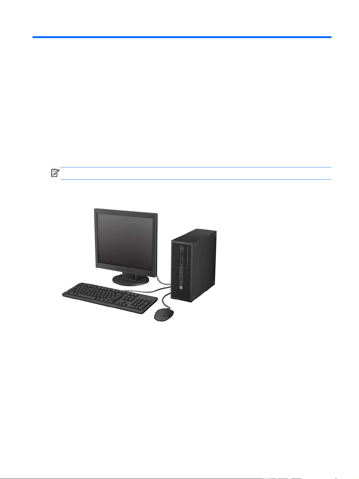
1 Product features
Standard configuration features
Features may vary depending on the model. For a complete listing of the hardware and software
installed in the computer, run the diagnostic utility (included on some computer models only).
NOTE: All three computer models can be used in a tower orientation or a desktop orientation.
Tower (TWR)
Standard configuration features
1
Page 14
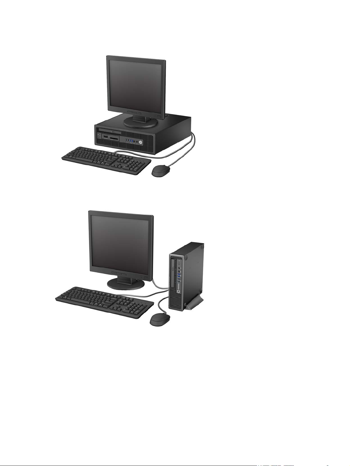
Small Form Factor (SFF)
Ultra-slim Desktop (USDT)
2 Chapter 1 Product features
Page 15
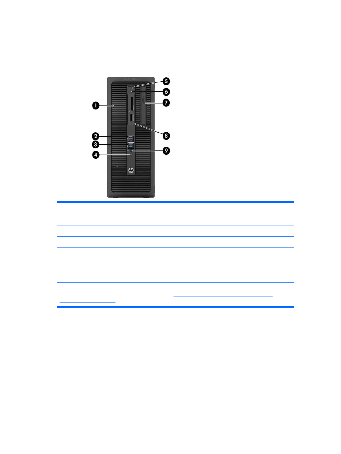
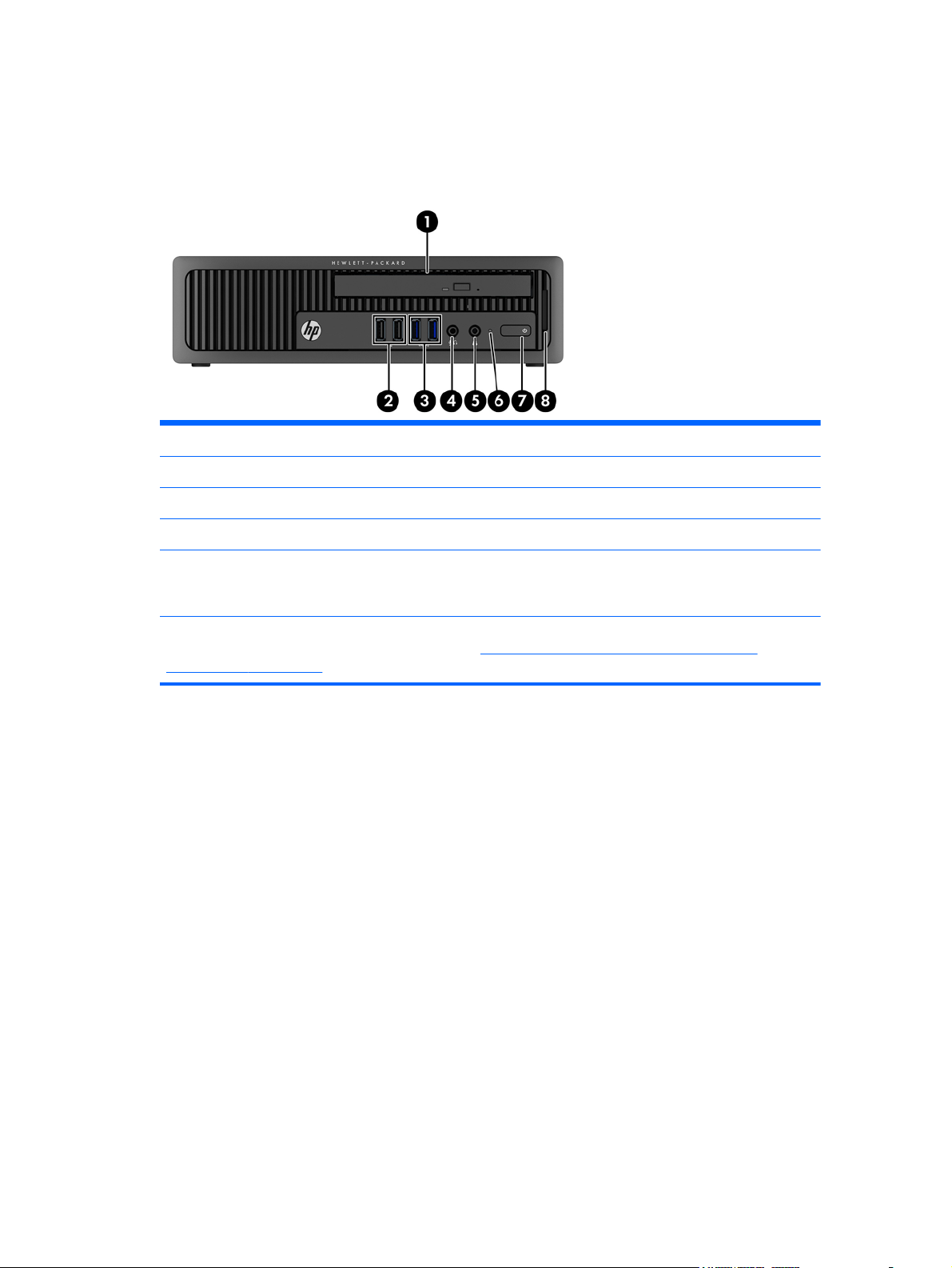
Tower (TWR) front panel components
Drive configuration may vary by model. Some models have a bezel blank covering one or more drive
bays.
1 5.25-inch Half-Height Drive Bay (behind bezel) 6 Hard Drive Activity Light
2 USB 2.0 Ports (black) 7 Slim Optical Drive (optional)
3 USB 3.0 Ports (blue) 8 3.5-inch Media Card Reader (optional)
4 Headphone Connector 9 Microphone/Headphone Connector
5 Dual-State Power Button
NOTE: When a device is plugged into the Microphone/Headphone Connector, a dialog box will pop up asking if
you want to use the connector for a microphone Line-In device or a headphone. You can reconfigure the connector
at any time by double-clicking the Audio Manager icon in the Windows taskbar.
NOTE: The Power On Light is normally white when the power is on. If it is flashing red, there is a problem with the
computer and it is displaying a diagnostic code. Refer to
audible codes on page 246 to interpret the code.
Interpreting POST diagnostic front panel LEDs and
Tower (TWR) front panel components
3
Page 16
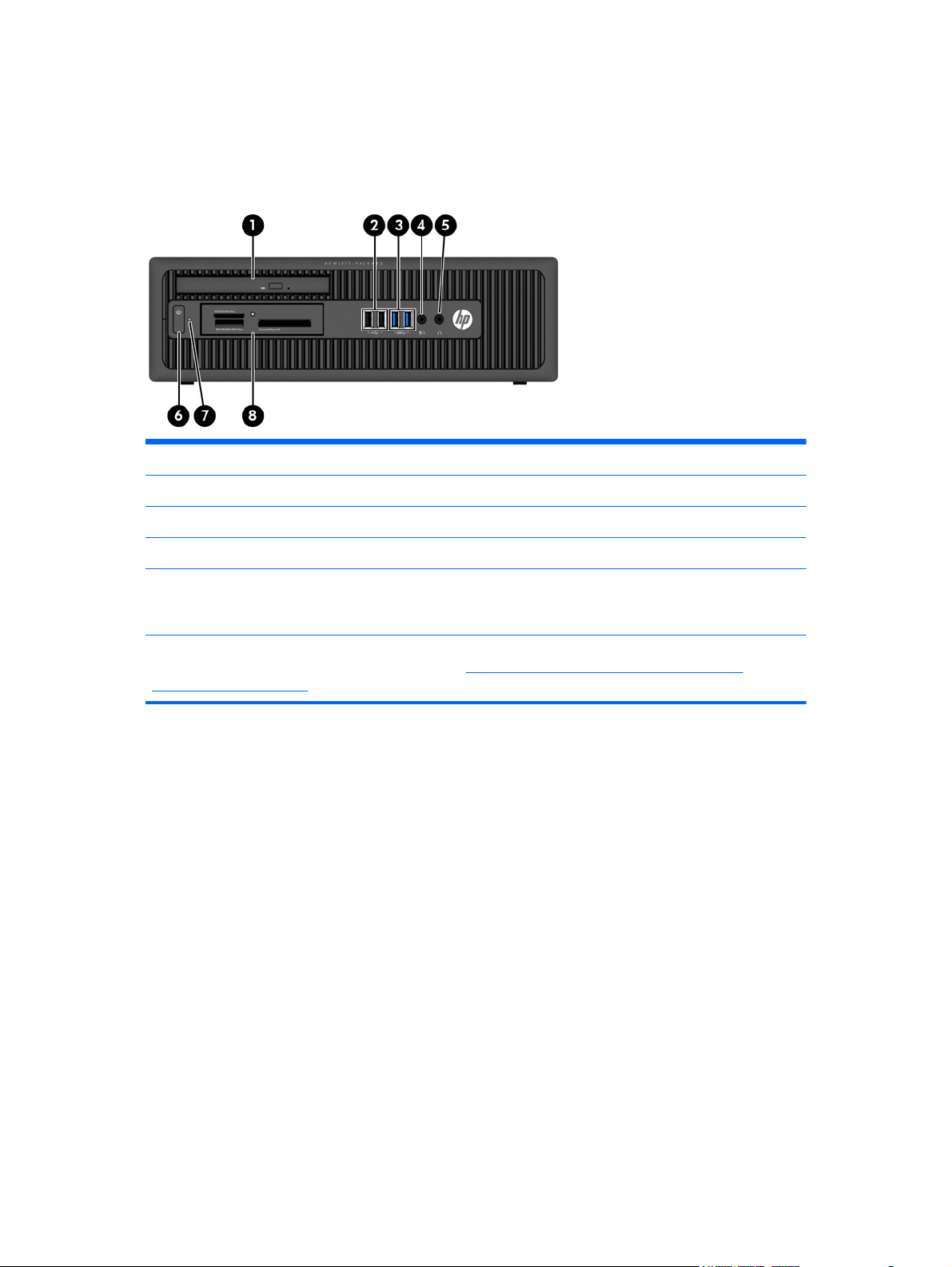
Small Form Factor (SFF) front panel components
Drive configuration may vary by model. Some models have a bezel blank covering one or more drive
bays.
1 Slim Optical Drive (optional) 5 Headphone Connector
2 USB 2.0 Ports (black) 6 Dual-State Power Button
3 USB 3.0 Ports (blue) 7 Hard Drive Activity Light
4 Microphone/Headphone Connector 8 3.5-inch Media Card Reader (optional)
NOTE: When a device is plugged into the Microphone/Headphone Connector, a dialog box will pop up asking if
you want to use the connector for a microphone Line-In device or a headphone. You can reconfigure the connector
at any time by double-clicking the Audio Manager icon in the Windows taskbar.
NOTE: The Power On Light is normally white when the power is on. If it is flashing red, there is a problem with the
computer and it is displaying a diagnostic code.Refer to
audible codes on page 246 to interpret the code.
Interpreting POST diagnostic front panel LEDs and
4 Chapter 1 Product features
Page 17
Ultra-slim Desktop (USDT) front panel components
Drive configuration may vary by model. Some models have a bezel blank covering the optical drive
bay.
1 Slim Optical Drive (optional) 5 Headphone Connector
2 USB 2.0 Ports (black) 6 Hard Drive Activity Light
3 USB 3.0 Ports (blue) 7 Dual-State Power Button
4 Microphone/Headphone Connector 8 SD Media Card Reader (optional)
NOTE: When a device is plugged into the Microphone/Headphone Connector, a dialog box will pop up asking if
you want to use the connector for a microphone Line-In device or a headphone. You can reconfigure the connector
at any time by double-clicking the Audio Manager icon in the Windows taskbar.
NOTE: The Power On Light is normally white when the power is on. If it is flashing red, there is a problem with the
computer and it is displaying a diagnostic code.Refer to
audible codes on page 246 to interpret the code.
Interpreting POST diagnostic front panel LEDs and
Ultra-slim Desktop (USDT) front panel components
5
Page 18
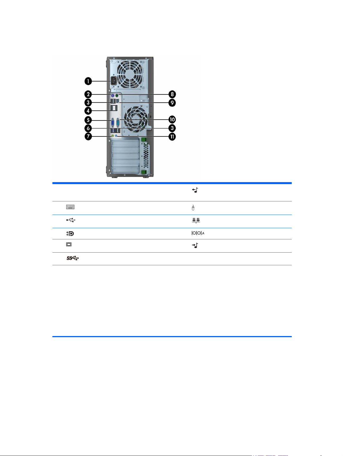
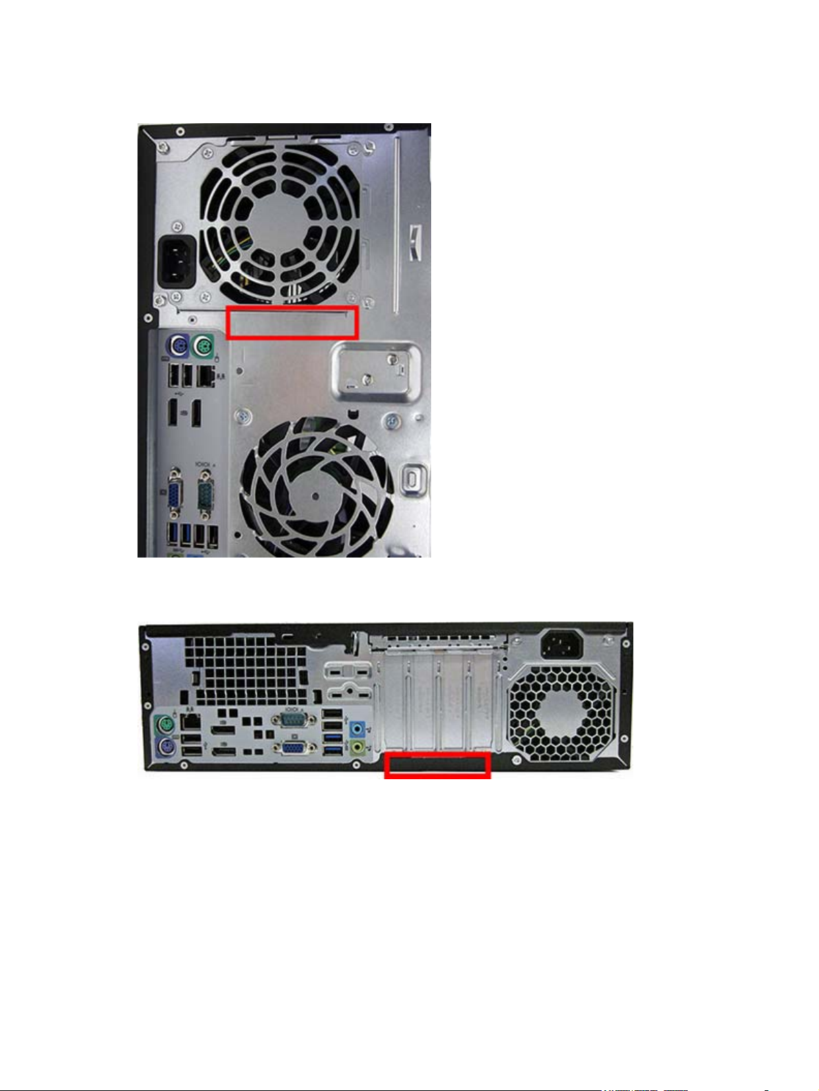
Tower (TWR) rear panel components
1 Power Cord Connector 7 Line-Out Connector for powered audio
devices (green)
2
3
4
5
6
NOTE: An optional second serial port and an optional parallel port are available from HP.
When a device is plugged into the blue Line-In Audio Connector, a dialog box will pop up asking if you want to use
the connector for a line-in device or a microphone. You can reconfigure the connector at any time by double-clicking
the Audio Manager icon in the Windows taskbar.
When a graphics card is installed in one of the system board slots, the video connectors on the graphics card and
the integrated graphics on the system board may be used at the same time. However, for such a configuration, only
the display connected to the discrete graphics card will display POST messages.
The system board graphics can be disabled by changing settings in Computer Setup.
PS/2 Keyboard Connector (purple) 8 PS/2 Mouse Connector (green)
USB 2.0 Ports (black) 9 RJ-45 Network Connector
DisplayPort Monitor Connectors 10 Serial Connector
VGA Monitor Connector 11 Line-In Audio Connector (blue)
USB 3.0 Ports (blue)
6 Chapter 1 Product features
Page 19
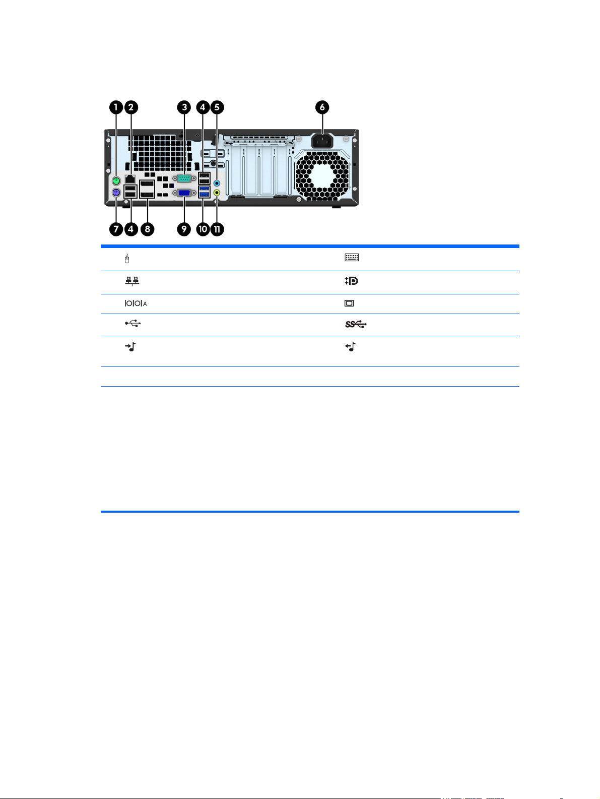
Small Form Factor (SFF) rear panel components
1 PS/2 Mouse Connector (green) 7 PS/2 Keyboard Connector (purple)
2
3
4
5
6 Power Cord Connector
NOTE: An optional second serial port and an optional parallel port are available from HP.
When a device is plugged into the blue Line-In Audio Connector, a dialog box will pop up asking if you want to use
the connector for a line-in device or a microphone. You can reconfigure the connector at any time by double-clicking
the Audio Manager icon in the Windows taskbar.
When a graphics card is installed in one of the system board slots, the video connectors on the graphics card and
the integrated graphics on the system board may be used at the same time. However, for such a configuration, only
the display connected to the discrete graphics card will display POST messages.
The system board graphics can be disabled by changing settings in Computer Setup.
RJ-45 Network Connector 8 DisplayPort Monitor Connectors
Serial Connector 9 VGA Monitor Connector
USB 2.0 Ports (black) 10 USB 3.0 Ports (blue)
Line-In Audio Connector (blue) 11 Line-Out Connector for powered audio
devices (green)
Small Form Factor (SFF) rear panel components
7
Page 20
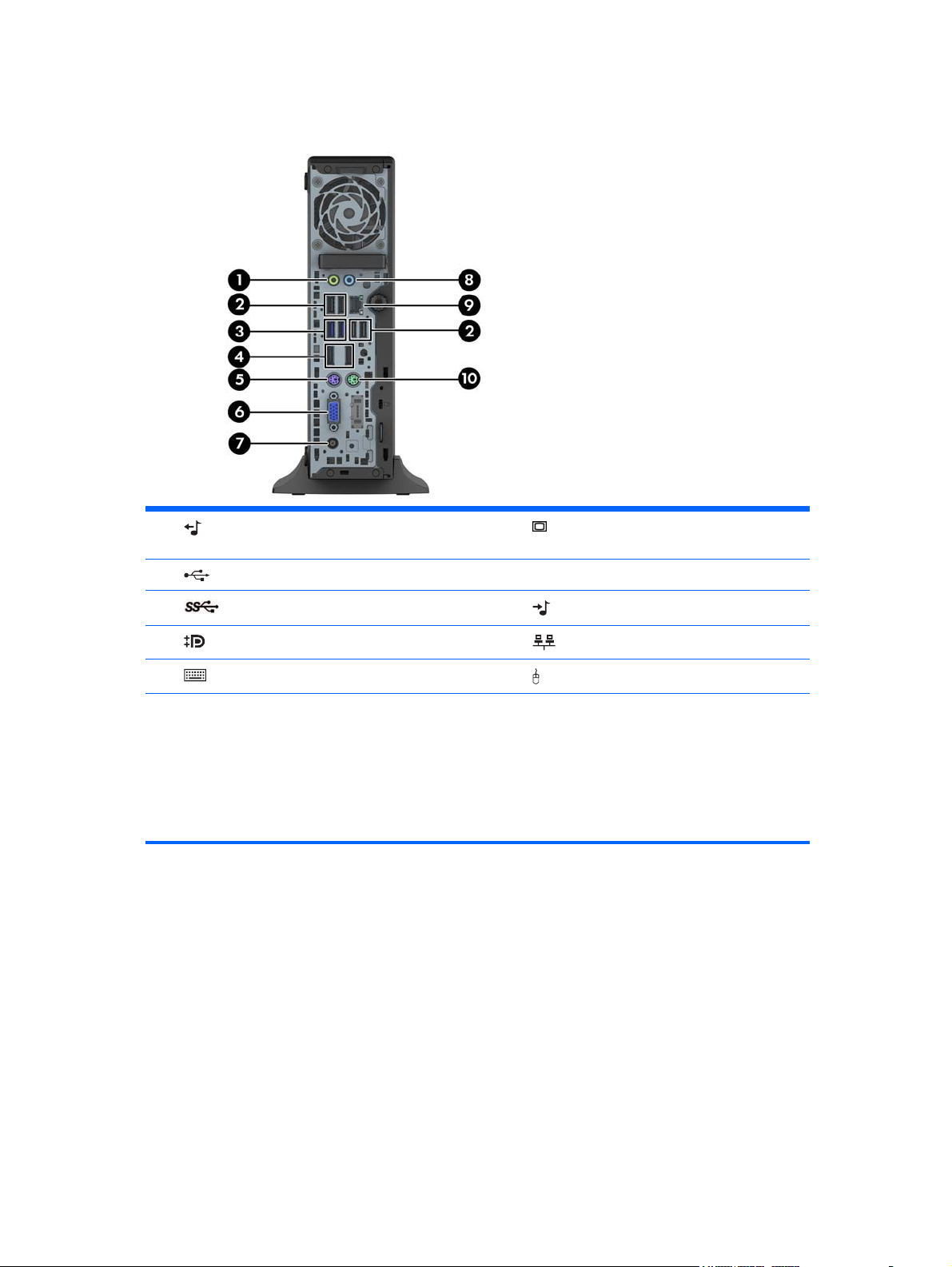
Ultra-slim Desktop (USDT) rear panel components
1 Line-Out Connector for powered audio devices
(green)
2
3
4
5
NOTE: When a device is plugged into the blue Line-In Audio Connector, a dialog box will pop up asking if you
want to use the connector for a line-in device or a microphone. You can reconfigure the connector at any time by
double-clicking the Audio Manager icon in the Windows taskbar.
If an MXM graphics card is installed, all of the video connectors may be used at the same time. However, for such a
configuration, only the display connected to the upper DisplayPort will display POST messages.
The system board graphics can be disabled by changing settings in Computer Setup.
USB 2.0 Ports (black) 7 Power Cord Connector
USB 3.0 Ports (blue) 8 Line-In Audio Connector (blue)
DisplayPort Monitor Connectors 9 RJ-45 Network Connector
PS/2 Keyboard Connector (purple) 10 PS/2 Mouse Connector (green)
Serial number location
Each computer has a unique serial number and a product ID number that are located on the exterior of
the computer. Keep these numbers available for use when contacting customer service for assistance.
6 VGA Monitor Connector
8 Chapter 1 Product features
Page 21
Tower (TWR)
Small Form Factor (SFF)
Serial number location
9
Page 22
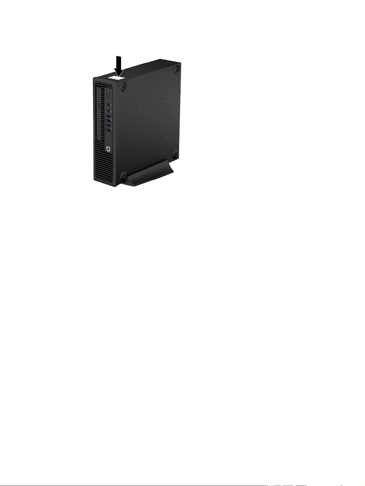
Ultra-slim Desktop (USDT)
10 Chapter 1 Product features
Page 23

2 Activating and Customizing the
Software
NOTE: This chapter provides information for both Windows 7 and Windows 8.
Activating and customizing the software in Windows 7
If your computer was not shipped with a Windows® operating system, some portions of this
documentation do not apply. Additional information is available in online help after you activate the
operating system.
CAUTION: Do not add optional hardware or third-party devices to the computer until the operating
system is successfully activated. Doing so may cause errors and prevent the operating system from
installing properly.
NOTE: Be sure there is a 10.2 cm (4 inch) clearance at the back of the unit and above the monitor to
permit the required airflow.
Activating the Windows operating system
The first time you turn on the computer, the operating system is set up and activated automatically. This
process takes about 5 to 10 minutes. Carefully read and follow the instructions on the screen to
complete the activation.
We recommend that you register your computer with HP during operating system setup so you can
receive important software updates, facilitate support questions, and sign up for special offers.
CAUTION: After the activation process has begun, DO NOT TURN OFF THE COMPUTER UNTIL THE
PROCESS IS COMPLETE. Turning off the computer during the activation process may damage the
software that runs the computer or prevent its proper installation.
NOTE: If the computer shipped with more than one operating system language on the hard drive, the
activation process could take up to 60 minutes.
Activating and customizing the software in Windows 7
11
Page 24

Downloading Windows 7 updates
Microsoft may release updates to the operating system. To help keep the computer running optimally,
HP recommends checking for the latest updates during the initial installation and periodically
throughout the life of the computer.
1. To set up your Internet connection, click Start > Internet Explorer and follow the instructions
on the screen.
2. After an Internet connection has been established, click the Start > All Programs > Windows
Update.
3. Run Windows Update monthly thereafter.
Installing or upgrading device drivers
When installing optional hardware devices after the operating system installation is complete, you must
also install the drivers for each of the devices.
In Windows 7, if prompted for the i386 directory, replace the path specification with C:\i386, or use
the Browse button in the dialog box to locate the i386 folder. This action points the operating system
to the appropriate drivers.
Obtain the latest support software, including support software for the operating system, from
http://www.hp.com/support. Select your country and language, select Download drivers and
software (and firmware), enter the model number of the computer, and press Enter.
Customizing the monitor display
If you wish, you can select or change the monitor refresh rates, screen resolution, color settings, font
sizes, and power management settings.
For more information, refer to the online documentation provided with the graphics controller utility or
the documentation that came with your monitor.
Right-click on the Windows desktop, then click Personalize to change display settings.
Activating and customizing the software in Windows 8
Additional information is available in online help after you activate the operating system.
NOTE: Be sure there is a 10.2 cm (4 inch) clearance at the back of the unit and above the monitor to
permit the required airflow.
Activating the Windows Operating System
The first time you turn on the computer, the operating system is set up and activated automatically. This
process takes about 5 to 10 minutes. Carefully read and follow the instructions on the screen to
complete the activation.
12 Chapter 2 Activating and Customizing the Software
Page 25

We recommend that you register your computer with HP during operating system set up so you can
receive important software updates, facilitate support questions, and sign up for special offers. You can
also register your computer with HP using the Register with HP app on the Start screen.
CAUTION: After the activation process has begun, DO NOT TURN OFF THE COMPUTER UNTIL THE
PROCESS IS COMPLETE. Turning off the computer during the activation process may damage the
software that runs the computer or prevent its proper installation.
Downloading Windows 8 updates
Microsoft may release updates to the operating system. To help keep the computer running optimally,
HP recommends checking for the latest updates during the initial installation and periodically
throughout the life of the computer.
Run Windows Update as soon as possible after you set up your computer.
1. Point to the upper-right or lower-right corner of the Start screen to display the charms.
2. Click Settings > Change PC Settings > Windows Update.
3. Run Windows Update monthly thereafter.
Customizing the monitor display
You can customize display settings for Windows 8 separately for the Start screen and the Desktop.
To customize the Start screen:
1. Point to the upper-right or lower-right corner of the Start screen to display the charms.
2. Click Settings > Change PC Settings.
3. Click Personalize to change the display settings.
To customize the Desktop:
1. Click the Desktop app on the Start screen.
2. Right-click on the desktop, and then click Personalize to change display settings.
Activating and customizing the software in Windows 8
13
Page 26
3 Illustrated parts catalog
This chapter provides spare part information for all chassis.
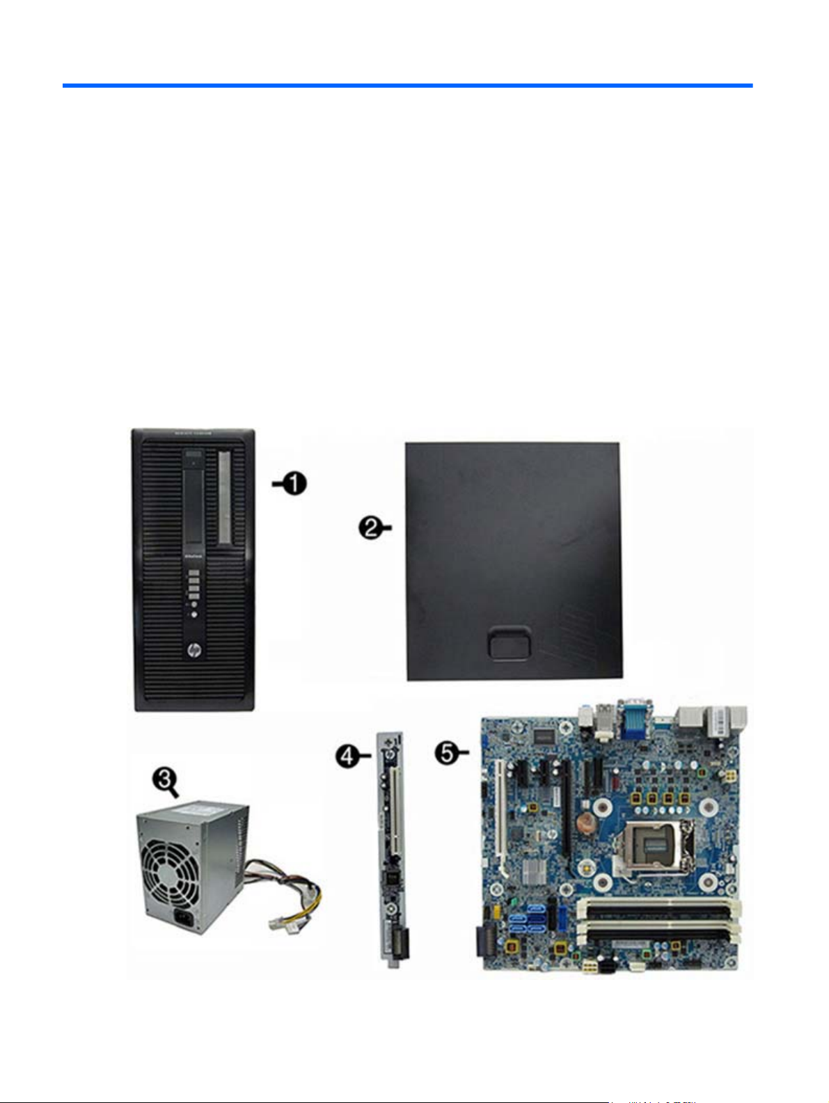
Tower (TWR) chassis spare parts
Computer major components
14 Chapter 3 Illustrated parts catalog
Page 27

Item Description Spare part number
(1) Front bezel
For use in all countries and regions except China 732751-001
For use in China 732752-001
(2) Access panel 732748-001
(3) Power supply
320W, 92% efficient 702452-001
320W, 90% efficient 702453-001
320W, standard 702454-001
320W, HV, standard 707906-001
(4) HP PCI expansion slot daughter card 696971-001
(5) System board (includes replacement thermal material)
For use in models without Windows 8 696969-001
For use in models with Windows 8 Standard 696969-501
For use in models with Windows 8 Professional 696969-601
For use in models with NetClone 727720-001
Memory modules (PC3-12800)
8-GB 689375-001
4-GB 671613-001
2-GB 671612-001
Processors (include replacement thermal material)
Intel Core i7 4770 (3.4-GHz, 8-MB L3 cache) 727373-001
Intel Core i5 4670 (3.4-GHz, 6-MB L3 cache) 727381-001
Intel Core i5 4570 (3.2-GHz, 6-MB L3 cache) 727380-001
Tower (TWR) chassis spare parts
15
Page 28
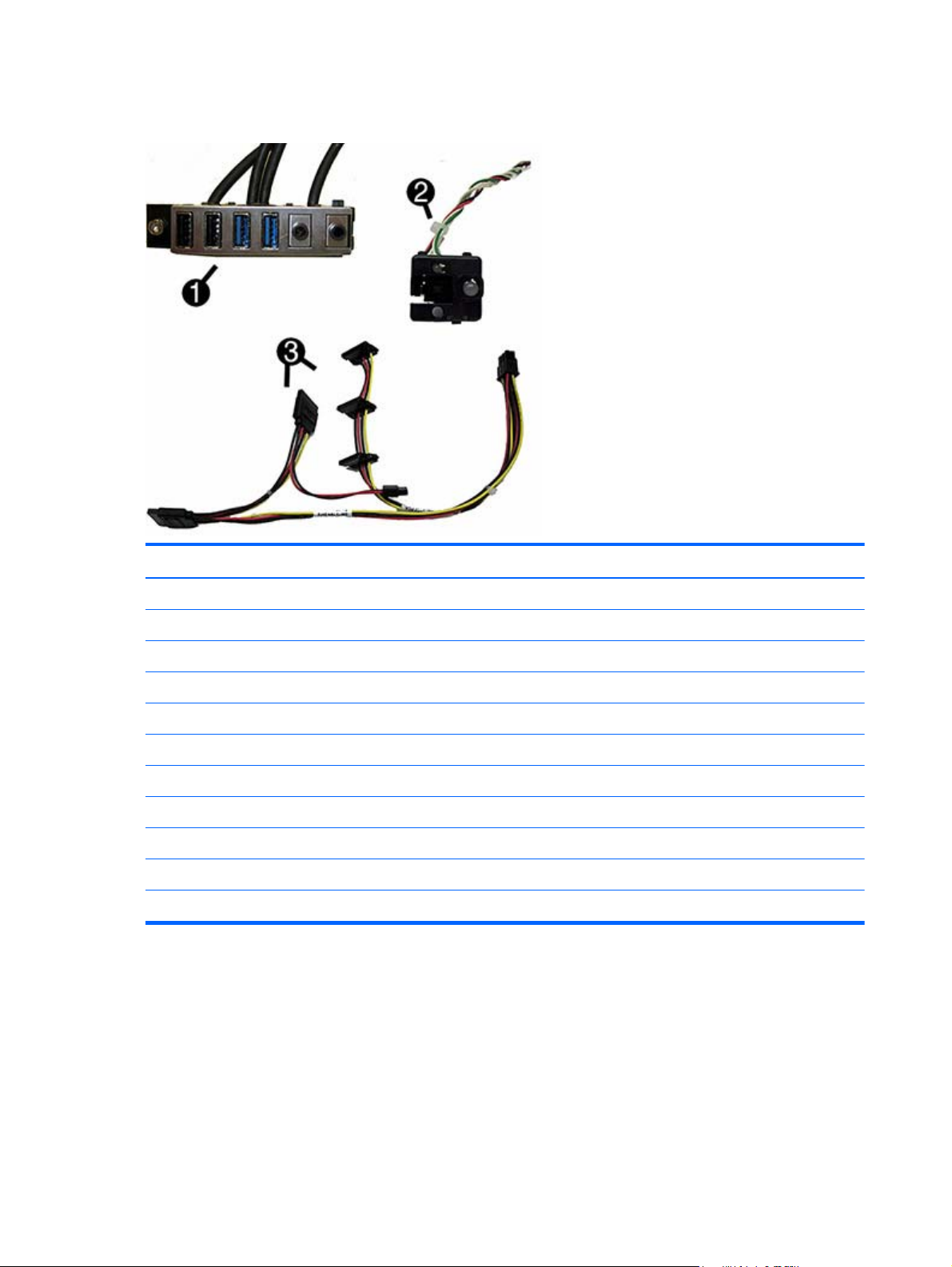
Cables
Item Description Spare part number
(1) Front I/O assembly 732750-001
(2) Power switch/LED assembly 732749-001
(3) Drive power cable 732754-001
Hard drive SATA cable, 14 inch, 1 straight end, 1 angled end 732753-001
Hard drive SATA cable, 17.7 inch, 2 straight ends 639959-001
SATA cable, 18 inch, 1 straight end, 1 angled end 646830-001
DMS-59 to dual VGA cable 463023-001
Adapter, DisplayPort to VGA 632484-001
Adapter, DisplayPort to DVI 662723-001
Adapter, DisplayPort to HDMI 617450-001
DisplayPort cable 487562-001
16 Chapter 3 Illustrated parts catalog
Page 29
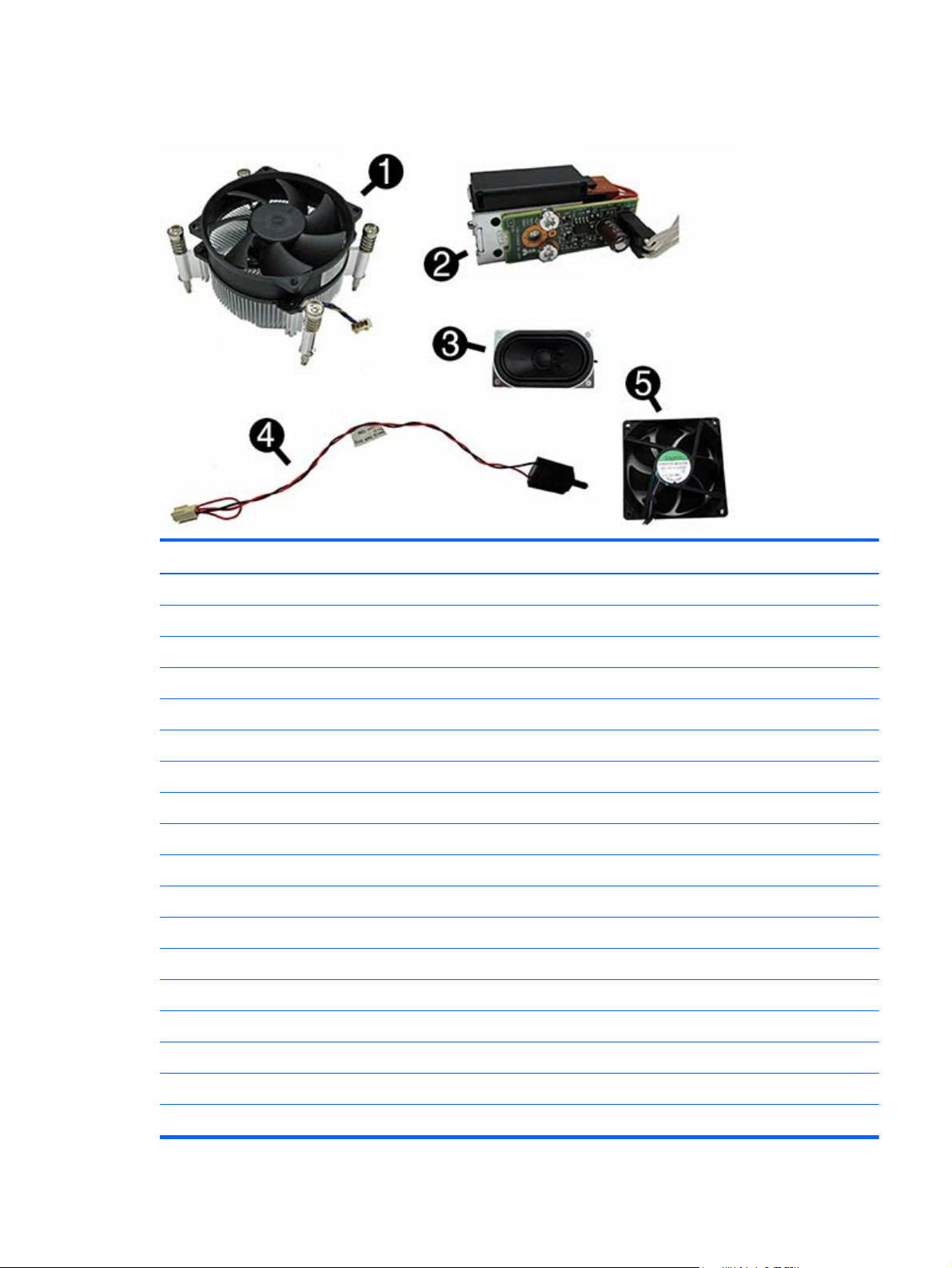
Misc parts
Item Description Spare part number
(1) Fan sink (includes replacement thermal material) 727142-001
(2) Solenoid lock 641498-001
(3) Speaker 645330-001
(4) Hood sensor 638816-001
(5) Fan 727135-001
Optical drive bezel blank 732770-001
Printer port, PCI card 638817-001
HP Ultraslim Keyed Cable Lock 703372-001
Hard drive conversion bracket 397117-001
Serial port, PCI card 638815-001
USB powered speakers 636917-001
Mouse
PS2, optical 674315-001
USB, HP Elite 674318-001
Washable 724795-001
Wireless, HP Elite 674317-001
USB, optical 674316-001
Foot kit 460890-001
Tower (TWR) chassis spare parts
17
Page 30

Drives
Item Description Spare part number
Keyboard
PS/2 724718-xx1
USB 724720-xx1
USB, wireless 724722-xx1
Smart card 701427-xx1
Wireless keyboard, mouse, and dongle 730323-xx1
Description Spare part number
Hard drive
2 TB, 7200 rpm 616608-001
1 TB, hybrid SSD 724937-001
1 TB, 10000 rpm 719106-001
1 TB, 7200 rpm 613202-001
750 GB, 7200 rpm, hybrid SSD 719105-001
500 GB, 10000 rpm 683923-001
500 GB, 7200 rpm, self-encrypting (SED) 696442-001
500 GB, hybrid SSD 724938-001
256 GB Solid-state Drive (SSD), self-encrypting (SED) 680020-001
128 GB Solid-state Drive (SSD) 665961-001
32 GB mSATA drive 686616-001
Optical drive
Blu-ray BD-RW SuperMulti XL Drive 719157-001
DVD±RW drive 657958-001
DVD-ROM drive 608394-001
18 Chapter 3 Illustrated parts catalog
Page 31

Misc boards
Description Spare part number
nVidia Quadro NVS310 PCIe x16 graphics card, 512 MB 707252-001
nVidia Quadro NVS315 PCIe x16 graphics card, 1 GB 720837-001
AMD Radeon HD8490 PCIe x16 graphics card, 1 GB 717219-001
AMD Radeon HD8470 PCIe x16 graphics card, 2 GB DDR3 729085-001
AMD Radeon HD 8350 1GB PCIe x16 DH GFX 717220-001
AMD Radeon HD8350 PCIe x16 graphics card, 1 GB DDR3 729084-001
GeForce GT630 PCIe x16 graphics card, 2 GB 702084-001
Intel PRO/1000 single port GbE NIC, includes bracket 728562-001
HP WLAN 802.11 a/b/g/n 2x2 PCIe module 695915-001
Sequential part number listing
Spare part
number
397117-001 Hard drive conversion bracket
460890-001 Foot kit
463023-001 DMS-59 to dual VGA cable
487562-001 DisplayPort cable
608394-001 DVD-ROM drive
613202-001 1 TB, 7200 rpm hard drive
616608-001 2 TB, 7200 rpm SATA hard drive
617450-001 Adapter, DisplayPort to HDMI
662723-001 Adapter, DisplayPort to DVI
632484-001 Adapter, DisplayPort to VGA
636917-001 USB powered speakers
638815-001 Serial port PCI card
638816-001 Hood sensor
638817-001 Printer port, PCI card
Description
639959-001 Hard drive SATA cable, 17.7 inch, 2 straight ends
641498-001 Solenoid lock
643907-001 Fan sink (includes replacement thermal material)
Tower (TWR) chassis spare parts
19
Page 32

Spare part
number
643908-001 Chassis fan
645330-001 Speaker
646831-001 Hard drive power cable
646832-001 SATA optical drive power cable
657958-001 DVD±RW drive
665961-001 128-GB Solid-state drive
671612-001 Memory module, 2-GB, PC3 12800
671613-001 Memory module, 4-GB, PC3-12800
674315-001 Mouse, PS2, optical
674316-001 Mouse, USB, optical
674317-001 Mouse, wireless
674318-001 Mouse, USB
680020-001 256 GB Solid-state drive, self-encrypting (SED)
683923-001 500 GB, 10000 rpm SATA hard drive
Description
686616-001 32 GB mSATA drive
689375-001 Memory module, 8-GB, PC3-12800
695915-001 HP WLAN 802.11 a/b/g/n 2x2 PCIe NIC
696442-001 500 GB, 7200 rpm hard drive, self-encrypting (SED)
696969-001 System board for use in models without Windows 8 (includes replacement thermal material)
696969-501 System board for use in models with Windows 8 Standard (includes replacement thermal material)
696969-601 System board for use in models with Windows 8 Professional (includes replacement thermal material)
696971-001 HP PCI expansion slot daughter card
701427-xx1 Keyboard, smart card, for use in models with Windows 8
702084-001 GeForce GT630 PCIe x16 graphics card, 2 GB
702452-001 320W, 92% efficient
702453-001 320W, 90% efficient
702454-001 320W, standard
703372-001 HP Ultraslim Keyed Cable Lock
707252-001 nVidia Quadro NVS310 PCIe x16 graphics card, 512 MB
707906-001 320W, HV, standard
717219-001 AMD Radeon HD8490 PCIe x16 graphics card, 1 GB
717220-001 AMD Radeon HD 8350 1GB PCIe x16 DH GFX
20 Chapter 3 Illustrated parts catalog
Page 33

Spare part
number
719105-001 750 GB, 7200 rpm, 2.5-inch hard drive, hybrid SSD
719106-001 1 TB, 10000 rpm hard drive
719157-001 Blu-ray BD-RW SuperMulti XL Drive
720837-001 nVidia Quadro NVS315 PCIe x16 graphics card, 1 GB
724718-xx1 Keyboard, PS/2, for use in models with Windows 8
724720-xx1 Keyboard, USB, black, for use in models with Windows 8
724722-xx1 Keyboard, wireless, for use in models with Windows 8
724795-001 Mouse, washable
724937-001 1 TB hard drive, hybrid SSD
724938-001 500 GB hard drive, hybrid SSD
727135-001 Rear chassis fan
727373-001 Intel Core i7 4770 processor (3.4-GHz, 8-MB L3 cache)
727380-001 Intel Core i5 4570 processor (3.2-GHz, 6-MB L3 cache)
727381-001 Intel Core i5 4670 processor (3.4-GHz, 6-MB L3 cache)
Description
727720-001 System board for use in NetClone models
728562-001 Intel PRO/1000 single port GbE NIC, includes bracket
729084-001 AMD Radeon HD8350 PCIe x16 graphics card, 1 GB DDR3
729085-001 AMD Radeon HD8470 PCIe x16 graphics card, 2 GB DDR3
730323-xx1 Wireless keyboard, mouse, and dongle
732748-001 Access panel
732749-001 Power switch/LED with holder
732750-001 Front I/O assembly
732751-001 Front bezel for use in all countries and regions except for China
732752-001 Front bezel for use in China
732753-001 Hard drive SATA cable, 14 inch, 1 straight end, 1 angled end
732754-001 Drive power cable
732770-001 Optical drive bezel blank
Tower (TWR) chassis spare parts
21
Page 34

Small Form Factor (SFF) chassis spare parts
Computer major components
Item Description Spare part number
(1) Front bezel 732757-001
(2) Access panel 732760-001
(3) Power supply
240W, 92% efficient 702455-001
240W, 90% efficient 702456-001
240W, standard 702457-001
(4) System board (includes replacement thermal material)
For use in models without Windows 8 717522-001
For use in models with Windows 8 Standard 717522-501
For use in models with Windows 8 Professional 717522-601
For use in models with NetClone 727722-001
Memory modules (PC3-12800)
22 Chapter 3 Illustrated parts catalog
Page 35

Cables
Item Description Spare part number
8-GB 689375-001
4-GB 671613-001
2-GB 671612-001
Processors (include replacement thermal material)
Intel Core i7 4770 (3.4-GHz, 8-MB L3 cache) 727373-001
Intel Core i5 4670 (3.4-GHz, 6-MB L3 cache) 727381-001
Intel Core i5 4570 (3.2-GHz, 6-MB L3 cache) 727380-001
Item Description Spare part number
(1) Front I/O assembly 732755-001
(2) Power switch assembly 732756-001
(3) SATA drive power cable 732759-001
Hard drive SATA cable, 14 inch, 1 straight end, 1 angled end 732753-001
Optical drive SATA cable, 19.5 inch, 2 straight ends 638813-001
SATA cable, 25.2 inch, 1 straight end, 1 angled end 638814-001
DMS-59 to dual VGA cable 463023-001
Adapter, DisplayPort to VGA 632484-001
Adapter, DisplayPort to DVI 662723-001
Adapter, DisplayPort to HDMI 617450-001
DisplayPort cable 487562-001
Small Form Factor (SFF) chassis spare parts
23
Page 36

Misc parts
Item Description Spare part number
(1) Fan sink (includes replacement thermal material) 727150-001
(2) Fan duct 727145-001
(3) Speaker 727149-001
(4) Hood sensor 638816-001
Optical drive bezel blank 732769-001
Solenoid lock 732772-001
Printer port, PCI card 638817-001
HP Ultraslim Keyed Cable Lock 703372-001
Rubber foot 583654-001
Chassis stand 688952-001
Serial port, PCI card 638815-001
Hard drive conversion bracket 397117-001
USB powered speakers 636917-001
Mouse
PS2, optical 674315-001
USB, HP Elite 674318-001
Washable 724795-001
Wireless, HP Elite 674317-001
USB, optical 674316-001
Foot kit 583654-001
24 Chapter 3 Illustrated parts catalog
Page 37

Drives
Item Description Spare part number
Keyboard
PS/2 724718-xx1
USB 724720-xx1
USB, wireless 724722-xx1
Smart card 701427-xx1
Wireless keyboard, mouse, and dongle 730323-xx1
Description Spare part number
Hard drive
2 TB, 7200 rpm 616608-001
1 TB hard drive, hybrid SSD 724937-001
1 TB, 10000 rpm 719106-001
1 TB, 7200 rpm 613202-001
750 GB, 7200 rpm, hybrid SSD 719105-001
500 GB, 10000 rpm 683923-001
500 GB, 7200 rpm, self-encrypting (SED) 696442-001
500 GB hard drive, hybrid SSD 724938-001
256-GB Solid-state Drive (SSD), self-encrypting (SED) 680020-001
128-GB Solid-state Drive (SSD) 665961-001
32 GB mSATA drive 686616-001
Optical drive
Blu-ray BD-RW SuperMulti XL Drive 719157-001
DVD±RW drive 657958-001
DVD-ROM drive 608394-001
NOTE: 2.5-inch solid-state drives require an adapter for installation.
Misc boards
Description Spare part number
nVidia Quadro NVS310 PCIe x16 graphics card, 512 MB 707252-001
Small Form Factor (SFF) chassis spare parts
25
Page 38

Description Spare part number
nVidia Quadro NVS315 PCIe x16 graphics card, 1 GB 720837-001
AMD Radeon HD8490 PCIe x16 graphics card, 1 GB 717219-001
AMD Radeon HD8450 PCIe x16 graphics card, 1 GB 717220-001
GeForce GT630 PCIe x16 graphics card, 2 GB 702084-001
Intel PRO/1000 single port GbE NIC, includes bracket 728562-001
HP WLAN 802.11 a/b/g/n 2x2 PCIe module 695915-001
Sequential part number listing
Spare part
number
397117-001 Hard drive conversion bracket
463023-001 DMS-59 to dual VGA cable
487562-001 DisplayPort cable
583654-001 Rubber foot
608394-001 DVD-ROM drive
613202-001 1 TB, 7200 rpm hard drive
616608-001 2 TB, 7200 rpm SATA hard drive
617450-001 Adapter, DisplayPort to HDMI
632484-001 Adapter, DisplayPort to VGA
636917-001 USB powered speakers
638813-001 Optical drive SATA cable, 19.5 inch, 2 straight ends
638814-001 SATA cable, 25.2 inch, 1 straight end, 1 angled end
638815-001 Serial port PCI card
638816-001 Hood sensor
Description
638817-001 Printer port, PCI card
657958-001 DVD±RW drive
662723-001 Adapter, DisplayPort to DVI
665961-001 128-GB Solid-state drive
671612-001 Memory module, 2-GB, PC3 12800
671613-001 Memory module, 4-GB, PC3-12800
674317-001 Mouse, wireless, HP Elite
674318-001 Mouse, USB, HP Elite
26 Chapter 3 Illustrated parts catalog
Page 39

Spare part
number
674315-001 Mouse, PS2, optical
674316-001 Mouse, USB, optical
680020-001 256-GB Solid-state drive, self-encrypting (SED)
683923-001 500 GB, 10000 rpm SATA hard drive
686616-001 32 GB mSATA drive
688952-001 Chassis stand
689375-001 Memory module, 8-GB, PC3-12800
695915-001 HP WLAN 802.11 a/b/g/n 2x2 PCIe NIC
696442-001 500 GB, 7200 rpm hard drive, self-encrypting (SED)
701427-xx1 Keyboard, smart card, for use in models with Windows 8
702455-001 320W, 92% efficient
702456-001 320W, 90% efficient
702457-001 320W, standard
703372-001 HP Ultraslim Keyed Cable Lock
Description
707252-001 nVidia Quadro NVS310 PCIe x16 graphics card, 512 MB
717219-001 AMD Radeon HD8490 PCIe x16 graphics card, 1 GB
717220-001 AMD Radeon HD8450 PCIe x16 graphics card, 1 GB
717522-001 System board for use in models without Windows 8 (includes replacement thermal material)
717522-501 System board for use in models with Windows 8 Standard (includes replacement thermal material)
717522-601 System board for use in models with Windows 8 Professional (includes replacement thermal material)
719105-001 750 GB, 7200 rpm, 2.5-inch, hard drive, hybrid SSD
719106-001 1 TB, 10000 rpm hard drive
719157-001 Blu-ray BD-RW SuperMulti XL Drive
720837-001 nVidia Quadro NVS315 PCIe x16 graphics card, 1 GB
724718-xx1 Keyboard, PS/2, for use in models with Windows 8
724720-xx1 Keyboard, USB, black, for use in models with Windows 8
724722-xx1 Keyboard, wireless, for use in models with Windows 8
724795-001 Mouse, washable
724937-001 1 TB hard drive, hybrid SSD
724938-001 500 GB hard drive, hybrid SSD
727145-001 Fan duct
727149-001 Speaker
Small Form Factor (SFF) chassis spare parts
27
Page 40

Spare part
number
727150-001 Fan sink
727373-001 Intel Core i7 4770 processor (3.4-GHz, 8-MB L3 cache)
727380-001 Intel Core i5 4570 processor (3.2-GHz, 6-MB L3 cache)
727381-001 Intel Core i5 4670 processor (3.4-GHz, 6-MB L3 cache)
727722-001 System board for use in NetClone models (includes replacement thermal material)
728562-001 Intel PRO/1000 single port GbE NIC, includes bracket
732753-001 Hard drive SATA cable, 14 inch, 1 straight end, 1 angled end
732759-001 SATA drive power cable
732755-001 Front I/O cable assembly
732756-001 Power switch assembly
732757-001 Front bezel
732760-001 Access panel
732769-001 Optical drive bezel blank
732772-001 Solenoid lock
Description
28 Chapter 3 Illustrated parts catalog
Page 41

Ultra-Slim Desktop (USDT) chassis spare parts
Computer major components
Item Description Spare part number
(1) Access panel 732763-001
(2) Front bezel 732764-001
(3) Stand 612496-001
(4) System board (includes replacement thermal material)
For use in models without Windows 8 696970-001
For use in models with Windows 8 Standard 696970-501
For use in models with Windows 8 Professional 696970-601
For use in models with NetClone 727721-001
AC adapter
180W, standard 613766-001
135W, standard 648964-001
Memory modules (PC3-12800)
8-GB 689374-001
4-GB 689373-001
Ultra-Slim Desktop (USDT) chassis spare parts
29
Page 42

Cables
Item Description Spare part number
2-GB 689372-001
Processors (include replacement thermal material
Intel Core i7 4770s (3.1-GHz, 8-MB L3 cache) 732507-001
Intel Core i5 4670s (3.1-GHz, 6-MB L3 cache) 732506-001
Intel Core i5 4570s (2.9-GHz, 6-MB L3 cache) 732505-001
Item Description Spare part number
(1) Optical drive cable/connector 605163-001
Adapter, DisplayPort to VGA 632484-001
Adapter, DisplayPort to DVI 662723-001
Adapter, DisplayPort to HDMI 617450-001
DisplayPort cable 487562-001
30 Chapter 3 Illustrated parts catalog
Page 43

Misc parts
Item Description Spare part number
(1) Heat sink for use with the processor (includes replacement thermal material) 587456-001
Heat sink for use with the discrete graphics card (includes replacement thermal
material; not illustrated)
(2) Power switch assembly 732767-001
(3) Speaker 689384-001
(4) Rear port cover 588981-001
(5) Fan, rear 732766-001
(6) Front I/O panel 732762-001
(7) Chassis fan, front 732765-001
Optical drive bezel blank 732771-001
Solenoid lock 732772-001
HP Ultraslim Keyed Cable Lock 703372-001
Drive cage 732761-001
USB powered speakers 636917-001
Mouse
689369-001
Ultra-Slim Desktop (USDT) chassis spare parts
31
Page 44

Drives
Item Description Spare part number
PS2, optical 674315-001
USB, HP Elite 674318-001
Washable 724795-001
Wireless, HP Elite 674317-001
USB, optical 674316-001
Keyboard
PS/2 724718-xx1
USB, basic 724720-xx1
USB, wireless 724722-xx1
Smart card 701427-xx1
Wireless keyboard, dongle, and mouse 730323-xx1
Description Spare part number
Hard drive
750 GB, 7200 rpm, hybrid SSD 719105-001
500 GB, 7200 rpm, self-encrypting (SED) 696442-001
500 GB, 7200 rpm 686217-001
320 GB, 7200 rpm 639135-001
500 GB hard drive, hybrid SSD 724938-001
256-GB Solid-state Drive (SSD), self-encrypting (SED) 680020-001
128-GB Solid-state Drive (SSD) 665961-001
32-GB Solid-state Drive (SSD) 686616-001
32-GB mSATA drive 719566-001
Optical drive
DVD-ROM drive 608394-001
DVD±RW drive 657958-001
Blu-ray BD-RW SuperMulti XL Drive 719157-001
32 Chapter 3 Illustrated parts catalog
Page 45

Misc boards
Description Spare part number
AMD Radeon HD 7650A 2GB MXM Graphics 708866-001
HP WLAN 802.11 a/b/g/n 2x2 PCIe NIC 695915-001
Sequential part number listing
Spare part
number
487562-001 DisplayPort cable
587456-001 Heat sink for use with the processor (includes thermal material)
605163-001 Optical drive cable/connector
608394-001 DVD-ROM drive
612496-001 Stand
613766-001 180-W power adapter, standard
617450-001 Adapter, DisplayPort to HDMI
632484-001 Adapter, DisplayPort to VGA
636917-001 USB powered speakers
638816-001 Hood sensor
639135-001 320 GB, 7200 rpm hard drive
648964-001 AC adapter, 135W, standard
657958-001 DVD±RW drive
662723-001 Adapter, DisplayPort to DVI
Description
665961-001 128-GB Solid-state drive
674315-001 Mouse, PS2, optical
674316-001 Mouse, USB, optical
674317-001 Mouse, wireless, HP Elite
674318-001 Mouse, USB, HP Elite
680020-001 256-GB Solid-state drive, self-encrypting (SED)
686217-001 500 GB, 7200 rpm hard drive
686616-001 32-GB Solid-state drive
689369-001 Heat sink for use on models with discrete graphics cards (includes thermal material)
689372-001 Memory module, 2-GB, PC3-12800
Ultra-Slim Desktop (USDT) chassis spare parts
33
Page 46

Spare part
number
689373-001 Memory module, 4-GB, PC3-12800
689374-001 Memory module, 8-GB, PC3-12800
689384-001 Speaker
695915-001 HP WLAN 802.11 a/b/g/n 2x2 PCIe NIC
696442-001 500 GB, 7200 rpm, self-encrypting (SED) hard drive
696970-001 System board (includes replacement thermal material)
701427-xx1 Keyboard, smart card, for use in models with Windows 8
703372-001 HP Ultraslim Keyed Cable Lock
708866-001 AMD Radeon HD 7650A 2GB MXM Graphics
719105-001 750 GB, 7200 rpm hard drive, hybrid SSD
719157-001 Blu-ray BD-RW SuperMulti XL Drive
719566-001 32-GB mSATA drive
724718-xx1 Keyboard, PS/2, for use in models with Windows 8
724720-xx1 Keyboard, USB, black, for use in models with Windows 8
Description
724722-xx1 Keyboard, wireless, for use in models with Windows 8
724795-001 Mouse, washable
724938-001 500 GB hard drive, hybrid SSD
727721-001 System board for use in NetClone models
732505-001 Intel Core i5 4570s processor (2.9-GHz, 6-MB L3 cache)
732506-001 Intel Core i5 4670s processor (3.1-GHz, 6-MB L3 cache)
732507-001 Intel Core i7 4770s processor (3.1-GHz, 8-MB L3 cache)
732761-001 Drive cage
732762-001 Front I/O assembly
732763-001 Access panel
732764-001 Front bezel
732765-001 Front fan
732766-001 Chassis fan, rear
732767-001 Power switch assembly
732771-001 Optical drive bezel blank
732772-001 Solenoid lock
34 Chapter 3 Illustrated parts catalog
Page 47

4 Routine care, SATA drive
guidelines, and disassembly
preparation
This chapter provides general service information for the computer. Adherence to the procedures and
precautions described in this chapter is essential for proper service.
CAUTION: When the computer is plugged into an AC power source, voltage is always applied to
the system board. You must disconnect the power cord from the power source before opening the
computer to prevent system board or component damage.
Electrostatic discharge information
A sudden discharge of static electricity from your finger or other conductor can destroy static-sensitive
devices or microcircuitry. Often the spark is neither felt nor heard, but damage occurs. An electronic
device exposed to electrostatic discharge (ESD) may not appear to be affected at all and can work
perfectly throughout a normal cycle. The device may function normally for a while, but it has been
degraded in the internal layers, reducing its life expectancy.
Networks built into many integrated circuits provide some protection, but in many cases, the discharge
contains enough power to alter device parameters or melt silicon junctions.
Electrostatic discharge information
35
Page 48

Generating static
The following table shows that:
Different activities generate different amounts of static electricity.
●
Static electricity increases as humidity decreases.
●
Relative Humidity
Event 55% 40% 10%
Walking across carpet
Walking across vinyl floor
Motions of bench worker
Removing DIPs from plastic tube
Removing DIPs from vinyl tray
Removing DIPs from Styrofoam
Removing bubble pack from PCB
Packing PCBs in foam-lined box
These are then multi-packaged inside plastic tubes, trays, or Styrofoam.
7,500 V
3,000 V
400 V
400 V
2,000 V
3,500 V
7,000 V
5,000 V
NOTE: 700 volts can degrade a product.
Preventing electrostatic damage to equipment
Many electronic components are sensitive to ESD. Circuitry design and structure determine the degree
of sensitivity. The following packaging and grounding precautions are necessary to prevent damage to
electric components and accessories.
15,000 V
5,000 V
800 V
700 V
4,000 V
5,000 V
20,000 V
11,000 V
35,000 V
12,000 V
6,000 V
2,000 V
11,500 V
14,500 V
26,500 V
21,000 V
To avoid hand contact, transport products in static-safe containers such as tubes, bags, or boxes.
●
Protect all electrostatic parts and assemblies with conductive or approved containers or
●
packaging.
Keep electrostatic sensitive parts in their containers until they arrive at static-free stations.
●
Place items on a grounded surface before removing them from their container.
●
Always be properly grounded when touching a sensitive component or assembly.
●
Avoid contact with pins, leads, or circuitry.
●
Place reusable electrostatic-sensitive parts from assemblies in protective packaging or conductive
●
foam.
36 Chapter 4 Routine care, SATA drive guidelines, and disassembly preparation
Page 49

Personal grounding methods and equipment
Use the following equipment to prevent static electricity damage to equipment:
Wrist straps are flexible straps with a maximum of one-megohm ± 10% resistance in the ground
●
cords. To provide proper ground, a strap must be worn snug against bare skin. The ground cord
must be connected and fit snugly into the banana plug connector on the grounding mat or
workstation.
Heel straps/Toe straps/Boot straps can be used at standing workstations and are
●
compatible with most types of shoes or boots. On conductive floors or dissipative floor mats, use
them on both feet with a maximum of one-megohm ± 10% resistance between the operator and
ground.
Static Shielding Protection Levels
Method Voltage
Antistatic plastic
Carbon-loaded plastic
Metallized laminate
Grounding the work area
To prevent static damage at the work area, use the following precautions:
Cover the work surface with approved static-dissipative material. Provide a wrist strap connected
●
to the work surface and properly grounded tools and equipment.
Use static-dissipative mats, foot straps, or air ionizers to give added protection.
●
Handle electrostatic sensitive components, parts, and assemblies by the case or PCB laminate.
●
Handle them only at static-free work areas.
Turn off power and input signals before inserting and removing connectors or test equipment.
●
Use fixtures made of static-safe materials when fixtures must directly contact dissipative surfaces.
●
Keep work area free of nonconductive materials such as ordinary plastic assembly aids and
●
Styrofoam.
1,500
7,500
15,000
Use field service tools, such as cutters, screwdrivers, and vacuums, that are conductive.
●
Recommended materials and equipment
Materials and equipment that are recommended for use in preventing static electricity include:
Antistatic tape
●
Antistatic smocks, aprons, or sleeve protectors
●
Conductive bins and other assembly or soldering aids
●
Electrostatic discharge information
37
Page 50

Conductive foam
●
Conductive tabletop workstations with ground cord of one-megohm +/- 10% resistance
●
Static-dissipative table or floor mats with hard tie to ground
●
Field service kits
●
Static awareness labels
●
Wrist straps and footwear straps providing one-megohm +/- 10% resistance
●
Material handling packages
●
Conductive plastic bags
●
Conductive plastic tubes
●
Conductive tote boxes
●
Opaque shielding bags
●
Transparent metallized shielding bags
●
Transparent shielding tubes
●
Operating guidelines
To prevent overheating and to help prolong the life of the computer:
Keep the computer away from excessive moisture, direct sunlight, and extremes of heat and cold.
●
Operate the computer on a sturdy, level surface. Leave a 10.2-cm (4-inch) clearance on all vented
●
sides of the computer and above the monitor to permit the required airflow.
Never restrict the airflow into the computer by blocking any vents or air intakes. Do not place the
●
keyboard, with the keyboard feet down, directly against the front of the desktop unit as this also
restricts airflow.
Occasionally clean the air vents on all vented sides of the computer. Lint, dust, and other foreign
●
matter can block the vents and limit the airflow. Be sure to unplug the computer before cleaning
the air vents.
Never operate the computer with the cover or side panel removed.
●
Do not stack computers on top of each other or place computers so near each other that they are
●
subject to each other’s re-circulated or preheated air.
If the computer is to be operated within a separate enclosure, intake and exhaust ventilation must
●
be provided on the enclosure, and the same operating guidelines listed above will still apply.
Keep liquids away from the computer and keyboard.
●
38 Chapter 4 Routine care, SATA drive guidelines, and disassembly preparation
Page 51

Never cover the ventilation slots on the monitor with any type of material.
●
Install or enable power management functions of the operating system or other software, including
●
sleep states.
Routine care
General cleaning safety precautions
1. Never use solvents or flammable solutions to clean the computer.
2. Never immerse any parts in water or cleaning solutions; apply any liquids to a clean cloth and
then use the cloth on the component.
3. Always unplug the computer when cleaning with liquids or damp cloths.
4. Always unplug the computer before cleaning the keyboard, mouse, or air vents.
5. Disconnect the keyboard before cleaning it.
6. Wear safety glasses equipped with side shields when cleaning the keyboard.
Cleaning the Computer Case
Follow all safety precautions in General cleaning safety precautions on page 39 before cleaning the
computer.
To clean the computer case, follow the procedures described below:
To remove light stains or dirt, use plain water with a clean, lint-free cloth or swab.
●
For stronger stains, use a mild dishwashing liquid diluted with water. Rinse well by wiping it with
●
a cloth or swab dampened with clear water.
For stubborn stains, use isopropyl (rubbing) alcohol. No rinsing is needed as the alcohol will
●
evaporate quickly and not leave a residue.
After cleaning, always wipe the unit with a clean, lint-free cloth.
●
Occasionally clean the air vents on the computer. Lint and other foreign matter can block the vents
●
and limit the airflow.
Cleaning the keyboard
Follow all safety precautions in General cleaning safety precautions on page 39 before cleaning the
keyboard.
To clean the tops of the keys or the keyboard body, follow the procedures described in
Computer Case on page 39.
When cleaning debris from under the keys, review all rules in
on page 39 before following these procedures:
General cleaning safety precautions
Routine care
Cleaning the
39
Page 52

CAUTION: Use safety glasses equipped with side shields before attempting to clean debris from
under the keys.
Visible debris underneath or between the keys may be removed by vacuuming or shaking.
●
Canned, pressurized air may be used to clean debris from under the keys. Caution should be used
●
as too much air pressure can dislodge lubricants applied under the wide keys.
If you remove a key, use a specially designed key puller to prevent damage to the keys. This tool
●
is available through many electronic supply outlets.
CAUTION: Never remove a wide leveled key (like the space bar) from the keyboard. If these
keys are improperly removed or installed, the keyboard may not function properly.
Cleaning under a key may be done with a swab moistened with isopropyl alcohol and squeezed
●
out. Be careful not to wipe away lubricants necessary for proper key functions. Use tweezers to
remove any fibers or dirt in confined areas. Allow the parts to air dry before reassembly.
Cleaning the monitor
Wipe the monitor screen with a clean cloth moistened with water or with a towelette designed for
●
cleaning monitors. Do not use sprays or aerosols directly on the screen; the liquid may seep into
the housing and damage a component. Never use solvents or flammable liquids on the monitor.
To clean the monitor body follow the procedures in
●
Cleaning the mouse
Before cleaning the mouse, ensure that the power to the computer is turned off.
Clean the mouse ball by first removing the retaining plate and the ball from the housing. Pull out
●
any debris from the ball socket and wipe the ball with a clean, dry cloth before reassembly.
To clean the mouse body, follow the procedures in
●
Service considerations
Listed below are some of the considerations that you should keep in mind during the disassembly and
assembly of the computer.
Power supply fan
The power supply fan is a variable-speed fan based on the temperature in the power supply.
CAUTION: The cooling fan is always on when the computer is in the “On” mode. The cooling fan is
off when the computer is in “Standby,” “Suspend,” or “Off” modes.
Cleaning the Computer Case on page 39.
Cleaning the Computer Case on page 39.
You must disconnect the power cord from the power source before opening the computer to prevent
system board or component damage.
40 Chapter 4 Routine care, SATA drive guidelines, and disassembly preparation
Page 53

Tools and software Requirements
To service the computer, you need the following:
Torx T-15 screwdriver
●
Torx T-15 screwdriver with small diameter shank (for certain front bezel removal)
●
Flat-bladed screwdriver (may sometimes be used in place of the Torx screwdriver)
●
Phillips #2 screwdriver
●
Diagnostics software
●
Tamper-resistant T-15 wrench
●
Screws
The screws used in the computer are not interchangeable. They may have standard or metric threads
and may be of different lengths. If an incorrect screw is used during the reassembly process, it can
damage the unit. HP strongly recommends that all screws removed during disassembly be kept with the
part that was removed, then returned to their proper locations.
CAUTION: Metric screws have a black finish. U.S. screws have a silver finish and are used on hard
drives only.
CAUTION: As each subassembly is removed from the computer, it should be placed away from the
work area to prevent damage.
Cables and connectors
Most cables used throughout the unit are flat, flexible cables. These cables must be handled with care
to avoid damage. Apply only the tension required to seat or unseat the cables during insertion or
removal from the connector. Handle cables by the connector whenever possible. In all cases, avoid
bending or twisting the cables, and ensure that the cables are routed in such a way that they cannot be
caught or snagged by parts being removed or replaced.
CAUTION: When servicing this computer, ensure that cables are placed in their proper location
during the reassembly process. Improper cable placement can damage the computer.
Hard Drives
Handle hard drives as delicate, precision components, avoiding all physical shock and vibration. This
applies to failed drives as well as replacement spares.
If a drive must be mailed, place the drive in a bubble-pack mailer or other suitable protective
●
packaging and label the package “Fragile: Handle With Care.”
Do not remove hard drives from the shipping package for storage. Keep hard drives in their
●
protective packaging until they are actually mounted in the CPU.
Avoid dropping drives from any height onto any surface.
●
Service considerations
41
Page 54

If you are inserting or removing a hard drive, turn off the computer. Do not remove a hard drive
●
while the computer is on or in standby mode.
Before handling a drive, ensure that you are discharged of static electricity. While handling a
●
drive, avoid touching the connector. For more information about preventing electrostatic damage,
refer to
Do not use excessive force when inserting a drive.
●
Avoid exposing a hard drive to liquids, temperature extremes, or products that have magnetic
●
Electrostatic discharge information on page 35
fields such as monitors or speakers.
Lithium coin cell battery
The battery that comes with the computer provides power to the real-time clock and has a minimum
lifetime of about three years.
See the appropriate removal and replacement chapter for the chassis you are working on in this guide
for instructions on the replacement procedures.
WARNING! This computer contains a lithium battery. There is a risk of fire and chemical burn if the
battery is handled improperly. Do not disassemble, crush, puncture, short external contacts, dispose in
water or fire, or expose it to temperatures higher than 140ºF (60ºC). Do not attempt to recharge the
battery.
NOTE: Batteries, battery packs, and accumulators should not be disposed of together with the
general household waste. In order to forward them to recycling or proper disposal, please use the
public collection system or return them to HP, their authorized partners, or their agents.
SATA hard drives
Serial ATA Hard Drive Characteristics
Number of pins/conductors in data cable 7/7
Number of pins in power cable 15
Maximum data cable length 39.37 in (100 cm)
Data interface voltage differential 400-700 mV
Drive voltages 3.3 V, 5 V, 12 V
Jumpers for configuring drive N/A
Data transfer rate 3.0 Gb/s
42 Chapter 4 Routine care, SATA drive guidelines, and disassembly preparation
Page 55

SATA hard drive cables
SATA data cable
Always use an HP approved SATA 3.0 Gb/s cable as it is fully backwards compatible with the SATA
1.5 Gb/s drives.
Current HP desktop products ship with SATA 3.0 Gb/s hard drives.
SATA data cables are susceptible to damage if overflexed. Never crease a SATA data cable and never
bend it tighter than a 30 mm (1.18 in) radius.
The SATA data cable is a thin, 7-pin cable designed to transmit data for only a single drive.
SMART ATA drives
The Self Monitoring Analysis and Recording Technology (SMART) ATA drives for the HP Personal
Computers have built-in drive failure prediction that warns the user or network administrator of an
impending failure or crash of the hard drive. The SMART drive tracks fault prediction and failure
indication parameters such as reallocated sector count, spin retry count, and calibration retry count. If
the drive determines that a failure is imminent, it generates a fault alert.
Cable management
Always follow good cable management practices when working inside the computer.
Keep cables away from major heat sources like the heat sink.
●
Do not jam cables on top of expansion cards or memory modules. Printed circuit cards like these
●
are not designed to take excessive pressure on them.
Keep cables clear of sliding or moveable parts to prevent them from being cut or crimped when
●
the parts are moved.
When folding a flat ribbon cable, never fold to a sharp crease. Sharp creases may damage the
●
wires.
Some flat ribbon cables come prefolded. Never change the folds on these cables.
●
Do not bend any cable sharply. A sharp bend can break the internal wires.
●
Never bend a SATA data cable tighter than a 30 mm (1.18 in) radius.
●
Never crease a SATA data cable.
●
Do not rely on components like the drive cage, power supply, or computer cover to push cables
●
down into the chassis. Always position the cables to lay properly by themselves.
SATA hard drive cables
43
Page 56

5 Removal and replacement
procedures: Tower (TWR)
Adherence to the procedures and precautions described in this chapter is essential for proper service.
After completing all necessary removal and replacement procedures, run the Diagnostics utility to verify
that all components operate properly.
NOTE: Not all features listed in this guide are available on all computers.
Preparation for disassembly
See Routine care, SATA drive guidelines, and disassembly preparation on page 35 for initial safety
procedures.
1. Remove/disengage any security devices that prohibit opening the computer.
2. Remove all removable media, such as compact discs or USB flash drives, from the computer.
3. Turn off the computer properly through the operating system, then turn off any external devices.
4. Disconnect the power cord from the power outlet and disconnect any external devices.
CAUTION: Turn off the computer before disconnecting any cables.
Regardless of the power-on state, voltage is always present on the system board as long as the
system is plugged into an active AC outlet. In some systems the cooling fan is on even when the
computer is in the “Standby,” or “Suspend” modes. The power cord should always be
disconnected before servicing a unit.
5. As applicable, lay the computer down on its side to achieve a safe working position.
NOTE: During disassembly, label each cable as you remove it, noting its position and routing.
Keep all screws with the units removed.
CAUTION: The screws used in the computer are of different thread sizes and lengths; using the
wrong screw in an application may damage the unit.
44 Chapter 5 Removal and replacement procedures: Tower (TWR)
Page 57

Access panel
Description Spare part number
Access panel 732748-001
To access internal components, you must remove the access panel:
1. Prepare the computer for disassembly (
2. Lift up on the access panel handle (1) then lift the access panel off the computer (2).
Preparation for disassembly on page 44).
Access panel
45
Page 58

Front bezel security
The front bezel can be locked in place by installing a security screw provided by HP. To install the
security screw:
1. Prepare the computer for disassembly (
2. Remove the access panel (
3. Remove the security screw from the side of the hard drive bay just behind the front panel.
Access panel on page 45)
Preparation for disassembly on page 44).
4. Install the security screw through the middle front bezel release tab to secure the front bezel in
place.
46 Chapter 5 Removal and replacement procedures: Tower (TWR)
Page 59

Front bezel
Description Spare part number
Front bezel 732751-001
Front bezel for use in China 732752-001
1. Prepare the computer for disassembly (Preparation for disassembly on page 44).
2. Remove the access panel (
3. Lift up the three tabs on the side of the bezel (1), then rotate the bezel off the chassis (2).
Access panel on page 45)
Front bezel
47
Page 60

Bezel blanks
Description Spare part number
Optical drive bezel blank 732770-001
On some models, there are bezel blanks covering the 3.5-inch and 5.25-inch drive bays that need to
be removed before installing a drive. To remove a bezel blank:
1. Remove the access panel (
2. Remove the front bezel (
3. Remove the bezel blank for the appropriate drive:
To remove a 5.25-inch bezel blank, press inward on the retaining tabs that hold the bezel
●
blank in place (1) then pull the bezel blank from the front bezel (2).
Access panel on page 45)
Front bezel on page 47)
NOTE: After removing the 5.25-inch drive bezel blank and installing a drive, you can
install an optional bezel trim piece (available from HP) that surrounds the front of the drive.
48 Chapter 5 Removal and replacement procedures: Tower (TWR)
Page 61

To remove a 3.5-inch bezel blank, press outward on the two retaining tabs that hold the
●
bezel blank in place (1) and rotate the bezel blank back and to the right to remove it (2).
To remove a slim optical drive bezel blank, press inward on the retaining tabs that hold the
●
bezel blank in place (1) then pull the bezel blank from the front bezel (2).
NOTE: After removing the slim optical drive bezel blank and installing a slim optical drive,
you can install an optional bezel trim piece (available from HP) that surrounds the front of the
slim optical drive.
Bezel blanks
49
Page 62

Memory
Description Spare part number
8-GB, PC3-12800 689375-001
4-GB, PC3-12800 671613-001
2-GB, PC3-12800 671612-001
The computer comes with double data rate 3 synchronous dynamic random access memory (DDR3SDRAM) dual inline memory modules (DIMMs).
DIMMs
The memory sockets on the system board can be populated with up to four industry-standard DIMMs.
These memory sockets are populated with at least one preinstalled DIMM. To achieve the maximum
memory support, you can populate the system board with up to 32-GB of memory configured in a highperforming dual channel mode.
DDR3-SDRAM DIMMs
For proper system operation, the DDR3-SDRAM DIMMs must be:
industry-standard 240-pin
●
unbuffered non-ECC PC3-12800 DDR3-1600 MHz-compliant
●
1.35 volt or 1.5 volt DDR3/DDR3L-SDRAM DIMMs
●
The DDR3-SDRAM DIMMs must also:
support CAS latency 11 DDR3 1600 MHz (11-11-11 timing)
●
contain the mandatory JEDEC SPD information
●
In addition, the computer supports:
512-Mbit, 1-Gbit, and 2-Gbit non-ECC memory technologies
●
single-sided and double-sided DIMMs
●
DIMMs constructed with x8 and x16 DDR devices; DIMMs constructed with x4 SDRAM are not
●
supported
NOTE: The system will not operate properly if you install unsupported DIMMs.
Populating DIMM sockets
There are four DIMM sockets on the system board, with two sockets per channel. The sockets are
labeled DIMM1, DIMM2, DIMM3, and DIMM4. Sockets DIMM1 and DIMM2 operate in memory
channel B. Sockets DIMM3 and DIMM4 operate in memory channel A.
50 Chapter 5 Removal and replacement procedures: Tower (TWR)
Page 63

The system will automatically operate in single channel mode, dual channel mode, or flex mode,
depending on how the DIMMs are installed.
NOTE: Single channel and unbalanced dual channel memory configurations will result in inferior
graphics performance.
The system will operate in single channel mode if the DIMM sockets are populated in one channel
●
only.
The system will operate in a higher-performing dual channel mode if the total memory capacity of
●
the DIMMs in Channel A is equal to the total memory capacity of the DIMMs in Channel B. The
technology and device width can vary between the channels. For example, if Channel A is
populated with two 1-GB DIMMs and Channel B is populated with one 2-GB DIMM, the system
will operate in dual channel mode.
The system will operate in flex mode if the total memory capacity of the DIMMs in Channel A is
●
not equal to the total memory capacity of the DIMMs in Channel B. In flex mode, the channel
populated with the least amount of memory describes the total amount of memory assigned to dual
channel and the remainder is assigned to single channel. For optimal speed, the channels should
be balanced so that the largest amount of memory is spread between the two channels. If one
channel will have more memory than the other, the larger amount should be assigned to Channel
A. For example, if you are populating the sockets with one 2-GB DIMM, and three 1-GB DIMMs,
Channel A should be populated with the 2-GB DIMM and one 1-GB DIMM, and Channel B should
be populated with the other two 1-GB DIMMs. With this configuration, 4-GB will run as dual
channel and 1-GB will run as single channel.
In any mode, the maximum operational speed is determined by the slowest DIMM in the system.
●
Installing DIMMs
CAUTION: You must disconnect the power cord and wait approximately 30 seconds for the power
to drain before adding or removing memory modules. Regardless of the power-on state, voltage is
always supplied to the memory modules as long as the computer is plugged into an active AC outlet.
Adding or removing memory modules while voltage is present may cause irreparable damage to the
memory modules or system board.
The memory module sockets have gold-plated metal contacts. When upgrading the memory, it is
important to use memory modules with gold-plated metal contacts to prevent corrosion and/or
oxidation resulting from having incompatible metals in contact with each other.
Static electricity can damage the electronic components of the computer or optional cards. Before
beginning these procedures, ensure that you are discharged of static electricity by briefly touching a
grounded metal object.
When handling a memory module, be careful not to touch any of the contacts. Doing so may damage
the module.
1. Prepare the computer for disassembly (Preparation for disassembly on page 44).
2. Remove the access panel (
Access panel on page 45)
Memory
51
Page 64

3. Open both latches of the memory module socket (1), and insert the memory module into the
socket (2).
NOTE: A memory module can be installed in only one way. Match the notch on the module with
the tab on the memory socket.
Populate the black DIMM sockets before the white DIMM sockets.
For maximum performance, populate the sockets so that the memory capacity is spread as equally
as possible between Channel A and Channel B. Refer to
Populating DIMM sockets on page 50 for
more information.
4. Push the module down into the socket, ensuring that the module is fully inserted and properly
seated. Make sure the latches are in the closed position (3).
5. Repeat steps 3 and 4 to install any additional modules.
The computer should automatically recognize the additional memory the next time you turn on the
computer.
52 Chapter 5 Removal and replacement procedures: Tower (TWR)
Page 65

Expansion cards
Description Spare part number
nVidia Quadro NVS310 PCIe x16 graphics card, 512 MB 707252-001
nVidia Quadro NVS315 PCIe x16 graphics card, 1 GB 720837-001
AMD Radeon HD8490 PCIe x16 graphics card, 1 GB 717219-001
AMD Radeon HD8470 PCIe x16 graphics card, 2 GB DDR3 729085-001
AMD Radeon HD 8350 1GB PCIe x16 DH GFX 717220-001
GeForce GT630 PCIe x16 graphics card, 2 GB 702084-001
Intel PRO/1000 single port GbE NIC, includes bracket 728562-001
HP PCI expansion slot daughter card 696971-001
The computer has two PCI Express x1 expansion slots, one PCI Express x16 expansion slot, and one
PCI Express x16 expansion slot that is downshifted to a x4 slot. Some models also have an optional
standard PCI expansion slot.
NOTE: You can install a PCI Express x1, x8, or x16 expansion card in the PCI Express x16 slots.
For dual graphics card configurations, the first (primary) card must be installed in the PCI Express x16
slot that is NOT downshifted to a x4.
You can add the optional standard PCI expansion slot to the system board by purchasing a PCI
extender board from HP.
To remove, replace, or add an expansion card:
1. Prepare the computer for disassembly (
2. Remove the access panel (
Access panel on page 45)
Preparation for disassembly on page 44).
3. Locate the correct vacant expansion socket on the system board and the corresponding expansion
slot on the back of the computer chassis.
Expansion cards
53
Page 66

4. Press straight down on the two green thumb tabs on the exterior of the chassis (1) and rotate the
expansion card retention latch open (2).
5. Before installing an expansion card, remove the expansion slot cover or the existing expansion
card.
NOTE: Before removing an installed expansion card, disconnect any cables that may be
attached to the expansion card.
a. If you are installing an expansion card in a vacant socket, remove the appropriate expansion
slot cover on the back of the chassis. Lift the expansion slot cover from the expansion slot.
54 Chapter 5 Removal and replacement procedures: Tower (TWR)
Page 67

b. If you are removing a standard PCI card or PCI Express x1 card, hold the card at each end
and carefully rock it back and forth until the connectors pull free from the socket. Lift the card
straight up to remove it. Be sure not to scrape the card against other components.
c. If you are removing a PCI Express x16 card, pull the retention arm on the back of the
expansion socket away from the card and carefully rock the card back and forth until the
connectors pull free from the socket. Lift the card straight up to remove it. Be sure not to
scrape the card against other components.
6. Store the removed card in anti-static packaging.
7. If you are not installing a new expansion card, install an expansion slot cover to close the open
slot.
CAUTION: After removing an expansion card, you must replace it with a new card or
expansion slot cover for proper cooling of internal components during operation.
Expansion cards
55
Page 68

8. To install a new expansion card, slide the bracket on the end of the card down into the slot on the
back of the chassis and press the card down firmly into the socket on the system board.
NOTE: When installing an expansion card, press firmly on the card so that the whole connector
seats properly in the expansion card slot.
9. Close the expansion card retention latch, making sure that it snaps firmly into place.
10. Connect external cables to the installed card, if needed. Connect internal cables to the system
board, if needed.
56 Chapter 5 Removal and replacement procedures: Tower (TWR)
Page 69

System board connections
Refer to the following illustration and table to identify the system board connectors.
No. System Board Connector System Board Label Color Component
1 System Board PCI Extender
Connectors
2 SATA 3.0 SATA1 light blue Any SATA Device other than the
3 USB 2.0 MEDIA black USB 2.0 Device, such as a USB 2.0
4 SATA 3.0 SATA0 dark blue Primary Hard Drive
5 SATA 3.0 SATA2 light blue Any SATA Device other than the
6 PCI (optional) PCI1 white Expansion Card
7 System Board PCI Extender
(optional)
8 PCI Express x16 downshifted
to a x4
9 PCI Express x1 X1PCIEXP2 black Expansion Card
10 PCI Express x1 X1PCIEXP1 black Expansion Card
11 PCI Express x16 X16PCIEXP black Expansion Card
12 Parallel Port PAR black Parallel Port
EXT black System Board PCI Extender (optional,
shown installed)
Primary Hard Drive
Media Card Reader
Primary Hard Drive
(not applicable) (not
applicable)
X4PCIEXP white Expansion Card
Expansion Card
13 Serial Port COMB black Serial Port
14 Hood Lock HLCK black Hood Lock
15 Hood Sensor HSENSE white Hood Sensor
System board connections
57
Page 70

No. System Board Connector System Board Label Color Component
16 Battery BAT black Battery
17 DIMM4 (Channel A) DIMM4 white Memory Module
18 DIMM3 (Channel A) DIMM3 black Memory Module
19 DIMM2 (Channel B) DIMM2 white Memory Module
20 DIMM1 (Channel B) DIMM1 black Memory Module
21 Power SATA PWR0 black SATA Drives
22 Power PWR white System Board
23 USB 3.0 FRONT USB3.0 blue Front USB 3.0 Ports
24 USB 3.0 MEDIA3.0 black USB 3.0 Device, such as a USB 3.0
Media Card Reader
25 SATA 3.0 SATA3 light blue Any SATA Device other than the
Primary Hard Drive
26 SATA 3.0 SATA5 light blue Any SATA Device other than the
Primary Hard Drive
58 Chapter 5 Removal and replacement procedures: Tower (TWR)
Page 71

Drives
Description Spare part number
Optical drives
DVD±RW drive 657958-001
DVD-ROM drive 608394-001
Blu-ray BD-RW SuperMulti XL Drive 719157-001
Hard drives
2 TB, 7200 rpm hard drive 616608-001
1 TB hard drive, hybrid SSD 724937-001
1 TB, 10000 rpm hard drive 719106-001
1 TB, 7200 rpm hard drive 613202-001
750 GB, 7200 rpm, 2.5-inch hard drive, hybrid SSD 719105-001
500 GB, 10000 rpm hard drive 683923-001
500 GB, 7200 rpm, 2.5-inch hard drive, self-encrypting (SED) 696442-001
500 GB, 7200 rpm hard drive 696442-001
500 GB hard drive, hybrid SSD 724938-001
256 GB Solid State Drive (SSD), self-encrypting (SED) 680020-001
128 GB Solid State Drive (SSD) 665961-001
32 GB mSATA drive 686616-001
When installing drives, follow these guidelines:
The primary Serial ATA (SATA) hard drive must be connected to the dark blue primary SATA
●
connector on the system board labeled SATA0.
Connect secondary hard drives and optical drives to any of the light blue SATA connectors on the
●
system board (labeled SATA1, SATA2, SATA3, and SATA5).
Connect a media card reader USB 3.0 cable to the USB connector on the system board labeled
●
MEDIA3.0.
The power cable for the drives has two branches coming off the system board connector. The first
●
branch is a three-headed cable with the first connector routed to the 5.25-inch bay, the second
connector routed to the 3.5-inch bay, and the third (two-wire) connector routed to the slim optical
drive bay. The second branch is a three-headed cable with the first connector routed to the bottom
2.5-inch hard drive bay, the second connector routed to the middle 3.5-inch hard drive bay, and
the third connector routed to the top 3.5-inch hard drive bay.
You must install guide screws to ensure the drive will line up correctly in the drive cage and lock in
●
place. HP has provided extra guide screws (four 6-32 silver and blue isolation mounting guide
Drives
59
Page 72

screws and four silver 6-32 standard guide screws) installed on the side of the drive bays. The
6-32 isolation mounting screws are required for 3.5-inch hard drives installed in the 3.5-inch hard
drive bays. The 6-32 standard guide screws are required for a USB 3.0 media card reader
installed in the 3.5-inch optional drive bay. M3 metric guide screws for 5.25-inch optical drives
and M3 isolation mounting guide screws for 2.5-inch hard drives are not provided. If you are
replacing a drive, remove the guide screws from the old drive and install them in the new drive.
No. Guide Screw Device
1 Silver Standard 6-32 Guide Screws USB 3.0 Media Card Reader
2 Silver and Blue 6-32 Isolation Mounting Screws Secondary Hard Drive in 3.5-inch Hard Drive Bay
CAUTION: To prevent loss of work and damage to the computer or drive:
If you are inserting or removing a drive, shut down the operating system properly, turn off the
computer, and unplug the power cord. Do not remove a drive while the computer is on or in standby
mode.
Before handling a drive, ensure that you are discharged of static electricity. While handling a drive,
avoid touching the connector.
Handle a drive carefully; do not drop it.
Do not use excessive force when inserting a drive.
Avoid exposing a hard drive to liquids, temperature extremes, or products that have magnetic fields
such as monitors or speakers.
If a drive must be mailed, place the drive in a bubble-pack mailer or other protective packaging and
label the package “Fragile: Handle With Care.”
60 Chapter 5 Removal and replacement procedures: Tower (TWR)
Page 73

Drive positions
1 5.25-inch half-height drive bay
2 Slim optical drive bay
3 3.5-inch drive bay for optional drive (such as a media card reader)
4 Primary 3.5-inch internal hard drive bay
5 Secondary 3.5-inch internal hard drive bay
6 Secondary 2.5-inch internal hard drive bay
NOTE: The drive configuration on your computer may be different than the drive configuration shown above.
To verify the type and size of the storage devices installed in the computer, run Computer Setup.
Drives
61
Page 74

Removing a 5.25-inch drive
NOTE: HP does not offer a 5.25-inch optical drive for this computer model. A 5.25-inch optical drive
may have been installed by the user or third-party vendor.
CAUTION: All removable media should be taken out of a drive before removing the drive from the
computer.
1. Prepare the computer for disassembly (Preparation for disassembly on page 44)
2. Remove the access panel (
3. Remove the front bezel (
4. Disconnect the power cable and data cable from the back of the drive.
CAUTION: When removing the cables, pull the tab or connector instead of the cable itself to
avoid damaging the cable.
5. Press down on the green drivelock mechanism (1) and slide the drive from the drive bay (2).
Access panel on page 45)
Front bezel on page 47)
Installing a 5.25-inch drive
NOTE: HP does not offer a 5.25-inch optical drive for this computer model. A 5.25-inch optical drive
can be purchased through a third-party vendor.
1. Prepare the computer for disassembly (Preparation for disassembly on page 44)
2. Remove the access panel (
3. Remove the front bezel (
a bezel blank, remove the bezel blank. See
62 Chapter 5 Removal and replacement procedures: Tower (TWR)
Access panel on page 45)
Front bezel on page 47). If you are installing a drive in a bay covered by
Bezel blanks on page 48 for more information.
Page 75

4. If you are installing an optical drive, install four M3 metric guide screws (not provided) in the
lower holes on each side of the drive.
NOTE: When replacing an optical drive, transfer the four M3 metric guide screws from the old
drive to the new one.
CAUTION: Use only 5-mm long screws as guide screws. Longer screws can damage the
internal components of the drive.
5. Slide the drive into the drive bay, making sure to align the guide screws with the guide slots, until
the drive snaps into place.
6. Connect the power cable and data cable to the rear of the optical drive.
Drives
63
Page 76

7. Connect the opposite end of the data cable to one of the light blue SATA connectors on the system
board.
NOTE: Refer to System board connections on page 57 for an illustration of the system board
drive connectors.
8. Replace the front bezel.
NOTE: An optional bezel trim piece that surrounds the front of the 5.25-inch drive is available
from HP. Install the bezel trim piece in the front bezel before replacing the front bezel.
Removing a 3.5-inch device
CAUTION: All removable media should be taken out of a drive before removing the drive from the
computer.
1. Prepare the computer for disassembly (Preparation for disassembly on page 44)
2. Remove the access panel (
3. Remove the front bezel (
4. Disconnect the drive cables from the rear of the drive, or, if you are removing a media card
reader, disconnect the USB cable from the system board as indicated in the following illustration.
Access panel on page 45)
Front bezel on page 47)
64 Chapter 5 Removal and replacement procedures: Tower (TWR)
Page 77

5. Press the release lever at the rear of the drive away from the drive (1) and slide the drive from the
drive bay (2).
Drives
65
Page 78

Installing a 3.5-inch device
1. Prepare the computer for disassembly (Preparation for disassembly on page 44).
2. Remove the access panel (
3. Remove the front bezel (
drive in a bay covered by a bezel blank, remove the bezel blank. See
on page 57 for more information.
4. Install 6-32 guide screws in the holes on each side of the drive.
NOTE: HP has supplied four extra 6-32 guide screws on top of the drive cage. Refer to Drives
on page 59 for an illustration of the extra guide screws location.
When replacing a drive, transfer the four 6-32 guide screws from the old drive to the new one.
Access panel on page 45).
Front bezel on page 47). Remove the front bezel. If you are installing a
System board connections
5. Slide the drive into the drive bay, making sure to align the guide screws with the guide slots, until
the drive snaps into place.
66 Chapter 5 Removal and replacement procedures: Tower (TWR)
Page 79

6. If installing a USB 3.0 media card reader, connect the USB cable from the media card reader to
the USB 3.0 connector on the system board labeled MEDIA3.0.
NOTE: Refer to System board connections on page 57 for an illustration of the system board
drive connectors.
Removing a slim optical drive
CAUTION: All removable media should be taken out of a drive before removing the drive from the
computer.
1. Prepare the computer for disassembly (Preparation for disassembly on page 44)
2. Remove the access panel (
3. Remove the front bezel (
4. Disconnect the power cable and data cable from the back of the drive.
CAUTION: When removing the cables, pull the tab or connector instead of the cable itself to
avoid damaging the cable.
Access panel on page 45)
Front bezel on page 47)
Drives
67
Page 80

5. Push the green release lever on the right rear side of the drive toward the center of the drive (1),
then slide the drive forward and out of the bay (2).
Installing a slim optical drive
1. Prepare the computer for disassembly (Preparation for disassembly on page 44).
2. Remove the access panel (
3. Remove the front bezel (
a bezel blank, remove the bezel blank. See
information.
4. Before the new optical drive can be used, the release latch must be attached.
a. Peel the backing off the adhesive on the release latch.
b. Without allowing the release latch to touch the optical drive, carefully align the holes on the
release latch with the pins on the side of the optical drive. Make sure the release latch is
oriented properly.
c. Insert the pin at the front of the optical drive into the hole at the end of the release latch, and
press firmly.
Access panel on page 45).
Front bezel on page 47). If you are installing a drive in a bay covered by
System board connections on page 57 for more
68 Chapter 5 Removal and replacement procedures: Tower (TWR)
Page 81

d. Insert the second pin, and press the entire release latch firmly to fasten the latch securely to
the optical drive.
5. Slide the optical drive through the front bezel all the way into the bay so that it locks in place.
6. Connect the power cable and data cable to the rear of the optical drive.
7. Connect the opposite end of the data cable to one of the light blue SATA connectors on the system
board.
NOTE: Refer to System board connections on page 57 for an illustration of the system board
drive connectors.
8. Replace the front bezel.
NOTE: An optional bezel trim piece that surrounds the front of the slim optical drive is available
from HP. Install the bezel trim piece in the front bezel before replacing the front bezel.
Drives
69
Page 82

Removing a 3.5-inch or 2.5-inch hard drive
NOTE: Before you remove the old hard drive, be sure to back up the data from the old hard drive so
that you can transfer the data to the new hard drive.
1. Prepare the computer for disassembly (Preparation for disassembly on page 44)
2. Remove the access panel (
3. Disconnect the power cable (1) and data cable (2) from the back of the hard drive.
Access panel on page 45)
70 Chapter 5 Removal and replacement procedures: Tower (TWR)
Page 83

4. Release the drive by pulling the release tab away from the drive (1) and sliding the drive out of the
bay (2).
5. Remove the four guide screws (two on each side) from the old drive. You will need these screws to
install a new drive.
Installing a 3.5-inch or 2.5-inch hard drive
1. Prepare the computer for disassembly (Preparation for disassembly on page 44)
2. Remove the access panel (
Access panel on page 45)
Drives
71
Page 84

3. Install guide screws on the sides of the drive. 3.5-inch hard drives use standard 6-32 silver and
blue isolation mounting screws. 2.5-inch hard drives use metric M3 black and blue isolation
mounting screws.
NOTE: Four extra 6-32 isolation mounting guide screws for 3.5-inch hard drives are installed on
the exterior of the hard drive bays. Extra guide screws for 2.5-inch hard drives are not provided
on the chassis but can be purchased from HP. Refer to
Drives on page 59 for an illustration of the
extra 6-32 isolation mounting guide screws location.
If you are replacing a drive, transfer the guides screws from the old drive to the new one.
If you are installing a 3.5-inch hard drive, install four silver and blue 6-32 isolation mounting
●
guide screws (two on each side of the drive).
If you are installing a 2.5-inch hard drive, install four black and blue M3 isolation mounting
●
guide screws (two on each side of the drive).
72 Chapter 5 Removal and replacement procedures: Tower (TWR)
Page 85

You can also install a 2.5-inch hard drive into a 3.5-inch drive bay using an adapter bracket
●
similar to the example shown below.
Slide the drive into the bay adapter bracket, ensuring the connector on the drive is fully
◦
inserted into the connector on the adapter bracket.
Secure the drive to the bay adapter bracket by installing four black M3 adapter bracket
◦
screws through the sides of the bracket into the drive.
Drives
73
Page 86

Install four 6-32 silver and blue isolation mounting guide screws in the adapter bracket
◦
(two on each side of the bracket).
4. Slide the drive into the drive bay, making sure to align the guide screws with the guide slots, until
the drive snaps into place.
74 Chapter 5 Removal and replacement procedures: Tower (TWR)
Page 87

5. Connect the power cable (1) and data cable (2) to the back of the hard drive.
NOTE: The power cable for the hard drives is a three-headed cable that is routed from the
system board to the rear of the hard drive bays.
6. If installing a new drive, connect the opposite end of the data cable to the appropriate system
board connector.
NOTE: You must connect the primary hard drive data cable to the dark blue connector labeled
SATA0 to avoid any hard drive performance problems. If you are adding a second hard drive,
connect the data cable to one of the light blue SATA connectors.
Drives
75
Page 88

Front I/O assembly
Description Spare part number
Front I/O assembly 732750-001
1. Prepare the computer for disassembly (Preparation for disassembly on page 44).
2. Remove the access panel (
3. Remove the front bezel (
4. Disconnect the three front I/O cables from the following system board connectors:
FRONT USB
●
MEDIA 3.0
●
FRONT AUD
●
5. Remove the Torx T15 screw that secures the assembly to the chassis (1).
6. Rotate the right side of the assembly outward (2).
Access panel on page 45).
Front bezel on page 47).
7. Pull the assembly away from the computer while threading the wires through the hole in the front
of the chassis.
To reinstall the assembly, reverse the removal procedure.
76 Chapter 5 Removal and replacement procedures: Tower (TWR)
Page 89

Power switch/LED assembly
Description Spare part number
Power switch/LED assembly 732749-001
1. Prepare the computer for disassembly (Preparation for disassembly on page 44).
2. Remove the access panel (
3. Remove the front bezel (
4. Disconnect the cable from the system board connector labeled PB/LED.
Access panel on page 45).
Front bezel on page 47).
Power switch/LED assembly
77
Page 90

5. Press down on the top of the assembly to disengage the tab that secures the assembly to the
chassis.
6. Rotate the assembly downward to remove it from the chassis.
7. Pull the assembly away from the chassis while threading the cable through the hole in front of the
chassis.
78 Chapter 5 Removal and replacement procedures: Tower (TWR)
Page 91

Fan sink
Description Spare part number
Fan sink 727142-001
WARNING! To reduce risk of personal injury from hot surfaces, allow the internal system
components to cool before touching.
1. Prepare the computer for disassembly (Preparation for disassembly on page 44).
2. Remove the access panel (
3. Loosen the four silver captive Torx T15 screws that secure the heat sink to the system board.
CAUTION: Remove fan sink retaining screws in diagonally opposite pairs (as in an X) to even
the downward forces on the processor. The pins on the socket are very fragile and any damage to
them may require replacing the system board.
Access panel on page 45).
Fan sink
79
Page 92

4. Disconnect the fan cable from the system board connector labeled CPUFAN (1), and then lift the
fan sink from atop the processor (2).
CAUTION: Fan sink retaining screws should be tightened in diagonally opposite pairs (as in an X) to
evenly seat the heat sink on the processor. This is especially important as the pins on the socket are
very fragile and any damage to them may require replacing the system board.
80 Chapter 5 Removal and replacement procedures: Tower (TWR)
Page 93

Processor
Description Spare part number
Intel Core i7 processor
4770, 3.4 GHz, 8-MB L3 cache, 86W 727373-001
Intel Core i5 processors
4670, 3.4 GHz, 6-MB L3 cache, 86W 727381-001
4570, 3.2 GHz, 6-MB L3 cache, 86W 727380-001
1. Prepare the computer for disassembly (Preparation for disassembly on page 44).
2. Remove the access panel (
3. Remove the fan sink (
Access panel on page 45).
Fan sink on page 79).
4. Rotate the locking lever to its full open position (1).
5. Raise and rotate the microprocessor retainer to its fully open position (2).
6. Carefully lift the processor from the socket (3).
CAUTION: Do NOT handle the pins in the processor socket. These pins are very fragile and
handling them could cause irreparable damage. Once pins are damaged it may be necessary to
replace the system board.
The heat sink must be installed within 24 hours of installing the processor to prevent damage to
the processor’s solder connections.
Processor
81
Page 94

NOTE: After installing a new processor onto the system board, always update the system ROM to
ensure that the latest version of the BIOS is being used on the computer. The latest system BIOS can be
found on the Web at:
Speaker
Description Spare part number
Speaker 645330-001
1. Prepare the computer for disassembly (Preparation for disassembly on page 44).
http://www8.hp.com/us/en/support-drivers.html.
2. Remove the access panel (
3. Disconnect the speaker wire from the system board connector labeled SPKR (1).
4. From the inside of the chassis, remove the Torx T15 screw (2) that secures the speaker to the front
of the chassis.
5. Rotate the top of the speaker downward (3), and then remove it from the chassis.
Access panel on page 45).
To replace the speaker, reverse the removal procedures.
82 Chapter 5 Removal and replacement procedures: Tower (TWR)
Page 95

Smart Cover Lock (solenoid lock)
Description Spare part number
Solenoid lock 641498-001
NOTE: The Smart Cover Lock is an optional feature included on some models only.
The Smart Cover Lock is a software-controllable cover lock, controlled by the setup password. This lock
prevents unauthorized access to the internal components. The computer ships with the Smart Cover Lock
in the unlocked position.
If you enable the Smart Cover Lock and cannot enter your password to disable the lock, you will need
a Smart Cover FailSafe Key to open the computer cover. You will need the key to access the internal
computer components in any of the following circumstances:
Power outage
●
Startup failure
●
PC component (for example, processor or power supply) failure
●
Forgotten password
●
NOTE: The Smart Cover FailSafe Key is a specialized tool available from HP. Be prepared; order this
key before you need it.
To obtain a FailSafe Key:
Contact an authorized HP reseller or service provider. Order PN 166527-001 for the wrench-style
●
key or PN 166527-002 for the screwdriver bit key.
Refer to the HP Web site (
●
Call the appropriate number listed in the warranty.
●
1. Prepare the computer for disassembly (
2. Remove the access panel (
http://www.hp.com) for ordering information.
Preparation for disassembly on page 44).
Access panel on page 45).
Smart Cover Lock (solenoid lock)
83
Page 96

3. From the outside, rear side of the chassis, use the Smart Cover FailSafe Key to remove the tamper-
proof screw(s) that secure the Smart Cover Lock to the chassis.
CAUTION: After you remove the screws, the lock may fall into the computer. Hold the lock
while removing the screws to avoid damaging the lock or internal components.
4. From the inside of the chassis, disconnect the cable (1) from the system board connector labeled
HLOCK.
5. Remove the solenoid lock from the chassis (2).
To install the solenoid lock, reverse the removal procedure.
84 Chapter 5 Removal and replacement procedures: Tower (TWR)
Page 97

Place the lock up against the tab at the top of the installation location on the rear of the chassis. From
the outside of the chassis, line up the screw holes and install both security screws. Plug the connector
into the system board connector.
Insert the cable into the clip on the back of the system board USB port. Install the clip if necessary.
NOTE: If both the hood lock and hood sensor are installed, make sure the hood sensor cable is under
the hood lock cable in the clip.
Smart Cover Lock (solenoid lock)
85
Page 98

Hood sensor
Description Spare part number
Hood sensor 638816-001
1. Prepare the computer for disassembly (Preparation for disassembly on page 44).
2. Remove the access panel (
3. Disconnect the cable from the system board connector labeled HSENSE (1).
4. Using a tool, remove the sensor from the slot by pushing it into the computer to remove it (2).
Access panel on page 45).
To install the hood sensor, reverse the removal procedure.
86 Chapter 5 Removal and replacement procedures: Tower (TWR)
Page 99

Fan
Description Spare part number
Fan 727135-001
1. Prepare the computer for disassembly (Preparation for disassembly on page 44).
2. Remove the access panel (
3. From the outside, rear side of the chassis, remove the three silver Phillips screws that secure the fan
to the chassis.
4. From the inside of the chassis, disconnect the fan control cable (1) from the system board
connector labeled CHFAN2.
Access panel on page 45).
Fan
87
Page 100

5. Lift the fan out of the chassis (2).
To install the fan, reverse the removal procedure. Be sure to orient the air flow out of the computer.
88 Chapter 5 Removal and replacement procedures: Tower (TWR)
 Loading...