

Page 1

About this Manual
We’ve added this manual to the Agilent website in an effort to help you support
your product. This manual is the best copy we could find; it may be incomplete
or contain dated information. If we find a more recent copy in the future, we will
add it to the Agilent website.
Support for Your Product
Agilent no longer sells this product. Our service centers may be able
to perform calibration and repair if necessary, but no other support from
Agilent is available. You will find any other available product information on the
Agilent Test & Measurement website,
www.tm.agilent.com.
HP References in this Manual
This manual may contain references to HP or Hewlett-Packard. Please note that
Hewlett-Packard's former test and measurement, semiconductor products and
chemical analysis businesses are now part of Agilent Technologies. We have
made no changes to this manual copy. In other documentation, to reduce
potential confusion, the only change to product numbers and names has been in
the company name prefix: where a product number/name was HP XXXX the
current name/number is now Agilent XXXX. For example, model number
HP8648A is now model number Agilent 8648A.
Page 2

(
Flio-
HEWLETT
a:~
PACKARD
OPERATING
AND
SERVICE MANUAL
300MHz
RATE GENERATOR
MODULE
S08iA
PART OF THE 8080 HIGH FREQUENCY
PULSE GENERATOR SYSTEM
SERIAL NUMBERS
This manual applies
directly
to instrument serial number
1604G 00101
For instruments
with
lower serial numbers, refertothe
backdating
informationinSection 8ofthis module
manual.
For instruments
with
higher serial numbers, refertothe
Manual
Change
sheets
at the endofthis module manual.
0265
COPYRIGHT
HEWLETT·PACKARD
GMBH
1975
'------------
703
BOBLINGEN,
HERRENBERGER
STR. 110, WEST
GERMANY.
--.J
MANUAL
PART NO.
08081-90001
MICROFICHE
PART NO.
08081-90501
Printed in
West
Germany
Page 3

CERTIFICATION
The Hewlett-Packard
Company
certifies that this
instrument
was
thoroughly
tested
and
inspected
and
foundtomeet
its
published
specifications when
it
was shipped from
the
factory. The Hewlett-Packard
Company
further
certifies that its calibration
measurements
are traceabletothe
U.S. National
Bureau
of
Standards to the
extent
allowed by
the
Bureau'$ calibration
facilities, or to the calibration
facilities
of
other
International Standards
Organization
mem
bers.
WARRANTY
AND
ASSISTANCE
This
Hewlett-Packard
productiswarranted
against
defectsinmaterials
and
workmanship.
This
warranty
applies
for
one
year
from
the
dateofdelivpry.
Hewlett-Packard
will
repairorreplace
products
which
provetobe defpctiVl'
during
the
warranty
period
provided
they
are
returned
to
Hewlett-Packard.
No otht-'r
warranty
is
expn'sspd
or
implied.
We
are
not
liahle for
consequential
damages.
Service
contracts
or
clistonwr
assistancl'
agrel'nwnls
are
availabk
for
Ih'wlt:'tt-
Packard
producl.'i
thal
require
maintenance
a.nd
repairon-sitl'.
For
any
assislann"
conlat'l
your
nearpst
Hewlelt-Packard
Sales
and
Service
Offiee. Addresses are
providedatthe
backofthis
manual.
Page 4
---------------------------
ListofContents/Tables/Illustrations
CONTENTS
Page
Section 5 Adjustments
5-1
Introductio n
1-1
Specifications
1-1
Safety Considerations
1-1
Instruments CoveredByManual
1-1
Description
1-1
Options
1-2
Equipment Required But Not Supplied .
1-2
Equ ipment Available
1-2
Recommended Test Equipment
1-2
Introduction
6-1
Abbreviations
6-1
Replaceable Parts
6-1
Ordering Information
6-1
Introduction
5-1
Safety Considerations
5-1
Test Equipment Required
5-1
Alignment Tool
5-1
Performance Checks
5-1
Related Adjustments
5-1
Duty Cycle and Frequency Adjustments.
5-2
Section 1
1-1
1-4
1-6
1-9
1-11
1-14
1-16
1-18
1-20
Section 2
General Information
Installation
1-1
2-1
5-1
5-3
5-9
5-11
5-13
5-15
5-18
Section 6
6-1
6-3
6-5
6-8
Replaceable Parts
6-1
Introduction
7-1
Recommended Test Equipment
7-1
2-1
2-3
2-5
2-6
2-8
2-10
Introduction
2-1
Initial Inspection
2-1
Preparation For
Use
2-1
Installation in
8080A
Mainframe
2-1
Operating Environment.
2-1
Storage and
Shipment
2-1
Section 7
7-1
7-3
Service
7-1
Section 3 Operation
3-1
TABLES
3-1
3-3
3-5
3-7
3-9
3-12
3-21
3-24
3-26
.3-28
3-36
3-40
Introduction
3-1
Panel Features
3-1
Operator's Checks
3-1
Operating Instructions
3-1
Operator's Checks
3-1
Initial Control Settings
3-1
Operating Instructions
3-3
Initial Control Settings
3-3
Normal Mode
3-3
Trigger Mode
3-3
External Gate Mode
3-4
Internal Gate Mode
3-4
Table
1-1
1-2
4-1
6-1
6-2
7-1
7-2
Figure
Page
Recommended Test Equipment
1-2
Specifications
1-3
Performance Test Record
4-7
Abbreviations for Replaceable
Parts List
6-2
Replaceable Parts
6-5
Reference Designators
7-1
Schematic Diagram Symbols
7-2
I
LLUSTRA
TIONS
Page
Section 4 Performance Tests
4-1
4-1
4-3
4-5
4-7
4-8
4-9
4-10
4-11
4-12
4-13
Introduction
4-1
Equipment Required
4-1
Test Record
4-1
Repetition Rate
Test
4-1
Trigger
Output
Test
4-2
External Trigger Mode (Slow)
Test
4-2
External Gate Mode (Slow) Test
4-3
Manual Function
Test
4-4
External Trigger Mode (Fast)
Test
4-5
External Gate Mode (Fast) Test
4-5
1-1
1-2
3-1
3-2
3-3
3-4
3-5
8081 A
300
MHz
Rate Generator
Module and Supplied Accessories
1-0
Serial Number Plate
1-1
8081 A Controls and Connectors
3-0
Test
Set
for Operator's Checks
3-2
Suggested Equipment Setup for
Operating Instructions
3-2
Rate Generator
OutputinTrigger
Mode
3-3
Rate Generator
OutputinExternal
Gate Mode
3-4
Page 5
ListofIllustrations/Schematic Diagrams
ILLUSTRATIONS
Figure
4-1
4-2
4-3
4-4
4-5
4-6
4-7
5-1
5-2
6-1
Page
Repetition Rate Test Setup
4-1
Trigger
Output
Test Setup
4-2
External Trigger Mode (Slow)
Test Setup
4-2
External Gate Mode (Slow) Test
Setup
4-3
Manual Function Test
Setup
4-4
External Trigger Mode (Fast) Test
Setup
4-5
External Gate Mode (Fast) Test
Setup.
4-5
Duty Cycle Adjustment Test
Setup
5-2
Frequency Adjustment Test
Setup
5-2
8081 A Replaceable Parts..,
6-4
SCHEMATIC DIAGRAMS
Diagram
Page
1
2
3
Control Board A1
300
MHz
Rate Generator Board A2
Distribution Board
A3
7-9
7-11
7-12
Page 6
SCREWS
CABLE
808TA
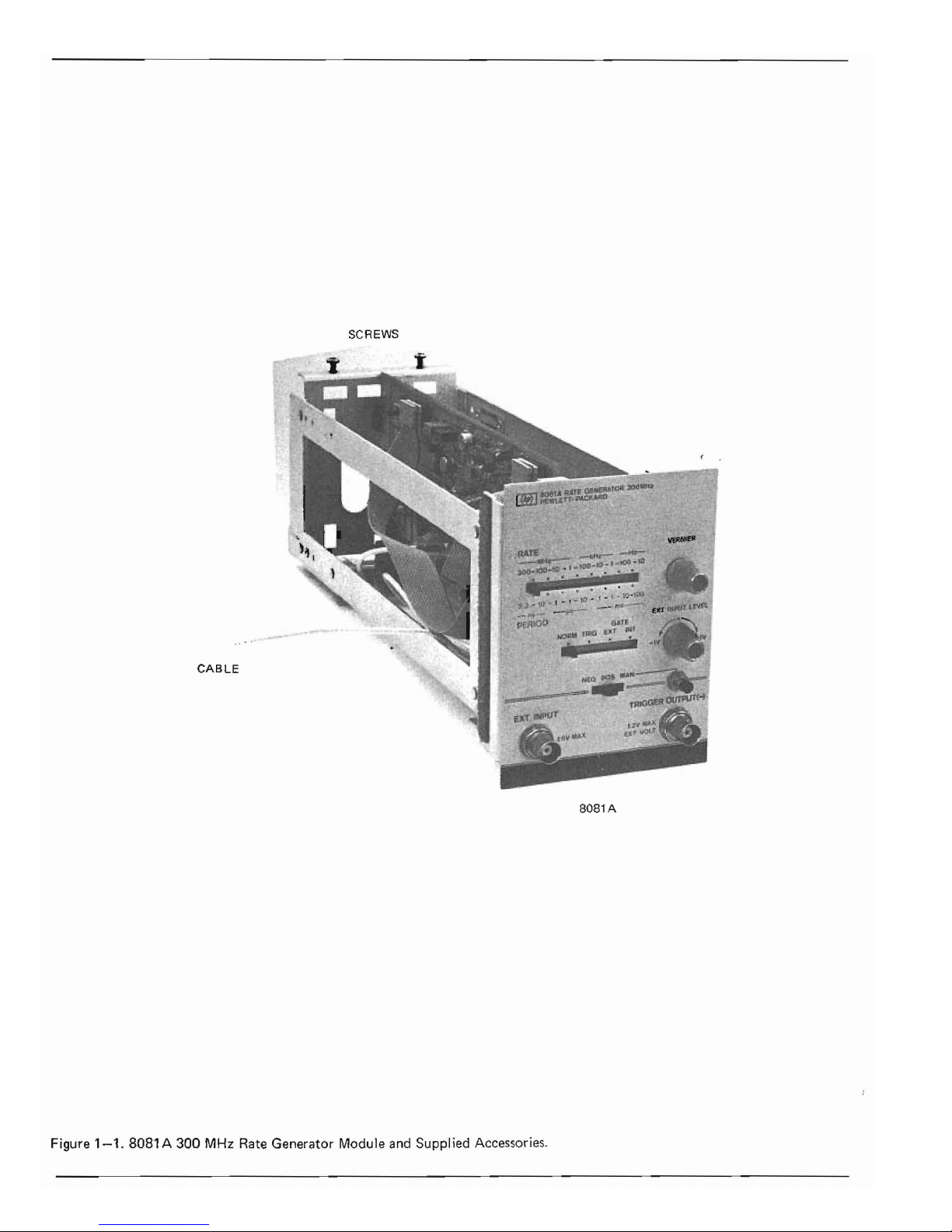
Figure
1-1.
8081 A 300 MHz
Rate
Generator Module
and
Suppl
ied
Accessories.
Page 7
,-------------------------------SECTION
1
"--~----------------------
GENERAL INFORMATION
1-1
INTRODUCTION
1-2
This
Operating
and
Service manual
contains
information
requiredtoinstall,
operate,
test,
adjust
and
service
the
Hewlett-Packard Model 8081 A
300
MHz
Rate
Generator
module.
Figure
1-1
shows
the
module
and
accessories supplied.
This
section
covers
instrument
identification,
descrip-
tion,
accessories, specifications,
and
other
basic informa-
tion.
1-3
A
microfiche
versionofthis manualisavai-
lable
on
4 x 6 inch
microfilm
transparencies
(order num-
ber
on
title
page). Each
microfiche
containsupto
60
photo-duplicatesofthe
manual pages.
The
microfiche
package also includes
the
latest
Manual Changes supple-
ment
as well as all
pertinent
Service Notes.
1-4
SPECIFICATIONS
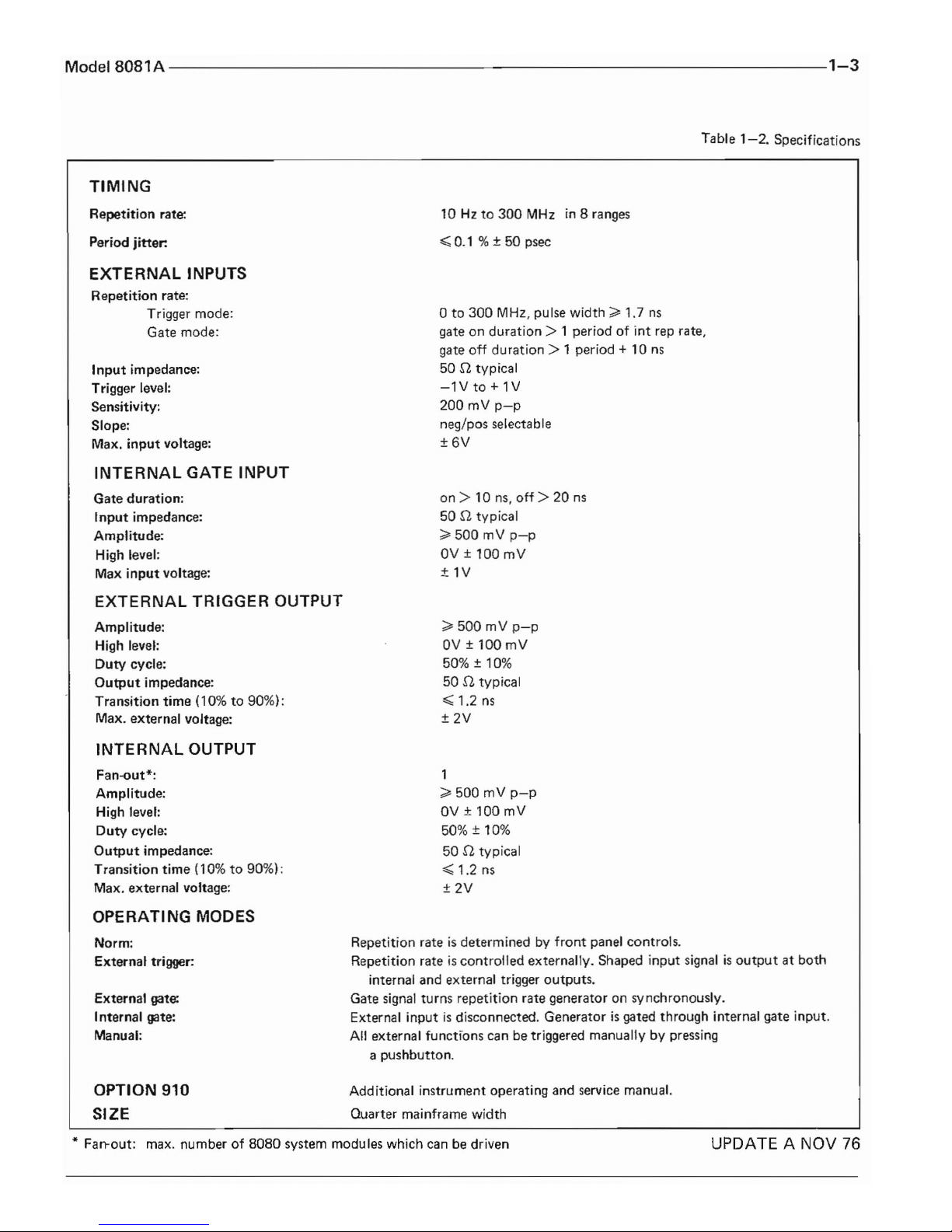
1-5
I
nstrument
specifications
are
listed in
table
1-2.
These
specifications
are
the
performance
standardorlimits
against
which
the
instrumentistested.
is
a significant changetothe
instrument.
The
last five
digits are assigned
to
instruments
sequentially.
The
con-
tentsofthis manual
apply
directlytothe
instrument
serial
number
quotedonthe
title
page.
For
instruments
with
lower serial numbers, refertothe
backdating
infor-
mationinSection8of
this
module
manual.
For
instru-
ments
with
higher serial numbers, refertothe
Manual
Change
sheetsatthe
endofthis
module
manual. In addi-
tiontochange
information,
the
Manual Change
sheets
may
contain
information
for correcting
errorsinthe
manual.Tokeep
this
manual as
up-to-date
and
accurate
as possible, Hewlett-Packard
recommends
that
you
periodically
request
the
latest Manual Change supple-
ment.
The
supplement
for
this
manualisidentified
with
this
manual's
print
date
and
part
number,
bothofwhich
appearonthis
module
manual's
title
page. Complimen-
tary
copiesofthe
supplement
are
available from
Hewlett-Packard.
HEWLETT-PACKARD
GmbH
[1536G00062
]
BOBLINGEN
..
Figure
1-1.
Serial Number Plate
1-6
SAFETY CONSIDERATIONS
1-11
DESCRIPTION
1-7
The
Model 8081 Aisa
Safety
Class 1 instru-
ment
(it has an
exposed
metal chassis
thatisconnected
to
earth
via
the
8080A
system
mainframe). This instru-
ment
has been designed
accordingtointernational
safety
standards
and
has
been
supplied in a safe
condition.
1-8
This
operating
and
service manual
contains
information,
cautions
and
warnings
which
must
be fol-
lowed
by
the
usertoensure
safe
operation
andtomain-
tain
the
instrument
in a safe
condition.
1-9
INSTRUMENTS COVERED BY MANUAL
1-10
Attachedtothe
insideofthe
instrument
side
frameisa serial
number
plate (figu re
1-1).
The
first
four
digitsofthe
serial nu
mber
0 nly change
when
there
1-12
The
Model
8081Aisa
0-300
MHz Rate
Generator
module
designedtoprovide a clock
source
for
another
8080
system
module.
The
8081 A has four
operating
modes:
Normal
Trigger
External Gate
Internal
Gate
In Normal mode,
the
rate
generatorisfree-runningatthe
repetition
rate
selected by
the
rate controls.InTrigger
mode,
the
rate
generatorisbypassed
and
thepuIse
outputismerely a
shaped
versionofa pulse
input
from
eitheranexternal
sou rceora manual
pushbutton.
In
External
Gate
Mode,
the
rate
generator
outputisgated
Page 8
Mainframeisrequired.
The
8080A
mainframe provides
housing and power supplies for
the
8081
A.
by a gate pulse
from
an external sourceora manual
pushbutton.
Internal Gate
mode
can
only
be useed with
an
8084A
Word
Generator
module.
The
trigger slope
polarity
and
threshold
levelofexternal gate/trigger
in-
putsisadjustable.
1-18
EQUIPMENT
AVAILABLE
1-13
The power supplies
for
the
8081 A are pro-
vided by
the
8080A
Mainframe.
1-15
The
only
option
for
the
8081 A Rate Gener-
atorisa second
copyofthe
operating
and service
manual
which
canbeobtained
by ordering
option
910.
1-19
The
8081 Aisone
of a
complete
range
of
rep. rate, timing and
output
modules
that
form
the
8080
high frequency pulse generator system. Repeti-
tion
rates range from
0-1
GHz
and
the
modules are
interchangeable
to
enable youtopurchase a system
exactly tailoredtoyour
requirements.
1-14
OPTIONS
1-20
RECOMMENDED TEST EQUIPMENT
1-16
1-17
EQUIPMENT REQUIRED BUT NOT
SUPPLIED
To
operate
the
8081 A module, an
8080A
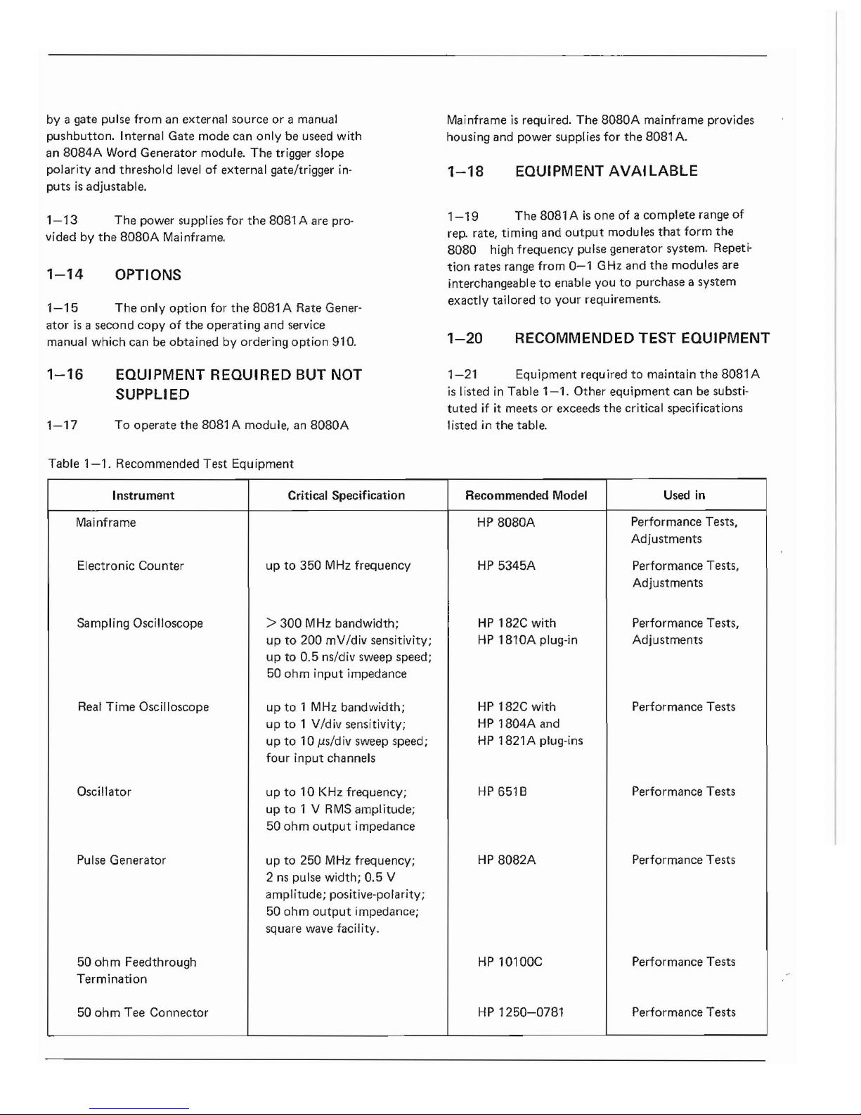
1-21
Equipment requiredtomaintain
the
8081 A
is
listedinTable
1-1.
Other
equipment
canbesubsti-
tuted
if it meetsorexceeds
the
critical specifications
Iisted
in
the
table.
Table
1-1.
Recommended
Test
Equi
pment
Instrument
Critical Specification
Recommended Model
Used
in
Mainframe
HP
8080A
Performance Tests,
Adjustments
Electronic
Counter
upto350
MHz
frequency
HP
5345A
Performance Tests,
Adjustments
Sampling Oscilloscope >
300
MHz
bandwidth;
HP
182C with
Performance Tests,
upto200
mV/div sensitivity;
HP
1810A
plug-in
Adjustments
upto0.5
ns/div sweep speed;
50
ohm
input
impedance
Real
Time
Oscilloscope
up
to1MHz
bandwidth;
HP
182C with Performance Tests
upto1 V/div sensitivity;
HP
1804A
and
upto10 Ils/divsweep speed;
HP
1821 A plug-ins
four
input
channels
Oscillator
up
to
10KHz
frequency;
HP
651 B Performance Tests
up
to
1 V
RMS
amplitude;
50
ohm
output
impedance
Pulse
Generator
upto250
MHz
frequency;
HP
8082A
Performance Tests
2 ns pulse width;
0.5
V
amplitude; positive-polarity;
50
ohm
output
impedance;
square wave facility.
50
ohm
Feedthrough
HP
10100C
Performance Tests
Termination
50
ohm
Tee
Connector
HP
1250-0781
Performance
Tests
Page 9
Model
8081A
-------------------------------1-3
Table
1-2.
Specifications
TIMING
Repetition
rate:
Period
jitter:
EXTERNAL
INPUTS
Repetition
rate:
Trigger
mode:
Gate
mode:
Input
impedance:
Trigger level:
Sensitivity:
Slope:
Max.
input
voltage:
INTERNAL
GATE INPUT
Gate
duration:
Input
impedance:
Amplitude:
High level:
Max
input
voltage:
EXTERNAL
TRIGGER OUTPUT
Amplitude:
High level:
Duty
cycle:
Output
impedance:
Transition
time
(10%to90%):
Max.
external
voltage:
INTERNAL
OUTPUT
Fan-out*:
Amplitude:
High level:
Duty
cycle:
Output
impedance:
Transition
time
(10%to90%):
Max.
external
voltage:
OPERATING MODES
Norm:
External
trigger:
External gate:
Internal
gate:
Manual:
OPTION 910
SIZE
10Hzto
300
MHzin8 ranges
~
0.1 % ± 50 psec
o
to
300
MHz, pulse width;;;'
1,7
ns
gateonduration>1periodofint
rep rate,
gate
off
duration>
1 period +
10
ns
50 n typical
-lV
to
+ 1V
200
mV
p-p
neg/pas
selectable
±6V
on>
10
ns,
off>20ns
50 n typical
~
500
mV
p-p
OV±100mV
±lV
~
500
mV
p-p
OV±100
mV
50% ± 10%
50
n typical
~
1.2
ns
±2V
1
~
500
mV
p-p
OV±100
mV
50% ± 10%
50
n typical
~
1.2
ns
±2V
Repetition
rateisdeterminedbyfront
panel
controls.
Repetition
rateiscontrolled
externally.
Shaped
input
signalisoutputatboth
internal
and
external trigger
outputs.
Gate signal
turns
repetition
rate
generatoronsynchronously.
External
inputisdisconnected.
Generatorisgated
through
internal
gate
input.
All
external
functions
can
be triggered
manuallybypressing
a
pushbutton.
Add itional
instrument
operating
and
service manual.
Quarter
mainframe width
* Fan-out: max.
numberof8080
system
modules
which can be driven
UPDATE A NOV
76
Page 10
.-----------------------------
SECTION 2
INSTALLATION
2-1
INTRODUCTION
2. Remove
the
upper
two
feet
from
the
rear
of
the
BOBOA
mainframe.
2-2
This
section
provides installation instruc-
tions
for
the
Model
BOB1A300
MHz Rate
Generator
module. It also includes
information
about
initial inspec-
tion
and
damage
claims,
preparation
for
use,
and
packag-
ing,
storage
and
shipment.
2-3
INITIAL
INSPECTION
2-4
Inspect
the
shipping
container
for
damage.
If
the
containerorcushioning
materialisdamaged,
it
shouldbekept
until
the
contentsofthe
shipment
have
been
checked
for
completeness
and
the
instrument
has
been
checked
mechanically
and
electrically.
The
con-
tentsofthe
shipment
shouIdbeasshown
in Figure
1-1.
Procedures
for
checking
the
electrical
operation
are
given in
Section
3. If
the
contents
are
incomplete,
if
thereismechanical
damageordefects,orif
the
8081
A
does
not
pass
the
operator's
checks,
notify
the
nearest
Hewlen-Packard
Sales/Service office. If
the
shipping
containerisdamaged,orthe
cushioning
material
shows
signsofstress,
notify
the
carrieraswell as
the
Hewlett-
Packard
office. Keep
the
shipping
materials
for
carrier's
inspection.
TheHPoffice
will
arrange
for
repairorrepla-
cement
without
waiting
for
claim
settlement.
2-5
PREPARATION FOR
USE
2-6
Installation in
8080A
Mainframe
ICAUTION]
The
following
installation
procedure
must
onlybecarried
outbyqual ified service
personnel.
3.
Remove
the
80BOA
mainframe
top
cover.
4. Insert
the
BOB1
A in
the
required
posi-
tioninthe
BOBOA
mainframe
(there
are
no
electrical
limitationsonthe
position).
5.
Secure
the
80B1 Atothe
8080A
main-
frame
using
the
two
screws provided.
6.
Connect
the
internal coaxial
cable
from
the
8081 Atothe
word
generator,
delay,
output
amplifier
modulesorto
remote
equipment
as required.
Connections
are
Internal
Output
and
Internal Gate. A con-
necting
cable
for
the
Internal
Output
is
supplied.
7. Replace
the
BOBOA
mainframe
top
cover.
B.
Replace
the
two
feetonthe
rearofthe
8080A
mainframe.
2-8
Operating Environment
2-9
The
8081
A will
operate
within
specifications
when
the
ambient
temperatureisbetween
OOC
and
550C.
2-7
To
operate
the
BOB1
A, it
must
firstbeinstal-
led in
an
BOBOA
Mainframeasfollows:
2-10
Storage and Shipment.
1.
Switch
the
mainframe
LINE
OFF/ON
switchtoOFF.
Disconnect
the
power
supply
cable
from
the
rearofthe
8080A
main-
frame.
2-11
The
BOB1Acanbestoredorshippedattem-
peratures
between
-40
o
C
and
750C.
The
instrument
should
be
protected
from
temperature
extremes
which
cause
con-
densation
within
the
instrument.
Page 11
2-12
If
the
instrumentistobeshippedtoa
Hewlett-Packard
Sales/Service Office,
attachatag
show-
ing
owner,
return
address,
model
number
and
full serial
number
and
the
typeofservice required.
The
original
shipping
carton
and
packaging material
maybere-usable
but
the
Hewlett-Packard
Sales/Service
office
will also
provide
information
and
recommendationsonmaterials
tobeusedifthe
original
packingisnot
available
or
re-usable. General
instructions
for
re-packing are as fol-
lows:
1.
Wrap
instrument
in heavy
paperorplastic
2. Use
strong
shipping
container.
A double-
wall
carton
madeof350-poundtest
material
is
adequate.
3.
Use
enough
shock-absorbing
material (3 (
to
4 inch layer)
around
all sidesofinstru-
menttoprovide
firm
cushion
and
prevent
movement
inside
container.
Protect
control
panel
with
cardboard.
4.
Seal
shipping
container
securely.
5.
Mark shipping
container
FRAG I
LE
to
encourage
careful
handling.
6.
In
any
correspondence,
refertoinstru-
mentbymodel
number
and
full serial num-
ber.
Page 12
RATE
•
--NHI.-
-k.ti::r-
-"'1:---
300-100-10'"•-100-10
- 1
-100-10
1
. 3 3 - 10 • 1 -1·10 -,-1~10-\00
PERIOD
VERNIER
2
'f)(T
tNPU1
l.fVEL
GATE !
/::'~
NORM TRIG EXT
tNt
,
...
,
3
_iii_iii
-IV
.,v
4
====="~=
5..
~AN
6.
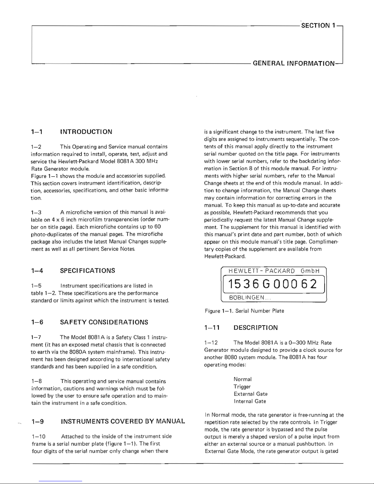
=
EXT
INPUT TRIGGER OUTPUT(-)
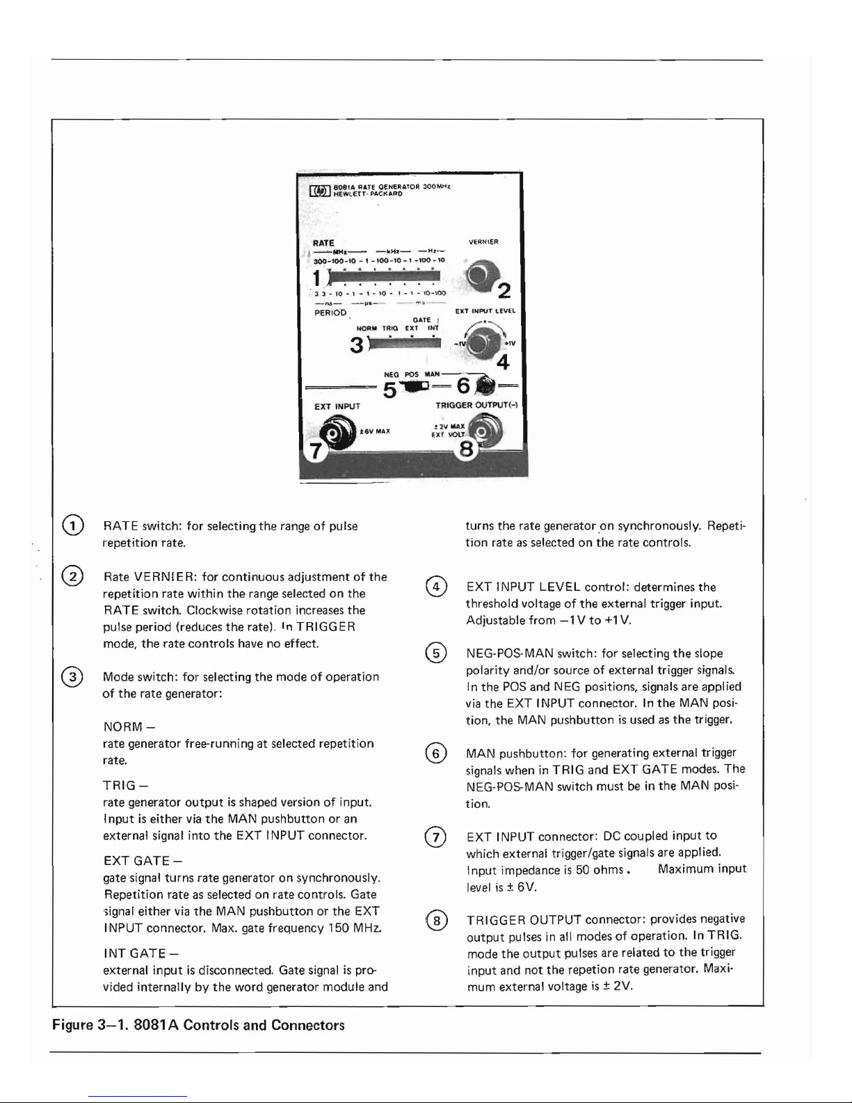
o EXT INPUT LEVEL
control:
determines
the
threshold
voltageofthe
external
trigger input.
Adjustable
from-1Vto+1
V.
@ NEG-POS-MAN switch:
for
selecting
the
slope
polarity
and/or
sourceofexternal trigger signals.
In
the
POS
and
NEG positions, signals
are
appl ied
via
the
EXT INPUT
connector.Inthe
MAN posi-
tion,
the
MAN
pushbuttonisused as
the
trigger.
G) RATE switch:
for
selecting
the
rangeofpulse
repetition
rate.
G Rate
VERNIER:
for
continuous
adjustmentofthe
repetition
rate
within
the
range selectedonthe
RATE switch. Clockwise
rotation
increases
the
pulse
period
(reduces
the
rate).InTRIGGER
mode,
the
rate
controls
have no effect.
o Mode
switch:
for
selecting
the
modeofoperation
of
the
rate
generator:
NORM-
rate
generator
free-runningatselected
repetition
rate.
TRIG-
rate
generator
outputisshaped
versionofinput.
Inputiseither
via
the
MAN
pushbuttonoran
external
signal
into
the
EXT INPUT
connector.
EXT
GATE-
gate
signal
turns
rate
generatoronsynchronously.
Repetition
rate
as selectedonrate
controls.
Gate
'iignal
either
via
the
MAN
pushbuttonorthe
EXT
INPUT
connector.
Max. gate
frequency
150
MHz.
INT
GATE-
external
inputisdisconnected.
Gate
signalispro-
vided
internallybythe
word
generator
module
and
Figure
3-1.
8081 A Controls and Connectors
(~)
turns
the
rate
generatoronsynchronously.
Repeti-
tion
rate as selectedonthe
rate controls.
MAN
pushbutton:
for generat;ng
external
trigger
signals
wheninTRIG
and
EXT GATE modes.
The
NEG-POS-MAN
switch
must
be in
the
MAN
posi-
tion.
EXT INPUT
connector:
DC
coupled
input
to
which
external trigger/gate signals
are
applied.
Input
impedanceis50
ohms.
Maximum
input
level
;s
± 6V.
TRIGGER
OUTPUT
connector:
provides negative
output
pulses in all
modesofoperation.InTRIG.
mode
the
output
pulses
are
relatedtothe
trigger
input
and
not
the
repetion
rate
generator. Maxi-
mum
external
voltage;s± 2V.
Page 13
SECTION 3
J
'-----------------------------
OPERATION
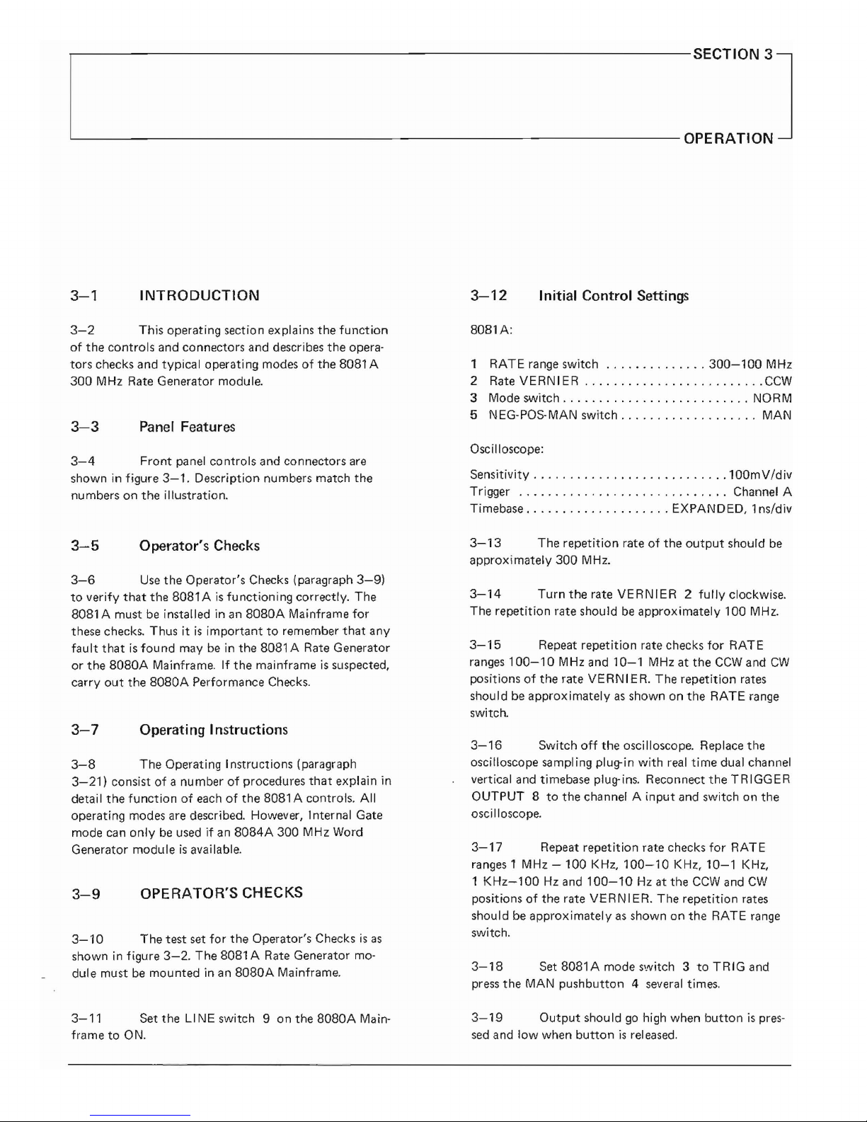
3-1
INTRODUCTION
3-12
Initial Control Settings
3-2
This operating section explains the
function
of
the controls and connectors and describes
the
opera-
tors checks and
typical
operatingmodesofthe 8081 A
300
MHz Rate Generator module.
3-3
Panel Features
3-4
Front
panel controls and connectors
are
shown in figure
3-1.
Description numbers match the
numbers on the illustration.
SOSl
A:
1
RATE
range switch
300-100
MHz
2 Rate VERN IER
CCW
3 Mode switch NORM
5 NEG-POS-MAN switch
MAN
Oscilloscope:
Sensitivity
100mV/div
Trigger Channel A
Timebase EXPANDED, 1ns/div
3-5
Operator's Checks
3-13
The
repetition
rateofthe
output
should
be
approximately 300 MHz.
3-6
Use
the
Operator's Checks (paragraph
3-91
to
verify
that
the
SOSlAis
functioning
correctly. The
SOSl
A mustbeinstalled inanSOSOA
Mainframe
for
these checks. Thusitis
importanttoremember
that
any
fault
thatisfound
maybein the
BOSl
A Rate Generator
or
the
80S0A
Mainframe.Ifthe mai nframeissuspected,
carry
out
the
SOSOA
Performance Checks.
3-7
Operating Instructions
3-8
The Operating Instructions (paragraph
3-21
I consist
of
a numberofprocedures
that
explain in
detail the
functionofeachofthe
80S1
A controls.
All
operating modes are described. However, 1nternal Gate
mode
can
onlybeusedifan
8084A
300 MHz Word
Generator moduleisavai
lable.
3-9
OPERATOR'S CHECKS
3-10
The test
set
for
the Operator's Checksisas
shown in figure
3-2.
The 8081 A Rate Generator mo-
dule must
be
mounted inanS080A Mainframe.
3-11
Set theLINE switch 9 on the
8080A
Main-
frame to ON.
3-14
Turn
the
rate
VERNIER2fully
clockwise.
The repetition rate should
be
approximately 100 MHz.
3-15
Repeat repetition rate checks
for
RATE
ranges
100-10
MHz and
10-1
MHz at the
CCW
and
CW
positionsofthe rate
VERNIER.
The
repetition
rates
should
be
approximatelyasshown on
the
RATE
range
switch.
3-16
Switch
off
the oscilloscope. Replace the
oscilloscope sampling
plug-in
with
real
time
dual channel
vertical
and
timebase plug-ins. Reconnect
the
TRIGGER
OUTPUT 8tothe channel A
input
and switch on the
osciIloscope.
3-17
Repeat repetition rate checks
for
RATE
ranges
1 MHz
-100
KHz,
100-10
KHz,
10-1
KHz,
1
KHz-l00
Hz
and
100-10
Hz at the
CCW
and
CW
positionsofthe rate VE RNI
ER.
The repetition rates
shouldbeapproximatelyasshown on the RATE
range
switch.
3-18
Set
BOB1A
mode
s'.'vitch3toTRIGand
press
the
MAN
pushbutton 4
several
times.
3-19
Output
shouldgohigh when
buttonispres-
sed
and
low
when
buttonisreleased.
Page 14

8080A
MAINFRAME
9
RATE
,--MH.--
-kH:r-
-Hl-
300-100-10
- 1
-100-10
- 1
-100
...
10
1
J~-
IU
- I - • -
I1J
- , . t -
11)-
iL'.l'J
P
'RIOI>
GAlE
t~OR"
HUG
EXT INT
VERN1£R
EXT INPUT
LEVEL
ascI
LLOSCOPE
WITH 1 GHz
SAMPLING
PLUG-IN
D
CH
A
50
OHM
COAXIAL
CABLE
Figure
3-2.
Test Set
for
Operator's Checks
NEG
pOs
ro\AN---~~
OSCI
LLOSCOPE
D
VERNIER
EXT
H4PUT
LEVEl
2
-,
GAtE
NQR,lOI
TRIO EXT
fN:r
J J - t - 1 - 1 -
~[JI
- I - 1
-'
·1
RATE
J
--I\lH.--
-kHl-
-H.;z;-
~O-100-'O
- 1 -
toO
-10
-~-100
- 10
. .
1
9
PULSE
GENERATOR
-------0---0
- - - - -
0-
--- - -
OUTPUT
500HM
TEE
50 OHM
COAXIAL
CABLES
DUAL
TIMEBASE
CHANNE
L PLUG·I N
VERTICAL
EXT
PLUG·I N INPUT
o
00
L....-
CH. -
CH.----'
A B
Figure
3-3.
Suggested Equipment Setup
for
Operating Instructions
Page 15

3-27
In
Normal mode,
the
repetition
rate genera-
torisfree-runningatthe
frequency
setonthe
rate
con·
trois.
The
pulse
outputisthe
sameason
the
oscilloscope
(the
trigger
outputisidenticaltothe
pulse
output).
The
pulse
duty
cycleis40-60%.
3-20
Set
BOB1Amode
switch 3toEXT. GATE
and
press
the
MAN
pushbutton.
The
repetition
rate
should
start
when
the
buttonispressed and
stop
when
the
buttonisreleased. When
the
buttonispressed,i.e.
when
the
gate opens,
the
first pulse should always
start
at
the
beginning. However, when
the
buttonisreleased,
i.e.the
gate closes,
the
last pulse may be
cut
short.
3-26
Normal Mode.
3-21
OPERATING
INSTRUCTIONS
3-28
Trigger Mode
3-22
A suggested
equipment
setup
for
the
Operat-
ing
Instructionsisshown in figure
3-3.
The
B081 A Rate
Generator
mustbemounted
in an
BOBOA
Mainframe.
The
following
procedureisdesigned
to
give a full
understandingofthe
functionofeach
of
the
8081 A
operating
modes.
3-23
Set
the
LINE switchonthe
8080A
Main-
frametoON.
3-29
In
TRIGGER
mode,
the
repetition
rate
of
the
outputisindependentofthe
internal
repetition
rate
generator.
The
output
is,
in fact, a pulse-shaped version
of
the
input
signal.
The
input
can be
either
external via
the
EXT INPUT
(-j)
or
local using
the
MAN
pushbut-
ton
®.
For external triggering, an external signal source
is
required.
The
test
setisas
showninfigure
3-3.
The
changes in
control
settings areasfollows.
3-24
Initial
Control Settings
8081A
CD
RATE range switch 1
MHz-100
KHz
~
Rate
VERNIER
CCW
~
Mode switch NORM
@ EXT INPUT LEVEL
+1
V
@ NEG-paS-MAN switch
pas
Oscilloscope:
Timebase
2 psec/div
Trigger Channel A internal
Pulse
Generator:
switched off.
8081A:
@ Mode switch
TRIG
@ NEG-POS·MAN switch
pas
Pulse
Generator:
Switch
pulse generator on.
SetpuIse
periodtoabout15fJ.sec.
Set
pulse
widthtoabout8fJ.sec.
Set
pulse
amplitudeto2V
and
polarity
to
pas.
Set
the
oscilloscopetotrigger
from
chan-
nel
B internally.
3-25
modes:
The
8081 A has
four
different
operating
Normal (NORM)
Trigger (TRIG)
External
Gate
(EXT GATE)
Internal
Gate
(INT GATE)
3-30
The
oscilloscope display should be as shown
in
figure
3-4.
The
8081 A
output
should
only
be
delayed
on
the
external
inputbythe
internal
circuitry
delayofthe
8081 A
EXTERNAL
I
L
INPUT
Ov
-L
I
RATE
ov
II
GENERATOR
-O.6V
I
OUTPUT
II
f
I I
---J
!--
fixed
delay
Figure
3-4.
Rate
Generator
Output
in Trigger Mode.
Page 16

3-31
Vary
the
EXT INPUT LEVEL switch ® and
note
that
the
trigger
output
disappears when
the
thre-
shold level reaches
approximately
+0.2V.
Set
the
exter-
nal
input
levelto-1
V.
3-32
Set
the
NEG-POS-MAN switch
@to
NEG.
Set
the
pulse
generator
output
polaritytonegative.
This gate signaIcan
come
from
either an external source (
via
the
EXT INPUT
connector
(J)
or
locally using
the
MAN
pushbutton
®. When
the
gate signal switches on,
the
first
output
pulseisalways startedatthe
beginning.
When
the
gate signal switches off,
the
pulseisterminated
immediately,i.e.
the
last pulse may be
cut
short.
3-37
In External Gate
mode
the
repetition rate
generator
outputisenabled/disabled by a gate signal.
3-33
The
oscilloscope display should be similar
to
that
showninfigure
3-4
except
that
the
external
input
is
a negative-going pulse.
3-34
Vary
the
EXT INPUT LEVEL switch ® and
note
that
the
trigger
output
disappears when
the
thre-
shold level reaches
approximately
-O.2V.
3-35
As
mentioned
previously,
the
pulse
output
in
trigger
mode
can also be
produced
using
the
MAN
pushbutton
®.
First set
the
NEG-POS-MAN switch ®
to
MAN.
This transfers
the
trigger
input
from
the
EXT
INPUT
connector
(J)
to
the
MAN
pushbutton
@ .
Set
the
oscilloscope timebasetoabout
0.2
sec/em and trig-
ger internally. Press
the
MAN
pushbutton
@ and note
that
the
pulse
output
goes high when
the
buttonispres-
sed and low when itisreleased.
The
EXT INPUT
LEVEL control
® has no
effectinthis
mode.
Internal Gate Mode
3-39
Set
the
NEG-POS-MAN switch @toPOS
and
the
EXT INPUT LEVE L control ®
to-1V.
Vary
the
rate VERNIER
C2>.
Note
that
the
last pulse may be
cut
shortbythe
gate turning
off
(see figure
3-5).
3-38
Set
the
Mode switch ®
to
EXT GATE.
Set
the
oscilloscope timebaseto2 usee/em and trigger inter-
nally. Press
the
MAN
pushbutton
and
note
that
the
rep.
rate generator runs
at
the
selected rate for as long as
the
buttonisheld down.
3-41
Internal Gate mode can
only
be usedifan
8084A
300
MHz
Word Generator moduleisavailable.
In
this
modeofoperation
the
gate pulse for
the
rate genera-
tor
comes
from
the
word generator via an internal con-
nection. This gate enables
the
rate generator
output
in
the
same way as an external gate.
The
purpose of this
mode
istoenable an
exact
numberofdata bitstobe
gated
outofthe
word generator.
3-40
External Gate Mode.
3-36
EXTERNAL
OV
INPUT
Gate on
Gate off
RATE
GENERATOR
Ov-------;
OUTPUT
Last pulse may
not
be completed
Figure
3-5.
Rate
Generator
OutputinExternal
Gate
Mode.
Page 17

,.------------------------------
SECTION 4
L--
PERFORMANCE TESTS
4-1
INTRODUCTION
EQUIPMENT
4-2
The procedures in this section test the Model
8081
A's
electrical performance using the specifications
of
Table
1-2asthe performance standards.
All
tests
can
be
performed
without
accesstothe interiorofthe in-
strument. A simpler operational test
is
included in
sec-
tion
3 under Operator's
Checks.
Counter HP
5345A
PROCEDURE
4-3
EQUIPMENT REQUI RED
1.
Setupthe equipmentasshown in figure
4-1
and
set
the controlsasfollows:
4-4
Equipment required
for
the performance
tests
is
listed in the Recommended Test Equipment table
in section
1.
Any
equipment
that
satisfies the critical
specifications given
in the table
canbesubstituted
for
the recommended model.
8081A:
RATE
range
,
300MHz-l00MHz
Rate
VERNIER
CCW
Operating Mode switch NORM
NEG-POS-MAN switch
POS
4-5
TEST RECORD
SPECI FICATION
DESCRIPTION
2.
Using the counter, measure the Model
8081
A out-
put frequency at the
following
repetition rate
settings.
8081A
RATE
VERNI
ER
RESULT
300MHz-100MHz
CCW
>300MHz
300MHz-100MHz
CW
<100MHz
100MHz-
lOMHz
CCW
>100MHz
100MHz-
10MHz
CW
<
10MHz
1
OM
Hz-
1MHz
CCW
>
10MHz
10MHz-
1MHz
CW
<
1MHz
1
MHz-100KHz
CCW
>
1MHz
1
MHz-100KHz
CW
<100KHz
100KHz-
10KHz
CCW
>100KHz
100KHz-
10KHz
CW
<
10KHz
10KHz-
1KHz
CCW
>
10KHz
10KHz-
1KHz
CW
<
1KHz
1
KHz-100Hz
CCW
>
1KHz
1
KHz-100Hz
CW
<100Hz
100Hz-
10Hz
CCW
>100Hz
100Hz-
10Hz
CW
<
10Hz
o
8080A
MAINFRAME
808lA
4-6
The resultsofthe performance tests
can
be
tabulated on the Test Record at the endofthe procedures. The Test Record lists all
of
the tested specifica-
tions and
their
acceptable limits. Test results recorded at
incoming inspection
canbeused
for
comparison in
troubleshooting and after repairs or adjustments.
4--7 REPETITION RATE TEST
The
output
frequencyofthe Model 8081 Aischecked
over the
full
repetition rate
range.
Repetition Rate
.,
10Hzto300MHz
Figure
4-1.
Repetition
Rate
Test Setup
Page 18

4-8
TRIGGER OUTPUT TEST
3.
Measure
Amplitude, Baseline and
Duty
Cycle.
SPECIFICATION
Trigger
Output
Pulse
,-.6V±50mV
to
OV ±
50mV
Duty
Cycle 50 % ± 10 %
I-t
on
J-t
Off-J
Baseline
DESCRIPTION
The trigger
outputpuIse
parameters
are
tested.
Amplitude
shouldbe. ,
6V±50mV
Baseline should
be
OV±50mV
Duty
Cycle
shouIdbe
50 %~10 %
ton
x 100%
period
4-9
EXTERNAL TRIGGER MODE
(SLOW) TEST
Duty
cycle =
o
SAMPUNG
OSCI
LlOSCOPE
D
01
8080A
MAINFRAME
80S1A
Figure
4-2.
Trigger
Output
Test Setup
SPECI
FICATION
EQUIPMENT
The repetition rate
outputiscontrolled externally. The
trigger and internal
outputs
are
pulse-shaped versions
of
the trigger input.
Sampling oscilloscope
HP
182C Mainframe
with
1810A
plug-in
DESCRIPTION
PROCEDURE
1.
Set
up the equipmentasshown in figure
4-2
and
set
the controlsasfollows:
The
functionofthe Model 8081 Aistested in external
trigger mode using
an
external sinewave generator
to
apply a trigger signalof10KHz.
so
OHM
TERL4lNATlON
,
REI>,L
TIME
OSCILI,OSCOP~
RATE
range
300MHz-100MHz
Rate VERNIER ,.., ,
CW
Operating Mode switch NORM
NEG-POS-MAN switch
POS
8081A:
Oscilloscope
50QHM
T£~
2.
Sensitivity..,
200mV/div
Trigger internal
Timebase mode expanded
Timebase - direct 20ns/div
Timebase - expanded 2ns/div
Set
Frequencyto100MHzonscreen
using Rate
VERNIER.
Figure
4-3.
External Trigger Mode (Slow) Test Setup
EQUIPMENT
Oscillator ,
HP
651
B
Real
Time Oscilloscope
HP
182C Mainframe
with
1804A
and 1821 A plug-ins
50 Ohm Feedthru Termination
HP
10100C
/
Page 19

PROCEDURE
1.
Set up the equipmentasshown in figure
4-3
and
set
the controlsasfollows:
5.
Set
NEG-POS-MAN switchtoNEG
and repeat
steps
3 and 4 observing the
pulses.
The Model
8081Aoutput
shouIdtrigger on the negative
half-cycles
of
the oscillator output.
8081 A:
SPECIFICATION
RATE
range
100KHz-10KHz
Rate
VERNIER
CCW
Operating Mode switch
TRIG
EXT
INPUT
LEVEL
center
NEG-POS-MAN switch
pas
4-10
EXTERNAL
GATE MODE (SLOW)
TEST
Oscilloscope:
Gate
signal
turns
rep.
rate generator on synchronously.
Sensitivity (both channels) 1
V/div
Trigger.
, external
Timebase main 20ps/div
Oscillator:
DESCRIPTION
The functionofthe Model
8081Ais
tested in external
gate mode using
an
external sinewave generatortoapply
a gate
signalof10KHz.
Frequency
10KHz
Amplitude
1VRMs
3.
Check
that
during the positive slopeofthe oscilla·
tor
output
a positive pu
Ise
output
occurs.
4.
Turn
EXT
INPUT
LEVEL
control
from
positive
to
negative and observe waveforms.
so
OHM TEE
SQOHM
TERMINATION
REAl.
,IME
OSCU.LOSCOPE
Figure
4-4.
External Gate Mode (Slow) Test Setup
EQUIPMENT
Oscillator ,HP651
B
Real
Time Oscilloscope
HP
182C Mainframe
with
1804A
and 1821 A plug-ins.
50 Ohm Feedthru Termination
HP
10100C
i*--
Propagation
delay
I
Display oscillator
output
and Model 8081 A
output
on screen
8081A
OUTPUT
2.
OSCILLATOR
OUTPUT
PROCEDURE
OSCILLATOR
OUTPUT
8081 A
OUTPUT
Threshold
lever"""+1V
-1V
1.
Setupthe equipmentasshown in figure
4-4
and
set
the controlsasfollows:
8081A:
RATE range. ,
100KHz-10KHz
Rate
VERNIER
CCW
Operating Mode switch
GATE
EXT
EXT INPUT
LEVEL
center
NEG-paS-MAN switch
pas
Page 20

Oscilloscope:
4-11
MANUAL
FUNCTION TEST
\
Sensitivity (both cha nnels) 1VIdiv
Trigger external
SPECI FI
CATION
Timebase, main
20~s/div
All
external functions canbetriggered manually by
pressing a pushbutton.
Oscillator:
o
00
500HM
HRMINATJON
SOBOA
MAINfRAME
SOS1A
REAL
TIME
ascI
LLOSCO~E:
Frequency 10KHz
Amplitude 1
VRMs
Display oscillator
output
and 8081 A
output
on
screen.
2.
3.
Check
that
during
the
positive slopeofthe
oscilla-
tor
output
a pulse burst appears.
Figure
4-5.
Manual Function Test Setup
EQUIPMENT
Threshold level
OSCILLATOR
OUTPUT
I I
I I
I I
~
r--Delay
of
1/2
period
8081A
i,hnnnn
rl
-
OUTPUT
-----.lJ
UUUUU
~
OV
Real
Time Oscilloscope
HP
182C Mainframe
with 1804A and 1821 A plug-ins
PROCEDURE
1.
Set up
the
equipmentasshowninfigure
4-5
and
set the controls
as
follows:
8081
A:
4.
Turn
EXTINPUT
LEVEL control from positive
to
negative and observe the waveforms.
RATE range
100KHz-10KHz
Rate VERNIER ,..,
CCW
Operating Mode switch GATE
EXT
EXT
INPUT LEVEL -
NEG-POS-MAN switch ,
MAN
Oscilloscope:
OSCILLATOR
I I
OUTPUT
-+
__
I_
I I
I I
I I
I I
I I
I I
I I
8081A
IlJU
OUTPUT~
~__~
I
I
I
I
I I
I I
11nJllUlJlJt:
2.
Sensitivity , 1V/div
Trigger, , , internal
Timebase, main ,
10IlS/div
Press
MAN
pushbutton.Aslongasthe
Man
button
is
pressed a pulse train should be visible
~MAN
button--..J
I pressed I
_llll~11Ill·I.lml-UIJ/JINI.ll-
OV
Threshold level
--+
+1
V
-1V
Note
that
the last pulse will be
cut
offassoon
as
the
gate closes.
3.
Set
the
OperatingMode switch to T
RIG.
Press the
MAN
pushbutton.Aslongasthe
MAN
button
is
pressed the
output
should be
OV.
5.
Set
the
NEG-POS-MAN switch to
NEG
and repeat
steps 3 and 4 observing the pulses.
The
8081 A
output
should be gated on
the
negative half-cycles
of the oscillator output.
r-
MAN
button~
pressed I
Page 21

SPECI
FICATION
SameasEXTERNAL
TRIGGER
MODE (SLOW),
para-
graph
4-9.
4-12
EXTERNAL
TRIGGER
MODE (FAST)
TEST
Oscilloscope:
Sensitivity
200mV/div
Trigger external
Timebase mode expanded
Timebase - direct 20ns/div
Timebase - expanded 0.5ns/div
OESCRI PTION
2.
Adjust the
Model8081A
EXT
INPUT
LEVEL
controltoobtain a stable
50%
duty
cycle display.
A high frequency test
of
the Model
8081
A external
trigger mode using
an
externalpuIse
generatortoapply a
trigger signal
of
250M
Hz.
3.
Each
trigger pulse
from
the pulse generator should
release
one
outputpuIse
from
the Model 8081 A.
Check
that
the display
has
a frequency
of
250M
Hz.
EXTERNAL
GATE MODE (FAST)
TEST
SameasEXTERNAL
GATE
MODE (SLOW), paragraph
4-10.
4-13
SPECIFICATION
SAMPLING
OSCILLOSCOPE
DESCRIPTION
Figure
4-6.
External Trigger Mode (Fast) Test Setup
EQUIPMENT
The maximum external
gate
frequencyofthe Model
8081 A
is
tested in external gate mode usinganexternal
pulse generator
to
apply a gate signalof150MHz.
SAr,.lPLIfIlG
OSCII,.LOSCOPE
1.
Set up the
equ
ipmentasshown in figure
4-6
and
set
the controlsasfollows:
PROCEDURE
Pulse
Generator
HP
8082A
Sampling Oscilloscope
HP
182C
with
181
OA
plug-in
Pulse
Generator:
Figure
4-7.
External Gate Mode (Fast) Test Setup
Repetition rate 250MHz
Pulse
width
2ns
Amplitude
0.2 V
Polarity positive
EQUIPMENT
Pulse
Generator
HP
8082A
Sampling Oscilloscope HP 182C
with
1810A
plug-in
8081A:
RATE
range -
Rate
VERNI
ER
_ -
Operating Mode switch
TRIG
EXT
INPUT
LEVEL
center
NEG-POS-MAN switch
POS
PROCEDURE
1.
Set up the
equ
ipmentasshown in figure
4-7
and
setupthe controlsasfollows:
Page 22

Pulse
Generator:
Repetition rate 150MHz
Pulse
width
square wave
Amplitude
0.2 V
Polarity
........................•..
positive
8081 A:
RATE
range
300MHz-l00MHz
Rate
VERNIER
CCW
Operating Mode switch
GATE
EXT
EXT
INPUT
LEVEL
center
NEG-paS-MAN switch
pas
2.
3.
Oscilloscope:
Sensitivity
200mV/div
Trigger external
Timebase mode ,
..
expanded
Timebase - direct 20ns/div
Timebase - expanded 5ns/div
Adjust the EXT INPUT
LEVE
L control
for
a
stable 150 MHz pulse presentation on the display.
Observe
that
each
external gate pulse
releases
two
8081Apulses.
Page 23

Table
4-1
Performance Test Record
Hewlett-Packard
Tested
by
Model 8081 A
Date
300MHz Repetition Rate Generator
Serial No.
Paragraph
Results
Test
Number
Min
Actual
Max
4-7
Repetition
Rate
10Hzto300MHz
<10HZ
-
-
>300M
Hz
4-8
Trigger
Output
Trigger
Output
Pulse:
-.6V±50mV
-0.55V
-O.65V
toOV±
50mV
-O.05V
+0.05V
Duty
Cycle:
50 %
± 10 %
40%
60%
Page 24

,-------------------------------SECTION
5
'-----------------------------ADJUSTMENTS
5-1
INTRODUCTION
5-2
This
section
describes
adjustments
required
to
return
the
Model 8081 A
Repetition
Rate
Generator
to
peak
operating
condition.
Includedinthis
section
are
test
setups,
and
checks
and
adjustments.
Removal and
replacement
procedures
are
given in
the
Disassembly/
Assembly
procedureinsection7.An
adjustment
locator
diagram is
includedinthis
section.
5-7
Make sure
that
only
fuses
with
the
required
rated
current
andofthe
specified
type
(normal blow,
ti me delay, etc.)
are
used
for
replacement.
The
use
of
repaired fuses
and
the
short-circuitingoffuseholders
must
be avoided.
5-8
Whenever itislikely
that
the
protection
has
been impaired,
the
instru
ment
must be
made
inoperative
and be secured against
any
unintended
operation.
5-3
SAFETY
CONSIDERATIONS
5-9
TEST EQUIPMENT REQUIRED
5-10
Table
1-1
containsa listoftest
equipment
and
test
accessories required in
the
adjustment
proce-
dures.
In
addition,
the
tables
contain
the
required mini-
mum
specifications
and
a suggested
manufacturer's
model number.
5-4
Although
this
instrument
has been designed
in
accordance
with
international
safety
standards,
this
manual
contains
information
and
warnings
which
must
be
followedtoensure safe
operation
andtoretain
the
instrumentina safe
condition
(see
SectionsIIand
III).
Service
and
adjustments
shouldbeperformed
only
by
qualified service personnel.
5-11
ALIGNMENT
TOOL
IWARNING I
5-12
A non-metallic
alignment
tool
mustbeused
when
making
any
adjustmentstothe
Model 8081
A.
5-14
After
making
the
adjustments,
carry
out
the
Performance
ChecksinSection
4.
Any
interruptionofthe
protective
(grounding)
conductor
insideoroutside
the
instrument
or
disconnectionofthe
protective
earth
terminal
is
likelytomake
the
apparatus
dangerous.
Intentional
interruptionisprohibited.
5-13
5-15
PERFORMANCE CHECKS
RELATED ADJUSTMENTS
5-5
Any
adjustment,
maintenance,
and
repair
of
the
opened
instrument
under
voltage
should
be avoided
as
much
as possible and,
when
inevitable,
should
be
carried
out
onlybya skilled
person
whoisawareofthe
hazard
involved
The
openingofcoversorremoval
of
parts,
except
thosetowhich access
canbegained
by
hand,
may
expose
live parts,
and
also accessible termi-
nals
may
be live.
5-6
Capacitors
inside
the
instrument
may
still
be
charged even if
the
instrument
has been
disconnected
from
its
sourceofsupply.
5-16
The
following
adjustments
must be per-
formedinthe
order
indicated in
the
procedures.
The
adjustments
can
notbeperformed
individually because
of
interaction.
5-17
After making
the
adjustments
the
following
related
adjustments
should
be checked.Ifthe
Model
8081 A
outputisconnectedtoa
word
generator,
the
word
generator
trigger level
must
be checked and, if
necessary, adjusted.
If
the
Model 8081 A
outputiscon-
nectedtoan
output
ampl ifier,
the
output
amplifier
duty
cycle
must be
checked
and, if necessary, adjusted.
Page 25

5-18
DUTY
CYCLE
AND
FREQUENCY ADJUSTMENTS
Frequency
adjust
307M
9M
Duty
Cycle
100M-10M
300M-100M
DESCRIPTION
These adjustments
set
up the correct
duty
cycle at high
and
low
frequencies and
cal
ibrate the frequency output.
An
oscilloscopeisusedtocheck
the
duty
cycle and a
countertocheck the frequency.
08081-66502
BOARD
A2
c:::J
R4
CJ
R8
c:J
R16
Figure
5-1.
Duty
Cycle Adjustment Test Setup
c::::J
R109
80SlA
S080A
MA~NFRAME
COUNTE.A
,
/
/,
//
/
, /
=
0
=0
/,/
~/
///
0
0
=
;,-
//
0
/ /
/'
o
SAMPLING
OSCILLOSCOPE
D
cI
8OS0A
MAINfRAME
8081A
EQUIPMENT
Sampling Oscilloscope
HP
182C Mainframe
with
181OASampl
ing
plug-in
Counter
HP
5345A
Figure
5-2.
Frequency Adjustment Test Setup
3.
Set
up the
equ
ipmentasshowninfigure
5-2
and
set
the
controlsasfollows:
PROCEDURE
80Bl
A:
1.
Setupthe equipmentasshown in figure
5-1
and
set
the
controlsasfollows:
8081A:
RATE
range
300-100MHz
Rate
VERNIER
Clockwise
Operating Mode NORM
Oscilloscope:
RATE
RANGE
300-100MHz
Rate
VERNIER
CCW
Operating Mode NORM
Counter:
Frequency
350MHz
Sensitivity 200mV/d
iv
Trigger internal
Timebase mode expanded
Timebase - direct 20ns/div
Timebase - expanded 1ns/div
4.
Adjust
A2R4toa frequencyof307MHz
± .5MHz
5.
Set the Model 8081 A RAT
Eta
100-1
OMHz.
and
rate
VERNIERtoCWo
2.
Adjust
A2R16
foraduty
cycleof....
50 % ± 10 %
6.
Adjust
A2R8toa frequencyof...
9MHz ±.1MHz
7.
Reconnect the equipmentasin figure
5-1
and
set
the controlsasfollows:
B081A:
ton
Duty
Cycle = x 100%
period
RAT
E range
300-100MHz
Rate
VERNIER
CCW
Operating Mode NORM
Page 26

Oscilloscope:
Sensitivity
200mV/div
Trigger internal
Sweep
Mode
expanded
Timebase
- main 20ns/div
Timebase-expanded
0.5ns/div
8.
Adjust
A2 R109foraduty
cycleof..
50
%±
10
%
9.
Connectanexternal
pulse
generatortothe
Model
8081 A EXT INPUT
connector
and
set
the
controls
as follows:
External Pulse
Generator:
Repetition
Rate 50MHz
Operating
Mode
square
wave
Ampl
itude
. . . . . . . . . . . . . . . . . . . . . . . . . . . . 1V
Polarity
positive
8081A:
RATE range
300-100MHz
Rate
VERNIER
,
CCW
Operating Mode GATE EXT
Input
Polarity POS
EXT INPUT
LEVEL
approx
+0.5V
Oscilloscope:
same
settings as
for
previous adjust-
ment
(step 7).
10. Check
the
duty
cycleofthe
first pulseonthe
display. If necessary,
readjust
Rl09
slightlytoset
the
duty
cycle
to
...............................
50% ±
10%
Page 27

,-------------------------------
SECTION 6
'---------------------------REPLACEABLE
PARTS
6-1
INTRODUCTION
6-7
The
information given for each
part
consists
of
the following:
6-2
This section contains information for order-
ing parts.
Table
6-1
lists abbreviations usedinthe
parts
lists and elsewhere
in
the
manual. Table
6-2
lists all
replaceable
partsinreference designator order.
Table
6-3
contains
the
names and addresses
that
corre-
spondtothe
manufacturer
code
numbers.
6-3
ABBREVIATIONS
6-4
Table
6-1
lists abbreviations usedinthe
parts lists, schematics and elsewhereinthe
manual. In
some cases
two
formsofthe
abbreviation are used,
one
all in capital letters,
and
one
partialorno capitals. This
occurs because
the
abbreviationsinthe
parts
lists are
always
all
capitals. However,inthe
schematics and
other
partsofthe
manual,
the
same abbreviations may have
upper and lower case letters.
6-8
a.
The
Hewlett-Packard
part
number.
b.
The
total
quantity
(Qty)inthe
instru-
ment. This
is
given
only
once
for each
part
-
at
the
first appearanceofthe
partinthe
list.
c.
The
descriptionofthe
part.
d.
A typical manufacturerofthe
partina
five-digit code.
e.
The
manufacturers' code number for
the
part.
ORDERING INFORMATION
6-5
REPLACEABLE PARTS
6-6
Table
6-2isthe
listofreplaceable parts and
is
organised as follows:
a.
Illustrated parts breakdowns for chassis
mounted
parts.
b.
Chassis
mounted
partsinalphanumerical
orderbyreference designator.
c.
Electrical assemblies and their compo-
nentsinalphanumerical
order
by reference
designator.
6-9
To
order
a part listedinthe
replaceable
parts
table,
quote
the
Hewlett-Packard part number, indicate
the
quantity
required, and address
the
ordertothe
nearest Hewlett- Packard office (listofSales/Service
offices
at
the
rearofthe
8080A
Mainframe manual).
6-10
To
orderapart
thatisnot
listedinthe
re-
placeable parts table, include
the
instrument model num·
ber,
instrument
serial number,
the
description and
function
of
the
part,
and
the
numberofparts
required.
Address
the
ordertothe
nearest Hewlett-Packard office.
Page 28

6-4-----------------------------------------------------------------------------
FRONT PANEL
(MP5)
FRONT PANEL (INSIDE)
A1S4
I[[IJ
A1S3
lillJ
A1S1
o
PlOW
1
MP1
R'O
Al
MP2
d
/
....
-
.......
( ;A1Rl
\
/
A1R1
<©I
MP6
CNONC
r--,
~o
•
01
Al
S2
08081 • 66501
l.-
___
J
A1S2
CON
TROL
BOAR
D
@
0)
(0
P/OWl
MP11
{TAPE,
ADHESIVE
BOTH
SIDES
/ TAPE, SCREENING
MP
10
....I
.
'.
~
'l.-
I-
10
o I
l""-
E
P/O
Wl
P/OW2
P/OW1
P/OW2
II
A1W2
~
A1W2
+
+
i
AIWl
:1
A2
•
A2
A2
A2
~
J6 I
I J7
J4(LOWER) J5(UPPER)
I
/2J1
\
BJ
IrR
L---..r&
II
§
h
II
A1W1
1 /
II
~
\
~2
A2X3/
I
Ie:
Ir--A1
A2X2
A3X/
MP3/
f---
"'"
MP3
f-
lJ
I
('
r;r{
.
.
A3
------
C
7 0 1
IT
-
r----
Rl
I-
10
f
01
r---
MP5
\ \
\MP
10
I
/
MP
12
"'"
MP7
MPll
MPa
MP9
F
igu
re
6-1.
8081 A Replaceable Parts
Page 29

-----------------------------------6-5
Table
6-2.
Replaceable
Parts
~8D~l
~O::lIA
I~S[HJMt~T
SERIOL
PRU
IX
F~
h"1
'EF~~"NC~
H-P PART
Ut$IG~ATCR
~UM~ER
Al
CijCUI-tt~CI
02
)9CEI-H5~2
'3
03091'005)3
MPl
~31C-l(~L
nz
0)7(-1(0
,~P
3
04C3-Q1t4
MP~
;E(ijl-((;",I
MPb
3101-0351
Mf
7
~<"'(
v-89
£
~
"p
II
146(\-1070
OESCRIPTIGN
3D
AY-CD~rpCL
to
AV-PATE
ec
AY-MCT~EP
KNOB
HCe
GLllJE
PC
PANEL fRONT
UP
PUSh
dUTTOi
PANEL
-SUB
!APE-INOL
.7S~
P-VAR
10K5~I_
CUL
AY-!
NIL
CUT
RATE
VE
R\\I\
t.: R
Page 30

6-6-------------------------------------------------------'---------
Table
6-2.
Replaceable Parts (cont'd)
MCr.H
dOdt.
~COEl
8C8U
l;~SlJCUMtf\ll
SE~
IAL
PI<OFI X
fN5T~UM€NT
5ER
IAlPREF I X
'jtl
~cll-
t:
e
~::l,
no
"~-RA
1E
A
I
l'8'J8t-6650
1
eo
A~-CO/VTROl
RH"HNCE
H-P
P'~1
IIISC~
IPT
IUN
I<EFEOINCE
Il-P
PAPT
UUC~
1P I
ION
~.:
5
1l>"<A
TOF
f\Ufo\i\EtI
"E5
IG/VAT
Uk
~UM8ER
REFt.c
NCE
H-P
p~q
OESCR1PTlCN
OESIGNArOR
~UMelR
AZ
1'12
~751-U1G
,-F
3.
10K
I~
.Z
PI.!
J757-C~38
R-F
5.1L~14
A,
<
67
GfSE-
4,25
R-fI.54Kl4
Al
RI
ZI00-2492
R-~AR
5K
Zlll
•
s_
A,
k14
J757-C~,,1
.-F
b25
I'
•
12.
Sw
AZ
RQO
J 15
7-1)~5.l
~-f
,J
.IK
11
A2
PIS
'17
51-')4
ZI
,-F
825
I'
•
II
Jrr
A2
R6G
07S7-C"Zl
l
R-F
15()H.1,
sw
AI
5 I
:WI-15~B
s.
Sl
IDE
DPOT
AZ>16
Zln\l-334<;
R-VAK
L.)~
-.!<H
A2
!dO
0757-G;94
R-F
51.
I U
A1
5Z
31)I-IZZ1
5w
PSTN SPCT
AZ
P7I
')6~8-blZ4
R-f
187
14
AI
53
C8C
15-~190,
SlIDE
AY
~Z
RI7
069&-3~~6
Q-F
.!B3
It
.1251'1
AL
53
5)"J-~~40
SP,
[NCDETEl'iT
AL
,18
J157-C~IZ
"of
.1&5
It
.IZ5~
AZ
P7Z
06S8-3lol
R-F
15u
S(
olL5.
Al
54
v~CI5-619J]
SLIDE
AY
A2
R
19
1<><;E-
H55
<-F
536
I~
.IZ,_
A2
P73
J6~8-3;PI
R-F
150
5t
.IL
5.
Al
kl)
")698-44,5
R-F
5J6
It
.125"
AZ
R74
06<;8-
4l]J
R-f)95t
.IZ5.
~
I
54
5,)2J-~~loiO
SP~
INGDE
TE~1
AZ
"
ZI
07~7-C4,1
R-F
>lZ5
If
.l25"
A2
R15
OeSS-4IJO
R-F
39
51
.IZ5.
AZ
pn
96GB-3Z5d
R-F
;
.30Kll
AZ
~L2
,)7,7-04Z\
<-F
8Z'>
14
• J
2.
5".
~Z
R23
l6<;8-3~~4
R-F
316
IX
.IZ5w
.Z
R77
l6~~-32'>I
P-f
,.
lC>K
I(
AZ
Q24
)6
sa-3444
R-F
JII>
U
• IZ
5.
AZ
~
78
l75
7-Cl
d3
R-F
2
KI'
.125~
F
AZ
R25
•
)157-041:>5
~-F
l(l":iKl:t
.[l5
•
A2
I'
79
0757-
t 41
~
R-F
'dl
l(
•
125_
AZ
"
Zc
C757-(443
k-f
IIn1
•
l25_
AZ
P~0
0"
7-0
.1"
R-F
,,81
l(
.1l5.
AZ
,8L0757-04lZ
R-F
365
U.
.IZ
,~
42
'L
I
''157-C2ii::
to.-f
Znt
.ll5.
F
.2
Q2u
.")157-C~~~
<-F
5.
lin:;
~l
R~Z
)757-[l~IZ
R-F
juS
U
.IL5.
A2
"Z'1
d698-H7~'-F
14~
L(
•
L23..-
A2
R
M3
06<;8-):'46
R-F
3d)
1(
.IZ5~
AZ
>
3J
J~57-G43.t,
'-F
3
.,,5~ll
AZ
Rli4
OfGM-4,7"
R-f
14~
Lt
.1l5_
AZ
r;}
I
C6<;E-33H
R-F
51
5~
.IZ5~
'Z
PA5
J)6~8-4':'
79
K-F
14K\(
.IZ5.
AZ
R
M6
C6SS-
337M
R-f
51
5~
.IZ5.
AZ
"32
CEI:-(CZ5
R-F
IbU
5~
.Z5.
AZ
R33
,)6SB-J378
R-F
51
5~
.125.
A2
~
07
C6q-3H~
R-F
51
~~
.12,"
A2
~J';
(6S8-331M
.-f
51
,~
.l~:iw
AZ
_88
00<;6-311rl
'-F
;1
5(
•IZ5.
A2
H.
p::
C6~8-
33H
>-~
51
5"
• 12
~\tI
AZ
R89
l,,9d-,J78
~-f
51
,f
.I".
MOll;:t
b(~IA
AZ
RJ6
.'69B-4479
R-F
14KH
.IZ5.
AZ
P
90
06S8-<,428
R-fI.6'>KI (
AZ
P9
L
0707-0433
R-F
3.
3ZK
U
INS T
>J
M~NT
SE~1
~l
PREF])
AZ
R37
O,,<;l-~~j<;
R-F
14KI(
•
1,5.
AZ
K)d
169>1-44
7~
R-F
14K 1(
.125""
AZ
1'92
v751-0~3]
P-F
J.
3ZKL
~
~
,
C8C81-6650Z
BO
AY-RATE
AZ
"
3S
C6St-<,4,S
i<-F
14KI(.125w
AZ
R93
06SB-3444
R-F
)1"
I(
~
12:>
...
4Z
R41
J6~&-44
is
P-F
L~K
a
.125.
AZ
"<;4
.)bC;8-44~d
R-F
..
Q 2
U
.IZ
~.
REF~REac~
H-P
PART
OESCRIPlI
C~
REFERE;.CE
~-P
PA>T
DESCRIPTl,lN
Al
R41
06G6-4479
R-F
14n
~
•
l25w
AZ
.95
0675-IOZ1
.-F
IKlut
•IZ5.
DESIGNATOR
NUMeER
DESIGNATOR
Nu~BER
A2
R91>
,1757-0405
R-f
11>2
I'
•
IZ5~
A2
CI
·1160-2,)55
(-F
.DIUF
A2
R4Z
0757-1424
O-F
L.IK
I(
•
U5.
100~
A2
t4
9100-0341>
eO[L
F
XD
AZ
~43
07
57-~4Z4
R-F
l.IKll
.IZ
5.
A2
).
97
01~7-\l405
K-F
16,
l(
•
IZ'.
AZ
CZ
;)
18()-CZ<;1
C-F
ILF 35V
A2
lS
9100-n346
COIL
FX
0
A2
R
44
(757-
C4Z4
Q-F
I.IKI'
•
IZ5.
AZ
R98
0/57-0273
R-F
l.01K
It
AZ
C3
))B\'-lZ~1
C-F
IUF
35~
AZ
R45
0757-.'424
"-I'
L.l~H
• L
25_
AZ
.9S
J757-IC9~
R-I'
I
.47KI
t
A2
C~
0180-C22"
C-F
J3UF
10~
AZ
L"
9170-0029
FERR
(lE
8EAO
AZ
.46
015,-)4,,4
F-F
I.IKI~
.125.
AZ
RIOO
0757-04Z4
R-F
1.LK1;
.125.
A2
C5~180-82ZS
C-f
nuF
I~V
A2
l7
9170-1:029
FtRRITE
8EAO
A2
Rl'31
0757-043d
R-F
5.11KL~
AZ
1 6
9110-00Z9
FERRITE
BEAU
AZ
047
:qS7-~.c,24
P-F
I
.I~
11
.IL5.
A2
C"
G1
00-C229
C-F
33Uf
IUV
AZ
L9
9110-()CZ9
FERRITE
dEAO
AZ
.4~
C6<;O-~~21,
P-F
l.o9KIl
AZ
o<lOZ
0757-043d
R-F
'>.IIKU
A2
C7
')
tBO-C<;~
C-
F
33uF
IL\I
AZ
lI-)
9[,TQ-3147
COlt-F
tlF
1')Uf
AZ
R4~
·~oS~-';;El
o-F
150
5~
• IZ
5.
AZ
RI03
06S8-0/J8~
R-F
2.1'>~1
t
A2
C8
0160-347C
C-F
.LllUF
5JKV
A2
R5J
00B3->lZ45
R-F
82JKH
.25.
AZ
1<104
'l6SB-4428
R-F
1.6,iKU
AZ
CS
OlfC-lE
if
C-F47PF
ZO~~DC
Al
Ll4
'1100-3147
COll-F~FIJUF
A2
~
~
1
C66:!-
E2~S
R-F
8Z0K;(
• Z,W
AZ
Rl
O~
)
157-v
422
R-F
'lOy
I'
.125.
AZ
CD
116('-1114
C- f
•~7UF
25V
A2
LIS
91vQ-3147
COlt-F
liF
I~UF
A2
Rl~v
00SB-4479
R-F
14KU
.IZ5.
AZ
Llo
9100-;139
Cull
INllUC
75U~
AZ
.5Z
G6B3-~Z45
_-F
8211K5t
.25_
AZ
CII
.)
160-24ie
C-F
.01IJF
50K~
AZ
lI7
~100-Jl41
CO
Il-
F~F10UF
AZ
R53
:1683-8,45
_-F
>lZ()K5t
.25
"
A2
RI07
J757-0411
R-f
562
1,
.ll5w
AZ
CI2
JI60-347"
C-F
.(;
lUF
5~K~
A2
RS':'
,lvB
3-8Z45
R-F
~20jC;5'~
.25.
A2
plOd
06se-~479
R-F
14KU
.12j""
AZ
CI3oIH-3410
L-F
•
<'l
OF
5()K~
A2
01
Ido;-OZO~
TRAI<5ISTUR
AZ
I'
55
')~ij;-d2it~
~-F
~ZllK51
.Z5
"
AZ
"'109
2100-
3
3~9
R-VAR
100
-tiOl
AZ
Cl~
i)
t60-3470C-
F
.0IUF
;OK~
AZ
~2
IB
53-0Z
84
TRANSISTOR
AZ
R5i>
0751-C3~~
R-
F
75
H
•tZ5.
A2
RI\)06SB-74b3
R-fBZLO
t
.U5.
A2
CI5
1160-34
7·)
e-F.)lUF
5')K~
AZ
03
I
8~4-
C215
X,TR51NPN
A2
~
III
06S8-
HII
R..F
30
51
.IZ5_
AZ
AZ
04
1854-0392
X5TK
S I
/VPN
A2
k570,
0'-
C42Z
R-F
909
1%
•
115
~
CI6
'I
16~-;4
i(
C-F
.01\JF
50KV
AZ
o,l5
1853-,1'186
XSTR S I
PI"P
AZ
P,58
0751-0~22
~-F
9('9
t,
.IZ5.
A2
RIIZ
06S>I-3;7~
Q-F
085t.IZ5"
AZ
C17
OloO-347C
C- F
.0IUF
5JK~
AZ
R59
06Sd-4418
I'-F
205
I
~
.IZ5~
AZ
P
113
J6S€-33H
R-F
0>1
51
.125.
A2
cIa
~l<O-C5q
C-F
15i)l'PF
'-,I)\)II
AZ
Jo
185~-C~9l
XSTR
S I
/VP~
AZ
~6J
C157-
CZ73
R-F
3.
~IKI~
AZRII
~
0698-3111
R-F
j()
5t
.IZ5.
AZ
CI9
(116J-3716
C-
f
.OUUf
Ij
'Z
5')
AZ
Q7
1853-
00,,6
XSTF<51PNP
AZ
R61
~1698-44
7q
R-F
I~KU
.125_
A2
R
ll5
0"<;8-517Z
R-F
Il
5(
.1l5.
AZ
CZO
Q18t-1735
C-F
.22UF
3,~
AZ
OM
ld54-039Z
xsrR
s {
NPN
AZ
F<
110
OO<;8-~172
l(-F
13
5t
•IZ5_
AZ
C21
AZ
u<;
t85~-CZI5
XS
TR
51
NPN
AZ
P,6Z
16<;e-~4;<;
R-F
14K
It
.12S.
~18o-01S7
C-f
2.ZVF
20~
A2
010
Id53-0036
X5TR-PNPSICHIP
AZ
R63
()757-·)~2rl
R-F
15v
U
• IZ
5.
AZ
RII7
0757-C~38
R-F
5.11
KI"
AZ
eLl
o
L<lo-C",E
C-F
22\Jf
15\1
AZ
k64
\lb~o-
D
7b
P-f515%
.IZ5W
AZ
RIl6
0757-e~3a
R-f
5.II~H
AZ
CZ3
1180-,208
C-F
22,1UF
lOt
L)~
.Z
y 1 L
lE53-0036
X5TR-P~P
S I
C~IP
AZ
R65
0757-C27"
p-F
3.16K
I'
AZ
RI19
01><;8-3376
R-F
51
,.
.Ih.
A2
C
24
016U-2C~5
C-F
.IlIUF
IOO~
AZ
OIZ
1>153-0036
X5TR-PNP
SI
C~IP
AZ
R66
0157-0417
R-F
562
It
.IZ5.
AZ
RIZO
00<;8-
337d
R-F
51
5(
.125.
AZ
CZ5
o
I~O-
34,(
C-F
• DIUF
50K~
AZ
U13
1853-0.1)~
XSTR-PNP
S I
CHIP
A2
Ol~
1853-
COb
XS
TR-P~P
51
CHIP
A2
CZ"
o
10C-
ZC~
5
L-F
.0IOF
l\1(1~
A2
015
18'>3-003~
XSTR-PNP)ICHIP
A2
C27
Olfa-H7:
C-F
.0IUF
5uK~
AZ
C2B
018()-1704
C-F
47uF
6~
AZ
<oll6
IB~3-C036
XS
TR-PNP
SI
CHIP
AZ
Po
I,
I
Ot<:a-
~4~3
R-F
ZR7
1%
.IZ5.
AZ
CZ~
016Cf-34)0
C-F
• (!IUF
50K~
A2
\117
Id53-0030
XSTR-P/vP
S I
CHIP
A2
RIZ 2
·)6S8-340
R-F
281
U
.IZ5_
AZ
C31~'160-347(1
C-F
.'110F
50KV
AZ
OZO
1853-(1036XSTR-P/vPSICHIP
AZ
RIZ 3
;/757-J44C
.-
F
7.
5K
I
~
.125.
AZ
OZI
185,3-
oe36
xsrR-p/vp
5 r
CHI P
A,
R
1"
~
C~S€-3,~8
R-F4.C2KLt
AZ
CH
J
16J-20~5
C-f-
.01uF
IJO~
AZ
02Z
1853-11036
XSTR-PNP
S I
CHIP
~Z
Rilb
,1757-0
)9~
R-F
51.1
U
AZ
OZ
JI61-Z'155
C-F
.0lUf
ICO~
AZ
C
33
016C-ZHI
C-F
15PF
50M
AZ
0,123
IB03-0J15
XSTR
SI
PNP
AZ
RIZ7
00)-OS4
R-F
51.
I
It
AZ
C34
JI6
)-34
iC
C- F
.0IOF
50K~
A2
024
1853-C015
XSTR
5 [ PNP
A2
RIl8
n57-04
In
Q-F
30
I
It
•
125.
A2
(35
J
18"'1-')045
C-F
ZOUI'
Z5~
AZ
~25
H54-ULS
XSTR
51
NP/V
AZ
026
1854-0Z15
X51
R
5 I
NPN
~2
51
~101-1341
5.
5L1
DE
SPOT
AZ
Ob
(I180-JJ45
C-F
20UF
2~~
A2
Q27
1854-C215
XSTR
S I
/VP/V
Al
07
J180-J045
C-f
2.\'UF
2S~
AZ
UI
1826-1111
IC-DU~l
OP
AMPl
A2
CH
C'18C-(045
C-f
2C\JF
Z
5\1
AZ
028
1854-0Ll5
X5TR S I
Nt'N
A2
L2
1>126-(111
1(-OL~lGPA~PL
AZ
C41
016\'-17«,
C-F
<,lUI'
6~
AZ
OZ9
1854-(;ZI5
XS1
RSINPN
AZ
In
'.l81-3JI
I
lC
DIG
REP
RATE
AZ
03Q
I
>l54-C"
15
X$TR
51
NPN
AZ
04
L6Z')-GZoS
!C
D[G
TTL
AZCRI
1901-,C5C
010
51
ijJ~
.24
AZ
<,)31
18;3-·1930
XSTR-PNP
5 ]
C~IP
~Z
U6
lij5e-(01~
);~TR
ARRAY
A2
CQ2
1901-)(}
5(
010
5 I
8v~
•
ZA
A<
o,l32
leS4-C2l5
X51i<SINPN
AZ
cn
ISO
I-C,,"O
CIG Sr
.OSA
3uv
AZ
VRIJ
1901-046('
CI C S I
L;'j't/
.I5A
AZ
CR4
I~OI-r,O<'C
nIl)
S1
•
\l5A
30~
A2
u35
185~-0345
XSTR
lN5i79
S I
AZ
vR
II
I~CI-CH(
ole
SI
15V
.1!iA
A2
CR5
1901-00<'11
OlD
S [
.JSA
3(lV
A2
RI
3698-450
I
R-F
S~K
It
.12,W
AZ
.1
ijI5~-0(
05
_IRE
22GA w
PV
C
AZ
(Ro
1901-0041"
.(,
to
51
•
~5A
30V
A2
RZ
0757-0'43
R-F
II
nl
.ll5_
AZ
CR7
1901-CC40
010
SI
.O~A
30V
AZ
R3
')6~8-4483
R-F
1~.7Kll
A2
XZ
12CG-C
<,7
LOCK
[IIP-IC
AZ
04
Z100-3353
.-~AR
ZOK
.5.
~2
xZ
12(~-C
48
5CCKeT-IC
AZ
J<'
12
~~-C
€3~
JACK ReCER 5TRAI
AZ
R5
0"98-4<,Z4
R-F
I.4KI'
.125.
AZ
.3
12C
Cf-C
, I
lCCK 01
P-IC
AZ
J5IZ50-COS
JACK
.ECEP
STRAI
~Z
XJ
12CC
...
·:
~b
~uCKE
T-IC
A2
J5
I
dZC-0982
IC
AMPL
llMIH~
A2
~o
0757-CZ>l0
.-F
!K
It
.125_
F
A2
J6
IZoO-C635
JACK RECEP STRAI
AZ
R7
01>98-3156
R-F
14.7K
U
AZ
J7
1250-0635
JACK
HCEP
STRAI
AZ
R8
ZIOC-3Z74
R-VAR
IvK
10~
AZ
R'i
Of9B-44Z4
R-F
1.4KU
.125\01
AZ
L I
nnO-1f1<,
COIL
COKE
•BlUH
AZ
RIO
0757-0443
R-F
lIKll
.IZ5_
AZ
lZ
9100-1614
COIL
COKE
.82
U~
AZ
L3
SIDe-loll.
cu
[l
CCKE
1.5
UM
A2
RIl
0157-C43d
R-F
5.ltKlt
Page 31

,------------------------------SECTION
7
L.....------------------------------SERVICE
7-1
INTRODUCTION
Table
7-1.
Reference Designators
7-2
This section
contains
the
component
layouts
and schematic diagrams
for
the
Model
8081A
Rep. Rate
Generator.
Tables listing
the
reference
designators
and
schematic
symbols used are also given. Refertosection 6
for
the
replaceable
parts
information.
7-3
RECOMMENDED TEST EQUIPMENT
7-4
Test
equipment
and
test
equipment
acces-
sories required
to
maintain
the
Model
8081A
are listed
in
table
1-1.
Equipment
other
than
that
listed can be
used
if
it meets
the
listed critical specifications.
A
==
assembly U
==
micro-circuit
B
==
motor
P
==
plug
BT
==
battery
Q
==
transistor
C
=
capacitor
R = resistor
CP
=
coupler
RT
==
thermistor
CR =
diode S
=
switch
DL
=
delay line T =
transformer
DS
=
lamp
TB
=
terminal board
F
=
fuse V
=
vacuum,
tube,
neon
FL
=
filter
bu Ib. photocell, etc.
HR
==
heater
VR
= voltage regu lator
J
=
jack
W
=
cable
K
=
relay
X
=
socket
L
=
inductor
Y
=
crystal
M
=
meter TP
=
test
point
Page 32

7-2
-----------------------------------
Table
7-2
Schematic
Diagram
Symbols
The
following symbols
conform,asfar as possible,
with
ANSI Y32.2,
IEEE
No.
315
and ANSI
Y32.14
(for
the
logic symbols). These
standards
shouldbeconsulted
when
further
informationisrequired.
Resistance values are
in
ohms,
capacitance
values
in
microfarads
and
inductance
values in microhenries unless
otherwise
noted!
I
+10V
PIO
*
[
---....,
___
-J
-
---
90
.J..
I
xV
Part of
Asterisk
denotesafactory
selected value.
The
value
shown
is
the
nominal value.
Encloses
front
panel
nomenclature
Encloses rear panel
nomenclature
Heavy line indicates signal
path
Heavy dashed line indicates
primary
feedback
path
Wire
colour
code.
Same
as resistor
colour
code. First
numberiswire
body
colour.
Wire
our
plug used as link.
Test
point
ina
circuit.
Point
may/may
not
be identi-
fied
onP.C.
board.
Used
with
trimmer
potentiometersorcapacitors
to
indicate screwdriver
adjustment.
Direct
connectiontoearth
.
Ground
connectiontoinstrument
chassisorframe.
Used
whenanumberofcommon-return
connections
areatthe
same
potential.Ifthereismore
than
one
such
systeminthe
same circu it,
numbers
are
written
in
the
triangles so
that
all
connections
with
the
same
potential have
the
same number.
Specific
potential
difference
with
respecttoa poten-
tial reference level,
ego
Normally
open
toggle switch. Circles
(0)
are
used for
the
contactstoindicate a locking
type
switch.
/
Page 33

--------------------------------7-3
Spring return, 2-position transfer switch. Triangles (A-)
'!re used for
the
contactstoindicate a non-locking
type
switch.
o
o
9
6
9
6
2-position, 2-pole slide switch.
)
.
~
~.
II
If
~
bead
---.l~
~
Air
cored
inductor.
Air
cored
transformer.
The
dot
(e)
is
used, when
necessary,
to
indicate instantaneous polarity.
Iron core
Ferrite core
Ferrite bead
Varactor diode
Multi-junction diode
Diode
Zener diode
Schottky
diode
Light Emitting Diode (LED)
Photodiode
Fuse
Neon
Filament lamp
Page 34

7-4-------------------------------
Terminals and Connecton
Soldered
connection.
,
~
Exampleoffixed male
and
female
connectors
with
plug
and
socket
and
contact
designators,
egoP.C.
board
edge
connector
and socket.
exampleofbulkhead
mounted
coaxial socket
with
free coaxial plug
and
cable.
example
of coaxial cable with
termination
soldered
to
P.C.board.
Analog/Digital logic symbols
2-input NAND gate
2
3
4-input NOR gate
L - 6
R Q
Inverter
Flip-flop.
The
dynamic
indicator denotes
that
thisisa
dynamic
input
and
operatesona transition, not a level.
Page 35

-----------------------------------7-5
Complex functions represented by rectangu lar box.
Letters can be used inside
the
rectangletoclarify
the
function. A
truth
table
should be included, as close as
possible
to
the
circuit.
14
U6
Schmitt
trigger
+-
+
Wired AND
connection
Wired OR
connection
2
3
Operational amplifier
Voltage source
Current
source
Page 36

7-6------------------------------
Schematic
3
--..,~
..
--
Signal
jr
number
-~.
)
~
Schematic
~
number'
;;
I
I
,
6
These
references
on a
signal
leavingaschematic
diagram
indicate
the
signal
des1ination.
The
circle
contains
the
signat
number
and
the
square
contains
the
numberof
the
schema
1ic
to
which
that
signal
goes.
These
references
onasignat
entering
a SChematic
diagram
Indicate
the
signal
crigin.
The
circle
contain
s the
signal
number
and
the
square
conto'lns
the
number
of
the
schematic
on which
that
signal
originates.
Page 37

7-8
-----------------------------
FRONT
PANEL
(INSIDE)
A1Wl
A1W2
A1
r}
•••••
-il
:'
A1J3
71
L!..
• • • •
·1
14---8
7
1
o
Rl
/---""
(
~
A1R1
\ /
......
-
C
NO
NC
,--\
I
•••
1 A152
I
'-
J
08081 - 66501
CONTROL
BOARD
(
SERVICE SHEET 1
Page 38

--7-9
52
EXT
Rl
INPUT
5K
LEVEL
-lOV
MAN. PUSHBUTTON
-10V
..
~:~
~~~i~-ARJ-~~-E-BOARDI:
(~N177
--k-<O:-~-_<;>_._y_I
(OBOB1-
66502)
-.-1:
J--~'-~+til~l
I [II - W
L.
__
-'OV
o
I
I
I
MHz
~~N~~~
BOARD
I
(08081-
66502)
W2
54
1 _
----
I
..
(08081 - 66501)
----
A1
CONTROL
BOARD
L _
51
-10V
~
0,
_
oNlels}~
1
CONTROL BOARD A1
Page 39

7-10--------------------------------------------
08081-66502
300MHz
RATE
GENERATOR
BOARD
A2
J 1
•
WI
JUMPER
•
+
-1
CI.O
~
+
1 2 3I.5 6 7 8 910111213
11.
15
A8COEFHJ
KLMNPRS
FREQUENCY PGM
I5Il
~
COMPONENT
SIDE
CIRCUIT
SIDE
Q
COLLECTOR
EMITTER·
BASE
(
SERVICE SHEET 2
Page 40

7-11
2
,
en
~u"
!
22
°1'
-~
,
~O'{j'
PANEL
"I<J
,--
~J~6
-4
-
wt
-
rk"r,t'.~
~
~
;.i-J" :
L...C
....
'
.l.
L
__
),),\(>()(
)(.\<)t
>()(
>(
\(
RH9
SI
(20
nUSl
.n""
~
llioK
CR11
e19n,s,
nn
r
l)S20K
..
1
h'1!1.
1 f''J_+_-+--e"='''J-_-..,C..
"loI'*C
....
+- +-__.
._~
..
_
JIll
'""5rr
S
~
~
'
~9<-,-~-R-,O-'-------..l-C-J-,--
'>ov
~
Ui9K
IWi"
.l.
In
,:,;
a
35
~
~~9
g:~II~~M
ADJuST
~9S
Rl10
Xll{
82
·1.2v
•
-mr
(3)
.I'n
3[9
3
8EAO
rpll
L
II
a
~;"~
R20
RI9
j.1
536
36
-S.2\1
3.31K
I
n;'j
PIO
Al
CONTROL
BOARDI
[
10&161-
6l)SOll
~
>K
L1
.alp"
[6
[1
I
8EAQ
38EAO;[B
36[f.!.,
RJI
[RH
R31.
Sl Sl pi
[
lR?6
Tca
)llK
10n
09
."
13
11
RB8
("'89
5\
51
Rl1
''''
U3
REP
RAT
E GEt-IERA10A
fl."
UIDO'-;
[
'."
Jl!l
03',
~n
316
C6
33~
A2
300
MHz
RATE
GENERATOR
BOARD
108081-665021
.
ROO
3.011'\
'5
r:Y
~
)~,.~
031
[
'1<81.
'"
JJ'~,
~7'.O4:
R1261
W R1'
R7,
.1.
~
[);~~"I~~'
_,
J9
[~:"H
+~i~
~c;;.::6-~
~
--
'~X1l1
I
--~
-----,L--
-C26---,=+---I---.'."
I I
'./
i "sf
1.
:6"0
---,.---------------l.--+~......!lr'
I
36\
IOA1
,3·\
' "
Q~lOl
I i
II
U'Y-~81
I
ONTROl
:
~R9S
'.IIK
iQ
b~»'t---+-----+
I
BOARD
'I
1
OIK
:.:~:
i:~~
".----
~-:7a
-4,J
~:~
i,oa08,.e~~~"
S2
'
---r],v
'2~
I'
L
pa"
I
l-=
_.
'l-l'
d I
~'?~
r-r-
-.---------JCJ
:X3
-t-t;
-IOV
m:~
~
C1_l_J
~ffi~~
[
;;~5
r"
lIP
31°10
)3
':----P.-1~----A--1~----~
025
~.H-----Qr~R-'"--+/0lO
~
CONTROL
BOARD
:
l.LiK
'?\
~
I
'0
0 106061·E6S0n
029 & [
RIO'
'SI~
<>-
'l-o·_12_
Bl
?;L
'i\
1L
K
NEG
R)S
MAN :
.J
&
0%Q1t-+-r---,
1',:xJ)_'~_:_7~-
--'.-.~iR~'
1
~OPfJl-±-----±----_.---~------
-- - - -:1:----,-------·--1
LO_2_'~~~
__
'~~=~~~~A~~_~
I_~:~~~~~~~~~~~~~~~~~:~~~~~~~~~_._~_2_V
-
~-~-z~~R~a~-_
:
~~~~~~~~~;g~:~B~g:~1
~
-----------------------------------1l:1l"'------~
lp/O
A3
DISTRIBUTION
~OARD
'0808'-
665011
I
----....r-v-"'rv""V""'..rv-v-v-...~....,
..
[P/O
MAINFRAME
DI~TRIBUTION
BOA~Q
,080B0-66S0"
ON
WHEN
INtERNAL
GATE
--
INTERNAL
GATE'
INPUT
300MHzRATEGENERATORBOARDA2
Page 41

7-12------------------------------------------------------------------------
MAINFRAME
MOTHERBOARD
(POWER SUPPLY
&
PGM
CONNECTIONS)
NOT
USED
OARD
(08081 - 665031
L _
RATE
GENERATOR
BOARO
A2
",
.,,;;
---1-
00
,r-
~A~
~,
GNO
-20V
-lOV
-52V
.1OV
GNO
MPONENT
SIDE
/
"
-/~~r'-·7~1
IRCUIT SIDE
PGM
PGM
••
I
--
/1'
/1'
/1'
"
LJi
--
~-
~-
I
A3
DISTRIBUTION
B
I
'----
'-----<
L......-.
I
L
___
f---
--
- -
----
f----
-
--~
-,
I-
i
GNO
1 , A
I
I
I
/
I
i
I
-
20V
2,
,,8
i
I
r r
I
I
-IOV
3
,C
I
I
1
"
[
i
i
- 5.2V
'"
,0
I
I
i
,
/
i
I
I
-IOV
5 E
I
I
I
,
I
i
I
I
GNO
6,
,F
I
I
I
...
"
I
I
I
7
I
,H
i
I
,
r
I
I
8"
J
i
I
I
,
/
1
i
i
9/
K
I
I I
,
I
I
I
10
l
I
I
I
...
"
I
I
I
11
,M
i
I
I I
i
I
12
,N
I
I
,
/
1
II
13"
P
I
I
,
/
I
I
I
l'
'R
I
I
1
/
I
I
I
!I
lSI'
,$
I
I
/
1
I
co
c
NOT
USED
--------~
SERVICE SHEET 3
A3
DISTRIBUTION
BOARD
 Loading...