

Page 1

Model 748 Workstation
Owner’s Guide
This guide contains installation instructions
HP Part No. A4511-90607
Edition E1199
Printed in U.S.A.
Page 2

Hewlett-Packard Co. 1996, 1997, 1999
Printing History
First Printing: December 1996
Latest Printing: November 1999
UNIX is a registered trademark of The Open Group.
NOTICE
The information contained in this document is subject to change without
notice.
HEWLETT-PACKARD MAKES NO WARRANTY OF ANY KIND
WITH REGARD TO THIS MATERIAL INCLUDING BUT NOT LIMITED TO THE IMPLIED WARRANTIES OF MERCHANTABILITY
AND FITNESS FOR A PARTICULAR PURPOSE. Hewlett-Packard shall
not be liable for errors contained herein or for incidental or consequential
damages in connection with the furnishing, performance or use of this material.
Hewlett-Packard assumes no responsibility for the use or reliability of its
software on equipment that is not furnished by Hewlett-Packard.
This document contains proprietary information that is protected by copyright. All rights reserved. No part of this document may be photocopied,
reproduced or translated to another language without the prior written consent of Hewlett-Packard Company.
RESTRICTED RIGHTS LEGEND. Use, duplication, or disclosure by government is subject to restrictions as set forth in subdivision (c) (1) (ii) of the
Rights in Technical Data and Computer Software Clause at DFARS
252.227.7013. Hewlett-Packard Co., 3000 Hanover St., Palo Alto, CA
94304.
10 9 8 7 6 5 4 3 2 1
Page 3

Contents
Preface
Audience xii
Release Document(s) xii
Related Manuals xii
Revision History xiii
Documentation Conventions xiv
Questions, Suggestions, or Problems xv
1 Product Description
The Model 748 Ruggedized Workstation 1-3
Features 1-5
Model 748 Physical Dimensions and Power Requirements 1-6
Board Computer Configurations 1-7
Conversion Cables 1-7
2 Power Budget
Power Budgeting 2-3
3 VME Card Installation
VME Overview 3-3
VME Installation Outline 3-5
iii
Page 4

Contents
Installing VME Accessory Card Hardware 3-6
Installation Procedures 3-6
For More Information 3-7
4 EISA Card Installation
EISA Accessory Card Configuration Files 4-3
Hardware Installation 4-4
Tools Required 4-4
Procedure 4-4
5 PCI Card Installation
Hardware Installation 5-3
6 Installing and Configuring Mass Storage Devices
Hardware Installation for Drives 6-3
Tools for Installation 6-3
Module Orientations 6-4
Finding the Status of Existing SCSI Bus Addresses 6-5
Current SCSI Addresses and Devices 6-5
Installing Mass Storage Devices 6-6
Installing a Device in the Mass Stora ge Modul e 6-7
Configuring for a Hard Disk Drive 6-10
Software Installation of the Hard Disk Drive Upgrade 6-10
The factory-set SCSI bus address for the disk drive 6-10
iv
Page 5

7 Using Mass Storage Devices
Using your CD-ROM Drive 7-2
CD-ROM Drive and CD-ROM Media Descriptions 7-3
CD-ROM Drive 7-3
CD-ROM Media 7-4
Operating the CD-ROM Drive 7-6
Loading and Unloading a CD-ROM in th e Disc Tray 7-6
Verifying the CD-ROM Drive Operation 7-9
Mounting and Unmounting a CD-ROM Disc 7-11
Mounting a CD-ROM Disc Using SAM 7-11
Unmounting a CD-ROM Disc Using SAM 7-13
7-14
Reading the Busy Light 7-14
DDS Tape Drive and Data Cassette Descriptions 7-15
DDS Drive 7-15
High Humidity 7-18
Self-Test (Failure) 7-18
Media Wear (Caution) 7-18
Data Cassettes 7-19
Setting the Write-Protect Tab on a Data Cassette 7-20
Contents
Operating the DDS Tape Drive 7-22
Loading and Unloading a Data Cassette 7- 22
Verifying the DDS Tape Drive Operation 7-23
Using Device Files 7-23
Archiving Data 7-24
Writing to a Data Cassette 7-24
Restoring Files from a Data Cassette to Your System 7-25
Listing the Files on a Data Cassette 7-25
Further Command Information 7-25
Ordering Information 7-27
v
Page 6

Contents
Using the Floppy Diskette 7-28
Setting the Write-Protect Tab on a Diskette 7-28
Inserting and Removing a Diskette 7-29
Operating the Floppy Drive 7-30
Verifying the Floppy Drive Configuration 7-30
Using Device Files 7-30
Formatting a New Diskette 7-31
Transferring Data To and From a Floppy Diskette 7-31
Saving Files to a Floppy Diskette 7-32
Restoring Files from a Floppy Diskette to Yo ur System 7-32
Listing the File s on a Floppy Diskette 7-33
For More Information 7-33
Configuring the Floppy Driver 7-34
Ordering Information 7-35
8 Connecting Cables
9 Power-On/Power-Off
Powering On the System 9-2
Powering Off the System 9-4
10 Dealing With Problems
Interpreting the LED Indicators 10-3
Managing a Boot Failure 10-4
Boot Program Initializes Hardware 10-4
Recovering from a System Panic 10-5
Procedures for Recovering from a System Panic 10-7
vi
Page 7

Dealing with Network Failures 10-11
A Safety and Regulatory Statements
Declaration of Conformity A-3
Special Video Configuration Statements A-4
For EN55022 or CISPR 22 App lic a tio ns: A-4
For FCC Applications: A-4
Emissions Regulations A-5
Federal Communications Commission (FCC) A-5
VCCI Class A ITE A-5
A-5
Emissions Regulations Com pliance A-6
Contents
Acoustics A-7
Regulation On Noise Declaration For Machines -3. GSGV A-7
Electrostatic Discharge (ESD) Precautions A-8
Safety Statement A-9
Laser Safety Statement (U.S.A. Only) A-10
Warnings and Cautions A-11
Glossary
vii
Page 8

Contents
Figures
Model 748 Front View 1-3
Model 748 Rear View 1-4
Board Computer Front Panel 1-4
Model 744 Memory Slots 2-4
Installing a VME Card 3-6
Removing the EISA Tray 4-5
Card Retainer Screw 4-6
Sliding the EISA Module Back into the VMEbus Chassis 4-7
Removing the PCI Module 5-4
Card Retainer Captive Screw 5-5
Removing the C ard Retainer and Slot Cover Plate 5-6
Installing a PCI Option Card 5-7
Installing the PCI Module into the VMEbus Ch assis 5-8
Mass Storage Module: Typical Device Positions 6-4
Device Installation in the Mass Storage Module 6-8
CD-ROM Drive Controls and Features 7-3
CD-ROM Disc Tray 7-6
Placing a CD-ROM Disc in a Drive 7-7
Removing a CD-ROM Disc From a Drive 7-8
Tape Drive Controls and Indicators 7-17
Tape Drive LED Display Codes 7-17
Setting the Write-Protect Tab on a DDS Tape 7-21
Loading and Unloading a Data Cassette 7-22
Setting the Write-Protect Tab on a Floppy Diskette 7-28
Inserting and Removing a Floppy Diskette 7-29
SCSI Connections 8-3
Power Supply Connectors and Switches 9-2
Card Cage Power Switch 9-3
viii
Page 9

Tables
Contents
Conversions to Standard Cabling 1-7
Model 744/132L Memory Card Current Usage Worksheet 2-5
Model 744/165L Memory Card Current Usage Worksheet 2-5
Model 744 Current Requirements Worksheet 2-7
Model 743 Current Requirements Worksheet 2-8
Internal Device Current Requirements 2-9
Upper Power Supply Current Budgeting Worksheet 2-10
Lower Power Supply Current Budgeting Worksheet 2-12
Supported Mass Storage Products 6-3
CD-ROM Controls and Features 7-4
DDS Tape Drive Capacities Without Data Compression 7-16
DDS Tape Drive Capacities With Data Compression 7-16
Summary of Possible Causes of Panics Problem Area and Action 10-6
System Panic Procedures 10-7
Problems with the Network 10-11
ix
Page 10

Contents
x
Page 11

Preface
xi
Page 12

This owner’s guide describes how to install and use the Model 748 workstation.
Audience
This guide is intended for Model 748 workstation users.
Release Document(s)
Please refer to the Release Document(s) you received with your system or
system software for additional information that we may not have been able
to include in this guide at the time of its publication.
Related Manuals
Refer to the fol lowing manuals for more information:
• Model 743 Owner’s Guide (A2636-90603)
• Model 744 Owner’s Guide (A4511-90606)
• HP-UX 9.05 VME Configuration and Driver Development Guide (A236-90020)
• VME Services for HP-UX 10 (A4412-90022)
• Using Your HP Workstation (A2615-90003)
• Installing and Updating UP-UX (B2355-90050)
• Configuring HP-UX for Peripherals (B2355-90053)
To order manuals, please contact your local sales office.
xii
Page 13

Revision History
The revision history for each edition of the manual is listed below:
HP Part No. Edition Revision History
A4500-90601 E0996 First printing.
A4505-90601 E0297 Updated with PCI information
A4511-90604
A4511-90607
E0897
E1199
Updated with 744/165L information, and new removable media
information
Updated for latest options
xiii
Page 14

Documentation Conventions
Unless otherwise noted in the text, this guide uses the following symbolic
conventions.
user-supplied values Italic words or characters in for-
mats and command descriptions
represent values that you must
supply.
sample user input In examples, information tha t t he
user enters appears in color.
output
Informatio n that the syste m displays appears in
.
face
this type-
literal values Bold words or characters in for-
mats and command descriptions
represent commands or keywords
that you must use literally. Pathnames are also in bold.
KEY
Text with a line above and a line
below denotes a key on your keyboard, or a key or button which is
drawn on your workstation’s
graphic display.
(In this manual we refer to the
Enter key. On your keyboard the
key may be labeled either Enter
or Return.)
xiv
Page 15

Questions, Suggestions, or Problems
If you have any questions, suggestions, or problems with our hardware, software, or documentation, please contact the HP Response Center for your
country.
xv
Page 16

xvi
Page 17

1
Product Description
1-1
Page 18

Product Description
This chapter introduces the Model 748 workstation. Its purpose is to familiarize you with the workstation featur es, control s, and indica tors.
The major sections within this chapter are:
•Features
• Model 748 Physical Dimensions and Power Requirements
• Board Computer Configurations
• Conversion Cables
1-2
Page 19
Product Description
The Model 748 Ruggedized Workstation
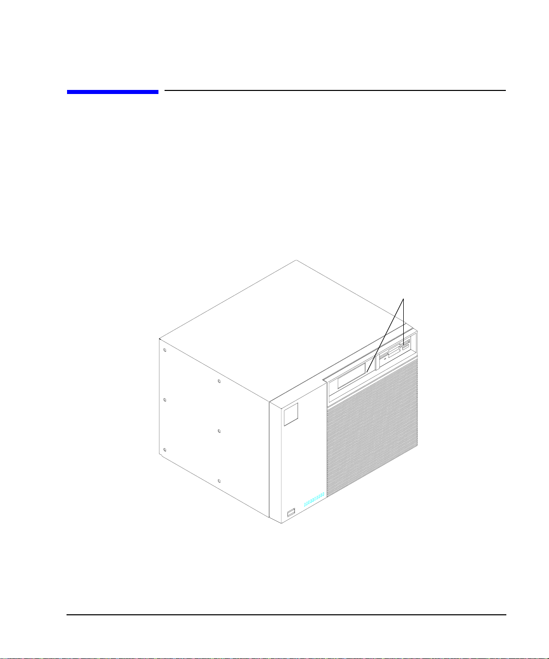
The Model 748 Ruggedized Workstation
The Model 748 ruggedized workstation provides a VMEbus card cage for a
wide variety of VME and PCI or EISA cards. In combi nation with the Model
743 or Model 744 board computer as the system contr oller , the Model 748 is
exceptionally flexible and responsive, being based on Hewlett-Packard’s
PA-RISC technology. Figure 1-1, Figure 1-2, and Figure 1-3 show a front
view of the Model 748, a rear view, and the front panel of the board computer.
.
Removable Medi a Devices
(front facing)
Figure 1-1 Model 748 Fron t View
1-3
Page 20
Product Description
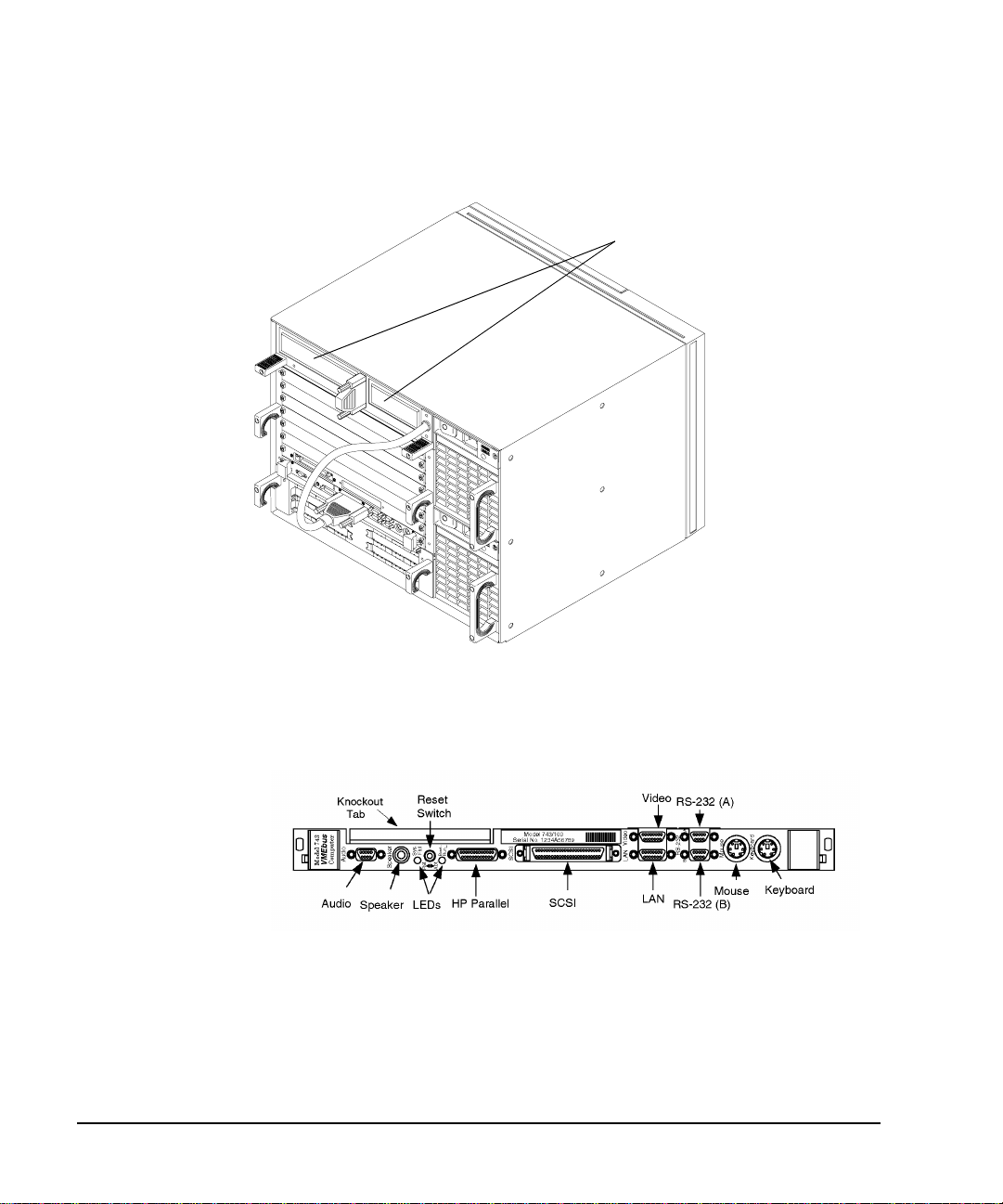
s
The Model 748 Ruggedized Workstation
Removable Medi a Device
(rear facing)
Figure 1-2 Model 748 Rear View
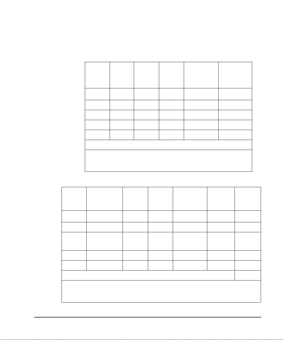
Figure 1-3 Board Computer Front Panel
1-4
Page 21

Product Description
Features
The Model 748 has the following general features:
• Two-slot 6U VME configuration for the processor and its options
• Six available 6U VME slots for user installed devices
• Input/Output (processor dependent):
On-Board gr aphics
RS-232C (2)
AUI (LAN)
PMC option cards (through optional PMC bridge and expansion
boards)
HP parallel
Features
Audio I/O, CD quality
Speaker port
Single-Ended (SE) SCSI
PS/2 keyboard and mouse; mini-DIN connector
HP-HIL (only in systems with an EISA tray)
• Mass s torage trays for up to four SE SCSI de vices, with up to two forward
or rear facing removable media devices
• Option board trays for up to four user installed devices,
PCI tray, or
EISA tray
• Two 350 Watt power supplies
1-5
Page 22

Product Description
Model 748 Physical Dimensions and Power Requirements
Model 748 Physical Dimensions and Power Requirements
• Height: 323.85 mm (12.75 in.)
• Width: 425.45 mm (16.75 in.)
• Depth: 419.1 mm (16.5 in.)
• Power: fully loaded, 90 A @120V ac
NOTE: Power requirements depend on the RAM, graphics, and SCSI hardware.
VME cards, and PCI/EISA card configuration as well as the software being
run. For example, each additional RAM card on the Model 743 board
computer adds .2 amps to the +5 Vdc requirement. For additional power
required by your VME and PCI/EISA card configuration, please see the
hardware specifications in your board computer service manuals.
1-6
Page 23

Board Computer Configurations
Memory , interface, gr aphics, and opera ting system confi gurations dep end on
the processor you selected when ordering your Model 748. Please refer to
the owner’s guide for your processor for memory configuration details.
Conversion Cables
The high-density I/O connectors for the board computers require conversions to standard cabling. These cables are 75 cm (30 in.) long. See Table 11 for details.
Table 1-1 Conversions to Standard Cabling
Product Description
Board Computer Configurations
Cable Number Description
HP A4300A
HP A4301A
HP A4302A
HP A4303A
HP A4304A
HP A4305A
HP A4223A
HP A4167A
HP Parallel: High Density 25-pin to standard 25-pin (female)
RS-232C: High Density 9-pin to standard 9-pin (male)
Audio: High De nsity 9-pin to bare w i res
LAN: High Density 15-pin to 15-pin AUI
Video for Model 743: High Density 15-pin to standard 15-pin (female)
Video for Model 743/744 with EVC monitors: High Density 15-pin to EVC
35-pin connector (female)
Video for Model 744: High Density 15-pin to standard 15-pin (female)
Video for GSC card: Std. 15-pin to EVC 35-pin connector (female)
In addition, standard cables are also available and may be required.
1-7
Page 24

Product Description
Conversion Cables
1-8
Page 25

2
Power Budget
2-1
Page 26

Power Budget
This chapter discusses the power budgeting for the Model 748 workstation.
2-2
Page 27

Power Budget
Power Budgeting
Power Budgeting
If your workstation’s application requires several accessory cards and mass
storage devices, power budgeting may be requ ired. Power bu dgeting e nsures
that the power nee d ed for the following in ter n a l d evices does not exceed the
power available:
• Mass storage devices
• Model 743 and Model 744 VMEbus Board Computer(s)
• Standard internal printed ci rcuit boards
• VME, PCI, and EISA accessory cards
The Model 748 ruggedized workstation uses two power supplies. Each
power supply provides voltages to the workstation's modules and accessory
card slots as listed in Table 2-6 and Table 2-7.
These tables are also worksheets to use in determining your power budget.
You may photocopy these tables as needed.
To determine the workstation’s power needs, follow these instructions:
1 Determine the board computer’s cu rrent requirem ents from the Co mputer
Current Requirements Worksheet (Table 2-3 or Table 2-4).
2 To determine the maximum current usage of the Model 744 memory
cards, either use Fi gure 2-1 and Table 2 -1 (for Model 744/132 L) or Tabl e
2-2 (for Model 744/165L). You must work with the worst case power
draw to correctly determine power usage. Determine worst case power
draw by examining active memor y bank confi guration s, using the following steps:
a Examine your memory card configuration, not ing which size card is i n
each memory slot.
b The worst case active memory bank configuration depends on the slot position of the
memory cards, and the size of the cards. The 32 MB memory card has two banks per
card, and th e 16, 64,1 28, and 25 6 MB cards e ach have o nly one memory ba nk per car d.
• When 32 MB cards are used as a pair in memory slots 2 and 3 they can use three
memory banks concurrently.
• When used as a pair in slots 0, 1, or 2, the 32 MB cards can have two active mem-
2-3
Page 28

Power Budget
Power Budgeting
ory banks.
• The 16, 64, 128, and 256 MB cards each have only one memory bank that is active
at any one time.
The worst case power draw is when your system has two 32MB cards in slots 2 and 3
(these banks would be considered active, all other memory cards/banks would be
considered inactive). The next worst case is a 256 MB card in any sl ot (all other
memory cards in the system would be inactive), followed by a 64 MB card in any slot
(all other memory cards in the system would be inactive), followed by two 32 MB
cards in slots 0, 1, or 2 (all other memory cards in the system would be inactive), followed by a 128 MB card in any slot, and finally a 16 MB card in any slot (all other
memory cards in the system would be in active).
c Inactive memory banks are those ba nks on cards in your conf iguration
in addition to the worst case a ctive memory banks . They must a lso be
added to the calculation.
d Fill in the information in Table 2-1 or Table 2-2.
Slot 3
Slot 2
Slot 1
Slot 0
Memory Slots
Figure 2-1 Model 744 Memory Slots
2-4
Model 744 Board Computer
Page 29
Power Budgeting
Table 2-1 Model 744/132L Memory Card Current Usage Worksheet
Power Budget
Memory
Card
Size
2
32 MB
First
Active
Bank
Second
Active
1
Bank
Third
Active
Bank
Inactive
Banks
1.15 A 1.15 A 1.15 A 0.05A x ___ __ _______
64 MB 2.6 A N/A N/A 0.1 A x ___ _________
128 MB 1.45A N/A N/A 0.07 A x ___ _________
16 MB 1.15 A N/A N/A 0.05A x ___ _________
256 MB 2.90 A N/A N/A 0.14 A x ___ _________
Total _________
1
Choose the worst case active bank(s) for your calculation.
2
Slot positions and amou nt of 32 MB car d s deter m in e the nu mb e r of acti ve ban k s.
Table 2-2 Model 744/165L Memory Card Current Usage Worksheet
Memory
Card
Size
2
32 MB
First Active
1
Bank
0.53 A (+12V) 0.53 A 0.53 A 0.023A x ___ ________
Second
Active
Bank
Third
Active
Bank
Inactive
Banks
Totals
(+12V)
Totals
(+5V)
Totals
(+5V)
64 MB 1.2 A (+12 V) N/A N/A 0.05 A x ___ ________
128 and
1.45 A (+5V) N/A N/A 0.07 A x ___ ________
256 MB
16 MB 0.53 A (+1 2V) N/A N/A 0.023A x ___ ________
256 MB 2.90 A (+5V) N/A N/A 0.14 A ______
Totals ________ ________
1
Choose the worst case active bank(s) for your calculation.
2
Slot positions and am ount of 32 MB cards deter mine the number of act ive banks.
2-5
Page 30

Power Budget
Power Budgeting
3 Write in the board computer’s concurrent requir ements in the line provid -
ed for VME slots 1 and 2 in the Lower Power Supply Worksheet (Table
2-7).
4 Determine each device’s current requirements from the Internal Device
Requirements table and the VME accessory card’s specifications sheet
(Table 2-5).
5 Write in each device’s current requirements i n the spac es provide d in the
Upper or Lower Power Supply current budgeting worksheets (Table 2-6
and Table 2-7).
6 Total each column in both workshe ets, then writ e the total in the Total
Current Required line.
7 If either worksheet has a column whose current totals exceed the maxi-
mum available for that c olumn’s volta ge, yo u must re duce th e number o f
devices to lower the total current being drawn at tha t voltage. You may be
able to relocate VME accessory cards be twe en the upper eight and lower
two slots to reduce the power required from either power supply.
2-6
Page 31

Table 2-3 Model 744 Current Requirements Worksheet
Power Budget
Power Budgeting
Each Model 744 Board Computer
If 132 MHz, current for +5V dc is 4.7A
If 165 MHz, current for +5V dc is 6.3A
+5V dc
Amps
1
______
RAM cards (see Table 2-1 or Table 2-2)
Graphics subsystems
2
x 0.9A each =
+12V dc
Amps
-12V dc
Amps
0.1A 0.1A
________
FWD SCSI GSC card x 0.7A each =
HCRX graphics board 2.0A _
PMC bridge adapter 0.6A
PMC cards on bridge adapter 3
________ ________
Totals for Model 744 board computer ________ ________
1. Does not include on-board gra phi c s, if i nstalled.
2. On-board graphics an d gra phics accessory cards are eac h sepa rate graphics subsystems .
3. PMC cards may also draw +3.3 curren t that is provided through the +5 on the bridg e adapter.
The +3.3 current FOR ALL PMC CARDS ON THE BRIDGE ADAPTER AND EXPANSION
ADAPTER (do not include other expansion adapter currents) must be entered into the +5 column
after multiplying the +3.3 current by .75 to convert to the actual +5 c urrent draw.
2-7
Page 32

Power Budget
Power Budgeting
Table 2-4 Model 743 Current Requirements Worksheet
Each Model 743 Board Computer
If 64 MHz, current for +5V dc is 6.1A
1
If 100 MHz, current for +5V dc is 7.5A
RAM cards x 0.2A each =
Graphics subsystems 2 x 0.7A each =
+5V dc
Amps
+12V dc
Amps
0.1A
-12V dc
Amps
0.1A
FWD SCSI GSC card x 0.7A each =
HCRX graphics board 2.0A
PMC bridge adapter 0.6A
PMC cards on bridge adapter 3
_________ _________
Totals for Model 743 board computer _________ _________
1. Does not include on-board gra phi cs, if installed.
2. On-board graphics an d gra phics accessory cards are eac h sepa rate graphics subsystems .
3. PMC cards may also draw +3.3 curren t that is provided through the +5 on the bridg e adapter.
The +3.3 current FOR ALL PMC CARDS ON THE BRIDGE ADAPTER AND EXPANSION
ADAPTER (do not include other expansion adapter currents) must be entered into the +5 column
after multiplying the +3.3 current by .75 to convert to the actual +5 c urrent draw.
2-8
Page 33

Table 2-5 summarizes the current requirements for the internal devices.
Table 2-5 Internal Device Current Requirements
Power Budget
Power Budgeting
Device
Internal mass storage devices:
CD-ROM drive 1.6 A 1.8 A
DDS tape drive 1.0 A 0.8 A
Flexible disk drive 0.8 A
1 GB SE hard drive 1.2 A 1.8 A
2 GB FWD hard drive 1.1A 0.9 A
2 GB SE hard drive 1.0 A 0.9 A
4 GB FWD hard drive 1.1 A 1.0 A
4 GB SE hard drive 1.0 A 1.0 A
9 GB FWD hard drive 1.2 A 0.9 A
Hewlett-Packard EISA Cards:
HP 25525A SCSI DIFF 3.1 A 0.05 A
HP 25525B EISA SCSI 3.06 A 5 mA 5 mA
HP 25560A HPIB 3.1 A
+5.1V dc
Amps
+12V dc
Amps
-12V dc
Amps
HP 25567A LAN 3.4 A 0.04 A
HP J2156A FDDI 2.0 A 0.09 A 0.05 A
HP J2159A X.25 PSI 3.4 A 0.04 A
HP J2165A LAN 2.1 A
HP J2645AA VG Any LAN 0.3 A
HP J2802B ATM
2-9
Page 34

Power Budget
Power Budgeting
Table 2-6 Upper Power Supply Current Budgeting Worksheet
Location Device
VME Slot 8
VME Slot 7
VME Slot 6
VME Slot 5
VME Slot4
VME Slot 3
or PMC cards
in Expansion
1
Adapter
1. +3.3 current must be entered into Table 2-3 or Table 2-4
Total Current
Required:
Maximum Available:
+5V dc
Amps
34.0A
+12V dc
Amps
8.0A
-12V dc
Amps
1.5A
CAUTION: If you upgrade your Model 748 ruggedized workstation, adding more: RAM
cards, mass storage devices, GSC, VME, EISA, PCI, or PMC accessory
cards, you must recompute the power budget to ensur e the new configu ration
will be within the available current each power supply can provide.
2-10
Page 35

Power Budget
Power Budgeting
NOTE: The PCI tray provides power for option cards from both a +5 Vdc source and a +3.3 Vdc
source. Cards may use either or both power sources, up to 25W per slot. However, the
+3.3 V dc source is limited to 39.8 W com bined for slots 1 and 2, an d 39.8 W combined
for slots 3 and 4. For example, if the card in slot 1 draws 25 W at +3.3 V dc, only 14.8
W at +3.3 V dc is available to a card in slot 2. The limits of + 5 Vdc is 25 W per slot.
2-11
Page 36

Power Budget
Power Budgeting
Table 2-7 Lower Power Supply Current Budgeting Worksheet
Location Device
Mass Storage
+5V dc
Amps
+12V dc
Amps
-12V dc
Amps
-5.2V dc
Amps
Device 1
Mass Storage
Device 2
Mass Storage
Device 3
Mass Storage
Device 4
VME Slot 2
and
VME Slot 1
Model 743/744
Board
Computer
_______
EISA/PCI Slot 1
EISA/PCI Slot 2
EISA/PCI Slot 3
EISA/PCI Slot 4
2-12
Total Current Required:
Maximum Available:
33.0A
8.0A
1.5A
1.0A
Page 37

3
VME Card Installation
3-1
Page 38

VME Card Installation
This chapter describes installing a VME card into the Model 748 workstation.
The major sections within this chapter are:
• VME Overview
• VME Installation Outline
• Installing VME Accessory Card Hardware
3-2
Page 39

VME Card Installation
VME Overview
VME Overview
VME (Versa Module Eurocard) cards use a VME bus protocol which all ows
various kinds of microprocessors to communicate with one another. The
protocol is microprocessor independent, implements a reliable mechanical
standard, and allows independent vendors to build compatible products.
One feature of VME is that multiple CPUs can be configured into the same
VME backplane. Each one function s as a complet ely separa te proce sso r, but
they all must be able to access address space that may or may not exist on
the local computer board. The address space that one CPU needs to access
may be on a separate memory card or on an entirely different CPU board.
The VME standard allows two board sizes:
• Half height or 3U boards. These boards connect to the VME backplane
utilizing only one of the two backplane connectors.
• Full heigh t or 6U boards. These boards connect to the VME backplan e utilizing both of the backplane connectors.
3U size boards are often pr ovided with ei ther 3U size or 6U si ze cover pl ates
allowing them to be placed in either a half height or full height chassis.
The Model 748 provides eight full-height VME slots. The VME System
Controller occupies slots 1 and 2, l eavin g slot s 3 thr ough 8 av ailab le for us e.
In the backplane, slot 3 is the lowermost slot and slot 8 is the uppermost.
The vendor of your VME card should have provided installation configuration settings for the car d, for your partic ular applic ation. These usua lly allow
the card to be installed in one of several default locations.
All VME cards require kernel drivers. The HP-UX kernel provides a set of
services in the fileset VME-SERV which allows the user-provided kernel
drivers access to VME space. You can use SAM to ensure that the vme2
driver is in your HP-UX kernel.
Your vendor should have provided you with the necessary files and instructions for linking the dr iver f or your ca rd into the HP-UX kernel . Documen tation for creating these drivers for HP-UX 9.0x is contained in the HP-UX
3-3
Page 40

VME Card Installation
VME Overview
9.05 VME Configuration and Driver Development Guide (Part Number
A2636 90020). Documentation for creating these drivers for HP-UX 10.x is
contained in the VME Services for HP-UX 10 (Part Number A4412 90021).
CAUTION: If you need to remove the VME tray module from the cardcage, the PCI or
EISA tray module must be removed first.
Following is an outline of the steps for installing VME Cards. For complete
instructions for installing VME cards and configuring VME resources,
please refer to the HP-UX 9.05 VME Configuration and Driver Devel opment
Guide (Part Number A2636-90020) or VME Services for HP-UX 10 (Part
Number A4412-90022). You will need the information in these guides to
configure VME resources.
CAUTION: Please note that when you are installing any VME card into any VME card
cage, DO NOT let the card han g by its own weigh t whil e you s lide it i nto t he
card cage. For horizontally mounted cards, you MUST lift the card slightly
so that the card clea rs cards or bezel s mounted in lower sl ots, in order to avoi d
damage to components on the underside of the card. For vertically mounted
cards, you MUST in sert the c ard carefull y to avoid c ontacting car ds or bezels
to the right or left.
3-4
For more information on the VME specification for this observation,
please refer to The VMEbus Specification, ANSI/IEEE STD-1014-
1987 IEC 821 & 297, Section 7.10.
Page 41

VME Card Installation
VME Installation Outline
VME Installation Outline
VMEbus physical slot numbers are: 1 to 8
• The syste m cont roll er boa rd comput er (Model 74 3/7 44) occ upies the bottom two slots (slots 1 and 2).
• Slots 3 th rough 8 are t he accessi ble slots in the VME module. The se slots
are numbered on the backplane of the VME module.
There are no switches or jumpers on the VME backplane to set.
The following list is a brief outline of the installation procedure adding
devices to HP-UX. For more detailed information please see the VME Ser-
vices for HP-UX 10 manual. Follow these general steps:
1 First, add the new configuration information in the vme.CFG text file.
2 Run the vme_config utility to configure VME resources.
3 Make device files for the card and driver with mknod.
4 Add the driver to the dfile (HP-UX 9.x only).
5 Compile the driver if necessary.
6 Update various files to include information about the driver.
7 Generate a new kernel containing the driver.
8 Build and inst all the new ke rnel.
9 Make a backup copy of the kernel.
10 Shut down and turn off the system.
11 Plug in the card(s) (according to the procedure in “Installing VME Ac-
cessory Card Hardware”).
12 Turn on the system.
3-5
Page 42

VME Card Installation
Installing VME Accessory Card Hardware
Installing VME Accessory Card Hardware
You’ll need these tools to access the VME cards:
• Small flat-tipped screwdriver
• Medium flat-tipped screwdriver
• Static-free work space
Installation Procedures
CAUTION: When removing the VME module, the PCI/EISA module must be removed
first. When reinstalling, replace the VM E module first.
1 Stop any application programs, and then shut down the SPU.
2 Turn the VMEbus chassis off, and unplug the power cords.
3 Using Figure 3-1 as a guide, loosen the captive screw on each end of the
slot covers where you will install VME card (s ), and then remove th e cov ers.
Figure 3-1 Installing a VME Card
3-6
Page 43

VME Card Installation
Installing VME Accessory Card Hardware
4 Refer to your VME card installation manual, and then set any hardware
configurations that may be required for your application.
5 Slide the VME accessory card into the slot, and then tighten its screws.
6 Plug in the power cords, and then turn on your workstation and boot the
operating system.
For More Information
For detailed procedures for configuring VME cards and associated drivers,
see HP-UX 9.05 VME Configuration and Driver Development Guide or
VME Services for HP-UX 10.
3-7
Page 44

VME Card Installation
Installing VME Accessory Card Hardware
3-8
Page 45

4
EISA Card Installation
4-1
Page 46

EISA Card Installation
This chapter describes installing an EISA card in the Model 748 workstation.
The major sections within this chapter are:
• EISA Accessory Card Configuration Files
• Hardware Installation
4-2
Page 47

EISA Card Installation
EISA Accessory Card Configuration Files
EISA Accessory Card Configuration Files
Four EISA slots are available in the Model 748. The man page
eisa_config(1M) has current information on installing your EISA card(s) on
HP-UX using the eisa_config utility.
The configuration for EISA cards is determined when the system reads a file
in the following directory:
/etc/eisa
This directory contai ns a numbe r of file s des cribing EI SA ident itie s and con figurations for various systems. A file in this directory applies to your system and contains information as to how many slots are available and how
they are identified. Your system will give you an error message should you
attempt to address a card having a numerical ID that exceeds the number of
EISA slots available on your system.
4-3
Page 48

EISA Card Installation
Hardware Installation
Hardware Installation
Tools Required
You’ll need the following items to access the EISA cards in the Model 748
• Medium flat-tipped screwdriver.
• Static-free work area.
Procedure
1 Stop any application programs, and then shut down your workstation.
2 Turn the workstation off, and unplug the power cord(s).
3 Using a flat-tipped screwdriver, unscrew the captive screws inside the
EISA module handles five to seven turns (until each screw pops out).
4-4
4 Grasp the EISA module handles and pull the EISA module ou t of the chas-
sis, as shown in Figure 4-1.
Page 49

Slot 1
Slot 2
EISA Card Installation
Hardware Installation
Screws
Figure 4-1 Removing the EISA Tray
5 Note that the slots are numbered from 1 to 4.
Cards for slots 1 a nd 2 ar e ins tall ed compone nt si de down; cards for slots
3 and 4 are installed component side up.
Loosen the card retai ner captive screw (see Fi gure 4-2) for the ap propriate
slot, and then remove the card retainer.
Slot 4
Slot 3
4-5
Page 50

EISA Card Installation
Hardware Installation
Card Retainer Captive Screw
Figure 4-2 Card Retainer Screw
6 Remove the slot cover plate by pulling it out of the EISA module.
7 Refer to your EISA card installation manual, and then set any configura-
tions that may be required for your application.
8 Install the EISA card in the s lot. Make sure i ts conne ctor is well seat ed in
the EISA backplane.
NOTE: Note that, due to clearance problems with the cable connectors, EISA HP-IB
cards cannot be installed vertically adjacent to each other. These should be
installed on opposi te sides. If you find it necess ary to instal l an EISA HP-IB car d
directly over anot her on e, you wi ll ha ve to use low-pr ofil e conne ctors furni shed
by other manufacturers.
9 Replace the EISA card retainer, and then tighten its screw.
10 Slide the EISA module back into the VMEbus chassis, as sho wn in Figure
4-3, and then tighten its handle screws.
4-6
Page 51

EISA Card Installation
Hardware Installation
Figure 4-3 Sliding the EISA Module Back into the VMEbus Chassis
11 Plug in the power cord, and then turn on the power for the VMEbus chas-
sis and boot the operating system.
12 Verify the installation by running the Support Tools Manager, as de-
scribed in your board computer’s owner’s guide.
For More Information
Refer to Installing Peripherals and your EISA installation guide for information on the EISA accessory card application, loading the software, and
running it.
4-7
Page 52

EISA Card Installation
Hardware Installation
4-8
Page 53

5
PCI Card Installation
5-1
Page 54

PCI Card In stallation
This chapter describes installing a PCI card in the Model 748 workstation’s
PCI tray.
The PCI tray accommodates up to four user installed PCI cards. The PCI
cards must be standard +5 Vdc bus signalling cards.
Your system must be running version 10.20 or la ter of t he HP- U X opera ti ng
system.
NOTE: The PCI module does not support HIL devices.
5-2
Page 55

PCI Card Installation
Hardware Installation
Hardware Installation
1 Stop any application programs, then shut down your workstation.
2 Turn the workstation off, and unplug the power cord(s).
WARNING: To avoid electrical shock, make sure you unplug the power cable from the wall
outlet and the system unit before proceeding any further.
CAUTION: The internal components of your workstation are susceptible to mechanical
and electrostatic shock. To prevent such damage from occurring, observe
the following precautions during the installation procedure.
• Stand on a static-free mat
• Wear a static-grounding wrist strap to ensure that any accumulated
electrostatic charge discharges from your body to ground. Attach the
static-grounding wr is t strap by following th e i nst ructions on the pack age that contains the strap. Be sure to attach one end of the strap to the
system chassis.
• Handle workstation and upgrade kit components carefully to prevent
damage from mechanical shock.
5-3
Page 56

Slot 1
Slot 2
PCI Card In stallation
Hardware Installation
3 Using a flat-tipped screwdriver, unscrew the captive screws inside the PCI
module handles five to seven turns (until each screw pops out).
4 Grasp the PCI module handles and pull the PCI module out of the cha ssis,
as shown in Figure 5-1.
Screws
Figure 5-1 Removing the PCI Module
5 Note that the slots are numbered on the face of the tray from 1 to 4.
5-4
Slot 4
Slot 3
Page 57

PCI Card Installation
Hardware Installation
NOTICES: This PCI tray only supports option cards with +5 Vdc bus signalling.
If your workstation application requires several accessory cards and mass
storage devices, power budgeting may be required. This ensures the power
needed for these internal devices does not exceed the power available in
the system.
The PCI tray provides power for option cards from both a +3.3 Vdc source
and a +5 Vdc source. Cards may use either or both power sources, up to
25W per slot. However, the +3.3 V dc source is limited to 39.8 W
combined for slots 1 and 2, and 39.8 W combined for slots 3 and 4. For
example, if the card in slot 1 draws 25 W at +3.3 V dc, only 14.8 W at
+3.3 V dc is available to a card in slot 2. The limits of + 5 Vdc is 25 W per
slot.
If you upgrade your system, adding more: RAM cards, mass storage
devices, or VME, or PCI accessory cards, you must recompute the power
budget to ensure the new configuration will be within the system’s
capability.
Refer to Chapter 2 for power budgeting.
Cards for slots 1 a nd 2 ar e ins tall ed compone nt si de down; cards for slots
3 and 4 are installed component side up.
Loosen the card retai ner captive screw (s ee Figure 5-2) for the ap propriate
slot, and then remove the card retainer, as shown in Figure 5-3.
Card Retainer Captive Screw
Figure 5-2 Card Retainer Captive Screw
5-5
Page 58

Card Retainer
Slot Cover Plate
PCI Card In stallation
Hardware Installation
Figure 5-3 Removing the Card Retainer and Slot Cover Plate
6 Remove the slot cover plate by pull ing it out o f the PCI module , as shown
in Figure 5-3.
7 Refer to your PCI card installation manual, and set any configuration
switches or jumpers that may be required for your application.
5-6
Page 59

PCI Card Installation
Hardware Installation
8 Install the PCI card in the slot, as sho wn in Figur e 5-4. M ake sur e its con -
nector is completely seated in the PCI backplane.
Figure 5-4 Installing a PCI Option Card
9 Replace the PCI card retainer, and then tighten its screw
5-7
Page 60

PCI Card In stallation
Hardware Installation
10 Slide the PCI module into the VMEbus chassis, as shown in Figure 5-5,
and tighten its handle screws.
Figure 5-5 Installing the PCI Module into the VMEbus Chassis
11 Plug in the power cord, and then turn on the power for the VMEbus chas-
sis and boot the operating system.
12 Log in as root and us e the SAM utility to configure the HP-UX kernel for
PCI support.
13 When SAM has started, choose the Kernel Configuration ->
menu.
14 From the Kernel Configuration menu, choose Drivers
5-8
Page 61

PCI Card Installation
Hardware Installation
15 From the Drivers menu, select
16 Go to the
Actions
menu and select
GSCtoPCI Driver.
Create a New Kernel.
17 When the new kernel is built, SAM asks if you want to move the kernel
into place and reboot. Choose Yes.
The system reboots with the PCI driver loaded.
For More Information
Refer to Installing Peripherals and your PCI card’s installation guide for
information on the PCI a ccessory c ard applic ation, loa ding the sof tware, and
running it.
5-9
Page 62

PCI Card In stallation
Hardware Installation
5-10
Page 63

6
Installing and Configuring Mass Storage Devices
6-1
Page 64

Installing and Configuring Mass Storage Devices
This chapter describes installing the mass storage drives in your Model 748
workstation.
The major sections within this chapter are:
• Hardware Installa tion for Drives
• Finding the Status of Existing SCSI Bus Addresses
• Installing Mass Storage Devices
• Configuring for a Hard Disk Drive
6-2
Page 65

Installing and Configuring Mass Storage Devices
Hardware Installation for Drives
The following products are supported for mass storage in the Model 748i.
The mass storage module can hold up to four drives. All products include
installation hardware for either a 3.5-in. or 5.25-in. mass storage bay:
Table 6-1 Supported Mass Storage Products
Description
4 GB Single-Ended Disk
2 GB Single-Ended Disk
1 GB Single-Ended Disk (with Model 743 processor only)
2 GB Fast Wide Differential Disk (requires optional tray)
Hardware Installation for Drives
4 GB Fast Wide Differential Disk (requires optional tray)
9 GB Fast Wide Differential Disk (requires optional tray)
3.5 in., DDS Tape Drive
5.25 in., CD-ROM Drive
3.5 in., 1.4 MB flexible disk drive
Tools for Installation
Before you start to install a new drive, make sure you have the following
tools:
Medium flat-tipped screwdriver.
#1 Pozidriv driver.
Static-free work area.
6-3
Page 66

Installing and Configuring Mass Storage Devices
Hardware Installation for Drives
Module Orientations
The Model 748i uses two mas s storage modul e holds u p to four si ngle-ended
SCSI devices.
Removable media drives can be fitted to be accessible from either the front
or the rear of the Model 748 chassis. See Figure 6-1 for some typical locations.
The mass storage module it self can onl y be re moved f rom the rear ( I/O si de)
of the chassis. If your system is r ack-mounte d, front si de out, try to space t he
rack with enough room to remove the module from the rear.
Figure 6-1 Mass Storage Module: Typical Device Positions
6-4
Page 67

Installing and Configuring Mass Storage Devices
Finding the Status of Existing SCSI Bus Addresses
Finding the Status of Existing SCSI Bus Addresses
Before you install a new SCSI drive, to ensure that the SCSI bus address of
your device is currentl y unused, you ca n use SAM, or you can use the ioscan
tool to help deter mine which de vices ar e current ly connec ted. Of course , this
is especially necessary for a system in which devices have previously been
installed. To determine the currently connected SCSI bus IDs, enter the following command line:
/etc/iosc an -fb (for HP-UX 9.x)
/usr/sbin/ioscan -f (for HP-UX 10.x)
The result will be a display of information, similar to the following:
Class H/W Path Driver H/W Status S/W Status Description
==============================================================
...
disk 2.0.1.2.0 scsi ok(0x5800101) ok TOSHIBA CD-ROM
tape_drive 2.0.1.3.0 scsitape ok(0x1800202) ok HP HP35450A
disk 2.0.1.6.0 scsi ok(0x101) ok MICROP 1528
...
For example, the SCSI bus address for the “MICROP” disk device is in the
fourth column of its hardware addr ess as “6” (2.0.1.6.0). SAM will help you
determine an address for the device when you do the installation.
Use the following table to write down the current SCSI bus addresses:
Current SCSI Addresses and Devices
SCSI Address: Device:
SCSI Address: Device:
SCSI Address: Device:
SCSI Address: Device:
6-5
Page 68

Installing and Configuring Mass Storage Devices
Installing Mass Storage Devices
Installing Mass Storage Devices
Removing the Mass Storage Module
1 Determine what SCSI bus addresses a re in use by following th e procedure
in the previ ous section. Be sure to write down this information.
2 Shut down your system by typing shutdown -h 0 Enter
and responding
to the confirmation message.
3 Turn off the power to the Model 748i VMEbus chassis. 4 Unplug the power cables to the Model 748i. 5 Unplug the external SCSI cable from the board computer. 6 Inside each handle for the mass storage module is a slotte d captive screw.
Unscrew each of the two screws about 7 turns (until it pops out).
7 Pull the mass storage module all the way out and place it on a clean, se-
cure, and static-free surface.
Removing a Device from the Mass Storage Module
CAUTION: Hard disk driv es are vulnerab le to physica l shock. Dr opping a h ar d disk drive
from even a small height will damage its heads and platters. Always handle
hard disk drives with extreme caution. Do not place a hard disk drive upside
down on any surface.
Follow these steps to remove a drive.
1 Unplug power and SCSI cables for the drive.
2 Loosen the screws for that drive underneath the mass storage module.
6-6
3 Slide the drive back in its mounting keyhole slots about 12 mm (0.5-in.)
to free the screws. Then lift the drive up and out of the module.
4 Repeat this procedure, as needed, if you are r emovi ng additional devices.
Page 69

Installing and Configuring Mass Storage Devices
Installing Mass Storage Devices
Installing a Device in the Mass Storage Module
1 Remove the new device from its shipping box
2 Ensure that the hardware SCSI bus address selected on the device is not
already us ed by the syst em.
3 In the case of a removable media de vice (flexible disk or DDS tape) note
any special requirements for bezel installation.
NOTE: Installing a floppy disk drive or a DDS drive requires a large bezel for the
upper right or lower left position.
4 Find the hardware in the install ation kit. This includes four screws with
shoulder washers which you should now insert loosely into the appropriate holes in the lower surface of the device.
5 If this is a removable media dev ice, do the follow ing:
a Remove the appropriate fill-in panel from the access side of the Model
748i by removing the attaching screw.
b Pry off the small front bezel in the removable media device
c Snap on the new, larger bezel.
6 Find the location on the mass-storage module where you want to mount
the device.
7 Invert the device and fit the loosely-fitted screw heads into the large end
of the appropriate ke yhole slot, at that locatio n (See Figure 6- 1 for typica l
locations and Figure 6-2 for installation.)
6-7
Page 70

Installing and Configuring Mass Storage Devices
Installing Mass Storage Devices
Figure 6-2 Device Installation in the Mass Storage Module
8 Tighten the mounting screws.
9 Replace the individual SCSI and power connectors.
10 Replace the mass-storage module in the Model 748i.
11 Tighten the captive screws for the mass storage module.
12 Reconnect the external SCSI cable.
13 Reconnect the power cables.
14 Turn on the Model 748i and stop the boot pr ocess at the prompt by press -
ing Esc
6-8
.
Page 71

Installing and Configuring Mass Storage Devices
Installing Mass Storage Devices
15 Press 6 followed by Enter to loo k at the HARDWARE INFORMATION
screen.
16 Ensure that the new device is listed in
HARDWARE INFORMATION.
6-9
Page 72

Installing and Configuring Mass Storage Devices
Configuring for a Hard Disk Drive
Configuring for a Hard Disk Drive
Hard disk drive upgrades can be inst alle d to acc ommodate l ocal f ile sy stems
and swap space on your workstation.
Software Installation of the Hard Disk Drive Upgrade
After hardware installation has been completed, you’ll need to ensure that
your operating system is prepared to exchange data with the device. This
section provides instructions for manually configuring HP-UX to communicate with hard di sk drive upgrades, in or der to use the disk s for ma ss storage
and/or swap space. Note that your HP disk is pre-formatted.
CAUTION: Although the device is well-protected from physical shock when installed in
the workstation, it is very easily damaged when separate. Avoid dropping or
striking a device.
6-10
The factory-set SCSI bus address for the disk drive For an upgrade disk
drive: SCSI bus address: 6
This SCSI address assumes usage of the disk as
root. Although the config-
uration jumpers in the back of the drive are factory-installed and should not
require reconfiguri ng, it i s possi ble th at the SCSI bus addr ess jumpe rs for an
upgrade may be shipped with different settings. Therefore, please see the
Installation Chapters| for the drive and the procedure for resetting jumpers,
should it be necessary.
The following list outlines the software procedures you’ll find in this section for installing the hard disk drive as a file system disk:
• Verify t hat you have an unused device f ile with the correct se lect code and
bus address for your device. (Use SAM).
•Use SAM to:
Install a disk on HP-UX.
Build a file system on the disk (done automatically by SAM).
Mount the disk so that you can access it as a file system.
Page 73

Installing and Configuring Mass Storage Devices
NOTE: SAM does not support the following:
• Changing t he hardware a ddress of a disk drive containi ng the root f ile
system.
• Changing the hardware address of a disk array.
• Changing the hardware address of a disk that is part of software disk
striping.
After hardware installation has been completed, you’ll need to ensure that
your operating system is prepared to exchange data with the device. This
section provides instructions for doing this.
1 Run SAM by typing:
/usr/bin/sam (for HP-UX 9.x)
/usr/sbin/sam (for HP-UX 10.x)
Configuring for a Hard Disk Drive
Pressing the f1
key gives you context-sensitive information for the object at
the location of the cursor.
2 Choose
Enter
3 Choose
Disks and File Systems (highlight and click on OK or press
).
CD-ROM, Floppy, and Hard Disks.
4 Choose the line identifying the type of new disk you have connected. In
the “Use” column, it will be designated as “unused”.
5 In the next screen, choose the line identifying the model of the n ew disk.
If the device you have connected does not appear on the list:
A Check your hardware connections, and make sure that the device is turned on.
B Click on the button
tions:
Have SAM rescan the system for the device. If you have connected the device after starting SAM, you should click on Yes. Otherwise, click on No.
Respond to the confirmation screen regarding whether the dev ice is connected and powered up.
Respond to the confirmation screen regarding whether additional device
drivers are needed. (Unless the kernel has, for some reason, had drivers re-
Device Missing
, and you will be given the following op-
6-11
Page 74

Installing and Configuring Mass Storage Devices
Configuring for a Hard Disk Drive
moved, the drivers needed for a hard disk should currently be in the kernel.)
You will be given an information screen suggesting things to try if the device
still cannot be found. If this is the case, you will need to consult the man ual
Peripheral Installation Guide.
After you choose the device, you will see a form giving three tasks:
1 Select a Disk to Add. (You have already done this).
Set Disk Usage and Options.
2
Modify Defaults.... (This task is optional).
3
Choose:
Set Disk Usage and Options.
1 On the form which appears, select how you want to use the disk (“File
System”, or other usage).
2 Click on OK when you have finished with this form.
3 A “Messages” Box appears, reporting the progress of th e task . Whe n the
task is finished, click on
OK.
4 Exit SAM. (SAM copies your original /etc/checklist to /etc/check-
list.old).
Testing Your Installation
A simple test to make certain that the drive ha s been installed correctly
(whether it is mounted or not) is to execute the command
diskinfo, using
the appropriate character device file name as the argument. For example:
diskinfo /dev/rdsk/c201d5s0
If the disk is installed correctly, diskinfo will display a listing of information
about it, such as the following:
6-12
Page 75

Installing and Configuring Mass Storage Devices
Configuring for a Hard Disk Drive
SCSI describe of /dev/rdsk/c201d5s0
vendor: Quantum
product id: XXXXXXX
type: direct access
size: 200000 Kbytes
bytes per sector: 512
After mounting a new disk on a directory, an ll listing of the directory
should give you at least one file or directory entry. For example:
total 1024
drwxr-xr-x 2 root root 8192 Aug 31 15:24 lost+found
6-13
Page 76

Installing and Configuring Mass Storage Devices
Configuring for a Hard Disk Drive
6-14
Page 77

7
Using Mass Storage Devices
7-1
Page 78

Using Mass Storage Devices
Using your CD-ROM Drive
Using your CD-ROM Drive
This section describe s how to us e your CD-ROM dri ve. It is d ivided into t he
following subsections:
• CD-ROM drive and CD-ROM media descriptions
• Operating the CD-ROM Drive
• Mounting and unmounting a CD-ROM disc
• Troubleshooting
NOTE: Be sure you read and understand the information on mounting and
unmounting CD-ROM discs before you begin using your CD-ROM disc
drive.
This chapter provides an overview of the optional CD-ROM drive and
media, and describes how to use the CD-ROM drive. We assume the CDROM drive is set to the factory default address of SCSI ID 2.
NOTE: Some procedures in this chapter require you to log in as root. If you cannot log
in as root, contact your system administrator.
7-2
Page 79

Using Mass Storage Devices
CD-ROM Drive and CD-ROM Media Descriptions
CD-ROM Drive and CD-ROM Media Descriptions
This section describes basic information needed for using the CD-ROM
drive and CD-ROM discs.
CD-ROM Drive
The CD-ROM drive is a random access read-only mass storage device that
uses removable CD-ROM discs. The drive supports the ISO 9660 and High
Sierra format standards. You can access information from the drive like any
other disk drive, except tha t you cannot write to the dri ve. The drive contai ns
a semiconductor laser for reading data optically, and includes an embedded
controller with a SCSI interface.
Controls and Features
Figure 7-1 shows and Table 7-1 describes the operating controls and features
of the CD-ROM drives.
Headset
Jack
Figure 7-1 CD-ROM Drive Controls and Features
Volume
Control
Thumbwheel
Indicator
Busy
Emergency
Eject Hole
Eject
Button
7-3
Page 80

Using Mass Storage Devices
CD-ROM Drive and CD-ROM Media Descriptions
Table 7-1 CD-ROM Controls and Features
Control/Feature Purpose
Headset Jack You can plug mini-headphones with a 3.5-mm diameter
miniature stereo plug into this jack.
Volume Control Use the volume control to adjust the audio output volume to
the headset jack.
Busy Indicator The Busy Indicator lights during a data access operation and
blinks during a data transfer. The indicator blinks initially
and then stays lit when there is one of the following:
• A defective disc
• A disc insertion error (for example, an upside-down disc)
• No disc present
Eject Button Press the Eject Button to open the Disc Tray and insert or
remove a disc. When the drive is in use, you must press the
eject button for more than one second to open the Disc Tray.
Emergency Eject By removing the Phillips type screw and inserting the end of
a paper clip, you can open the Disc Tray when the
workstation does not have power.
NOTE: The Volume Control, Headset Jack, and Audio Jack fea tures of t he CD-ROM
drive are supported through applications only.
CD-ROM Media
CD-ROM discs are 120 mm (4.7 in.) in diameter, and use one data surface
with a capacity of approximately 600 megabytes. The data surface contains
pits and flat spots arranged in a continuous spiral track, which is read at a
constant speed. You may access files and data stored on a CD-ROM disc,
but you may not write files or data to a CD-ROM disc.
CD-ROM data discs are identical to audio compact discs (CDs) except that
they store computer data and information.
7-4
Page 81

Using Mass Storage Devices
CD-ROM Drive and CD-ROM Media Descriptions
CAUTION: Handle CD-ROM discs by the edges only. Always be sure a CD-ROM disc
is either in the CD-ROM drive or its protective case when not in use. This will
lessen the chance of exposing the dis c surface to dus t. Over time, dust reduces
the reliability of the read h ead in the CD-ROM drive.
Caring for CD-ROM Discs
Observe the following guidelines to help prevent data loss and prolong the
life of your CD-ROM discs and drive:
• Use CD-ROM dis cs in a clean envir onment to preven t dust parti cles from
scratching disc surfaces.
• Store CD-ROM discs in a cool, dry place to prevent moisture and heat
damage.
• Don’t try to clean the surface of a CD-ROM disc with cleaning solvents,
as some cleaning solvents may damage the disc.
NOTE: You must mount the disc after loading it into the drive. Refer to the section
“Mounting and Unmounting a CD-ROM Disc,” later in this chapter, for
instructions about mounting a disc.
7-5
Page 82

Using Mass Storage Devices
Operating the CD-ROM Drive
Operating the CD-ROM Drive
This section describes how to perform tasks with your CD-ROM drive.
Loading and Unloading a CD-ROM in the Disc Tray
This subsection describes how to load or unload a CD-ROM disc in the CDROM drive.
Disc Tray Description
This CD-ROM is designed to be used in either the horizontal or vertical
position, dependin g on whe the r yo ur s y st em uni t i s ho ri zont al or vertical (in
the floor stand). T he disc t ray has f our disc holders th at hold the disc in place
when the CD-ROM drive is in the vertical position. When the drive is in the
horizontal positi on, the disc holders are not us ed and are held out of t he wa y
by four disc holder retainers. Figure 7-2 shows the CD-ROM disc tray, and
disc holders.
Figure 7-2 CD-ROM Disc Tray
7-6
Page 83

Using Mass Storage Devices
Operating the CD-ROM Drive
Loading a CD-ROM Disc
This CD-ROM drive has an automatic loading/ejecting feature. To load a
disc in the CD-ROM drive, follow these steps:
Figure 7-3 Placing a CD-ROM Disc in a Drive
1
Check that the workstation is powered on.
2 To open the disc tray, press and release the load/eject button on the CD-
ROM drive.
3 Be sure the disc holders are slid away from the disc.
4 Hold the disc by the edges with the label side up and place it in the disc
tray as shown in
5 To close the disc tray, push the front of the disc tray gently towards the
Figure 7-3.
drive until it closes by itself.
7-7
Page 84

Using Mass Storage Devices
Operating the CD-ROM Drive
Unloading a CD-ROM Disc
Perform the following steps to unload a disc from the CD-ROM drive:
Figure 7-4 Removing a CD-ROM Disc From a Drive
1 Press the eject button to eject the disc tray from the drive. If the drive is in use,
you must press the eject button for more than one second to eject the disc tray.
NOTE: You must unmount the disc before ejecting it from the drive. Refer to the
subsection, “Unmounting a CD-ROM Disc Using SAM,” for instructions on
unmounting a disc.
2 Wa it until the drive has fully ejected the disc tray, then remove the disc
from the tray as shown in
Figure 7-4. Be careful to touch only the edges of
the disc.
3 To close the Disc Tray, push the front of the disc tr ay gently towards the
drive until it closes by itself.
7-8
Page 85

Using Mass Storage Devices
Operating the CD-ROM Drive
Verifying the CD-ROM Drive Operation
To verify that your workstation can communicate with the CD-ROM drive,
follow these steps:
1 In a terminal window, enter the following command:
/etc/ioscan -d sdisk Enter (For HP-UX 9.x)
/usr/sbin/ioscan -d sdisk Enter
(For HP-UX 10.x)
After a few moments the ioscan utility lists all of the SCSI I/O devices it
could find. The list appears similar to the following:
H/W Path Class Description
============================================
bc
8 bc I/O Adapter
8/12 ext_bus GSC built-in Fast/Wide SCSI Interface
8/12.0 target
8/12.0.0 disk QUANTUM LPS1080WD
8/12.5 target
8/12.5.0 disk DEC DSP3210SW
8/12.6 target
8/12.6.0 disk DEC DSP3210SW
8/16 ba Core I/O Adapter
8/16/5 ext_bus Built-in SCSI
8/16/5.2 target
8/16/5.2.0 disk TOSHIBA CD-ROM XM-4101TA
8/16/5.4 target
8/16/5.4.0 disk SEAGATE ST3600N
8/16/5.6 target
8/16/5.6.0 disk MICROP 2112
10 bc I/O Adapter
10/12 ext_bus GSC add-on Fast/Wide SCSI Interface
10/12.4 target
10/12.4.0 disk SEAGATE ST31200W
7-9
Page 86

Using Mass Storage Devices
Operating the CD-ROM Drive
If ioscan does not see your CD-ROM drive it returns the following message:
ioscan: No hardware found
If you receive this message, go to Chapter 10, “Dealing With Problems.”
7-10
Page 87

Using Mass Storage Devices
Mounting and Unmounting a CD-ROM Disc
Mounting and Unmounting a CD-ROM Disc
To access information on a CD-ROM disc, you must first mount the disc.
This applies to fil e syst em inf ormation only. If you wish to load a musi c CD,
for example, you would not need to mount the disc. Mounting a disc with
file system information on it gives the disc a pathname that allows your
workstation to communicate electronically with it. You must unmount the
CD-ROM disc before removing it from the drive.
CAUTION: To use a CD-ROM disc as a mounted file system, you must mount the CD-
ROM disc every time you load it into the drive. You must also unmount the
CD-ROM disc every time you unload it from the drive. Failure to mount or
unmount a disc can ca use a s yst em er ror co ndi ti on t hat ca n r equi r e r eboo ti ng
the system.
If your workstation is running HP CDE or HP VUE, follow these instruc-
tions to mount and unmount a CD-ROM disc as a fil e syst em. If you’r e using
something other than HP VUE, use the instructions for mounting and
unmounting a CD-ROM disc that come wit h that pr oduct. F or more i nforma tion on configuring your CD-ROM drive, see the System Administration
Tasks manual or online help.
The procedures in th is chapter require you t o log in as r oot. If you c annot log
in as root, contact your system administrator.
Mounting a CD-ROM Disc Using SAM
Use the following procedure to mount a CD-ROM disc:
1 Log in as root. If you need information on logging in or setting up a user
account, see Using Your HP Workstation.
2 Load the CD-ROM disc into the disc tray and gently push th e tray into the
drive.
3 Invoke the System Administration Manager (SAM) either through an HP CDE or
HP VUE toolbox or the command line of a terminal window:
sam Enter
7-11
Page 88

Using Mass Storage Devices
Mounting and Unmounting a CD-ROM Disc
The system responses you receive depend on the release of HP-UX.
4 The System Administration Manager window opens. Double-click on
Peripheral Devices ->
5
The Peripheral Devices window opens. Double-click on
Disks and File Systems ->
6 The Disks and File Systems window opens. Double-click on
Disk Devices (or CD-ROM, Floppy, and Hard Disks).
.
.
The following screen message appears:
Scanning the system’s hardware...
The Disk Devices (or CD-ROM, Flo ppy, and Hard Disks) window opens
containing a list of dri ves cur r ent ly conf igured on this syste m. Disks that
are unmounted will have the word “unused” in the Use column.
7 From the Actions menu, click on
8 The
Select a Disk to Add...
Add
Add a Hard Disk Drive)
(or
window opens with a list of unused
disks. Highlight the CD-ROM disc you want to mount.
9 Click on OK.
10 A window appears asking you if the disc is part of the Logical Volume
Manager. Choose
Without
.
11 You then must to provide a pathname for mounting the disc, after which
you click on OK
.
7-12
12 The following screen messages appear:
Task started.
Creating the device file...
Mounting file system...
Modifying “/etc/checklist”...
Task completed.
Click on OK
.
Now you can access the CD-ROM disc as you wo uld any other mou nted f ile
system.
Page 89

Using Mass Storage Devices
Mounting and Unmounting a CD-ROM Disc
Unmounting a CD-ROM Disc Using SAM
Use the following procedure to unmount a CD-ROM disc:
NOTE: Before you unmount a CD-ROM disc, make sure that yo ur wo rki ng directory
(the directory in which a relative path name search begins) is set to some
directory other than the one under which the disc was mounted.
CAUTION: If you wish to us e a CD-ROM disc as a mount ed file system, you must mount
the CD-ROM disc every time you load it into the drive. You must also
unmount the CD-ROM disc every time you unload it from the drive. Failure
to mount or unmount a disc may cause a system error condition that may
require rebo oting the syste m .
1 Log in as root. If you need inform ati on on loggi ng in or set ti ng up a user
account, see Using Your HP Workstation.
2 In a terminal window, enter the following command:
sam Enter
3 The System Administration Manager window opens. Double-click on
Peripheral Devices ->
.
4 The Peripheral Devices window opens. Double-click on
Disks and File Systems ->
5 The
Disks and File Systems
CD-ROM, Floppy, and Hard Disks
.
window opens. Double-click on
.
The following screen message appears:
Scanning the system’s hardware...
The CD-ROM, Floppy, and Hard Disks window opens conta in ing a list of drives currently configured on this system.
6 Highlight the disc you want to unmount and click on Remove a Hard
Disk Drive from the Actions menu.
7 A window with the following message opens:
Do you want to remove the disk?
Click on Yes
.
7-13
Page 90

Using Mass Storage Devices
Mounting and Unmounting a CD-ROM Disc
8 Press the eject button on the CD-ROM drive and remove the CD-ROM
disc from the disc tray.
Reading the Busy Light
The CD-ROM busy light shows the status of the drive during the self test
and during activity with the host system.
The CD-ROM drive performs the self test when one of the following happens:
• You load a disc and close the Disc Tray.
• You turn on the workstation with a disc already loaded in the CD-ROM
drive.
For the self test, the busy light operates in the following sequence:
1 Light On - The busy light goes on when the disc loads into the
drive.
7-14
2 Light Flashing - The ligh t flashe s six t imes whil e a rea d test is per -
formed on th e disc.
3 Light Off - The light goes off when the self test is complete.
The busy light stays on after the self test when one of the following conditions exist:
• A defective disc
• A disc insertion error (for example, an upside-down disc)
• No disc present
The busy light goes off when one of the following conditions exist:
• A CD-ROM drive pow er failure exis ts.
• The drive is idle on the SCSI bus.
The busy light flashes during normal activity with the system.
Page 91

Using Mass Storage Devices
DDS Tape Drive and Data Cassette Descriptions
DDS Tape Drive and Data Cassette Descriptions
This section describes how to use the optional Digital Data Storage (DDS)
tape drive. It also describes how to maintain and care for the drive.
This chapter provides information on the following:
• DDS tape drive and data cassette descriptions
• Operating the DDS tape drive
• Ordering information
CAUTION: Use only data ca ss ett es l abe led DDS (Digital Data Storage). Never use audio
cassettes labeled DAT (Digital Audio Tape) in your DDS-format drive.
DDS Drive
Your DDS tape drive is either a DDS-DC, a DDS-2, or a DDS-3 tape drive
with a 3.5-inch form factor, data compression, and a single-ended SCSI
interface. All drives incorporate data compression capability and are highcapacity, high transfer-rate devices for data storage on tape. With compression, the DDS-DC drives can s tore up t o 4 GB of data o n a 90 meter t ape, the
DDS-2 drive can store up to 8 GB of data on a 120 meter tape, and the
DDS-3 drive can store up to 24-GB on a 125 meter tape.
7-15
Page 92

Using Mass Storage Devices
DDS Tape Drive and Data Cassette Descriptions
Storage Capacities
The maximum storage capacities of different DDS drives with and without
data compression are shown in Table 7-2 and Table 7-3.
Table 7-2 DDS Tape Drive Capacities Without Data Compression
Full Height 5 1/4
Tape Length
60 meter 1.3 GB 1.3 GB 1.3 GB 1.3 GB
90 meter Not Supported 2.0 GB 2.0 GB 2.0 GB
120 meter Not Supported Not Supported 4.0 GB 4.0 GB
125 meter Not Supported Not Supported Not Supported 12.0 GB
Table 7-3 DDS Tape Drive Capacities With Data Compression
Tape Length
60 meter 2.6 GB 2.6 GB 2.6 GB 2.6 GB
90 meter Not Supported 4.0 GB 4.0 GB 4.0 GB
120 meter Not Supported Not Supported 8.0 GB 8.0 GB
125 meter Not Supported Not Supported Not Supported 24.0 GB
DDS Tape
Drive¼
Full Height 5 1/4
DDS Tape
Drive¼
DDS-DC
Tape Drives
DDS-DC
Tape Drives
DDS-2
Tape Drive
DDS-2
Tape Drive
DDS-3
Tape Drive
DDS-3
Tape Drive
7-16
Controls and Indicators
Figure 7-5 shows the LEDs and eject button of the DDS-format tape drives.
Page 93

Using Mass Storage Devices
DDS Tape Drive and Data Cassette Descriptions
Tape Clean
DCLZ
Tape LED Clean/Attention LED Eject Button
Figure 7-5 Tape Drive Controls and Indicators
LEDs
This section describes the LED codes that are displayed.
The two LEDs on the front pa nels of the DDS drives indic at e di fferent activ-
ities or problems that occur.
Figure 7-6 lists the LED codes and their meanings
Tape Clean/ Meaning
Any
Attention
Activity — load or unload
Activity — read or write
Cartridge loaded
Cleaning needed
FaultAny
Key
OFF
Steady Green
Steady Amber
Flashing Green
1/2 sec on, 1/2 sec off
Pulsing Amber
Fast Flash Green
1/4 sec on 1/4 sec off
Figure 7-6 Tape Drive LED Display Codes
7-17
Page 94

Using Mass Storage Devices
DDS Tape Drive and Data Cassette Descriptions
LED Warning Conditions
The following sections describe actions to take if the LEDs indicate a warning condition.
High Humidity If the LEDs display the high humidity signal, the humidity is
too high. The drive does not perform any operations until the humidity
drops.
Self-Test (Failure) If the LEDs disp lay the self-test (failure) signal, a fault
was diagnosed during the self tests. Note the pattern of the pulses and contact your local service representative.
Media Wear (Caution) Hewlett-Packard DDS drives continu ally monitor the
number of errors they have to correct when reading and writing to a tape to
determine tape wear and tape head cleanliness. If excessive tape wear or
dirty tape heads are suspected, the drive warns you by displaying the Media
Wear (Caution) signal on the LED indicators.
7-18
Page 95

Using Mass Storage Devices
DDS Tape Drive and Data Cassette Descriptions
If the LED indicators on your DDS-format drive display the Media Wear
(Caution) condition, follow this procedure:
1 Check the system console for any tape error messages. A hard error during
a read or write operation may have occurred.
2 Clean the heads with a cleaning cassette (HP92283K) as described in
“Cleaning the Tape Heads,” later in this chapter.
3 Repeat the operation you performed when the Media Wear (Caution) sig-
nal displayed. If the Media Wear (Caution) signal still displays, then the
data cassette should be replaced.
4 If you are performing a backup from dis k to tape, discard the da ta cassette
and back up your files using a new data cassette.
5 If you are performing a restore from tape to disk, complete the restore,
back up the files to a new data cassette, then discard the data cassette.
Data Cassettes
Media Life
HP DDS data cassettes are currently specified to 2000 passes over any part
of the tape under optimal environmental conditions (50% relative humidity,
22 degrees C). During a tape operation, any one area of the tape may have
multiple passes over t he heads. This tr anslates into a pproximately 20 0 to 300
backups or restores.
Under certain conditions, the life of your data cassette is less. Replace your
data cassettes after 100 backups or rest ores if your operat ing conditions meet
any of the following criteria:
• The relative humidity in your operating environment is consistently less
than 50%.
• You know that the backup software you are using makes multiple passes
over sections of the tape during backups or restores.
• You notice that when you do backups and restores the tape stops and starts
frequently.
7-19
Page 96

Using Mass Storage Devices
DDS Tape Drive and Data Cassette Descriptions
Cleaning the Tape Heads
Clean the heads of your tape dr ive afte r every 25 hour s of tape dri ve use or if
the Media Wear (Caution) signal is displayed on the LED.
NOTE: Only use HP Cleaning Cassettes (HP92283K) to c lea n the tape heads. Do not
use swabs or other means of cleaning the tape heads.
Follow this procedure to clean the tape heads:
1 Insert the cleani ng cassette into the drive. The tape automatically lo ads the
cassette and cleans the heads. At the end of the cleaning cycle, the drive
ejects the cassette.
2 Write the current date on the label on the cleaning cassette so that you
know how many times you have used it. Disc ard the c lea ning cassette after you have used it 25 times.
Media Restri ctions
If you interchange media between other DDS-format tape drives, note that
data cassettes with compressed data can only be read by tape drives that
have data compression cap abi li ties. This includes data cassett es that contain
both compressed and noncompressed data.
7-20
Setting the Write-Protect Tab on a Data Cassette
You can only store or change information on a data cassette when the writeprotect tab is in the write position. So, before tryi ng to write to the data cassette, make sure that the write-protect tab is in the write posit ion, as shown
in Figure 7-7.
Page 97

DDS Tape Drive and Data Cassette Descriptions
Push tab right
for write.
Push tab
left for
write-protect.
Figure 7-7 Setting the Write-Protect Tab on a DDS Tape
To protect information on a data cassette from being overwritten, set the
write-protect tab to the write-protect position, as shown in Figure 7-7.
Using Mass Storage Devices
NOTE: The write-protect tab should always be in the write position for transferring
data to a cassette.
7-21
Page 98

Using Mass Storage Devices
Operating the DDS Tape Drive
Operating the DDS Tape Drive
This section describes how to perform tasks with your DDS tape drive.
Loading and Unloading a Data Cassette
Follow these steps to load and unload a data cassette from the DDS tape
drive:
1 Insert the data cassette into the drive, as shown in Figure 7-8.
Figure 7-8 Loading and Unloading a Data Cassette
2
Push the data cassette about three quarters of the way into the drive. The
drive automatical ly pulls the data cassette t he rest of the way in. When the
LEDs on the front of the drive stop flas hing, the dri ve has loade d the data
cassette.
3 T o remove t he data ca ssette, press and relea se the ej ect button on the fr ont
of the drive, as shown in
Figure 7-8. The LEDs on the drive flash on and
off. Ten to twenty seconds la ter , the data casset te slides partway ou t of the
drive. Remove the cassette from the drive.
7-22
Eject Button
Page 99

Using Mass Storage Devices
Operating the DDS Ta pe Drive
Verifying the DDS Tape Drive Operation
To verify that your works ta ti on can communicate with the DDS-fo rmat ta pe
drive, enter the following:
/usr/sbin/ioscan -d stape (for HP-UX 10.x)
/etc/ioscan -d stape (for HP-UX 9.x)
After a few moments the ioscan utility return s a message sim ilar to the following:
H/W Path Class Description
============================================
bc
8 bc I/O Adapter
8/16 ba Core I/O Adapter
8/16/5 ext_bus Built-in SCSI
8/16/5.3 target
8/16/5.3.0 tape HP HP35480A
If ioscan does not see your tape drive, it will return the following message:
ioscan: No hardware found
If you receive this message, go to Chapter 10 “Dealing With Problems.”
Using Device Files
Device files are special files that tell your system which system hardware
pathway to use when communicating with a specific device, and what kind
of device it is.
T o dete rmine what d evice fi les are available f or use wi th your t ape drive , use
the following procedure:
1 In a terminal window, enter the following command:
sam Enter
7-23
Page 100

Using Mass Storage Devices
Operating the DDS Tape Drive
2 The System Administration Manager window opens. Double-click on
Peripheral Devices ->
.
3 The Peripheral Devices window opens. Double-click on
Tape Drives ->
4 The Tape Drives window opens.
5 In the list of tape drives , click on the desired tape drive to select it.
.
6 From the Actions menu, click on
Show Device Files
.
A window opens with a list of the device files for the selected tape drive
with an explanation of each one.
Archiving Data
This section describes how to transfer data to and from a DDS-format data
cassette (saving and res torin g) using the HP-UX tar command an d your tape
drive’s device file.
The tar command allows you to save files to a data cassette, restore files
from a data cassette to your system, or list the files on your data cassette.
Writing to a Data Cassette
Use the following instructions to save files to a data cassette:
1 Check that the write-protect tab on the data cassette is in the write posi-
tion.
2 Load the data cassette into the tape drive.
3 In a terminal wind ow, enter the following command line to write to the
tape:
7-24
tar -cvf /dev/rmt/devicefile pathname Enter
where devicefile is one of the device files listed from sam and pathname
is the pathname of the file or directory containing files that you want to
write to the tape. To use the data compression mode, use one of the
device file names that sam listed as supporting compression.
 Loading...