

Page 1
)
)
ffl Getting Started
( |Q HP-IB Interfacing
L33 Establishing Boundaries and Units
) HH RS-232-C/CCITT V.24 Interfacing
^43 Controlling the Pen and Plotting
■II HP-IL Interfacing
J[l Enhancing the Plot
) Qj An HP-IB Overview
•^3 Labeling
J
BO Instruction Syntax
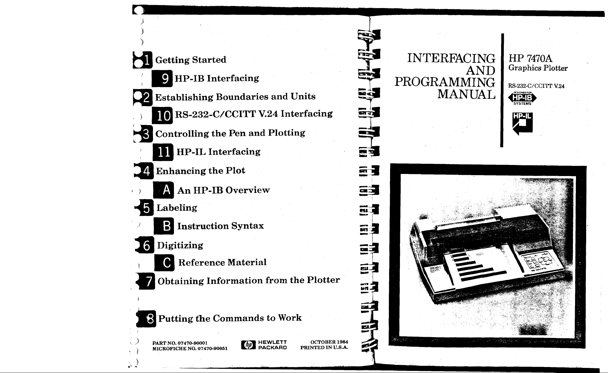
INTERFACING
AND
PROGRAMMING
MANUAL
HP 7470A
Graphics Plotter
RS-232-C/CCITT V.24
..DESIGNED FOB..
'SYSTEMS'
P
Jtl Digitizing
Reference Material
Obtaining Information from the Plotter
^ Putting the Commands to Work
ID
) PART
\ MICROFICHE NO. 07470-90051 LfiM PACKARD PRINTED IN U.S.A.
NO.
07470-90001 WAo% HEWLETT OCTOBER 1984
Page 2
)
)
)
)
)
)
J
"\
)
)
3
3
1
/
)
tbutiitmt.
)
J
')
)
')
)
Page 3
•"
')
■)
-s
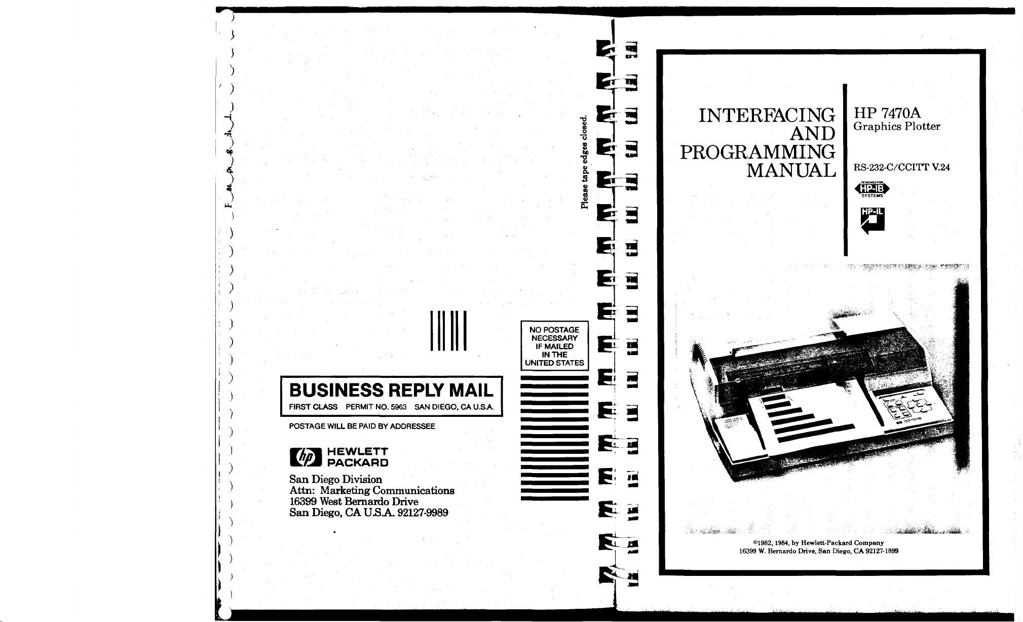
INTERFACING
AND
HP 7470A
Graphics Plotter
PROGRAMMING
MANUAL
s
^
RS-232-C/CCITT V.24
p
S
NO POSTAGE
NECESSARY
IF MAILED
IN
THE
UNITED STATES
BUSINESS REPLY MAIL
FIRST CLASS PERMIT
NO.
5963 SAN DIEGO. CA
U.S.A.
POSTAGE WILL BE PAID BY ADDRESSEE
HEWLETT
E£l
San Diego Division
Attn: Marketing Communications
16399 West Bernardo Drive
San Diego, CA U.S
PACKARD
A.
92127-9989
©1982,
16399 W. Bernardo Drive. San Diego, CA 921271899
1984, by Hewlett-Packard Company
-rti^sto*
''-Seim— . *- '***!&
Page 4
&
■.
Sd
,1
»j
i
Vfl
'>*S.
Page 5
)
Manual Summary
Chapter 1: Getting Started
Contains information concerning manual usage, a description of the
plotter, its interfaces, the HP-GL language, and three instructions.
Chapter 2: Establishing Boundaries and Units
Explains the concept of plotting area, plotter and user units, scaling,
and the instructions used to set and output the scaling points and
window, and to scale the plotting area.
Chapter 3: Controlling the Pen and Plotting
Describes the instructions for pen control and vector plotting.
Chapter 4: Enhancing the Plot
Describes instructions for drawing tick marks and differentiating traces.
Chapter 5: Labeling
Describes the instructions used in labeling to set direction, size, and
slant of characters, as well as instructions for character set and label
terminator selection and for designing your own characters.
Chapter 6: Digitizing
Describes the instructions used to digitize with the plotter and demonstrates how to check for the presence of a digitized point.
Chapter 7: Obtaining Information from the Plotter
Describes the instructions used to obtain information about pen position, errors, and capabilities of the plotter.
Chapter 8: Putting the Commands to Work
A step-by-step example illustrating the procedures to be followed to
draw labels and plot data using HP-GL instructions.
Chapter 9: HP-IB Interfacing
Summarizes operation of the plotter with the Hewlett-Packard Interface
Bus (HP-IB) and explains the methods for addressing and sending and
receiving data over the interface bus.
Manual Summary (Continued)
Appendix B: Instruction Syntax
Provides a summary of both HP-GL and device control instructions.
Appendix C: Reference Material
Includes a summary of default conditions, error messages, scaling
equations, NOP instructions, ASCII codes, and character sets.
Chapter 10: RS-232-C/CCITT V.24 Interfacing
Describes how to connect the plotter with a terminal and/or computer,
summarizes the methods for establishing a handshake protocol be-
tween the plotter and computer, and explains the device control instruc-
tions that are used to set up and control the handshake protocol.
Chapter 11: HP-IL Interfacing
Describes the Hewlett-Packard Interface Loop (HP-IL) and explains the
methods for sending and receiving data over the interface loop.
Appendix A: An HP-IB Overview
Provides an overview of the Hewlett-Packard Interface Bus (HP-IB).
ii MANUAL SUMMARY
MANUAL SUMMARY iii
Page 6
)
)
)
)
)
)
)
)
)
)
)
)
3
)
)
mm
)
)
)
)
)
)
)
)
)
)
)
)
)
)
)
Page 7
Table of Contents
Chapter 1: Getting Started
What You'll Learn in This Chapter
HP-GL Instructions Covered
Terms You Should Understand
How to Use HP 7470 Documentation
For First Encounters with the 7470
For First Encounters with HP-GL
For Experienced HP-GL Programmers
Understanding Manual Conventions and Syntax
A Brief Look at the 7470 Plotter
The 7470 Plotter's Instruction Set
HP-GL Syntax
How to Use the Examples in This Manual 1
The Default Instruction, DF 1
The Initialize Instruction, IN 1
The Input Mask Instruction, IM 1
Looking Ahead 1
Chapter 2: Establishing Boundaries and Units 2-1
What You'll Learn in This Chapter 2-1
HP-GL Instructions Covered 2-1
Terms You Should Understand 2-1
The Plotting Area 2-2
Unit Systems 2-3
The Plotter Unit 2-3
User Units 2-3
Setting the Scaling Points 2-3
Setting PI and P2 Manually 2-4
The Input PI and P2 Instruction, IP 2-4
The Output PI and P2 Instruction, OP 2-5
The Scale Instruction, SC 2-6
The Input Window Instruction, IW 2-9
The Output Window Instruction, OW 2-10
Advanced Programming Tips 2-11
Chapter 3: Controlling the Pen and Plotting 3-1
What You'll Learn in This Chapter 3-1
HP-GL Instructions Covered 3-1
Terms You Should Understand 3-1
; iv TABLE OF CONTENTS
P ::"! Table of Contents (Continued)
Chapter 3: Controlling the Pen and Plotting (Continued)
rrm
fgr 3^
C 3
iR.
^0~ MM Plotting with Variables 3-11
The Pen
The Select Pen Instruction, SP 3-2
The Velocity Select
-™ The Plot Absolute Instruction, PA 3-4
The Plot Relative Instruction, PR 3-8
~~ The Circle Instruction, CI 3-12
am The Arc Absolute Instruction, AA 3-17
Instructions, PU and PD 3-2
Instruction, VS 3-3
5
~U3 The Arc Relative Instruction, AR 3-19
^T 3 Chapter 4: Enhancing the Plot 4-1
" What You'll Learn in This Chapter 4-1
_ n HP-GL Instructions Covered 4-1
!■'
IB The Tick Instructions, XT and YT 4-2
The Tick Length Instruction, TL 4-2
P: 3 The Symbol Mode Instruction, SM 4-4
~ - J The Line Type Instruction, LT 4-6
jm:
:a^ Chapter 5: Labeling 5-1
What You'll Learn in This Chapter 5-1
; "J HP-GL Instructions Covered 5-1
E
:
™ Terms You Should Understand 5-1
Plotter Character Sets 5-2
E; ill The Designate Standard Character Set Instruction, CS 5-3
The Designate Alternate Character Set Instruction, CA 5-4
f *m The Select Standard Set Instruction, SS 5-4
C': ifl The Select Alternate Set Instruction, SA 5-5
i The Define Terminator Instruction, DT 5-6
C i ^3 The Label Instruction, LB 5-7
Labeling with Variables 5-9
,. The Absolute Direction Instruction, DI 5-10
E
1
i3 The Relative Direction Instruction, DR 5-11
Spacing Between Characters 5-12
C; fj The Character Plot Instruction, CP 5-13
' The Absolute Character Size Instruction, SI 5-15
_j^
The Relative Character Size Instruction, SR 5-16
Rll3 The Character Slant Instruction, SL 5-18
x
»fc^
--"3 TABLE OF CONTENTS V
Page 8
)
)
)
)
)
)
)
)
)
3
)
3
)
)
3
3
3
'iff-iftti!iiTiffiriiiiiii»iiiiiiMiii
3
)
)
)
)
)
3
)
)
)
3
)
)
3
3
m
Page 9
>
Table of Contents (Continued)
) Chapter 5: Labeling (Continued)
)
) Advanced Programming Tips 5-27
) What You'll Learn in This Chapter 6-1
\ HP-GL Instructions Covered 6-1
) The Digitize Point Instruction, DP 6-2
)
) Digitizing with the 7470 6-4
) Manual Method 6-4
) HP-GL Instructions Covered 7-1
x Terms You Should Understand 7-1
) Notes for an HP-IB User 7-2
) The Output Status Instruction, OS 7-8
\ Summary of Output Response Types 7-9
( )
The User Defined Character Instruction, UC 5-19
Parameter Interaction in Labeling Commands 5-21
Chapter 6: Digitizing 6-1
Terms You Should Understand 6-1
Preparing Your Plotter for Use as a Digitizer 6-2
The Digitize Clear Instruction, DC 6-3
The Output Digitized Point and Pen Status Instruction, OD 6-3
Monitoring the Status Byte 6-5
HP-IB Interrupts and Polling 6-7
Chapter
7:
Obtaining Information From the Plotter 7-1
What You'll Learn in This Chapter 7-1
A Brief Word about Plotter Output 7-2
Notes for an RS-232-C User 7-2
Notes for an HP-IL User 7-2
The Output Actual Position and Pen Status
Instruction, OA 7-3
The Output Commanded Position and Pen Status
Instruction, OC 7-4
The Output Error Instruction, OE 7-5
The Output Factors Instruction, OF 7-6
The Output Identification Instruction, 01 7-7
The Output Options Instruction, 00 7-7
Table of Contents (Continued)
Chapter 8: Putting the Commands to Work 8-1
What You'll Learn in This Chapter 8-1
Problem 8-2
Solution 8-2
Setup and Scaling 8-2
The Axes and Their Labels 8-3
Adding Color and Emphasis 8-5
Plotting Your Data 8-6
Listing 8-9
Advanced Programming Tips 8-10
Filling and Hatching 8-10
Filling a Bar 8-10
Hatching a Bar 8-12
Filling Segments of Pie Charts 8-13
Chapter 9: HP-IB Interfacing 9-1
What You'll Learn in This Chapter 9-1
HP-IB Implementation on the 7470 9-2
Interface Switches and Controls 9-2
Addressing the Plotter 9-2
Bus Commands ■ 9-4
Reaction to Bus Commands DCL, SDC, and IFC 9-4
Serial and Parallel Polling 9-4
Addressing the 7470 as a Talker or Listener 9-6
Computers with No High Level I/O Statements 9-6
Computer with High Level I/O Statements 9-6
Sending and Receiving Data 9-7
Computer-to-Plotter 9-7
Plotter-to-Computer 910
Chapter 10: RS-232-C/CCITT V.24 Interfacing 10-1
What You'll Learn in This Chapter 10-1
Setting Up Your RS-232-C Plotter: a Checklist 10-2
Plotter Environments 10-2
Using a Plotter Directly Connected to a
Computer Mainframe or Personal Computer 10-2
Using a Plotter in an Environment with a Terminal 10-4
Using the Plotter in a Terminal-only Environment 10-9
Connecting the RS-232-C Interface 10-10
VI TABLE OF CONTENTS
J
TABLE OF CONTENTS Vll
Page 10
)
)
)
)
)
)
3
3
)
3
3
)
)
)
)
3
3
MiiiniUiwWiiiiiiii iiiiniiir'fii -iniraBiTu utiiirwi-Tn--i-nr r r .r-.inrn iMfin.1 - .ir-.ii^.,.■ i«->i ^-n-mi.,.,!,,.
^,
MiM^m^m^MmMmWaKK^^a--^-.
3
3
)
3
)
)
)
3
)
)
)
)
)
)
3
)
ammiMmimmmm
Page 11

Table of Contents (Continued)
) Chapter 10: RS-232-C/CCITT V.24 Interfacing (Continued)
\ Output Baud Rate 10-12
Stop Bits 10-13
-' Transmission Errors 10-13
) Handshaking 10-14
N
Software Checking
Page 12
)
)
)
)
)
)
)
3
')
)
)
)
)
)
)
)
)
mm
)
)
)
:>
)
)
)
)
)
)
)
)
)
)
)
Page 13
HP-IL — Hewlett-Packard Interface Loop — an interface used on some
Hewlett-Packard personal computing products to communicate with
peripheral devices such as the 7470 plotter. The HP-IL interface is
standard on the Option 003 plotter.
)
B
)
How to Use HP 7470 Documentation
) This manual contains interfacing and programming information for
the HP 7470 Plotter and all its interfacing options. The Option 001
plotter is equipped with the RS-232-C/CCITT V.24 Interface. The Option
002 plotter is interfaced through the Hewlett-Packard Interface Bus
(HP-IB) which conforms to ANSI/IEEE 488-1978 specifications. The
Option 003 plotter is equipped with the Hewlett-Packard Interface Loop
for personal computing devices. All interfaces use the Hewlett-Packard
Graphics Language (HP-GL) for control of plotter graphics capabilities.
Unless specifically noted, all information in this manual pertains to all
configurations.
NOTE: All information in this manual for Option 001 plotters applies
equally to RS-232-C and CCITT V.24 interfaces. For purposes of simplicity, both are referred to as RS-232-C. ■
Documentation for this plotter is designed to enable you to use the
plotter easily without reading unnecessary manuals. All plotters are
shipped with this manual, an Operator's Manual (Part No. 07470-
90002), an Interconnection Guide (07470-90003), and a Reference Card
(07470-90004). The Operator's Manual contains all information you will
need to operate, but not program, the plotter. The Interconnect Guide
explains how to physically connect your plotter to certain computers or
calculators, and contains instructions for verifying that the connection
has been made. The Reference Card contains a list of the plotter's HP-
GL instructions with their parameters, its device control instructions
for the RS-232-C version, and a list of error numbers and their meanings.
For First Encounters with the 7470
If you have just received your HP 7470, read the Operator's Manual
and the Interconnection Guide before attempting to operate the plotter.
After inspecting your plotter, its power cord, and accessories as
described in the Operator's Manual, refer to the appropriate chapter of
this manual for initial setup and addressing or handshaking protocol
for your configuration. RS-232-C users should read Chapter 10, HP-IB
users should read Chapter 9, and HP-IL users should read Chapter 11.
For First Encounters with HP-GL
If you have never programmed in HP-GL, after reading the interfacing
chapter, read Chapters 1 through 5 in order. These chapters describe
the instructions you will use in almost every application. Running the
examples given with the instructions will help you learn. Next, read
Chapter 8 to see how all the instructions work together in a program.
When you have an application requiring digitizing or plotter output,
read Chapters 6 and 7.
For Experienced HP-GL Programmers
If you are an experienced HP-GL programmer, you may find Appendix
B of this manual or the Reference Card most helpful. Since there are
differences in syntax between this and other plotters, you should read
Chapter 1 of this manual before programming. The 7470 has added
capabilities not found in earlier plotters. Among these are the ability to
plot to non-integer user-unit values, to mirror labels using negative size
and direction parameters, and to output the current window values. To
understand these differences, you need to read the sections on scaling
(SC,
Chapter
and direction in Chapter 5. In the instruction set summary in Appendix
B,
page numbers for the complete description are listed with each
instruction.
2),-
plotting (PA and PR, Chapter 3), and setting label size
Understanding Manual Conventions and Syntax
Before reading any part of this manual, you should understand the
meaning of type styles, symbols, and number representation used in
text. A detailed explanation of syntax symbols is given in the section
entitled HP-GL Syntax in this chapter and Command Syntax for
Device Control Instructions in Chapter 10. The following conventions
also apply. Words typed in small boldface type are either buttons,
switches, or words actually found on the plotter or computer. Headings
in liWHiMJI type are used to help locate specific parts of the writeup of
an instruction. i:i*'ia:M^ type in a smaller size is used to denote a single
ASCII character which should be sent to the plotter. Numbers are
typed using SI (International System of Units) standards; numbers
with more than four digits are placed in groups of three, separated by a
1-2 GETTING STARTED
GETTING STARTED 1-3
Page 14
)
)
.)
)
)
)
)
)
)
)
)
)
)
)
)
)
)
MMMU
)
)
)
;
)
)
)
)
)
)
)
)
;
)
)
J
Page 15
tf
)
'
)
V
)
)
)
■■
.)
)
<:
)
;
)
'
)
<■
)
(
)
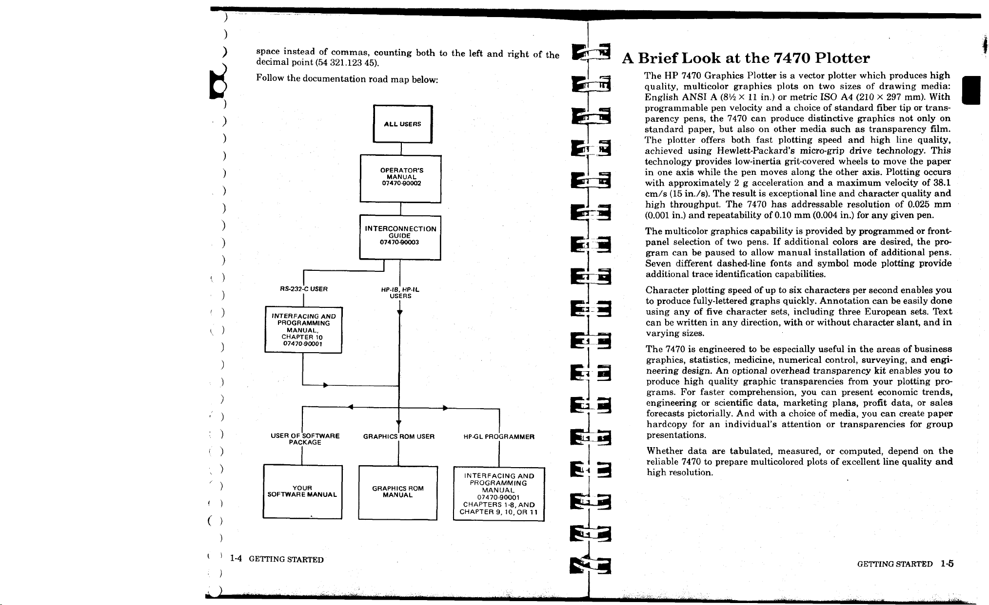
space instead of commas, counting both to the left and right of the
decimal point (54 321.123 45).
Follow the documentation road map below:
ALL USERS
OPERATOR'S
MANUAL
07470-90002
INTERCONNECTION
GUIDE
07470-90003
RS-232-C USER
INTERFACING AND
PROGRAMMING
MANUAL,
CHAPTER 10
07470-90001
HP-IB,
USERS
HP-IL
^
t
»
—4
►
•
USER OF SOFTWARE
PACKAGE
YOUR
SOFTWARE MANUAL
GRAPHICS ROM USER
GRAPHICS ROM
MANUAL
HP-GL PROGRAMMER
INTERFACING AND
PROGRAMMING
MANUAL
07470-90001
CHAPTERS 1-8, AND
CHAPTER 9, 10, OR 11
A Brief Look at the 7470 Plotter
The HP 7470 Graphics Plotter is a vector plotter which produces high
quality, multicolor graphics plots on two sizes of drawing media:
English ANSI A
programmable pen velocity and a choice of standard fiber tip or transparency pens, the 7470 can produce distinctive graphics not only on
standard paper, but also on other media such as transparency film.
The plotter offers both fast plotting speed and high line quality,
achieved using Hewlett-Packard's micro-grip drive technology. This
technology provides low-inertia grit-covered wheels to move the paper
in one axis while the pen moves along the other axis. Plotting occurs
with approximately 2 g acceleration and a maximum velocity of 38.1
cm/s (15 in./s). The result is exceptional line and character quality and
high throughput. The 7470 has addressable resolution of 0.025 mm
(0.001 in.) and repeatability of 0.10 mm (0.004 in.) for any given pen.
The multicolor graphics capability is provided by programmed or frontpanel selection of two pens. If additional colors are desired, the program can be paused to allow manual installation of additional pens.
Seven different dashed-line fonts and symbol mode plotting provide
additional trace identification capabilities.
Character plotting speed of up to six characters per second enables you
to produce fully-lettered graphs quickly. Annotation can be easily done
using any of five character sets, including three European sets. Text
can be written in any direction, with or without character slant, and in
varying sizes.
The 7470 is engineered to be especially useful in the areas of business
graphics, statistics, medicine, numerical control, surveying, and engineering design. An optional overhead transparency kit enables you to
produce high quality graphic transparencies from your plotting pro-
grams. For faster comprehension, you can present economic trends,
engineering or scientific data, marketing plans, profit data, or sales
forecasts pictorially. And with a choice of media, you can create paper
hardcopy for an individual's attention or transparencies for group
presentations.
Whether data are tabulated, measured, or computed, depend on the
reliable 7470 to prepare multicolored plots of excellent line quality and
high resolution.
(8V2 X
11 in.) or metric ISO A4 (210 X 297 mm). With
{
)
1-4 GETTING STARTED
MIMH
tJUmitmi/aH
■^^^^—
■J-^**—^-**;*
GETTING STARTED
-^.--
1-5
•,Q...i^^.
Page 16
■■•
)
)
)
0
)
)
)
)
)
)
)
)
)
)
)
)
)
m*
MMMMH
)
i
)
)
;
)
)
■'
-
)
)
;■ )
' )
\ )
)
)
.
)
)
«*_J
Page 17
)
The 7470 Plotter's Instruction Set
All three interface configurations for the HP 7470 Plotter use the same
Hewlett-Packard Graphics Language (HP-GL) instruction set, with
i
minor exceptions.* HP-GL consists of two-letter mnemonic instructions
which activate the plotter. A table listing the instructions alphabetically
is located at the end of the next section. Syntax descriptions and
explanations of these instructions are contained in Chapters 1 through
8. Six additional HP-GL instructions cause no operation but are included for compatibility with other HP plotters. These instructions are
listed in Appendix C.
Fourteen additional instructions, called device control instructions, are
required by the RS-232-C configuration. These instructions are used to
establish plotter output and handshake protocol, and to control conditions which are pertinent only to the RS-232-C environment. In an
RS-232-C plotter, all HP-GL instructions enter the plotter's internal
buffer and are executed in a first-in, first-out sequence. Device control
instructions do not enter the buffer, but instead are executed immediately upon receipt. Refer to Chapter 10 for the syntax description and
an explanation of the device control instructions.
HP-GL Syntax
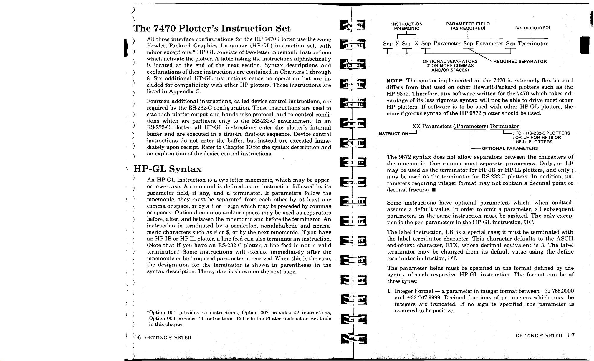
An HP-GL instruction is a two-letter mnemonic, which may be upperor lowercase. A command is defined as an instruction followed by its
parameter field, if any, and a terminator. If parameters follow the
mnemonic, they must be separated from each other by at least one
comma or space, or by a + or — sign which may be preceded by commas
or spaces. Optional commas and/or spaces may be used as separators
before, after, and between the mnemonic and before the terminator. An
instruction is terminated by a semicolon, nonalphabetic and nonnumeric characters such as # or $, or by the next mnemonic. If you have
an HP-IB or HP-IL plotter, a line feed can also terminate an instruction.
(Note that if you have an RS-232-C plotter, a line feed is not a valid
terminator.) Some instructions will execute immediately after the
mnemonic or last required parameter is received. When this is the case,
the designation for the terminator is shown in parentheses in the
syntax description. The syntax is shown on the next page.
*Option 001 provides 45 instructions; Option 002 provides 42 instructions;
Option 003 provides 41 instructions. Refer to the Plotter Instruction Set table
in this chapter.
INSTRUCTION PARAMETER FIELD
MNEMONIC (AS REQUIRED) (AS REQUIRED)
J-^L I _J
Sep X Sep X Sep Parameter Sep Parameter Sep Terminator
OPTIONAL SEPARATORS ^^ REQUIRED SEPARATOR
(0OR MORE COMMAS
AND/OR SPACES)
NOTE: The syntax implemented on the 7470 is extremely flexible and
differs from that used on other Hewlett-Packard plotters such as the
HP 9872. Therefore, any software written for the 7470 which takes ad-
vantage of its less rigorous syntax will not be able to drive most other
HP plotters. If software is to be used with other HP-GL plotters, the
more rigorous syntax of the HP 9872 plotter should be used.
XX Parameters (.Parameters) Terminator
INSTRUCTION '
OPTIONAL PARAMETERS
The 9872 syntax does not allow separators between the characters of
the mnemonic. One comma must separate parameters. Only; or LF
may be used as the terminator for HP-IB or HP-IL plotters, and only ;
may be used as the terminator for RS-232-C plotters. In addition, parameters requiring integer format may not contain a decimal point or
decimal fraction. ■
Some instructions have optional parameters which, when omitted,
assume a default value. In order to omit a parameter, all subsequent
parameters in the same instruction must be omitted. The only exception is the pen parameters in the HP-GL instruction, UC.
The label instruction, LB, is a special case; it must be terminated with
the label terminator character. This character defaults to the ASCII
end-of-text character, ETX, whose decimal equivalent is 3. The label
terminator may be changed from its default value using the define
terminator instruction, DT.
The parameter fields must be specified in the format defined by the
syntax of each respective HP-GL instruction. The format can be of
three types:
1.
Integer Format — a parameter in integer format between —32 768.0000
and +32 767.9999. Decimal fractions of parameters which must be
integers are truncated. If no sign is specified, the parameter is
assumed to be positive.
FOR RS-232-C PLOTTERS
;OR LF FOR HP-IB OR
HP-IL PLOTTERS
1-6 GETTING STARTED
Mann
«itei
GETTING STARTED 1-7
^^tmm^timtmit^tmimi^iiiitmm
Page 18
;
)
)
)
)
)
)
)
)
)
)
)
)
)
)
)
)
MlHiiiliHtfiilMiHiialli
MHWiE&i:^
mm
;
)
)
)
)
)
)
)
)
)
;
)
)
J
Page 19
)
;
)
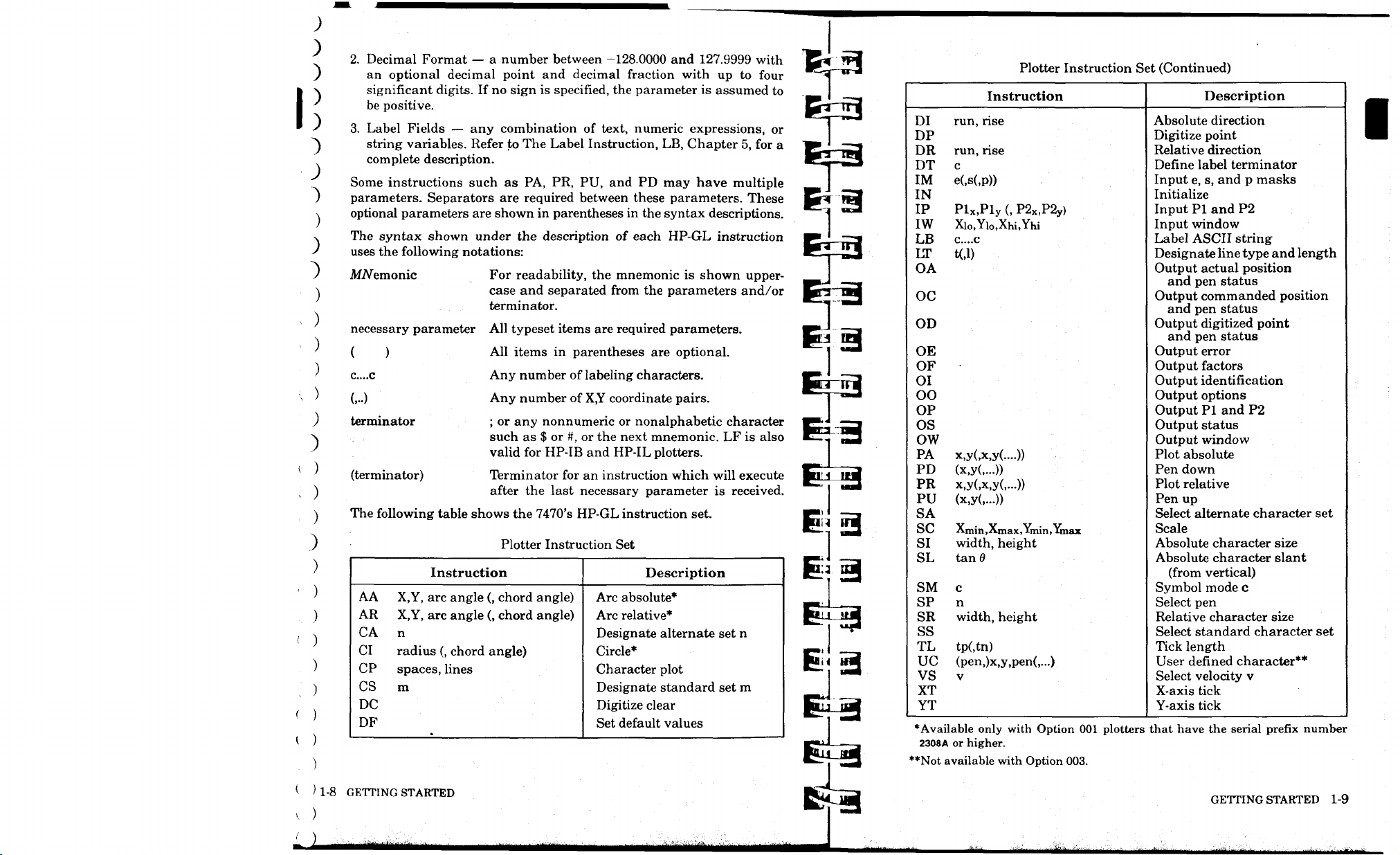
2.
Decimal Format — a number between -128.0000 and 127.9999 with
)
)
)
:>
)
)
)
)
an optional decimal point and decimal fraction with up to four
significant digits. If no sign is specified, the parameter is assumed to
be positive.
3.
Label Fields — any combination of text, numeric expressions, or
string variables. Refer to The Label Instruction, LB, Chapter 5, for a
complete description.
Some instructions such as PA, PR, PU, and PD may have multiple
parameters. Separators are required between these parameters. These
optional parameters are shown in parentheses in the syntax descriptions.
The syntax shown under the description of each HP-GL instruction
uses the following notations:
AfA/emonic
necessary parameter
( )
C....C
(...)
terminator
(terminator)
The following table shows the 7470's HP-GL instruction set.
Instruction
AA
X,Y, arc angle (, chord angle)
AR
X,Y, arc angle (, chord angle)
n
CA
CI
radius (, chord angle)
CP
spaces, lines
CS
m
DC
DF
For readability, the mnemonic is shown uppercase and separated from the parameters and/or
terminator.
All typeset items are required parameters.
All items in parentheses are optional.
Any number of labeling characters.
Any number of X,Y coordinate pairs.
; or any nonnumeric or nonalphabetic character
such as $ or #, or the next mnemonic. LF is also
valid for HP-IB and HP-IL plotters.
Terminator for an instruction which will execute
after the last necessary parameter is received.
Plotter Instruction Set
Description
Arc absolute*
Arc relative*
Designate alternate set n
Circle*
Character plot
Designate standard set m
Digitize clear
Set default values
Plotter Instruction Set (Continued)
Description
run, rise
DI
DP
DR
run, rise
c
DT
IM
e(,s(,p))
IN
IP
Plx.Ply (, P2x,P2y)
IW
Xio,Yi0,Xhi,Yhi
C....C
LB
LT
t(,l)
OA
Instruction
Absolute direction
Digitize point
Relative direction
Define label terminator
Input e, s, and p masks
Initialize
Input PI and P2
Input window
Label ASCII string
Designate line type and length
Output actual position
and pen status
OC
Output commanded position
and pen status
OD
Output digitized point
and pen status
OE
OF
OI
OO
OP
OS
OW
PA
x,y(,x,y(....))
PD
(x,y(,...))
PR
x,y(,x,y(,...))
PU
(x,y(,...))
SA
SC
Xmin,Xmax,Ymin,Ymax
SI
width, height
SL
tan 0
Output error
Output factors
Output identification
Output options
Output PI and P2
Output status
Output window
Plot absolute
Pen down
Plot relative
Pen up
Select alternate character set
Scale
Absolute character size
Absolute character slant
(from vertical)
SM
c
SP
n
SR
width, height
ss
TL
tp(,tn)
UC
(pen,)x,y,pen(,...)
V
VS
XT
YT
*Available only with Option 001 plotters that have the serial prefix number
2308A or higher.
'*Not available with Option 003.
Symbol mode c
Select pen
Relative character size
Select standard character set
Tick length
User denned character**
Select velocity v
X-axis tick
Y-axis tick
1-8 GETTING STARTED
MMiiiHiiiitaMii
GETTING STARTED 1-9
warn
Page 20
)
)
)
)
)
)
)
)
)
)
)
)
)
)
)
)
)
)
)
)
)
)
)
)
)
)
;
>
>
)
Page 21
£low to Use the Examples in This Manual
The examples in this manual are designed primarily to show the use of
) the instruction with which they appear. New programmers are strongly
A encouraged to enter and run all examples. When the example consists
of only a few HP-GL commands, these commands are listed in quotes.
) No line numbers or BASIC statements are included. The literal string
A
listed should be sent to the plotter; the quotation marks only serve to
J delimit the string and are included because many computer languages
~) define literal strings by placing them inside quotation marks. Do not
send the quotation marks to the plotter.
Longer examples are given as programs or program segments in
) BASIC. The programs will run only if the plotter has been defined as
A
the system printer. Since the statement to do this is highly system-
dependent, it is not included (except in Chapter 8). Unless specific
) mention is made in the text, the BASIC used is that of the HP-83/85.
You may need to make slight changes in the BASIC statements for
)
them to run on your computer. You may also need an I/O ROM to
) obtain output from the plotter. Check with the nearest HP dealer or HP
Sales and Support Office. If you are operating in an RS-232-C environ-
) ment, you will need to establish handshaking protocol and include the
\ necessary device control statements in your program.
If you are programming in another language, substitute the output or
)
input commands of your language for the BASIC statements PRINT
) and ENTER. Change FOR...NEXT loops and replacement statements
(X = 3.14) to whatever statements are comparable in your language. All
) characters enclosed in quotes in the program listing must be sent to the
^ computer using output statements; in addition, some variables, which
are not included in quotes, may need to be sent.
Refer to Chapter 9 for some examples of complete simple programs to
) send and receive information between the plotter and specific com-
puters in an HP-IB environment. The Interconnection Guide (07470-
90003) has some examples of sending HP-GL commands from specific
) computers; there are examples using RS-232-C, HP-IB, and HP-IL
interfaces in that document.
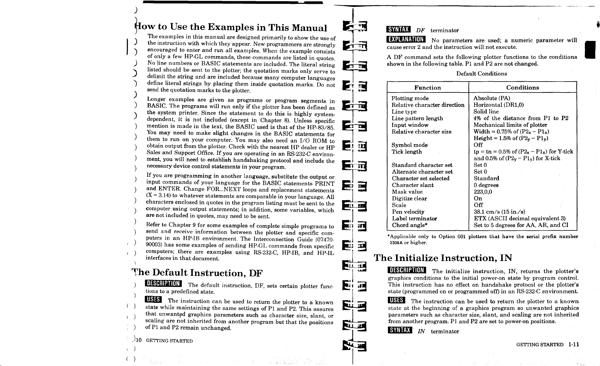
KMiUlEl DF terminator
No parameters are used; a numeric parameter will
cause error 2 and the instruction will not execute.
A DF command sets the following plotter functions to the conditions
shown in the following table. PI and P2 are not changed.
Default Conditions
Function
Plotting mode
Relative character direction
Line type
Line pattern length
Input window
Relative character size
Symbol mode
Tick length
Standard character set
Alternate character set
Character set selected
Character slant
Mask value
Digitize clear
Scale
Pen velocity
Label terminator
Chord angle*
*Applicable only to Option 001 plotters that have the serial prefix number
2308A or higher.
Absolute (PA)
Horizontal (DR1.0)
Solid line
4%
of the distance from PI to P2
Mechanical limits of plotter
Width = 0.75% of (P2X - Plx)
Height = 1.5% of (P2y - Ply)
Off
tp = tn = 0.5% of (P2X - Plx) for Y-tick
and 0.5% of (P2y - Ply) for X-tick
SetO
SetO
Standard
0 degrees
223,0,0
On
Off
38.1 cm/s (15 in./s)
ETX (ASCII decimal equivalent 3)
Set to 5 degrees for AA, AR, and CI
Conditions
The Initialize Instruction, IN
The Default Instruction, DF
tions to a predefined state.
)
f
<
lUaxl The instruction can be used to return the plotter to a known
)
state while maintaining the same settings of PI and P2. This assures
j that unwanted graphics parameters such as character size, slant, or
scaling are not inherited from another program but that the positions
) of Pi and P2 remain unchanged.
JlO GETTING STARTED
)
)
The default instruction, DF, sets certain plotter func-
The initialize instruction, IN, returns the plotter's
graphics conditions to the initial power-on state by program control.
This instruction has no effect on handshake protocol or the plotter's
state (programmed on or programmed off) in an RS-232-C environment.
The instruction can be used to return the plotter to a known
state at the beginning of a graphics program so unwanted graphics
parameters such as character size, slant, and scaling are not inherited
from another program. PI and P2 are set to power-on positions.
■tWlftyi IN terminator
GETTING STARTED 1-11
Page 22

)
)
)
)
)
)
)
)
)
)
)
)
)
)
)
)
)
)
)
)
)
)
)
)
)
)
;
)
)
)
)
)
)
Page 23
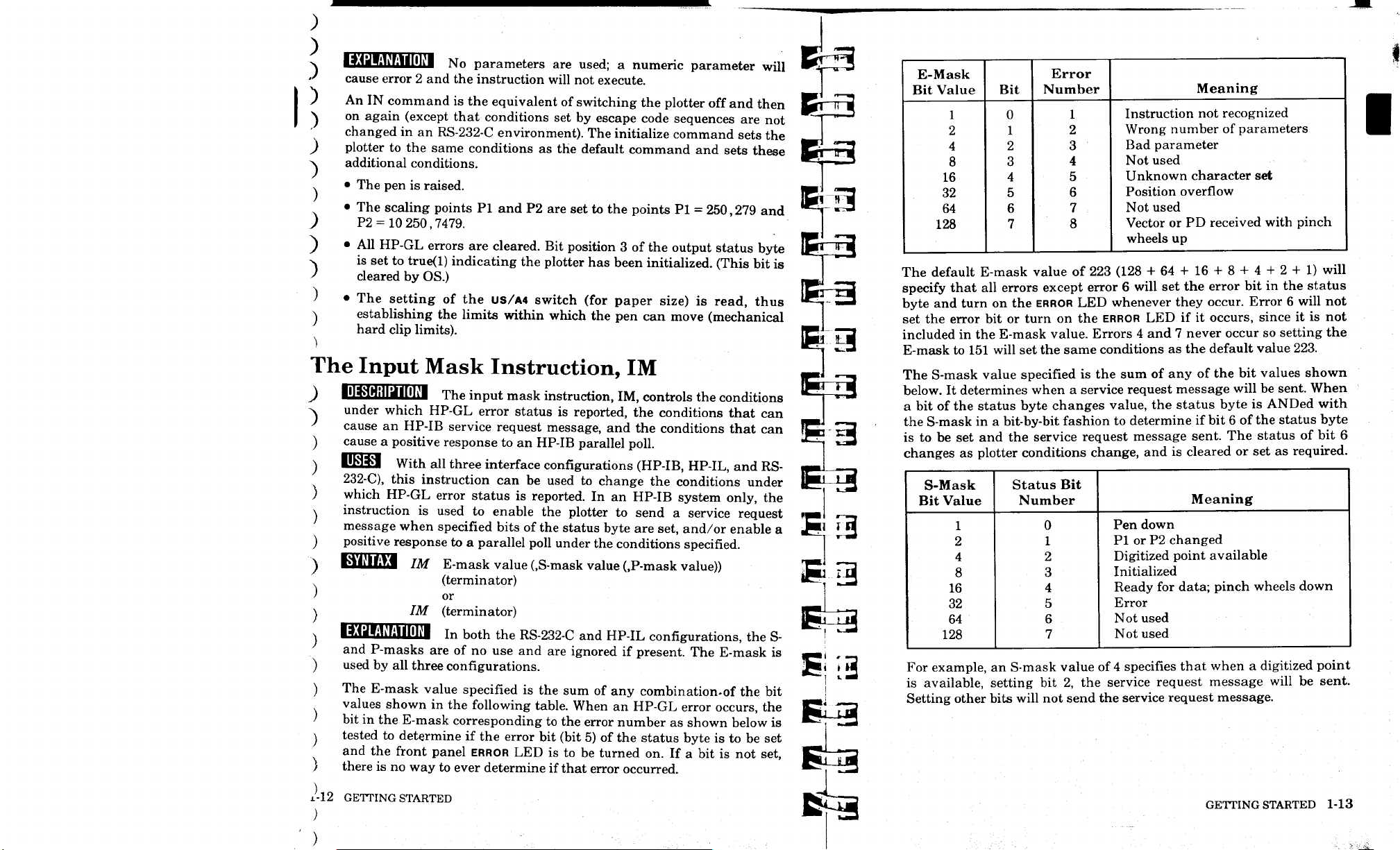
>. I^HUMi'MIHli'l NO parameters are used; a numeric parameter will K.-—«-3
J cause error 2 and the instruction will not execute. I
) An IN command is the equivalent of switching the plotter off and then
"\ on again (except that conditions set by escape code sequences are not
changed in an RS-232-C environment). The initialize command sets the
) plotter to the same conditions as the default command and sets these
additional conditions.
)
v • The pen is raised. 1ft! ™^3
• The scaling points Pi and P2 are set to the points PI = 250,279 and ^~ "^
) P2 = 10 250,7479.
) • All HP-GL errors are cleared. Bit position 3 of the output status byte ifW' J| j
-v is set to true(l) indicating the plotter has been initialized. (This bit is 1
) cleared by OS.) '
) • The setting of the US/A4 switch (for paper size) is read, thus
\ establishing the limits within which the pen can move (mechanical
hard clip limits).
T
El SJ
The Input Mask Instruction, IM
J HlwHHIillFlltl The input mask instruction, IM, controls the conditions
~N
under which HP-GL error status is reported, the conditions that can
' cause an HP-IB service request message, and the conditions that can
cause a positive response to an HP-IB parallel poll.
UWM With all three interface configurations (HP-IB, HP-IL, and RS- —*
232-C),
this instruction can be used to change the conditions under fT^~^~3
which HP-GL error status is reported. In an HP-IB system only, the
instruction is used to enable the plotter to send a service request «! r-—.
message when specified bits of the status byte are set, and/or enable a i^' J_3
positive response to a parallel poll under the conditions specified.
--" " " " \
"\ BJiJIiftl IM E-mask value (,S-mask value (,P-mask value))
(terminator)
or
IM (terminator)
■9<JI:Ui1llllfl
and P-masks are of no use and are ignored if present. The E-mask is H J , _
used by all three configurations. J5« ^Jj
The E-mask value specified is the sum of any combination.of the bit
values shown in the following table. When an HP-GL error occurs, the
bit in the E-mask corresponding to the error number as shown below is
tested to determine if the error bit (bit 5) of the status byte is to be set
and the front panel
there is no way to ever determine if that error occurred.
In both
the RS-232-C and HP-IL configurations, the S-
ERROR
LED is to be turned on. If a bit is not set,
3
EH3
E-Mask
Bit Value
1
2
4
8
16
32
64
128
The default E-mask value of 223 (128 + 64 + 16 + 8 + 4 + 2 + 1) will
specify that all errors except error 6 will set the error bit in the status
byte and turn on the ERROR LED whenever they occur. Error 6 will not
set the error bit or turn on the ERROR LED if it occurs, since it is not
included in the E-mask value. Errors 4 and 7 never occur so setting the
E-mask to 151 will set the same conditions as the default value 223.
The S-mask value specified is the sum of any of the bit values shown
below. It determines when a service request message will be sent. When
a bit of the status byte changes value, the status byte is ANDed with
the S-mask in a bit-by-bit fashion to determine if bit 6 of the status byte
is to be set and the service request message sent. The status of bit 6
changes as plotter conditions change, and is cleared or set as required.
S-Mask
Bit Value
1
2
4
8
16
32
64
128
For example, an S-mask value of 4 specifies that when a digitized point
is available, setting bit 2, the service request message will be sent.
Setting other bits will not send the service request message.
Bit
0
1
2
3
4
5
6
7
Error
Number
1
2
3
4
5
6
7
8
Status Bit
Number
0
1
2
3
4
5
6
7
Instruction not recognized
Wrong number of parameters
Bad parameter
Not used
Unknown character set
Position overflow
Not used
Vector or PD received with pinch
wheels up
Pen down
PI or P2 changed
Digitized point available
Initialized
Ready for data; pinch wheels down
Error
Not used
Not used
Meaning
Meaning
12 GETTING STARTED
GETTING STARTED 1-13
Page 24
)
)
)
)
)
)
)
)
)
)
)
)
)
)
)
)
)
)
)
)
)
)
)
)
)
)
)
)
)
)
)
)
)
Page 25
)
)
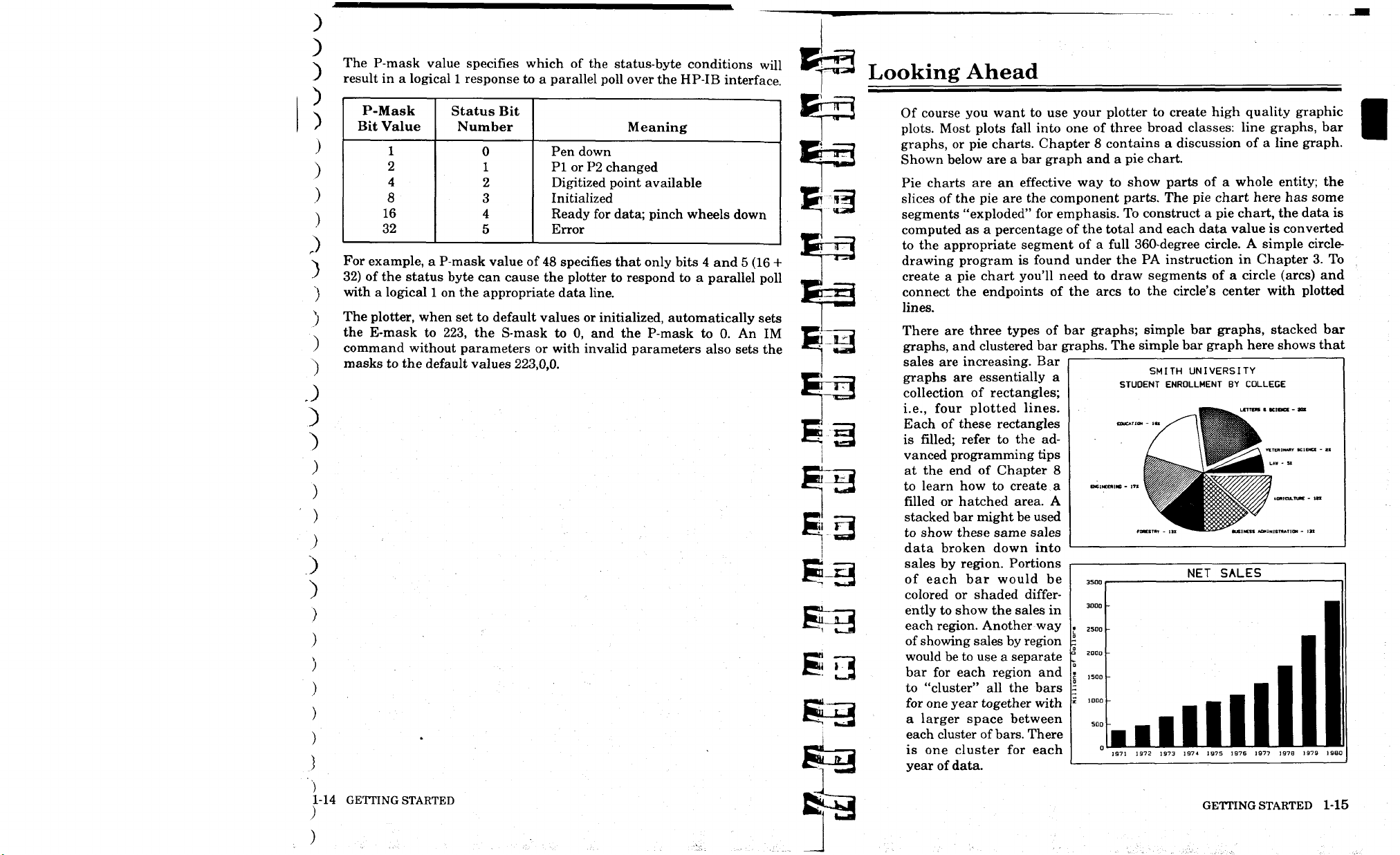
The P-mask value specifies which of the status-byte conditions will
)
result in a logical 1 response to a parallel poll over the HP-IB interface.
)
)
)
)
)
)
.)
)
)
)
)
)
P-Mask
Bit Value
1
2
4
8
16
32
For example, a P-mask value of 48 specifies that only bits 4 and 5 (16 +
32) of the status byte can cause the plotter to respond to a parallel poll
with a logical 1 on the appropriate data line.
The plotter, when set to default values or initialized, automatically sets
the E-mask to 223, the S-mask to 0, and the P-mask to 0. An IM
command without parameters or with invalid parameters also sets the
masks to the default values 223,0,0.
Status Bit
Number
0
1
2
3
4
5
Meaning
Pen down
PI or P2 changed
Digitized point available
Initialized
Ready for data; pinch wheels down
Error
J
)
;
)
)
)
)
1-14 GETTING STARTED
)
^
EE3
^3
Looking Ahead
Of course you want to use your plotter to create high quality graphic
plots.
Most plots fall into one of three broad classes: line graphs, bar
graphs, or pie charts. Chapter 8 contains a discussion of a line graph.
Shown below are a bar graph and a pie chart.
Pie charts are an effective way to show parts of a whole entity; the
slices of the pie are the component parts. The pie chart here has some
segments "exploded" for emphasis. To construct a pie chart, the data is
computed as a percentage of the total and each data value is converted
to the appropriate segment of a full 360-degree circle. A simple circledrawing program is found under the PA instruction in Chapter 3. To
create a pie chart you'll need to draw segments of a circle (arcs) and
connect the endpoints of the arcs to the circle's center with plotted
lines.
There are three types of bar graphs; simple bar graphs, stacked bar
graphs, and clustered bar graphs. The simple bar graph here shows that
sales are increasing. Bar
graphs are essentially a
collection of rectangles;
i.e., four plotted lines.
Each of these rectangles
is filled; refer to the advanced programming tips
at the end of Chapter 8
to learn how to create a
filled or hatched area. A
stacked bar might be used
to show these same sales
data broken down into
sales by region. Portions
of each bar would be
colored or shaded differ-
ently to show the sales in
each region. Another way
of showing sales by region
would be to use a separate
bar for each region and
to "cluster" all the bars
for one year together with
a larger space between
each cluster of
is one cluster for each
year of data.
bars.
There
3000
2500
I
a
2000
■5
1500
|
1000
i
SQQ
0
m.
SMITH UNIVERSITY
STUDENT ENROLLMENT BY COLLEGE
fORKTRT - I!
NET SALES
■
■
ml
JLL
1972
1971
III!
1973
1974 1975 1976 1977
GETTING STARTED 1-15
VETERINARY SCIENCE - 21
LAW - S*
AGRICULTURE - IB
1
M.
■
■
1
■ ■
■ ■
1
1979
1978
Ml
19B0
Page 26
;
)
,)
)
)
)
^
)
)
)
)
)
)
)
)
)
)
)
)
')
)
)
)
)
)
)
)
>
)
)
)
)
Page 27
Chapter
Establishing Boundaries
and Units
What You'll Learn in This Chapter
In this chapter you will learn about the plotting area, how to define a
point in this area, and the two kinds of units used to describe the plotting area. After reading this chapter, you will be able to decide which
units to use for your data. In addition, you will be able to scale the
plotting area into user units appropriate for your data, and to set or
read the current scaling points. You will be able to restrict plotting to
only a portion of the plotting area, and read the current limits of the
plotting area.
HP-GL Instructions Covered
IP The Input PI and P2 Instruction
OP The Output PI and P2 Instruction
SC The Scale Instruction
IW The Input Window Instruction
OW The Output Window Instruction
Terms You Should Understand
Scaling — dividing the plotting area into units convenient for your application. Units need not be the same physical size in both axes, nor do
there need to be an equal number of units in the X- and Y-axes.
Scaling Points — the points on the plotting surface moved to when the
front panel buttons
user-unit values specified by the parameters of the scaling instruction
SC.
Window — that part of the plotting area in which plotting of points,
lines,
and labels can occur. At power on, the window is set to the
mechanical limits of the plotter. Nothing can be drawn outside the
current window.
Clipping — restricting plotting to a portion of the plotting area by
establishing a window of a certain size.
P1
and P2 are pressed. These points are assigned the
ESTABLISHING BOUNDARIES AND UNITS 2-1
Page 28
)
3
:>
)
)
)
.)
)
)
)
>
)
)
)
)
)
)
)
)
)
)
-")
)
)
)
)
)
.)
)
)
Page 29
J
)
?he Plotting Area
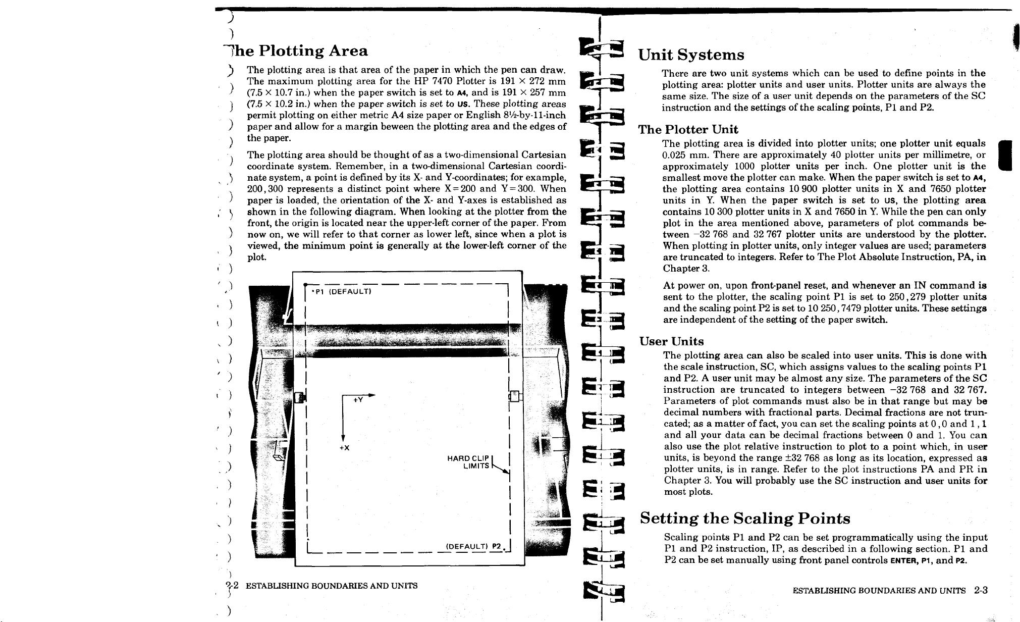
The plotting area is that area of the paper in which the pen can draw.
)
The maximum plotting area for the HP 7470 Plotter is 191 X 272 mm
)
(7.5 X 10.7 in.) when the paper switch is set to A4, and is 191 X 257 mm
(7.5 X 10.2 in.) when the paper switch is set to us. These plotting areas
)
permit plotting on either metric A4 size paper or English
paper and allow for a margin beween the plotting area and the edges of
)
the paper.
)
The plotting area should be thought of as a two-dimensional Cartesian
coordinate system. Remember, in a two-dimensional Cartesian coordinate system, a point is defined by its X- and Y-coordinates; for example,
200,300 represents a distinct point where X = 200 and Y =
paper is loaded, the orientation of the X- and Y-axes is established as
shown in the following diagram. When looking at the plotter from the
front, the origin is located near the upper-left corner of the paper. From
now on, we will refer to that corner as lower left, since when a plot is
viewed, the minimum point is generally at the lower-left corner of the
plot.
8'/2-by-l
300.
1-inch
When
Unit Systems
There are two unit systems which can be used to define points in the
plotting area: plotter units and user units. Plotter units are always the
same size. The size of a user unit depends on the parameters of the SC
instruction and the settings of the scaling points, PI and P2.
The Plotter Unit
The plotting area is divided into plotter units; one plotter unit equals
0.025 mm. There are approximately 40 plotter units per millimetre, or
approximately 1000 plotter units per inch. One plotter unit is the
smallest move the plotter can make. When the paper switch is set to A4,
the plotting area contains 10 900 plotter units in X and 7650 plotter
units in Y. When the paper switch is set to us, the plotting area
contains 10 300 plotter units in X and 7650 in Y. While the pen can only
plot in the area mentioned above, parameters of plot commands between —32 768 and 32 767 plotter units are understood by the plotter.
When plotting in plotter units, only integer values are used; parameters
are truncated to integers. Refer to The Plot Absolute Instruction, PA, in
Chapter 3.
- )
< )
, )
' )
1 (DEFAULT)
-,i
.-wmwmmwL>mmi^w,mL
+Y
+X
HARD CLIP
LIMITS
(DEFAULT) P2
Si 3
gkj
At power on, upon front-panel reset, and whenever an IN command is
sent to the plotter, the scaling point PI is set to 250,279 plotter units
and the scaling point P2 is set to 10 250,7479 plotter units. These settings
are independent of the setting of the paper switch.
User Units
The plotting area can also be scaled into user units. This is done with
the scale instruction, SC, which assigns values to the scaling points PI
and P2. A user unit may be almost any size. The parameters of the SC
instruction are truncated to integers between -32 768 and 32 767.
Parameters of plot commands must also be in that range but may be
decimal numbers with fractional parts. Decimal fractions are not truncated; as a matter of fact, you can set the scaling points at 0,0 and 1,1
and all your data can be decimal fractions between 0 and 1. You can
also use the plot relative instruction to plot to a point which, in user
units,
is beyond the range ±32 768 as long as its location, expressed as
plotter units, is in range. Refer to the plot instructions PA and PR in
Chapter 3. You will probably use the SC instruction and user units for
most plots.
Setting the Scaling Points
Scaling points PI and P2 can be set programmatically using the input
PI and P2 instruction, IP, as described in a following section. PI and
P2 can be set manually using front panel controls ENTER, PI, and
P2.
of2
ESTABLISHING BOUNDARIES AND UNITS
)
ESTABLISHING BOUNDARIES AND UNITS 2-3
Page 30
)
;
")
)
)
)
)
)
)
)
)
)
)
)
)
)
)
)
)
)
)
)
)
)
)
)
)
Page 31

)
netting PI and P2 Manually
) P2 moves when Pi is moved manually. If you want P2 to be at a
specific location, set PI first and then P2. If you want to establish an
)
area of a certain size onto which the parameters of a scale instruction
)
will be mapped, you may set P2 in the desired location relative to the
current PI, and then move Pi. P2 will move to a corresponding location
)
so that both the X- and Y-distances between PI and P2 remain con-
stant. If such a move means the new location of P2 will be beyond the
;
plotting area, either or both coordinates of P2 are set to the plotting
limits.
In this case, the size of the rectangle established by PI and P2
will, of course, not remain the same. A detailed description, including
illustrations, is contained in the HP 7470 Operator's Manual.
)
To set PI or P2 manually:
)
1.
Move the pen to the desired location using the front panel arrow
buttons.
>
2.
Press ENTER simultaneously with
the pen will merely move to PI or P2 and no change in the location
) of PI or P2 will occur.
) 3. Check the new locations of the scaling points by pressing P1; then
\ press P2.
P1
or
P2.
If ENTER is not held down,
'he Input PI and P2 Instruction, IP
DESCRIPTION
means to relocate PI and P2 through program control.
lifilxi The IP instruction is often used to ensure that a plot is always
the same size, especially when the user and programmer are not the
same person. It establishes program control of plot size and label direction. This instruction can also be used to move the scaling points PI
and P2 from their default or current locations; to give mirror images of
vectors and labels; to change the size of a user unit, thus reducing or
enlarging an image; to change the size or direction of labels when
relative character size or direction is in effect; and to set PI and P2
back to their default locations.
EEEQ //•
EXPLANATION
order shown above and must be in absolute plotter units. Parameters
should be ^ 0 and within the maximum plotting area. This means
0 < X sj 10 30Q when the paper switch is set to us; 0 s$ X < 10 900 if the
paper switch is set to
The input PI and P2 instruction, IP, provides the
Plx,Ply (, P2x,P2y) (terminator)
or
IP
(terminator)
The new coordinates of Pi and P2 are specified in the
A4;
and 0
«S
Y ^ 7650 for either setting.
3
3
-a
Negative parameters greater than or equal to -32 768 will be set to zero.
Parameters outside the maximum plotting area (determined by the setting of the paper switch) but less than 32 767 will be set to the limits of
the plotting area. Parameters less than -32 768 or greater than 32 767
will cause error 3 and the coordinates of PI and P2 will not change.
An IP command without parameters will default PI and P2 to the
values 250,279,10 250,7479 regardless of the paper switch setting.
Upon receipt of a valid IP command, bit position 1 of the output status
word is set true (1).
Upon power on, front-panel reset, or execution of an IN or DF command, the character size is set relative (SR) to the locations of PI and
P2.
Unless an SI command has been entered as part of the program,
the character size will be directly affected by the IP command.
The following HP-GL command relocates the scaling points PI and P2
to the positions shown in the figure.
"IP 3000,2000,5000,5000;"
P2
#
(50005000)
• P1
(3000,2000)
The Output PI and P2 Instruction, OP
The output PI and P2 instruction, OP, provides the
means to make the current coordinates of PI and P2 available for
output.
'A
ESTABLISHING BOUNDARIES AND UNITS
( )
BS3
ESTABLISHING BOUNDARIES AND UNITS 2-5
Page 32

)
:>
)
)
)
)
)
)
)
1
)
)
)
)
)
1
)
.)
)
:>
)
)
)
)
)
)
)
)
;
Page 33

)
The Output Win
) |»|yitJHiaHllll
s means to obtain the X
right corners of the are!
) I'Hyj The instructio)
any plotting will occur
the execution of a DF
determine under progri
or A4.
EMEU OW (termi
MJWiwaii'Hi No
After an OW commam
nates of opposite corni
integers in ASCII in thi
)
)
where [TERM] is the ol
)
Should Understand in \
)
The range of the intej
switch as shown below;
)
)
)
)
If Xlower left is greater
Yupper
)
)
)
)
)
)
)
right,
The o
1
Pai
Xlower left, Yloj
US
OsSXsSK
0«S Y«S7t
no window
{
«'
)
■ )
O)
tpii
o
J
vVr)
i d
)
£0l^
trle\
pu^
)
■ )
JlA.
1 '
ist)
■■ )
)
The instruction can be used to determine the position of Pi
and P2 in plotter units. This information can be used with the input
window command, IW, to set the window to PI and P2 under program
control, to compute the number of plotter units per user unit when
scaling is on, or to determine the numeric coordinates of Pi and P2
when they have been set manually.
EffiEE] OP (terminator)
( )
EXPLANATION
put the coordinates of PI and P2 in plotter units as four integers in
ASCII in the following form:
where [TERM] is the output terminator for your system. See Terms You
Should Understand in Chapter 7.
The range of the integers is determined by the setting of the paper
switch as shown below:
<
)
o
Upon completion of output, bit position 1 of the output status byte is
cleared.
After an OP command is received, the plotter will out-
Plx,Ply,P2x,P2y [TERM]
US
0sSXsS10 300
0<Y<7650
A4
0^X^10 900
0«S YSS7650
x'he Scale Instruction, SC
DESCRIPTION
nate system by mapping values onto the scaling points PI and P2.
This instruction is used to enable you to plot in user units convenient to your application. For instance, if your X values represent
months, then Xmin = 1 and Xmax = 12. If the values for Y-coordinates
all lay between 0 and 10, you might use 0 as Ymin and 10 By
adjusting your minimum and maximum values, you can provide additional room for labeling. If your plot is a 12-month bar chart with Ycoordinates 0 to 10, you might scale the X-axis 0 to 14 so the first and
last bars are not at the edge of the graph, and scale the Y-axis 0 to 12
leaving room for a title at the top.
BEECH
The scale instruction, SC, establishes a user-unit coordi-
SC Xmin,Xmax,Yrnin,Ymax (terminator)
or
(terminator)
SC
S3
mm Executing an SC command without parameters (SC;)
turns scaling off and subsequent parameters of plot commands are interpreted as plotter units.
When parameters are used, all four parameters are required. Decimal
parameters in an SC command are truncated to integers. The parameters Xmin and Ymin define the user-unit coordinates of PI, and the
parameters Xmax and Ymax define the user-unit coordinates of P2. PI
and P2 may be any two opposite corners of a rectangle. Scaling points
PI and P2 retain the assigned user-unit coordinate values until scaling
is turned off or another SC command redefines their user-unit coordinate values. Therefore, the physical size of a user unit will change
when any change is made in the relative position and distance between
PI and P2.
Specifying Xmax= Xmin or Ymax= Ymin or parameters less than—32 768
or greater than 32 767 will turn scaling off. An SC command must have
four or no parameters. Otherwise, error 2 will be generated. An SC
command which generates an error is ignored and the scaling does not
change.
The user-unit coordinate system that is mapped onto the plotter unit
coordinate system by the SC command is not limited to the rectangle
defined by Pi and P2; it extends over the entire plotting area. When
user-unit scaling has been established by executing an SC command
with parameters, decimal parameters of plot commands are not trun-
cated; the point 3.5,7.5 is distinct from the point 3.6,7.8. This is
different from some other HP plotters and makes plotting of noninteger
data much simpler.
It is not possible to scale an area such that PI or P2 are assigned
values larger than 32 767 or less than -32 768. One way to plot data
with values beyond these limits is to reduce your data to acceptable
ranges by an arithmetic process before sending it to the plotter. Divid-
ing the data by some factor of 10 so that the integer portions fall
between ±32 767 and sending decimal plot parameters is probably the
easiest solution.
The illustrations which follow show the coordinate grids mapped onto
the plotting area as a result of executing the indicated commands when
the paper switch is set to us. In all cases, the points labeled at each
corner are just outside of the plotting area. If a PA command with these
parameters is sent to a plotter with the indicated scaling and the paper
switch set to us, the pen will move to the corner and lift, indicating the
point is outside the plotting area.
2-10 ESTABLISHING BOUNDA
.. )
i )
^•6 ESTABLISHING BOUNDARIES AND UNITS
ESTABLISHING BOUNDARIES AND UNITS 2-7
Page 34

J
)
;.)
)
)
)
)
}
)
)
)
)
>
)
)
)
)
)
")
)
..)
")
")
.)
)
)
>
>
Page 35

Chapter
Controlling the Pen
and Plotting
What You'll Learn in This Chapter
Now that you understand the unit systems in which data can be represented, you are ready to create plots. In this chapter, you will learn how
to select either of the two pens or change pens, how to set and change
pen velocity, how to raise and lower the pen, and how to plot. You will
learn how to plot to absolute X,Y coordinates or to plot relative to the
last pen position. Finally, you will learn how to send variables as
parameters of plot commands; this will enable you to write general purpose graphics programs.
HP-GL Instructions Covered
SP The Select Pen Instruction
VS The Velocity Select Instruction
PU/PD The Pen Up/Down Instructions
PA The Plot Absolute Instruction
PR The Plot Relative Instruction
CI*
The Circle Instruction
AA* The Arc Absolute
Instruction
AR* The Arc Relative
Instruction
Terms You Should Understand
Absolute Plotting — plotting to a point whose location is specified
relative to the origin (0,0). When the PA command is used to plot to a
point, the pen always moves to the same point on the plotting surface,
no matter where the pen was before the move.
Relative Plotting — plotting to a point whose location is specified
relative to the current pen position. The point moved to then becomes
the effective origin for the next parameter of a plot relative command.
When the PR command is used to plot to a point, the destination of the
pen depends on where the pen was when the command was received.
Plotter Unit Equivalent — the X,Y coordinates of a point, given in user
units,
if they were expressed in plotter units.
♦Available only with Option 001 plotters that have the serial prefix number
2308A or higher.
CONTROLLING THE PEN
AND
PLOTTING 3-1
Page 36

)
;
)
)
)
)
)
)
)
)
?
^>
)
)
)
" ■ ---IMiiiimm .atoMltfi
)
)
)
)
)
)
)
)
)
)
.)
)
)
Page 37

)
'he Pen Instructions, PU and PD
The pen up instruction, PU, and the pen down instruc-
tion, PD, raise and lower the pen.
HKiyi The instructions are used to raise and lower the pen during
plotting. They may be used with parameters to plot or move to the
points specified by the parameters.
EQMEI PU (terminator)
or
PD (terminator)
and
PU X,Y(,...)(terminator)
or
PD X,Y(,...)(terminator)
When no parameters are included, the pen up instruction, PU, raises the pen without moving it to a new location. The pen
down instruction, PD, lowers the pen without moving it to a new
location, if the pen is within the window. If parameters are included,
the pen will move, in order, to the X,Y coordinates specified. The coor-
dinates are interpreted as plotter units if scaling is off and user units if
scaling is on. Moves are either relative or absolute, depending on
whether a PA or PR was the last plot command executed.
If parameters are included, both coordinates of an X,Y coordinate pair
must be given. An odd number of parameters will set an error condi-
tion, but all X,Y pairs which precede the unmatched parameter will be
plotted. For a description of the PU and PD commands with parameters,
refer to The Plot Absolute Instruction, PA, and The Plot Relative
Instruction, PR, which follow.
NOTE: The plotter has an automatic pen lift feature which will lift the
pen after it has been in the pen-down state for 55 seconds and no pendown plot commands or label commands have been sent to the plotter
or no front-panel pen-down moves have been made for 55 seconds. ■
^he Select Pen Instruction, SP
The select pen instruction, SP, selects and/or stores one
of the two pens.
IIKlM The instruction is used to load a pen into the pen holder so
that drawing will occur. It can be used to select a pen of a different
color or width, during the plotting program. It can be used with a zero
parameter or no parameter to store the pen currently in the pen holder
into its stall at the end of a program.
mum SP pen number (terminator)
or
SP (terminator)
ED3EEEQECI The pen parameter must be in the range of -32 768 to
32 767. Decimal fractions are truncated. An odd-numbered parameter
selects the pen from the left stall; an even-numbered parameter selects
the pen from the right stall. A zero parameter or no parameter stores
the pen. When a pen parameter is less than —32 768 or greater than
32 767, an error is generated and the pen does not change.
The Velocity Select Instruction, VS
The velocity select instruction, VS, specifies the pen-
down speed for plotting and labeling operations.
BH33
The instruction is used to set velocity to a speed other than the
default velocity of 38.1 cm/s and to change the acceleration from its
default value of 2 g (980 cm/s2). This instruction should be used to slow
velocity to 10 cm/s when plotting on transparency film. A slightly
thicker line can be created by slowing down the pen speed on any
medium. A pen nearing the end of its life will write with a clearer,
sharper, more solid line if the velocity is slowed.
Bum VS pen velocity (terminator)
or
VS (terminator)
A VS command without parameters sets pen velocity
to its default velocity of 38.1 cm/s (15 in./s) and acceleration to 2 g (980
cm/s2).
zontal or vertical pen-down moves to the value specified by the first
parameter and slows the acceleration to 0.5 g. Anything after the first
parameter is ignored. Parameters must be in the range 0 to 127.9999. A
velocity of 0 is set to 0.38 cm/s. Velocity can be set in increments of 0.38
cm/s.
Negative parameters and parameters greater than or equal to 97 set an
error condition (error 3) and the velocity does not change. Parameters
between 38.1 and 96 set velocity to its default value of
When either the horizontal or vertical velocity falls in the range 0.38 to
3.8 cm/s, it is reset to a slower or faster velocity to avoid this range.
This is done to assure lines of high quality. The change is most noticeable when a line is almost vertical or almost horizontal. Pen-down
moves will be at the specified velocity except when such adjustment is
necessary.
Execution of a VS command with a parameter of 38.1 will slow the
acceleration, giving the highest line quality at that maximum speed.
A VS command with parameters sets the pen velocity for hori-
Parameters are rounded to the nearest multiple of 0.38 cm/s.
38.1
cm/s.
2 CONTROLLING THE PEN AND PLOTTING
CONTROLLING THE PEN AND PLOTTING 3-3
Page 38

)
)
)
)
)
)
)
:>
)
)
)
)
)
)
)
)
)
)
)
)
)
)
)
)
)
)
)
)
)
)
)
Page 39

)
A default instruction, DF, or an initialize instruction, IN, will also reset
) the velocity and acceleration to the values 38.1 cm/s and 2 g.
•
lie Plot Absolute Instruction, PA
The plot absolute instruction, PA, moves the pen to the
point(s) specified by the X- and Y-coordinate parameters.
IlKlM The instruction can be used together with PD to draw lines or
with PU to move the pen to a specific point on the plot. The instruction
can be executed without parameters to establish absolute plotting, as
opposed to relative plotting for PU or PD commands with parameters.
In this case, the parameters of PU and PD are interpreted as absolute
X,Y coordinates until any PR command is received.
JMifiH PA Xicoordinate.Yi coordinate (,X2 coordinate,Y2
coordinate Xn coordinate, Yn coordinp.teXterminator)
or
PA (terminator)
Recommended parameters are decimal numbers between -32 768.0000 and 32 767.9999. When scaling is off, parameters
are truncated to integers as follows:
• For positive numbers, the fractional portion is discarded and the in-
teger portion remains unchanged. For example, both 1234.4 and
1234.9 become 1234.
• For negative numbers, the fractional portion is discarded and the in-
teger portion is changed to the next more negative integer. For example, both -1234.4 and -1234.9 become -1235. Since you cannot
plot to negative values unless scaling is on, (in which case decimal
portions of parameters are used), the only time you will observe this
is when you use the output commanded position and pen status
instruction, OC, and the last
X-
and/or Y-parameter sent was negative.
will set an error condition but all X,Y pairs which precede the un-
matched parameter will be plotted.
The X-coordinate specifies, in either plotter units or user units, the
absolute X-location to which the pen will move. The Y-coordinate speci-
fies,
in either plotter units or user units, the absolute Y-location to
which the pen will move. If scaling is on, coordinates are in user units.
If scaling is off, coordinates are in plotter units.
The mnemonics PU and PD can be included ahead of, between, or after
X,Y coordinate pairs. PU lifts the pen; PD lowers the pen.
Any number of coordinate pairs, as well as PU or PD mnemonics, can
be listed after a PA instruction. (This is limited only by the ability of
the controller to output without a line feed character which is an instruction terminator.) The pen will move to each point in the order given.
Commas, spaces, or a sign are required between numeric parameters
and are optional after two-letter mnemonics. The last entry is followed
by the terminator. In the following examples, commas are used to show
optional and required separators. Optional commas or spaces which
can be used between each letter of the mnemonics are not shown. The
semicolon is used to indicate the terminator.
P A,PD,Xi)Yi,PU,X2,Y2)PD,X3,Y3>;
I ' 1 1 1 1 1 OPTIONAL
PU,Xi(Yi)PD,X2>Y2,X3)Y3,PU;
I ' ' 1 OPTIONAL
PD,Xi,Yi,X2,Y2,X3,Y3,;
• 1 OPTIONAL
NOTE: If you have an HP-IB or RS-232-C plotter that has the serial
prefix number
not observe this truncation with the OC instruction. In these plotters,
the OC instruction returns decimal parameters instead of integer
parameters when scaling is in effect. ■
(
When scaling is on, any fractional portion of a parameter is used.
A PA command without parameters sets absolute plotting mode for PU
and PD commands with parameters.
When parameters are included with a PA command, both coordinates
of an X,Y coordinate pair must be given. An odd number of parameters
CONTROLLING THE PEN AND PLOTTING
2308A,
or higher, or if you have an HP-IL plotter, you will
If no pen control parameter is given, the pen will assume the pen state
(up or down) of the previous statement. The PU or PD mnemonics can
also be substituted for the PA (or PR) mnemonic. This is equivalent to
having PU; or PD; preceding the PA or PR instruction. Therefore, PU
and PD with parameters are interpreted to be in place of PA or PR,
depending upon which mnemonic, PA or PR, was last specified.
PA is specified by any of the following:
• power-up,
• execution of an IN command,
CONTROLLING THE PEN AND PLOTTING 3-5
Page 40

;
)
)
)
)
)
)
)
)
)
)
)
)
)
)
)
■i
MmMk^m^MUimMimia^
"-^T^rf-V"
-'
'•-■ ■'^
u,:
r-L-''"-^^lilWiiMiiaMiirriifiii
i».
.- . ,^.,.^>.,<»tafc.t,t.HIy*JilLi.i^»
)
)
)
)
)
)
)
)
)
')
)
)
)
)
)
Page 41

• execution of a DF command, or
• execution of a PA instruction with or without parameters.
The pen moves and draws lines only within the currently defined
window. Refer to The Input Window Instruction, IW, in Chapter 1.
The plotter discards parameters which are out of range. Error 3 will be
set (parameter out of range). A PA command with out-of-range parameters will still establish plot absolute mode for future occurrences of PU
or PD with parameters. When scaling is off, in-range parameters are
greater than or equal to -32 768 and less than or equal to 32 767. When
scaling is on, both the parameters and their plotter unit equivalent
must also be in that same range. To find the plotter unit equivalent, use
the equations in the section Scaling Without Using the SC Instruction in
Appendix C.
There are four types of vectors that can be drawn with a PA command
from a given last point to some new point.
LAST POINT NEW POINT
1.
inside window area to inside window area
2.
inside window area to outside window area
3.
outside window area to inside window area
4.
outside window area to outside window area
In type one, the pen moves from the last point to the new point with the
pen up or down as programmed.
In type two, the pen moves from the last point toward the new point
and stops where the line between the two points intersects the current
window. The pen up/down condition is as programmed until the intersection is reached. Then, the pen is raised.
In type three, the pen moves with the pen up, to the point where the
straight line between the last and new point intersects the window limit.
When the pen reaches this point, the pen assumes its programmed (up
or down) position. The pen then moves to the new point.
In type four, no pen movement occurs unless the straight line between
the last and new point intersects the window. The X- and Y-coordinates
of the current pen position are updated. If part of the vector is in the
window area, the pen moves, pen up, to the point where the line be-
tween the last and the new point first intersects the window limit. The
pen moves under programmed pen up/down control to the intersection
of the vector and the other window limit. At this point, the pen stops
and lifts.
2.
have not executed an output error instruction; and
3.
the error light is not on at the end of your plot.
(The fact that the error light is on does not necessarily mean
out-ofrange data has been encountered; an error in any HP-GL command
will turn the light on.)
The following strings of HP-GL instructions, if sent to the plotter using
a suitable output statement such as PRINT or OUTPUT, will draw two
triangles and then move to the point 10 900,7650 with the pen up.
"IN;SP1;"
"PFI2000, 1500,PD,0,1500,2000,3500,2000, 1 500,PU,2500,1500;"
"PFIPD4500, 1500, 2500, 3500, 2500, 1500,PU, 10900,7650;"
2000 , 3500 2500,, 3500
1500 2000,1500 2500,1500 4500,1500
The next strings of HP-GL instructions scale the plotting area into user
units 0 to 100 in each axis and again draws two triangles. Use an output statement implemented on your computer to send the strings to the
plotter.
"IN;SP1;SC0,100,0,100;"
"PR20,15,PD,0, 15,20,35,20,15,PU,25,15;"
"PRPD45,15,25,35,25,15,PU;"
Since out-of-range points are discarded, the plotter will draw a line between the two points on either side of discarded points. You can be sure
all lines on your plot represent actual data if you:
1.
have not changed the error mask from its default setting;
CONTROLLING THE PEN AND PLOTTING
CONTROLLING THE PEN AND PLOTTING 3-7
Page 42

)
)
)
)
)
;
)
)
)
)
)
)
)
)
)
)
)
)
)
)
)
;
)
)
)
)
)
)
)
)
)
)
)
)
Page 43

This final example scales a square plotting area from 0 to 1 in each
axis and draws a unit circle. This program should run on most BASIC
systems. Change line 10 as necessary for your computer to define the
plotter as the system printer. Also, if PI is not a function recognized by
your computer, add a line before line 30 to define PI as a variable (PI
= 3.1416). Lines 60 and 65 are necessary to limit the number of digits in
the X- and Y-coordinates. This prevents the possibility of coordinates
being sent to the plotter in scientific notation, which sets an error in the
plotter.
10 PRINTER IS 705,80
20 PRINT "IN;IP4000,3000,5000,4000;SP1;SC0, 1 ,0, 1 ;"
30 FOR T-0 TO 2*PI+PI/20 STEP PI/20
40 X-COSCT)
50 Y-SIN(T)
GO PRINT USING
65 IMAGE 2fl,2(MD.DDDD),3R
70 NEXT T
80 PRINT
90 END
"PU;SP0;"
65;"PR",X,Y, " PD;"
5=3
13 3
EEM3
ESEEI3MJ
tween -32 768.0000 and 32 767.9999. Their plotter unit equivalents
should also be in the same range. When scaling is off, parameters are
truncated to integers in the manner described under the plot absolute
instruction. When scaling is on, any fractional portion of a parameter
is used.
A PR command requires that both increments of an X,Y pair be given.
An odd number of parameters will set an error condition but all X,Y
pairs which precede the unmatched parameter will be plotted.
The X-increment specifies, in either plotter units or user units, the
number of units the pen will move in the direction of the X-axis. The
Y-increment specifies, in either plotter units or user units, the number
of units the pen will move in the direction of the Y-axis. The sign of the
parameter determines the direction of movement; a positive value
moves the pen in the positive direction and a negative value moves the
pen in the negative direction. If scaling is on, both parameters are interpreted as user units. If scaling is off, both parameters are interpreted as
plotter units.
PR Xi increment, Yi increment(,X2 increment,Y2
increment,..., Xn increment, Yn increment) (terminator)
or
PR (terminator)
Recommended parameters are in integer format be-
'•Tie Plot Relative Instruction,
EEHHHM1
tive to its current location by the number of units specified by the X-
and Y-increment parameters.
and move to a point. However, with PR, pen movement is relative to
the current pen position. The instruction can be executed without
parameters to establish relative plotting as opposed to absolute plotting
for PU or PD commands with parameters. It is often used to draw
multiple occurrences of some figure on a plot, for example, to draw
several rectangles of the same size.
CONTROLLING THE PEN AND PLOTTING
The plot relative instruction, PR, moves the pen rela-
The plot relative instruction can be used as PA to draw lines
PR
B=a
Eia
E-a
E 3
E^
The mnemonics PU and PD can be included ahead of, between, or after
X,Y increment pairs. PU lifts the pen; PD lowers the pen. Any number
of increment pairs, as well as PU or PD mnemonics, (limited only by
the ability of the controller to output without a line feed character) can
be listed after the PR instruction. The placement of optional or required
separators and the terminator is the same as for the PA instruction.
If no pen control parameter is given, the pen will assume the pen state
(up or down) of the previous statement. The PU or PD mnemonics can
also be substituted for the PR (or PA) mnemonic. This is equivalent to
having PU; or PD; preceding the PR or PA command. Since the power-
on default is absolute plotting mode, a PR instruction must be executed
before parameters of PD or PU commands will be interpreted as X,Y
increments. Relative plotting mode is cancelled by execution of a PA,
IN, or DF instruction.
The pen moves and draws lines only within the currently defined
window. Refer to The Input Window Instruction, IW, Chapter 1. Draw-
ing of vectors in relation to the window is as described under the PA
instruction.
The plotter discards parameters which are out of range or whose plotter
unit equivalent would be out of range if the indicated move were made.
CONTROLLING THE PEN AND PLOTTING 3-9
Page 44

;
)
)
)
;
)
)
)
)
)
)
)
>
)
)
)
)
lAiH-^A
)
)
)
)
>
j
}
)
)
)
>
)
)
)
)
)
)
Page 45

)
)
Error 3 will be set (parameter out of range). A PR command with out of
)
range parameters will still establish relative plotting mode for future
occurrences of PD or PU with parameters.
)
When scaling is off, in-range parameters are between —32 768 and
)
32 767. When scaling is on, in-range parameters and their plotter unit
equivalent must be between -32 768 and 32 767. To find plotter unit
)
equivalents, refer to the section Converting from User Units to Plotter
)
Units in Appendix C.
)
The following strings of HP-GL instructions, when sent to the plotter
using your computer's output statements, cause triangles to be drawn
that are identical to the ones previously drawn using only the PA instruction. The numbers in parentheses on the plot are the X,Y increments of the PR commands. The numbers without parentheses are the
plotter unit coordinates of the vertices.
"IN;SP1;"
"PA2000,1500,PD,PR-2000,0,2000,2000,0,-2000, PU, 500, 0; "
"PD2000,0,-2000,2000,0,-2000, PU; "
2000 ,3500
(2000 .2000)
2500 , 3500
(-2000 , 2000)
Plotting with Variables
In many plotting applications, it is necessary to plot using variables
rather than fixed numbers to define the X- and Y-coordinate values.
The values of all HP-GL statement parameters have the same restrictions (integer or decimals in a valid range) when sent as variables as
when sent as literals (fixed numbers). The terminators and delimiters
of HP-GL statements must be sent to the plotter too. The method of
defining output format and variable precision varies from computer to
computer. Refer to your computer manual for the appropriate format
statements that may be needed in your program.
The following BASIC program illustrates the use of variables in plotting a circle and shows how PRINT statements can be used to send
variables as parameters of HP-GL commands. You will use a similar
method if you are programming in another language. Quotation marks
are used by many computers and languages to delimit literal characters.
Note the comma in line 70, which is part of the HP-GL statement to be
sent to the plotter; it is specified as a literal in quotes. With the 7470, a
space may be substituted for the literal comma, shown in quotes. If
your computer automatically sends spaces between variables, these
spaces will delimit the coordinate parameters and a literal comma or
space will not be necessary. Since scaling is turned on in line 20, the
fractional portions of the variables X and Y are used by the plotter.
When the plotter is not in scaled mode, fractional portions are truncated
by the plotter. Unless you are writing software to be compatible with
other HP plotters such as the 9872, it is not necessary to add a
formatting statement to assure variables are sent as integers by your
computer.
START 2500 , 1500
2000 ,1500 (500 , 0)
(0 , -2000) (0 , -2000) END
10 CONTROLLING THE PEN AND PLOTTING
•v )
11
a&itiisUitai
4500 , 1500
(2000 ,0)
To run this program, be sure to change line 10 as necessary for your
computer to define the plotter as the system printer. Also, if PI is not a
function recognized by your computer, add a line before line 40 to
define PI as a variable (PI = 3.1416).
10 PRINTER IS 705,80
20 PRINT "IN;SP1;IP1000,1000,6000,6000;"
30 PRINT "SCO,25000,0,25000;"
40 FOR T«0 TO 2*PI+PI/20 STEP PI/20
50 X"4.5*1OOO*C0SCT)+1250O
60 Y-4.5*1000*SIN(T)+12500
70 PRINT "PR",X,",", Y,";PD;"
80 NEXT T
90 PRINT "PU;SP0;"
100 END
CONTROLLING THE PEN AND PLOTTING 3-11
Page 46

;
)
)
)
)
>
>
)
)
)
)
)
)
)
)
)
)
)
)
)
)
>
)
)
)
>
)
)
)
)
)
>
)
Page 47

)
1
The Circle Instruction, CI
DESIRED CIRCLE
)
circle of a specified radius and chord angle. It is only included in the
)
instruction set of RS-232-C plotters that have the serial prefix number
2308A or higher.
)
)
command. All computations are internal to the plotter to reduce computer overhead.
)
)
)
v )
O
v )
I )
')
o
STARTING POINT:
o
o
( )
.)
' )
number in integer format. Its sign defines the starting point of the
I )
circle: a circle with a positive radius starts at the 0-degree point; a circle
with a negative radius starts at the 180-degree point. The current pen
J
position is the center of the circle. If scaling is off, the radius is in
plotter units. If scaling is on, the radius is in user units. If user units
o
are not the same size in the X- and Y-directions, ellipses will be drawn.
o
The chord angle parameter is in integer format and governs the
: )
smoothness of the circle. It is interpreted as degrees and sets the
maximum angle subtended by a chord that is drawn to represent an
O
arc segment of the circle, as shown below. The actual angle used may
:~)
be changed by the plotter so that all chords are the same length. The
sign of the parameter is ignored, except to set the maximum in-range
v)
limit to -32 768 or +32 767.
o
The circle instruction, CI, provides the means to draw a
The instruction can be used to generate circles with a single
CI radius (, chord angle) terminator
CIRCLE
STARTING POINT:
RADIUS +
180°
CIRCLE
RADIUS -
CURRENT PEN POSITION
270°
The radius parameter can be a positive or negative
g :jjj
CHORD ANGLE
The most useful chord angle values range from 0 to 180; where 0
produces the smoothest circle and larger numbers progressively reduce
the number of chords used. Values from 180 to 360 work just the
opposite; i.e., larger numbers progressively increase the number of
chords used and 360 produces the smoothest circle. This pattern follows
modulo 360 through the permitted range of -32 768 to -32 767. Specifying out-of-range parameters sets error 3 and the command is ignored.
The following strings of HP-GL instructions, when sent to the plotter
using your computer's output statements, show the effect of different
chord angles.
"IN;SP1;IP2G50,1325,7650,6325;"
"SC-100,100,-100,100;"
"PR-50,40;CI30,45;"
"PH50,40;CI30,30;"
"Pfl-50,-40;CI30, 15;"
"PH50,-40;CI30,5;"
I
o-12
CONTROLLING THE PEN AND PLOTTING
)
CONTROLLING THE PEN AND PLOTTING 3-13
Page 48

.)
)
)
)
)
)
)
)
)
)
)
)
)
)
)
)
)
)
)
)
).
)
)
)
)
)
)
)
)
)
)
)
Page 49

)
)
)
— \
45 DEGREE CHORD ANGLE
15 DEGREE CHORD ANGLE 5 DEGREE CHORD ANGLE
The circle instruction includes an automatic pen down feature. When a
circle command is received, the pen lifts (if it was down), moves from
the center of the circle to the circle starting point on the circumference,
lowers the pen, draws the circle, then returns, pen up, to the center of
the circle. After drawing the circle, the pen assumes the pen state (up or
down) that was in effect prior to the circle command. To avoid drawing
lines to the center of the circle, move to and away from the circle's
center with the pen up.
Circles are drawn within the defined window, with clipping occurring
outside the window limits. Drawing circles within the window conforms
to the definitions given for plotting under the PA instruction.
Each chord of the circle is drawn using the currently defined line type.
Refer to The Line Type Instruction, LT, in Chapter 4.
To demonstrate some of the features of the circle instruction, the following strings of HP-GL instructions draw various circles with different
line types, radii, and starting points.
30 DEGREE CHORD ANGLE
\ \ \ \ \
\ M \ \
I
I 1 I I
/ / / / /
//// /
y// /
/
y
/
I
I
'/
/ /1
! I I
\ \ \ \ \
\ \ \
The following BASIC program shows that the circle instruction can
also be used to define a series of circles that must be repeated in a
particular pattern.
10 PRINTER IS 10
20 PRINT "IN;SP1;IP2650,1325,7650,G325;"
30 PRINT " SC-1000, 1000,-1000, 1000;"-
40 PRINT " Pfl-800,800;"
50 GOSUB 130
60 PRINT "Pfl200,800;"
70 GOSUB 130
80 PRINT "Pfl-800,-200;"
90 GOSUB 130
100 PRINT "PFI200, -200;"
110 GOSUB 130
120 END
130 PRINT "CI50;PR600,0;CI50;PR-300,-300;CI250;"
140 PRINT "PR-300,-300;CI50;PR600,0;CI50;"
150 RETURN
x
■
"IN;SP1;IP2G50, 1325,7650,6325;"
"SC-100,100,-100, 100;"
"PRO,0;LT;CI10,5;LTO;CI-20,5;LT1;CI30, 5; "
" LT2; CI-4 0, 5;LT3;CI50,5;LT4;CI-GO,5;LT5;
CI?0,5;LT6;CI80,5;"
4 CONTROLLING THE PEN AND PLOTTING
Line 10 defines the select code of the interface; change this statement
as necessary for your computer.
CONTROLLING THE PEN AND PLOTTING 3-15
Page 50

)
)
)
>
)
)
)
)
)
)
)
)
)
)
)
)
)
)
)
)
;
;
)
)
)
)
)
)
)
)
)
)
)
Page 51

)
)
Lines 20 and 30 define the plotting area and perform user-unit scaling.
)
Line 40 moves the pen to point (—800,800) to locate the starting point of
)
the first pattern.
)
Lines 130 and 140 contain the subroutine necessary to draw the
pattern. First, a 50-unit radius circle is drawn, followed by a relative
)
move of 600 units in the X-direction where another 50-unit radius
' )
o
• )
circle is drawn. A move of -300 units in X and -300 units in Y
locates the center of the 250-unit circle. The last two 50-unit circles
)
are drawn with the moves shown in the listing.
)
Lines 60, 80, and 100 locate the starting points of the other three
patterns.
)
START
PA (-800,8001
PA (200,800)
,)
> )
•)
()
o
The Arc Absolute Instruction, AA
The arc absolute instruction, AA, provides the means
to draw an arc with the center point located at a specified absolute
point. The arc can be drawn clockwise (CW) or counterclockwise (CCW),
subtends the specified arc angle, and conforms to the specified or
default chord angle. It is only included in the instruction set of RS-232-C
plotters that have the serial prefix number 2308A or higher.
IIMyl The instruction can be used to draw an arc of any radius,
length, and smoothness with a single command. The arc is drawn from
the current pen position, and its center point is located by absolute X,Y
coordinates.
Bina
^~
U ARC AN
AA
X-coordinate, Y-coordinate, arc angle
terminator
CURRENT PEN
POSITION
CHORD
ANGLE
V ABSOLUTE X,Y
~?* COORDINATES
3LE
(ARC CENTER)
COORDINATES (AR
ARC ANGLE / \
ANGLE-
ABSOLUTE
(, chord angle)
K.Y
C CENTER)
,*f*\ CURRENT
i f ^^PEN
lAj£^ POSITION
I
PA (-800,-200)
(
3-16 CONTROLLING THE PEN AND PLOTTING
V )
PA (200.-200)
EXPLANATION
coordinates be specified (coordinate pair) in integer format. They are
interpreted as plotter units if scaling is off or as user units if scaling is
on. The X- and Y-coordinates locate the center of the arc and may be
located on or off the plotting surface. The current pen position is the
starting point of the arc.
The arc angle is in integer format. It is the angle, in degrees, through
which the arc is drawn: a positive arc angle draws CCW from the
current pen position; a negative arc angle draws CW from the current
pen position.
The chord angle parameter is in integer format and governs the
smoothness of the arc in the same way as defined under the circle
instruction, CI. The sign of the parameter is ignored, except to set the
maximum in-range limit to -32 768 or +32
is 5 degrees.
Unlike circles, arcs are drawn using the previously commanded pen
state (up or down) and line type. If no pen state has been commanded
The AA instruction requires that both X- and Y-
767.
The default chord angle
CONTROLLING THE PEN AND PLOTTING 3-17
Page 52

)
;
)
)
)
)
)
)
)
)
)
)
)
)
)
)
)
)
)
)
)
)
)
)
)
)
)
)
)
)
)
)
Page 53

3
since initialization, pen up is assumed. If no line type has been
)
commanded, a solid line is drawn.
)
Arcs are drawn within the defined window, with clipping occurring
outside the window limits. Drawing arcs within the window conforms
to the definitions given for plotting under the PA instruction.
All parameters must be integers in the range -32768 to 32767. Specifying out-of-range parameters sets error 3 and the command is ignored.
The following BASIC program demonstrates the use of the AA
instruction.
(0,80)
+180° ARC*
(0.50)
(0.40)
10 PRINTER IS 10
20
PRINT
30
PRINT
40
PRINT
50
PRINT
60
PRINT
70
PRINT
80
PRINT
90
PRINT
100
END
"IN;SP1;IP2650,1325,7650,6325;"
"SCO,100,0,100;"
"PRO,20;"
"PD;PRO,40;HRO,50,180;PRO, 80; "
"RRO,100,90;PR40,100;RR50,100,180;PR80,100;"
"RR100,100,90;PR100,60;RR100,50,180;PR100,20;"
"RR100,0,90;PR60,0;RR50,0,180;PR20,0;RRO,0,90;"
"PU;PR50,50;CI30;"
line 10 defines the select code of the interface; change this statement
as necessary for your computer.
Lines 20 and 30 initialize the plotter and establish user-unit scaling.
Lines 40 and 50 move the pen to the point 0,20, lower the pen, and draw
to the point 0,40, where a 180-degree arc is drawn counterclockwise,
centered at 0,50. The pen is then instructed to draw to the point 0,80.
Lines 60 through 90 continue drawing the figure, clockwise, back to the
point 0,20, and finish with the circle centered at the point 50,50.
START
(0,20)
The Arc Relative Instruction, AR
The arc relative instruction, AR, provides the means to
draw an arc with the center point located relative to the present pen
position. The arc can be drawn clockwise (CW) or counterclockwise
(CCW), with a specified arc angle and chord angle. It is only included
in the instruction set of RS-232-C plotters that have the serial prefix
number 2308A or higher.
MIKlKi The instruction can be used to draw an arc of any radius,
length, and smoothness with a single command. The arc is drawn from
the current pen position, and its center point is located by relative X,Y
coordinates.
AR X-increment, Y-increment, arc angle (, chord angle)
terminator
CURRENT
PEN POSITION
CHORD
INCREMENT
INCREMENT
INCREMENT*
X-INCREMENT
CURRENT PEN
if POSITION
I
3-18 CONTROLLING THE PEN AND PLOTTING
RELATIVE X.Y
COORDINATE
(ARC CENTER)
CONTROLLING THE PEN AND PLOTTING 3-19
RELATIVE X.Y
COORDINATE
(ARC CENTER)
Page 54

;
)
)
)
)
)
)
)
)
)
)
)
)
)
)
)
;
)
)
)
)
)
)
)
)
)
)
)
)
Page 55

)
)
)
)
. )
)
)
' )
)
■ )
■• )
o
•■)
()
' >
' )
()
: )
' )
<'..)
O
O
. )
O
i )
o
<)
o
o
EXPLANATION
increment parameters (coordinate pair) and arc angle be specified.
Increment parameters are in integer format and are interpreted as
plotter units if scaling is off or user units if scaling is on. The X- and
Y-increment parameters locate the center of the arc with respect to the
present pen position. The signs of the increment parameters determine
the relative location of the center of the arc. A positive value locates
that center in a positive direction and a negative value locates that
center in a negative direction. The current pen position is the starting
point of the arc.
The arc center can be located on or off the plotting surface. The arc
angle is in integer format. It is the angle, in degrees, through which the
arc is drawn; a positive arc angle draws CCW; a negative arc angle
draws CW.
The chord angle parameter is in integer format and governs the
smoothness of the arc in the same way as defined under the circle
instruction, CI. The sign of the parameter is ignored, except to set the
maximum in-range limit to
is 5 degrees.
Unlike circles, arcs are drawn using the previously commanded pen
state (up or down) and line type. If no pen state has been commanded
since initialization, pen up is assumed. If no line type has been
commanded, a solid line is drawn.
Arcs are drawn within the defined window, with clipping occurring
outside the window limits. Drawing arcs within the window conforms
to the definitions given for plotting under the PA instruction.
All parameters must be integers in the range -32768 to 32
ing out-of-range parameters sets error 3 and the command is ignored.
The following BASIC programs demonstrate the use of the AR
instruction.
10 PRINTER IS 10
20 PRINT "IN;SP1;IP2650,1325,7650,6325;"
30 PRINT "SC-100,100,-100,100;"
40 PRINT "Pfi-80,-50;PD;flR0,80,90;HR80,0,90;PU;"
50 END
Line 10 defines the select code of the interface; change this statement
as necessary for your computer.
Line 20 enters the PI and P2 points on which to scale the plotting area.
Line 30 scales the plotting area into user units.
The AR instruction requires that both X- and Y-
—32
768 or +32
767.
The default chord angle
767.
Specify-
E-H3
E-a
E<!3
Line 40 moves the pen to the point -80,-50, draws a 90-degree CCW arc
centered 0,80 units relative to the present pen position, then draws a
90-degree arc centered 80,0 units relative to the 0,30 absolute pen position. Note that a pen down command, PD, is required to draw the arc.
(-80,30)
(-80,-50)
START
10 PRINTER IS 10
20 PRINT "IN;SP1;IP2650,1325,7650,6325;"
30 PRINT "SC-100,100,-100,100;"
40 PRINT "PB-100,40;PD;PR60,0;flR0,
50 END
In this example, line 40 moves the pen to the point —100,40, lowers the
pen, and plots 60,0 units relative to the previous pen position, -100,40.
It then draws a 90-degree CW arc centered at 0,-40 units relative to the
new -40,40 pen position, and follows it with a 90-degree CCW arc
centered 40,0 units relative to the 0,0 pen position, the endpoint of the
first
arc.
Finally, it plots 60,0 units relative to the pen position 40,-40,
the endpoint of the second arc.
(-100,40)
(-40,40)
(0,30)
-40,
-90;RR40,0,90;PR60,0;PU;"
(40,-*0)
—| (80,30)
(80,-50)
(100.-40)
^-20
CONTROLLING THE PEN AND PLOTTING
CONTROLLING THE PEN AND PLOTTING 3-21
Page 56

;
)
)
)
)
)
)
)
)
)
)
)
)
)
)
)
)
)
)
)
)
)
)
)
)
/)
)
)
1
)
.)
)
Page 57

Chapter
Enhancing the Plot
What You'll Learn in This Chapter
Now that you can draw lines, you are ready to create your own plots. In
this chapter you will learn how to enhance your plots by using HP-GL
instructions to draw tick marks on axes or create grids, draw a symbol
or character of your choice at each data point, and draw dashed or
dotted lines. All these enhancements will make your data easier to
interpret.
HP-GL Instructions Covered
XT The X-Tick Instruction
YT The Y-Tick Instruction
TL The Tick Length Instruction
SM The Symbol Mode Instruction
LT The Line Type Instruction
4
ENHANCING THE PLOT 4-1
Page 58

;
)
)
.)
)
)
)
)
)
)
)
)
)
>
;.:...'.^,*jiitf,..
..:-.■,
^M:;i-*ii.,„^j^.-;;,---..-i^^
Page 59

The Tick Instructions, XT and YT
■lIMHHiailtfil The tick instruction, XT, draws a vertical X-tick at the
current location. The tick instruction, YT, draws a horizontal Y-tick at
the current pen location.
mm
These instructions can be used to draw tick marks on axes,
draw grid lines by making the tick length 100%, or draw horizontal or
vertical lines either centered on or ending at the current pen position.
EQ3EEI XT (terminator)
or
YT (terminator)
EXPLANATION
parameters are ignored. The terminator should be included to complete
the command.
The tick mark will be drawn at the current pen position whether the
pen is up or down.
The tick length is specified by the tick length instruction, TL. If no tick
length is specified, the length defaults to 0.5% of (P2X - Plx) for YT or
0.5%
of (P2y - Ply) for XT for each (positive and negative) portion of
the tick. Refer to The Tick Length Instruction, TL, which follows.
The following example draws a horizontal line 3000 plotter units long,
places X-ticks at the endpoints and at X-locations 1200 and 2200, and
raises and stores the pen.
"IN;SP2;PR200,500;PD;XT;PR1000,0; XT;"
"
PR1
000,0; XT;
The Tick Length Instruction, TL
EHEH1 The tick length instruction, TL, specifies the length of
the tick marks drawn by the plotter. The tick lengths are specified as a
percentage of the horizontal and vertical distances between the scaling
points PI and P2.
The instruction can be used to set the length of both positive
and negative portions of tick marks. The instruction can be used with
only one parameter to suppress the negative portion of a tick mark, or
with a first parameter of zero to suppress the positive portion of the
tick. Setting the tick length, tp, to 100 enables the user to draw grids
easily, using XT and YT instructions.
Neither instruction requires parameters; numeric
PR1
000, 0; XT; PU; SPO;"
M'JL'IM:! TL tp (,tn) (terminator)
B33E&EQDEI Both parameters must be between -128 and +127.9999.
Use of positive parameters is recommended. For most applications,
parameters will be between 0 and 100.
The up and right tick length, tp, determines the length of the upward
portion of the tick marks drawn along the X-axis and the right-side
portion of the tick marks drawn along the Y-axis, taking PI as the
lower-left corner.
The down and left tick length, tn, determines the length of the down-
ward portion of the tick marks drawn along the X-axis and the left-side
portion of the tick marks drawn along the Y-axis, taking PI as the
lower-left corner.
The values specified by parameters tp and tn are a percentage of the
vertical scale length (P2y —
and a percentage of the horizontal scale length (P2X —
with the YT instruction. Note the actual tick length is a function of the
scaling established by PI and P2, and the length of ticks on the X- and fM
Y-axes will be different even if the same tick length percentage value is H
specified for both XT and YT, unless the area defined by Pi and P2 is ^
square.
The plotter, when initialized, automatically sets the tick length values
to 0.5% of the scaling lengths (P2y - Ply) and (P2X - Plx). A TL
command with no parameters will default to the same values. A TL
command with only one parameter specifies the length of tp, and tn
will be zero. A negative tp parameter will draw a negative tick just as
would be drawn by a tn with a positive parameter. Likewise, a negative
tn parameter will draw a positive tick. Use of negative parameters is
not recommended both because the results are more difficult to visualize
and programs with negative parameters will not be compatible with
other HP plotters. A TL command remains in effect until another TL
command with valid parameters is executed or an IN or DF instruction
is executed.
The following example draws both tick marks and grid lines. The grid
lines are a result of specifying 100% tick length. The horizontal tick
marks on the leftmost grid line are drawn using the default tp,tn. The
tick marks on the second grid line have a positive tick length of
no negative tick. The tick marks on the third grid line have no positive
tick and a negative tick length of 5%. Note that these last tick marks
are drawn by the YT instruction even though the PU instruction is in
effect. However, the moves to the next tick location are made with the
pen up, and hence, the grid line is not retraced. A reduced version of the
plot follows.
or
TL (terminator)
Ply) when used with the XT instruction,
Plx) when used
1%
and
4-2 ENHANCING THE PLOT
ENHANCING THE PLOT 4-3
Page 60

)
)
)
)
)
)
)
)
)
)
)
)
)
)
)
)
)
)
)
)
)
;
)
)
)
)
)
)
)
)
)
)
)
)
Page 61

1 PRINTER IS 705,80
10 PRINT
20 FOR 1=
30 PRINT
40 NEXT I
50 PRINT
60 GOSUB
70 PRINT
80 GOSUB
90 PRINT
100 GOSUB 1000
110 PRINT "PR300,7479;TL100;YT;PU;SP0;"
120 STOP
1000 ! SUBROUTINE TO DRRW TICKS
1010 FOR J-1 TO 9
1020 PRINT "PR0,720;YT;"
1030 NEXT J
1040 RETURN
1050 END
'IN;PR300,279;SP2;PD;TL100;XT;"
1 TO 10
'PR1000,0;XT;"
'TL;PU;PR300,279;PD"
1000
'TL1,0;PU;PR1300,2?9;PD;"
1000
'TLO,5;PU;PR2300,279;"
FEiyt Symbol mode plotting can be used to draw a specified character at each data point and thus to create scattergrams, geometric
drawings, or multiple-line graphs where lines are easy to differentiate.
EHlILKI SM c (terminator)
or
SM (terminator)
l^ililfilMiUMI An SM command without parameters turns off symbol
mode. When a parameter is present, it is limited to a single character,
which must be one of the printing characters of the character set currently selected.
After an SM command has been executed, subsequent PA and PR
commands function as described in the previous chapter, except that
the specified symbol mode character is drawn at the end of each vector
and is centered on the plotted point. (A character drawn at a point
using the label command, LB, would not be centered on the point.)
Drawing of the character is independent of the current pen state (up or
down);
the character is always drawn at each point specified in the PA
and PR command.
The character is drawn according to the character set selected when the
SM command is executed. The character does not change even if a new
set is selected. An SM command remains in effect until another valid
SM command is executed or an IN or DF command is executed. The
size (SI and SR), slant (SL), and direction (DI and DR) commands
affect the character drawn.
i'he Symbol Mode Instruction, SM
The symbol mode instruction, SM, is used with PA and
PR commands, and provides the means to draw a single character
) which is centered at the end of each vector.
)
4-4 ENHANCING THE PLOT
)
)
E 3
An SM command can specify any printing character (decimal values
33 through 127). The semicolon (decimal value 59) is used only to cancel
symbol mode (SM;) and cannot be selected as the symbol to be drawn
at the endpoint of each vector. Specifying a space (decimal value 32) or
any control character also cancels symbol mode.
The following example shows symbol mode plotting with the pen up
and the pen down as might be used in line graphs, geometric drawings,
and scattergrams.
"IN;SP1;SM*;PR200,1000;"
"PD4O0,1230,600,1560,900,1670,1500,1600,2000,2000:"
"PU;SM;PR100,300;SM3;"
"PR300,500,500,450,900,850,1350,1300,2100, 1350PU;"
"SM;PR1900,560;PD;SMY;PR3300,
"SMZ;PR3500,950;SMX;PR1900,560;PU;SPO;"
1250;"
ENHANCING THE PLOT 4-5
Page 62

)
;
)
)
)
)
)
)
)
)
)
)
)
)
)
)
)
*
)
')
)
)
)
)
;
)
)
)
)
)
)
)
)
Page 63

) Plot showing symbol mode:
)
)
)
J
The pattern number parameter is in decimal format but is truncated to
an integer. This parameter should be between 0 and 6; a parameter in
this range sets the line type as shown in the preceding illustration. A
parameter in the range 7 to 127.9999 is ignored; the line type does not
change and no error is set. A parameter 128 or greater sets error 3 and
the line type does not change. A negative parameter between 0 and
-128 defaults to a solid line type and no error is set. A negative
parameter less than —128 sets error 3 and the line type does not change.
)
)
)
^he Line Type Instruction, LT
WMHilUlfin The line type instruction, LT, specifies the type of line
)
that will be used with PA and PR commands.
)
')
draw dashed or dotted lines. This facilitates trace differentiation on
multiple-line graphs and enables emphasis or deemphasis of plotted
)
lines or grids. One line type causes only dots to be plotted at each data
point.
M'<iin:i ix pattern number (.pattern length) (terminator)
ISiaMi'MIHKI Shown below are the line patterns and their pattern
numbers.
)
)
)
)
)
This instruction can be used with PA and PR commands to
or
LT (terminator)
specifies dots only at the points that are plotted.
1 1
\
l
K
i
No parameter (Default Value)
"U
1
One pattern length
E^3
£3
When the first parameter is between 0 and 127.9999, the second parameter is used. This optional pattern length parameter is in decimal
format. Both integer and fractional parts are used. This parameter
specifies the length of one complete pattern and is expressed as a percentage of the diagonal distance between the scaling points PI and P2.
When this parameter is positive and less than 127.9999, the pattern
length is set to this length. When this parameter is negative or is
greater than or equal to 128, the previous pattern length is used and
error 3 is set. If a pattern length parameter is not specified, a length of
4%
is used.
NOTE: If a vector ends in the pen-up portion of the pattern, a pen down
command, PD, will not physically put the pen down until the next
vector command is executed and the pen has moved so it is in a pen-
down portion of a pattern segment. The pen up command clears the
carry-over portion of a pattern segment. ■
) The shaded portion of each of the line patterns above is one complete
segment of the pattern.
)
)
ENHANCING
THE
PLOT
ENHANCING THE PLOT 4-7
Page 64

1
)
)
)
)
)
)
)
)
)
)
)
)
)
)
)
)
)
)
)
)
)
)
)
)
)
)
)
)
Page 65

Chapter
Labeling
What You'll Learn in This Chapter
In this chapter you will learn about character sets and labels used to
create effective annotated graphics. You will learn how to designate
and select character sets, how to use the label instruction with both
constant and variable parameters, and how to set the size, slant, and
direction of labels. Character spacing, moving the pen any number of
character widths and/or lines, and designing your own characters will
also be discussed.
HP-GL Instructions Covered
CS The Designate Standard Character Set Instruction
CA The Designate Alternate Character Set Instruction
SS The Select Standard Character Set Instruction
SA The Select Alternate Character Set Instruction
DT The Define Terminator Instruction
LB The Label Instruction
DI The Absolute Direction Instruction
DR The Relative Direction Instruction
CP The Character Plot Instruction
SI The Absolute Character Size Instruction
SR The Relative Character Size Instruction
SL The Character Slant Instruction
*UC The User Defined Character Instruction
Terms You Should Understand
Label Terminator — the final character in every label string; it takes
the plotter out of label mode so that characters are no longer drawn but
are again interpreted as HP-GL instructions and parameters. Its default
value is the ASCII character ETX (decimal equivalent 3), but it may be
redefined using the DT instruction.
Character Space Field — the space occupied by a single character, together with the space between it and the next character and the space
above the character which separates it from the previous text line.
*Not available with Option 003.
LABELING 5-1
Page 66

:>
)
)
)
)
)
)
)
)
)
)
)
)
)
)
)
)
'A
)
)
)
)
)
)
)
Page 67

lotter Character Sets
The plotter has the capability of lettering with any of five internal
character sets. Each of the character sets has identical upper- and
lowercase alphabetic characters and identical numerals. The symbols
and punctuation marks vary from set to set, making annotation in
several languages possible. The plotter, when initialized, automatically
sets both the standard and alternate sets to ASCII character set 0
which follows:
CHARACTER SET 0
!
"#$%&'
(>*+. -.
/0123456789: ; <=>?@
ABCDEFGHIJKLMNOPQRSTUVWXYZ C\D~_
abcdQf
Some examples of annotation in foreign languages are found below.
Notice that the label string in the HP-GL label command shows the
character in the character set of the keyboard on which the command
is entered or uses the CHR$ function if that ASCII character code is
not available on the computer's keyboard.
ghi
Jklmnopqrstuvwxyz
"CS2;LBG0 & DRU" &CHR$ (1 23 )&" BERV
<! > ~h
E 3
N
EB3
Deciial
Value
35
39
91
92
93
94
95
96
123
124
125
126
Set
0
Standard
ASCII
§
i
[
\
]
A
\
{
1
1
}
'"*'
Set
1
9825
Sst
#
'
[
f
]
T
n
TT
h
-♦
■
Set
2
French/Genan
£
fe^^B
C
9
]
^T^H
>~M
^H
i
Set
3
Scandinavian
£
i
0
k
0
%
\
PI
II
LJ
■■
Set
Spanish/Latin
American
Q
^H
HI
' 1
The Designate Standard Character Set
Instruction, CS
4
I
[
i
]
\
60 & DRUBER
"CS4;LB«su compan"&CHR*(124)8." ia?V
isu
compania?
"CS3JLB35-50 fl" &CHR$ ( 1 24 )
g,"
RV
35-50 AR
Shown next are the symbols which vary from set to set. The plotter will
perform an automatic backspace before drawing any of the shaded
symbols. Therefore, when an accented letter is required, the letter
should be entered first, followed by the accent.
■>2 LABELING
E'E
The designate standard character set instruction, CS,
provides the means of designating one of the five character sets (0
through 4) as the standard character set.
mm
The instruction can be used to change the standard character
set to one with characters appropriate for your application. It is especially useful when labels are in a language other than English.
mam CS character set number (terminator)
The character set number can be 0 through 4. The set
designated by the CS instruction is used for all labeling operations
when the standard set is selected by the SS instruction or by the control
character shift-in (decimal equivalent 15) in a label string. Character
set 0 is automatically designated as the standard character set whenever the plotter is initialized or set to default values.
A CS command executed while the standard set is selected will imme-
diately change the character set used for labeling. CS commands
LABELING 5-3
Page 68

J
)
)
")
.)
)
)
)
)
Page 69

)
)
executed while the alternate set is selected will not change the set used
for labeling until the standard set is selected.
)
A command CS with no parameters defaults to set 0. A CS command
)
with an invalid first parameter will set an error condition (error 3), and
the command will be ignored.
>
'■
,he Designate Alternate Character Set
■
tistruction, CA
\ IHWHMIilllHi'l The designate alternate character set instruction, CA,
provides the means of designating one of the five character sets (0
) through 4) as the alternate character set.
The instruction can be used to provide an additional character
set that can be easily accessed from a program, especially when a
single label contains characters found in two different sets.
CA character set number (terminator)
1
■SaaMMIHfl?! The character set number may be from 0 through 4.
. The set designated by the CA instruction is used for all labeling opera-
tions when the alternate set is selected by the SA instruction or by the
) control character shift-out (decimal equivalent 14) in a label string.
A
Character set 0 is automatically designated as the alternate character
)
set whenever the plotter is initialized or set to default values.
A CA command executed while the alternate set is selected will imme-
) diately change the character set used for labeling. CA commands
executed while the standard set is selected will not change the set used
) for labeling until the alternate set is selected.
) A command CA with no parameters defaults to set 0. A CA command
, with an invalid first parameter will set an error condition (error 3), and
the command will be ignored.
}
"he Select Standard Set Instruction, SS
The select standard set instruction, SS, provides the
means of selecting the standard set designated by the CS instruction as
the character set to be used for all labeling.
Era
E";-3
E^ba
E ia
EXPLANATION
the instruction are ignored and the standard set is selected. An alphabetic parameter will be interpreted as the first letter of the next
mnemonic and may, therefore, cause an error 1 to occur after execution
of the SS instruction.
The standard ASCII character set (set 0) is automatically selected
when the plotter is first turned on, initialized, or set to default values.
The standard set can be selected within a label command by sending
the ASCII control character for shift-in (decimal equivalent 15).
No parameters are used. Any parameters which follow
The Select Alternate Set Instruction, SA
lllMHMIJIUK'l The select alternate set instruction, SA, provides the
means of selecting the alternate set designated by the most recent CA
instruction as the character set to be used for all labeling.
IIRW1 The command may be used to shift from the currently desig-
nated standard character set to the currently designated alternate
character set to access characters in a second set. Sending the control
character shift-out inside a label string is equivalent to executing this
command.
tJUJLH SA (terminator)
A
the instruction are ignored and the alternate set is selected. An alphabetic parameter will be interpreted as the first letter of the next
mnemonic and may, therefore, cause an error 1 to occur following execution of the S A instruction.
The command should be executed prior to executing a label statement
whenever the alternate character set is to be used. The alternate set can
be selected within a label command by sending the ASCII control character for shift-out (decimal equivalent 14). Shift-in and shift-out are
particularly useful when a line of text must be composed with symbols
from two character sets.
The following commands label using two different character sets where
the underline is drawn with and without a backspace. The shift-out
character is used to change from the standard to the alternate set.
3 No parameters are used. Any parameters which follow
HMM The command may be used to shift from the currently desig-
i nated alternate character set to the currently designated standard
character set so characters in another set may be accessed. Using the
) control character shift-in inside a label string is equivalent to executing
this command..
(
ttiilLU SS (terminator)
)
b-i LABELING
)
"SP2;CSO;Cfl4;SS;LBS_E_T_0_%S_E_T_4_V
S_E_T_p SET4
LABELING 5-5
Page 70

)
)
)
)
)
)
)
)
)
)
)
)
)
)
)
)
J
)
)
Page 71

Jhe Define Terminator Instruction, DT
> WMHHIJHIK1 The define terminator instruction, DT, provides the
) means to specify the character to be used as the label terminator.
, URiM The command can be used to change the label terminator from
its default value if ETX (decimal equivalent 3) cannot be used by your
) computer.
) WiilfilH DT t (terminator) where t is the label terminator.
) HfliltilMillHIfl The label mode can only be terminated by sending a
label terminator at the end of the label character string. ASCII control
^ characters (decimal equivalent 1 through 32) can be defined as label
, ) terminators and will not print when invoked, although the function
normally performed by the character will be performed (i.e., LF will
;
) terminate a label but will also cause a line feed). ASCII characters with
\ decimal equivalent values 33 through 127 can also be defined as the
terminator, but the character will be printed at the end of the label
• ) character string. The ASCII control characters NULL (decimal equiva>, lent 0) and ESC (decimal equivalent 27) cannot be used as label termi-
' ' nators. Also in the RS-232-C environment, ENQ (decimal equivalent 5)
■' ) is not a valid terminator.
' ) NOTE: A DT command with no parameter does not establish ETX as
, ^ the default terminator, since the character immediately following the
mnemonic DT is taken as a parameter. Only a DF or IN command or
) use of the ETX character itself as the instruction's parameter can be
\ used to reestablish ETX as the label terminator. ■
' ) The following examples of text in a label command demonstrate the
, , use of the label terminator.
;
"IN;SP2;SCO,5000,0,5000;"
'') "PRO,4500;LBDefau1t control character ETXVrV
"
LBter
' ) "LBof-text function.S<"
.
"
•) "LBbut are also printed.8"
\
"PRO,
1
"LBand perform their function.V
, )
)
)
"V6 LABELING
mi
PRO,
3900;
3400;DTy;
nates by performing end-Vr1*"
DTtt ;
LBPr i nt i ng characters terminate,^*"
LBContro 1 characters terminate1!1*"
Default control character ETX
terminates by performing endof-text function.
Printing characters terminate.
#but arQ also printed.#
Control characters terminate
and perform their function.
The Label Instruction, LB
The label instruction, LB, provides the means to letter
text, expressions, or string variables using the currently defined character set.
I*F1T1 The label instruction can be used to annotate graphs or create
text-only overhead transparencies.
Bnza LB c...ct
where t is the label terminator, either the default ETX
character (decimal equivalent 3), or another character
defined by the DT instruction.
iTili'iiuillPhl All printing characters following the LB mnemonic
are drawn using the currently selected character set. The set used is
specified by the commands CA or CS and selected by the commands
SA or SS, or the ASCII control characters shift-out or shift-in (decimal
equivalent 14 and 15 respectively). If not specified, the default character
set (set 0) is used.
The direction, size, and slant of the characters assume default values if
not previously specified by DI, DR, SI, or SR commands.
The label mode can be terminated only by sending a label terminator
at the end of the character string. Refer to The Define Terminator Instruction. (With an HP-IB interface, the bus commands interface clear
IFC,
device clear DCL, or selected device clear SDC will also terminate
label mode. Refer to Bus Commands, Chapter 10.) Unless a label string
is terminated, subsequent HP-GL commands will appear as labels in
your plot.
The label begins at the current pen position. Before executing the LB
command, the pen should be moved to the location where labeling is to
begin using one of the plot commands (PA, PR, or a character plot
command CP) or by front-panel controls. This establishes the lower-left
LABELING 5-7
D
Page 72

)
)
)
)
)
)
)
)
)
)
)
)
)
)
)
)
)
)
)
)
)
)
)
)
)
)
)
)
)
)
)
)
Page 73

>
corner of the first character space and the carriage-return point. After
lettering a character, the pen stops at the lower-left corner of the next
character space as shown below. For a further explanation of character
spacing, refer to Spacing Between Characters in this chapter.
CHARACTER
STARTING
POINT
)
• )
1 }
n
When the plotter receives the character, carriage return, while in label
■ )
mode, it returns to a defined carriage-return point. The carriage-return
point usually reflects the pen's position when the preceding LB instruction was executed. The carriage-return point is updated to the current
pen position whenever:
. >
• one of the following instructions is executed: PA, PR, DI, DR, AA,
' )
i !
• )
' labeling with Variables
' ) In some applications, it is desirable to label the plot using variables
- , rather than literals to define the label string. Many different conven-
, ) variable length and the character field format in which these variables
AR, RO, DF, or IN.
• you use the front-panel CLEAR and RESET function keys or use the
pen controls to move the pen to a new point.
' tions are used in different computer languages and computers to define
will be printed. To avoid unexpected placement of the labels defined by
' variables, refer to your computer manual for a definition of the conven-
\ tions used to define the output character field.
\ Quotation marks are used by many computers to define the literal char-
acters that are to be sent, but variables are not included within quo-
) tation marks. The comma is used by some computers as a delimiter
between variables to cause the label string to be right-justified in a
specific character-field width. The unused character positions in this
field are normally sent as leading blank spaces to establish fixed spacing between label strings. For close spacing of label strings, the blank
spaces can normally be suppressed by substituting a semicolon as a
delimiter between variables.
The following example illustrates use of the comma to establish fixed
spacing when using variables for labeling. When the value of X is 50,
the labels shown are produced by the given HP-GL instructions. The
first statement causes the plotter to label the value of
Blank spaces between the printed integers normally include space for
the sign which may or may not be printed depending on your computer.
The number of blank character-field spaces may vary with different
computers.
"LB",X,X+1,X+2,"V
X,
X+l, and X+2.
50 51 52
I , I I , I
BLANK CHARACTER FIELD SPACES
The following example illustrates the closer spacing achieved in BASIC
when semicolons separate variables in labeling commands. The semi-
colons between the variables cause suppression of blank spaces. The
space between the printed integers varies with different computers, but
normally includes the sign space.
"LB"
;X;X+1 ;X+2;"V
50 51 52
Any spaces required to fit into the context of the item being labeled
must normally be sent enclosed in quotes. The following example labels
the same variables as above, but with four extra spaces between each
of the integers. Note that four spaces enclosed in quotes are sent be-
tween each variable, but the semicolon suppresses unwanted blank
spaces.
"LB";X;"
";X+1;"
";X+2;"V
50 51 52
LI LI
1 FOUR EXTRA SPACES
*-8 LABELING
C)
LABELING 5-9
Page 74

The Absolute Direction Instruction, DI
I'lyiliimiLLlJ The absolute direction instruction, DI, specifies the
)
direction in which characters are lettered.
' )
■ )
:)
■ )
,)
•)
> )
■ )
• )
< )
o
• >
lUasa The instruction can be used to change the direction of labeling
to a new absolute direction; by absolute we mean independent of Pl,P2
settings. It is especially useful for labeling a Y-axis or labeling a
vertical graph.
)
DI run, rise terminator
or
DI
terminator
■TflJHiufilll'llI Run and rise are in decimal format, 0 to ±127.9999,
and specify the direction according to the relationship:
where:
rise = SIN (9)
run = COS («)
The following example labels the years 1978 through 1985, in a circular
pattern starting with vertical labeling. The direction in which each
year is labeled is changed by 45 degrees. Then the labels in the center
are drawn to illustrate the use of cosine and sine values as parameters.
The label _*_2000 contains both a carriage return and a line feed
character before the label terminator, ETX, so the pen position at the
end of that label is one line below the beginning of that label. The fact
that DI commands update the carriage return point can be clearly seen
by observing the pen's position at the end of the program. The final
character in the last label is a carriage return and the pen returns to
the carriage return point, the position of the pen at the last DI
command.
"IN;SP2,PP>1050,4450;"
"DIO,
1 ;LB_*_19?8«k DI1,1
"DI1,0;LB_*_1960^ DI1,-
"DIO,
-1 ;LB * 19821* DI-1
"DI-1,0;LET"* 1984^. DI-1
"PR1500,5350;DI" ,C0S(O)
"DI",C0Sl-45);SiNC-45);
FINAL PEN POSITION =
CARRIAGE RETURN POINT
;LB_*_19?9V
1;LB_*_1381V
, -1 ;LB_*_1983V
, 1 ;LB_*_1985V
, SI N ( 0 ) ; " LB_*_2000f«lT V
"LB RETURN POINTS^"
O_*-J980
s
V )
At least one parameter must be effectively nonzero, i.e., | > 0.00041.
,)
A DI command with a rise parameter of zero will produce horizontal
' )
labeling. A DI command with a run parameter of zero will produce
vertical labeling.
V )
1
A DI command with no parameters will default to the values DI 1,0
)
(horizontal). A DI command with only one or more than two parameters
will set an error condition and the instruction will be ignored.
A change in the orientation of Pi and P2 will not affect the direction of
labeling. A DI command remains in effect until another DI, DR, IN, or
( )
DF command is executed, or the plotter is initialized from the front
panel.
i
)
)
A DI command updates the carriage-return point to the current pen
position.
: )
When the angle, 6, necessary to establish the desired label direction is
known, the command DI cos0, sinfl can be used to establish label
direction.
10 LABELING
NOTE:
Check the format of the COS and SIN functions on your
computer, and change these accordingly. Also, check your computer
documentation to see how your computer interprets angles. If angles
are interpreted as radians, you need to change to degrees before using
the COS and SIN functions. On the HP Series 80 computers, execute
the BASIC statement DEG. ■
The Relative Direction Instruction, DR
IHWHMIJIIHL'I
tion in which characters are lettered.
The relative direction instruction, DR, specifies the direc-
LABELING 5-11
Page 75

)
MIKiyi The instruction can be used to change the direction of lettering
^
from its default direction, horizontal, to a direction which is relative to
)
P1,P2 settings. It is useful when creating graphs which will be plotted
in several sizes and you want labels to have the same relationship to
the data on all plots.
DR run, rise terminator
run, rise
or
DR
terminator
alu
and specify the label direction according to the same relationship
specified in The Absolute Direction Instruction, DI.
Run and rise specify a percentage of the algebraic distance between PI
and P2 where run is the desired percentage (-128 to 127.9999) of
P2X - Plx , rise is the desired percentage (-128 to 127.9999) of P2y - Ply,
and PI and P2 are the scaling points.
If you imagine the current pen position to be the origin, the sign of the
parameters determines in which quadrant the lettering will be. In the
example below, rise and run assume all combinations of ±1 with
default PI and P2.
Run and rise are in decimal format, 0 to ±127.9999,
1
EI
a
f5~4 fij
Specifying both parameters as zero will set error 3, and having only
one or more than two parameters will set error 2. The plotter will ignore
such instructions.
Spacing Between Characters
Character spacing and line spacing are functions of character size. In
the diagram below, you can see the relative position of a character, in
this case M, within the character space. The character-space field is set
indirectly by the SI command, since the character space height is twice
the character's height and the character-space width is IV2 times the
character's width. The space above and beside a drawn character becomes the spacing between lines and characters. The character space is
illustrated below.
CHARACTER
SPACE WIDTH - W
CHARACTER
SPACE
HEIGHT = H
CHARACTER
HEIGHT = 0.5 H
E^a
-RUN &/■
+RISE "''
-RUN
-RISE
J>
<•>'
A change in PI or P2 will affect the direction of lettering. Refer to the ■"•- m"—'
section Parameter Interaction in Labeling Commands.
A DR command remains in effect until another DR or DI command or |pr™U 11^
an IN or DF command or front-panel initialization is executed.
A DR command with no parameters will default to the values DR 1, 0
(horizontal).
12 LABELING
<<> +RUN
v
Q
+RISE
"Zc
%
/
s,
'JA,
+RUN
-RISE
K,'
1
\
CHARACTER
STARTING
POINT
When you specify the height of a character in an SI or SR command,
however, you should specify the character height, not the height of a
character space.
CHARACTER
WIDTH
= 0.67 W
STARTING POINT
The Character Plot Instruction, CP
IS
specified number of character-space fields.
HKlW The instruction can be used to move the pen any number of
character spaces or lines from a point on the plotting surface, to align
with a left-hand margin, or to center or right-justify a label. Thus, the
The character plot instruction, CP, moves the pen the
OF NEXT
CHARACTER
LABELING 5-13
Page 76

)
label can be moved slightly above or below a line, spaces or lines can
) be inserted in text, or labels can be centered.
) M'ft'lftlil CP # of character-space-field widths, # of character-space
<
)
■ )
')
forms a carriage return and line feed, moving one character-space-field
.) height down and returning to the margin defined by the carriage-
return point. The carriage-return point is the last point moved to using
)
either a PA, PR, PU, or PD command or front panel controls, or the pen
position at the last DI or DR command. Refer to The Label Instruction
in this chapter.
When parameters are specified, the CP command moves the pen the
specified number of character-space-field widths to the right (a positive
value) or the left (a negative value). Note that right, left, up, and down
are relative to the label direction, where a positive value means from PI
toward P2. This is shown below.
UEFT(-)-^
field heights terminator
or
CP terminator
If no parameters are specified, a CP command per-
UP<+)
T
LABEL
DIRECTION. Oil.
fj—R'GHT<+>
t
DOWN (-)
DOWN (-)
t
RIGHTW-K3
'I-IO
'NOI133UI0
138Vl—LEFT<-»
♦
UP (+)
The pen's position (raised or lowered) does not change when a CP command is executed. The parameters must be ^ -128 and < +128.
However, since there are approximately 90 character-space-field widths
and 40 character-space-field heights on the plotting surface, assuming
default sizing, the effective parameter range that will keep the labels on
the medium is considerably less, depending on the pen position at the
given time.
The use of the CP command to produce lettering along a line, but not
on top of it and alignment with a left-hand margin is illustrated in the
following program. The CP command in the second line moves the
label slightly .above the line. The CP command in the third line moves
the label slightly below the line and the CP command in the last line
performs a carriage return, line feed to the margin established by the
plot command in the second line. Inserting carriage return and line
feed characters directly into the label string in the third line causes the
same effect as the CP; command in the last line. If the carriage return
and line feed characters are available on your keyboard, you may
prefer that method.
"DF;SP1;PR1000,1000PDPR3000,OPU;PR-3000,0;"
"CP5,
. 35;LBRB0VE THE
"XT;CP0,
" CP;LBMRRGINV
-.95;LBBEL0N THE LINES^rfiND WITH R NERTV
5 CHARACTER
SPACE
,W'D.
/ /
1000.1000 2000,1000
THS
S
LINE**
ABOVE
H
BELOW
AND
MA
PR2000, 1 000; "
THE
LINE
THE
LINE
WITH A NEAT
___
N
The Absolute Character Size
Instruction, SI
The absolute character size instruction, SI, specifies the
size of characters and symbols in centimetres.
PBwi The instruction can be used to change the character size from
its default value or to another value and establish absolute character
sizing in centimetres so character size is not dependent on the settings
of PI andP2.
SI width, height terminator
or
SI terminator
If parameters are included, two parameters are required, width and height. The defined width and height are interpreted
as centimetres, must be in decimal format, and may have any value
between -128 and 127.9999. An SI command with no parameters will
default to the values 0.19 for width and 0.27 for height.
An SI command remains in effect until another valid SI or SR command is executed or the plotter is initialized or set to default conditions.
An SI command which sets an error condition is ignored and the
character size does not change.
The following example letters the plotter's model number, 7470A, at the
specified width of 1 cm and height of 1.5 cm.
Jl4 LABELING
LABELING 5-15
Page 77

)
)
)
'SI
1,1 .
)
)
. Negative
J tive SI width parameter will mirror labels
)
x COMMAND RESULTING LABEL
\
A
negative height parameter will mirror labels
' direction.
) COMMAND RESULTING LABEL
) "SI.35,-.6;LBHPV |_J
)
Two negative SI parameters will mirror the label in both directions and
)
the label will appear to be rotated 180 degrees.
)
) "SI-.3.5,-.6;LBHPV'
For further information
the section Parameter Interaction
) chapter.
\
In
than Q.l. Parameter values above 18 allow a maximum of one character
)
to be drawn on the paper.
The Relative Character Size
5;LB?4?ORV
SI
parameters will produce mirror images
in
the right-to-left direction.
"SI-.35,
™
order
to
.6;LBHPV Cjll
COMMAND RESULTING LABEL
111
on
the effects of negative parameters, refer to
in
Labeling Commands later
produce legible characters, parameters should
g~i
of
labels. A nega-
_i ._
9*P. ,T3
in the
L
top-to-bottom E£-l—^3
be
in
this
greater
-,—rj
.1
Ev3
gn
3
—^
imifliiKllHul
quired, width and height. The defined width and height are interpreted
as a percentage of the algebraic distance between the X- or Y-coordinates
of Pi and P2. The parameters are
value between -128 and 127.9999. An SR command with no parameters
will default to the values 0.75 for width and 1.5 for height, which, when
PI and P2 are
command without parameters.
An
SR
mand is executed or the plotter is initialized or set to default conditions.
An
SR
character size does not change.
The following example shows how changes in
drawn while
with default character size. Then
square area with 6000-plotter-unit sides. A new label
new SR command
set
to
three percent. Because
square, equal parameters create square letters. With default
settings, equal parameters do not create square letters.
"IN;SP1;PR100,7000;LBDEFAULT SlZE
"IP 1000, 1000, 7000, 7000; PFI1 00,6500;"
"LBNEW
"Pfl100,6000;LBNEW
If
parameters
at
default values, produces letters the same size as
command remains
command which sets
an SR
is
P1 AND P2
in
command
executed with both width and height parameters
CHANGE LABEL SIZEK SR3,3J"
SR
COMMANDS, lrCHANGES LABEL SIZEV
are
included,
in
decimal format and may have any
effect until another valid
an
error condition
is in
effect. The upper label
Pi and P2 are
the
area established
V
two
parameters
SI or SR
is
ignored
Pi
and P2 affect labels
changed
is
drawn. Next
by PI and P2 is
are re-
an SI
com-
and the
is
written
to
define
PI
and
P2
DEFAULT SIZE
MEW
PI
AND
P2
CHANGE LABEL SIZE
a
a
instruction, SR
EH-3
NEW SR COMMAND
The relative character size instruction, SR, specifies the
size of characters and symbols as a percentage of the distance between
) scaling points
l*ElTl The instruction can be used
I the distance between
character size will adjust
) space. ^ll'i'xj
) ftWIfiEi
\
™ Kija
>
SR
o-16 LABEUNG lffi~T3
)
SR
Pi
and P2.
width, height terminator
terminator ""-^
I
to
Pi
and P2 so that
to
occupy
define character size relative to
if
the P1.P2 distance changes,
the
same "relative" amount
1
pin l^
1
of
.
j
j [»3
CHANGES LABEL SIZE
Either negative SR parameters or switching the relative positions of PI
and P2 will produce mirror images of labels. Refer to The Absolute Size
Instruction, SI, and Parameter Interaction
more information on mirroring.
With default
eters which produces legible characters and a label of suitable length
0.6 to 5.
PI
and P2,
the
useful range
in
Labeling Commands
of
width and height param-
LABEUNG
for
is
5-17
Page 78

X
Che Character Slant Instruction, SL
)
with which characters are lettered.
( )
1
for emphasis, or to reestablish upright labeling after an SL command
.)
with parameters has been in effect.
The instruction may be used to create slanted text, particularly
', )
( )
ilZu
eters.
When parameters are included, the first parameter is interpreted
<
y
(
<
i )
as the tangent of the angle from vertical as shown below. Parameters
)
following the first parameter are ignored. An SL command without
>
parameters defaults to the same value as SLO and labels are not
slanted.
)
)
( )
i )
( )
( )
( )
C
■;)
The useful parameter range is ±0.05 to ±2 when using default-size
characters and up to ±3.5 for large letters.
An SL command remains in effect until an IN, DF or new SL command
)
is received or the plotter is initialized from the front panel.
The following example letters HP at a slant of +45 degrees and -45
degrees.
"DF;SP1;SI1.3,1.8;PR3000,6000;"
"SL1;LBHPV
"SL-1 ;PR1300,0;LBHPV
The character slant instruction, SL, specifies the slant
tan 6 (terminator)
SL
or
SL
(terminator)
i]J
The instruction may be used with or without param-
c)
The User Defined Character
Instruction, UC
lllWHlUilllllil The user defined character instruction, UC, provides
the means to draw characters of your own design. It is not included in
the instruction set of the 7470 plotter with an HP-IL interface.
This instruction can be used to create symbols not included in
the plotter's character sets, to draw logos, or to create your own
character fonts.
EHEU uc
EXPLANATION
plotter with an HP-IL interface (refer to Appendix C).
The following paragraphs apply to plotters with either an HP-IB or
RS-232-C interface.
Each segment of the character is drawn on a character grid according
to the three types of parameters in the command.
A grid is established on each character-space field by dividing it into
six horizontal units and 16 vertical units. The size of the characterspace field and, hence, the grid unit is set by the current size command.
The size of the character-space field and thus the grid is always twice
the current character height and IV2 times the current character width.
In order to draw a user defined character the same size as a character
drawn with a label command, the user defined character must be designed in the lower-left corner of the grid with a width of four grid units
and a height of eight grid units.
The three types of parameters are described below.
The X- and Y-increments should appear in pairs and must be greater
than —99 and less than +99. They specify, in decimal format, the
number of X- or Y-grid units that the pen will move horizontally or
vertically from the current pen position. The parameters need not be
integers; fractional portions are used. Positive X-increment parameters
move the pen in the direction of labeling, i.e., to the right with default
label direction, and positive Y-increment parameters move the pen up
with default label direction. Negative parameters move the pen in the
opposite direction. Unmatched X,Y increments are discarded, error 2 is
set, and the rest of the character is drawn.
(pen control,) X-increment, Y-increment,(pen control,)
(X-increment,Y-increment,) terminator
or
terminator
uc
The instruction is treated as a NOP instruction on a
I
)
j-18
LABELING
' )
Pen control parameters must be less than or equal to -99 or greater
than or equal to +99. A positive pen control parameter lowers the pen; a
LABELING 5-19
Page 79

)
)
)
)
( )
j
' )
'.)
')
)
V
)
i )
)
* )
« )
o
)
')
')
()
,)
()
' )
)
■. )
' )
. )
{ )
1
)
negative pen control parameter raises the pen. Use of +99 and -99 is
recommended. Once a pen down parameter has been sent, the pen will
remain down for following X,Y increment moves until a negative pen
parameter is received or the UC command is completed. Upon entry
into a UC command the pen is raised. Each UC command must have
at least one pen down parameter in order to draw anything. A UC
command without a pen down will result in a pen movement of one
character-space field horizontally. When a UC command is complete,
the pen returns to its up/down status as set by PU or PD.
The position of the pen when the UC command is executed becomes the
character origin point. The initial X,Y increment is relative to the char-
acter origin point and each subsequent move is relative to the last commanded pen position. Upon completion of the user defined character,
the pen is automatically moved one character-space field to the right of
the character origin point. This point becomes the current pen position
and hence, the character origin point for the next character (if any).
The following example generates a £ symbol which is the same size as
an uppercase letter. For comparison, an "E" is drawn with the label
command. The example shows how size commands affect both user
defined characters and labeled characters. The HP-GL commands
appear in quotation marks in the BASIC PRINT statements. Other
BASIC statements, FOR and NEXT, are included in this example.
PRINT "IN;SP2;PR1000,1000;"
FOR R-. 19 TO .89 STEP .1
PRINT "SI",R,R*1.4
PRINT "UC4,7,99,0,1,-4,0,2,-4,-2,-4,4,0,0,1;"
NEXT R
PRINT "PR1000,1750;"
FOR B-.19 TO .89 STEP .1
PRINT "SI",B,B*1.4
PRINT "LBE«*"
NEXT B
:EEEEEE LL
mill
User defined characters need not fit into a single character-space field.
In the next example, the user defined character takes up more than one
character space. Since this character is to be followed by a label, a CP
command must be added to move the current pen position beyond the
limits of the user defined character. The reference point for parameters
Ela
of CP instructions is the pen position at the completion of the user
defined character, one character-space field to the right of the origin of
the user defined character.
"SP1;PR1000,5000;SI.25,.4"
"UCO,4,99,1.75,0,1.5,4,3,-8,3,8,3,-8,3,8,3,-8,1.5,4,1.75,0;"
"CP3.25,O;LB1O0O ohms1*"
A/W 1000 ohms
User defined characters are drawn using the current character size,
slant, and direction. It is also possible to change the size of a user
defined character by changing each X- or Y-increment parameter by a
constant multiple. Send the following commands to the plotter. The
resistor drawn will be twice the size of the resistor drawn in the last
example.
"SP1 ;PR1000,4500;SI.25, .4"
"UCO,8,99,3.5,0,3,8,8,-16,6,16,6,-18,6,16,6,-16,3,8,3.5,0;"
A/W
Parameter Interaction in
Labeling Commands
There are three factors which interact and affect the direction and
mirroring of labels; the label direction as specified by DI or DR com-
mands or default direction, the sign of the parameters for the size com-
mands SI or SR, and the relative positions of PI and P2. These inter-
actions are complex. This section considers the four possible combina-
tions of DI, DR, SI, and SR and illustrates the effects of various
parameters and settings of PI and P2 on labels.
The labels used in the illustrations are the commands which cause the
direction, size, and mirroring of the label. All descriptions are in terms
of the standard X,Y coordinate system. An arrow is shown for each
label; this arrow is the baseline along which labeling occurs and shows
the left-to-right direction that is the standard direction of a label with-
out mirroring. The same P1,P2 area, that area set by default PI and P2,
is always used. During the course of the illustrations, PI and P2 are
assigned to opposite corners of this rectangle in all possible ways. The
values used for X-coordinates of PI and P2 are 250 and 10 250; the
values used for the Y-coordinates of PI and P2 are 279 and 7479.
I
j-20
)
LABELING
LABELING 5-21
Page 80

)
ilseofDIandSI
When DI and SI commands are used together, the DI command estab-
>
lishes the label's direction and the SI command establishes its size. The
)
direction serves as the axis along and about which labels (written with
negative SI parameters) are mirrored. Positions of PI and P2 do not
)
affect the labels. Refer to The Absolute Direction Instruction, DI, and
)
The Absolute Size Instruction, SI.
)
Two examples of mirrored labels are shown below. In the first example,
the DI parameters 3,2 place the directional line in the first quadrant.
)
The negative width parameter of the SI command mirrors the label in
the right-to-left direction. In the second example, the DI parameters
)
3,-2 place the directional line in the fourth quadrant. The negative
)
height parameter of the SI instruction mirrors the label top-to-bottom.
)
)
)
)
)
)
)
3
3
/
P2
.pi
In illustrations 4 and 5, PI is moved to the lower-right corner and P2
becomes the upper-left corner. Now (P2X —
as given is DR3,-2;the run parameter of the DR instruction is multiplied
by -1 and the effective DR command becomes DR—3,—2 placing the
directional line in the third quadrant. The negative SI height parameter
mirrors the label from top to bottom. In illustration 5, both SI parameters
are negative and the label is mirrored in both directions, making it appear
upright.
Plx) is negative. The DR command
)
)
Use of DR and SI
When DR and SI commands are used together, the label size is deter-
)
mined by the SI command and does not change with changes in the
' )
()
' 3
settings of Pi and P2. However, changes in the settings of PI and P2
will affect the label direction. The algebraic differences (P2X - Plx) and
(P2y - Ply) are multiplied by the run and rise parameters of the DR
command. The resulting parameters, when applied to the standard
coordinate system, determine the label baseline. Mirroring about this
)
baseline is determined by the signs of the SI parameters.
)
In illustration 3, Pi and P2 are at their default settings so the algebraic
differences (P2X - Plx) and (P2y - Ply) are both positive. The DR
)
parameters 3, -2 are used as is and establish the directional line in the
fourth quadrant. The negative SI height parameter mirrors the label
from top to bottom.
; )
( )
)
)-22 LABEUNG
)
11
UseofDIandSR
When the DI command is used with SR, only the DI command affects
the directional baseline of labels; changes in the relative positions of PI
and P2 do not affect the baseline. Mirroring about this baseline will
occur when either a negative SR width or height parameter with a positive difference (P2X —
and a negative difference are present. If respective parameters and
ferences are both positive or both negative, no mirroring will occur.
Label direction is horizontal for all illustrations in this section. The
first three illustrations are drawn with PI and P2 at their power-on
Plx) or (P2y —
Ply) or a positive SR parameter
LABELING 5-23
dif-
Page 81

)
)
settings.
Since
>
the negative width parameter causes mirroring right-to-left.
)
8,
)
In
example
the
parameters
the
negative height parameter causes mirroring top-to-bottom.
6, the SR;
are
positive, there
command
is no
is the
mirroring.
same
as
SR.75,1.5.
In
example
In
example
7,
mirroring
seen
in
examples
and any
12,13,
negative parameter cancels mirroring. This
and 14.
can be
o
o
)
)
)
>
)
)
>
J
<;)
(.)
o
')
()
c)
o
o
o
o
e.i ,5?.-fl2«o.nci
.PI
/
In
the
next three illustrations,
lower right
anything with a positive
e.g., illustrations
in illustration 10
and P2 is
9 and
is
cancelled
9)
fl8S0.IIQ
P2
upper left. Hence (P2X -
DIl.OsSR
DITO1 8K'^2'-I"2
PI and P2
SR
width parameter
11.
The
effect
by the
©
have been changed
of
the negative width parameter
negative difference (P2
/
P2
Plx)
is
negative
is
mirrored right-to-left,
0
DI1.0;SR-.
75. 1.5
so Pi is
_
Plx).
X
and
-3
©
us'o'na
DirO*2B-'^2'
P2 ©
/
5.I-.5*C.fl3jQ,IICI
UseofDRandSR
When
the DR and SR
most complex. Using only standard settings
the lower-left corner
for you
to
establish
parameters interact with
(P2y -
Ply)
to
establish label direction,
with these differences
and differences
or
the
distance will affect both
parameter
direction
are
and
distance either positive
or no
mirroring.
instructions
and P2 is the
the
direction
to
important. A negative sign
and
the
albegraic differences (P2X -
create mirroring. Signs
DR and SR
/
PI
©
1*2
are
used together, interactions
of PI and P2,
upper-right corner, will make
mirroring
or
of
labels
and SR
negative will cause standard
parameters interact
of
in
either
commands. Having both
where
you
desire.
Plx)
both parameters
the
parameter
PI is
it
easier
are
DR
and
I
o
()
()
r
)
(
)
(
)
o-24 LABELING
V
)
s"t-'9z.*as'criia
In
the
upper right
©
next illustrations,
and P2 is
lower left.
PI and P2
Now any
pi
have both been flipped
positive parameter causes
so Pi is
LABELING
5-25
Page 82

')
Advanced Programming Tips
;
When drawing labels, you often wish to position them precisely in relation to a specific point. Unless positioned differently by the programmer,
)
labels are written beginning at the current pen position which marks
)
the baseline of the label.
)
The following BASIC program illustrates various ways to center labels.
The program uses the BASIC command LEN($) to find the length of
the string. This length is used to determine horizontal adjustments, i.e.,
)
how many character-space widths the pen must be moved in order to
achieve the desired positioning. Vertical moves are in terms of character-
)
space heights. Since an uppercase letter is half the height of a character
o
•)
k >
()
i)
space, a vertical movement of one-quarter character space down will
center uppercase letters on the point; notice the parameter is negative.
A parameter of
with the point.
Symbol mode plotting, with an * as the symbol, has been used here to
show pen position at the start of the label command. The character plot
instruction which positions the label is shown above each label.
—0.5
will cause the top of uppercase letters to be level
o
o
o
()
o
o
(.)
10 DIM fl$[40],B$[40],C$[401
20 fl$ = "THIS LRBEL IS RIGHT JUSTIFIED"
30 PRINT "SP1;SM*;PR6000,5500;PDPU;"
40 PRINT "CP";-LENCRS);"0;LB";R$;"V
50 B$""THIS LRBEL IS CENTERED BELOW THE POINT"
60 PRINT "PA4500,5000;PDPU;"
70 PRINT "CP" ; -LEN(B$)/2;" -.5;LB" ;B$;"V
80 C$=" VERTICALLY CENTERED LABEL'.'
90 PRINT "PR2?50,4500;PDPU;"
100 PRINT "CPO, -.25;LB" ;C*;"V
110 END
Eq_43 Notes
i
o
i.)
"CP";-LEN(A$);"0;"
THIS LABEL IS RIGHT JUSTIFIED*
o
()
"CP";-LEN(B$)/2;"
THIS LABEL IS CENTERED BELOW THE POINT
"CPO,-.25;"
() VERTICALLY CENTERED LABEL
( )
C)
')
5-26 LABELING
i )
-.5;"
LABELING 5-27
Page 83

Chapter \J
Digitizing
What You'll Learn in This Chapter
The plotter can be used as a digitizer as well as a plotter. Digitizing
consists of moving the pen or digitizing sight to a point on the plotting
surface, entering the point, and sending the coordinates of that point to
the computer. This chapter describes the three instructions used in
digitizing, and contains a discussion of the steps required by a computer
program for digitizing; sample programs are also included. Included in
the discussion are three different methods of assuring that a point has
been entered. The method you will use will depend on your application
and your interface (HP-IB, HP-IL, or RS-232-C).
HP-GL Instructions Covered
DP The Digitize Point Instruction
DC The Digitize Clear Instruction
OD The Output Digitized Point and Pen Status Instruction
Terms You Should Understand
Digitizing — converting information, in this case pen position and up/
down status, to digital information so that it can be understood by the
computer.
Output Terminator — the character or characters sent by the plotter at
the end of the response to an output command. It is interface-dependent.
DIGITIZING 6-1
Page 84

>
preparing Your Plotter
for Use
^ys a Digitizer
-
)
I
)
<
)
(
)
l
)
O
^
)
'
)
(
)
v
)
(
)
•;
)
)
to the
)
)
)
A plotter with
31 because
computer when
Use
of a
recommended.
itself.
It may be
flange
on the
top
of the
gently into
To remove
holder forward
The sight
an
HP-IB interface must
the
plotter cannot send
it is in
digitizing sight, available
The
sight should
inserted into
digitizing sight
sight will just clear
the pen
The sight should
store using front panel buttons
Remove
PAPER
matically when
the
is
used
holder;
the
sight from
LOAD
lever since
sight from
and
push
in the pen
it
not be
the
lever
the pen
the
down position.
the
listen-only mode.
as an
be
loaded manually into
the pen
on top of
the top of
will snap into place.
CAUTION
the pen
the
sight
holder from either side. Place
stored
holder before raising
sight would
is
raised.
holder, pull either
out of
be set to an
coordinates
accessory with
the
arm of
the
pen
in a pen
or an SP
the
O
<
)
(
)
\
Loading
The Digitize Point Instruction,
s
to
HMKI This instruction
r
v. ) gram
digitize points
or
obtain
the
Sight Unloading
The digitize point instruction,
on the
the
plotter.
can be
coordinates
used
of a
to
point
input data
or
points
the
holder. Push
stall;
be
stored auto-
pen
holder.
DP
DP,
on the
address less than
of a
digitized point
the
7470,
the pen
pen
do not
command.
arm of the pen
the
Sight
provides
for a
graphics
plot.
holder.
the
the
the
means
holder
The
sight
pro-
is
the
DP (terminator)
EXPLANATION
even
if
no terminator
When
the DP
and
the
plotter
ENTER
on the front panel.
When ENTER
up/down status
ENTER sets
is available
After ENTER has been pressed, automatic
No parameters
command
is
is
pressed,
are
bit
position
for
output.
is
ready
stored
2 of
are
used.
The
instruction will execute
received.
is
received, automatic
to
have a digitized point entered
the
X-
and
Y-coordinates
for
retrieval
the status byte, indicating a digitized point
by the OD
pen
lift
The Digitize Clear Instruction,
DESCRIPTION
terminate digitize mode.
FFlTl This instruction
out entering a point.
ing program
DC
to
clear digitize mode immediately after branching.
EQMQ
even
When
matic
DC
if
no terminator
the DC
pen
The Output Digitized Point
Pen Status Instruction,
OD,
is
used
associated with
I'KlTl This instruction
applications
computer.
EffiEEl
I ?nl "in fill I1 hi
even
OD
if
no terminator
The digitize clear instruction, DC, provides a means
to
branch
(terminator)
No parameters
command
lift
is
reactivated.
can be
If you are
to
is
received.
is
used
to
terminate digitize mode with-
using
an
interrupt routine
some other plotting function,
are
used.
The
instruction will execute
received, digitize mode
and
OD
The output digitized point
to
output
the
X-
and
the
last digitized point.
is
used after
to
return
(terminator)
No
the
coordinates
parameters
is
received.
Y-coordinates
are
DP and
of the
used.
and pen
and pen
The
instruction will execute
pen
lift
is
suppressed
by
pressing
of
that point
command. Pressing
is
reactivated.
and pen
DC
in a
digitiz-
you
could
is
terminated. Auto-
status instruction,
up/down status
ENTER
in all
digitizing
digitized point
to the
to
use
I
6-2 DIGITIZING
;
)
DIGITIZING
6-3
Page 85

)
The timing of output depends on the plotter's interface (HP-IB, HP-IL,
) or RS-232-C). Refer to A Brief Word about Plotter Output in Chapter 7
\ for more information.
The pen position and status are output to the computer as integers in
ASCII in the form:
X,Y,P [TERM]
where X is the X-coordinate of the digitized point in plotter units,
Y is the Y-coordinate of the digitized point in plotter units,
P is the pen status when the point was entered (0 = pen
up,
1 = pen down), and
[TERM] is the output terminator for your system (refer to Chap-
ter 7).
The ranges of the X- and Y-coordinates are the mechanical limits of the
plotter as determined by the setting of the paper switch.
Upon receipt of the OD command by the plotter, bit position 2 of the
output status byte is cleared.
4.
The program step following the pause will now be executed. The
next steps of the program, in order, should be an OD command to
the plotter, a read statement by the computer to read the X- and
Y-coordinates and the pen status, a statement to remove the prompt
(requesting you to enter a point) from the screen, and then steps to
process the digitized data in the appropriate manner.
Using this method, there is no need to monitor the status byte because
the program does not proceed to the OD command until the user enters
a point and causes the program to resume.
A simpler procedure, using OA or OC instead of OD, can also be used.
It omits the DP in step 1 and pressing ENTER in step 3. Using the
shorter procedure with OC makes it possible to obtain coordinate
values in user units. Refer to Chapter 7.
A short program to digitize a single point and display the coordinates
and pen status is given below. The program is in BASIC for an HP-85
with an HP-IB interface. An I/O ROM is required in order to execute
the ENTER statement to obtain the digitized point.
digitizing with the 7470
When using the plotter as a digitizer, it is important to ascertain that a
point has been entered before an attempt is made to retrieve that point
using the OD command. There are three methods for doing this.
anual Method
'A
The first method, which might be called the manual method, is easiest
to understand. It is not efficient in applications where many points will
be entered, or in an RS-232-C environment where the mainframe is not
adjacent to the plotter or where human intervention in program execution is not possible. The steps in this method are as follows:
1.
In a program, send a DP command to the plotter. Follow the DP
command immediately with a statement that will cause the program
to display or print a message prompting you to enter a point. Follow
the prompt with a statement that will cause the program to pause
until instructed to continue. The BASIC statement PAUSE will
accomplish this.
2.
Move the digitizing sight (pen) to the point to be entered, using front-
panel buttons. Final positioning should be done with the sight (pen)
down.
3.
Press
ENTER
on the plotter's front panel. Now resume running of the
program. This is done on HP desktop computers by pressing the key
marked CONTINUE or CONT.
10 PRINTER IS 705,80
20 PRINT "DP;"
30 DISP "ENTER R POINT"
40 PAUSE
50 PRINT "OD;"
60 ENTER 705 ; X,Y,P
70 DISP X;Y;P
80 END
Monitoring the Status Byte
The second method can be used with any interface and is the only
method of checking based on software that can be done in an RS-232-C
environment. This method monitors bit position 2, the third least significant bit, of the plotter's status byte which is set when a digitized point
is available. Refer to The Output Status Instruction, OS, Chapter 7 for
more information.
Monitoring bit position 2 can be done in a variety of ways depending
on the commands available on the computer being used. If there are
instructions to check bits directly, the third least significant bit (lsb)
should be checked for the occurrence of a 1. If no bit operations are
available, the status byte can be operated on arithmetically to check for
the availability of a digitized point. Executing successive divisions of a
number by two and checking for an odd or even integer answer is a
common way of monitoring bits without converting the number to
binary form. Either of the following sequences of BASIC instructions
4 DIGITIZING
DIGITIZING 6-5
Page 86

)
)
will check the proper bit of the status byte. Insert as line 110 or line
1010 a suitable BASIC read statement to read the status byte into a
)
variable called Status.
)
)
100 PRINT "OS;"
)
110 I STORE STRTUS BYTE IN Status
)
120 Status-INTCStatus/2) (SHIFTS BITS RIGHT ONE POSITION
130 Status-INTCStatus/2) ISHIFTS BITS RIGHT RGRIN
)
140 Status-Status MOD 2 ITHIS RESULT IS 0 IF LSB NOT 1
150 IF Status-0 THEN 100
)
160 PRINT "OD;"
)
)
:>
)
1000 PRINT "OS;"
1010 ! STORE STRTUS BYTE IN Status
)
1020 Status-INTCStatus/"!) ISHIFTS BITS RIGHT 2 POSITIONS
1030 IF Status-INT(Status/2)*2 THEN 1000 Msb NOT 1
\
1040 PRINT "OD;"
ISEND OD SINCE POINT RVRILRBLE
o
o
o
On some HP computers with an I/O ROM, the following three lines are
equivalent to lines 100 to 150 of the first program segment shown.
()
( )
2000 PRINT "OS;"
2010 ITHIS IS THE STRTEMENT
( )
2050 IF BIT(Status,2)-0 THEN 2000
i )
o
( )
()
In many applications, a large number of points need to be digitized.
When the computer is used to monitor bit position 2, the points may or
o
may not be processed immediately. In most applications, memory would
be allocated for the total number of points to be digitized. A loop would
be established to process the total number of points, calling the sub-
routine each time to check that a point had been entered. A complete
BASIC program for an HP-85 with an HP-IB interface follows. This
program prints out the 500 points after they all have been entered.
I)
TO RERD THE STRTUS
F
10 PRINTER IS 705,80
20 OPTION BRSE 1
30 INTEGER X(500),Y(500),P(500)
40 FOR C-1 TO 500
50 PRINT "DP;"
60 DISP "ENTER POINT ";C
70 GOSUB 160
80 PRINT "OD;"
90 ENTER 705 ;
100 NEXT C
110 PRINTER IS
120 FOR C-1 TO
130 PRINT XCC);Y(C);P(C)
140 NEXT C
150 STOP
160 ! Check SUBROUTINE
170 PRINT "OS;"
180 ENTER 705 ; S
190 S-INT(S/'4)
200 IF S-INT(S/2)*2 THEN 170
210 RETURN
220 END
X(C),Y(C),P(C)
2
500
HP-IB Interrupts and Polling
A third method can be used by advanced programmers thoroughly
familiar with the HP-IB interface, polling techniques, and interrupts. It
should only be used when the computer can perform useful tasks while
waiting for the digitized point to be entered. This method involves
setting a value of 4 in the S-mask of the IM command, e.g., IM 223,4,0;
to cause the plotter to generate an RQS (service request) when a
digitized point is available. With an interrupt routine enabled for
service requests, the computer can send a DP command to initiate
digitizing, and then proceed with some other task until the digitized
point is entered. When the point is available, the computer is interrupted
by the RQS, and program execution branches to the routine to process
the digitized data. This routine could simply send an OD command and
read the digitized point, or it could perform bit checking of the plotter
status byte if multiple S-mask values have been specified to generate
the RQS. The status byte can be obtained by serial polling or simply by
sending an OS command. Because interrupts and polling are highly
machine-dependent and beyond the scope of this manual, no examples
are given.
I
V
)
C
)
( )
( >6 DIGITIZING
v )
DIGITIZING 6-7
„__,*■■»
Page 87

Chapter
Obtaining Information
from the Plotter
What You'll Learn in This Chapter
Up to this time we have mainly been concerned with sending informa-
tion or data to the plotter. Sometimes, however, we want to know some-
thing about the plotter, its current pen position, its status, whether an
error has occurred, or what capabilities the plotter has. In this chapter
you will learn about most of the plotter's output instructions. The out-
put PI and P2 and output window instructions are discussed in Chapter
2 and the output digitized point instruction is discussed in Chapter 6.
All other output instructions are discussed in this chapter. The timing
of output depends on your interface (HP-IB, RS-232-C, or HP-IL). Before
using the output instructions, you should have read the notes below
and the appropriate interfacing chapter in this manual.
HP-GL Instructions Covered
OA The Output Actual Position and Pen Status Instruction
OC The Output Commanded Position and Pen Status Instruction
OE The Output Error Instruction
OF The Output Factors Instruction
01 The Output Identification Instruction
00 The Output Options Instruction
OS The Output Status Instruction
Terms You Should Understand
Output Terminator — denoted in this manual as [TERM] — the ASCII
character or characters sent by the plotter at the end of a plotter response to an output command. With an HP-IB or HP-IL interface, the
two characters, carriage return and line feed, are the output terminator.
With an RS-232-C interface, the output terminator is a carriage return,
unless modified by an ESC . M command.
OBTAINING INFORMATION FROM THE PLOTTER 7-1
Page 88

)
\ Brief Word about Plotter Output
>. There are slight differences in the timing of output when the plotter is
) used with the HP-IB, HP-IL, or RS-232-C interfaces. Read the para-
\ graph below which pertains to your system.
totes for an HP-IB User
) When the 7470 has an HP-IB interface, the terminator for an output
statement, denoted [TERM], is a carriage return followed by a line feed.
)
The output instructions in this chapter should not be used when the
plotter is in listen-only mode since the plotter in listen-only mode can-
)
not output anything. Output instructions will be ignored by the plotter
)
so the computer will get no response to its read statement, and, typi-
cally, the program will halt.
)
A plotter with an HP-IB interface will respond only when the computer
sends a read command (the plotter is instructed to talk). Therefore, a
read statement should directly follow any output command. When a
>
)
second output command is received before data from the first command
I )
has been read, the new data overwrites the old data and the old data is
lost. Refer to Chapter 9 for more information.
i. )
otes for an RS-232-C User
■■ )
With an RS-232-C interface, the 7470's terminator for an output state-
ment, denoted [TERM], is a carriage return, unless the terminator is
'v )
()
{)
''. )
modified by an ESC . M command. As soon as an output command has
been parsed by the plotter, output occurs according to the handshake
protocol established by the ESC . M and ESC . N commands. Use of
turnaround delays, intercharacter delays, and an output initiator
should be specified as necessary to assure that output will not be lost
')
because the computer is not prepared to receive it. The information necessary to assure this should be contained in the documentation for your
computer. Refer to Chapter 10 of this manual for more information.
The Output Actual Position and
Pen Status Instruction, OA
I'lyililliill'lJ The output actual position and pen status instruction,
OA, is used to output the X- and Y-coordinates and pen status (up or
down) associated with the actual pen position.
I'fi¥l This instruction can be used to determine the pen's current
position in plotter units. You might use that information to position a
label or figure, or determine the parameters of some desired window.
§SMi?lfiKl OA (terminator)
Output is always in plotter units.
No parameters are used. The instruction will execute even if no term-
inator is received.
The pen position and status are output to the computer as integers in
ASCII in the form:
X,Y,P [TERM]
where X is always the X-coordinate in plotter units,
Y is always the Y-coordinate in plotter units,
P is the pen status (0 = pen up, 1 = pen down), and
[TERM] is the output terminator for the interface installed.
The ranges of the X- and Y-coordinates are the current mechanical
limits determined by the setting of the paper switch.
US A4
0<X<10 300 0^X^10 900
0sSY<7650 0^Y*S7650
No positive sign is output.
/lotes for an HP-IL User
' )
( )
i )
' )
C
When the 7470 has an HP-IL interface, the terminator for an output
statement, denoted [TERM], is a carriage return followed by a line feed.
A plotter with an HP-IL interface will only respond when it is instructed
by the controller to talk. Therefore, a read statement should follow any
output command so that the plotter can send the requested information.
There are no special output timing considerations with HP-IL. This is
because data are sent through the interface bit-serially; only one message can travel through the loop at a given time. Refer to Chapter 11
and your computer's documentation for more information.
)
)
-2 OBTAINING INFORMATION FROM THE PLOTTER
t )
E'l3
OBTAINING INFORMATION FROM THE PLOTTER 7-3
Page 89

1
)
lie Output Commanded Position and
en Status Instruction, OC
HHMHHIJIHKI The output commanded position and pen status instruc-
tion, OC, is used to output the X- and Y-coordinates and pen status (up
or down) associated with the last valid pen position command.
This instruction can be used to determine the pen's last valid
commanded position in plotter units or user units depending on whether
scaling is off or on. You might use that information to position a label
or figure, or determine the parameters of an instruction which moved
the pen to the limits of some window.
EiiJLLH OC (terminator)
EXPLANATION
is in effect, and in plotter units when scaling is off.
No parameters are used. The instruction will execute even if no terminator is received.
The pen position and status are output to the computer as decimal
)
numbers in ASCII in the form:
< )
where X is always the X-coordinate in plotter units or user units,
'■ )
'. )
( )
)
[TERM] is the output terminator for the interface installed.
When scaling is off, X- and Y-coordinates are in plotter units. When
scaling is on, X- and Y-coordinates are in user units. Ranges of the
X-and Y-coordinates are -32 768 to 32 767 whether scaling is on or off.
Output is in decimal format, in user units when scaling
X,Y,P [TERM]
Y is always the Y-coordinate in plotter units or user units,
P is the pen status (0 = pen up, 1 = pen down), and
E:3
E±3
Commands executed:
"IP 0,0,6000,3500;SC 0,32767,0,32767;'
OUTPUT:
X-PARAMETER, 32 767 , PEN STATUS
^V*y*l.^^»fcr
P1 0,0
^tt*l-~
P2 6000 .3500
OUTPUT:
32 767 , Y-PARAMETER , PEN STATUS!
NOTE: If you have an HP-IB or RS-232-C plotter that has the serial
prefix number 2308A or higher, or if you have an HP-IL plotter, output is
in decimal format as described above. All HP-IB or RS-232-C plotters
with a lower prefix serial number output integer parameters, as
follows. When scaling is on, X- and Y-coordinates are always rounded
to the nearest integer value. Thus, while plotting can occur to noninteger values, output of pen position can only be obtained to the nearest
integer value. ■
. )
< )
( )
' )
When the commanded pen position is such that its user unit value
would be less than -32 768 or greater than 32 767, the output may not
represent the true pen position. If the plotter were scaled with the given
instructions as shown in the following illustration, all points in the
lightly shaded area will have one coordinate as 32 767, the largest
number the plotter can output. All points in the darker shaded area will
have both coordinates as 32 767. /
Y-4 OBTAINING INFORMATION FROM THE PLOTTER
)
Ei-a
E 3
E-3
The Output Error Instruction, OE
The output error instruction, OE, is used to output the
decimal equivalent of the last HP-GL error (if any).
I!fil£l This instruction can be used to determine the type of the last
error. It is useful when debugging programs or to determine if all data
or instructions were accepted by the plotter.
HULll OE (terminator)
■Till'illlillPllI No parameters are used. The instruction will execute
even if no terminator is received.
OBTAINING INFORMATION FROM THE PLOTTER 7-5
I
Page 90

;
)
When an OE command is received, the plotter converts the last HP-GL
)
error to a positive integer in ASCII, which is output in the form:
)
The error number is defined as follows:
)
)
)
)
)
■ )
• )
■ )
i )
()
: )
' )
< )
C
)
<
)
' )
<
)
Error
Number
0
1
2
3
4
5
6
7
8
[TERM] is the output terminator for the interface installed.
In an HP-IB or an HP-IL system after the carriage return has been
sent, and in an RS-232-C system after the output is complete, bit
position 5 of the status byte is cleared (if set), and the ERROR LED (if lit)
is turned off (unless there is an RS-232-C error which has not been
cleared by an ESC . E command).
You should note that anytime the plotter receives an unpaired alphabetic character, error 1 will be set. Thus, an alphabetic parameter or
three alphabetic characters in a row will generate error 1. When you
encounter error 1, look for a misplaced alphabetic character.
Once your plotting programs are debugged, you may want to remove
most output error instructions from your program to reduce your com-
puter's I/O operations and maximize plotting speed.
error number [TERM]
Meaning
No error
Instruction not recognized
Wrong number of parameters
Out-of-range parameters, or illegal character
Not used
Unknown character set
Position overflow
Not used
Vector received while pinch wheels raised
the Output Factors Instruction, OF
IHMHiiliilUltl The output factors instruction, OF, is used to output the
) number of plotter units per millimetre in each axis.
) HHM This instruction enables the plotter to be used with software
\ which must know the size of a plotter unit.
EffiEEl OF (terminator)
■a:«JI:VMIIIi;l No parameters are used. The instruction will execute
<
)
even if no terminator is received.
i: )
l(
I
OBTAINING INFORMATION FROM THE PLOTTER
,1B
)
;
The plotter will always output the following:
40,40 [TERM]
These factors indicate that there are approximately 40 plotter um, DT
millimetre in the X-axis and in the Y-axis (0.025 mm/plotter m.
[TERM] is the output terminator for the interface installed.
The Output Identification Instruction, OI
DESCRIPTION
put a plotter identifier.
This instruction is especially useful in a remote operating en-
vironment to determine which model plotter is on-line.
KllilLhl OI (terminator)
EXPLANATION
even if no terminator is received.
The plotter will always output the following character string:
[TERM] is the output terminator for the interface installed.
The output identification instruction, OI, is used to out-
No parameters are used. The instruction will execute
7470A [TERM]
The Output Options Instruction, OO
EEM2MJ The output options instruction, OO, is used to output
eight option parameters.
IIRiyj This instruction is especially useful in a remote operating en-
vironment to determine which options are available in the plotter
which is on-line.
H'lMtil OO (terminator)
No parameters are used. The instruction will execute
even if no terminator is received.
The plotter will always output the appropriate combination of eight
integers in ASCII, separated by commas. The options included in the
plotter are indicated by a 1 as defined below.
0,1,0,0,1,0,0,0[TERM]
*- Indicates arcs and circle instructions are included (available
only with RS-232-C plotters that have the Serial Prefix number
2308A or higher).
Indicates pen select capability is included (available on all plotters).
[TERM] is the output terminator for the interface installed.
OBTAINING INFORMATION FROM THE PLOTTER 7-7
v
I
Page 91

)
■}
he Output Status Instruction, OS
The output status instruction, OS, is used to output the
decimal equivalent of the status byte.
i'Mvl This instruction is useful in debugging operations and in
digitizing applications.
IffiEEl OS (terminator)
No parameters are used. The instruction will execute
even if no terminator is received.
Upon receipt of the OS instruction, the internal eight-bit status byte is
converted to an integer between 0 and 255. Output is in ASCII in the
form:
status [TERM)
The status bits are defined as follows:
Bit
Value
16
32
64
28
Bit
Position
4
5
6
7
Meaning
Pen down.
PI or P2 changed; cleared by reading
output of OP in HP-IB or HP-IL system
or by actual output of P1.P2 in RS-232-C
system.
Digitized point available; cleared by
reading digitized value in HP-IB or
HP-IL system or by output of point in
RS-232-C system.
Initialized; cleared by reading OS output
in HP-IB or HP-IL system or by output
of the status byte in RS-232-C system.
Ready for data; pinch wheels down.
Error; cleared by reading OE output in
HP-IB or HP-IL system or by output of
the error in RS-232-C system.
Require service message set (always 0
for OS; 0 or 1 for HP-IB serial poll).
Not used
Summary of Output Response Types
The following table shows the number and type of items in the response to each HP-GL output command. The table includes output commands explained in Chapters 2 and 6 as well as in this chapter. This
table will be helpful when programming in languages such as FORTRAN which require you to specify the type of and number of digits in
a variable.
Number of
Parameters
Instruction
OA
OC**
OD
OE
OF
01
00
OP
OS
OW
*In addition to these parameters, the output terminator [TERM] is always sent
at the end of output, and commas are sent to separate parameters.
**If you have an HP-IB or RS-232-C plotter that has a serial prefix number
lower than 2308A, OC parameters are output as integers. For more informa-
tion, refer to the explanation of the OC instruction in this chapter.
Returned*
3
3
3
1
2
1
8
4
1
4
Type and Range
integers, all
=?
5 digits
decimals, alK 11 digits
integers, all ^ 5 digits
integer, 1 digit —
integers, 2 digits each
5-character string
integers, 1 digit each
integers, 1st and 3rd
=S
2nd and 4th ^ 4 digits
integer, ^ 3 digits
integers, 1st and 3rd ^ 5 digits;
2nd and 4th ^ 4 digits
5 digits;
Upon power up, the status is decimal 24, the sum of 8 (initialized) and
16 (ready for data). Upon output of the status byte after an OS
command, bit position 3 is cleared.
■8
OBTAINING INFORMATION FROM THE PLOTTER
OBTAINING INFORMATION FROM THE PLOTTER 7-9
Page 92

Chapter O
Putting the Commands
to Work
What You'll Learn in This Chapter
In this chapter you'll learn how to put commands together to develop a
plot. Previous programs have been purposely kept to a less-advanced
level in order to clearly demonstrate the command usage. The following
example is designed to show you how to integrate many commands
into a complete program, how data might be handled, and how subroutines might be used to program a task which would be common to
many plots and used in several programs.
This program draws a line graph, one of the most common types of
plots.
While this line graph shows sales data, line graphs can be used
to plot almost any kind of data — factory output, sales volume, data
from laboratory experiments, population trends, etc. The concepts of
plotting and labeling demonstrated here are applicable in almost any
application.
A variety of allowable separators and terminators have been used in
this program listing. In applications where it is important to minimize
the number of characters sent over the interface, the spaces between
commands and the semicolon preceding the next mnemonic could and
should be omitted. In applications where compatibility with other HP
plotters is important, a semicolon or a line feed should always be used
as the terminator and parameters should be separated by commas.
With RS-232-C plotters, use a semicolon; line feeds are not recognized
as terminators.
PUTTING THE COMMANDS TO WORK 8-1
Page 93

"Problem
) Scale, draw, and label an X- and Y-axis in user units and plot 1981
ocaie, uraw, aiiu lauei an A- aiiu i-axis 111 usei uuius aim pioi it»oi s^
sales by sales region. Use a different line type for each sales region and pB"1 ^m
)
place a legend on the graph. The complete program is in the Listing
■)
section, following the Solution section.
Solution
^etup and Scaling £> *if
) The first step is to set the plotter to known conditions, cancelling any
\ parameters which may have been set in the previously run program, jpsa ——.
' The IN or DF instruction may be used; IN resets PI and P2; DF does fc9 ' J]
j not. IN is used here.
") Next, a pen is selected (SPl) and the scaling for this plot is established. Erm^J
The parameters of the IP command determine the location of the scaling -^^Sj
)
points, PI and P2. In this graph, all data will be plotted within this
\ P1.P2 area. The points have been chosen to allow room for labels, titles, C< ".
and margins outside the P1.P2 rectangle. The scaling statement ' "^"1
J SC 1,12,0,150; assigns user unit values to the scaling points. Since we
are plotting one year's sales by month, we have scaled the X-axis
3
(commonly representing time) from 1 to 12. The Y-axis is scaled in
j thousands from 0 to 150 so all sales data fall well inside the scaled
>. area.
You will either need to know the range of your data or be willing to go
through some trial plots with different scales to determine what your
scale statement should be. This graph is scaled from 0 to 150, not 0 to
150 000 — the actual range of sales dollars. There are two reasons for
J this. First, the largest number accepted by the plotter is 32 767; our
~\ numbers are too large so we need to divide all data by at least 10. In
this program, both labels and data will be stated in thousands. It is
) easier to interpret a scale marked with short labels. The eye need only
-v read a maximum of three characters (150) instead of six (150 000).
) Thousands or millions of dollars are common scales for graphs.
/ Having established our scaling, we shall draw a frame for the data
•\ area. This is done by moving to the point 1,0 with the pen up, lowering
the pen and drawing to the four corners 12,0; 12,150;
J The coordinates are interpreted as absolute (instead of relative) moves Cj|
•^ since absolute plotting is established by the IN command. The first
three program lines with HP-GL commands are:
' 20 PRINT "IN;SP1;IP1250,750,9250,6250;"
) 30 PRINT "$C1,12,0,150;"
;
40 PRINT "PU1,0 PD 12,0,12,150,1,150,1,0 PU"
1,150;
and 1,0.
)
)
S-2 PUTTING THE COMMANDS TO WORK
F~3)
NOTE: If compatibility with other HP plotters is desired, PA should be
used to begin plotting, and raising and lowering the pen should be
controlled with separate PU and PD commands. In addition, the
stricter syntax of other plotters would be required. ■
The Axes and Their Labels
We are now ready to draw and label the axes. The label size is set by
the absolute size command SI .2 , .3 ;. This creates characters which
are slightly larger than characters of default character size specified by
the IN command. The tick length is established by the tick length command TL
vertical distances between the scaling points. No negative portion of
the tick will be drawn; ticks will be entirely above the X-axis and to the
right of the Y-axis.
Axes are commonly drawn using a loop; this program in BASIC uses
FOR...NEXT loops. First, we shall draw the X-axis. Let X range from 1
to 12 representing the 12 months for which we have data. In the loop
we will do four things: move to the integer location on the axis, draw a
tick mark, position the pen below the axis, and draw the label. Note
that the X-parameter of the plot command is a variable. You will need
to know how to send a variable between strings of fixed characters.
The method will differ from computer to computer; consult your computer's documentation and Plotting with Variables in Chapter 3 of this
manual. If you have an HP-IB or HP-IL plotter, refer also to Sending
and Receiving Data in Chapter 9 or 11. The XT instruction draws a
tick, whether the pen is up or down. The pen is up here so we do not
draw the axis line again. You might want to use PD, drawing over the
frame line if your want your axis line a bit darker, or you might want
to redraw the axis again later with a wide pen.
There are several techniques used here to draw the alphabetic labels.
First, so we can use a looping technique, we have placed the labels in a
data statement. (At some point, you might want to access data for the
latest 12 months. If your data were stored together with a date code,
you could use a similar technique to read the label and data from some
file and properly label your graph for the data you were then plotting.)
Secondly, we have used the CP instruction together with BASIC formatting (using semicolons to suppress extra characters between print
fields) to center the label under the tick. The base of the tick mark is the
pen position after the tick is drawn. By moving one-third character
space back and one line down, the single character label is centered
under the tick with enough space so it can be easily read. Finally, the
axis title, CALENDAR MONTH, is centered and drawn under the axis.
1.5,0.
The resulting ticks will be 1.5% of the horizontal or
PUTTING THE COMMANDS TO WORK 8-3
)
Page 94

)
The loop to draw the axis and the statements to set character and tick
length and to label and title the X-axis are:
)
50 PRINT "SI.2,.3;TL1.5,0"
60 FOR X-1 TO 12
70 PRINT "PR";X,",0; XT;"
80 READ R$
90 PRINT "CP-.33, -1 ; LB" ;R*;'"*"
100 NEXT X
110 PRINT "PR6.5,0;CP-7,-2.5; LBCRLENBflR MONTHV'
400 DRTR " J" , " F" , " H" , " R" , " M" , " J" , " J" , " R" , " S" , " 0" , " N" , " D"
The Y-axis is created in a similar manner, except the loop's index is
used for the label value and two different CP commands are used for
labels of three digits and labels of less than three digits. The Y-axis title
is centered above the axis.
)
Following the axis routine is the command which labels the regions for
)
the legend. It is drawn now while the label size is small and the narrow
>
pen is installed. Note that the label statements contain the spaces necessary to space the legend across the top of the graph. These lines were
)
inserted near the end of the creation process and involved trial and
error to achieve satisfactory results. The lines for the legend will be
drawn later as each line of data is plotted.
The lines which draw the Y-axis, label it, and draw the legend labels
follow:
120 FOR Y»0 TO 150 STEP 25
130 PRINT "PR 1,",Y,"YT;"
140 IF Y<100 THEN PRINT "CP-3,-.25;LB"
150 IF Y>99 THEN PRINT "CP-4,-.25; LB";Y;"V
1G0 NEXT Y
170 PRINT "PR1,150
180 PRINT "LB(THOUSANDS) UNITED STRTES V
190 PRINT "LBEUROPE JAPAN SOUTH AMERICAS."
CP-3.5, 2 LBSRLES %^CP-Sl-\"
;Y; " V
m
a
Here's what the graph looks
SALES *
(THOUSANDS)
150
125
100-
UNITEO STATES EUROPE JAPAN SOUTH AMERICA
like
so far.
M j J A
CALENDAR MONTH
Adding Color and Emphasis
Because the most important part of the graph is the data and title, we
will emphasize these using wide pens in one of two colors. (Wide pens
may be purchased from Hewlett-Packard or your dealer; part numbers
are listed in the Operator's Manual under Accessories Available.) This
program pauses and displays a message on the CRT as a reminder to
change pens. The technique you use will depend on your computer
system. This program also removes the prompt as the first step when
the program continues. You may want to use only two pens in your
whole plot. If so, you can use two colors of the same width or one wide
and one narrow pen and run your program from beginning to end. If
you are not going to change pens, either delete the PAUSE statements
or continue your program immediately when the prompt appears on
your CRT.
4 PUTTING THE COMMANDS TO WORK
E a
A word to the wise: whenever you do want to change pens, insert a
pause in your program. It ensures you will make that pen change at the
proper time and that the pen will not hit your hand as you try to
change pens while plotting is in progress. If a pen was in the pen
holder when your program paused, store it in its stall, manually remove
the old pen from the stall, and replace it with the new pen. Then select
the new pen, using front-panel controls, before you restart your program. If you do not reload the pen holder, your program will continue
PUTTING THE COMMANDS TO WORK 8-5
I
Page 95

)
' plotting without a pen until it encounters an SP command. You can
) lessen the manual intervention by storing the pen using SPO as the last
HP-GL instruction before any pause, and by issuing a pen select
) command as the first HP-GL instruction after the pause.
) Program lines to pause, change pens, and title the graph using a wide
pen follow. Remember when you run the complete program to remove
)
the old pens and load wide pens directly into the left and right stalls
_) when the message appears. The SPl command here, the first command
after the program pause, assures that the pen holder is loaded so all
)
subsequent lines will be drawn.
200 PRINT "SPO;"
) 210 DISP "CHANGE TO WIDE
220 PRUSE
\ 230 DISP " "
240 PRINT "SP1 PR6,150 si . 4 , . 6 CP-9.5,2.0"
) 250 PRINT "LB1981 SHLES BY REGIONS."
"')
PENS"
Plotting Your Data
' We are now ready to draw lines. Each of the four data lines on this
) graph is drawn using a different technique. The first two lines are
drawn by plot commands with parameters included when the program
> was written. Hence, if the data changes, it will be necessary to change
\ the plot commands in the program.
\ The first line (the bottom-most line on the graph) is drawn with pen 1
using a dashed line type. The program takes full advantage of the
,) plotter's relatively free syntax and uses spaces to delineate parameters.
Send the character strings to the plotter exactly as shown. Be sure to
)
enter those spaces; if the spaces are removed, the plotter will try to plot
) one very large number and you won't plot the line.
j After drawing the line, the pen moves to the legend area below the
graph title and draws a short line. The PU command causes the line
> type pattern to begin again at the beginning of this line.
,) The second line is also plotted using plot commands with fixed parame-
ters.
)
) HP-GL. The line type used consists of long and short dashes; the line is
. )
)
These plot commands use the stricter syntax of the 9872 or 7225
plotters and would be accepted by any HP plotter programmed in
drawn with pen 2. After the data are plotted, the corresponding line is
drawn in the legend.
The program lines which plot the two lower lines and the corresponding legend lines are:
260 PRINT "SP1;LT3,G;Pfl1 23PD2 25 3 18 4 22 5 23"
270 PRINT "PD6 2? 7 27 8 25 9 24 10 28 11 27 12 27PU"
280 PRINT "PR7.8,185 PD9.3,165 PU"
290 PRINT "SP2;LT6,8;PR1 , 45;PD;PR2,50,3,52,4,53,5,52"
300 PRINT "PD6,51,7,55,8,56,9,56,10,58,11,58,12,60PU"
310 PRINT "PR10.1,165 PD11.e,165 PU"
The third line is plotted from data read by the program at execution
time using a FOR...NEXT loop and a READ statement. This technique
would be used to plot a graph that will be replotted often with new
data. If the necessary file statements were added, the data could be on
a tape or disk file instead of in a DATA statement as shown here. The
line type for this line is the default solid line, reverted to by the LT
command with no parameters. Since we are using variables as plot
parameters, you need to be sure they are sent to the plotter with a space
between numeric variables. Computers often send a leading and/or
trailing blank or allow for a sign space before numeric variables. The
7470 will treat a blank, comma, or sign as a separator between numeric
parameters. Know your computer before sending variables with plot
commands. As with the two previously drawn lines, after the line is
plotted, the corresponding line is placed in the legend.
The loop to plot this third line and the statements to place a line in the
legend are:
320 PRINT "LT"
330 FOR X-1 TO 12
340 RERD Y
350 PRINT "PR";X;Y;"PD"
380 NEXT X
370 PRINT
410 DRTR 55,60,63,62,59,54,50,46,47,49,53,58
"PU6,165PD7.
1 ,
165PU"
The last line is drawn using a subroutine. The subroutine is designed to
read data that have been stored with a third value for pen control. This
third value controls a branch to two different plot statements, one with
the pen up and the other with the pen down. In this program, a zero as
a pen control parameter results in a pen up move, a 1 causes plotting
with the pen down, and 3 signifies the end of the data. The legend line
is drawn at the end of the subroutine, completing the graph.
. )
6 PUTTING THE COMMANDS TO WORK
)
)
PUTTING THE COMMANDS TO WORK 8-7
Page 96

The program lines to change pens and line type, and the subroutine
itself are listed here, followed by a reduced version of the completed
plot.
380
390
1000
1010
1020
1030
1040
1050
1060
1070
1080
1090
1100
PRINT
GOSUB
"SP1;LT4,6"
1000
! PLOTTING SUBROUTINE
RERD X,Y,P
IF P-1 THEN PRINT
IF P-0 THEN PRINT
IF P-3 THEN 1090
DRTH 1,98,0,2,100,
PD"
PU"
102,1,4,105, 1 ,5,
1
107, 1 ,6,110,1
DRTfl 7,125,1,8,112,1,9,115,1,10,125,1,11,130,1
DRTR 12,122,1,0,0,3
GOTO 1010
PRINT "LT4,G PU3.2,1G5 PD4.7,165SP0;"
RETURN
)
.')
1981 SALES BY REGION
SALES *
(THOUSANDS)
150
125
100
UNITED STATES EUROPE SOUTH AMERICA
J J
CALENDAR MONTH
Listing
A complete listing of the program follows. This listing contains all the
BASIC statements necessary to have this program run on an HP-85
computer with an HP-IB interface and the plotter set to address 5.
When the plotter is used with an RS-232-C interface, line 10 should be
replaced by other lines which send the escape code sequences necessary
to turn on the plotter and establish handshaking. In some PRINT statements, semicolons or commas are used to ensure that HP-GL commands will have the necessary separators or no extra spaces. You may
need to make changes for your computer's BASIC, or you can use some
other programming language and send the strings of HP-GL commands using your language's output statements and looping techniques.
NOTE: The end-of-text character
display and internal printer. (N is obtained on the HP-85 by pressing
CTRL and c simultaneously. On many computers, you can also use the
CHR$(3) function to generate the end-of-text character.) This program
listing was produced on an HP 7310 printer. ■
10 PRINTER IS 705,80
20 PRINT "IN;SP1;IP1250,750,9250,8250;"
30 PRINT "SC1,12,0,150;"
40 PRINT "PU1,0 PD 12,0,12,150,1,150,1,0 PU"
50 PRINT "SI.2,.3;TL1.5,0"
60 FOR X-1 TO 12
70 PRINT "PR";X,",0; XT;"
80 RERD R$
90 PRINT "CP-.33, -1 ; LB" ;Rt;"V
100 NEXT X
110 PRINT "PR6.5,0;CP-7,-2.5; LBCRLENDRR MONTHV
120 FOR Y-0 TO 150 STEP 25
130 PRINT "PR
1,",Y,"YT;"
140 IF Y<100 THEN PRINT "CP-3,-.25;LB";Y;"<v"
150 IF Y>99 THEN PRINT "CP-4,-.25; LB";Y;"V
160 NEXT Y
170 PRINT "PR1,150 CP-3.5,2 LBSRLES
180 PRINT "LB(THOUSRNDS) UNITED STATES V
190 PRINT "LBEUROPE JfiPflN SOUTH RMERICRV
200 PRINT "SPO;"
210 DISP "CHRNGE TO WIDE PENS"
220 PRUSE
230 DISP " "
240 PRINT "SP1 PR6,150 SI.4,.6 CP-9.5,2.0"
250 PRINT "LB1981 SRLES BY REGION'S,"
260 PRINT "SP1;LT3,6;PR1 23PD2 25 3 18 4 22 5 23"
270 PRINT "PD6 27 7 27 8 25 9 24 10 28 11 27 12 27PU"
280 PRINT "PR7.8,165 PD9.3,165 PU"
290 PRINT "SP2;LT6,8;Pfl1,45;PD;PR2,50,3,52,4,53,5,52"
300 PRINT "PDG,51,7,55,8,56,9,56,10,58,11,58,12,60PU"
310 PRINT "PR10.1,185 PD11.6,165 PU"
(Program listing continued)
*■
is equivalent to N on the HP-85's
*«i,CP-9,
-1 "
i PUTTING THE
COMMANDS TO
WORK
PUTTING THE
COMMANDS TO WORK
8-9
Page 97

)
) 320 PRINT "LT"
330 FOR X-1 TO 12
i 340 REHD Y
350 PRINT "PR";X;Y;"PD"
i 360 NEXT X
' 3?0 PRINT "PUB,1G5PD7.1,165PU"
I 380 PRINT "SP1;LT4,G"
v
390 GOSUB 1000
/ ,400 DRTH " J"
410 DRTR 55,60,63,62,59,54,50,46,47,49,53,58
> 420 STOP
1000 ! PLOTTING SUBROUTINE
) 1010 RERD X,Y,P
1020 IF P-1 THEN PRINT "PD";X;Y
, 1030 IF P-0 THEN PRINT "PU";X;Y
v
1040 IF P-3 THEN 1090
, \ 1050 DRTfl 1,98,0,2,100,1,3,102,1,4,105,1,5,107,1,6,110,1
' 1060 DRTR 7,125,1,6,112,1,9,115,1,10,125,1,11,130,1
\ 1070 DRTR
1080 GOTO 1010
\ 1090 PRINT "LT4,6 PU3.2,165
' 1100 RETURN
, \ 1110 END
, "
F"
12,
1."!2, 1 ,0,0,3
, "
M"
,"
R"
, "
M" ,"J"
PD4.7,165SPO;
, "
J"
, "
"
R"
, "
S"
, "
0"
, "
N" , " D"
: dvanced Programming Tips
FUling and Hatching
Two kinds of area fill are commonly used in bar graphs and pie charts;
' ,) solid fill and hatching. Solid fill totally covers the area with color,
;■ . whereas hatching fills the area with evenly spaced parallel lines. If
there are lines in two directions at 90 degree angles, we call the
' ) hatching crosshatching. Sometimes a graph will have both narrow
and wide hatching or crosshatching, the wide hatching having more
y
' space between the lines than the narrow.
J.
Jling a Bar
The following two program segments, together with lines 10 to 100 and
,, 400 of this chapter's program, will each fill a bar which represents the
' March data for line 1, i.e., 3,18 (see line 260, in the program). To create
, ) an aesthetically pleasing and easily comprehendible bar graph, the bar
is centered over the X data point and is slightly wider than one-half the
' distance between data points on the X-axis. The increment variable P
i depends on pen width. A value of P = 20 plotter units is suitable for a
wide pen and 10 for a narrow pen.
The first program segment should be used when plotting on paper.
v ") Notice the peri does not lift; the routine is faster and prolongs pen-tip
life by limiting up/down moves. The second segment should be used
when plotting on transparency film to achieve uniform ink distribution.
''' ')
f-|0 PUTTING THE COMMANDS TO WORK
The first routine performs the following tasks:
1.
Obtains, in plotter units, the coordinates of the corners of the bar.
2.
Turns scaling off so plotting is in plotter units. This routine can,
therefore, be used in any program, and there is no need to recompute
the increment P for different scaling in different graphs.
3.
Beginning at the X,Ymin value, draws a line to the top of the bar,
moves over slightly less than one pen width, and draws to the
bottom of the bar.
4.
Increments the X-value one pen width and repeats step 3 until the
bar is filled.
5.
Rescales the plot to the original scaling.
The second routine repeatedly moves with the pen up to the X-coordinate
at the base of the bar and draws a line to the top of the bar. All fill lines
are drawn in the same direction.
Segment 1 — Plotting on Paper
120 PRINT "PR2.7,0,PD,2.7,18,3.3,18,3.3,0,2.?,0;PU;"
130 PRINT "OR;"
140 ENTER 705 ; R,B,C
150 PRINT "PR2.7,18;OR;"
160 ENTER 705 ; D,E,F
170 PRINT "PR3.3,18;0R;"
180 ENTER 705 ; G,H,I
190 PRINT "PR2.7,0;SC;"
200 P-20
210 FOR X«R TO G-P STEP 2*P
220 PRINT "PD";X;B;X;E
230 PRINT "PD";X+P;E;X+P;B
240 NEXT X
250 PRINT "PU;SC1,12,0,150;"
Segment 2 — Plotting on Transparency Film
120 PRINT "PR2.7,0,PD,2.7,18,3.3,18,3.3,0,2.7,0;PU;"
130 PRINT "OR;"
140 ENTER 705 ; R,B,C
150 PRINT "PR2.7,18;0R;"
160 ENTER 705 ; D,E,F
170 PRINT "PR3.3,18;0R;"
180 ENTER 705 ; G,H,I
190 PRINT "PR2.7,0;SC;"
200 P-20
210 FOR
220 PRINT "PU";X;B;"PD" ;X;E
230 NEXT X
240 PRINT "PU;SC1,12,0,150;"
X = R
TO G STEP P
PUTTING THE COMMANDS TO WORK 8-11
. )
Page 98

)
tipt showing filled bar
)
)
)
M M
atching a Bar
The following program segment, together with lines 10 to 100 and 400
of this chapter's program, hatches a bar which represents February
data for line 2, i.e., 2,50. The XT instruction was deleted from line 70 to
omit drawing the X-ticks. Again the bar is centered over the X data
point. In this segment, the increment variable P is the distance between
hatching lines and determines whether a wide or narrow hatch pattern
is drawn. You may want to make further refinements depending on pen
width and bar width and height. The bars are shown here actual size
with P set at 100 and 300. The locations of the variables are shown on
i )
the first bar and should help you understand the program listing.
V )
For plots on transparency film or to make hatch lines more uniform,
you should slow the pen velocity using the VS instruction.
r
>
The routine performs the following tasks.
V
S
1.
t
f
(>
V
'
\ /
and 2. (Same as solid fill algorithm.)
3.
Using the output obtained in step 1, sets the window to be the bar we
wish to hatch.
4.
Beginning the width of the bar below the Ymin value, plots a line at a
45 degree angle to the opposite side of the bar, increments the
Y-value and continues the process until the top of the bar is reached.
5.
Resets the scaling and window to their previous values.
E 3
To Crosshatch a bar, add program lines to draw from the left to the
right side of the bar, starting at G, B-(G-A).
110 PRINT "PR1
120 PRINT "OR;
130 ENTER,705
140 PRINT "PR1
150 ENTER 705
160 PRINT "PR2
170 ENTER 705
180 PRINT "PR1
190 P-100
200 PRINT "IW"
210 FOR Y=B-(G
220 PRINT "PU"
230 NEXT Y
240 PRINT
"PU;SC1,12,0,
7,0,PD,1.7,50,2.3,50,2.3,0,1.7,0;PU;"
fl,B,C
7,5O;0fl;"
D,E,F
3,5O;0R;"
G,H,I
?,0;SC;"
R \
B \
G \ H
-R) TO E STEP P
R;Y;"PD";G;Y+(G-R)
150;IW;"
V
G.B-(G-A)
P= 100
Filling Segments of Pie Charts
The algorithms to fill slices of pie charts are much more complex because the areas are not rectangular. Software packages such as the
Graphics Presentations Pacs for various HP desktop computers make it
easy to draw pie charts with area fill. You may wish to purchase such
software so you do not have to invest hours of programming time in
order to create filled pie charts.
P = 300
M
■ )
o-12 PUTTING THE COMMANDS TO WORK
, )
PUTTING THE COMMANDS TO WORK 8-13
Page 99

Chapter
HP-IB Interfacing
What You'll Learn in This Chapter
This chapter is only for 7470 owners with an HP-IB interface. HP 7470s
with Option 002 have an HP-IB interface.
In this chapter you'll learn how to operate your plotter when it is connected to a computer using the Hewlett-Packard Interface Bus (HP-IB),
which conforms to ANSI/IEEE 488-1978 specifications. This chapter
defines the 7470's implementation of the bus. Also included are addressing the 7470, the listen-only mode, reaction to bus clear commands,
serial and parallel polling, addressing the 7470 as a talker or listener,
and examples of sending and receiving data using a variety of
computers.
This chapter assumes you have a working knowledge of the HP-IB;
however, if you wish to refresh your memory on HP-IB structure, refer
to Appendix A of this manual, entitled An HP-IB Overview.
9
HP-IB INTERFACING 9-1
Page 100

)
HP-IB Implementation on the 7470 I^^S
The HP-IB conforms to ANSI/IEEE 488-1978 specifications, and direct
i interconnection of the HP-IB is via a connector on the rear panel.
) The HP-IB functions implemented in the 7470 are as follows:
.) 1. Source Handshake (SHI)
) 2. Acceptor Handshake (AH 1)
) 3. Talker (T2) §jni I 3
^ 4. Listener (L2)
\ 5. Service Request (SRI)
6. No Remote Local (RLO)
7.
Parallel Poll (PPO if Ion; PP2 if addr <8; PPO otherwise)
8 Device Clear (DCl)
9. No Device Trigger (DTO)
)
10.
No Controller (CO)
iterface Switches and Controls
P^3
) The 7470 plotter functions in either of two modes, addressable mode
, and listen-only mode. In addressable mode, the plotter can function as
EH=a
a talker or as a listener depending on the instructions it receives from
the controller. In listen-only mode, it can only listen and it hears all
activity on the bus.
ma
^dressing the Plotter
Rear panel switches provide for selection of the plotter address or listen-
* only mode. Each HP-IB interface can have as many as 15 devices con-
, , nected to it, set to different specific address codes. The plotter can be set
to any one of 31 HP-IB addresses, ranging from 0 through 30. Each
( ) address can be selected by setting the switches on the rear panel to the
> appropriate binary bit positions for the particular address value desired.
The address selected establishes the 7470's device address. When using
' ) the plotter with an HP desktop computer, do not use 21 which is
reserved for the desktop computer's address. When not using an HP
v
' desktop computer, be sure the computer and plotter do not have the
i same address. (Refer to the documentation for your computer.) Address
31 is used to set the plotter to listen-only mode.
V
The plotter is set to an address code of 05 at the factory. This corres-
v ponds to a listen character of % and a talk character of E. Check the
following figure for the factory-set address switch positions.
E a
R^
t^U
E 3
The following table lists the address switch positions for each address
value.
Address
Characters
Listen
SP
!
a
#
$
■h'Xe.T-trt**'.—'.
&
'
(
)
*
+
,
/
0
1
2
3
4
[>_:
6
7
8
9
;
<
=
>
r
9
I-/
Talk
@
A
B
C
D
F
G
H
I
J
K
L
M
N
O
P
Q
R
S
T
U
V
w
X
Y
Z
[
\
]
A
-
16
8
4
2
■»
O
O
O
•
•
Address Switch
Settings
16
8 4 2 1
0
0 0 0 0
0 0 0 1
0
0
0 0 10
0
0 0 11
0
0 10 0
iirh*iiffiBl^«ifinMaiMll^iii«ii TriTTmffig
.JLS
0
0 110
0
0 111
0
10 0 0
0
10 0 1
0
10 10
10 11
0
0
110 0
0
110 1
0
1110
0
1111
0 0 0 0
0 0 0 1
0 0 10
0 0 11
0 10 0
10 10 1
0 110
0 111
10 0 0
10 0 1
10 10
10 11
110 0
110 1
1110
1
1111
1
O
o
•
FACTORY SET
ADDRESS OF 5
Address Codes
Decimal
0
1
2
3
4
6
7
8
9
10
11
12
13
14
15
16
17
18
19
20
21
22
23
24
25
26
27
28
29
30
31
Octal
0
1
2
3
4
6
7
10
11
12
13
14
15
16
17
20
21
22
23
24
,L.
26
27
30
31
32
33
34
35
36
37~!-
-
preset
-
Reserved for
HP Desktop
Computer
Address
■
Sets Listen-
1
only Mode
I
. 1 HP-IB INTERFACING
HP-IB INTERFACING 9-3
fnHn^tutmtmta^^^imammiim
 Loading...