

Page 1
*TB 9-4931-700-50
CHANGE 6
DEPARTMENT OF THE ARMY TECHNICAL BULLETIN
CALIBRATION PROCEDURE FOR
AC VOLTAGE STANDARD,
HEWLETT-PACKARD MODEL 745A
AND HIGH VOLTAGE AMPLIFIER,
HEWLETT-PACKARD MODEL 746A
INCLUDING OPTIONS C90, C91, AND C93
Headquarters, Department of the Army, Washington, DC
11 September 2001
Approved for public release; distribution is unlimited.
TB 9-4931-700-50, 9 December 1977, is changed as follows:
1. Remove old pages and insert new pages as indicated below. New or changed
material is indicated by a vertical bar in the margin of the page.
Remove pages Insert pages
1 and 2 1 and 2
13 and 14 13 and 14
2. File this change sheet in front of the publication for reference purposes.
By Order of the Secretary of the Army:
0121914
Distribution:
To be distributed in accordance with Std IDS No. RLC-1500, 11 May 1992, requirements
for calibration procedure TB 9-4931-700-50.
PIN NO: 009082-006
Page 2

*TB 9-4931-700-50
Change 5
DEPARTMENT OF THE ARMY TECHNICAL BULLETIN
CALIBRATION PROCEDURE FOR
AC VOLTAGE STANDARD,
HEWLETT-PACKARD MODEL 745A
AND HIGH VOLTAGE AMPLIFIER,
HEWLETT-PACKARD MODEL 746A
INCLUDING OPTIONS C90, C91, AND C93
Headquarters, Department of the Army, Washington, DC
15 May 1989
TB 9-4931-700-50, 9 December 1977, is changed as follows:
1. Remove old pages and insert new pages as indicated below. New or changed
material is indicated by a vertical bar in the margin of the page.
Remove pages Insert pages
3 through 6 3 through 6
2. File this change sheet in front of the publication for reference purposes.
By Order of the Secretary of the Army:
CARL E. VUONO
General, United States Army
Chief of Staff
Official:
WILLIAM J. MEEHAN ii
Brigadier General, United States Army
The Adjutant General
Distribution:
To be distributed in accordance with Std IDS No. RLC-1500, 25 January 1989.
PIN NO: 009082-005
Page 3

*TB 9-4931-700-50
DEPARTMENT OF THE ARMY TECHNICAL BULLETIN
CALIBRATION PROCEDURE FOR
AC VOLTAGE STANDARD,
HEWLETT-PACKARD MODEL 745A
AND HIGH VOLTAGE AMPLIFIER,
HEWLETT-PACKARD MODEL 746A
INCLUDING OPTIONS C90, C91, AND C93
Headquarters, Department of the Army, Washington, DC
19 December 1988
TB 9-4931-700-50, 9 December 1977, is changed as follows:
Change 4
1. Remove old pages and insert new pages as indicated below. New or changed
material is indicated by a vertical bar in the margin of the page.
Remove pages Insert pages
4 and 5 4 and 5
2. File this change sheet in front of the publication for reference purposes.
By Order of the Secretary of the Army:
CARL E. VUONO
General, United States Army
Chief of Staff
Official:
WILLIAM J. MEEHAN ii
Major General, United States Army
The Adjutant General
Distributed:
To be distributed in accordance with STD IDS No. RLC-1500, 18 November 1987.
PIN NO: 009082-004
Page 4

This is a REPRINT, including changes 1 through 3.
............................
..................
.......
...........
..........
....
...............
...........
...........
.....
*TB 9-4931-700-50
DEPARTMENT OF THE ARMY TECHNICAL BULLETIN
CALIBRATION PROCEDURE FOR
AC VOLTAGE STANDARD,
HEWLETT-PACKARD MODEL 745A
AND HIGH VOLTAGE AMPLIFIER,
HEWLETT-PACKARD MODEL 746A
INCLUDING OPTIONS C90, C91, AND C93
Headquarters, Department of the Army, Washington, DC
9 December 1977
REPORTING OF ERRORS
You can help improve this publication. If you find any mistakes or if you know of a
way to improve the procedure, please let us know. Mail your letter or DA Form 2028
to: Commander, U. S. Army Aviation and Missile Command, ATTN: AMSAM-MMCMA-NP, Redstone Arsenal, AL 35898-5230. A reply will be furnished to you. You may
also send in your comments electronically to our e-mail address: ls-
lp@redstone.army.mil or FAX 256-842-6546/DSN 788-6546.
Paragraph Page
SECTION I. IDENTIFICATION AND DESCRIPTION
Test instrument identification
Calibration data card, DA Form 2416
Calibration description................................
II. EQUIPMENT REQUIREMENTS
Equipment required ................................
Accessories required................................
III. PRELIMINARY OPERATIONS
Preliminary instructions................................
Equipment Setup................................
IV. CALIBRATION PROCESS
Frequency accuracy ................................
Error measurement................................
Voltage accuracy, regulation, and frequency
response (Model 745A) ................................
__________
*This bulletin supersedes TB 9-4931-700-60, 6 October 1976. CHANGE 6
1 2
2 2
3 2
4 3
5 3
6 6
7 7
8 7
9 12
10 14
Page 5

Page 6

TB 9-4931-700-50
.....
..........................
................................
................................
..................
Paragraph Page
Voltage accuracy, regulation, and frequency
response (Model 746A) ................................
Distortion ................................
Power supply (Model 745A)
Power supply (Model 746A)
Final procedure................................
11 20
12 26
13 28
14 30
15 31
SECTION I
IDENTIFICATION AND DESCRIPTION
1. Test Instrument Identification. This bulletin provides instructions for the
calibration of Ac Voltage Standard, Hewlett-Packard Model 745A and High Voltage
Amplifier, Hewlett-Packard Model 746A including Options C90, C91, and C93. The
manufacturer's instruction manuals were used as the prime data source in compiling
these instructions. The equipment being calibrated will be referred to as the TI (test
instrument) throughout this bulletin.
a. Model Variations. There are no variations among models which affect the
calibration of the TI. The C90 option adds slides to the instrument. The C91 option
adds a blower to the instrument. The C93 option adds slides and a blower to the
instrument.
b. Time and Technique . The time required for this calibration is approximately 8
hours, using the dc (direct current) and low frequency technique.
2. Calibration Data Card, DA Form 2416
a. Forms, records, and reports required for calibration personnel at all levels arc
prescribed by TM 38-750. DA Form 2416 must be annotated in accordance with TM 38750 for ea ch calibration performed.
b. Adjustments to be reported on DA Form 2416 are designated (R) at the end of the
sentence in which they appear. When adjustments are in tables, the (R) follows the
designated adjustment. Report only those adjustments made and designated with (R).
3. Calibration Description. TI parameters and performance specifications which
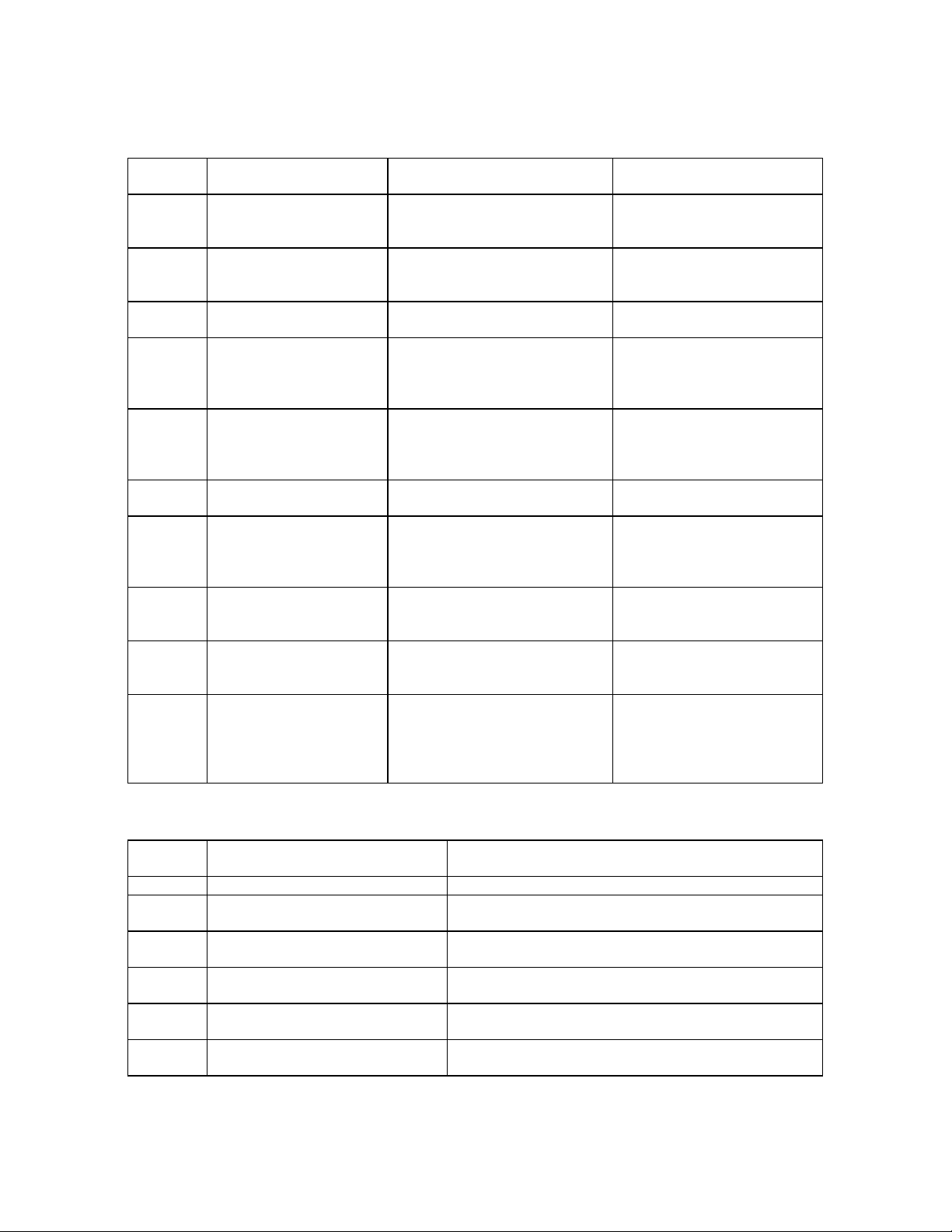
pertain to this calibration are listed in table 1.
Table 1. Calibration Description
Test instrument parameters Performance specifications
Output frequency range Continuously adjustable from 10 Hz to 110 kHz in 4
decade ranges with 10% overlap
Frequency accuracy ±2% of setting
Error measurement range ±0.3% and ±0.3% with zero center dial
Error measurement accuracy ±0.51% of FS
Distortion and noise (0.05% of setting + 10 µ V)
See footnote at end of table.
CHANGE 6 2
Page 7

TB 9-4931-700-50
Table 1. Calibration Description - Continued.
Test Instrument Parameters Performance Specifications
Line regulation ±0.001% of setting change in output voltage for a 10%
change in line voltage (included in accuracy
specifications)
Voltage stability 1 mV to 100 V: short term; ±0.002% of setting for 24
hrs. 1000 V: short term; ±0.005% of setting for 24
hrs
50 Hz to 20
kHz
1 -mV 10-mV, and 100-mV
ranges
50 Hz to 20
Output
voltage
50 Hz to 20
1
Combined accuracy and load regulation.
1-V, 10-V, and 100-V ranges 20 to 50 Hz
1000-V range
20 to 50 Hz
and
20 to 110 kHz
10 to 20 Hz
kHz
and
20 to 110 kHz
10 to 20 Hz
kHz
20 to 50 Hz
and
20 to 50 kHz
10 to 20 Hz
50 to 110 kHz
±(0.04% of setting +0.002% of range
+ 10µ V)1
±(0.07% of setting +0.005% of range
+50µ V)
±(0.22% of setting +0.005% of range
+50µ V)
±(0.032% of setting +0.002% of
range +10µ V)
±(0.062% of setting +0.005% of
range +50µ V)
±(0.212% of setting +0.005% of
range +50µ V)
±0.04% of setting
±0.08% of setting
±(0.2% of setting +0.005% of range)
±0.15% of setting
SECTION II
EQUIPMENT REQUIREMENTS
4. Equipment Required. Table 2 identifies the specific equipment used in this
calibration procedure. This equipment is issued with Secondary Reference Standards
Calibration Set NSN 4931-00-621-7878 and is to be used in performing this procedure.
Alternate items may be used by the calibrating activity when the equipment listed in
table 2 is not available. The items selected must be verified to perform satisfactorily
prior to use and must bear evidence of current calibration. The equipment must meet or
exceed the minimum use specifications listed in table 2. The accuracies listed in table 2
provide a four-to-one ratio between the standa rd and TI
5. Accessories Required. The accessories listed in table 3 are issued as indicated in
paragraph 4 above and are to be used in this calibration procedure. When necessary,
these items may be substituted by equivalent items unless specifically prohibited.
3
Page 8
TB 9-4931-700-50
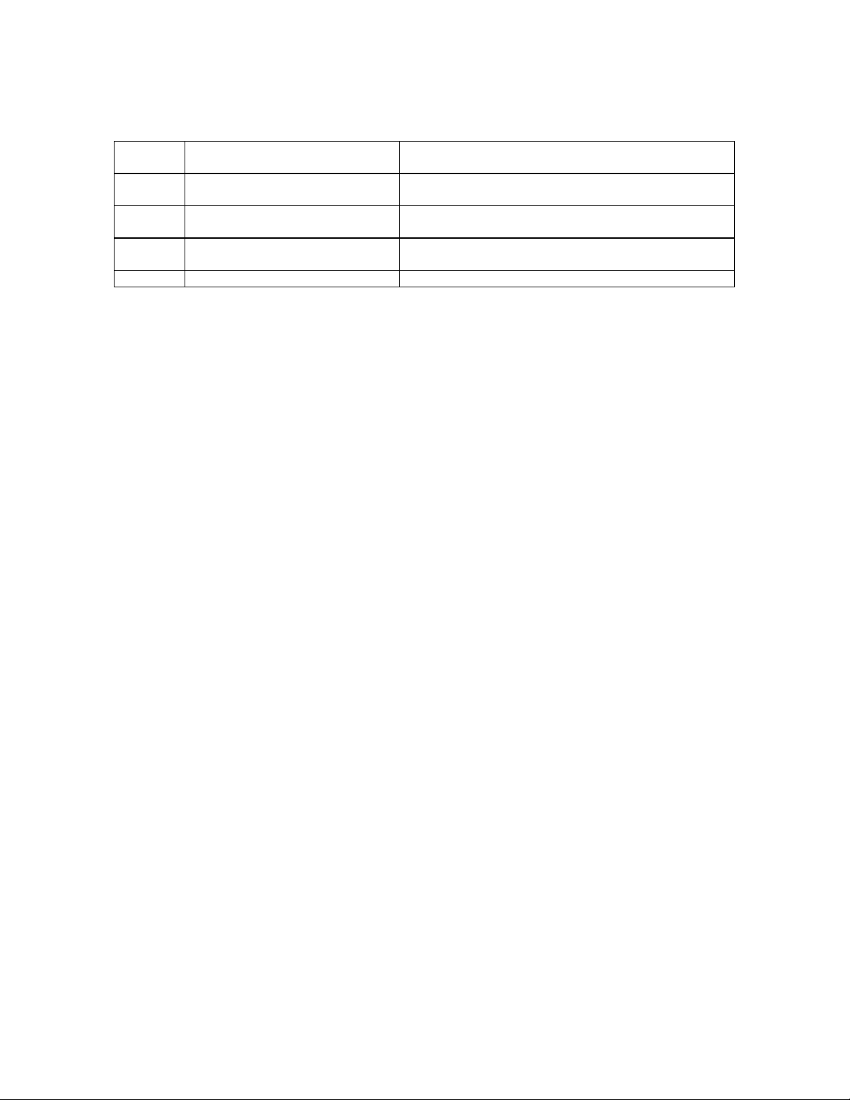
Table 2. Minimum Specifications of Equipment Required
Item
A1 AC/DC VOLTMETER
A2 AUTOTRANSFORMER
A3 DECADE RESISTOR Range: 22 to 3010 ohms Biddle Gray, Model 601147-1
A4 DISTORTION
A5 FREQUENCY
A6 LOAD (CALIBRATOR
A7 OSCILLOSCOPE Sensitivity: 0.01 to 20 V/cm
A8 RATION
A9 THERMAL TRANSFER
A10 VARIABLE
1
Combined accuracy of A1 and A9: ±0.0087%.
Common Name
(DIFFERENTIAL
VOLTMETER)
(VARIABLE POWER
TRANSFORMER)
ANALYZER
(SPECTRUM
ANALYZER)
COUNTER
(ELECTRONIC
DIGITAL COUNTER)
LOAD)
TRANSFORMER (AC
RATIO STANDARD)
STANDARD
CAPACITOR
(VARIABLE
CAPACITANCE
STANDARD)
Item
B1 ADAPTER (POWER ADAPTER) 2 to 2-wire isolation plug (7912356)
B2 ADAPTER (ELECTRICAL PLUG
CONNECTOR)
B3 ADAPTER (CONNECTOR
ADAPTER)
B4 ADAPTER (TIP JACK
ASSEMBLY)
B5 CABLE (RF CABLE ASSEMBLY) 30-in., RG -58( )/U with BNC plug terminations
B6 CABLE (RF CABLE ASSEMBLY) 36-in., RG -58( )/U with BNC plug to alligator clips
Common Name
(Official Nomenclature)
Minimum Use
Specifications
Range: 0.002 to 1850 V dc
Accuracy: 1
Capability: Use as null detector
Range: 105 to 125 V ac
Accuracy: ±1%
Range: 10 Hz to 100 kHz
Accuracy: Measure less than
.06% (Must have amplifier
capability)
Range: 9.8 Hz to 119 kHz
Accuracy: ±0.5%
Range: 2200 ohms
Accuracy: ±5%
Sweeptime: 2 ms to 10 ms/cm
Capability: Divide to 7 places
Accuracy: ±0.0085%
Range: 1 to 100 V dc 1 to 100 V
ac
Accuracy: 1
Range: 100 and 200 pF General Radio, Model 1422D
Table 3. Accessories Required
(Part Number)
Double banana plug to BNC jack terminations
(7907592)
Double banana jack to phone plug adapter (7907566)
GR plug to binding posts 874Q2 (874Q2)
(7907467)
(7909410)
Manufacturer and Model
(Part Number)
John Fluke, Models
887ABAN (887 ABAN) and
80E10 (80E10)
General Radio, Model
W10MT3AS3 (7910809)
(7910328)
Hewlett-Packard, Model
334A (7911957)
Systron-Donner, Model
1037M (7910823) w/Timer
Interval Unit, Model 1926A
(7910824)
MIRCOM, Model SKA-4850-
101
Tektronix, Model RM561A
(7910655-2) w/3A6 plug-in
(7911441-1) and 3B4
(7912040-1)
Gertsch, Model 1000
(7907060-1)
Ballantine Laboratories,
Model 1600A (MIS-10554-
2)
(8579475)
Description
4
Page 9

B7 CABLE1 (RF CABLE
ASSEMBLY)
TB 9-4931-700-50
30-in., RG -58( )/U with double banana plug
terminations (7907470)
5
Page 10
TB 9-4931-700-50
Table 3. Accessories Required - Continued.
Item
B8 CABLE (TEST LEAD) 36-in., RG -58( )/U with BNC plug and double banana
B9 HOOK-UP WIRE (ELECTRICAL
POWER CABLE)
B10 ISOLATION BOX (ADAPTER
BOX)
B11 PROBE Tektronix, Type 010-0128-00 (010-0128-00)
1
Three required.
Common Name
(Official Nomenclature)
Description (Part Number)
plug terminations (7907471)
Shielded pair No. 18 AWG, solid copper (MIS-10312)
Double banana jack terminals (SKD4850-3)
SECTION III
PRELIMINARY OPERATIO NS
6. Preliminary Instructions
a. The instructions outlined in this section are preparatory to the calibration
process. Personnel should become familiar with the entire procedure before beginning
the calibration.
b. Items of equipment used in this procedure are referenced within the text by
common name and item identification number as listed in tables 2 and 3. For the
identification of equipment referenced by item numbers prefixed with A, see table 2, and
for prefix B, see table 3.
WARNING
HIGH VOLTAGE is used during the performance of this
calibration. DEATH ON CONTACT may result if personnel
fail to observe safety precautions.
NOTE
Unless otherwise specified, verify the results of each test
and, whenever the test requirement is not met, take
corrective action before continuing with the calibration.
Adjustments required to calibrate the TI are included in this
procedure. Additional maintenance information is contained
in the manufacturer's manual, TM 9-4931-700-14/1, and TM 94931-700-14-2 for this TI.
NOTE
Unless otherwise specified, all controls and control settings
refer to the TI.
6
Page 11

TB 9-4931-700-50
7. Equipment Setup
a. Connect TI to autotransformer (A2).
b. Connect autotransformer to 115-volt ac (alternating current) and adjust its output
control to obtain a 115-volt output.
c. Set LINE switches to ON and allow 1 hour for equipment to warm-up and
stabilize.
SECTION III
CALIBRATION PROCESS
NOTE
When indications specified in paragraphs 8, 9, 10, or 12 are
not within tolerance, perform the power supply check in
paragraph 13 prior to making adjustments. After
adjustments are made, repeat paragraphs 8, 9, 10, and 12. If
indications specified in paragraph 11 are not within
tolerance, the power supply check in paragraph 14 prior to
making adjustments. Do not perform power supply checks if
all other parameters are within tolerance.
8. Frequency Accuracy
a. Performance Check
(1) Connect TI front panel output to input of frequency counter (A5), using cable
(B8).
(2) Position TI controls as listed in (a) through (d) below:
(a) Press FREQUENCY RANGE X10 pushbutton.
(b) Adjust FREQUENCY control to obtain FREQ scale indication of 1.
(c) Press VOLTAGE RANGE 1V pushbutton.
(d) Set voltage controls to obtain indication of 1.000000 V.
(3) If frequency counter does not indicate between 98.0392 and 102.041 ins
(milliseconds), perform b below.
(4) Repeat technique of (2) and (3) above , using settings and indications listed in
table 4
7
Page 12
TB 9-4931-700-50
Test Instrument Frequency Counter Indications
Frequency FREQUENCY RANGE
Settings Switch Setting Minimum Maximum
2 49.0196 ms 51.0204 ms
3 32.6797 ms 34.0136 ms
5 X10 19.6078 ms 20.4082 ms
7 14.0056 ms 14.5773 ms
10 9.8039 ms 10.2041 ms
1 9.80392 ms 10.2041 ms
2 4.90196 ms 5.10204 ms
3 X100 3.26797 ms 3.40136 ms
5 1.96078 ms 2.04082 ms
7 1.40056 ms 1.45773 ms
10 980 Hz 1020 Hz
1 980 Hz 1020 Hz
2 1960 Hz 2040 Hz
3 X1K 2940 Hz 3060 Hz
5 4900 Hz 5100 Hz
7 6860 Hz 7140 Hz
10 9.8 kHz 10.2 kHz
1 9.8 kHz 10.2 kHz
2 19.6 kHz 20.4 kHz
3 X10K 29.4 kHz 30.6 kHz
5 49.0 kHz 51.0 kHz
7 68.6 kHz 71.4 kHz
10 98.0 kHz 102.0 kHz
b. Adjustments
Table 4. Frequency Accuracy
(1) Press FREQUENCY RANGE X10K pushbutton and adjust FREQUENCY
control for FREQ scale indication of 1.0.
(2) Adjust A12C2 (fig. 1) to obtain indication of 10.000 kHz (kilohertz) on
frequency counter (R).
(3) Adjust FREQUENCY control slowly clockwise while observing frequency
counter indication. If frequency increases, proceed to b(6) below. If frequency
decreases, proceed to b(4) below.
(4) Repeat (1) above.
(5) While observing frequency counter indication, adjust A12C2 (fig. 1) to obtain a
second 10 kHz output frequency (R). If a second 10 kHz cannot be obtained by adjusting
A12C2, readjust A12C2 to obtain original 10 kHz frequency. While observing frequency
counter indication, adjust A12L1 (fig. 1) in direction that causes output to decrease and
pass through 0 (zero) Hz (hertz) and increase to 10 kHz. Adjust A12L1 to obtain
indication of 10.000 kHz on frequency counter (R).
8
Page 13

TB 9-4931-700-50
Figure 1. Model 745A bottom view - adjustment location.
9
Page 14

TB 9-4931-700-50
(6) Adjust FREQUENCY control to obtain FREQ scale indication of 10.0. Record
frequency counter indication.
(7) Refer to table 5 frequency counter indication column and locate frequency
nearest to one recorded in (6) above. Record corresponding frequency in the adjoining
column.
Table 5. FREQUENCY Scale Tracking
Frequency Counter Indication Set A12l1 (fig. 1) to Obtain
(kHz) (kHz)
80 150
81 147
82 144
83 142
84 139
85 137
86 134
87 131
88 129
89 126
90 124
91 121
92 119
93 117
94 114
95 112
96 109
97 107
98 104.6
99 102.3
100 100
101 97.69
102 95.41
103 93.2
104 90.9
105 88.7
106 86.4
107 84.1
108 82.1
109 79.9
110 77.8
111 75.6
112 73.5
113 71.4
114 69.3
115 67.2
116 65.1
117 63.1
118 61.0
119 59.0
10
Page 15

TB 9-4931-700-50
(8) Adjust A12L1 (fig. 1) to obtain frequency recorded in (7) above.
(9) Adjust FREQUENCY control counterclockwise to obtain FREQ scale
indication of 10 kHz while observing frequency counter to insure that indication does not
pass through 0 (zero) Hz. If output frequency passes through 0 (zero) Hz, repeat (2)
through (8) above.
(10) Adjust FREQUENCY control to obtain scale indication of 1.0. Adjust A12C2
to obtain indication of 10.00 kHz on frequency counter.
(11) Repeat (6) through (10) above until frequency counter indications are within
tolerance at frequency settings of 10 and 100 kHz.
(12) Repeat a(2) through (4) above and if lower frequency ranges (X10) through
X1K) are still out of tolerance, perform (a) through (t) below.
(a) Extend circuit board A12A2 (fig. 1), using extender board furnished with
TI.
(b) Connect oscilloscope (A7) to A12A2TP1 (fig. 1), using probe (B11).
(c) Adjust A12A2T1 (fig. 1) to obtain maximum amplitude of ac signal
displayed on oscilloscope (R).
(d) Press FREQUENCY RANGE X10K pushbutton and adjust FREQUENCY
control to obtain FREQ scale indication of 1.0.
(e) Connect oscilloscope to A12A2TP2 (fig. 1), using probe.
(f) Adjust A12A2C11 and A12A2C18 (fig. 1) to obtain maximum amplitude of
ac signal displayed on oscilloscope (R).
(g) Adjust FREQUENCY control to obtain FREQ scale indication of 11.0.
(h) Adjust A12A2C14 (fig. 1) to obtain maximum signal amplitude (R).
(i) Adjust FREQUENCY FREQ scale indication of 1.0.
(j) Adjust A12A2C11 (fig. 1) to obtain maximum signal amplitude.
(k) Adjust FREQUENCY FREQ scale indications of from 1.0 to 11.0. Signal
amplitude will be approximately same at both ends. Adjust A12A2C18 (fig. 1) to obtain
same amplitude at both ends.
(l) Signal at A12A2TP2 will be 0.7 volt p-p or greater at frequencies from 10
to 110 kHz.
(m) Replace circuit board A12A2 in the TI and extend circuit board A12A3
(fig. 1), using extender board.
(n) Connect oscilloscope to A12A3TP1 (fig. 1), using probe.
(o) Adjust A12A3T1 (fig. 1) to obtain maximum signal amplitude as indicated
on oscilloscope (R).
(p) Adjust FREQUENCY control to obtain FREQ scale indication of 5.5.
(q) Connect oscilloscope to A12A3TP2 (fig. 1), using probe.
(r) Adjust A12A3C11 A12A3C14, and AJ2A3C18 (fig. 1) to obtain maximum
signal amplitude indication on oscilloscope (R).
(s) Replace circuit board A12A3 in TI and extend circuit board A12A4 fig. 1
using extender board.
11
Page 16

TB 9-4931-700-50
(t) Repeat technique of (n) through (r) above for A12A4. Replace A12A4 in
TI.
(13) Repeat a(1) through (4) above.
9. Error Measurement
a. Performance Check
(1) Insert adapter (B1) between TI and autotransformer (A2) and connect
OUTPUT and SENSE terminals to ratio transformer (A8), using hook-up wire (B9).
Monitor output of ratio transformer, using ac/dc voltmeter (A1) and hook-up wire.
(2) Position TI controls as listed in (a) through (f) below:
(a) Press VOLTAGE RANGE 1V pushbutton.
(b) Set voltage controls to obtain indication of 1.000000 v
(c) Adjust FREQUENCY control to obtain FREQ scale indication of 1.
(d) Press FREQUENCY RANGE X1K pushbutton.
(e) Press ERROR RANGE 0 pushbutton.
(f) Press SENSE REMOTE pushbutton.
(3) Set ratio transformer dials to 1.000000 and record ac/dc voltmeter indication.
(4) Press ERROR RANGE X1 pushbutton and adjust ERROR MEASUREMENT
control to obtain an indication of 0 (zero) on % ERROR scale. If ac/dc voltmeter does not
indicate within ±0.00017 V of value recorded in (3) above, perform b below.
(5) Repeat technique of (3) and (4) above, using setting and indications listed in
table 6.
Table 6. Error Measurement
Test Instrument
ERROR RANGE % ERROR Ration Transformer Ac/dc Voltmeter
Setting Scale Setting Setting Indication (V)
X1 -3 .970874 Value of 9a(3) above ±0.00017
X1 -2 .980392 Value of 9a(3) above ±0.00017
X1 -1 .990099 Value of 9a(3) above ±0.00017
X1 01 1.000000 Value of 9a(3) above ±0.00017
X1 +3 1.030929 Value of 9a(3) above ±0.00017
X1 +2 1.020408 Value of 9a(3) above ±0.00017
X1 +1 1.010101 Value of 9a(3) above ±0.00017
X.1 01 1.000000
X.1 -3 .997009
1
Establish a new 1-volt reference as in 9a(3) above.
X.1 +3 1.003009
Value of 9a(3) above ±0.000035
Value of 9a(3) above ±0.000035
Value of 9a(3) above ±0.000035
b. Adjustments
(1) Set A1A4S1 (fig. 2) to +9.9 V position.
NOTE
Overload lamp illuminates.
12
Page 17

TB 9-4931-700-50
(2) Connect ac/dc voltmeter to A1A3TP5 (fig. 2), using cable (B6) and adapter
(B2).
(3) Press ERROR RANGE 0 pushbutton and adjust ERROR MEASUREMENT
control to obtain indication of 0 (zero) on % ERROR scale. Record ac/dc voltmeter
indication.
(4) Press ERROR RANGE X1 pushbutton. Loosen two setscrews that fasten the
drive sprocket to shaft of error potentiometer (fig. 1).
(5) Using a pair of long-nose pliers, rotate shaft of error potentiometer until ac/dc
voltmeter indicates exact value recorded in (3) above.
(6) While holding shaft of the error potentiometer in place, adjust ERROR
MEASUREMENT control to obtain exact 0 (zero) on % ERROR scale and tighten two
setscrews.
(7) Repeat adjustments as necessary to obtain optimum operation.
(8) Set A1A4S1 (fig. 2) to center position.
13
Page 18

TB 9-4931-700-50
Figure 2. Model 745A top view - adjustment location.
14
Page 19

Page 20

TB 9-4931-700-50
10. Voltage Accuracy, Regulation, and Frequency Response (Model 745A)
a. Performance Check
(1) Connect equipment as shown in figure 3. Remove isolation (B1) from between
TI and autotransformer.
Figure 3. Output voltage - equipment setup.
(2) Position TI controls as listed in (a) through (f) below:
(a) Press VOLTAGE RANGE 1V pushbutton..
(b) Set voltage controls to obtain an indication of 1.000000 V.
(c) Press FREQUENCY RANGE X1K pushbutton.
(d) Adjust FREQUENCY control to obtain FREQ scale indication of 1.0.
(e) Press ERROR RANGE 0 pushbutton.
(f) Press SENSE REMOTE pushbutton.
14 CHANGE 6
Page 21

TB 9-4931-700-50
NOTE
Each time measurement of TI output is directed, a minimum
of four readings should be taken. The first reading should be
disregarded and the other three readings averaged. The
average reading is the indication to be recorded for future
use. The ac/dc voltmeter (A1) indication should be read
between 15 and 20 seconds after thermal transfer standard
(A9) transfers to the dc output.
(3) Measure TI output, using thermal transfer standard in auto mode. Record
ac/dc Voltmeter indication.
(4) Compute and record difference between the indication recorded in (3) above
and TI voltage controls setting. If indication in (3) is large a + (plus) sign is assigned to
difference. If it is smaller, a - (minus) sign is assigned to difference. Convert difference
to percentage retaining assigned sign.
(5) Refer to test report for thermal transfer standard to obtain percentage of
ac/dc difference for 1 V at appropriate frequency.
(6) Add algebraically two percentages obtained in (4) and (5) above. The result is
percentage of TI output error. If TI output error is ±0.035 percent or more, perform b(1)
through (3) below.
(7) Repeat technique of (1) through (6) above with autotransformer (A2) set at 105
and 125 V ac. If error does not remain within ±0.035 percent and adjustments were not
performed in (6) above, perform b(1) through (3) below and repeat (2) through (6) above.
Return autotransformer setting to 115 V ac.
(8) With decade resistor (A3) set to 22 ohms, connect at input to thermal transfer
standard, using cable (B7).
(9) Repeat technique of (1) through (6) above. The TI output will remain within
specified limits.
(10) Perform technique of (1) through (6), (8), and (9) above, using settings and
indications listed in table 7.
(11) Disconnect decade resistor.
(12) Set TI frequency to 1 kHz and voltage range to 1 V.
(13) With thermal transfer standard in manual balance mode and dc output state,
adjust its manual balance controls to obtain an ac/dc voltmeter indication of 1.000000 V
dc.
15
Page 22

TB 9-4931-700-50
Table 7. Frequency Response
Test Instrument
Voltage Acceptable Decade resistor
Output Error (Percent) Setting (Ohms) Adjustments
Frequency (V) (Step a(6)) (Step a(8))
10 Hz 1 ±0.22% 22
100 Hz 1 ±0.035% 22 If an out-of-tolerance condition is
indicated for any
10 kHz 1 ±0.035% 22 frequency on the 1 V range, perform
10b(1)
20 kHz 1 ±0.035% 22 through (3) below and repeat all checks
on 1 V
50 kHz 1 ±0.072% 22 range.
100 kHz 1 ±0.072% 22
10 Hz 101 ±0.22% 221
100 Hz 10 ±0.034% 221
1 kHz 10 ±0.034% 221 If an out-of-tolerance condition is
indicated for any
10 kHz 10 ±0.034% 221 frequency on the 10 V range, perform
10b(1),
20 kHz 10 ±0.034% 221 (2), and (4) below and repeat all checks
on 10 V
50 kHz 10 ±0.068% 221 range.
100 kHz 10 ±0.068% 221
10 Hz 1001 ±0.22% 22002 If an out-of-tolerance condition is
indicated for 10
100 Hz 100 ±0.034% 2200 Hz, or 1 kHz on the 100 V range,
perform
1 kHz 100 ±0.034% 2200 10b(2), (5), and (6) below and repeat all
previous checks on 100 V range.
10 kHz 100 ±0.034% 2200
20 kHz 100 ±0.034% 2200 If an out-of-tolerance condition is
indicated for 10,
50 kHz 100 ±0.067% 2200 20, 50, or 100 kHz on the 100 V range,
perform
100 kHz 100 ±0.067% 2200 10b(2), (5), and (7) below , and repeat
1
Repeat technique of (7) above.
2
Replace decade resistor (A3) with load (A6) for remaining checks.
all checks on 100 V range.
(14) Set thermal transfer standard to ac balancing state. Adjust TI voltage
controls to obtain null indication on thermal transfer standard meter with its null X5
pushbutton pressed.. Record TI voltage control indication.
(15) Repeat (13) and (14) above twice. Average the three voltage control
indications. If average indication is 1.0 or more, subtract 1.0 from it and assign a (minus) sign. If it is less than 1.0, subtract it from 1.0 and assign a + (plus) sign. Record
value.
(16) Refer to test report for thermal transfer standard to obtain percentage of
ac/dc difference for 1 V at 1 kHz. Convert percentage to voltage error, retaining sign.
Record value.
16
Page 23

TB 9-4931-700-50
(17) Add algebraically values recorded in (15) and (16) above. Reverse sign and
add to 1.0. Record this value. This is the correct TI voltage control setting to obtain 1 V
output.
(18) Connect equipment as shown in figure 4.
Figure 4. Low voltage - equipment setup.
(19) Position TI controls as listed in (a) through (c) below:
(a) Press VOLTAGE RANGE 1 mV pushbutton.
(b) Set voltage controls to obtain indication of 1.000000 mv.
(c) Press FREQUENCY RANGE X1 K pushbutton.
(20) Set ratio transformer (A8) dials to 1.000000.
NOTE
In following checks, distortion analyzer (A4) is utilized as an
amplifier only.
(21) Set distortion analyzer to voltmeter function and 1 mV (millivolt) range.
(22) Adjust ac/dc voltmeter (A1) dials to obtain null indication. Leave voltage
readout dials set.
17
Page 24

TB 9-4931-700-50
(23) Set ratio transformer dials to .001000.
(24) Position TI controls as listed in (a) through (c) below:
(a) Press VOLTAGE RANGE 1V pushbutton.
(b) Set voltage controls to obtain same indication recorded in (17) above.
(c) Press ERROR RANGE X1 pushbutton.
(25) Adjust ERROR MEASUREMENT control to obtain a null indication on ac/dc
voltmeter. % ERROR scale will indicate within ±1.04 percent.
(26) Position TI controls as listed in (a) through (c) below:
(a) Press VOLTAGE RANGE 10 mV pushbutton.
(b) Set voltage controls to obtain indication of 10.00000 mv.
(c) Press ERROR RANGE 0 pushbutton.
(27) Set distortion analyzer range to 10 mV.
(28) Set ratio transformer dials to 1.000000.
(29) Adjust ac/dc voltmeter dials to obtain null indication. Leave voltage readout
dials set.
(30) Set ratio transformer dials to .010000.
(31) Position TI controls as listed in (a) through (c) below:
(a) Press VOLTAGE RANGE 1V pushbutton.
(b) Set voltage controls to obtain same indication recorded in (17) above.
(c) Press ERROR RANGE X.1 pushbutton.
(32) Adjust ERROR MEASUREMENT control to obtain a null indication on ac/dc
voltmeter. The % ERROR scale will indicate within ±0.142 percent.
18
Page 25

TB 9-4931-700-50
(33) Position TI controls as listed in (a) through (c) below:
(a) Press VOLTAGE RANGE 100mV pushbutton.
(b) Set voltage controls to obtain indication of 100.0000 mv.
(c) Press ERROR RANGE 0 pushbutton.
(34) Set distortion analyzer range to 100 mV.
(35) Set ratio transformer dials to 1.000000.
(36) Adjust ac/dc voltmeter dials to obtain a null indication. Leave voltage readout
dials set.
(37) Set ratio transformer dials to .100000.
(38) Position TI controls as listed in (a) through (c) below:
(a) Press VOLTAGE RANGE 1V pushbutton.
(b) Set voltage controls to obtain same indication recorded in (17) above.
(c) Press ERROR RANGE X.1 pushbutton.
(39) Adjust ERROR MEASUREMENT control to obtain null indication on ac/dc
voltmeter. The % ERROR scale will indicate within ±0.052 percent.
(40) Set decade resistor dials to 3010 ohms and connect across TI OUTPUT
terminals, using cable (B7).
(41) Repeat (33) through (39) above.
b. Adjustments
NOTE
Perform power supply check in paragraph 13 prior to making
adjustments.
(1) Press FREQUENCY RANGE X10K pushbutton and adjust FREQUENCY
control to obtain FREQ scale indication of 10.
(2) With thermal transfer standard in manual balance mode and dc output state,
adjust its manual balance controls to obtain ac/dc voltmeter indication equal to the value
of TI voltage controls setting.
(3) Set thermal transfer standard to ac balancing state. Adjust TI A3C12 (fig. 2)
to obtain null indication on thermal transfer standard meter with its null X5 pushbutton
pressed (R).
(4) Set thermal transfer standard to ac balancing state. Adjust TI A6R16 (fig. 2)
to obtain null indication on thermal transfer standard meter with its null X5 pushbutton
pressed (R).
(5) Press FREQUENCY RANGE X1K pushbutton and adjust FREQUENCY
control to obtain FREQ scale indication of 10.
(6) Set thermal transfer standard to ac balancing state. Adjust TI A14R7 (fig. 2)
to obtain null indication on thermal transfer standard meter with its null X5 pushbutton
pressed (R).
19
Page 26

TB 9-4931-700-50
(7) Set thermal transfer standard to ac balancing state. Adjust TI C9 (fig. 2) to
obtain null indication on thermal transfer standard meter with its null X5 pushbutton
pressed (R).
11. Voltage Accuracy, Regulation, and Frequency Response (Model 746A)
a. Performance Check
(1) Connect equipment as shown in figure 5.
Figure 5. High - equipment setup.
(2) Position TI controls as listed in (a) through (f) below:
(a) Press VOLTAGE RANGE 1000 V ext. pushbutton.
(b) Set voltage controls to obtain an indication of 100.000 V.
(c) Press FREQUENCY RANGE X1K pushbutton.
(d) Adjust FREQUENCY control to obtain FREQ scale indication of 1.0
(e) Press ERROR RANGE 0 pushbutton.
(f) Press OUTPUT ON pushbutton.
NOTE
Each time measurement of TI output is directed, a minimum
of four readings should be taken. The first reading should be
disregarded and the other three readings averaged. The
average reading is the indication to be recorded for future
use. The ac/dc voltmeter (A1) indication should be read
between 15 and 20 seconds after thermal transfer standard
(A9) transfers to the dc output state.
20
Page 27

TB 9-4931-700-50
(3) Measure TI output, using thermal transfer standard in auto mode. Wait
approximately 2 minutes after applying ac voltage before transferring to the dc output
state. Record ac/dc voltmeter indication. -
(4) Compute and record difference between indication recorded in (3) above and
TI voltage controls setting. If indication in (3) is larger, a + (plus) sign is to difference. If
it is smaller, a - (minus) sign is assigned to difference. Convert difference to percentage
retaining assigned sign.
(5) Refer to test report for thermal transfer standard to obtain percentage of
ac/dc difference for 100 V at appropriate frequency.
(6) Add algebraically two percentages obtained in (4) and (5) above. The result is
percentage of TI output error. If TI output error is more than ±0.04 percent, perform b
below.
(7) Repeat technique of (2) through (6) above with autotransformer set at 105 and
125 V ac. If error does not remain within ±0.04 percent and adjustments were not
performed in (6) above, perform b below and repeat (2) through (6) above. Return
autotransformer setting to 115 V ac.
(8) Repeat technique of (7) above with voltage controls set to o btain an indication
of 1000.000 V.
(9) Perform technique of (3) through (6) above, using frequencies and acceptable
errors listed in table 8.
Table 8. Accuracy and Frequency Response
Test Instrument Frequency Acceptable Error (Percent)
50 Hz ±0.04
100 Hz ±0.04
10 kHz ±0.04
20 kHz ±0.04
50 kHz ±0.08
100 kHz ±0.15
(10) Press OUTPUT OFF pushbutton.
(11) Connect variable capacitor (A10) across TI output (connect to adapter B4
using both conductors of a pair for each connection, hook-up wire B9). Set variable
capacitor dial to 125 pF (picofarad).
(12) Set voltage controls to obtain an indication of 700.000 V and press OUTPUT
ON pushbutton.
(13) Repeat (9) above.
(14) Press OUTPUT OFF pushbutton.
(15) Replace variable capacitor with decade resistor (A3). Set variable resistor
dials to 16000 ohms.
(16) Set voltage controls to obtain an indication of 100.000 V.
(17) Press FREQUENCY( RANGE )(10 pushbutton and adjust FREQUENCY
control to obtain FREQ SCALE indication of 1.0.
21
Page 28

TB 9-4931-700-50
(18) Press OUTPUT ON pushbutton.
(19) Repeat technique of (3) through (6) above. The TI output error will not be
more than ±0.25 percent.
(20) Press OUTPUT OFF pushbutton.
b. Adjustments
NOTE
Perform power supply check in paragraph 14 below prior to
making adjustments.
22
Page 29

TB 9-4931-700-50
NOTE
Perform (1) through (6) below and repeat a above. If still outof-tolerance, perform (7) through (26) below.
(1) With thermal transfer standard in manual balance mode and dc output state,
adjust its manual balance controls to obtain ac/dc voltmeter indication equal to value of
TI voltage control setting.
WARNING
Do not adjust R5 or L3 with instruments floating above earth
ground. Mounting hardware for R5 and L3 is at circuit
ground.
(2) Set thermal transfer standard to ac balancing state. Adjust R5 (fig. 6) to
obtain null indication on thermal transfer standard meter X pushbutton pressed (R).
Figure 6. Model 746A top view - Adjustment locations.
(3) Press FREQUENCY RANGE X10K pushbutton and adjust FREQUENCY
control to obtain FREQ scale indication of 10.0.
(4) Repeat (1) above.
(5) Set thermal transfer standard to ac balancing state. Adjust L3 (fig. 6) to
obtain null indication on thermal transfer standard meter with its null X5 pushbutton
pressed (R).
(6) Press OUTPUT OFF pushbutton.
23
Page 30

TB 9-4931-700-50
(7) Remove bottom cover from TI (model 746A only). Remove plastic cover from
A6 amplifier assembly (fig. 7).
Figure 7. Model 746A bottom view - adjustment location.
(8) Connect ac/dc voltmeter high voltage leads between test point B (fig. 7) and
GND (circuit ground).
(9) Press OUTPUT ON pushbutton.
NOTE
The voltages in (10) and (12) below do not have to be exact.
They may vary as much as ±50 V. The important point is that
voltage difference between them is 30 ±2 V.
(10) Adjust A6R14 (fig. 7) to obtain indication of 1850 V dc on ac/dc voltmeter (R).
(11) Move ac/dc voltmeter leads to test point A6TP6 (fig. 7) and GND (circuit
ground).
(12) Adjust A6R77 (fig. 7) to obtain indication of 1820 V dc on ac/dc voltmeter (R).
(13) Press OUTPUT OFF pushbutton.
24
Page 31

TB 9-4931-700-50
(14) Connect variable capacitor across TI output (connect at isolation box, using
cable). Set variable capacitor dial to 50 pF.
(15) Connect oscilloscope (A7) to A6TP2 (fig. 7), using probe (B11).
(16) Position TI controls as listed in (a) through (d) below:
(a) FREQUENCY RANGE X10K pushbutton pressed.
(b) FREQUENCY control to obtain FREQ scale indication of 101.
(c) Voltage controls to obtain indication of 100.000 V.
(d) OUTPUT ON pushbutton pressed.
(17) Adjust (increase) TI output in 100 V steps to 700 V or until a glitch appears on
waveform as shown in figure 8.
Figure 8. Waveform at A6TP2.
(18) If no glitch appears, adjust (increase) capacitance of variable capacitor until it
does appear. After glitch appears, adjust A6C18 (fig. 7) until waveform becomes clear
and then another glitch appears. Note range of A6C18 between points where glitches
appear.
(19) Adjust (increase) capacitance of variable capacitor and adjust A6Cl8 until
range as noted in (15) above is minimum (R).
(20) Connect ac/dc voltmeter to A6TP6 (fig. 7) (same as V3 RED) and circuit
ground, using leads supplied with ac/dc voltmeter.
(21) Adjust A6R77 (fig. 7) to obtain indication of 1800 V dc on ac/dc voltmeter (R).
(22) Adjust variable capacitor for 100 pF.
(23) Adjust TI output from 700 V to 100 V. The oscilloscope will not show signs of
oscillations.
(24) Set voltage controls to obtain indication 700.000 V and adjust frequency from
110 to 10 kHz. If oscilloscope indication is not smooth with no oscillations, repeat (7)
through (20) above.
25
Page 32

TB 9-4931-700-50
(25) Set voltage controls to obtain indications of 100.000 V. Press FREQUENCY
RANGE X1K pushbutton and adjust FREQUENCY control to obtain FREQ scale
indication of 1.0.
(26) Connect ac/dc voltmeter between A6TP5 (fig. 7) and circuit ground, using
cable and adapter (B6 and B2). If ac/dc voltmeter does not indicate 10 V ac, use ERROR
RANGE pushbuttons and ERROR MEASUREMENT control to obtain 10 V ac indication.
(27) Press FREQUENCY RANGE X10K pushbutton and adjust FREQUENCY
control to obtain FREQ scale indication of 10.0.
(28) If ac/dc voltmeter does not indicate between 10.3 and 10.7 V ac, adjust A6C12
(fig. 7) to obtain indication of between 10.3 and 10.7 V ac.
12. Distortion
a. Performance Check
(1) Connect equipment as shown in figure 9.
(2) Position TI controls as listed in (a) through (f) below:
(a) Press VOLTAGE RANGE 1V pushbutton.
(b) Set voltage set controls to obtain indication of 1.000000 V.
(c) Press FREQUENCY RANGE X10 pushbutton.
(d) Adjust FREQUENCY control to obtain FREQ scale indication of 1.0.
(e) Press ERROR RANGE 0 pushbutton.
(f) Press SENSE LOCAL pushbutton.
(3) Adjust decade resistor (A3) dials to 22 ohms.
26
Page 33

TB 9-4931-700-50
Figure 9. Distortion check - equipment setup.
(4) Measure distortion. If distortion is not .06 percent or less, perform b below.
(5) Repeat (4) above for frequencies of 50 and 100 Hz, and 1, 10, 50, and 100 kHz.
If distortion is not .06 percent or less, perform b below.
(6) Repeat technique of (2) through (5) above, using settings and indications
listed in table 9.
Table 9. Distortion
Test Instrument VOLTAGE Resistance Value Maximum Distortion
RANGE Switch Settings (V) (Ohms) Allowed (Percent)
10 221 .060
1
Replace decade resistor (A3) with load (A6).
100 22001 .060
(7) Connect output of the TI (Model 746A) to input of distortion analyzer (A1).
(8) Position TI (Model 745A) controls as listed in (a) through (d) below:
(a) Press FREQUENCY RANGE X10 pushbutton.
(b) Adjust FREQUENCY control to obtain FREQ scale indication of 1.0.
(c) Press VOLTAGE RANGE 1000V ext. pushbutton.
(d) Set voltage controls to obtain 100.000 V.
(9) Press OUTPUT ON pushbutton (Model 746A).
(10) Measure distortion. Distortion will be .06 percent or less.
27
Page 34

TB 9-4931-700-50
(11) Repeat technique of (8), (9), and (10) above for frequencies of 50 Hz, and 1, 10,
50, and 100 kHz. Distortion will be .06 percent or less.
(12) Press OUTPUT OFF pushbutton.
b. Adjustments
NOTE
Deenergize TI when removing or installing circuit boards.
(1) Remove circuit board A12A5 (fig. 1) from TI and extend -circuit board A12A7
(fig. 1) using extender board supplied with TI.
(2) Press FREQUENCY RANGE X10K pushbutton and adjust FREQUENCY
control to obtain FREQ scale indication of 5.
(3) Connect oscilloscope (A7) to A12A7TP2 (fig. 1), using probe (B11) and connect
ac/dc voltmeter (A1) to A12A8TP1 (fig. 1).
(4) Center adjustments A12A7R26 and A12A7R29 (fig. 1).
(5) Adjust 112A7C14 (fig. 1) to obtain minimum amplitude of the ac signal
displayed on oscilloscope (R).
(6) Alternately adjust A12A7R26 and A12A7R29 (fig. 1) to obtain minimum
amplitude of ac signal displayed on oscilloscope.
(7) Repeat (5) and (6) above to obtain optimum indication. The amplitude of ac
signal should be less than 0.05 V p-p.
(8) Ac/dc voltmeter will indicate 0 ±2 mV dc.
(9) Adjust A12A7R26 and A12A7R29 (slightly) to obtain an ac/dc voltmeter
indication of 0 ±2 mV dc.
(10) Repeat (5) through (9) as necessary until ac signal is less than 0.05 V P-P and
dc voltage is 0 ±2 mV dc.
(11) Replace circuit boards in TI.
(12) Press FREQUENCY RANGE X1K pushbutton and adjust FREQUENCY
control to obtain FREQ scale indication of 1.
(13) Extend circuit board A12A8 (fig. 1), using extender board furnished with TI.
(14) Connect ac/dc voltmeter to A12A8TP1 (fig. 1) and adjust A12A8R32 to obtain
indication of 0.1 V ac (R).
(15) Connect ac/dc voltmeter to A2TP4 (fig. 2) and adjust A12A6R4 (fig. 1) to obtain
indication of between -.99 and 1.1 V dc (R).
(16) Connect ac/dc voltmeter to A12A8TP2 (fig. 1) and adjust A12A8R15 (fig. 1) to
obtain indication of between 0.25 and 0.35 V dc (R).
(17) Replace circuit board in TI.
13. Power Supply (Model 745A)
NOTE
28
Page 35

TB 9-4931-700-50
Do not perform power supply check if all other parameters
are within tolerance.
NOTE
In the following procedure all voltages are measured with
respect to circuit common (1). Circuit common is available at
any point on inner chassis.
a. Performance Check
(1) Set TI for output of 1.000000 mV at 1 kHz.
(2) Connect ac/dc voltmeter (A1) between A8TP3 (fig. 2) and circuit common,
using cable and adapter (B6 and B2). If ac/dc voltmeter does not indicate between -69.5
and -70.5 V dc, perform b below.
(3) Repeat technique of (1) and (2) above for settings and indications listed in
table 10. If an out-of-tolerance condition is indicated, perform specified adj ustment.
b. Adjustments. Adjust A8R30 (fig. 2) to obtain an ac/dc voltmeter indication of
-70.00 V dc (R).
29
Page 36

TB 9-4931-700-50
Table 10. Power Supply and Bias
Test Instrument Ac/dc Voltmeter, Frequency Counter, Adjustments
Connection Points or Oscilloscope (fig. 2)
(fig. 2) Indications
A8TP4 +69.50 to +70.50 V dc A8434 (R)
A8TP1 -24.80 to -25.20 V dc A8429 (R)
A8TP2 +5.10 to +5.30 V dc A8R6 (R)
A4TP1 -0.0030 to +0.0030 V dc A4R8 (R)
A3TP11 -0.0010 to +0.0010 V dc A3R34 (R)
A2 PIN 122 450 to 550 ms sample gate A3410 (R)
A25013 -0.0010 to +0.0010 V dc A2R9 (4)
A2TP24 +0.550 to +0.650 V dc A2R34 (R)
A2TP3 -0.0001 to +0.0001 V dc A2R67 (R)
A2TP45 -0.90 to -1.10 V dc - - A2TP46 Indication equal to that recorded in footnote 5
A4439 (R)
below
A1A3TP57 499 to 501 Hz A1A4R5 (R)
A1A3TP58 -9.89999 to -9.90001 V dc A1A3R32 (coarse), R34 (fine) (R)
A1A3TP59 +9.89999 to +9.90001 V dc 10 A1A3R14 (coarse), R16 (fine) (R)
1
Adjust frequency to 50 kHz and set A1A4S1 (fig. 2) to +9.9 V position. Overload lamp may illuminate, this may be
expected when A1A4S1 is switched from 19.8 V position.
2
Set A1A4S1 to 19.8 V position; connect oscilloscope (A7), using cable (B4).
3
Remove PC board A3.
4
Reinstall PC board A3 and reset frequency to 50 kHz.
5
Press FREQUENCY RANGE X1K pushbutton. Record voltage level indication.
6
Press FREQUENCY RANGE X100 pushbutton
7
Connect frequency counter (A5).
8
Set A1A4S1 to -9.9 V position.
9
Set A1A4S1 to +9.9 V position.
10
After completing check, set A1A4S1 to 19.8 V position.
14. Power Supply (Model 746A)
NOTE
Do not perform power supply check if all other . parameters
are within tolerance.
a. Performance Check
(1) Connect ac/dc voltmeter (A1) between -30 V test point (TP3) of A4 assembly
(fig. 6 and 10) and circuit ground. Ac/dc voltmeter will indicate between -29.7 and -30.3
V dc.
(2) Connect ac/dc voltmeter between +6 V test point (TP1) of A4 assembly (fig. 10)
and circuit ground. Ac/dc voltmeter will indicate between 5.94 and 6.06 V dc.
(3) Connect ac/dc voltmeter between +150 V test point (TP2) of A4 assembly (fig.
10) and circuit ground. AC/dc voltmeter will indicate between 145.5 and 154.5 V dc.
b. Adjustments. No adjustments can be made.
30
Page 37

TB 9-4931-700-50
Figure 10. A4 Assembly - test point locations.
15. Flow Procedure
a. Deenergize and disconnect all equipment and reinstall TI protective cover.
b. In accordance with TM 38-750, annotate and affix DA Label 80 (US Army
Calibrated Instrument). When the TI receives limited or special calibration, annotate
and affix DA Label 163 (US Army Limited or Sp ecial Calibration). When the TI cannot
be adjusted within tolerance, annotate and affix DA Form 2417 (US Army Calibration
System Rejected Instrument).
31
Page 38

TB 9-4931-700-50
By Order of the Secretary of the Army:
BERNARD W. ROGERS
General, United States Army
Chief Of Staff
Official:
J. C. PENNINGTON
Brigadier General, United States Army
The Adjutant General
Distribution:
To be distributed in accordance with Std. IDS No. RLC-1500, 13 March 1974.
US GOVERNMENT PRINTING OFFICE: 1984 - - 746-036/3377 REGION #4
PIN NO: 009082-000
 Loading...