

Page 1

Technical Reference Manual for OEMs
HP Models 743, 744, and 748
HP Part No. A4511-90601
Printed in USA
August, 1997
Special Online Edition 1199
Page 2

Legal Notices
Legal Notices
Manual Content
Information in this manual is subject to change without notice.
Hewlett-Packard makes no warranty of any kind about this manual, including, but not limited to, the implied warranties of merchantability and fitness for a particular purpose.
Hewlett-Packard shall not be liable for errors contained herein or direct, indirect, special,
incidental, or consequential damages about the furnishing, performance, or use of this material.
ii
Copyright © Hewlett-Packard Company 1994, 1995, 1996, 1997, 1999. This document contains information which has been protected by copyright. All rights are reserved. Reproduction, adaptation, or translation without prior written permission is prohibited, except as
allowed under the copyright laws.
Software mentioned and documentation is based in part on the Fourth Berkeley Software
Distribution under license from the Regents of the University of California.
Restricted Rights Legend
Use, duplication, or disclosure by the United States Government is subject to restrictions as
set forth in subparagraph (c) (1) (ii) of the Rights in Technical Data and Computer Software
clause at FARs 52.227.7013.
Hewlett-Packard Company
Embedded Systems Operation
3000 Minuteman Road
Andover, MA 01810
Page 3

Printing History
Printing History
The printing date and edition number shown is the current edition of this manual. The printing date changes when a new edition is printed. Minor changes may be made at reprint without changing the printing date.
August 1994, Edition 1
April 1995, Edition 2
September 1995 Edition 3
June 1996, Edition 4
December 1996, Edition 5
March 1997, Edition 6
August 1997, Edition 7
iii
Page 4

Safety Symbols and Conventions
Safety Symbols and Conventions
This manual uses the following conventi ons:
NOTE: Notes conta in important information set off from the text.
CAUTION: Caution messages indicate procedures which, if not observed, could result in damage to
equipment. Do not proceed beyond a CAUTION sign until the indicated conditions are fully
understood and met.
WARNING: Warning messages indicate procedures or practices which, if not observed, could result
in personal injury. Do not proceed beyond a WARNING sign until the indicated
conditions are fully understood and met.
iv
Page 5

Contents
1 General Information
Model 743 and Model 744 VME Board Computers 1-2
Product Description 1-2
Supported Configurations 1-7
Model 743 Memory 1-7
Model 744 Memory 1-7
System Graphics 1-8
Model 743 and Model 744 External Devices 1-9
Keyboard and Mouse 1-9
Model 743 and Model 744 Cables 1-9
Model 743 and Mod e l 744 Functional Descript ion 1-11
Model 744 Bloc k Diagram 1-14
CPU Circuit 1-15
Boot ROM Circuit 1 -16
Graphics Circuit 1-16
Model 743 Memory Controller Circuit 1-17
Model 744 Memory Controller Circuit 1-17
LED Displays 1-18
I/O Controller ASIC 1-1 8
VME Controller ASIC 1-23
I/O Expansion 1-25
I/O Expansion Bloc k Diagrams 1-26
1-6
Model 748 Ruggedized Workstation 1-27
Product Description 1-27
Supported Configurations 1-27
Model 748 Ruggedized Workstation Functional Desc ription 1-30
Environmental Specifications for Monitors 1-31
Original Equipment Manufacturer (OEM) Support Overview 1-32
Standard Support 1-32
Additional OEM Support Programs 1-32
2 References
HP Hardware Manuals 2-2
Contents-1
Page 6

Contents
Installation Guides 2-2
Service Manuals 2-2
Diagnostic Manuals 2-3
HP Software Manuals 2-4
3 Quality
Safety Compliance Programs 3-2
Introduction 3-2
Underwriter’s Laboratories (USA) 3-2
Canadian Standards Association (Canada) 3-2
TUV Rheinland (Germany) 3-2
Electromagnetic Compatibility Progra ms 3-3
Introduction 3-3
Federal Communications Commission (USA) 3-3
European Community 3-3
Voluntary Control Council for Interference (Japan) 3-3
Overview 3-4
Electromagnetic Field Emissions Test Suite 3-4
Electromagnetic Field Immunity/Susceptibility Test Suite 3-5
Line Transients Immunity/Susceptibility Test Suite 3 -6
Climatic and Dynamic Environmental Ruggedness 3-8
Introduction 3-8
Overview 3-8
Temperature, Humidity, and Altitude Test Suite 3-9
Acoustics 3-11
Sound Power Leve ls 3-11
Statistical Reliability 3-1 2
Annualized Failure Rate Projections 3-12
Mean Time Between Failure Computations 3-12
Contents-2
Page 7

Contents
4 Mechanical Information
Model 743 and Model 744 VME Board Computers 4-2
Key Components 4-2
Air Flow Requirements 4-4
Interface Connectors 4-6
Mechanical Dimensions 4-7
Model 748 Chassis and Modules 4-20
Weights 4-27
Mounting and Support 4-28
Mechanical Drawings 4-28
Conversion Cables 4-28
Chassis Parts and Models 4-29
5 Electrical Information
Video Connector Pinouts 5-3
Audio Connector Pinouts 5-8
HP Parallel Connector Pinouts 5-10
RS-232 Connector Pinouts 5-12
AUI LAN Connector Pinouts 5-14
Single-Ended SCSI Connector Pinouts 5-16
FW SCSI Connector Pinout 5-18
PS/2 Connector Pinouts 5-20
VME Connector Pinouts 5-21
Real-Time Clock (RTC) Battery Information 5-37
Battery Specifications 5-37
Video Output Signal Specifi cations 5-37
Video Timing Specifications 5-37
6 Power Req uirements
Power Distribution 6-2
FW SCSI Estimated Power Consumption 6-6
Monitor Power Specifications 6-6
Contents-3
Page 8

Contents
Power Budgeting 6-7
7 Product Design Considerations
Application Information 7-2
VME Services Updates 7-2
VME Systems Design Considerations for Models 743, 744, and 748 7-2
System Integration 7-3
Hardware Power On Information 7-3
Contents-4
Page 9

1
General Information
The General Information Chap ter provides ge neral informa tion on the Model 743 and Model
744 VME Board Computers, the Model 748 Ruggedized Workstation, environmental specifications for the supported monitors, and OEM support.
1-1
Page 10
General Information
Model 743 and Model 744 VME Board Computers
Model 743 and Model 744 VME Board Computers
The sections that follow contain the Model 743 and Model 744 VME Board Computer product descriptions and functional descriptions.
Product Description
HP Model 744 VME Board Computers are based on the PA 7300LC CPU. HP Model 743
VME Board Computers are based on th e PA 7100LC CPU. Running either HP-UX or HP-R T
operating systems, they are typically installed in a VME backplane.
• Model 744/165L: HP-UX operating system, 165 MHz system clock
• Model 744rt/165L: HP-RT operating system, 165 MHz system clock
• Model 744/132L: HP-UX operating system, 132 MHz system clock
• Model 744rt/132L: HP-RT operating system, 132 MHz system clock
• Model 743i/64: HP-UX operating system, 64 MHz system clock
• Model 743i/100: HP-UX operating system, 100 MHz system clock
• Model 743rt/64: HP-RT oper ating system, 64 MHz system clock
• Model 743rt/100: HP-RT operating system, 100 MHz system clock
Each board computer is complete with the core I/O of an HP-PA workstation in a single-slot
VME solution with expandabi lity for more I/O or RAM in a two-slot o r three -slot VME solu tion. The core design incl udes appl icat ion-s pecif ic int egrated ci rcuit s (ASICs) that a dd VME
and real-time features.
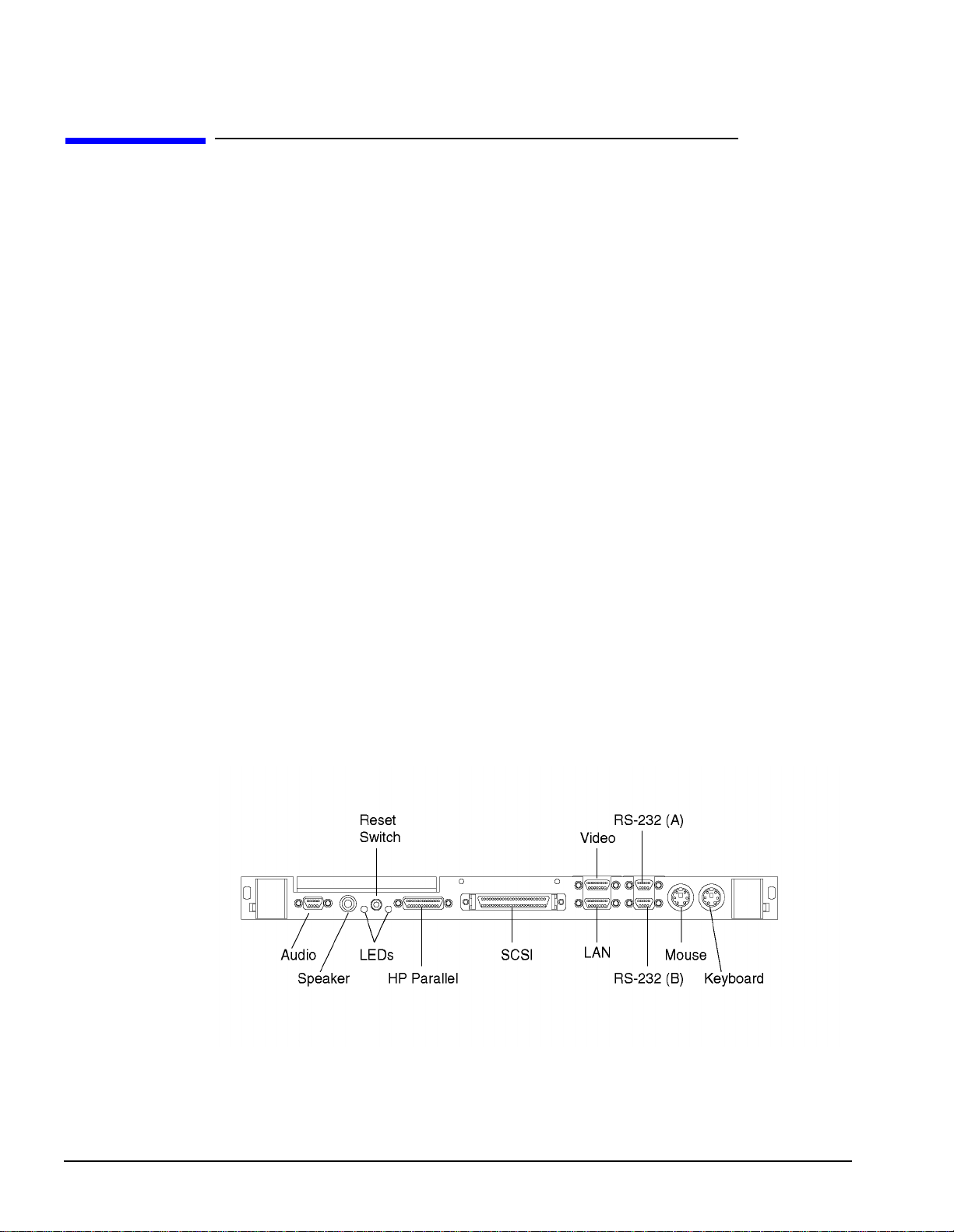
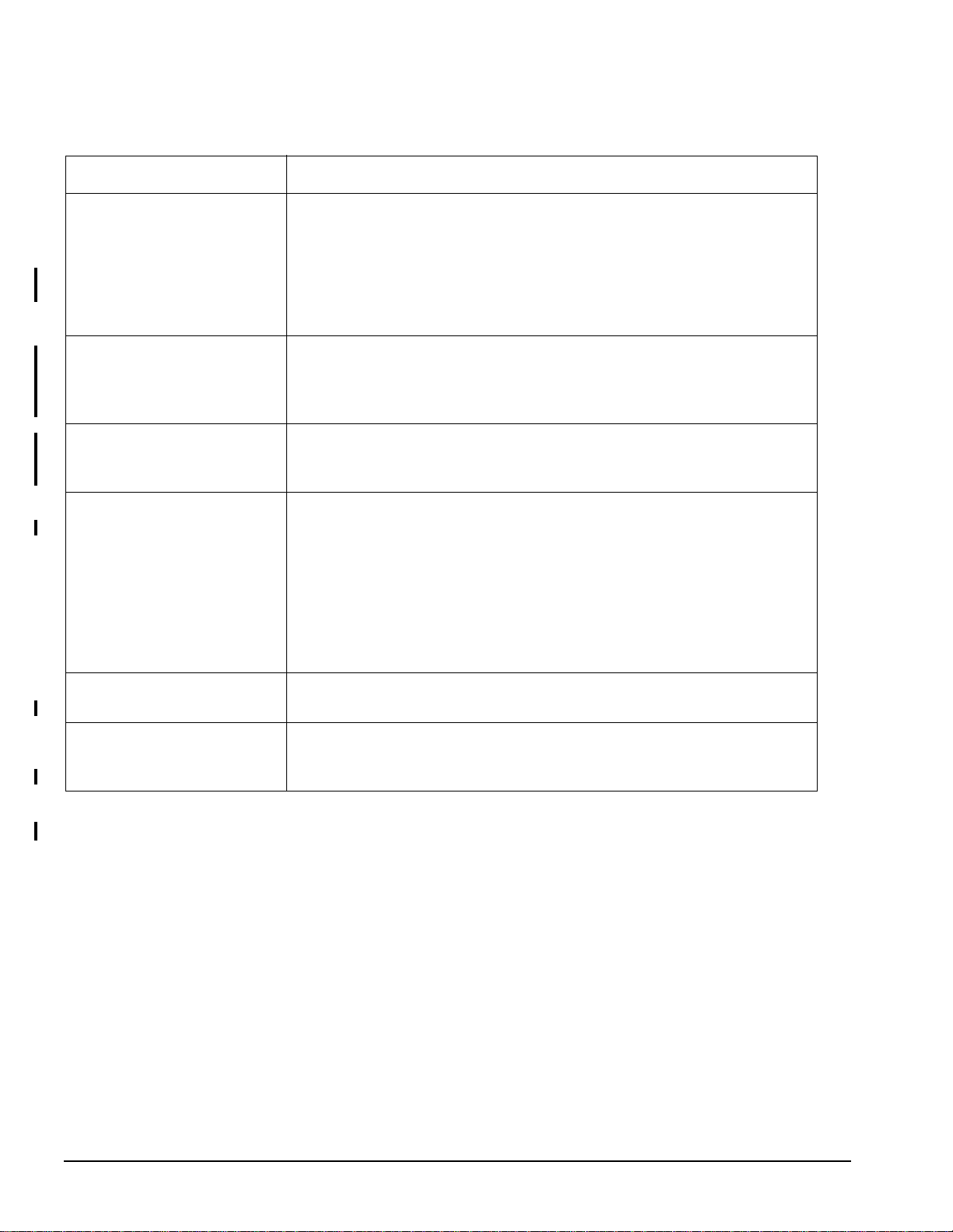
Figure 1-1 illustrates the front panel of Model 743 and Model 744 Board Computers.
Figure 1-1 Model 743 and Model 744 VME Board Computer Front View
Table 1-2 lists the feature sets of the Model 743i VME Board Computer
1-2
Page 11
Model 743 and Model 744 VME Board Computers
.
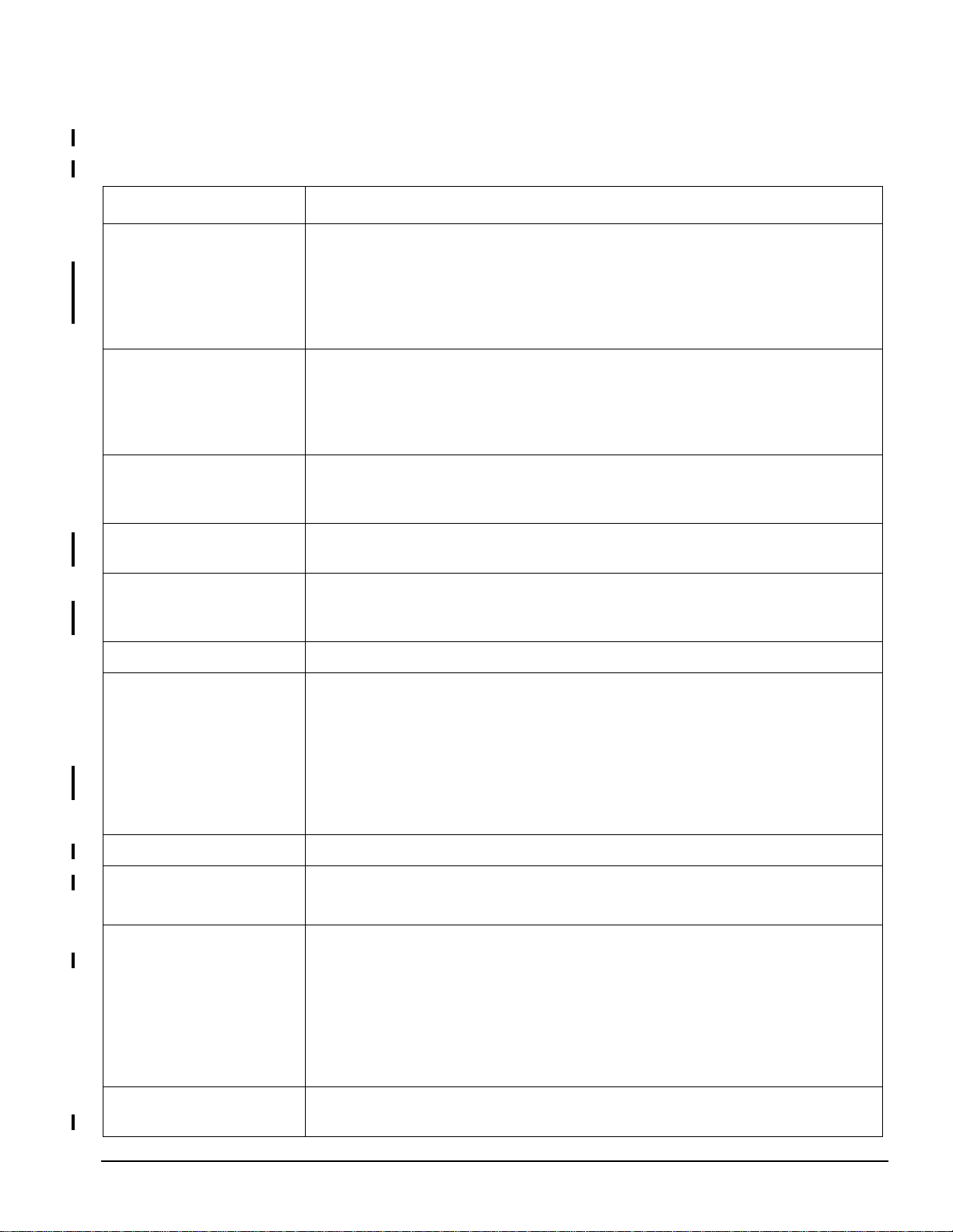
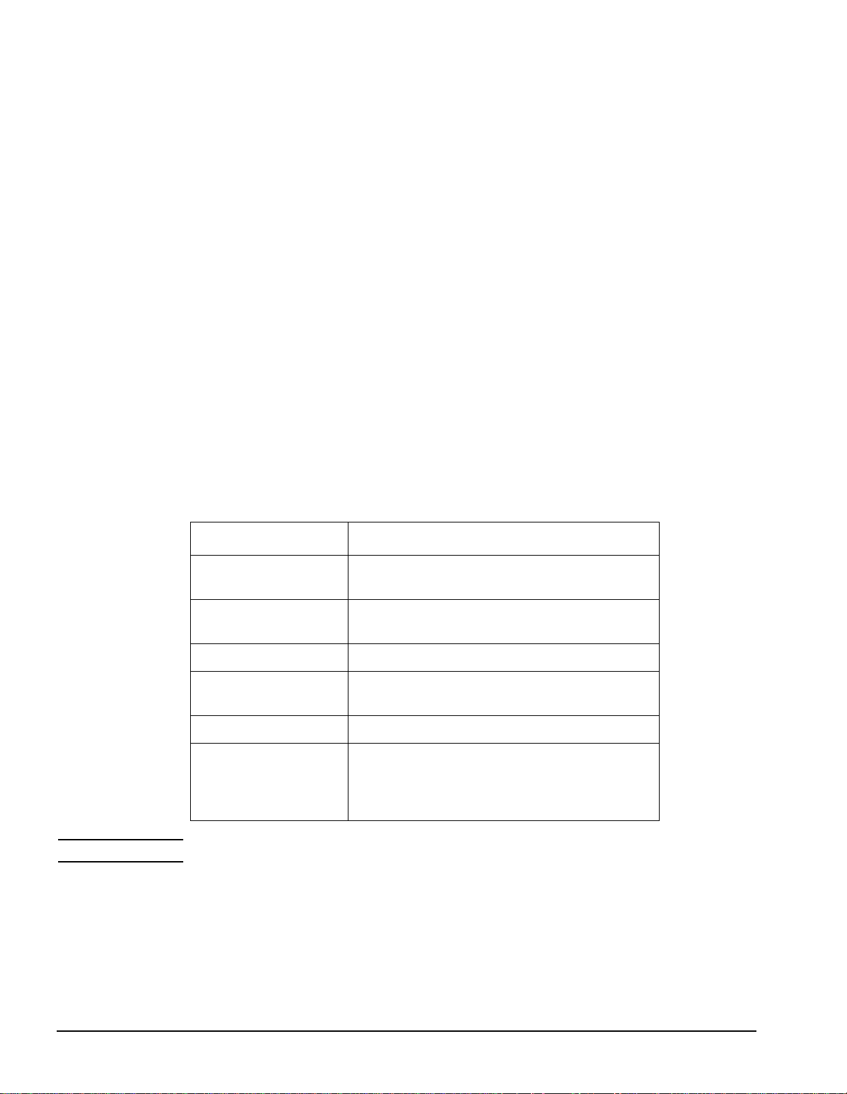
Table 1-1 Model 743i (A4260A) and 743rt (A4261A) Features
Feature Specifications
VME Slot Configuration Single Slot - Standard features
Two Slots - GSC expansion kit (A4219A),
or PMC Bridge Adapter (A4504A)
Three Slots - ATM card (J3420A) and GSC expansion kit (A4219A),
or PCI Mezzanine Card (PMC) Expansion Adapter (A4509A)
CPU 64 or 100 MHz PA-RISC PA7100-LC
256 KB cache
1 KB on-chip instruction cache
Floating point coprocessor
64-bit wide ECC memory controller
Clocks Battery backed real-time clock
Interval timers (one 32-bit and two 16-bit)
Watchdog timer
General Information
Operating System HP-UX 9.05 or later, or
HP-RT 2.21 patch or later
User Interface HP VUE graphical user interface (HP-UX 9.05 or later)
HP CDE graphical user interface (HP-UX 10.10 or later)
HP-RT
Compatibility Source and binary code compatible with the Series 700 pr oduct family
Monitors Single or multiple display depending on the number of installed graphics options (on-
board and/or external). HP-UX 9.x sup po rt s up to two di sp lay s an d HP- UX 10 .x supports
up to three displays.
Color monitors
17-inch, 1280 x 1024
19-inch, 1280 x 1024
Terminals - Text only connected to RS-232C port
Optional Graphics On-board (option 202=64MHz w/graphics or option 204=100MHz w/graphics)
Main Memory Single VME Slot Configuration - 32 to 128 MB (A4265A=32MB, or A4266A=64MB)
Two VME Slots Configuration - 32 to 256 MB
Standard Features Internal SCSI-2 single-ended bus
CD-Quality audio (not supporte d on HP-RT)
Two asynchronous RS-232-C ports
One HP parallel port
One LAN AUI port
Two mini-DIN PS/2 ports
Two sites for memory cards
Video connector for onboard graphics
Two Slot Upgrades PMC Bridge Adapter (A4504A) with two PMC sites
GSC Expansion kit (A4219A) with two GSC sites
1-3
Page 12
General Information
Model 743 and Model 744 VME Board Computers
Table 1-1 Model 743i (A4260A) and 743rt (A4261A) Features
Feature Specifications
Three Slot Upgrades PMC Expansion Adapter (A4509A) with two additional PMC sites
ATM card (J 3420A) (Requi res GSC expansio n kit A4262A - o ne additional s ite supported
for 3x5 GSC card) (Not available with HP-RT)
Table 1-2 lists the feature sets of the Model 744/132L VME Board Computer
.
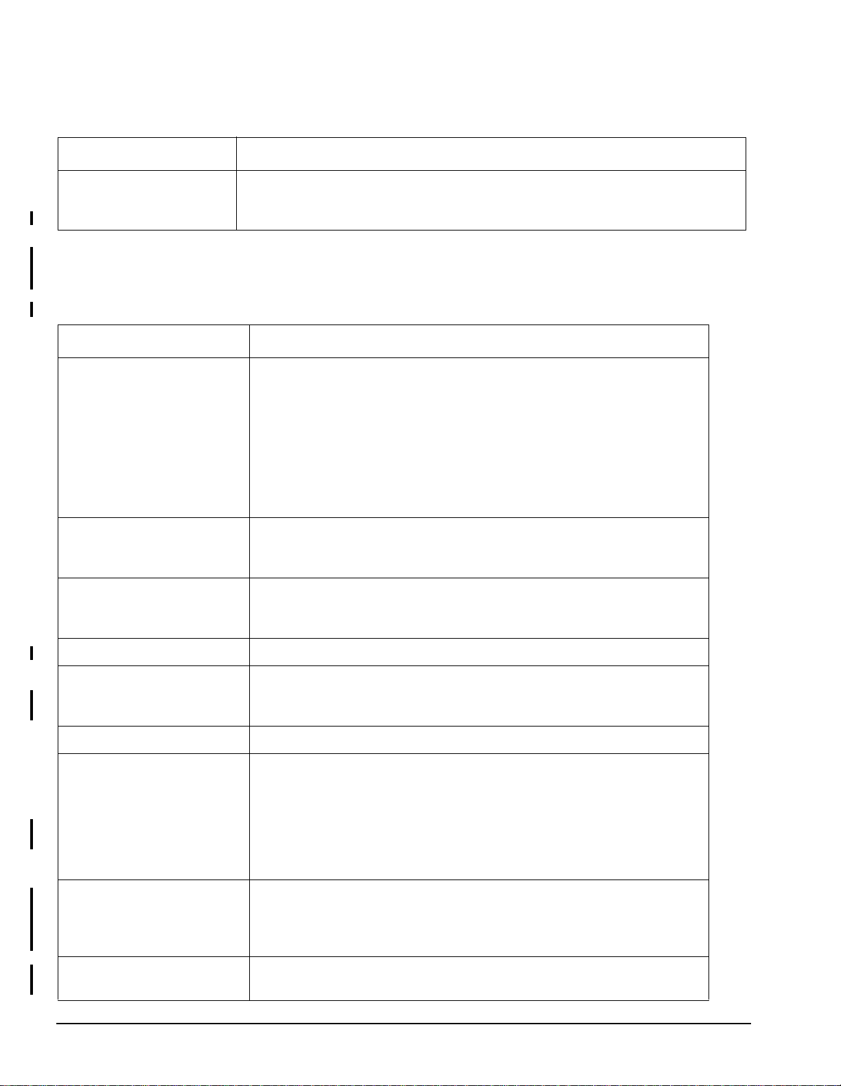
Table 1-2 Models 744/132L (A4500A) and 744rt/132L (A4520A) Features
Feature Specifications
VME Slot Configuration Single Slot - Standard features
Two Slots - PMC Bridge Adapter (A45 04A)
GSC expansion kit (A4219A)
HCRX graphics (A4315A or A4316A)
FWD SCSI (A4268A)
8-plane graphics (A4267A)
Three Slots - ATM card (J3420A) and expansion kit (A4219A), or
PMC Expansion Adapter (A4509A)
CPU 132 MHz PA-RISC PA7300-LC
128 KB Primary internal cache (64 KB instruction cache, 64KB
data cache)
Clocks Battery backed real-time clock
Interval timers (one 32-bit and two 16-bit)
Watchdog timer
Operating Sy stem HP-UX 10.20 or later, or HP-RT 2.21 patch or later
User Interface HP VUE graphical user interface (HP-UX)
HP CDE graphical user interface (HP-UX)
HP-RT
Compatibility Source and binary code compatible with the Series 700 product family
Monitors Single or multiple display depending on the number of installed graphics options
(on-board and/or external)
Color monitors
17-inch, 12 80 x 1024
19-inch, 12 80 x 1024
Terminals - Text only connected to RS-232C port
Optional Graphics Onboard (A4500A option 120)
PMC Visualize-EG Graphics Card (A4979A)
Note: A maximum of four graphics displays are allowed with HP-UX 10.10
ACE and later releases, a maximum of one graphics display with HP-RT.
Main Memory Single VME Slot Configuration - 64 to 256 MB A4503A, A4449A, A6005A)
Two VME Slots Configuration - 64 to 1024 MB
1-4
Page 13
Model 743 and Model 744 VME Board Computers
Table 1-2 Models 744/132L (A4500A) and 744rt/132L (A4520A) Features
Feature Specifications
Standard Features Internal SCSI-2 single-ended bus
CD-Quality audio (not supported on HP-RT)
Two asynchronous RS-232-C ports
One HP parallel port
One LAN AUI port
Two mini-DIN PS/2 ports
One site for memory card stack
Video connector for onboard graphics
Conversion cables are included in base kit.
Two Slot Upgrades PMC Bridge Adapter (A4504A) with two PMC sites
GSC Expansion kit (A4219A) with two GSC sites)
Three Slot Upgrades PMC Expansion Adapter (A4509A)
ATM card (J3420A) (Requires GSC expansion kit A4219A - one additional site
supported for 3x5 GSC card) (Not available with HP-RT.)
General Information
Table 1-3 lists the feature sets of the Model 744/165L VME Board Computer
.
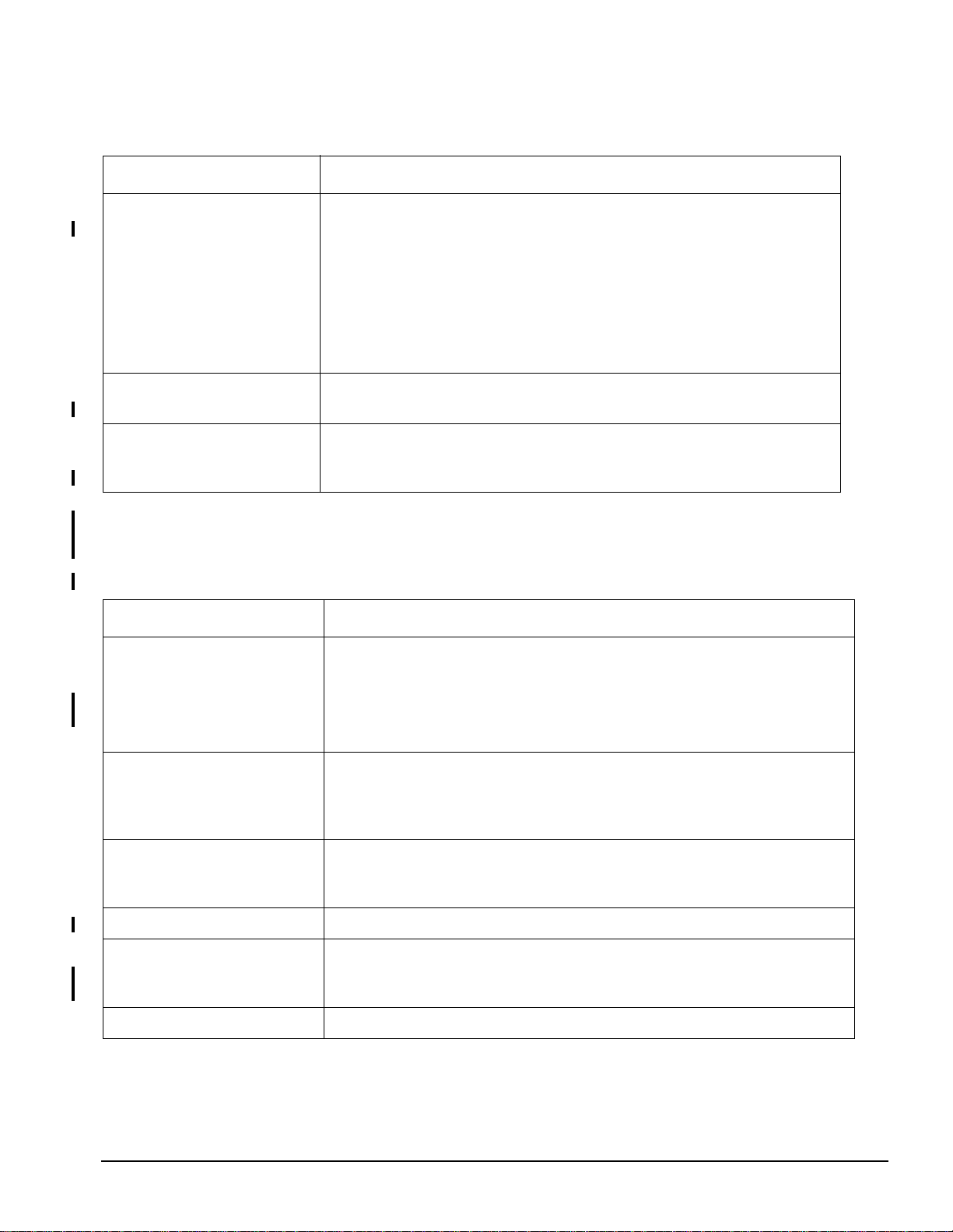
Table 1-3 Model 744/165L (A4511A) and 744rt/165L (A4512A) Features
Feature Specifications
VME Slot Configuration Single Slot - Standard features
Two Slots - PMC Bridge Adapter (A4504A)
GSC expansion kit (A4219A)
Three Slots -ATM card (J3420A) and expansion kit (A4219A), or
PMC Expansion Adapter (A4509A)
CPU 165 MHz PA-RISC PA7300-LC
128 KB Primary internal cache (64 KB instruction cach e, 64KB data
cache)
512 KB Secondary external cache
Clocks Battery backed real-time clock
Interval timers (one 32-bit and two 16-bit)
Watchdog timer
Operating System HP-UX 10.20 or later, or HP-RT 3.01 patch or later
User Interface HP VUE graphical user interface (HP-UX)
HP CDE graphical user interface (HP-UX)
HP-RT
Compatibility Source and binary code compatible with the Series 700 product family
1-5
Page 14
General Information
Model 743 and Model 744 VME Board Computers
Table 1-3 Model 744/165L (A4511A) and 744rt/165L (A4512A) Features
Feature Specifications
Monitors Single or multiple display depending on the number of installed graphics options
(on-board and/or external)
Color monitors
17-inch, 1280 x 1024
19-inch, 1280 x 1024
Terminals - Text only connected to RS-232C port
Optional Graphics Onboard (A4500A option 120)
PMC Visualize-EG Graphics Card (A4979A)
Note: A maximum of four graphics displays are allowed with HP-UX 10.10 ACE
and later releases, a maximum of one graphics display with HP-RT.
Main Memory Single VME Slot Configuration - 64, 128, or 256 MB (A4503A, A4449A or
A6005A)
Two VME Slots Configuration - 64 MB to 1024 MB
Standard Features Internal SCSI-2 single-ended bus
CD-Quality audio (not supporte d on HP-RT)
Two asynchronous RS-232-C ports
One HP parallel port
One LAN AUI port
Two mini-DIN PS/2 ports
One site for memory card stack
Video connector for onboard graphics
Conversion cables are included in base kit.
Two Slot Upgrades PMC Bridge Adapter (A4504A) with two PMC sites
GSC Expansion kit (A4219A) with two GSC sites
Three Slot Upgrades PMC Expansion Adapter (A4509A)
ATM card (J3420A) (Requires GSC expansion kit A4219A - one additional site
supported for 3x5 GSC card) (Not available with HP-RT.)
1-6
Page 15

General Information
Model 743 and Model 744 VME Board Computers
Supported Configurations
This section discusses the following supported configurations: memory, system graphics,
external devices, cables, and keyboard and mouse.
Hewlett-Packard only supports products having Hewlett-Packard approved parts, accessories, peripherals, operating systems, and application programs.
Model 743 Memory
Standard memory is Error Checking and Correcting (ECC) RAM cards. Up to four RAM
cards may be installed. RAM upgrades include:
• HP A4265A 32 MB RAM Card
• HP A4266A 64 MB RAM Card
Model 743 VME Board Computers use custo m 60-ns TSOP-based RAM card s. Use of TSOP
packaging allows adequate cooling in single-slot installations.
T wo stack location s for RAM cards a re used. The primary RAM stack is on t he right s ide, the
secondary one is on the left side. Only one RAM card can be used in the secondary, or left
stack, if a GSC+ card is ad ded i n t he s eco ndar y GSC+ s lot . Thr ee RAM ca rds can be used in
the primary stack. If more tha n one RAM card is use d in eith er stac k, the opti onal HP 4262 A
GSC Expansion Kit or A4504A PMC Bridge Adapter (HP-UX only) must be installed; then
the board computer will occupy two VME slots in a VME chassis.
RAM cards may be placed in any order. A higher density card can be added on top of a low
density card and vice versa.
Model 744 Memory
Standard memory is Error Checking and Correcting (ECC) RAM cards. Up to four RAM
cards may be installed. RAM upgrades include:
• HP A4501A 64 MB RAM Card
• HP A4449A 128 MB RAM Card
• HP A6005A 256 MB RAM Card
Model 744 VME Board Computers use custo m TSOP-based RAM cards. Us e of TSOP pack aging allows adequate cooling in single-slot installations.
There is only one stack l ocation f or RAM cards on the Model 744. Memory ca rds are st acked
in the same orientat ion; th at is, t here is no nee d to rot ate cards 18 0 degree s rela tive t o the previously inserted card as in the Model 743. If more than one RAM card is used, the optional
HP 4219A GSC expansion kit must be installed; then the board computer will occupy two
VME slots in a VME chassis.
When mixing the 128 MB and 256 MB RAM card wi th c ar ds o f a different capacit y, the 128
MB and 256 MB card(s) must always be in the lower memory slots.
1-7
Page 16
General Information
Model 743 and Model 744 VME Board Computers
System Graphics
The Model 743 and Model 744 Board Computers can be ordered with optional on-board
graphics.
The Model 744 supports up to four optional PMC Visualize-EG graphics cards.
The HP-UX 10.20 ACE operating system supports up to four displays.
The HP-RT operating system supports only one graphics display.
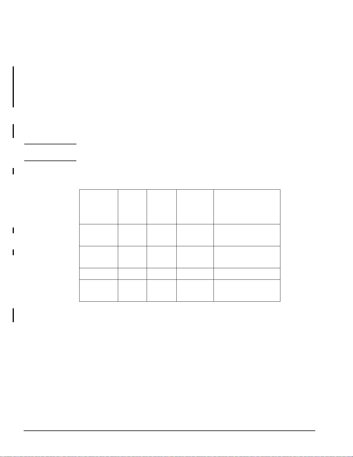
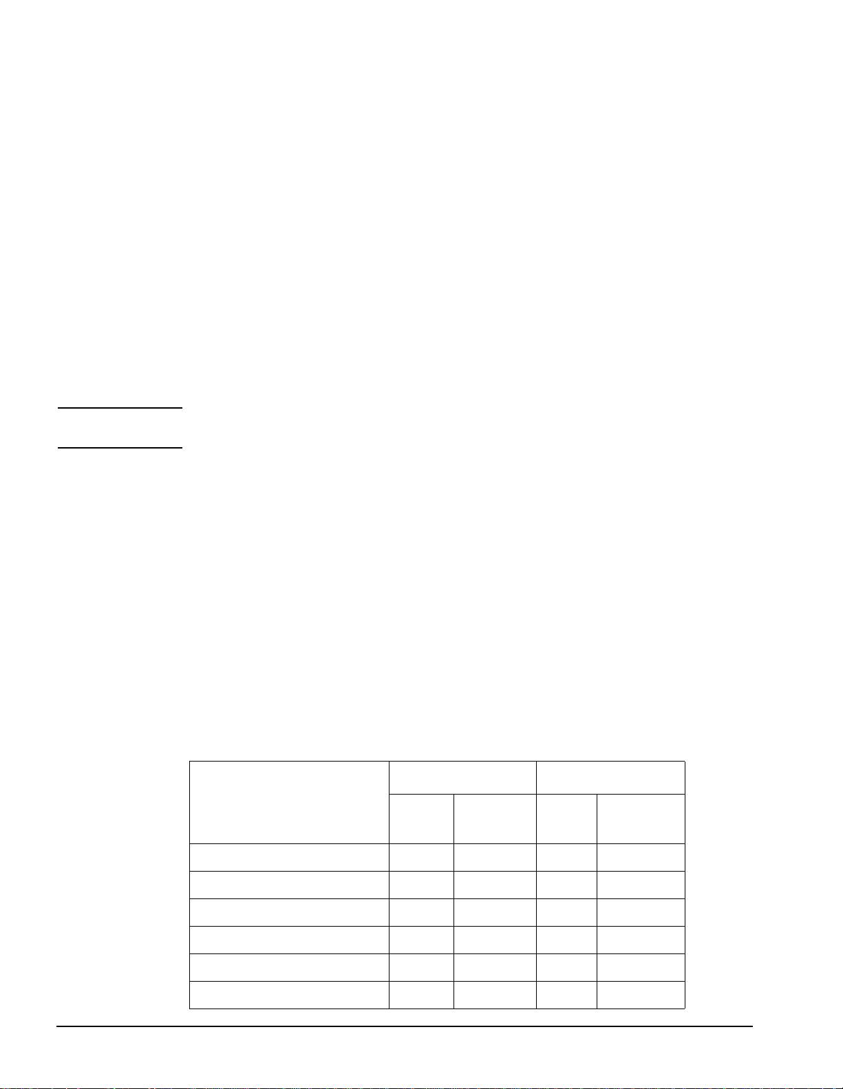
Table 1-4 shows the display resolutions and refresh rates that are supported on current and
older graphics devices.
NOTE: The HCRX graphics options support a Frame Buffer of 1280 by 1024; therefore, the monitor
selected must support a resolution of 1280 by 1024.
Table 1-4 Supported Graphics Configurations
Display
Pixel
Resolution
1280x1024* 75 Hz
1024 x 768* 75 Hz
800 x 600 75 Hz • •
640 X 480 75 Hz
Display
Refresh
Rate
72 Hz
70 Hz
60 Hz
On-
board
Graphic
s
•* •* •
•* •*
••
HP A4267A
GSC Card
8-Plane
HP A4315A 8-Plane
or
HP A4316A 24-Plane
HCRX Graphics
•
With the D8900A monitor, HP-UX 10.20 ACE or 11.00, and the A4267A graphics card or
Model 743 onboard graphics, these resolutions are not supported.
1-8
Page 17
General Information
Model 743 and Model 744 VME Board Computers
Model 743 and Model 744 External Devices
The Model 743 and Model 744 support the following external devices:
• LAN Transceiver (Medium Attachment Unit)
HP 28641B ThinLAN Ethernet Transceiver (order number A2670A)
HP 28685B Ethertwist Transceiver (order number A2671A)
HP 28683A Fiber Optic Hub/Transceiver
• Speaker: 8 ohm impedance with 1/8-inch sub-miniature stereo connector
• Single-ended SCSI through the onboard SE SCSI adapter
Keyboard and Mouse
The Model 743 and Model 744 support the mouse with mini-DIN connector (PS/2) and keyboard with mini-DIN connector (PS/2) included in the HP A4030D Localization Kit.
Model 743 and Model 744 Cables
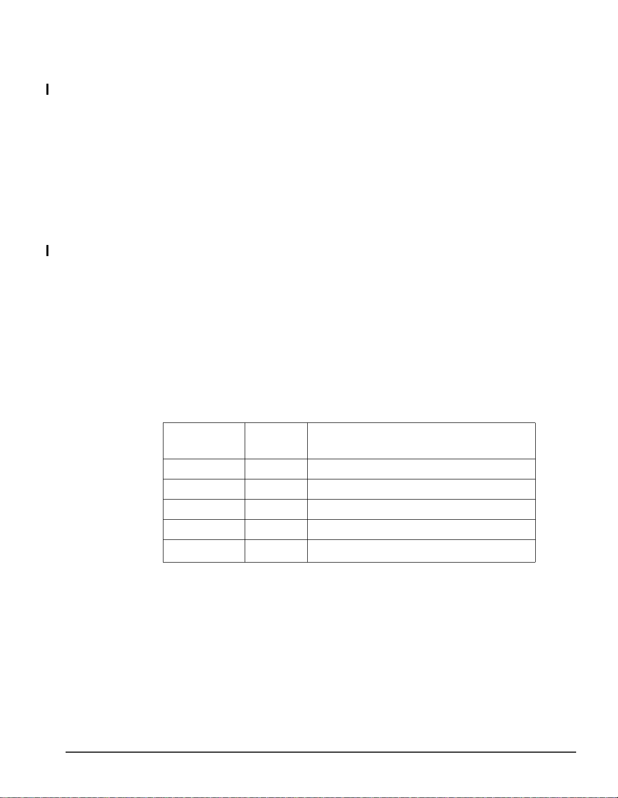
Table 1-5 and Table 1-6 show the part numbers for standard cables and conversion cables
used to interface with the Model 743 and Model 744 I/O backplanes.
Drawings showing mechanical and electrical characteristics for these cables are available.
Refer to chapter 4 in this manual for more information.
Table 1-5 Model 743 and Model 744 Standard Cables
Product
Number
HP 24524G RS-232 3-meter terminal cable; 9-pin female to 25-pin male
HP 24524H RS-232 3-meter modem cable; 9-pin female to 25-pin female
HP C2950A HP Parallel DB 25-pin male to 36-pin Centronics male
HP 92284A HP Parallel DB 25-pin male to 25-pin male
HP K2296 SCSI-2
a.Additional lengths are available.
Interface Cable Type
0.9 meter high-density 50-pin to standard bail lock
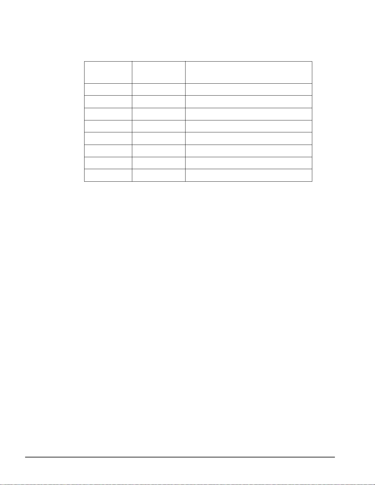
Conversion cables provide a way to connect a standard cable to the high-density connectors
on the Model 743 and Model 744 front panels.
All conversion cables, except the A4167A, are 762 plus/minus 30mm (30 plus/minus 1.18
inch) long. The A4167A cable is 250 mm (10 inches) long.
a
1-9
Page 18
General Information
Model 743 and Model 744 VME Board Computers
Table 1-6 Model 743 and Model 744 Conversion Cables
Product
Number
HP A4300A HP parallel High-density 25-pin to standard 25-pin female
HP A4301A RS-232 High-density 9-pin to standard 9-pin male
HP A4302A Audio High-density 9-pin to stereo line-in
HP A4303A LAN High-density 15-pin to 15-pin AUI
HP A4304A Video (743) High-density 15-pin to standard 15-pin female
HP A4223A Video (744) High-density 15-pin to standard 15-pin female
HP A4305A Video (743/744) High-density 15-pin to EVC c onnector
HP A4167A Video (GSC card) Standard 15-pin to EVC connector
Interface Cable Type
1-10
Page 19

General Information
Model 743 and Model 744 VME Board Computers
Model 743 and Model 744 Functional Description
This section describes the major components of the Model 743 and Model 744 VME board
computers
The system board contains the following functionality:
• Boot ROMs
•CPU
• Graphics
• I/O controller, which controls these interface circuits:
•Audio
• HP Parallel
• LAN
• RS-232-C
• SE SCSI
• Keyboard and mouse
• Battery-backed Real Time/Time-of-Day clock
• Memory controller
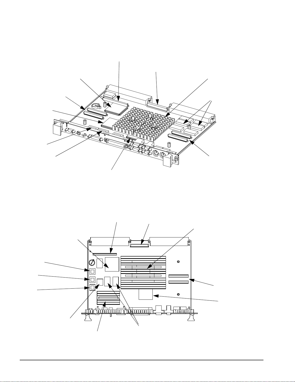
Figure 1-2 shows the major components of the Model 743.
Figure 1-3 shows the major components of the Model 744.
1-11
Page 20
General Information
Model 743 and Model 744 VME Board Computers
VME Controller
PCMCIA Connector
GSC Bus Connector
CPU (under heatsink)
RAM Card Connectors
I/O Controller
Boot ROM
EEPROM
Optional Onboard
Graphics Controller
Figure 1-2 Model 743 VME Board Computer Functional Components
PCMCIA Connector
GSC Bus Connector
CPU (under heatsink)
Video RAM
(optional onboard graphics)
RAM Card Connectors
VME Controller
EEPROM
IODC
PDC
Audio CODEC
Video RAM
Optional Onboard
Graphics Controller
(optional onboard graphics)
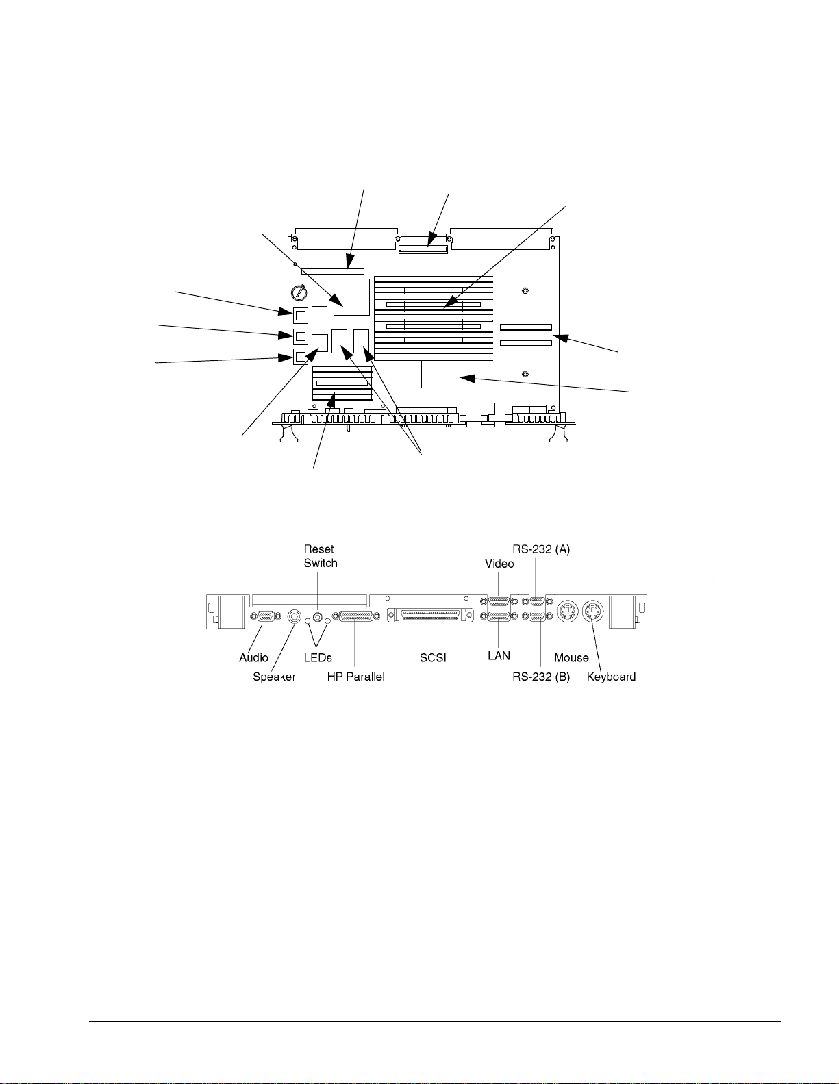
Figure 1-3 Model 744 VME Board Computer Functional Components
1-12
RAM Card Connectors
I/O Controller
Page 21
General Information
Model 743 and Model 744 VME Board Computers
Figure 1-4 illustrates the functional architecture of the Model 743 system board.
Figure 1-4 Model 743 Functional Block Diagram
1-13
Page 22
General Information
Model 743 and Model 744 VME Board Computers
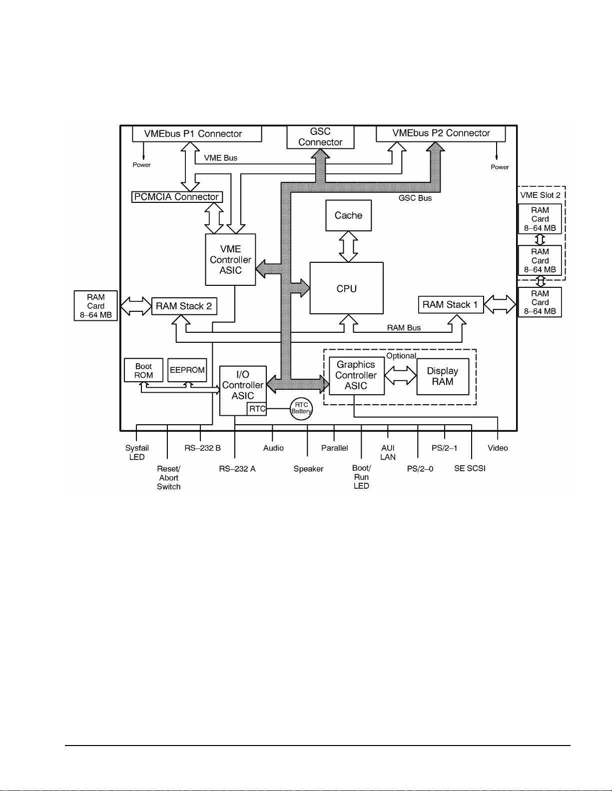
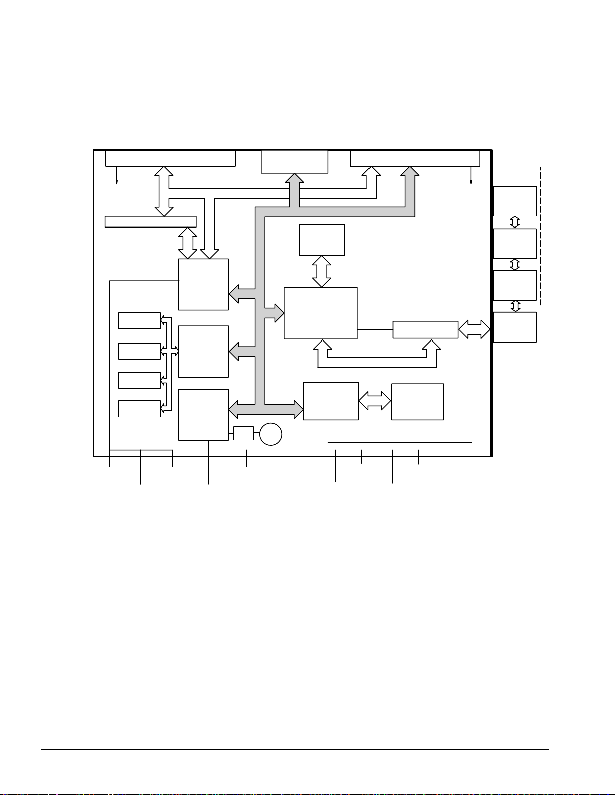
Model 744 Block Diagram
Figure 1-5 illustrates the functional architecture of the Model 744 system board.
Backplane P1 Connector
Power
Backplane Bus
Reserved Connector
Backplane
Controller
ASIC
EEPROM
REGs
PDC & IODC
SRAM
Firmware
Controller
Controller
ASIC
I/O
RTC
GSC
Connector
RTC
Battery
Second Level
Cache
(165 MHz only)
CPU
Graphics
Controller
ASIC
Backplane P2 Connector
GSC Bus
RAM Stack
RAM Bus
Display
RAM
Power
Slot 2
RAM
Card
64–256 MB
RAM
Card
64–256 MB
RAM
Card
64–256 MB
RAM
Card
64–256 MB
Sysfail
LED
Reset/
Abort
Switch
RS–232 A
Audio
Parallel
Boot/
Run
LED
Figure 1-5 Model 744 Functional Block Diagram
1-14
Speaker
AUI
LAN
PS/2–0
PS/2–1
VideoRS–232 B
SE SCSI
Page 23
CPU Circuit
The Model 743 uses a Hewlett-Packard PA-RISC 7100-LC CPU chip and the Model 744
uses a Hewlett-Packard PA-RISC PA7300-LC CPU chip. The CPU chip is the heart of the
CPU circuit. It executes instructions and controls the other circuits.
Table 1-7 lists the CPU performance figures of the Model 743 with HP-UX and Table 1-7
lists the CPU performance fig ures for the Mod el 744 with HP-UX.
Table 1-7 Model 743 CPU Performance
Model 743i/64 743i/100
HP-UX Version 9.05 10.x 9.05 10.x
MFLOPS (DP) 25.3 22.2 37.8 34.3
MIPS 77.7 121.6 121.8
SPECfp92 96.5 97.05 137.0 138.3
General Information
Model 743 and Model 744 VME Board Computers
SPECint92 66.6 81.1 100.1 115.0
SPECfp95 2.6 3.47
SPECint95 1.9 2.89
Table 1-8 Model 744 CPU Performance
Model 744 Performance
Based on HP-UX 10.20
SPECint95 5.90 7.90
SPECfp95 6.22 7.64
132 MHz 165 MHz
1-15
Page 24
General Information
Model 743 and Model 744 VME Board Computers
Boot ROM Circuit
The Boot ROM circuits have Boot ROMs containing 2x526 Kilobytes (Model 744) or 512
Kilobytes (Model 743) of information that does the following:
• Manages the internal interface configurations
• Searches for and boots an operating system
• Self-tests the board computer's main circuits
• Starts the CPU functions
An EEPROM stores the following information:
• Internal interface configurations
• LAN ID number
• System board serial number
NOTE: The workstation's LAN ID number's last 6 characters are labeled on the EEPROM. The first
group of six digits are typically “080009” or “0060b0” (the HP-owned prefix).
A PLL Clock Module generates the system clock, on which all timing is based.
Graphics Circuit
System boards with on-boa rd graphic s or graphi cs cards hav e a graphics cont roller ASI C and
the display RAM. Resolution and refresh rate can be configured using the boot console handler for several types of monitors.
A keyboard must be connected to the PS/2 0 port if graphics are used as part of the console
path. When a graphics device is specified as the console path, the boot ROM first checks for
a keyboard by using the keyboard search list. If a keyboard is not found in this search list,
graphics are not enabled.
Table 1-9 summarizes the graphics performance figures for the Model 743 with HP-UX and
Table 1-9 summarizes the graphics performance figures for the Model 744 with HP-UX.
Table 1-9 Model 743 Graphics Performance
2D/3D vectors/sec 1.4M 1.5M 1.6M 2.3M
Model 743 i/64 Model 743 i/100
8 Plane
HCRX 8
and 24
8 Plane
HCRX 8
and 24
1-16
Lighted, shaded quadrilateral/sec 15K 14K 23K 23K
PLBsurf 19 21 23 32
Triangles/sec 26K 25K 40K 40K
X11 Vec/sec 1.2M 1.5M 1.2M 2.1M
Xmark93 8.1 9.3 8.6 12.1
Page 25
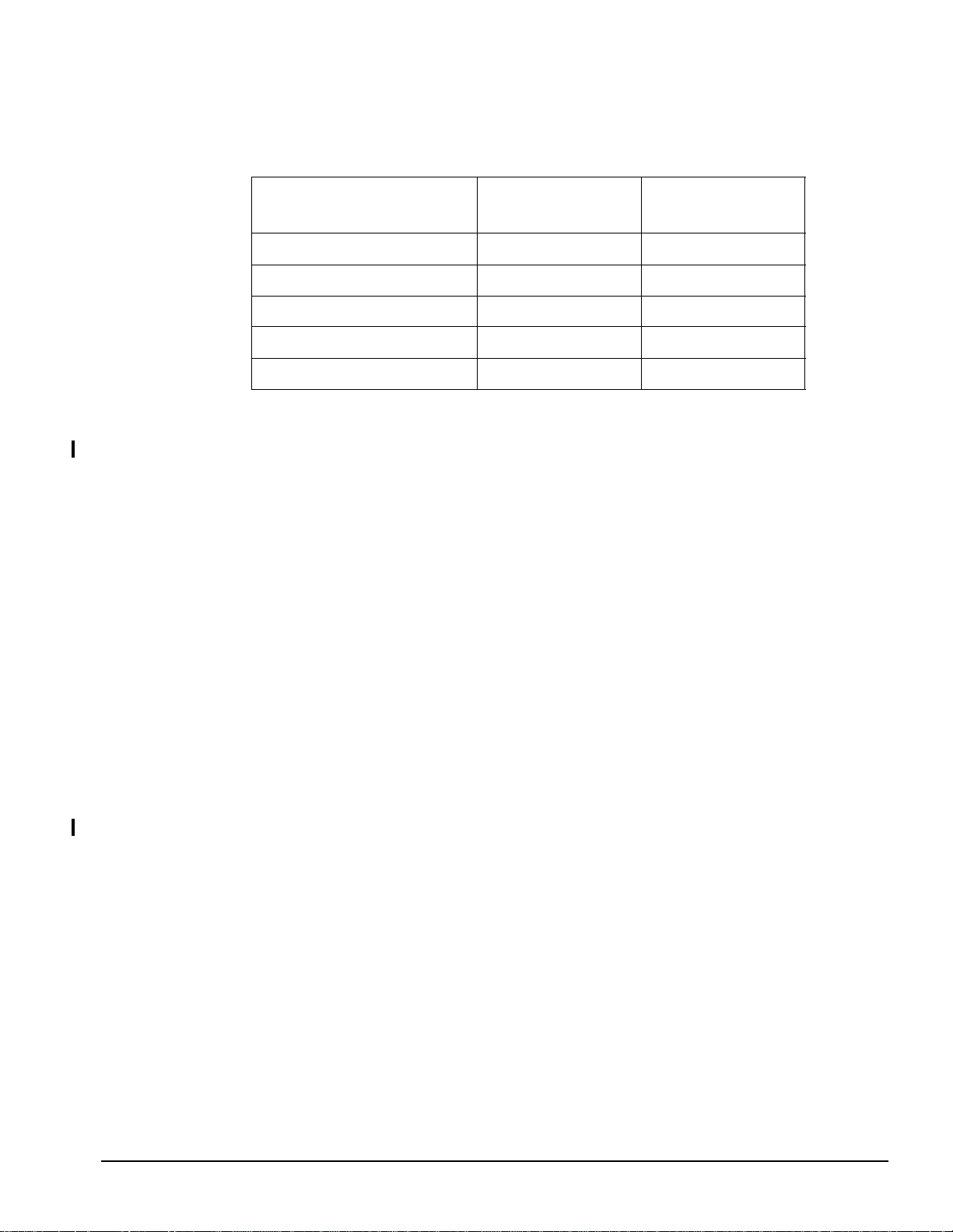
Table 1-10 Model 744 Graphics Performance
General Information
Model 743 and Model 744 VME Board Computers
On-board
HP Visualize-EG Graphics
X11 Lines 5.74M TBD
Xmark93 33.11 36.47
PLBsurf93 49.7 TBD
PLB wire93 116.1K 135.4K
2D/3D vectors/sec 3.1M TBD
132 MHz 165 MHz
Model 743 Memory Controller Circuit
The CPU’s memory controller circuit manages memory. Up to 256 MB of RAM may be
installed. An Error Checking and Correcting (ECC) function checks memory word read/write
operations. The ECC function detects single-bit and double-bit errors. Single-bit errors are
corrected. Double-bit errors are detected but not corrected. The memory controller circuit
uses a 64-bit memory bus. The following two RAM card locations are used:
• RAM stack 1, behind the PS/2 connectors on the system board. Up to three RAM cards ar e
supported.
Physical RAM slot positions are:
Bottom RAM card, slot 0
Middle RAM card, slot 1
Top RAM card, slot 2
• RAM stack 2, behind the audio connectors on the system board. One RAM card is supported and is in physical RAM slot 3.
Model 744 Memory Controller Circuit
The CPU’s memory controller circuit manages memory. Up to 1 GB of RAM may be
installed. An Error Checking and Correcting (ECC) function checks memory word read/write
operations. The ECC function detects single-bit and double-bit errors. Single-bit errors are
corrected. Double-bit errors are detected but not corrected. The memory controller circuit
uses a 132-bit memory bus. One RAM card location is used, behind the PS/2 connectors on
the system board. Up to four RAM cards are supported.
Physical RAM slot positions are:
Bottom RAM card, slot 0
Second RAM card, slot 1
Third RAM card, slot 2
Fourth RAM card, slot 3
1-17
Page 26
General Information
Model 743 and Model 744 VME Board Computers
RAM Cards When mixing RAM cards of different capacities that include 128 MB and 256
MB cards, the 128 MB and 256 MB cards must be installed into the lowest numbered memory sites. Memory mapping at turn on determines the size of the card in each location.
LED Displays
Model 743 and 744 VME Board Computers have two LEDs that indicate various system
functions: a system failure LED and a functional LED. See Table 1-11.
Table 1-11 LED Meanings
SYSF AIL
(Red)
Off Off No Power Check for board seating in
On 2Hz Flash Normal Power-on/self-
On Off Memory Failure Troubleshoot for failed RAM
On 1 Flash/sec. CPU (board) Failure Replace the system board.
On 4 Flash/sec. No console identified Check the console search
On On OS is booted with
Off On OS is booted with
POWER
(Green)
Meaning Possible So lution
chassis.
test
card or problem with the
RAM connection.
path and keyboard connections. If no problem is found,
replace the system board.
Check the Operating System
VME services failure
VME services OK
VME services. Check that
VME services is configured
in the kernel.
1-18
I/O Contro ller ASIC
I/O control by the system board’s I/O controller ASIC includes the following interfaces:
•Audio
• AUI LAN
• HP Parallel
• PS/2 Ports 0 and 1
• RS-232 Port A
• Single-Ended SCSI
• Speaker
The batter y-backed real-time clock is also implemented in the I/O controller ASIC.
The connectors for the system board's built-in interfaces are on the front panel. Most use
micro-miniature connectors that require special conversion cables in order to use standard
interface cables.
Page 27
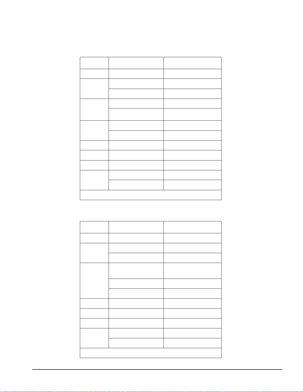
Table 1-12 summarizes I/O performance figures for the Model 743.
Table 1-12 Model 743 I/O Performance
I/O Type Performance Notes
Audio * 48 KHz Sampling rate
FW SCSI * 10 MB/second Asynchronous
20 MB/second Synchronous
GSC 32 MHz 64 MHz clock frequency
General Information
Model 743 and Model 744 VME Board Computers
1
33
/3 MHz
HP Parallel 300+ KB/second With DMA
200 KB/second Sustained
LAN 10 Mb/second
PS/2 2.5 K 11-bit samples/sec
RS-232 460.8 Kbps
SE SCSI 5 MB/second Synchronous
1.5 MB/second Asynchronous
* Not supported in HP-RT
Table 1-13 summarizes I/O performance figures for the Model 744
Table 1-13 Model 744 I/O Performance
I/O Type Performance Notes
Audio * 48 KHz Sampling rate
FW SCSI * 10 MB/second Asynchronous
100 MHz clock frequency
20 MB/second Synchronous
GSC 33 MHz 132 or 165 MHz clock
frequency
HP Parallel 300+ KB/second With DMA
200 KB/second Sustained
LAN 10 Mb/second
PS/2 2.5 K 11-bit samples/sec
RS-232 460.8 Kbps
SE SCSI 5 MB/second Synchronous
1.5 MB/second Asynchronous
* Not supported in HP-RT
1-19
Page 28
General Information
Model 743 and Model 744 VME Board Computers
The sections that follow explain the functions of the interfaces.
Audio Model 743 and Model 744 Board Computers provide compact disc-quality audio
input and output, in stereo, with a 16-bit coder-decoder (CODEC) over a frequency range of
25-20,000 Hz. A stereo headphone mini-plug (8 ohms impedance) provides output. The stereo line-in and mono microphone mini-plugs provide input with the HP A4302A Audio
Cable.
The CODEC combines CD quality stereo A/D converters for microphone and line input levels. D/A converters for dri ving headset and line out puts are used. The input samp ling rate and
format are programmable, as are the input gain control (used for software control of recording levels) and output attenuation.
1
A
/8-inch mini-jack is used for the speaker out connection. The other audio signals are on a
9-pin micro D-sub connector. The output is capable of driving a minimum of 8 ohms. It can
also be used for higher impedance devices with little or no additional distortion.
A voice-quality audio output may be used.
For information o n p rogram ming for audio, re fer to Usin g the Audio De velope r’s Kit (B2355-
90069) and the man page audio.
Table 1-14 lists the Model 743 and Model 744 audio specifications.
Table 1-14 Model 743 and Model 744 Audio Specifications
Function Range
Headphone maximum
output level
Input sensitivity Line in, 2.0 V pp at 47 K ohms microphone, 22 mV
Programmable input gain 0 to 22.5 dB in 1.5 dB steps
Programmable output
attenuation
Programmable rates 8, 11.025, 16, 22.05, 32, 44.1, 48 KHz
Signal to noise ratio Headphone, 61 dB
2.75 V pp at 50 ohms
at 1 K ohm
0 to 96 dB in 1.5 dB steps
Line in, 61 dB
Microphone, 57 dB
NOTE: Audio CD ROMs cannot output to the audio out connector.
1-20
Page 29
AUI LAN LAN circuits use the Ethernet/IEEE 802.3 standard interface. Only the Attach-
ment Unit Interface (AUI) versi on is used ; no BNC connec tor is provi ded for ThinLAN. The
AUI connector enables connec tions to an exte rnal MAU using the HP A4303A adapt er cable.
Table 1-15 summarizes the LAN AUI interface specifications.
Table 1-15 LAN AUI Specifications
Connector type 15-pin MDSM
Controller Intel 82596CA compatible megacell
Data rate 10 Mbits/sec
Electrical interface AUI
T yp e IEEE 802.3, Ethernet 1.0
Single-Ended SCSI The 8-bit single-ended implementation is compatible with the current
Series 700 products and supports 5 MB/sec data transfer rates.
The SCSI bus is terminated to 3.3 volts through 127 ohms on the system board. If the board
computer is used in a VME chassis having internal mass storage devices, all devices except
the last one must have their terminator removed. If an external disk drive is used, an active
terminator must be used on the last drive’s uncabled connector.
Table 1-16 summarizes the specifications for the single-ended SCSI interface.
General Information
Model 743 and Model 744 VME Board Computers
Table 1-16 Single-Ended SCSI Interface Specifications
Controller NCR 53C710 compatible macrocell, Rev D
Connector type SCSI-II, ALT-1 50-pin high-density thumbscrew
Data rate Asynchronous, 1.5 MBs/second
Synchronous, 5 MB/second
Device limits
Maximum external
cable len gth
Type SCSI-II (ANSI X3.131-1986), 8-bit, single-ended
a.The board computer is the host controller.
7 internal and/or external devices plus the host controller
4 meters (13.1 feet)
a
1-21
Page 30
General Information
Model 743 and Model 744 VME Board Computers
HP Parallel The parallel port is compatible with Centronics standards, plus some additional
features found in HP Series 700 workstations. It supports a bi-directional register model
interface. An 8-bit parallel, synchronous interface is used.
A high-density micro D-sub connector is used for the HP Parallel interface. An HP A4300A
adaptor cable is required to convert to standard PC compatible 25-pin female D-sub.
Table 1-17 summarizes the specifications for the HP parallel interface.
Table 1-17 HP Parallel Interface Specifications
Connector type Female 25-pin micro D-sub
Data rate >300 Kilobytes/second with DMA
200 Kilobytes/second sustained
Device limit 1
Type Centronics® and BUSY handshakes
PS/2 Ports 1 and 0 There are two PS/2 style serial ports: one PS/2 keyboard port and one
PS/2 mouse port.
RS-232 There are two serial interfaces. The I/O controller ASIC controls port A, and the
VME controller ASIC controls port B. Each supports CTS/RTS hardware handshaking. An
HP A4301A adaptor cable is required to convert it to a standard PC compatible, 9-pin male
D-sub. The maximum baud rate listed in Table 1-18 is the hardware limit. Actual transfer
rates depend upon the operating system and application load.
Table 1-18 summarizes the specifications for RS-232-C.
NOTE: The RS-232 port B is not active until VME Services is up and running.
Table 1-18 RS-232-C Interface Specifications
Baud rate 50 to 460.8 Kb/second
Connector type 9-pin female micro D-sub
Controller 16550 UART compatible megacell
Parity Odd, even, none, one, zero
Stop bits 1, 1.5, 2
Type EIA RS-232-C, CCITT V.24/V.28
Word size 5 to 8 bits
Battery-Backed Real-Time Clock The battery-backed clock is implemented in the I/O con-
troller ASIC. Once power is applied to the system board, the battery-backed clock time is
read by the operating system only during system initialization. Once the operating system is
booted, real time is kept by us ing the timer bui lt into the CPU. The battery-ba cked real-time
clock is updated by the operating system only when the user (“root” or “super-user”) explicitly requests it though the date command. The clock has a resolution of 1 second. The accuracy of the clock is wit hin ±5 seco nds every 24 hour s when the oper ating temper ature is from
0 to 55 Deg.C.
1-22
Page 31

VME Controller ASIC
A VME controller ASIC, with the VME backplane it plugs into, manages the board computer’s interface to the VMEbus. The VME controller ASIC also controls the RS-232 B port
interface.
Table 1-19 shows the VME addressing capabilities and Table 1-20 shows data transfer capabilities of the VME controller ASIC.
Table 1-19 VME Addressing Capabilities
Function Capabilities
DMA as master A16, A24, A32 with programmable address modifiers
Location monitor A16, A24, A32
Message FIFO as slave A16, A24, A32
PA memory as slave A24, A32
Processor as master A16, A24, A32 with programmable address modifiers
General Information
Model 743 and Model 744 VME Board Computers
Table 1-20 VME Data Transfer Capabilities
Function Capabilities Supported Transfer Type
DMA as master D08 Only for first cycle/last cycle alignment
D16 Block or non-block
D32
D64 Block only
Message FIFO as
slave
PA memory as slave D08 EO
Processor as master D08, D16, D32 Non-block only
D08 O
D16, D32 Non-block only, only D7-D0 are significant
D16 Block
D32
D64
1-23
Page 32
General Information
Model 743 and Model 744 VME Board Computers
The VME controller ASIC supports the following additional features:
• 16 deep by 1 byte message FIFO with interrupt on not empty
• 256 µs arbitration timer
• Ability to generate interrupts on any one of IRQ1 to IRQ7; programmable IACK status/ID.
• Automatic slot 1 detect by way of sensing VME BGIN[3] at power up.
• DMA controller with programmable bus tenure
• Independent location monitor
• IRQ1 to IRQ7 interrup t handling individually programma ble.
• Programmable BR0 to BR3 levels (processor and DMA programmed separately)
• Programmable bus error timer from 10 µs to 1.28 ms
• Programmable request mode : ROR, RWD , RWD/Fair
• Reception of read-modify-write cycles (Software protocol must be enforced for processor
accesses to insure mutual exclusivity.)
• Selective generation of read-modify-write cycles
• Slot 1 arbiter programmable for RR or PRI bus arbitration
• VME64 "lock" address modifier cycles
Table 1-21 summarizes VME performance. The values shown in this table reflect raw hardware speed and do not include software overhead or system overhead.
Table 1-21 VME Performance in MB/sec
D32 MBLT
Read Write Read Write
Master 10 12 38 44
Slave 9 13 33 38
Interval Timers Three interval timers are part of the VME controller ASIC. These timers
provide interrupts on terminal count and interrupt and restart on terminal count capability.
Table 1-22 summarizes the specifications for the interval timer.
Table 1-22 Interval Timer Specifications
Resolution Drift
1-24
Timer 1 length 32 bits, cascad eable into timer 2
Timer 2 length 16 bits, cascad eable into timer 3
Timer 3 length 16 bits
Watchdog Timer The VME controller ASIC also includes a watchdog timer used with the
HP-RT operating system.
Page 33

General Information
Model 743 and Model 744 VME Board Computers
I/O Expansion
The Model 743 and Model 744 b oard c omputer s are capabl e of accep ting expansi on ada pte rs
allowing greater functionality through expansion I/O cards. The PMC bridge adapter (for
HP-UX systems only) occupies an additional VME slot directly above or adjacent to the
board computer, and has two sites for industry standard +5V signalling PMC cards. The
PMC expansion adapter occupies another VME slot adjacent to or above the PMC bridge
adapter, and provides two additional sites for PMC cards. The GSC expansion adapter has
two sites for GSC expansion cards, and occupies one VME slot adjacent to or above the
board computer. The PMC adapters and the GSC adapter cannot function together.
HP provides three GSC solutions for expanded I/O:
• 8-plane color graphics controller
• FWD SCSI controller
• ATM network controller
Fast, Wide, Differential SCSI (GSC) (HP-UX only) The FWD 16-bit implemen tati on suppor ts
20 MB/sec data transfer rates.
The internal, re movable, dif ferenti al bu s termina tors al low the ca rd to be locat ed at ei ther end
or between the ends of a SCSI bus. The host SCS I ID for t he port i s set by th e user by way of
the 4-position address selector DIP-type switch.
By default, the FWD SCSI card terminates one end of the SCSI bus by using removable terminator resistors that are on the card. Remov e these terminator resistors if the card is in the
middle of the bus.
Table 1-23 summarizes the FWD SCSI interface specifications.
Table 1-23 FWD SCSI Interface Specifications
Connector type SCSI-3, 68-pin high-density thumbscrew
Controller NCR 53C720
Data rate Asynchronous, 10 MB/second
Synchronous, 20 MB/second
Device limits 15 internal and/or external devices
Maximum external cable length 25 meters (82 feet)
Type SCSI-II, 16-bit
1-25
Page 34

General Information
Model 743 and Model 744 VME Board Computers
I/O Expansion Block Diagrams
Figure 1-6 illustrates th e functional architecture of the PMC adapters, and F igure 1-7 illu strates the functional architecture of the GSC adapter.
Figure 1-6 PMC Adapters Block Diagrams
Figure 1-7 GSC Adapter Block Diagram
1-26
Page 35

Model 748 Ruggedized Workstation
The sections that follow conta in the Model 748 Rugge dized Workstation product description
and the Model 748 Ruggedized Workstation functional description.
Product Description
Hewlett-Packard offers the following HP 9000 products:
• Model 748/132L Ruggedized Workstation
• Model 748/165L Ruggedized Workstation
The 748/132L and 748/165L model incorporates the HP 744/132L and HP 744/165L VME
Board Computers that are b ase d on t he PA-RISC 7300LC central processing unit (CPU). All
models provide a variety of interface, graphics, mass storage, and accessory card configurations. Table 1-24 summarizes the features of the Model 748.
Table 1-24 Model 748 Ruggedized Worksta ti on Features
General Information
Model 748 Ruggedized Workstation
Feature Functionality
Operating system HP-UX
System board See the feature set for the Model 743 or 744 Board Computer
Monitors 17 or 19-inch color monitors
72 or 75 Hz refresh rate, multi-mode
Mass storage module Up to four of the following devices:
4 GBor 9GB SE hard disk drive
DDS-1, 2 GB native capacity yielding up to 4 GB w/Data compression.
DDS-2, 4 GB native capacity yielding up to 8 GB w/Data compression.
DDS-3, 12 GB native capacity, up to 24 GB w/Data compression
3.5-inch flexible disk drive
CD-ROM drive
VME module 8 VME slots (six slots for VME add-in cards, two for board computer)
EISA module 4 EISA accessory cards
PCI module (option) 4 PCI accessory cards (PCI module replaces EISA module)
Power supply Two 300 watt power supplies
Supported Configurations
This section discusses the following supported configurations: mass storage, monitors, GSC
mezzanine slot, built-in interfaces, EISA module, PCI module, and VME module.
1-27
Page 36

General Information
Model 748 Ruggedized Workstation
Mass Storage
Model 748 uses several f act ory-installed mass st or age devi ces. One or two removable medi a
devices may be installed. Model 748 mass storage devices are factory installed with the
removable media drives accessed from the front. Users may reconfigure devices to reverse
the access. Hard disk drives are typically installed behind the removable media devices.
Mass storage devices are also available as the following upgrades:
• HP A4484A 4 GB SE SC SI H ard Dr ive Upgrade
• HP A5006A 9 GB SE SC SI H ard Dr ive Upgrade
• HP A2643A 2 - 4 GB DDS (DDS-1, 2 GB native, 4 GB with data compression) Tape Drive
Upgrade
• HP A4307A 4-8 GB DDS (DDS-2, 4 GB native, 8 GB with data compression) Tape Drive
Upgrade
• HP A4252A 12 - 24 GB DDS (DDS-3, 12 GB native, 24 GB with data compression) Tape
Drive Upgrade
• HP A2645A 3.5-inch Flexible Disk Drive Upgrade
• HP A4496A Fast CD-ROM Disk Drive Upgrade
Monitors
Table 1-25 lists the monitors supported. Grayscale monitors are not supported.
Table 1-25 Model 748 Supported Monitors
Type Resolution Comments
17-inch color 1280 by 1024
20-inch color 1280 by 1024
GSC Mezzanine Slot GSC
Model 748 Ruggedized Workstations have a GSC Mezzanine slot.
SCSI Interface The mass storage module has a SCSI connector for connecting ex ternal SCSI device
cables. When the external SCSI interface connector is not used, a SCSI terminator should be plugged
into the SCSI connector.
A cable from the mass storage module connects to the system board's SCSI connector and must be
connected for internal drives to operate. SCSI interface circuits use high-density, shielded connectors.
The internal cable length is 1.8 meters (5.9 feet).
The last device on each SCSI bus must be terminated. Internal drives d o not have terminators enab led.
The SCSI bus terminator(s) shipped with the Model 748 must be installed on the external bus connector(s) if no external devices are connected. The single-ended terminator is par t number A165 8-6 201 6,
and the FWD terminator part number is A1658-63013.
1-28
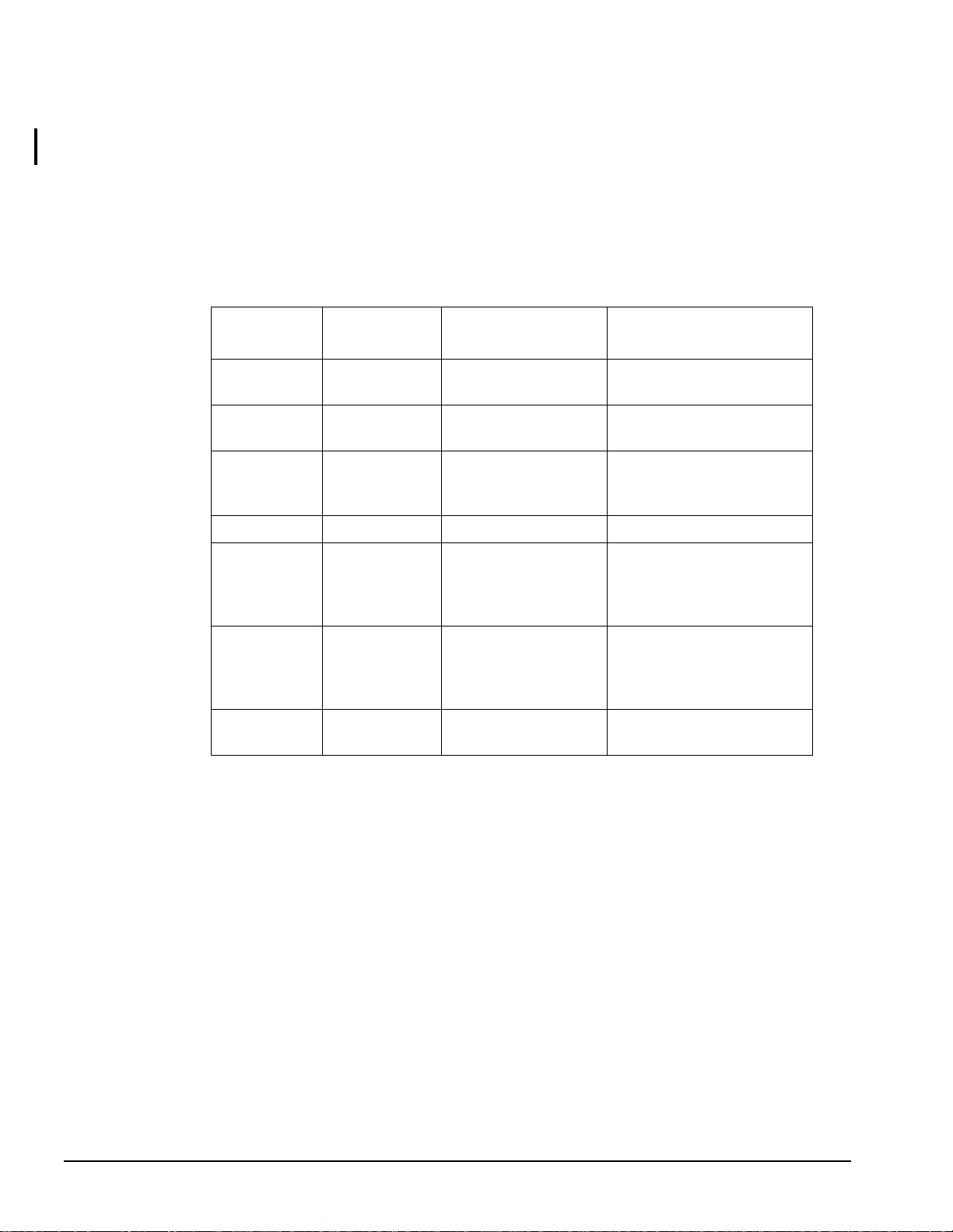
EISA Module
The Model 748 is available with a 4-slot EISA module. Table 1-26 shows the
EISA accessory cards that are supported. In addition, the EISA module also supports the HP
Human Interface Link (HP-HIL). However, HP-HIL devices are no longer offered by HP.
Page 37

General Information
Model 748 Ruggedized Workstation
NOTE: Only one of the Human I nterfaces (HP-HIL or PS/2) can be used at a time . Use of one i nterface
excludes the other interface.
Table 1-26 Supported EISA Accessory Cards
Product
Number
HP 2070B Instrument HP-IB Up to 4
HP 20711 High-Speed Instrument HP-IB Up to 4
GPIO Interface Card 1
HP 25525B Differential SCSI Up to 4
HP 25560A HP-IB Host Adaptor 1
HP 25567B IEEE 802.3 Thin/AUI LAN Up to 4
HP J2159A PSI/X.25 Interface Up to 4
HP J2165A Token Ring 802.5 Up to 4
HP J2645AA 100VG-Any LAN Up to 4
HP J2802B HP ATM Adapter Card Up to 4
PCI Module The Model 748 is available with a module tha t prov ide s four slots for customer
Product Name
Quantity
Supported
Notes
provided PCI accessor y cards. The module sup por ts the +5 Vdc PCI bus sig nal ling card type.
VME Module A variety of VME accessory cards can be installed in the Model 748 ’s 8-slot
VME module (slots 3 through 8 are for add-on cards). The slots conform to the 6U form factor. Slot numbers are 8 through 1, top to bottom. The VME backplane provides an interconnect connector for the EISA module.
NOTE: A Model 743 or 744 must be installed in VME Slot 1 to provide VME Slot 1 controller
functions (bus arbitration) for any VME boards installed in VME slots 3 through 8.
1-29
Page 38

General Information
Model 748 Ruggedized Workstation
Model 748 Ruggedized Workstation Functional Description
The section that f ollows contai ns a b lock di agram of the Model 74 8 Ruggedi zed Workstation
and describes EISA bus performance.
EISA Bus Performance
Block Diagram
The ideal slave read/write transfer rate is 25/25 MB/sec.
Figure 1-8 shows the functional architecture of the Model 748 workstation.
Figure 1-8 Model 748 Functional Block Diagram
1-30
Page 39

Environmental Specifications for Monitors
This section describes the environmental specifications for the HP D2806A, HP A4490D,
and HP A4331A/D color monitors.
Table 1-27 lists the operating, non-oper ating or storage, and re commended specifications for
altitude, humidity, and temperature for the monitors.
Table 1-27 Environmental Specifications for Monitors
Environmental Condition Specification
Altitude, non-operating 15,240 m (49,530 ft.)
General Information
Model 748 Ruggedized Workstation
Altitude, operating
Humidity, nonoperating or storage 5% to 95% RH
Humidity, operating 10% to 80 % RH
Humidity, recommended operating at 22 Deg C Non-condensing RH
Temperature, nonoperating or storage -40 Deg C to 60 Deg C
Temperature, operating 0 Deg C to 40 Deg C
Temperature, recommended operating 10 Deg C to 40 Deg C
a.Temperature derating above 2,500-m (8,000 ft.): 1.1 degrees C for
each 1,000 feet above 7,500 feet.
3,658 m (11,888 ft.)
a
1-31
Page 40

General Information
Model 748 Ruggedized Workstation
Original Equipment Manufacturer (OEM) Support Overview
The sections that follow describe standard OEM support and additional OEM support.
Standard Support
OEMs may obtain the following standard hardware and software support through their local
Hewlett-Packard Sales and Service Office:
• Customer support programs for servicing Hewlett-Packard products
• System/product hardware/software configurations
• System support options, including the following:
• HP SupportLine electronic support
• License to use software updates
• Media and document updates
• On-site response
Additional OEM Support Programs
Contact your Hewlett-Packard OEM Sales Representative regarding the availability of the
following OEM support:
• Detailed product qualification programs information
• Drawings: electrical and mechanical
• Engineering consulting time
• Hewlett-Packard specifications for products
• Peripheral device specifications
• Product component lists and specifications
1-32
Page 41

2
References
This chapter lists the title s and part numbers for hardware and software manuals associated
with the Model 743/744 and Model 748.
2-1
Page 42

References
HP Hardware Manuals
This section contains tables listing the hardware installation guides, service manuals, and
diagnostic manuals for the Model 743/744 and Model 748.
Installation Guides
Table 2-1 lists the hardware installation guides available for the Model 743 and Model 748.
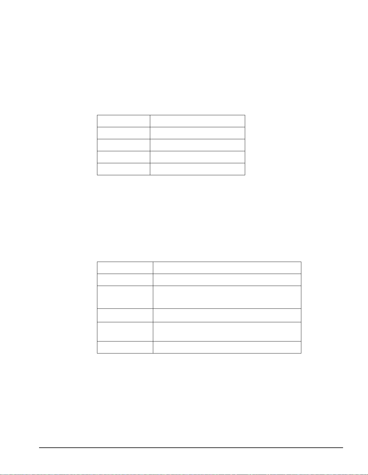
Table 2-1 System Installation/Owner’s Manuals
Manual Title Part N umber
HP Model 743 VMEbus Board Computer Owner’s Guide A2636-90603
HP Model 744 VMEbus Board Computer Owner’s Guide A4511-90606
HP Model 748 Workstation Owner’s Guide A4511-90604
Service Manuals
Table 2-2 lists the hardware service manuals available for the Model 743/744 and Model
748.
Table 2-2 Related Service Manuals
Manual Title
HP Model 743 VMEbus Board Computer A2636-90604
HP Model 748 A4511-90605
HP Model 744 A4511-90603
Part
Number
2-2
Page 43

Diagnostic Manuals
Table 2-3 lists the hardware diagnostic manuals available for the Model 743/744 and Model
748.
Table 2-3 Diagnostic Manuals
PA-RISC Support Tools Manual Licensed Users Volume 1, SPU 5960-3149
References
Manual Title Part Number
PA-RISC Support Tools Manual Licensed Users Volume 2, Device
Adapters/MUXes
PA-RISC Support Tools Manual Licensed Users Volume 3, LAN 5960-3153
PA-RISC Support Tools Manual Licensed Users Volume 4, SCSI 5960-3155
PA-RISC Support Tools Manual Licensed Users Volume 5, Disks 5960-3157
PA-RISC Support Tools Manual Licensed Users Volume 6, Tapes/
Printers
PA-RISC Support Tools Manual Licensed Users Volume 7, Utilities 5960-3161
PA-RISC Support Tools Manual Licensed Users Volume 8, ISL Sup-
port Tools
PA-RISC Support Tools Manual for HP Employees 5960-3165
Support Tools Manager User’s Manual; HP 9000 Series 700 and 800 5961-1612
HP Apollo 9000 Series 700 Diagnostics Manual, Volume 1 09740-90041
HP Apollo 9000 Series 700 Diagnostics Manual, Volume 2 09740-90043
HP Apollo 9000 Series 700 Support Tape/CD-ROM User’s Manual B2380-90000
5960-3151
5960-3159
5960-3163
2-3
Page 44

References
HP Software Manuals
This section contains tables listing the software system usage manuals and development
manuals for the Model 743/744 and Model 748.
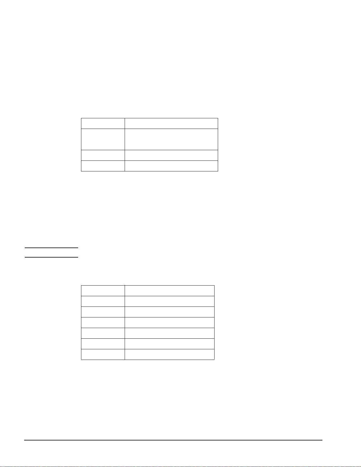
Table 2-4 lists the software system usage manuals available for the Model 743/744 and
Model 748.
Table 2-4 System Usage Manuals
HP-RT System Administration Tasks B5487-90002
VME Backplane Networking System Administration Guide B5489-90001
Table 2-5 lists the software development manuals available for the Model 743/744 and
Model 748.
Manual Title Part Number
Table 2-5 Software Development Manuals
Manual Title Part Number
HP-UX 9.05 Device Drivers A2636-90020
VME Services HP-UX 10 A4412-90022
Driver Writing in the HP-RT Environment B5487-90003
2-4
Page 45

3
Quality
The Quality Chapter discusses safety compliance programs, electromagnetic compatibility
programs, climatic and dynamic environmental tests, acoustics levels, statistical reliability,
and manufacturing quality programs.
3-1
Page 46

Quality
Safety Compliance Programs
Safety Compliance Programs
The sections that follow describe the Underwriter’s Laboratories, Canadian Standards Association, and TUV Rheinland programs.
Introduction
Models 743, 744, and 748 are designed, man ufa ct ured, and marketed in compliance wit h t he
published safety standards stated below. Validation testing was done with one unit representative of the product shipp ed to the custo mer. Contin ued compli ance is measure d by period ic
regulatory audits; pr oduc ti on un it s ar e t es te d for each audit. Models 743, 744, and 748 are in
compliance with adopted safety standards issued by the following standards bodies:
• Underwriter's Laboratories (USA)
• Canadian Standards Associa ti on (Cana da)
• TUV Rheinland (Germany)
The sections that follow explain each standard.
Underwriter’s Laboratories (USA)
• UL Standard 1950 Information Technology Equipment
As evidence of UL's listing, the products are marked with the UL listing mark.
Canadian Standards Association (Canada)
• CSA Standard 22.2 No. 950 Safety of Information Technology Equipment including
Electronic Business Equipment
As evidence of CSA's certification, the products are marked with the CSA monogram.
TUV Rheinland (Germany)
• Standards:
• Safety - EN60950 Safety of Informa tion Tec hnol ogy Equi pment inc lud ing Electronic
Business Equipment; International Electrotechnical Commission, Publication 950
• Ergonomics - ZH1/618 Sa fe ty Re gul at ion s f or Dis pla y Work Places in the Offi ce Sec tor
As evidence of TUV's certification, the products are marked with the TUV GS mark.
3-2
Page 47

Quality
Electromagnetic Compatibility Programs
Electromagnetic Compatibility Programs
The sections that follow discuss the Federal Communications Commission, European Community, and Voluntary Control Council for Interface standards bodies.
Introduction
Models 743, 744 and 748 comply with published standards for Electromagnetic Compatibility (EMC). In general, testi ng to required standards was performed using statistically significant quantities of typical Models 743, 744 and 748 configurations representative of the
product shipped to customers. These tests’ statistical basis demonstrates that with 80% confidence, at least 80% of the production population meets the specified margins to each standard. Additional conf ig ura ti ons ar e al so t es te d t o r edu ce the probability tha t non- con for ming
configurations exist. Continued compliance is measured by periodic regulatory audits; production units are tested for each audit. The Models 743, 744 and 748 are in compliance with
adopted EMC standards issued by the following standards bodies:
• Federal Communications Commission (USA)
• European Community
• Voluntary Control Council for Interference (Japan)
Federal Communications Commission (USA)
• Compliance Date: 6 November 1992 (dat es of subs eque nt r evi si ons available upon request)
• Self-Certified to 47 CFR (Code of Federal Regulations), parts 2 and 15, Class A
As evidence of compliance, products are marked with the FCC A statement.
European Community
• Compliance Date: 6 November 1992 (dat es of subsequent revisions av ai lab le upon request)
• Compliant to the EMC Directi ve 89/33/EEC and 92/31/EEC for I nformation Technology Equipment (ITE) per EN55022, and for Industrial, Scientific, and Medical Equipment (ISM) per EN55011
As evidence of compliance, produc ts are marked with the CE mark, and the product manual s
include a Declaration of Conformity.
Voluntary Control Council for Interference (Japan)
• Compliance Date: 9 December , 1992. (dates of subs equent revisions available upo n request)
• Registered to VCCI as a Class A product, according to CISPR 22
As evidence of compliance, products are marked with the VCCI statement.
3-3
Page 48

Quality
Electromagnetic Compatibility Programs
Overview
The sections that follow summarize the Electromagnetic Compatibility Programs. The following is a list of those programs:
1 Electromagnetic field emissions test suite
• Radiated emissions (Table 3-1)
• Conducted emissions (Table 3-2)
• Magnetic emissions (Table 3-3 and Table 3-4)
2 Electromagnetic field immunity /susceptibility test suite
• Electro-Static discharge field immunity (Table 3-5)
• Radiated field immunity (Table 3-6)
• Magnetic field immunity (Table 3-7)
3 Line transients immunity/susceptibility test suite
• Electrical fast transients (Table 3-8)
• Surge transients (Table 3-9)
• Conducted immunity (Table 3-10)
• Line sag (Table 3-11) Line surge (Table 3-12)
• Line blackout/dropout (Table 3-13)
• Line brownout (Table 3-14)
• Line brownout/recovery (Table 3-15)
Electromagnetic Field Emissions Test Suite
This section summarizes the Electromagnetic Field Emissions Test Suite.
Table 3-1 summarizes the radiated emissions tests during operating.
Table 3-1 Radiated Emissions Tests During Operation
Standard Level
EN55011 (ISM) CISPR 11 class A
EN55022 (ITE) CISPR 22 class A
FCC CFR 47 parts 2 and 15 FCC Class A
VCCI class A CISPR 22 class A
Table 3-2 summarizes the conducted emissions tests during operation.
Table 3-2 Conducted Emissions Tests During Operation
Standard Level
EN55011 (ISM) CISPR 11 class A
EN55022 (ITE) CISPR 22 class A
3-4
Page 49

Electromagnetic Compatibility Programs
Table 3-2 Conducted Emissions Tests During Operation
Standard Level
FCC CFR 47 parts 2 and 15 FCC Class A
VCCI class A CISPR 22 class A
Table 3-3 summarizes the magnetic emissions tests while the equipment is not operating.
Table 3-3 Magnetic Emissio ns Tests While Non-Operating
Standard Level
Quality
HP Standard 765.0 06 complies with CFR49
IATA Dangerous Goods Regulations, 30ed
<2 milligauss at 2.1 m
Table 3-4 summarizes the magnetic emissions tests during operation.
Table 3-4 Magnetic Emissions Tests During Operation
Standard Level
HP Standard 765.007 < 5 gauss p-p
Electromagnetic Field Immunity/Susceptibility Test Suite
This section summarizes the Field Immunity/Susceptibility Test Suite.
NOTE: All tests in this suite were performed while the product was operating.
Table 3-5 summarizes the electro-static discharge field immunity tests.
Table 3-5 Electro-Static Discharge Field Immunity
Standard Level
HP Standard 765. 002 15 KV A.D. (operating)
IEC 801-2 level 2 4 KV C.D., 8 KV A.D.
prEN50082-2 (ISM) 4 KV C.D., 8 KV A.D.
prEN55024-2 (ITE) 3 KV C.D., 8 KV A.D.
Table 3-6 summarizes the radiated field immunity test.
Table 3-6 Radiated Field Immunity
Standard Level
prEN55024-3 (ITE/ISM 3 V/m (IEC 801-3 level2)
3-5
Page 50

Quality
Electromagnetic Compatibility Programs
Table 3-7 summarizes the magnetic field immunity tests.
Table 3-7 Magnetic Field Immunity
Standard Level
HP Standard 765.001 317 A/m
IEC 801-8 level 5 100 A/m
Line Transients Immunity/Susceptibility Test Suite
This section summarizes the Line Transients Immunity/Susceptibility Test Suite.
NOTE: All tests in this suite were performed while the product was operating.
Table 3-8 summarizes the electrical fast transients test.
Table 3-8 Electrical Fast Transients
Standard Level
prEN55024-4 (ISM) 2 KV mains, 1 KV I/O ports
Table 3-9 summarizes the surge transient s tests.
Table 3-9 Surge Transients
Standard Level
HP Standard 765.003 1 KV DM/CM high energy transient
HP Standard 765.003 1 KV DM/CM low energy transient
HP Standard 765.003 3 KV peak DM/CM low energy ring wave
IEC 801-5 level 3 1 KV DM, 2KV CM
Table 3-10 summarizes the conducted immunity test.
Table 3-10 Conducted Immunity
Standard Level
EN55082-1, IEC801-6, level 2 3 V rms
Table 3-11 summarizes the line sag test.
Table 3-11 Line Sag
Standard Level
HP Standard 765.003 500 ms, 33% sag
3-6
Page 51

Table 3-12 summarizes the line surge test.
Table 3-12 Line Surge
Standard Level
HP Standard 76 5.003 500 m s , 25% surge
Table 3-13 summarizes the line blackout/dropout test.
Table 3-13 Line Blackout/Dropout
Standard Level
HP Standard 765.003 20 ms
Table 3-14 summarizes the line brownout test.
Table 3-14 Line Brownout
Standard Level
Quality
Electromagnetic Compatibility Programs
HP Standard 765.003 Minimum rated line voltage to 0 V in 30 minutes.
Table 3-15 summarizes line brownout/recovery test.
Table 3-15 Line Brownout/Recovery
Standard Level
HP Standard 765.003 0 V to minimum rated line voltage in 30 minutes.
3-7
Page 52

Quality
Climatic and Dynamic Environmental Ruggedness
Climatic and Dynamic Environmental Ruggedness
The sections that follow summarize the climatic and dynamic environmental tests suites.
Introduction
Models 743, 744 and 748 are designed for use in an environment that involves moderately
high and low temperatures, humidity variations, and occasional vibration. Many of the test
limits the workst at ions are subjected t o dur ing development are more severe than t hose documented.
The tests were developed to cause product failure so that product weaknesses are identified,
understood, and eliminated, when possible and to provide greater assurance of long-term
compliance to product specifications.
An effective qualification program establishes appropriate assurances. Our development and
manufacturing process capabilities are well understood.
Significant quantities of Models 743, 744, and 748 were tested prior to release for volume
production. Representative samples of customer-shippable workstations were tested in various configurations through the environmental tests to evaluate corner-case conditions.
NOTE: Presentation of these test suites does not imply a guarantee of product performance, nor a
guarantee of performance to these levels by the entire populat ion of Models 743, 744, an d 748
computer systems.
Overview
The following is a list of the clim at ic an d envi ronmental ruggedness test s sui t es su mmar i zed
in this section:
1 Temperature, humidity, and altitude test suite
• Temperature (Table 3-16 and Table 3-17)
• Humidity (Table 3-18 and Table 3-19)
• Altitude (Table 3-20 and Table 3-21)
2 Vibration and shock test suite
• Vibration (Table 3-22 )
• Shock (Table 3-23 and Table 3-24)
3-8
Page 53

Climatic and Dynamic Environmental Ruggedness
Temperature, Humidity, and Altitude Test Suite
Table 3-16 and Table 3-17 summarize the temperature tests suite.
Table 3-16 Temperatu re Tests While Non-Operations
Standard Level
HP class B1 (IEC 654 Part 1 class C3 compatible) -40 Deg C to 71 Deg C
Table 3-17 Temperature Tests During Operation
Standard Level
Quality
(-40 Deg F to 159.8
Deg F)
HP class B1
(IEC 654-1 class Bx compatible)
Temperature slew rate
(exceeds IEC 654-1)
0 Deg C to 55 Deg C (41 Deg F to 131 Deg F)
10 Deg C/minute (50 Deg F/minute)
Table 3-18 and Table 3-19 summarize the humidity tests suite.
Table 3-18 Humidity Tests While Non-Operational
Standard Level
HP class B 90% relative humidity at 65 Deg C
Table 3-19 Humidity Tests During Operation
Standard Level
Condensation <5 minutes recovery
HP class B 15% to 95% relative humidity at 40 Deg C
Table 3-20 and Table 3-21 summarize the altitude test suite.
Table 3-20 Altitude Tests While Non-Operating
Standard Level
HP Standard 761 (class B) (exceeds IEC 654-1) 4.6 Km (15 Kft)
Table 3-21 Altitude Tests During Operation
Standard Level
HP Standard 761 (class B) (exceeds IEC 654-1) 4.6 Km (15 Kft)
3-9
Page 54

Quality
Climatic and Dynamic Environmental Ruggedness
Table 3-22 summarizes the vibration tests suite.
Table 3-22 Vibration Tests While Non-Operating
Standard Level
HP Standard 759 (class B1)(exceeds IEC 654-3/VH2)
Packaging tests
HP Standard 762
Packaging tests
HP Standard 762
Table 3-23 and Table 3-24 summarizes the shock tests suite.
Table 3-23 Shock Tests While Non-Operational
Standard Level
Bump test
HP Standard 760 (class B)
Packaging drop test
HP Standard 762
IEC 654-3
Table 3-24 Shock Tests During Operation
2
7.4 m/s
swept sine
2
4.9 m/s
swept sine
2
0.015 g
random
> 294 m/s
2
(>30g) trapezoidal wave
.61 meters (24 inches)
(0.75 g 0-p)
(0.5 g 0-p)
/Hz (.3 g rms)
Standard Level
HP Standard 760 ( class B), IEC 654-3 150 cm/s < 3ms 1/2 half sine
3-10
Page 55

Acoustics
This section summarizes the sound power level test suite.
Sound Power Levels
Table 3-25 summarizes the sound power level test suite. Sound power levels are
A-weighted for these tests.
Table 3-25 Sound Power Levels
Standard Level
Quality
Acoustics
Equipment Under Test
Conditions, Procedures, and
Measurements
(Acceptance Criteria)
HP Environmental
tests, Section 767
Model 748: 6.22 Bels Fan(s) operating at high speed.
Model 748: 5.72 Bels Fan(s) operating at low speed.
3-11
Page 56

Quality
Statistical Reliability
Statistical Reliability
The sections that follow explain the Annualized Failure Rate (AFR) and the Mean Time
Between Failure (MTBF) computations.
Annualized Failure Rate Projections
Estimated AFR is based on a parts count and the failure rates of those parts in similar products. The AFR is estimated from the sum of the failure rates of the components’ assemblies.
A key assumption is that AFR is constant beyond the early life of the product and before
long-term wear out.
Projected Failure Rat e is th e mature AFR, esti mated fr om the fail ure ra tes of the compon ents
of the product. The "E stima ted Long -Term Ann ualiz ed Fail ure Rat e" is a futu re proj ecti on of
an average realist ic fa ilure rate be yond the typi cal in fa nt fai lure pe riod th at occu rs i n the fi rst
few months of use and before long-term wear out, which occurs after many years of use.
Mean Time Between Failure Computations
The MTBF is the reciprocal of the AFR. MTBF uses the following two units of time:
• Annualized MTBF (A-MTBF), the time units are years, or annually.
• Hourly MTBF (H-MTBF), the time unit is the hour.
This is derived by fac to ri ng ou t t h e AFR' s a nnua li zed percentage, then finding its recipro cal .
A resultant A-MTBF term is in years.
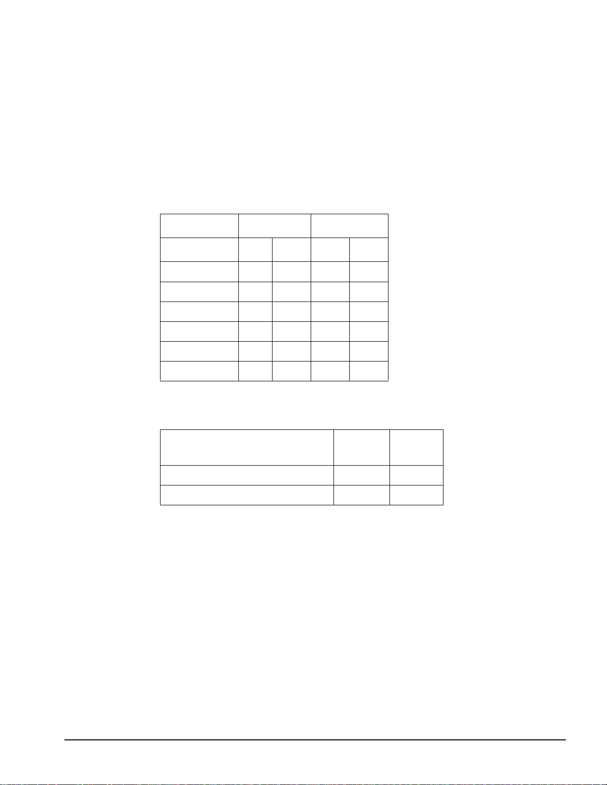
Table 3-26 MTBF Example
Model 744 VME board computer with graphics 4.8%/year
Add one 32MB RAM card 0.72%/year
Total 5.5%/year
Example AFR
1
= 159,381 hours
0.055 / 8766 hours
3-12
Page 57

Quality
Statistical Reliability
The H-MTBF numbers in the following tables are rounded to the nearest 100 hours.
Table 3-27 Model 748 Ruggedized Workstation With Model 743 CPU AFR Projections (%/Year)
Projected
Hardware Configurations
AFR (%/Yr.)
743 VME Board Computer, 32 MB RAM (two 16 MB cards), no
on-board graphics
Option 64 MB RAM card (one card using 16 Mbit DRAM)
8-Plane Color Graphics (GSC mezzanine card)
11.5
1.5
1.7
Table 3-28 Model 748 Ruggedized Workstation With Model 744 CPU AFR Projections (%/Year)
Projected
Hardware Configurations
744 VME Board Computer, 32 MB RAM, EISA Tray, 2.0-GB
FWD SCSI Disk, 17-inch Monitor
Option 64 MB RAM card (one card using 16 Mbit DRAM)
HCRX 8-Plane Graphics
AFR (%/Yr.)
11.8
1.23
1.38
Table 3-29 Model 743 VME Board Computer AFR Projections (%/Year)
Hardware Configurations
Projected
AFR (%/Yr.)
743 VME Board Computer, no graphics 3.1
743 VME Board Computer, and on-board 8-plane color graphics 3.8
Memory 8 MB RAM card (one card using 4 Mbit DRAM)
16 MB RAM card (one card using 4 Mbit DRAM)
32 MB RAM card (one card using 16Mbit DRAM)
64 MB RAM card (one card using 16Mbit DRAM)
Option 8-Plane Color Graphics (GSC mezzanine card)
HCRX-8
HCRX-24
ATM
PMC Bridge
PMC Bridge and Expander
0.6
1.2
0.7
1.5
1.7
1.38
1.54
2.0
2.0
3.0
3-13
Page 58

Quality
Statistical Reliability
Table 3-30 Model 744 VME Board Computer AFR Projections (%/Year)
Hardware Configurations
744 VME Board Computer with on-board graphics option 4.8
Memory 32 MB RAM card (one card using 16Mbit DRAM)
64 MB RAM card (one card using 16Mbit DRAM)
128 MB RAM card (one card using 64Mbit DRAM)
Option 8-Plane Color Graphics (GSC mezzanine card)
HCRX-8
HCRX-24
ATM
PMC Bridge
PMC Bridge and Expander
Projected
AFR (%/Yr.)
0.7
1.23
2.1
1.7
1.38
1.54
2.0
2.0
3.0
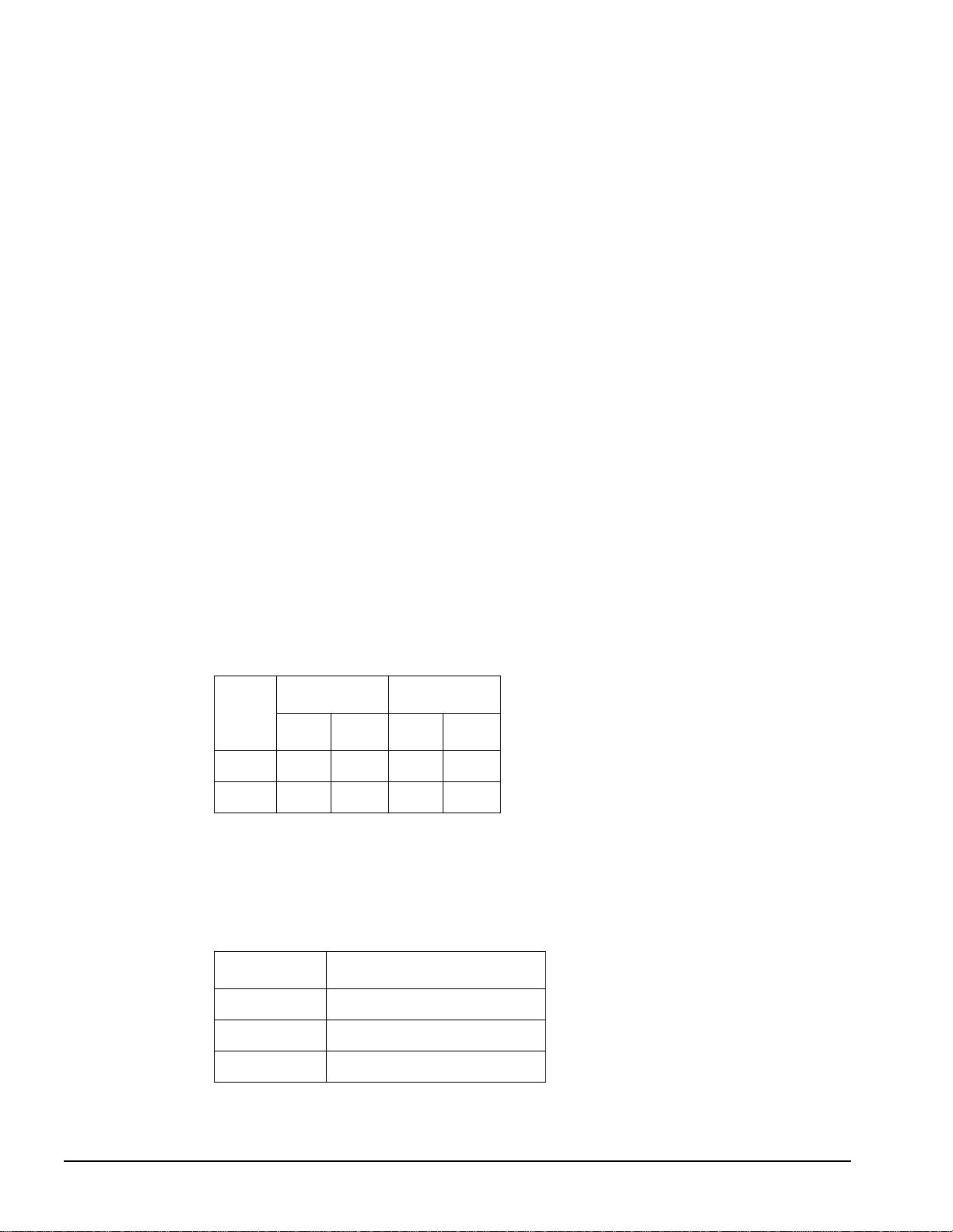
Table 3-31 summarizes the MTBF for the Model 743.
.
Table 3-31 Model 743 VME Board Computer MTBF (hr-MRBF) Computations
Hardware
(Includes Model 743 VME Board
Computer)
16 MB RAM (one 16 MB
card using 4 Mbit DRAM)
32 MB RAM (one 32 MB
card using 16Mbit DRAM)
64 MB RAM (one 64 MB
card using 16 Mbit DRAM)
128 MB RAM (two 64 MB
cards using 16 Mbit
DRAM)
256 MB RAM (four 64 MB
cards using 16 Mbit
DRAM)
No On-Board
Graphics
MTBF (Hours)
186,000 160,000
210,000 177,800
173,900 153,800
131,100 117,600
87,900 81,600
On-Board
Graphics
MTBF (Hours)
3-14
Page 59

4
Mechanical Information
This chapter contains mechanical information about the components of the Model 743 and
Model 744 VME Board Computers and the Model 748 Ruggedized Workstation. Included is
air flow requirements, interface connector manufacturing data, system board and accessory
card dimensions, chassis and module dimensions and weights, mounting and support, and
mechanical drawings.
4-1
Page 60

Mechanical Information
Model 743 and Model 744 VME Board Computers
Model 743 and Model 744 VME Board Computers
Key Components
Figure 4-1 shows key components on the Model 743 VME Board Computer.
PCMCIA Connector
GSC Bus Connector
VME Controller
CPU (under heatsink)
RAM Card Connectors
I/O Controller
Boot ROM
EEPROM
Video RAM
(optional onboard
graphics)
RAM Card Connectors
Optional Onboard
Graphics Controller
Figure 4-1 Model 743 Key Components
4-2
Page 61
Mechanical Information
Model 743 and Model 744 VME Board Computers
Figure 4-2 shows key components on the Model 744 VME Board Computer.
EEPROM
IODC
PDC
VME Controller
Audio CODEC
PCMCIA Connector
Optional Onboard
Graphics Controller
GSC Bus Connector
CPU (under heatsink)
RAM Card Connectors
I/O Controller
Video RAM
(optional onboard graphics)
Figure 4-2 Model 7 44 Key Component s
4-3
Page 62

Mechanical Information
Model 743 and Model 744 VME Board Computers
Air Flow Requirements
The air flow requirements for the Model 743 and Model 744 are as follows:
46 linear meters (150 linear feet) per minute, -5 Deg C to 35 Deg C (23 Deg F to 95 Deg F)
61 linear meters (200 linear feet) per minute, 35 Deg C to 55 Deg C (95 Deg F to 151 Deg F)
NOTE: Model 743 and Model 744 VME Board Computers are to be operated only in an envir onment
that is free from conductive pollution, including dry non-conductive pollution which could
become conductive due to expected condensation.
CAUTION: Integrated circuit case and junction temperatures must not exceed those shown in
Figure 4-3 and Figure 4-4.
Figure 4-3 Model 743 Integrated Circuit Case Temperature Limits
4-4
Page 63

T
= 85
j
Tj = 100
T
= 75
c
Mechanical Information
Model 743 and Model 744 VME Board Computers
T
= 95 (744/132L)
j
= 102 (744/165L)
T
= 85
j
= Maximum junction temperature in degrees centigrade
T
j
= Maximum case temperature in degrees centigrade
T
c
Figure 4-4 Model 744 Integrated Circuit Case Temperature Limits
4-5
Page 64

Mechanical Information
Model 743 and Model 744 VME Board Computers
Interface Connectors
Table 4-1 lists the interface connector manufacturing data.
Table 4-1 Interface Connector Manufacturing Data
Connector
Audio ITT Canon MDSM-9PE-Z10 or equivalent
HP Parallel ITT Canon MDSM-25PE-Z10 or equivalent
Mouse/Keyboard AMP 750071-1 or equivalent
P1 AMP 215606-4 or equivalent
P2 AMP 650988-0 or equivalent
SCSI II AMP 749830-5 or equivalent
Serial ITT Canon MDSM-18PE-Z22 or equivalent
Speaker Hosiden HSJ3062-01-410 or equivalent
Video/LAN ITT Canon MDSM-30PE-z10 or equivalent
Manufacturing
Data
Manufacturing Part Number
4-6
Page 65

Mechanical Information
Model 743 and Model 744 VME Board Computers
Mechanical Dimensions
Figure 4-5 and Figure 4-6 show the dimensions of the Model 743 board computer.
Figure 4-5 Model 743 Board Computer
4-7
Page 66

Mechanical Information
Model 743 and Model 744 VME Board Computers
Figure 4-6 Model 743 Board Computer (Continued)
4-8
Page 67
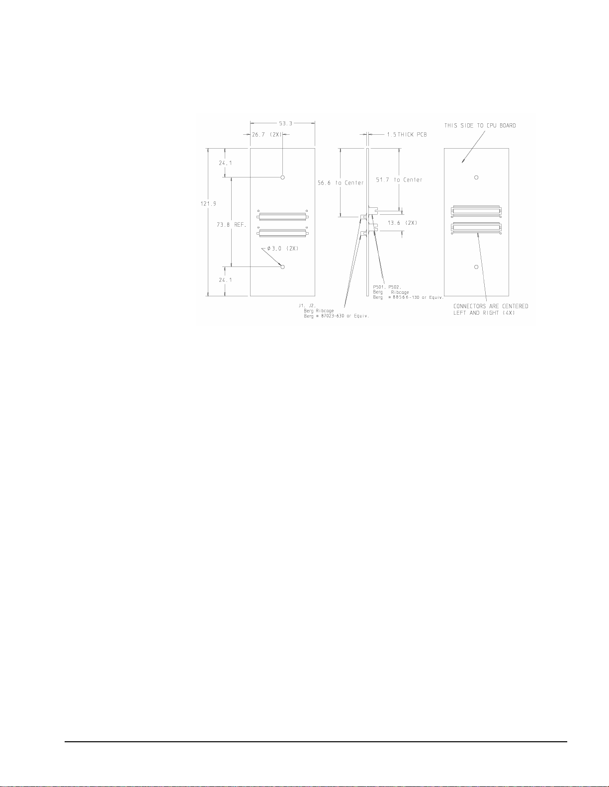
Model 743 and Model 744 VME Board Computers
Figure 4-7 shows the dimensions of a Model 743 RAM card.
Mechanical Information
Figure 4-7 Model 743 RAM Card
4-9
Page 68

Mechanical Information
Model 743 and Model 744 VME Board Computers
Figure 4-8 through Figure 4-12 show the dimensions of the Model 744 system board.
Figure 4-8 Model 744 Board Computer
4-10
Page 69

Mechanical Information
Model 743 and Model 744 VME Board Computers
Figure 4-9 Model 744 Board Computer (Continued)
4-11
Page 70

Mechanical Information
Model 743 and Model 744 VME Board Computers
Figure 4-10 Model 744 Board Computer (Continued)
4-12
Page 71

Mechanical Information
Model 743 and Model 744 VME Board Computers
Figure 4-11 Model 744 Board Computer (Continued)
4-13
Page 72

Mechanical Information
Model 743 and Model 744 VME Board Computers
Figure 4-12 Model 744 Board Computer (Continued)
4-14
Page 73

Mechanical Information
Model 743 and Model 744 VME Board Computers
Figure 4-13 through Figure 4-15 show the dimensions of a Model 744 RAM card.
Figure 4-13 Model 744 RAM Card
Figure 4-14 Model 744 RAM Card (Continued)
4-15
Page 74

Mechanical Information
Model 743 and Model 744 VME Board Computers
Figure 4-15 Model 744 RAM Card (Continued)
4-16
Page 75

Model 743 and Model 744 VME Board Computers
Figure 4-16 shows the dimensions of a GSC+ accessory card.
Mechanical Information
Figure 4-16 GSC Accessory Card
4-17
Page 76

Mechanical Information
Model 743 and Model 744 VME Board Computers
Figure 4-17 shows the dimensions of the PMC Bridge Adapter.
Figure 4-17 PMC Bridge Adapter
4-18
Page 77

Model 743 and Model 744 VME Board Computers
Figure 4-18 shows the dimensions of the PMC Expansion Adapter.
Mechanical Information
Figure 4-18 PMC Expansion Adapter
4-19
Page 78

Mechanical Information
Model 748 Chassis and Modules
Model 748 Chassis and Modules
Figure 4-19 shows the dimensions of the Model 748 chassis.
Figure 4-19 Model 748 Main Chassis
4-20
Page 79

Model 748 Chassis and Modules
Figure 4-20 shows the dimensions of the Model 748 outside wall.
Mechanical Information
Figure 4-20 Model 748 Outside Wall
Figure 4-21 shows the dimensions of Model 748 center wall.
Figure 4-21 Model 748 Center Wall
4-21
Page 80

Mechanical Information
Model 748 Chassis and Modules
Figure 4-22 shows the dimensions of the Model 748 mass storage module chassis.
Figure 4-22 Model 748 Mass Storage Module Chassis
4-22
Page 81

Mechanical Information
Model 748 Chassis and Modules
Figure 4-23 shows the dimensions of the Model 748 VME module chassis.
Figure 4-23 Model 748 VME Module Chassis
4-23
Page 82

Mechanical Information
Model 748 Chassis and Modules
Figure 4-24 shows the dimensions of the Model 748 PCI/EISA module chassis.
Figure 4-24 Module 748 PCI/EISA Module Chassis
4-24
Page 83

Mechanical Information
Model 748 Chassis and Modules
Figure 4-25 shows the dimensions of the Model 748 EISA converter board.
Figure 4-25 Model 748 EISA Converter Board
Figure 4-26 shows the dimensions of the Model 748 PCI converter board.
Figure 4-26 Model 748 PCI Converter Board
4-25
Page 84

Mechanical Information
Model 748 Chassis and Modules
Figure 4-27 shows the dimensions of the Model 748 VME backplane board.
Figure 4-27 Model 748 VME Backplane Board
Figure 4-28 shows the dimensions of the Model 748 power distribution board.
Figure 4-28 Model 748 Power Distribution Board
4-26
Page 85

Model 748 Chassis and Modules
Weights
Table 4-2 lists the weights of the components of the Model 748 workstation.
Table 4-2 Weights of Model 748 Workstation Product and Modules
Mechanical Information
Part Name
Model 748 Ruggedized Workstation chassis including power distribution board,
on/off switch, and front cover (does not include modules or board computer)
SE Mass storage module including SCSI and power cables 2.03 Kg 4 lbs. 8.1 oz.
FWD Mass storage module including SCSI and power cables 2.25 Kg 5 lbs. 0 oz.
Disk drives (maximum weight) 0.95 Kg 2 lbs. 1.6 oz.
VME backplane 0.63 Kg 1 lb. 6.4 oz.
VME module (including six slot cover) 1.91 Kg 4 lbs. 4.0 oz.
VME module (without slot covers) 1.65 Kg 3 lbs. 10.4 oz.
VME slot cover 0.05 Kg 1.7 oz.
PCI/EISA module 1.13 Kg 2 lbs. 8.3 oz.
EISA converter board/backplane 0.47 Kg 1 lb. 0.7 oz.
PCI converter board/backplane 0.37 Kg 13.2 oz.
Power supply 3.43 Kg 7 lbs. 9.5 oz.
Model 743 Board Computer with on-board graphics (no other options) 0.47 Kg 1 lb. 0.7 oz.
Metric
Weight
9.50 Kg 21 lbs. 2.0 oz.
English
Weight
Model 744 Board Computer with on-board graphics (no other options) 0.62 Kg 1 lb. 1.7 oz.
Model 743 RAM card 0.05 Kg 1.6 oz.
Model 744 RAM card 0.05 Kg 1.6 oz.
GSC Expansion kit 0.17 Kg 6.1 oz.
PMC bridge board with mounting hardware (no blank bezels) 0.27 Kg 7.6 oz.
PMC expansion board with mounting hardware (no blank bezels or sleeves) 0.24 Kg 6.8 oz.
PMC blank bezels (each) 0.03 Kg 0.8 oz.
PMC ejector handle sleeves 0.02 Kg 0.7 oz.
GSC graphics card 0.10 Kg 3.6 oz.
GSC FWD SCSI card 0.11 Kg 3.8 oz.
HCRX/8 graphics card 0.27 Kg 7.7 oz.
HCRX/24 graphics card 0.29 Kg 8.4 oz.
GSC ATM card 0.14 Kg 4.0 oz.
4-27
Page 86

Mechanical Information
Model 748 Chassis and Modules
Mounting and Support
Each Model 748 workstatio n is sh ipp ed with a rack mount ki t incl uding flange s, spac ers, an d
screws. In this s ect ion, the term "bac k" refers to the ca bl e-out side of the workstation. Model
748 satisfies three rack mount orientations:
• Mast mount
• Rack mount, either front out or back out
Power switching is ac ce ssi bl e fr om bot h f ron t an d bac k. A si ngl e p ower L ED is o n th e fr ont .
Status and te st LEDs are l ocated on t he Mo del 743 Mode l 744 VME Boa rd Computer s. If the
power supply and VME board computer LEDs must be visible, mount the workstation back
out. Devices within the mass sto rage module ca n be arr anged for front or back a ccessi bility.
• Wall mount
PCI/EISA and VME card cages are fixed and cannot be reversed.
Mechanical Drawings
For OEMs that have signed a Hewlett-Packard non-disclosure agreement, the mechanical
drawings are available by request from the Workstation Systems Group through your
Hewlett-Packard OEM Sales Representative. These drawings are Hewlett-Packard confidential and cannot be redistributed.
When you ask for drawings, please specify the following:
• Drawing part number, size, and page number, if needed
• Name, assembly or subassembly
The drawings are sent to your Sales and Service Office.
Conversion Cables
All conversion cables are 762 plus or minus 30 mm (30 plus or minus 1.18 inch) long. The
end of the cable that connects to the board computer uses a micro D-sub male (MDSM) connector. The other end of the cable uses a standard D-sub or other connector.
4-28
Page 87

Chassis Parts and Models
Table 4-3 shows the as sembly group, included subass embl ies, and mechanical drawing reference number for the Model 748 chassis parts and modules.
Table 4-3 Mechanical Drawings for Chassis Parts and Modules
Mechanical Information
Model 748 Chassis and Modules
Assembly Group Included Subassemblies
Model 748 chassis Trim piece C-A2261-40019-10
Front bezel (cover) D-A2261-40003-10
Light pipe assembly D-A2261-40004-10
Removable wall C-A4309-00003-10
Left wall assembly C-A4309-00004-10
Chassis D-A4309-00011-10
Power distribution board D-A4309-66002-10
Mass storage module Tray D-A4309-00005-10
PCI/EISA module 4-slot chassis C-A4309-0001 0-1 0
VME module Card cage D-A4309-00006-10
Power supply module D-0950-2303-10
Model 743/744 system board Front panel D-A2636-00001-10
GSC expansion GSC video bulkhead C-A2636-00005-10
Subassembly Drawing
Number
Double-high bulkhead D-A2636-00002-10
GSC blank bulkhead C-A2636-00010-10
Blank VME bulkhead D-A2636-00004-10
Two-slot adapter board D-A2636-66012-10
PMC expansion PMC bridge adapter D-A4504-66001-10
PMC expansion adapter D-A4505-66002-10
4-29
Page 88

Mechanical Information
Model 748 Chassis and Modules
4-30
Page 89

5
Electrical Information
The Electrical Infor mation Cha pter co ntain s infor mation o n the connect or pino uts, re al-t ime
clock battery, and video output signal specifications.
5-1
Page 90

Electrical Information
The sections that follow contain figures and tables of the connector pinouts and the wiring
tables for video, audio, HP parallel, RS-232, AUI LAN, single-ended SCSI, FW SCSI, PS/2,
and VMEbus; specifications for the real-time battery clock, video output signals, and video
timing.
5-2
Page 91

Video Connector Pinouts
This section contains a figure of the video connector, a table of the video connector pinouts,
the HP4304A conversion video cable connectors diagrams, and the conversion video cable
wiring table.
Figure 5-1 illustr ates the vi deo conn ector pin lo catio ns for the Model 74 3 and Model 744 I/ O
backplane.
Figure 5-1 Video Connector
Electrical Information
Table 5-1 identifies the pins on the Model 743 and Model 744 I/O backplane video connector.
Table 5-1 Video Connector Pinouts
Pin
Number
1 GND / DDC 6 GND 11 GND / +5
2 GND 7 BLUE 12 GND
3 RED 8 GND 13 NC / SSYNC
4 GND 9 GND 14 GND
5 GREEN 10 HSYNC 15 VSYNC
Signal
743 / 744
Pin
Number
Signal
743 / 744
Pin
Number
Signal
743 / 744
5-3
Page 92

Electrical Information
Figure 5-2 illustrates the connector pin locations on each end of the HP A4304A conversion
video cable.
Figure 5-2 HP A4304A Conversion Video Cable Connectors
Table 5-5 identifies HP A4304A conversion video cable pins.
Table 5-2 A4304A Conversion Video Cable Wiring Table
15-Pin MDSM 15-Pin D-Sub
Pin 1
Pin 2
Pin 3 Pin 1
Pin 4 Pin 6
Pin 5 Pin 2
Pin 6 Pin 7
Pin 7 Pin 3
Pin 8 Pin 8
Pin 9 Pin 10
Pin 10 Pin13
5-4
Pin 11
Pin 12
Pin 13
Pin 14
Pin 15 Pin 14
Page 93

Electrical Information
Figure 5-3 illustrates the connector pin locations on each end of the HP A4223A conversion
video cable.
Figure 5-3 HP A4223A Conversion Video Cable Connectors
Table 5-3 identifies HP A4223A conversion video cable pins.
Table 5-3 A4223A Conversion Video Cable Wiring Table
15-Pin MDSM 15-Pin D-Sub
Pin 1 Pin 12
Pin 2
Pin 3 Pin 1
Pin 4 Pin 6
Pin 5 Pin 2
Pin 6 Pin 7
Pin 7 Pin 3
Pin 8 Pin 8
Pin 9 Pin 10
Pin 10 Pin13
Pin 11 Pin 9
Pin 12
Pin 13
Pin 14
Pin 15 Pin 14
5-5
Page 94

Electrical Information
Figure 5-4 illustrates the connector pin locations on each end of the HP A4305A conversion
video cable.
PIN 15
PIN 9
PIN 8
PIN 1
WIRING DIAGRAM
1
2
3
4
5
6
7
8
9
10
11
12
13
14
15
OUTER SHELL
1
2
3
4
5
6
7
8
9
10
11
12
13
14
15
16
17
18
19
20
21
22
23
24
25
26
27
28
29
30
C1
C2
C3
C4
C5
C2
C1
PIN 10
PIN 1
PIN 11
1.8K Resisto r
Figure 5-4 HP A4305A Conversion Video Cable Connectors
Table 5-4 identifies HP A4305A conversion video cable pins.
Table 5-4 A4305A Conversion Video Cable Wiring Table
15-Pin MDSM 35-Pin EVC
C5
C4
C3
PIN 30
PIN 21
Pin 1 Pin 26
Pin 2 Pin 25
Pin 3 Pin C1
Pin 4 Pin C5
Pin 5 Pin C2
Pin 6 Pin C5
Pin 7 Pin C4
Pin 8 Pin C5
Pin 9 Pin 4
Pin 10 Pin 5
Pin 11 Pin 28
Pin 12
Pin 13
Pin 14
Pin 15 Pin 6
5-6
Page 95

Electrical Information
Figure 5-5 illustrates the connector pin locations on each end of the HP A4167A conversion
video cable.
PIN 15
Pin 6
Pin 11
PIN 9
Pin 15
Pin 10
PIN 8
Pin 1
PIN 1
Pin 5
WIRING DIAGRAM
1
2
3
4
5
6
7
8
9
10
11
12
13
14
15
OUTER SHELL
1
2
3
4
5
6
7
8
9
10
11
12
13
14
15
16
17
18
19
20
21
22
23
24
25
26
27
28
29
30
C1
C2
C3
C4
C5
C2
C1
PIN 10
PIN 1
PIN 11
Figure 5-5 HP A4167A Conversion Video Cable Connectors
Table 5-5 identifies HP A4167A conversion video cable pins.
Table 5-5 A4167A Conversion Video Cable Wiring Table
15-Pin D-Sub 35-Pin EVC
C5
C4
C3
PIN 30
PIN 21
Pin 1 Pin C1
Pin 2 Pin C2
Pin 3 Pin C4
Pin 4
Pin 5 Pin 25
Pin 6 Pin C5
Pin 7 Pin C5
Pin 8 Pin C5
Pin 9 Pin 28
Pin 10 Pin 4
Pin 11
Pin 12 Pin 26
Pin 13 Pin 5
Pin 14 Pin 6
Pin 15 Pin 27
5-7
Page 96

Electrical Information
Audio Connector Pinouts
This section contains a figure of the audio connector and a table of the audio connector
pinouts.
Figure 5-6 illustrates the audio connector pin locations.
Figure 5-6 Audio Connector
Table 5-6 identifies the audio connector pins.
Table 5-6 Audio Connector Pinouts
Pin
Number
1 Mic in GND
2 Line in left
3 Line in right
4 Headset right
5 Headset left
6 Mic in A
7Mic Vref
8 Line in GND
9 Headset GND
Signal
5-8
Page 97

Figure 5-7 illustrates the connector pin locations on each end of the HP A4302A conversion
audio cable.
Figure 5-7 HP A4302A Conversion Audio Cable Connectors
Electrical Information
5-9
Page 98

Electrical Information
HP Parallel Connector Pinouts
This section contains a figure of the HP parallel connector, a table of the HP parallel connector pinouts, the HP4 300A c onve rs ion HP parallel cable connectors diagrams, and t he conversion HP parallel cable wiring table.
Figure 5-8 illustrates the HP parallel connector pin locations.
Figure 5-8 HP Parallel Connector
Table 5-7 identifies the HP parallel connector pins.
Table 5-7 HP Parallel Connector Pinouts
Pin
Number
1STROBE14AFD
2 Data 0 15 ERROR
3Data 16INIT
4Data 17SCT IN
5 Data 18 GND
6 Data 19 GND
7 Data 20 GND
8 Data 21 GND
9 Data 22 GND
Signal
Pin
Number
Signal
5-10
10 ACK 23 GND
11 BUSY 24 GND
12 PE 25 GND
13 SLCT
Page 99

Electrical Information
Figure 5-9 illustrates the connector pin locations on each end of the HP A4300A conversion
HP parallel cable
Figure 5-9 HP A4300A Conversion HP Parallel Cable Connectors
Table 5-8 identifies the HP A4300A conversion HP parallel cable pins.
Table 5-8 Conversion HP Parallel Cable Wiring Table
25-Pin MDSM 25-Pin D-Sub 2 5-Pin MDSM 25-Pin D-Sub
Pin 1Pin 1Pin 14Pin 14
Pin 2Pin 2Pin 15Pin 15
Pin 3Pin 3Pin 16Pin 16
Pin 4Pin 4Pin 17Pin 17
Pin 5Pin 5Pin 18Pin 18
Pin 6Pin 6Pin 19Pin 19
Pin 7Pin 7Pin 20Pin 20
Pin 8Pin 8Pin 21Pin 21
Pin 9Pin 9Pin 22Pin 22
Pin 10 Pin 10 Pin 23 Pin 23
Pin 11 Pin 11 Pin 24 Pin 24
Pin 12 Pin 12 Pin 25 Pin 25
Pin 13 Pin 13
5-11
Page 100

Electrical Information
RS-232 Connector Pinouts
This section contains a figure of the RS-232 connector, a table of the RS-232 connector
pinouts, the HP 4301A conversion RS-232 cable connectors diagrams, and the conversion
RS-232 cable wiring table.
Figure 5-10 illustrates the RS-232 connector pin locations.
Figure 5-10 RS-232 Serial Connector
Table 5-9 identifies the RS-232 connector pins.
Table 5-9 RS-232-C Connector Pinouts
Pin
Number
1DCD 6DSR
2RXD 7RTS
3TXD 8CTS
4DTR 9RI
5 GND
Signal
Pin
Number
Signal
5-12
 Loading...