

Page 1
HP 9000 Model 742i
Owner's Guide
for HP-UX Users
HP 9000 Series 700i Industrial Workstations
ABCDE
HP Part No. A2260-90014
Printed in USA February 1993
Edition 1
E0293
FINAL TRIM SIZE : 7.0 in x 8.5 in
Page 2
Legal Notices
The information contained in this documen
t is sub ject to c
hange without
notice.
Hewlett-Packard makes no warranty of any kind with r
egard to this manual,
including, but not limited to, the implied warranties of merchantability and
tness for a particular purpose.
contained herein or direct, indirect, special, inciden
Hewlett-Packard shall not be liable for errors
tal or consequential damages
in connection with the furnishing, performance, or use of this material.
Warranty.
Agreement and Limited Warranty
Please read the enclosed
Hewlett-Packard SoftwareProduct License
before operating this product. Rights in the
software are oered only on the condition that the customer accepts all terms
and conditions of the License Agreement.
Operating the product indicates your acceptance of these terms and conditions.
If you do not agree to the License Agreemen
t, you may return the unused
product for a full refund.
A copy of the specic warranty terms applicable to your Hewlett-Packard
product and replacement parts can be obtained from your lo cal Sales and
Service Oce.
Copyrightc
1993 Hewlett-Packard Company
This document contains information which is protected by copyright. All rights
are reserved. Reproduction, adaptation, or translation without prior written
permission is prohibited, except as allowed under the copyrightlaws.
c
Copyrightc
AT&T, Inc. 1980, 1984, 1986. Copyright
Microsystems, Inc. Copyrightc
Inc. Copyrightc
Copyrightc
1985-1986, 1988 Massachusetts Institute of Technology.
1986 Digital Equipment Corp. Copyright
1980, 1984, 1986 UNIX System Laboratories,
1986, 1987, 1988 Sun
c
The Regents of the
University of California 1979, 1980, 1983, 1985.
FINAL TRIM SIZE : 7.0 in x 8.5 in
Page 3

This software and documentation is based in part on the F
Software Distribution under license from the Regen
ts of the University of
California.
ourth Berkeley
Restricted Rights Legend.
Use, duplication or disclosure by the U.S.
Government Department of Defense is subject to restrictions as set forth in
paragraph (b)(3)(ii) of the Righ
ts in Technical Data and Software clause in
FAR 52.227-7013.
FINAL TRIM SIZE : 7.0 in x 8.5 in
Page 4
Printing History
This manual's printing date and part n
printing date will change when a new edition is prin
made at reprint without changing the printing date. The man
will change when extensivechanges occur.
Manual updates ma
product changes. To ensure that you receive these updates or new editions,
you should subscribe to the appropriate pro duct support service. See y
Hewlett-Packard Sales Representative for details.
February, 1993 Edition 1
Hewlett-Packard Company
OSSD Learning Products
3404 East Harmony Road
Fort Collins, Colorado 80525
y be issued b et
umber show its current edition. The
ted. Minor changes maybe
ual part number
ween editions to correct errors or documen
our
t
iv
FINAL TRIM SIZE : 7.0 in x 8.5 in
Page 5
Safety Symbols and Conventions
The following conventions are used throughout this man
Note
Caution
Notes contain important information set o from the text.
Caution messages indicate pro cedures whic
could result in loss of data or damage to equipmen
ual:
h, if not observed,
t. Do not
proceed b eyond a CAUTION sign until the indicated conditions
are fully understood and met.
Warning
Warning messages indicate procedures or practices which, if
not observed, could result in personal injury. Do not proceed
beyondaWARNING sign until the indicated conditions are fully
understood and met.
FCC Statement (For U.S.A. Only)
The Federal Communications Commission (in Subpart J of Part 15, Do cket
20780) has sp ecied that the following notice be brough
t to the attention of the
users of this pro duct.
Warning.
This equipment generates, uses, and can radiate radio frequency
energy and if not installed and used in accordance with the instructions
manual, may cause interference to radio communications. It has been
tested and found to comply with the limits for a Class A computing device
pursuant to Subpart J of Part 15 of FCC rules, which are designed to provide
reasonable protection against suchinterference when operated in a commercial
environment. Operation of this equipment in a residential area is likely to
cause interference in which case the user at his own expense will b e required to
take whatever measures may be required to correct the interference.
FINAL TRIM SIZE : 7.0 in x 8.5 in
v
Page 6
Regulatory Information
FCC Statement(For U.S.A. Only)
The Federal Communications Commission (in Subpart J of P
20780) has sp ecied that the following notice be brough
art 15, Docket
t to the attention of
the users of this product:
This equipment generates, uses, and can radiate radio frequency energy
and if not installed and used in accordance with the instructions man
ual,
may cause interference to radio communications. It has been tested and
found to comply with the limits for a Class A computing device pursuan
tto
Subpart J of Part 15 of FCC rules, which are designed to provide reasonable
protection against suchinterference when op erated in a commercial
environment. Operation of this equipment in a residential area is likely to
cause interference in which case the user at his own expense will b e required
to take whatever measures may be required to correct the in
terference.
Turvallisuusyhteenveto (Finland Only)
Laserturvallisuus
Luokan 1 Laserlaite
Klass 1 Laser Apparat
HP 9000 Mo del 742i tietokoneeseen voidaan asentaa muistilaitteeksi
laitteensisainen CD-ROM-levyasema, joka on laserlaite. Talloin myos
paalaitteena toimiva tietokone katsotaan laserlaitteeksi.
Kyseinen CD-ROM-livyasema on kayttajan kannalta turvallinen luokan 1
laserlaite. Normaalissa kaytossa levyaseman suo jakotelo estaa lasersateen
paasyn laitteen ulkopuolelle.
HP 9000 Mo del 742i tietokoneen on tyyppihyvaksynyt Suomessa
laserturvallisuuden osalta Tyosuojeluhallitus, Tyosuojeluhallituksen
hyvaksyntanumero TSH 222/6019/90. Laitteiden turvallisuusluokkaon
maaritettyvaltioneuvoston paatoksen No: 472/1985 ja standardin SFS-IEC
825 mukaisesti. Tiedot CD-ROM-levyasemassa kaytettavan laserdio din
sateilyominaisuuksista:
Aallonpituus 780 nm
Teho 0,4 mW
Luokan 1 laser
vi
FINAL TRIM SIZE : 7.0 in x 8.5 in
Page 7
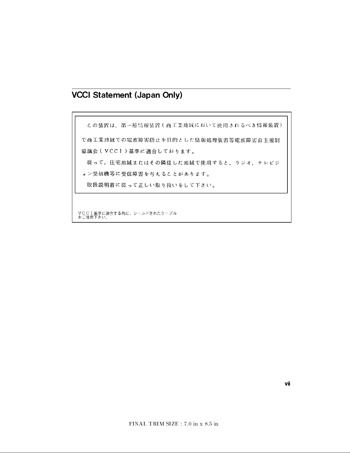
VCCI Statement (Japan Only)
FINAL TRIM SIZE : 7.0 in x 8.5 in
vii
Page 8
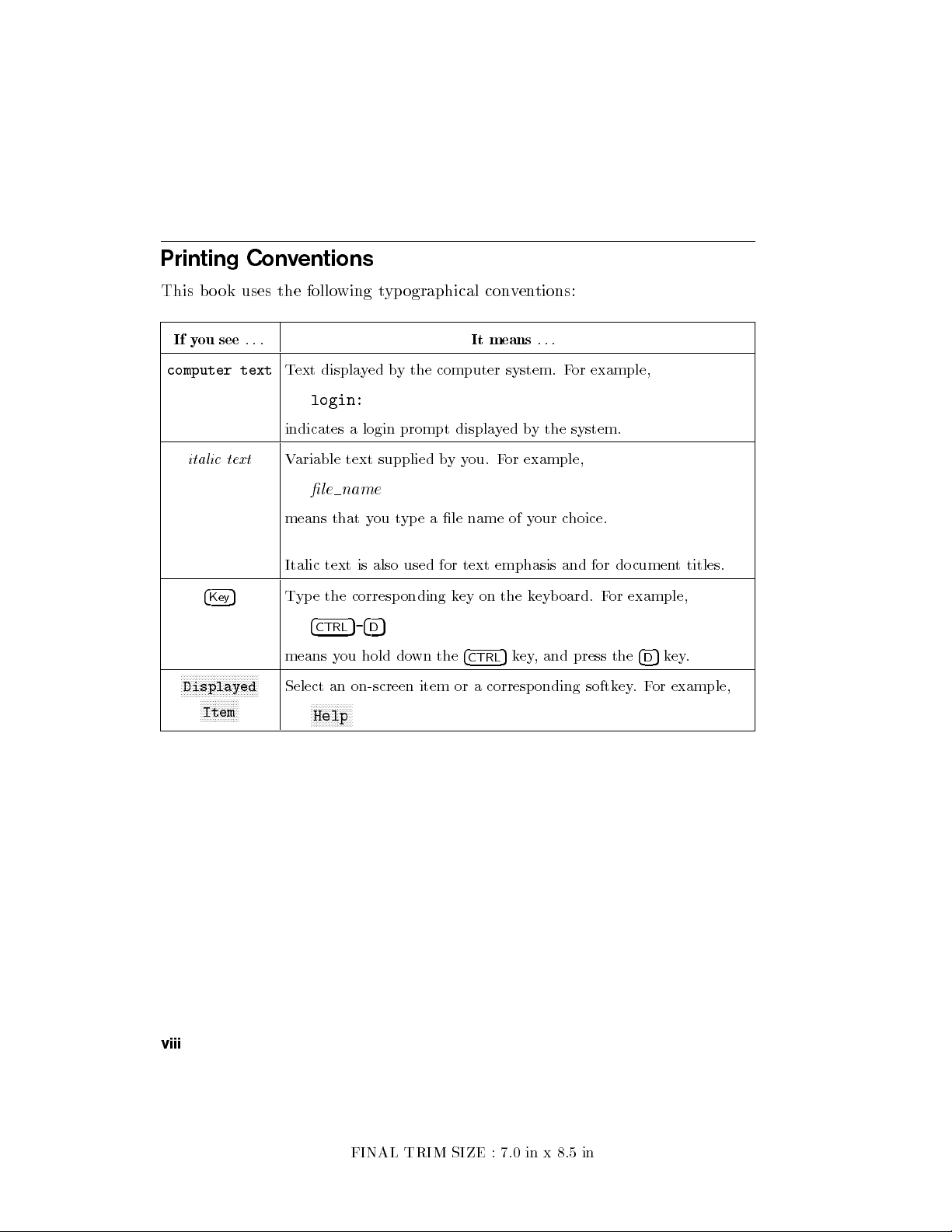
Printing Conventions
This bo ok uses the follo
If you see
computer text
...
Text displayed by the computer system. F
login:
indicates a login prompt displa
italic text
Variable text supplied byyou. For example,
le name
means that you type a le name of your choice.
Italic text is also used for text emphasis and for documen
4
Key
5
Type the corresponding key on the keyboard. For example,
4
CTRL
means you hold down the
NNNNNNNNNNNNNNNNNNNNNNNNNN
Displayed
NNNNNNNNNNNNN
Item
Select an on-screen item or a corresponding softk
NNNNNNNNNNNNNN
Help
wing typographical conventions:
It means
...
yed by the system.
5-4D5
5
4
key, and press the
CTRL
or example,
ey.For example,
t titles.
5
key.
4
D
viii
FINAL TRIM SIZE : 7.0 in x 8.5 in
Page 9
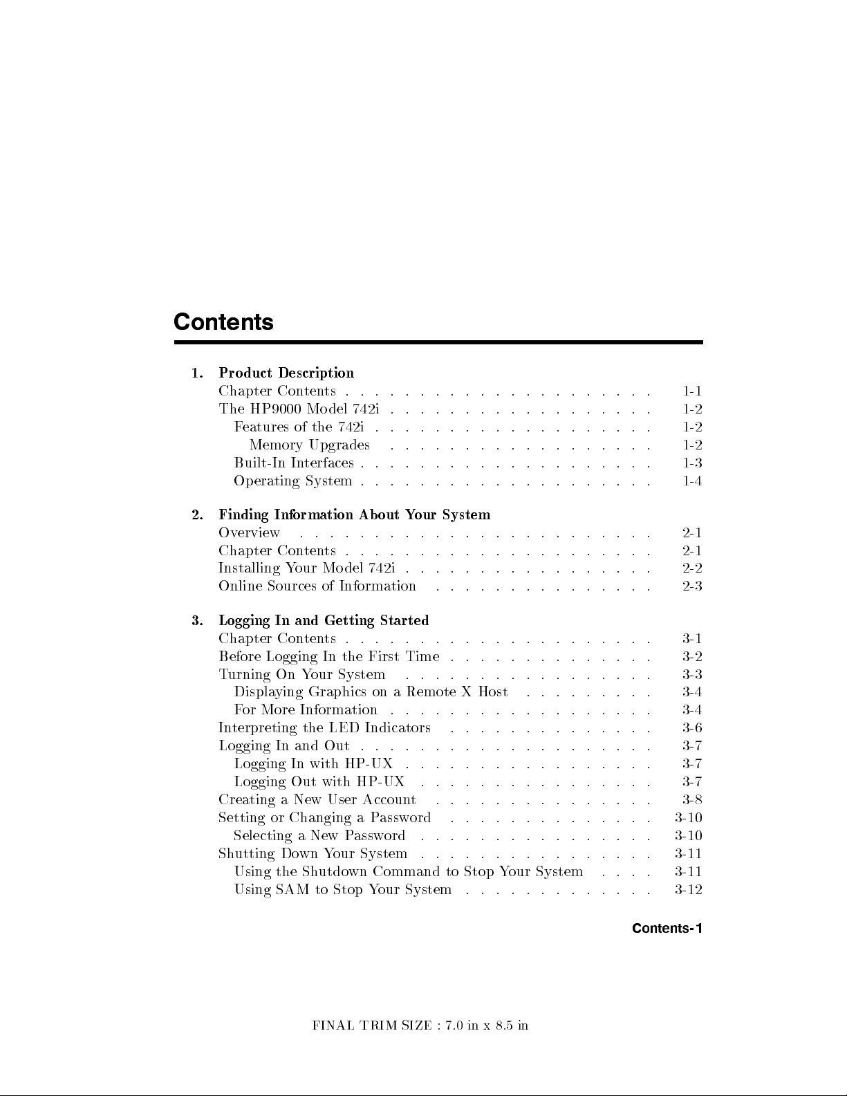
Contents
1. Product Description
Chapter Contents . . . . . . . . . . . . . . . . . . . . . 1-1
The HP9000 Model 742i
. . . . . . . . . . . . . . . . . . 1-2
Features of the 742i . . . . . . . . . . . . . . . . . . . 1-2
Memory Upgrades . . . . . . . . . . . . . . . . . . 1-2
Built-In Interfaces . . . . . . . . . . . . . . . . . . . . 1-3
Operating System . . . . . . . . . . . . . . . . . . . . 1-4
2. Finding Information About Your System
Overview . . . . . . . . . . . . . . . . . . . . . . . . 2-1
Chapter Contents . . . . . . . . . . . . . . . . . . . . . 2-1
Installing Your Model 742i . . . . . . . . . . . . . . . . . 2-2
Online Sources of Information . . . . . . . . . . . . . . . 2-3
3. Logging In and Getting Started
Chapter Contents . . . . . . . . . . . . . . . . . . . . . 3-1
Before Logging In the First Time . . . . . . . . . . . . . . 3-2
Turning On Your System . . . . . . . . . . . . . . . . . 3-3
Displaying Graphics on a Remote X Host . . . . . . . . . 3-4
For More Information . . . . . . . . . . . . . . . . . . 3-4
Interpreting the LED Indicators . . . . . . . . . . . . . . 3-6
Logging In and Out . . . . . . . . . . . . . . . . . . . . 3-7
Logging In with HP-UX . . . . . . . . . . . . . . . . . 3-7
Logging Out with HP-UX . . . . . . . . . . . . . . . . 3-7
Creating a New User Account . . . . . . . . . . . . . . . 3-8
Setting or Changing a Password . . . . . . . . . . . . . . 3-10
Selecting a New Password . . . . . . . . . . . . . . . . 3-10
Shutting Down Your System . . . . . . . . . . . . . . . . 3-11
Using the Shutdown Command to Stop Your System . . . . 3-11
Using SAM to Stop Your System . . . . . . . . . . . . . 3-12
FINAL TRIM SIZE : 7.0 in x 8.5 in
Contents-1
Page 10
Using the Command Line . . . . . . . . . . . . . . . . 3-13
4. Conguring HP-UX for Printers and Drives
Chapter Contents . . . . . . . . . . . . . . . . . . . . . 4-1
Preparing for Installation . . . . . . . . . . . . . . . . . 4-2
Conguring HP-UX for a Prin
ter . . . . . . . . . . . . . . 4-3
Testing the Printer Installation . . . . . . . . . . . . . . 4-5
Dealing With Printer Problems . . . . . . . . . . . . . 4-6
Finding the Status of Existing SCSI Bus Addresses
Conguring for a Hard Disk Drive
Software Installation of the Hard Disk Driv
. . . . . . . . . . . . . 4-8
e Upgrade . . . . 4-8
. . . . . . 4-7
Testing Your Installation . . . . . . . . . . . . . . . . . 4-10
Conguring for a Flexible Disk Drive . . . . . . . . . . . . 4-12
Testing Your Installation . . . . . . . . . . . . . . . . . 4-13
Archiving Files to a Flexible Disk . . . . . . . . . . . . . 4-14
Retrieving Files from a Flexible Disk . . . . . . . . . . . 4-14
Mounting a New Flexible Disk . . . . . . . . . . . . . . 4-15
Removing and Inserting a File-System Flexible Disk . . . . . 4-16
Conguring for a CD ROM Drive.. . . . . . . . . . . . . 4-17
Installing the CD ROM Drive with SAM . . . . . . . . . . 4-18
Testing Your Installation . . . . . . . . . . . . . . . . . 4-20
Mounting the New CD ROM Drive . . . . . . . . . . . . 4-20
Removing and Inserting a Disc . . . . . . . . . . . . . . 4-21
For More Information . . . . . . . . . . . . . . . . . . 4-22
Conguring for a DDS Tape Drive . . . . . . . . . . . . . 4-23
Conguring the Drive on HP-UX . . . . . . . . . . . . . 4-24
Testing Your Installation . . . . . . . . . . . . . . . . . 4-26
DDS Tape Drive LED Indicators . . . . . . . . . . . . . 4-27
Maximum Usage of DDS Cassettes . . . . . . . . . . . . 4-29
In Case of Diculty . . . . . . . . . . . . . . . . . . . 4-29
5. Backing Up, Restoring, and Updating Your Software
Chapter Contents . . . . . . . . . . . . . . . . . . . . . 5-1
Backing Up Your System and Software . . . . . . . . . . . 5-2
Creating a Recovery System . . . . . . . . . . . . . . . 5-2
Using mkrs to Create a Recovery System . . . . . . . . 5-3
Source Device Files . . . . . . . . . . . . . . . . . . 5-3
Root Device Files . . . . . . . . . . . . . . . . . . . 5-4
Contents-2
FINAL TRIM SIZE : 7.0 in x 8.5 in
Page 11
If You Have a Problem . . . . . . . . . . . . . . . . 5-4
Backing Up Your File Systems . . . . . . . . . . . . . . 5-4
Restoring Individual Files . . . . . . . . . . . . . . . . . 5-7
Restoring Your Operating System Using the Reco
very Tape . . 5-10
For More Information . . . . . . . . . . . . . . . . . . 5-12
6. Dealing With Problems
Chapter Contents . . . . . . . . . . . . . . . . . . . . . 6-1
Interpreting the LED Indicators . . . . . . . . . . . . . . 6-2
Managing a Boot F
Boot Program Initializes Hardw
ailure . . . . . . . . . . . . . . . . . . 6-6
are . . . . . . . . . . . . 6-6
Selecting an Alternate Operating System . . . . . . . . . . 6-6
Recovering from a System Panic . . . . . . . . . . . . . . 6-9
Procedures for Recovering from a System Panic . . . . . . . 6-11
Step 1: Note the Panic Message . . . . . . . . . . . . 6-11
Step 2: Categorize the Panic Message . . . . . . . . . . 6-11
Step 3a: Recovery from Hardware Failure . . . . . . . . 6-11
Step 3b: Recovering from a File System Problem . . . . . 6-12
Step 3c: Recovering from a LAN Communication Problem . 6-12
Step 3d: Recovering from Other Situations . . . . . . . . 6-12
Step 4: Rebooting Your System . . . . . . . . . . . . . 6-13
Step 5: Monitor the system closely . . . . . . . . . . . 6-14
For Further Information . . . . . . . . . . . . . . . . . 6-14
Dealing with Network Failures . . . . . . . . . . . . . . . 6-15
A. Installing Additional Memory
Appendix Contents . . . . . . . . . . . . . . . . . . . . A-1
RAM Replacement Contents . . . . . . . . . . . . . . . . A-2
Planning for Installation of the RAM . . . . . . . . . . . . A-3
Determining Existing Memory . . . . . . . . . . . . . . A-3
RAM Board Installation Requirements . . . . . . . . . . A-3
Installing the RAM ReplacementPairs . . . . . . . . . . . A-4
Verifying the Installation . . . . . . . . . . . . . . . . . . A-6
FINAL TRIM SIZE : 7.0 in x 8.5 in
Contents-3
Page 12
B. Using the Bo ot R
OM
Appendix Contents . . . . . . . . . . . . . . . . . . . . B-1
Boot Console User In
terface . . . . . . . . . . . . . . . . B-2
Introduction . . . . . . . . . . . . . . . . . . . . . . B-2
Special Tasks . . . . . . . . . . . . . . . . . . . . . B-2
Information Displayed . . . . . . . . . . . . . . . . . B-2
System Parameters . . . . . . . . . . . . . . . . . . B-2
Using the Boot Console User In
Entering the Bo ot Administration Mo de .
Exiting the Bo ot Administration Mode
Getting Help for the Bo ot Console User In
terface . . . . . . . . . . . B-3
. . . . . . . . . B-4
. . . . . . . . . . B-4
terface Commands . B-5
Booting the Mo del 742i . . . . . . . . . . . . . . . . . B-5
Searching for Bootable Media . . . . . . . . . . . . . . . B-7
Redisplaying the Results of a Search. . . . . . . . . . . . B-8
Displaying and Setting Paths . . . . . . . . . . . . . . . B-9
Resetting the Mo del 742i . . . . . . . . . . . . . . . . B-11
Displaying and Setting the Real-Time Clo ck . . . . . . . . B-11
Displaying and Setting the Autoselect Flag . . . . . . . . . B-12
Displaying and Setting the Secure Boot Mo de
. . . . . . . B-12
Displaying and Setting the Fastboot Mo de . . . . . . . . . B-13
Displaying the LAN Station Address . . . . . . . . . . . B-14
Using the VME Backplane Networking Parameters . . . . . B-14
Glossary
Index
Contents-4
FINAL TRIM SIZE : 7.0 in x 8.5 in
Page 13
Figures
1-1. Model 742i FrontPanel . . . . . . . . . . . . . . . . . 1-2
Tables
1-1. HP-UX Operating System and Languages for the Model 742i .
3-1. LED Diagnostic Display During Normal HP-UX Operation .
4-1. DDS Tape Drive LED State Co des . . . . . . . . . . . . 4-28
6-1. Hardware-Error LED Indications . . . . . . . . . . . . . 6-2
6-2. Operating-System Error LED Indications . . . . . . . . . 6-4
6-3. Problems with the Network . . . . . . . . . . . . . . . 6-15
B-1. System Paths . . . . . . . . . . . . . . . . . . . . . . B-9
B-2. Mnemonic Style Notation . . . . . . . . . . . . . . . . B-9
1-4
. 3-6
FINAL TRIM SIZE : 7.0 in x 8.5 in
Contents-5
Page 14

FINAL TRIM SIZE : 7.0 in x 8.5 in
Page 15
Product Description
Chapter Contents
The HP 9000 Mo del 742i is an exceptionally exible, high-performance
Precision Architecture system based on the Hewlett-Packard PA RISC 7100
technology. Some features are outlined in the following sections.
1
1
FINAL TRIM SIZE : 7.0 in x 8.5 in
Product Description 1-1
Page 16
1
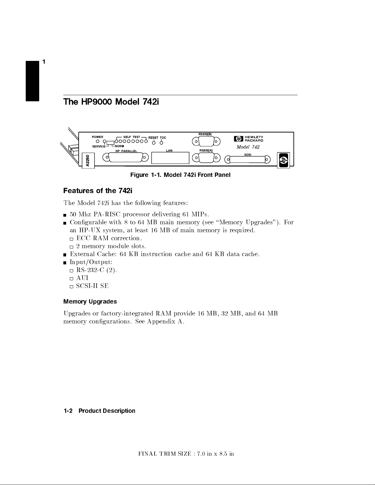
The HP9000 Model 742i
Figure 1-1. Model 742i Front P
Features of the 742i
The Mo del 742i has the following features:
50 Mhz PA-RISC processor delivering 61 MIPs.
Congurable with 8 to 64 MB main memory (see \Memory Upgrades"). F
an HP-UX system, at least 16 MB of main memory is required.
ECC RAM correction.
2 memory module slots.
External Cache: 64 KB instruction cache and 64 KB data cache.
Input/Output:
RS-232-C (2).
AUI
SCSI-II SE
Memory Upgrades
Upgrades or factory-integrated RAM provide 16 MB, 32 MB, and 64 MB
memory congurations. See Appendix A.
anel
or
1-2 Product Description
FINAL TRIM SIZE : 7.0 in x 8.5 in
Page 17
Built-In Interfaces
1
For graphics, printing, and LAN communications, the Mo del 742i pro
following I/O interfaces:
HP-Parallel Interface.
LAN AUI (15-pin D-subminiature; requires MAU for connection to LAN).
2 Asynchronous RS-232 Interfaces: 9-pin male DTE (PC standard).
SCSI-II Interface: 50-pin high density; single-ended 8-bit, up to 5 MB/sec.
synchronous.
The I/O for the Model 742i is on the fron
Physical Dimensions and Power Requirements
Height: 40.6 mm. (2 VMEbus slots).
Width: 233.3 mm. (9.2 in.)
Depth: 160 mm. (6.3 in.)
Weight: .91 kg. (2.0 lb.)
Power:
35 watts @ +5 vdc.
0.12 watts @ +12 vdc.
0.12 watts @ -12 vdc.
t panel, shown on the opposite page.
vide the
FINAL TRIM SIZE : 7.0 in x 8.5 in
Product Description 1-3
Page 18
1
Operating System
HP-UX 9.01 for the Mo del 742i the HP VUE in
System.
Table 1-1 lists the HP-UX op erating system features and languages for the
Model 742i.
Table 1-1.
HP-UX Operating System and Languages for the Model 742i
Operating system: HP-UX 9.01 or later. HP-UX complies with X
POSIX specications.
Languages: HP-PA Assembly, ANSI/C,
FORTRAN/9000.
User interface: Terminal Interface via RS232 only. By using LAN, the X
Window System 11R5 (OSF/Motif 1.2)and HP VUE 3.0
can be used on a suitable X T
Network Features: IEEE 802.3/Ethernet Local Area Network:
S.25.
SNA.
RJE.
TCP-IP.
HP Diskless.
terface, and the X Windo
Open, and
C++
,Pascal, HP-UX
erminal display).
w
1-4 Product Description
FINAL TRIM SIZE : 7.0 in x 8.5 in
Page 19
Finding Information About Your System
Overview
Your Mo del 742i uses the standard HP-UX 9.01 operating system, a highly
versatile system for multitasking, running your application programs, and
performing a variety of other tasks.
Chapter Contents
Installing Your Model 742i.
Online Sources of Information.
2
2
Finding Information About Your System 2-1
FINAL TRIM SIZE : 7.0 in x 8.5 in
Page 20
2
Installing Your Model 742i
If you have not installed your hardware or started your system, refer to the
Instal lation Guide
for your system before going further.
Basic Information
After you have read the
Instal lation Guide
for your system, you maywantto
see the following sources for further information:
For a quick reference to commonly-used HP-UX commands, see the
Appendix in
Using HP-UX
.
At some point, you maywanttointeract with the Mo del 742i via the LAN
using HP VUE with an X Window System display. HP VUE is the default
interface for HP-UX. As a simpler window alternative, you can also use the X
Window System. Both are included in HP-UX. For further information, see
the manual
Guide
Using the X Window System,Using HP-UX
.
,or
HP VUE User's
The following manuals will also be useful:
If you have not yet installed your HP-UX system, see
Updating HP-UX 9.0
For administration information, see
For troublesho oting HP-UX, see
, whichcovers HP-UX 9.01.
System Administration Tasks
Solving HP-UX Problems
Instal ling and
.
, and Chapter 6
in this manual.
For VME conguration information, see
VME Conguration Guide for
HP-UX
2-2 Finding Information About Your System
FINAL TRIM SIZE : 7.0 in x 8.5 in
Page 21
Online Sources of Information
2
HP-UX is designed so that y
leaving your system. Some of these information sources are a
ou can access many sources of information without
vailable through a
shell command line.
Man Pages: The information on HP-UX whic
is also on line and accessible b
y clicking on the Toolb ox button at the righ
of your FrontPanel, or byentering on a command line
command
is the name of the HP-UX command y
on. If you're not sure of the command name y
where
keyword
is a likely topic w
ord to search on. This will result in a
h is found in
HP-UX Reference
man
command
ou want to get information
ou can enter
man -k
keyword
t
, where
display listing commands having the keyword in their description.
There are also a variety of les on your HP-UX system which contain
version-specic information which will be useful in administering and
conguring cards and devices for your version of HP-UX. Among these are the
following:
Release Notes: This is the online version of the Release Notes which came
with your system. It contains all the late information, undocumented
changes and bug xes for your release of HP-UX. Release Notes is found in
the
/etc/newconfig
e.g.,
90RelNotes
Terminfo: The directory
containing information ab out terminal congurations, indexed b
directory, and may be named by its release number,
, for HP-UX 9.0.
/usr/lib/terminfo
contains subdirectories
y the
rst character of the terminal name. For example, to nd conguration
information ab out the hp98546, you can lo ok in
/usr/lib/terminfo/h
for a
listing of information les for all the terminal names beginning with \h".
,
These lenames also constitute all the acceptable arguments for setting the
TERM variable, in case you are using a non-default terminal conguration.
Finding Information About Your System 2-3
FINAL TRIM SIZE : 7.0 in x 8.5 in
Page 22
2
Newcong: The directory
versions of HP-UX pro duct conguration les, as w
mayhave been customized (lo calized) on y
directory will vary depending on which products y
system. In most cases, old v
the le system, are not o
le in
/etc/newconfig
/etc/newconfig
ersions of these les, in their regular lo cations in
verwritten by the update process. See the README
for information on the contents of this directory
contains information and new
ell as shell scripts whic
our system. The contents of this
ou have loaded on your
.
h
2-4 Finding Information About Your System
FINAL TRIM SIZE : 7.0 in x 8.5 in
Page 23
3
Logging In and Getting Started
Chapter Contents
Before Logging In the First Time.
Turning On Your System.
Interpreting the LED Indicators.
Logging In and Out.
Creating a New User Account.
Setting or Changing a Password.
Getting Help.
Shutting Down Your System.
3
Logging In and Getting Started 3-1
FINAL TRIM SIZE : 7.0 in x 8.5 in
Page 24
Before Logging In the First Time
If your Mo del 742i system does not ha
system disk, and you want it to be a cluster clien
manual
3
clusters and cno des.
Managing Clusters of HP-UX Computers
This chapter reviews some initial procedures and pro
both HP VUE sessions and HP-UX. F
HP VUE after login, see the
HP VUE User's Guide
When you turn on your Mo del 742i to complete the installation pro cess, y
ve a hard disk attached, or if it has a le
t node (cnode), refer to the
for instructions on setting up
vides information on using
or more detailed information ab out using
.
ou
will be asked for the following information. If you do not have this information
5
readily available, simply press
4
Return
after the questions, and you can supply
this information later:
The time zone where your system is lo cated.
The host name for your system; any alphanumeric, single-word name with
eight or fewer characters.
The network address number, also called an IP number, for your system.
This consists of four address elds separated b
255.32.3.10
.You may need to consult with your system administrator for
y perio ds: for example,
this information. Or, if your host name and IP number have already been
assigned, you can nd out the host name, after b oot, b
yentering
uname -a
.
If you knowyour host name, you can nd out your IP number byentering
nslookup
host name
, at the system prompt.
If you can't supply this information at boot time, y
ou can congure it into the
system later, after logging in, byentering the command
You can then enter the information at the prompts.
3-2 Logging In and Getting Started
FINAL TRIM SIZE : 7.0 in x 8.5 in
set_parms
,as
root
.
Page 25
Turning On Your System
With all p eripheral devices turned o, do the follo wing:
1. Turn on the p o
unit will show that it is turned on, ev
wer to your display. The power indicator LED on the displa
en if the screen remains dark. Mak
sure of the following:
a. The appropriate LAN connection has b een made to the Model 742i.
b. Normally,you will use a c
port on the Mo del 742i. If y
haracter terminal connected to the RS232A
ou use a remote graphical displa
y host
connected via LAN, make sure the remote system is congured to host
the Model 742i. See \Displaying Graphics on a Remote X Host", in this
chapter, for the sp ecics of setting this up.
2. Check SCSI connections and turn on the po
3. Turn your Mo del 742i system on. The LEDs on the fron
wer to any peripheral devices.
t panel will light,
showing that the power ison.
4. You should see a sequence of boot messages. Allow the boot to con
5. During the boot pro cess, messages will prompt y
ou for the host name, IP
tinue.
number, and time zone. If you have this information, enter it as requested.
Otherwise, press
set_parms
4
Return
4
5
.You can also enter this information later bytyping
Return
5
after login.
6. You will be asked if you want to set a ro ot password at this time. If you
choose to do this, see \Selecting a New P
assword", in this chapter, for
password requirements.
y
e
3
The system will nish the bo ot sequence, and y
login:
" prompt.
Logging In and Getting Started 3-3
FINAL TRIM SIZE : 7.0 in x 8.5 in
ou will see the \
Console
Page 26
Displaying Graphics on a Remote X Host
With the Model 742i, y
cannot directly display them. However, you can use a remote computer whic
has graphical capabilit y to displa
interact with it. This is done b
3
the Model 742i.
DISPLAY
which a system sends bitmapped output for clien
For example, if the Model 742i is called
xhost system
, and the program running on the Mo del 742i is called
enter the following on y
ou can run HP VUE or the X Windo
w System, but you
y the system running on the Mo del 742i and
y setting the
DISPLAY
environmentvariable on
sets the host, displaynumber, and screen n
ts.
server
system
,your remote system is
our remote X host system to get it to displa
h
umber to
xwijit
,
y the Mo del
742i bits:
xhost +
server system This enables the Model 742i to recognize the
remote X host.
rlogin
DISPLAY=
server system Log in on the Model 742i.
xhost system
:0.0
On the Model 742i, set the
DISPLAY
variable so
that it wil l display on your remote X system.
export DISPLAY
xwijit
Export the variable
Run the program on the Model 742i
For More Information
For detailed information on running HP VUE in a net
the
HP VUE User's Guide
.
worked environment, see
3-4 Logging In and Getting Started
FINAL TRIM SIZE : 7.0 in x 8.5 in
Page 27
Caution
If your system has its o
operating system, do not turn o po
rst shutting down the operating system softw
the pro cedure in this c
Turning o the po
wn disk and you are running a lo cal
wer to your system without
are according to
hapter, \Shutting Down Your System".
wer for your stand-alone system without rst
doing the shutdown procedure may result in damage to data on
your disk. Always execute the shut-down process to completion
rst.
If you are running your system as a node in a cluster (without
a le system disk) you can, in an
y case, shut down your system
by turning o the power after you have properly closed les
and terminated processes. If you have a mounted le system
disk, you must become
root
and perform the procedure
in \Shutting Down Your System", or haveyour system
administrator do so. You can run
by being listed in the le
Administration Tasks
/etc/shutdown.allow
for details.
shutdown
without
. See
being
System
root
3
Logging In and Getting Started 3-5
FINAL TRIM SIZE : 7.0 in x 8.5 in
Page 28
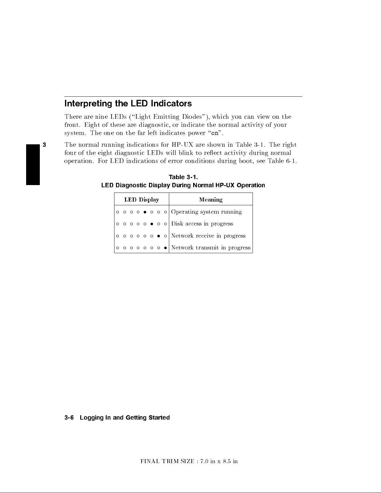
Interpreting the LED Indicators
There are nine LEDs (\Ligh
front. Eight of these are diagnostic, or indicate the normal activit
system. The one on the far left indicates po
3
The normal running indications for HP-UX are sho
four of the eight diagnostic LEDs will blink to reect activit
operation. For LED indications of error conditions during boot, see T
LED Diagnostic Display During Normal HP-UX Operation
LED Display Meaning
t Emitting Dio des"), whic
wer \on".
wn in Table 3-1. The righ
Table 3-1.
Operating system running
Disk access in progress
Network receive in progress
Network transmit in progress
hyou can view on the
yofyour
t
y during normal
able 6-1.
3-6 Logging In and Getting Started
FINAL TRIM SIZE : 7.0 in x 8.5 in
Page 29
Logging In and Out
Once HP-UX is running on y
logging in is one of the w
using your system. This is esp ecially important if y
our system, you must log in. The process of
ays that HP-UX prevents unauthorized p ersons from
our system is attached to a
network.
Logging In with HP-UX
If you are not using HP VUE, then a command-line login prompt appears after
boot:
login:
1. Type your login name (or
2. Press
If you
4
Return
haven't
5
.
yet set a password, you will get a a system prompt (\#" for
root
).
root, or$for user), and you can b egin using the system.
3. Otherwise, type your password when the system gives the following prompt:
Password:
4.
Press
4
5
. The system prompt (\#"or\$") appears and you can use the
Return
system.
3
Logging Out with HP-UX
If you are not using HP VUE, you can use the
lock
command to temporarily
leaveyour system (while leaving processes running). If you want to log out of
your currentwork session entirely, use the following command:
exit
Logging In and Getting Started 3-7
FINAL TRIM SIZE : 7.0 in x 8.5 in
Page 30
Creating a New User Account
If you have access to a system administrator, that person ma
up a user account for you. Otherwise, you will need to do the follo
up a user account so that you can interact with the system as non-
3
not incur the risk of acciden
You usually work in your home directory or \accoun
tally damaging data.
t", and most of y
yhave already set
wing to set
root
and
our
default les are kept there. As \owner" of this directory and its subdirectories,
you also have control over access to the les in the accoun
t.
Using SAM
To create a user account, you will need to use \SAM", the System
Administration Manager.
Caution
In order to use SAM, you must be logged in as
by the command prompt \#"). The
root
root
(indicated
account is a separate
login account providing unlimited p ermissions on your system.
This means that you need to take actions more carefully when
you are
root
. The
root
account is only used to do system
administration tasks, and, for security reasons, it should use a
password which is dierent from your everyday user password.
Using HP-UX
and
System Administration Tasks
giveyou more
details on using SAM.
You can navigate around a SAM screen on a character terminal using the
arrow keys and
selection is illuminated, press
1. Type
2.
At the opening menu, choose
NNNNNNNNNNNNNNNNNNNNNNNNNNNNNNNNNNNNNNNNNNNNNNNNNNNNNNNN
Users and Groups->
3.
At the next screen, choose
4
5
to illuminate the selection you want to activate. When the
Tab
usr/bin/sam
,as
root
illuminated.
4
5
Return
to activate, or \choose" it.
, followed by
4
Return
NNNNNNNNNNNNNNNNNNNNNNNNNNNNNNNNNNNNNNNNNNNNNNNNNNNNNNNN
Users and Groups->
NNNNNNNNNNNNNNNNN
Users
.You will see a screen displaying a list of
5
.
pressing
4
Return
5
logins and real names.
3-8 Logging In and Getting Started
FINAL TRIM SIZE : 7.0 in x 8.5 in
with
Page 31

4.
Go to the
menu bar). Select
NNNNNNNNNNNNNNNNNNNNNNNNNNNNNNNNNNNNNNNNNNNNNNNNNNNNNNNN
form
Add a User Account
NNNNNNNNNNNNNNNNNNNNNNN
Actions
menu (use the appropriate function k
NNNNNNNNNNN
Add
from the
NNNNNNNNNNNNNNNNNNNNNNN
Actions
pull-down menu. You will see a
.
ey to get to the
5. Fill in your login name, c
dierent from the defaults giv
Note
At this p oin
hoice of start-up program and en
en), and the optional information.
tyou can select X Windo
ws as your login default
vironment (if
environment, if you so desire.
NNNNNNNN
6. Choose
OK
when you are nished.
7. You will be asked to select a password. (See \Selecting a New Password"
for password requirements. If you wish, you can select a temp orary
password and reset it later). Type the password and choose
press
4
5
). Re-enter the password, as requested, and choose
Return
NNNNNNNN
OK
(or
NNNNNNNN
OK
. The
re-entered password must match the rst.
8.
Choose
9.
When the \Task Completed" message appears, choose
10.
Press the
11.
Type
NNNNNNNN
OK
NNNNNNNNNNNNNNNNNNNNNNNNNN
Exit SAM
exit
.
4
Return
function key.
5
to leave SAM.
NNNNNNNN
OK
.
3
Logging In and Getting Started 3-9
FINAL TRIM SIZE : 7.0 in x 8.5 in
Page 32

Setting or Changing a P
assword
From a command line shell prompt, y
directly to set or c
hange a password. (You do not havetobe
ou can use the
passwd
command
root
). Enter the
following:
3
passwd
You will be prompted for y
4
Return
5
our old password. Then you will be prompted to
enter and re-enter your new password. The re-entered password must match
the rst entry.
See the later section in this chapter, \Selecting a New Password", if you
need help with selecting passwords. Use the same procedure to change an
old password as to add a new password. If you already have one, you will be
prompted appropriately for the old password.
Selecting a New Password
If you have already b ooted and used your system, you should already have set
dierent passwords for your user account and for
root
.
However, you will also wanttochange your password from time to time as a
matter of goo d security practice. The following gives the general requirements
of setting passwords.
A password must meet four criteria to b e valid:
Contain at least six characters.
At least twocharacters must be alphab etic.
At least one character must be a number (0-9) or a sp ecial character (/, ?, !,
or other punctuation mark).
Dier from your previous password by at least three characters.
Your password is case-sensitive, so the password
password
?secret
.Your password can also be as long as you want, but only
?Secret
is dierent from the
the rst eightcharacters are checked.
If you are adding many users to your system, see
System Administration Tasks
for the details of controlling access to your system.
If you have not yet set your password, you can do so using SAM or a shell
command line.
3-10 Logging In and Getting Started
FINAL TRIM SIZE : 7.0 in x 8.5 in
Page 33

Shutting Down Your System
If you need to cycle p o
to execute the
shutdown
wer on a system using a local disk, y
ou will have
command rst. You can do this either from the
command line or within SAM.
Using the Shutdown Command to Stop Y
Caution
If your Mo del 742i uses a lo cal system disk, do not turn o
power to your system without rst sh
system software according to the follo
our System
utting down the operating
wing pro cedure. Turning
o the power for your system without rst doing the shutdown
procedure may result in damage to data on your disk. Always
execute the shut-down process to completion rst.
1. As
root
,enter the following command:
shutdown -h
This will giveyou and any other users on your system a one-minute \grace
period" to save les and terminate pro cesses before the system goes do
the halted state.
2. You will see a message:
Waiting a grace period of 60 seconds for users to logout.
Do not turn
off the power or press reset during this time.
3
wn to
(You can sp ecify this message and you can determine the \grace period"
that
shutdown
allows. See
shutdown
(1M)) and
System Administration Tasks
for using various options.
3. At the end of the perio d, y
ou will see another warning and the following
request for conrmation:
Do you want to continue? ...
4. Respond withy.You will see another message conrming shutdown.
Finally,you will see the following message:
Halted, you may now cycle power.
Logging In and Getting Started 3-11
FINAL TRIM SIZE : 7.0 in x 8.5 in
Page 34

5. At this time the system no longer responds to k
turn o the po
wer. Turning the system back on again will initiate the boot
process.
eyboard input and y
ou may
If you wanttoshutdown and reboot automatically t
ype the following
command:
3
shutdown -r.
If you wanttoshutdown immediately with no grace perio d, t
ype the following:
shutdown -h 0
Using SAM to Stop Your System
If you happen to b e using SAM, you might also want to use it to shut down
your system.
Caution
Do not turn o power to your system without rst shutting
down the operating system software according to the following
procedure. Turning o the power for your system without rst
doing the shutdown procedure may result in damage to data on
your disk. Always execute the shutdown process to completion
rst.
You can log in as
1. As
root
2.
Choose
NNNNNNNNNNNNNNNNNNNNNNNNNNNNNNNNNNNNNNNNN
Routine Tasks
root
type
/usr/bin/sam
and shut down your system, using SAM.
.
from the opening menu.
3-12 Logging In and Getting Started
FINAL TRIM SIZE : 7.0 in x 8.5 in
Page 35

3.
Choose
NNNNNNNNNNNNNNNNNNNNNNNNNNNNNNNNNNNNNNNNNNNNNNN
System Shutdown
.
4. You will be given a choice of the following:
NNNNNNNNNNNNNNNNNNNNNNNNNNNNNNNNNNNNNNNNNNNNNNN
a.
Halt the System
. All currently executing pro cesses except those
essential to the system are terminated. Then the system is halted.
NNNNNNNNNNNNNNNNNNNNNNNNNNNNNNNNNNNNNNNNNNNNNNNNNNNNNNNNNNNNNNNNNNNNNNNNNNNNNNNNNNN
b.
Reboot (Restart) the System
. The system is sh
ut down and reb ooted
automatically.
NNNNNNNNNNNNNNNNNNNNNNNNNNNNNNNNNNNNNNNNNNNNNNNNNNNNNNNNNNNNNNNNNNNNNNN
c.
Go to Single User State
administrative purposes such as backup or le system consistency c
. The system is put in single-user mo de for
hecks.
5. Exit SAM using the appropriate function key.
Using the Command Line
For guidance on entering commands and using the HP-UX le system, to ols,
and networking commands, see the manual,
work with shell programming, see the manual
Using HP-UX
.For more advanced
Shells: User's Guide
.
3
Logging In and Getting Started 3-13
FINAL TRIM SIZE : 7.0 in x 8.5 in
Page 36

FINAL TRIM SIZE : 7.0 in x 8.5 in
Page 37

4
Configuring HP-UX for Printers and Driv
Chapter Contents
Preparing for Installation.
Conguring HP-UX for a Printer.
Finding the Status of Existing SCSI Bus Addresses.
Conguring for a Hard Disk Drive.
Conguring for a Flexible Disk Drive.
Conguring for a CD ROM Drive.
Conguring for a DDS Tape Drive.
es
4
Configuring HP-UX for Printers and Drives 4-1
FINAL TRIM SIZE : 7.0 in x 8.5 in
Page 38

Preparing for Installation
If you have external devices attached to y
(or congure) them on HP-UX. Y
ou may also have to do some conguration
our system, you will have to install
for appropriate data interchange with a new printer. This chapter gives you
general guidance for these tasks.
In general:
For a list of devices whic
See the
4
on hardware installation. You can also get installation information from
Installation Guide
Installing Peripherals
h are supp orted by the Model 742i, see Chapter 1.
for the device you are installing for information
.
Ensure that each new device you install which communicates through the
SCSI proto col has a
unique bus address
.You can use
/etc/ioscan
(see
\Finding the Status of Existing SCSI Bus Addresses") to determine this, or
you can use SAM (System Administration Manager). The factory-set SCSI
addresses for the devices in this chapter are as follows:
Hard Disk Drive:
Flexible Disk Drive:
CD ROM Drive:
DDS Drive:
6
0
2
3
This chapter shows you how to use essential SAM (System Administration
Manager) procedures. SAM will determine the status of an
connected devices and will perform softw
are installation tasks for you.
yofyour
If you don't want to use SAM, or it is not on y
our system, you can also
HP-UX commands directly to accomplish the same tasks. For information on
using manual system administration procedures, see
Tasks
.
System Administration
4-2 Configuring HP-UX for Printers and Drives
FINAL TRIM SIZE : 7.0 in x 8.5 in
Page 39

Configuring HP-UX for a Printer
You will need to supply certain items of information needed to iden
printer you are installing. It will help to ha
to during the softw
are installation process:
ve this information available to refer
tify the
Printer Interface:
Parallel:
Serial (RS232) Port 1:
Serial (RS232) Port 2:
Printer Name (a name the system uses to identify the printer. It can be any
name.):
Printer Model Number (lo cated on a label on the bac
k of the printer):
Procedure:
To install your printer:
1. Log in as
root
.
4
2. Run SAM bytyping:
/usr/bin/sam
5
To get help in SAM, pressing the
key gives you context-sensitive
4
f1
information for the ob ject at the location of the cursor.
Use the arrow keys and
screen. Press
3.
At the SAM opening screen, choose
4.
Choose
4
Return
NNNNNNNNNNNNNNNNNNNNNNNNNNNNNNNNNNNNNNNNNNNNNNNNNNNNN
Printers/Plotters
4
5
to move the highlighted areas around the
Tab
5
to \choose" an item when illuminated (suchas
NNNNNNNNNNNNNNNNNNNNNNNNNNNNNNNNNNNNNNNNNNNNNNNNNNNNNNNNNNNNNNNNN
Printers and Plotters
from the next screen.
Configuring HP-UX for Printers and Drives 4-3
FINAL TRIM SIZE : 7.0 in x 8.5 in
NNNNNNNN
OK
).
.
Page 40

If your system doesn't haveany printers connected, you will see a message.
Make sure you have a printer connected. Choose
5.
From the
choose
NNNNNNNNNNNNNNNNNNNNNNN
Actions
NNNNNNNNNNNNNNNNNNNNNNNNNNNNNNNNNNNNNNNNNNNNNNNNNNNNNNNNNNNNNNNNNNNNNNNNNNNNN
menu (on the men
Add Local Printer/Plotter
u bar at the top of the screen),
NNNNNNNN
OK
or press
4
Return
5
.
6. Choose an appropriate selection on the sub-men
u giving options for
Parallel, Serial, HP-IB, etc.
7. A screen will giv
8.
If you chose
4
one serial interface could be listed. The serial in
eyou information on available parallel or serial interfaces.
NNNNNNNNNNNNNNNNNNNNNNNNNNNNNNNNNNNNNNNNNNNNNNNNNNNNNNNNNNNNNNNNNNNNNNNNNNNNNNNNNNNNNNNNNNNNNNNNNNNNNNNNNN
Add Serial (RS-232) Printer/Plotter
, more than
terfaces are listed in
ascending order. The lowest-numbered serial interface corresponds to the
lowest-numbered serial connector on your system. Choose the one to which
you have connected your printer.
9.
Choose
NNNNNNNN
OK
NNNNNNNNNNNNNNNNNNNNNNNNNNNNNNNNNNNNNNNNNNNNNNNNNNNNNNNNNNNNNNNNNNNNNNNNNNNNN
A display opens for
10.
Choose the box lab eled
Add Local Printer/Plotter
NNNNNNNNNNNNNNNNNNNNNNNNNNNNNNNNNNNNNN
Printer Name
and enter your
.
printername
for the
new printer (entered in the blank earlier).
11.
Choose
12. Scroll down the next screen, using the arrow k
NNNNNNNNNNNNNNNNNNNNNNNNNNNNNNNNNNNNNNNNNNNNNNNNNNNNNNNNNNNNNNNNNNNNNNN
Printer/Model Interface
eys, to nd the Model Name
of your printer.
5
13. Choose the Mo del Name (press
14.
Choose
15.
In the
choose the b ox labeled
16.
Choose
NNNNNNNN
OK
.
NNNNNNNNNNNNNNNNNNNNNNNNNNNNNNNNNNNNNNNNNNNNNNNNNNNNNNNNNNNNNNNNNNNNNNNNNNNNN
Add Local Printer/Plotter
NNNNNNNNNNNNNNNNNNNNNNNNNNNNNNNNNNNNNNNNNNNNNNNNNNNNNNNNNNNNNNNNNNNNNNNNNNNNNNNNNNNNNNNNNNNNNNNNNNNNNNNNNNNNN
Make this the system default printer
NNNNNNNN
OK
.
4
Return
when illuminated).
display which reappears, select and
.
17. If the print spo oler was not previously running, a screen will appear with
the question:
NNNNNNNNNNN
Yes
or press
NNNNNNNNNNNNNNNNNNNNNNNNNNNNNNNNNNNNNNNNNNNNNNNNNNNNNNNNNNNNNNNNNNNNNNNNNNNNNNNNNNNNNNNNNNNNNNNNNNNNNNNNNNNNNNNNNNNNNNNNNNNNNNN
Do you want to start the print spooler now?
4
5
.
Return
NNN
. Choose
4-4 Configuring HP-UX for Printers and Drives
FINAL TRIM SIZE : 7.0 in x 8.5 in
Page 41

18. You will see a conrmation screen asking if y
connected to your system, and online. Chec
5
is ready, and press
19.
You will see the message
20.
Exit the task and press the
4
.
Return
NNNNNNNNNNNNNNNNNNNNNNNNNNNNNNNNNNNNNNNNNNNN
Task completed
NNNNNNNNNNNNNNNNNNNNNNNNNN
Exit SAM
. Press
function key.
our printer is turned on,
kyour printer to ensure that it
5
Return
.
4
21.
Type
Refer to
exit
System Administration Tasks
4
Return
5
to exit
root
and return to
user
status.
, for additional SAM information.
Testing the Printer Installation
If you made your printer the default system printer, type the following
commands to test it:
cd
4
5
Return
lp .profile
(If your printer (called
4
Return
5
printername
) isn't the default system printer, enter the
following command to test it:)
lp -d
printername
The le named
.profile
.profile
4
Return
5
should print out on your new printer.
4
Configuring HP-UX for Printers and Drives 4-5
FINAL TRIM SIZE : 7.0 in x 8.5 in
Page 42

Dealing With Printer Problems
If you experience problems in prin
The power cord for the prin
The printer is turned on.
The printer selection switches are set for online.
Paper is loaded in
The correct interface has been set up.
4
The printer cable is connected to the correct in
The cable is connected to the correct port on y
to the printer (and it isn't jammed).
ting, check the following:
ter is plugged in.
terface port on y
our system.
our printer.
4-6 Configuring HP-UX for Printers and Drives
FINAL TRIM SIZE : 7.0 in x 8.5 in
Page 43

Finding the Status of Existing SCSI Bus Addresses
Before you attach a new SCSI driv
your device is currently unused, you can use SAM, or y
tool to help determine whic
h devices are currently connected. To determine the
currently connected SCSI bus IDs, en
e, to ensure that the SCSI bus address of
ou can use the
ioscan
ter the following command line:
/etc/ioscan -fb
The result will be a displa
y of information, such as the following:
Class H/W Path Driver H/W Status S/W Status Description
=========================================================================
...
disk 2.0.1.2.0 scsi ok(0x5800101) ok TOSHIBA CD-ROM
tape_drive 2.0.1.3.0 scsitape ok(0x1800202) ok HP HP35450A
disk 2.0.1.6.0 scsi ok(0x101) ok MICROP 1528
...
For example, the SCSI bus address for the \MICR
fourth column of its hardware address as \6"(
OP" disk device is in the
2.0.1.6.0
). If you were
installing another disk, for le system use, it would b est be accessed at the
adjacent SCSI bus address in the \scanning" order, \
5
". SAM would help you
determine where to put it when you did the installation.
4
Configuring HP-UX for Printers and Drives 4-7
FINAL TRIM SIZE : 7.0 in x 8.5 in
Page 44

Configuring for a Hard Disk Driv
e
Hard disk drives can be attached for accommodating HP-UX, local le systems,
and swap space on your Mo del 742i system.
Software Installation of the Hard Disk Driv
After all connections have been made (see the
device), you'll need to ensure that y
our operating system is prepared to
exchange data with the device. This section pro
conguring HP-UX to communicate with hard disk driv
4
the disks for mass storage and/or swap space. Note that your HP disk is
e Upgrade
Instal lation Guide
for this
vides instructions for manually
es, in order to use
pre-formatted.
The factory-set SCSI bus address for the disk drive:
SCSI bus address:
This SCSI address assumes usage of the disk as
6
root
. Although the
conguration jumpers in the back of the drive are factory-installed and should
not require reconguring, it is possible that the SCSI bus address jumpers
for the disk may be shipped with dierent settings. Therefore, please see the
Instal lation Guide
for the drive for the procedure for resetting jump ers, should
it be necessary.
The following list outlines the software procedures you'll nd in this section for
installing the hard disk drive as a le system disk:
Verify that you haveanunused device le with the correct select co de and
bus address for your device. (Use SAM or the script in \Finding the Status
of Existing SCSI Bus Addresses").
Use SAM to:
Install a disk on HP-UX.
Build a le system on the disk (done automatically by SAM).
Mount the disk so that you can access it as a le system.
4-8 Configuring HP-UX for Printers and Drives
FINAL TRIM SIZE : 7.0 in x 8.5 in
Page 45

Note
SAM does not support the follo
wing:
Changing the hardware address of a disk driv
e containing
the root le system.
Changing the hardware address of a disk array
.
Changing the hardware address of a disk that is part of
software disk striping.
After all appropriate connections ha
ve been made (see the
Instal lation Guide
for this device), you'll need to ensure that your operating system is prepared
to exchange data with the device. This section pro
vides instructions for doing
this.
1. Run SAM bytyping:
/usr/bin/sam
Pressing the
4f15
key gives you context-sensitive information for the ob ject
at the location of the cursor.
NNNNNNNNNNNNNNNNNNNNNNNNNNNNNNNNNNNNNNNNNNNNNNNNNNNNNNNNNNNNNNNNNNNN
2. Choose
4
Return
3.
Choose
Disks and File Systems
5
).
(highlight the selection and press
NNNNNNNNNNNNNNNNNNNNNNNNNNNNNNNNNNNNNNNNNNNNNNNNNNNNNNNNNNNNNNNNNNNNNNNNNNNNNNNNNNNNNNNNNNNN
CD-ROM, Floppy, and Hard Disks
.
4. Choose the line identifying the type of new disk you have connected. In the
\Use" column, it will be designated as \unused".
4
5. In the next screen, choose the line identifying the model of the new disk.
If the device you have connected does not app ear on the list:
a. Checkyour connections, and make sure that the device is turnedon.
b.
Choose the button
NNNNNNNNNNNNNNNNNNNNNNNNNNNNNNNNNNNNNNNNNNNN
Device Missing
, and you will be given the
following options:
i. Have SAM rescan the system for the device. If you have connected
the device
choose
NNNNNNNN
No
after
starting SAM, you should choose
.
NNNNNNNNNNN
Yes
. Otherwise,
Configuring HP-UX for Printers and Drives 4-9
FINAL TRIM SIZE : 7.0 in x 8.5 in
Page 46

ii. Respond to the conrmation screen regarding whether the device is
connected and p owered up.
iii. Respond to the conrmation screen regarding whether additional
device drivers are needed. (Unless the k
ernel has, for some reason,
had drivers removed, the drivers needed for a hard disk should
currently be in the k
ernel.)
iv. You will be giv
the device still cannot b e found. If this is the case, y
consult
4
6. After you choose the device, y
NNNNNNNNNNNNNNNNNNNNNNNNNNNNNNNNNNNNNNNNNNNNNNNNNNNNNNNNNNNNNN
a.
Select a Disk to Add
NNNNNNNNNNNNNNNNNNNNNNNNNNNNNNNNNNNNNNNNNNNNNNNNNNNNNNNNNNNNNNNNNNNNNNNNNNNNNNNN
b.
Set Disk Usage and Options
NNNNNNNNNNNNNNNNNNNNNNNNNNNNNNNNNNNNNNNNNNNNNNNNNNNNNNNN
c.
Modify Defaults...
Installing Peripherals
en an information screen suggesting things to try if
ou will need to
.
ou will see a form giving three tasks:
.(You have already done this).
.
. (This task is optional).
NNNNNNNNNNNNNNNNNNNNNNNNNNNNNNNNNNNNNNNNNNNNNNNNNNNNNNNNNNNNNNNNNNNNNNNNNNNNNNNN
Choose
Set Disk Usage and Options
.
7. On the form which appears, select howyou want to use the disk (\File
System", or other usage).
8.
Choose
NNNNNNNN
OK
when you have nished with this form.
9. A \Messages" Box appears, reporting the progress of the task. When the
5
task is nished, choose
10. Exit SAM. (SAM copies your original
/etc/checklist.old
.
4
OK
/etc/checklist
to
).
Testing Your Installation
A simple test to make certain that the drive has been installed correctly
(whether it is mounted or not) is to execute the command
diskinfo
(using the
appropriate character device le name as the argument). For example:
diskinfo /dev/rdsk/c201d5s0
If the disk is installed correctly,
diskinfo
will display a listing of information
about it, such as the following:
4-10 Configuring HP-UX for Printers and Drives
FINAL TRIM SIZE : 7.0 in x 8.5 in
Page 47

SCSI describe of /dev/rdsk/c201d5s0
vendor: Quantum
product id: XXXXXXX
type: direct access
size: 200000 Kbytes
bytes per sector: 512
After mounting a new disk on a directory
giveyou at least one le or directory en
total 1024
drwxr-xr-x 2 root root 8192 Aug 31 15:24 lost+found
,anlllisting of the directory should
try.For example:
4
Configuring HP-UX for Printers and Drives 4-11
FINAL TRIM SIZE : 7.0 in x 8.5 in
Page 48

Configuring for a Flexible Disk Driv
e
Note the exible disk driv
It should not be necessary to c
The factory-set SCSI bus address for the driv
SCSI bus address:
As it is possible that the SCSI bus setting for the driv
dierently, please check the setting before installation. See the
4
necessary.
Guide
for the device for the pro cedure for resetting the device, should it be
e jumpers are pre-congured correctly at the factory
hange jumper settings.
e:
0
emay be shipped
Instal lation
.
After hardware connections have been made, you'll need to ensure that your
operating system is prepared to exchange data with the device. This section
provides instructions for doing this.
1. If you wish to initialize a new disk, mak
e sure you have the disk loaded in
the drive.
2. Run SAM bytyping:
/usr/bin/sam
5
To get help in SAM, pressing the
key gives you context-sensitive
4
f1
information for the ob ject at the lo cation of the cursor.
3.
Choose
4
Return
4.
Choose
5.
From the
NNNNNNNNNNNNNNNNNNNNNNNNNNNNNNNNNNNNNNNNNNNNNNNNNNNNNNNNNNNNNNNNNNNN
Disks and File Systems
5
).
(highlight and choose
NNNNNNNNNNNNNNNNNNNNNNNNNNNNNNNNNNNNNNNNNNNNNNNNNNNNNNNNNNNNNNNNNNNNNNNNNNNNNNNNNNNNNNNNNNNN
CD-ROM, Floppy, and Hard Disks
NNNNNNNNNNNNNNNNNNNNNNN
Actions
menu, select
NNNNNNNNNNNNNNNNNNNNNNNNNNNNNNNNNNNNNNNNNNNNNNNNNNNNNNNNNNNNNNNNNNNNNNNNNNNNNNNN
Add a Floppy Disk Drive...
5
or press
4
OK
.
.You will
see a list of unused disks, including the new one you have connected.
6. Choose the line identifying the model of the new disk.
If the device you have connected does not app ear on the list:
a. Checkyour hardware connections, and make sure that the device is
turnedon.
NNNNNNNNNNNNNNNNNNNNNNNNNNNNNNNNNNNNNNNNNNNN
b. Choose the button
Device Missing
, and you will be given the
following options:
4-12 Configuring HP-UX for Printers and Drives
FINAL TRIM SIZE : 7.0 in x 8.5 in
Page 49

i. Have SAM rescan the system for the device. If y
the device
choose
NNNNNNNN
No
after
starting SAM, you should choose
.
ou have connected
NNNNNNNNNNN
Yes
. Otherwise,
ii. Respond to the conrmation screen regarding whether the device is
connected and p owered up.
iii. Respond to the conrmation screen regarding whether additional
device drivers are needed.
iv. You will be giv
en an information screen suggesting things to try if
the device still cannot b e found.
NNNNNNNNNNNNNNNNNNNNNNNNNNNNNNNNNNNNNNNNNNNNNNN
7. After you highlight the device, note that the
toggledon(the default). Choose this button to turn it
Initialize disk
o
if you do not
button is
wish to initialize a disk (or if the disk is preformatted).
8.
Choose
NNNNNNNN
OK
when you have nished with this form.
9. A \Messages" Box appears, reporting the progress of the task. When the
5
task is nished, choose
10. Exit SAM. (SAM copies your original
/etc/checklist.old
.
4
OK
/etc/checklist
to
).
Testing Your Installation
A simple test to make certain that everything has been installed correctly is to
execute the command
1. Make sure a exible disk is inserted in the driv
diskinfo
.
e (otherwise, a core dump
may result).
2. Type the following, using the appropriate device le name as the argumen
t.
For example:
4
diskinfo /dev/rfloppy/c201d0s0
If the disk is installed correctly,
diskinfo
information about it, such as the following:
/dev/rfloppy/c201d0s0
SCSI describe of 0.rdsk:
Configuring HP-UX for Printers and Drives 4-13
FINAL TRIM SIZE : 7.0 in x 8.5 in
will display a listing of
Page 50

vendor: TEAC
product id: XXXXXXX
type: direct access
size: 1400000 bytes
bytes per sector: NNN
If you wish to test the installation of y
installed, use the
ioscan
command.
our exible disk drive
without
a disk
Archiving Files to a Flexible Disk
4
Data can b e stored on exible disk media in a v
ariety of formats. The capacit
y
of these devices is generally to o small to hold useful HP-UX le systems.
Instead, DOS or LIF le systems are commonly used. Data can also be stored
in an archive-utility format. For example,
tar
and
cpio
are commonly used to
share data with other HP-UX systems.
See the man pages or
detailed descriptions of the le systems. For information on
tar
(1) and
cpio
.
Tosave les archivally to a exible disk using
enter the following command line, where
HP-UX Reference
references
tar
pathname
dosif
(4) and
tar
lif
and
(4) for
cpio
, see
, use a formatted disk and
is the directory where the
les reside:
tar -cvf /dev/rfloppy/c201d0s0
pathname
Retrieving Files from a Flexible Disk
To list les stored in a
tar
archive on a exible disk, without transferring them
to your hard disk, use the following command line:
tar -tvf /dev/rfloppy/c201d0s0
This lists all the les on the exible disk.
To transfer or restore les from a exible disk to your hard disk drive, do the
following:
1. Load the source disk into the exible disk drive.
2. Usingcd, make sure you are in in directory you want the les to reside in.
4-14 Configuring HP-UX for Printers and Drives
FINAL TRIM SIZE : 7.0 in x 8.5 in
Page 51

3. Enter the following command line to restore
current directory:
pathname
on the disk to y
our
tar -xvf /dev/rfloppy/c201d0s0
Mounting a New Flexible Disk
If you want HP-UX to be able to address a newly-inserted exible disk as a
small le system, you will need to mount it. Execute the follo
the new disk. F
mount /dev/floppy/c201d0s0 /flex
See the next section for information on mounting and unmounting a disk used
as a le system.
or example, using \
/flex
pathname
wing to mount
" as the mount directory:
4
Configuring HP-UX for Printers and Drives 4-15
FINAL TRIM SIZE : 7.0 in x 8.5 in
Page 52

Removing and Inserting a File-System Flexible Disk
Caution
If you wish to use the disk as a moun
ted le system, y
ou must
mountitevery time you insert it into the drive, and you must
unmount the disk b efore y
ou eject it from the driv
e.
You will need to do the follo wing:
Before you remove a disk:
1. Temporarily unmount the le system for the disk b
4
following. For example, if the disk is designated b
/dev/floppy/c201d0s0
:
y executing the
y the blo ck device le
umount /dev/floppy/c201d0s0
2. Remove the disk.
After you insert a disk:
1. Mount the disk le system so that HP-UX will recognize it. If, for
example, you are mounting the disk in a drive designated by the device
le
/dev/floppy/c201d0s0
under a pre-existing directory
/flex
, execute
the following:
mount /dev/floppy/c201d0s0 /flex
(Note that the directory
/flex
, in the example, must b e given an absolute
path name).
In this example, the
removable le system is to be attached at the directory
mount
command announces to the system that a
/flex
2. Nowyou can access the exible disk as you would any other disk.
4-16 Configuring HP-UX for Printers and Drives
FINAL TRIM SIZE : 7.0 in x 8.5 in
.
Page 53

Configuring for a CD ROM Driv
e
You can use a CD R
accommodate read-only use of a wide v
OM (\Compact Disc Read-Only Memory") driv
ariety of softw
are, including HP-UX
eto
system updates.
After hardware connections have been made (see the
this device), you'll need to ensure that y
our operating system is prepared
to exchange data with the device. This section pro
conguring HP-UX to communicate with the CD R
Note
The CD ROM drive cannot b e locally-mounted on a diskless
Instal lation Guide
vides instructions for
OM drive.
node (cnode), although its driver must be congured into each
cluster node's kernel.
This section deals with the following topics:
Installing the CD ROM with SAM.
Testing the installation.
Mounting the new CD ROM.
Removing and inserting a disc.
The factory-set SCSI address for this device:
SCSI bus address:
2
As it is possible that the CD ROM drivemay be shipped with a dieren
bus setting, please see the
Instal lation Guide
for the device for guidance on
resetting it, if necessary.
for
4
t SCSI
Inserting the disc in your CD ROM drive.
Note that a rigid plastic caddy holds and protects the disc. Before inserting
the disc, make sure you have the disc installed in the appropriate disc caddy.
When inserted into the disc p ort, data is read from the disc through a shutter
in the caddy. When you eject the caddy, the shutter closes to protect the disc's
data surface.
The disc caddy for an HP drive is not interchangeable with the HP C1707A
CD ROM Drive disc caddy.However, you can remove the disc from one caddy
Configuring HP-UX for Printers and Drives 4-17
FINAL TRIM SIZE : 7.0 in x 8.5 in
Page 54

and use the other, if necessary
, in order to t the appropriate driv
caddies are available from Hewlett-Packard.
e. Disc
Caution
Do not op en the disc caddy sh
utter manually. Opening
the shutter will exp ose the disc's data surface to dust and
damage. If the data surface gets to o m
uch dust or damage,
its readabilityby the CD ROM drive's laser read head will b e
reduced.
Installing the CD ROM Driv
4
It is a go od idea to mak
e a note of your CD ROM drive model and its
hardware address (select co de and bus address), before y
e with SAM
ou do the software
installation.
CD ROM Mo del:
Bus Address:
Configuring the Drive on HP-UX:
1. Log on as
root
.
2. Run SAM byentering the following:
$ /usr/bin/sam
3.
Choose
4.
Choose
5.
From the
screen, highlight and choose
NNNNNNNNNNNNNNNNNNNNNNNNNNNNNNNNNNNNNNNNNNNNNNNNNNNNNNNNNNNNNNNNNNNNNNNNNN
Disks and File Systems->
.
NNNNNNNNNNNNNNNNNNNNNNNNNNNNNNNNNNNNNNNNNNNNNNNNNNNNNNNNNNNNNNNNNNNNNNNNNNNNNNNNNNNNNNNNNNNN
CD-ROM, Floppy, and Hard Disks
NNNNNNNNNNNNNNNNNNNNNNN
Actions
menubar in the \Disk and File System Manager"
NNNNNNNNNNNNNNNNNNNNNNNNNNNNNNNNNNNNNNNNNNNNNNNNNNNNNNNNNNNNNNNNNNNNNNNNNN
Add a Hard Disk Drive...
.
6. Within the \Add a Hard Disk Drive" screen, choose
NNNNNNNNNNNNNNNNNNNNNNNNNNNNNNNNNNNNNNNNNNNNNNNNNNNNNNNN
Select disk to add
.
7. Within the \Select a Disk to Add" screen, highlight the line identifying the
new driveyou have just connected. It will b e described as, for example,
4-18 Configuring HP-UX for Printers and Drives
FINAL TRIM SIZE : 7.0 in x 8.5 in
Page 55

\CD ROM-SCSI", followed by its mo del n
NNNNNNNN
OK
or press
4
Return
5
.
umber and bus address. Choose
If the device you have connected does
a. Checkyour hardware connections, and mak
not
appear on the list:
e sure that the device is
turnedonand that there is a disc in it.
NNNNNNNNNNNNNNNNNNNNNNNNNNNNNNNNNNNNNNNNNNNN
b. Cho ose the button
Device Missing
, and you will be giv
following options:
i. Have SAM rescan the system for the device. If y
the device
choose
NNNNNNNN
No
after
starting SAM, you should choose
.
ou have connected
NNNNNNNNNNN
Yes
ii. Respond to the conrmation screen regarding whether the device is
connected and p owered up.
iii. Respond to the conrmation screen regarding whether additional
device drivers are needed.
iv. You will be given an information screen suggesting things to try if
the device still cannot b e found. If this is the case, y
8.
From the
consult
Instal ling Peripherals
NNNNNNNNNNNNNNNNNNNNNNN
Actions
menu, select
.
NNNNNNNNNNNNNNNNNNNNNNNNNNNNNNNNNNNNNNNNNNNNNNNNNNNNNNNNNNNNNNNNN
Add a Hard Disk Drive
.You will see a
form giving three tasks:
NNNNNNNNNNNNNNNNNNNNNNNNNNNNNNNNNNNNNNNNNNNNNNNNNNNNNNNNNNNNNN
a.
Select a Disk to Add
. (Make sure the correct device is displayed
and highlighted).
en the
. Otherwise,
ou will need to
4
b. If you need to add drivers to the kernel, SAM will prompt you for
doing so and will ask whether you wish to recreate the kernel nowor
5
later. Make this selection by pressing
highlighted. Then the selection is designated by an asterisk (*) in its
blank. Choose
NNNNNNNNNNNNNNNNNNNNNNNNNNNNNNNNNNNNNNNNNNNNNNNNNNNNNNNNNNNNNNNNNNNNNNNNNNNNNNNN
c.
Set Disk Usage and Options
NNNNNNNN
OK
to activate that selection.
4
Return
. (File system usage is already set for a
when your selection is
CD ROM.)
NNNNNNNNNNNNNNNNNNNNNNNNNNNNNNNNNNNNNNNNNNNNNNNNNNNNNNNN
d.
Modify Defaults...
. (This task is optional). You maywantto
change certain options, such as when to mount the disk and how its
access p ermissions are set. If so, within the \Add a Hard Disk Drive"
Configuring HP-UX for Printers and Drives 4-19
FINAL TRIM SIZE : 7.0 in x 8.5 in
Page 56

screen, highlight and activ
dialog box, turn on the c
9.
Choose
NNNNNNNN
OK
when you have nished with this form.
Modify Defaults
ate
heckboxes that apply.
. Then, within the
10. A \Messages" Box appears, reporting the progress of the task. When the
NNNNNNNNNNNNNNNNNNNNNNNNNNNNNNNNNNNNNNNNNNNNNNN
5
task is nished, choose
11. Exit SAM by returning to opening screen and activ
4
OK
.
5
ating
4
Exit SAM
.
Testing Your Installation
4
A simple test to make certain that everything has been installed correctly is to
execute the command
diskinfo
.
1. First make sure a CD ROM is inserted in the drive.
2. Then, type the following (using the appropriate device le name as the
argument). For example:
diskinfo /dev/rdsk/c201d2s0
If the disk is installed correctly,
diskinfo
will display a listing of
information ab out it, such as the following:
c201d2s0
SCSI describe of /dev/rdsk/c201d2s0
vendor: TOSHIBA
product id: CD-ROM DRIVE:XM
type: CD-ROM
size:
bytes per sector:
nnnnnn
nnn
Kbytes
Mounting the New CD ROM Drive
SAM will mount the disc for you when you install the drive. You can then
mount it and unmount it manually, using the
mount
and
umount
commands, as
with a exible disk.
If you have not already had SAM do so, in order for your system to bo ot with
the new CD ROM mounted, you will need to edit your
the following line to the
/etc/checklist
le:
/etc/checklist
. Add
4-20 Configuring HP-UX for Printers and Drives
FINAL TRIM SIZE : 7.0 in x 8.5 in
Page 57

/dev/dsk/c201d2s0 /cdrom cdfs ro 0 0 # CD ROM
If you have only made this c
mount the new disk automatically
your system. (Note that using the
/etc/checklist
.)
After mounting a new disk on a directory
giveyou at least one le or directory en
hange to your system, executing
, and it will sta
-a
option mounts
y mounted until you rebo ot
all
unmounted devices in
,anlllisting of the directory should
try.For example:
mount -a
will
total 1024
drwxr-xr-x 2 root root 8192 Aug 31 15:24
lename
See the next section for information on unmounting the disc before you remove
it.
Removing and Inserting a Disc
You must mount a CD ROM disc every time you insert it into the drive, and
you must unmount the disc before the system will allow y
ou to eject it from
the drive.
Note
The eject button on the CD ROM drive is disabled while the
device is mounted or in use.
4
Configuring HP-UX for Printers and Drives 4-21
FINAL TRIM SIZE : 7.0 in x 8.5 in
Page 58

Before you remove a disc:
1. For example, if the disc is designated b
/dev/dsk/c201d2s0
, temporarily unmount the disk's le system b
y the blo ck device le
y
executing the following:
umount /dev/dsk/c201d2s0
2. Press the eject button to remo
ve the disk
After you insert a disk:
1. Mount the CD R
4
for example, you are mounting the CD ROM designated by the device
lename
/dev/dsk/c201d2s0
OM le system so that HP-UX will recognize it. If,
, create a directory
/cdrom
(if it doesn't exist
already) and execute the following:
mount /dev/dsk/c201d2s0 /cdrom
(Note that the directory
/cdrom
, in the example, must b e given an
absolute path name).
In this example, the
removable le system is to be attac
directory becomes the name of the root of the newly-moun
mount
command announces to the system that a
hed at the directory
/cdrom
. This
ted le system.
2. Nowyou can access the CD ROM as you would any other disk, except
that you cannot write to it.
3. A ashing busy light indicates normal activit
y with the system.
For More Information
For more information on the
see the appropriate entries in
online command help system bytyping
command, and
4
Return
5
.
mount,umount
, and
HP-UX Reference
man
, followed by the name of the
reboot
commands, please
.You can also use your
Information on the installation of external p eripheral devices can be found in
Installing Peripherals
.
4-22 Configuring HP-UX for Printers and Drives
FINAL TRIM SIZE : 7.0 in x 8.5 in
Page 59

Configuring for a DDS T
ape Drive
This section contains instructions for conguring a new DDS driv
The DDS (\Digital Data Storage") T
ape Drive is a sequen
tial-access,
read-write device using removable DDS cassettes. Although DDS driv
are similar to DAT players in the audio industry
, the cassettes are
e on HP-UX.
es
not
interchangeable. There are two ma jor dierences:
1. Audio cassette tapes transfer data in streaming mode. That is, they are
left in motion for p eriods of min
starting, stopping and repositioning, whic
tapes are made rugged enough to stand this kind of treatmen
are not expected to perform this w
utes. Tapes used for data are con
tinually
h is stressful to the tape. DDS
t. Audio tapes
ell, and as a result fail very quickly in a
data environment.
2. DDS cassettes haveamuch tighter case dimension specication than DAT
cassettes. As a result, DAT cassettes can get stuck in a DDS drive, requiring
the drive to be disassembled. For this reason, only Hewlett-Packard
supported or properly certied DDS tape cartridges should be used. Use of
DAT tapes intended for audio use could void your warranty.
Caution
Do not attempt to extricate a DAT cassette which is stuck
in a DDS drive. You may damage the drive. Have the drive
disassembled by someone qualied to do so.
4
Configuring HP-UX for Printers and Drives 4-23
FINAL TRIM SIZE : 7.0 in x 8.5 in
Page 60

The steps for adding a DDS tape driv
etoyour system are:
1. Make sure that the necessary device driv
ers are congured into the kernel.
SAM will make this test.
2. Shut you system down and turn o the po
3. Choose a SCSI bus address for the new tap e driv
wer.
e that does not matc
h the
bus address for any other SCSI device.
4. Make all necessary hardw
5. Turn the new tap e driv
4
6. Turn your systemon.
7. Run SAM to create the device les for the new tape driv
The factory-set SCSI address for the DDS driv
SCSI bus address:
3
As it is possible that the SCSI bus address jump ers for a driv
are connections for the device.
eon.
e.
e:
emay be shipped
with dierent settings, please check the settings before installing the device.
See the
Instal lation Guide
for the device for information on resetting it, should
it be necessary.
Configuring the Drive on HP-UX
NNNNNNNNNNNNNNNNNNNNNNNNNNNNNNNNNNNNNNNNNNNNNNNNNNNNNNNNNNNNNN
The SAM
Kernel Configuration
procedure will conrm which drivers are
active for your tap e devices and will congure them as needed, for connected
devices. Reconguring the kernel will involve rebooting your system.
4-24 Configuring HP-UX for Printers and Drives
FINAL TRIM SIZE : 7.0 in x 8.5 in
Page 61

Before you begin:
First make a note of the tape driv
address) so that you will be able to iden
e model and its hardw
tify it later.
DDS Drive Mo del:
Bus Address:
1. Log on as
root
.
2. Run SAM byentering the following:
$ /usr/bin/sam
5
To get help in SAM, pressing the
key gives you context-sensitive
4
f1
information for the ob ject at the location of the cursor.
3.
Highlight and select
4.
At the next screen highlight and select
5.
NNNNNNNNNNNNNNNNNNNNNNNNNNNNNNNNNNNNNNNNNNNNNNNNNNNNNNNN
The
Tape Drive Manager
NNNNNNNNNNNNNNNNNNNNNNNNNNNNNNNNNNNNNNNNNNNNNNNNNNNNNNNNNNNNNNNNN
Peripheral Devices ->
NNNNNNNNNNNNNNNNNNNNNNNNNNNNNNNNNNNNNNNNNNNN
Tape Drives ->
screen lists what tap e devices are connected,
including your new device. Highlight that device.
6.
From the
NNNNNNNNNNNNNNNNNNNNNNN
Actions
menu, choose
hardware steps for adding the tap e driv
NNNNNNNNNNNNNNNNNNNN
Add...
e. Cho ose
. A message screen gives you the
are address (SCSI bus
NNNNNNNN
OK
or press
4
Return
5
4
.
7. A conrmation screen indicates whether any related device drivers needed
to be added to the kernel. Choose
NNNNNNNNNNN
Yes
or press
4
Return
5
.
8. If you needed to add a device driver, you will also need to create a new
kernel and (eventually) reboot the system. Select from the men
NNNNNNNNNNNNNNNNNNNNNNNNNNNNNNNNNNNNNNNNNNNNNNNNNNNNNNNNNNN
the
Create a New Kernel
kernel now, later, or cancel the prop osed mo dications. (Make sure your
choice has an asterisk placed by it, by pressing
highlighted.) Cho ose
NNNNNNNN
OK
screen whether you want to create the new
NNNNNNNNNNNNNNNNNNNN
Return
while that line is
to conrm your choice of action.
uon
9. You will next be given a choice of whether to install the new kernel now
or later. If you move the kernel into place now, the system will also
reboot. If you choose to do it later, you can then move the new kernel,
Configuring HP-UX for Printers and Drives 4-25
FINAL TRIM SIZE : 7.0 in x 8.5 in
Page 62

/etc/conf/dfile.SAMto/hp-ux
and reb oot. Y
/etc/conf/dfile.SAMto/etc/conf/dfile
ou should also mo
at the same time.
ve
If you rebo ot, the old k
ernel will be bac
ked up as
/SYSBCKUP
.
10. Exit SAM, if you have not already done so.
Note
If you are modifying a cluster clien
backed up, since
/SYSBCKUP
is used exclusively for the cluster
t's kernel, its kernel is not
server's kernel.
4
Your system is now running the added driv
are ready to use the drive to load a tap e into your system.
er for SCSI DDS tap e driv
e. You
Testing Your Installation
Note that a write-protect tab on the cassette allows y
ou to protect data from
being over-written. You will need to make sure that the tab is moved to the
\writable" position in order for it to serv
e as a back up medium.
A simple test to make certain that everything has been installed satisfactorily
is to load a tape in the drive, wait for the \busy" light to stop blinking, and
execute the
ioscan
command:
/etc/ioscan
The LED on the drive should icker briey. If the command completes
successfully, a listing of your devices, including the tape hardware address,
name and status will be displayed, indicating that it is installed correctly. Note
that the command may fail with a busy error if the command is executed
before the tape has completed loading.
4-26 Configuring HP-UX for Printers and Drives
FINAL TRIM SIZE : 7.0 in x 8.5 in
Page 63

DDS Tape Drive LED Indicators
Two LED indicators on the driv
e's front panel indicate several operational and
test states. The following tables sho
what they indicate.
DDS Tape Drive LED Symbols Used in T
w the LED combinations and explains
able 4-1
4
Configuring HP-UX for Printers and Drives 4-27
FINAL TRIM SIZE : 7.0 in x 8.5 in
Page 64

Table 4-1. DDS Tape Drive LED State Codes
4
Caution Indicator
The DDS drive continually monitors the number of errors it has to correct
when reading or writing a tap e. This information is presented to the user
through the Caution Indicator (see abovechart).
A caution indication has two common meanings:
The tape heads need cleaning.
The tape itself is approaching the end of its useful life.
4-28 Configuring HP-UX for Printers and Drives
FINAL TRIM SIZE : 7.0 in x 8.5 in
Page 65

Maximum Usage of DDS Cassettes
Under optimal environmental conditions (50% relativehumidity,22
Hewlett-Packard DDS cassettes are curren
tly sp ecied to 2000 passes o
any part of the tape. In op erational terms, this can b e translated in
approximately 200 to 300 bac
during a backup, an area of tap e ma
cannot be maintained, or b ecause the bac
areas of the tape are accessed frequen
kup op erations. This takes into account that,
yhave several passes b ecause streaming
kup software requires that certain
tly.
C),
ver
to
Under certain conditions, the recommended n
umber of backup op erations needs
to be reduced. These conditions are as follows:
Sustained use at lowhumidity.
Backup software requiring certain areas of the tape being accessed frequen
As a guideline, HP recommends that the n
be limited to 100 per cassette in extreme cases of the abo
umber of backup operations should
ve conditions.
In Case of Difficulty
If you experience any problems with the op eration of the new driv
e, contact
your HP service representative for assistance.
4
tly.
Configuring HP-UX for Printers and Drives 4-29
FINAL TRIM SIZE : 7.0 in x 8.5 in
Page 66

FINAL TRIM SIZE : 7.0 in x 8.5 in
Page 67

5
Backing Up, Restoring, and Updating Y
Software
Chapter Contents
Backing Up Your System and Software.
Restoring Individual Files.
Restoring Your Operating System Using the Recovery Tape.
our
5
Backing Up, Restoring, and Updating Your Software 5-1
FINAL TRIM SIZE : 7.0 in x 8.5 in
Page 68

Backing Up Your System and Softw
are
The most important part of y
is also especially important to protect y
protect your data and system from loss, using the general procedures giv
this chapter. (For detailed procedures, see
and
System Administration Tasks
Make sure you create and maintain a backup HP-UX kernel (
on your disk from whichyou can b oot in an emergency
our system is the data y
our system from corruption. You can
Instal ling and Updating HP-UX 9.0
.)
ou have accumulated. It
en in
.A
/SYSBCKUP
/SYSBCKUP
)
is
automatically created by SAM whenever you recongure and rebo ot a new
kernel from your system console.
To build your recovery system, you can use the following devices:
Cartridge tap e drives
DDS-Format (\DAT") drives
Magneto-optical disk drives
5
Other hard disk drives
Backupyour le system.
Restore your le system, if needed.
Creating a Recovery System
A \recovery system" is a sp ecial tape containing a subset of the HP-UX
operating system. In the event of an operating system failure that prevents you
from bo oting or logging into HP-UX, you can bo ot from the recovery system
tape and use the to ols on the tap e to repair the le system on y
our disk. A
recovery system is created by using commands rather than by using SAM.
You can also restore your system from a system CD ROM that you can
purchase from your HP sales representative.
You should make a recovery tape using
mkrs
at the following times:
Immediately after you set up the Model 742i.
Each time you update your operating system or makeachange in your disk
swap conguration.
To do this, you will need a tape drive (cartridge or DDS-format) and one or
more tap es.
5-2 Backing Up, Restoring, and Updating Your Software
FINAL TRIM SIZE : 7.0 in x 8.5 in
Page 69

Using mkrs to Create a Reco
The
mkrs
command constructs a recovery system on remo
very System
formatted hard disk drive). If a system later becomes un
corrupt ro ot disk, then y
booted on the reco
ou can b oot y
our system from the reco
very system, you can then use the tools it pro
the corrupt ro ot disk.
Some Options for mkrs
vable media (or a
bootable due to a
very tape. Once
vides to repair
Note
The -s option is necessary for building Series 700 DDS-format
tape recovery systems.
If enough free disk space is available in
option can be used to make
mkrs
/usr/tmp
(typically 10-20Mb), the
-q
create an image of the recovery system in this
directory before copying it to the recovery media. This option generally saves
a great deal of time due to reduced seeking on non-random-access reco
media (cartridge tape and DDS-format). Note: for DDS-format tap e reco
very
very
systems, the-qoption is assumed.
When creating a DDS-format recovery system for a small memory system
(8Mb), the-soption should b e used to specify that a smaller set of les be
placed on the recovery system.
See
mkrs
1M for more options with
mkrs
.
Source Device Files
By default,
mkrs
uses the following device les:
/dev/update.src
/dev/rct/c0
/dev/rct
5
If none of the ab ove defaults exist on the system,
becreated
or the-foption must be used to specify the device le to be used.
one of these device les must
The recovery device le can be either a blo ckoracharacter device le.
Backing Up, Restoring, and Updating Your Software 5-3
FINAL TRIM SIZE : 7.0 in x 8.5 in
Page 70

Root Device Files
mkrs
,by default, uses the following device les for the root device:
/dev/dsk/0s0
/dev/root
/dev/hd
If none of the ab o
be created or the
The ro ot device le m
ve defaults exist on the system, one of these device les m
-r
option must be used to specify the device le to be used.
ust be a blo c
k device le.
ust
If You Have a Problem
An error message results if:
None of the default device les for the reco
is not used to specify a reco
5
None of the default device les for the ro ot device exist and the -r option is
very device le.
very device exist and the -f option
not used to specify a ro ot device le.
The machine type cannot be determined and the -m option is not used to
specify the machine type.
Backing Up Your File Systems
Preparation:
The following procedure sets up a scheduled backup:
1. If your system is more than six months old, you have non-HP supported
software, or you have never done a backup before, see
TasksorInstal ling and Updating HP-UX 9.0
before pro ceeding. Otherwise,
System Administration
SAM will provide interactive guidance. To use SAM, do the following:
2. Log in as
3. Type
4.
Choose
5.
Choose
NNNNNNNNNNNNNNNNNNNNNNNNNNNNNNNNNNNNNNNNNNNNNNNNNNNNN
or
Automated Backups
root
.
/usr/bin/sam
NNNNNNNNNNNNNNNNNNNNNNNNNNNNNNNNNNNNNNNNNNNNNNNNNNNNNNNNNNN
.
Backup and Recovery
NNNNNNNNNNNNNNNNNNNNNNNNNNNNNNNNNNNNNNNNNNNN
Backup Devices
.
from the opening menu.
(to determine what backup devices are connected)
5-4 Backing Up, Restoring, and Updating Your Software
FINAL TRIM SIZE : 7.0 in x 8.5 in
Page 71

a.
If you opened
NNNNNNNNNNNNNNNNNNNNNNNNNNNNNNNNNNNNNNNNNNNN
Backup Devices
, and no devices are sho
the device is connected and the tap e is inserted.
wn, make sure
Note
b. Choose the entry for the desired device.
c.
Choose
1.
If you go directly to
remote backup device from
or Remote)
If you have to connect a device during this process, c
NNNNNNNNNNNNNNNNNNNNNNN
Refresh
from the
NNNNNNNNNNNNNNNNNNNNNNN
Options
NNNNNNNNNNNNNNNNNNNNNNNNNNNNNNNNNNNNNNNNNNNNNNNNNNNNNNNNNNNNNNNNNNNNNNN
Add an Automated Backup
NNNNNNNNNNNNNNNNNNNNNNNNNNNNNNNNNNNNNNNNNNNNNNNNNNNNN
Automated Backups
NNNNNNNNNNNNNNNNNNNNNNNNNNNNNNNNNNNNNNNNNNNNNNNNNNNNNNNNNNNNNNNNN
!
Specify Backup Device
NNNNNNNNNNNNNNNNNNNNNNN
Actions
menu.
NNNNNNNNNNNNNNNNNNNNNNN
from the
,you can select your local or
NNNNNNNNNNNNNNNNNNNNNNNNNNNNNNNNNNNNNNNNNNNNNNNNNNNNNNNNNNNNNNNNNNNNNNN
!
Add an Automated Backup
Actions
menu.
. A form will displayany existing
hoose
backup devices.
2. Before initiating the backup, verify that your tape is
not
write-protected by
checking that the write-protect device is in \writable" position.
3. Load a tape into the tap e drive. Dep ending on what tap e driveyou are
using, you may see activity lights ashing while the tap e is loading. Y
proceed when one light remains on, indicating that the driv
e is ready to
accept data.
4.
From the
NNNNNNNNNNNNNNNNNNNNNNNNNNNNNNNNNNNNNNNNNNNNNNNNNNNNNNNNNNNNNNNNNNNNNNN
Add an Automated Backup
screen, you can select the options
which will bring up additional forms for specifying the following required
items:
NNNNNNNNNNNNNNNNNNNNNNNNNNNNNNNNNNNNNNNNNNNNNNNNNNNNNNNNNNNNNN
a.
Select Backup Device
NNNNNNNNNNNNNNNNNNNNNNNNNNNNNNNNNNNNNNNNNNNNNNNNNNNNNNNNNNN
b.
Select Backup Scope
is to backup the entire system.
NNNNNNNNNNNNNNNNNNNNNNNNNNNNNNNNNNNNNNNNNNNNNNNNNNNNNNNN
c.
Select Backup Time
(if you have not already specied it).
: what lesets to include or exclude. The default
: time, day, date. You can also set whether you
want a full or incremental backup, for each time specication.
(Local
5
ou can
Backing Up, Restoring, and Updating Your Software 5-5
FINAL TRIM SIZE : 7.0 in x 8.5 in
Page 72

NNNNNNNNNNNNNNNNNNNNNNNNNNNNNNNNNNNNNNNNNNNNNNNNNNNNNNNNNNNNNNNNN
5.
Additional Parameters
(optional) allows you to specify the follo
wing:
a. If you wantyour backups to cross NFS moun
b. If you want the tape (cartridge or auto c
c. If you want an index log to be created for eac
mailed to a specied user).
6. After the minimum required forms are lled out, SAM will then use
your specied tape device to complete the bac
specications.
5
t points.
hanger) rewound.
h backup. (Results can be
kup according to y
our
5-6 Backing Up, Restoring, and Updating Your Software
FINAL TRIM SIZE : 7.0 in x 8.5 in
Page 73

Restoring Individual Files
To restore sp ecied les from a local device using SAM, rst y
have the following information and materials:
A list of les y
The media on whic
The lo cation on y
ou need.
h the data resides.
our system to restore the les (original location or relative
to some other lo cation).
The device and device le for restoring the data.
Note
To restore data to disks physically connected to another
system, enter the
NNNNNNNNNNNNNNNNNNNNNNNNNNNNNNNNNNNNNNNNNNNNNNNNNNNNNNNNNNNNNNNNN
Remote Administration
of SAM.
When restoring les that are NFS mounted to your system,
frecover
write permission. The
operates in
root
exported from the NFS server, login as
server and use the
can only restore those les having \other user"
frecover
user
-mode when crossing NFS mount points; not
-mode. To ensure that
command normally
frecover
can restore the les
root
root=
option to the
/usr/etc/exportfs
command to export the correct p ermissions. Refer to
exportfs
Administering NFS Services
(1M) in the
HP-UX Reference
manual.
and the
ou will need to
functional area
5
on the NFS le
Instal ling and
To restore individual les:
1. Ensure that you have
root
capabilities.
2. Run SAM; type:
/usr/bin/sam
3.
4.
Choose
Choose
NNNNNNNNNNNNNNNNNNNNNNNNNNNNNNNNNNNNNNNNNNNNNNNNNNNNNNNNNNN
Backup and Recovery
NNNNNNNNNNNNNNNNNNNNNNNNNNNNNNNNNNNNNNNNNNNN
Backup Devices
.
5. Highlight the device in the list from which the data is to be restored.
Backing Up, Restoring, and Updating Your Software 5-7
FINAL TRIM SIZE : 7.0 in x 8.5 in
Page 74

NNNNNNNN
OK
NNNNNNNNNNNNNNNNNNNNNNN
Actions
or press
4
6.
Choose
highlight
7.
Choose the
NNNNNNNNNNNNNNNNNNNNNNNNNNNNNNNNNNNNNNNNNNNNNNNNNNNNNNNNNNNNNNNNNNNNNNNNNNNNNNNNNNNNNN
Recover Files or Directories
NNNNNNNNNNNNNNNNNNNNNNNNNNNNNNNNNNNNNNNNNNNNNNNNNNNNNNNNNNNNNNNNN
Select Recovery Scope
NNNNNNNNNNNNNNNNNNNNNNNNNNNNNNNNNNNNNNNNNNNN
Selected Files
Do either of the follo
from the
. Clickon
checkbox (it should have an asterisk (*) in it.
wing:
Fill in the lename containing a list of les to restore. The lenames
should b e full pathnames. This le is
to create a graph le. Y
a previous backup, but it m
ou can use the on-line index le created b
ust be edited to con
not
a graph le. This le is used
taining only the full
pathnames of the les to be restored.
menu and
5
Return
.
y
Or enter each le name in the \Included" and \Excluded" bo
NNNNNNNNNNN
on
Add
NNNNNNNNNNNNNNNNNNNN
Modify
.Ifyou make a mistake, highlight the entry with the error and use
NNNNNNNNNNNNNNNNNNNN
or
Remove
to correct the mistake. Only the \Included" b o
xes and click
xis
required, if you choose this method.
5
You can use b oth the le and the included/excluded metho d
simultaneously to sp ecify les to be restored.
When you have completed determining the selected les to be reco
clickon
NNNNNNNN
OK
.
vered,
5-8 Backing Up, Restoring, and Updating Your Software
FINAL TRIM SIZE : 7.0 in x 8.5 in
Page 75

8. Todoany of the following during the restore process, activ
NNNNNNNNNNNNNNNNNNNNNNNNNNNNNNNNNNNNNNNNNNNNNNNNNNNNNNNNNNNNNNNNNNNNNNNNNNNNN
Set Additional Parameters
:
Overwrite new les.
Maintain original ownership.
Recover les using full path name, or
ate
Place les in a non-root directory
Turn on the appropriate c
heckbox(es).
To restore les relative to a particular directory
.
, ll in the directory
NNNNNNNN
9.
Choose
Choose
OK
to set the additional parameters.
NNNNNNNN
OK
to start the restore pro cess.
NNNNNNNN
If conrmation messages appear, read the message(s) and c
hoose
OK
proceed in each case. SAM displays a screen containing the output of the
executed
frecover
command.
.
to
5
Backing Up, Restoring, and Updating Your Software 5-9
FINAL TRIM SIZE : 7.0 in x 8.5 in
Page 76

Restoring Your Operating System Using the Recov
Tape
ery
If your operating system or the en
usable, you can restore your system using y
tire ro ot disk becomes corrupted and not
our recovery system tap e and y
our
archive backup tape(s). Also see \Booting the Mo del 742i" in Appendix B for
information on using the Boot R
If your operating system is still usable but not functioning correctly
load the leset
TOOL
from an up date tape to obtain diagnostic utilities,
You can boot a memory-based v
from the tape cartridge or DDS-format reco
From the recovery system, you can mount and unmount le systems, run
OM to nd and b oot from a reco
ersion of
/hp-ux
(known as a
recovery system
very tape whichyou have made.
very tape.
,you can
)
fsck
to check and repair le systems, copy les backonto your system disk, and
various other tasks.
5
Caution
Do not run
fsck
on a le system that is mounted and active.
This could introduce data corruption. Run
fsck
in single-user
mode when checking the root le system. For le systems other
than the ro ot le system, unmount the le system, run
fsck
,
and then remount the le system.
If your system disk (including
1. Verify that the recovery tape is
/SYSBCKUP
not
write protected. HP-UX needs to have
)isunbootable, do the following:
write access to your recovery tape when you bo ot it.
2. Load the recovery tape in your tape drive and b e sure that the driveis
turned on.
3. Wait for the drive to become ready (the \busy" light remains o ).
4. Reset your computer by turning it o and then back on. Boot the system
5
and pause the bo ot process by pressing
after the computer performs its
4
ESC
color self-test and prompts for bo ot selection.
5-10 Backing Up, Restoring, and Updating Your Software
FINAL TRIM SIZE : 7.0 in x 8.5 in
Page 77

5. At the boot selection screen, select the operating system that is on the tap e
drive as the one y
ou want to bo ot from. F
or example, for the tap e driv
e:
...
P1 scsi.3.0 HP35450A
...
Enterband the
b
devicespecication
device
specication
6. Your recovery system should begin loading from the tap e. Once y
, suchasP1:
our
recovery system is up and running you will have a minimum set of
commands to use, in order to help y
ou repair and restore your primary
(disk-based) operating system.
7. From this point, the specic things you need to do to recover your primary
system depend on the nature of the b oot problem. Some of the things that
you might need to do are outlined in the follo
Note
If your inability to boot your system is caused by faulty
hardware, it will be necessary to ha
wing list:
ve that hardware repaired
before you can pro ceed with the items in this list.
a. You might need to run the
Do so in single-user mode only
b. The
/hp-ux
kernel le can be restored, if it has b een corrupted or
fsck
program to repair your ro ot le system.
.
removed, by doing the following:
i. Mounting your system disk to an empty directory (make one if
necessary) in your memory-based recovery system.
ii. Using thecpcommand to copy the
memory-based system (it is a copyofyour
/hp-ux
le from your
real
/hp-ux
le) to the
directory you used as a mount point for your system disk. The
destination le should be called
hp-ux
.
5
Backing Up, Restoring, and Updating Your Software 5-11
FINAL TRIM SIZE : 7.0 in x 8.5 in
Page 78

c. You might need to restore important system les suc
/etc/rc
procedure for doing this is almost iden
/hp-ux
d. You might also need to mo
, etc. from your memory-based system to y
tical to the procedure for restoring
. Only the le names and directories will be dieren
ve, remove, copy, or search for other les.
has
/etc/inittab
our system disk. The
t.
,
Note that the memory-based system has limited capabilities. Y
ob jective is to restore y
then rebo ot y
our computer from your system disk. From that point, you can
recover lost les from bac
our disk-based system to a bootable condition and
kup tap es, or whatev
er else is necessary to restore
our primary
your system to its normal operational condition.
For More Information
For more information on backup and recovery, see
HP-UX 9.0,System Administration Tasks
cpio
5
(1), and
tcio
(1) in the
man
pages. Also see,
, and the references for
Installing and Updating
mkrs
(1m),
Solving HP-UX Problems
.
5-12 Backing Up, Restoring, and Updating Your Software
FINAL TRIM SIZE : 7.0 in x 8.5 in
Page 79

Dealing With Problems
Chapter Contents
Interpreting the LED Indicators.
Managing a Boot Failure.
Recovering from a System Panic.
Dealing with Network Failures.
6
6
FINAL TRIM SIZE : 7.0 in x 8.5 in
Dealing With Problems 6-1
Page 80

Interpreting the LED Indicators
There are eight diagnostic LEDs, whic
Model 742i. The normal indications of these LEDs during operation are giv
hyou can view on the fron
t panel of the
en
in Table 3-1.
Abnormal bo ot indications are giv
which might happen during bo ot, including hardw
en in Table 6-1. These refer to conditions
are failures,
before
HP-UX is
running:
Table 6-1. Hardware-Error LED Indications
Self-Test LED
Error Display
.
.
.
.
.
.
6
Hex
Code
10
.
.
.
Assembly Replacement Priority
1. System b oard
Possible
4F
51
1. System b oard
.
.
.
59
5F 1. Boot ROM
2. System b oard
60 1. RAM in rear RAM slot
2. System b oard
61 1. RAM in front RAM slot
2. System b oard
.
.
.
70
1. System b oard
.
.
2. RAM board
.
7F
3. RAM conguration
4. RAM pair mismatch or System
board(7C-7D)
81 1. System board
6-2 Dealing With Problems
FINAL TRIM SIZE : 7.0 in x 8.5 in
2. Mass storage device at SCSI addressnin
0.0n00.81
.
Page 81

Table 6-1. Hardware-Error LED Indications (continued)
Self-Test LED
Error Display
.
.
.
.
.
.
Hex
Code
82
.
.
.
87
1. System b oard
2. If
3. If
4. If
Assembly Replacement Priority
0x0006.82
LAN cable or server.
0x0000.84
0x0000.85
5. Operating system
93 1. BPN Server
2. VME converter b oard
9F 1. System board
AC 1. System board
2. VME converter b oard
B1 1. EEPROM
2. System b oard
B6 1. RAM board
2. System b oard
B4 System b oard
B7 System Board
B9 1. EEPROM
2. System b oard
E1
1. System b oard
.
.
2. If
.
EC
0x000D.E2
battery.
3. Operating system
Possible
through
0x000A.82
,check
,check \A" serial connection.
,check \B" serial connection.
, set RTC clo ckorcheck
6
FINAL TRIM SIZE : 7.0 in x 8.5 in
Dealing With Problems 6-3
Page 82

Table 6-1. Hardware-Error LED Indications (continued)
Self-Test LED
Error Display
.
.
.
Hex
Code
E8
.
.
.
Assembly Replacement Priority
System board
Possible
EB
EC 1. VME converter board
2. Motherboard
Table 6-2. Operating-System Error LED Indications
Self-Test LED
Error Display
Hex
Code
Operating System Problem
Possible
02 ISL cannot nd an auto execute le. Autobo ot
aborted.
03 No console found. ISL will attempt autobo ot.
05 Directory of utilities is to o big (>2Kbytes).
06 Autoexecute le is inconsistent. Autobo ot
aborted.
6
08 Auto input error.
09 CMD utility too long.
12 Error reading auto execute le.
13 Error reading from console.
14 Error writing to console.
15 Not an ISL command or utility.
16 Utility le header inconsistent. Invalid system
ID.
17 Error reading utility le header.
18 Utility le header inconsistent. Bad magic
number.
19 Utility would overlay ISL in memory.
1A Utility requires more memory than is
congured.
6-4 Dealing With Problems
FINAL TRIM SIZE : 7.0 in x 8.5 in
Page 83

Table 6-2. Operating-System Error LED Indications (continued)
Self-Test LED
Error Display
Hex
Code
Operating System Problem
Possible
1B Error reading utilityinto memory.
1C Incorrect checksum. Reading utility in
to
memory.
1D System console needed.
1E Internal inconsistency.Invalid b oot device class.
23 Internal inconsistency: IODC ENTRY
24 Internal inconsistency: IODC ENTRY
INIT.
INIT
console.
25 Internal inconsistency: IODC ENTRY INIT
boot device.
26 Utility le header inconsistent: bad aux id.
27 Bad utility le type.
28 Bad fastsize.
29 Batch le read.
2A No batch le.
2B Batch input error.
2C Bad batch le.
2D EST le read.
2E No EST le.
2F EST input error.
30 Bad EST le.
6
FINAL TRIM SIZE : 7.0 in x 8.5 in
Dealing With Problems 6-5
Page 84

Managing a Boot Failure
The bo ot program is located in the Boot R
Here are some things to c
heck if something has gone wrong at this poin
OM of your Model 742i.
t in the
boot process:
Boot Program Initializes Hardware
Problems during this rst stage of the bo ot pro cess are rare. A
problems can b e caused b
y:
t this stage
No power to the system (checkyour building's circuit breakers and the power
connections to your system equipment)
Processor hardware failure (see Table 6-1, in this chapter).
Interface card hardware failure.
Model 742i isn't fully plugged in its VME slot.
LAN MAU connector is lo ose.
Incorrectly connected SCSI cable.
6
Turn o the power to the Mo del 742i (leav
eany external disks p owered up and
running). Wait ve or ten seconds and turn the p ower to the system back on.
If the problem recurs, record the symptoms, the status of an
y indicators
(especially any LED displays) on your pro cessor, and any messages that appear
on your system console.
At this stage in the boot process, most of the problems that o ccur require y
our
hardware to be serviced by a person trained and qualied to do so.
Selecting an Alternate Operating System
If your hardware is functioning correctly, but your usual b oot device (such
as the root disk) is not responding as it should, you can select an alternate
available bo ot device manually by following these steps:
1. Check the LED co des (Table 6-1) to see if there is a hardware problem, or if
there is an operating system loading problem (Table 6-2).
2. Turn o the power to your Model 742i, and then turn it back on.
6-6 Dealing With Problems
FINAL TRIM SIZE : 7.0 in x 8.5 in
Page 85

3. Press
4
5
at the prompt for stopping the b oot selection process.
ESC
4. You will see the follo
wing messages:
Terminating selection process.
...
Searching for potential boot devices.
To terminate search, press and hold the ESCAPE key.
Device Selection Device Path Device Type and Utilities
------------------------------------------------------------
Your system searches for devices that may hold an alternate HP-UX. As the
devices are found, they appear in a list, suc
h as the following example:
P0 scsi.6.0 QUANTUM PD210s
P1 scsi.5.0 QUANTUM PDS210s
P2 scsi.2.0 TOSHIBA CD-ROM DRIVE:XM
P3 lan.123456-789abc homebase
This pro cess may take several minutes. You can terminate the searchatany
5
time by pressing
5. If two devices are set to the same SCSI bus address, the searc
when it nds the duplicate. If this happens, y
address of one of the devices. (Use the
4
ESC
.
h terminates
ou must change the SCSI bus
Instal lation Guide
for the device to
guide you in changing its jumper or switch settings.)
6
6. If you are running a disked system and no disk devices are found, then y
ou
mayhave a hardware installation problem. In this case, you should recheck
the connection to the SCSI devices and try the bo ot again. If this still
results in no devices b eing listed, contact your HP service representative for
assistance.
7. A successful search will result in the following list of possible actions being
displayed:
b) Boot from specified device
s) Search for bootable devices
Dealing With Problems 6-7
FINAL TRIM SIZE : 7.0 in x 8.5 in
Page 86

a) Enter boot administration mode
x) Exit and continue boot sequence
?) Help
Select from menu:
8. If the search locates a disk, en
from that device. For example, for a SCSI disk device listed as item
enter the following after \
bP0
4
5
Return
Boot messages should begin to appear on the screen after sev
For detailed help in troubleshooting the bo ot process, see
Problems
the Model 742i" in Appendix B, in this man
6
.For additional detail about Bo ot ROM conguration, see \Booting
terbwith the device selection n
Select from menu:
"
ual.
umber to boot
P0
eral seconds.
Solving HP-UX
,
6-8 Dealing With Problems
FINAL TRIM SIZE : 7.0 in x 8.5 in
Page 87

Recovering from a System P
anic
In HP-UX terms, a system panic simply means that the op erating system
encountered a condition that it did not kno
whow to resp ond to, so it halted
your system .
System panics are rare and not alwa
sometimes occur at b oot if y
our system was previously not shut down properly.
Sometimes they occur as the result of a hardw
environment, a diskless client no de will panic if to o m
since its last comm
unication with its server. This could b e the result of nothing
ys the result of a catastrophe. They
are failure. In a clustered
uch time has elapsed
more than a LAN cable that has been disconnected for too long.
Recovering from a system panic can b e as simple as reb ooting y
our system. If
you have an up-to-date set of le system backup or system recovery tapes, the
worst case
scenario would involve reinstalling HP-UX and restoring any les
that were lost or corrupted. If this situation was caused by a rare hardware
failure such as a disk head crash, you will, of course, haveto have the hardware
xed before you can p erform the reinstallation.
Note
It is important to maintain an up-to-date backup of the les
on your system so that, in the event of a disk head crash or
similar situation, you can recover your data. How frequently
you update these backups depends on howmuch data you can
aord to lose. For information on how to back up data, refer to
System Administration Tasks
.
6
FINAL TRIM SIZE : 7.0 in x 8.5 in
Dealing With Problems 6-9
Page 88

Should your system have this problem, it is imp ortant to record and categorize
the circumstances asso ciated with the panic:
Summary Checklist of Possible Causes of Panics
Problem
Some Corrective Actions:
Area
Hardware If the failure appears to be associated with the p eripheral:
Check the integrity of the cable connections.
Ensure that the peripheral is online.
If the above did not correct the problem, the failure maybe
associated with the System Processing Unit. In this case, call
your designated service representative.
File System Run the le system checker,
the instructions that
fsck
any subsequent reboots required by
System Problems," in
fsck
, to correct the problem. Follow
may give, and use the-noption with
fsck
. See Chapter 6 \File
Solving HP-UX Problems
for detailed
information.
LAN Ensure the integrity of all LAN connections, including taps in an
6
AUI cable. Check for prop er 50 ohm terminations at both ends of
y
the LAN.
Other Reboot the system
6-10 Dealing With Problems
FINAL TRIM SIZE : 7.0 in x 8.5 in
Page 89

Procedures for Recovering from a System P
anic
Step 1: Note the P
Record the panic message displa
Step 2: Categorize the P
The panic message will tell y
anic Message
yed on the system console.
anic Message
ou why HP-UX panicked. Sometimes panic
messages refer to internal structures of HP-UX (or its le systems) and the
cause might not b e ob
categories, and wording of the message should allo
vious. Generally, the problem is in one of the follo
wyou to classify it in
wing
to one
of them:
Category Action Step Number
Hardware Failure Step 3a
File System Corrupted Step 3b
LAN Communication Problem Step 3c
Other Situations Step 3d
Step 3a: Recovery from Hardware Failure
If the panic message indicated a hardware failure, the text or context of the
message should indicate what piece of hardware failed.
6
If the hardware failure appears to b e asso ciated with a peripheral, c
hecktobe
sure that its cables are tightly connected to their prop er locations and that the
device is p owered on and in an \online" state. If there is an error indicated on
the device's display:
1. Keep a log bo ok and record error messages in it.
2. Turn the device o.
3. If the device is a disk drive, wait for it to stop spinning.
4. Turn the device back on.
Dealing With Problems 6-11
FINAL TRIM SIZE : 7.0 in x 8.5 in
Page 90

If the problem reappears on the device or if the hardw
be associated with an in
module, you should refer the problem to y
terface card or an in
our HP service representative.
ternal comp onent of the system
are failure appears to
Proceed to Step 4 (\Rebo oting Y
our System").
Step 3b: Recovering from a File System Problem
If the panic message indicates a problem with one of y
will need to run the le system c
hecker
fsck
(1m) to check and correct the
our le systems, you
problem(s). This is normally done automatically at boot time (from the
/etc/rc
all directions that
with the \/" directory) that has the problem
option to the
le) so you should pro ceed to step 4 (reb ooting y
fsck
gives you
especially if it is your root le system (the one
. It is important to use the \
reboot
(1m) command if requested to do so by
our system). Follow
-n
"
fsck
during any
subsequent reboot.
Step 3c: Recovering from a LAN Communication Problem
If the panic messages indicates a problem with LAN comm
unication (suchas
when a diskless cluster client node is prevented from communication for too
long), check all LAN cable connections to be sure of the following:
6
All connectors are tightly fastened to the LAN cable and the media access
units (MAU's).
LAN is assembled correctly and does not exceed recommended lengths. If
you use an AUI, the LAN must be connected
directly
to the MAU with no
intervening length of cable between the MAUonyour Mo del 742i to the
LAN tee.
Your LAN is properly terminated.
Proceed to step 4 (rebo oting your system).
Step 3d: Recovering from Other Situations
When you susp ect the problem was something other than the above (or when
you do not know where to classify it), pro ceed to step 4 \
system
text
." In this case, it is
especially
important that you write down the
of the panic message, just in case you need it for future troubleshooting or
Rebooting your
exact
help from HP service p ersonnel.
6-12 Dealing With Problems
FINAL TRIM SIZE : 7.0 in x 8.5 in
Page 91

Step 4: Rebooting Your System
Once you havechecked for and corrected an
ready to reboot y
our system. You can rebo ot y
button on the panel of the Model 742i. Otherwise, y
y problems from Step 3, y
our system using the TOC
ou can turn the system o
ou are
and then back on to initiate the b oot sequence.
You will probably notice a few dierences in b oot b eha
your normal bo ot sequence. Y
our system mightsave a \core" le to disk. This
core le is a \snapshot" of the previously running k
panicked. If it becomes necessary
, this core le can be analyzed using special
vior as compared with
ernel at the time that it
tools to determine more about what caused the panic.
Note
Core les are quite large and are saved to the directory
/tmp/syscore
.Ifyou feel you need to save these les for
future analysis (something that isn't usually required), it is
best to save them to tape and remove them from your le
system in order to free up space. If you
know
whyyour system
panicked, you can delete the core les; it is unnecessary to k
them. The core les are used in rare circumstances to diagnose
hard-to-nd causes of system panics.
If the reason your system panicked was because of a corrupted le system,
fsck
will report the errors and any corrections it makes. If the problems were
associated with your root le system,
fsck
will ask you to rebo ot your system
when it's nished. When you do this, use the command:
eep
6
reboot -n
The-noption tells reboot
fsck
has made all the corrections on disk, you do not want to undo the
not
to sync the le system before rebo oting. Since
changes by writing over them with the corrupt memory buers.
Dealing With Problems 6-13
FINAL TRIM SIZE : 7.0 in x 8.5 in
Page 92

Step 5: Monitor the system closely
If your system successfully bo ots, there is a goo d c
normal operations. Many system panics are isolated ev
reoccur.
Checkyour applications to b e sure that they are running properly and (for a
day or so) monitor the system closely
backups more frequently until you are condent that the system is functioning
properly.
For Further Information
Refer to
further information on operating-system related problems.
To restore a corrupted op erating system, see the procedures for restoring in
Chapter 5 of this manual.
6
Solving HP-UX Problems
...
.For a short while, y
and to
System Administration Tasks
hance that you can resume
ents and are unlikely to
ou mightwantto do
for
6-14 Dealing With Problems
FINAL TRIM SIZE : 7.0 in x 8.5 in
Page 93

Dealing with Network Failures
If the program you have been running uses resources from a lo cal area net
and it stops unexp ectedly
, the following may help lo cate the source of the
problem:
Table 6-3. Problems with the Netw
ork
Problem Action
No systems respond to the
/etc/ping
hostname
command.
Your system does not
respond to
/etc/ping
from
another system on the
network.
Some systems respond to
/etc/ping
, but others do
not.
Check the network connection on the panel
of your Mo del 742i. Mak
e sure that the
cable is securely fastened to the connector.
Check to see if the networking software is
still running on your system. Use
do so. If it is not running, restart it b
logging onto your system as
running
/etc/rc
.
root
ps -ef
y
and
Contact your network administrator, if you
have one. This condition either indicates
that some systems are down, or that there
to
is a fault with the network.
work
6
Dealing With Problems 6-15
FINAL TRIM SIZE : 7.0 in x 8.5 in
Page 94

FINAL TRIM SIZE : 7.0 in x 8.5 in
Page 95

Installing Additional Memory
Appendix Contents
RAM Replacement Contents.
Tools Required.
Planning for Installation of the RAM Upgrade
Installing the RAM Upgrade.
Verifying the Upgrade.
A
Installing Additional Memory A-1
FINAL TRIM SIZE : 7.0 in x 8.5 in
A
Page 96

RAM Replacement Contents
The RAM replacements for the Model 742i are as follo
HP A2816A; two 8 MB RAM boards that add a 16 MB bloc
HP A2829A; two 16 MB RAM boards that add a 32 MB bloc
HP A2827A; two 32 MB RAM boards that add a 64 MB bloc
This Appendix is a general guide to RAM installation. Also be sure to read the
Instal lation Guide
installation pro cedure.
Note
that comes with your upgrade before proceeding with an
Be sure to use the anti-static grounding strap which is provided
with the RAM upgrade.
ws:
k of memory.
k of memory.
k of memory.
y
A
A-2 Installing Additional Memory
FINAL TRIM SIZE : 7.0 in x 8.5 in
Page 97

Planning for Installation of the RAM
Determining Existing Memory
Follow these steps to determine ho
has:
1. If your system is op erating, sh
normal shutdown procedures (see \Sh
Chapter 3, in this man
2. When
Then turn it on.
3. Note the amount of memory listed when the Boot R
memory line, such as the following example:
4. Write down the current amount of memory on your system: RAM
RAM Board Installation Requirements
Boards must b e installed in pairs; each b oard must be the same size.
shutdown
16 MB of memory have been configured
ual).
has completed, turn o your host workstation or card cage.
Bytes.
wmuch memory your Mo del 742i already
ut down the op erating system follo
utting Down Your System" in
OM display shows the
wing
A
Installing Additional Memory A-3
FINAL TRIM SIZE : 7.0 in x 8.5 in
Page 98

Installing the RAM Replacement P
airs
Caution
A static charge of almost
40,000 volts
carpeted o or. This exceeds the limits of these RAM boards
and can cause unsuccessful op eration or damage.
Integrated circuits on printed circuit boards can b e damaged
by electrostatic discharge. Use the following precautions before
working with the Mo del 742i b oard or the RAM modules:
Use the grounding wrist strap supplied with this upgrade.
Follow the instructions printed on the strap's package.
Do not wear clothing sub ject to static charge buildup, such
as wool or synthetic materials.
Do not handle integrated circuits in carp eted areas.
Do not remove the device from its anti-static bag until you
are ready to install it.
Avoid touching circuit leads as much as p ossible.
1. Before you start:
a. Shut down the operating system.
b. Turn o the host workstation or the card cage power.
can be generated on a
A
2. When you are facing the front panel of the Mo del 742i, use a at-blade
screwdriver to remove the four screws at the corners of the panel.
3. Spread the two handles in the front panel. This will have the action of
extracting the Mo del 742i board out of its rear connector.
4. Pull the board out of the workstation or cage and place it on a static-free
surface.
A-4 Installing Additional Memory
FINAL TRIM SIZE : 7.0 in x 8.5 in
Page 99

5. Identify the existing RAM boards b
y their part numbers:
a. 98236-66522; 4 MB board.
b. 98236-66524; 8 MB b oard.
c. A2576-60001; 16 MB b oard.
d. A2575-60001; 32 MB b oard.
6. Spread the clips holding one of the RAM boards in place,
7. Raise the RAM b oard to and angle of 45With your ngers near the middle
of the raised edge of the b oard, pull it gen
tly away from you until it is free.
8. Repeat this for the other RAM board.
To insert one new b oard of the pair y
ou are replacing:
1. Note the RAM board is notched at one end to t the keyed connector.
2. Place the rst RAM board y
ou will install in an empty slot with the labelled
side up, the notchtoyour left and the contacts facing you. Avoid touching
the RAM board contacts.
3. Holding the board at the outer (non-con
tact) edge with the lab el side up,
place it in one of the memory RAM slots at a 45angle to the system
board.
4. Snap the RAM board in place bymoving it to the horizontal. Its ends will
snap into the slot's spring clips.
5. Install the second RAM board.
6. Re-install the system mo dule in the workstation or cardcage by pushing it
backinto its slot until it snaps in place.
Replace the four screws in the Mo del 742i fron
t panel.
A
Installing Additional Memory A-5
FINAL TRIM SIZE : 7.0 in x 8.5 in
Page 100

Verifying the Installation
Follow these steps to v
1. Turn on the p o
2. Note the amount of RAM in b
amount of memory y
your memory installation.
erify your RAM upgrade for y
wer to your host workstation or card cage.
ou upgraded to should b e displa
ytes listed in the po
our Mo del 742i:
wer-up display. The
yed. If it is not, c
heck
A
A-6 Installing Additional Memory
FINAL TRIM SIZE : 7.0 in x 8.5 in
 Loading...