

Page 1
TM11-6625-2752-14&P
(NSN6621-00-621-6568)
Page 2

WARNING
Page 3
TM11-6625-2752-14&P
TM11-6625-2752-14&P
(NSN6625-00-621-6568)
o-i
Page 4

TABLE OF CONTENTS
TM11-6625-2752-14&P
Paragraph
SECTION 0. INTRODUCTION .......0-1
SECTION I. GENERAL INFORMATION .......1-1
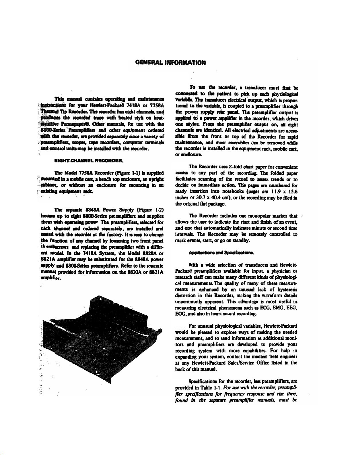
1-1. Introduction..............1-1
1-3. Eight-Channel Recorder..........1-1
1-9. Application and Specifications.......1-1
1-13. Accounts and Optics 1-2.
1-15. Preamplifier 1-2
SECTION II. INSTALLATION..........2-1
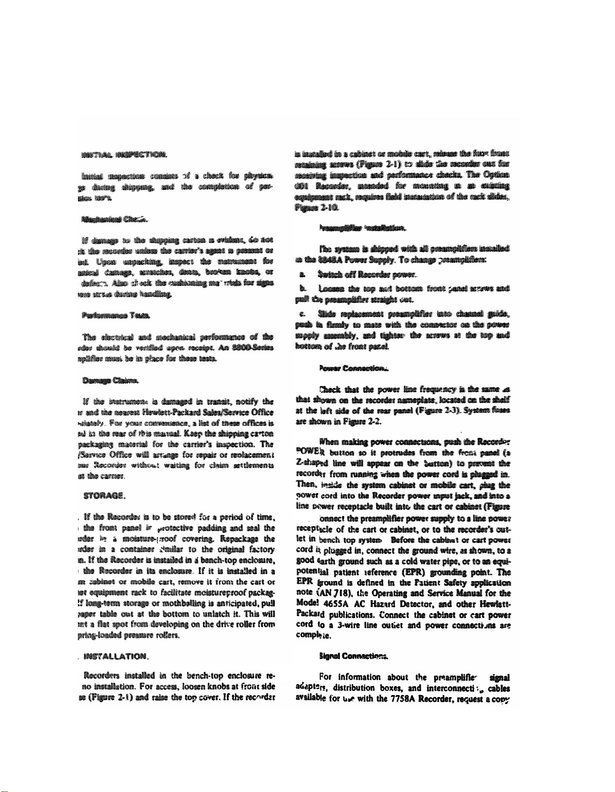
2-1. Initial Inspection.........2-1
2-3. Mechanical Check..........2-1
2-5. Performance Tests.............2-1
2-7. Damage Claims..............2-1
2-9. Storage.......2-1
2-11. Installation ............2-1
2-13. Premaplifier Installation.........2-1
2-15. Power Connections.............2-1
2-18. Signal Connections............2-1
2-22. Remote Control and Marker Connections .,.2-4
SECTION III. OPERATION..........3-1
3-1. Introduction..........3-1
3-3. Control Locations.........3-2
3-5. System Operation.........3-3
SECTION IV. PRINCIPLES OF OPERATION
4-1. Introduction.........5-2
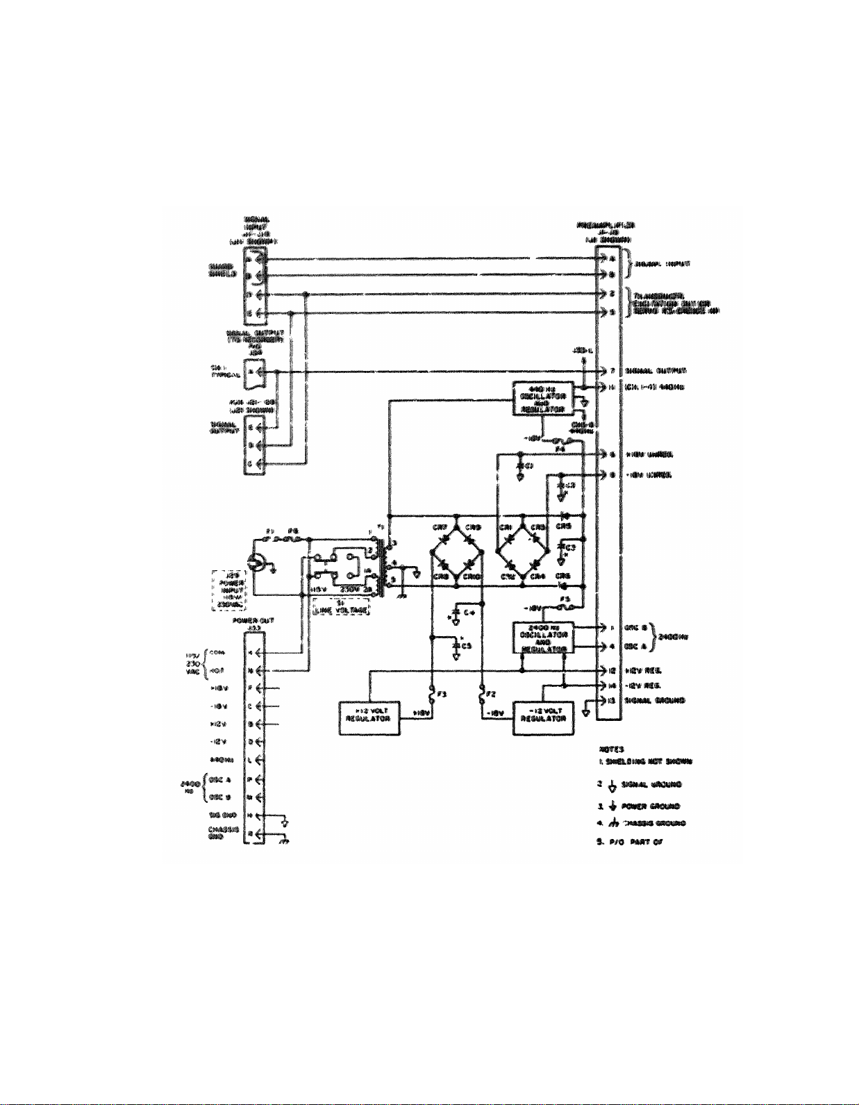
4-4. Preamplifier Power Supply 8848A.....4-0
4-7 Guarded Input Circuits..........4-1
4-9. Unregulated 18 Volt Supplies.......4-1
4-11. Preamplifier Supplies...........4-1
4-13. Oscillator Supply..........4-1
4-14. Regulated 12 Volt Supplies.........4-1
4-16 regulator Assembly..........4-1
4-18. 440 Hz Oscillator...........4-2
4-21. 2400 Hz Oscillator............4-2
4-24. Recorder Signal Circuits..........4-4
4-28. Galvanometer Dumping..........4-4
4-30. Damping.........4-4
4-31. Stylus Linkage.........4-4
4-33. Galvanometer Position Feedback.......4-7
4-37. Host Control Circuit........4-8
4-39. Power Control Circuits..........4-8
4-43. Chart Drive...............4-8
4-45. Chart Motor..............4-8
4-47. Speed Control............4-8
4-50. Speed Selection Solenoids.......4-11
4-51. Power Flow...............4-11
4-52. Paper Feed...........4-11
Page
Paragraph
4-54.
4-56.
4-58.
4-60.
4-61.
4-62.
4-63.
4-64.
4-66.
4-69.
4-70.
SECTION V. MAINTENANCE............5-1
5-1.
5-3.
5-5.
5-8.
5-10.
5-12.
5-16.
5-18.
5-20. Electrical Checks............5-4
5-22.
5-24.
5-26.
5-27.
5-28.
5-29.
5-31. Stylus Pressure Adjustment
5-32. Stylus Center Adjustment
5-33. Stylus Parallax Adjustment
5-34.
5-35. Stylus Removal and Replacement
5-37.
5-38.
5-40.
5-43.
5-46. Paper Table Disassembly
5-48.
5-49. Pressure Roller Replacement
5-50. Drive Roller Replacement
5-51.
5-53.
5-54. Gearbox Removal
5-55.
5-56.
Page
Recorder Power Supply and Regulator
Circuits.........4-13
Recorder DC Power Supplies.......4-13
Regulator/Oscillator..........4-13
+5 Volt Regulator...........4-13
+12 Volt Regulator......4-13
_12 Volt Regulator...........4-13
200kHz.................4-13
Oscillator Regualtion Circuit.......4-13
Marker Circut...........4-13
Marker Switches.......4-14
Marker Heat Driver...........4-14
Introduction.............5-1
Test Equipment and Lubricants........5-1
Performance Checks....................5-1
Variable Line Voltage...........5-2
Proventive Maintenance.........5-2
Operational Checks and Inspection.....5-2
Cleaning...............5-4
Lubrication.............5-4
Adjustments and Minor Repairs........5-4
Paper Drive Adjustments.........5-4
Paper Tracking Adjustment
Paper Timing Check
Paper Tension Adjustment
Stylus Adjustments
Channel Time Synchronization
Stylus Lapping
Corrective Maintenance
Galvanometer Removal and Replacement . 5-20
Drive Unit Removal and Replacement
Platen Replacement
Gerbox Removal and Overhaul
Gearbox Inspection
Gearbox Disassembly and Lubrication
(Overhaul)
Gearbox Lubrication
...........5-17
............
...............
.......
..........5-17
.......
.......
........
......
.....
...........
...........
.........
...........
......
........
.....
...........
..........
....
. . 5-22
5-17
5-17
5-17
5-18
5-19
5-19
5-19
5-20
5-20
5-24
5-24
5-24
5-24
5-27
5-27
5-27
5-28
5-28
i
Page 5

TM11-6625-2752-14&P
TABLE OF CONTENTS
Paragraph
5-57.
5-58.
5-59.
5-61.
5-62.
Gearbox Reinstallation. . . .5-31
Gearbox Run-In. . . . . . . . . . . . . . .5-34
Marker Assembly Maintenance. . . . . . . . . .5-34
APPENDIX
Figure
1-1
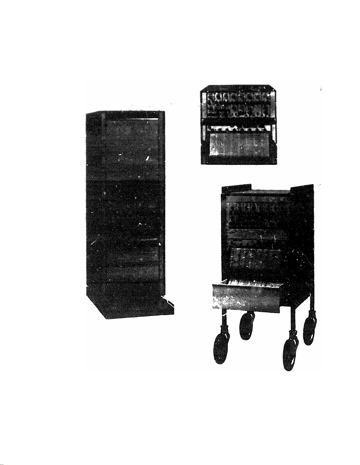
Model 7758A and 7418A Recording
Systems. . . . . . . . . . . . .1-0
8848A Preamplifier Power Supply. . . . . . .1-1
1-2
2-1.
2-2
2-3.
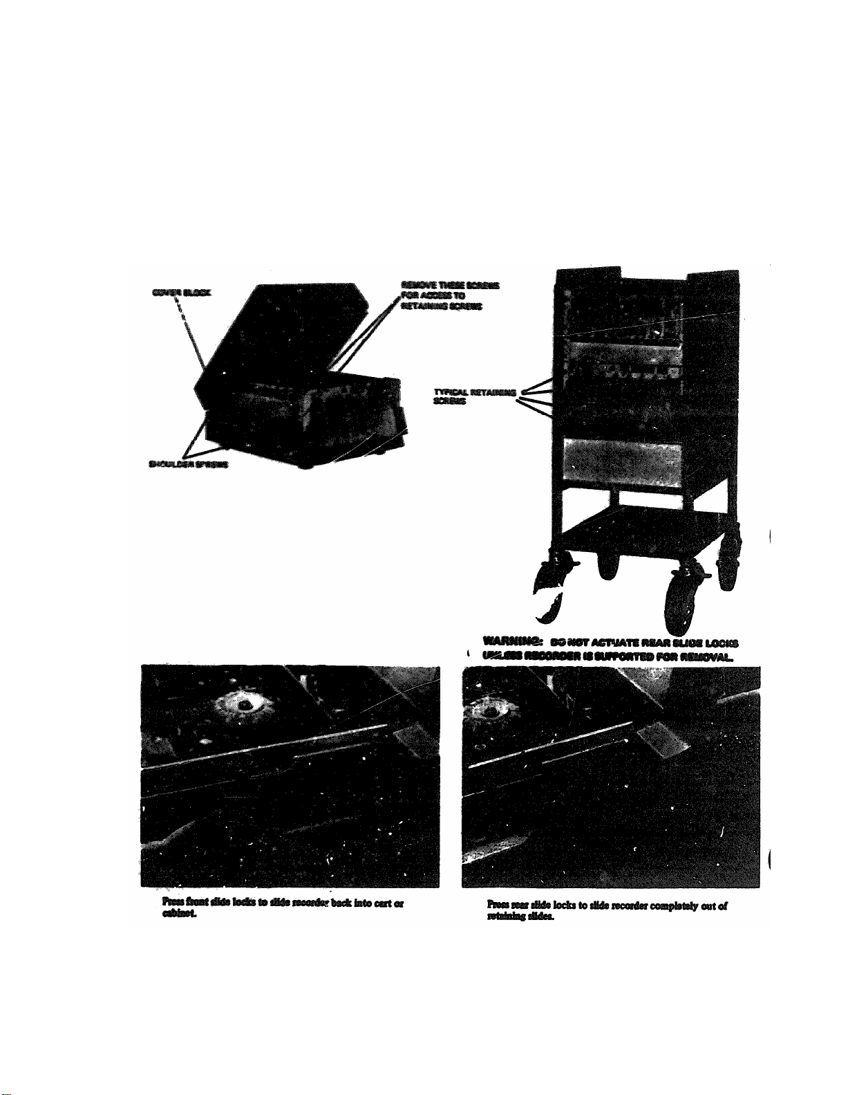
Recorder Access for Receiving Inspection . . . .2-2
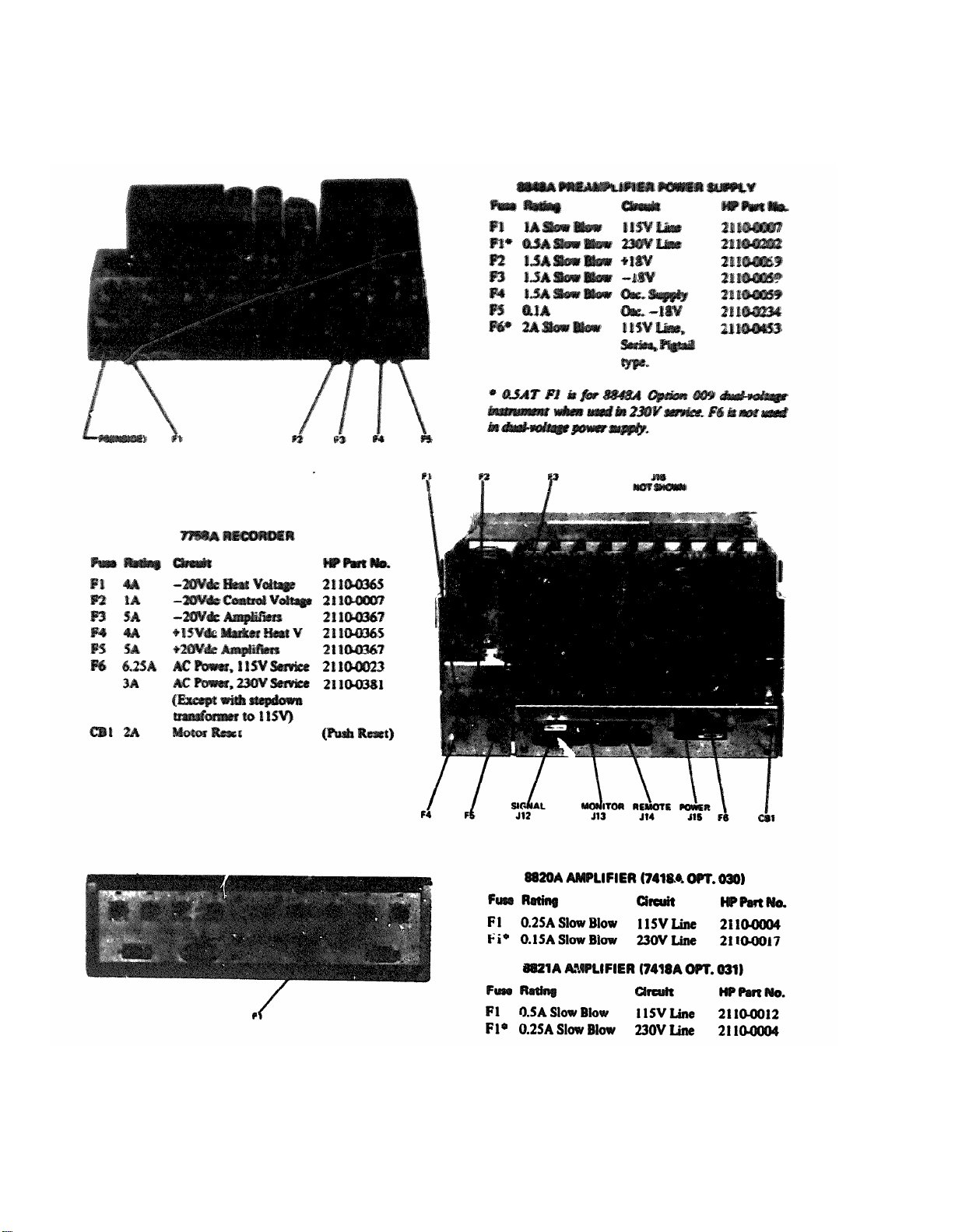
Rear Panel Connectors and Fuses. . . . . . . . .2-3
Recorder and Mobile Cart Power
Connections. . . . . . . . . . . .2-4
2-4.
1065-Series Cabinet Power Module and
Schematic Diagram (typical). . . . . . . . . . 2-5
2-5.
2-6.
Output Adapter 14208A, 142088. . . . . . . .2-6
System Connection (with Control Section
4682A). . . . . . . . . . . . . 2-7
2-7.
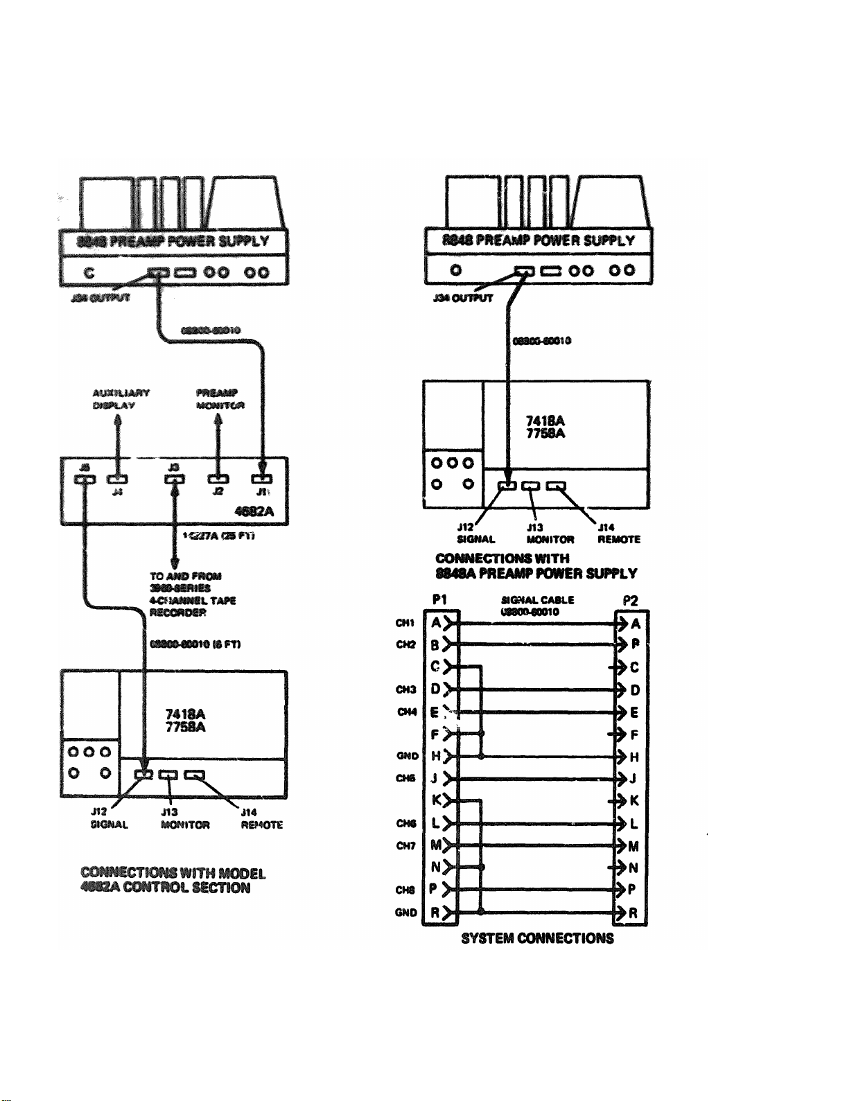
Preamplifier Power Supply 884A. Input and
Output Connection. . . . . . . . . . . 2-8
2-8.
7418A System Input Cable Preparation (Multi- Text
channel Amplifier Options 030, 031). . . . . . 2-9
Cabel and Connector Assembly Diagrams for
2-9.
SIGNAL, MONITOR, and REMOTE Rear
Panel Connectors, Models 7758A, 7418A. 2-10
Option 001, 010 Mounting Kit 07758-60400 2-11
2-10.
3-1
4-1.
Control Locations. . . . . . . . . . .3-1
3-2.
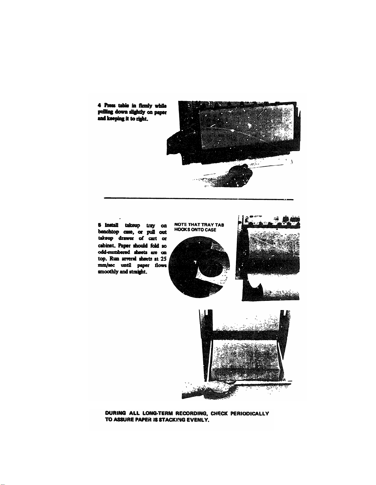
Paper Loading Procedure. . . . . . . 3-2
Preamplifier Power Supply., Simplified
Diagram. . . . . . . . . 4-0
4-2.
12-Volt Regulator Circuit Power
Supply 8848). . . . . . . . . . . 4-2
4-3.
440 Hz Oscillaotr Circuit (Preamplifier Power
Supply 8848A). . . . . . . . . . . 4-3
4-4.
2400 Hz Oscillator Circuit (Preamplifier Power
Supply 8848A). . . . . . . . . . . 4-3
4-5.
4-6.
Galvanometer Damping. . . . . . . . . .4-4
Recorder Signal Circuits, Simplified Diagram. . .4-5
ii
Page
Gearbox Shift Play Adjustment. . . . 5-31
Paragraph
SECTION VI. REPLACEABLE PARTS. . . . . . . . 6-1
Page
Solanoid Adjustment. . . . . . . . . . . . . .5-31
Introduction. . . . . . . . . . . . . . .6-1
6-1.
6-4.
Reference Designations. . . . . . . . . . . . . . . . 6-1
6-10.
Ordering Information. . . . . . . . . . . . . . . .6-2
A .DIFFERENCE DATA SHEETS. . . . . . . . . . . . . . . . . . . .A-1
B. DIFFERENCE. . . . . . . . . . . . . . . . . . . . . B-1
C. MAINTENANCE ALLOCATION. . . . . . . . . . . . . . . . . . . . .C-1
D. REPAIR PARTS AND SPECIAL TOOLS LIST. . . . . . . . . . . . . .D-1
LIST OF ILLUSTRATIONS
Page
Figure Page
4-7.
4-8.
4-9.
Model 7758A, 7418A Recorder, Block Digagram 4-6
Galvanometer Position Feedback Circuit. . . 4-7
Recorder Power Control Circuit, Simplified
Diagram. . . . . . . . . . . . . .4-9
4-13.
Chart Drive Gears. v. . . . . . . . . . . . .4-9
Gearbox Power Flow. . . . . . . . . . . . 4-10
Paper Feed Path. . . . . . . . . . . .4-11
Recorder Power Supply and Regulator Ciruits,
4-10.
4-11.
4-12.
Simplified Diagram. . . . . . . . . .4-12
4-14.
Marker Heat Driver Output Current
Waveforms. . . . . . . . . . .4-14
Recorder Test and Adjustment Points. . . . .5-3
5-1
Recorder Lubrication Points (Typical). . . . . . . .5-5
5-2
5-3
Preamplifier Power Supply 8848A, Power
Test Points, Test Cable. . . . . . . . . .5-7
5-4.
5-5.
5-6.
5-7.
5-8.
5-9.
5-10.
5-12.
5-13.
Test Cable and Fixture. . . . . . . . . . . .5-8
Driver or Regulator Board Test Setup. . . . . .5-9
Regulator/Oscillator Board Test Points. . .5-11
Driver Amplifier Board Test Points. . . . . . .5-14
Paper Tension Adjustment. . . . . . . . . .5-18
Stylust Adjustments. . . . . . . .5-19
Channel Time Synchroniztic Adjustment 5-20
Stylus Removal and Replacement. . . . .5-21
5-11.
Stylus Lapping Procedure. . . . . . . . .5-22
Drive Unit and Galvanometer Mounting
Screws. . . . . . . . . . . . . . . . . .5-23
Drive Unit Removal and Replacement. . .5-24
5-14.
5-15.
Paper Removal, Table Link and Drive
Roller Disassembly. . . . . . . . . . 5-25
Gearbox Removal. . . . . . . . . . .5-26
5-16.
5-17.
5-18.
5-19.
5-20.
5-21.
Gearbox Disassembly. . . . . . . . .5-29
Clutch Lubrication. . . . . . . .5-30
Gearbox Shaft End Play Adjustment. . . . . . . 5-31
Gearbox Solenoid Adjustmentl. . . . . . . . . .5-33
Marker Assembly Adjustment and Removal 5-34
Page 6
LIST OF FIGURES
TM11-6625-2752-14&P
Figure
6-1.
6-2.
6-3.
6-4
6-5.
Page
6-3
6-22
6-22
6-23
Figure
6-18
6-19
6-20.
6-21.
6-23
6-6.
6-7.
6-8.
6-9.
6-10.
6-24
6-25
6-26
6-27
6-28
6-22.
6-23.
6-24.
6-11.
6-29
6-25.
6-12.
6-30 6-26.
6-13.
6-14
6-15.
6-16.
6-31
6-31
6-32
6-33
6-27.
6-28.
6-17.
6-33
6-29.
Page
6-34
6-35
6-35
6-36
6-41
6-41
6-42
6-42
6-43
6-43
6-44
6-45
Table
Page
1-1.
1-2.
1-3.
5-1.
5-2.
5-3.
1-2
1-3
1-4
5-1
5-2
5-6
Table
5-4.
5-5.
6-1.
6-2.
6-3.
Page
5-9
5-32
6-4
6-21
6-36
6-4.
6-40.1
iii
Page 7
TM11-6625-2752-14&P
Section I - Channel Information
Models 7758A, 7418A
07758-1
1-0
Figure 1-1. Model 7758A and 7418A Recording Systems
Page 8
SECTION O
0-1. SCOPE.
0-2. INDEXES OF PUBLICATIONS.
0-3. FORMS AND RECORDS.
TM11-6625-2752-14&P
0-4. REPORTING EQUIPMENT IMPROVEMENT (EIR).
0-1
Page 9
TM11-6625-2572-14&P
0-5. ADMINISTRATIVE STORAGE.
0-2
Page 10
INTRODUCTION.
1-1.
1-2.
1-3.
1-4.
SECTION I
1-6.
1-7.
TM11-6625-2752-14&P
Section I - General Information
Models 7758A, 7418
07758-1
1-5.
1-8.
1-9.
1-11.
Figure 1-2. Preamplifier Power Supply
1-12.
1-1
Page 11
TM11-6625-2752-14&P
SECTION I. General Information
Models 7758A, 7418A
07758-1
1-13.
1-14.
1-15.
1-16.
1-17.
Table 1-1. Specifications
1-2
Page 12
Table 1-1. Specifications (continued)
TM11-6625-2752-14&P
SECTION I -
General Information
Models 7758A, 7418A
07758-1
Bench Enclosure (Accessory
(30.2 cm). Width, 20.25 in. (51 cm). Depth, 24 in.
(60.5 cm). Paper Takeup Tray projects 11.5 in. (29.2
cm) from front enclosure and hangs down 5.5 in.
(13.8 cm).
Mobile Cart: Height, 50.5 in. (128 cm). Width, 21.5
In. (55 cm). Depth, 26 in. (67 cm). Paper Takeup
Tray projects 11.5 in. (29.2 cm). Add 6 in. (15 cm)
to
WEIGHT: Recorder alone: 110 lb (49.9 kg including
driver amplifiers. With bench top enclosure: 128 lb
(58 kg). In mobile cart with power supply, but less
preamplifier: 354 lb (160 kg).
Each Channel: Position (10 div trim), Gain,
Damping, High Limit, Low Limit.
POWER REQUIREMENTS: 60 Hz or 5O Hz (option-
al), 115/230 Vac), 10% Power consumption is less
-than 5A in 115 Vac operation. Warmup Time:
Approximately
DIMENSIONS:
ENVIRONMENT: Maximum ambient temperature
(free air circulation) 40 C (104 F); if blocked from
free air flow, 25 C (77 F). Location should be
reasonably free from dust, explosive or corrosive
vapors, and extreme cold.
C0NNECTIONS: Signal Input J12 for preamp signals
from power supply. Through Signal Monitor J13,
preamplifier outputs for monitor scope, tape, and
Recorder Alone: Height, 10.5 in. 26.6 (cm) Width,
19.0 in (483 cm), for standard RETMA equivalent
rack. Depth, 22.75 in. (57.3 an). Projects 2.5 in. (6.3
an) from front of rack.
inputs, low voltage dc power and remote control
functions.
Width
or Depth for caster projections
devices are available at the rear
to preamplifier inputs and auxiliary
): Height, 11.875 in.
Table 1-2. 8848A Preamplifier Power Supply
Regulated Outputs:
+12Vdc at 800 mA maximum.
- 12Vdc at 800 mA maximum.
Ripple not more than 4 mV under full load.
Unregulated outputs:
+18Vdc at 600 mA maximum.
-18Vdc at 600 mA maximum.
(Current capacity is 1.4 amperes minus current
supplied by regulated output circuits.)
Power Requirements:
115 or 230 volts (switch provided), 50 to 400
Hz, 120 watts full load.
Specifications
Oscillator Outputs:
440 Hz + 2% floating, 14Vac peak-to-peak, 4
watts maximum. Amplitude stability + 5%.
2400 Hz 2% floating, 10Vac rms, 50 mW
maximum. Amplitude stability + 5%.
Weight:
About 26 lbs. (11,8 Kg) less preamplifiers.
Dimensions:
7 in. high x 19 in. wide x 2O in. front-to-back
(178x483x521 mm).
1-3
Page 13
TM11-6625-2752-14&P
SECTION I- General Information
Models 7758A, 7418A
00758-1
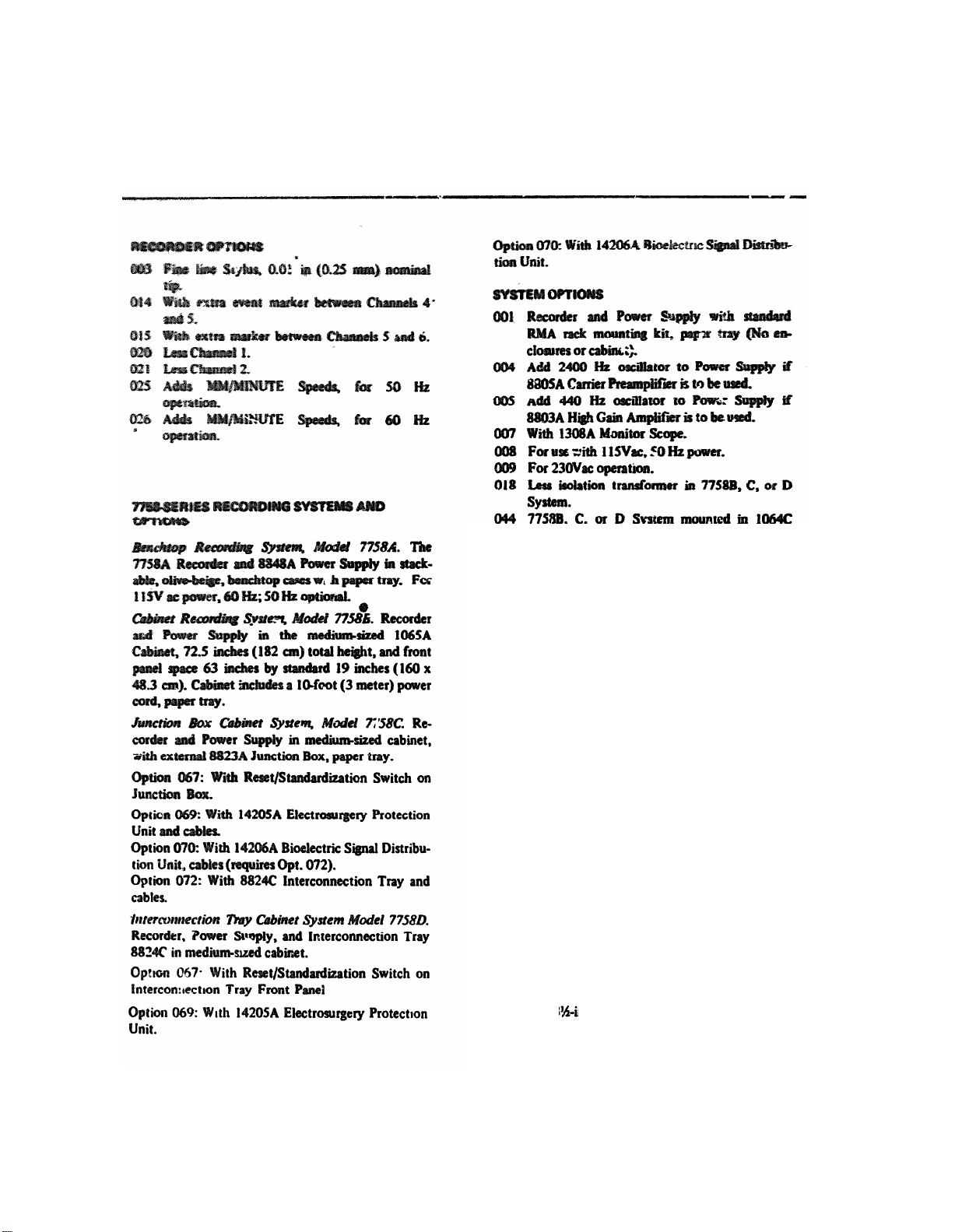
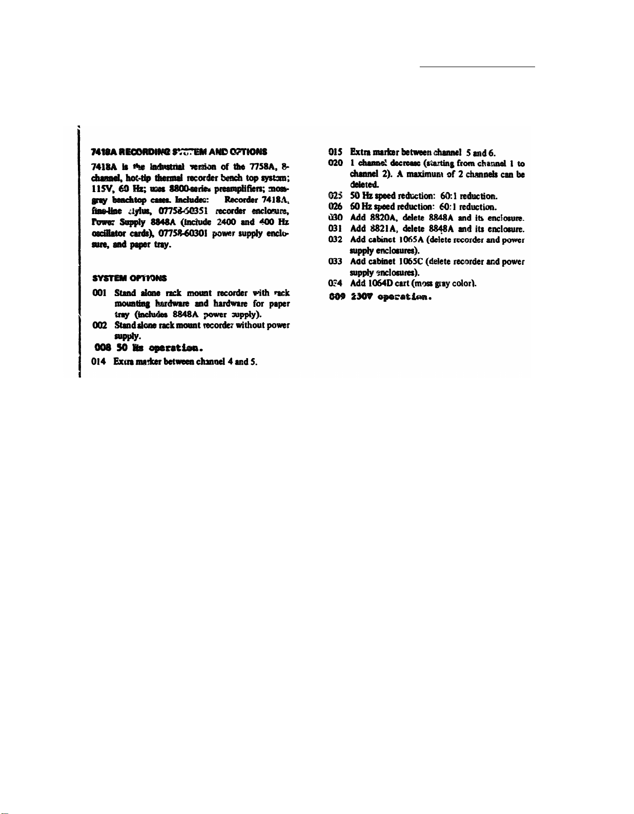
Table 1-3. Recorder Options and System Options
045 System installed in 1065B tall cabinet, with
051 With writing shelf on right side facing system
cabinet or cart.
052 With writing shelf on left side facing system
cabinet or cart.
053 With l top-mounted tilt stand for display on
1064C cart or 1065C short cabinet.
054
With 14217A Transducer Holder for two 1280Series Physiological Pressure Transducers,
mounts on IV Pole.
055 System installed in 1065C short cabinet, with
paper tray.
057
With 14217-6O010 mount for IV pole on right
side, facing cart or cabinet. Accepts 0.25 to
0.75 inch (0.63 to 1.9 cm) diameter IV pole.
Includes pole for mounting Option 054 Trans-
ducer Holder.
058 Same as Option 057 except mounted on left
side.
078 Lass 8848A Power Supply and enclosure,
7758A System.
Less 8848A Power Supply, 7758B, C, or D
System.
079 Add Power Supply Enclosure for 77588
system.
080 Replace paper takeup tray with 7-inch high
paper takeup drawer on rack mount slides.
081 Add 3 inch supply drawer.
082
Add 7-inch supply drawer.
1-4
Page 14
TM11-6625-2752-14&P
SECTION I-General Information
Table 1-3 Recorder Options and System Option (continued)
Models 7758A, 7418A
07758-1
1-5
Page 15
2-1.
2-3.
2-4.
2-5.
2-6.
TM11-6625-2752-14&P
Section II -Installation
Module 773A, 7412A
SECTION II
2-13.
2-14.
23758-1
2-7.
2-8.
2-9.
2-10.
2-11.
2-15.
2-16.
2-17.
2-3)
2-18.
2-12.
2-19.
2-1
Page 16
TM11-6625-2752-14&P
Section II.-Installation
Module 7758A, 7418A
87738-1
2-2
Figure 2-1. Recorder Access for Receiving Inspection
Page 17
TM11-6625-2752-14&P
Section II.-Installation
Module 7758A, 7418A
07728-1
Figure 2-2. Reer Panel Connectors and Fuses
2-3
Page 18
TM11-6625-2752-14&P
Section II-Installation
Module 7758A, 7418A
07158-1
2-20.
2-21.
2-4
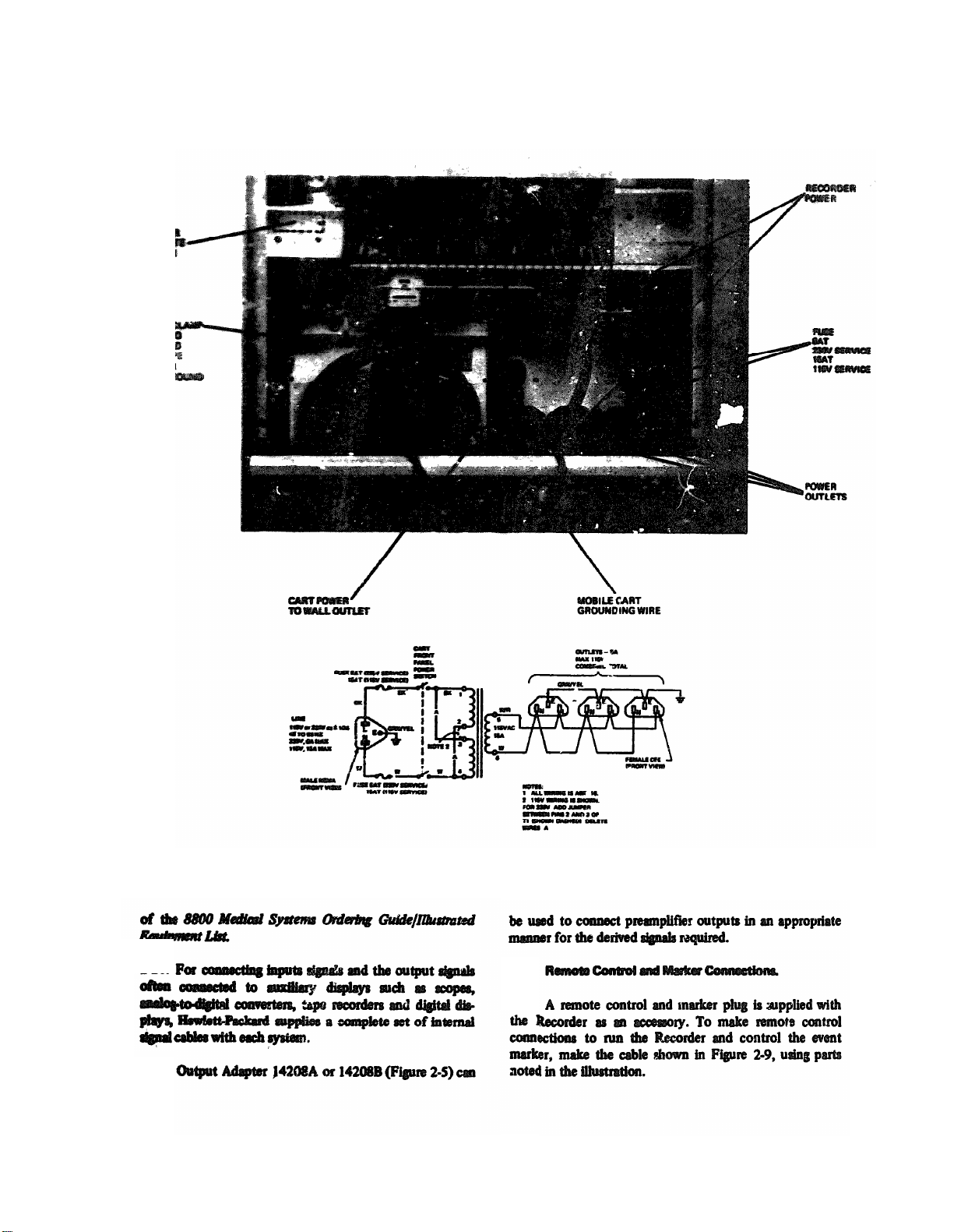
Figure 2-3. Recorder and Mobile Cart Power Connections
2-22.
2-23.
Page 19
TM11-6625-2752-14&P
Section II-Installation
Module 7758A, 7418A
07758-1
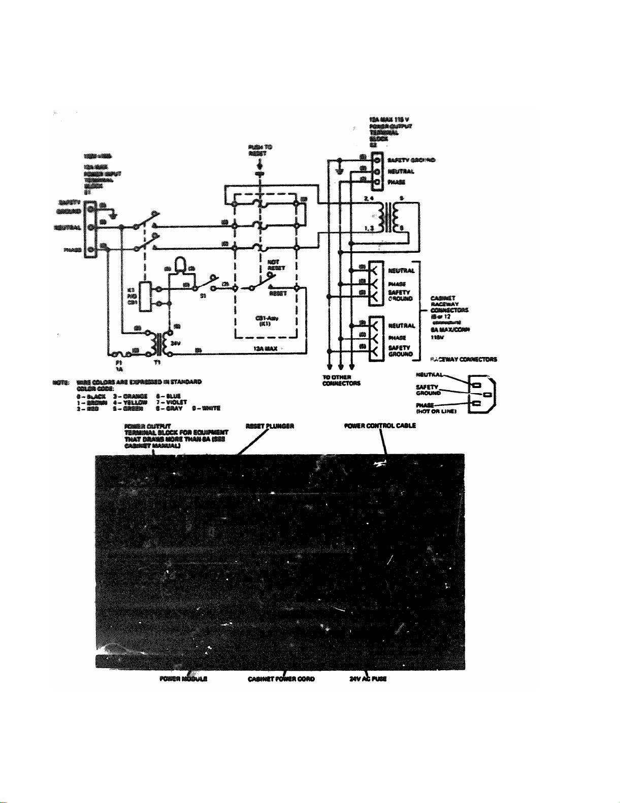
Figure 2-4. 1085-Series Cabinet Module and Schematic Diagram (typical)
2-5
Page 20
TM11-6625-2752-14&P
Section II-Installation
Module 7758A, 7418A
07758-1
2-6
Figure 2-5. Output Adapter 14208A, 14208B
Page 21
TM11-6625-2752-14&P
Section II-Installation
Module 7758A, 7418A
07758-1
Figure 2-6. System Connections (with Control Section 4682A)
2-7
Page 22
TM 11-6625-2752-14&P
Section II - Installation
2-8
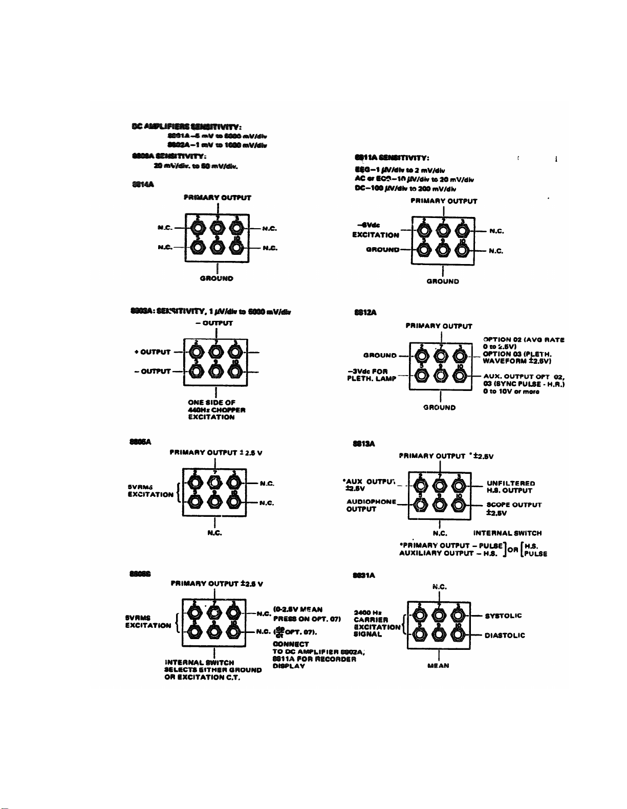
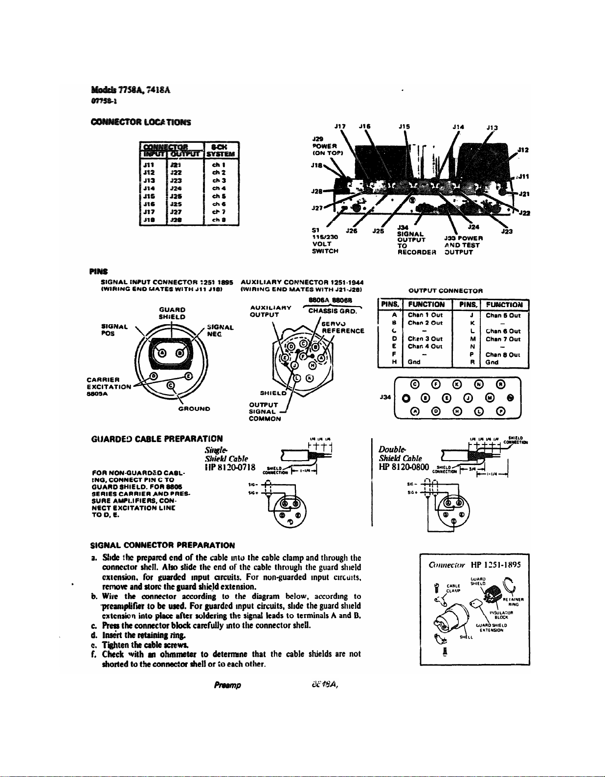
Figure 2-7.
lifier Power Supply Input and Output Connections
Page 23
TM 11-6625-2752-14&P
Section II - Installation
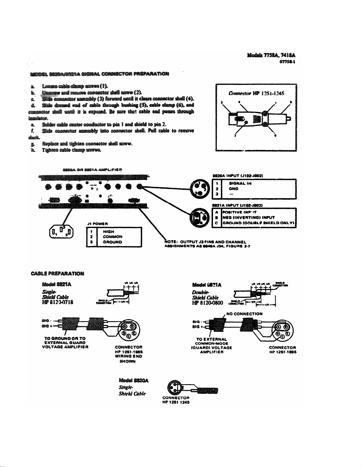
Figure 2-8. 7418A System Input Cable Preparation (Multichannel Amplifier Options 030, 031)
2-9
Page 24
TM11-6625-2752-14&P
Section II-Installation
Models 7758A,7418A
07758-1
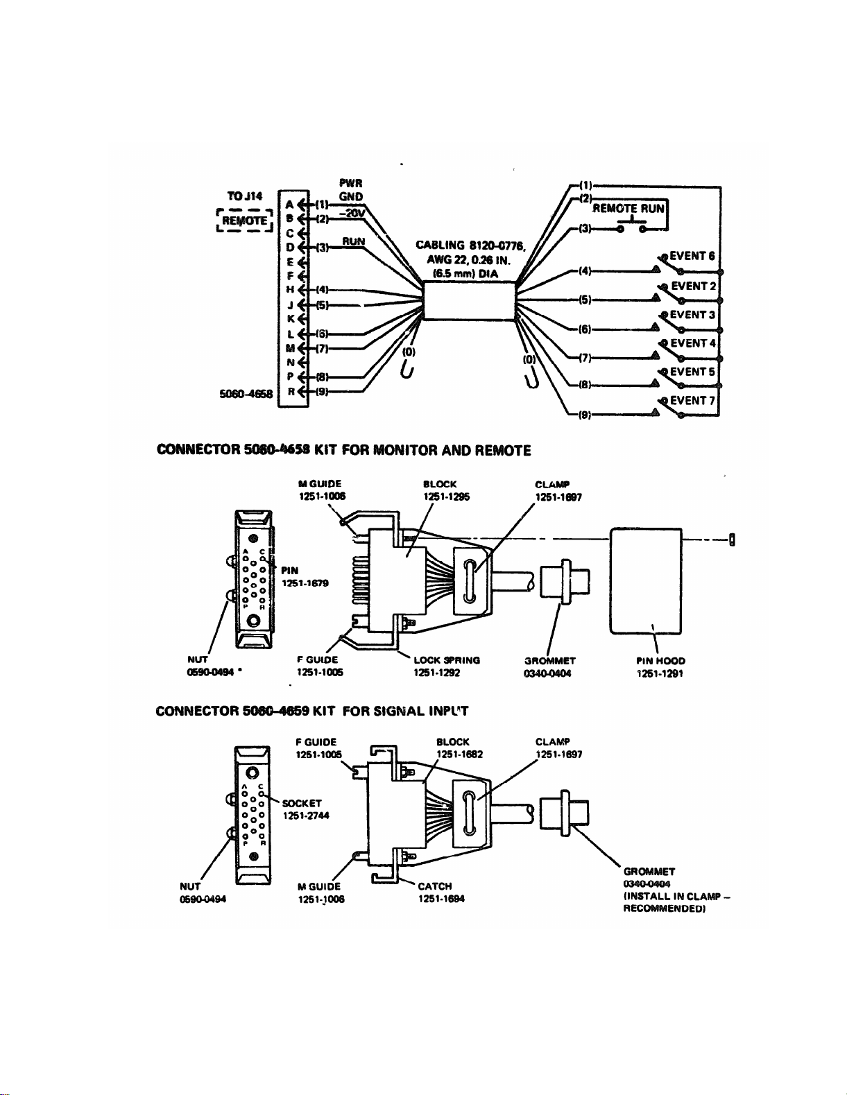
Figure 2-9. Cable and Connector Assembly Diagrams for SIGNAL, MONITOR and REMOTE Rear Panel Connector
Models 7758A, 7418A
2-10
Page 25
TM11-6625-2752-14&P
Section II-Installation
Models 7758A, 7418A
07758-1
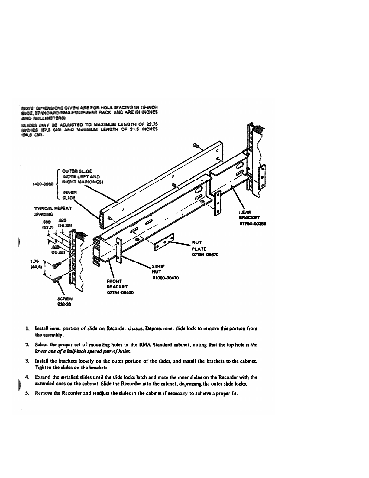
Figure 2-10 Option 001,010, Mounting Kit 07758-60400
2-11
Page 26
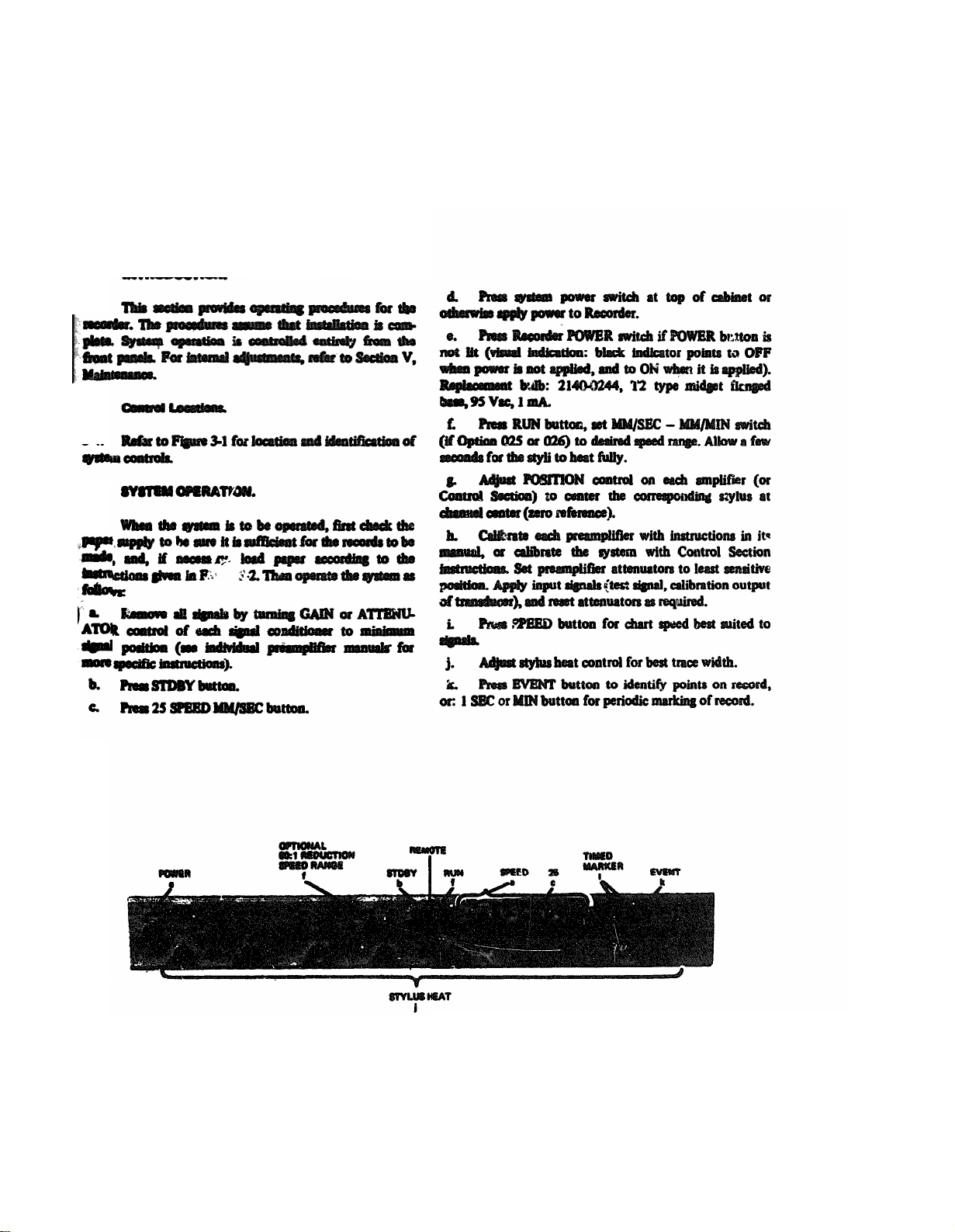
3-1. INTRODUCTION..
3-2.
3-3.
3-4.
3-5.
3-6.
SECTION III
OPERATION
TM11-6625-2752-14&P
Section III-Operation
Models 7758A, 7418A
07758-1
Figure 3-1. Control Locations
3-1
Page 27
TM11-6625-2752-14&P
Section III-Operation
Models 7758A, 7418A
07758-1
3-2
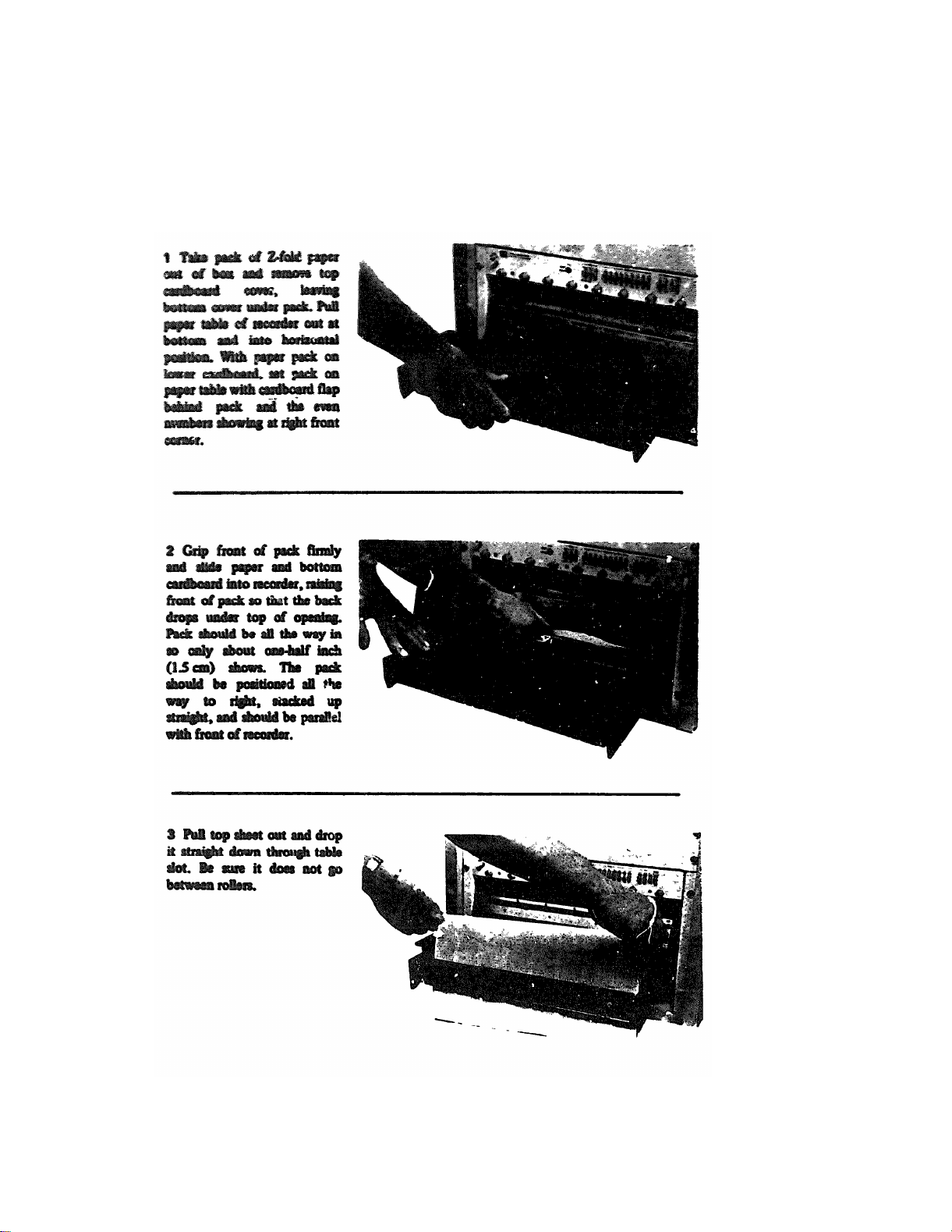
Figure 3-2. Power Loading Procedure, Models 7758A. 7418A
Page 28
TM11-6625-2752-14&P
Section III-Operation
Models, 7758A, 7418A
07758-1
CAUTION
Figure 3-2. Paper Loading Procedure, Models 775BA, 7418A (continued)
3-3
Page 29
TM11-6625-2752-14&P
Section IV- Principles of Operations
Models 7758A, 7418A
00758-1
4-0
Figure 4-1. Preamplifier, Power Supply, Simplified Diagram
Page 30
SECTION IV
PRINCIPLES OF OPERATION
TM11-6625-2752-14&P
Section IV-Principles of Operation
Models 7758A, 7418A
07758-1
4-1. INTRODUCTION.
4-2.
4-3.
4-7.
Guarded Input Circuits.
4-8.
4-9. Unregulated 18 Volt Supplies.
4-10.
4-11.
4-4. PREAMPLIFIER POWER SUPPLY 8848A.
4-5.
4-1
4-6.
4-13.
4-14.
4-15.
4-16.
4-1
Page 31

TM11-6625-2752-14&P
Section IV-Principles of Operation
Models 7758A, 7418A
00758-1
4-17.
4-20.
4-21.
4-18.
4-19.
4-22.
4-2
Figure 4-2. 12-Volt Regulator Circuit (Preamplifier Power Supply 8848A)
Page 32

TM11-6625-2752-14&P
Section IV-Principles of Operation
Models 7758A, 7418A
Figure 4-3. 440 Hz Oscillator Circuit (Preamplifier Power Supply 8848)
07758-1
4-23.
Figure 4-4. 2400 Hz Oscillator Circuit Preamplifier Power Supply 8848A)
4-3
Page 33

TM11-6625-2752-14&P
Section IV-Principles of Operation
Models 7758A, 7418A
07752-1
4-24.
4-25.
4-26.
4-27.
4-28.
4-29.
4-30.
4-31.
4-32.
4-4
UNDERDAMPED
Figure 4-5. Galvanometer Damping
Page 34

TM11-6625-2752-14&P
Section IV-Principles of Operation
Models 7758A, 7418A
07758-1
Figure 4-7. Model 7758A/7418A Recorder, Block Diagram
4-6
Page 35

TM11-6625-2752-14&P
Section IV-Principles of Operation
Models 7758A, 7418A
07758-1
Figure 4-6. Recorder Signal, Circuits, Simplified Diagram
4-5
Page 36

TM11-6625-2752-14&P
Section IV-Principles of Operation
Models7758A, 7418A
07758-1
4-33.
4-.34.
4-35.
Figure 4-8. Galvanometer Position Feedback Circuit
4-7
Page 37

TM11-6625-2752-14&P
Section IV-Principles of Operation
Models 7758A, 7418A
07758-1
4-36. An example of unbalance is shown in Figure 4-8. As
the positive signal causes the galvanometer to move the
stylus as shown, the rotor moves so that more of the
oscillator output is felt on the split capacitor
plates/. These plates are connected to the CR1-Q1 half of
the demodulator, so that more positive voltage is impressed
upon C1. The unshaded plates receive proportionately less
of the oscillator output, and so CR2-Q2. the negative side
of the demodulator, produces less positive output for C1.
C1, then, sends a positive feedback voltage to the driver
amplifier, which tends to return the stylus toward the
center of the chart. The feedback voltage is sided by a
torsion spring that facilitates setting of the sylus mechani-
cal center. For maintenance purposes, note that one volt of
position voltage corresponds to 10 division s of stylus
movement
4-37.
4-38.
Stylus heat is controlled from the Heat Pot Board,
A2A2, on the front panel. The heat control voltage is
applied to a simple feedback amplifer located on the driver
amplifier assembly. Q11, Q12, and Q13, which has a
current limiting circuit similar to that used for the
galvanometer. The amplifer output drives the resistive
stylus heat element. A good stylus should have about 34
ohms resistance.
4-39. Power Control Circuits
works, the -20V supply voltage, applied to
to the switch via
the main feeder line at the top of Figure 4-9 energizes the
center contacts of the switch segment. /when the push-
button marked "5" is depressed, -20V is applied to
solenoids. L3 and L4 through diodes CR5 and CR6,
respectively, aelecting the
speeds of 5 mm/sec
ted
by fixed voltages applied to the heat control
proper gear combination
and higher, the
heat control voltage is
In
potentiometers by the control switch. The heat control
potentiometer setting permits front panel adjustment of the
trace density through the heat control circuit each driver
amplifier.
4-43. CHART DRIVE.
4-44. The recorder chart drive consists of a 115 volt ac
motor, a gearbox with four pairs of clutches and speed
selection solenoids, a paper drive roller, and a paper brake.
4-45. Chart Motor.
4-46. The chart motor is a continuous duty, synchronous
motor with a speed of 1800 rpm for 60 Hz operation. A
pulley on the motor shaft engages a drive belt
that
transmits power to the gearbox. To provide additional
electrical safety, the motor IS Insulated from the recorder
chassis by non-conducting spacers.
4-40. Power IS controlled from the recorder front panel.
Figure 4-9 shows recorder power switching together with
chart motor control circuits and speed control solenoid
circuit.
4-41
Line common reaches the chart drive motor through
Sl, the power switch and the Ul voltage selector, whenever
Sl IS on. The high side of line power IS applied to the chart
drive motor through motor relay Kl, which is actuated
by
the control switch RUN button on the front panel, or
a remote run signal (Figure 2-9). The motor is described
further in Paragraph 4-46. Kl also turns on
stylus
heat
through the control switch.
4-42. The motor drives the gearbox, the speeds of which
are controlled by speed selection solenoids Ll, L2, L3, and
L4. The speed control action of these solenolds is described
in Paragraph
4-51. The segments of the control switch are
so arranged that the solenoids are energized in the correct
combinaiton for each speed desired. The switch IS
shown in
the 5 mn/sec position. As an example of how the switch
4-8
4-47.
4-48.
Control.
Chart paper speed IS varied by a gear train consisting
of sets of four gears, on two shafts (Figure 4-10) These
shafts are fixed in place and do not rotate. Each set of four
gears (A, B, C, and D) either provides a speed reduction
with all four gears transmitting power, or no speed
reduction, with power bypassing the reduction gears
through a spring clutch that links gears A and D on the
primary shaft. Gear D IS mechanically part of Gear, A on the
next set, so power IS directly transmitted to the next set of
gears
When direct drive is desired, the associated solenoid
4-49
is energized, withdrawing the plunger from the clutch
pawls. The clutch then engages, coupling gears A and D
The spring clutch between gears B and C automatically
disengages since gear C, being smaller than gear B, rotates
faster when gears A and D are in direct drive
Page 38

Figure 4-9. Recorder Power Control Circuits, Simplified Diagram
Figure 4-9.
Page 39

TM11-6625-2752-14&P
Section IV- Principles of Operations
Models 7758A, 7418A
07158-1
Recorder Power Control Circuits, Simplified Diagram
Figure 4-9.
Figure 4-10. Chart Drive Gears
4-9
Page 40

TM11-6625-2752-14&P
Section IV-Principles of Operation
Models 7758A, 7418A
07758-1
4-10
Page 41

TM11-6625-2752-14&P
Section IV-Principles of Operation
Models 7758A, 7418A
07758-1
Figure 4-11. Gearbox Power Flow
4-10
Page 42

4-50.
4-51.
TM11-6625-2752-14&P
Section IV-Principles of Operation
Models 7758A, 7418A
07758-1
4-52.
4-53.
Figure 4-12. Paper Feed Path
4-11
Page 43

TM11-6625-2752-14&P
Section IV-Principles of Operation
Models 7758A, 7418A
07758-1
4-12
Figure 4-13. Recorder Power Supply and Regulator Circuits, Simplified Diagram
Page 44

TM11-6625-2752-14&P
Section IV-Principles of Operation
Models 7758A, 7418A
07758-1
4-54.
4-55.
4-56.
4-57.
4-58.
4-59.
4-62.
4-63.
4-64.
4-60.
4-61.
4-65.
4-66.
4-67.
4-13
Page 45

TM11-6625-2752-14&P
Section IV-Principles of Operation
Models 7758A, 7418A
07758-1
4-68.
4-69.
4-70.
4-91. To switch the current, differential input circuit
is controlled by two things, to turn the current
on at the appropriate time. The height of the
output voltage pulse, and thus the quantity of current, is
determined by the heat control voltage level. It is limited
by the point at which the main +l5V supply starts (or
stops) drawing current. The differential circuit switches
series regulator Q18, Q12 to pulse the marker heat current
as drown by the shaded areas in Figure 4-14. This provides
a pulse on the steep leading and trailing edges of the main
waveform, when the capacitive supply is not drawing
current. Board exchange instead of troubleshooting is
recommended if this circuit IS found to be inoperative.
4-14
Figure 4-14. Marker Heat Driver Output Current Waveforms
Page 46

5-1.
5-2.
5-3.
5-4.
MAINTENANCE
Paragraph 5-5
Paragraph 5-10
Paragraph 5-20
Paragraph 5-22
Paragraph 5-38.
SECTION V
5-5.
5-6.
TM11-6625-2752-14&P
Section V-Maintenance
Models 7758A, 7418A
07758-1
Table 5-1. Recommended Test Equipment
To be made, see Figures 5-3, 5-4.
5-1
Page 47

TM11-6625-2752-14&P
Section V-Maintenance
Models 7758A, 7418A
07758-1
Table 5-2. Lubricants and Solvents Required
5-14. Operate the Recorder in all speed
perform the operating procedure, using all controls listed in
Figure 3-l.
5-15. The following steps check operation of the
Recorder:
a.
Recorder slides..
smoothly and that they lock in the full open position
(Figure 2-1).
5-7. To facilitate by checking the Driver Amplifiers and the
Regulator/Oscillator Assembly, extender boards (Table 5-1)
are available as accessories.
Paper tension: Run the Recorder at the highest
speed and inspect paper travel over the platen at the paper
table (see Figure 4-12). The paper should travel snugly over
the paper table. Adjust the paper brake if necessary, or
5-8.
Variable Line Voltage.
5-9.
During the performance
checks, the Recorder should
be connected to the power source through an adjustable
autotransformer so the line voltage can be changed 10%
from the nominal 115 or 230 Vac.
CAUTION
TO AVOID DAMAGE, REMOVE POWER FROM THE
RECORDER BEFORE DISCONNECTING ASSEMBLIES
OR COMPONENTS. NEVER TlP RECORDER ONTO
REAR PANEL AREA, TO AVOID DAMAGING THE
TRANSFER PC ASSEMBLY AND DRIVER
AMPLIFIERS.
5-10. PREVENTIVE MAINTENANCE.
5-11. Preventive maintenance is recommended every six
months or 1000 hours of operation, and new procedures
may be used as an aid for minor repairs, adjustments and
troubleshootmg.
5-12.
Operational Checks and Inspection.
5-13. Switch Recorder power OFF Inspect the Recorder
for evidence of mechanical or electrical overload, dents,
rust, and corrosion. Check that all components are securely
mounted, including the cable connectors Also check ex-
ternal connecting cables for strain, breaks, and frayed
insulation. If the Recorder is installed in a cart or cabinet,
the cables should be free when the Recorder is moved in
and out.
replace the brake felt (Paragraph 5-28).
C.
Paper tracking Run the Recorder at 25 mm/sec for
5 sheets. Paper should follow the right table guide without
weaving or damaging the edge of the paper. A static trace
position should not vary-more than 0.5 mm from any
reference grid line, after 6 to 12 sheets have passed and
tracking has settled down. Check several more sheets at 200
mm/second. For tracking adjustments, see paragraph 5-26.
d.
Galvanometer to Paper Parallax
will have the same time reference with respect to the paper,
all stylus tips must fall on the same time reference line of
the paper, 0.25 division. To check parallax, apply power
to the Recorder, and set to STANDBY mode. With finger
pressure, gently move the stylus off center full scale, in the
positive and negative directions The trace over the width of
each channel should be within 0. 25 mm of the reference
grid line. If not, see Paragraph 5-33 to adjust stylus
parallax. All 8 channels should be referenced to the same
grid line, that is, all traces should end at the same point
when the Recorder stops If not, see Paragraph 5-34
channel time synchronization procedure, which is used to
adjust galvanometer parallax, that is, to line up the
galvanometers in a straight line so the style will fall on the
same time line.
Signal Stylus.
e
and condition. If a stylus is bent or twisted, replace it
(Paragraph 5-35).
Stylus
f.
the trace lacks definition, but when pressure is too heavy,
friction causes noticeable non-linearity and hystereais
Refer to Paragraph 5-31 for stylus pressure adjustments.
WARNING
Check that the slides roll in and out
each signal stylus for cleanliness
Pressure
When stylus pressure is too light,
So that all channels
5-2
Page 48

TM11-6625-2752-14&P
Section V-Maintenance
Models 7758A, 7418A
07758-1
SIGNAL STYLUS
ADJUSTMENTS.
MARKER STYLUS
ADJUSTMENTS, SEE
SEE FIGURE 5-9 FlGURE 5-21
Figure 5-1.
Recorder Test and Adjustment Points
5-3
Page 49

TM11-6625-2752-14&P
Section V-Principles of Operation
Models 7758A, 7418A
07758-1
d.
Carefully clean the writing and marker stylus with
Chlorothene. Do not use steel wool or abrasive cleaning
compounds. Be careful not to bend the styli vertically , they
are easily distorted in the vertical direction.
5-18. Lubrication.
5-19. Minor lubrication should be performed during preventive maintenance Major lubncation (minor lubrication
plus gearbox) is done at overhaul and at regular intervals of
12 months or 2000 hours operation, if used mostly in the
upper half of the speed range. If the Recorder is used
mostly for low speed operation, more clutches are engaged
and
more reduction gears are used. Thus, a more
frequent
lubrication may be required, typically every 6 months or
1000 hours. To help assure uninterrupted service if an
extended period of recording is anticipated, overhaul and
lubricate the Recorder before placing it in service
Lubricants are listed in Table 5-2, lubrication points are shown in
Figure 5-2.
5-20. ELECTRICAL
5-21.
5-16. Cleaning
To check out the Model 8848A Power Supply, make
the cable shown in Figure 5-3, and follow the steps in Table
5-17. Depending on environmental conditions, cleaning
may be required at much shorter intervals than the regular
maintenance intervals:
Unplug Recorder power cord. Remove chart paper.
a.
Expose top
and rear of
Recorder, and remove dust with a
vacuum hose.
b.
Clean Recorder
and
Preamplifier front panels and
controls with a soft, lint-free cloth or a wax-impregnated
polishing cloth.
CAUTION
IF A SOLVENT IS
NECESSARY TO CLEAN THE
PANEL, USE ONLY CHLOROTHENE OR ETHYL ALCOHOL. OTHER SOLVENTS, SUCH AS ACETONE OR
ISO-PROPYL ALCOHOL, MAY REMOVE PANEL PAINT
5-3 To check out the 7758A or 7418A Recorder, follow
the procedure in Table 5-4 To facilitate checking, make the
cable shown in Figure 5-4 To support the Driver Amplifier
or Regulator, Oscillator for testing, fasten the PC board test
support shown in Figure 54 onto the rear of the heat sink
with a No 10 nut (Figure 5-5)
5-22. ADJUSTMENTS
5-23. Mechanical adjustments are confined to the
drive and galvanometer assemblies. Paper drive minor repair
and troubleshooting information is presented in Table 5-5
If necessary, galvanometer superficial parts may be replaced
only to the extent indicated in the Replaceable Parts List
Do not attempt to disassemble the Galvanometer, but
return it to Hewlett-Packard for service.
OR MARKINGS. IF THE PANEL MUST BE MARKED,
FOR INSTANCE WITH CHANNEL IDENTITY, USE
5-24. Paper Drive Adjustment
ONLY CHINA MARKING WAX CRAYON, OR COLORCODED EMBOSSING TAPE. DO NOT USE FELT.
NYLON, OR BAMBOO-TIPPED MARKERS ON THE
INSTRUMENT PANEL OR THE MARKING MAY DISCOLOR THE PANEL PAINT PERMANENTLY.
5-25. The rubber drive roller pulls paper over the
table, where it is aligned by the paper guide The pa
kept snug on the table by the paper brake felt, which
presses the paper against the back of the platen The paper
is kept from shipping on the drive roller by two spring-
Pull the paper table out at the bottom (Figure 3-2,
C.
Step I). Clean the surface of the paper table with
Chlorothene solvent.
metal pressure rollers with Chlorothene.
front
of
the
Under
bottom of the table, clean the
At
the bottom
Drive
Unit, clean the rubber drive roller with
Chlorothene (Figures 5-13, 5-15).
loaded pressure rollers To set up the Recorder so that
run on the channel centerlines, the paper is first adjusted to
run at the right edge of the paper guide, which is fixed in
location. Then the stylus position for each channel is
adjusted (see Table 5-4), the mechanical limit stops
adjusted, and the electrical limiters are adjusted
CHECKS.
AND
MINOR
REPAIRS.
5-4
Page 50

TM11-6625-2752-14&P
Section V-Maintenance
Models 7758A, 7418A
07758-1
Figure 5-2. Recorder Lubrication Points (Typical)
5-5
Page 51

TM11-6625-2752-14&P
Section V-Maintenance
Models 7758A, 7418A
07758-1
Table 5-3. Performance Checks Model 8548A Power Supply
5-6
Page 52

TM11-6625-2752-14&P
Section V-Maintenance
Models 7758A, 7418A
07758-1
Figure 5-3. Preamplifier Power Supply 8948A, Power Test Points, Test Cable
5-7
Page 53

TM11-6625-2752-14&P
Section V-Maintenance
Models 7758A, 7418A
07758-1
CONNECTOR 5080-4650 KIT
(SAME AS REMOTE, FIGURE 2-7)
5-8
PC BOARD TEST FIXTURE 07754-00800
Figure 5-4. Test Cable and Fixture
Page 54

Figure 5-5. Driver or Regulator Board Test Setup
TM11-6625-2752-14&P
Section V-Maintenance
Models 7758A, 7418A
07758-1
Table 5-4. Electrical Performance Checks and Adjustments for 7758A/7418A Recorder
5-9
Page 55

TM11-6625-2752-14&P
Section V-Maintenace
Models 7758A, 7418A
07758-1
Table 5-4. Electrical Performance Checks and Adjustments for 7758A/7418A Recorder (Continued)
5-10
Page 56

TM11-6625-2752-14&P
Section V - Maintenance
Models 7758A, 7418A
07758-1
Figure 5-5A. Removal and Disassembly
5-10.1
Page 57

TM11-6625-2752-14&P
Section V-Maintenance
Models 7758A, 7418A
07758-1
Figure 5-6. Regulator/Oscillator Board Test Points
5-11
Page 58

TM11-6625-2752-14&P
Section V-Maintenance
Models 7758A, 7418A
07758-1
Table 5-4. Electrical Performance Checks and Adjustments (cont.)
5-12
Page 59

TM11-6625-2752-14&P
Section V-Principles of Operation
Models 7758A, 7418A
07758-1
Table 5-4. Electrical Performance Checks and Adjustment (cont.)
beyond left
line
of chart.
b.
Adjust Channel LIMIT R control (R9 Figure
to limit stylus travel to 1.5 divisions beyond
line of chart.
C.
Repeat Steps a and b for remaining channels
d.
Turn amplitude control of Function Generator
cow so stylus travel stops at last grid line of chart top
and bottom. Triangular waveform must not limit at
either top or bottom of chart.
e.
Set MODE switch to STDBY.
2. D
SEC speed.
square wave.
to produce a 20 division deflection on Recorder.
Figure 5-7 inset) so overshoot on chart IS between 0.5
a.
Set Function Generator frequency to 1 Hz, and
and 0.8 division.
output to triangular waveform. set amplitude control
to 10.0 volts p-p.
b. Set Recorder MODE switch to RUN.
(c. Adust LIMIT controls and (R() R13, Figure
3.
5-7 inset) on each Driver Amplifier board fully
clockwise. to cause all styli to travel at least 1.5
diviations beyond chart channel edge, for channels
next to markers, and 3 divisions on all other channels.
d.
Adjust Channel 1 right and left bumpers to
limit travel of stylus to 2.5 divisions beyond top and
for a 10 division stylus deflection.
bottom line of chart channel.
e.
Repeat Step d for remaining chart
NOTE: Stylus travel beyond the edge of the
grid must not interfere with any adjacent channel
stylus or marker stylus when syli are at maximum
to 100 Hz and back to 10 Hz three times before
reading deflection on chart.
on chart.
excursion toward each other.
Push Recorder SPEED button for 100 MM/
b. Adjust Function Generator output to 1 Hz
C.
Set Recorder MODE switch RUN.
d.
Adjust Function Generator amplitude control
e.
Adjust Channel I DAMPING control (R30,
f. Set MODE switch to STDBY.
Repeat steps b to f for remaining channels.
g.
a.
Set Function Generator to 10 Hz sine wave.
b.
Push Recorder SPEED button for 5 MM/SEC.
Set MODE switch to RUN.
C.
d. Adjust Function Generator amplitude control
e.
Switch Function Generator output from 10 Hz
f.
Stylus must deflect 7.07 divisions (3 dB down)
Set MODE switch to STDBY.
g.
5-13
Page 60

TM11-6625-2752-14&P
Section V- Maintenance
Models 7758A, 7418A
07758-1
5-14
Figure 5-7. Amplifier Board Test Points
Page 61

TM11-6625-2752-14&P
Section V-Maintenance
Models 7758A, 7418A
Table 5-4. Electrical Performance Checks and Adjustments (cont.)
07758-1
5-15
Page 62

TM11-6625-2752-14&P
Section V- Maintenance
Models 7758A, 7418A
07758-1
Table 5-4. Electrical Performance Checks and Adjustment (cont.)
5-16
Page 63

Table 5-4. Electrical Performance Checks and 'Adjustments
(cont.)
5-26.
TM11-6625-2752-14&P
Section V-Maintenance
Models 7758A, 7418A
07758-1
5-28.
5-27.
5-29.
5-30.
5-31.
5-17
Page 64

TM11-6625-2752-14&P
Section V - Maintenance
Models 7758A, 7418A
07758-1
WARNING
CAUTION
5-32.
CAUTION
5-18
Figure 5-8. Paper Tension Adjustment
Page 65

TM11-6625-2752-14&P
5-19
Section V - Maintenance
Models 7758A, 7418A
07758-1
5-33.
5-34.
Figure 5-9. Stylus Adjustments
5-35.
CAUTION
Page 66

TM11-6625-2752-14&P
Section V - Maintenance
Models 7758A, 7418A
07758-1
5-36.
5-37.
Figure 5-10. Channel Time Synchronization Adjustment
5-38.
5-39.
5-40.
5-41.
5-20
Page 67

Section V
Maintenance
TM11-6625-2752-14&P
Section V - Maintenance
Models 7758A, 7418A
07758-1
Figure 5-11. Stylus Removal and Replacement
5-21
Page 68

TM11-6625-2752-14&P
Section V - -Maintenance
Models 7758A, 7418A
07758-1
5-42.
5-22
Figure 5-12. Stylus Lapping Procedure
5-43.
5-44.
WARNING
Page 69

CAUTION
TM11-6625-2752-14&P
Section V - Maintenance
Models 7758A, 7418A
07758-1
Figure 5-13. Drive Unit and Galvanometer Mounting Screws
WARNING
WARNING
5-45
5-23
Page 70

TM11-6625-2752-14&P
Section V - Maintenance
Models 7758A, 7418A
07758-1
5-46.
5-47.
5-48.
5-49.
Figure 5-14. Drive Unit Removal and Replacement
5-50.
Remove the screw and standoff standoff holding the chain
guard at the drive roller sprocket, and pivot the guard down
and to the left.
(Loosen the drive roller sprocket setscrew (No. 8
d.
spline wrench). Remove sprocket and 0510-1051 shaft key
being careful not to lose the key . Count the number of
shim washers, if any are required for chain alignment.
5-24
Page 71

Page 72

TM11-6625-2752-14&P
Section V - Maintenance
Models 7758A, 7418A
07758-1
Figure 5-15. Paper Table Removal, Table Link and Drive Roller Disassembly
5-25
Page 73

TM11-6625-2752-14&P
Section V - Maintenance
Models 7758A, 7418A
07758-1
Page 74

TM11-6625-2752-14&P
Section V - Maintenance
Models 7758A, 7418A
07758-1
5-26
Figure 5- 16. Gearbox Removal
Page 75

TM11-6625-2752-14&P
Section V - Maintenance
Models 7758A, 7418A
07758-1
end
While listening as closely as is safely practical
gearbox in all chart speeds (selected from the Recorder
front panel), and listen for chattering of clutch springs,
which indicates a need for lubrication or for replacement of
a clutch spring or of a gear, if the gear hub
obviously faulty parts, such as a clutch spring jamming the
gearbox, during overhaul.
5-54. GEARBOX REMOVAL.
Loosen drive unit side plate screws noted in Figure
e.
5-51. Spring the right side plate outward u
pressure only, and pull the right end of the drive roller and
table link forward to remove them. Then work the
left
of the drive roller and its shaft out of the bearing in the left
side plate. The bearing may come out with the roller &aft.
Press the other bearing out of the right side plate.
NOTE
For greater clearance while springing the side plates
yet still maintaining support of the bank of galvanometers,
the two screws holding up galvanometer mount A22MP59
(Figure 6.15) may be temporarily replaced with longer 6-32
x 1 inch screws. Reinstall the original screws
Before reinstalling the bearings, clean them as
f.
of soft wire (Figure 5-16) It will be used in Step e to
suspend the gearbox chain from the top of the side plate
follows.
(1) Wash, but do not soak, the bearings in
Chlorothene solvent.
(2)
0il them with penetrating oil (Table 5-2),
side plate. Remove rear clamp attachment screw from side
plate.
letting it soak into the porous metal, then with No. 10
lubricating oil.
5-52. The gearbox may be removed without taking the
Drive Unit out of the Recorder. A small motor and belt
drive may be provided on the bench for gearbox run-m, or
the gearbox , may be run in after reinstallation, since it is
and slip the MM/SEC drive belt off its pulley. The MM/SEC
motor IS the larger motor.
easily accessible from the top of the recorder.
NOTE.
Gearbox Lubrication Intervals The gearbox should
be lubricated whenever the recorder IS overhauled, in
addition to the normal lubrication at 12 months or 2000
output sprocket with screwdriver as shown. Be sure chain
held up by bent wire over side plate.
hours of operation at varying speeds. Under continued
low-speed operation, the gearbox should be lubricated
every 6 months or 1000 hours. Whenever an extended
period of recording is anticipated, that is. for 30, 60, or 90
recorder, lift gearbox input pulley over belt drive output
pulley, and slip belt off gearbox pulley Be careful not to
bend pulley flanges while twisting gearbox
days continuous duty, a lubrication and inspection before
the recording period will help to assure uninterrupted
service For a list of recommended lubricants, see Table 5-2.
and gearbox together and place on bench Separate belt
drive and gearbox by twisting apart, then lift gearbox input
pulley over belt drive output pulley and slip belt off
5-53. GEARBOX INSPECTION. Before removing the
gearbox pulley
gearbox, take off the top cover and inspect inside for brass
particles from the gears If any are found, move the gears
by hand and look for excessive wear or damage to the gear
teeth.
unfasten two screws D on one side, and slip one bearing
mount (MP6 or MP7) off the shaft
WARNING
from either bearing mount, install a new bearing, and
retighten the setscrew, set with either Glyptal or Loctite.
IS
worn. Replace
a.
Make a wire chain hanger out of a paper clip or piece
b.
Remove cables from clamps on left Unit Housing
C.
Refer to Figure 5-16 and remove
4 screws A from gearbox base plate.
2 screws B from drive belt and pulley assembly
In MM/MIN units, 3 screws C from 60.1 motor
chassis assembly. Catch nuts and insulators from
below.
Note that motor chassis is electrically insulated.
d.
Slightly twist belt drive pulley assembly, as shown,
e.
Release chain by twisting gearbox and lifting it off
f.
(MM/MIN UNITS) Leave belt drive assembly in
(UNITS WITHOUT MM/MIN) Remove belt drive
To remove belts from the belt drive assembly,
g.
h
To replace the belt drive bearings, remove setscrew E
is
1
Re-installation
Generally the reverse of removal,
reinstallation of MM/MIN gearboxes requires that the
MM/MIN motor chassis front screw be tightened before the
two rear screws, to keep the MM/MIN drive belt tight
Reposition cable connector as shown in Figure 5-20 Pull
drive belts hand tight only.
5-27
Page 76

TM11-6625-2752-14&P
Section V - Maintenance
Models 7758A, 7418A
07758-l
WARNING
TO AVOID SERIOUS SHOCK HAZARD, REINSTALL
MOTOR ELECTRICAL INSULATING PADS AND WASHERS REMOVED IN PARAGRAPH 5-544, STEP C.
SHOULDERS SHOULD BE UPWARDS.
5-55. GEARBOX DISASSEMBLY AND LUBRICATION
OVERHAUL). Use the following procedure to disassemble
the gearbox, and to
inspect for clutch wear. The procedure
is Illustrated in Figure 5-17. Note that each gear has, in
addition to one or two toothed discs, one or two hub
sections that fit
inside the
clutch springs. The hub sections
of adjacent gears meet inside the spring, and must fit very
closely or else the spring will wind
down between the hubs,
disabling the gearbox. The shaft end play adjustment,
which follows
this overhaul procedure, is essential. End
play must be adjusted before running the gearbox, to
prevent damage.
NOTE Obtain a
cm), and with a diameter of 5/16 inch (0.8 cm)
in order after cleaning but before lubrication, at
parts
wooden dowel rod about a foot long (30
to keep
which time they will be put back on the gearbox shaft.
a.
Remove the gearbox top cover, and the flat mount-
ing plate (four screws each).
Remove four screws holding the curved bottom
b
cover (solenoid plate). This should leave only the gears,
shafts, and gearbox sideplates.
c.
Remove the two round-head, slotted Nylock
screws holding the output sprocket and input pulley. Keep
the same number of shun washers on each
screw. Detach
the side plates from each other, leaving one shaft on each
side plate Do not remove the
orientation and position of each component on
shaft end hex nuts. Note the
each of the
shafts.
NOTE If gears are to be replaced or components
lubricated, remove only one shaft at a time
order of the gears on the shaft for best
d
While holding one end plate in
to preserve the
wear characteristics.
each hand, pull
out
the primary shaft from the gears (Figure 5-17). Lift the
entire primary gear tram out as one unit. Note the
orientation and position of each component.
Remove the parts from the gear tram one at a time,
e.
and clean each part by brushing it with Chlorothene
solvent Wipe plastic clutch sleeves with Chlorothenedampened cloth.
CAUTION
f. Inspect each part for damage and wear before
lubrication, To check for hub
hub surface and check for grooves.
g.
Arrange each part in order on dowel for proper
position during reassembly on the shaft during lubrication.
5-56. GEARBOX LUBRICATION. After all gears are
arranged on the dowel, lubricate as follows:
a
Gil each gear bearing with Mystery Oil (Table 5-2) to
soften gum residues.
b. Primary Shaft Lubrication.
Grease
shown in Figure 5-18 using the following steps to grease
each assembly:
(1) Work grease into coils of each spring, and
install on one half of clutch hub. Note
be in proper position (Figure 5-18).
(2) Slip plastic clutch sleeve (with ratchet teeth)
over spring; mate sleeve cutout to spring tab.
(3)
hub into assembled clutch and spring. As a test
wear, clutch hub should “grab” spring when twisted in one
direction, and
together
slips
to be sure the hub faces are in contact. If clutch
in both
worn spring.
NOTE:
Do not over-grease clutches, which may cause them
to slip.
C.
When all gears are reassembled onto shaft, slip shaft
out as shown in Figure 5-17, leaving gear tram as
Gil shaft lightly
excess oil Note that shaft does not rotate. Steel washer on
shaft end must be properly positioned.
d.
Remove secondary shaft in same way as primary
shaft (Paragraph 5-55), clean gears and spring clutches
without submerging them in solvent, and arrange them in
order (Figure 5-18). 0il with Mystery 0il (Table 5-2).
e.
Secondary Shaft Lubrication
Grease each secondary clutch and gear assembly as
shown in Figure 5-18. Inspect each part for damage or wear
before greasing, as noted in illustration Drag a fingernail
across hub surface to inspect for wear grooves Use
following steps to grease springs and hubs
(1) Work grease into the coils of each clutch spring
(2) Grease each clutch hub
(3) Twist spring and hub together Remove excess
grease. Test clutch hub by twisting in both directions Press
the hubs together to be sure the hub faces are in contact
Hub should “‘grab” when twisted one way and slip when
twisted the other way
wear;
drag a fingermail across
each
primary clutch and gear assembly as
that spring tab must
Coat mating gear hub with grease and twist
of
clutch
slip when
twisted in other. Press the hubs
directions, replace hub and attached gear, or
one
unit.
with No
10 oil (Table 5-2), and remove
5-28
Page 77

Page 78

TM11-6625-2752-14&P
Section V - Maintenance
Models 7758A, 7418A
0758-1
Figure 5-17. Gearbox Disassembly
5-29
Page 79

TM11-6625-2752-14&P
Section V - Maintenance
Models 7758A, 7418A
07758-1
5-30
Page 80

TM11-6625-2752-14&P
Section V - Maintenance
Models 7758A, 7418A
07758-1
5-30
Figure 5-18. Clutch Lubrication
Page 81

TM11-6625-2752-14&P
5-59.
Section V - Maintenance
Models 7758A,
7418A
07758-1
Figure 5-19. Gearbox Shaft End Play Adjustment
f.
When all gears are reassembled onto shaft, slip shaft
out, leaving gear tram as one unit (Figure 5-17). 0il shaft
lightly (do not use grease).
Reassemble both shafts with the side plates and
g.
tighten Nylock shaft-end Screws so gears will just rotate
by hand.
Grease gearbox gear teeth with HP 6040-0222 gear
h.
grease
Replace rounded bottom cover (four screws, Figure
1.
5-17); leave screws loose and install mounting plate. Then
tighten them.
CAUTION
5-57. GE
The end
the gearbox top cover removed, as shown in Figure 5-19.
Tighten the shaft end screw snug, then back off
while using a feeler gage at the side plate to obtain 0.007
inch (0.178 mm) end play.
OX
SHAFT END PLAY ADJUSTMENT.
play
of both gearbox shafts must be adjusted with
CAUTlON
SHAFT, NOT JUST TO THE SPACER WASHER. TOO
TIGHT ADJUSTMENT WILL CAUSE BURNOUT. END
PLAY MUST BE NO MORE THAN 0.007 INCH (0.178
MM), OTHERWISE CLUTCH SPRINGS WILL WIND
DOWN BETWEEN THE HUBS AND DISABLE THE
GEARBOX.
5-58. SOLENOID ADJUSTMENT. Position the gearbox
on top of the Recorder top cover, which has been slid back
onto the driver amplifiers, as shown in Figure 5-20. Plug the
speed control cable into the rear of the front panel Control
Switch PC Board, with the blank pm to the MM/SEC motor
side of the recorder, as shown (left as you face the rear
panel). Then select the highest MM/SEC chart speed, apply
power to the Recorder, and select STANDBY mode. With
all the solenoids thus energized, adjust the clearance
between the solenoid pawls and the clutch sleeves with the
typical adjustment screw shown. Place an 0.01 inch (.254
mm) feeler gauge between the paw1 and sleeve for each
adjustment.
5-60.
Position the input pulley over the belt drive output
pulley, and slip the belt on. Placing the gearbox into
position on the motor chassis, twist the output chain onto
the output sprocket. Adjust the input and output drive
tension by holding (twisting) the gearbox hand-tight against
the resistance of its input belt and output chain, while
5-31
Page 82

TM11-6623-2752-14&P
Section V - Maintenance
Models
7758A,
7418A
07758-1
Table 5-5. Paper Drive Troubleshooting
TROUBLE
BAD PAPER TRACKING (paper
moves to one side or climbs paper
guide flange)
PAPER WEAVES FROM SIDE
TO SIDE
PAPER TEARS AT FOLD
PAPER JAMS IN PRESSURE
ROLLERS
IRREGULAR PAPER SPEED
INCORRECT BUT STEADY
PAPER SPEED
PROBABLE CAUSE
Uneven tension on pressure rollers
Brake pressure springs came off
Worn brake felt or bent paper guide
Paper table unevenly adjusted
Slick or duty paper brake felt or
drive roller
Excessive brake pressure (should
cause 2-3 lb pull)
One pressure roller spring is weaker
or misadjusted
Slick or duty drive roller, loose
pressure roller adjustment, or
excessive brake tension
Gearbox clutch shipping or
grabbing
Speed control solenoid malfunction,
coi1 or lead open, felt paper brake
misadjusted, or incorrect paper
loading
SOLUTION
Provide even tension on paper.
Reseat springs.
Replace felt or guide.
Adjust table comers.
Clean drive roller and pressure
rollers, or replace brake felt.
Adjust both screws evenly cow for
less tension.
Balance tension (NOTE.
goes to side with tighter
ment) or replace both springs.
Clean drive roller, or adjust pressure roller or felt brake.
Adjust clutch solenoid. D
dean clutch, re-lube with
twist to check for wear.
Make sure paper is not be
pressure rollers Adjust brake. Check
solenoid circuits, also gearbox for
Jammed clutch actuators, pawls,
clutches
NO PAPER DRIVE
NO SIGNAL ON PAPER
5-32
Defective drive motor, broken
timing belt or drive roller chain,
drive roller sprocket key or setscrew
missing Motor power open circuit
or blown fuse
Drive amplifier. oscillator, heat, or
galvanometer problem
CAUTION GALVANOMETER IS
Visually check for belt, chain,
roller motion, Check motor fuse, and
motor cable from bottom of power
supply Test connections to motor
chassis terminal blocks.
Refer to Table 5-4 for driver
troubleshooting. See text for stylus
and galvanometer adjustments
NOT FIELD REPAIRABLE REPLACE ONLY EXTERNAL PARTS
SHOWN IN FIGURE 6-14
Page 83

TM11-6625-2752-14&P
Section V - Maintenance
Models 7758A, 7418A
07758-1
Figure 5-20. Gearbox Solenoid Adjustment
5-33
Page 84

TM11-6625-2752-14&P
Section V - Maintenance
Models 7758A, 7418A
07758-1
Figure 5-21. Marker Assembly Adjustment and Removal
tightening the mounting plate screws. Re-attach the sole-
noid control cable. If the input belt tends to “walk” off the
that all solenoids are operating properly, retracting the
pawls fully, and not hanging up on the clutch sleeves.
pulley, the Gear Drive Assembly probably needs repositioning in its four elongated holes in the Drive Unit side plates.
The Gear Drive Assembly is the main motor chassis(see
Section VI). Then reposition the gearbox to bring the input
pulley back in line with the belt.
5-63. The marker assemblies are attached between the
galvanometers. To adjust the stylus position, first set the
writing stylus bumpers (Table 5-4) and then loosen the
attachment screw (Figure 5-21). Position the marker stylus
5-61. GEARBOX RUN-IN.. To disperse excess lubricant
and test the gearbox, give it a test run after reinstallation.
First, run the gearbox at lowest speed (selected at the
recorder control panel).Excess Mystery oil, applied in the
procedure in Paragraph 5-56, will run from
gears, carrying with it dissolved gum and grease residue.
Stop the drive motor and wipe away this residue frequent-
of
ly. After 15 minutes
running run through a complete set
of gear changes at the front panel of the recorder while
inspecting the action of the gearbox (top cover removed).
All clutches should operate properly and the gears should
rotate smoothly. Stop the drive motor and place three
No. for drops of No. 10 oil (Table 5-2) between the
gears to lubricate the gear bearing (a typical point is
indicated in Figure 5-20). Run the gearbox at its lowest
speed for several minutes to ensure that the oil will seep
down into the gear bearings and be stored for future
so that it does not hit either bumper during its excursion,
and tighten the attachment screw. Unfasten this screw to
remove the stylus, and also remove the heat lead and its
attachment screw. To increase stylus pressure, move stylus
toward paper by loosening the screw in the slotted hole just
above mounting screw for stylus. To remove the marker
coil, unfasten the marker leads (Figure 5-l) by unplugging a
small cable, and unfasten the two marker mounting screws
shown in Figure 5-21. Two stylus heat leads also must be
disconnected in the marker frame area.
5-62.
heat leads from standoffs on galvanometer and remove
Pozidriv screw from maker mounting bracket (Figure
5-21). Install the new stylus on the mounting bracket with
the screw, and reinstall the heat leads. Reset stylus pressure
with each new installation, and readjust the marker
amplitude stop, if necessary.
If the stylus only, less coil, must be replaced, remove
5-34
Page 85

SECTION VI
6-1.
6-2. This section contains schematics, figures and
information for identifying, locating and ordering replace-
and 6-3 list parts in Order of the ref-
designations (circuit references) and provide the
information for each item.
a. Description 0f the part (see list of abbreviations on the
following page).
b. Typical manufacturer of the part using a five-digit
See the code list of manufacturers in Table 6-2.
c. Manufacturer's part number.
d. Total quantity used in the instrument (TQ column).
NOTE: Identification of the attaching parts (screws, nuts,
washers, rivets, etc.) used to secure a component in place is
entered immediately after the listing of the respective
component in Table 6-1 or 6-3.
TM11-6625-2752-14&P
Section VI - Replaceable Parts
Models 7758A, 7418A
07758-l
6-4. REFERENCE DESIGNATIONS
6-5. Tables 6-1 and 6-3 are baaed On an alpha-numerical
method of listing the end item, assemblies, subassemblies
and circuit components. These items are defined as
follows:
a. AN END ITEM instrument with all the supplied
accessories. The END ITEM is made up of assemblies to aid
in the location of parts.
The complete reference designation is read as the first
resistor (Rl) of the second subassembly (A2) of the first
assembly (Al).
6-7. Partial reference designation are normally used on
equipment and illustrations. The partial reference
designation consists of the component alpha designation
and numeric designation. The complete reference
designations are obtained by placing the proper assembly
the partial reference designations.
that can be purchased have part numbers in the part
number columns; that cannot be purchased have the
word “Reference” in the column.
6-8. In this section, these assembly prefix numbers are
usually shown with each reference designation, in the title
of the figure or at the bottom of the illustration block
following the notation “REF DESIG PREFIX”. The complete reference designation should be used to easily locate
a part and the description in the Parts List.
capacitor, R1 resistor etc). These parts are prefaced by the
assembly number (A1CI, A1C2, A1R1, A2R2,
etc.) to
indicate thee assembly On which the part is located.
6-9. For example, to determine the value and the part
number of resistor R6 in the A2 assembly (A2R6), locate
the A2 group listing (the second group) in the parts list.
6-6. Examples of the alpha-numeric
used to identify assemblies , sub
components follow:
numbering method
assemblies and circuit
Then refer to the R (resistor) designations in the group and
find R6. The value and the part number are in the columns
adjacent to the description.
6-1
Page 86

TM11-6625-2752-l4&P
6-10.
Section VI - Replaceable Parts
Models 7758A, 7418A
07758-l
6-11. To order a replacement part, address order or inquiry
to the local Hewlett-Packard Sales/Service Office (see list of’
addresses at the rear of the manual) and supply HP part
number of the item from Table 6-1 or 6-3.
6-12. To order a part not listed in the table, provide the
following information:
6-13.
6-2
Page 87

Table 6-1. Replaceable Parts
Page 88

TM11-6625-2752-14&P
Section VI - Replaceable Parts
Models 7758A, 7418A
07758-1
Figure 6-1. Model 7758A, or 7418A Thermal Tip Recorder Assemblies
6-3
Page 89

TM11-6625-2752-14&P
Section VI - Replaceable Parts
Models 7758A, 7418A
07758-1
07750-60010
07750-60011
07750-00062
07758-00064
07758-00061
07756-00063
07758-200010
2510-0123
07758-20010
2510-0123
07754-008070
2516-0123
2560-0086
07754-00070
2510-0123
2580-0086
07758-00320
1490-0960
2510-0123
Table 6-1. Replaceable Parts (continued)
6-4
07758-60020
07758-60021
2530-0084
2580-0006
07758-00181
07758-00182
0370-1005
0370-1005
0370-1005
0370-1005
0370-1005
0370-1005
0370-1005
0370-1005
0370-1005
0370-1005
07758-00190
0590-0199
2200-0166
07758-10360
See introduction to this section for ordering Information
Page 90

2200-0166
07758-20360
2200-0166
07758-20360
2200-0166
07758-20360
2200-0166
07750-20360
2200-0166
07758-20360
2200-0166
07758-20360
2200-0166
07758-20360
2200-0166
0370-2051
0370-2051
0370-2051
0370-2051
0370-2051
0370-2051
0370-2051
0370-2051
0370-2051
0370-2051
0370-2051
0370-2051
0370-2051
0370-2051
0370-2051
0370-2051
6960-0006
7120-1254
07758-60150
07758-60170
Table 6-1. Replaceable Parts (continued)
TM11-6625-2752-14&P
Section VI - Replaceable Parts
Models 7758A, 7418A
07758-1
07758-60270
2200-0183
0360-1730
0150-0052
0150-0052
0150-0052
0150-0052
0150-0052
1901-0033
1901-0033
1901-0033
1901-0033
1901-0033
1901-0033
1901-0033
1901-0033
1901-0033
1901-0033
1901-0033
1901-0033
1200-0151
1200-0151
1200-0151
1200-0151
1200-0151
1200-0151
1200-0151
1010-0032
0683-2705
0686-1865
0683-1525
0683-4715
0683-2715
0683-1015
0683-2705
See introduction to this section for ordering information
6-5
Page 91

TM11-6625-2752-14&P
Section VI - Replaceable Parts
Models 7758A, 7418A
07758-1
0683-2705
0683-2705
0683-2705
0683-2705
0683-3315
0683-1815
2100-2031
2100-2031
2100-2031
2100-2031
2100-2031
2100-2031
2100-2031
2100-2031
2100-2031
2100-2031
2100-2031
2100-2031
2100-2031
2100-2031
2100-2031
2100-2031
3101-1289
07758-00270
07758-68260
2200-0103
2190-0027
2950-0071
1251-1968
2100-2853
2100-2853
2100-2853
2100-2853
2100-2853
2100-2853
2100-2853
2100-2853
07758-00260
Table 6-1. Replaceable Parts (continued)
6-6
07758-60150
08821-40011
03821-40012
2200-0147
2340-0001
1251-1190
1251-1190
07758-60170
08821-40011
08821-40012
2200-0147
2340-0001
07758-08280
1251-1190
07758-60030
2530-0004
2580-0006
0180-1873
0180-1873
See introduction to this section for ordering information
Page 92

0180-2529
0180-0052
3185-0032
1901-0525
2510-0145
2580-0084
1901-0525
2530-0145
2580-0806
2110-0014
2110-0087
2110-0030
2110-0014
2110-0030
3110-0023
2110-0381
2110-0303
8120-0951
1251-2995
0490-0424
07750-59620
2650-0051
2680-0110
07758-00560
07750-00010
07750-00480
2200-0185
07758-00550
07750-08030
2200-0105
0180-0078
2510-0045
2580-0006
0180-0075
2510-0045
2500-0084
0160-2149
2350-0197
2420-0886
7120-0684
7124-1928
07758-06050
2368-8115
7124-1605
1251-0333
1251-1005
1251-1086
1251-1292
1251-1694
0683-2735
0686-1515
0686-2225
3101-1395
9100-2373
0590-0304
5060-1188
077750-60190
07750-60200
1400-0085
1400-0035
1400-0085
1400-0085
1400-0085
1200-0727
0361-0346
07750-60250
TM11-6625-2752-14&P
Section VI - Replaceable Parts
Models 7758A, 7418A
07758-1
Table 6-1. Replaceable Parts (continued)
0590-0199
2200-0111
8168-0153
6-7
Page 93

TM11-6625-2752-14&P
Section VI - Replaceable Parts
Models 7758A, 7418A
07758-1
0160-0153
0160-0153
0160-0153
0160-0153
0160-0161
1251-0962
2200-0113
2340-0001
1251-2205
1251-1962
2200-0113
2340-0001
1291-2205
1251-1962
2200-0113
2340-0001
1251-2295
1251-1962
2200-0113
2340-0001
1251-2205
1251-1962
2200-0113
2340-0001
1251-2205
1251-1962
2200-0113
2340-0001
1251-2205
1251-1962
2200-0113
2340-0001
1251-2205
1251-1962
2200-0113
2340-0001
1251-2205
1251-1962
2200-0113
2340-0081
1251-2205
1251-1626
07758-08250
0403-0062
0360-1730
07758-60190
1251-1295
1251-1292
1251-1679
1251-1291
1251-1682
1251-2745
1251-1696
1251-0190
07758-60200
1251-1682
1251-2744
1400-0249
1251-1694
1251-0198
Table 6-1. Replaceable Parts (continued)
6-8
07754-60170
2680-0157
2190-0759
2190-0780
0180-0186
0180-0196
Page 94

0160-0154
0160-0165
0160-0165
0160-0165
0160-0207
1901-0033
1901-0033
1902-3182
1902-3182
1901-0033
2500-0001
2680-0157
07754-20340
2190-0759
2190-0780
2360-0119
1853-0066
1854-0071
1853-0066
1854-0039
1200-0181
1853-0066
0853-0223
0340-0464
2190-0007
2360-0201
2500-0001
1853-0045
1200-0181
1854-0071
1854-0063
0340-0464
2190-0007
2360-0201
2500-0001
1854-0409
1853-0066
1854-0071
1854-0063
0046-0464
2150-0007
2360-0201
2500-0001
0683-1035
0698-6909
0757-0452
0683-6835
0098-6909
0683-1055
0698-5143
0683-1035
2100-2464
0698-3134
0683-1035
0690-3136
2100-2464
0683-1035
0698-7382
0083-5635
0683-1515
0686-5605
0683-1015
0811-2619
0761-0026
0686-2715
0686-1525
0686-1825
0686-5685
0683-1515
0683-1015
0811-1732
0683-2235
2100-2464
0757-0123
TM11-6625-2752-14&P
Section VI - Replaceable Parts
Models 7758A, 7418A
07758-1
Table 6-1. Replaceable Parts (continued)
6-9
Page 95

TM11-6625-2752-14&P
Section VI - Replaceable Parts
Models 7758A, 7418A
07758-1
0683-2735
0683-1035
0683-1025
0698-6909
0683-1065
0757-0869
0683-2235
0683-1015
0683-1515
0686-3915
0683-1015
0811-1732
1820-0283
1820-0203
07754-00170
07754-60170
07754-60170
07754-60170
07754-60170
Table 6-1. Replaceable Parts (continued)
07754-60170
07754-60170
07754-60170
07758-60240
2680-0157
2190-0758
2190-0780
0148-0208
0150-0052
0160-2222
0160-0174
0180-1930
0100-0291
0150-0052
0180-0291
0150-0052
0160-2891
0150-0052
0160-0174
0160-0161
0160-0174
0140-0280
0160-2222
0160-0174
0160-0174
0160-0174
0150-0032
0150-0052
0160-0174
0160-0174
0180-2060
0160-8161
6-10
Page 96

0180-2060
0160-0174
0180-0097
1901-0033
9140-0210
07754-29340
2853-0300
2853-0300
1854-0071
1854-0071
1854-0063
0340-0464
2190-0088
2360-0201
2500-0081
1854-0063
0340-0464
2190-0008
2360-0201
2500-0001
1854-0071
1853-0300
1854-0022
1200-0181
1854-0071
1854-0071
1854-0063
0340-0464
2190-0008
2360-0201
2500-0001
1854-0071
1854-0071
1853-0300
1853-0300
1853-0045
1200-0181
1853-0045
1853-0300
0698-4002
2100-1703
0698-5353
0683-3325
0698-4002
0683-1515
0683-2725
0811-1732
0686-1515
0757-0442
0757-0442
0698-4002
0698-4002
0683-4725
0811-1732
0683-1025
0698-6273
0698-6866
0698-5323
0683-4725
0683-1245
0683-5625
0683-1505
0761-0025
0683-1825
0811-1202
0683-3335
0683-3335
0683-3335
0683-1035
0683-3335
0683-4715
0683-1245
0683-1825
0683-1825
0683-1245
TM11-6625-2752-14&P
Section VI - Replaceable Parts
Models 7758A, 7418A
07758-1
Table 6-1. Replaceable Parts (continued)
6-11
Page 97

TM111-6625-2752-14&P
Section VI -Replaceable Parts
Models 7758A, 7418A
07758-1
0683-4715
0683-1825
0690-4002
0812-0072
0683-1025
0683-1045
0757-0460
0683-1045
0683-4745
0698-4002
0757-0442
0683-1025
0683-3325
0683-1025
07754-60470
1820-0196
1820-0196
1820-0056
1820-0055
1820-0056
1820-0053
1820-0430
0340-0464
2190-0008
2360-0195
2500-0001
07758-00240
2190-0758
2190-0780
2360-0119
2500-0001
2680-0157
Table 6-1. Replaceable Parts (continued)
07758-60241
1820-0055
07754-60070
2680-0055
07754-28630
3030-0044
07754-08550
07754-20600
07754-20600
07754-00390
2340-0006
2200-0105
3050-0269
07754-60430
0520-0173
0610-0002
07754-00040
2360-0107
2360-0111
07754-08480
07754-60080
07754-00650
1400-0017
0360-1045
2200-0109
2340-0006
2360-0115
2420-0006
1251-0198
6-12
Page 98

07754-60340
07754-60341
07754-60070
07754-60070
07754-60070
07754-60070
07754-60070
TM11-6625-2752-14&P
Section VI - Replaceable parts
Models 7758A, 7418A
07758-1
Table 6-1. Replaceable Parts (continued)
07754-60070
07754-60070
07758-60100
2510-0053
1460-1370
1460-1370
07758-08300
2200-0101
07758-00300
2200-0101
07758-20260
2200-0167
07758-20350
0570-0171
07758-00040
07758-00160
07758-00420
2200-0181
0510-1051
2190-0833
07758-00101
2200-0105
07758-00102
2200-0105
07758-20280
07758-20270
07758-00170
2200-0103
07758-20230
07758-00120
0590-0199
2200-0168
07758-08450
07758-00450
6-13
Page 99

TM11-6625-2752-14&P
Section VI - Replaceable Parts
Models 7758A, 7418A
07758-1
07758-20190
2200-0101
2200-0105
07758-20190
07758-00440
2200-0101
2200-0105
07758-00440
1460-1324
1460-1324
07758-00090
2360-0115
07758-20190
07758-00090
2360-0115
07754-20190
07758-60070
07758-60070
07758-20101
07758-20102
07758-20080
07758-20070
07758-20290
2360-0115
07758-20290
2360-0115
07758-00150
07758-20050
07754-00730
07754-00730
07754-00730
07754-00730
07758-20020
2360-0183
07758-20020
2360-0183
07758-00071
0590-0126
0361-0347
07758-00072
0361-0547
0590-0126
07754-20500
07754-20500
1500-0357
0590-0199
2200-0107
2680-0059
1430-0460
07750-00530
07750-20370
07750-20370
00758-00140
00758-00140
07758-20090
07758-20090
0361-0383
07758-00460
0361-0383
07758-00110
07758-20030
07758-00130
2360-0183
07758-00430
07758-20220
07758-20220
07758-00570
2510-0049
07758-00580
2510-0049
Table 6-1. Replaceable Parts (continued)
6-14
07758-60110
Page 100

2680-0055
3140-0412
0570-0945
0160-3118
0660-1289
0360-1279
2360-0211
2420-0086
0360-1289
0360-1279
2360-0211
2420-0006
0340-1289
0360-1279
2360-0211
2420-0006
07758-00080
2360-0115
07758-20320
1500-0097
07758-20250
07758-00490
2510-0045
07758-20340
0520-0130
07758-20340
0520-0120
1500-0030
1500-0337
1410-0816
1410-0816
07758-20380
07758-20150
07758-20200
07758-20170
0160-2963
0160-0934
2740-0003
0160-0934
2740-0003
07758-40010
2200-0141
07758-60390
8120-0962
0362-0167
TM11-6625-2752-14&P
Section VI - Replaceable Parts
Models 7758A, 7418A
07758-1
Table 6-1. Replaceable Parts (continued)
07758-60120
2360-0115
6490-1094
0525-0051
0490-1094
0525-0051
0490-1094
0525-0051
0490-1094
0525-0051
07754-20230
07754-20250
1410-0974
1410-0974
07758-00210
07758-00200
07758-00220
7360-0113
2360-0115
07758-20240
07754-20080
07754-48010
1460-1211
07758-20110
07754-40010
6-15
 Loading...