

Page 1
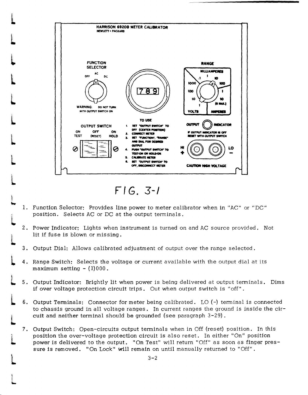
OPERATION AND SERVICE MANUAL
MODEL
METER CALIBRATOR
MANUFACTURING
6920B
CODE
A
-
OPERATING
AND
SERVICE
HEWLETT
PACKARD
MANUAL
HARRISON
DIVISION
Page 2
The
Hewlett-Packard
HEWLETT~PACKARD
CERTIFICATION
Company
certifies
that
this
instrument
was
thoroughly
specifications
Packard
are traceable to
allowedbythe
All
Hewlett-Packard
materials
the
date
in
the
replace
period.
for consequential damages.
tested
Company
WARRANTY
and
ofdelivery, or,inthe
operating
products
No
other
and
inspected
whenitwas shipped from
further certifies
the
U.S.National
Bureau's
workmanship.
manual,
which provetobe
warranty
and
found to
the
that
its
calibration
BureauofStandardstothe
calibration facility.
AND
products
This
caseof
for
the
is expressedorimplied. We
ASSISTANCE
are
warranted
warranty
certain
specified period.
defective
applies for one
major
meet
factory.
against
components
during
its
published
The
Hewlett-
measurements
extent
defects
year
\Ve
will
repair
the
warranty
are
not
in
from
listed
or
liable
For
any
assistance
Service Office..A.ddresses
contact
your
nearest
are
providedatthe
Hewlett-Packard
backofthis
Sales
manual.
and
Page 3
NOTICE
These preliminary instructions
t.!orliest possible deliveryofyour instrument. The Infor-
motionisnotascompleteasthot
In
the finoI yers'on of the manual.
provided to
Servicing Manual for this instrument reaches the proper
person.
supply you with a copy of the complete manual05soon
it becomes oyoilobie.
make
certain
Please moil this
HARRISON
' .....
nwu"~.lCU"
100
LOCUST .....
eNUE•BERKELEY
464-1234
......aCod.
ore
supplied to permit the
which
willbeincluded
The
attached
thot
the final Operating and
cord
immediately
and
LABORATORIES
ISt."
Of
~
v::p
HEIGHTS.
201
•
TWX_2tll.464-2117
NEW
JERSEY
cord
we
is
will
05
onn
o
,
•
o
~
~
.2
.!i
~
o
<
.lI
~
•
o
~
•
i.
.2
Ji
g
8
<
Page 4

BUSINESS
F'II~
elM
'EIlM'T
REPLY
:.;
10·
BEPKI_FY HEIGHTS. N,
Q HARRISON LABORATORIES
Attn. Publications
100 LOCUST
BERKELEY
Dept.
AVENUE
HEIGHTS,
MAIL
H. J.07922
-
J.
-
-
-
-
-
-
-
-
-
-
-
-
-
-
-
-
-
-
-
-
-
-
Page 5
l
L
L
L
L
L
L
l
OPERATION AND SERVICE MANUAL
MODEL
METER CALIBRATOR
MANUFACTURING
6920B
CODE
A
L
L
L
L
L
L
L
L
October,
1:
."iL
1965
L
L
L
Page 6

J
J
J
J
J
J
J
J
J
J
.1
..
J
J
J
J
J
J
~
-
Page 7
l
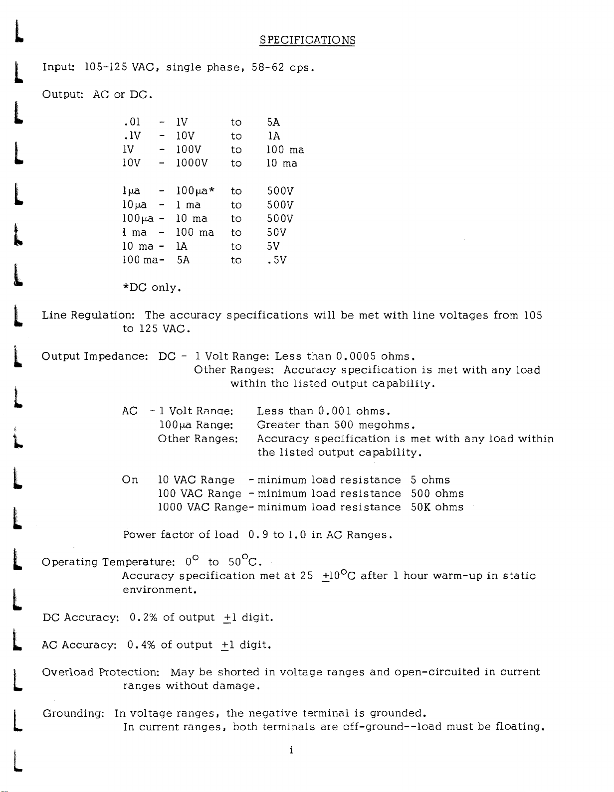
SPECIFICATIONS
L
l
L
L
l
l
L
Input:
Output:
Line
105-125
AC
or
10V
1 rna
10
100
Regulation:
VAC,
DC.
.
01
.1V
IV
IjJ.Ci
10
jJ.Ci
100jJ.Ci
rna -
ma-
*DC
The
to
125
single
IV
-
-
10V
- 100V
-
1000V
-
1001JB*
- 1 rna
-
10
100 rna
-
lA
SA
only.
accuracy
VAC.
rna
phase,
to
to
to
to
to
to
to
to
to
to
specifications
58-62
5A
lA
100 rna
10
500V
500V
500V
50V
5V
.5V
rna
cps.
will
be
met
with
line
voltages
from 105
l
L
L
l
l
l
L
Output
Operating
DC
Accuracy:
AC
Accuracy:
Impedance:
AC
On
Power
Temperature:
Accuracy
environment.
0.2%
0.4%
DC
- 1
100~
Other
10
100
1000
factor
of
of
Volt
VAC
- 1
Volt
Other
Ri'lnqe:
Range:
Ranges:
VAC
VAC
of
0°
specification
output
output
Ranges:
within
Range
Range-minimum
Range-
load
to
50oC.
.::1
.::1
Range:
Less
Greater
Accuracy
the
-
minimum
minimum
0.9
met
digit.
digit.
Less
Accuracy
the
listed
than
listed
to
1.0
at
than
0.0005
specification
output
0.001
than
500
specification
output
load
resistance
load
resistance
load
resistance
in
AC
+lO
o
25
ohms.
capability.
ohms.
megohms.
capability.
Ranges.
C
after1hour
is
is
met
5
ohms
500
50K
met
with
with
any
ohms
ohms
warm-up
any
load
in
load
within
static
L
L
L
Overload
Grounding:
Protection:
ranges
In
voltage
In
current
May
without
ranges,
ranges,
be
shorted
damage.
the
both
in
voltage
negative
terminals
terminal
i
ranges
are
and
is
grounded.
off-ground--load
open-circuited
must
in
be
current
floating.
Page 8

,i
:-"
J
J
J
J
J
J
J
J
J
J
Page 9
L
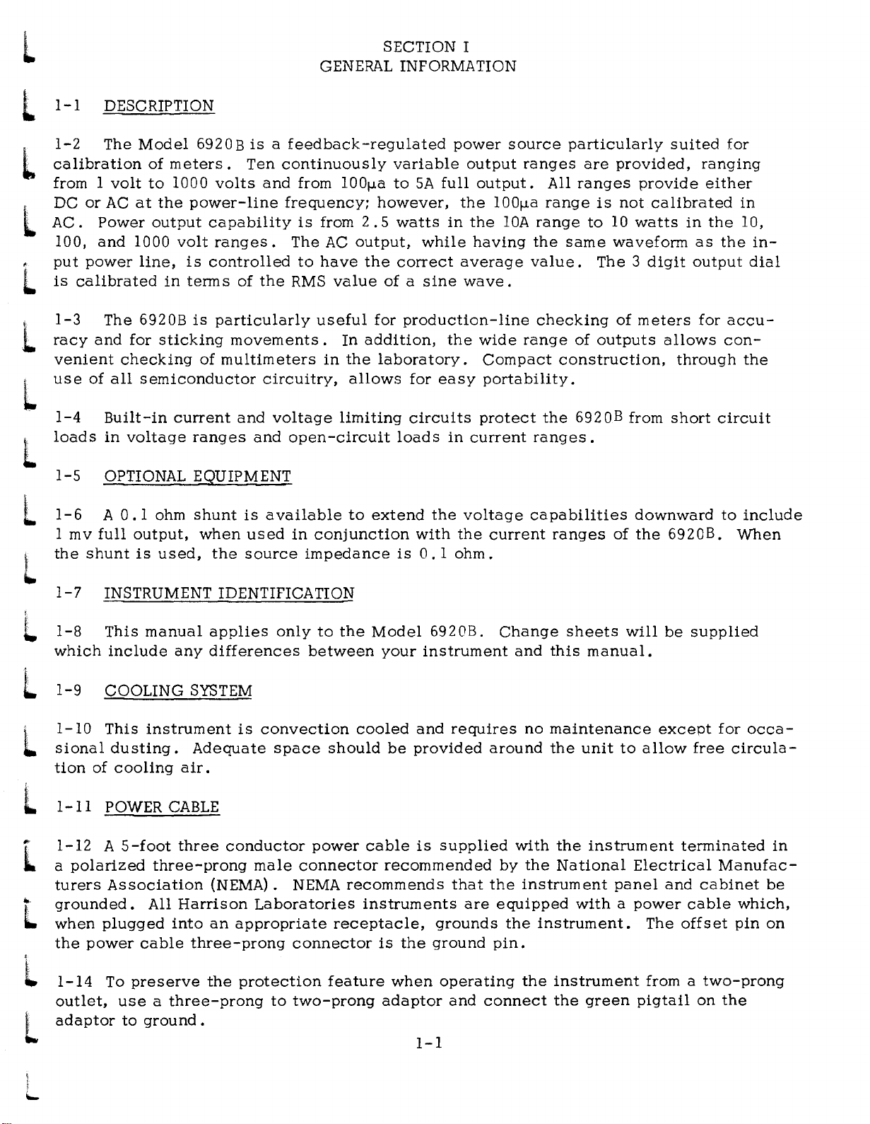
SECTION I
GENERAL INFORMATION
l
calibration
L
from 1
'.
DC
.
AC.
L
put
is
L
....
racy
.
l
venient
l
use
l
loads
L
1-1
1-2
or
100,
power
calibrated
1-3
of
1-4
1-5
1-6
1
mv
the
shunt
DESCRIPTION
The
Model
of
volt
to
AC
at
Power
and
The
and
Built-in
in
OPTIONAL EQUIPMENT
A
full
output
1000
line,
6920B
for
checking
all
semiconductor
voltage
0.1
output,
is
6920Bisa
meters.
1000
the
power-line
volt
is
in
terms
is
sticking
current
ranges
ohm
shunt
used,
Ten
volts
capability
ranges.
controlled
of
particularly
movements.
of
multimeters
and
and
is
when
the
used
source
the
feedback-regulated
continuously
and
from 100J.la
frequency;
is
The
to
RMS
useful
circuitry,
voltage
open-circuit
available
in
conjunction
impedance
from
have
AC
value
In
in
the
allows
limiting
to
2.5
output,
addition,
variable
to
5A
however,
watts
while
the
correct
ofasine
for
production-line
laboratory.
for
circuits
loads
extend
with
is
0.1
full
in
the
easy
in
the
power
output
output.
the
100J.la
the
having
average
wave
wide
Compact
portability.
protect
current
voltage
the
current
ohm.
source
ranges
All
range
lOA
range
the
value.
.
checking
range
the
ranges.
capabilities
particularly
are
provided,
ranges
is
not
to
10
same
construction,
ranges
waveform
The3digit
of
of
outputs
6920B
of
from
suited
provide
calibrated
watts
meters
downward
the
in
as
output
allows
through
short
692GB.
for
ranging
either
the
the
for
accu-
con-
circuit
to
When
in
10,
in-
dial
the
include
L
L
L
L
L
..
L
i
Ii.
L
L
1-7
1-8
which
1-9
1-10
sional
tion
1-11
1-12
a
turers
grounded.
when
the
1-14
outlet,
adaptor
INSTRUMENT IDENTIFICATION
This
include
COOLING
This
dusting.
of
POWER
A
polarized
Association
plugged
power
To
manual
instrument
cooling
5-foot
three-prong
All
cable
preserve
useathree-prong
to
ground.
applies
any
differences
SYSTEM
Adequate
air.
CABLE
three
Harrison
into
conductor
(NEMA). NEMA
an
three-prong
the
only
is
convection
space
male
Laboratories
appropriate
protection
connector
connector
to
two-prong
to
the
between
cooled
should
power
recommends
receptacle,
feature
Model
your
cable
recommended
instruments
is
adaptor
be
the
when
and
provided
is
1-1
692
instrument
ground
OB.
requires
supplied
that
are
grounds
operating
and
connect
Change
and
no
around
with
by
the
the
instrument
equipped
the
pin.
the
sheets
this
manual.
maintenance
the
unit
the
instrument
National
withapower
instrument.
instrument
the
green
will
to
allow
Electrical
panel
The
from a
pigtail
be
supplied
except
free
terminated
and
cabinet
cable
offset
on
for
occa-
circula-
Manufac-
which,
pin
two-prong
the
in
be
on
Page 10
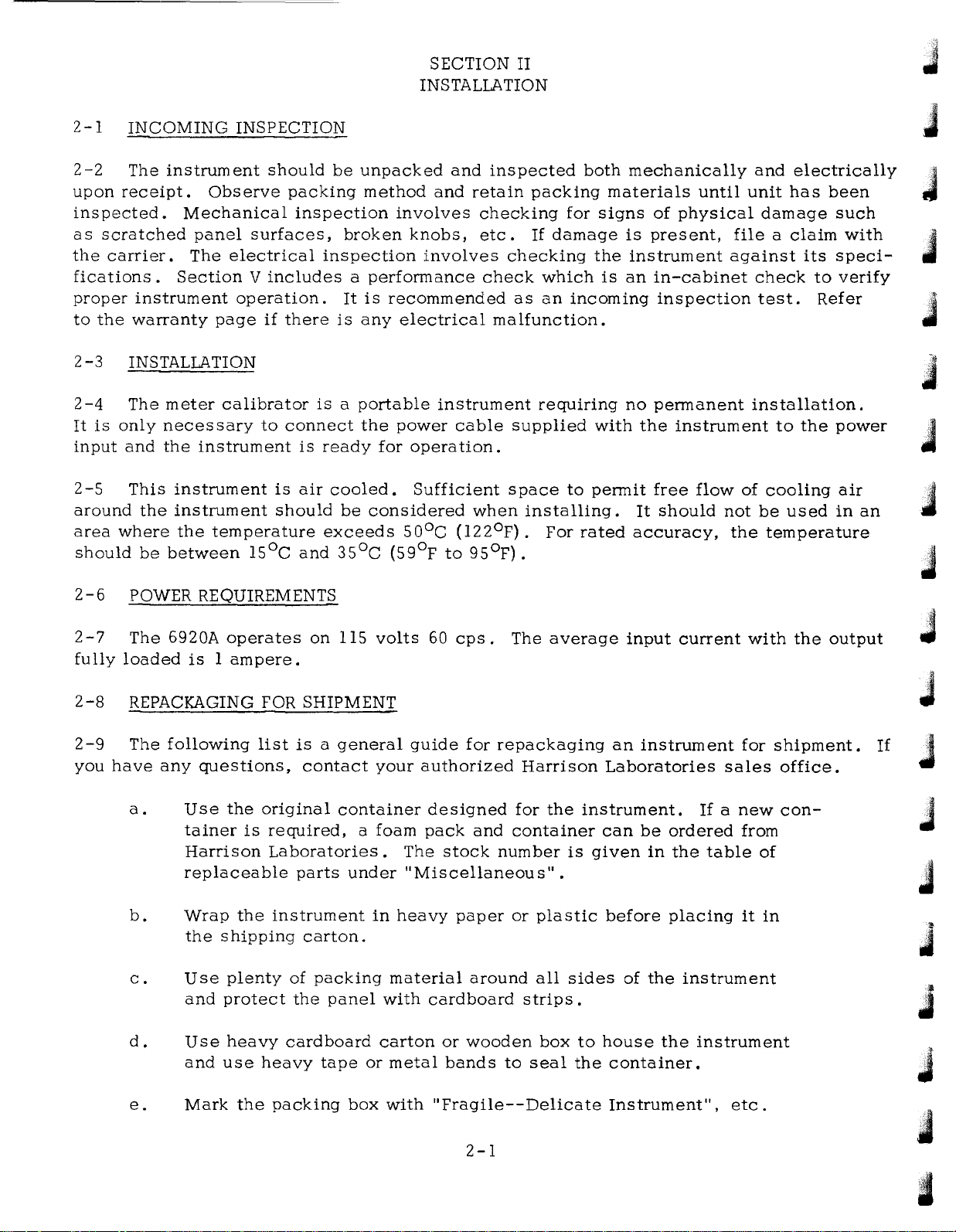
SECTION II
INSTALLATION
J
2-1
2-2
upon
inspected.
as
the
fications.
proper
to
2
2-4
It
input
2
around
area
should
2-6
INCOMING
The
receipt.
scratched
carrier.
instrument
the
warranty
-3
INSTALLATION
The
is
only
and
-5
This
the
where
be
POWER REQUIREMENTS
instrument
Observe
Mechanical
panel
The
electrical
Section
page
meter
necessary
the
instrument
instrument
between
calibrator
instrument
the
temperature
INSPECTION
should
surfaces,
V
includes
operation.
if
there
to
connect
is
should
ISoC
be
packing
inspection
inspection
isaportable
is
ready
air
cooled.
exceeds
and
unpacked
method
involves
broken
a
It
is
any
the
be
350C (590F
knobs,
involves
performance
is
recommended
electrical
power
for
operation.
Sufficient
considered
SOoC
and
inspected
and
retain
checking
etc.
check
malfunction.
instrument
cable
when
(l220F).
to
9SoF).
packing
If
damage
checking
which
as
an
requiring
supplied
space
installing.
For
both
materials
for
signs
the
is
incoming
with
to
permit
rated
mechanically
until
of
physical
is
present,
instrument
an
in-cabinet
inspection
no
permanent
the
instrument
free
flow
It
should
accuracy,
and
electrically
unit
has
damage
fileaclaim
against
check
test.
installation.
to
the
of
cooling
not
be
used
the
temperature
its
to
Refer
been
such
with
speci-
verify
power
air
in
J
J
J
J
J,
J
an
J
2-7
fully
2-8
2
-9
you
The
6920A
loaded
REPACKAGING FOR SHIPMENT
The
following
have
any
a.
b.
c.
d.
operates
is1ampere.
list
questions,
Use
the
original
tainer
Harrison
replaceable
Wrap
the
Use
and
Use
and
is
the
shipping
plenty
protect
heavy
use
heavy
on
115
isageneral
contact
container designed
required,
Laboratories.
parts
instrument
of
the
cardboard
under
carton.
packing
panel
tape
volts
guide
your
authorized
a
foam
in
or
pack
The
"Miscellaneous"
heavy
material
with
cardboard
carton
metal
60
stock
or
bands
cps.
for
and
paper
around
wooden
The
average
repackaging
Harrison
for
the
container
number
or
to
plastic
all
strips.
box
seal
is
.
sides
to
the
input
an
instrument
Laboratories
instrument.
can
be
given
in
before
of
the
house
container.
current
If
ordered
the
table
placing
instrument
the
instrument
for
sales
a
new
from
it
with
shipment.
office.
con-
of
in
the
output
J
J
If
J
J
J
J
J
J
e.
Mark
the
packing
box
with
"Fragile--
2-1
Delicate
Instrument",
etc.
;,1
II
Page 11

L
l
L
l
L
L
L
NOTE:
for
owner
any
number
If
service
and
correspondence,
and
the
instrument
or
repair,
indicating
serial
attach
the
be
number.
is
to
a
service
sure
be
tag
to
identify
shipped
to
the
or
repair
to
Harrison
instrument
to
be
accomplished.
the
instrument
Laboratories
identifying
by
model
the
In
L
L
L
L
L
l
l
L
I
..
L
2-2
Page 12
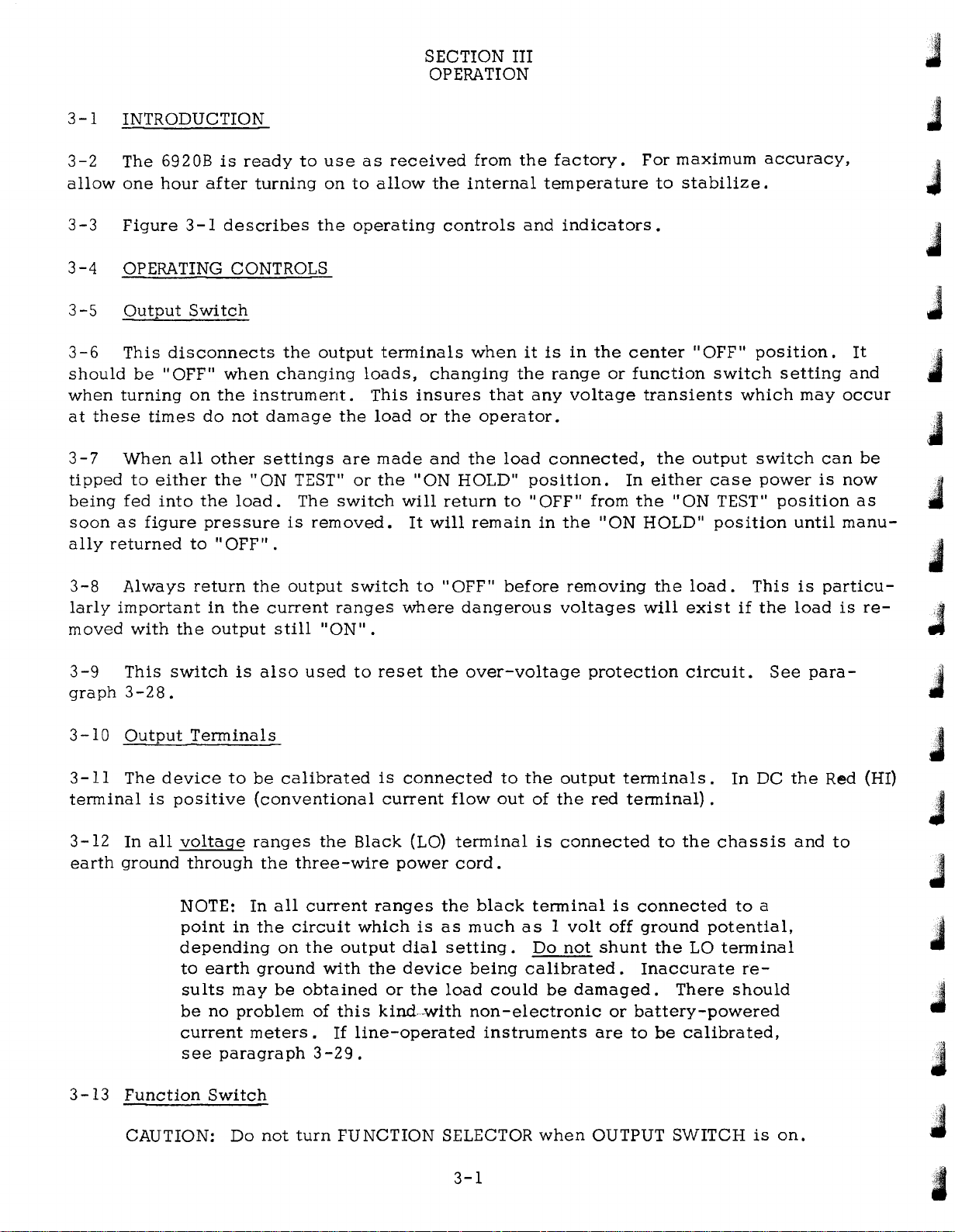
SECTION
OPERATION
3
-1
INTRODUCTION
III
J
J
3-2
allow
3-3
3
-4
3-5
3-6
should
when
at
these
3
-7
tipped
being
soon
ally
3-8
larly
moved
The
6920B
one
hour
Figure
OPERATING CONTROLS
Output
This
disconnects
be
"OFF"
turning
times
When
to
either
fed
into
as
figure
returned
Always
important
with
after
3-1
Switch
on
do
all
the
pressure
to
return
the
is
ready
turning
describes
when
the
instrument.
not
other
the"
load.
"OFF"
the
in
the
output
the
changing
damage
settings
ON TEST"
is
.
output
current
still
to
use
on
the
output
the
are
The
switch
removed.
ranges
"ON".
as
received
to
allow
operating
terminals
loads,
This
load
made
or
the"
will
It
switch
where
from
the
internal
controls
when
changing
insures
or
the
operator.
and
the
ON HOLD"
return
will
remain
to
"OFF"
dangerous
that
load
to
before
the
factory.
temperature
and
indicators.
it
is
in
the
range
any
voltage
connected,
position.
"OFF"
in
the
removing
voltages
the
or
from
"ON
For
to
center
function
transients
the
In
either
the"
HOLD"
the
will
maximum
stabilize.
"OFF"
switch
which
output
case
ON TEST"
position
load.
exist
if
accuracy,
position.
setting
may
switch
power
position
until
This
is
the
load
It
and
occur
can
be
is
now
as
manu-
particu-
is
re-
J
J
J
J
J
J
3-9
graph
3-10
3-11
terminal
3-12
earth
3
ground
-13
This
switch
3-28.
Output
The
device
is
positive
In
all
voltage
NOTE:
point
depending
to
be
current
Function
is
also
Terminals
to
be
(conventional
ranges
through
earth
sults
no
see
Switch
the
In
in
the
ground
may
problem
meters.
paragraph3-29.
used
calibrated
the
three-wire
all
current
circuit
on
the
with
be
obtained
of
to
reset
is
connected
current
Black
power
ranges
which
output
this
If
line-operated
dial
the
device
or
kinctwith
the
(LO)
is
the
over-voltage
to
flow
out
terminal
cord.
the
black
as
much
setting.
being
load
could
non-electronic
instruments
protection
the
output
of
the
is
connected
terminal
asIvolt
Do
not
calibrated.
be
damaged.
terminals.
red
terminal)
to
is
connected
off
ground
shunt
are
the
Inaccurate
or
battery-powered
to
be
circuit.
In
.
the
chassis
to
potential,
LO
terminal
There
calibrated,
should
re-
DC
a
See
para-
the
and
J
J
Red (HI)
J
to
J
J
J
J
CAUTION:
Do
not
turn
FUNCTION
SELECTOR
3-1
when
OUTPUT
SWITCHison.
J
~
Page 13
L
l
HARRISON
HEWU:TT•P'ACKAIID
69208
M£TER CALIBRATOR
L
l
L
L
L
L
l
,
....
1:
1
·
Function
position.
WARNING:
WITH
OUTPUT SWITCH
ON
TEST ("ESET) HOLD
Selector:
Selects
FUNCTION
SELECTOR
AC
OFF
o
DO~TTUllN
OUTI'UT
SWITCH
OFF
Provides
AC
or
DC
ON
DC
ON
FIG.
line
at
the
I.
sn
"ClVI'PUT
OfF
fc:unn
,.
e:a-rr
3. lET
'?UIIIC11ON"
MIl
IlIA&.
0lmVf
4. PUIN
Tb't-Glt
I.
~TI
I.
lET
"'OUTPUT
OfF. lIlICXIIlNI:Cf
power
output
roUSE
.,..
fOIl
"ClUI1'Uf
OIlllDl.lH*
__
3-1
to
IWlTCW
TO
"OII11llM1
......
......
IWII'Qr"
TO
swrfQl"
TO
.,..
meter
terminals.
VOLTS
OUTPUT
•
0lmVf
-.r
calibrator
RANGE
1
0
IlllllCAlOlt•
WITII
0IITPIIf
when
IMlICATOit
OfF
swm:M
in
"AC"
or
"DC"
l
L
l
L
L
L
l
L
2
3
4
5.
6.
7.
·
·
·
Power
litiffuse
Output
Range
maximum
Output
if
Output
to
cuit
Output
position
power
sure
Indicator:
Switch:
over
chassis
and
is
is
Dial:
Indicator:
voltage
Terminals:
Switch:
is
blown
Allows
setting
ground
neither
the
over-voltage
delivered
removed.
Lights
Selects
- (1)a00 .
Brightly
protection
Connector
in
terminal
Open-circuits
to
"On
when
or
missing.
calibrated
the
all
voltage
the
Lock"
instrument
adjustment
voltage
lit
when
circuit
for
should
output
protection
output.
Will
or
power
trips.
meter
ranges.
be
grounded
circuit
"On
remain
is
turned
of
current
is
Out
being
In
terminals
is
Test"
on
3-2
on
output
available
being
when
calibrated.
current
(see
will
until
delivered
output
paragraph
when
also
return"
manually
and
over
with
ranges
in
reset.
AC
the
switch
La
Off
Off"
source
range
the
output
at
output
is
(-)
terminal
the
ground
3-29)
(reset)
In
either
as
returned
provided.
selected.
"off".
.
position.
"On"
soon
to
dial
at
terminals.
is
connected
is
inside
position
as
finger
"Off"
.
In
its
Not
Dims
the
this
pres-
cir-
L
Page 14
3
-14
The
position,
put
terminals,
3-15
Range
Function
input
power
while
Switch
Switch
is
in
"DC",
off.
is
the
input
In
"AC",alternating
direct
line
current
switch
is
available.
for
the
current
meter
will
calibrator.
be
delivered
In
the11OFF
to
the
out-
11
J
J
3-16
tested.
clockwise,
3-17
3-18
output
3-19
immediately
setting.
3-20
3-21
the
also
will
3
the
bilities
The
The
OutEut
The
within
To
determine
For
Output
The
output
will
be
occurifthe
-22
If
the
"OFF (RESET)"
of
range
three-digit,
output
terminals.
the
switch
range
to
(1)
Dial
any
to
the
example:
Indicator
off
output
6920B.
000.
range.
indicator
load
selects
indicated
ten
the
correct
left
of
123
The
dim
is
removed
light
position.
is
then
turn
the
on
is
light
when
not
return
the
by
the
output
decimal
left-hand
the
lit
is
outifthe
the
in
on
and
Check
the
current
switch
dial
point
digit,
lOrna
range
when
over-voltage
any
of
output
the
load
output
or
voltage
is
the
allows
placement,
then
is
the
output
the
current
power
to
be
switch
range
output
continuous
multiply
.123
meter
protection
sure
available
x lOrna =
calibrator
switch
ranges.
is
desired,
that
to
"ON".
consider
appropriate
adjustment
the
this
number
1.
is
in
the
circuit
move
it
is
within
with
decimal
23ma.
is
delivering
"OFF"
is
the
to
the
meter
the
output
of
the
point
by
the
position.
activated,
output
the
voltage
being
dial
calibrator
to
range
switch
switch
power
It
which
capa-
J
fully
J
J
be
to
to
J
3-23
3-24
panel,
3-25
3-26
is
proaching
in
GENERAL OPERATING PROCEDURE
A
Overload
The
being
the
various
brief
is
used.
procedure
also
load
zero
shown
should
If
excessive
for
large
ranges.
for
in
figure
be
within
overloads.
using
current
the
3-1.
the
Model
current
is
drawn
Table
692GB
capability
the
3-1list5
3-3
meter
output
the
calibrator,
of
the
voltage
output
voltage
will
capabilities
printed
range
begin
on
with
to
of
the
fall,
the
front
which
ap-
6920B
J
J
it
Page 15
L
TABLE
3-1
l
l
L
L
l
L
L
L
anqe
I
volt
DC
10
volts
lOa
volts
1000
volts
100fJ.a
lma
lOrna DC
100ma
I
10
I
10
100
1000
100fJ.a AC
Ima
lOrna
100ma
I
10
DC
DC
DC
ampere
amperes
volt
AC 5
volts
volts
volts
AC
AC
AC
ampere
amperes
DC I
DC
DC
DC
DC
AC
AC
AC
AC 5
AC
aXlmum
5
amperes
ampere
100ma
lama
500
volts
500
volts
500
volts
50
volts
volts
5
amperes/a.
5
amperes
I
ampere
100ma
lama
Not
Calibrated
500
volts
500
volts
50
volts
volts
5
amperes/a.
u:put
o tMR
5
5
volts
volts
M
eter
R
---
---
---
---
---
---
---
---
---
---
---
5
ohms
500
ohms
5OKohms
---
---
---
---
---
---
eSlstance
minimum
minimum
minimum
l
l
l
L
l
l
L
L
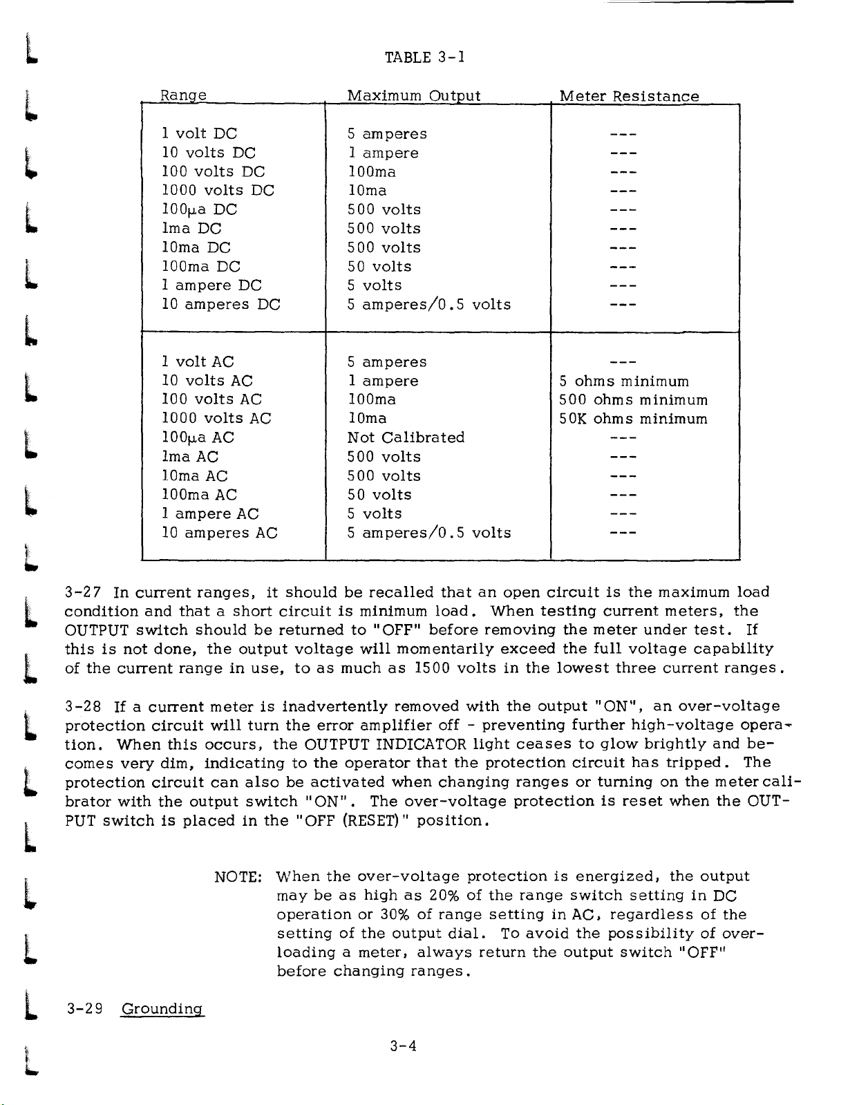
3-27
condition
OUTPUT
this
of
3-28
protection
tion.
comes
protection
bratorwith
PUT
is
the
switch
In
not
current
If
a
When
very
current
and
switch
done,
current
circuit
this
dim,
circuit
the
is
ranges,
thatashort
should
the
range
meter
will
occurs,
indicating
can
output
placed
output
in
turn
also
switch"
in
NOTE:
be
use,
it
should
circuit
returned
voltage
to
as
is
inadvertently
the
error
the
OUTPUT INDICATOR
to
the
be
activated
ON".
the"
OFF (RESET)"
When
may
be
operation
setting
loading
before
be
recalled
is
minimum
to
"OFF"
will
much
amplifier
operator
The
the
over-voltage
as
high
or
of
the
a
meter,
changing
that
load.
before
momentarily
as
1500
removed
off-preventing
that
when
30%
output
changing
over-voltage
position.
as
20%
of
range
always
ranges.
an
removing
volts
with
light
the
protection
protection
of
the
dial.
return
open
When
exceed
in
the
the
ceases
ranges
protection
range
setting
To
avoid
circuit
testing
lowest
output
is
in
the
is
current
the
meter
the
full
"ON",
further
to
glow
circuit
or
turning
is
energized,
switch
AC.
the
possibility
output
the
maximum
meters,
under
voltage
three
high
brightly
has
reset
setting
regardless
switch..OFF"
test.
capability
current
an
over-voltage
-voltage
tripped.
on
the
when
the
in
the
ranges.
and
meter
the
output
DC
of
the
of
over-
load
If
opera·
be-
The
cali-
OUT-
L
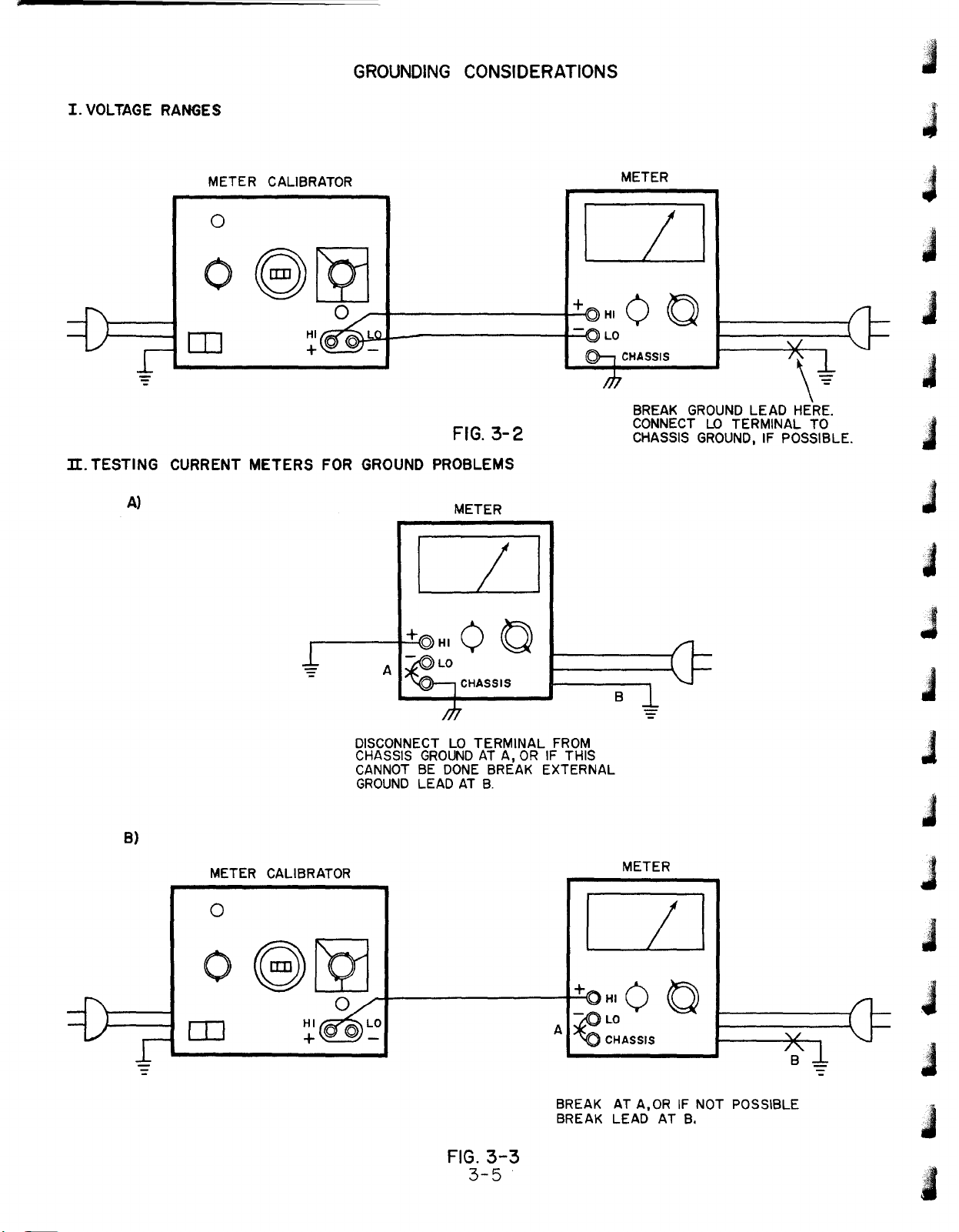
3-29
Grounding
3-4
Page 16
GROUNDING
CONSIDERATIONS
I.VOLTAGE
1I.
TESTING
A)
RANGES
METER CALIBRATOR
o
o
OJ
CURRENT
METERS
HI
+
FOR
GROUND
FIG.
3-2
PROBLEMS
METER
METER
LI
CHASSIS
BREAK
CONNECT
CHASSIS
GROUND
LO
GROUND,
LEAD HERE.
TERMINAL
IF POSSIBLE.
\~
TO
B)
METER CALIBRATOR
0
0
eLQ]
[I]
HI
+
A
DISCONNECT
CHASSIS
CANNOT
GROUND
....-I------+_"""-{+(]
0
©~
/
I
00
CHASSIS
LO
GROUNDATA,ORIF THIS
BE
LEADATB.
TERMINAL
DONE
BREAK EXTERNAL
FROM
A
~~~ASSIS
B
METER
II
HI 0 0
-
FIG.
3-5
BREAK
BREAK LEAD AT
3-3
AT
A,ORIFNOT POSSIBLE
B.
Page 17
l
l
l
L
L
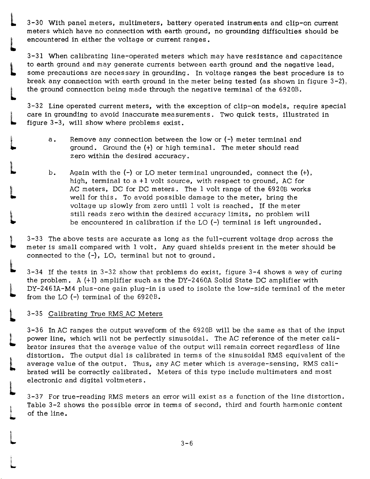
3-30
meters
encountered
3-31
to
some
break
the
3-32
care
figure
With
which
When
earth
precautions
any
ground
Line
in
grounding
3-3,
ground
panel
calibrating
connection
connection
operated
will
have
in
meters,
either
and
are
to
show
no
connection
the
line-operated
may
generate
neces
with
being
current
avoid
where
multimeters,
with
voltage
sary
earth
meters,
inaccurate
or
currents
in
grounding.
ground
made
problems
through
battery
earth
current
meters
with
measurements.
exist.
between
in
the
the
the
ground,
ranges.
which
meter
negative
exception
operated
no
may
earth
In
voltage
being
instruments
grounding
have
ground
ranges
tested
terminal
of
clip-on
Two
quick
and
difficulties
resistance
and
the
the
(as
of
the
models,
tests,
clip-on
and
negative
best
shown
6920B.
illustrated
current
should
capacitance
lead,
procedure
in
figure
require
be
is
to
3-2),
special
in
L
L
l
l
3-33
L
meter
connected
l
3-34
the
DY-2461A-M4
L
from
l
3-35
a.
b.
The
is
small
If
the
problem.
the
LO
Calibrating
Remove
ground.
zero
Again
high,
AC
well
voltage
still
be
above
to
the
tests
A (+1)
(-)
plus-one
any
Ground
within
with
the
terminal
meters,
for
this.
up
slowly
reads
encountered
tests
compared
(-),
in
terminal
True
zero
are
La,
3-32
amplifier
RMS
connection
the
(+)
the
desired
(-)
or
to
a + 1
DC
for
DC
To
avoid
from
within
in
calibration
accurate
with1volt.
terminal
show
gain
of
plug-in
the
AC
that
such
6920B.
Meters
between
or
accuracy.
La
meter
volt
meters.
possible
zero
the
as
but
problems
as
is
the
high
terminal.
terminal
source,
TheIvolt
until1volt
desired
if
the
long
as
Any
guard
not
to
the
DY-2460A
used
to
low
with
damage
accuracy
LO
the
full-current
shields
ground.
do
exist,
isolate
or
(-)
meter
The
meter
ungrounded,
respect
range
to
is
reached.
(-)
terminal
Solid
the
the
limits,
present
figure
State
low-side
to
meter,
ground,
of
the
no
is
voltage
3-4
DC
terminal
should
connect
6920B
bring
If
the
problem
left
in
the
shows
amplifier
terminal
and
read
the
(+),
AC
for
works
the
meter
will
ungrounded.
drop
across
meter
a
should
way
with
of
of
the
the
be
curing
meter
l
L
L
L
3-36
power
brator
distortion.
average
brated
electronic
3-37
Table
of
the
In
line,
insures
will
For
3-2
line.
AC
ranges
which
that
The
output
value
of
be
correctly
and
digital
true-reading
shows
the
will
the
the
the
output
not
be
average
dial
is
output.
calibrated.
voltmeters.
RMS
meters
possible
waveform
perfectly
value
calibrated
Thus,
error
any
an
in
of
sinusoidal.
of
the
in
AC
Meters
error
terms
the
output
terms
meter
of
will
of
3-6
6920B
will
of
which
this
exist
second,
will
be
The
AC
remain
the
sinusoidal
is
average-sensing,
type
include
asafunction
third
the
same
reference
correct
multimeters
and
fourth
as
of
regardless
RMS
of
the
harmonic
that
of
the
meter
equivalent
RMS
and
line
distortion.
the
input
cali-
of
line
of
cali-
most
content
the
Page 18

METER
CALIBRATOR
J
J
J
J
METER
0
/
0
CD
-
8CQJ
0
A
I
©
-
J
~
'J
J
J
BREAK
DY2460A
GROUNDATA
OR
B
J
J
J
ELIMINATING
WITH
FIG.
3-4
GROUND
+1
AMPLIFIER
3-7
J
J
J
:t
II
PROBLEMS
j
J
J
Page 19

L
TABLE
3-2
L
l
l
L
L
L
L
L
3-38
capable
to
the
terminal
AC
source
If
AC
greater
of
HARMONIC
1%
2%
5%
10%
20%
1%
2%
5%
10%
supplying
reference
2
of
Transformer
to
the
%
0
Second
Second
Second
Second
Second
Third
Third
Third
Third
accuracy
regulator.
points
OUTPUT
LINE WAVEFORM DISTORTION
is
needed
60
cps,
shown,
15
To
TI.
ERROR
AVERAGE-SENSING
RMS
CALIBRATED METER
for
volts
the
do
Connect
low
± 10%
this,
%
true
side
DUE TO
ERROR
0
0
0
0
0
0
0
0
0
0
RMS
at
refer
a
going
meters,
2ma,
to
figure
pair
to
can
of
shielded
Aland
%
ERROR
TRUE RMS METER
0
-0%
to
+0.02%
-0%
to
+0.02%
-0%
to
+0.
-0%
to
+0.50%
-0.07%
-0.65%
-0.65%
-1.54%
-3.14%
an
external
be
used
3-5.
the
to
supply
Hisconnect
leads
high
side
to
to
to
to
to
sine
from
12%
+1.98%
+0.69%
+0.69%
+1.79%
+3.53%
wave
the
the
the
going
oscillator
signal
lead
at
IS
volt
to
A2.
l
L
L
l
l
L
L
3-39
3-40
AC
reference
changes
in
the
output,
used
3-5
for
Effects
In
order
in
line
AC
output.
an
external
to
replace
instructions
NOTE:
AC
being
of
Rapid
to
feedback
voltage
the
The
calibrator
present
Line
Voltage
prevent
Ifaparticularly
oscillator
line-derived
on
distortion
loop
will
this
has
procedure.
as
not
capable
should
damage
Changes
of
been
made
be
immediately
noisy
AC
input
never
to
the
AC
line
of
supplying
be
the
inverter
waveform
slow
corrected,
is
normally
operated
compared
causing
60
cps,
used.
without
may
result.
in
the
with
producing
excessive
15
See
AC
reference
60
cps.
instability
volt
± 10%
paragraph
the
15
a
momentary
volt
circuit,
Hence,
at
2ma,
3-38
of
and
the
sudden
shift
the
AC
can
figure
be
L
3-8
Page 20

ru;I
a..
u
o
U)
I
en
~
0<[
>~
I~
!\I,
J
J
J
J
J
J
a:::
o
I-
<[
a:::
m
5
a:::
l.LI
I-
l.LI
~
a::lLJ
°u
~z
lLJ
...J
...Ja::
-lLJ
UlL.
C/)
lLJ
LOO
I
a::
l"')...J
u
««
.Z
(!)a::
lLJ
lL.lLJ~
~«
x
a::
lLJlLJ
lL.Q..
00
~g
::::>
J
J
J
J
j
J
J
J
3-9
J
J
J
J
j
Page 21

L
I
1..
,
'-
'
.
t
4-1
4-2
bration
regulator
dary
output
INTRODUCTION
The 6920 Bisa
windings
of
voltage
transistor.
is
rectified
and
provide
and
PRINCIPLES OF OPERATION
multiple-range
current
This
current
filtered
meters.
provides
up
and
SECTION IV
AclDC
An
AC
which
to5amps
supplied
power
inverter
is
and
voltage
to
the
supply
circuit
fed
toatransformer.
output
which
is
to
1000
terminals.
used
is
suitable
following
volts.
The
The
for
the
A DC
various
square
cali-
series
seconwave
4-3
set
L
amplified
L
4-4
rectifiers
·"..
modulator,
negative
L
4-5
and
l
indicator
4-6
l
4-7
is
t
voltage
t
current
..
range.
back
L
means
A
closed-loop
by
the
AC
Auxiliary
an
amplifier
BLOCK
Figure
sampled
ranges
ranges
The
to
the
of
output
and
operates
operation
are
bypassed
in
the
feedback
circuits
lamp
the
is
DIAGRAM
4-1
by
the
this
it
range
input
output
feedback
dial,
error
to
used
shows
isaseries
amplifier
withasuitable
the
is
similar
at
amplifier,
during
include
maintain
to
an
range
resistor
divider
isavoltage
which
system
series
the
both
the
show
over-all
monitoring
configurations
where
operates
regulator
with
the
secondary
keyed
halves
a
protective
inverter
the
state
to
obtainasignal
divider,
it
controls
measure
exception
of
the
block
resistor;
is
compared
R4.
the
of
transistor.
that
of
the
output
at
the
inverter
inverter
current
transformer
of
the
over-voltage
diagram
for
example
for
are
shown
withavariable
output
the
output.
an
transformer
frequency
cycle.
limit,
inastate
of
the
which
1000:1
example,
in
figure
by
comparing
AC
reference
an
over-voltage
trip.
Model
is1volt
in
1000
4-2.
a
reference
The
voltage
is
andasynchronous
is
used
of
DC
balance.
6920B.
for
full
the
1000
ohms
This
reference
difference
used.
to
trip
The
output.
volt
in
signal
voltage,
The
maintain
circuit,
An
output
range.
the
Ima
is
fed
voltage,
is
de-
output
signal
In
the
In
set
by
4-8
DC
L
In
:
4-9
..
further
L
4-10
4-11
Q14
L
operation
transformer.
~
i.r
4-12
all
L
full-wave
sine
l
The
output
this
demodulator
AC,
the
demodulator
The
demodulator
amplified
INVERTER
The
output
and
Q15,
this
In
AC,
synchronized
rectified
wave
is
of
and
of
which
produces
because
with
obtained
the
error
is
bypassed,
reverses
feeds
used
the
is
sinusoidal
series
driven
a
the
the
on
to
square
AC
AC
the
amplifier
the
a
signal
controlaseries
regulator
synchronously
wave
reference,
power
waveform.
transformer
is
its
function
amplifier
to
signal
line,
delivered
the
is
the
primary.
being
polarity
power
regulator
applied
with
which
synchronous
the
signal
After
passing
4-1
to
the
taken
whenever
regulator.
power
to
an
inverter
the
AC
is
suitable
applied
through
synchronous
by
the
output
the
Here
amplifier.
consisting
power
demodulator
to
line.
for
the
the
inverter
demodulator.
power
inverter
the
error
In
the
applying
and
the
inverter
rectifiers.
switches.
signal
of
transistors
DC
to
the
inverter
appears
the
desired
is
mode
output
as
In
of
are
a
Page 22

AC
~
LINE
- , I DRIVE I > I I I I
INVERTER
IOV t
rl.JLS
~
I~
I~
f
....-
C/)
0::
w
LL
~
U
W
0::
t--
r--
I---
r--
(Iv
SIGNAL FOR]
l!ULL
~
>--
:x:
U
~
~
C/)
z
0
~
U
Z
:J
LL
--
OUTPUTJ
r----"
:x:~
uw
~C/)
r--
i(!)
C/)z
wo
(!)z
z-
I--
et~
o::~
t----
-
0::
0
~
U
i[
~
:J
0
--
~
r-",
1'-...,._,
1
I
I
I
-
0::
0
:x:!i
U:J
~z
-w
~~
C/)~
wet
(!)
z~
et
u
Il::et
m
0
w
w
LL
--
.roo
+
~
~
:J
a.
~
:J
o
."If
aSll:
,
L'
---------:1==,-0
1-
'\itta
aw.
'--
IOFFII~
o TRANSFORMER
mJL.o
DC
.'~
.....
CURRENT
LIMIT
DC
BALANCE I
AMPLIFIER
I < I
~
4!:
FIG.4-1
FUNCTIONAL BLOCK
'Iii.
&w
••
'
DIAGRAM
.,fli
a
'v.
I,h
"gil
hiii
//1
"!Iilt
atlt:i'..,
a..6Jii,
.oiili.
Page 23

L
L
I
VOLT
10
VOLT
100
VOLT
1000 VOLT
L
l
L
l
l
l
L
TO
ERROR
AMPLIFIER
5
MEG
TO
ERROR
AMPLIFIER
100).10
+
+
4.5K
TO
E.A.
500
TO E.A.
K
Ima
49.5K
+
+
500
TO
TO
E.A.
50K
E.A.
lOrna
499.5K
+
500
+
TO
E.A.
TO E.A.
100
500
+
rna
+
l
L
L
L
l
L
L
l
10K
TO
ERROR
AMPLIFIER
1
lAMP
5
+
IK
TO E.A.
,In
10AMP
100
+
10
L
RANGE
FIG.
4-2
RESISTOR CONFIGURATION
4-3
Page 24

4-13
OUTPUT TRANSFORMER
J
4-14
levels
to
4-15
4-16
AC
reference,
equalizers.
4-17
4-18
voltage
current
4-2the
4-19
4-20
Circuitry
input
low-level
The
which
1000Vat
FUNCTION
This
mode
RANGE
The
ranges,
DC REFERENCE
A
line.
output
switch
of
bypas
range
or
current
range
6.2
is
error
transformer
are
associated
lOrna,
SWITCH
selects
operation
ses
SWITCH
switch
range.
to
resistor
volt
temperature
used
The
to
reference
amplifiers.
100Vat
the
the
synchronous
selects
provide
configuration
minimize
changes
with
100ma,
whether
output
In
the1volt/full-output
circuit
rectifiers
the
addition,
compensated
the
the
its
four
10Vat
the
transformer
demodulator
output
it
selects
for
each
current
also
changes
supplies+12.6
power
secondary
lA
on
and
are
bypassed.
windings
of
the
reference
its
windings;
2V
at
output
in
DC
appropriate
the
proper
sample
ten
diode
through
volts
primary
.SA.
is
to
It
and
of
the
ranges
is
this
to
these
be
also
changes
to
divider
output
is
used
diode
and
-9.4
one
of
levels
rectified
selects
the
the
selected
or
series
signal.
shown.
as
the
with
volts
four
correspond
or
the
feedback
DC
changes
to
impedance
not.
AC
resistor,
reference.
operate
or
output
In
figure
In
DC
loop
in
the
the
the
J
J
J
J
J
in
j
J
J
4-21
AC
REFERENCE
~--~------
DC
REFERENCE
+62V
CR31
CR30
R67
R66
R65
----~---------~-------------
R68
UNREGULATED
Al
R76
R4>+----O
AC
PHOTORESISTOR
IV
AC
REFERENCE
VOLTAGE
J
j
J
J
J
J
J
j
FIG.
4-3
AC REFERENCE
4-4
J
:i
•
Page 25

i
..
\.
ill
4-22
line
ately
the
error
to
restore
in
figure
The
and
controlling
converted
DC
reference.
and
AC
drives
the
4-3.
reference
its
to
DC,
A
an
incandescent
AC
reference
voltage
amplitude
proportional
DC
amplifier
to
is
obtained
withaphoto-resistor.
to
consisting
lamp
the
desired
the
which
value.
by
average
taking
of
transistors
affects
A
an
AC.
the
block
AC
signal
The
AC
so
This
signal
Q1,
Q3
photo-resistor
diagram
of
derived
obtained
is
compared
and
in
this
from
the
is
Q5
amplifies
suchaway
circuit
AC
accur-
with
appears
I
the
as
4-23
ing
L
advantage
on
4-24
4-25
L
transformer
unbalance
the
suchaway
with
the
L
L
L
,
...
AC
diodes
the
accuracy
BALANCE
An
primary
respect
AC
reference
to
DC
CR30
that
changes
AMPLIFIER
amplifier
primary
exists,
current.
as
to
to
the
conversion
and
CR31
in
of
the
AC
consisting
by
means
the
amplifier
In
the
make
signal
the
other.
which
is
accomplished
which
diode
to
"ON"
In
DC
of
of
DC
AC,
has
resistance
conversion
Q30
resistors
output
mode
drive
time
the
the
its
and
is
of
operation
of
one
balance
effect
by
feedback
with
proces
Q31
is
R46
and
used
of
amplifier
of
an
AC-coupled
network.
voltage
s .
connected
R47
to
make
the
the
two
balancing
and
to
as
shown
correction
timing
inverter
output
the
feedback
This
configuration
temperature
sense
of
changes
transformer
R46
R47
the
in
figure4-4.
in
the
the
inverter
transistors
amplifier
have
average
circuit
is
slightly
the
DC
DC.
contain-
has
little
DC
If
a
DC
to
balance
changed
longer
level
the
effect
in
the
in
of
•
L
L
L
L
l
L
....
TO
INVERTER
DRIVE
....
-----
CIRCUIT
-----
TO REFERENCE
o
IOFFJ
'----{)
[££]
[]I]
mJ
......
0
_-----~,r
o
IOFF(
o
[IT]
......
0
------~
INPUT
....
TRANSFORMER
Rl00
C27
Rl0l
FIG.
4-4
DC
BALANCE AMPLIFIER
4-5
Page 26

4-26
INVERTER
4-27
apply
primary.
4-28
4-29
verter
R87
Transistors
transistors.
l
The
the
output
This
INVERTER
A
signal
driver.
and
C25
inverter
allows
obtained
This
and
026
consists
of
the
DRIVER
signal
R89
and
and
027
of
transistors
series
use
from
regulator
ofatransformer
the
is
applied
C26
make
drive
transistors
AC
alternately
line
at
the
transition
is
the
014
to
used
bases
028
and
step
and
015
which
to
each
up
the
to
synchronize
of
026
from
one
029
half
voltage
and
state
which
are
of
the
Q27.
in
driven
the
or
current
switching
Speed-up
to
the
turn
as
output
other
drive
switches
transfonner
for
the
of
the
networks
more
the
inverter
to
output
in-
rapid.
i
..
l
L
L
4-6
-
Page 27

L
l
l
l
5-1 INTRODUCTION
5-2
section
repair,
This
includes
and
section
recommended
adjustment
contains
maintenance
test
procedures
SECTION V
MAINTENANCE
and
service
equipment,
and
troubleshooting
performance
information
checks,
charts.
for
the
6920
replacement.
• The
l
L
L
l
l
L
l
l
5-3
5-4
and
5-5
5-6
specifications.
useful
checks.
5-7
cedures.
5-8
TEST
Table
adjustments.
PERFORMANCE
The
Refer
GENERAL
A. Turn OUTPUT
B.
C.
D.
E.
EQUIPMENT
performance
as
incoming
5-1
lists
All
to
the
CHECK
Pilot
Set
output
With
INDICATOR"
With
ranges,
switch
set
at
recommended
CHECKS
checks
or
outgoing
instructions
should
IlRANGEIIin
output
the
is
turned
500.
check
are
switch
light
dial
to
should
terminals
yellow
test
equipment
procedures
made from
quality
printed
"OFF".
when
(1)
000.
any
of
light
shorted
1I0UTPUT INDICATOR'
"ON".
are
used
the
control,
on
the
FUNCTION
the
four
when
On
the
the
and
10
front
front
voltage
to
be
to
check
panel.
periodic
panel
switch
ranges,
"OUTPUT"
"RANGE"
should
Amp
range,
used
maintenance,
is
in
the
Thus,
for
at
"AC"
switch
any
the
in
6920
general
yellow
of
light
output
performance
against
the
procedures
or
after
operating
or
"DC".
"OUTPUT
is
turned
the
six
current
when
dial
the
should
checks
its
are
repair
pro-
"ON".
1I0UTPUT"
be
L
l
l
L
L
L
5-9
VOLTAGE
A. Allow
B.
C.
D.
E.
F.
G.
H.
I.
CALIBRATION
Connect
Switch
Set
Voltmeter
Set
output
Voltmeter
Set
output
Voltmeter
Similarly,
AC
VOLTAGE
ances.
unit
to
warm-up
equipment
FUNCTION
range
dial
should
dial
should
check
ranges,
CHECK
to
to
(1)
indicate
to
100.
indicate
the
one
as
shown
DC
and
to
1 Volt
000.
1.
remaining
referring
hour.
in
RANGE
DC.
000 V
0.100
5-1
Figure
V
three
to
Table
5-1.
toIVolt.
+0.003
.±,O.
0012 V.
DC
5-2
V.
VOLTAGE
for
dial
ranges
settings
and
the
and
four
toler-
Page 28

+
© ©
l
+0
I
~~
I
@ @
+0
I
+
~~
I
L
l
L
L
l
l
~
~
~
0
0
o +
I)
0
eO
eO
eO
eO
l)
~
r-l'
I
ir=;>
<
~~
I
0
eO
0
eO
0
eO
eO
0
u
o
+~II'
0>
~
'=
<;
;:::-
u
et
z
o
~
0::
a:I
..J
«
_U
I
lOW
.C)
<D«
G:~
>
C)
z
~
u
W
::I:
U
l
l
L
l
l
l
l
...
~
0
(\J
en
l!)
\\
[Qj~~
CD
0
0
B
~
0
(\J
en
l!)
5-2
[2jo@
®
0
0
:3
~
i:+
B
I
Page 29

f
,._~
r"'''''
6920A
r"""
f'~'
r''''''''
'--'
~
~.
f""''''''
f~
~
~.
r-
'''''''
""'"""
741A
f'~-'~
"'-'~'
"'",,"",,'
o
Q
a o
I~I
@
08LQ]
o
IT]
()l~
~
I 0 I
6920A
OE)CQJ
CD
HI~LO
+\p
R
o
Q.I-
_
DY2460A
-
DC
I I I
~
0+
-
~
a
©+
~O
CD
~o
CD
0
0
a
0
0
CD
0
741A
®
0
o
I~I
0
o ®
o " 0
@
o+~+
Eb~L
@
@
O+ij""ij+
-~-
CHECKING
AC
FIG.5-2
CURRENT
CALIBRATION
VALUES
RANGE
100pa
Ima
lOrna
100ma
IA
lOA
FOR
I R
10K
In
0.1
IK
lOOn
10
J"l
Sl.
R
Page 30

TABLE
5-1
l
L
L
l
l
L
L
L
L
Instrument
AC
Voltmeter
Variable
Transformer
Oscilloscope
Differential
Meter
Ac/DC
Shunt
Resistors
Type
Volt-
Required
Accuracy
90-130
Expanded
100-130
5 Amp
2001-lv/cm
Differential
I
mv
Ranges
.05%
Volts
Volt
Current
Resolution
IV
Accuracy
10K
lK
100
ohms
10
ohms
1 ohm 1
O. I ohm
Characterfstics
of
2:1%
Scale
Ranges
Capacity
Sensitivity
Input
to
1000V
• 1
watt
watt
2.5watts
Use
Measure
Line
Voltage
Change
Input
Measure
Transient
Response
Measure
Accuracy
Measure
Current
Voltage
Input
AC
Ripple
Output
Output
Suggested
Equipment
Triplett
420M
Superior
Q1l6U
HP
Model
HP
Model
74lA
Gen.
Leeds
Radio
500-5
500-4
500-D
500-B
&
4020-B
4221-B
Test
Model
Type
I30C
Northrp
L
l
L
+1 Amplifier
2
Resistance
Decades
1 Volt
Output
1%
Accuracy
10
ohms
per
step
rms
Capability
to
WOK
5-4
Isolate
loops
in
measuring
setup
Select
of
Resistors
Value
Calibration
ground
Dymec
DY-2460-A
with
DY-2461A-M4
Plug-in
Precise
Model
468
Page 31

~~~~~~~~~~~~~~~~~~~
U1
I
U1
-
AS
SEEN FROM FRONT
12
1
11
-
-
"'"
'"'"
10
T:::
0
9
ABCDEFGH
12
7 6
CLIP SECTION
3
4
EXAMPLE: I C 9 • 9
/
SWITCH SI
8~-"
7
SWITCH
FIG.
CONTACT
5-3
LOCATIONS
6
10
CLIP SECTION
'"
2
,
"'3
4
5
Page 32

TABLE
5-2
L
l
l
Range
IV
10V
100V
1000V
100jJ.a
1 rna
10
rna
Setting
(1)000
100
(1)000
100
(1)000
100
(1)000
100
(1)000
100 1O.0jJ.a
(1)000
100 100.jJ.a
(1)000
100
Output
1.
OOOV
O.lOOV
1O.000V
1.00V
100.00V
1O.OV
1000.V
100.
V
100.0jJ.a +0.3jJ.a
1.000
10.00
1.00
rna
rna
rna
%
Error
+3
.±1.
.:t30
.:t12
+300 mv
120 mv
.:t3V
1.2V
+0.12jJ.a
.±3jJ.a
.:t1.2jJ.a
.±30jJ.a
.±121J.a
DC
mv
2 mv
mv
mv
%
Error
AC
.:t5
mv
+1.4
.:t50
+14
mv
.:t500 mv
140 mv
.:t5V
.±1.4V
.±50tt
,±14jJ.a
mv
mv
a
(1)
100 rna
l
1 Ampere
10
Amperes
shown
Volt
5-10
the
l
l
normal
ence.
5-11
in
Figure
range.
If
the
AC
ranges
and
are
CURRENT CALIBRATION CHECK
000
100
(l)OOO
100
500*
100
In
all
5-2,
*Except
line
if
an
due
current
the
voltage
AC
meter
to
the
ranges,
eqUivalent
+2
mv
DC
is
rapidly
with
slow
100.0
10.0
1.
speed
rna
1.
000
0.100
5.
00
Amperes
00 Ampere
voltage
t +3 mv
fluctuating,
rapid
rna
Ampere
Ampere
when
AC.
response
of
the
.:t3
.:t1.2 rna
.:t20 rna
using
tolerance
feedback
+300jJ.a
+12
0tta
rna
+12
rna
the
monitoring
some
1s
used.
loop
will
be
instability
These
controlling
resistor
as
shown
may
fluctuations
+500tta
l40
.:t.
tta
+5 rna
+1.4
rna
+30 rna
+14
rna
values
in
be
noted
the
AC
the
1
in
are
refer
L
5-6
Page 33

l
l
L
withoutasuitable
l
..
occur.
A. Allow
B.
C.
D.
E.
F.
NOTE:
Connect
With
100p.a.
Connecta10K
Figure
With
referring
Check
shown
Do
unit
to
equipment
OUTPUT
5-2.
OUTPUT
to
the
remaining
in
Figure
not
operate
resistor
warm-up1hour.
as
shown
switch
ohm ,±.05%
"ONIIcheck
Table
across
5-2
5-2
the
"OFF",
for
current
and
6920
the
output
in
Figure
switch
resistor
calibration
tolerances.
ranges,
referring
in
any
terminals,
5-2.
FUNCTION
across
at
using
to
the
tolerances
current
the
output
(1)000
range
and
monitoring
as
dangerous
to
with
DC
and
terminals
100
on
resistors
in
Table
the
RANGE
the
5-2.
OUTPUT "ON"
voltages
as
dial,
as
to
in
can
l
L
L
L
L
5-12
REFERENCE
A.
B.
C.
D.
E.
F.
G.
Connectavariable
the
Connect
Output
Set
Raise
Repeat
recording
The
DC
REGULATOR
AC
input
dial
the
input
the
the
measurements
and
of
power
to
line
line
voltage
measurements
the
AC
+5
mv
CHECK
Auto-Transformer
the
6920 •
equipment
(1)
000.
voltage
to
of
output
obtained
1.000
at
volts
as
to
125
in
for
105
VAC
the
105V
should
in
and
the1volt
VAC
and
and
again
AC
mode
and
125
be
within
AC.
Line
calibration
record
record
with
VAC
line.
Voltage
the
FUNCTIONatAC,
+3
mv
output
the
of
Meter
check.
voltage.
output
1. 000
ahead
volt
of
voltage.
in
l
l
5-7
Page 34

L
L
L
L
L
L
L
L
L
L
L
L
L
5-13
5-14
(ground).
R90
that
so
reversal
the
sine
should
DC
ADJUSTMENTS
Inverter
A.
B.
C.
and
is
that
D.
vertical
E.
wave
F.
base
Phasing
Set
controls
FUNCTION
RANGE
OUTPUT SWITCH
Dial
Direct
Set
AC
the
collector
located
reversing
of
the
Check
input
Reconnect
display
Reverse
reverse
line
switch
couple
oscilloscope
couple
nearest
the
sine
the
probe
phase)
(.to. 1
AND
on
SELECTOR
the
of
to
triggering
wave
position
to
vertical
starts
the
triggering
and
volt
CALIBRATIONS
Before performing
calibrations
and
allowaone
meter
vertical
external
Q28.
potentiometer
displayed
ground.
at
adjust
tolerance)
calibrator
-
inputofoscilloscope
forO.Sv/cm
trigger
(For
physical
polarity
on
of
the
DC
input
the
probe
DC
base
polarity
R78
•
so
NOTE
any
turn-on
hour
as
AC
I-volt
OFF
(RESET)
(1)000
vertical
input
convenience
R7.)
control
the
oscUloscope.
base
to
test
line
control
that
adjustments
the
meter
warmup.
follows:
sweep.
of
the
Adjust
of
the
line
on
point1and
(;to.
1
volt
on
oscilloscope
the
sine
or
calibrator
between
oscilloscope
connect
the
oscilloscope
oscilloscope
the
oscilloscope
adjust
tolerance.)
wave
display
test
points
to
the
to
the
triggering
causes
R86
(sine
starts
land
junction
endofR90
a
phase
by
shorting
so
that
wave
at
the
4
of
level
the
display
L
L
L
L
L
l
5-15
have
Balance
A.
B.
at
least
C.
Amplifier
Set
controls
FUNCTION
RANGE
OUTPUT
Connect
Adjust
5mv
switch
SWITCH
DC
resolution
R99
on
the
SELECTOR
voltmeter
at
for 0
;L-
5mv
meter
-
between
zero.)
Indication
calibrator
AC
I-volt
ON
HOLD
test
5-8
on
as
follows:
points
DC
11
and
voltmeter.
12.
(DC
voltmeter
should
Page 35

l
L
L
L
L
L
L
l
L
l
5-16
panel
setscrews
disengage
obtaina10
to
5-17
Dial
A.
B.
output
C.
engage
AC
A.
Phasing.
Set
controls
FUNCTION SELECTOR
RANGE
OUTPUT
Dial
Connect
terminals.
If
AC
that
the
knob
to.
the
gears
Calibration
Set
controls
FUNCTION SELECTOR
RANGE
OUTPUT SWITCH
Dial
(AC
switch
SVvITCH
AC
voltmeter
are
recessed
gear
25 mv
and
switch
Zero)
on
meter
voltmeter
AC
voltmeter
indication
from
indication
then
on
meter
calibrator
with
in
the
the
tighten
calibrator
knob
dial
(dial
as
AC
I-volt
ON HOLD
OlO
lO
mv
indication
is
incorrect)
of
the
gear)
remains
the
setscrews.
as
AC
I-volt
ON HOLD
(1)000
follows:
range
dial)
and
at
follows:
and
should
loosen
rotate
010
2%
be
gently
the
).
Gently
accuracy
lO
01;
0.25
the
two
push
knob
as
pull
across
mv.
Allen-head
the
knob
necessary
the
knob
front-
inward
to
forward
to
l
L
l
L
l
l
B.
Connect
panel
5-18 DC Zero
panel
output
C.
Adjust
A.
Set
FUNCTION SELECTOR
RANGE
OUTPUT SWITCH
Dial
B.
Connect
output
c.
Adjust
AC
terminals.
R69
controls
switch
DC
terminals.
R7
voltmeter
for
If
on
voltmeter
for10f
0.001
meter
0.25
with
I-volt
volt
indication
calibrator
with
lO-mv
mv
indication
5-9
range
as
follows:
DC
I-volt
ON HOLD
010
range
on
on
and
AC
and
DC
0.1%
accuracy
voltmeter.
2%
accuracy
voltmeter.
across
across
front-
front-
l
Page 36

L
L
L
l
L
l
L
L
5-19
panel
5-20
DC
Calibration
A.
Set
FUNCTION
RANGE
OUTPUT
Dial
B.
Connect
output
C.
AdjustRlfor
0.1
MA
A.
Set
FUNCTION
RANGE
OUTPUT
Dial
controls
switch
switch
DC
terminals.
DC
Zero
controls
switch
S'WITCH
on
meter
SELECTOR
voltmeter
It
0.0005
on
meter
SELECTOR
calibrator
DC
I-volt
ON
with
I-volt
volt
indication
calibrator
DC
0.1
010
as
HOLD
(1)000
as
rna
OFF
follows:
range
follows:
and
on
0.05%
DC
voltmeter
accuracy
across
front-
L
L
L
L
L
L
output
B.
Connect
terminals.
C.
Adjust
DC
ammeter
Set
OUTPUT SWITCH
R22
for 1
;:t
0.05
with
ua
l-ua
range
to
ON HOLD.
indication
and
on
5%
DC
accuracy
ammeter.
across
front-panel
L
L
L
5-10
Page 37

SECTION
REPLACEABLE
VI
PARTS
...
...
1.
f
..
6-1
6-2
6-3
provides
6-4
6-5
Harrison
100
Locust
INTRODUCTION
This
section
Table
the
6-1
following
A.
B.
C.
D.
E.
F.
G.
ORDERING INFORMATION
To
order
Laboratories
Avenue,
contains
lists
replacement
parts
information:
Description
Total
Manufacturer's
Manufacturer.
The
for
Manufacturers
The
H- P
The
recommended
one
year
sales
Berkeley
information
in
quantity
Manufacturer's
Part
of
parts,
representative
Heights,
the
alpha-numerical
(See
list
used
part
H4-1.
Number.
spare
isolated
address
New
for
ordering
of
abbreviations
in
the
instrument.
number.
code
number
parts
service.
order
ortoCustomer
Jersey.
quantity
or
replacement
order
(Column
inquiry
as
of
listed
Service,
the
circuit
below).
in
for
complete
A).
either
parts.
the
Federal
to
your
Harrison
designators
Supply
maintenance
authorized
Laboratories,
and
Code
during
l
6-6
L
~
..
6-7
include
l A
B
C
l CR
DS
E
l F
J
L
Specify
To
orderapart
its
=
assembly
=
motor
=
capacitor
=
diode
=
device
=
misc.
=
fuse
=
jack
the
A.
B.
C.
function
signaling
electronic
following
Model
Circuit
Description.
not
listed
and
location.
(lamp)
part
information
and
complete
reference
in
Table
Reference
for
each
serial
designator.
6-1,
K
L
M
P
Q
R
RT
S
relay
=
=
=
=
transistor
=
=
resistor
=
part:
number
giveacomplete
Designators
inductor
meter
plug
thermistor
switch
of
instrument.
description
T
V
X
XF
XDS
Z
=
=
=
=
of
transformer
vacuum
bulb,
socket
fuseholder
lampholder
network
tube,
photocell,
the
part
neon
and
etc.
6-1
Page 38

ABBREVIATIONS
a
c
cer
coef
com
comp
conn
crt
dep
elect
encap
f
fxd
GE
grd
h
Hg
impg
ins
lin
log
m
M =
rna
f.l
mfr
mtg
my
NC
Ne
NO
nsr
=
=
=
amperes
=
carbon
=
ceramic
=
coefficient
=
common
=
composition
=
connection
=
cathode-ray
=
deposited
=
electrolytic
=
encapsula
=
farads
=
fixed
=
germanium
=
ground
=
henries
=
mercury
=
impregnated
=
insulation
=
linear
=
logarithmic
=
milli
=
megohms
milliamperes
=
micro
=
manufacturer
=
mounting
=
mylar
=
normally
neon
normally
not
=
separately
(ed)
taper
=
-
ted
(ed)
10-
10-
closed
open
tube
taper
3
6
replaceable
K
obd
p
pc
pf
pp
ppm
pos
poly
pot
prY
rect
rot
rms
s-b
sect
Si
'sil
sl
td
Ti0
tog
tol
trim
twt
var
wi
W
ww
wlo
cmo
=
kilO
=
order
peak
=
=
picofarads
=
peak-to-peak
=
parts
=
position
=
=
potentiometer
=
peak
=
rectifier
=
rotary
=
root-
=
slow-blow
=
section
=
silicon
=
silver
=
slide
=
time
titanium
=
2
toggle
=
tolerance
=
trimmer
=
traveling
=
variable
=
with
=
watts
=
wire
=
without
=
-
cabinet
=
1000
by
description
printed
polystyrene
circuit
per
(s)
reverse
mean-square
(s)
delay
dioxide
wound
mount
=
million
vol
wave
board
10-12
tage
tube
only
farads
t
...
J
J
J
..1
J
AB
B
Beede
Buss
Carling
CTS
Elco
GE
GI
HH
Hoff
Allen-Bradley
Bendix
Beede
Bussman
Carling
CTS
Elco
General
General
HardwickHoffman
Corporation
Elec.
Mfg.
Electric
Corporation
Corporation
Electric
Instrument
Hindle
Electric
Instr.
Company
Company
Company
Co.~Inc.
Company
Company
Company
MANUFACTURERS
Kulka
Mot
RCA
Reliance
Mica
Semcor
Sloan
Sprague
Superior
Sylv
TI
WL
6-2
Kulka
MotorolaIInc.
Radio
Reliance
Semcor
Sloan
S
Superior
Sylvania
Texas
Ward
prague
Leonard
Electric
Corporation
Mica
Corporation
Company
Electric
Electric
Electric
Instruments
of
America
Corporation
Electric
J
j
J
.J
J
j
Page 39

L
l
L
L
L
L
L
L
L
REVISION:
1.
2.
3.
4.
5.
6.
7.
8.
Add
H372A).
Fuse
CIS
Q10
Q11,12,
Q28.29
R1
R7tohave
Note
note
PI
not
to
to
be
the
following
on
parts
to
be
assigned.
be
2N3417.
26, 27
to
be
100 ohms
locating
Changes
list
lA
S10
Blo 125V.
to
be
SM9085.
853-0001.
I.R.C.
pin
(vacuum
Type 100
0.156
Model
in
epoxy
+.025
-.000
6920B
the
6920B
impregnate)
2100-1450.
from
Manual.
mtg.
on
transbrmer
surface.
T4
(HT6920T4-
L
l
L
l
L
L
l
10.
11.
12.
15.
17.
18.
19
Add
25k Sere 70
Remove (short)
R82
and
R27
to
R28
and
R69
to
CR8,
R40
R17
R97
R8
•
to
eR9,
to
to
to
be
R83
to
be
500 ohm
R73
to
be
500 ohm
CRIO
be
1.8k.
be3.6k •
be
200k.
75k.
Pot.
old
be
be
R86
27k
7w.
1k
I.R.C.
to
be
in
series
1/2w.
7w.
GIOOD.
with
Type 100
R82
and
2100-0898.
Ra3.
l
L
l
20
21
R75
to
be
•
R39
•
OMrr
1-.5k.
(open
ckt.)
..
-1-
Page 40

t
...
22.
R
L
23.
t 24•
...
25.
l
26.
L
l
L
R82
and
to
Q10
R40
to
Reverse
On
P.C.Bds.
R83
be
be
diode
change
N272.
selected
CR13
use
to
39k
(normally
on
P.C.B.
terminals
1/2wA..
can
be
and
USECO
B.
omitted
schematic
Type
12006-1
completely).
QNLY.
l
l
L
L
L
l
-2-
Page 41

~~~~~~~~~~~~~~~~~~~
cr
Wo
~
>
Circuit
Number
Al
el.S,7
C2
C3
C4
C6
C8
C9,
18,25,26
ClO,24
Cl2
C13,
Cl4
CIS
Cl9
C20
C21
C22,28
C23
C27
C29
C30
C31
C32
Reference
16,
17
Description
Raysistor
fxd
film
fxd
film
fxd
film
fxd
elect
fxd
elect
fxd
film
fxd
elect
fxd
elect
fxd
film
fxd
elect
fxd
elect
Not
Used
fxd
film
fxd
elect
fxd
elect
Not
Assigned
fxd
elect
fxd
elect
fxd
ceram.
fxd
elect
fxd
elect
fxd
elect
Quantity
Photo
.0
IIJ,f
.22
.033j-lf
lj.lf
1400
.00
4.
1200j-lf
.068(-Lf
100j.lf
20j.lf 15 VDC 1
510
20j.lf
100
2250j-lf
100j.lf
5j-lf
200..,£ 15 VDC
4400
j.lf
35
j-lf
Ij.lf
7(-Lf
(-Lj-lf
j-lf
.02(-Lf
150
(-Lf
Modular
200
VDC
80
VDC
200
VDC
30
200
50
VDC
20
200
50
VDC
500
VDC
50
VDC
25
VDC
10
6VDC
2000
VDC
2
VDC
VDC
VDC
VDC
VDC
VDC
VDC
VDC
Disc.
Mfg.
1
3
1
1
1
1
1
4
2
1
3
1
1
1
1
1
1
1
1
1
CKl1l2P
192PI0392
192P2249R8
192P33392
l50D105X9
035
D38303
192P10292
150D475X
0050
D33269
192P68392
D33218
30D
015
CM15E51lJ
30D
050
30D107G
025
D36218
D28145
41C321
40D505
150
30D
015
D33267
or
Part
Type
A2
B2
206G
BB4
206G
DC4
DH4
DD4
207G
DH4
#
Mfg.
Raytheon
Sprague
Sprague
Sprague
Sprague
Sprague
Sprague
Sprague
Sprague
Sprague
Sprague
Sprague
Sprague
Arco
Sprague
Sprague
Sprague
Sprague
Sprague
F
Sprague
Sprague
Sprague
Mfg.
Code*
81453
56289
56289
56289
56289
56289
56289
56289
56289
56289
56289
56289
56289
84171
56289
56289
56289
56289
56289
56289
56289
56289
HP
Part
#
0160-0161
0160-0163
0180-0291
0160-0153
0160-0166
0180-0104
A
2
6
2
2
2
2
2
8
8
4
2
6
2
2
2
2
2
2
2
2
2
2
Page 42

~
,....",..~."*
C
ircuitReference
Number
'!'
r-"'"
Description
~
r-
r"'"
r-
r-"
Quantity
~
Mfg.
or
r-
Part
Type
r-
#
fl'
Mfg.
~"
Mfg.
Code*
r-
HP
Part
~
r'
#
r""
A
CRl,
2,52,53
CR3
CR4,11,14,18,
19,24,25,26,
27,37,38,39,
40,41,48,49,
50,51
CR5,6,7,8,9,
10,12,13,20,
21,28,29,
32.34
CR15,16,
35,36,42,43
CR17,
CR44,45,46,47
DS1
DS1
FI
22,
30,31,33
(order
with
23,
Rect.
SCR
Rect.
Rect.
NotAssigned
Diode
Rect.
Indicator
clip)
2.7V
Fuse
PRY
Indicator
Cartridge
Si.
Si.
Si.
S1.
S1.
.06A
1.
SA
25
500ma
200
rna
50 rna 1600
Light
Neon
Light
2A
lOOPRV
FBV
25 1
200
PRY
10
PRY
PRY
Incandescent
@ 250V
3AG
4 IN1563
2N2322
18
14
4 IN485B
4
1
1
1 312002
IN3253
IllS
1
1N2359
858
R
MCL-B-3
1738
Motorola
GE
RCA
Sylvania
Svlvania
Elect
Sloan
Tec.
Littelfuse
Dev
04713
03508
02735
93332
93332
81751
08717
07137
75915
1901-0026
1901-0033
1450-0048
8
2
36
28
8
8
2
2
2
11
Q1
Q2,3,4,5,6,13,
c,y)
c,y)lO
I
'£:>'0
17,19,20,21,
tv
22,23,30,31
~
Q7,
Q8,9,33,34
18,
25,
32
Coil
Diff.
SS NPN Silo
Not
Power
lOOIili
Amp.
Assigned
PNP
Ger.
1
1
14
4
692095
SA2361
4JX16B533
B1217
H-Lab
Amelco
GE
Bendix
09182
15818 2
03508
83298
2
28
8
Page 43

~~~~~~~~~~~~~~~~~~~
Circuit
QIO
Q11,12
Q14,15
Q16,26,27
Q24
Q28,29
R1
R2
R3,8S,88,107
R4
R5,
R7
R8,39,75,97
R9
RIO,
Rll
R12
R13,14
R15,
R17,
R18
R21
(j)
R22
~~
R23,33,34,36,
(J1
0
38,55,72,79,
:x:-
80,100,101,
R24,48,49,57,
58,77,78,92.£3,103
Reference
Number
(F..p.)
6,19,
61
16
62,
76
(ohm)
20,50,51
DescrrnUgn
NPN
88
PNP
PNP
ww
Ger.
PNP
81.
Ger
100
2430
2550
1/4
+0..05%
88
Power
88
88
NPN
88
PNP
Var
fxci ww
2670,
1%
fxci
comp
var
ww
+3%
£Xd-comp
var
ww 250
fxci
comp
fxd
comp
fxci
comp
fxd
comp
fxd
comp
£Xci
comp
£Xd
comp
fxd
comp
fxci
comp
fxd
comp
var
comp
fxd
comp
Not
Assigned.
Ger.
Ger
..
8i
..
ohm
ohm,
ohm,
watt
510
ohm
500
ohm
5.1K
ohm
ohm
8elective
20K
ohm
7.
5K
ohm
6.
2K
ohm
3.3K
430K
47K
ohm
ohm
ohm
1.3Kohm
22
meg.
10
meg.
lOOK
ohm
lK
ohm
lin
2490
2610
.:!:5%
10
..
+5%
.:!:5%
+5%
II
+5%
+5%
+5%
+5%
Ser.
+5%
ohm,
ohm,
1/2watt
turn
1/2watt
1/2
1/2watt
"
"
" "
1/2watt
1/2
1/2
1/2
70
1/2
Mfg.
QUj3nttty
1
2
2
or
Type
N272
GT2555
B1203
3 83251
1
4JXllC710
2 2N1378
1
1
4
3067Type
EB5115
1 220J 8
£B5125
Type
---
watt
6
1
4
1 EB2035
"
"
" 1 EB3325
2 £B7525
1 £B6225
2 £B4345
2 £B4735
watt
watt
watt
watt
3 EB1325
1 EB2265
1 £B1065
1
HQ3427
11 £B1025
Part
P-l-l01
TX154
1l0-F4
#
Mfg.
Tl
GI
Bendix
Fairchild
GE
Tl
Bourns
PRC
AB
Borg.
AB
CTS
AB
AB
"
AB
AB
AB
AB
AB
AB
AB
CT8 71450
AB
Mfg.
Code*
01295
11711
83298
07623
03508
01295
80294
48615
01121
96791
01121
11236
01121
01121
"
01121
01121
01121
01121
01121
01121
01121
01121
HP
Part
#
1853-0001
0686-5115
0686-5125
0686-2035
0686-7525
0686-6225
0686-3325
0686-4345
0686-4735
0686-1325
0686-2265
0686-1065
0686-1025
A
2
4
4
6
2
4
2
1
(each)
2
2
2
Page 44

r-
~
F''''''''"
r-
.-
,_.
F-'
,~
r-
r-'"
r"""
~'
r'"
r-'
r""'"
'''''''''
r-'
r""""
r~
Circuit
R26
R27
R28
R29
R30
R31
R32~
R35~
R36,
R41
R42
R43,98
R44,45
R46,47
R52
R53~
R54
R56,66
R59,60
R63,96
R64
R65
R67
R68
m R69
cr
~
R71
0
m:Po R73
R74
Reference
Number
37
40
108
70
Description
fxd
ww
fxd
ww
fxd
ww
1K
fxd
ww
fxd
comp
fxd
comp
fxd
comp
fxd
comp
fxd
comp
fxd
comp
fxd
comp
fxd
comp
fxd
comp
fxd
ww
0.5
fxd
film
fxd
comp
fxd
ww
714
fxd
ww
fxd
comp
fxd
comp
fxd
comp
fxd
ww
210
fxd
ww
2K
fxd
ww
9530
ohm.
+1%
var
ww
fxd
comp
fxd
ww
750
fxd
camp
2000hm
500
ohm
ohm
12
3K
10
620
2K
22
15K
200
5.
3.
ohm
ohm
ohm
ohm
ohm
ohm
6K
9K
+5% 5
+5%
ohm
ohm
ohm
ohm
ohm
430
ohm
10K
ohm
ohm
±1%
634
lOOK
200K
68
ohm
ohm
+1%
ohm
ohm
ohm
±1%
+1%
ohm,
10.2Kohm,
1/4
watt
500
ohm
36K
ohm
ohm
300
ohm
+5%
20
II
watt
20
+5%
II
II
II
II
II
11
II
II
11
20ppm
+5% 2
+5%
1/4
1/4
watt
+5%
2:5%
+5%
1/2
1/4watt
1/4watt
9760
10.
5K
+5%
+5%
5
,:t5%
watt
5
watt
watt
1/2
watt
II
II
II
II
II
"
"
"
3
watt
1/2
watt
1/2watt
1/2watt
watt
ohm,
ohm
1/2watt
watt
1/2watt
watt
watt
10.
Quantity
OK
Mfg.
or
1
1
1
1
1
1
2
2
Type
Type
Type
Type
EB3025
EBI005
EB6215
EB2025
2 EB2205
1
1
2
2
2
1
EB1535
EB2015
EB5625
EB3925
Type
Type
2 EB1035
1
2
2
2
Type
Type
EB1045
EB2045
1 EB6805
1
1
1
1
1
1
1
Type
Type
Type
3067P-I-501
EB3635
Type
EB3015
TX-154
TX-154
TX-154
Part
4t
Type
2BRS-37
5XM
5XM
2BRS-37
3X
C42S
TX-154
TX-154
5XM
Mfg.
HH
WL
WL
HH
AB
AB
AB
AB
AB
AB
AB
AB
AB
WL
Corning
AB
PRC
PRe
AB
AB
AB
PRC
PRC
PRC
Bourns
AB
WL
AB
Mfg.
Code*
73978
63743
63743
73978
01121
II
01121
01121
II
II
II
II
II
63743
16299
01121
48615
48615
01121
01121
01121
48615
48615
48615
80294
OU21
63743
01121
HP
Part
4t
0686-3025
0686-1005
0686-6215
0686-2025
0686-2205
0686-1535
0686-2015
0686-5625
0686-3925
0686-1035
0686-1045
0686-2045
0686-6805
0686-3635
0686-3015
A
2
2
2
2
4
2
2
4
2
2
1
(each)
2
2
Page 45

r-
r-
~
,....
.-.
~ ~
~
r-'"
r"\fC"
~
.~"l'
r"'"
ficF
~
f""""'"
".-..c
~
~"
c:r
"""3
m
~
0
::t:-
Circuit
Number
R81,84
R82,83
R86
R87,89
R90,91
R94,
R99
RlO2
104,
RlO6
R109
RHO
RIll
R1l2,113
R1l4
R1l5
RU6
R1l7
RUB
RU9
R120
R121
RI22
R123
R124
R125
81
82
95
105
Reference
Description
fxd
comp
fxd
comp
var
ww
fxd
comp
fxd
film
fxd
comp
var
ww
fxd
comp
fxd
comp
fxd
comp2OK
fxd
ww
500
fxd
ww
4.5K
fxd
ww
45K
fxd
ww
fxd
ww
5K
fxd
ww
5010
fxd
ww
lK
fxd
ww
100
fxd
ww
10
ww1ohm
fxd
fxdww
fxd
fxd
fxd
fxd
fxd
Function
Range
0.lohm+1%2.5W
comp
comp
ww
50K
ww
500
ww
5
10
6.
8K
39Kohm
10
ohm
2.
2K
56
ohm
12Kohm
100
ohm
51K
ohm
680K
ohm
ohm
ohm
225K
ohm
ohm
ohm
ohm-O.l%
ohm
5.1
meg
510K
ohm
ohm
ohm
(on/off)
position
ohm
.±.5%
" "
ohm
.±5%
tI
..
+5%
ohm
ohm
+0.1%
+0.1%
ohm
+0.1%
+0.1%
+0.1%2.5W
:to
.1%
ohm
ohm
+5%
+5%
+5%
II
..
25°C.
@
+0.1%
25°C.
-@
lOW
+0.1%
- 0
2.5W@25
+0.1%
2.5W@250C 1
3.5W
2.5W
.±5%1watt
.±5%
10
10
10
3
position
switch
1/2
1/2watt
2
1/2
1/2
2.5W
2.5W
1.5
1/4
@
2
watt
watt
watt
watt
watt
watt
watt
1
watt
1
watt
@250C
W
watt
25°C
0
@25 C
4
lead
4
lead
watt
switch
Quantity
C
Mfg.
or
Type
2 EB6825
2 EB3935
1
2 EB2225
2
2 EB1235
1
1
2 GB6845
1 GB2035
1
1
I
2
I
1
1
I
1
1
I
I
1
1
1
1
1
Type
Type
Type
EB5135
Type
Type
Type
M55
Type
Type
Type
Type
Type
Type
Type
GB5155
Type
Type
Type
Type
6920-S
6920-82B
1l0-F4
C42S
1l0-F4
PI
PlOOO
PI
TX154
PI
P3
PI
24H68L8
24H68L8
C428
1AS544
lAS544 HH
lAS544
Part"*
PI
IC
Mfg.
AB
tI
CTS
AB
Corning
AB
CTS
AB
AB
AB
Mepco
Mepco
Mepco
Mepco
Mepco
PRC
Mepco
Mepco
Mepco
Gen
Res
Gen
Res
AB
Corning
HH
HH
CRL
CRL
Mfg.
Code*
01121
"
11236
01121
16299
01121
11236
01121
01121
01121
80031
80031 2
80031
80031
80031 2
48615 2
80013
80013 2
80013
05591
05591
01121
16299
73978
73978
73978
71590
71590
Hp
Part
'*
0686-6825
0686-3935
0686-2225
0686-1235
0686-5135
0689-6845
0689-2035
0689-5155
0811-0955
0811-0952
0811-0950
A
2
4
2
2
2
4
2
2
2
2
2
2
2
2
2
2
Page 46

r-
r"""
r-
r-'"
r- r-
r-'
r-
r-
r-
r-
r-
~
r-
r'"
r='
r~"'-'
r-' r'
,.
en
en
1.0
IN
co~
Circuit
Number
83
TI
T2
T3
T4
VRl
VR2
VR3
VR4,6
VR5
VR7
VR8,9
Reference
Description
Output
Bias
Coupling
Power
High
Diode
Diode
Not
Diode
Diode
Diode
Thyrector
Stand.
Hinge
Foot
Connector
Cord
Fuse
Insulator
Nut
As
Assembly
Knob
Transistor
Mica
Switch
transformer
Transformer
Voltage
Zener
Zener
Assigned
Zener
Zener
Zener
Tilt
Assembly
18-3
Male
sembly
Plug
Block
Captive
1/4
washer
Type
Transformer
Transformer
14.7
Half
Solder
Double
Binding
Binding
i.d.
Socket
SVT
PH151
Module
Half
7.5
Post
Post
Insert
LL
Black
6.2Volt
4.3Volt
6.2Volt
6.2Volt
Volt
Ter.
10%
Module
feet
Female
Pointer
Plug
(Black) I
(Red) I
Quanti!Yu
~_.
1.5
watt
PH243
(Black) 2
Mfg.
_or
1
1
1
1
1
1
1
2
1
1
2
1
2
2
1
1 ----
1
2
4
TIGM6A
HT6920-1
HT6920-2
HT6920-3
HT6920-4
IN753A
IN749
IN821
IN825
-----
20V
----
----
A-5060-
0728-1
H-0161-lG3L
4405
----
C8020-632-4
-----
-----
-----
5
4
3305
734
Part
Type
P24B
#
Mfg.
Carling
H-Lab
H-Lab
H-Lab
H-Lab
Motorola
Motorola
NA
Elect
Transit.
Motorola
GE
H-Lab
H-Lab
H-Lab
Tower
H-Lab
Buss.
H-Lab
Tinnerm.
H-Lab
H-Lab
H-Lab
Elco
Reliance
Mfg.
Code*
73559
09182
09182
09182
09182
04713
04713
06486
83877
04713
03508
09182
09182
09182
60437
09182
71400
09182
89032
09182
09182
09182
91662
08530
HP
Part
#
1902-0761
1902-0212
1490-0032
5040-0700
5060-0728
1251-0148
8120-0078
0340-0086
0590-0052
1510-0009
1510-0008
0370-0077
A
2
2
2
2
2
2
2
4
2
2
4
2
4
4
2
2
2
4
4
2
4
4
10
8
Page 47

~~~~~~~~~~~~~~~~~~r
Circuit
Number
A =
Recommended
* = As
Reference
listed
in
Descriptiol1_
Standoff
Insulator
Insulator
Insulator
Mirco
spares
Federal
Dial
for
Supply
Transistor
(S
pl.
-all
one
year
Code
~
Pin.
white
wheels
for
for
~
__
n
on
black)
10
units.
Manufacturers
Quan1lli'
3
8
8
1
H4-1.
Mfg.
__
Part
o~'fYQe
17Al-A6
100151-1
100146-1
Model
Special
~j-()80
#
__
Mfg.
Whitso
H-Lab
H-Lab
Mfg.
Code*
HP
Part
#
92825
09182 8
09182 8
1309 Borg 96791 2
~
17,;2
0
~
1<;'1.
A
6
en
en
<.0
IN
<.o~
Page 48

,-- -
FI
,
I
!
i
p----
__
--<'-;I--<>-_______
L
I
\:V
I;
I
121~C,Q38J
i I
~
em
r.J-:-j;~,
~
CP4()
L;
ClUO
P52
~so
atr
;;
::
!?SI
5./1(
; - - - - - - - - - - - I
I
I
I
e"
_J'."",.r
1-
20 y
I
D.
C
REfERENCE
VM
-n:-
1)56
1;;
CKT
~f
1
:
a/~'-.:~~r----t----t---t----"_"'6,,-.2-CVt---'r--------------------------I---------~
-------l
qa2
37
RT8
:,.:
2J'K....
L:
r?'oyrJ\
r-t::=u-b)
~~~~.5
1%4'"
P55
t---t--------+--"----';,----+------------------------~
If(
<;
v,_"~
__
pal
1"a,
3;
,510
-----r--+--I--l-L
d""
C1S
T'{o?,'
??/{
QM>
I
-5
1
_+---"-='_t_---+--r_-------
-€>.2
v!
-:
1-t-t-t-----t-----l----.::.m::::"~".:.:"..::"="~"~,._____j_____j-_---t-_-_-_--_--1--_-------
~
Q2!J
\!!: /5K
aMI
::~
I i
::~
I I t
2",
I I
1 I
¥;: I •
--------------t-,-----t--------I-----r---"f"---=c6~2~V
P13
~$V--~2--;;
"'I
~
c1:t
- - - - -
Hl
2
WT
2~
02
R43
'---I,
56K
Jl44~
.jQK
- --,
,
--
- i
-'-"-'-'N-"'-'-"'-.
,---'-------'---..:.--
~
I I /i'Q7 I
1'fK
1 I I
I 1
~
,-
----:-\----j----j+-+--+-----l--+---
t--- -
-----j--t--t----------t---
200K
1"
,J6.2V
-
8~!J;([~;@lmE;;
".8
121/
(;;.21(
Il.
- - i
....
/";
~"/!
--1
1---
I
I
I
P20
SIK
I
I
I
I
I
I
I
,
I
I
I
I
I
I
I
I
I
I
I
UROI)
AMPLIF/[f(
I
I
I
I
~;'~T~
: I
i I
L
HTCo920-1
r.'IIiIiItI!t(:
::============~++-:
!lliirY-----------+----0.;.."...-i----~---------i--------------------
,ill·
~
illr--l
H-+-..J
Cl>:::-;I~~·~-':'--l--+=-=---IN-v:-tf(-T-[-f(-D-f(-IV.-'[-C-K-T.-.
~--------------~----'
L+-----
~~At--·-~---c:"'a;O-K-I-----!
"5!
r'1:::J.
61JK
'.7."",
:~4K
027
"
VA<
-<
R1
Q~U-
I:
: L
---i:-----------.---------':--t-l---t-~-"1-"------+f--'!o-.,.;,::
~13
I
-.7Y
CUI)f)[NT
LIMIT
CKT
~
: l
I I
__
J I 12K
19'1,",
~~,:
m .
""
$\:oM
".., I
.""':
-ll---+_J~--===~"~""--,oo""'------------.-J
L '" I
- - - - - - - - - - - - - - - - - - .J
~~~Q~'
I
.-
- -
I
:
I
'26'
I
~;':
~
I
I
I
: (
L
t-------;;;;~~;;___::_::..J-(VV~_,;;_:+--L++_+I-+__+_------',,~
t----
Rlf4
1?II8
SK"'.fr,
RIft;,
IOJL
pm
~
~_-_-_-_-_-_~
~1/5
5'0I0Jl.
1/(
....
/%
RIIT
./1-
{A.I%/
./
•
./x/r----t-----------J
RANGE
SWITCHING
~;
..-~:
~-~~
.)~:;.;,
/00""'/%
-------,
I
I
52
I
I
I
I
,
,
-
()flI
-0
~;;;rJ
/,'"
,
,
AI2
I
I
I
I
I
I
I
I
; 0
I
R/2/
5./{1(G./W
Nl :
11/25SA/01'1
,+-_--+
,----j-----'-:,,-vo-.q-~I
c~_
G'f
r-
I~HI
----l:_~";;;~"·__/I
,SOO"
I.I¥'
"-
I
I
I
o :
I
o ,
o ,
I
,
c ,
,
I
0'
,
I
o '
I
,
Rtf.:}
,
,
,
AII811
IIJ :
.u
~5
I
,
.E.
'o
:
8
:
I
I
I
I
I
I
I
1
I
I
-S2~
IRI/2
(z)
,-
'1----------"":°
?lSK"'.I%
I
I
I
I
I
I
I
I
_
I
I
I
I
I
I
I
I
I
_
_J
LO
I
(~(
AI
DiTD?NAL AC I?UU;[/VCE
(-1
A;-:=A3
PAruUS
l.!C£IV,J£
WI)17/IV(j
AWl/fO
FO/)
OI'V
n:>w£/WI; r
FROM
HAI)RtSf}tV tABORATOtf;I£S.
lU
THIS
OlJT4/HU)
ClItCUfT.J
IN
/.
All
P£Jlsroll'S
2.
f'
tJE/'{OT~.s
P£R,C"aR/"1AN(£
J
~
lu#orES
IS
Sa..ECT£~
ARe
Y.z
"',
01'/,.5%
S% !JNtESS OTJI£,f)W/SE NOTE/).
~lSI.sT()R
oPTIMUM
SEL£C7£/)
POi'.r-
RM,4NCF
.
;:'W,I",W.W,,QLS/.sTOf;TII£Y;J(()£a..MIICH
J:'"O,Q
~,t;l
OPT/MI.IM
iOq?OB
SCf(EMATIC
6
....
'6<;2000
Page 49

NOTES
I.
CATHODESOFDIODES
FACING
OF
2.
R:>SITIVE
CAPACITORS
TOWARDS
BOARD
TOWARDS
BOARD
SIDESOFALL
FACING
BOTTOM
EXCEPT
SHOWN
3.
UPPERP.C.
SWITCH
51
EXCEPT
BOARD
NO'S
2811
BOTTOM
WHERE
APPLY
a 2CI
ALL
OF
ALL
TO
1&112
1&9
1[8
H6
11
1F4
lL
IF7 lHll
lH12
lH3
3
1&2
281i lFl0 1
1&5
1
F11
lF5
lGlc
lF9
lEI
27
A3ACREF
2el
1&6
1
AlAcREF
1£.7
lE4
29
Page 50

Page 51

l
HP
SALES AND SERVICE OFFICES IN THE U.S. AND CANADA
L
L
L
L
L
L
I
L
L
L
L
L
L
L
L
L
ALABAMA
Huntsville,
Hewlett-Packard
Southern
Holiday
(2051
TWX
ARIZONA
Scottsdale,
Hewlett-Packard
Neely
3009
16021
TWX:
Tucson,
Hewlett-Packard
Neely
232
(602)
TWX
CALIFORNIA
los
Hewlett-Packard
Neely
3939
North
12131
TWX
Sacramento,
Hewlett-Packard
Neely
2591
19]6)
TWX
San
Hewlett-Packard
Neely
1055
17141
TWX-714-276-4263
San
Hewlett-Packard
Neely
1101
Palo
14151
TWX:
COLORADO
Englewood,
Hewlett-Packard
Neely
7965
13031
TWX
CONNECTICUT
Middletown,
Hewlett-Packard
Yewell
589
12031
TWX:
flORIDA
Miami,
Hewlett-Packard
Florida
2907
13051
Orlando,
Hewlett-Packard
Florida
621
(3051
TWX:
SI.
Hewlett
Florida
410-150th
(8131391-0211
TWX:
35801
Sales
Office
881-4591
510-579-2204
85251
Sales
Division
No.
Scottsdale
945-7601
602-949-0111
85716
Sales
Division
So.
Tucson
623-2564
602-792-2759
Angeles
Area
Sales
Division
Lankershim
Hollywood
877-1282
910-499-2170
95821
Sales
Oivision
Carlsbad
482-1463
916-444-8683
Diego,
92106
Sales
Oivision
Shafter
223-8103
Francisco
Sales
Division
Embarcadero
Alto
94303
327-6500
910-373-1280
80110
Sales
Division
East
Prentice
771-3455
303-771-3056
06458
Sales
Division
Saybrook
346-6611
710-428-2036
33125
Sales
Northwest
635-6461
32803
Sales
Commonwealth
425-5541
305-275-1234
Petersburg,
Packard
Sales
Ave.,
813-391-0666
Division
Ctr.,
Blvd.
Blvd.
91604
and
Ave
.
Street
Area
Rd.
Division
7th
Division
33708
Division
Madeira
Suite
Rd.
766·3811
Rd_
SI.
Ave.
18
Beach
GEORGIA
Atlanta,
30305
Hew
lett-
Packard
Southern
Sales
3110
Maple
14041
TWX:
ILLINOIS
Chicago,
Hewlett
Crossley
2501
'3121
TWX:
INDIANA
Indianapolis,
Hew
Crossley
3919
13171
TWX
KENTUCKY
louisville,
Hewlett·Packard
Southern
SUite4.3411
15lJ21
TWX:
MARYLAND
Baltimore,
Hew
Horman
6660
130II944-5400
Washington,D.C.
Hewlett-Pac
Horman
941
Rock.ville
13011
TWX
MASSACHUSEITS
Boston
Hewlett-Packard
Yewell
Middlesex
Burlington
16171
TWX:
MICHIGAN
Detroit,
Hewl
Crossley
14425
(3131
TWX
MINNESOTA
SI.
Hewlett-Packard
Crossley
842
(612)
TWX
MISSOURI
Kansas
Harris-Hanson
7916
(816)
TWX
SI.
Harris-Hanson
2814
13141
TWX:
NEW JERSEY
Asbury
Hewlett-Packard
Robinson
Shrewsbury
(201)
Drive,N.E.
233-1141
81G-751-3283
60645
-Packard
Sales
West
Peterson
275-1600
910-221-0277
46205
lett
-Packard
Sales
Meadows
546-4891
317-635-4300
40218
Sales
Bardstown
459-4140
810-535-3128
21207
lett
·Packard
Sales
Security
kard
Sales
Rollins
Avenue
20852
427·7560
710-828-9684
Area
Sales
Division
Turnpike
01804
272-9000
710-3320382
48235
ett-Packard
Sales
West
Eight
342-5700
313-342-0702
Paul,
55114
Sales
Raymond
Avenue
646-7881
910-563-3734
City,
64131
Paseo
Street
444-9494
816-556-2423
Louis,
63144
South
Brentwood
647-4350
314-962-3933
Park
Area
Sales
747-1060
Division
Division
Division
Blvd.
Division
Division
Division
Company
Company
Division
Dr.
Division
Area
Mile
Division
Ave.
Rd.
Road
Blvd.
Englewood,
Hewlett-Packard
RMC
391
120])
NEW MEXICO
Albuquerque,
Hewlett·Packard
Neely
6501
(505)
TWX
las
Hew
Neely
114S.Water
(505)
TWX:
NEW YORK
New
Hewlett-Packard
RMC
236
12121
TWX:
Rochester,
Hewlett-Packard
Syracuse
800
17161
TWX
Poughkeepsie,
Hewlett-Packard
Syracuse
82
(914)
TWX:
Syracuse,
Hewlett-Packard
Syracuse
5858
13J5)
TWX:710-541·0482
NORTH CAROLINA
High
Hewlett-Packard
Southern
1923N.Main
(9191
TWX,
OHIO
Cleveland,44129
Hewlett-Packard
Crossley
5579
(216)
TWX:
Dayton,
Hewl
Crossley
1250W.Dorothy
(513)
TWX
PENNSYLVANIA
Camp
Hewlett-Packard
Robinson
17171
Philadelphia
Hewlett-Packard
Robinson
144
West
(2151
TWX,
07631
Sales
Division
Grand
Avenue
567-3933
87108
Sales
Division
Lomas
Blvd.,N.E.
255-5586
910-989-1665
Cruces,
88001
lett-Packa
Sales
Division
526-2486
505-524-2671
York,
10021
Sales
Division
East
75th
879-2023
710-581-4376
14625
Sales
linden
Avenue
381-4120
716-221-1514
Sales
Washington
454-7330
914-452-7425
13211
Sales
East
Molloy
454-2486
Point,
27262
Sales
882-6873
510-926-1516
Sales
Pearl
Road
884-9209
216-888-0715
45409
ett·Packard
Sales
299-3594
513·944-0090
Hill
Sales
737-6791
Area
Sales
Elizabeth
Conshohocken
248-1600
215-828-3847
rd
Street
Street
Division
12601
Division
SI.
Division
Rd.
Division
Street
Division
Division
lane
Division
Division
Street
and
19428
828-6200
Pittsburgh
Hewlett-Packard
Crossley
2545
Monroeville
(412)
TWX,
TEXAS
Dallas,
Hewlett-Packard
Southwest
P.O.
12141
TWX:
Houston,
Hewlett-Packard
Southwest
P.O.
(713)
TWX:
UTAH
Salt
Hewlett-Packard
Neely
1482
18011
TWX:
VIRGINIA
Richmond,
Hewlett-Packard
Southern
2112
(7031
TWX,
WASHINGTON
Seattle
Hewlett-Packard
Neely
11656N.E.
Bellevue
(2061
TWX:
CANADA
Montreal,
Hewlett
8270
(514)
TWX:
Ottawa,0ntario
Hewlett-Packard
1762
16131
TWX:
Toronto,
Hewlett-Packard
1415
(416)
TWX:
GOVERNMENT
CONTRACTING OFFICES
Middletown,
Hewlett-Packard
Contract
Olmsted
(717)
TWX,
West
Hewlett-Packard
Contract
144
(215)
TWX:
Area
Sales
Division
Moss
Side
15146
271-5227
710-797-3650
75209
Sales
Box
7166,
3605
357-1881
9JO·861-4081
Box
667-2407
713·571-1353
lake
Major
486-8166
801-521-2604
Spencer
282-5451
710-956-0157
454-3971
910-443-2303
Mayrand
735-2273
610--421·3484
Carling
722-4223
610-562-1952
lawrence
249-9196
610-492-2382
944-7401
717-760-4816
Conshohocken,
Elizabeth
753-1811
215-820-3847
77027
Sales
22813,
City,
Sales
23230
Sales
Area
Sales
8th
98004
Quebec
-Packard
Ontario
Marketing
Plaza
Marketing
and
4242
84115
Division
Sl.
Division
Road
Division
SI.
(Canada)
Street
(Canada)
Avenue
(Canada)
Avenue
Pa.
17057
SI.
Blvd.
Division
Inwood
332-6667
Division
Division
Pa.
Division
Richmond
West
Rd.
Ave.
ltd.
Ltd.
ltd_
19428
6/65
L
Page 52

HP
INTERNATIONAL SALES AND SERVICE OFFICES
J
ARGENTINA
MauricioA.Saurez
Te
lecomunicaci
Carlos
Tel:
30-6312
AUSTRALIA
Sample
9-11
RichmondE.1.
Tel:
42-4757(3lines)
Sample
4
Grose
Tel:
69-633816lines)
AUSTRIA
UNILABOR
Wissenschaftliche
Rummelhardtgasse
P.O.
Box
Tel:4261
BELGIUM
Hewlett·Packard
20-24
Tel:
11.22.20
BRAZIL
CIENTAllMPORTACAOECOMERCIO
R.
Cons.
Sao
Paulo,
Tel:
32-4332
CANADA
Hewlett·Packard
8270
Montreal,
(5141
Hewlett·Packard
1762
Ottawa,
(613)
Hewlett-Packard
1415
Toronto,
(416)
CHILE
Hector
Casilla
Tel:
6.42.26
DENMARK
Tage
R~nnegade
Tel:
29.48.00
FINLAND
INTO
P.O.Box
11
Meritullinkatu,
Tel:
6.11.33
FRANCE
Hewlett·Packard
150
Blvd.
Tel:
707.97.19
GERMANY
Hewlett·Packard
Steindamm
Tel:
24.05_51
Hewlett·Packard
Kurhessenstrasse
6
FrankfurtamMain
Tel:
52.00.36
ones
Calvo
224,
Electronics
Cremorne
Mayrand
735-2273
Carling
722-4223
lawrence
249-9196
Olsen
O/Y
Street
Victoria
Electronics
Street.
Glebe,
H.mb.H.
33,
Vienna
81
Crispiniano,
S.P.
Street
Quebec
Avenue
Ontario
Avenue
Ontario
Calcagni
13942,
Santiago
AIS
1,
Copenhagen
153
Massena,
35,
Hamburg
Benelux
ICanada)
(Canada)
(Canada)
France
V.m.b.H.
V.m.b.H.
RuedeI'Hopital,
Buenos
Aires
(Vic.)
Pty.
(N.S.w.)
Pty.
N.S.w.
Instrumente
6/3
IXI71
Brussels
69,8.£Conj.
Ltd.
Ltd.
Ltd.
W.
¢
Helsinki
Paris
13e
95
Ltd.
Ltd.
1
81
lTDA
Hewlett-Packard
Reginfriedstrasse
8
Munich
Tel:
4951.21/22
Hewlett-Packard
Technisches
Herrenbergerstrasse
703
Boblingen,
Tel:
6971
GREECE
K.
Karayannis
Klaftmonos
Tel:
230.301(5lines)
INDIA
The
Scientific
6,
Tej
Bahadur
Tel:
2451
The
Scientific
240,
Dr.
Tel:
26-2642
The
Scientific
11,
Esplanade
Tel:
23-4129
The
Scientific
30,
Mount
Tel:
86339
The
Scientific
B-7,
Ajmeri
Tel:
271053
IRAN
Telecom
P.O.Box
Tel:
43850
ISRAEL
Electronics&Engineering
16
Kremenetski
Tel:
35021-2-3
ITALY
Hewlett·Packard
Viale
lunigiana
Tel:
69.15.84/5/6
Hewlett-Packard
Palazzo
Piazza
Tel:
59.12.544/5
JAPAN
Yokogawa·Hewlett·Packard
2270
Ishikawa·cho
Hachioji,
Tel:
Hachioji
Yokogawa·Hewlett·Packard
No.3,
Akasaka,
Tel:
403-0073,
Yokogawa-Hewlett·Packard
No.8,
Umeda,
Tel:
361-3084,
Yokogawa·Hewlett·Packard
NO.4,
Chigusa-ku,
Tel:
75-8545
KOREA
American
112-35
SeoulP.O.
Tel:
3-7049,
V.m.b.H.
13
9
V.m.b.H.
Buro
Wurttemberg
Square,
Instrument
Sapru
Instrument
Dadabhai
Naoroji
Instrument
East,
Instrument
Road,
Madras
Instrument
Gate
Extn.,
Ltd.
1812,
Tehran
St.,
Italiana
46,
Italiana
Italia
Marconi,
25,
Tokyo
0426-3-1231
6-chome,
Aoyama·Kitamachi
Minato·ku,
403-0074,
Kita·ku,
341-2095
3-chome,
Himeikedori,
Nagoya
Trading
Box
3-7613
Company,
1103,
Sokong·Dong,
Athens
Calcutta
Tel
Milan
Roma·Eur
Tokyo
City
110
Road,
2
New
Aviv
S.p.A.
S.p.A.
Osaka
Jung·ku
Seoul
124
Company,
Allahabad
Company,
Rd"
Bombay
Company,
1
Company,
Company,
Delhi
Ltd.
Ltd.
(19
linesl
Ltd.
403-0075
Ltd.
City
Ltd.
Korea,
NETHERLANDS
Hewlett·Packard
23
Burg
Tel:
(0201
NEW ZEALAND
Sample
8
Matipo
OnehungaS.E.5,Auckland
Tel:
565-361
NORWAY
Morgenstierne&Co.
Ingeni0rfirma
6
Wessels
Tel:201635
ld.
1
ld.
1
ld.
ld.
ld.
1
Ltd.
PORTUGAL
TElECTRA
Rua
RodrigodaFonseca
P.O.Box
Tel:686072and686073and
PUERTO RICO & VIRGIN ISLANDS
San
Juan
150
Poncedeleon,
P.O.Box
Pta.deTierra
Tel:
722-3342,
SPAIN
ATAIO,
Enrique
Tel:
235.43.44
SOUTH AFRICA
F.H.Flanter&Co.
Rosella
Buitencingle
Tel:
3-3817
SWEDEN
H·P
Instrument
Centralvagen
Tel:
08-83.08.30
SWITZERLAND
Max
Paul
Wankdorffeldstrasse
Tel:
(031)
TAIWAN (FORMOSA)
Hwa
Sheng
21
Nanking
Tel:
46076,45936
TURKEY
TELEKOM
P.O.
Box
Tel:
49.40.40
UNITED
Hewlett·Packard
Dallas
Tel:
Bedford
VENEZUELA
Citec,C.A.
Edif.
Arisaii-Of
Avda.
FranciscodeMiranda·Chacaito
Apartado
Tel:
71.88.05
YUGOSLAVIA
Belram
83
Avenue
Brussels
Tel:
3529.58
Roellstraat,
13.28.98
Electronics
Street
Gate,
2531,
Electronics.
5167
Sta.,
Ingenieros
Larreta
House
Street,
28,
Frey
42.00.78
Electronic
West
Engineering
376-Galata,
KINGDOM
Rd.,
Bedford,
68052
del
Este
SA
des
15,
Belgium
Benelux
Amsterdam
and
(N.
AlS
Oslo
Lisbon
Stop
San
724-4406
12,
Madrid
and
235.43.45
(Pty,),
Cape
AB
Solna,
and
66,
Road,
Ltd.
England
#4
10.837,
Mimosas
N.V.
13.5499
Z.)
Ltd.
103
1
68 60
Inc.
3
Juan
00906
6
Ltd.
Town
Centrum
10-83.08.30
Berne
Co.,
Ltd,
Taipei
Bureau
Istanbul
Caracas
W.
74
J
J
J
J
6/65
IN
EUROPE
Hewlett·Packard,S.A.
54
Route
des
Geneva,
Telephone:
Telex:
Cable:
Acacias
Switzerland
(022)
2.24.86
HEWPACKSA
42.81.50
For
Sales
and
Service
IN
AssistanceinAreas
LATIN AMERICA ELSEWHERE
Hewlett·Packard
1501
Page
Palo
Alto,
Telephone:
TWX:
910-373-1267
Telex:
033811
Inter·Americas
Mill
Road
California
(415)
Cable:
94304,
326-7000
HEWPACK
U.S.A.
Not
Listed
Contact:
Hewlett-Packard
International
1501
Palo
Telephone
TWX:
Telex:
Marketing
Page
Mill
Alto,
California
(415)
910-373-1267
033811
Road
94304,
326-7000
Cable:
Department
U.S,A.
HEWPACK
J
J
Page 53

>0.
l
1
1
I
I
1
I
H E
PACKARD
The
information
nance of Harrison equipment
contained
WLETT-=~c2i
..
hpj
HARRISON
•
DIVISION
in this bookletisintended for the operation and mainte-
andisnot to be
reproduced
without written consent of:
I
I
l
1
I
I
I
Harrison Division of Hewlett-Packard
PATENT
Patents have been applied for
licensed to reproduce drawings
sion from Harrison Division of Hewlett-Packard Company.
CLAIM
This
equipment
orisdamagedinany
erly
port
of the
forwarded to
the equipment
should be tested as soon as itisreceived.Ifit fails to
damage
us.
should be
We will then advise you
and
arrange
on
circuits used in this power supply. Buyerisnot
or
FOR
DAMAGE
way, a claim should be filed with the carrier. A full re-
obtained
for
repair
NOTICE
to utilize the circuit without written permis-
IN
SHIPMENT
by the claim agent, and this report should be
of
the disposition whichisto be made of
or
replacemen.t.
Company
operate
prop-
I
I
I
l
l
HARRISON
100
LOCUST
AVENUE.
DIVISION
BERKELEY HEIGHTS,
OF
HEWLETT-PACKARD
NEW
JERSEY
07922•464-1234•AREA
CODE
COMPANY
201•TWX
201-464-2117
Page 54

I
HEWLETT
PACKARD
HARRISON
DIVISION
 Loading...