

Page 1

HP Rack Options
Abstract
This document provides guidance for installing Rack Options into the HP Advanced Series Racks and HP Enterprise Series Racks.
Part Number: 669048-009
August 2015
Edition: 9
Installation Guide
for the HP Advanced Series Racks and HP Enterprise Series Racks
Page 2

© Copyright 2012, 2015 Hewlett-Packard Development Company, L.P.
The information contained herein is subject to change without notice. The only warranties for HP products and services are set forth in the express
warranty statements accompanying such products and services. Nothing herein should be construed as constituting an additional warranty. HP shall
not be liable for technical or editorial errors or omissions contained herein.
Page 3

Contents
About this guide ........................................................................................................................... 7
Rack options installation guide .................................................................................................................... 7
Important safety information ........................................................................................................................ 7
Warning labels ......................................................................................................................................... 8
Rack options ................................................................................................................................ 9
Ordering rack options ................................................................................................................................ 9
100 Kilo Sliding Shelf kit ............................................................................................................. 12
About this device..................................................................................................................................... 12
Kit contents ................................................................................................................................... 12
Required tools ............................................................................................................................... 12
Preparing the sliding shelf rail assemblies for installation .............................................................................. 12
Installing the sliding shelf rail assemblies .................................................................................................... 13
Installing the sliding shelf .......................................................................................................................... 15
Using the 100 Kilo Sliding Shelf ................................................................................................................ 17
Air Duct kit ................................................................................................................................. 18
About this device..................................................................................................................................... 18
Kit contents ................................................................................................................................... 18
Required tools ............................................................................................................................... 18
Assembling the air ducts........................................................................................................................... 18
Adjusting the air duct ............................................................................................................................... 21
Installing the air duct assembly .................................................................................................................. 22
Airflow Optimization kit .............................................................................................................. 24
About this device..................................................................................................................................... 24
Kit contents ................................................................................................................................... 24
Required tools ............................................................................................................................... 24
Installing foam rail gaskets between racks .................................................................................................. 24
Installing the floor gasket .......................................................................................................................... 26
Baying kit .................................................................................................................................. 28
About this device..................................................................................................................................... 28
Kit contents ................................................................................................................................... 28
Installing the baying kit ............................................................................................................................ 28
Custom Door Branding kit ............................................................................................................ 30
About this device..................................................................................................................................... 30
Kit contents ................................................................................................................................... 30
Required tools ............................................................................................................................... 30
Installing the custom door branding kit ....................................................................................................... 30
Cable Management Bracket kit .................................................................................................... 32
About this device..................................................................................................................................... 32
Kit contents ................................................................................................................................... 32
Required tools ............................................................................................................................... 32
Installing the 1U cable management bracket ............................................................................................... 33
Installing the 2U cable management bracket ............................................................................................... 34
Contents 3
Page 4

Installing the cable management D-ring bracket ........................................................................................... 34
Front mount .................................................................................................................................. 35
Side mount ................................................................................................................................... 36
Installing the cross-over bracket ................................................................................................................. 36
Installing the hook-and-loop cabling straps .................................................................................................. 38
Cable Management Tray kit ......................................................................................................... 40
About this device..................................................................................................................................... 40
Kit contents ................................................................................................................................... 40
Required tool ................................................................................................................................ 40
Installing the cable management tray ......................................................................................................... 41
Installing the cable management transfer tray .............................................................................................. 43
Ground bonding stud location .................................................................................................................. 45
Front Door kit ............................................................................................................................. 46
About this device..................................................................................................................................... 46
Kit contents ................................................................................................................................... 46
Required tools ............................................................................................................................... 46
Installing the hinge brackets and lock catches ............................................................................................. 47
Installing the front door ............................................................................................................................ 48
Ground Bonding kit..................................................................................................................... 49
About this device..................................................................................................................................... 49
Kit contents ................................................................................................................................... 49
Required tools ............................................................................................................................... 49
Installing the ground bonding rack option kit............................................................................................... 49
Installing the ground bonding rack option kit on side panels ......................................................................... 55
Installing the ground bonding rack option kit on fan kits ............................................................................... 57
Filler Panel kit ............................................................................................................................. 59
About this device..................................................................................................................................... 59
Kit contents ................................................................................................................................... 59
Required tools ............................................................................................................................... 59
Installing the filler panel ........................................................................................................................... 59
Heavy Duty Stabilizer kit ............................................................................................................. 61
About this device..................................................................................................................................... 61
Kit contents ................................................................................................................................... 61
Required tools ............................................................................................................................... 61
Installing the rack stabilizer option kit ......................................................................................................... 61
1/4 Turn Hook and Loop Cabling Strap kit .................................................................................... 64
About this device..................................................................................................................................... 64
Kit contents ................................................................................................................................... 64
Required tools ............................................................................................................................... 64
Installing the hook-and-loop cabling strap clips ............................................................................................ 64
Hook-and-Loop Cabling Strap Clip kit ........................................................................................... 66
About this device..................................................................................................................................... 66
Kit contents ................................................................................................................................... 66
Required tools ............................................................................................................................... 66
Installing the hook-and-loop cabling strap clips ............................................................................................ 67
LED Light kit ................................................................................................................................ 70
About this device..................................................................................................................................... 70
Kit contents ............................................................................................................................................. 70
Contents 4
Page 5

LED Light mounting hardware kit contents ......................................................................................... 71
LED light switch mounting hardware kit contents ................................................................................ 71
Installing the LED Light kit ......................................................................................................................... 71
Location Discovery kit .................................................................................................................. 77
About this device..................................................................................................................................... 77
Kit contents ................................................................................................................................... 77
Precautions ................................................................................................................................... 77
Installing the modules ............................................................................................................................... 78
Location Discovery Contact Cover kit ............................................................................................ 80
About this device..................................................................................................................................... 80
Kit contents ................................................................................................................................... 80
Installing the contact covers ...................................................................................................................... 80
Offset Baying kit ......................................................................................................................... 81
About this device..................................................................................................................................... 81
BW941A kit contents ..................................................................................................................... 81
BW952A kit contents ..................................................................................................................... 82
Installing the baying kit ............................................................................................................................ 82
PDU Bracket Kit .......................................................................................................................... 85
About this device..................................................................................................................................... 85
Kit contents ................................................................................................................................... 85
Required tools ............................................................................................................................... 85
Installing the PDU bracket ......................................................................................................................... 86
Server/Utility Shelf kit .................................................................................................................. 88
About this device..................................................................................................................................... 88
Kit contents ................................................................................................................................... 88
Required tools ............................................................................................................................... 88
Installing the server/utility shelf ................................................................................................................. 88
Side Panel kit ............................................................................................................................. 92
About this device..................................................................................................................................... 92
Kit contents ................................................................................................................................... 92
Required tools ............................................................................................................................... 92
Installing the side panels .......................................................................................................................... 93
Stabilizer kit ............................................................................................................................... 95
About this device..................................................................................................................................... 95
Kit contents ................................................................................................................................... 95
Required tools ............................................................................................................................... 95
Installing the stabilizer ............................................................................................................................. 95
Tie-Down kit ............................................................................................................................... 98
About this device..................................................................................................................................... 98
Required tools ......................................................................................................................................... 98
Advanced Series Rack Tie-down kit ............................................................................................................ 98
Advanced Series Rack Tie-down kit contents ...................................................................................... 98
Installing the Advanced Series Rack Tie-down kit ............................................................................... 98
Securing the rack to the floor ........................................................................................................ 100
Enterprise Series Rack Tie-down kit .......................................................................................................... 100
Enterprise Series Rack Tie-down kit contents .................................................................................... 100
Installing the Enterprise Series Rack Tie-down kit .............................................................................. 100
Securing the 1075mm rack to the floor .......................................................................................... 102
Contents 5
Page 6

Securing the 1200mm rack to the floor .......................................................................................... 102
Support and other resources ...................................................................................................... 103
Before you contact HP ............................................................................................................................ 103
HP contact information ........................................................................................................................... 103
Regulatory information .............................................................................................................. 104
Safety and regulatory compliance ........................................................................................................... 104
Turkey RoHS material content declaration ................................................................................................. 104
Ukraine RoHS material content declaration ............................................................................................... 104
Warranty information ............................................................................................................................ 104
Acronyms and abbreviations ...................................................................................................... 105
Documentation feedback ........................................................................................................... 106
Index ....................................................................................................................................... 107
Contents 6
Page 7

About this guide
and modules to reduce the weight of the product before
product is not fastened to the rails. When the component weighs more than 22.5 kg (50 lb),
at least two people must lift the component into the rack together. If the component is loaded
n aligning the rails while the other
Use caution when installing the component in or removing the component from the rack; it is
Rack options installation guide
This installation guide includes the instructions for installing rack option kits that are compatible with the HP
Advanced Series Racks and HP Enterprise Series Racks.
For more information, see the HP Advanced Series Racks User Guide or the HP Enterprise Series Racks User
Guide on the HP website (http://www.hp.com/go/rackandpower).
Important safety information
WARNING: To reduce the risk of personal injury or damage to the equipment, be sure that:
• The rear leveling feet are extended to the floor.
• The full weight of the rack rests on the rear leveling feet and front stabilizer feet.
WARNING: To reduce the risk of personal injury or damage to the rack and equipment, the
racks must be positioned and secured together according to these instructions. Failure to do so
could result in an unstable installation.
WARNING: Components can be very heavy. To reduce the risk of personal injury or damage to
the equipment:
• Remove all pluggable power supplies
lifting it.
• Observe local occupational health and safety requirements and guidelines for manual
material handling.
• Get help to lift and stabilize the product during installation or removal, especially when the
into the rack above chest level, a third person must assist i
two support the component.
•
unstable when not fastened to the rails.
About this guide 7
Page 8
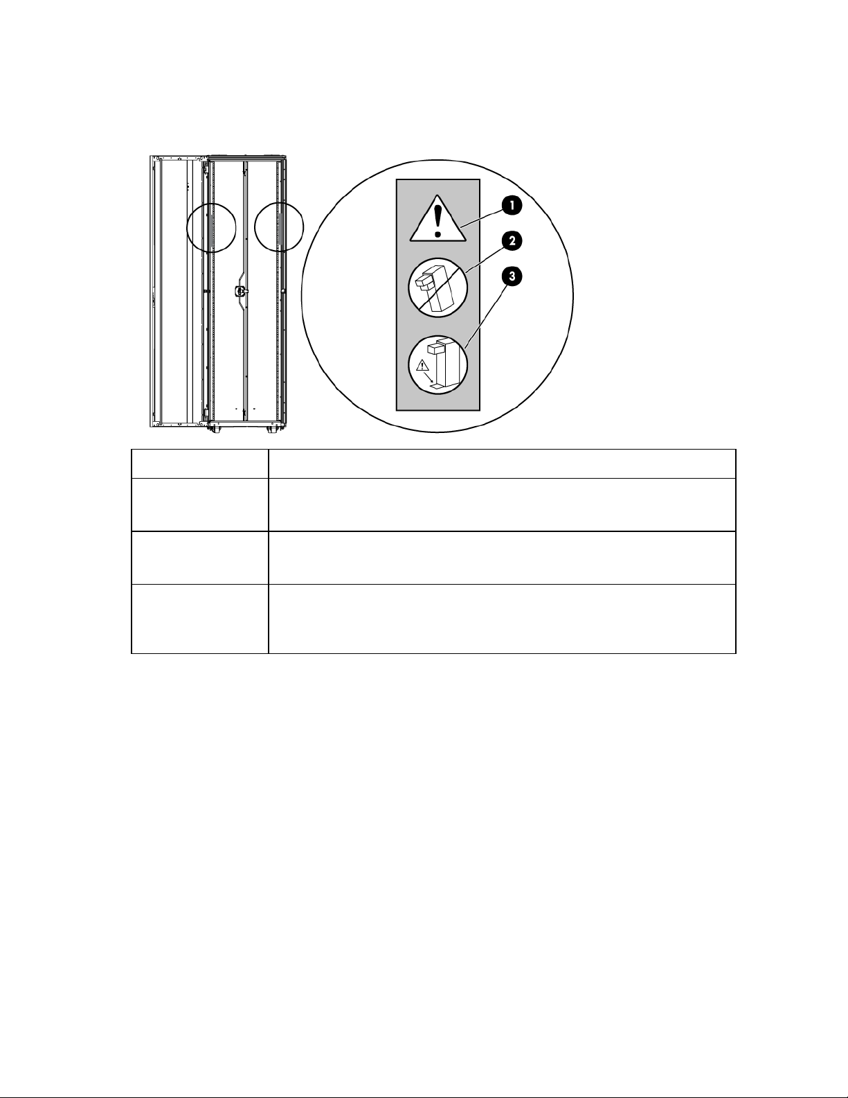
Warning labels
This symbol in conjunction with any of the following symbols indicates the presence of
This symbol indicates the presence of risk of personal injury as the rack may become
This symbol is to ensure that the rack is adequately stabilized before extending a
The following warning labels are located on the rack.
Item Description
1
a potential hazard. The potential for injury exists if warnings are not observed. Consult
your documentation for specific details.
2
unstable if more than one component within the rack is extended for any reason.
WARNING: To reduce the risk of injury only extend one component at a time.
3
component outside of the rack. Consult your documentation for specific details on how
to stabilize the rack.
WARNING: To reduce the risk of injury verify the rack is stabilized.
About this guide 8
Page 9

Rack options
AF076A
BW927A
Seismic anchoring of rack
BW937A
Removes warm air from the rack by channeling
BW926A
Seismic anchoring of the rack
HP LED Light kit
BW939A
Enables you to add a light to the rack
100 Kilo Sliding Shelf kit
234672-B21
Enables easy access to various rack components
BW928A
BW929A
Ensures proper airflow within the rack
BW930A
Improves rack airflow of your rack by preventing hot air
120672-B21
Provides additional stability and support when heavy
Baying kit
BW902A
Joins multiple racks of the same series, height, and depth
AF099A
Enables you to manage your cable configurations
Cable Management Ring
168233-B21
Allows cables to be routed and organized within the rack
Ordering rack options
HP provides several rack option kits to complement or complete your rack solution. The following tables are
lists of the available rack option kits for each series.
For information about ordering rack option kits, contact your nearest HP authorized reseller, or see the HP
website (http://www.hp.com/go/rackandpower).
HP Advanced Series Racks
Rack option kit Part number Description
Tie-down kit (on page 98)
--or-BW926A
--or--
HP Enterprise Series Racks
Rack option kit Part number Description
Air Duct kit¹
Tie-down kit
the warm air into the data center ceiling return
air plenum
¹For rack part numbers BW910A and BW936A only
HP Advanced Series Racks and HP Enterprise Series Racks
Rack option kit Part number Description
1U Universal Filler Panel
Airflow Optimization kit
Ballast kit
--or--
recirculation to the front of the rack
equipment is installed, removed, or accessed within the
rack
Cable Management Bracket kit
Rack options 9
Page 10

Rack option kit Part number Description
383982-B21
383984-B21
Enables you to manage your cable configurations
BW935A
Enables you to add your own brand name label to the rack
BW934A
Replacement door compatible with HP Advanced Series
BW891A
Reduces the level of electromagnetic emissions outside the
Heavy Duty V2 Stabilizer kit
BW961A
Increases the stability of free-standing racks
Clip kit
379820-B21
Enables you to manage your cable configurations
BW963A (10
PK)
Enables you to manage your cable configurations
Cover kit
BW942A
Covers for location discovery contacts
BW945A
F9V74A
Enables you to find which rack in which a server is located
BW941A
BW952A
Enables you to connect multiple racks of different depths
Rack Hardware kit
H6J85A
Mounting hardware kit
257413-B21
257414-B21
Enhances natural convection cooling within the rack
Server/utility shelf kit
253449-B21
Holds rack components inside of the rack
BW898A
Provides enclosures for the sides of a rack
Cable Management tray kit
--or-383983-B21
--or--
Custom Door Branding kit
Enterprise Series Front Door kit
Ground Bonding kit
Hook-and-loop Cabling Srap
1/4 Turn Hook and Loop
Cabling Strap kit
Location Discovery Contact
Location Discovery kit
Offset Baying kit
PK)
--or-BW964A (100
--or-BW946A
--or-BW947A
--or--
--or--
Racks and Enterprise Series Racks
rack
as well as the location inside the rack
together
Roof Mount Fan kit
Side Panel kit
--or--
--or-BW901A
--or-BW906A
--or-BW909A
--or-BW915A
--or-BW916A
--or-H6J91A
Rack options 10
Page 11

BW932A
BW961A
Increases the stability of free-standing racks
Rack option kit Part number Description
Stabilizer kit
--or-BW933A
--or--
Rack options 11
Page 12
100 Kilo Sliding Shelf kit
Shelf with handle
1
Right rail with fixed brackets
1
Left rail with fixed brackets
1
Sliding rail
2
hardware
1
Rack template
1
•
•
•
•
•
•
•
•
•
•
•
•
•
•
About this device
The HP 100 Kilo Sliding Shelf kit enables you to install a sliding shelf in your rack mount system for placement
and easy access to various components. This option occupies 2Us of rack space.
Kit contents
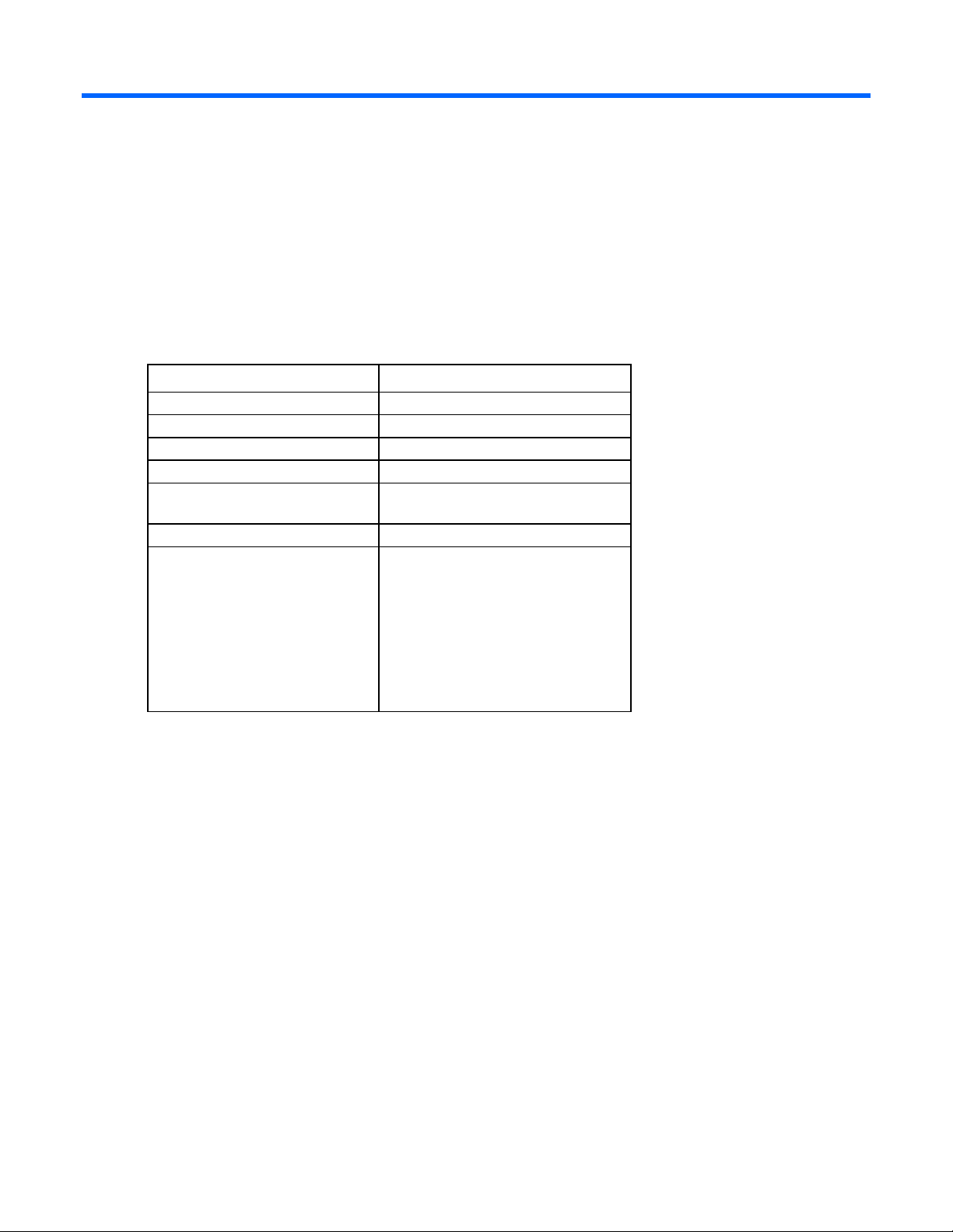
Item Quantity
Cable management arm with
Hardware kit
M4 x 12 flat HD screw
M4 external washer
M4 x 10 pan HD screw
M6 x 12 pan HD screw
M4 plain washer
M4 nut
M6 external washer
Extra hardware might be included for your convenience.
Required tools
8
8
2
12
2
6
10
The following tools are required for installation:
• No. 2 Phillips screwdriver
• No. 3 Phillips screwdriver
Preparing the sliding shelf rail assemblies for installation
Each sliding shelf rail assembly consists of a rail with fixed brackets attached to a sliding rail. To construct the
sliding shelf rail assemblies:
1. Hold the flat side of the left rail with fixed brackets facing toward you.
2. Place the sliding rail on top of the left rail with fixed brackets.
100 Kilo Sliding Shelf kit 12
Page 13
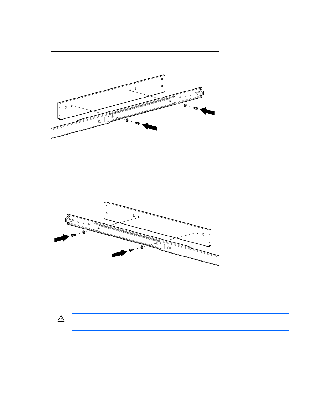
Extend the inner slides of the sliding rail until the screw holes on the sliding rail and the left rail with fixed
the equipment, be sure to secure
3.
brackets are aligned. Gently push down on the sliding rail to lock it into place.
4. Secure the rails together with two M4 x 12 flat HD screws and M4 external washers.
5. Repeat steps 1 through 4 for the right rail with fixed brackets.
Installing the sliding shelf rail assemblies
WARNING: To reduce the risk of personal injury or damage to
You must install the sliding shelf rail assemblies before installing the sliding shelf. Follow these steps closely
to install the sliding shelf rail assemblies into the rack:
mounted rack components when moving the rack.
100 Kilo Sliding Shelf kit 13
Page 14
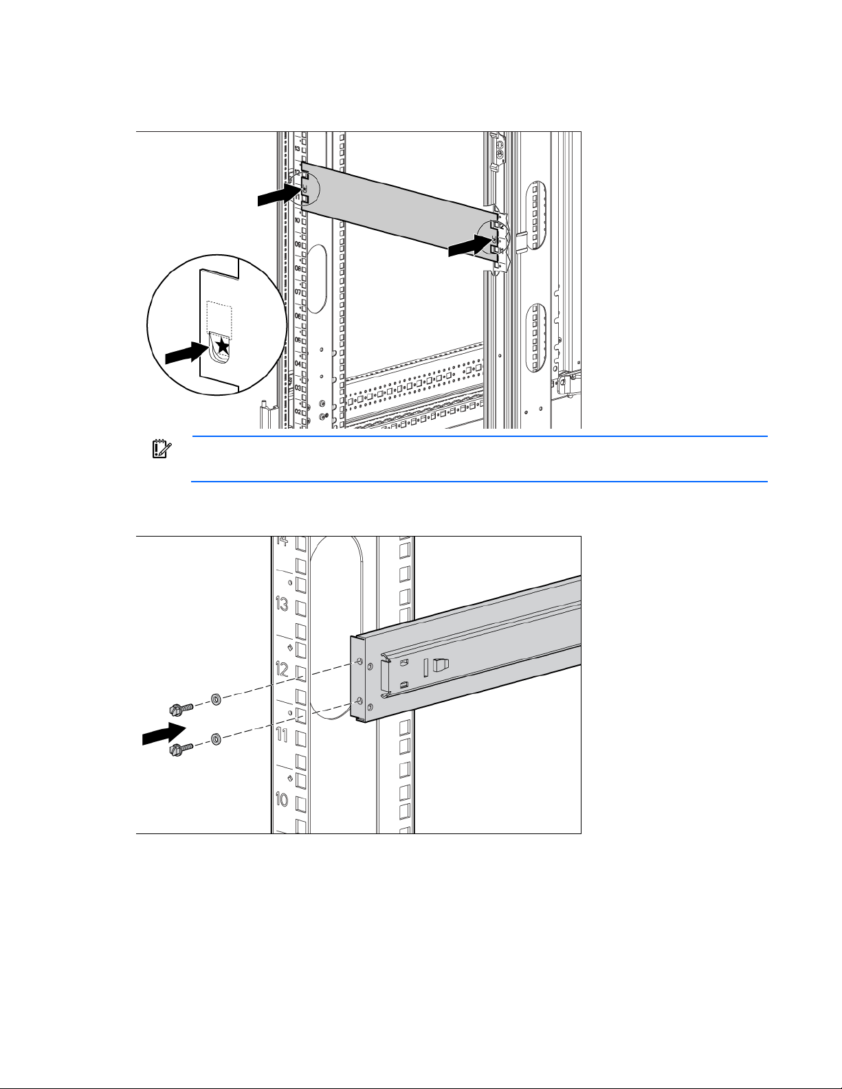
Use the template on the front and rear of the rack frame to mark the attachment points for the sliding
1.
shelf rail assemblies, by measuring from the top of the component installed below the desired position
for the sliding shelf.
IMPORTANT: When using the template on the rear of the rack frame, mark the rack at the top of
the template to help align the next rack component.
2. Align and secure the rear of the left sliding shelf rail assembly to the rear of the rack frame with two M6
x 12 pan HD screws and M6 external washers.
100 Kilo Sliding Shelf kit 14
Page 15
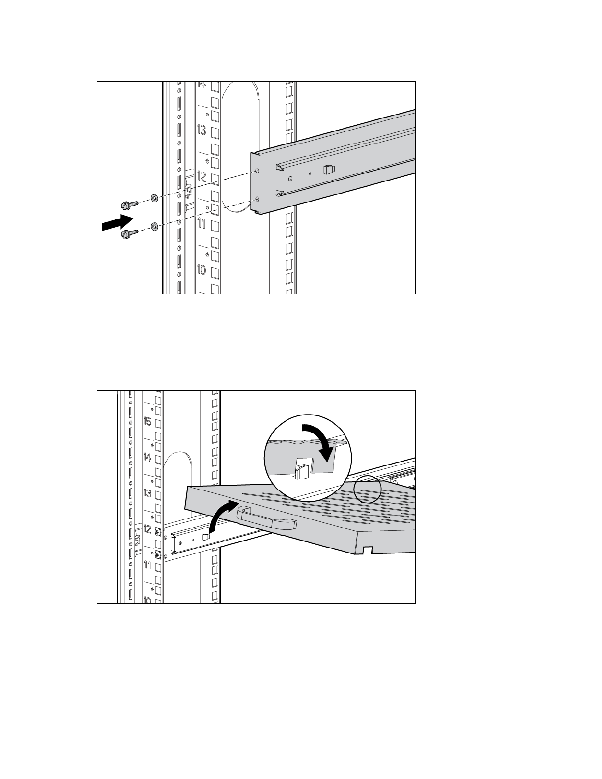
Secure the front of the left sliding shelf rail assembly to the front of the rack frame with two M6 x 12 pan
3.
HD screws and M6 external washers.
4. Repeat steps 2 and 3 to install the right sliding shelf rail assembly.
Installing the sliding shelf
1. Move the sliding shelf into the rack while tilting the front of the shelf up. Align the rear notches on the
sliding shelf over the rear tabs on the sliding shelf rail assemblies.
2. Push the sliding shelf down onto the rear tabs to align the front notches on the sliding shelf with the front
tabs on the sliding shelf rail assemblies.
3. Lower the front of the sliding shelf over the tabs on the front of the sliding shelf rail assemblies and push
down gently to lock the shelf into place.
100 Kilo Sliding Shelf kit 15
Page 16
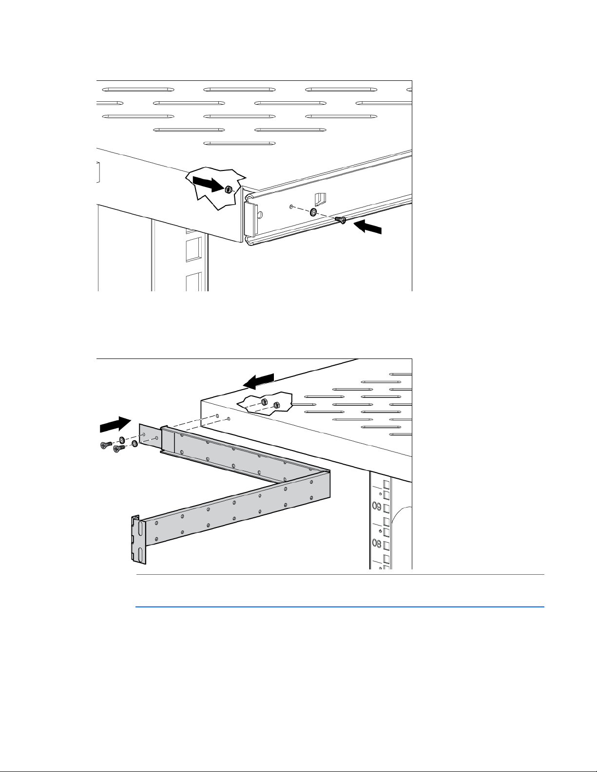
Secure the sliding shelf to each sliding rail using one M4 x 12 flat HD screw and M4 external washer
4.
with one M4 nut on the inside of the shelf.
5. Attach the cable management arm to the sliding shelf with the flat side of the cable management arm
mounting bracket flush with the sliding shelf.
6. Secure the cable management arm to the sliding shelf using two M4 x 12 flat HD screws and M4
external washers with two M4 nuts on the inside of the shelf.
NOTE: The cable management arm attaches to the rear of the sliding shelf on either the right or
left side.
100 Kilo Sliding Shelf kit 16
Page 17
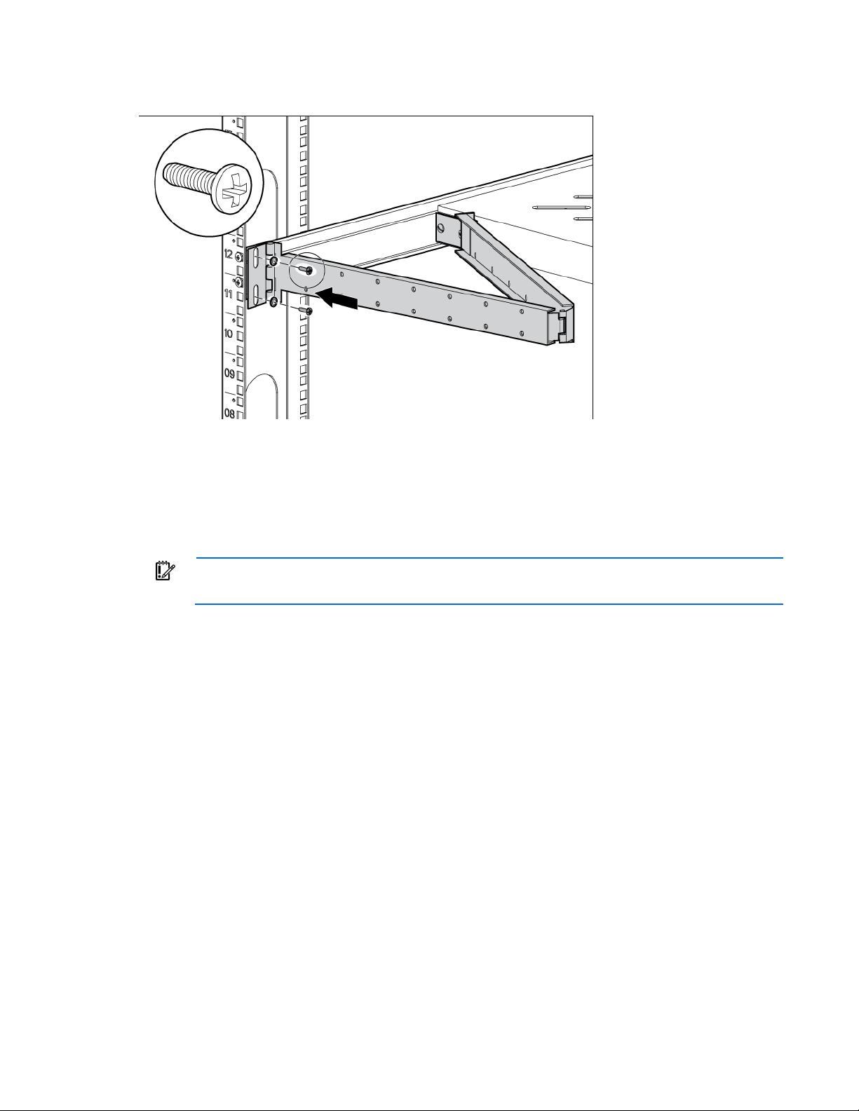
Be sure to secure all rack mount system components when moving the shelf out of
Secure the opposite end of the cable management arm to the rack using two M6 x 12 pan HD screws
7.
and M6 external washers.
Installation is complete.
Using the 100 Kilo Sliding Shelf
Use the handle on the front of the sliding shelf to slide it in and out of the rack. When sliding the shelf back
into the rack, there may be resistance. Apply pressure as needed to fully move the shelf into the rack.
IMPORTANT:
the rack.
100 Kilo Sliding Shelf kit 17
Page 18
Air Duct kit
Air Duct Kit
This kit includes the upper chimney and the lower
About this device
The Air Duct kit removes warm air from the HP 42U 600x1200mm Enterprise Air Duct Rack and the HP 47U
600x1200mm Enterprise Air Duct Rack by channeling the warm air into the data center ceiling return air
plenum. The air duct sits on top of the rack, which is directly joined to the ceiling plenum. The air duct position
prevents the warm air from entering the data center aisle.
This kit is required for the HP Air Duct Enterprise Series Racks BW910A and BW936A.
Kit contents
Part number Option kit name Description
BW937A
Required tools
The following tools are required for installation:
• T-25 Torx driver
• T-30 Torx driver
• Adjustable wrench or 17-mm wrench
• Scissors
• Electric drill
• 2.38-mm (3/32-in) drill bit
chimney.
Assembling the air ducts
1. Assemble the lower duct:
a. Align the hooks of the side panels with the slots of the front and back panels (1).
b. Slide the six hooks into the slots, and then slide the panel down until it locks in place (2).
Air Duct kit 18
Page 19
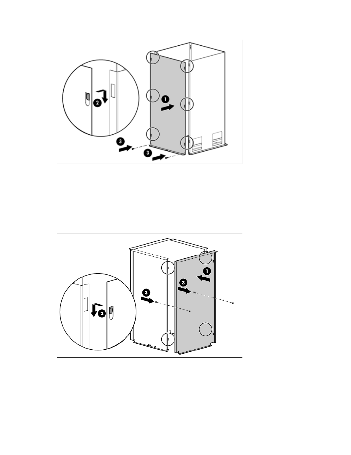
Insert one M5.5 self-tapping screw into each bottom corner of the assembly (3).
c.
d. Repeat steps a through c for the other side panel.
2. Assemble the upper duct.
a. Align the hooks of the side panels with the slots of the front and back panels (1).
b. Slide the six hooks into the slots, and then slide the panel down until it locks in place (2).
c. From the inside of the assembly, insert two M6 cap screws in the middle of the assembly. Using an
adjustable wrench, secure the screws from outside the assembly with an M6 star washer, an M6 flat
washer, and a nut (3).
d. Repeat steps a through c for the other side panel.
3. Install the draw-latch straps to the upper duct assembly.
a. Slide the draw-latch strap around the bottom of the upper duct assembly (1).
b. Align the holes of the draw-latch strap with the holes of the upper duct assembly.
Air Duct kit 19
Page 20
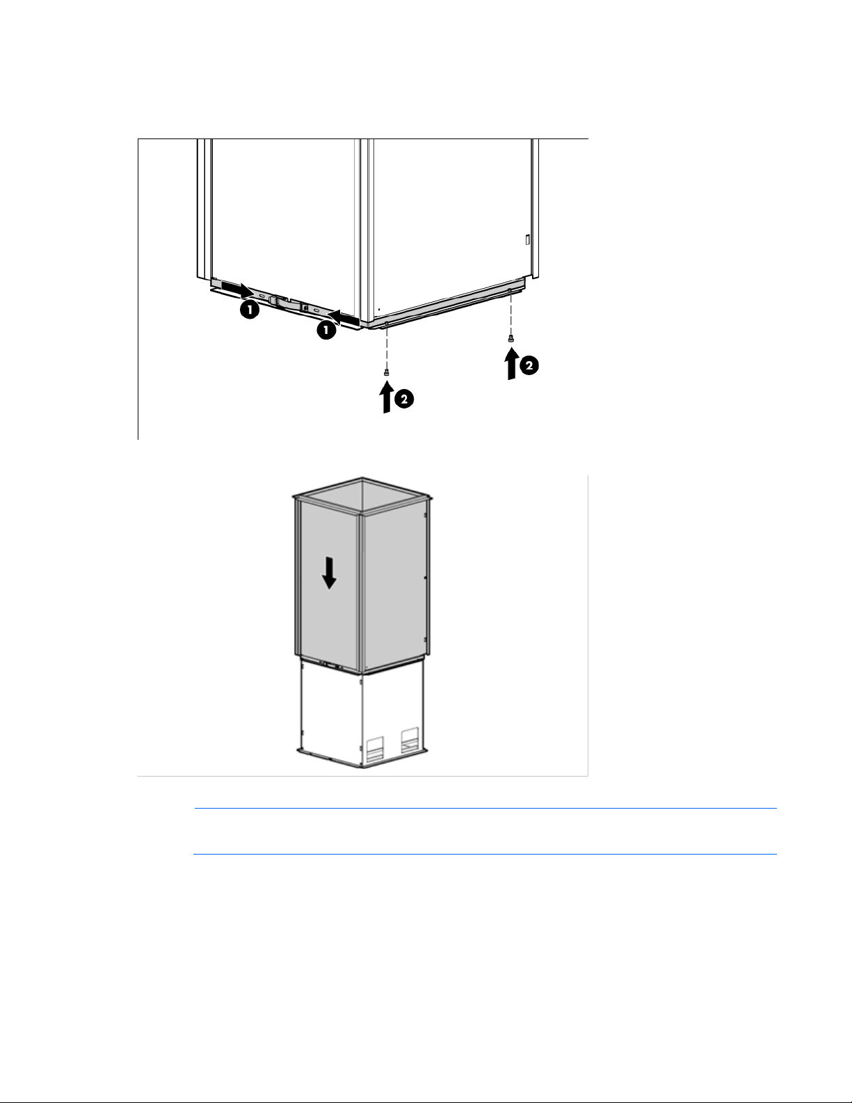
Insert two plastic push fasteners into the holes on both sides of the assembly to secure the draw-latch
c.
strap to the upper duct assembly (2).
d. Repeat steps a through c for the second draw-latch strap.
4. With the draw-latch straps in the loose position, slide the upper duct down over the lower duct.
5. Lock the draw-latch straps.
NOTE: The two 510-mm gaskets sit on the inside edges of the two 520-mm gaskets.
Air Duct kit 20
Page 21
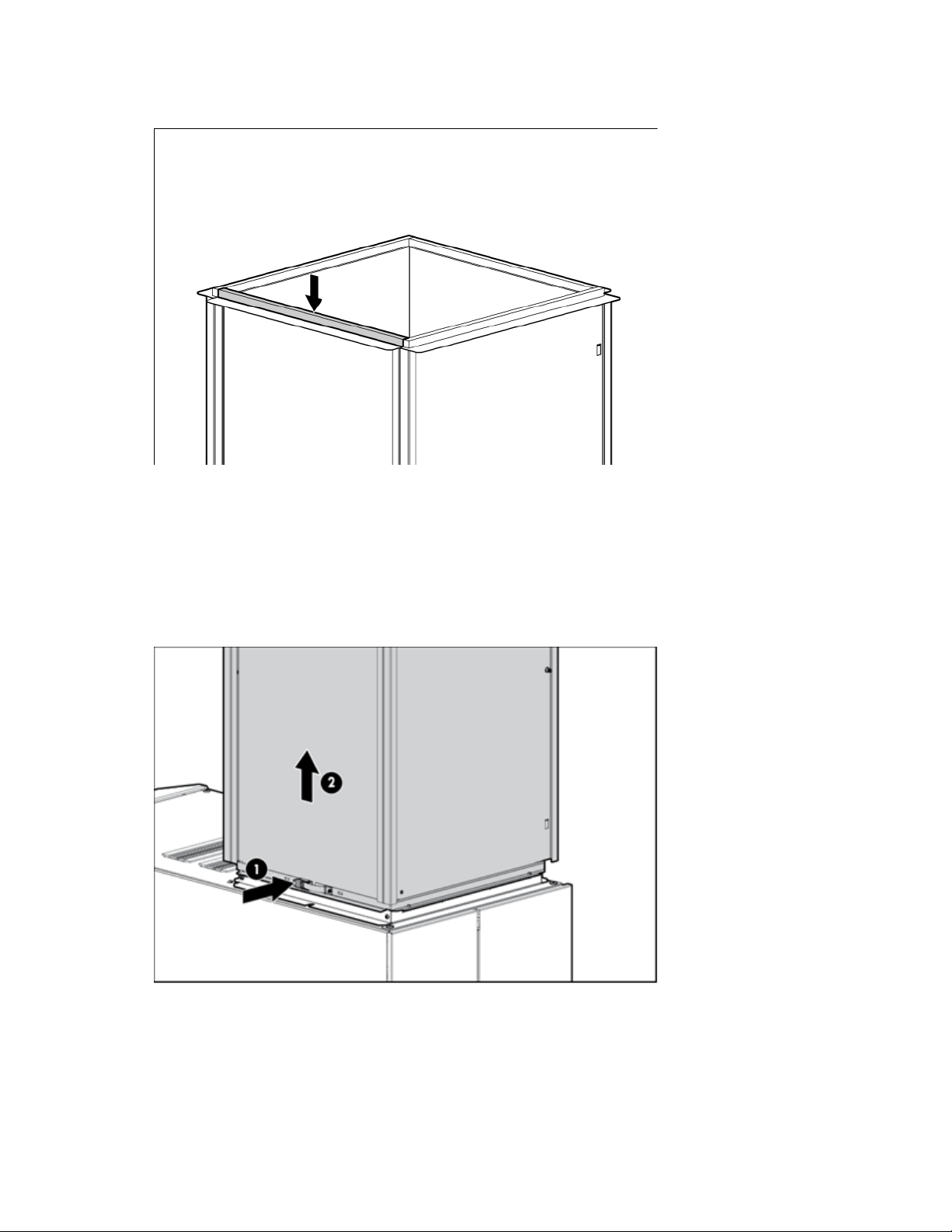
Apply the foam gasketing to the top of the upper duct by peeling the adhesive backing and aligning the
6.
gasketing with the top edges of the upper duct.
Adjusting the air duct
After you have installed the air duct to the top of your rack:
1. Loosen both draw-latch straps (1).
2. Raise the upper duct until it reaches the ceiling opening, and the gasketing is pressed firmly against the
ceiling (2).
3. Tighten and lock both draw-latch straps to hold the upper duct in place (1).
4. To lock the air duct in the raised position:
a. Mark through the predrilled hole on the upper duct, so you know where the hole should be on the
lower duct.
Air Duct kit 21
Page 22
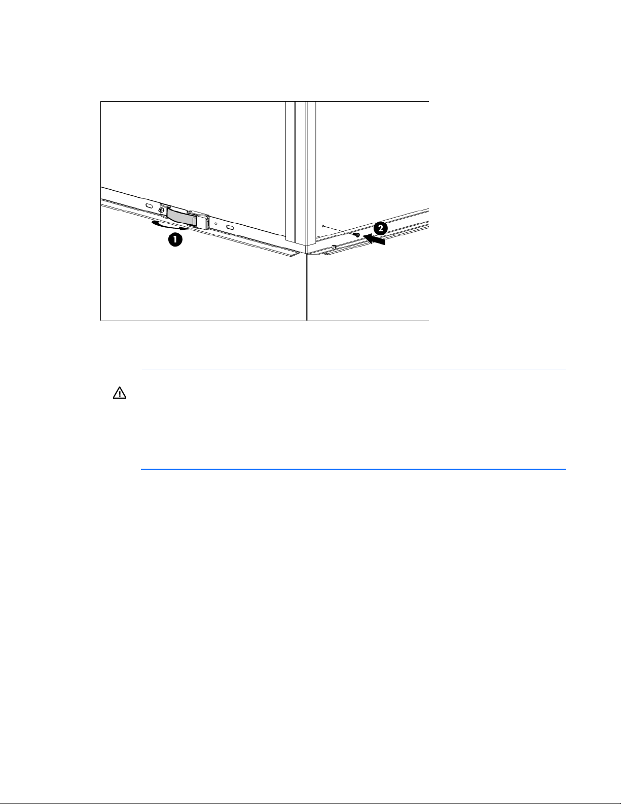
Using an electric drill, drill one 2.38-mm (3/32-in) hole through the lower duct, in the location that
b.
you marked.
c. Insert one M3.5 self-drilling screw through the holes in both the upper and lower ducts (2).
Installing the air duct assembly
WARNING: The rack air duct weighs approximately 22.5 kg (50 lb). To reduce the risk of
personal injury or damage to the equipment:
• Observe local occupational health and safety requirements and guidelines for manual
material handling.
• Use at least two people to lift and stabilize the product during installation or removal.
• Use step stools to install the product to the top of the rack. Do not lift the air duct over your
1. Using a T-30 Torx screwdriver, remove the two screws in the rear corners of the rack, and then remove
the bracket.
2. Slide the air duct toward the front of the rack, until the front edge slides under the metal slots on the top
plate of the rack (1).
3. Place the bracket back into place (2).
head.
Air Duct kit 22
Page 23
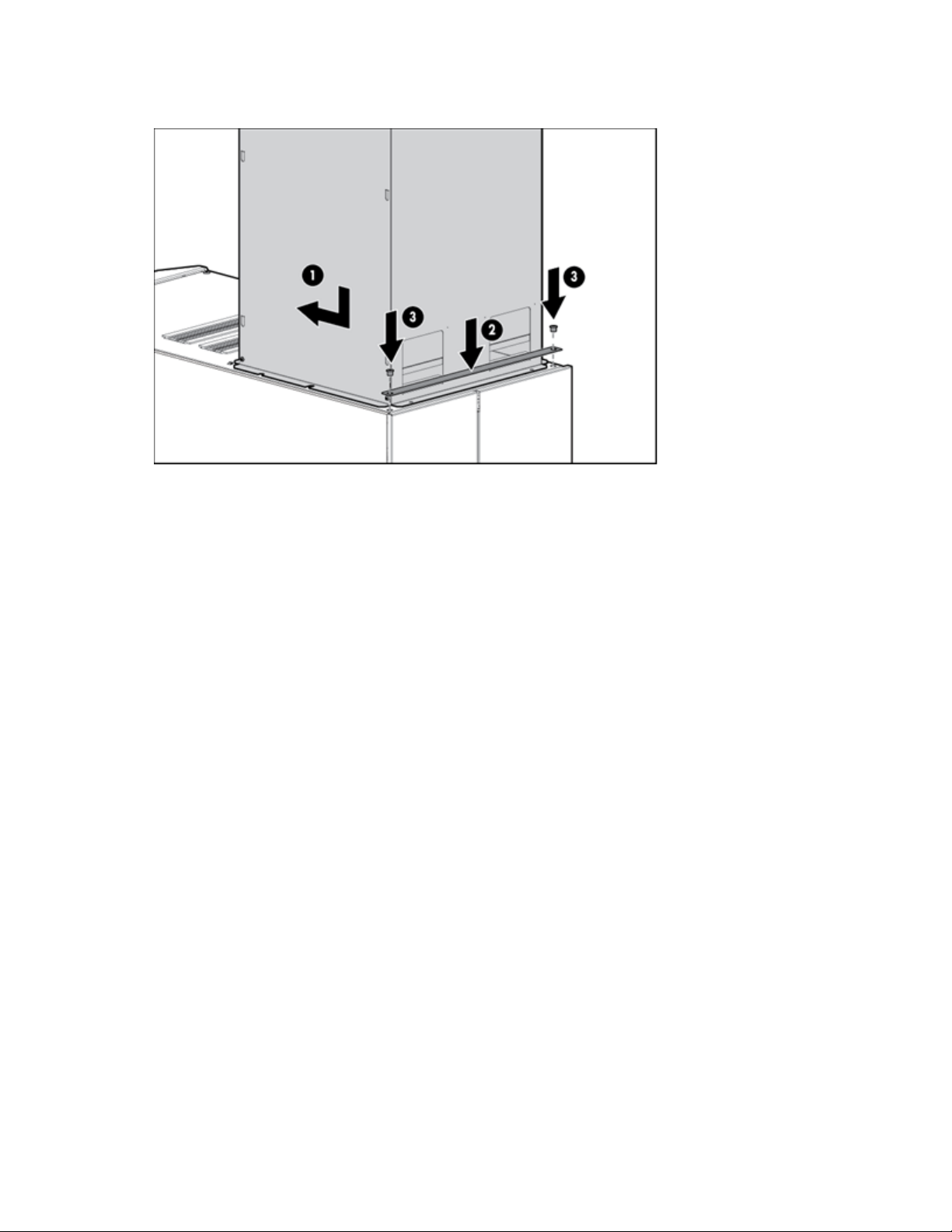
Insert the two screws (from step 1) through the holes of the bracket and into the two rear holes of the rack
4.
(3), and then tighten them using a T-30 Torx screwdriver.
Air Duct kit 23
Page 24
Airflow Optimization kit
Foam rail gasket roll
4
gasket
1
The foam rail gasket must be installed into the rack before two or more racks can be
.
About this device
The Airflow Optimization kit enables you to install foam rail gaskets in your HP Advanced Series Racks and
Enterprise Series Racks 36U, 42U, and 47U 600-mm (24-in) wide racks and in to 42U 800-mm (31-in) wide
racks to improve separation between hot and cold aisles in the data center.
Kit contents
Item Quantity
600-mm (24-in) perforated floor
gasket
—or—
800-mm (31-in) perforated floor
Extra hardware might be included for your convenience.
Required tools
No tools are required for this procedure.
Installing foam rail gaskets between racks
CAUTION:
If installing the foam rail gasket between racks that have a baying kit installed, the baying bracket must be
removed before the foam rail gasket can be inserted between the racks.
bayed together. For additional information on baying racks, see the HP Baying Rack Option Kit
1. Position the racks side by side.
2. Cut the foam rail gasket to fit the size of your rack.
Airflow Optimization kit 24
Page 25
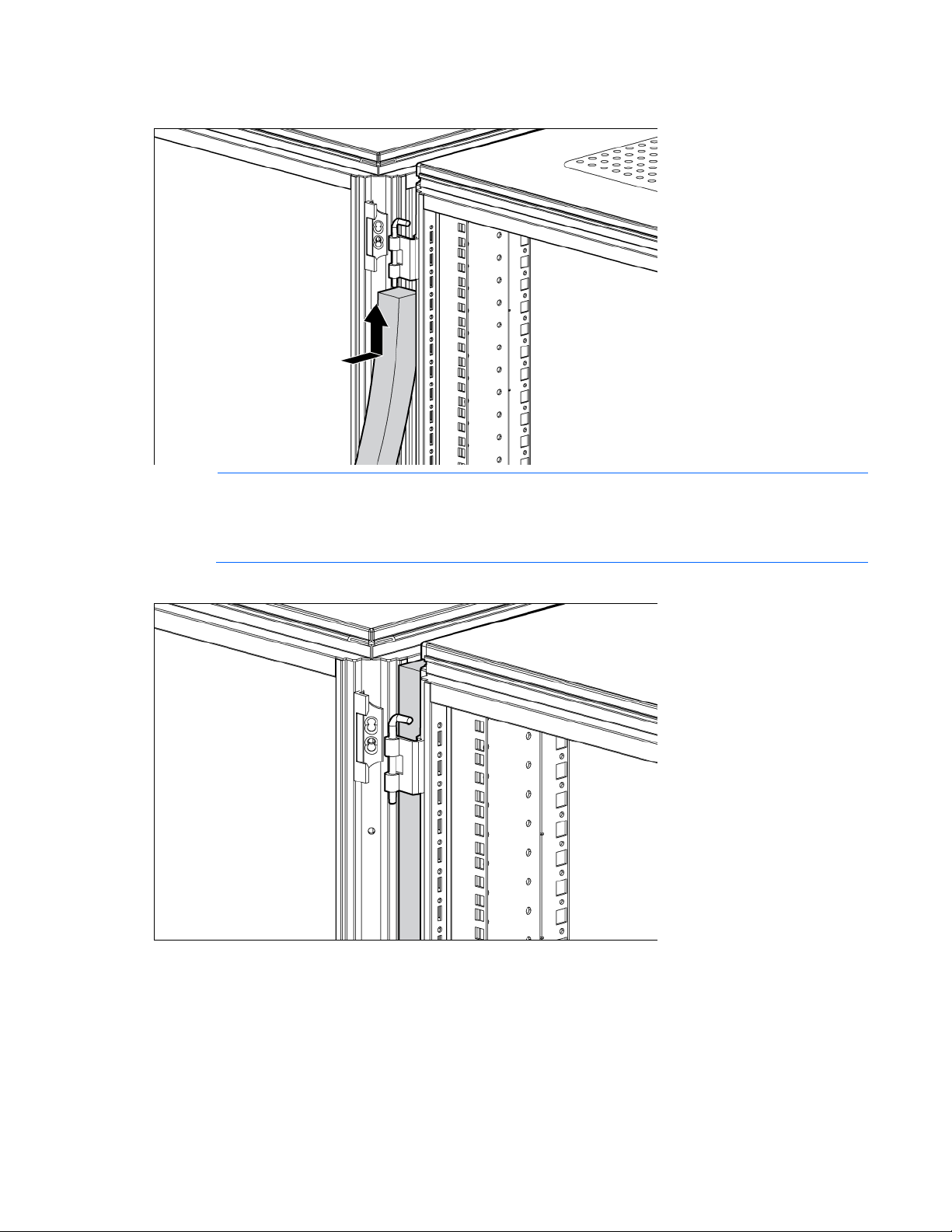
Insert the foam rail gasket into the space between the racks with the closed cell side of the foam rail
Follow steps 1 through 3 to install the foam rail gasket into a rack that will be bayed using
3.
gasket facing the front of the rack.
NOTE:
a 24-in. baying bracket.
If the rack will be bayed using a 600-mm baying bracket, rotate the foam rail gasket 90 degrees
4. Gently push the foam rail gasket into the space between the racks until it is flush with the vertical frame.
before inserting it into the space between the racks.
Airflow Optimization kit 25
Page 26
Installing the floor gasket
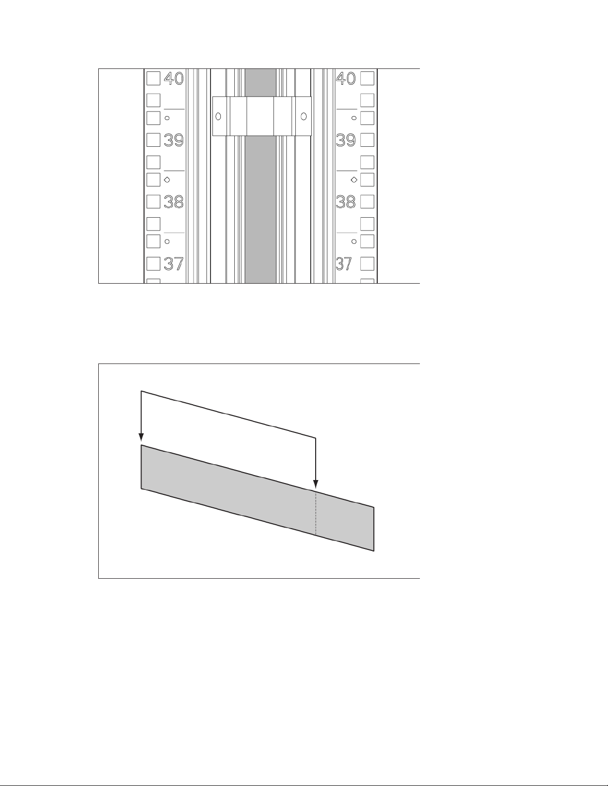
1. Depending on the size of your rack, cut the floor gasket at the perforation to reduce the length from
800-mm (31 in) to 600-mm (24 in).
Airflow Optimization kit 26
Page 27
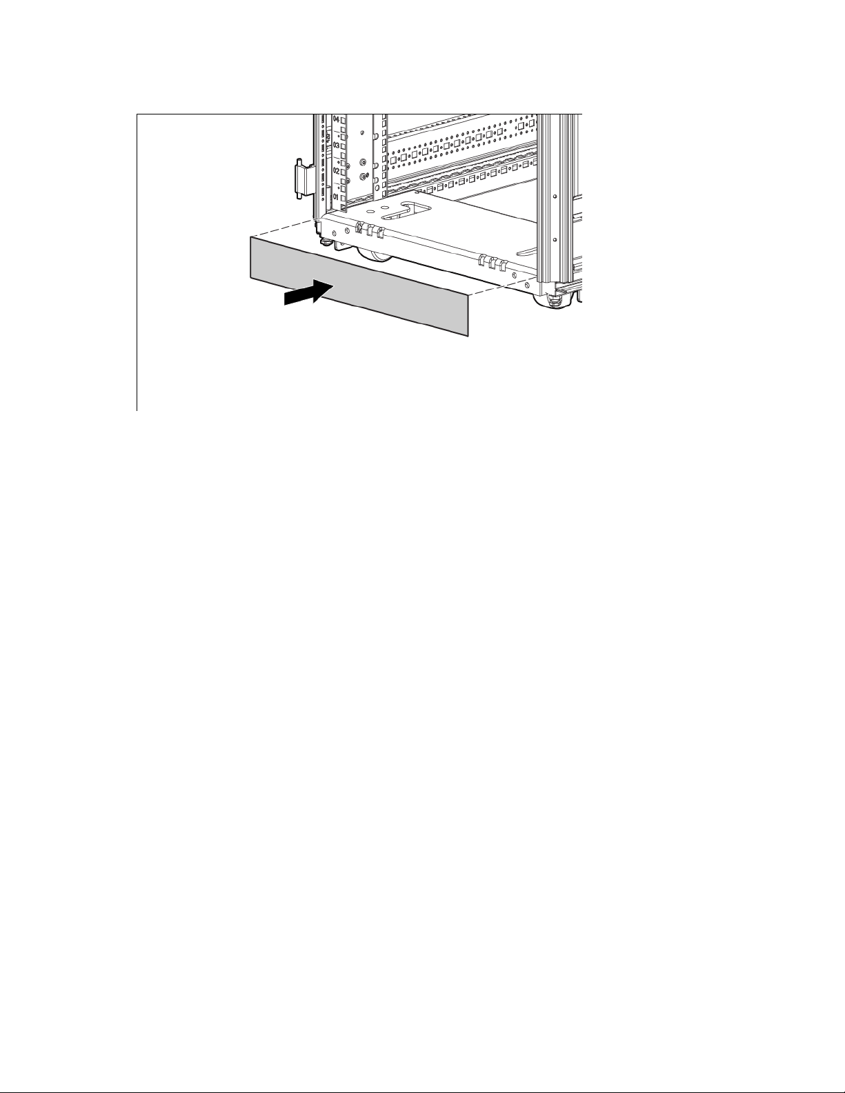
Remove the protective tape from the bottom edge of the floor gasket, and then apply the gasket to the
2.
bottom of the rack with the adhesive strip facing the front of the rack.
Installation is complete.
Airflow Optimization kit 27
Page 28
Baying kit
24-inch baying brackets
6
600-mm baying brackets
6
T-30 Torx screws
15
About this device
The Baying kit enables you to connect multiple HP Advanced Series Racks and Enterprise Series Racks of the
same series, height, and depth.
Kit contents
Item Quantity
Extra hardware might be included for your convenience.
Installing the baying kit
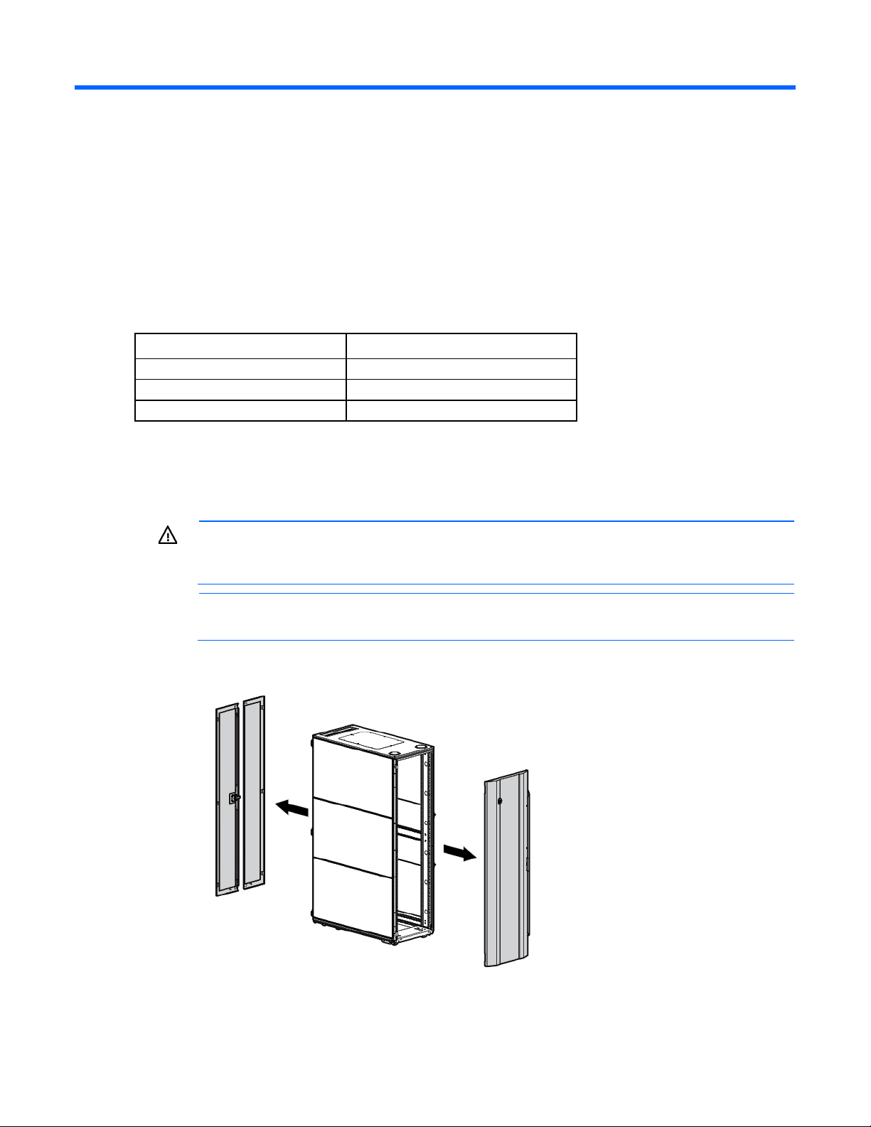
WARNING: To reduce the risk of personal injury or damage to the rack and equipment, the
racks must be positioned and secured together according to these instructions. Failure to do so
1. Remove the front and rear doors.
could result in an unstable installation.
NOTE: The appearance of the rack might vary depending on the model of the rack purchased.
2. Remove the side panels (if present between the racks).
Baying kit 28
Page 29
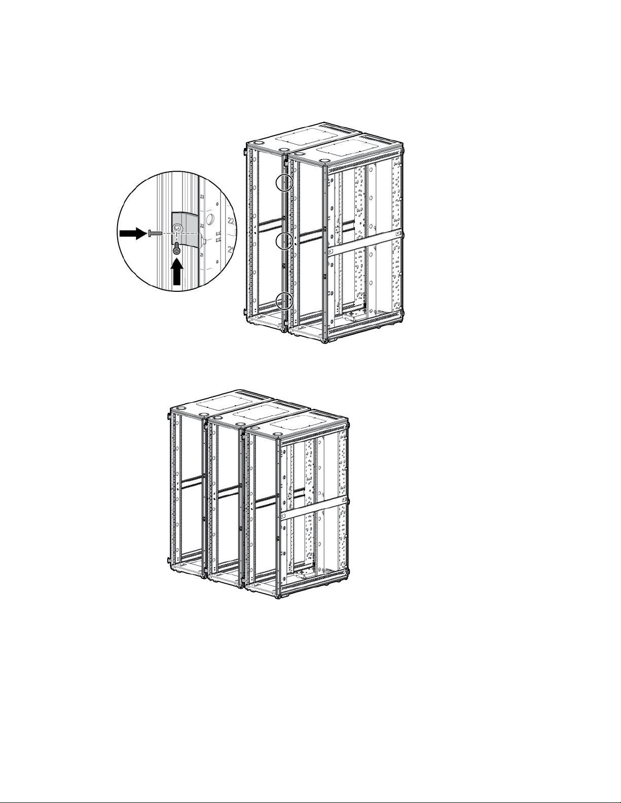
Position the racks side by side, ensuring that the feet of the racks are on solid flooring (no cracks or
3.
openings).
4. Using two T-30 Torx screws in each bracket, attach three baying brackets (either 24-inch or 600-mm,
depending on the floor layout) to the front and rear of each rack set.
5. Bay any additional racks.
6. Attach side panels to each end of the bayed racks, and then re-attach the front and rear doors.
Installation is complete.
Baying kit 29
Page 30
Custom Door Branding kit
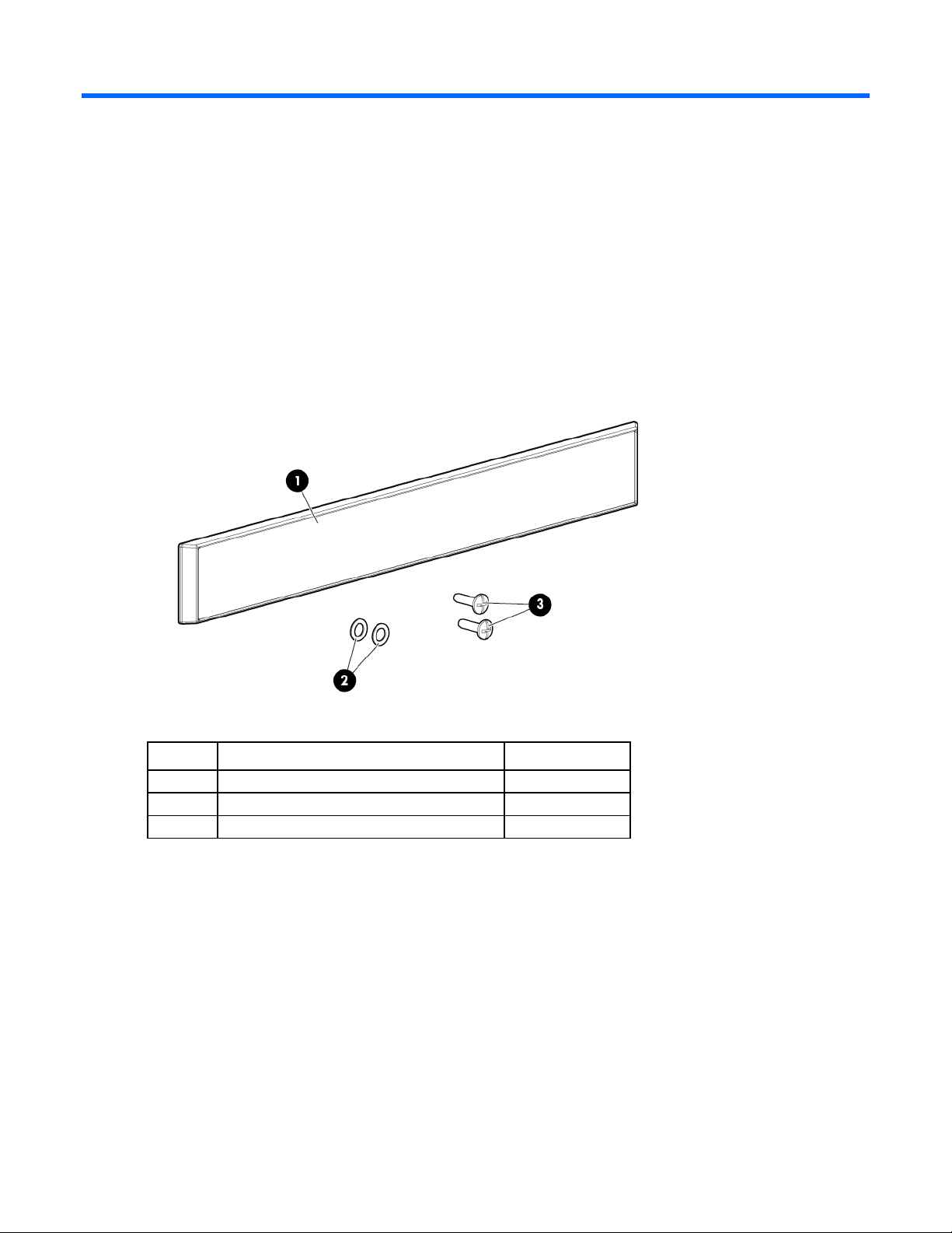
1
Bezel
1 2 10.5 mm OD washers with 8mm countersink
2
3
6mm T-10 Torx flathead screws
2
About this device
The Custom Door Branding kit enables you to install a bezel with your company's name at the top of the HP
Kit contents
Advanced Series Racks and Enterprise Series Racks.
If any of the following items are missing or damaged, contact your HP authorized reseller.
Item Description Quantity
Required tools
T-10 Torx screwdriver
Installing the custom door branding kit
Remove the bezel, two washers, and two screws from the Custom Door Branding kit. It might be helpful to
have another person help you install the bezel.
1. Place the bezel near the top of the rack door, and align it with the two holes near the top of the door.
2. Open the rack door.
Custom Door Branding kit 30
Page 31
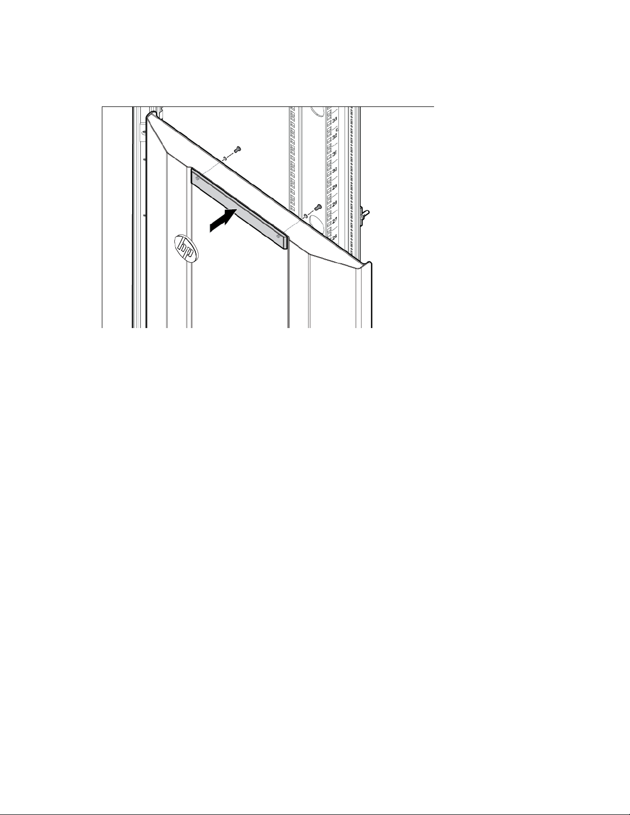
From the back of the rack door, position one of the washers over the hole near the top.
3.
4. While holding the washer in place, insert the screw, and then tighten the screw with a screwdriver.
5. Repeat steps 4 and 5 for the second washer and screw.
Installation is complete.
Custom Door Branding kit 31
Page 32

Cable Management Bracket kit
1U cable management bracket
1
2U cable management bracket
1
clips
10
10
Cross-over brackets
2
10
strap clips
10
10
M6 cage nuts
11
M6 x 16-mm Torx screws
11
M5.5-mm x 10-mm Torx screws
9
1/4 turn plastic latches
6
About this device
The HP Cable Management Bracket kit assists with cable management and is designed for use with all HP
racks.
Kit contents
Item Quantity
Cable management D-ring bracket
Cable management D-ring bracket
clamps
12.7-cm (5-in) hook-and-loop cabling
strap
20.3-cm (8-in) hook-and-loop cabling
1/4 turn hook and loop cabling strap
Extra hardware might be included for your convenience.
Required tools
The following tools are required for installation:
• T-25 Torx driver
• Cage nut insertion tool (included with your original rack hardware kit)
Cable Management Bracket kit 32
Page 33
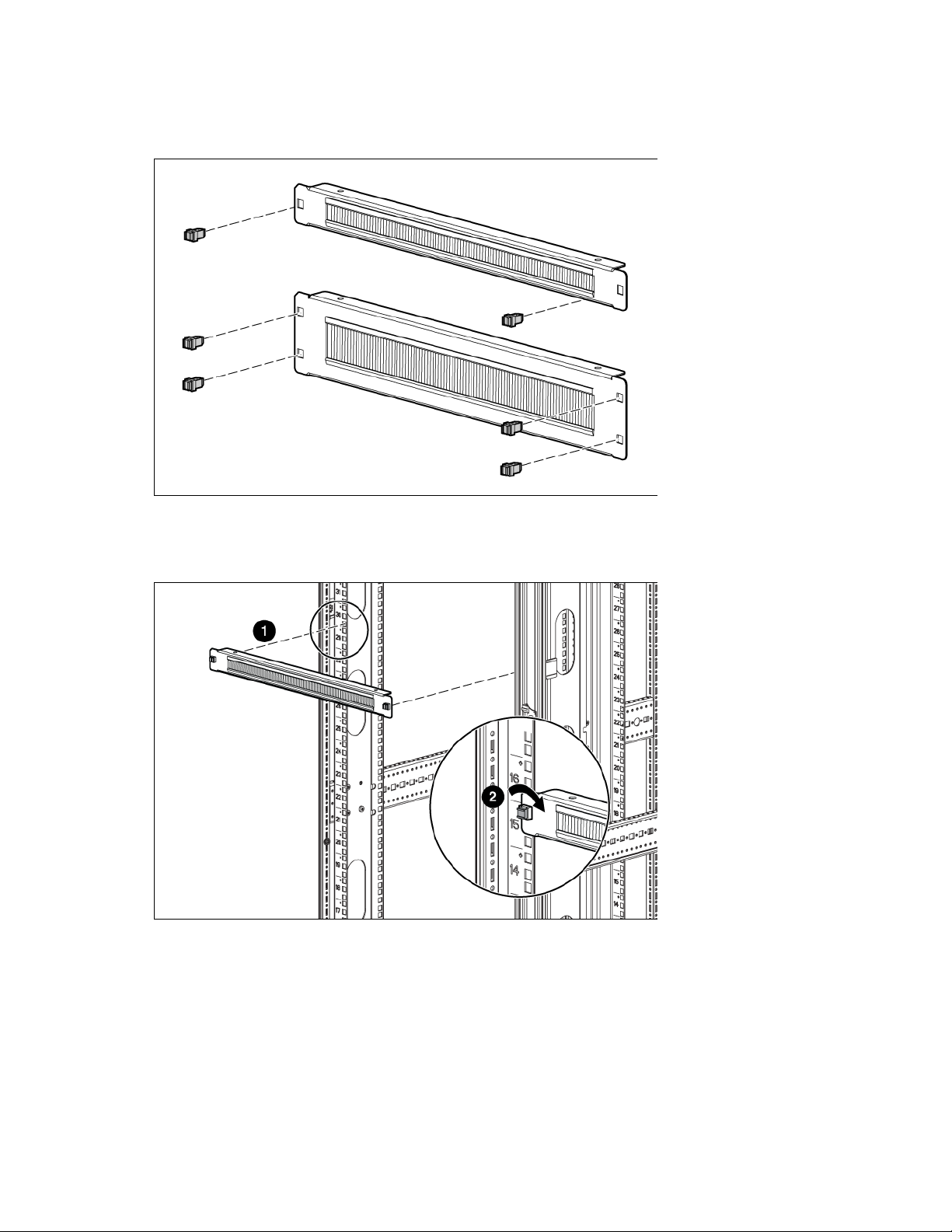
Installing the 1U cable management bracket
1. Insert one 1/4 turn plastic latch on either side of the 1U cable management bracket.
2. Align the 1U cable management bracket to the screw holes in the desired location of the rack (1).
3. Turn the 1/4 turn plastic latch on either side of the 1U cable management bracket clockwise until it locks
in place (2).
Cable Management Bracket kit 33
Page 34
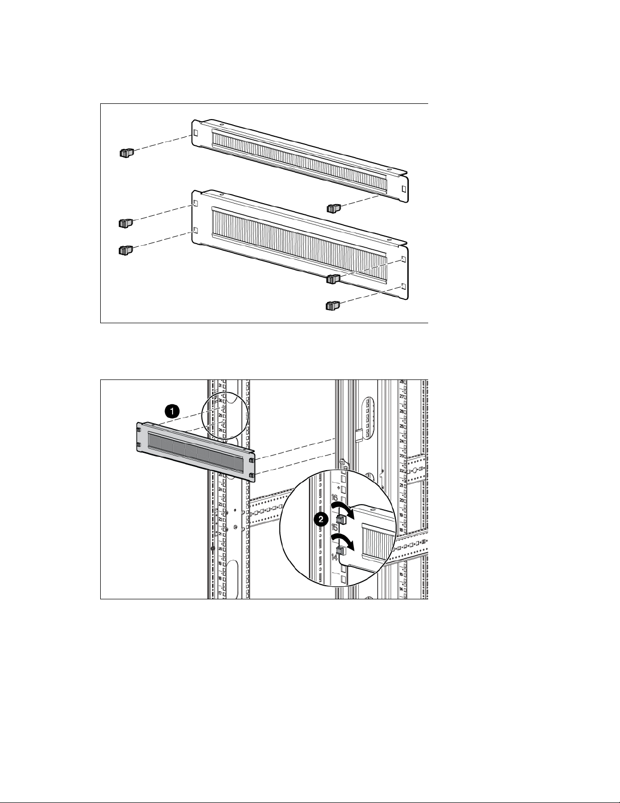
Installing the 2U cable management bracket
1. Insert two 1/4 turn plastic latches on either side of the 2U cable management bracket.
2. Align the 2U cable management bracket to the screw holes in the desired location of the rack (1).
3. Turn the two 1/4 turn plastic latches on either side of the 2U cable management bracket clockwise until
they lock in place (2).
Installing the cable management D-ring bracket
The cable management D-ring bracket can be installed in either a front mount or a side mount, depending on
your rack configuration.
Cable Management Bracket kit 34
Page 35
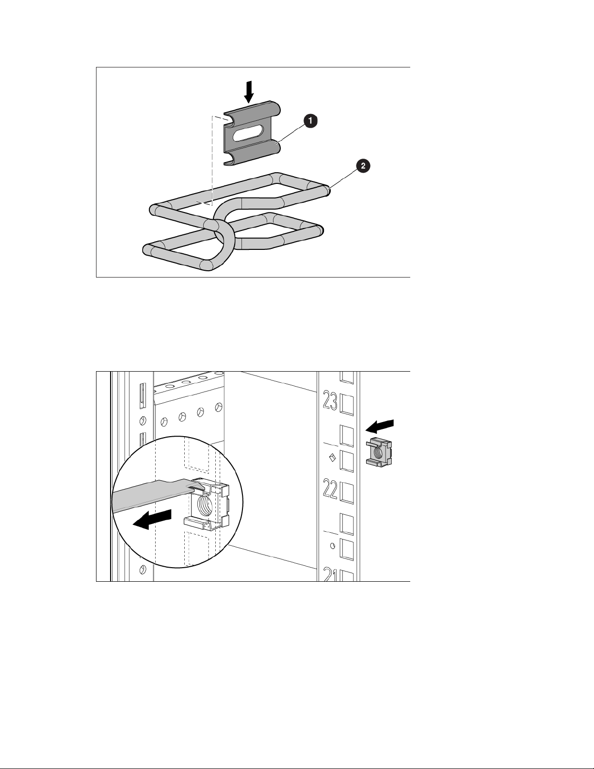
Place a cable management D-ring bracket clip (1) on a cable management D-ring bracket clamp (2).
1.
2. Install the cable management D-ring bracket in a front mount ("Front mount" on page 35).
3. Install the cable management D-ring bracket in a side mount ("Side mount" on page 36).
Front mount
1. Using a cage nut insertion tool, install an M6 cage nut into the desired location on the front of your rack.
2. Align the cable management D-ring bracket with the previously installed M6 cage nut (1).
Cable Management Bracket kit 35
Page 36
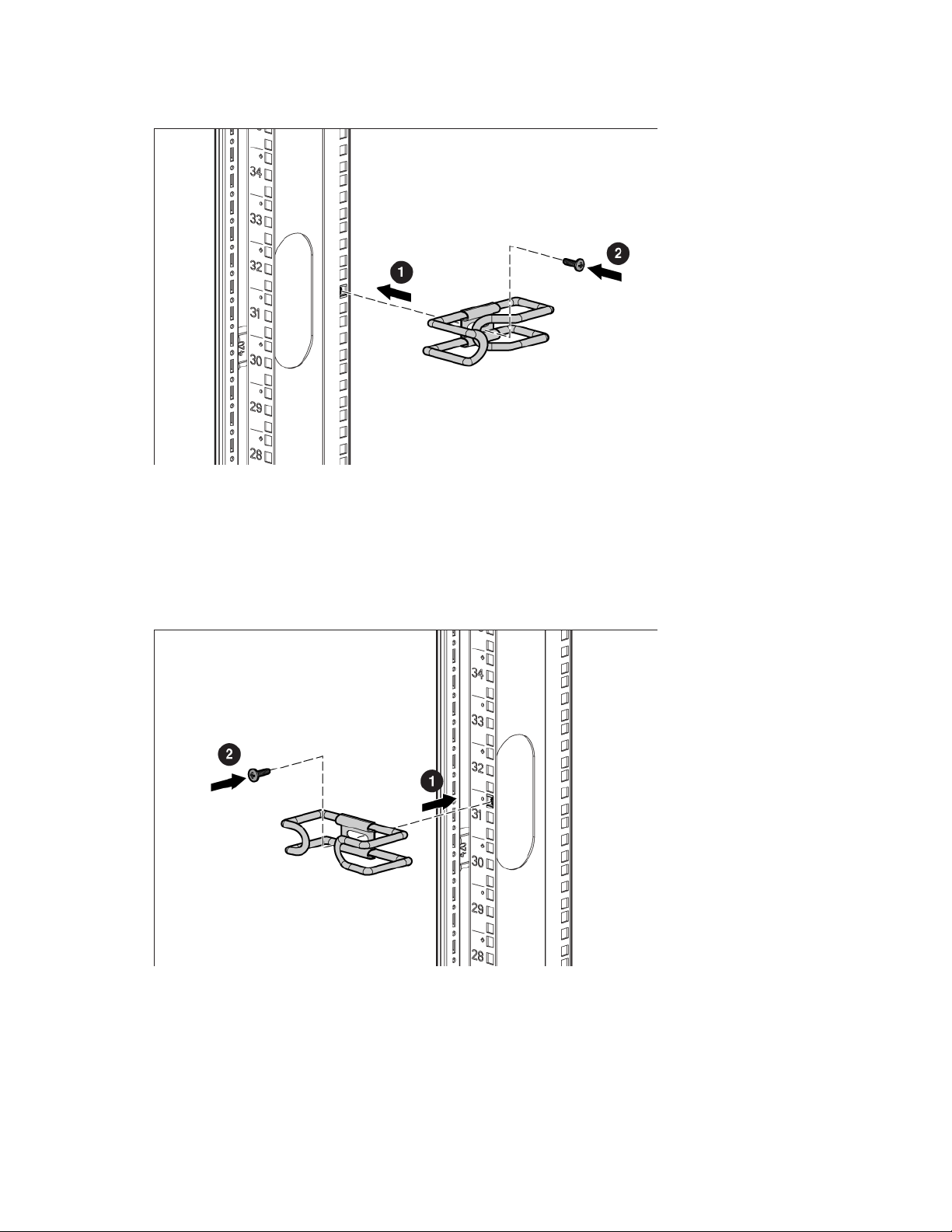
Using a T-25 Torx driver, insert one M6 x 16-mm Torx screw to secure the cable management D-ring
3.
bracket to the rack (2).
Side mount
1. Align the cable management D-ring bracket with the screw hole in the desired location on the side of
your rack (1).
2. Using a T-25 Torx driver, insert one M5.5 x10-mm Torx screw to secure the cable management D-ring
bracket to the rack (2).
Installing the cross-over bracket
1. Align the cross-over bracket with the appropriate screw holes in the desired location across the back of
the rack (1).
Cable Management Bracket kit 36
Page 37
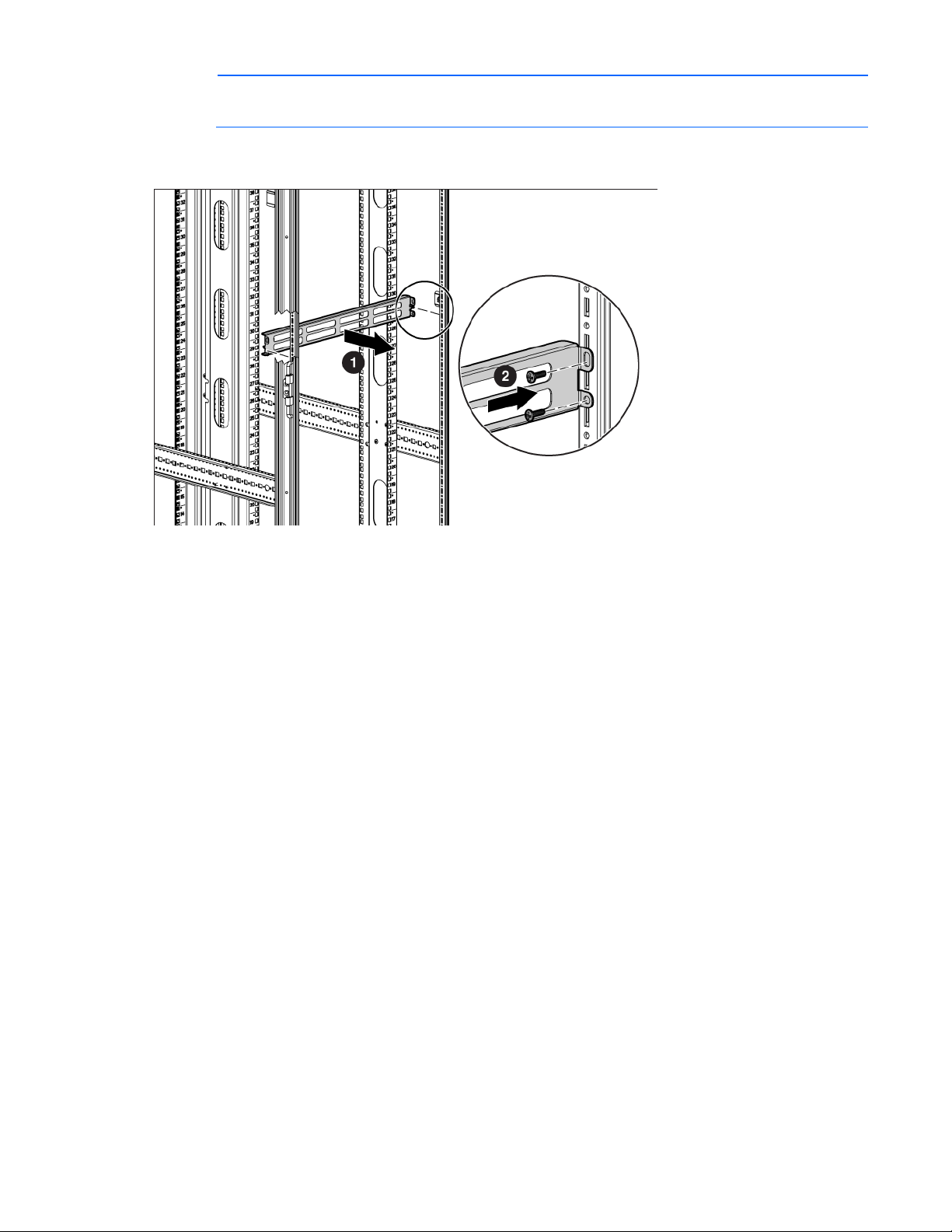
NOTE: The screw holes for the cross-over bracket are located on the side of the rear rack screw
column, towards the inside of the rack.
2. Using a T-25 Torx driver, insert two M5.5 x 10-mm Torx screws on either side of the cross-over bracket
and secure to the rack frame (2).
Cable Management Bracket kit 37
Page 38
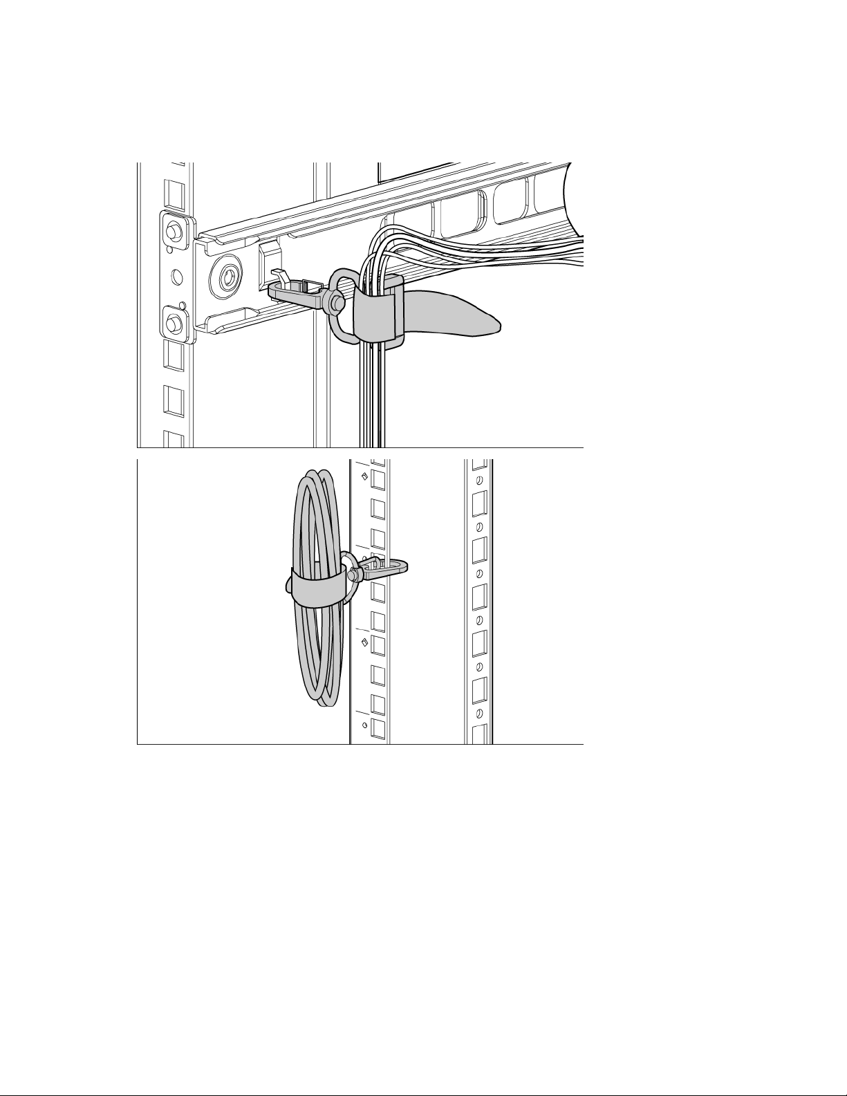
Installing the hook-and-loop cabling straps
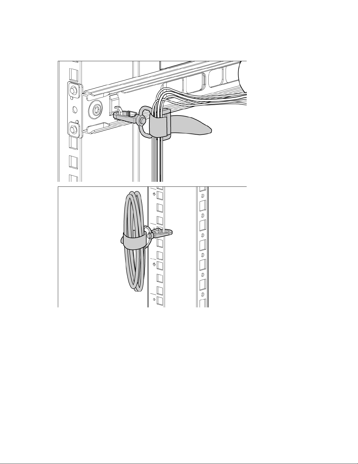
Attach the clip to the rack in any of the following positions, then route and secure your cables with the
hook-and-loop cabling straps.
Cable Management Bracket kit 38
Page 39
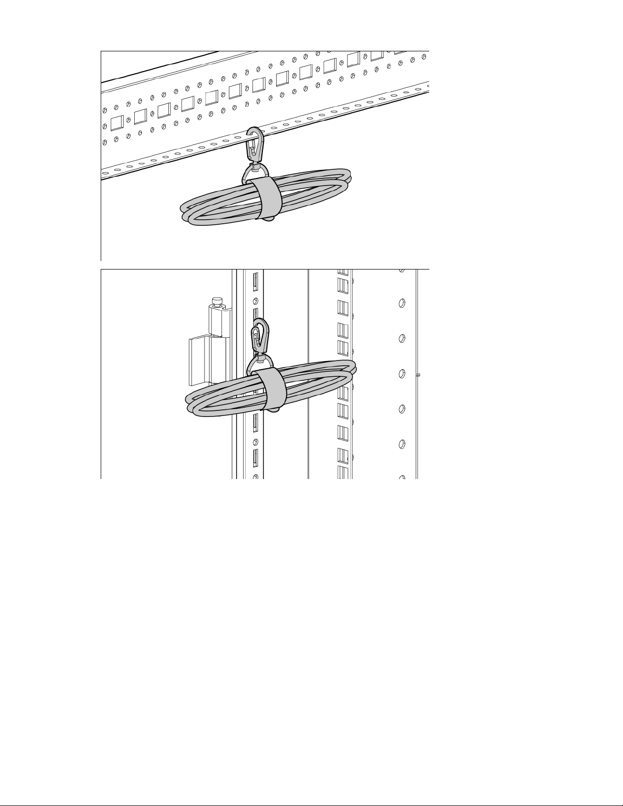
Installation is complete.
Cable Management Bracket kit 39
Page 40
Cable Management Tray kit
600-mm wide cable trough
8
600-mm wide wire trough
16
8
800-mm wide cable trough
1
800-mm wide wire trough
2
Trough cover
1
Inner tray trough
1
Outer tray trough
1
About this device
The HP Cable Management Tray kit enables you to attach cable management trays to the top of HP racks to
Kit contents
improve cable management.
Depending on which kit you order, this kit includes the following items:
HP 600-mm Rack Top Cable Management Tray
Item Quantity
Trough cover
—or—
HP 800-mm Rack Top Cable Management Tray
Item Quantity
—or—
HP Rack Top Cable Management Transfer Tray
Item Quantity
Extra hardware might be included for your convenience.
Required tool
You will need a T-30 Torx driver.
Cable Management Tray kit 40
Page 41
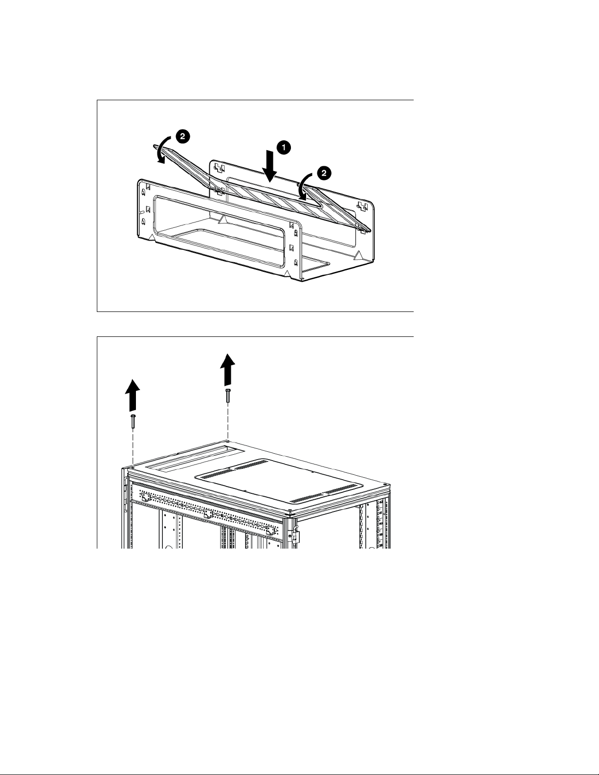
Installing the cable management tray
1. Attach the wire for the trough to the cable management tray.
2. Remove the two screws from the rack top.
Cable Management Tray kit 41
Page 42
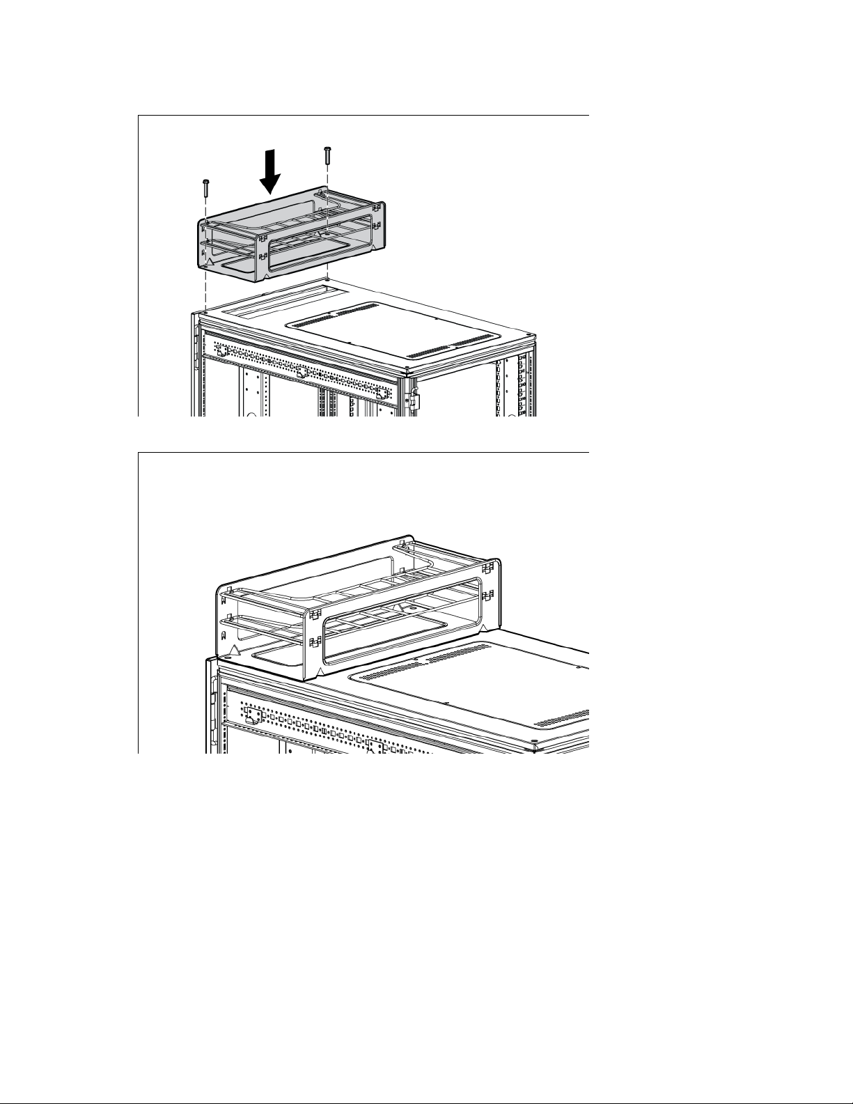
Install the cable management tray on top of the rack, using the same two screws you removed in step
3.
2.
4. Route the cables through the cable management tray.
Cable Management Tray kit 42
Page 43
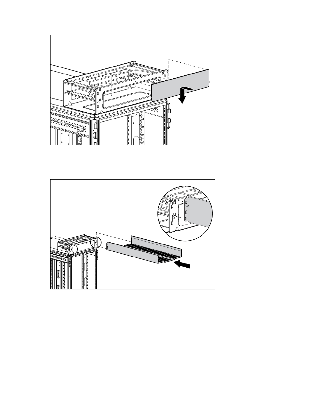
Hook and slide the cover into place.
5.
Installing the cable management transfer tray
1. Attach the cable management outer tray to the cable management tray.
Cable Management Tray kit 43
Page 44
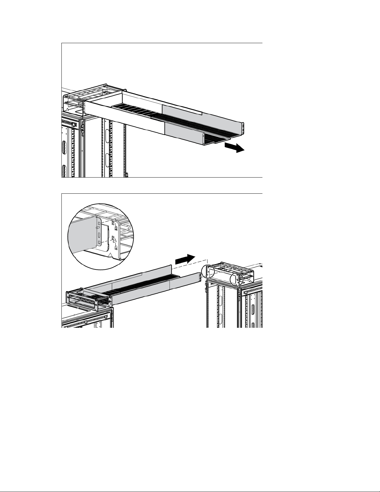
Slide the inner tray into the outer tray, and adjust them to the desired length.
2.
3. Attach the cable management inner tray to the cable management tray.
Cable Management Tray kit 44
Page 45
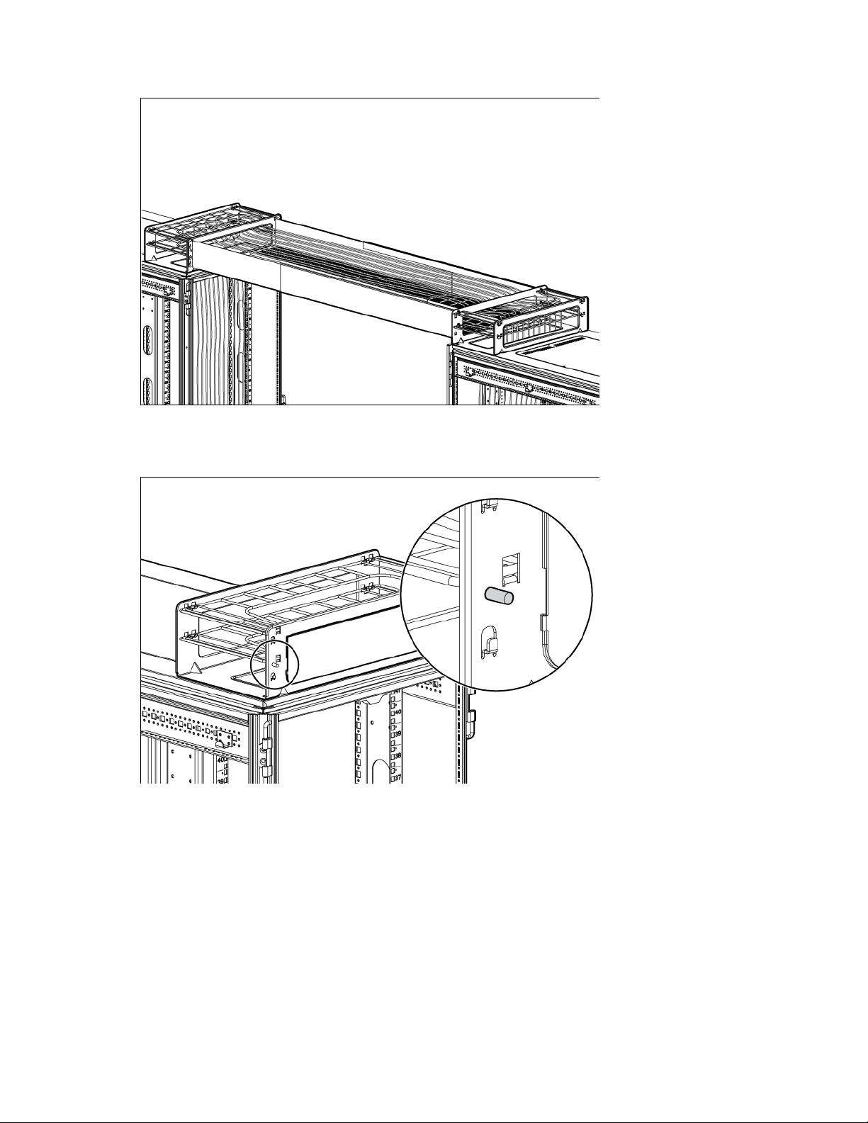
Route the cables through the cable management tray.
4.
Ground bonding stud location
Cable Management Tray kit 45
Page 46
Front Door kit
Front door
1
Keys
2
Hinge brackets
2
Lock catches
2
About this device
The Enterprise Series Front Door kit is a replacement kit that is compatible with HP Advanced Series Racks
and Enterprise Series Racks.
Kit contents
Item Quantity
This kit might contain extra hardware for your convenience.
Required tools
The following tools are required for installation:
• T-25 Torx driver
• Phillips screwdriver
Front Door kit 46
Page 47
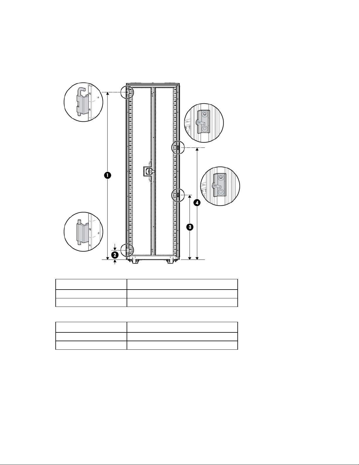
Installing the hinge brackets and lock catches
1
1856 mm (73.1 in)
2
98.5 mm (3.9 in)
3
698.5 mm (27.5 in)
4
1256.5 mm (49.5 in)
The following tables indicate where the hinge brackets and lock catches are to be mounted in a 42U front
door installation. The distance is measured from the bottom of the rack to an indicated hinge bracket or lock
catch fastening hole.
Hinge bracket mounting distance from the bottom of the rack
Position number 42U
Lock catch mounting distance from the bottom of the rack
Position number 42U
Front Door kit 47
Page 48
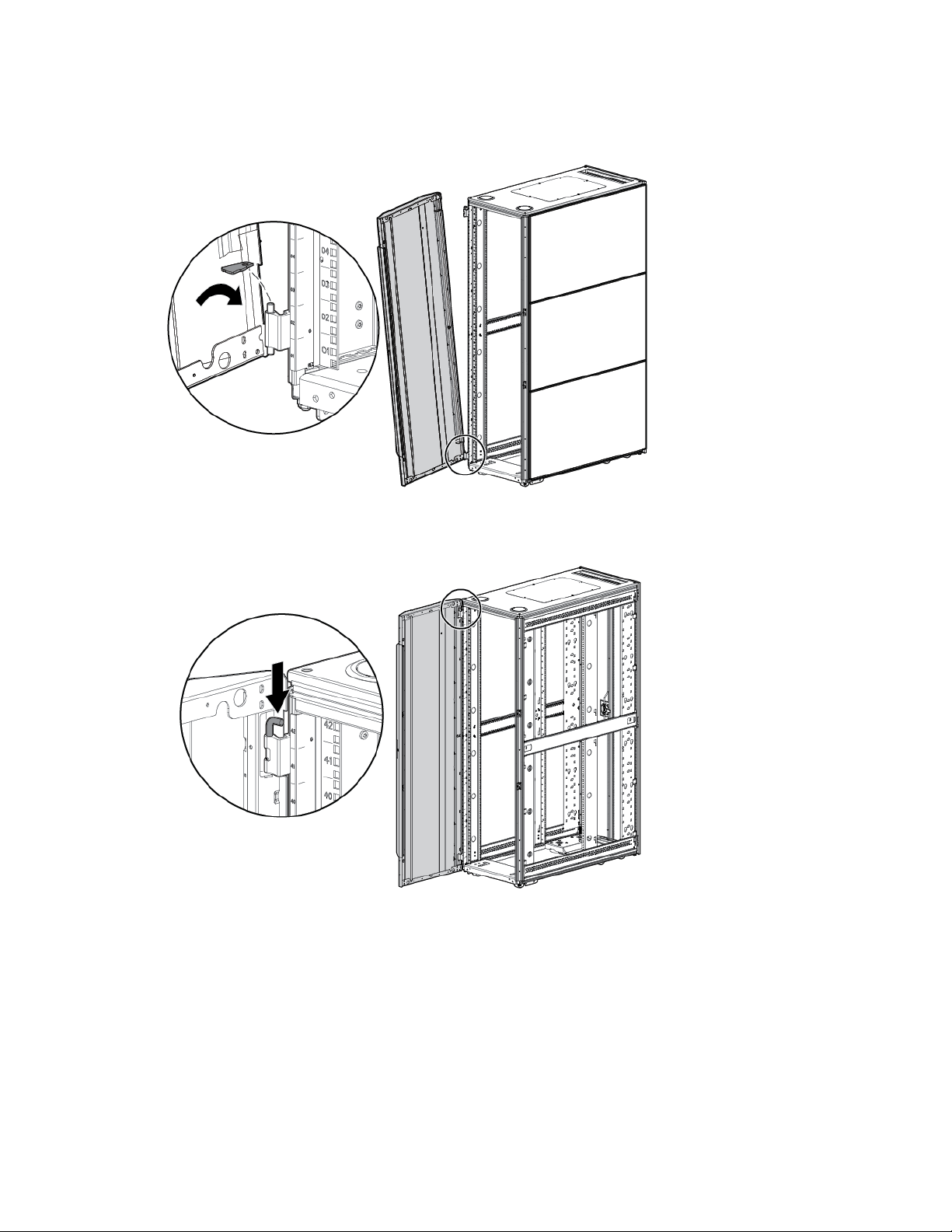
Installing the front door
1. Slide the bottom door hinge onto the hinge bracket on the rack frame.
2. Lift the top hinge pin up, and then slide the upper door hinge into place.
3. To secure the front door to the rack, release the top hinge pin.
4. Close the front door.
Installation is complete.
Front Door kit 48
Page 49

Ground Bonding kit
15.24-cm (6-in) grounding straps
3
36.83-cm (14.5-in) grounding straps
3
(with a connector on one end)
6
(with a connector on one end)
6
M8 nut
12
Internal serrated lock washer
11
M8 x 20 hex head screw
1
Self-tapping 5.5 x 10 screw
10
6.2 Paint cutter washer
1
8.4 Paint cutter washer
1
M6 x 10 low HD cap screw
1
About this device
The Ground Bonding kit reduces the electromagnetic emissions outside of the HP Advanced Series Racks and
Enterprise Series Racks. These emissions are produced during normal operation of the electronic components
within the rack. Typically, rack-mounted equipment must meet class A emissions levels, but you might want to
reduce these levels even further. Use this kit to tie all the conductive structural components together with
conductive cables, and then attach the kit to a ground bonding point on the AC power distribution device of
the rack or the building ground.
Kit contents
Item Quantity
15.24-cm (6-in) grounding straps
36.83-cm (14.5-in) grounding straps
This kit might contain extra hardware for your convenience.
Required tools
The following tools are required for installation:
• T-25 Torx driver
• M8 socket
Installing the ground bonding rack option kit
Attach the appropriate grounding straps to the following locations.
From the system chassis to the front door (without a grounding lug):
1. Remove the rack front door.
Ground Bonding kit 49
Page 50
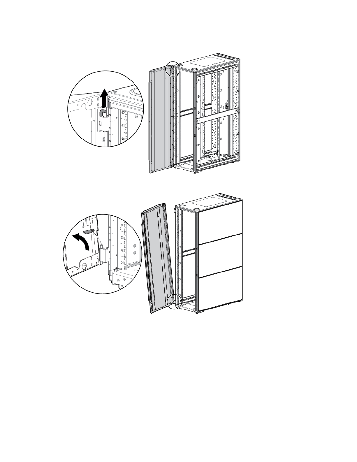
Unlock and open the front door.
a.
b. Lift the top hinge pin up, and then tilt the door away from the rack.
c. Lift the door up and out of the bottom hinge.
2. Insert an M6 T-25 Torx screw through one end of a 15.24-cm (6-inch) grounding strap which is attached
to the outside of the frame, and then insert the screw in the second hole below the upper front door
hinge. Tighten the screw.
3. Install the rack front door.
Ground Bonding kit 50
Page 51
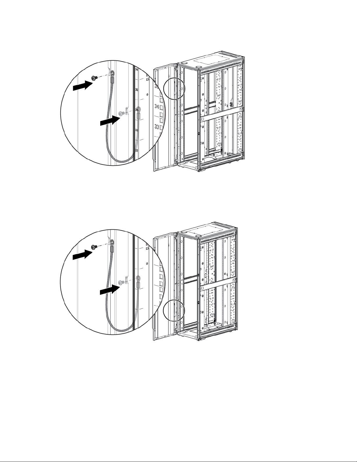
Insert a T-25 Torx screw through the other end of the same grounding strap, and then insert the screw
4.
in the hole on the rack front door. Tighten the screw.
For front doors (with a grounding lug):
1. Insert a T-25 Torx screw through the other grounding strap end and secure it to the front door.
2. Place an M8 internal serrated lock washer and an M8 hex nut over the grounding lug on the front door,
and then tighten the washer.
From the system chassis rail to the right rear door:
1. Insert a T-25 Torx screw through the end of a 36.83-cm (14.5-inch) grounding strap, and then secure
the screw to the system chassis rail.
2. Place the other end of the same grounding strap over the grounding lug on the right rear door.
3. Place an M8 internal serrated lock washer and an M8 hex nut over the grounding lug on the right rear
door, and then tighten the washer.
Ground Bonding kit 51
Page 52
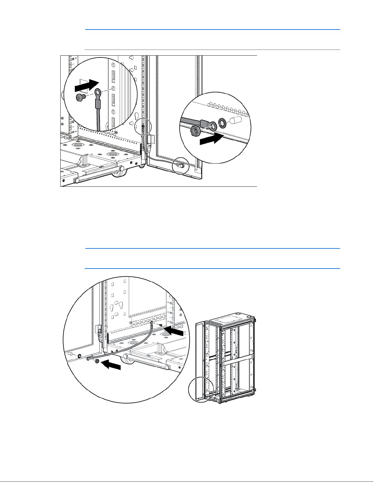
IMPORTANT: The location of the welding stud on your model may vary.
From the system chassis rail to the left rear door:
1. Insert a T-25 Torx screw through the end of a 36.83-cm (14.5-inch) grounding strap, and then secure
the screw to the system chassis rail.
2. Place the other end of the grounding strap over the grounding lug on the left rear door.
3. Place an M8 internal serrated lock washer and an M8 hex nut over the grounding lug on the left rear
door, and then tighten the washer.
IMPORTANT: The location of the welding stud on your model may vary.
From the system chassis rail to the rack top:
1. Insert a T-25 Torx screw through one end of a 15.24-cm (6-inch) grounding strap, and then secure the
screw to the system chassis rail.
Ground Bonding kit 52
Page 53
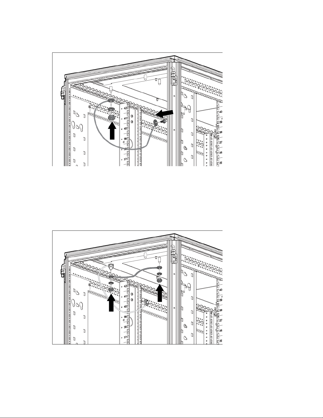
Place the other end of the same grounding strap over the grounding lug on the rack top.
2.
3. Place an M8 internal serrated lock washer and an M8 hex nut over the grounding lug on the rack top,
and then tighten the washer.
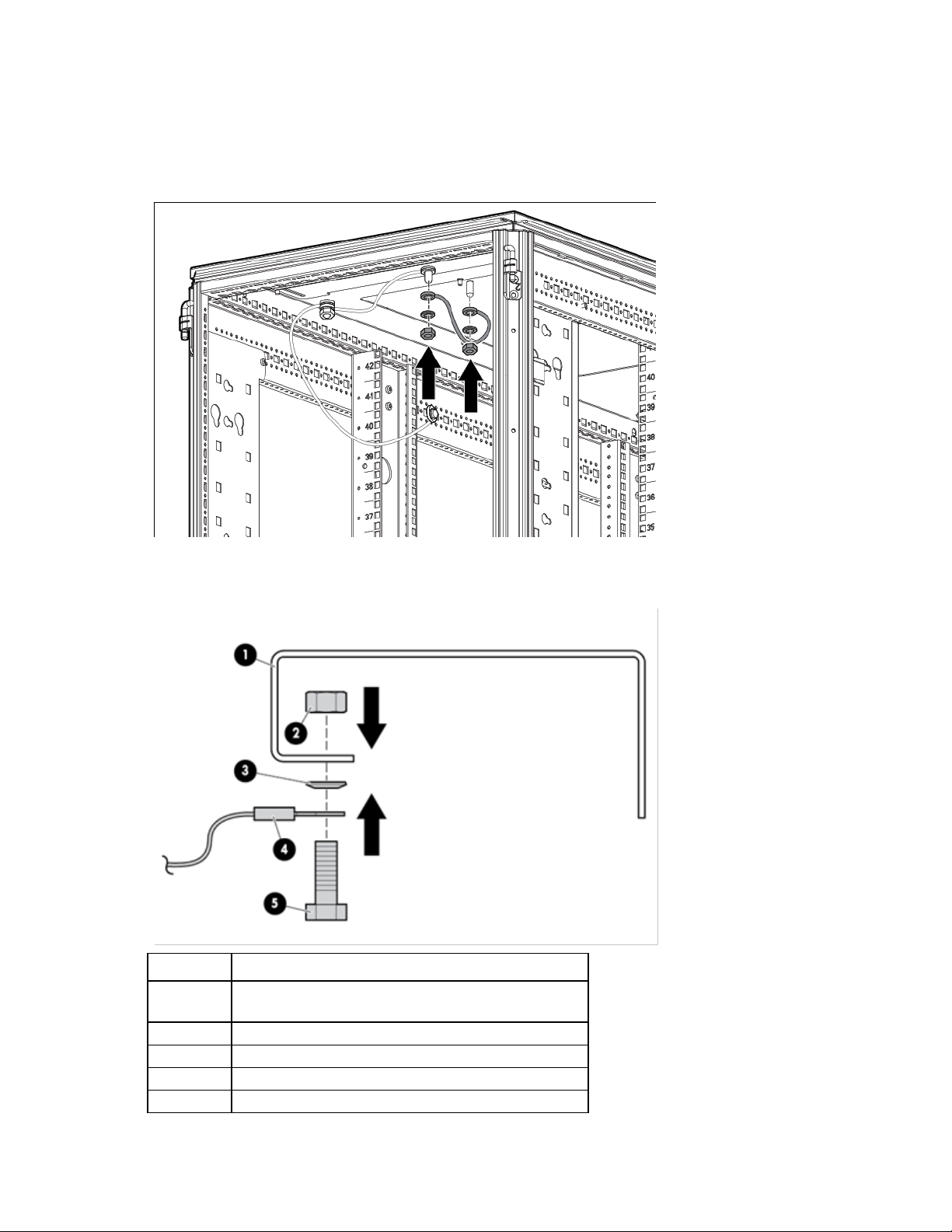
From the grounding lug on the rack top to the grounding lug on the perforated panel:
1. Place one end of a 36.83-cm (14.5-inch) grounding strap over the grounding lug on the rack top.
2. Place an M8 internal serrated lock washer and an M8 hex nut over the grounding lug on the rack top,
and then tighten the washer.
3. Place the other end of the same grounding strap over the grounding lug on the perforated panel.
4. Place an M8 internal serrated lock washer and an M8 hex nut over the grounding lug on the perforated
panel, and then tighten the washer.
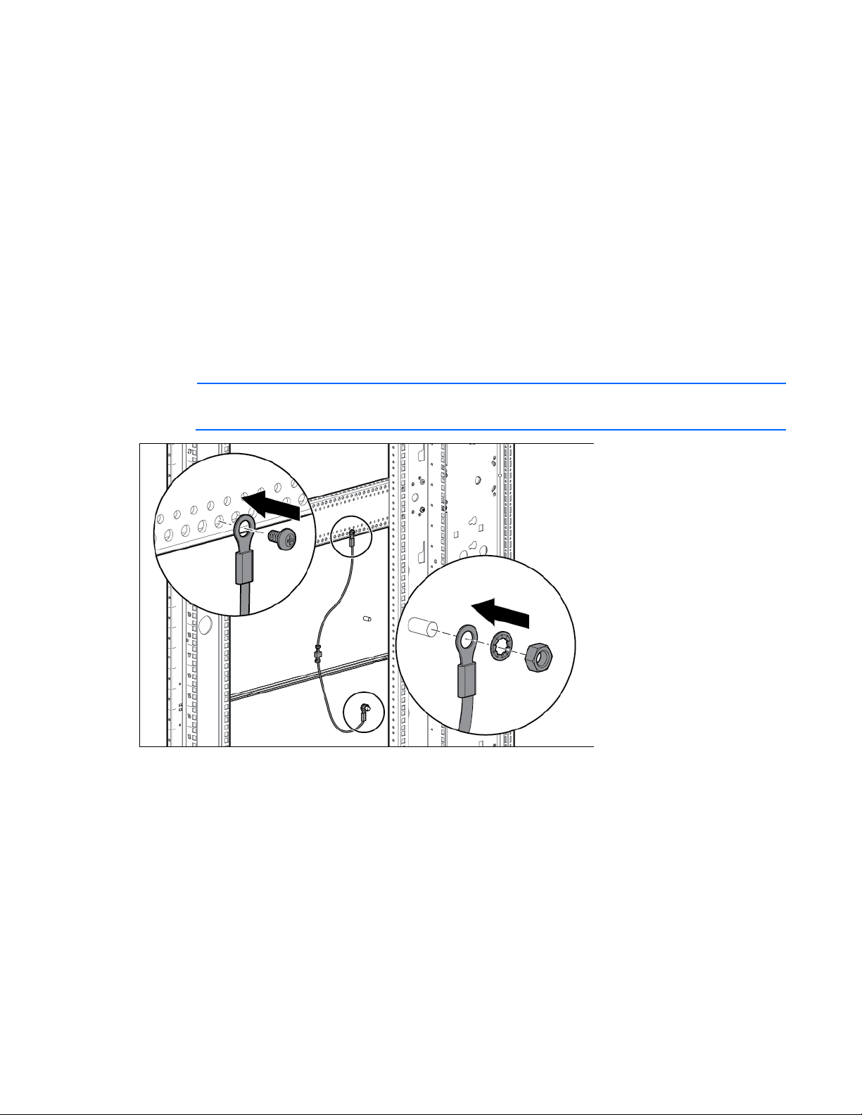
From the grounding lug on the perforated panel or fan kit to the grounding lug on the egress slot:
1. Place one end of a 15.24-cm (6-inch) grounding strap over the grounding lug on the perforated panel
or fan kit.
Ground Bonding kit 53
Page 54
Place an M8 internal serrated lock washer and an M8 hex nut over the grounding lug on the perforated
48.26-cm (19-inch) mounting rail (the mounting hole is
2
M8 hex nut
3
M8 Belleville toothed washer
4
Facility ground (not included with this kit)
5
M8 x 20 bolt
2.
panel or fan kit, and then tighten the washer.
3. Place the other end of the same grounding strap over the grounding lug on the egress slot.
4. Place an M8 internal serrated lock washer and an M8 hex nut over the grounding lug on the egress slot,
and then tighten the washer.
From the rack to a building facility:
For more information, contact your building supervisor. The following figure illustrates parts for this step.
Reference Item
1
located at the top or bottom of the rail)
Ground Bonding kit 54
Page 55
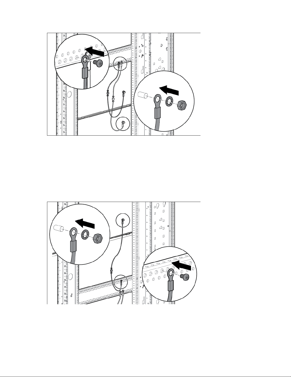
Installing the ground bonding rack option kit on side panels
From the middle system chassis rail to the bottom side panel:
1. Connect a 36.83-cm (14.5-inch) and a 15.24-cm (6-inch) grounding strap with connectors together.
2. Insert a T-25 Torx screw through the end of the 36.83-cm (14.5-inch) grounding strap, and then secure
the screw to the middle system chassis rail.
3. Place the end of the 15.24-cm (6-inch) grounding strap over the grounding lug on the bottom side
panel.
4. Place an M8 internal serrated lock washer and an M8 hex nut over the grounding lug on the bottom
side panel, and then tighten the washer.
5. Repeat steps 1 through 4 for the other bottom side panel.
IMPORTANT: The location of the welding stud on your model may vary.
From the middle system chassis rail to the middle side panel:
1. Connect a 36.83-cm (14.5-inch) and a 15.24-cm (6-inch) grounding strap with connectors together.
2. Insert a T-25 Torx screw through the end of the 36.83-cm (14.5-inch) grounding strap, and then secure
the screw to the middle system chassis rail.
3. Place the end of the 15.24 (6-inch) grounding strap over the grounding lug on the middle side panel.
4. Place an M8 internal serrated lock washer and an M8 hex nut over the grounding lug on the middle
side panel, and then tighten the washer.
Ground Bonding kit 55
Page 56
Repeat steps 1 through 4 for the other middle side panel.
5.
From the middle system chassis rail to the top side panel:
1. Connect a 36.83-cm (14.5-inch) and a 15.24-cm (6-inch) grounding strap with connectors together.
2. Insert a T-25 Torx screw through the end of a 36.83-cm (14.5-inch) grounding strap, and then secure
the screw to the middle system chassis rail.
3. Place the end of the 15.24-cm (6-inch) grounding strap over the grounding lug on the top side panel.
4. Place an M8 internal serrated lock washer and an M8 hex nut over the grounding lug on the top side
panel, and then tighten the washer.
5. Repeat steps 1 through 4 for the other top side panel.
Ground Bonding kit 56
Page 57
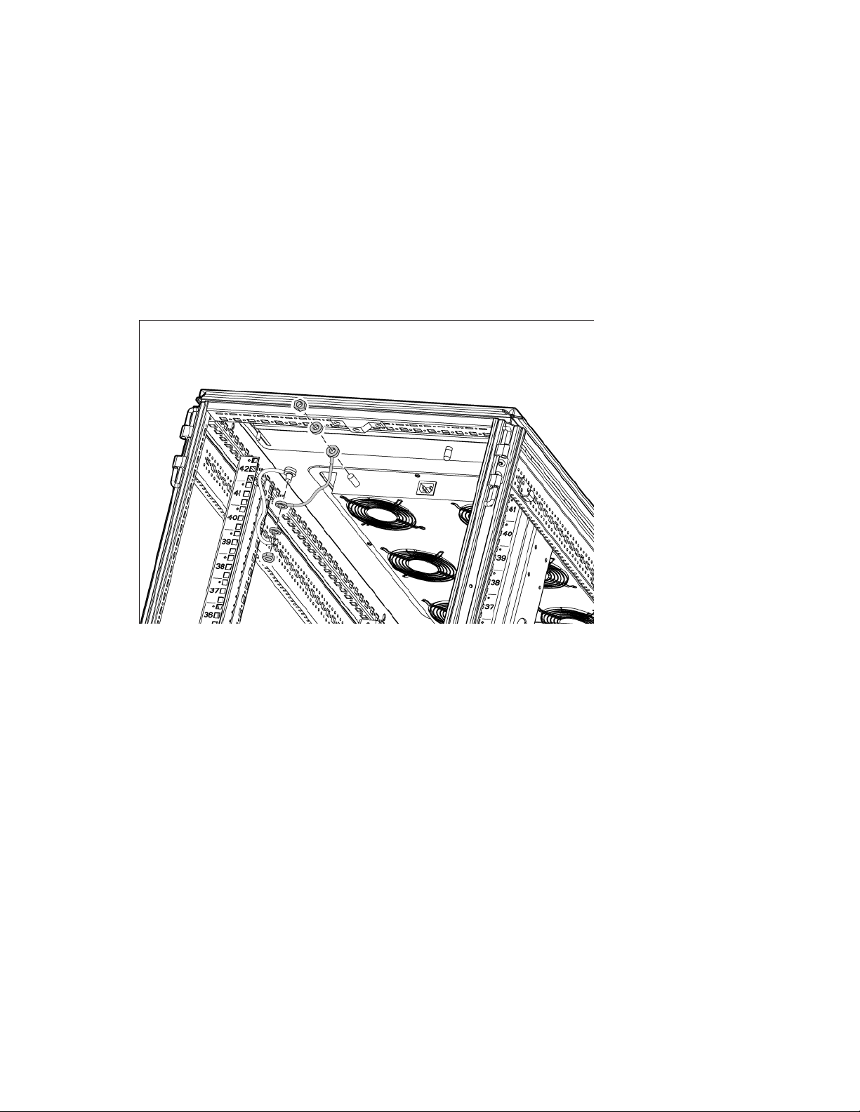
Installing the ground bonding rack option kit on fan kits
From the grounding lug on the rack top to the grounding lug on the fan kit:
1. Place one end of a 15.24-cm (6-inch) grounding strap over the grounding lug on the rack top.
2. Place an M8 internal serrated lock washer and an M8 hex nut over the grounding lug on the rack top,
and then tighten the washer.
3. Place the other end of the same grounding strap over the grounding lug on the perforated panel.
4. Place an M8 internal serrated lock washer and an M8 hex nut over the grounding lug on the perforated
panel, and then tighten the washer.
From the grounding lug on the fan kit to the grounding lug on the egress slot:
1. Place one end of a 36.83-cm (14.5-inch) grounding strap over the grounding lug on the fan kit.
2. Place an M8 internal serrated lock washer and an M8 hex nut over the grounding lug on the fan kit, and
then tighten the washer.
3. Place the other end of the same grounding strap over the grounding lug on the egress slot.
Ground Bonding kit 57
Page 58
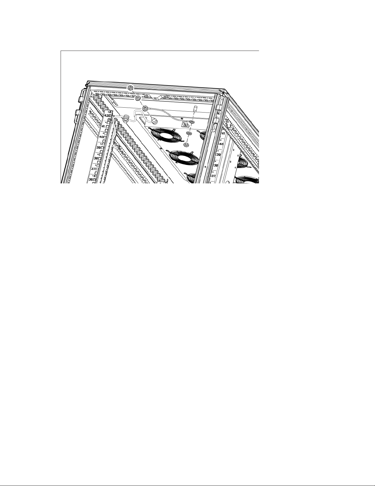
Place an M8 internal serrated lock washer and an M8 hex nut over the grounding lug on the egress slot,
4.
and then tighten the washer.
Ground Bonding kit 58
Page 59
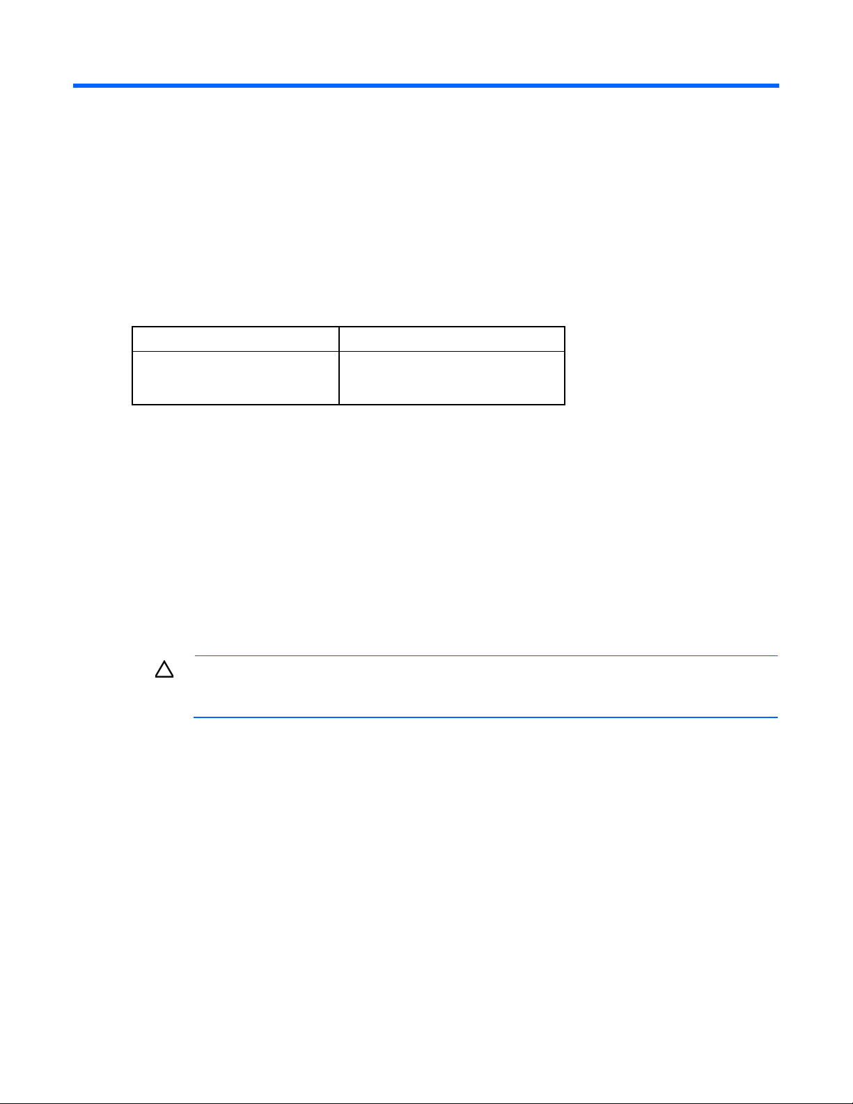
Filler Panel kit
1U Filler panels
10
About this device
The Filler Panel kit enables you to cover open areas of the HP Advanced Series Racks and Enterprise Series
Racks to better control airflow.
Kit contents
Item Quantity
1U Filler panels
—or—
This kit might contain extra hardware for your convenience.
100
Required tools
No tools are required for this procedure.
Installing the filler panel
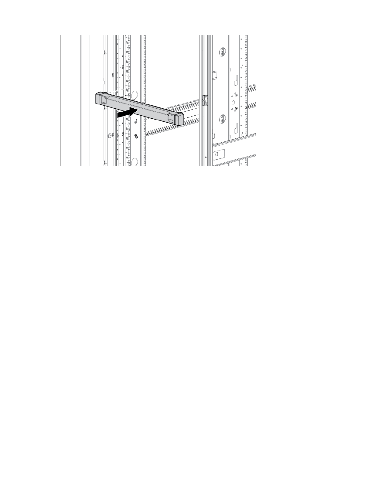
1. Position the filler panel in the desired rack location.
2. Snap the filler panel into place.
CAUTION: Always use filler panels to fill all remaining empty front panel U-spaces in the rack.
This arrangement ensures proper airflow. Using a rack without filler panels results in improper
cooling, which can lead to thermal damage.
Filler Panel kit 59
Page 60
Filler Panel kit 60
Page 61
Heavy Duty Stabilizer kit
1
Heavy duty stabilizer feet
2
M8 x 16-mm bolt
8
M8 x 30-mm bolt
2
M8 flat washer
10
About this device
The Heavy Duty Stabilizer kit provides stability and support and prevents possible tipping when you install,
remove, or access equipment within the HP Advanced Series Racks and Enterprise Series Racks.
If you have a stand-alone rack with a single rack-mountable component that exceeds 99.8 kg (220 lb) or if
you have three or fewer bayed racks with a single rack-mountable component that exceeds 99.8 kg (220 lb),
you must use the heavy duty stabilizer.
Kit contents
Item Quantity
Heavy duty front stabilizer mount
This kit might contain extra hardware for your convenience.
Required tools
The following tools are required for installation:
• Ratchet with sockets
• Adjustable wrench
Installing the rack stabilizer option kit
1. Install the front stabilizer mount.
a. Align the front stabilizer mount to the mounting holes on the rack front caster plate.
Heavy Duty Stabilizer kit 61
Page 62
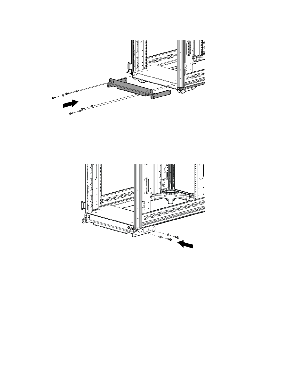
Insert and partially tighten four M8 x16-mm bolts with washers, securing the front stabilizer mount
b.
to the front caster plate.
c. Insert and partially tighten two M8 x16-mm bolts with washers on each side of the caster plate skirt,
securing the front stabilizer mount to the front caster plate.
d. Tighten the bolts from step b.
e. Tighten the bolts from step c.
Heavy Duty Stabilizer kit 62
Page 63
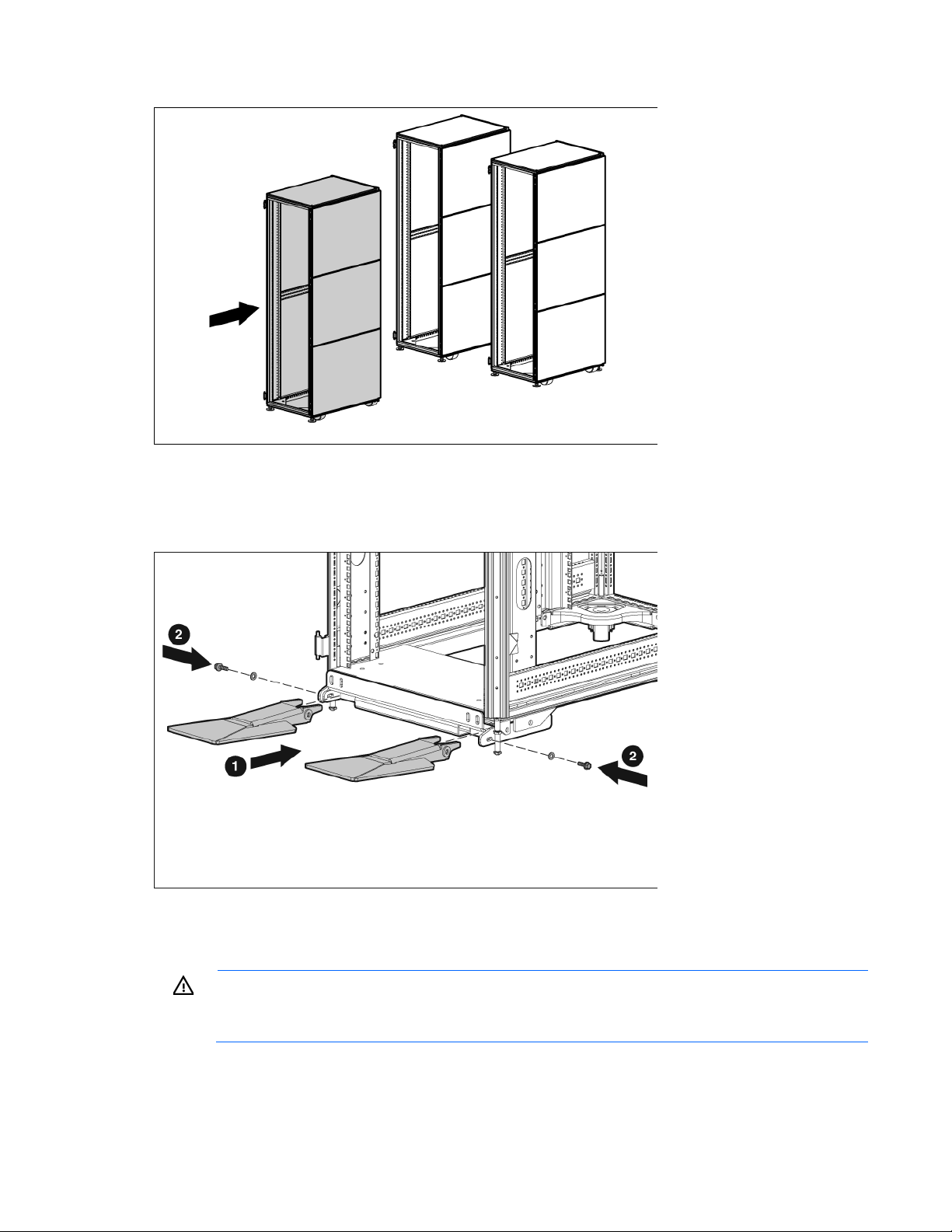
Slide the rack into its final location.
2.
3. Raise the rack by lowering the leveling feet, raising the casters approximately 6.4 mm (0.25 in) off the
floor.
4. Install one stabilizer foot on each side of the front stabilizer mount (1) by inserting and partially
tightening one M8 x 30-mm bolt and washer on each foot (2).
5. Fully seat each stabilizer foot to the front stabilizer mount, and tighten the bolts from step 4.
6. Lower the rack so that the full weight of the rack rests on the rear leveling feet and the front stabilizer
feet.
WARNING: To reduce the risk of personal injury or damage to the equipment, be sure that:
• The rear leveling feet are extended to the floor.
• The full weight of the rack rests on the rear leveling feet and front stabilizer feet.
Installation is complete.
Heavy Duty Stabilizer kit 63
Page 64
1/4 Turn Hook and Loop Cabling Strap kit
PK
10
PK
100
About this device
The Hook-and-Loop Cabling Strap Clip kit enables you to add hook-and-loop cabling strap clips to manage
your cable configurations for the HP Advanced Series Racks and Enterprise Series Racks. The cabling straps
attach to the rear cable management bracket.
Kit contents
Item Quantity
1/4 Turn Hook and Loop Strap 10
1/4 Turn Hook and Loop Strap 100
This kit might contain extra hardware for your convenience.
Required tools
No tools are required for this procedure.
Installing the hook-and-loop cabling strap clips
1. Route and secure your cables with the hook-and-loop cabling strap clips.
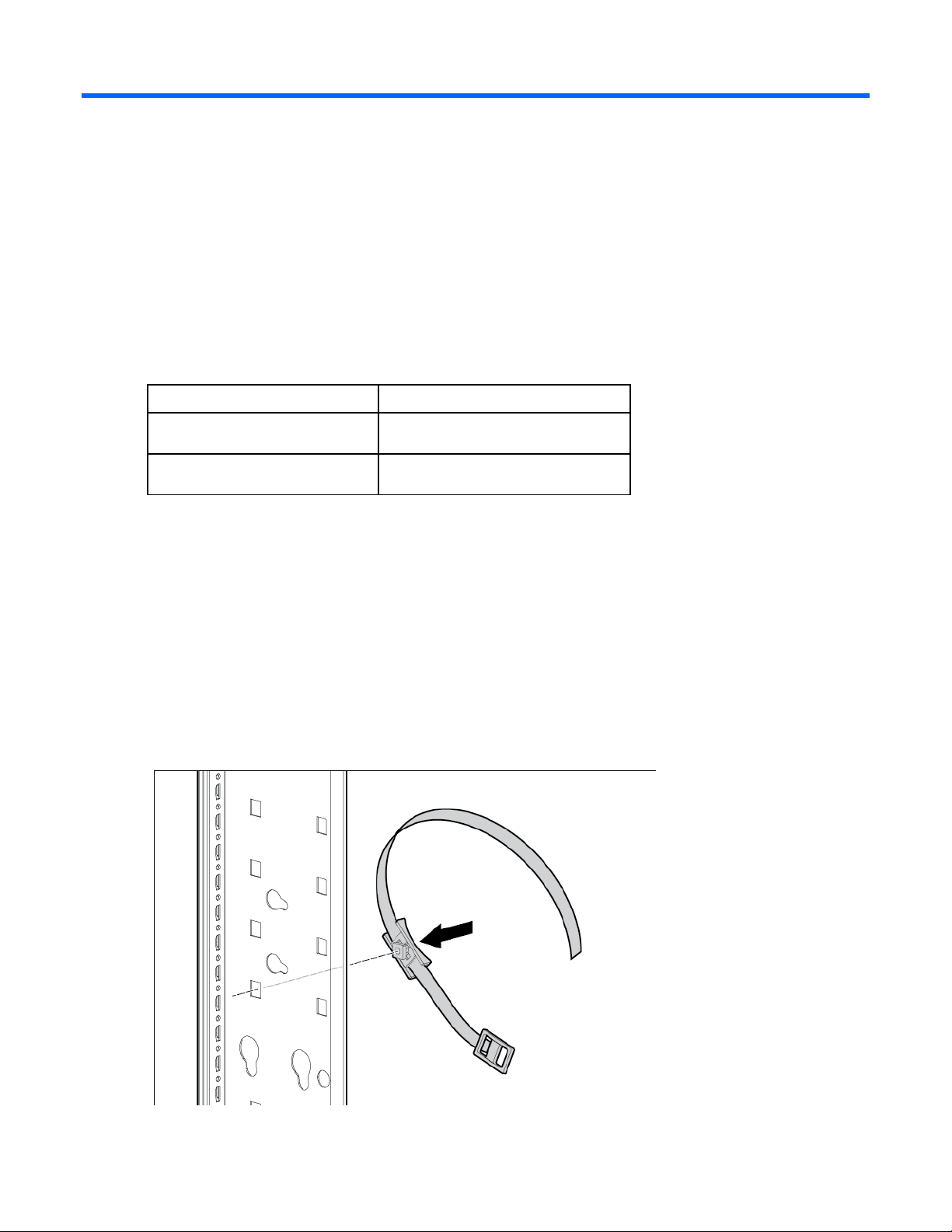
2. Turn the hook-and-loop cabling strap clip at a slight angle to align the square nut with the square hole
on the rack.
1/4 Turn Hook and Loop Cabling Strap kit 64
Page 65
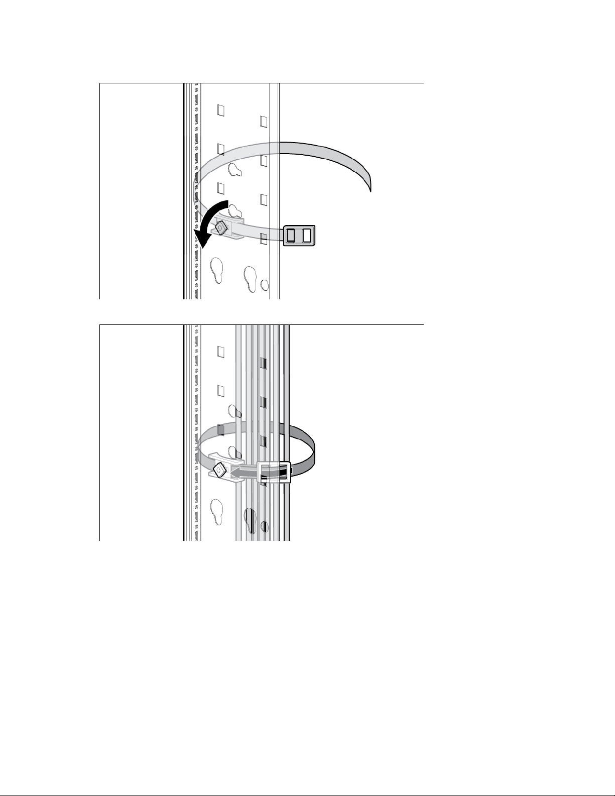
Insert the square nut into the square hole on the rack, and then turn it at a 45 degree angle to lock it into
3.
place.
4. Bundle rack cables as required.
Installation is complete.
1/4 Turn Hook and Loop Cabling Strap kit 65
Page 66
Hook-and-Loop Cabling Strap Clip kit
cabling strap clip
20
cabling strap clip
20
cabling strap clip
10
About this device
The HP Hook-and-Loop Cabling Strap Clip kit enables you to add hook-and-loop cabling strap clips to
manage your cable configurations.
Kit contents
Item Quantity
12.7-cm (5-in) hook-and-loop
20.3-cm (8-in) hook-and-loop
30.5-cm (12-in) hook-and-loop
This kit might contain extra hardware for your convenience.
Required tools
No tools are required for this procedure.
Hook-and-Loop Cabling Strap Clip kit 66
Page 67
Installing the hook-and-loop cabling strap clips
Route and secure your cables with the hook-and-loop cabling strap clips.
Hook-and-Loop Cabling Strap Clip kit 67
Page 68
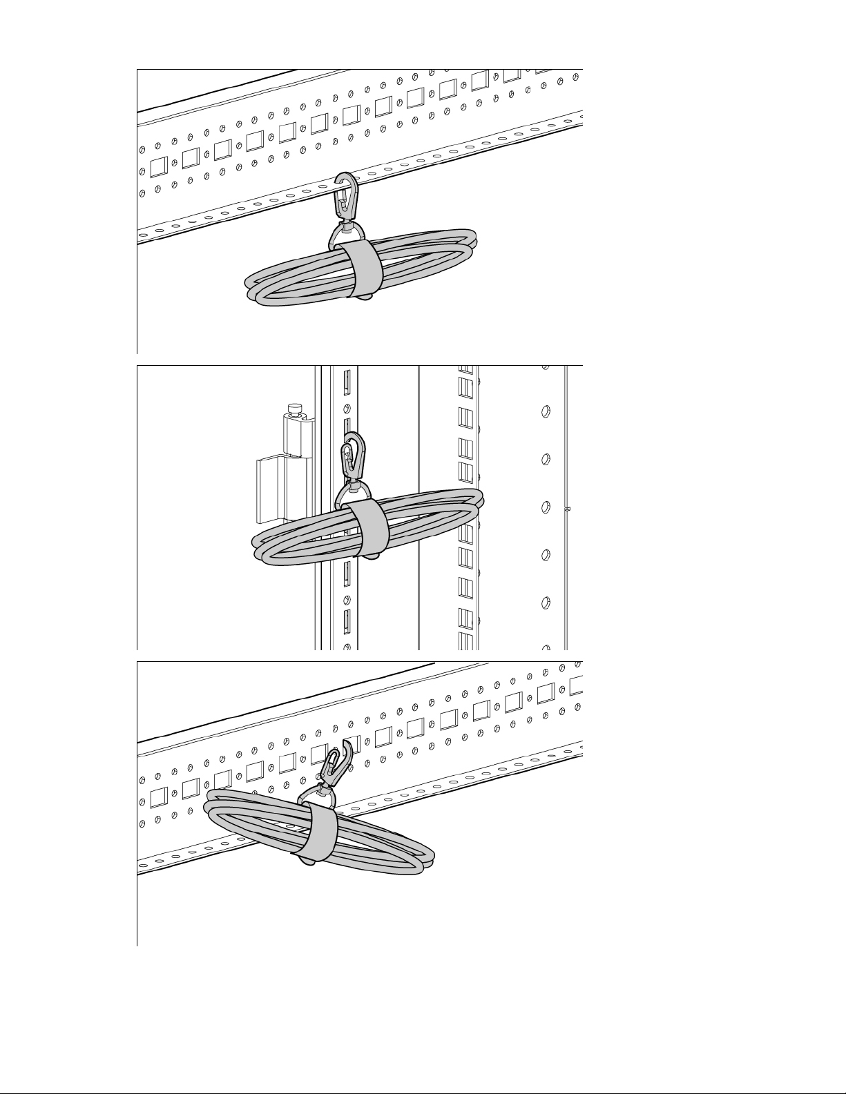
Hook-and-Loop Cabling Strap Clip kit 68
Page 69
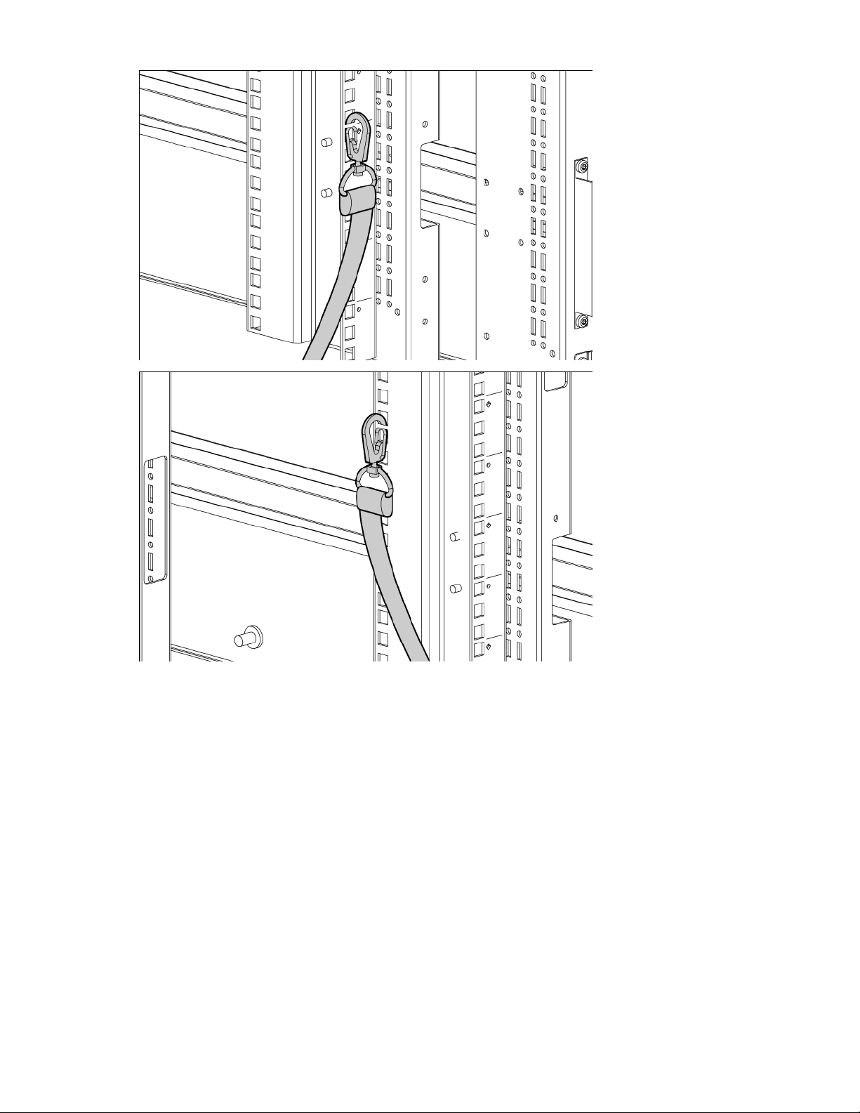
Installation is complete.
Hook-and-Loop Cabling Strap Clip kit 69
Page 70
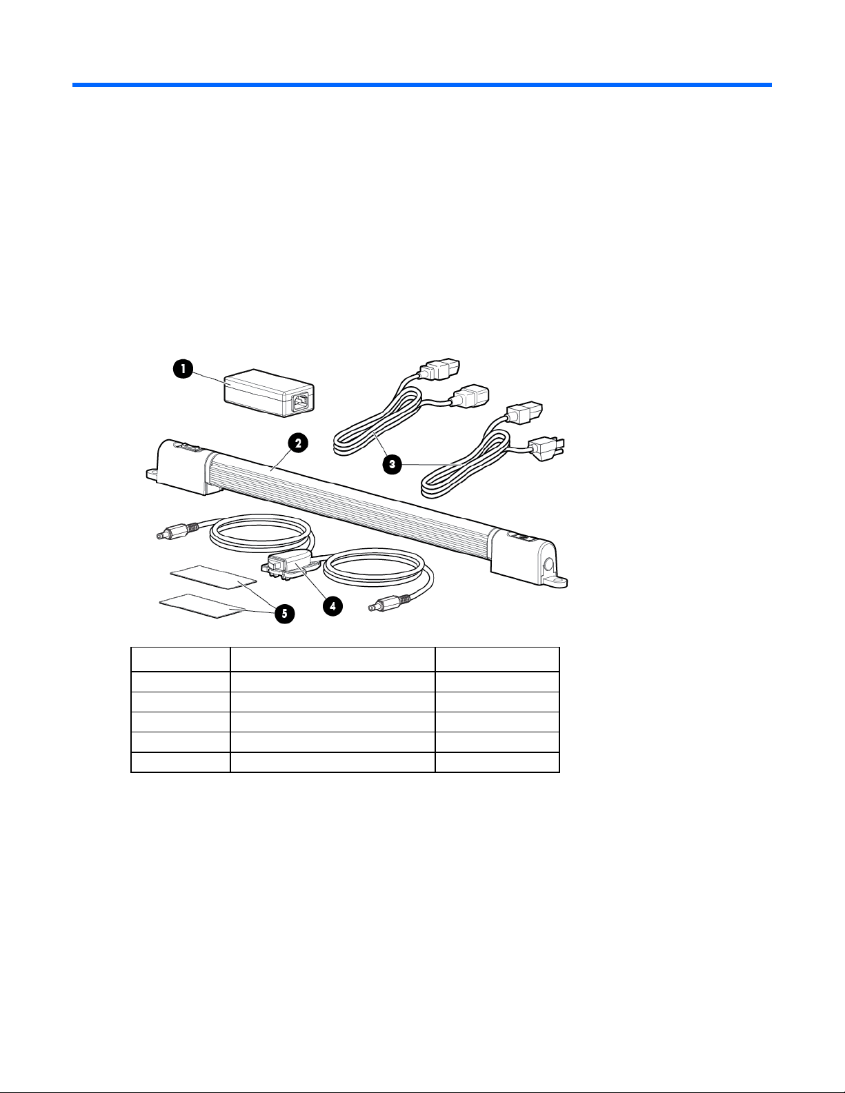
LED Light kit
1
Power adapter
1 2 LED light
1 3 Power cord (two pieces)
2
4
LED light switch
1 5 Hook-and-Loop tape, 1.97" x 3.94"
2
About this device
The LED Light kit enables you to add a light to the rack.
Kit contents
If any of the following items are missing or damaged, contact your HP authorized reseller.
Item Description Quantity
Extra hardware might be included for your convenience.
LED Light kit 70
Page 71
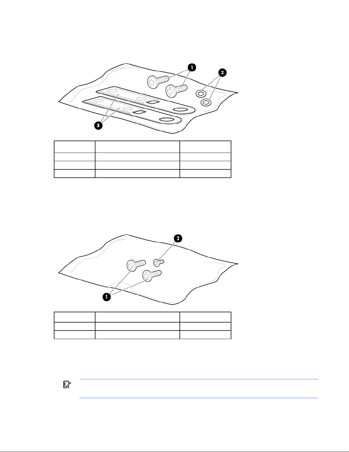
LED Light mounting hardware kit contents
1
Screw, 5.5x10, self-tapping
2 2 Washer, M6 plain
2 3 Mounting plate
2
1
Screw, 5.5x10, self-tapping
2
2
Screw, PT4 x8, Z/P, self-tapping
1
Instructions shown are general guidelines. The HP LED Light kit installation can be
If any of the following items are missing or damaged, contact your HP authorized reseller.
Item Description Quantity
Extra hardware might be included for your convenience.
LED light switch mounting hardware kit contents
If any of the following items are missing or damaged, contact your HP authorized reseller.
Item Description Quantity
Extra hardware might be included for your convenience.
Installing the LED Light kit
IMPORTANT:
ambidextrous and adjustable to accommodate varying rack configurations.
LED Light kit 71
Page 72
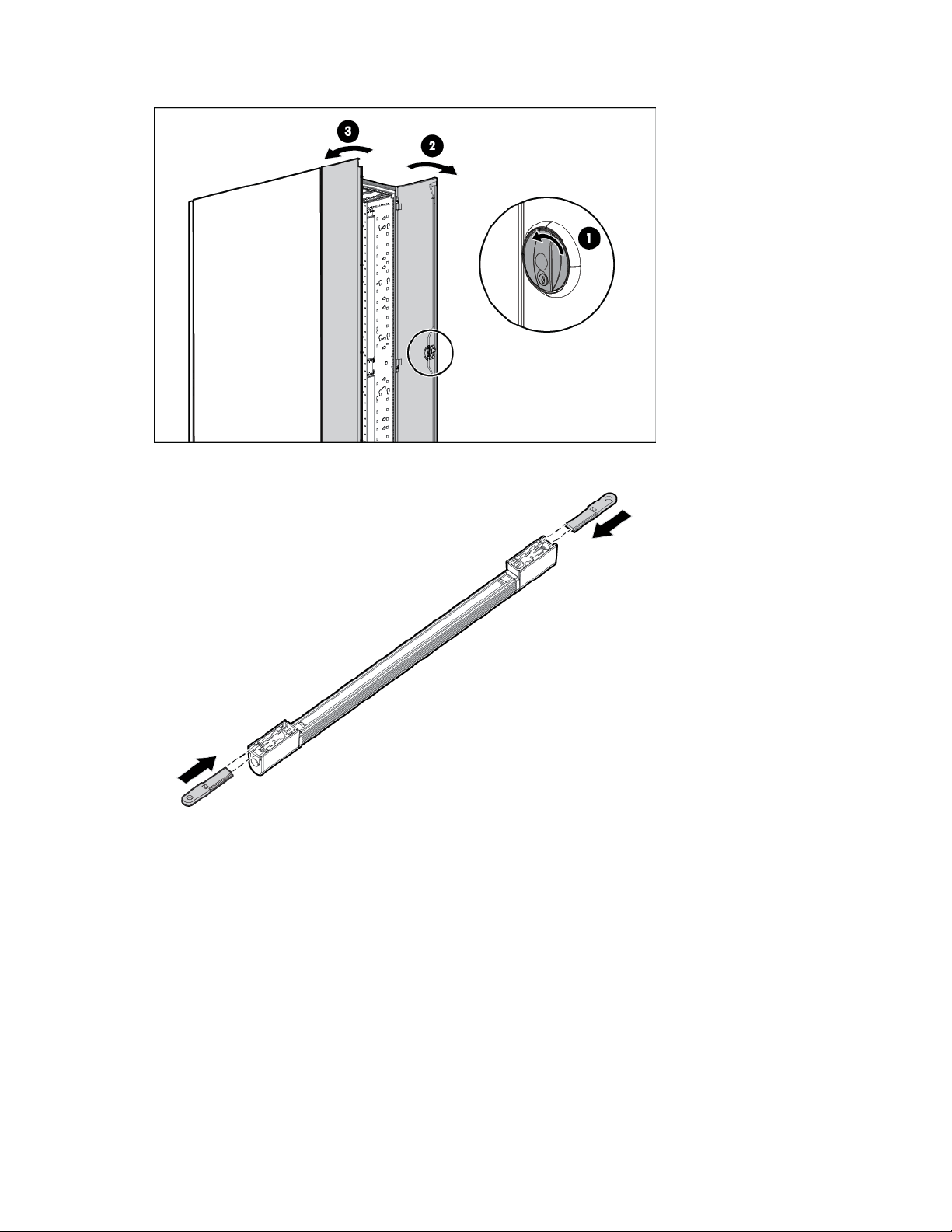
Open the back door of the rack to install the HP LED Light kit.
1.
2. Slide one mounting plate onto the back of each side of the LED light.
LED Light kit 72
Page 73
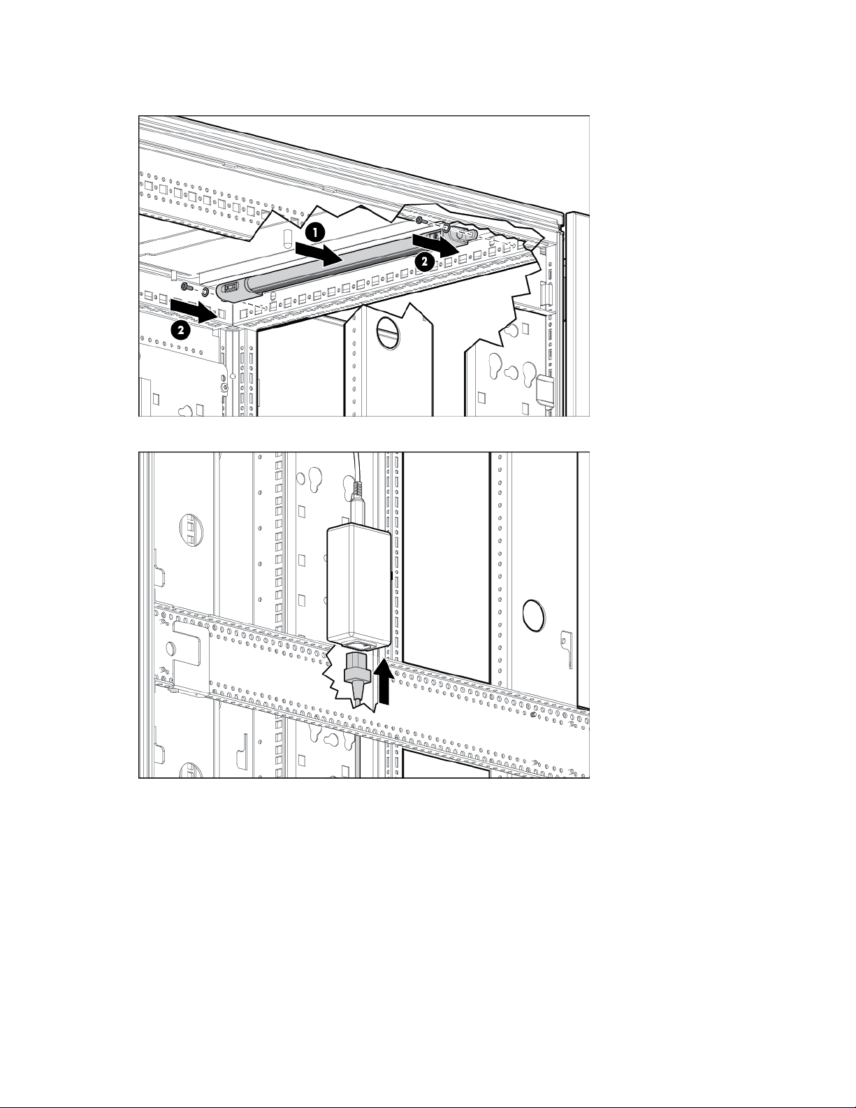
Place one screw and one washer through the front hole of the mounting plate. Repeat for each side of
3.
the LED light, and then connect the LED light to the top-back of the rack.
4. Connect the power cord to the power adapter.
LED Light kit 73
Page 74
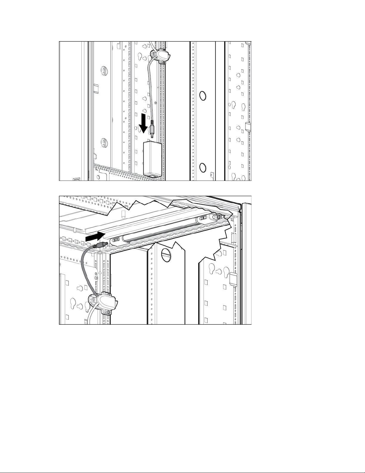
Connect the short end of the LED light switch connector to the power adapter.
5.
6. Connect the long end of the LED light switch connector to the LED light.
LED Light kit 74
Page 75
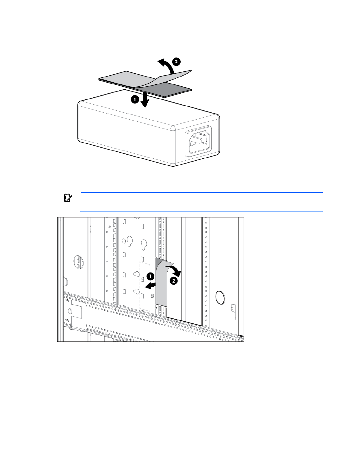
Remove the plastic backing from the hook-and-loop piece, and then attach the adhesive side of the
7.
hook-and-loop piece to the power adapter.
8. Remove the plastic backing from the second hook-and-loop piece, and then attach it to the cable
management bracket inside the rack.
IMPORTANT: The power adapter can be mounted anywhere that there is available free space
along the cable management bracket.
LED Light kit 75
Page 76
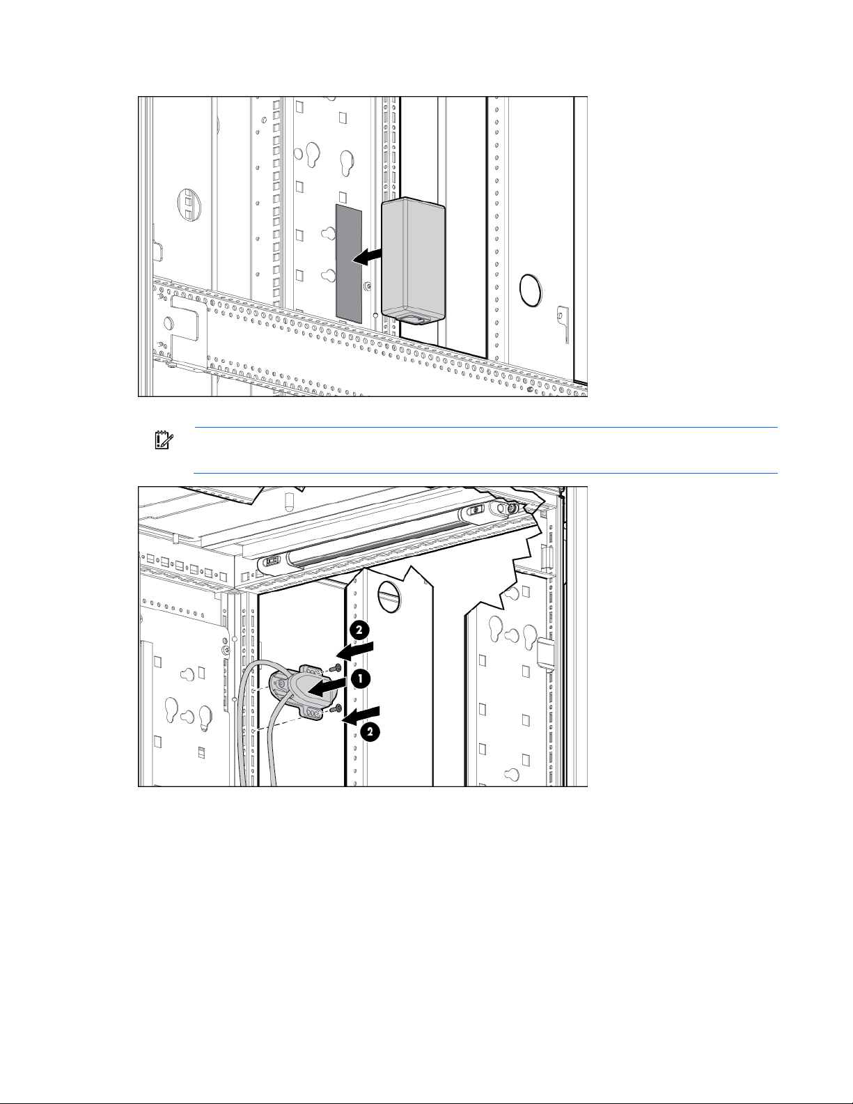
Attach the two hook-and-loop pieces together.
9.
10. Attach the switch to the rack using the screws provided.
IMPORTANT: The light switch can be mounted anywhere that there is available free space along
the vertical frame member.
11. Using the appropriate power cord, be sure that the kit is plugged into the PDU.
12. Be sure that the LED light is in the "on" position. When the rack door is opened and closed, the light
automatically powers on and power off via the switch that is provided with the LED light.
Installation is complete.
LED Light kit 76
Page 77
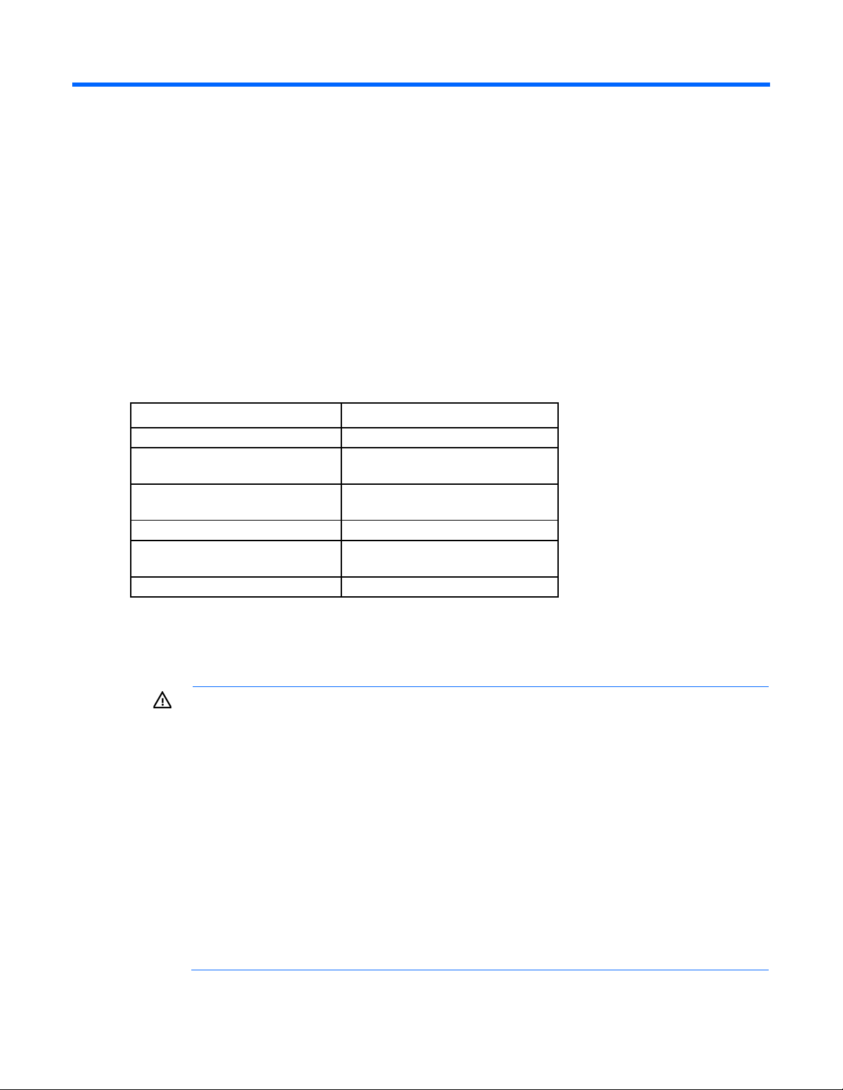
Location Discovery kit
HP 14U Location Discovery Kit
Two modules (two 7U modules)
Three modules (two 7U modules and
Five modules (four 7U modules and one
HP 42U Location Discovery Kit
Six modules (six 7U modules)
Six modules (one 7U module and five
HP 48U Location Discovery Kit
Six modules (six 8U modules)
HP
About this device
HP provides built-in location awareness in the new ProLiant servers, a capability that works hand-in-hand with
technology in the HP Advanced Series Racks and Enterprise Series Racks. Together these technologies
provide the rack identification number and precise U location of the servers. This information is
communicated through SIM, ICPM, and HP iPDUs.
For LDS software requirements, see the QuickSpecs on the HP website
(http://www.hp.com/go/rackandpower).
Kit contents
Kit Modules
HP 22U Location Discovery Kit
HP 36U Location Discovery Kit
HP 47U Location Discovery Kit
Each kit option includes a Location Discovery Services serial number label for placement on the rack.
Precautions
one 8U module)
8U module)
8U modules)
WARNING: A risk of personal injury or damage to the equipment exists. Before installing the
LDS modules in a populated rack, be sure that the rack is stabilized in accordance with all product
and rack warnings. When installing the modules, you must partially extend one or more rack
mounted devices (up to 8U of devices) at a time. Only single devices that are mounted on slide
rails are intended to be fully extended from the rack and remain in a safe and upright position.
To reduce the risk of personal injury, damage to the equipment, or rack instability:
• Do not extend more devices than necessary to install a single 7U or 8U module. To prevent the
rack from becoming unstable, do not extend any device more than 9 cm (3.5 in) from the rack.
• If a device is mounted on non-slide, static rails and it must be extended more than 9 cm (3.5
in), remove the device completely from the rack. For more information about removing the
device from the rack, see the device installation instructions.
• If a device is secured to the rack and not mounted on rails, remove the device completely from
the rack.
For more information about extending devices from the rack, see Racking Best Practices on the
website (http://www.hp.com/go/infrastructure).
Location Discovery kit 77
Page 78
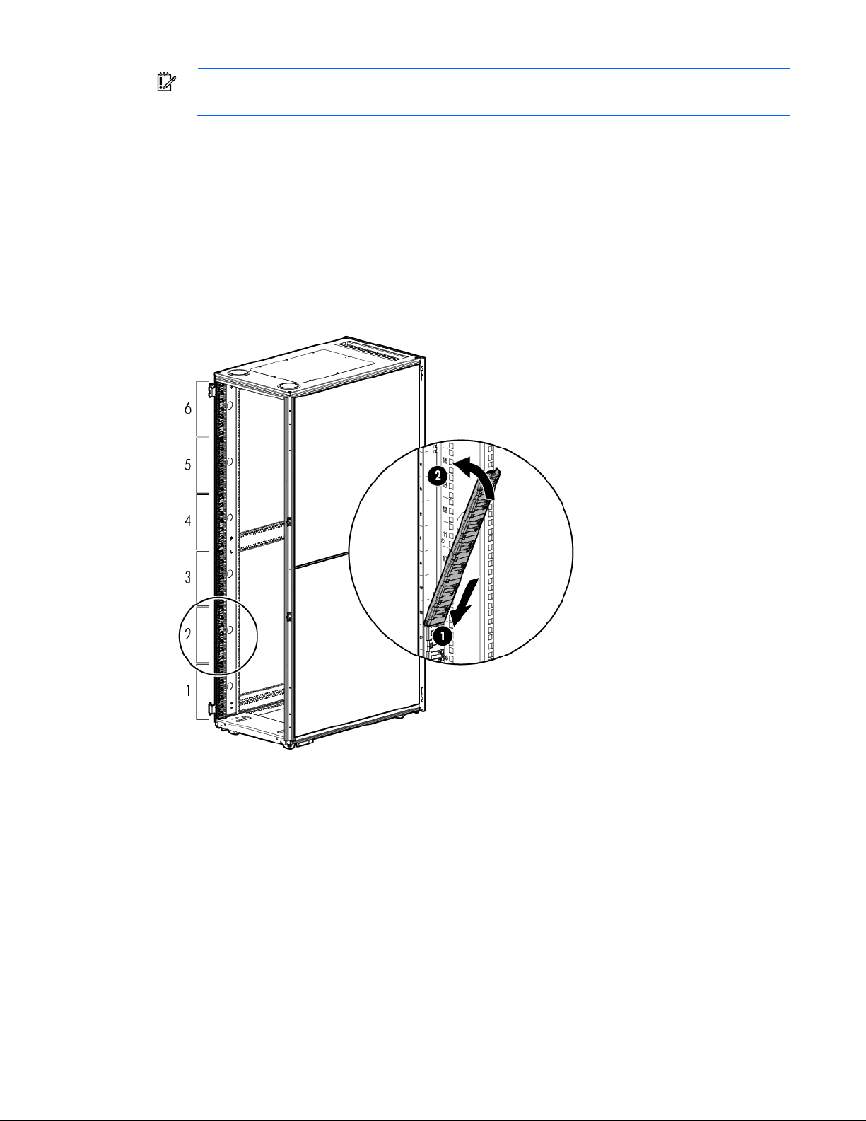
IMPORTANT: The modules mu
st be installed in the correct numerical order. The order number is
listed on the installation label, and the U location is listed on the pull tab.
Installing the modules
1. If there is a front-mounted device installed in the rack, extend the device to allow for module installation.
If there is a blanking panel installed in the rack, remove the panel.
For instructions on extending the device, see the specific device user guide.
For safety precautions, see "Precautions (on page 77)."
2. Install the modules in the correct numerical order beginning at the bottom of the rack. The installation
label on each module lists the numerical position within the rack.
3. After all the modules are installed, you can remove the installation labels from the modules.
Location Discovery kit 78
Page 79
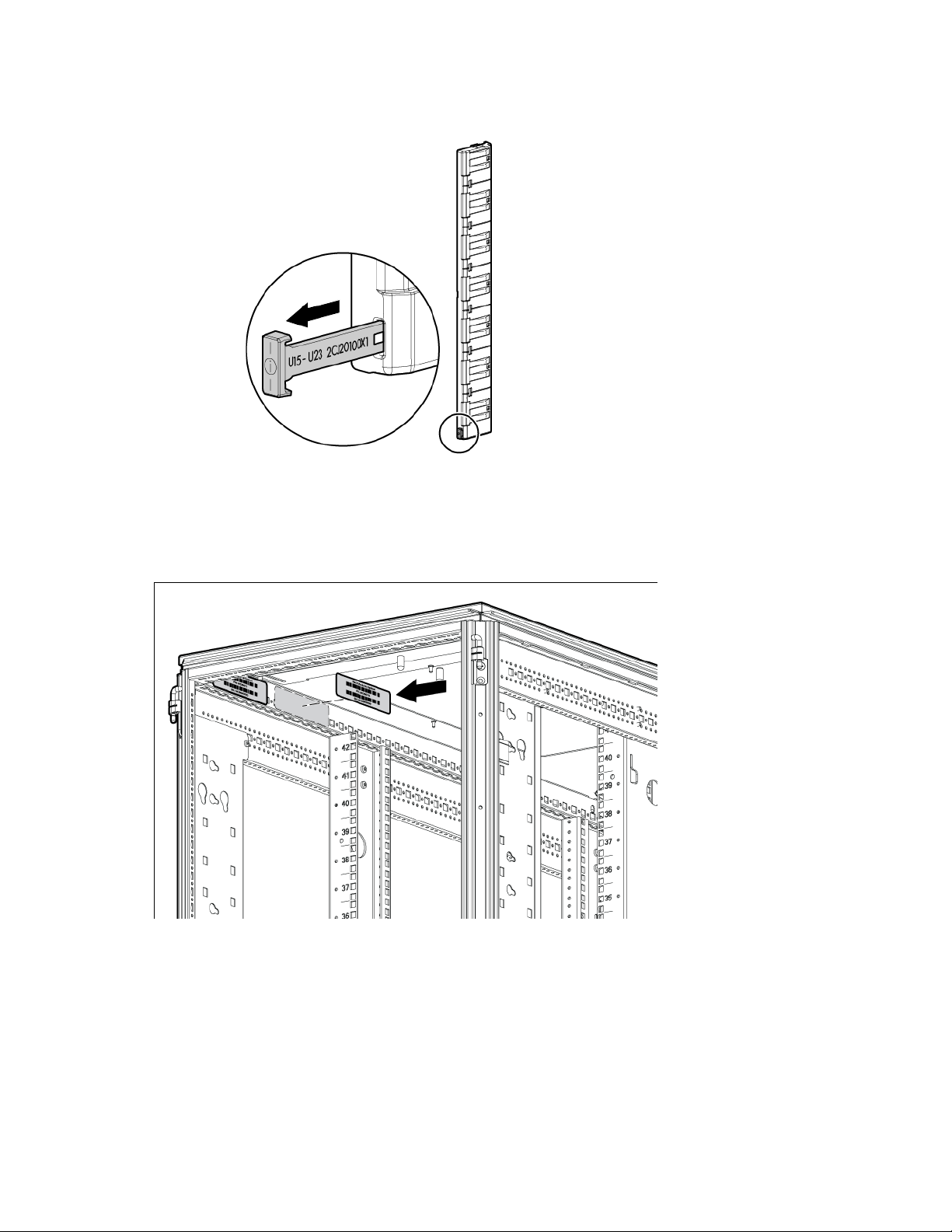
Each module has a pull tab that contains the module serial number/rack identifier number and the
installation U location.
4. Slide the front-mounted device into the rack, and then secure the device to the rack.
5. Reset iLO.
6. Adhere the Discovery Services serial number label to the rack next to the rack's serial number label.
The Discovery Services label is packed in the kit.
7. Power on the server, and then the Discovery Services data is available.
The installation is complete.
Location Discovery kit 79
Page 80
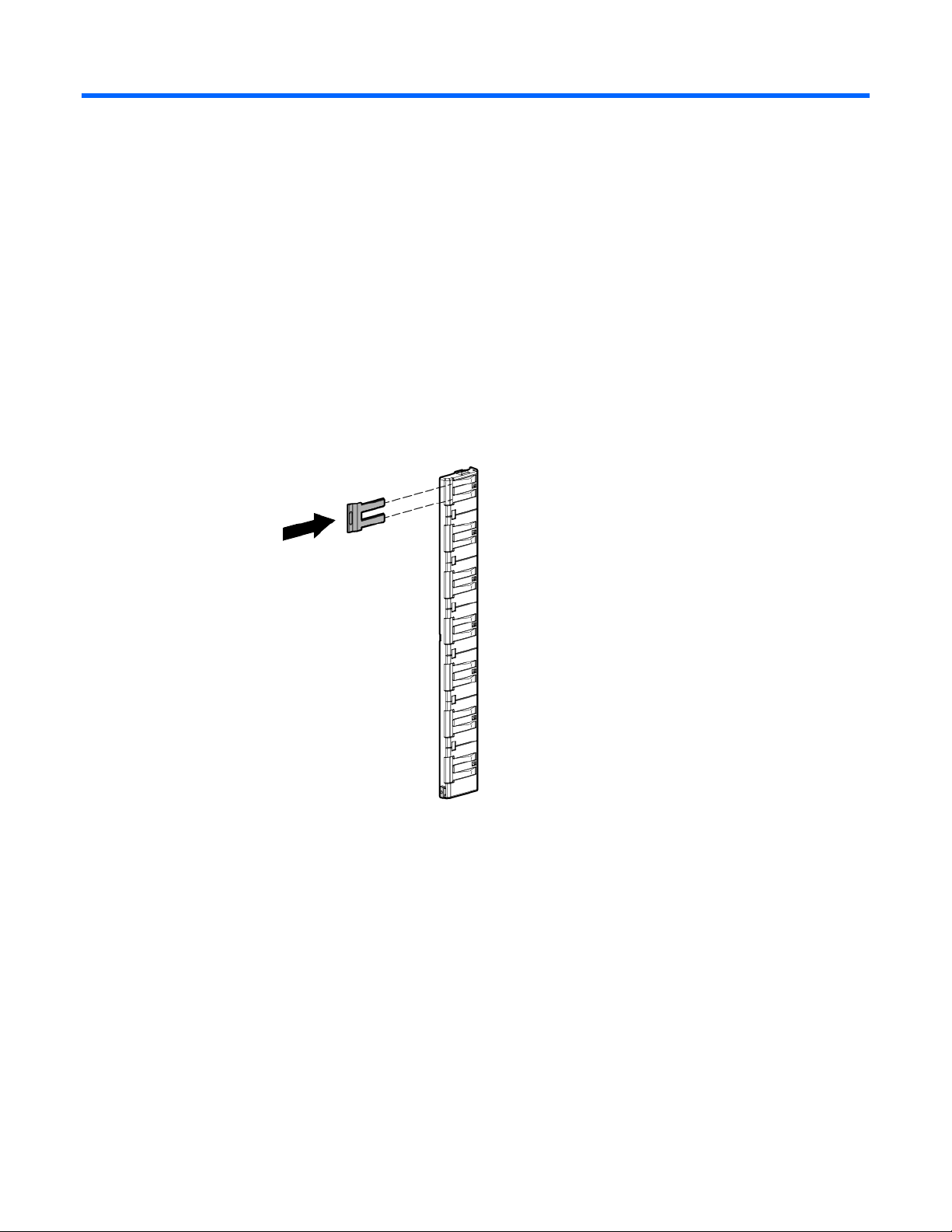
Location Discovery Contact Cover kit
About this device
This kit includes covers for location discovery contacts in the HP Advanced Series Racks and Enterprise Series
Kit contents
Racks.
Contact covers
Installing the contact covers
Location Discovery Contact Cover kit 80
Page 81
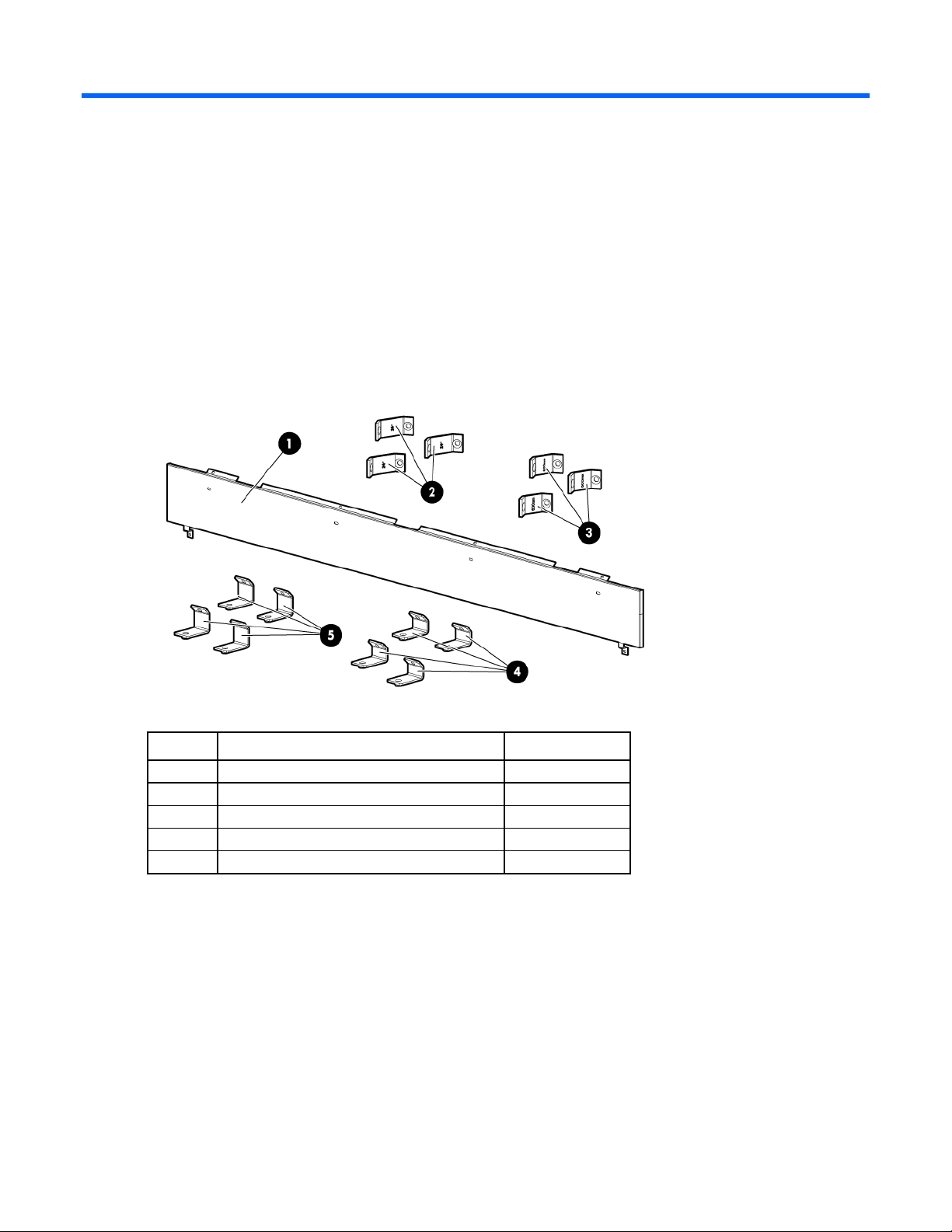
Offset Baying kit
1
Panel
1 2 600 mm front baying brackets
3
3
24 in front baying brackets
3
4
600 mm rear adapter brackets
4
5
24 in rear adapter brackets
4
About this device
The Offset Baying kit enables you to connect multiple HP Advanced Series Racks and Enterprise Series Racks
of different depths. Kit contents include hardware for connecting racks and a panel to cover the gap at the
BW941A kit contents
rear of the two racks.
Item Description Quantity
Offset Baying kit 81
Page 82
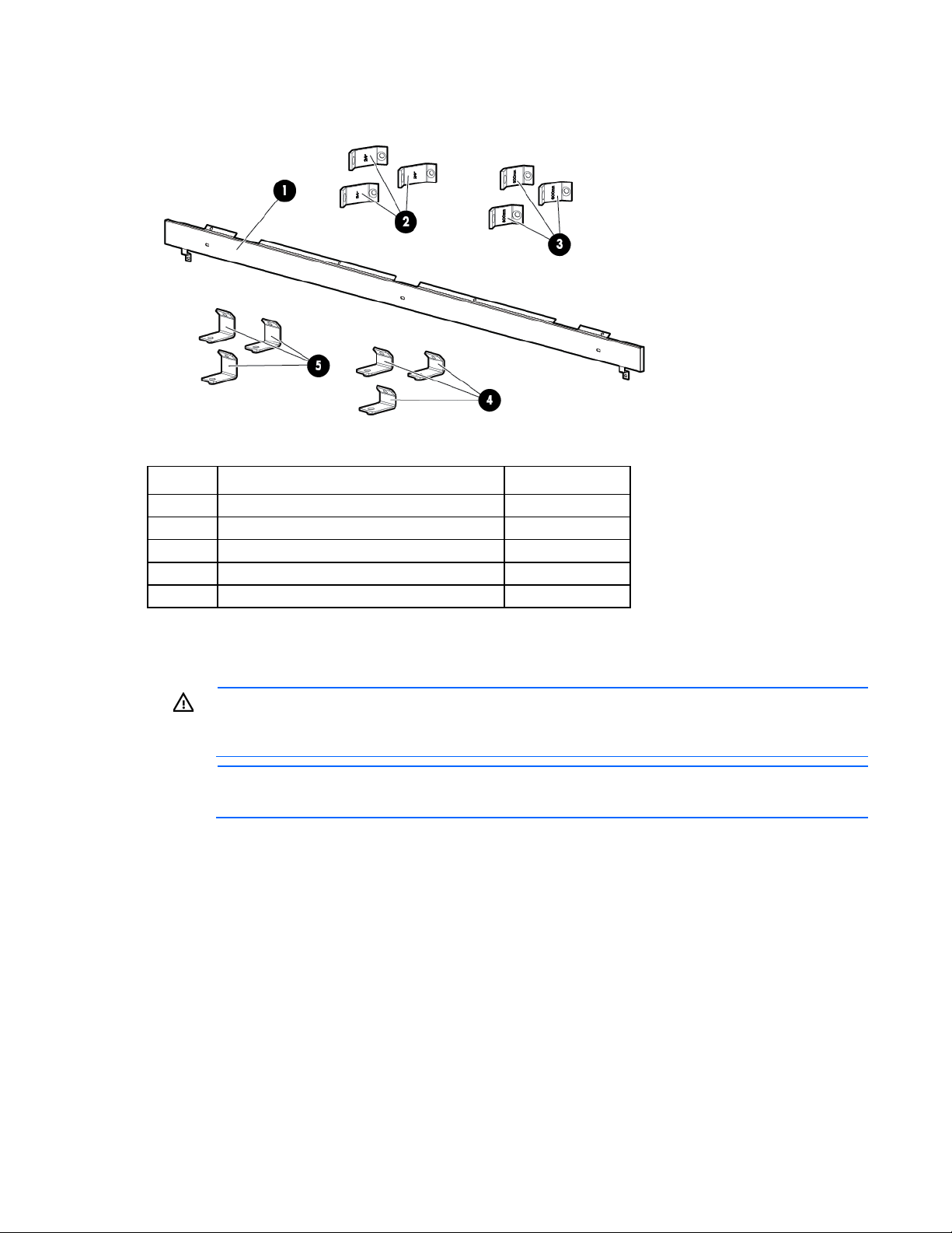
BW952A kit contents
1
Panel
1 2 600 mm front baying brackets
3
3
24 in front baying brackets
3
4
600 mm rear adapter brackets
3
5
24 in rear adapter brackets
3
Item Description Quantity
Installing the baying kit
WARNING: To reduce the risk of personal injury or damage to the rack and equipment, the
racks must be positioned and secured together according to these instructions. Failure to do so
could result in an unstable installation.
NOTE: The appearance of the rack might vary depending on the model of the rack purchased.
Offset Baying kit 82
Page 83
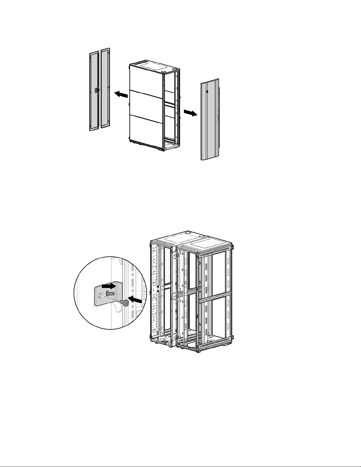
Remove the front and rear doors.
1.
2. Remove the side panels (if present between the racks).
3. Position the racks side by side, ensuring that the feet of the racks are on solid flooring (no cracks or
openings).
4. Place the panel onto the rack, and then place the rear brackets onto the panel.
5. Using two T-30 Torx screws in each bracket, attach three baying brackets (either 24-inch or 600-mm,
depending on the floor layout) to the front and rear of each rack set.
Offset Baying kit 83
Page 84
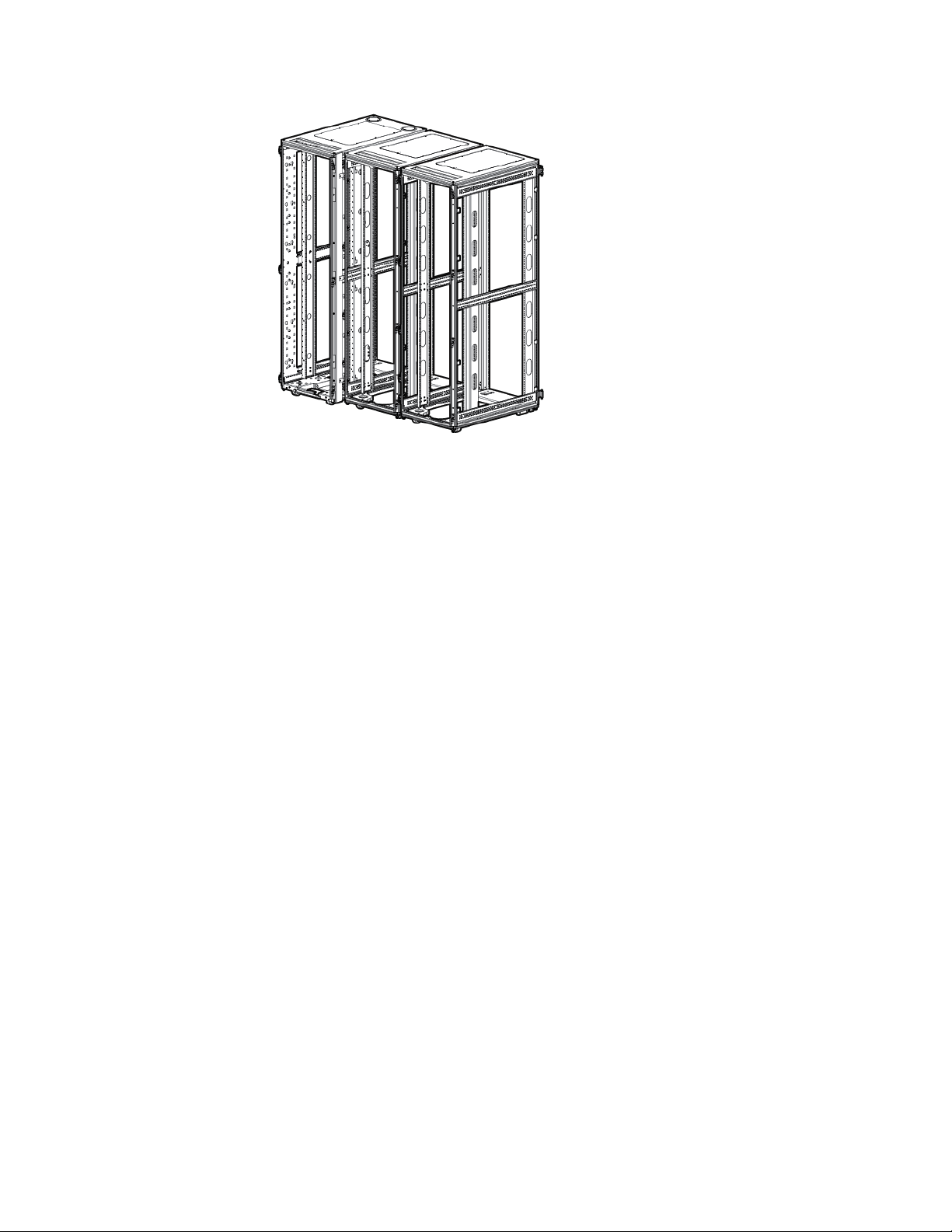
Bay any additional racks.
6.
7. Attach side panels to each end of the bayed racks, and then re-attach the front and rear doors.
Installation is complete.
Offset Baying kit 84
Page 85
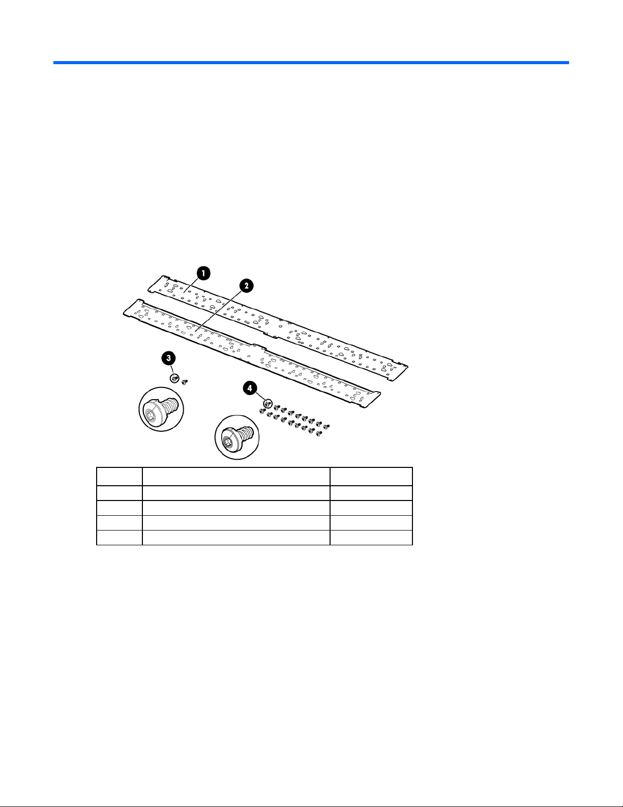
PDU Bracket Kit
1
PDU management bracket (right)
1 2 PDU management bracket (left)
1
3
Screw, serrated head grounding
2
4
Screw, M5, 5X10 self tapping
18
About this device
The PDU bracket kit enables you to attach additional PDU brackets to HP Advanced Rack Series and
Kit contents
Enterprise Series Racks.
If any of the following items are missing or damaged, contact an HP authorized reseller.
Item Description Quantity
Required tools
The following tools are required for installation:
T-25 Torx driver
PDU Bracket Kit 85
Page 86
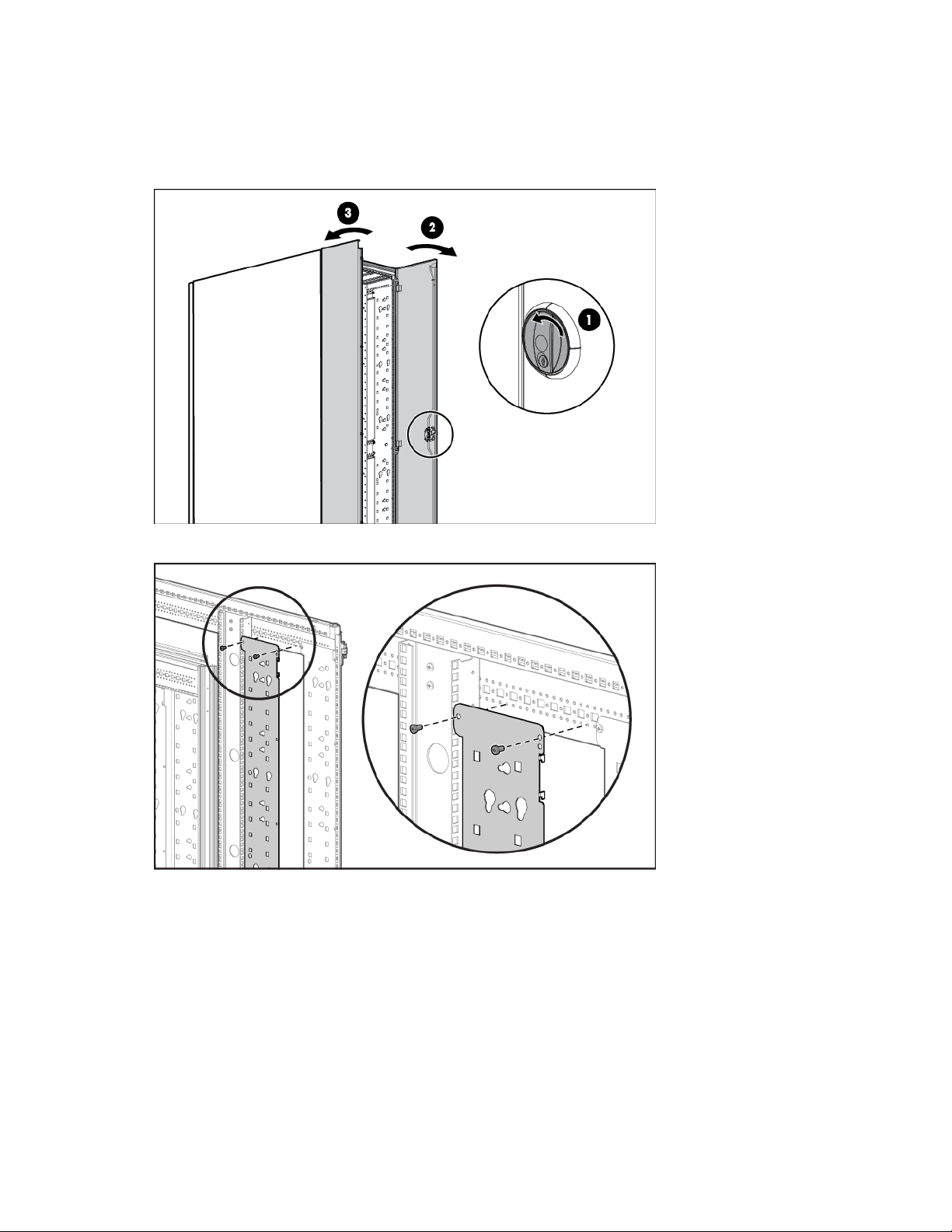
Installing the PDU bracket
To install the right bracket:
1. Open the back door of the rack.
2. Attach the top of the bracket with two M5 self-tapping screws.
PDU Bracket Kit 86
Page 87
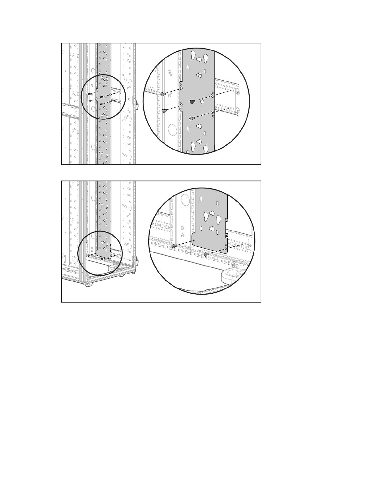
Attach the middle section using three M5 self-tapping screws and one serrated-head grounding screw.
3.
4. Attach the bottom with two M5 self-tapping screws.
Follow the same procedure to install the left bracket.
PDU Bracket Kit 87
Page 88
Server/Utility Shelf kit
Server/Utility shelf
1
Cage nut
2
M6 screw
2
Quick-release tie-down straps
2
About this device
The HP Server/Utility Shelf kit enables you to install a convenient shelf in your rack-mount system. This kit can
be used with all HP racks.
Kit contents
Item Quantity
This kit might contain extra hardware for your convenience.
Required tools
The following tools are required for installation:
• Phillips screwdriver
• Cage nut insertion tool
Installing the server/utility shelf
Always plan the rack installation so that the heaviest item is on the bottom of the rack. Install the heaviest item
first, and then continue to populate the rack from the bottom to the top.
Server/Utility Shelf kit 88
Page 89
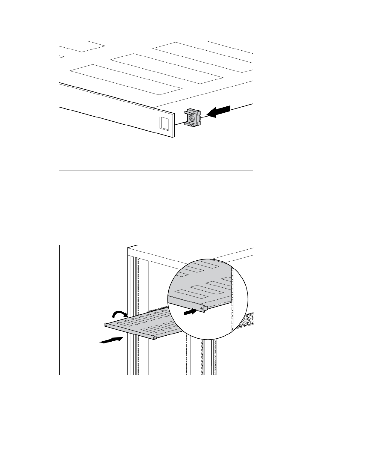
Align the cage nuts with the square-rail perforations on the front of the shelf.
1.
2. Use the cage nut insertion tool (not included) to secure each cage nut to the shelf.
a. Hook the bottom lip of the cage nut in the square-rail perforation.
b. Insert the tip of the insertion tool through the perforation, and then hook the top lip of the cage nut.
c. Pull the cage nut through the square-rail perforation until the top lip snaps into position.
3. Firmly hold the shelf, and then insert the shelf into the rack, tilting the shelf slightly so that the rear teeth
on the shelf clear the rear of the rack.
4. Straighten the shelf, and then insert the rear teeth into the mounting holes on the rear of the rack.
Server/Utility Shelf kit 89
Page 90
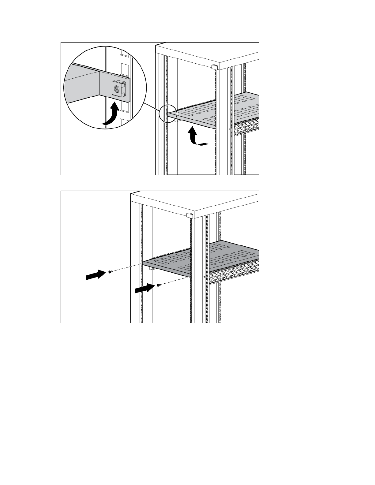
Align each cage nut assembly with the mounting holes on the inside front of the rack.
5.
6. Secure the shelf to the rack with two M6 screws using a Phillips screwdriver.
Server/Utility Shelf kit 90
Page 91
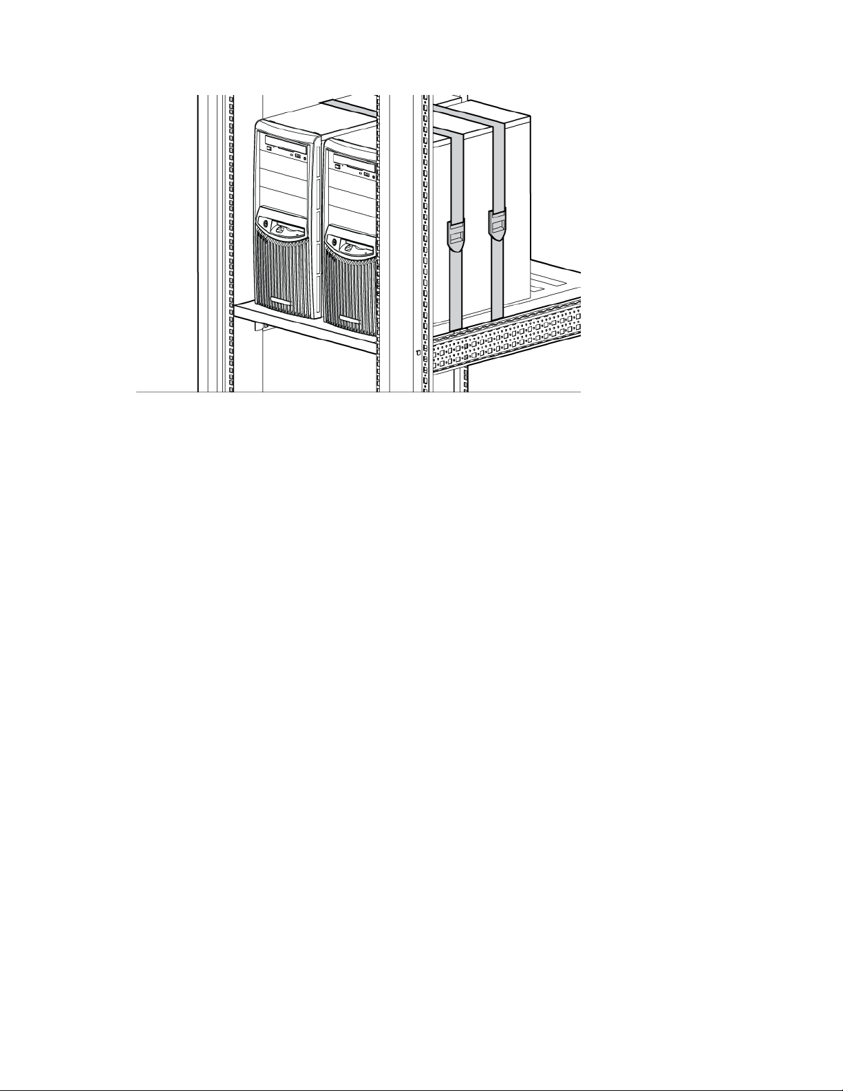
Secure servers to the shelf using the quick-release tie-down straps.
7.
Installation is complete.
Server/Utility Shelf kit 91
Page 92
Side Panel kit
Top side panel
2
Middle side panel
2
Bottom side panel
2
Key
4
About this device
The Side Panel kit enables you to attach side panels to the HP Advanced Rack Series and Enterprise Series
Racks.
Kit contents
Item Quantity
This kit might contain extra hardware for your convenience.
Required tools
No tools are required for this procedure.
Side Panel kit 92
Page 93
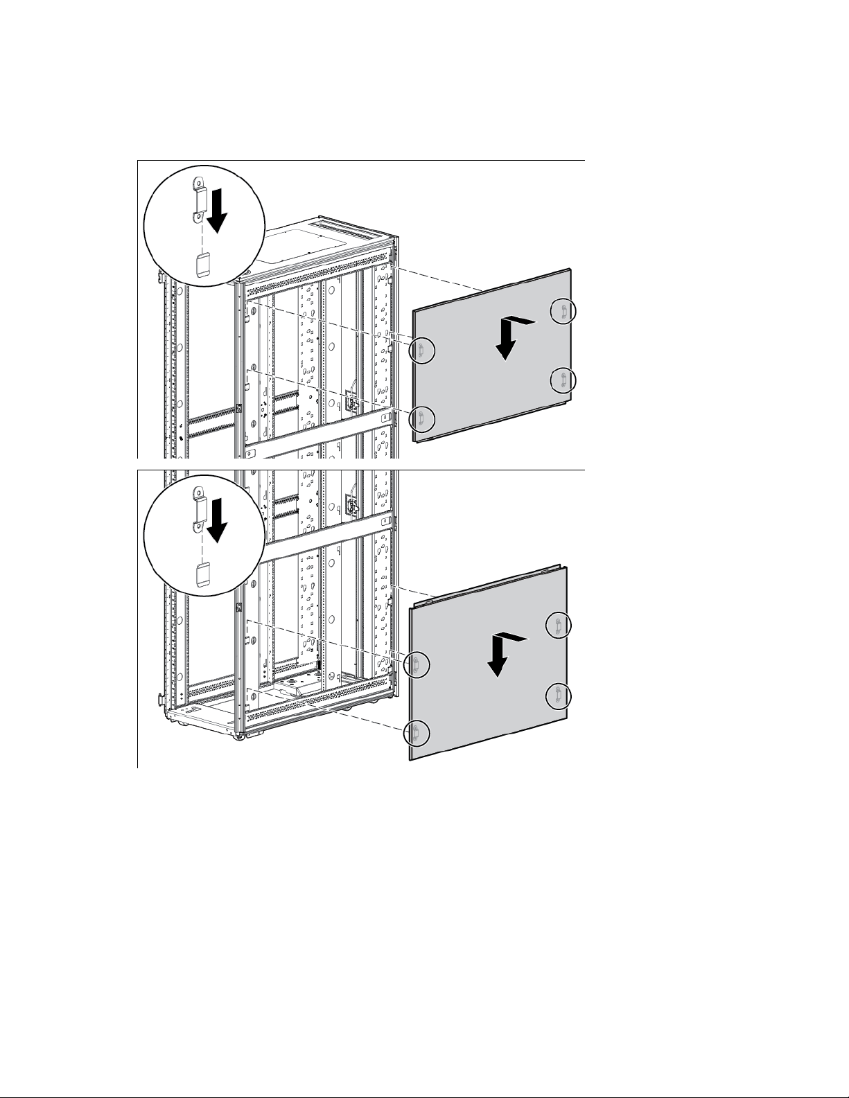
Installing the side panels
1. There are three side panel kits incorporated in this process. Install the top and bottom side panel by
sliding the brackets on the side panel behind the tabs on the rack frame.
Side Panel kit 93
Page 94
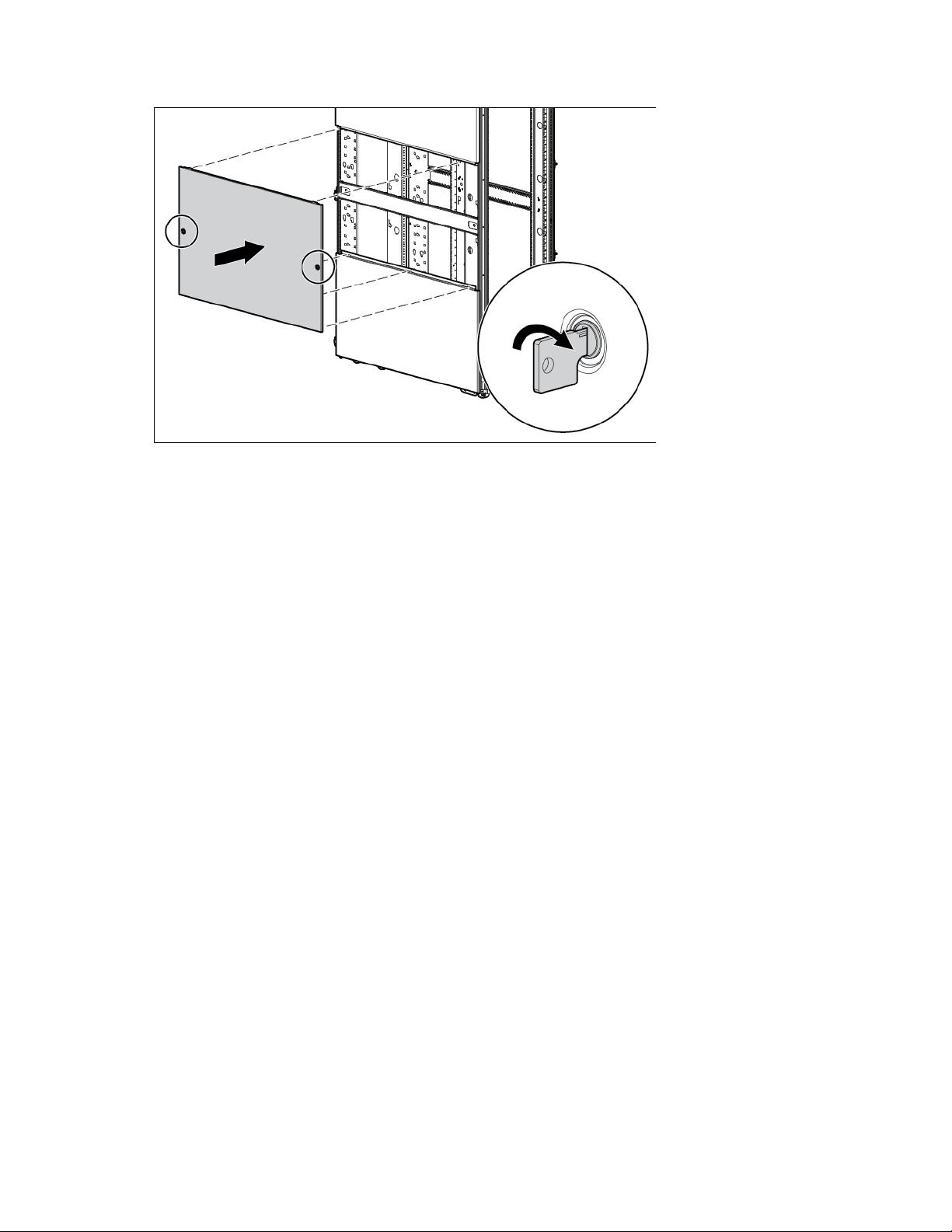
Install the middle side panel by locking the side panel locks, securing it to the rack.
2.
3. Repeat steps 1 and 2 for the other side of the rack.
Installation is complete.
Side Panel kit 94
Page 95
Stabilizer kit
600-mm (23.62-inch) Front stabilizer mount
1
Stabilizer feet
2
M8 x 30-mm bolt
8
M8 flat washer
8
from the side. If you are stabilizing racks that are secured together with baying kits, the side feet
About this device
The Stabilizer kit provides stability and support and prevents possible tipping when you install, remove, or
access equipment within the HP Advanced Series Racks and Enterprise Series Racks.
The stabilizer kit is either required or recommended, depending on your rack configuration. There are four
stabilizer kit options.
• The standard 600-mm (23.6 in) or 800-mm (31.5 in) front foot is required with deployments of
stand-alone racks. Rack rows with four or more bayed racks, without a single rack-mountable
component exceeding 99.8 kg (220 lb), do not need a stabilizer kit installed.
• The heavy duty 600-mm (23.6 in) front foot is required when a single rack-mountable component
weighing 99.8 kg (220 lb) or more is installed in a stand-alone rack or in a rack belonging to a rack
row of three or fewer bayed racks.
Kit contents
Item Quantity
This kit might contain extra hardware for your convenience.
Required tools
The following tools are required for installation:
• Ratchet with sockets
• Adjustable wrench
Installing the stabilizer
NOTE: HP recommends using the side feet, provided with this kit, to stabilize stand-alone racks
1. Raise the rack with leveling feet to align the front foot with the front caster plate.
are optional on either end of the row.
Stabilizer kit 95
Page 96
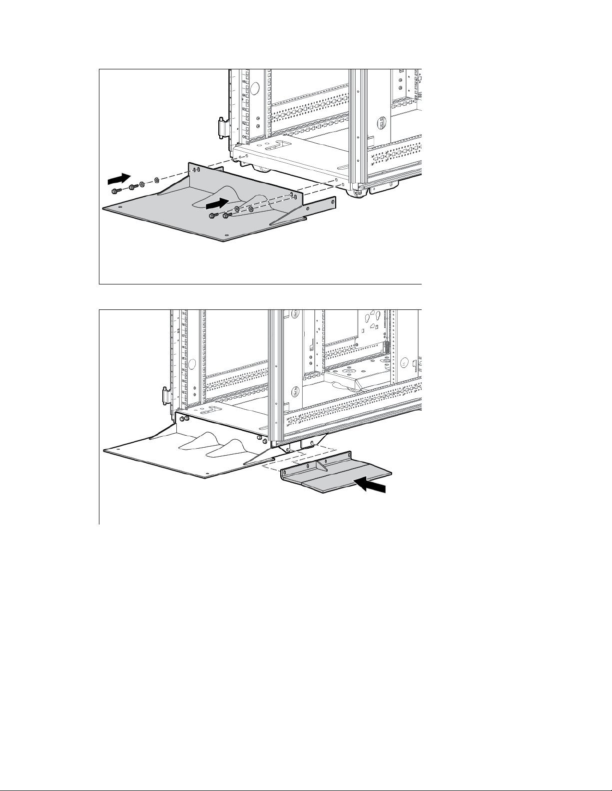
Insert and partially tighten four bolts with washers, securing the front foot to the front caster plate.
2.
3. If you are using the side feet, align the side feet with the holes on the caster plate skirt and front foot.
Stabilizer kit 96
Page 97
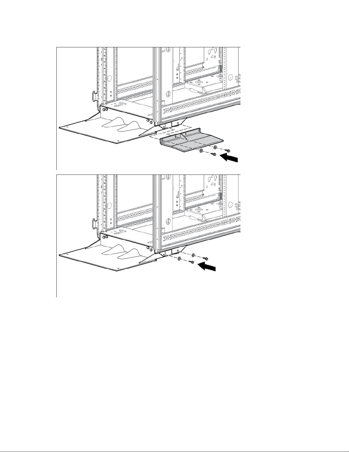
Insert and partially tighten two bolts with washers, securing the side feet (if installed) and front foot to the
4.
caster plate skirt.
5. Tighten the bolts from step 2.
6. Tighten the bolts from step 4.
Installation is complete.
Stabilizer kit 97
Page 98
Tie-Down kit
Front tie-down bracket
1
Rear tie-down bracket
1
M8 x 20-mm bolt
8
M8 flat washer
8
M8 spring clip
4
About this device
There are two separate tie-down kits used to secure the HP Advanced Series Racks and Enterprise Series
Racks:
• Advanced Series Rack Tie-down kit supports all HP Advanced Series Racks.
• Enterprise Series Rack Tie-down kit supports all HP Enterprise Series Racks.
Required tools
The following tools are required for installation:
• Ratchet with sockets
• Adjustable wrench
Advanced Series Rack Tie-down kit
Advanced Series Rack Tie-down kit contents
The Advanced Series rack tie-down kit contents includes the following items.
Item Quantity
Installing the Advanced Series Rack Tie-down kit
This kit might contain extra hardware for your convenience.
This procedure is for all HP Advanced Series Racks.
To install the tie-down kit:
1. Adjust the leveling feet on the rack so that the full weight of the rack rests on the leveling feet.
2. Align the front tie-down with the holes on the front caster plate.
Tie-Down kit 98
Page 99
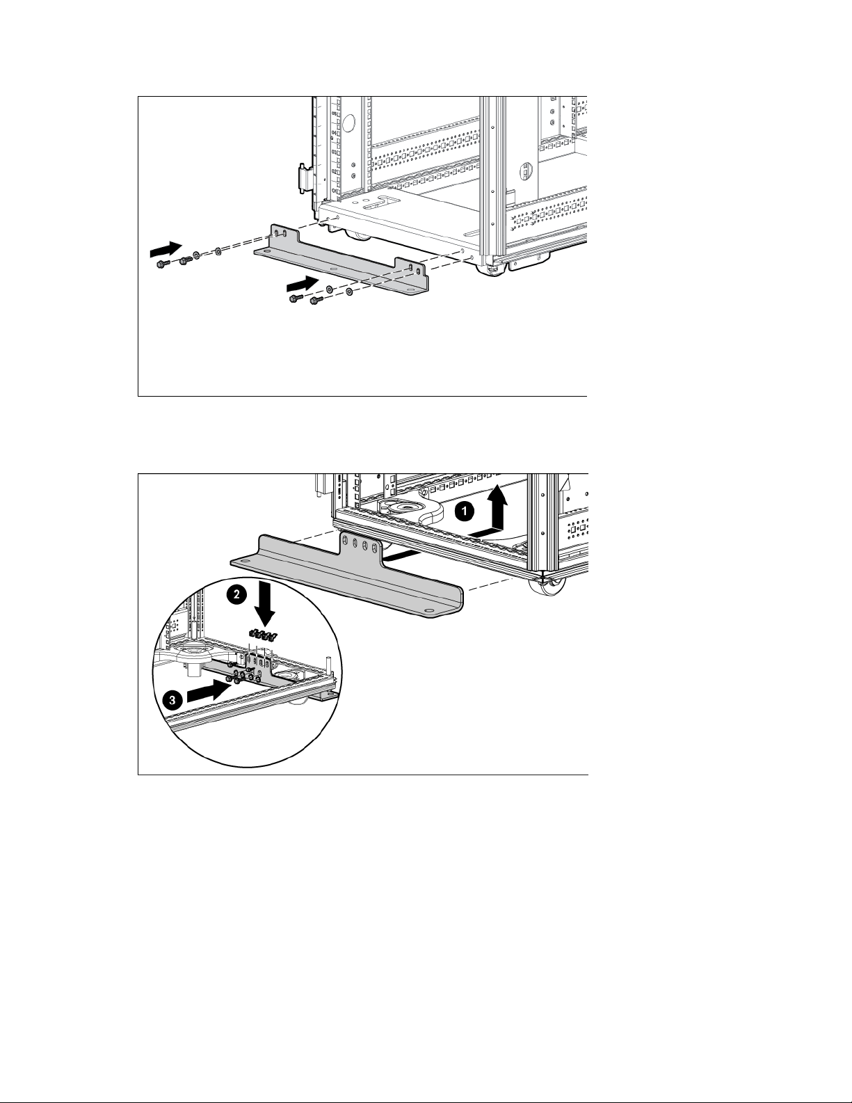
Insert and partially tighten four bolts with washers, securing the front tie-down to the front caster plate.
3.
4. Align the rear tie-down with the holes on the rear caster plate.
5. Insert the four spring clips, and then partially tighten four bolts with washers, securing the rear tie-down
to the rear caster plate.
6. Tighten the bolts from step 3.
7. Tighten the bolts from step 5.
8. Secure the rack to the floor ("Securing the rack to the floor" on page 100).
The installation is complete.
Tie-Down kit 99
Page 100
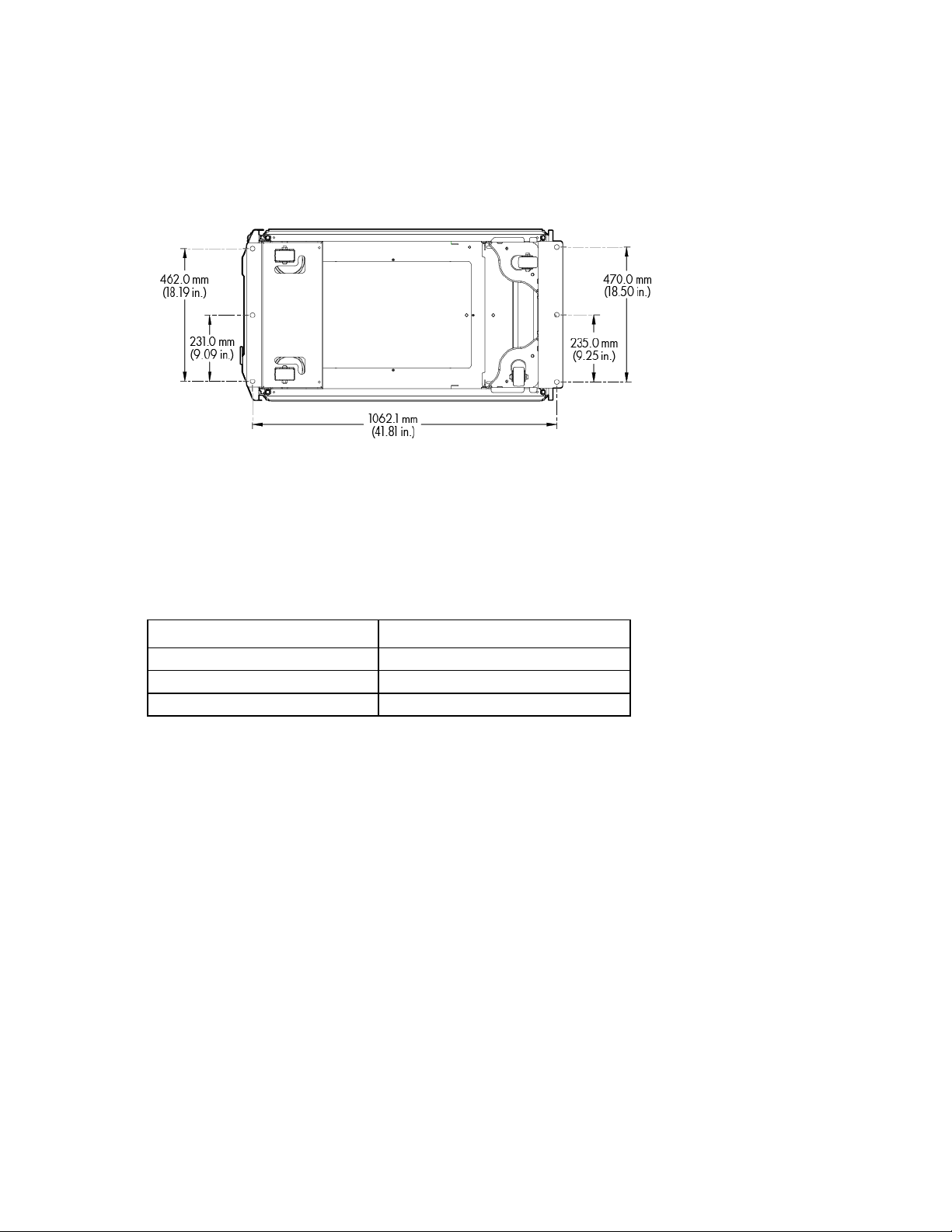
Securing the rack to the floor
Tie-down bracket
2
M8 x 20-mm bolt
10
M8 flat washer
10
The following illustration indicates where to drill the holes to secure the rack to the floor. The distances are
measured from the holes on the tie-downs. Have your building structural engineer drill the holes. After your
holes have been drilled, insert a bolt with a washer into each hole to secure the rack to the floor.
Enterprise Series Rack Tie-down kit
Enterprise Series Rack Tie-down kit contents
The Enterprise Series Rack Tie-down Kit includes the following items.
Item Quantity
Installing the Enterprise Series Rack Tie-down kit
These kits might contain extra hardware for your convenience.
1. Adjust the leveling feet on the rack so that the full weight of the rack rests on the leveling feet.
2. Align the front tie-down with the holes on the front caster plate.
Tie-Down kit 100
 Loading...