

Page 1

HP ProCurve Switch Software
IPv6 Configuration Guide
3500 switches
3500yl switches
5400zl switches
6200yl switches
6600 switches
8200zl switches
Software version K.14.52
March 2010
Page 2

Page 3

HP ProCurve
3500 Switches
3500yl Switches
5400zl Switches
6200yl Switch
6600 Switches
8200zl Switches
IPv6 Configuration Guide
March 2010
K.14.52
Page 4

© Copyright 2008 - 2010 Hewlett-Packard Development Company,
L.P. The information contained herein is subject to change without notice. All Rights Reserved.
This document contains proprietary information, which is
protected by copyright. No part of this document may be
photocopied, reproduced, or translated into another
language without the prior written consent of HewlettPackard.
Publication Number
5992-3067
March 2010
Applicable Products
HP ProCurve Switch 3500-24 (J9470A)
HP ProCurve Switch 3500-48 (J9472A)
HP ProCurve Switch 3500-24 PoE (J9471A)
HP ProCurve Switch 3500-48 PoE (J9473A)
HP ProCurve Switch 3500yl-24G-PWR (J8692A)
HP ProCurve Switch 3500yl-48G-PWR (J8693A)
HP ProCurve Switch 3500yl-24G-PoE+ (J9310A)
HP ProCurve Switch 3500yl-48G-PoE+ (J9311A)
HP ProCurve Switch 5406zl (J8697A)
HP ProCurve Switch 5412zl (J8698A)
HP ProCurve Switch 6200yl-24G (J8992A)
HP ProCurve Switch 8206zl (J9475A)
HP ProCurve Switch 8212zl (J8715A/B)
HP ProCurve Switch 6600-24G (J9263A)
HP ProCurve Switch 6600-24G-4XG (J9264A)
HP ProCurve Switch 6600-24G-24XG (J9265A)
HP ProCurve Switch 6600-48G (J9451A)
HP ProCurve Switch 6600-48G-4XG (J9452A)
HP ProCurve 24-Port 10/100/1000 PoE+ zl Module (J9307A)
HP ProCurve 20-Port 10/100/1000 PoE+/4-Port
MiniGBIC zl Module (J9308A)
HP ProCurve 4-Port 10GbE SFP+ zl Module (J9309A)
HP ProCurve 24-Port 10/100 PoE+ zl Module (J9478A)
Disclaimer
The information contained in this document is subject to
change without notice.
HEWLETT-PACKARD COMPANY MAKES NO WARRANTY
OF ANY KIND WITH REGARD TO THIS MATERIAL,
INCLUDING, BUT NOT LIMITED TO, THE IMPLIED
WARRANTIES OF MERCHANTABILITY AND FITNESS
FOR A PARTICULAR PURPOSE. Hewlett-Packard shall not
be liable for errors contained herein or for incidental or
consequential damages in connection with the furnishing,
performance, or use of this material.
The only warranties for HP products and services are set
forth in the express warranty statements accompanying
such products and services. Nothing herein should be
construed as constituting an additional warranty. HP shall
not be liable for technical or editorial errors or omissions
contained herein.
Hewlett-Packard assumes no responsibility for the use or
reliability of its software on equipment that is not furnished
by Hewlett-Packard.
Warranty
See the Customer Support/Warranty booklet included with
the product.
A copy of the specific warranty terms applicable to your
Hewlett-Packard products and replacement parts can be
obtained from your HP Sales and Service Office or
authorized dealer.
Trademark Credits
Microsoft, Windows, and Microsoft Windows NT are US
registered trademarks of Microsoft Corporation. Java™ is a
US trademark of Sun Microsystems, Inc.
Hewlett-Packard Company
8000 Foothills Boulevard, m/s 5551
Roseville, California 95747-5551
http://www.procurve.com
Page 5

Contents
Product Publications and IPv6 Command Index
About Your Switch Manual Set . . . . . . . . . . . . . . . . . . . . . . . . . . . . xiii
Printed Publications. . . . . . . . . . . . . . . . . . . . . . . . . . . . . . . . . . . . . . . . . . xiii
Electronic Publications . . . . . . . . . . . . . . . . . . . . . . . . . . . . . . . . . . . . . . . xiii
IPv6 Command Index . . . . . . . . . . . . . . . . . . . . . . . . . . . . . . . . . . . . . xv
1 Getting Started
Contents . . . . . . . . . . . . . . . . . . . . . . . . . . . . . . . . . . . . . . . . . . . . . . . . . . . . . . 1-1
Introduction . . . . . . . . . . . . . . . . . . . . . . . . . . . . . . . . . . . . . . . . . . . . . . . . . . 1-2
Conventions . . . . . . . . . . . . . . . . . . . . . . . . . . . . . . . . . . . . . . . . . . . . . . . . . . 1-2
Command Syntax Statements . . . . . . . . . . . . . . . . . . . . . . . . . . . . . . . . . 1-2
Command Prompts . . . . . . . . . . . . . . . . . . . . . . . . . . . . . . . . . . . . . . . . . . 1-3
Screen Simulations . . . . . . . . . . . . . . . . . . . . . . . . . . . . . . . . . . . . . . . . . . 1-3
Configuration and Operation Examples . . . . . . . . . . . . . . . . . . . . . . . . . 1-3
Keys . . . . . . . . . . . . . . . . . . . . . . . . . . . . . . . . . . . . . . . . . . . . . . . . . . . . . . . 1-4
Sources for More Information . . . . . . . . . . . . . . . . . . . . . . . . . . . . . . . . . 1-4
Getting Documentation From the Web . . . . . . . . . . . . . . . . . . . . . . . . . 1-6
Online Help . . . . . . . . . . . . . . . . . . . . . . . . . . . . . . . . . . . . . . . . . . . . . . . . 1-6
Menu Interface . . . . . . . . . . . . . . . . . . . . . . . . . . . . . . . . . . . . . . . . . . 1-6
Command Line Interface . . . . . . . . . . . . . . . . . . . . . . . . . . . . . . . . . . 1-7
WebAgent (Web Browser Interface) . . . . . . . . . . . . . . . . . . . . . . . . 1-7
Need Only a Quick Start? . . . . . . . . . . . . . . . . . . . . . . . . . . . . . . . . . . . . . . 1-7
IP Addressing . . . . . . . . . . . . . . . . . . . . . . . . . . . . . . . . . . . . . . . . . . . . . . . 1-7
To Set Up and Install the Switch in Your Network . . . . . . . . . . . . . . . 1-8
Physical Installation . . . . . . . . . . . . . . . . . . . . . . . . . . . . . . . . . . . . . . . . . 1-8
iii
Page 6

2 Introduction to IPv6
Contents . . . . . . . . . . . . . . . . . . . . . . . . . . . . . . . . . . . . . . . . . . . . . . . . . . . . . . 2-1
Migrating to IPv6 . . . . . . . . . . . . . . . . . . . . . . . . . . . . . . . . . . . . . . . . . . . . . 2-3
IPv6 Propagation . . . . . . . . . . . . . . . . . . . . . . . . . . . . . . . . . . . . . . . . . . . . 2-4
Dual-Stack Operation . . . . . . . . . . . . . . . . . . . . . . . . . . . . . . . . . . . . . . . . 2-4
Connecting to Devices Supporting IPv6 Over IPv4 Tunneling . . . . . . 2-5
Information Sources for Tunneling IPv6 Over IPv4 . . . . . . . . . . . 2-5
Use Model . . . . . . . . . . . . . . . . . . . . . . . . . . . . . . . . . . . . . . . . . . . . . . . . . . . . 2-6
Adding IPv6 Capability . . . . . . . . . . . . . . . . . . . . . . . . . . . . . . . . . . . . . . . 2-6
Supported IPv6 Operation . . . . . . . . . . . . . . . . . . . . . . . . . . . . . . . . . . . . 2-6
Configuration and Management . . . . . . . . . . . . . . . . . . . . . . . . . . . . . . . . 2-7
Management Features . . . . . . . . . . . . . . . . . . . . . . . . . . . . . . . . . . . . . . . 2-7
IPv6 Addressing . . . . . . . . . . . . . . . . . . . . . . . . . . . . . . . . . . . . . . . . . . . . . 2-7
SLAAC (Stateless Automatic Address Configuration) . . . . . . . . . 2-7
DHCPv6 (Stateful) Address Configuration . . . . . . . . . . . . . . . . . . . 2-8
Static Address Configuration . . . . . . . . . . . . . . . . . . . . . . . . . . . . . . 2-8
Default IPv6 Gateway . . . . . . . . . . . . . . . . . . . . . . . . . . . . . . . . . . . . 2-8
Neighbor Discovery (ND) in IPv6 . . . . . . . . . . . . . . . . . . . . . . . . . . . . . . 2-9
IPv6 Management Features . . . . . . . . . . . . . . . . . . . . . . . . . . . . . . . . . . 2-10
TFTPv6 Transfers . . . . . . . . . . . . . . . . . . . . . . . . . . . . . . . . . . . . . . . 2-10
IPv6 Time Configuration . . . . . . . . . . . . . . . . . . . . . . . . . . . . . . . . . 2-10
Telnet6 . . . . . . . . . . . . . . . . . . . . . . . . . . . . . . . . . . . . . . . . . . . . . . . . 2-10
IP Preserve . . . . . . . . . . . . . . . . . . . . . . . . . . . . . . . . . . . . . . . . . . . . 2-11
Multicast Listener Discovery (MLD) . . . . . . . . . . . . . . . . . . . . . . . 2-11
Web Browser Interface . . . . . . . . . . . . . . . . . . . . . . . . . . . . . . . . . . 2-11
Path MTU (PMTU) Discovery . . . . . . . . . . . . . . . . . . . . . . . . . . . . . . . . 2-11
iv
Configurable IPv6 Security . . . . . . . . . . . . . . . . . . . . . . . . . . . . . . . . . . . 2-12
SSHv2 on IPv6 . . . . . . . . . . . . . . . . . . . . . . . . . . . . . . . . . . . . . . . . . . . . . 2-12
IP Authorized Managers . . . . . . . . . . . . . . . . . . . . . . . . . . . . . . . . . . . . . 2-12
Diagnostic and Troubleshooting . . . . . . . . . . . . . . . . . . . . . . . . . . . . . . . 2-14
ICMP Rate-Limiting . . . . . . . . . . . . . . . . . . . . . . . . . . . . . . . . . . . . . . . . . 2-14
Ping6 . . . . . . . . . . . . . . . . . . . . . . . . . . . . . . . . . . . . . . . . . . . . . . . . . . . . . 2-14
Traceroute6 . . . . . . . . . . . . . . . . . . . . . . . . . . . . . . . . . . . . . . . . . . . . . . . 2-14
Debug/Syslog Enhancements . . . . . . . . . . . . . . . . . . . . . . . . . . . . . . . . 2-14
Page 7

Domain Name System (DNS) Resolution . . . . . . . . . . . . . . . . . . . . . . . 2-14
IPv6 Neighbor Discovery (ND) Controls . . . . . . . . . . . . . . . . . . . . . . . 2-15
Event Log . . . . . . . . . . . . . . . . . . . . . . . . . . . . . . . . . . . . . . . . . . . . . . . . . 2-15
SNMP . . . . . . . . . . . . . . . . . . . . . . . . . . . . . . . . . . . . . . . . . . . . . . . . . . . . 2-15
Loopback Address . . . . . . . . . . . . . . . . . . . . . . . . . . . . . . . . . . . . . . . . . . 2-15
IPv6 Scalability . . . . . . . . . . . . . . . . . . . . . . . . . . . . . . . . . . . . . . . . . . . . . . 2-16
3 IPv6 Addressing
Contents . . . . . . . . . . . . . . . . . . . . . . . . . . . . . . . . . . . . . . . . . . . . . . . . . . . . . . 3-1
Introduction . . . . . . . . . . . . . . . . . . . . . . . . . . . . . . . . . . . . . . . . . . . . . . . . . . 3-3
IPv6 Address Structure and Format . . . . . . . . . . . . . . . . . . . . . . . . . . . . 3-3
Address Format . . . . . . . . . . . . . . . . . . . . . . . . . . . . . . . . . . . . . . . . . 3-3
Address Notation . . . . . . . . . . . . . . . . . . . . . . . . . . . . . . . . . . . . . . . . 3-3
Network Prefix . . . . . . . . . . . . . . . . . . . . . . . . . . . . . . . . . . . . . . . . . . 3-4
Interface (Device) Identifier . . . . . . . . . . . . . . . . . . . . . . . . . . . . . . . 3-4
IPv6 Addressing Options . . . . . . . . . . . . . . . . . . . . . . . . . . . . . . . . . . . . . . . 3-5
IPv6 Address Sources . . . . . . . . . . . . . . . . . . . . . . . . . . . . . . . . . . . . . . . . 3-5
General IPv6 Address Types . . . . . . . . . . . . . . . . . . . . . . . . . . . . . . . . . . 3-5
IPv6 Address Sources . . . . . . . . . . . . . . . . . . . . . . . . . . . . . . . . . . . . . . . . . 3-7
Stateless Address Autoconfiguration (SLAAC) . . . . . . . . . . . . . . . . . . . 3-7
Applications . . . . . . . . . . . . . . . . . . . . . . . . . . . . . . . . . . . . . . . . . . . . 3-7
Preferred and Valid Lifetimes of Stateless Autoconfigured
Addresses . . . . . . . . . . . . . . . . . . . . . . . . . . . . . . . . . . . . . . . . . . . . . . 3-7
Stateful (DHCPv6) Address Configuration . . . . . . . . . . . . . . . . . . . . . . 3-8
Static Address Configuration . . . . . . . . . . . . . . . . . . . . . . . . . . . . . . . . . . 3-9
Address Types and Scope . . . . . . . . . . . . . . . . . . . . . . . . . . . . . . . . . . . . . 3-10
Address Types . . . . . . . . . . . . . . . . . . . . . . . . . . . . . . . . . . . . . . . . . . . . . 3-10
Address Scope . . . . . . . . . . . . . . . . . . . . . . . . . . . . . . . . . . . . . . . . . . . . . 3-10
Unicast Address Prefixes . . . . . . . . . . . . . . . . . . . . . . . . . . . . . . . . . . . . 3-11
Link-Local Unicast Address . . . . . . . . . . . . . . . . . . . . . . . . . . . . . . . . . . . 3-13
Autoconfiguring Link-Local Unicast Addresses . . . . . . . . . . . . . . . . . 3-13
Extended Unique Identifier (EUI) . . . . . . . . . . . . . . . . . . . . . . . . . . . . . 3-14
Statically Configuring Link-Local Addresses . . . . . . . . . . . . . . . . . . . . 3-15
Global Unicast Address . . . . . . . . . . . . . . . . . . . . . . . . . . . . . . . . . . . . . . . 3-16
v
Page 8

Stateless Autoconfiguration of a Global Unicast Address . . . . . . . . . 3-16
Static Configuration of a Global Unicast Address . . . . . . . . . . . . . . . 3-17
Prefixes in Routable IPv6 Addresses . . . . . . . . . . . . . . . . . . . . . . . . . . 3-18
Unique Local Unicast IPv6 Address . . . . . . . . . . . . . . . . . . . . . . . . . . . . 3-19
Multicast Application to IPv6 Addressing . . . . . . . . . . . . . . . . . . . . . . 3-19
Overview of the Multicast Operation in IPv6 . . . . . . . . . . . . . . . . . . . . 3-20
IPv6 Multicast Address Format . . . . . . . . . . . . . . . . . . . . . . . . . . . . . . . 3-20
Multicast Group Identification . . . . . . . . . . . . . . . . . . . . . . . . . . . . 3-21
Solicited-Node Multicast Address Format . . . . . . . . . . . . . . . . . . 3-22
Loopback Address . . . . . . . . . . . . . . . . . . . . . . . . . . . . . . . . . . . . . . . . . . . . 3-23
The Unspecified Address . . . . . . . . . . . . . . . . . . . . . . . . . . . . . . . . . . . . . 3-23
IPv6 Address Deprecation . . . . . . . . . . . . . . . . . . . . . . . . . . . . . . . . . . . . 3-24
Preferred and Valid Address Lifetimes . . . . . . . . . . . . . . . . . . . . . . . . . 3-24
4 IPv6 Addressing Configuration
Contents . . . . . . . . . . . . . . . . . . . . . . . . . . . . . . . . . . . . . . . . . . . . . . . . . . . . . . 4-1
Introduction . . . . . . . . . . . . . . . . . . . . . . . . . . . . . . . . . . . . . . . . . . . . . . . . . . 4-3
General Configuration Steps . . . . . . . . . . . . . . . . . . . . . . . . . . . . . . . . . . . 4-4
vi
Configuring IPv6 Addressing . . . . . . . . . . . . . . . . . . . . . . . . . . . . . . . . . . . . . 4-5
Enabling IPv6 with an Automatically
Configured Link-Local Address . . . . . . . . . . . . . . . . . . . . . . . . . . . . . . . . 4-6
Enabling Autoconfiguration of a Global
Unicast Address and a Default Router Identity on a VLAN . . . . . . . 4-7
Operating Notes . . . . . . . . . . . . . . . . . . . . . . . . . . . . . . . . . . . . . . . . . 4-8
Enabling DHCPv6 . . . . . . . . . . . . . . . . . . . . . . . . . . . . . . . . . . . . . . . . . . . . . 4-9
Operating Notes . . . . . . . . . . . . . . . . . . . . . . . . . . . . . . . . . . . . . . . . 4-10
Configuring a Static IPv6 Address on a VLAN . . . . . . . . . . . . . . . . . . 4-11
Statically Configuring a Link-Local Unicast Address . . . . . . . . . . . . 4-12
Statically Configuring A Global Unicast Address . . . . . . . . . . . . . . . . 4-13
Operating Notes . . . . . . . . . . . . . . . . . . . . . . . . . . . . . . . . . . . . . . . . 4-14
Duplicate Address Detection (DAD) for Statically
Configured Addresses . . . . . . . . . . . . . . . . . . . . . . . . . . . . . . . . . . . . . . . 4-15
Disabling IPv6 on a VLAN . . . . . . . . . . . . . . . . . . . . . . . . . . . . . . . . . . . . . 4-15
Page 9

Neighbor Discovery (ND) . . . . . . . . . . . . . . . . . . . . . . . . . . . . . . . . . . . . . 4-16
Duplicate Address Detection (DAD) . . . . . . . . . . . . . . . . . . . . . . . . . . . 4-17
DAD Operation . . . . . . . . . . . . . . . . . . . . . . . . . . . . . . . . . . . . . . . . . . . . 4-17
Configuring DAD . . . . . . . . . . . . . . . . . . . . . . . . . . . . . . . . . . . . . . . . . . . 4-18
Operating Notes for Neighbor Discovery . . . . . . . . . . . . . . . . . . . 4-19
View the Current IPv6 Addressing Configuration . . . . . . . . . . . . . . 4-21
Router Access and Default Router Selection . . . . . . . . . . . . . . . . . . . 4-28
Router Advertisements . . . . . . . . . . . . . . . . . . . . . . . . . . . . . . . . . . . . . . 4-28
Router Solicitations . . . . . . . . . . . . . . . . . . . . . . . . . . . . . . . . . . . . . . . . 4-28
Default IPv6 Router . . . . . . . . . . . . . . . . . . . . . . . . . . . . . . . . . . . . . . . . . 4-29
Router Redirection . . . . . . . . . . . . . . . . . . . . . . . . . . . . . . . . . . . . . . . . . 4-29
View IPv6 Gateway, Route, and Router Neighbors . . . . . . . . . . . . . 4-30
Viewing Gateway and IPv6 Route Information . . . . . . . . . . . . . . . . . . 4-30
Viewing IPv6 Router Information . . . . . . . . . . . . . . . . . . . . . . . . . . . . . 4-31
Address Lifetimes . . . . . . . . . . . . . . . . . . . . . . . . . . . . . . . . . . . . . . . . . . . . 4-33
Preferred Lifetime . . . . . . . . . . . . . . . . . . . . . . . . . . . . . . . . . . . . . . . . . . 4-33
Valid Lifetime . . . . . . . . . . . . . . . . . . . . . . . . . . . . . . . . . . . . . . . . . . . . . . 4-33
Sources of IPv6 Address Lifetimes . . . . . . . . . . . . . . . . . . . . . . . . . . . . 4-33
5 IPv6 Management Features
Contents . . . . . . . . . . . . . . . . . . . . . . . . . . . . . . . . . . . . . . . . . . . . . . . . . . . . . . 5-1
Introduction . . . . . . . . . . . . . . . . . . . . . . . . . . . . . . . . . . . . . . . . . . . . . . . . . . 5-2
Viewing and Clearing the IPv6 Neighbors Cache . . . . . . . . . . . . . . . . 5-2
Viewing the Neighbor Cache . . . . . . . . . . . . . . . . . . . . . . . . . . . . . . . . . . 5-2
Clearing the Neighbor Cache . . . . . . . . . . . . . . . . . . . . . . . . . . . . . . . . . . 5-5
IPv6 Telnet Operation . . . . . . . . . . . . . . . . . . . . . . . . . . . . . . . . . . . . . . . . . 5-6
Outbound Telnet to Another Device . . . . . . . . . . . . . . . . . . . . . . . . . . . . 5-6
Viewing the Current Telnet Activity on a Switch . . . . . . . . . . . . . . . . . 5-7
Enabling or Disabling Inbound Telnet Access . . . . . . . . . . . . . . . . . . . 5-9
Viewing the Current Inbound Telnet Configuration . . . . . . . . . . . . . . . 5-9
SNTP and Timep . . . . . . . . . . . . . . . . . . . . . . . . . . . . . . . . . . . . . . . . . . . . . 5-10
Configuring (Enabling or Disabling) the SNTP Mode . . . . . . . . . . . . 5-10
Configuring an IPv6 Address for an SNTP Server . . . . . . . . . . . . . . . . 5-11
vii
Page 10

Configuring (Enabling or Disabling) the Timep Mode . . . . . . . . . . . . 5-14
TFTP File Transfers Over IPv6 . . . . . . . . . . . . . . . . . . . . . . . . . . . . . . . . 5-17
Enabling TFTP for IPv6 . . . . . . . . . . . . . . . . . . . . . . . . . . . . . . . . . . . . . 5-18
Using TFTP to Copy Files over IPv6 . . . . . . . . . . . . . . . . . . . . . . . . . . . 5-19
Using Auto-TFTP for IPv6 . . . . . . . . . . . . . . . . . . . . . . . . . . . . . . . . . . . 5-23
SNMP Management for IPv6 . . . . . . . . . . . . . . . . . . . . . . . . . . . . . . . . . . 5-24
SNMP Features Supported . . . . . . . . . . . . . . . . . . . . . . . . . . . . . . . . . . . 5-24
SNMP Configuration Commands Supported . . . . . . . . . . . . . . . . . . . . 5-25
SNMPv1 and V2c . . . . . . . . . . . . . . . . . . . . . . . . . . . . . . . . . . . . . . . 5-25
SNMPv3 . . . . . . . . . . . . . . . . . . . . . . . . . . . . . . . . . . . . . . . . . . . . . . . 5-25
IP Preserve for IPv6 . . . . . . . . . . . . . . . . . . . . . . . . . . . . . . . . . . . . . . . . . . 5-28
6 IPv6 Management Security Features
Contents . . . . . . . . . . . . . . . . . . . . . . . . . . . . . . . . . . . . . . . . . . . . . . . . . . . . . . 6-1
IPv6 Management Security . . . . . . . . . . . . . . . . . . . . . . . . . . . . . . . . . . . . 6-2
Authorized IP Managers for IPv6 . . . . . . . . . . . . . . . . . . . . . . . . . . . . . . . 6-3
Usage Notes . . . . . . . . . . . . . . . . . . . . . . . . . . . . . . . . . . . . . . . . . . . . . . . . 6-3
Configuring Authorized IP Managers for Switch Access . . . . . . . . . . . 6-5
Using a Mask to Configure Authorized Management Stations . . . . . . 6-5
Configuring Single Station Access . . . . . . . . . . . . . . . . . . . . . . . . . . 6-5
Configuring Multiple Station Access . . . . . . . . . . . . . . . . . . . . . . . . 6-6
Displaying an Authorized IP Managers Configuration . . . . . . . . . . . . 6-12
Additional Examples of Authorized IPv6 Managers Configuration . 6-13
viii
Secure Shell (SSH) for IPv6 . . . . . . . . . . . . . . . . . . . . . . . . . . . . . . . . . . 6-15
Configuring SSH for IPv6 . . . . . . . . . . . . . . . . . . . . . . . . . . . . . . . . . . . . 6-15
Displaying an SSH Configuration . . . . . . . . . . . . . . . . . . . . . . . . . . . . . 6-19
Secure Copy and Secure FTP for IPv6 . . . . . . . . . . . . . . . . . . . . . . . . . 6-20
7 Multicast Listener Discovery (MLD) Snooping
Contents . . . . . . . . . . . . . . . . . . . . . . . . . . . . . . . . . . . . . . . . . . . . . . . . . . . . . . 7-1
Overview . . . . . . . . . . . . . . . . . . . . . . . . . . . . . . . . . . . . . . . . . . . . . . . . . . . . . 7-2
Introduction to MLD Snooping . . . . . . . . . . . . . . . . . . . . . . . . . . . . . . . . . 7-3
Configuring MLD . . . . . . . . . . . . . . . . . . . . . . . . . . . . . . . . . . . . . . . . . . . . . . 7-8
Page 11

Enabling or Disabling MLD Snooping on a VLAN . . . . . . . . . . . . . . . . . 7-8
Configuring Per-Port MLD Traffic Filters . . . . . . . . . . . . . . . . . . . . . . . 7-9
Configuring the Querier . . . . . . . . . . . . . . . . . . . . . . . . . . . . . . . . . . . . . 7-10
Configuring Fast Leave . . . . . . . . . . . . . . . . . . . . . . . . . . . . . . . . . . . . . . 7-10
Configuring Forced Fast Leave . . . . . . . . . . . . . . . . . . . . . . . . . . . . . . . 7-11
Displaying MLD Status and Configuration . . . . . . . . . . . . . . . . . . . . . 7-12
Current MLD Status . . . . . . . . . . . . . . . . . . . . . . . . . . . . . . . . . . . . . . . . 7-12
Current MLD Configuration . . . . . . . . . . . . . . . . . . . . . . . . . . . . . . . . . . 7-15
Ports Currently Joined . . . . . . . . . . . . . . . . . . . . . . . . . . . . . . . . . . . . . . 7-17
Statistics . . . . . . . . . . . . . . . . . . . . . . . . . . . . . . . . . . . . . . . . . . . . . . . . . . 7-18
Counters . . . . . . . . . . . . . . . . . . . . . . . . . . . . . . . . . . . . . . . . . . . . . . . . . . 7-20
8 IPv6 Access Control Lists (ACLs)
Contents . . . . . . . . . . . . . . . . . . . . . . . . . . . . . . . . . . . . . . . . . . . . . . . . . . . . . . 8-1
Introduction . . . . . . . . . . . . . . . . . . . . . . . . . . . . . . . . . . . . . . . . . . . . . . . . . . 8-4
Overview of Options for Applying IPv6 ACLs on the Switch . . . . . . 8-6
Static ACLS . . . . . . . . . . . . . . . . . . . . . . . . . . . . . . . . . . . . . . . . . . . . . . . . 8-6
RADIUS-Assigned ACLs . . . . . . . . . . . . . . . . . . . . . . . . . . . . . . . . . . . . . . 8-6
Command Summary for Configuring ACLs . . . . . . . . . . . . . . . . . . . . . . 8-7
Command Summary for Enabling, Disabling, and Displaying ACLs . 8-8
Terminology . . . . . . . . . . . . . . . . . . . . . . . . . . . . . . . . . . . . . . . . . . . . . . . . . . 8-9
Overview . . . . . . . . . . . . . . . . . . . . . . . . . . . . . . . . . . . . . . . . . . . . . . . . . . . . 8-13
Types of IPv6 ACLs . . . . . . . . . . . . . . . . . . . . . . . . . . . . . . . . . . . . . . . . . 8-13
Concurrent IPv4 and IPv6 ACLs . . . . . . . . . . . . . . . . . . . . . . . . . . . . . . 8-13
IPv6 ACL Applications . . . . . . . . . . . . . . . . . . . . . . . . . . . . . . . . . . . . . . 8-13
VACL Applications . . . . . . . . . . . . . . . . . . . . . . . . . . . . . . . . . . . . . . 8-14
IPv6 Static Port ACL Applications . . . . . . . . . . . . . . . . . . . . . . . . . 8-15
RADIUS-Assigned (Dynamic) Port ACL Applications . . . . . . . . 8-15
Multiple ACL Assignments on an Interface . . . . . . . . . . . . . . . . . . . . . 8-18
Features Common to All ACL Applications . . . . . . . . . . . . . . . . . . . . . 8-20
General Steps for Planning and Configuring ACLs . . . . . . . . . . . . . . . 8-21
IPv6 ACL Operation . . . . . . . . . . . . . . . . . . . . . . . . . . . . . . . . . . . . . . . . . . 8-23
Introduction . . . . . . . . . . . . . . . . . . . . . . . . . . . . . . . . . . . . . . . . . . . . . . . 8-23
The Packet-filtering Process . . . . . . . . . . . . . . . . . . . . . . . . . . . . . . . . . 8-23
ix
Page 12

Planning an ACL Application . . . . . . . . . . . . . . . . . . . . . . . . . . . . . . . . . 8-27
IPv6 Traffic Management and Improved Network Performance . . . 8-27
Security . . . . . . . . . . . . . . . . . . . . . . . . . . . . . . . . . . . . . . . . . . . . . . . . . . . 8-28
Guidelines for Planning the Structure of an ACL . . . . . . . . . . . . . . . . 8-29
ACL Configuration and Operating Rules . . . . . . . . . . . . . . . . . . . . . . . 8-30
How an ACE Uses a Prefix To Screen Packets for
SA and DA Matches . . . . . . . . . . . . . . . . . . . . . . . . . . . . . . . . . . . . . . . . . 8-32
Prefix Usage Differences Between ACLs and
Other IPv6 Addressing . . . . . . . . . . . . . . . . . . . . . . . . . . . . . . . . . . . 8-33
Configuring and Assigning an IPv6 ACL . . . . . . . . . . . . . . . . . . . . . . . 8-34
General Steps for Implementing IPv6 ACLs . . . . . . . . . . . . . . . . . . . . 8-34
Permit/Deny Options . . . . . . . . . . . . . . . . . . . . . . . . . . . . . . . . . . . . . . . 8-34
ACL Configuration . . . . . . . . . . . . . . . . . . . . . . . . . . . . . . . . . . . . . . . . . 8-35
ACL Configuration Structure . . . . . . . . . . . . . . . . . . . . . . . . . . . . . 8-36
ACL Configuration Factors . . . . . . . . . . . . . . . . . . . . . . . . . . . . . . . . . . 8-38
The Sequence of Entries in an ACL Is Significant . . . . . . . . . . . . 8-38
Allowing for the Implied Deny Function . . . . . . . . . . . . . . . . . . . . 8-39
A Configured ACL Has No Effect Until You Apply It
to an Interface . . . . . . . . . . . . . . . . . . . . . . . . . . . . . . . . . . . . . . . . . 8-40
You Can Assign an ACL Name to an Interface
Even if the ACL Has Not Been Configured . . . . . . . . . . . . . . . . . . 8-40
Using the CLI To Create an ACL . . . . . . . . . . . . . . . . . . . . . . . . . . . . . . 8-40
General ACE Rules . . . . . . . . . . . . . . . . . . . . . . . . . . . . . . . . . . . . . 8-41
Using CIDR Notation To Enter the IPv6 ACL Prefix Length . . . 8-41
x
Configuration Commands . . . . . . . . . . . . . . . . . . . . . . . . . . . . . . . . . . . . . 8-43
Command Summary for Configuring ACLs . . . . . . . . . . . . . . . . . . . . . 8-43
Command Summary for Enabling, Disabling, and Displaying ACLs 8-44
Overview . . . . . . . . . . . . . . . . . . . . . . . . . . . . . . . . . . . . . . . . . . . . . . . . . . 8-44
Commands To Create, Enter, and Configure an ACL . . . . . . . . . . . . . 8-45
Adding or Removing an ACL Assignment On an Interface . . . . . . . 8-59
Filtering Switched IPv6 Traffic Inbound on a VLAN . . . . . . . . . . . . . 8-59
Filtering Inbound IPv6 Traffic Per Port and Trunk . . . . . . . . . . . . . . 8-60
Deleting an ACL . . . . . . . . . . . . . . . . . . . . . . . . . . . . . . . . . . . . . . . . . . . . . . 8-62
Editing an Existing ACL . . . . . . . . . . . . . . . . . . . . . . . . . . . . . . . . . . . . . . 8-63
General Editing Rules . . . . . . . . . . . . . . . . . . . . . . . . . . . . . . . . . . . . . . . 8-63
Page 13

Sequence Numbering in ACLs . . . . . . . . . . . . . . . . . . . . . . . . . . . . . . . . 8-64
Inserting an ACE in an Existing ACL . . . . . . . . . . . . . . . . . . . . . . . 8-65
Deleting an ACE from an Existing ACL . . . . . . . . . . . . . . . . . . . . 8-67
Resequencing the ACEs in an IPv6 ACL . . . . . . . . . . . . . . . . . . . . 8-68
Attaching a Remark to an ACE . . . . . . . . . . . . . . . . . . . . . . . . . . . . 8-69
Operating Notes for Remarks . . . . . . . . . . . . . . . . . . . . . . . . . . . . . 8-73
Displaying ACL Configuration Data . . . . . . . . . . . . . . . . . . . . . . . . . . . 8-75
Display an ACL Summary . . . . . . . . . . . . . . . . . . . . . . . . . . . . . . . . . . . . 8-76
Display the Content of All ACLs on the Switch . . . . . . . . . . . . . . . . . . 8-77
Display the IPv4 and IPv6 VACL Assignments for a VLAN . . . . . . . . 8-78
Display Static Port (and Trunk) ACL Assignments . . . . . . . . . . . . . . . 8-79
Displaying the Content of a Specific ACL . . . . . . . . . . . . . . . . . . . . . . 8-80
Display All ACLs and Their Assignments in the
Switch Startup-Config File and Running-Config File . . . . . . . . . . . . . 8-83
Creating or Editing ACLs Offline . . . . . . . . . . . . . . . . . . . . . . . . . . . . . . 8-84
Creating or Editing an ACL Offline . . . . . . . . . . . . . . . . . . . . . . . . . . . . 8-84
The Offline Process . . . . . . . . . . . . . . . . . . . . . . . . . . . . . . . . . . . . . 8-84
Example of Using the Offline Process . . . . . . . . . . . . . . . . . . . . . . 8-85
Testing and Troubleshooting ACLs . . . . . . . . . . . . . . . . . . . . . . . . . . . . 8-89
Enable IPv6 ACL “Deny” Logging . . . . . . . . . . . . . . . . . . . . . . . . . . . . . 8-89
Requirements for Using IPv6 ACL Logging . . . . . . . . . . . . . . . . . . 8-89
ACL Logging Operation . . . . . . . . . . . . . . . . . . . . . . . . . . . . . . . . . . 8-90
Enabling ACL Logging on the Switch . . . . . . . . . . . . . . . . . . . . . . 8-90
Monitoring Static ACL Performance . . . . . . . . . . . . . . . . . . . . . . . . . . . 8-93
Example of ACL Performance Monitoring . . . . . . . . . . . . . . . . . . 8-95
IPv6 Counter Operation with Multiple Interface Assignments . 8-97
IPv4 Counter Operation with Multiple Interface Assignments . 8-98
General ACL Operating Notes . . . . . . . . . . . . . . . . . . . . . . . . . . . . . . . 8-103
9 IPv6 Diagnostic and Troubleshooting
Contents . . . . . . . . . . . . . . . . . . . . . . . . . . . . . . . . . . . . . . . . . . . . . . . . . . . . . . 9-1
Introduction . . . . . . . . . . . . . . . . . . . . . . . . . . . . . . . . . . . . . . . . . . . . . . . . . . 9-2
ICMP Rate-Limiting . . . . . . . . . . . . . . . . . . . . . . . . . . . . . . . . . . . . . . . . . . . 9-2
Ping for IPv6 (Ping6) . . . . . . . . . . . . . . . . . . . . . . . . . . . . . . . . . . . . . . . . . . 9-4
xi
Page 14

Traceroute for IPv6 . . . . . . . . . . . . . . . . . . . . . . . . . . . . . . . . . . . . . . . . . . . 9-7
DNS Resolver for IPv6 . . . . . . . . . . . . . . . . . . . . . . . . . . . . . . . . . . . . . . . . 9-10
DNS Configuration . . . . . . . . . . . . . . . . . . . . . . . . . . . . . . . . . . . . . . . . . 9-10
Viewing the Current Configuration . . . . . . . . . . . . . . . . . . . . . . . . . . . . 9-12
Operating Notes . . . . . . . . . . . . . . . . . . . . . . . . . . . . . . . . . . . . . . . . . . . . 9-12
Debug/Syslog for IPv6 . . . . . . . . . . . . . . . . . . . . . . . . . . . . . . . . . . . . . . . . 9-13
Configuring Debug and Event Log Messaging . . . . . . . . . . . . . . . . . . . 9-13
Debug Command . . . . . . . . . . . . . . . . . . . . . . . . . . . . . . . . . . . . . . . . . . . 9-14
Configuring Debug Destinations . . . . . . . . . . . . . . . . . . . . . . . . . . . . . . 9-16
Logging Command . . . . . . . . . . . . . . . . . . . . . . . . . . . . . . . . . . . . . . . . . 9-17
A IPv6 Terminology
Index
xii
Page 15

Product Publications and IPv6 Command
Index
About Your Switch Manual Set
Note For the latest version of all ProCurve switch documentation, including
Release Notes covering recently added features, please visit the ProCurve
Networking Web site at www.procurve.com, click on Technical support, and then
click on Product manuals (all).
Printed Publications
The two publications listed below are printed and shipped with your switch.
The latest version of each is also available in PDF format on the ProCurve Web
site, as described in the above Note.
■ Read Me First—Provides software update information, product notes,
and other information.
■ Installation and Getting Started Guide—Explains how to prepare for
and perform the physical installation and connect the switch to your
network.
Electronic Publications
The latest version of each publication listed in this section (including the
above printed publications) is available in PDF format on the ProCurve Web
site, as described in the Note at the top of this page.
The six publications listed below cover all of the switches supported by this
manual.
■ Management and Configuration Guide—Describes how to configure,
manage, and monitor basic switch operation.
■ Advanced Traffic Management Guide—Explains how to configure traffic
management features such as VLANs, MSTP, QoS, and Meshing.
■ Multicast and Routing Guide—Explains how to configure IGMP, PIM, IP
routing, and VRRP features.
■ Access Security Guide—Explains how to configure access security fea-
tures and user authentication on the switch.
■ IPv6 Configuration Guide—Describes the IPv6 protocol operations that
are supported on the switch.
■ Release Notes—Describe new features, fixes, and enhancements that
become available between revisions of the main product guide.
xiii
Page 16

The two publications listed below support all of the switches covered by this
manual except the ProCurve Series 2900 switches:
■ Command Line Interface Reference Guide—Provides a comprehensive
description of CLI commands, syntax, and operations.
■ Event Log Message Reference Guide—Provides a comprehensive descrip-
tion of event log messages.
xiv
Page 17

IPv6 Command Index
This index provides a tool for locating descriptions of individual IPv6 commands covered in this guide.
Note A link-local address must include %vlan< vid > without spaces as a suffix. For
example:
fe80::110:252%vlan20
The index begins on the next page.
xv
Page 18

Command Min. Level Page
Authorized Manager
ipv6 authorized managers < ipv6-addr >
show ipv6 authorized-managers Manager 6-12
Copy
auto-tftp Global Config 5-23
copy tftp < target > < ipv6-addr > < filename > Manager 5-19
copy < source > tftp < ipv6-addr > < filename > Manager 5-21
tftp6 [ client | server ] Global Config 5-18
Debug/Syslog
debug ipv6 < dhcpv6-client | nd > Manager 9-14
logging < syslog-ipv4-addr > Global Config 9-17
Diagnostic
ping6 Operator 9-4
traceroute6 Operator 9-7
DNS
ip dns domain-name < domain-name-str > Global Config 9-11
ip dns server-address priority < 1 - 3 > < ipv6-addr >
IPv6 Addressing
ipv6 address autoconfig VLAN Config 4-7
ipv6 address dhcp full [ rapid-commit ] VLAN Config 4-9
ipv6 address fe80::< device-id > link-local VLAN Config 4-12
ipv6 address < ipv6-addr >/< prefix-len > VLAN Config 4-13
ipv6 address < ipv6-addr >/< prefix-len > eui-64 VLAN Config 4-13
show ipv6 Operator 4-21
show ipv6 vlan < vid > Operator 4-23
IPv6 Management
clear ipv6 neighbors Manager 5-5
ip preserve (Command file entry; not a CLI command.) n/a 5-28
ipv6 enable VLAN Config 4-6
ipv6 icmp error-interval < 0 - 2147483647 > Global Config 9-3
* Global Config 6-5
* [oobm] Global Config 9-10
*A link-local address in these commands must include %vlan< vid > as a suffix. For example,
fe80::110:252%vlan20.
xvi
IPv6 Management (Continued)
Page 19

Command Min. Level Page
ipv6 nd dad-attempts < 0 - 600 > Global Config 4-18
ipv6 nd ns-interval < 1000 - 3600000 > VLAN Config 4-19
ipv6 nd reachable-time < 1000 - 2147483647 > VLAN Config 4-19
show ipv6 neighbors Operator 5-2
show ipv6 nd Operator 4-24
show ipv6 route Operator 4-30
show ipv6 routers Operator 4-31
snmp-server host < ipv6-addr >
MLD
ipv6 mld VLAN Config 7-8
ipv6 mld [< auto | blocked | forward > < port-list >] VLAN Config 7-9
ipv6 mld fastleave < port-list > VLAN Config 7-10
ipv6 mld forcedfastleave < port-list > VLAN Config 7-11
ipv6 mld querier VLAN Config 7-10
show ipv6 mld vlan < vid > Operator 7-12
config Operator 7-15
group [ ipv6-addr ]
statistics Operator 7-18
counters Operator 7-20
SSH
ip ssh [cipher | filetransfer | mac | port | public-key | timeout | listen] Global Config 6-20
Telnet
show console Operator 5-9
show telnet Operator 5-7
telnet < ipv6-addr >
Tim ep
ip timep dhcp Global Config 5-15
ip timep manual < ipv6-addr >
show sntp Manager 5-13
show timep Manager 5-16
sntp server priority < 1 - 3 > < ipv6-addr >
* Operator 7-17
* Manager 5-6
* Global Config 5-25
* Global Config 5-15
* Global Config 5-11
*A link-local address in these commands must include %vlan< vid > as a suffix. For example,
fe80::110:252%vlan20.
xvii
Page 20

xviii
Page 21

Getting Started
Contents
Introduction . . . . . . . . . . . . . . . . . . . . . . . . . . . . . . . . . . . . . . . . . . . . . . . . . . 1-2
Conventions . . . . . . . . . . . . . . . . . . . . . . . . . . . . . . . . . . . . . . . . . . . . . . . . . . 1-2
Command Syntax Statements . . . . . . . . . . . . . . . . . . . . . . . . . . . . . . . . . 1-2
Command Prompts . . . . . . . . . . . . . . . . . . . . . . . . . . . . . . . . . . . . . . . . . . 1-3
Screen Simulations . . . . . . . . . . . . . . . . . . . . . . . . . . . . . . . . . . . . . . . . . . 1-3
Configuration and Operation Examples . . . . . . . . . . . . . . . . . . . . . . . . . 1-3
Keys . . . . . . . . . . . . . . . . . . . . . . . . . . . . . . . . . . . . . . . . . . . . . . . . . . . . . . . 1-3
Sources for More Information . . . . . . . . . . . . . . . . . . . . . . . . . . . . . . . . . 1-4
Getting Documentation From the Web . . . . . . . . . . . . . . . . . . . . . . . . . 1-6
Online Help . . . . . . . . . . . . . . . . . . . . . . . . . . . . . . . . . . . . . . . . . . . . . . . . 1-6
1
Menu Interface . . . . . . . . . . . . . . . . . . . . . . . . . . . . . . . . . . . . . . . . . . 1-6
Command Line Interface . . . . . . . . . . . . . . . . . . . . . . . . . . . . . . . . . . 1-7
Web Browser Interface . . . . . . . . . . . . . . . . . . . . . . . . . . . . . . . . . . . 1-7
Need Only a Quick Start? . . . . . . . . . . . . . . . . . . . . . . . . . . . . . . . . . . . . . . 1-8
IP Addressing . . . . . . . . . . . . . . . . . . . . . . . . . . . . . . . . . . . . . . . . . . . . . . . 1-8
To Set Up and Install the Switch in Your Network . . . . . . . . . . . . . . . 1-8
Physical Installation . . . . . . . . . . . . . . . . . . . . . . . . . . . . . . . . . . . . . . . . . 1-8
1-1
Page 22

Getting Started
Introduction
Introduction
This guide is intended for use with the following ProCurve switches:
■ 8200zl switches
■ 6600 switches
■ 5400zl switches
■ 3500, 3500yl and 6200yl switches
It describes how to use the command line interface (CLI), Menu interface, and
web browser to configure, manage, monitor, and troubleshoot switch operation. For an overview of product documentation for the above switches, refer
to “Product Documentation” on page xiii. To download the switch documentation, visit the ProCurve Networking manuals web page at www.hp.com/go/
procurve/manuals.
Conventions
This guide uses the following conventions for commands and screen displays.
Command Syntax Statements
Syntax: ip < default-gateway < ip-addr >> | routing >
Syntax: show interfaces [port-list ]
■ Vertical bars ( | ) separate alternative, mutually exclusive elements.
■ Square brackets ( [ ] ) indicate optional elements.
■ Braces ( < > ) enclose required elements.
■ Braces within square brackets ( [ < > ] ) indicate a required element within
an optional choice.
■ Boldface indicates use of a CLI command, part of a CLI command syntax,
or other displayed element in general text. For example:
“Use the copy tftp command to download the key from a TFTP server.”
1-2
Page 23

Getting Started
Conventions
■ Italics indicate variables for which you must supply a value when execut-
ing the command. For example, in this command syntax, you must provide
one or more port numbers:
Syntax: aaa port-access authenticator < port-list >
Command Prompts
In the default configuration, your switch displays a CLI prompt similar to the
following example:
ProCurve 8212zl#
To simplify recognition, this guide uses ProCurve to represent command
prompts for all switch models. For example:
ProCurve#
(You can use the hostname command to change the text in the CLI prompt.)
Screen Simulations
Displayed Text. Figures containing simulated screen text and command
output look like this:
ProCurve> show version
Image stamp: /sw/code/build/info
March 1, 2007 13:43:13
K.12.01
139
ProCurve>
Figure 1-1. Example of a Figure Showing a Simulated Screen
In some cases, brief command-output sequences appear without figure identification. For example:
ProCurve(config)# clear public-key
ProCurve(config)# show ip client-public-key
show_client_public_key: cannot stat keyfile
Configuration and Operation Examples
Unless otherwise noted, examples using a particular switch model apply to all
switch models covered by this guide.
1-3
Page 24

Getting Started
Sources for More Information
Keys
Simulations of actual keys use a bold, sans-serif typeface with square brackets.
For example, the Tab key appears as
[Tab] and the “Y” key appears as [Y].
Sources for More Information
For information about switch operation and features not covered in this guide,
consult the following sources:
■ Feature Index—For information on which manual to consult for a given
software feature, refer to the “Software Feature Index” on page xiv.
Note For the latest version of all HP ProCurve switch documentation referred to
below, including Release Notes covering recently added features, visit the
ProCurve Networking manuals web page at www.hp.com/go/procurve/manuals.
1-4
■ Software Release Notes—Release Notes are posted on the HP ProCurve
Networking web site and provide information on new software updates:
• new features and how to configure and use them
• software management, including downloading software to the switch
• software fixes addressed in current and previous releases
■ Product Notes and Software Update Information—The printed Read Me
First shipped with your switch provides software update information,
product notes, and other information.
■ Installation and Getting Started Guide—Use the Installation and Get-
ting Started Guide to prepare for and perform the physical installation.
This guide also steps you through connecting the switch to your network
and assigning IP addressing, as well as describing the LED indications for
correct operation and trouble analysis.
■ Management and Configuration Guide—Use this guide for information
on topics such as:
• various interfaces available on the switch
• memory and configuration operation
• interface access
• IP addressing
Page 25

Sources for More Information
Getting Started
• time protocols
• port configuration, trunking, traffic control, and PoE operation
• Redundant management
• SNMP, LLDP, and other network management topics
• file transfers, switch monitoring, troubleshooting, and MAC address
management
■ Advanced Traffic Management Guide—Use this guide for information on
topics such as:
• VLANs: Static port-based and protocol VLANs, and dynamic GVRP
VLANs
• spanning-Tree: 802.1D (STP), 802.1w (RSTP), and 802.1s (MSTP)
• meshing
• Quality-of-Service (QoS)
• Access Control Lists (ACLs)
• Out-of-Band Management (6600)
■ Multicast and Routing Guide—Use this guide for information on topics
such as:
• IGMP
• PIM (SM and DM)
• IP routing
• VRRP
■ Access Security Guide—Use this guide for information on topics such as:
• Local username and password security
• Web-Based and MAC-based authentication
• RADIUS and TACACS+ authentication
• SSH (Secure Shell) and SSL (Secure Socket Layer) operation
• 802.1X access control
• Port security operation with MAC-based control
• Authorized IP Manager security
• Key Management System (KMS)
■ IPv6 Configuration Guide—Use this guide for information on topics
such as:
• Overview of IPv6 operation and features supported in software
release K.13.01 or greater
• Configuring IPv6 addressing
• Using IPv6 management, security, and troubleshooting features
1-5
Page 26
Getting Started
Sources for More Information
Getting Documentation From the Web
To obtain the latest versions of documentation and release notes for your
switch, go to the ProCurve Networking manuals web page at www.hp.com/go/
procurve/manuals.
Online Help
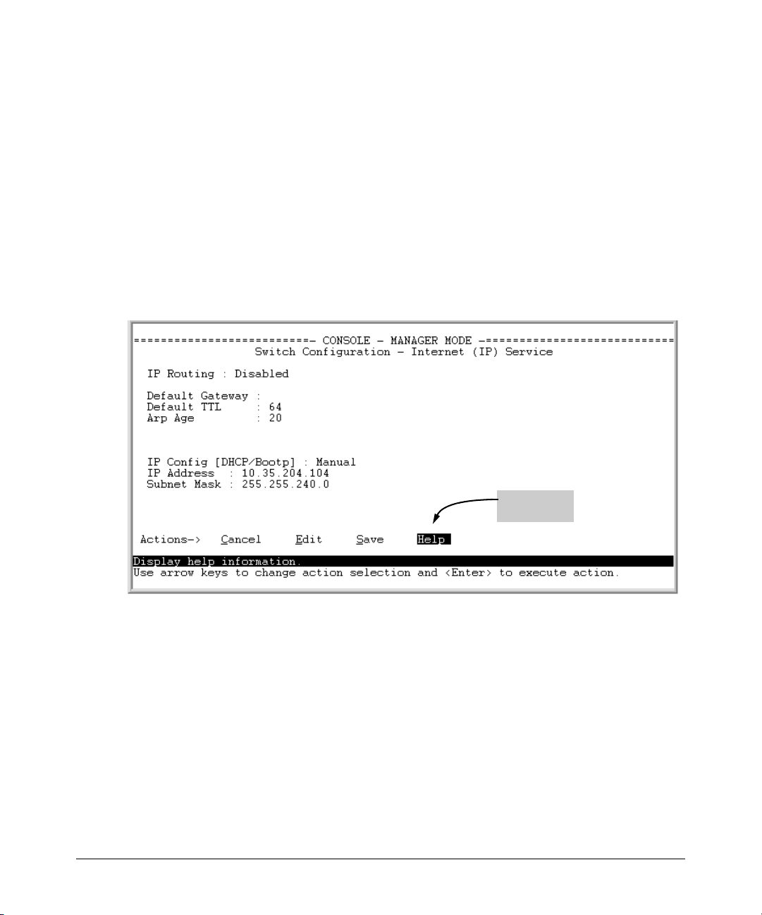
Menu Interface
If you need information on specific parameters in the menu interface, refer to
the online help provided in the interface. For example:
1-6
Online Help
for Menu
Figure 1-2. Online Help for Menu Interface
Page 27
Need Only a Quick Start?
Getting Started
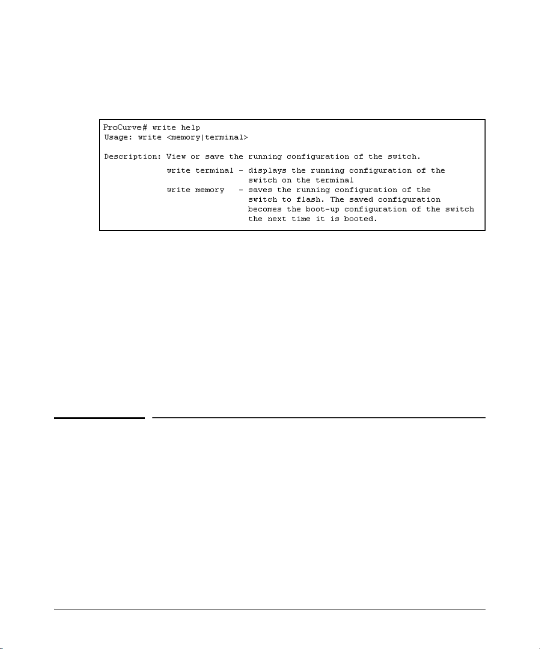
Command Line Interface
If you need information on a specific command in the CLI, type the command
name followed by help. For example:
Figure 1-3. Example of CLI Help
WebAgent (Web Browser Interface)
If you need information on specific features in the HP ProCurve WebAgent,
use the online Help. You can access the Help by clicking on the “Help” text in
any WebAgent screen.
To download the WebAgent help files to a local server, go to:
www.hp.com/rnd/device_help/download.htm
Follow the directions on the web page to download the WebAgent help for
your device.
Need Only a Quick Start?
IP Addressing
If you just want to give the switch an IP address so that it can communicate
on your network, or if you are not using VLANs, ProCurve recommends that
you use the Switch Setup screen to quickly configure IP addressing. To do so,
do one of the following:
■ Enter setup at the CLI Manager level prompt.
Procurve# setup
1-7
Page 28

Getting Started
To Set Up and Install the Switch in Your Network
■ In the Main Menu of the Menu interface select
8. Run Setup
For more on using the Switch Setup screen, see the Installation and Getting
Started Guide you received with the switch.
To Set Up and Install the Switch in Your
Network
Physical Installation
Use the Installation and Getting Started Guide for the following:
■ Notes, cautions, and warnings related to installing and using the switch
and its related modules
■ Instructions for physically installing the switch in your network
■ Quickly assigning an IP address and subnet mask, set a Manager pass-
word, and (optionally) configure other basic features.
■ Interpreting LED behavior.
1-8
For the latest version of the Installation and Getting Started Guide for your
switch, refer to “Getting Documentation From the Web” on page 1-6.
1
Page 29

Introduction to IPv6
Contents
Migrating to IPv6 . . . . . . . . . . . . . . . . . . . . . . . . . . . . . . . . . . . . . . . . . . . . . 2-3
IPv6 Propagation . . . . . . . . . . . . . . . . . . . . . . . . . . . . . . . . . . . . . . . . . . . . 2-4
Dual-Stack Operation . . . . . . . . . . . . . . . . . . . . . . . . . . . . . . . . . . . . . . . . 2-4
Connecting to Devices Supporting IPv6 Over IPv4 Tunneling . . . . . . 2-5
Information Sources for Tunneling IPv6 Over IPv4 . . . . . . . . . . . 2-5
Use Model . . . . . . . . . . . . . . . . . . . . . . . . . . . . . . . . . . . . . . . . . . . . . . . . . . . . 2-6
Adding IPv6 Capability . . . . . . . . . . . . . . . . . . . . . . . . . . . . . . . . . . . . . . . 2-6
Supported IPv6 Operation . . . . . . . . . . . . . . . . . . . . . . . . . . . . . . . . . . . . 2-6
Configuration and Management . . . . . . . . . . . . . . . . . . . . . . . . . . . . . . . . 2-7
Management Features . . . . . . . . . . . . . . . . . . . . . . . . . . . . . . . . . . . . . . . 2-7
IPv6 Addressing . . . . . . . . . . . . . . . . . . . . . . . . . . . . . . . . . . . . . . . . . . . . . 2-7
SLAAC (Stateless Automatic Address Configuration) . . . . . . . . . 2-7
DHCPv6 (Stateful) Address Configuration . . . . . . . . . . . . . . . . . . . 2-8
Static Address Configuration . . . . . . . . . . . . . . . . . . . . . . . . . . . . . . 2-8
Default IPv6 Gateway . . . . . . . . . . . . . . . . . . . . . . . . . . . . . . . . . . . . 2-8
Neighbor Discovery (ND) in IPv6 . . . . . . . . . . . . . . . . . . . . . . . . . . . . . . 2-9
IPv6 Management Features . . . . . . . . . . . . . . . . . . . . . . . . . . . . . . . . . . 2-10
TFTPv6 Transfers . . . . . . . . . . . . . . . . . . . . . . . . . . . . . . . . . . . . . . . 2-10
IPv6 Time Configuration . . . . . . . . . . . . . . . . . . . . . . . . . . . . . . . . . 2-10
Telnet6 . . . . . . . . . . . . . . . . . . . . . . . . . . . . . . . . . . . . . . . . . . . . . . . . 2-10
IP Preserve . . . . . . . . . . . . . . . . . . . . . . . . . . . . . . . . . . . . . . . . . . . . 2-11
Multicast Listener Discovery (MLD) . . . . . . . . . . . . . . . . . . . . . . . 2-11
Web Browser Interface . . . . . . . . . . . . . . . . . . . . . . . . . . . . . . . . . . 2-11
Path MTU (PMTU) Discovery . . . . . . . . . . . . . . . . . . . . . . . . . . . . . . . . 2-11
2
Configurable IPv6 Security . . . . . . . . . . . . . . . . . . . . . . . . . . . . . . . . . . . 2-12
SSHv2 on IPv6 . . . . . . . . . . . . . . . . . . . . . . . . . . . . . . . . . . . . . . . . . . . . . 2-12
IP Authorized Managers . . . . . . . . . . . . . . . . . . . . . . . . . . . . . . . . . . . . . 2-12
2-1
Page 30

Introduction to IPv6
Contents
Diagnostic and Troubleshooting . . . . . . . . . . . . . . . . . . . . . . . . . . . . . . . 2-14
ICMP Rate-Limiting . . . . . . . . . . . . . . . . . . . . . . . . . . . . . . . . . . . . . . . . . 2-14
Ping6 . . . . . . . . . . . . . . . . . . . . . . . . . . . . . . . . . . . . . . . . . . . . . . . . . . . . . 2-14
Traceroute6 . . . . . . . . . . . . . . . . . . . . . . . . . . . . . . . . . . . . . . . . . . . . . . . 2-14
Debug/Syslog Enhancements . . . . . . . . . . . . . . . . . . . . . . . . . . . . . . . . 2-14
Domain Name System (DNS) Resolution . . . . . . . . . . . . . . . . . . . . . . . 2-14
IPv6 Neighbor Discovery (ND) Controls . . . . . . . . . . . . . . . . . . . . . . . 2-15
Event Log . . . . . . . . . . . . . . . . . . . . . . . . . . . . . . . . . . . . . . . . . . . . . . . . . 2-15
SNMP . . . . . . . . . . . . . . . . . . . . . . . . . . . . . . . . . . . . . . . . . . . . . . . . . . . . 2-15
Loopback Address . . . . . . . . . . . . . . . . . . . . . . . . . . . . . . . . . . . . . . . . . . 2-15
IPv6 Scalability . . . . . . . . . . . . . . . . . . . . . . . . . . . . . . . . . . . . . . . . . . . . . . 2-16
2-2
Page 31
Introduction to IPv6
Migrating to IPv6
Migrating to IPv6
To successfully migrate to IPv6 involves maintaining compatibility with the
large installed base of IPv4 hosts and routers for the immediate future. To
achieve this purpose, software release K.13.01 and greater supports dual-stack
(IPv4/IPv6) operation and connections to IPv6-aware routers for routing IPv6
traffic between VLANs and across IPv4 networks.
Note Beginning with release K.13.01 the software supports traffic connections with
IPv6-aware routers, but does not support IPv6 routing operation in the
switches covered by this guide.
Beginning with software release K.13.01, the switches covered by this guide
support the following IPv6 protocol operations:
■ receiving IPv6 traffic addressed to the switch
■ transmitting IPv6 traffic originating on the switch
■ switching IPv6 traffic between IPv6 devices connected to the switch on
the same VLAN
■ concurrent (dual-stack) operation with IPv4 traffic and devices on the
same VLAN
■ using a connection to an external, IPv6-configured router, forward IPv6
traffic intended for devices on other VLANs and for traffic that must
traverse an IPv4 network to reach an IPv6 destination
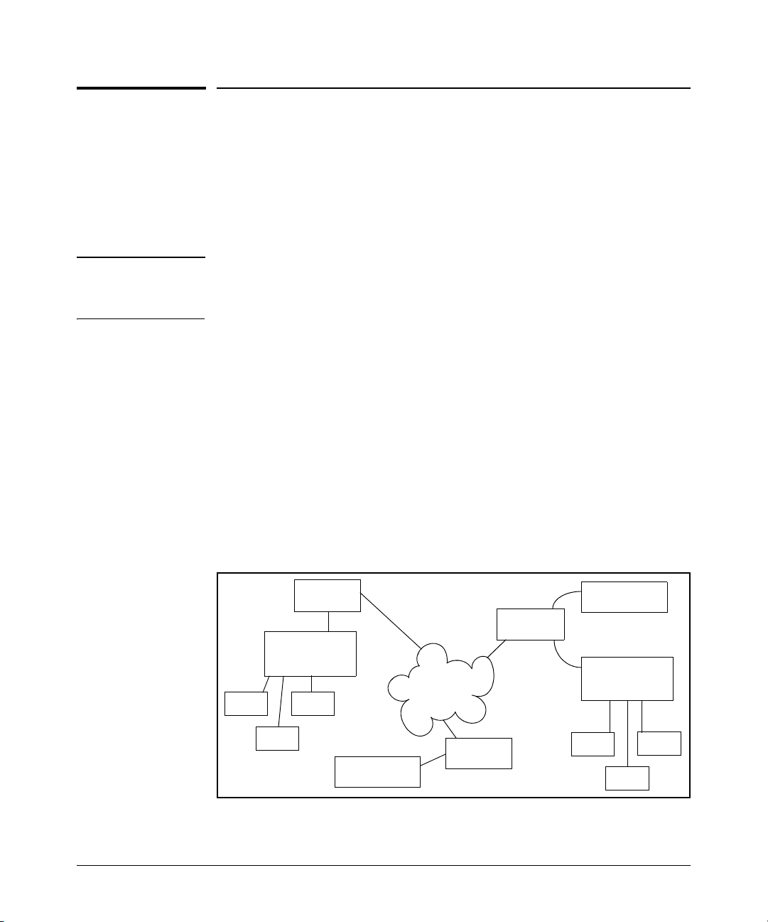
H1
IPv6/IPv4
Router
ProCurve
Switch Running
Release K.13.01
H2
H3
IPv6-Capable
DNS Server
IPv6/IPv4
Router
IPv4 Network
IPv6/IPv4
Router
DHCPv6
Server
ProCurve
Switch Running
Release K.13.01
H4
H6
H5
Figure 2-1. Dual-Stack ProCurve Switches Employed in an IPv4/IPv6 Network
2-3
Page 32

Introduction to IPv6
Migrating to IPv6
IPv6 Propagation
IPv6 is currently in the early stages of deployment worldwide, involving a
phased-in migration led by the application of basic IPv6 functionality. In these
applications, IPv6 traffic is switched among IPv6-capable devices on a given
LAN, and routed between LANs using IPv6-capable routers. Using the IPv6
features in this software release, the switch can operate in an IPv6 network,
be managed using an IPv6 management station, and interact with DHCPv6 and
IPv6-enabled DNS servers in the same network or accessible through a
connection to an IPv6 router.
Dual-Stack Operation
Since most initial IPv6 deployments are in networks having a mixture of IPv6
and IPv4 hosts, software releases K.13.01 and greater support dual- stack IPv4/
IPv6 operation. This enables the switch to communicate individually with IPv4
and IPv6 devices with their respective protocols. Thus, IPv4 and IPv6 traffic
is supported simultaneously on the same VLAN interface. This means that both
IPv4 and IPv6 devices can operate at the same time on a given VLAN.
Note Software releases K.13.01 and greater do not include gateways for translation
between IPv6 and IPv4 traffic. While IPv4 and IPv6 traffic coexists on the same
VLAN, the individual IPv4 and IPv6 devices ignore each other's traffic.
2-4
To forward IPv6 traffic from the switch to an IPv6-capable device on a different
VLAN, a link to an external IPv6-capable router is needed. Also, IPv6 traffic
movement from the switch over IPv4 paths requires routers capable of IPv6
over IPv4 tunneling.
Page 33

Introduction to IPv6
Migrating to IPv6
Connecting to Devices Supporting IPv6 Over IPv4 Tunneling
The switches covered by this guide can interoperate with IPv6/IPv4 devices
capable of tunneling IPv6 traffic across an IPv4 infrastructure. Some examples
include:
■ traffic between IPv6/IPv4 routers (router/router)
■ traffic between an IPv6/IPv4 router and an IPv6/IPv4 host capable of
tunneling (router/host)
Note Tunneling requires an IPv6-capable router. A switch running software release
K.13.01 or greater does not route or tunnel IPv6 traffic. To enable IPv6 traffic
from the switch to be routed or to be tunneled across an IPv4 network, it is
necessary to connect the switch to an appropriate IPv6-capable router. For
more information, refer to the documentation provided with the dual- stack
(IPv4/IPv6) routers you plan to use for this purpose.
IPv6 tunneling eases IPv6 deployment by maintaining compatibility with the
large existing base of IPv4 hosts and routers. Generally, the various IPv6
tunneling methods enable IPv6 hosts and routers to connect with other IPv6
hosts and routers over the existing IPv4 Internet.
Information Sources for Tunneling IPv6 Over IPv4
For more information on IPv6 routing and tunneling, refer to the documentation provided with the IPv6/IPv4 routing and tunneling-capable devices in your
network. Some other sources of information are:
■ RFC 2893: “Transition Mechanisms for IPv6 Hosts and Routers”
■ RFC 2401: “Security Architecture for the Internet Protocol”
■ RFC 2473: “Generic Packet Tunneling in IPv6 Specification”
■ RFC 2529: “Transmission of IPv6 via IPv4 Domains without Explicit
Tunnels”
■ RFC 3056: “Connection of IPv6 Domains Over IPv4 Clouds”
2-5
Page 34

Introduction to IPv6
Use Model
Use Model
Adding IPv6 Capability
IPv6 was designed by the Internet Engineering Task Force (IETF) to improve
on the scalability, security, ease of configuration, and network management
capabilities of IPv4.
IPv6 provides increased flexibility and connectivity for existing networked
devices, addresses the limited address availability inherent in IPv4, and the
infrastructure for the next wave of Internet devices, such as PDAs, mobile
phones and appliances.
Where IPv4 networks exist today, IPv6 will be phased in over a period of years,
requiring an interoperability among the devices using the two protocols.
Beginning with software release K.13.01, the switches covered by this guide
support IPv4/IPv6 dual stack operation. This allows full ethernet link support
for both IPv4 and IPv6 traffic to move on the same interface (VLAN) without
modifying current IPv4 network topologies. This enables you to use IPv6
devices on existing VLANs, manage the switch and other devices from IPv6
management stations, and create groups of dedicated IPv6 devices as needed
to accommodate the anticipated IPv6 network growth.
2-6
Supported IPv6 Operation
Software releases K.13.01 and greater provide IPv6 protocol and addressing
to support host-mode (endpoint) IPv6 operation, including basic layer-2 functionality. IPv6 routing features are not available in this release. However, using
a dual-stack (IPv4/IPv6-capable) router, IPv6 traffic can be routed between
VLANs and sent across an IPv4 network to another IPv6 device.
(For general information on sending IPv6 traffic across an IPv4 network, refer
to “Connecting to Devices Supporting IPv6 Over IPv4 Tunneling” on page 2-5.)
The next three sections outline the IPv6 features supported in software release
K.13.01 and greater. These features are categorized as follows:
■ configuration and management
■ security
■ IPv6 multicast traffic
■ diagnostic and troubleshooting
Page 35

Configuration and Management
Introduction to IPv6
Configuration and Management
This section outlines the configurable management features supporting IPv6
operation on your ProCurve IPv6-ready switch.
Management Features
Software releases K.13.01and greater provide host-based IPv6 features that
enable the switches covered in this guide to be managed from an IPv6
management station and to operate in both IPv6 and IPv4/IPv6 network
environments.
Note Software releases K.13.01 and greater do not include IPv6 routing, but inter-
operate with routers that support IPv6 and IPv4/IPv6 router applications.
IPv6 Addressing
The switch offers these IPv6 address configuration features:
■ SLAAC (stateless automatic address configuration)
■ DHCPv6 (stateful automatic address configuration)
■ static address configuration
SLAAC (Stateless Automatic Address Configuration)
Enabling IPv6 on a VLAN automatically enables configuration of a link-local
unicast IPv6 address on the VLAN. (No DHCPv6 server is needed.) This
address begins with the hexadecimal prefix fe80, which is prepended to the
interface identifier part of the address. (The interface identifier is generated
from the MAC address of the VLAN itself, using the 64-bit extended unique
identifier (EUI) method.) This enables the IPv6 nodes on the VLAN to
configure and manage the switch.
Enabling IPv6 address auto configuration on a VLAN automatically enables
automatic configuration of global unicast addresses on the VLAN. After
enabling auto configuration, a router advertisement (RA) containing an
assigned global address prefix must be received on the VLAN from an IPv6
router on the same VLAN. The resulting address is a combination of the prefix
and the interface identifier currently in use in the link-local address. Having a
global unicast address and a connection to an IPv6- aware router enables IPv6
2-7
Page 36

Introduction to IPv6
Configuration and Management
traffic on a VLAN to be routed to other VLANs supporting IPv6-aware devices.
(Using software release K.13.01 or greater, an external, IPv6-aware router is
required to forward traffic between VLANs.)
Multiple, global unicast addresses can be configured on a VLAN that receives
RAs specifying different prefixes.
DHCPv6 (Stateful) Address Configuration
The IPv6 counterpart to DHCP client for IPv4 operation is DHCPv6. Global
unicast addresses of any scope can be assigned, along with NTP (timep) server
addressing when DHCPv6 server support is available through either of the
following modes:
■ accessible on a VLAN configured on the switch
■ accessible through a connection to a router configured with DHCP relay
IPv6 also allows the option of using stateless auto configuration or static
configuration to assign unicast addresses to a VLAN, while using a DHCPv6
server for time server addressing.
Static Address Configuration
Statically configuring IPv6 addresses provides flexibility and control over the
actual address values used on an interface. Also, if a statically configured linklocal address is configured on a static VLAN, the global addresses configured
on the VLAN as the result of router advertisements uses the device identifier
included in the link-local address. Statically configuring an IPv6 address on a
VLAN enables IPv6 on the VLAN if it has not already been enabled.
Default IPv6 Gateway
Instead of using static or DHCPv6 configuration, a default IPv6 gateway for
an interface (VLAN) is determined from the default router list of reachable or
probably reachable routers the switch detects from periodic multicast router
advertisements (RAs) received on the interface. For a given interface, there
can be multiple default gateways, with different nodes on the link using
different gateways. If the switch does not detect any IPv6 routers that are
reachable from a given interface, it assumes (for that interface) that it can
reach only the other devices connected to the interface.
Note In IPv6 for the switches covered in this guide, the default route cannot be
statically configured. Also, DHCPv6 does not include default route configuration.)
2-8
Page 37

Configuration and Management
Introduction to IPv6
Refer to “Default IPv6 Router” on page 4-29 and “View IPv6 Gateway, Route,
and Router Neighbors ” on page 4-30.
Neighbor Discovery (ND) in IPv6
The IPv6 Neighbor Discovery protocol operates in a manner similar to the IPv4
ARP protocol to provide for discovery of IPv6 devices such as other switches,
routers, management stations, and servers on the same interface. Neighbor
Discovery runs automatically in the default configuration and provides
services in addition to those provided in IPv4 by ARP. For example:
■ Run Duplicate Address Detection (DAD) to detect duplicate unicast
address assignments on an interface. An address found to be a duplicate
is not used, and the show ipv6 command displays the address as a duplicate.
■ Quickly identify routers on an interface by sending router solicitations
requesting an immediate router advertisement (RA) from reachable
routers.
■ If a default router becomes unreachable, locate an alternate (if available
on the interface).
■ Learn from reachable routers on the interface whether to use DHCPv6 or
stateless address auto configuration. In the latter case, this also includes
the address prefixes to use with stateless address auto configuration for
routed destinations. (A DHCPv6 server can also be used for “stateless”
service; that is, for configuring the interface for access to other network
services, but not configuring a global IPv6 unicast address on the interface. Refer to “Neighbor Discovery (ND)” on page 4-16.)
■ Use multicast neighbor solicitations to learn the link-layer addresses of
destinations on the same interface and to verify that neighbors to which
traffic is being sent are still reachable.
■ Send a multicast neighbor advertisement in response to a solicitation from
another device on the same interface or to notify neighbors of a change
in the link- layer address.
■ Determine the MTU (Maximum Transmission Unit) for the interface from
router advertisements.
For more on IPv6 neighbor discovery applications, refer to “Neighbor
Discovery (ND)” on page 4-16.
2-9
Page 38

Introduction to IPv6
Configuration and Management
IPv6 Management Features
The switch's IPv6 management features support operation in an environment
employing IPv6 servers and management stations.With a link to a properly
configured IPv6 router, switch management extends to routed traffic solutions. (Refer to the documentation provided for the IPv6 router.) Otherwise,
IPv6 management for the switches covered by this guide are dependent on
switched management traffic solutions.
TFTPv6 Transfers
The switch supports these downloads from an IPv6 TFTP server:
■ automatic OS download
■ manual OS download
■ command script download and execution
■ configuration file downloads
■ public key file downloads
■ startup configuration file downloads
The switch supports these uploads to an IPv6 TFTP server
■ startup or running configuration upload
■ OS upload from flash in current use (primary or secondary)
■ event log content upload
■ crash log content upload
■ output of a specified command
2-10
Refer to “TFTP File Transfers Over IPv6” on page 5-17.
IPv6 Time Configuration
The switch supports both Timepv6 and SNTPv6 time services. Refer to “SNTP
and Timep” on page 5-10.
Telnet6
The switch supports both of the following Telnet6 operations:
■ Enable (the default setting) or disable Telnet6 access to the switch from
remote IPv6 nodes.
■ Initiate an outbound telnet session to another IPv6 networked device.
Refer to “IPv6 Telnet Operation” on page 5-6
Page 39

Configuration and Management
Introduction to IPv6
IP Preserve
IP Preserve operation preserves both the IPv4 and IPv6 addresses configured
on VLAN 1 (the default VLAN) when a configuration file is downloaded to the
switch using TFTP. Refer to “IP Preserve for IPv6” on page 5-28.
Multicast Listener Discovery (MLD)
MLD operates in a manner similar to IGMP in IPv4 networks. In the factory
default state (MLD disabled), the switch floods all IPv6 multicast traffic it
receives on a given VLAN through all ports on that VLAN except the port
receiving the inbound multicast traffic. Enabling MLD imposes management
controls on IPv6 multicast traffic to reduce unnecessary bandwidth usage.
MLD is configured per- VLAN. For information on MLD, refer to the chapter
titled “Multicast Listener Discovery (MLD) Snooping”.
Web Browser Interface
For the web browser interface, software releases K.13.01 and greater add the
following IPv6 functionality:
■ configure and display IPv6 addressing
■ ping6 diagnostic operation
Path MTU (PMTU) Discovery
IPv6 PMTU operation is managed automatically by the IPv6 nodes between
the source and destination of a transmission. For Ethernet frames, the default
MTU is 1500 bytes. If a router on the path cannot forward the default MTU
size, it sends an ICMPv6 message (PKT_TOO_BIG) with the recommended
MTU to the sender of the frame. If the sender of the frame is an IPv6 node that
supports PMTU discovery, it will then use the MTU specified by the router and
cache it for future reference.
For related information, refer to:
■ RFC 1981: “Path MTU Discovery for IP version 6”
2-11
Page 40

Introduction to IPv6
Configurable IPv6 Security
Configurable IPv6 Security
This section outlines the configurable IPv6 security features supported in
software release K.14.01.
SSHv2 on IPv6
SSHv2 provides for the authentication between clients and servers, and
protection of data integrity, and privacy. It is used most often to provide a
secure alternative to Telnet and is also used for secure file transfers (SFTP
and SCP). Beginning with software release K.13.01, SSH functionality is
supported on ProCurve switches running either IPv4 or IPv6. Beginning with
software release K.14.01, when SSH operation is enabled (the default setting),
it automatically runs for both IPv4 and IPv6 traffic.
The switch supports up to six inbound sessions of the following types in any
combination at any given time:
■ SSHv2
■ SSHv2 IPv6
■ Telnet-server
■ Telnet6-server
■ SFTP/SCP (One SFTP or SCP session allowed at a given time.)
■ Console (serial RS-232 connection)
2-12
For more information, refer to “Secure Shell (SSH) for IPv6” on page 6-15.
IP Authorized Managers
The IPv6 Authorized IP Managers feature, like the IPv4 version, uses IP
addresses and masks to determine which stations (PCs and workstations) can
access the switch through the network, and includes these access methods:
■ Telnet, SSH, and other terminal emulation applications
■ the switch's web browser interface
■ SNMP (with a correct community name)
Also, when configured in the switch, the access control imposed by the
Authorized IP Manager feature takes precedence over the other forms of
access control configurable on the switch, such as local passwords, RADIUS,
and both Port-Based and Client-Based Access Control (802.1X). This means
Page 41

Introduction to IPv6
Configurable IPv6 Security
that the IP address of a networked management device must be authorized
before the switch will attempt to authenticate the device by invoking any other
access security features. Thus, with Authorized IP Managers configured,
having the correct passwords or MAC address is not sufficient for accessing
the switch through the network unless an IPv6 address configured on the
station attempting the access is also included in the switch's Authorized IP
Managers configuration. This presents the opportunity to combine the Authorized IP Managers feature with other access control features to enhance the
security fabric protecting the switch.
Caution The Authorized IP Managers feature does not protect against unauthorized
station access through a modem or direct connection to the Console (RS-232)
port. Also, if an unauthorized station “spoofs” an authorized IP address, then
the unauthorized station cannot be blocked by the Authorized IP Managers
feature, even if a duplicate IP address condition exists.
To configure authorized IPv6 managers, refer to “Authorized IP Managers for
IPv6” on page 6-3.
For related information, refer to:
■ RFC 4864, “Local Network Protection for IPv6”.
2-13
Page 42

Introduction to IPv6
Diagnostic and Troubleshooting
Diagnostic and Troubleshooting
Software releases K.13.01 and greater include the IPv6 diagnostic and troubleshooting features listed in this section.
ICMP Rate-Limiting
Controlling the frequency of ICMPv6 error messages can help to prevent DoS
(Denial- of- Service) attacks. With IPv6 enabled on the switch, you can control
the allowable frequency of these messages with ICMPv6 rate-limiting. Refer
to “ICMP Rate-Limiting” on page 9-2.
Ping6
Implements the Ping protocol for IPv6 destinations, and includes the same
options as are available for IPv4 Ping, including DNS hostnames. Refer to
“Ping for IPv6 (Ping6)” on page 9-4.
Traceroute6
Implements Traceroute for IPv6 destinations, and includes the same options
as are available for the IPv4 Traceroute, including DNS hostnames. Refer to
“Traceroute for IPv6” on page 9-7.
Debug/Syslog Enhancements
Includes new options for IPv6. Refer to “Debug/Syslog for IPv6” on page 9-13.
Domain Name System (DNS) Resolution
This feature enables resolving a host name to an IPv6 address and the reverse,
and takes on added importance over its IPv4 counterpart due to the extended
length of IPv6 addresses. With DNS-compatible commands, CLI command
entry becomes easier for reaching a device whose IPv6 address is configured
with a host name counterpart on a DNS server.
Software release K.13.01 includes the following DNS-compatible commands:
■ ping6
■ traceroute6
2-14
Page 43

Diagnostic and Troubleshooting
The switches covered by this guide now support a prioritized list of up to three
DNS server addresses. (Earlier software releases supported only one DNS
server address.) Also, the server address list can include both IPv4 and IPv6
DNS server addresses. (An IPv6 DNS server can respond to IPv4 queries, and
the reverse.)
Introduction to IPv6
Note If an IPv6 DNS server address is configured on the switch, at least one VLAN
on the switch (and in the path to the DNS server) must be configured with an
IPv6 address.
For information on configuring DNS resolution on the switch, refer to “DNS
Resolver for IPv6” on page 9-10.
IPv6 Neighbor Discovery (ND) Controls
The neighbor discovery feature includes commands for:
■ increasing or decreasing the frequency of Duplicate Address Detection
searches
■ displaying the IPv6 neighbor cache
■ clearing dynamic entries from the neighbor cache
Refer to “Neighbor Discovery (ND) in IPv6” on page 2-9.
Event Log
Messages returning IP addresses now include IPv6 addresses where applicable.
SNMP
When IPv6 is enabled on a VLAN interface, you can manage the switch from
a network management station configured with an IPv6 address. Refer to
“SNMP Management for IPv6” on page 5-24.
Loopback Address
Like the IPv4 loopback address, the IPv6 loopback address (::1) can be used
by the switch to send an IPv6 packet to itself. However, the IPv6 loopback
address is implicit on a VLAN and cannot be statically configured on any
VLAN. Refer to “Loopback Address” on page 3-23.
2-15
Page 44

Introduction to IPv6
IPv6 Scalability
IPv6 Scalability
As of software release K.14.01, the switches covered by this guide support the
following:
■ Dual stack operation (IPv4 and IPv6 addresses on the same VLAN).
■ per-switch
VLANs, maximum configured 2048
VLANs, maximum with IPv4 and 512
IPv6 addresses in any combination
IP addresses IPv4: 2048
IPv6 user-configured: 2048
IPv6 auto-configured: 2048*
IP addresses per-VLAN IPv4: 32
IPv6 user-configured: 32
IPv6 auto-configured, prefix based: 3
2-16
IPv6 routes 25,000
*Auto-configured link-local and prefix-based addresses.
■ Maximum of 2048 active IPv6 addresses on the switch, in addition to a
maximum of 2048 IPv4 addresses. (“Active IPv6 addresses” includes the
total of all preferred and non-preferred addresses configured statically,
through DHCPv6, and through stateless auto configuration. Excluded
from “Active IPv6 Addresses” is the link-local address assigned to each
VLAN, and “on- link” prefixes received as part of a router advertisement.)
■ Maximum of 25,000 IPv6 routes.
For more information on VLAN and route scalability on the switches covered
by this guide, refer to the appendix titled “Scalability: IP Address, VLAN, and
Routing Maximum Values” in the Management and Configuration Guide for
your switch.
Page 45

IPv6 Addressing
Contents
Introduction . . . . . . . . . . . . . . . . . . . . . . . . . . . . . . . . . . . . . . . . . . . . . . . . . . 3-3
IPv6 Address Structure and Format . . . . . . . . . . . . . . . . . . . . . . . . . . . . 3-3
Address Format . . . . . . . . . . . . . . . . . . . . . . . . . . . . . . . . . . . . . . . . . 3-3
Address Notation . . . . . . . . . . . . . . . . . . . . . . . . . . . . . . . . . . . . . . . . 3-3
Network Prefix . . . . . . . . . . . . . . . . . . . . . . . . . . . . . . . . . . . . . . . . . . 3-4
Interface (Device) Identifier . . . . . . . . . . . . . . . . . . . . . . . . . . . . . . . 3-4
IPv6 Addressing Options . . . . . . . . . . . . . . . . . . . . . . . . . . . . . . . . . . . . . . . 3-5
IPv6 Address Sources . . . . . . . . . . . . . . . . . . . . . . . . . . . . . . . . . . . . . . . . 3-5
General IPv6 Address Types . . . . . . . . . . . . . . . . . . . . . . . . . . . . . . . . . . 3-5
IPv6 Address Sources . . . . . . . . . . . . . . . . . . . . . . . . . . . . . . . . . . . . . . . . . 3-7
Stateless Address Autoconfiguration (SLAAC) . . . . . . . . . . . . . . . . . . . 3-7
Applications . . . . . . . . . . . . . . . . . . . . . . . . . . . . . . . . . . . . . . . . . . . . 3-7
Preferred and Valid Lifetimes of Stateless Autoconfigured
Addresses . . . . . . . . . . . . . . . . . . . . . . . . . . . . . . . . . . . . . . . . . . . . . . 3-7
Stateful (DHCPv6) Address Configuration . . . . . . . . . . . . . . . . . . . . . . 3-8
Static Address Configuration . . . . . . . . . . . . . . . . . . . . . . . . . . . . . . . . . . 3-9
3
Address Types and Scope . . . . . . . . . . . . . . . . . . . . . . . . . . . . . . . . . . . . . 3-10
Address Types . . . . . . . . . . . . . . . . . . . . . . . . . . . . . . . . . . . . . . . . . . . . . 3-10
Address Scope . . . . . . . . . . . . . . . . . . . . . . . . . . . . . . . . . . . . . . . . . . . . . 3-10
Unicast Address Prefixes . . . . . . . . . . . . . . . . . . . . . . . . . . . . . . . . . . . . 3-11
Link-Local Unicast Address . . . . . . . . . . . . . . . . . . . . . . . . . . . . . . . . . . . 3-13
Autoconfiguring Link-Local Unicast Addresses . . . . . . . . . . . . . . . . . 3-13
Extended Unique Identifier (EUI) . . . . . . . . . . . . . . . . . . . . . . . . . . . . . 3-14
Statically Configuring Link-Local Addresses . . . . . . . . . . . . . . . . . . . . 3-15
Global Unicast Address . . . . . . . . . . . . . . . . . . . . . . . . . . . . . . . . . . . . . . . 3-16
Stateless Autoconfiguration of a Global Unicast Address . . . . . . . . . 3-16
Static Configuration of a Global Unicast Address . . . . . . . . . . . . . . . 3-17
3-1
Page 46

IPv6 Addressing
Contents
Prefixes in Routable IPv6 Addresses . . . . . . . . . . . . . . . . . . . . . . . . . . 3-18
Unique Local Unicast IPv6 Address . . . . . . . . . . . . . . . . . . . . . . . . . . . . 3-19
Multicast Application to IPv6 Addressing . . . . . . . . . . . . . . . . . . . . . . 3-19
Overview of the Multicast Operation in IPv6 . . . . . . . . . . . . . . . . . . . . 3-20
IPv6 Multicast Address Format . . . . . . . . . . . . . . . . . . . . . . . . . . . . . . . 3-20
Multicast Group Identification . . . . . . . . . . . . . . . . . . . . . . . . . . . . 3-21
Solicited-Node Multicast Address Format . . . . . . . . . . . . . . . . . . 3-22
Loopback Address . . . . . . . . . . . . . . . . . . . . . . . . . . . . . . . . . . . . . . . . . . . . 3-23
The Unspecified Address . . . . . . . . . . . . . . . . . . . . . . . . . . . . . . . . . . . . . 3-23
IPv6 Address Deprecation . . . . . . . . . . . . . . . . . . . . . . . . . . . . . . . . . . . . 3-24
Preferred and Valid Address Lifetimes . . . . . . . . . . . . . . . . . . . . . . . . . 3-24
3-2
Page 47

IPv6 Addressing
Introduction
Introduction
IPv6 supports multiple addresses on an interface, and uses them in a manner
comparable to subnetting an IPv4 VLAN. For example, where the switch is
configured with multiple VLANs and each is connected to an IPv6 router, each
VLAN will have a single link-local address and one or more global unicast
addresses. This section describes IPv6 addressing and outlines the options for
configuring IPv6 addressing on the switch. The configuration process includes
automatically or statically creating an IPv6 address and automatically verifying the uniqueness of each.
IPv6 Address Structure and Format
Address Format
An IPv6 address is composed of 128 bits divided into eight 2-byte fields of
hexadecimal values. The full format is:
xxxx : xxxx : xxxx : xxxx : xxxx : xxxx : xxxx : xxxx
where each field delimited by a colon (:) is a set of four hexadecimal digits.
For example:
2001:0db8:0000:00A9:0215:60ff:fe7a:adc0
2001:0db8:0260:0212:0000:0000:0000:01b4
The hexadecimal characters in IPv6 addresses are not case-sensitive.
Address Notation
Leading zeros in each field can be omitted as long as each field is represented
by at least one value. The exception to this rule is when there is an uninterrupted series of zeros in one or more contiguous fields. In this case, the series
of zeros can be replaced by “::”, with the restriction that “::” can be used only
once in a given address. Applying this convention to the above examples
results in the following address notations:
2001:db8::a9:215:60ff:fe7a:adc0
2001:db8:260:0212::01b4
3-3
Page 48

IPv6 Addressing
IPv6 Address Structure and Format
An IPv6 address includes a network prefix and an interface identifier.
Network Prefix
The network prefix (high-order bits) in an IPv6 address begins with a wellknown, fixed prefix for defining the address type. Some examples of wellknown, fixed prefixes are:
2000::/3global (routable) unicast address
fd08::/8 unique local unicast address
fe80::/8 link-local unicast address
ff00::/8 multicast address
The remainder of the network prefix depends on the prefix type, and includes
information such as the subnet destination of unicast addresses or the flags
and scope of multicast addresses.
In a given address, CIDR-type notation (Classless Inter-Domain Routing) is
used to define the network prefix. In the following address example, the 64
bits comprising 2001:0db8:0260:0212 form the network prefix:
2001:0db8:0260:0212:0215:60ff:fe7a:adc0/64
3-4
A shorter way to show this address is to remove the leading zeros:
2001:db8:260:212:215:60ff:fe7a:adc0/64
Interface (Device) Identifier
The remaining (low-order) bits in the address comprise a unique interface
identifier in an IPv6 address. In the above example, the rightmost 64 bits
(215:60ff:fe7a:adc0) comprise the interface identifier. Unlike IPv4, an IPv6
identifier for a unicast address can be automatically generated from the
switch's MAC address using EUI-64 (Extended Unique Identifier) format.
Other methods include DHCPv6 assignments and static configuration. Interface identifiers are covered in more detail in the later sections of this chapter
describing different address types.
Page 49

IPv6 Addressing
IPv6 Addressing Options
IPv6 Addressing Options
IPv6 Address Sources
IPv6 addressing sources provide a flexible methodology for assigning
addresses to VLAN interfaces on the switch. Options include:
■ stateless IPv6 Autoconfiguration on VLAN interfaces includes:
• link-local unicast addresses
• global unicast addresses
■ stateful, global unicast IPv6 address configuration using DHCPv6
■ static IPv6 address configuration
You can combine stateless, stateful, and static IP addressing methods on the
switch as needed, according to the needs in your network. For example, if
your network includes only one VLAN, you may need only stateless Autoconfiguration of link-local addresses, although you could also use the static IPv6
method. (DHCPv6 does not configure link-local addresses.) Where routed
traffic is used, you will also need global unicast addressing, either through
stateless Autoconfiguration or the other listed methods.
General IPv6 Address Types
IPv6 supports stateless and stateful address Autoconfiguration, as well as
static address configuration.This enables IPv6 to automatically address a
device so that it can be placed in a network with or without static or DHCPv6
addressing intervention. All three of these methods can be used exclusively
or in conjunction with each other, and a given IPv6 device can have multiple
addresses assigned to the same interface in a manner similar to subnetting in
IPv4.
Stateless Address Autoconfiguration. This method does not require the
use of servers. Instead, in the default operation, the host uses its MAC address
to automatically generate a link-local IPv6 address using the EUI-64 method
to generate the device identifier. (Refer to “Autoconfiguring Link-Local
Unicast Addresses” on page 3-13.) The scope of the link-local address enables
communication with other IPv6 devices on the same VLAN. If an IPv6 router
is present, an IPv6 address supporting routing is automatically generated, as
well. (The switch merges a router-generated prefix received in router advertisements with the last 64 bits of the link-local address on an interface to create
the global address.) Refer to page 3-7.
3-5
Page 50

IPv6 Addressing
IPv6 Addressing Options
Stateful Address Autoconfiguration. This method allows use of a
DHCPv6 server to automatically configure IPv6 addressing on a host in a
manner similar to stateful IP addressing with a DHCPv4 server. For software
releases K.13.01 and greater, a DHCPv6 server can provide routable IPv6
addressing and NTP (timep) server addresses. Also, if the host acquires its
IPv6 addressing through stateless or static methods, the DHCPv6 server can
still be used to automatically provide other configuration information to the
host. Refer to page 3-8.
Static Address Configuration. Static configuration is used instead of or in
addition to stateless and stateful Autoconfiguration where use of the host
MAC address does not provide the desired level of address control and
distribution. Refer to page 3-9.
Duplicate Address Detection (DAD). IPv6 verifies both the link-local and
the global unicast address(es) on each interface for uniqueness, regardless of
the method used to configure the address. If an address fails this test, it is
identified as a duplicate, and a replacement must be configured using the static
method. (To view address status, use the show ipv6 command.) For more
information on DAD, refer to “Neighbor Discovery (ND)” on page 4-16.
Developing an Addressing Plan. For small, flat networks and any environment where control of address assignments need not be restricted or tightly
controlled, stateless addressing is adequate for network management and
control. Where systematic and controlled addressing is needed, stateful and
static addressing methods should be used. Where dual-stack operation is used
in a VLAN, incorporating the local IPv4 addressing scheme into the IPv6
addresses you use can help to provide consistency and correspondence
among the IPv6 and IPv4 addresses in use on the VLAN.
Related Information.
■ RFC 4291: “IP Version 6 Addressing Architecture”
■ RFC 2462: “IPv6 Stateless Address Autoconfiguration”
■ RFC 3315: “Dynamic Host Configuration Protocol for IPv6 (DHCPv6)”
3-6
Page 51

IPv6 Addressing
IPv6 Address Sources
IPv6 Address Sources
IPv6 addressing sources provide a flexible methodology for assigning
addresses to VLAN interfaces on the switch. Options include:
■ stateless IPv6 Autoconfiguration on VLAN interfaces includes:
• link-local unicast addresses
• global unicast addresses
■ stateful IPv6 address configuration using DHCPv6
■ static IPv6 address configuration
You can combine stateless, stateful, and static IP addressing methods on the
switch as needed, according to the needs in your network. For example, if
your network includes only one VLAN, you may need only stateless Autoconfiguration of link-local addresses, although you could also use the static IPv6
method. (DHCPv6 does not configure link-local addresses.) Where routed
traffic is used, you will also need global unicast addressing, either through
stateless Autoconfiguration or the other listed methods.
Stateless Address Autoconfiguration (SLAAC)
On the switches covered by this guide, stateless address Autoconfiguration
(SLAAC) generates link-local unicast and global unicast IPv6 addresses on a
VLAN interface. In all cases, the prefix is 64 bits.
Applications
Stateless Autoconfiguration is suitable where a link-local or global unicast
IPv6 address (if a router is present) must be unique, but the actual address
used is not significant. Where a specific unicast address or a unicast address
from a specific range of choices is needed on an interface, DHCPv6 or static
IPv6 address configuration should be used. (Refer to pages 3-8 and 3-9.)
Preferred and Valid Lifetimes of Stateless Autoconfigured Addresses
The preferred and valid lifetimes of an Autoconfigured global unicast address
are set by the router advertisements (RA) used to generate the address, and
are the Autoconfiguration counterpart to the lease time assigned by DHCPv6
3-7
Page 52

IPv6 Addressing
IPv6 Address Sources
servers. These lifetimes cannot be reset using control from the switch console
or SNMP methods. Refer to “Preferred and Valid Address Lifetimes” on page 3-
24.
Stateful (DHCPv6) Address Configuration
Stateful addresses are defined by a system administrator or other authority,
and automatically assigned to the switch and other devices through the
Dynamic Host Configuration Protocol (DHCPv6). Generally, DHCPv6 should
be applied when you want specific, non-default addressing to be assigned
automatically. For IPv6, DHCP use is indicated for conditions such as the
following:
■ address conventions used in your network require defined control
■ static addressing is not feasible due to the number of nodes in the network
■ automatic assignment of multiple IPv6 addresses per interfaces is needed
■ automatic configuration of IPv6 access to DNS, SNTP, or TimeP servers
To implement stateful address configuration:
■ The DHCPv6 server must be configured and accessible to the switch,
either on the same VLAN or through an IPv6 router configured with DHCP
Relay to support service requests from the switch.
Note DHCPv6 relay may not currently be available in some IPv6 routers.
■ DHCPv6 addressing must be enabled per-VLAN on the switch.
Note that IPv6 router advertisements (RAs) can also include instructions to
clients to use DHCPv6 resources. Refer to the documentation for your IPv6
router.
If you want to use DHCPv6 in a dual-stack environment, you will need both
DHCPv4 and DHCPv6 server access. Also, further developments in DHCP
services are likely to mean new capabilities affecting DHCPv6 deployments.
For related information, refer to:
■ RFC 3315: “Dynamic Host Configuration Protocol for IPv6 (DHCPv6)”
■ RFC 3041: “Privacy Extensions for Stateless Address Autoconfiguration
in IPv6”
3-8
Page 53

IPv6 Addressing
IPv6 Address Sources
Static Address Configuration
Generally, static address configuration should be used when you want
specific, non-default addressing to be assigned to a VLAN interface. For IPv6,
DHCP use is indicated for conditions such as the following:
■ address conventions used in your network require defined control
■ the task of static addressing is not so extensive as to be impractical due
to the number of addresses and/or interfaces needing configuration
If IPv6 is not already enabled on a VLAN interface, the following is true:
■ Statically configuring a link-local address on the interface also enables
IPv6.
■ Statically configuring a global unicast address also enables IPv6 and
generates a link-local address.
Statically configured global unicast addresses can be used in addition to
stateless addresses on the same interface. However, because only one linklocal address is allowed on a VLAN interface (fe80::), static configuration of
a link-local address automatically replaces an existing link-local address.
Note For a statically configured global unicast address to be routable, a gateway
router must be transmitting router advertisements on the VLAN that include
the prefix used in the statically configured address. If the VLAN is not receiving
an RA with this prefix, the address is listed as “preferred”, but is not used.
Statically configured IPv6 addresses saved to the startup-config file (by using
write memory) remain across a reboot and are permanent, unless statically
removed by no ipv6 address < ipv6-addr >.
For more information and the CLI command for static address configuration,
refer to “Configuring a Static IPv6 Address on a VLAN” on page 4-11.
3-9
Page 54

IPv6 Addressing
Address Types and Scope
Address Types and Scope
Address Types
IPv6 uses these IP address types:
■ Unicast: Identifies a specific IPv6 interface. Traffic having a unicast
destination address is intended for a single interface. Like IPv4 addresses,
unicast addresses can be assigned to a specific VLAN on the switch and
to other IPv6 devices connected to the switch. At a minimum, a given
interface must have at least a link-local address. To send or receive traffic
off of a VLAN, an interface must also have one or more global unicast
addresses.
■ Multicast: Provides a single destination address for traffic intended for
all members of a group, and provides a means for reducing unnecessary
traffic to interfaces that do not belong to a given multicast group. Membership in a group can be determined by request or by a characteristic, such
as all nodes, all routers, or all routers of a given type. Multicast traffic can
be generated by a single source or multiple sources, but in either case is
intended for multiple destinations.Common types of multicast traffic
include streaming video and audio to multiple receivers who have joined
a specific group from diverse locations.
Note Unlike IPv4, broadcast addresses are not used in IPv6. Multicast addresses
are used instead. For more on this topic, refer to “Multicast Application to
IPv6 Addressing” on page 3-19.
A given interface can have only one link-local address, but can have multiple
unicast addresses.
Address Scope
The address scope determines the area (topology) in which a given IPv6
address is used. This section provides an overview of IPv6 address types. For
more information, refer to the chapter titled “IPv6 Addressing”.
Link-Local Address. Limited to a given interface (VLAN). Enabling IPv6 on
a given VLAN automatically generates a link-local address used for switched
traffic on the VLAN.
3-10
Page 55

Address Types and Scope
Global Unicast Address. Applies to a unique IPv6 routable address on the
internet. A unique global address has a routing prefix and a unique device
identifier.When Autoconfiguration is enabled on a VLAN receiving an IPv6
router advertisement (RA), the prefix specified in the RA and the device
identifier specified in the link-local address are combined to create a unique,
global unicast address. A global unicast address can also be statically configured to either replace or complement an automatically configured address of
the same type.
Unique Local Unicast. Applies to a routable, globally unique address
intended for use within an entity defined by the system administrator, such as
a specific site or a group of related sites defined by IPv6 border routers. These
addresses are intended to be routable on a local site or an organization's
intranet, but are not intended to be routed on the global internet. A unique
local unicast address has the same format as a global unicast address. In this
guide, unless otherwise stated, information on global unicast addresses also
applies to unique local unicast addresses. For more on this topic, refer to
“Unique Local Unicast IPv6 Address” on page 3-19.
IPv6 Addressing
Unicast Address Prefixes
Traffic having a unicast destination address is intended for a single interface
identified by that address. While IPv6 unicast addresses can have prefixes of
varying length, a 64-bit prefix is generally adequate.
Link-Local Unicast Prefix (fe80): This well-known 64-bit fixed prefix is for
a non- routable address used to identify a device on a single VLAN interface,
and requires the high-order ten bits to be set to fe80 (fe80::/10). The remaining
54 bits in the prefix are set to zeros, followed by an interface ID of 64 bits.
fe80:0000:0000:0000:0215:60ff:fe7a:adc0/64
or
fe80::215:60ff:fe7a:asc0/64
In binary notation, the fixed prefix for link-local prefixes is:
1111 1110 10 = fe80/10
For more on link-local addresses, refer to “Link-Local Unicast Address” on
page 3-13.
3-11
Page 56

IPv6 Addressing
Address Types and Scope
Routable Global Unicast Prefix. This well-known 3-bit fixed-prefix indicates a routable address used to identify a device on a VLAN interface that is
accessible by routing from multiple networks. The complete prefix is 64 bits,
followed by a 64-bit interface identifier. For example, the leading 2 in the first
octet of the following address illustrates a global unicast address:
2001:db8:260:212:215:60ff:fe7a:adc0/64
In binary notation, the fixed prefix in this example appears as follows:
0010 0000 = 20/3
Unique Local Unicast Prefix (fd). This well-known fixed prefix is defined
as FC00/7. However, the eighth high-order bit must also be set to 1, resulting
in a fixed prefix of fd00/8. (In the future, setting the eighth high-order bit to
zero may become an option.) This prefix signifies a routable address intended
for use within the boundaries of a site or organization. For example, the
leading fd in the first octet of this address illustrates a unique local unicast
address intended to be used in a privately defined network.
fd00:00ff:0C00:000a:215:60ff:fe7a:adc0
Unique local unicast addresses are described in more detail under “Unique
Local Unicast IPv6 Address” on page 3-19.
3-12
Multicast Prefix (ff). This well-known 8-bit fixed prefix signifies a permanent or temporary multicast address. The second 8 high-order bits are used
for flags and scope for the multicast address. The remaining 112 bits define
the multicast group identifier. For example:
ff02::1:ffc7:b5b9
For more information, refer to “Multicast Application to IPv6 Addressing” on
page 3-19.
Page 57

Link-Local Unicast Address
IPv6 Addressing
Other Prefix Types. There are other designated global unicast prefixes
such as those for the following address types:
■ RFC 4380: “Teredo: Tunneling IPv6 over UDP”
■ RFC 3056: “Connection of IPv6 Domains via IPv4 Clouds”
■ RFC 4214: “Intra-Site Automatic Tunnel Addressing Protocol (ISATAP)”
For related information, refer also to:
■ RFC 4291: "IP Version 6 Addressing Architecture
Link-Local Unicast Address
A link-local unicast address is a non-routable address for use on a single VLAN
interface, and provides basic connectivity to an IPv6 network. Because the
scope of a link-local address is restricted to the VLAN on which the address
is used, a link-local address must be unique only for the VLAN on which it is
configured. (Traffic with a link-local source or destination address cannot be
routed between VLANs.)
Autoconfiguring Link-Local Unicast Addresses
Enabling IPv6 on a given VLAN automatically generates a link-local address.
This address is limited in scope to that VLAN, and is usable only for switched
traffic. This address has a well- known, 64-bit prefix of fe80:0000:0000:0000
(hexadecimal), or fe80::, and a 64-bit device identifier derived from the VLAN's
MAC address using the Extended Unique Identifier format (EUI-64, page 3-
14). For example, if the MAC address of VLAN 10 is 021560-7aadc0, the
automatically generated link-local address for VLAN 10 is:
fe80:0000:0000:0000:0215:60ff:fe7a:adc0
or, in standard IPv6 notation,
fe80::215:60ff:fe7a:adc0
Note that only one link-local address is allowed on an interface. Thus, on a
given interface, statically configuring a link-local address type replaces the
existing link-local address.
3-13
Page 58

IPv6 Addressing
Link-Local Unicast Address
Because all VLANs configured on the switch use the same MAC address, all
automatically generated link-local addresses on the switch will have the same
link-local address. However, since the scope of a link-local address includes
only the VLAN on which it was generated, this should not be a problem.
For example, executing ipv6 address dhcp full on a VLAN for which IPv6 was
not previously configured does all of the following:
■ enables IPv6 on the VLAN
■ causes the switch to generate a stateless link-local unicast address on the
VLAN
■ configures the VLAN to send DHCPv6 requests
Note
Only one link-local unicast address can exist on a VLAN interface at any time.
Configuring a new address of this type on an interface on which IPv6 is already
enabled replaces the previously existing link-local address with the new one.
Any link-local address must include the well-known link-local prefix
fe80::/64 plus a 64-bit device identifier.
Any of the following commands enable IPv6 on a VLAN and automatically
generate a link-local address:
■ ipv6 enable (page 4-6)
■ ipv6 address autoconfig (page 4-7)
■ ipv6 address dhcp full [rapid-commit] (page 4-9)
■ ipv6 address < network-prefix><device-id >/< prefix-length > (page 4-13)
Extended Unique Identifier (EUI)
When the link-local address is automatically generated, the device identifier
is derived from the switch's 48- bit (hexadecimal) MAC address to create a 64bit Extended Unique Identifier (EUI) to be appended to the fe80 link-local
prefix, as follows:
■ ff-fe is inserted between third and fourth bytes of MAC address
■ The second low-order bit (the Universal/Local bit) in the first byte of the
MAC address is complemented, which usually means the bit is originally
set to 0 and is changed to 1. This indicates a globally unique IPv6 interface
identifier. For example:
3-14
Page 59

Link-Local Unicast Address
MAC Address IPv6 I/F Identifier Full Link-Local Unicast
Address
00-15-60-7a-ad-c0 215:60ff:fe7a:adc0 fe80::215:60ff:fe7a:adc0/64
09-c1-8a-44-b4-9d 11c1:8aff:fe44:b49d fe80::11c1:8aff:fe44:b49d/64
00-1a-73-5a-7e-57 21a:73ff:fe5a:7e57 fe80::21a:73ff:fe5a:7e57/64
IPv6 Addressing
The EUI method of generating a link-local address is automatically implemented on the switches covered by this guide when IPv6 is enabled on a VLAN
interface.
If automatically generated link-local addresses are not suitable for the
addressing scheme you want to use, statically assigned link-local addresses
can be used instead. (Refer to “Static Address Configuration” on page 3-9.)
For related information, refer to:
■ RFC 2373: “IP Version 6 Addressing Architecture”
■ RFC 2464: “Transmission of IPv6 Packets Over Ethernet Networks”
Note While only one link-local IPv6 address is allowed on an interface, multiples of
other address types can exist on the same interface. Thus, an interface can
have one link-local unicast address, but multiple global unicast and unique
local addresses.
Statically Configuring Link-Local Addresses
A link-local unicast address can be configured statically on a VLAN interface.
If IPv6 is not already enabled on the VLAN, this action also enables IPv6 on
the VLAN. Only one link-local address can exist on a VLAN at any time. If a
link-local address (static or Autoconfigured) already exists on the VLAN, then
statically configuring a new one replaces the previously existing one. To
statically configure a link-local address, refer to “Statically Configuring a LinkLocal Unicast Address ” on page 4-12.
3-15
Page 60

IPv6 Addressing
Global Unicast Address
Global Unicast Address
A global unicast address is required for unicast traffic to be routed across
VLANs within an organization as well as across the public internet. To support
subnetting, a VLAN can be configured with multiple global unicast addresses.
Any of the following methods can be used to configure this kind of address
on a VLAN:
■ stateless address Autoconfiguration using a prefix received in an adver-
tisement received from a router on the VLAN (page 3-7)
■ stateful address configuration using DHCPv6 (page 3-8)
■ static address configuration (page 3-9)
Stateless Autoconfiguration of a Global Unicast Address
If there is an IPv6-enabled router transmitting router advertisements on a
VLAN interface, enabling this method generates a global, routable unicast
address for the VLAN. The prefix for this address type is typically 64 bits with
the three highest-order bits set to 2.
3-16
Router Advertisements. With Autoconfiguration enabled, if the switch
receives the same prefix from router advertisements (RAs) from multiple IPv6
routers on the same VLAN, then one global unicast address is configured with
that prefix. If different prefixes are received from different routers on the same
VLAN, then there will be one address configured on the VLAN for each unique
prefix received. Where there are multiple routers on the VLAN, the default
route for the VLAN is determined by the relative router priorities included in
the RAs the VLAN receives. If the highest priority is duplicated on multiple
routers, then the first RA detected on the VLAN determines the default route.
If the RA used to define the prefix for an Autoconfigured address ceases to be
received on the VLAN, then the address becomes deprecated. (Refer to “IPv6
Address Deprecation” on page 3-24.)
If IPv6 is not already enabled on a VLAN when you enable Autoconfiguration
on the VLAN, then the switch automatically generates a link-local address for
the VLAN as well.
If IPv6 Is Not Already Enabled. Enabling address Autoconfiguration on a
VLAN when IPv6 is not already enabled on the VLAN causes the switch to:
Page 61

IPv6 Addressing
Global Unicast Address
■ generate a link-local address on the VLAN as described in the preceding
section (page 3-13).
■ transmit a router solicitation on the VLAN, and to listen for advertise-
ments from any IPv6 routers on the VLAN.
For each unique router advertisement (RA) the switch receives from any
router(s), the switch configures a unique, global unicast address. This address
type is composed of a 64-bit network prefix specified by the router advertisement, plus a device identifier generated in the same way as described in the
proceeding section for link-local addresses (using the EUI algorithm). For
example, suppose the following is true:
■ IPv6 is not enabled on VLAN 1.
■ The MAC address for VLAN 1 is 00-15-60-7a-ad-c0.
■ A router on the same VLAN transmits router advertisements that assign
the prefix 2001:0:260:212/64, plus a 64-bit interface identifier generated
using the EUI format.
In this case, enabling IPv6 address Autoconfiguration on VLAN 1 generates
the following address assignments on VLAN 1:
■ link-local unicast: fe80::215:60ff:fe7a:adc0/64
■ global unicast:2001:0:260:212:215:60ff:fe7a:adc0/64
IPv6 Already Enabled. Enabling address Autoconfiguration on a VLAN
when IPv6 is already enabled on the VLAN creates a global unicast address in
the same way as described above, except that the device identifier applied to
the new global address is a duplicate of the 64-bit identifier in the current linklocal address.
Note After a global unicast address has been configured, its device identifier will
not be changed by any later changes to the link-local address.
Static Configuration of a Global Unicast Address
A global unicast address can be configured statically on a VLAN interface. If
IPv6 is not already enabled on a VLAN, then statically configuring a global
unicast address automatically generates a link-local unicast address on the
VLAN, as described in the preceding section. To statically configure a global
unicast address, refer to “Statically Configuring A Global Unicast Address” on
page 4-13.
3-17
Page 62

IPv6 Addressing
Global Unicast Address
Prefixes in Routable IPv6 Addresses
In routable IPv6 addresses, the prefix uniquely identifies an entity and a
unicast subnet within that entity, and is defined by a length value specifying
the number of leftmost contiguous (high-order) bits comprising the prefix.
For an automatically generated global unicast address, the default prefix
length is 64 bits. (Practically speaking, the entire prefix in a /64 address defines
the subnet.) Prefixes configured through stateful or static methods can be any
length compatible with the local network application.
In the following example, the leftmost 64 bits of the address comprise the
prefix:
2001:0db8:0000:0212:0215:60ff:fe7a:adc0/64
or
2001:db8::212:215:60ff:fe7a:adc0/64
In this case, the prefix is read as:
2001:0db8:0000:0212::
or
2001:db8::212::
All bits to the right of 0212 comprise the device identifier in the unicast
address.
For related information, refer to:
■ RFC 3177: “IAB/IESG Recommendations on IPv6 Address Allocations to
Sites”
■ RFC 4291: “IP Version 6 Addressing Architecture”
3-18
Page 63

Unique Local Unicast IPv6 Address
IPv6 Addressing
Unique Local Unicast IPv6 Address
A unique local unicast address is an address that falls within a specific range,
but is used only as a global unicast address within an organization. Traffic
having a source address within the defined range should not be allowed
beyond the borders of the intended domain or onto the public internet.
The current prefix for specifically identifying unique local unicast addresses
is fd00/8. The leftmost 64 bits of a unique local unicast address include:
■ the well-known prefix “fd”
■ a 40-bit global identifier
■ a 16-bit subnet identifier
For example:
fd73:110:255:23:215:60ff:fe7a:adc0/64
In the above case, the following values are used with the well-known prefix
and L-bit setting:
■ global identifier: 0073:110:255
■ subnet identifier: 23
■ interface identifier: 215:60ff:fe7a:adc0
Unique local unicast addresses can be assigned by router advertisements,
DHCPv6 servers, or static configuration. The boundaries for unique local
unicast address are set by border routers. Unique local unicast addresses can
be assigned in DNS servers supporting an internal network, but should not be
included in global DNS assignments.
For related information, refer to:
■ RFC 4193: “Unique Local IPv6 Unicast Addresses”
Multicast Application to IPv6 Addressing
Multicast is used to reduce traffic for applications that have more than one
recipient for the same data. IPv6 also uses multicast for purposes such as
providing a more defined control of administrative traffic on a VLAN interface
than can be achieved with the broadcast method used by IPv4. This approach
improves traffic control for such purposes as neighbor and router solicita-
3-19
Page 64

IPv6 Addressing
Multicast Application to IPv6 Addressing
tions, router advertisements, and responses to DAD messages. It also avoids
the bandwidth consumption used for broadcasts by narrowing the scope of
possibly interested destinations for various types of messages.
Overview of the Multicast Operation in IPv6
When IPv6 is enabled on a VLAN interface on the switch, the interface
automatically joins the All-Nodes and Solicited-Node multicast address
groups for each of its configured unicast addresses. The interface also
attempts to learn of other devices by sending solicitations to additional, wellknown multicast groups, such as the following:
■ all routers
■ all MLDv2-capable routers, if multicast listener discovery (MLD) is
enabled on the interface
■ all DHCP agents (if DHCP is enabled on the interface)
There is a separate, solicited node multicast group for each IPv6 unicast
address configured on a given interface. These automatically generated
groups are limited in scope to the VLANs on which the node resides. Where
multiple IPv6 unicast addresses on the same node differ only in their prefixes,
they join the same solicited-node multicast group. Solicited-Node multicast
groups are used, for example, in Autoconfiguration. In this case, a node
attempting to Autoconfigure a link-local address computes the solicited-node
multicast address for the proposed link-local address, then sends a Neighbor
solicitation to this solicited-node multicast address. If there is no response
from another node, the proposed address is available for use.
3-20
For more on Neighbor Discovery, refer to “Neighbor Discovery (ND)” on
page 4-16.
For information on Multicast Listener Discovery (MLD) refer to the chapter
titled “Multicast Listener Discovery (MLD) Snooping”.
When MLD is enabled on an interface, you can use show ipv6 mld [ vlan < vid >]
to list the active multicast group activity the switch has detected per interface
from other devices.
IPv6 Multicast Address Format
The multicast address format has three principal sections in the leading 16
bits:
■ identifier: ff (bits 1-8)
■ flags: 0xxx (bits 9-12)
Page 65
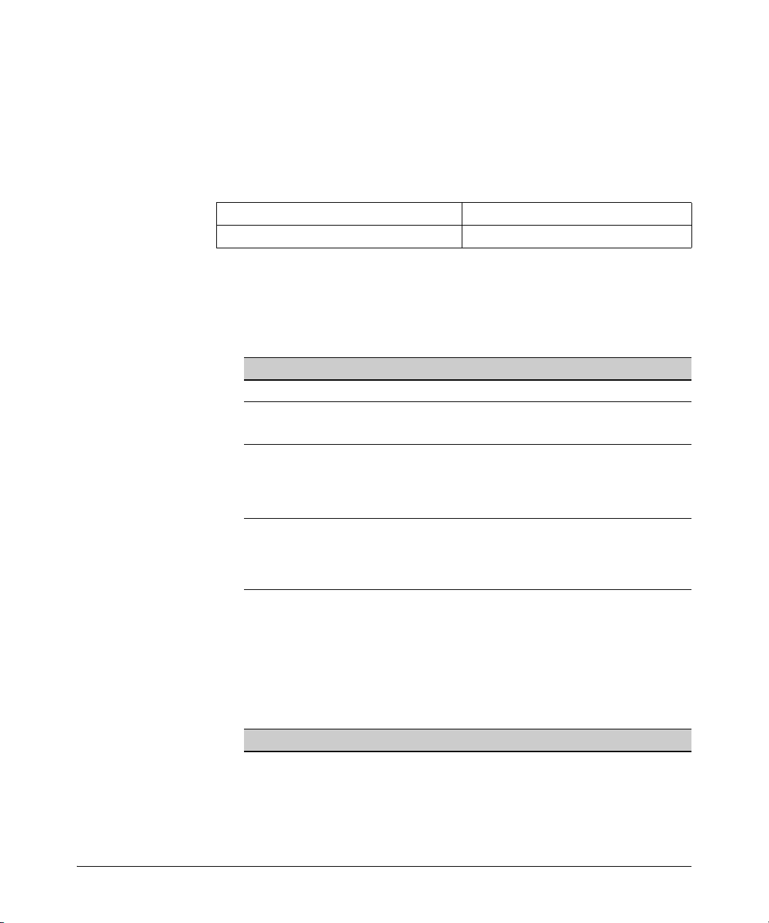
Multicast Application to IPv6 Addressing
■ scope: 0001 - 1110 (bits 13-16)
IPv6 Addressing
For related information, refer to RFC 4291.
Multicast Group Identification
Multicast ID, Flags and Scope (16 bits) Group Identifier (112 bits)
1111 1111 0xxx xxxx :
■ multicast identifier: The first eight high-order bits, set to ff, identify the
address as multicast.
■ multicast flags: Bits 9-12 are multicast flags that provide additional
information about the multicast address, as follows:
Bit ID Options Use
9 0 reserved
10 (R) 0 multicast address without PIM-SM rendezvous point
1 multicast address with PIM-SM rendezvous point
11 (P) 0 multicast address without prefix information from the
originating network
1 multicast address with prefix information from the originating
network
12 (T) 0 multicast address is permanent (well-known, and not
restricted by scope value)
1 multicast address is temporary (and used only within an
identified scope)
x...x : x...x : x...x : x...x : x...x : x...x : x...x
■ multicast scope: Bits 13-16 set boundaries on multicast traffic distribu-
tion, such as the interface defined by the link-local unicast address of an
area, or the network boundaries of an organization. Because IPv6 uses
multicast technology in place of the broadcast technology used in IPv4,
the multicast scope field also controls the boundaries for broadcast-type
traffic sent in multicast packets.
Bit Use
0 reserved
1 interface-local (loopback)
2 link-local (same topology as the corresponding link-local unicast scope)
3 reserved
3-21
Page 66

IPv6 Addressing
Multicast Application to IPv6 Addressing
Bit Use
4 admin-local (smallest administratively configured scope)
5 site-local (single site)
6 unassigned
7 unassigned
8 organization-local (multiple sites within the same organization)
9 unassigned
A unassigned
B unassigned
C unassigned
D unassigned
E global
F reserved
For example, the following prefix indicates multicast traffic with a temporary multicast address and a link-local scope:
ff12 or (binary) 1111 1111 0001 0010
■ group identifier: This field includes the last 112 bits of the multicast
address and contains the actual multicast group identity. (Refer to RFCs
3306, 4291, and 2375.)
3-22
Solicited-Node Multicast Address Format
The solicited-node multicast address the switch generates for a configured
unicast address is composed of a unique, 104-bit multicast prefix
(ff02:0:0:0:0:1:ff) and the last 24 bits of the subject address. For example, if a
VLAN interface is configured with a link-local address of
fe90::215:60ff:fe7a:adc0
then the corresponding solicited-node multicast address is
ff02:0:0:0:0:1:ff7a:adc0
For related information, refer to:
■ RFC 2375: IPv6 Multicast Address Assignments
■ RFC 3306: Unicast-Prefix-based IPv6 Multicast Addresses
■ RFC 3956: Embedding the Rendezvous Point (RP) Address in an IPv6
Multicast Address
■ RFC 3177: IAB/IESG Recommendations on IPv6 Address Allocations to
Sites
Page 67

IPv6 Addressing
Loopback Address
■ RFC 4007: IPv6 Scoped Address Architecture
■ RFC 4291: IP Version 6 Addressing Architecture
■ “Internet Protocol Version 6 Multicast Addresses” (at www.iana.org)
■ RFC 2710: Multicast Listener Discovery (MLD) for IPv6
■ RFC 3810: Multicast Listener Discovery Version 2 (MLDv2) for IPv6
(Updates RFC 2710.)
Loopback Address
The IPv6 loopback address is a link-local unicast address that enables a device
to send traffic to itself for self-testing purposes. The loopback address does
not have a physical interface assignment. If an IPv6 packet destined for the
loopback address is received on a switch interface, it must be dropped. The
IPv6 loopback address is never used as the source IPv6 address for any packet
that is sent out of a device, and the switch drops any traffic it receives with a
loopback address destination. An example use case is:
ProCurve# ping6 ::1
0000:0000:0000:0000:0000:0000:0000:0001 is alive, time = 1 ms
The Unspecified Address
The “unspecified” address is defined as 0.0.0.0.0.0.0.0 (::/128, or just ::). It can
be used, for example, as a temporary source address in multicast traffic sent
by an interface that has not yet acquired its own address. The unspecified
address cannot be statically configured on the switch, or used as a destination
address.
3-23
Page 68

IPv6 Addressing
IPv6 Address Deprecation
IPv6 Address Deprecation
Preferred and Valid Address Lifetimes
Autoconfigured IPv6 global unicast addresses acquire their valid and
preferred lifetime assignments from router advertisements. A valid lifetime is
the time period during which an address is allowed to remain available and
usable on an interface. A preferred lifetime is the length of time an address is
intended for full use on an interface, and must be less than or equal to the
address's valid lifetime.
End of
Preferred
Lifetime
Address
Address “Preferred”
“Deprecated”
Address
Acquired
Valid Lifetime
Address
Removed
Figure 3-1. Valid and Preferred Lifetimes
When the preferred lifetime expires, the address becomes deprecated,
meaning that the address should no longer be used as a source address (except
for existing exchanges that began before the timeout occurred), but can still
be used as a destination. When the timeout arrives for the valid lifetime, the
address becomes unusable.
Notes Preferred and valid lifetimes on a VLAN interface are determined by the router
advertisements received on the interface. These values are not affected by the
lease time assigned to an address by a DHCPv6 server. That is, lease expiration
on a DHCPv6-assigned address terminates use of the address, regardless of
the status of the RA-assigned lifetime, and router-assigned lifetime expiration
of a leased address terminates the switch’s use of the address. (The routerassigned lifetime can be extended by receipt of a new router advertisement.)
Statically configured IPv6 addresses are regarded as permanent addresses,
and do not expire.
3-24
Page 69

IPv6 Address Deprecation
Related Information
■ RFC 2462: “IPv6 Stateless Address Autoconfiguration”
■ RFC 4291: “IP Version 6 Addressing Architecture”
IPv6 Addressing
3-25
Page 70

IPv6 Addressing
IPv6 Address Deprecation
3-26
Page 71

IPv6 Addressing Configuration
Contents
Introduction . . . . . . . . . . . . . . . . . . . . . . . . . . . . . . . . . . . . . . . . . . . . . . . . . . 4-3
General Configuration Steps . . . . . . . . . . . . . . . . . . . . . . . . . . . . . . . . . . . 4-4
Configuring IPv6 Addressing . . . . . . . . . . . . . . . . . . . . . . . . . . . . . . . . . . . . . 4-5
Enabling IPv6 with an Automatically
Configured Link-Local Address . . . . . . . . . . . . . . . . . . . . . . . . . . . . . . . . 4-6
Enabling Autoconfiguration of a Global
Unicast Address and a Default Router Identity on a VLAN . . . . . . . 4-7
Operating Notes . . . . . . . . . . . . . . . . . . . . . . . . . . . . . . . . . . . . . . . . . 4-8
Enabling DHCPv6 . . . . . . . . . . . . . . . . . . . . . . . . . . . . . . . . . . . . . . . . . . . . . 4-9
Operating Notes . . . . . . . . . . . . . . . . . . . . . . . . . . . . . . . . . . . . . . . . 4-10
4
Configuring a Static IPv6 Address on a VLAN . . . . . . . . . . . . . . . . . . 4-11
Statically Configuring a Link-Local Unicast Address . . . . . . . . . . . . 4-12
Statically Configuring A Global Unicast Address . . . . . . . . . . . . . . . . 4-13
Operating Notes . . . . . . . . . . . . . . . . . . . . . . . . . . . . . . . . . . . . . . . . 4-14
Duplicate Address Detection (DAD) for Statically
Configured Addresses . . . . . . . . . . . . . . . . . . . . . . . . . . . . . . . . . . . . . . . 4-15
Disabling IPv6 on a VLAN . . . . . . . . . . . . . . . . . . . . . . . . . . . . . . . . . . . . . 4-15
Neighbor Discovery (ND) . . . . . . . . . . . . . . . . . . . . . . . . . . . . . . . . . . . . . 4-16
Duplicate Address Detection (DAD) . . . . . . . . . . . . . . . . . . . . . . . . . . . 4-17
DAD Operation . . . . . . . . . . . . . . . . . . . . . . . . . . . . . . . . . . . . . . . . . . . . 4-17
Configuring DAD . . . . . . . . . . . . . . . . . . . . . . . . . . . . . . . . . . . . . . . . . . . 4-18
Operating Notes for Neighbor Discovery . . . . . . . . . . . . . . . . . . . 4-19
View the Current IPv6 Addressing Configuration . . . . . . . . . . . . . . 4-21
Router Access and Default Router Selection . . . . . . . . . . . . . . . . . . . 4-28
Router Advertisements . . . . . . . . . . . . . . . . . . . . . . . . . . . . . . . . . . . . . . 4-28
Router Solicitations . . . . . . . . . . . . . . . . . . . . . . . . . . . . . . . . . . . . . . . . 4-28
4-1
Page 72

IPv6 Addressing Configuration
Contents
View IPv6 Gateway, Route, and Router Neighbors . . . . . . . . . . . . . 4-30
Address Lifetimes . . . . . . . . . . . . . . . . . . . . . . . . . . . . . . . . . . . . . . . . . . . . 4-33
Default IPv6 Router . . . . . . . . . . . . . . . . . . . . . . . . . . . . . . . . . . . . . . . . . 4-29
Router Redirection . . . . . . . . . . . . . . . . . . . . . . . . . . . . . . . . . . . . . . . . . 4-29
Viewing Gateway and IPv6 Route Information . . . . . . . . . . . . . . . . . . 4-30
Viewing IPv6 Router Information . . . . . . . . . . . . . . . . . . . . . . . . . . . . . 4-31
Preferred Lifetime . . . . . . . . . . . . . . . . . . . . . . . . . . . . . . . . . . . . . . . . . . 4-33
Valid Lifetime . . . . . . . . . . . . . . . . . . . . . . . . . . . . . . . . . . . . . . . . . . . . . . 4-33
Sources of IPv6 Address Lifetimes . . . . . . . . . . . . . . . . . . . . . . . . . . . . 4-33
4-2
Page 73

IPv6 Addressing Configuration
Introduction
Introduction
Feature Default CLI
Enable IPv6 with a Link-Local
Address
Configure Global Unicast disabled 4-7
Autoconfig
Configure DHCPv6 Addressing disabled 4-9
Configure a Static Link-Local None 4-12
Address
Configure a Static Global Unicast None 4-13
Address
Change DAD Attempts 3 4-17
View Current IPv6 Addressing n/a 4-21
In the default configuration, IPv6 operation is disabled on the switch. This
section describes the general steps and individual commands for enabling
IPv6 operation.
disabled 4-6
This chapter provides the following:
■ general steps for IPv6 configuration
■ IPv6 command syntax descriptions, including show commands
Most IPv6 configuration commands are applied per-VLAN. The exceptions are
ICMP, ND (neighbor discovery), and the (optional) authorized-managers
feature, which are configured at the global configuration level. (ICMP and ND
for IPv6 are enabled with default values when IPv6 is first enabled, and can
either be left in their default settings or reconfigured, as needed.) For more
information on ICMP, refer to “ICMP Rate-Limiting” on page 9-2. For more on
ND, refer to “Neighbor Discovery (ND) in IPv6” on page 2-9.
For a quick reference to all IPv6 commands available on the switch, refer to
the “IPv6 Command Index” on page xv at the front of this guide.
Note Beginning with software release K.13.01, the switch is capable of operating in
dual-stack mode, where IPv4 and IPv6 run concurrently on a given VLAN.
4-3
Page 74

IPv6 Addressing Configuration
General Configuration Steps
General Configuration Steps
The IPv6 configuration on switches running software release K.13.01 or
greater includes global and per-VLAN settings. This section provides an overview of the general configuration steps for enabling IPv6 on a given VLAN and
can be enabled by any one of several commands. The following steps provide
a suggested progression for getting started.
Note The ICMP and Neighbor Discovery (ND) parameters are set to default values
at the global configuration level are satisfactory for many applications and
generally do not need adjustment when you are first configuring IPv6 on the
switch.
In the default configuration, IPv6 is disabled on all VLANs.
1. If IPv6 DHCP service is available, enable IPv6 DHCP on the VLAN. If IPv6
is not already enabled on the VLAN, enabling DHCPv6 also enables IPv6
and automatically configures a link-local address using the EUI-64 format.
Note If IPv6 is not already enabled on the VLAN, enabling DHCPv6 causes the
switch to automatically generate a link-local address. DHCPv6 does not assign
a link-local address.
A DHCPv6 server can provide other services, such as the addresses of
time servers. For this reason you may want to enable DHCP even if you
are using another method to configure IPv6 addressing on the VLAN.
2. If IPv6 DHCP service is not enabled on the VLAN, then do either of the
following:
• Enable IPv6 on the VLAN. This automatically configures a link-local
address with an EUI- 64 interface identifier.
• Statically configure a unicast IPv6 address on the VLAN. This enables
IPv6 on the VLAN and, if you configure anything other than a linklocal address, the link-local address will be automatically configured
as well, with an EUI-64 interface identifier.
3. If an IPv6 router is connected on the VLAN, then enable IPv6 address
autoconfiguration to automatically configure global unicast addresses
with prefixes included in advertisements received from the router. The
device identifier used in addresses configured by this method will be the
same as the device identifier in the current link-local address.
4-4
Page 75

IPv6 Addressing Configuration
Configuring IPv6 Addressing
4. If needed, statically configure IPv6 unicast addressing on the VLAN
interface as needed. This can include any of the following:
• statically replacing the automatically generated link-local address
• statically adding global unicast and unique local unicast addresses
Configuring IPv6 Addressing
In the default configuration on a VLAN, any one of the following commands
enables IPv6 and creates a link-local address. Thus, while any one of these
methods is configured on a VLAN, IPv6 remains enabled and a link-local
address is present:
ipv6 enable (page 4-6)
ipv6 address autoconfig (page 4-7)
ipv6 address dhcp full [rapid-commit] (page 4-9)
ipv6 address fe80:0:0:0:< device-identifier > link-local (page 4-12)
ipv6 address < prefix:device-identifier > (page 4-13)
Note Addresses created by any of these methods remain tentative until verified as
unique by Duplicate Address Detection. (Refer to “Duplicate Address Detection (DAD)” on page 4-17.)
4-5
Page 76

IPv6 Addressing Configuration
Enabling IPv6 with an Automatically Configured Link-Local Address
Enabling IPv6 with an Automatically
Configured Link-Local Address
This command enables automatic configuration of a link-local address .
Syntax: [no] ipv6 enable
If IPv6 has not already been enabled on a VLAN by another
IPv6 command option described in this chapter, this command
enables IPv6 on the VLAN and automatically configures the
VLAN's link-local unicast address with a 64-bit EUI-64 interface identifier generated from the VLAN MAC address. (Refer
to “Extended Unique Identifier (EUI)” on page 3-14.).
Note: Only one link-local IPv6 address is allowed on the
VLAN interface. Subsequent static or DHCP configuration
of another link-local address overwrites the existing linklocal address.
A link-local address always uses the prefix fe80:0:0:0.
With IPv6 enabled, the VLAN uses received router advertisements to designate the default IPv6 router. (Refer to “Default
IPv6 Router” on page 4-29.)
4-6
After verification of uniqueness by DAD, a link-local IPv6
address assigned automatically is set to the preferred status,
with a “permanent” lifetime. (Refer to “IPv6 Address Deprecation” on page 3-24.)
Default: Disabled
The no form of the command disables IPv6 on the VLAN if no
other IPv6-enabling command is configured on the VLAN.
(Refer to “Disabling IPv6 on a VLAN” on page 4-15.)
To view the current IPv6 Enable setting and any statically configured IPv6
addresses per-VLAN, use show run.
To view all currently configured IPv6 unicast addresses, use the following:
■ show ipv6 (Lists IPv6 addresses for all VLANs configured on the switch.)
■ show ipv6 vlan < vid > (Lists IPv6 addresses configured on the VLAN.)
For more information, refer to “View the Current IPv6 Addressing Configuration” on page 4-21.
Page 77

Enabling Autoconfiguration of a Global Unicast Address and a Default Router Identity on a VLAN
IPv6 Addressing Configuration
Enabling Autoconfiguration of a Global
Unicast Address and a Default Router
Identity on a VLAN
Enabling autoconfig or rebooting the switch with autoconfig enabled on a
VLAN causes the switch to configure IPv6 addressing on the VLAN using
router advertisements and an EUI-64 interface identifier (page 3-14).
Syntax: [no] ipv6 address autoconfig
Implements unicast address autoconfiguration as follows:
■ If IPv6 is not already enabled on the VLAN, this command
enables IPv6 and generates a link-local (EUI- 64) address.
■ Generates router solicitations (RS) on the VLAN.
■ If a router advertisement (RA) is received on the VLAN,
the switch uses the route prefix in the RA to configure a
global unicast address. The device identifier for this
address will be the same as the device identifier used in
the current link-local address at the time the RA is
received. (This can be either a statically configured or the
(automatic) EUI-64 device identifier, depending on how
the link-local address was configured.) For information
on EUI- 64, refer to “Extended Unique Identifier (EUI)”
on page 3-14.) If an RA is not received on the VLAN after
autoconfig is enabled, a link-local address will be present,
but no global unicast addresses will be autoconfigured.
Notes: If a link-local address is already configured on the
VLAN, a later, autoconfigured global unicast address uses
the same device identifier as the link-local address.
Autoconfigured and DHCPv6-assigned global unicast
addresses with the same prefix are mutually exclusive on
a VLAN. On a given switch, if both options are configured
on the same VLAN, then only the first to acquire a global
unicast address will be used.
— Continued on the next page. —
4-7
Page 78

IPv6 Addressing Configuration
Enabling Autoconfiguration of a Global Unicast Address and a Default Router Identity on a VLAN
— Continued from the previous page. —
After verification of uniqueness by DAD, an IPv6 address
assigned to a VLAN by autoconfiguration is set to the preferred
and valid lifetimes specified by the RA used to generate the
address, and is configured as a preferred address. (Refer to
“IPv6 Address Deprecation” on page 3-24.)
Default: Disabled.
The no form of the command produces different results,
depending on how IPv6 is configured on the VLAN:
If IPv6 was enabled only by the autoconfig command, then
deleting this command disables IPv6 on the VLAN. (Refer to
“Disabling IPv6 on a VLAN” on page 4-15.)
To view the current IPv6 autoconfiguration settings per-VLAN, use show run.
To view all currently configured IPv6 unicast addresses, use the following:
■ show ipv6 (Lists IPv6 addresses for all VLANs configured on the switch.)
■ show ipv6 vlan < vid > (Lists IPv6 addresses configured on the VLAN.)
4-8
For more information, refer to “View the Current IPv6 Addressing Configuration” on page 4-21.
Operating Notes
With IPv6 enabled, the VLAN uses received router advertisements to designate
the default IPv6 router. (Refer to “Router Access and Default Router Selection”
on page 4-28.)
Page 79

IPv6 Addressing Configuration
Enabling DHCPv6
Enabling DHCPv6
Enabling the DHCPv6 option on a VLAN allows the switch to obtain a global
unicast address and an NTP (network time protocol) server assignment for a
Timep server. (If a DHCPv6 server is not needed to provide a global unicast
address to a switch interface, the server can still be configured to provide the
NTP server assignment. This is sometimes referred to as “stateless DHCPv6”.)
Syntax: [no] ipv6 address dhcp full [rapid-commit]
This option configures DHCPv6 on a VLAN, which initiates
transmission of DHCPv6 requests for service. If IPv6 is not
already enabled on the VLAN by the ipv6 enable command, this
option also enables IPv6 and causes the switch to autoconfigure a link-local unicast address with an EUI-64 interface
identifier.
Notes: A DHCPv6 server does not assign link-local
addresses, and enabling DHCPv6 on a VLAN does not
affect a pre-existing link-local address configured on the
VLAN.
A DHCPv6-assigned address can be configured on a VLAN
when the following is true:
• The assigned address is not on the same subnet as a
previously configured autoconfig address.
• The maximum IPv6 address limit on the VLAN or the
switch has not been reached.
If a DHCPv6 server responds with an IPv6 address assignment, this address is assigned to the VLAN. (The DHCPv6assigned address will be dropped if it has the same subnet as
another address already assigned to the VLAN by an earlier
autoconfig command.)
— Continued on the next page. —
4-9
Page 80

IPv6 Addressing Configuration
Enabling DHCPv6
— Continued from the previous page. —
After verification of uniqueness by DAD, an IPv6 address
assigned to the VLAN by an DHCPv6 server is set to the
preferred and valid lifetimes specified in a router advertisement received on the VLAN for the prefix used in the assigned
address, and is configured as a preferred address. (Refer to
the section titled “Address Lifetimes” on page 4-33.)
[rapid-commit]: Expedites DHCP configuration by using a twomessage exchange with the server (solicit-reply) instead of the
default four-message exchange (solicit-advertise- requestreply).
Default: Disabled
The no form of the command removes the DHCPv6 option from
the configuration and, if no other IPv6-enabling command is
configured on the VLAN, disables IPv6 on the VLAN. (Refer to
“Disabling IPv6 on a VLAN” on page 4-15.)
To view the current IPv6 DHCPv6 settings per-VLAN, use show run.
To view all currently configured IPv6 unicast addresses, use the following:
■ show ipv6 (Lists IPv6 addresses for all VLANs configured on the switch.)
■ show ipv6 vlan < vid > (Lists IPv6 addresses configured on the VLAN.)
For more information, refer to “View the Current IPv6 Addressing Configuration” on page 4-21.
Operating Notes
■ If multiple DHCPv6 servers are available, the switch selects a server based
on the preference value sent in DHCPv6 messages from the servers.
■ The switch supports both DHCPv4 and DHCPv6 client operation on the
same VLAN.
■ DHCPv6 authentication and stateless DHCPv6 are not supported in soft-
ware releases K.13.01 or greater.
■ With IPv6 enabled, the switch determines the default IPv6 router for the
VLAN from the router advertisements it receives. (Refer to “Default IPv6
Router” on page 4-29.)
4-10
Page 81

Configuring a Static IPv6 Address on a VLAN
■ DHCPv6 and statically configured global unicast addresses are mutually
IPv6 Addressing Configuration
exclusive on a given VLAN. That is, configuring DHCPv6 on a VLAN erases
any static global unicast addresses previously configured on that VLAN,
and the reverse. (A statically configured link-local address will not be
affected by configuring DHCPv6 on the VLAN.)
■ For the same subnet on the switch, a DHCPv6 global unicast address
assignment takes precedence over an autoconfigured address assignment, regardless of which address type was the first to be configured. If
DHCPv6 is subsequently removed from the configuration, then an autoconfigured address assignment will replace it after the next router advertisement is received on the VLAN. DHCPv6 and autoconfigured addresses
co-exist on the same VLAN if they belong to different subnets.
For related information refer to:
■ RFC 3315: “Dynamic Host Configuration Protocol for IPv6 (DHCPv6)”
■ RFC 3633: “IPv6 Prefix Options for Dynamic Host Configuration Protocol
(DHCP) version 6”
■ RFC 3736: “Stateless Dynamic Host Configuration Protocol (DHCP)
Service for IPv6”
Configuring a Static IPv6 Address on a
VLAN
This option enables configuring of unique, static unicast IPv6 addresses for
global and link-local applications, including:
■ link-local unicast (including EUI and non-EUI device identifiers)
■ global unicast (and unique local unicast)
4-11
Page 82

IPv6 Addressing Configuration
Configuring a Static IPv6 Address on a VLAN
Statically Configuring a Link-Local Unicast Address
Syntax: [no] ipv6 address fe80::< device-identifier > link-local
■ If IPv6 is not already enabled on the VLAN, this command
enables IPv6 and configures a static link-local address.
■ If IPv6 is already enabled on the VLAN, then this command
overwrites the current, link- local address with the specified static address. (One link-local address is allowed per
VLAN interface.)
< device-identifier >: The low-order 64 bits, in 16-bit blocks,
comprise this value in a link-local address:
xxxx xxxx : xxxx xxxx : xxxx xxxx : xxxx xxxx
Where a static link-local address is already configured, a new,
autoconfigured global unicast addresses assignment uses the
same device identifier as the link-local address.
Notes: An IPv4 loopback address must be configured on the
switch before you use the ipv6 address command to statically
configure an address. Refer to “Operating Notes” on page 4-
14.
An existing link-local address is replaced, and is not
deprecated, when a static replacement is configured.
The prefix for a statically configured link-local address is
always 64 bits, with all blocks after fe80 set to zero. That is:
fe80:0:0:0.
4-12
After verification of uniqueness by DAD, a statically configured link-local address status is set to preferred, with a perma-
nent lifetime. (Refer to “IPv6 Address Deprecation” on page 3-
24.)
For link-local addressing, the no form of the static IPv6 address
command produces different results, depending on how IPv6
is configured on the VLAN:
Page 83

Configuring a Static IPv6 Address on a VLAN
■ If IPv6 was enabled only by a statically configured link-
IPv6 Addressing Configuration
local address, then deleting the link-local address disables
IPv6 on the VLAN.
■ If other IPv6-enabling commands have been configured on
the VLAN, then deleting the statically configured link-local
address causes the switch to replace it with the default
(EUI-64) link-local address for the VLAN, and IPv6
remains enabled. (For more on the EUI-64 address format,
refer to “Extended Unique Identifier (EUI)” on page 3-14.)
Refer also to “Disabling IPv6 on a VLAN” on page 4-15.
Statically Configuring A Global Unicast Address
Syntax:.
[no] ipv6 address < network-prefix><device-id >/< prefix-length >
[no] ipv6 address < network-prefix>::/< prefix-length > eui-64
If IPv6 is not already enabled on a VLAN, either of these
command options do the following:
■ enable IPv6 on the VLAN
■ configure a link-local address using the EUI-64 format
■ statically configure a global unicast address
Note: An IPv4 loopback address must be configured on the
switch before you use the ipv6 address command to statically
configure an address. Refer to “Operating Notes” on page 4-
14.
If IPv6 is already enabled on the VLAN, then the above
commands statically configure a global unicast address, but
have no effect on the current link-local address.
< network-prefix >: This includes the global routing prefix and
the subnet ID for the address. For more on this topic, refer to
“Prefixes in Routable IPv6 Addresses” on page 3-18.
< device-id >: Enters a user-defined device identity.
4-13
Page 84

IPv6 Addressing Configuration
Configuring a Static IPv6 Address on a VLAN
To view the currently configured static IPv6 addresses per-VLAN, use show run.
To view all currently configured IPv6 unicast addresses, use the following:
■ show ipv6 (Lists IPv6 addresses for all VLANs configured on the switch.)
■ show ipv6 vlan < vid > (Lists IPv6 addresses configured on VLAN < vid >.)
< prefix-length >: Specifies the number of bits in the network
prefix. If you are using the eui-64 option, this value must be 64.
eui-64: Specifies using the Extended Unique Identifier format
to create a device identifier based on the VLAN MAC address.
Refer to “Extended Unique Identifier (EUI)” on page 3-14.
After verification of uniqueness by DAD, the lifetime of a
statically configured IPv6 address assigned to a VLAN is set
to permanent, and is configured as a preferred address. (Refer
to “IPv6 Address Deprecation” on page 3-24.)
The no form of the command erases the specified address and,
if no other IPv6-enabling command is configured on the VLAN,
disables IPv6 on the VLAN. (Refer to “Disabling IPv6 on a
VLAN” on page 4-15.)
4-14
For more information, refer to “View the Current IPv6 Addressing Configuration” on page 4-21.
Operating Notes
■ With IPv6 enabled, the switch determines the default IPv6 router for the
VLAN from the router advertisements it receives. (Refer to “Router Access
and Default Router Selection” on page 4-28.)
■ If DHCPv6 is configured on a VLAN, then configuring a static global
unicast address on the VLAN removes DHCPv6 from the VLAN's configuration and deletes the DHCPv6-assigned global unicast address.
■ Note that for a statically configured global unicast address to be routable,
a gateway router must be transmitting router advertisements on the
VLAN.
■ If an autoconfigured global unicast address already exists for the same
subnet as a new, statically configured global unicast address, the statically
configured address is denied. In the reverse case, you can add an autoconfig command to the VLAN configuration, but it will not be implemented unless the static address is removed from the configuration.
Page 85

IPv6 Addressing Configuration
Disabling IPv6 on a VLAN
Duplicate Address Detection (DAD) for Statically Configured Addresses
Statically configured IPv6 addresses are designated as permanent. If DAD
determines that a statically configured address duplicates a previously configured and reachable address on another device belonging to the VLAN, then
the more recent, duplicate address is designated as duplicate. For more on this
topic, refer to:
■ “Duplicate Address Detection (DAD)” on page 4-17.
■ “View the Current IPv6 Addressing Configuration” on page 4-21
Disabling IPv6 on a VLAN
While one IPv6-enabling command is configured on a VLAN, IPv6 remains
enabled on that VLAN. In this case, removing the only IPv6-enabling command
from the configuration disables IPv6 operation on the VLAN. That is, to disable
IPv6 on a VLAN, all of the following commands must be removed from the
VLAN's configuration:
ipv6 enable
ipv6 address dhcp full [rapid-commit]
ipv6 address autoconfig
ipv6 address fe80::< device-identifier > link-local
ipv6 address < prefix > : < device-identifier >
If any of the above remain enabled, then IPv6 remains enabled on the VLAN
and, at a minimum, a link-local unicast address will be present.
4-15
Page 86

IPv6 Addressing Configuration
Neighbor Discovery (ND)
Neighbor Discovery (ND)
Neighbor Discovery (ND) is the IPv6 equivalent of the IPv4 ARP for layer 2
address resolution, and uses IPv6 ICMP messages to do the following:
■ Determine the link-layer address of neighbors on the same VLAN inter-
■ Verify that a neighbor is reachable.
■ Track neighbor (local) routers.
Neighbor Discovery enables functions such as the following:
■ router and neighbor solicitation and discovery
■ detecting address changes for devices on a VLAN
■ identifying a replacement for a router or router path that has become
■ duplicate address detection (DAD)
■ router advertisement processing
■ neighbor reachability
■ autoconfiguration of unicast addresses
■ resolution of destination addresses
■ changes to link-layer addresses
face.
unavailable
4-16
An instance of Neighbor Discovery is triggered on a device when a new
(tentative) or changed IPv6 address is detected. (This includes stateless,
stateful, and static address configuration.) ND operates in a per-VLAN scope;
that is, within the VLAN on which the the device running the ND instance is a
member. Neighbor discovery actually occurs when there is communication
between devices on a VLAN. That is, a device needing to determine the linklayer address of another device on the VLAN initiates a (multicast) neighbor
solicitation message (containing a solicited-node multicast address that corresponds to the IPv6 address of the destination device) on the VLAN. When the
destination device receives the neighbor solicitation, it responds with a
neighbor advertisement message identifying its link-layer address. When the
initiating device receives this advertisement, the two devices are ready to
exchange traffic on the VLAN interface. Also, when an IPv6 interface becomes
operational, it transmits a router solicitation on the interface and listens for a
router advertisement.
Page 87

IPv6 Addressing Configuration
Duplicate Address Detection (DAD)
Note: Neighbor and router solicitations must originate on the same VLAN as the
receiving device. To support this operation, IPv6 is designed to discard any
incoming neighbor or router solicitation that does not have a value of 255 in
the IP Hop Limit field. For a complete list of requirements, refer to RFC 246.
When a pair of IPv6 devices in a VLAN exchange communication, they enter
each other's IPv6 and corresponding MAC addresses in their respective
neighbor caches. These entries are maintained for a period of time after
communication ceases, and then dropped.
To view or clear the content of the neighbor cache, refer to “Viewing and
Clearing the IPv6 Neighbors Cache” on page 5-2.
For related information, refer to:
■ RFC 2461: “Neighbor Discovery for IP Version 6 (IPv6)”
Duplicate Address Detection (DAD)
Duplicate Address Detection verifies that a configured unicast IPv6 address
is unique before it is assigned to a VLAN interface on the switch. DAD is
enabled in the default IPv6 configuration, and can be reconfigured, disabled,
or re-enabled at the global config command level. DAD can be useful in helping
to troubleshoot erroneous replies to DAD requests, or where the neighbor
cache contains a large number of invalid entries due to an unauthorized station
sending false replies to the switch's neighbor discovery queries. If DAD
verifies that a unicast IPv6 address is a duplicate, the address is not used. If
the link-local address of the VLAN interface is found to be a duplicate of an
address for another device on the interface, then the interface stops
processing IPv6 traffic.
DAD Operation
On a given VLAN interface, when a new unicast address is configured, the
switch runs DAD for this address by sending a neighbor solicitation to the AllNodes multicast address (ff02::1). This operation discovers other devices on
the VLAN and verifies whether the proposed unicast address assignment is
unique on the VLAN. (During this time, the address being checked for uniqueness is held in a tentative state, and cannot be used to receive traffic other
than neighbor solicitations and neighbor advertisements.) A device that
receives the neighbor solicitation responds with a Neighbor Advertisement
4-17
Page 88

IPv6 Addressing Configuration
Duplicate Address Detection (DAD)
that includes its link-local address. If the newly configured address is from a
static or DHCPv6 source and is found to be a duplicate, it is labelled as
duplicate in the “Address Status” field of the show ipv6 command, and is not
used. If an autoconfigured address is found to be a duplicate, it is dropped and
the following message appears in the Event Log:
DAD does not perform periodic checks of existing addresses. However, when
a VLAN comes up with IPv6 unicast addresses configured (as can occur during
a reboot) the switch runs DAD for each address on the interface by sending
neighbor solicitations to the All-Nodes multicast address as described above.
If an address is configured while DAD is disabled, the address is assumed to
be unique and is assigned to the interface. If you want to verify the uniqueness
of an address configured while DAD was disabled, re-enable DAD and then
either delete and reconfigure the address, or reboot the switch.
Configuring DAD
W < date > < time > 00019 ip: ip address < IPv6-address >
removed from vlan id < vid >
Syntax: ipv6 nd dad-attempts < 0 - 600 >
This command is executed at the global config level, and
configures the number of neighbor solicitations to send when
performing duplicate address detection for a unicast address
configured on a VLAN interface.
< 0 - 600 >: The number of consecutive neighbor solicitation
messages sent for DAD inquiries on an interface. Setting this
value to 0 disables DAD on the interface. Disabling DAD
bypasses checks for uniqueness on newly configured
addresses. If a reboot is performed while DAD is disabled, the
duplicate address check is not performed on any IPv6
addresses configured on the switch.
Default: 3 (enabled); Range: 0 - 600 (0 = disabled)
The no form of the command restores the default setting (3).
4-18
Page 89

Syntax: ipv6 nd ns-interval < milliseconds >
Used on VLAN interfaces to reconfigure the neighbor discovery
time in milliseconds between DAD neighbor solicitations sent
for an unresolved destination, or between duplicate address
detection neighbor solicitation requests. Increasing this
setting is indicated where neighbor solicitation retries or
failures are occurring, or in a “slow” (WAN) network .
To view the current setting, use show ipv6 nd.
Range: 1000 - 3600000 ms; Default: 1000 ms.
Syntax: ipv6 nd reachable-time < milliseconds >
Used on VLAN interfaces to configure the length of time in
milliseconds a neighbor will be considered reachable after the
Neighbor Unreachability Detection algorithm has confirmed
it to be reachable. When the switch operates in host mode, this
setting can be overridden by a reachable time received in a
router advertisement.
IPv6 Addressing Configuration
Duplicate Address Detection (DAD)
To view the current setting, use show ipv6 nd.
Range: 1000 - 2147483647 ms; Default: 30000 ms.
Operating Notes for Neighbor Discovery
■ A verified link-local unicast address must exist on a VLAN interface before
the switch can run DAD on other addresses associated with the interface.
■ If a previously configured unicast address is changed, a neighbor adver-
tisement (an all-nodes multicast message--ff02::1) is sent to notify other
devices on the VLAN and to perform duplicate address detection.
■ IPv6 addresses on a VLAN interface are assigned to multicast address
groups identified with well- known prefixes. For more on this topic, refer
to “Multicast Application to IPv6 Addressing” on page 3-19.
■ DAD is performed on all stateful, stateless, and statically configured
unicast addresses.
■ Neighbor solicitations for DAD do not cause the neighbor cache of
neighboring switches to be updated.
4-19
Page 90

IPv6 Addressing Configuration
Duplicate Address Detection (DAD)
■ If a previously configured unicast address is changed, a neighbor adver-
tisement is sent on the VLAN to notify other devices, and also for duplicate
address detection.
■ If DAD is disabled when an address is configured, the address is assumed
to be unique and is assigned to the interface.
4-20
Page 91

View the Current IPv6 Addressing Configuration
IPv6 Addressing Configuration
View the Current IPv6 Addressing
Configuration
Use these commands to view the current status of the IPv6 configuration on
the switch.
Syntax: show ipv6
Lists the current, global IPv6 settings and per-VLAN IPv6
addressing on the switch.
IPv6 Routing: For software releases K.13.01 through K.14.01,
this setting is always Disabled. This is a global setting, and is
not configured per-VLAN. (Refer to “Router Access and Default
Router Selection” on page 4-28.)
Default Gateway: Lists the IPv4 default gateway, if any, configured on the switch. This is a globally configured router
gateway address, and is not configured per-VLAN.
ND DAD: Indicates whether DAD is enabled (the default) or
disabled. Using ipv6 nd dad-attempts 0 disables neighbor
discovery. (Refer to “Duplicate Address Detection (DAD)” on
page 4-17.)
DAD Attempts: Indicates the number of neighbor solicitations
the switch transmits per-address for duplicate (IPv6) address
detection. Implemented when a new address is configured or
when an interface with configured addresses comes up (such
as after a reboot). The default setting is 3, and the range is 0
- 600. A setting of “0” disables duplicate address detection.
(Refer to “Duplicate Address Detection (DAD)” on page 4-17.)
VLAN Name: Lists the name of a VLAN statically configured on
the switch.
IPv6 Status: For the indicated VLAN, indicates whether IPv6 is
disabled (the default) or enabled. (Refer to “Configuring IPv6
Addressing” on page 4-5.)
4-21
Page 92

IPv6 Addressing Configuration
View the Current IPv6 Addressing Configuration
Address Origin:
■ Autoconfig: The address was configured using stateless
■ DHCP: The address was assigned by a DHCPv6 server. Note
■ Manual: The address was statically configured on the
■ IPv6 Address/Prefix Length: Lists each IPv6 address and
Address Status:
■ Tentative: DAD has not yet confirmed the address as
■ Preferred: The address has been confirmed as unique by
■ Deprecated: The preferred lifetime for the address has been
■ Duplicate: Indicates a statically configured IPv6 address
address autoconfiguration (SLAAC). In this case, the
device identifier for global unicast addresses copied from
the current link-local unicast address.
that addresses having a DHCP origin are listed with a 128bit prefix length.
VLAN.
prefix length configured on the indicated VLAN.
unique, and is not usable for sending and receiving traffic.
DAD, and usable for sending and receiving traffic. The
Expiry time shown for this address by the show ipv6 vlan
< vid > command output is the preferred lifetime assigned
to the address. (Refer to "Address Lifetimes" on page xxx.)
exceeded, but there is time remaining in the valid lifetime.
that is a duplicate of another IPv6 address that already
exists on another device belonging to the same VLAN
interface. A duplicate address is not used.
4-22
Page 93

For example, figure 4-1 shows the output on a switch having IPv6 enabled on
one VLAN.
ProCurve# show ipv6
Internet (IPv6) Service
IPv6 Routing : Disabled
Default Gateway : fe80::213:c4ff:fedd:14b0
ND DAD : Enabled
DAD Attempts : 3
Vlan Name : DEFAULT_VLAN
IPv6 Status : Disabled
Vlan Name : VLAN10
IPv6 Status : Enabled
View the Current IPv6 Addressing Configuration
IPv6 Addressing Configuration
Address | Address
Origin | IPv6 Address/Prefix Length Status
---------- + ------------------------------------------- ---------- dhcp | 2001:db8:a03:e102::1:101/64 preferred
manual | fe80::1:101/64 preferred
Figure 4-1. Example of Show IPv6 Command Output
4-23
Page 94

IPv6 Addressing Configuration
View the Current IPv6 Addressing Configuration
Syntax: show ipv6 nd
Displays the current IPv6 neighbor discovery settings on the
configured VLAN interfaces.
For example, figure 4-24 shows the output on a switch having IPv6 enabled
on VLANs 1 and 20.
ProCurve# show ipv6 nd
IPV6 Neighbor Discovery Configuration
Current Hop Limit : 0
VLAN Name RCHtime NSint
------------ -------- ------- DEFAULT_VLAN 30000 1000
VLAN20 30000 1000
Figure 4-2. Example of Show IPv6 nd Output with Default settings
(msecs) (msecs)
4-24
Syntax: show ipv6 vlan < vid >
Displays IP and IPv6 global configuration settings, the IPv6
status for the specified VLAN, the IPv6 addresses (with prefix
lengths) configured on the specified VLAN, and the expiration
data (Expiry) for each address.:
■ IPv6 Routing: For software releases K.13.01 through
K.14.01, this setting is always Disabled. (Refer to “Router
Access and Default Router Selection” on page 4-28.).
■ Default Gateway: Lists the IPv4 default gateway, if any,
configured on the switch. This is a globally configured
router gateway address, and is not configured per-VLAN.
■ ND DAD: Shows whether Neighbor Discovery (ND) is
enabled. The default setting is Enabled. Using ipv6 nd dad-
attempts 0 disables neighbor discovery.
Page 95

View the Current IPv6 Addressing Configuration
■ DAD Attempts: Indicates the number of neighbor solicita-
IPv6 Addressing Configuration
tions the switch transmits per-address for duplicate
(IPv6) address detection. Implemented when a new
address is configured or when an interface with configured addresses comes up (such as after a reboot). The
default setting is 3, and the range is 0 - 600. A setting of
“0” disables duplicate address detection. (Refer to “Duplicate Address Detection (DAD)” on page 4-17.)
■ VLAN Name: Lists the name of a VLAN statically configured
on the switch.
■ IPv6 Status: For the indicated VLAN, indicates whether
IPv6 is disabled (the default) or enabled. (Refer to “Configuring IPv6 Addressing” on page 4-5.)
■ IPv6 Address/Prefix Length: Lists each IPv6 address and
prefix length configured on the indicated VLAN.
■ Expiry: Lists the lifetime status of each IPv6 address listed
for a VLAN:
• Permanent: The address will not time out and need
renewal or replacement.
• date/time: The date and time that the address expires.
Expiration date and time is specified in the router
advertisement used to create the prefix for automatically configured, global unicast addresses. The Address
Status field in the show ipv6 command output indicates
whether this date/time is for the “preferred” or “valid”
lifetime assigned to the corresponding address. (Refer
to “Preferred and Valid Address Lifetimes” on page 3-
24.)
4-25
Page 96

IPv6 Addressing Configuration
View the Current IPv6 Addressing Configuration
ProCurve# show ipv6 vlan 10
Internet (IPv6) Service
IPv6 Routing : Disabled
Default Gateway : fe80::213:c4ff:fedd:14b0%vlan10
ND DAD : Enabled
DAD Attempts : 3
Vlan Name : VLAN10
IPv6 Status : Enabled
IPv6 Address/Prefixlength Expiry
------------------------------------------- ------------------------ 2001:db8:a03:e102::1:101/64 Fri May 19 11:51:15 2009
fe80::1:101/64 permanent
Figure 4-3. Example of Show IPv6 VLAN < vid > Output
4-26
Syntax: show run
In addition to the other elements of the current configuration,
this command lists the statically configured, global unicast
IPv6 addressing, and the current IPv6 configuration perVLAN. The listing may include one or more of the following,
depending on what other IPv6 options are configured on the
VLAN. Any stateless address autoconfiguration (SLAAC)
commands in the configuration are also listed in the output,
but the actual addresses resulting from these commands are
not included in the output.
■ ipv6 enable
■ ipv6 address fe80::< device-id > link-local
■ ipv6 address < prefix >:< device-id >/< prefix-length >
■ ipv6 address autoconfig
■ ipv6 address dhcp full [rapid-commit]
■ ipv6 < global-unicast-address >/< prefix >
Page 97

View the Current IPv6 Addressing Configuration
IPv6 Addressing Configuration
ProCurve(config)# show run
Running configuration:
.
.
.
vlan 10
name "VLAN10"
untagged A1-A12
ipv6 address fe80::1:101 link-local
Statically configured IPv6 addresses
appear in the show run output.
ipv6 address dhcp full rapid-commit
.
.
.
Commands for automatic IPv6 address
configuration appear in the show run
output, but the addresses resulting from
these commands do not appear in the
output.
Figure 4-4. Example of Show Run Output Listing the Current IPv6 Addressing Commands
4-27
Page 98

IPv6 Addressing Configuration
Router Access and Default Router Selection
Router Access and Default Router
Selection
Routing traffic between destinations on different VLANs configured on the
switch or to a destination on an off-switch VLAN is done by placing the switch
on the same VLAN interface or subnet as an IPv6-capable router configured
to route traffic to other IPv6 interfaces or to tunnel IPv6 traffic across an IPv4
network.
Router Advertisements
An IPv6 router periodically transmits router advertisements (RAs) on the
VLANs to which it belongs to notify other devices of its presence. The switch
uses these advertisements for purposes such as:
■ learning the MAC and link-local addresses of IPv6 routers on the VLAN
(For devices other than routers, the switch must use neighbor discovery
to learn these addresses.)
■ building a list of default (reachable) routers, along with router lifetime
and prefix lifetime data
■ learning the prefixes and the valid and preferred lifetimes to use for
stateless (autoconfigured) global unicast addresses (This is required for
autoconfiguration of global unicast IPv6 addresses.)
■ learning the hop limit for traffic leaving the VLAN interface
■ learning the MTU (Maximum Transmission Unit) to apply to frames
intended to be routed
4-28
Router Solicitations
When an IPv6 interface becomes operational on the switch, a router solicitation is automatically sent to trigger a router advertisement (RA) from any IPv6
routers reachable on the VLAN. (Router solicitations are sent to the AllRouters multicast address; ff02::2. Refer to “Multicast Application to IPv6
Addressing” on page 3-19.) If an RA is not received within one second of
sending the initial router solicitation, the switch sends up to three additional
solicitations at intervals of four seconds. If an RA is received, the sending
router is added to the switch's default router list and the switch stops sending
router solicitations. If an RA is not received, then IPv6 traffic on that VLAN
cannot be routed, and the only usable unicast IPv6 address on the VLAN is the
link-local address.
Page 99

Router Access and Default Router Selection
IPv6 Addressing Configuration
Note If the switch does not receive a router advertisement after sending the router
solicitations, as described above, then no further router solicitations are sent
on that VLAN unless a new IPv6 setting is configured, IPv6 on the VLAN is
disabled, then re-enabled, or the VLAN itself is disconnected, then reconnected.
Default IPv6 Router
If IPv6 is enabled on a VLAN where there is at least one accessible IPv6 router,
the switch selects a default IPv6 router. (Refer to “Enabling Autoconfiguration
of a Global Unicast Address and a Default Router Identity on a VLAN” on
page 4-7.)
■ If the switch receives router advertisements (RAs) from a single IPv6
router on the same VLAN or subnet, the switch configures a global unicast
address and selects the advertising router as the default IPv6 router.
■ If multiple IPv6 routers on a VLAN send RAs advertising the same
network, the switch configures one global unicast address and selects one
router as the default router, based on the router's relative reachability,
using factors such as router priority and route cost.
■ If multiple IPv6 routers on a VLAN send RAs advertising different subnets,
the switch configures a corresponding global unicast address for each RA
and selects one of the routers as the default IPv6 router, based on route
cost. When multiple RAs are received on a VLAN, the switch uses the
router priority and route cost information included in the RAs to identify
the default router for the VLAN.
Router Redirection
With multiple routers on a VLAN, if the default (first-hop) router for an IPv6enabled VLAN on the switch determines that there is a better first-hop router
for reaching a given, remote destination, the default router can redirect the
switch to use that other router as the default router. For further information
on routing IPv6 traffic, refer to the documentation provided for the IPv6
router.
For related information:
■ RFC 2461: “Neighbor Discovery for IP Version 6”
4-29
Page 100

IPv6 Addressing Configuration
View IPv6 Gateway, Route, and Router Neighbors
View IPv6 Gateway, Route, and Router
Neighbors
Use these commands to view the switch's current routing table content and
connectivity to routers per VLAN. This includes information received in router
advertisements from IPv6 routers on VLANs enabled with IPv6 on the switch.
Viewing Gateway and IPv6 Route Information
Syntax: show ipv6 route [ ipv6-addr ] [connected ]
This command displays the routes in the switch's IPv6 routing
table.
ipv6-addr: Optional. Limits the output to show the gateway to
the specified IPv6 address.
connected: Optional. Limits the output to show only the gateways to IPv6 addresses connected to VLAN interfaces configured on the switch, including the loopback (::1/128) address.
4-30
Dest: The destination address for a detected route.
Gateway: The IPv6 address or VLAN interface used to reach the
destination. (Includes the loopback address.)
Type: Indicates route type (static, connected, RIP, or OSPF).
Distance: The route's administrative distance, used to deter-
mine the best path to the destination.
Metric: Indicates the route cost for the selected destination.
 Loading...