

Page 1

HP 6125XLG Blade Switch
Layer 3—IP Routing
Configuration Guide
Part number: 5998-3719
Software version: Rlease 2306
Document version: 6W100-20130912
Page 2

Legal and notice information
© Copyright 2013 Hewlett-Packard Development Company, L.P.
No part of this documentation may be reproduced or transmitted in any form or by any means without
prior written consent of Hewlett-Packard Development Company, L.P.
The information contained herein is subject to change without notice.
HEWLETT-PACKARD COMPANY MAKES NO WARRANTY OF ANY KIND WITH REGARD TO THIS
MATERIAL, INCLUDING, BUT NOT LIMITED TO, THE IMPLIED WARRANTIES OF MERCHANTABILITY
AND FITNESS FOR A PARTICULAR PURPOSE. Hewlett-Packard shall not be liable for errors contained
herein or for incidental or consequential damages in connection with the furnishing, performance, or
use of this material.
The only warranties for HP products and services are set forth in the express warranty statements
accompanying such products and services. Nothing herein should be construed as constituting an
additional warranty. HP shall not be liable for technical or editorial errors or omissions contained
herein.
Page 3

i
Contents
IP routing basics ··························································································································································· 1
Routing table ······································································································································································ 1
Dynamic routing protocols ··············································································································································· 2
Route preference ······························································································································································· 2
Load sharing ······································································································································································ 3
Route backup ····································································································································································· 3
Route recursion ·································································································································································· 3
Route redistribution ··························································································································································· 3
Configuring the maximum number of ECMP routes ······································································································ 4
Displaying and maintaining a routing table ·················································································································· 4
Configuring static routing ············································································································································ 6
Configuring a static route ················································································································································· 6
Configuring BFD for static routes ····································································································································· 7
Bidirectional control mode ······································································································································ 7
Single-hop echo mode ············································································································································· 8
Configuring static route FRR ············································································································································· 9
Configuration guidelines ········································································································································· 9
Configuration procedure ········································································································································· 9
Displaying and maintaining static routes ···················································································································· 10
Static route configuration examples ····························································································································· 10
Basic static route configuration example ············································································································ 10
BFD for static routes configuration example (direct next hop) ·········································································· 12
BFD for static routes configuration example (indirect next hop) ······································································· 14
Static route FRR configuration example ·············································································································· 17
Configuring a default route ······································································································································· 19
Configuring RIP ·························································································································································· 20
Overview ········································································································································································· 20
RIP route entries ····················································································································································· 20
Routing loop prevention ········································································································································ 20
RIP operation ·························································································································································· 20
RIP versions ···························································································································································· 21
Protocols and standards ······································································································································· 21
RIP configuration task list ··············································································································································· 21
Configuring basic RIP ···················································································································································· 22
Enabling RIP ··························································································································································· 22
Controlling RIP reception and advertisement on interfaces ·············································································· 23
Configuring a RIP version ····································································································································· 23
Configuring RIP route control ········································································································································ 24
Configuring an additional routing metric ··········································································································· 24
Configuring RIPv2 route summarization·············································································································· 25
Disabling host route reception ····························································································································· 26
Advertising a default route ··································································································································· 26
Configuring received/redistributed route filtering ····························································································· 27
Configuring a preference for RIP ························································································································· 27
Configuring RIP route redistribution ····················································································································· 27
Tuning and optimizing RIP networks ···························································································································· 28
Configuration prerequisites ·································································································································· 28
Page 4

ii
Configuring RIP timers ··········································································································································· 28
Configuring split horizon and poison reverse ···································································································· 29
Configuring the maximum number of ECMP routes ·························································································· 29
Enabling zero field check on incoming RIPv1 messages ·················································································· 30
Enabling source IP address check on incoming RIP updates ············································································ 30
Configuring RIPv2 message authentication ········································································································ 31
Configuring the RIP packet sending rate ············································································································ 31
Configuring RIP GR ························································································································································ 31
Configuring BFD for RIP ················································································································································· 32
Configuring RIP FRR ······················································································································································· 32
Displaying and maintaining RIP ··································································································································· 33
RIP configuration examples ··········································································································································· 34
Configuring basic RIP ··········································································································································· 34
Configuring RIP route redistribution ····················································································································· 36
Configuring an additional metric for a RIP interface ························································································· 38
Configuring RIP to advertise a summary route ··································································································· 40
Configuring BFD for RIP (single-hop echo detection) ························································································· 42
Configuring RIP FRR ·············································································································································· 45
Configuring OSPF ······················································································································································ 48
Overview ········································································································································································· 48
OSPF packets ························································································································································· 48
LSA types ································································································································································ 49
OSPF areas ···························································································································································· 49
Router types ···························································································································································· 51
Route types ····························································································································································· 52
Route calculation ··················································································································································· 53
OSPF network types ·············································································································································· 53
DR and BDR ··························································································································································· 53
Protocols and standards ······································································································································· 54
OSPF configuration task list ·········································································································································· 55
Enabling OSPF ······························································································································································· 56
Configuration prerequisites ·································································································································· 56
Configuration guidelines ······································································································································ 56
Configuration procedure ······································································································································ 57
Configuring OSPF areas ··············································································································································· 57
Configuring a stub area ······································································································································· 58
Configuring an NSSA area ·································································································································· 58
Configuring a virtual link ······································································································································ 59
Configuring OSPF network types ································································································································· 59
Configuration prerequisites ·································································································································· 60
Configuring the broadcast network type for an interface ················································································· 60
Configuring the NBMA network type for an interface ······················································································ 60
Configuring the P2MP network type for an interface ························································································ 61
Configuring the P2P network type for an interface ··························································································· 62
Configuring OSPF route control ··································································································································· 62
Configuration prerequisites ·································································································································· 62
Configuring OSPF route summarization ············································································································· 62
Configuring inbound OSPF route filtering ·········································································································· 63
Configuring Type-3 LSA filtering ·························································································································· 64
Configuring an OSPF cost for an interface ········································································································ 64
Configuring the maximum number of ECMP routes ·························································································· 65
Configuring OSPF preference ······························································································································ 65
Configuring OSPF route redistribution ················································································································ 66
Advertising a host route ········································································································································ 67
Page 5

iii
Tuning and optimizing OSPF networks ························································································································ 67
Configuration prerequisites ·································································································································· 67
Configuring OSPF timers ······································································································································ 68
Specifying LSA transmission delay ······················································································································ 68
Specifying SPF calculation interval ······················································································································ 69
Specifying the LSA arrival interval ······················································································································· 69
Specifying the LSA generation interval ··············································································································· 70
Disabling interfaces from receiving and sending OSPF packets ······································································ 70
Configuring stub routers ······································································································································· 71
Configuring OSPF authentication ························································································································ 71
Adding the interface MTU into DD packets ········································································································ 72
Configuring the maximum number of external LSAs in LSDB ··········································································· 72
Configuring OSPF exit overflow interval ············································································································· 73
Enabling compatibility with RFC 1583 ··············································································································· 73
Logging neighbor state changes ·························································································································· 73
Configuring OSPF network management ··········································································································· 74
Configuring the LSU transmit rate ························································································································ 74
Enabling OSPF ISPF ·············································································································································· 75
Configuring OSPF GR ··················································································································································· 75
Configuring the OSPF GR Restarter ····················································································································· 75
Configuring OSPF GR Helper ······························································································································ 76
Triggering OSPF GR ············································································································································· 77
Configuring BFD for OSPF ············································································································································ 77
Configuring bidirectional control detection ········································································································ 77
Configuring single-hop echo detection ··············································································································· 78
Configuring OSPF FRR ··················································································································································· 78
Configuration prerequisites ·································································································································· 79
Configuration guidelines ······································································································································ 79
Configuring OSPF FRR to calculate a backup next hop using the LFA algorithm ·········································· 79
Configuring OSPF FRR to specify a backup next hop using a routing policy ················································· 79
Displaying and maintaining OSPF ······························································································································· 80
OSPF configuration examples ······································································································································ 81
Configuring basic OSPF ······································································································································· 81
Configuring OSPF route redistribution ················································································································ 84
Configuring OSPF to advertise a summary route ······························································································· 85
Configuring an OSPF stub area··························································································································· 88
Configuring an OSPF NSSA area ······················································································································· 91
Configuring OSPF DR election ····························································································································· 93
Configuring OSPF virtual links ····························································································································· 97
Configuring OSPF GR ··········································································································································· 99
Configuring BFD for OSPF ································································································································· 101
Configuring OSPF FRR ········································································································································ 104
Troubleshooting OSPF configuration ························································································································· 106
No OSPF neighbor relationship established ···································································································· 106
Incorrect routing information ······························································································································ 107
Configuring IS-IS ····················································································································································· 108
Overview ······································································································································································· 108
Terminology ························································································································································· 108
IS-IS address format ············································································································································· 108
NET ······································································································································································· 109
IS-IS area ······························································································································································ 110
IS-IS network types ·············································································································································· 112
IS-IS PDUs ····························································································································································· 113
Protocols and standards ····································································································································· 114
Page 6

iv
IS-IS configuration task list ··········································································································································· 115
Configuring basic IS-IS ················································································································································ 116
Configuration prerequisites ································································································································ 116
Enabling IS-IS ······················································································································································· 116
Configuring the IS level and circuit level ·········································································································· 116
Configuring P2P network type for an interface ································································································ 117
Configuring IS-IS route control ···································································································································· 117
Configuration prerequisites ································································································································ 117
Configuring IS-IS link cost ··································································································································· 118
Specifying a preference for IS-IS ······················································································································· 119
Configuring the maximum number of ECMP routes ························································································ 119
Configuring IS-IS route summarization ·············································································································· 120
Advertising a default route ································································································································· 120
Configuring IS-IS route redistribution ················································································································ 121
Configuring IS-IS route filtering ·························································································································· 121
Configuring IS-IS route leaking ·························································································································· 122
Tuning and optimizing IS-IS networks ························································································································ 122
Configuration prerequisites ································································································································ 122
Specifying intervals for sending IS-IS hello and CSNP packets ····································································· 123
Specifying the IS-IS hello multiplier ···················································································································· 123
Configuring a DIS priority for an interface ······································································································· 123
Disabling an interface from sending/receiving IS-IS packets ········································································· 124
Enabling an interface to send small hello packets ··························································································· 124
Configuring LSP parameters ······························································································································· 124
Controlling SPF calculation interval ··················································································································· 127
Configuring convergence priorities for specific routes ···················································································· 127
Setting the LSDB overload bit ····························································································································· 128
Configuring system ID to host name mappings ································································································ 128
Enabling the logging of neighbor state changes ····························································································· 129
Enabling IS-IS ISPF ··············································································································································· 130
Enhancing IS-IS network security ································································································································ 130
Configuration prerequisites ································································································································ 130
Configuring neighbor relationship authentication ··························································································· 130
Configuring area authentication ························································································································ 131
Configuring routing domain authentication ······································································································ 131
Configuring IS-IS GR ···················································································································································· 132
Configuring BFD for IS-IS············································································································································· 133
Configuring IS-IS FRR ··················································································································································· 133
Configuration prerequisites ································································································································ 134
Configuration guidelines ···································································································································· 134
Configuring IS-IS FRR to automatically calculate a backup next hop ···························································· 134
Configuring IS-IS FRR using a routing policy ···································································································· 134
Displaying and maintaining IS-IS ······························································································································· 135
IS-IS configuration examples ······································································································································· 135
Basic IS-IS configuration example ····················································································································· 135
DIS election configuration example ··················································································································· 140
IS-IS route redistribution configuration example ······························································································ 144
IS-IS authentication configuration example······································································································· 147
IS-IS GR configuration example ························································································································· 150
BFD for IS-IS configuration example ·················································································································· 151
IS-IS FRR configuration example ························································································································ 154
Configuring BGP ····················································································································································· 158
Overview ······································································································································································· 158
BGP speaker and BGP peer ······························································································································· 158
Page 7

v
BGP message types ············································································································································· 158
BGP path attributes ············································································································································· 159
BGP route selection ············································································································································· 163
BGP route advertisement rules ··························································································································· 163
BGP load balancing ············································································································································ 163
Settlements for problems in large-scale BGP networks ···················································································· 164
MP-BGP ································································································································································· 167
BGP configuration views ···································································································································· 168
Protocols and standards ····································································································································· 169
BGP configuration task list ·········································································································································· 169
Configuring basic BGP ················································································································································ 172
Enabling BGP ······················································································································································· 172
Configuring a BGP peer ····································································································································· 173
Configuring a BGP peer group ·························································································································· 174
Specifying the source interface for TCP connections ······················································································· 179
Generating BGP routes ················································································································································ 180
Injecting a local network ···································································································································· 181
Redistributing IGP routes····································································································································· 181
Controlling route distribution and reception ············································································································· 182
Configuring BGP route summarization ············································································································· 183
Advertising optimal routes in the IP routing table ···························································································· 184
Advertising a default route to a peer or peer group ······················································································· 184
Limiting routes received from a peer or peer group ························································································ 185
Configuring BGP route filtering policies ··········································································································· 186
Configuring BGP route dampening ··················································································································· 191
Controlling BGP path selection ··································································································································· 192
Specifying a preferred value for routes received ····························································································· 192
Configuring preferences for BGP routes ··········································································································· 193
Configuring the default local preference ·········································································································· 194
Configuring the MED attribute ··························································································································· 195
Configuring the NEXT_HOP attribute ················································································································ 199
Configuring the AS_PATH attribute ··················································································································· 201
Tuning and optimizing BGP networks ························································································································ 206
Configuring the keepalive interval and hold time ···························································································· 206
Configuring the interval for sending updates for the same route ··································································· 207
Enabling BGP to establish an EBGP session over multiple hops ···································································· 208
Enabling immediate reestablishment of direct EBGP connections upon link failure····································· 209
Enabling 4-byte AS number suppression ·········································································································· 209
Configuring MD5 authentication for BGP ········································································································ 210
Configuring BGP load balancing ······················································································································ 211
Disabling BGP to establish a session to a peer or peer group ······································································ 212
Configuring BGP soft-reset·································································································································· 212
Protecting an EBGP peer when memory usage reaches level 2 threshold ···················································· 216
Configuring a large-scale BGP network ···················································································································· 217
Configuring BGP community ······························································································································ 217
Configuring a BGP route reflector ····················································································································· 219
Configuring a BGP confederation ····················································································································· 219
Configuring BGP GR ··················································································································································· 220
Enabling trap ································································································································································ 221
Enabling logging of session state changes ··············································································································· 222
Configuring BFD for BGP ············································································································································ 222
Displaying and maintaining BGP ······························································································································· 223
IPv4 BGP configuration examples ······························································································································ 226
Basic BGP configuration example ····················································································································· 226
Page 8

vi
BGP and IGP route redistribution configuration example ··············································································· 230
BGP route summarization configuration example ··························································································· 233
BGP load balancing configuration example ···································································································· 236
BGP community configuration example ············································································································ 239
BGP route reflector configuration example······································································································· 242
BGP confederation configuration example ······································································································· 244
BGP path selection configuration example······································································································· 248
BGP GR configuration example ························································································································· 252
BFD for BGP configuration example ················································································································· 253
IPv6 BGP configuration examples ······························································································································ 257
IPv6 BGP basic configuration example ············································································································· 257
IPv6 BGP route reflector configuration example ······························································································ 260
BFD for IPv6 BGP configuration example ········································································································· 263
Troubleshooting BGP ··················································································································································· 267
Symptom ······························································································································································· 267
Analysis ································································································································································ 267
Solution ································································································································································· 267
Configuring PBR ······················································································································································ 268
Introduction to PBR ······················································································································································· 268
Policy ···································································································································································· 268
PBR and Track ······················································································································································ 269
PBR configuration task list ··········································································································································· 269
Configuring a policy ···················································································································································· 269
Creating a node ·················································································································································· 269
Configuring match criteria for a node ·············································································································· 269
Configuring actions for a node ·························································································································· 270
Configuring PBR ··························································································································································· 270
Displaying and maintaining PBR ································································································································ 270
Packet type-based interface PBR configuration example ························································································· 271
Network requirements ········································································································································· 271
Configuration procedure ···································································································································· 271
Verifying the configuration ································································································································· 272
Configuring IPv6 static routing ······························································································································· 274
Configuring an IPv6 static route ································································································································· 274
Configuring BFD for IPv6 static routes ······················································································································· 275
Bidirectional control mode ································································································································· 275
Single-hop echo mode ········································································································································ 276
Displaying and maintaining IPv6 static routes ·········································································································· 277
IPv6 static routing configuration examples ················································································································ 277
Basic IPv6 static route configuration example ·································································································· 277
BFD for IPv6 static routes configuration example (direct next hop) ······························································· 279
BFD for IPv6 static routes configuration example (indirect next hop) ···························································· 281
Configuring an IPv6 default route ·························································································································· 285
Configuring RIPng ··················································································································································· 286
Overview ······································································································································································· 286
RIPng route entries ··············································································································································· 286
RIPng packets ······················································································································································· 286
Protocols and standards ····································································································································· 287
RIPng configuration task list ········································································································································ 287
Configuring basic RIPng ·············································································································································· 287
Configuring RIPng route control ································································································································· 288
Configuring an additional routing metric ········································································································· 288
Page 9

vii
Configuring RIPng route summarization ··········································································································· 288
Advertising a default route ································································································································· 289
Configuring received/redistributed route filtering ··························································································· 289
Configuring a preference for RIPng ··················································································································· 289
Configuring RIPng route redistribution ·············································································································· 290
Tuning and optimizing the RIPng network ················································································································· 290
Configuring RIPng timers ···································································································································· 290
Configuring split horizon and poison reverse ·································································································· 291
Configuring zero field check on RIPng packets ······························································································· 291
Configuring the maximum number of ECMP routes ························································································ 292
Configuring RIPng GR·················································································································································· 292
Displaying and maintaining RIPng ····························································································································· 293
RIPng configuration examples····································································································································· 293
Basic RIPng configuration example ··················································································································· 293
RIPng route redistribution configuration example ···························································································· 296
Configuring OSPFv3 ··············································································································································· 299
OSPFv3 overview ························································································································································· 299
OSPFv3 packets··················································································································································· 299
OSPFv3 LSA types ··············································································································································· 299
Protocols and standards ····································································································································· 300
OSPFv3 configuration task list ···································································································································· 300
Enabling OSPFv3 ························································································································································· 301
Configuring OSPFv3 area parameters ······················································································································ 302
Configuration prerequisites ································································································································ 302
Configuring a stub area ····································································································································· 302
Configuring an OSPFv3 virtual link ··················································································································· 302
Configuring OSPFv3 network types ··························································································································· 303
Configuration prerequisites ································································································································ 303
Configuring the OSPFv3 network type for an interface ·················································································· 303
Configuring an NBMA or P2MP neighbor ······································································································· 304
Configuring OSPFv3 route control ····························································································································· 304
Configuration prerequisites ································································································································ 304
Configuring OSPFv3 route summarization ······································································································· 304
Configuring OSPFv3 received route filtering ···································································································· 305
Configuring Inter-Area-Prefix LSA filtering ········································································································ 305
Configuring an OSPFv3 cost for an interface ·································································································· 305
Configuring the maximum number of OSPFv3 ECMP routes ········································································· 306
Configuring a preference for OSPFv3 ·············································································································· 306
Configuring OSPFv3 route redistribution ·········································································································· 307
Tuning and optimizing OSPFv3 networks ················································································································· 307
Configuration prerequisites ································································································································ 307
Configuring OSPFv3 timers ································································································································ 308
Specifying LSA transmission delay ···················································································································· 308
Specifying SPF calculation interval ···················································································································· 308
Specifying the LSA generation interval ············································································································· 309
Configuring a DR priority for an interface ········································································································ 309
Ignoring MTU check for DD packets ················································································································· 310
Disabling interfaces from receiving and sending OSPFv3 packets ······························································· 310
Enabling the logging of neighbor state changes ····························································································· 311
Configuring OSPFv3 GR ············································································································································· 311
Configuring GR Restarter ···································································································································· 311
Configuring GR Helper ······································································································································· 312
Configuring BFD for OSPFv3 ······································································································································ 312
Displaying and maintaining OSPFv3 ························································································································· 313
Page 10

viii
OSPFv3 configuration examples ································································································································ 313
Configuring OSPFv3 areas ································································································································ 313
Configuring OSPFv3 DR election ······················································································································· 317
Configuring OSPFv3 route redistribution ·········································································································· 320
Configuring OSPFv3 GR ···································································································································· 323
Configuring BFD for OSPFv3 ····························································································································· 325
Configuring IPv6 IS-IS ············································································································································· 328
Overview ······································································································································································· 328
Configuring basic IPv6 IS-IS ········································································································································ 328
Configuring IPv6 IS-IS route control ··························································································································· 329
Configuring BFD for IPv6 IS-IS ···································································································································· 330
Displaying and maintaining IPv6 IS-IS ······················································································································· 330
IPv6 IS-IS configuration examples ······························································································································ 331
IPv6 IS-IS basic configuration example ············································································································· 331
BFD for IPv6 IS-IS configuration example ········································································································· 335
Configuring IPv6 PBR ·············································································································································· 338
Introduction to IPv6 PBR ··············································································································································· 338
Policy ···································································································································································· 338
PBR and Track ······················································································································································ 339
IPv6 PBR configuration task list ··································································································································· 339
Configuring an IPv6 policy ········································································································································· 339
Creating an IPv6 node ········································································································································ 339
Configuring match criteria for an IPv6 node ···································································································· 339
Configuring actions for an IPv6 node ··············································································································· 340
Configuring IPv6 PBR ··················································································································································· 340
Displaying and maintaining IPv6 PBR ························································································································ 340
Packet type-based IPv6 interface PBR configuration example ················································································· 341
Network requirements ········································································································································· 341
Configuration procedure ···································································································································· 341
Verifying the configuration ································································································································· 342
Configuring routing policies ··································································································································· 344
Overview ······································································································································································· 344
Filters ····································································································································································· 344
Routing policy ······················································································································································ 345
Configuring filters ························································································································································· 345
Configuration prerequisites ································································································································ 345
Configuring an IP prefix list ································································································································ 345
Configuring an AS path list ································································································································ 346
Configuring a community list ····························································································································· 346
Configuring an extended community list ·········································································································· 347
Configuring a routing policy ······································································································································· 347
Configuration prerequisites ································································································································ 347
Creating a routing policy ··································································································································· 347
Configuring if-match clauses ······························································································································ 348
Configuring apply clauses ·································································································································· 349
Configuring a continue clause ··························································································································· 350
Displaying and maintaining the routing policy ········································································································· 351
Routing policy configuration examples ······················································································································ 351
Applying a routing policy to IPv4 route redistribution ····················································································· 351
Applying a routing policy to IPv6 route redistribution ····················································································· 354
Support and other resources ·································································································································· 357
Contacting HP ······························································································································································ 357
Page 11

ix
Subscription service ············································································································································ 357
Related information ······················································································································································ 357
Documents ···························································································································································· 357
Websites ······························································································································································· 357
Conventions ·································································································································································· 358
Index ········································································································································································ 360
Page 12

1
IP routing basics
IP routing directs IP packet forwarding on routers based on a routing table. This chapter focuses on
unicast routing protocols. For more information about multicast routing protocols, see IP Multicast
Configuration Guide.
Routing table
A router maintains at least two routing tables: a global routing table and a FIB. The FIB table contains
only the optimal routes, and the global routing table contains all routes. The router uses the FIB table to
forward packets. For more information about the FIB table, see Layer 3—IP Services Configuration
Guide.
Table 1 c
ategorizes routes by different criteria.
Table 1 Route categories
Criterion Categories
Destination
• Network route—The destination is a network. The subnet mask is less than 32 bits.
• Host route—The destination is a host. The subnet mask is 32 bits.
Whether the
destination is directly
connected
• Direct route—The destination is directly connected.
• Indirect route—The destination is indirectly connected.
Origin
• Direct route—A direct route is discovered by the data link protocol on an interface,
and is also called an "interface route."
• Static route—A static route is manually configured by an administrator.
• Dynamic route—A dynamic route is dynamically discovered by a routing protocol.
To view brief information about a routing table, use the display ip routing-table command:
<Sysname> display ip routing-table
Destinations : 19 Routes : 19
Destination/Mask Proto Pre Cost NextHop Interface
0.0.0.0/32 Direct 0 0 127.0.0.1 InLoop0
1.1.1.0/24 Direct 0 0 1.1.1.1 Vlan1
1.1.1.0/32 Direct 0 0 1.1.1.1 Vlan1
1.1.1.1/32 Direct 0 0 127.0.0.1 InLoop0
1.1.1.255/32 Direct 0 0 1.1.1.1 Vlan1
2.2.2.0/24 Static 60 0 12.2.2.2 Vlan2
80.1.1.0/24 OSPF 10 2 80.1.1.1 Vlan3
...
A route entry includes the following key items:
• Destination—IP address of the destination host or network.
• Mask—Mask length of the IP address.
Page 13

2
• Pre—Preference of the route. Among routes to the same destination, the route with the highest
preference is optimal.
• Cost—If multiple routes to a destination have the same preference, the one with the smallest cost is
the optimal route.
• NextHop—Next hop.
• Interface—Output interface.
Dynamic routing protocols
Static routes work well in small, stable networks. They are easy to configure and require fewer system
resources. However, in networks where topology changes occur frequently, a typical practice is to
configure a dynamic routing protocol. Compared with static routing, a dynamic routing protocol is
complicated to configure, requires more routers resources, and consumes more network resources.
Dynamic routing protocols dynamically collect and report reachability information to adapt to topology
changes. They are suitable for large networks.
Dynamic routing protocols can be classified by different criteria, as shown in Table 2.
Table 2 Categories of
dynamic routing protocols
Criterion Categories
Operation scope
• IGPs—Work within an AS. Examples include RIP, OSPF, and IS-IS.
• EGPs—Work between ASs. The most popular EGP is BGP.
Routing algorithm
• Distance-vector protocols—Examples include RIP and BGP. BGP is also considered
a path-vector protocol.
• Link-state protocols—Examples include OSPF and IS-IS.
Destination address
type
• Unicast routing protocols—Examples include RIP, OSPF, BGP, and IS-IS.
• Multicast routing protocols—Examples include PIM-SM and PIM-DM.
IP version
• IPv4 routing protocols—Examples include RIP, OSPF, BGP, and IS-IS.
• IPv6 routing protocols—Examples include RIPng, OSPFv3, IPv6 BGP, and IPv6 IS-IS.
An AS refers to a group of routers that use the same routing policy and work under the same
administration.
Route preference
Routing protocols, including static and direct routing, each by default have a preference. If they find
multiple routes to the same destination, the router selects the route with the highest preference as the
optimal route.
The preference of a direct route is always 0 and cannot be changed. You can configure a preference for
each static route and each dynamic routing protocol. The following table lists the route types and default
preferences. The smaller the value, the higher the preference.
Table 3 Route types and default route preferences
Route type Preference
Direct route
0
Page 14

3
Route type Preference
Multicast static route 1
OSPF 10
IS-IS 15
Unicast static route 60
RIP 100
OSPF ASE 150
OSPF NSSA 150
IBGP 255
EBGP 255
Unknown (route from an untrusted source) 256
Load sharing
A routing protocol may find multiple optimal equal-cost routes to the same destination. You can use these
routes to implement equal-cost multi-path (ECMP) load sharing.
Static routing, IPv6 static routing, RIP, RIPng, OSPF, OSPFv3, BGP, IPv6 BGP, IS-IS, and IPv6 IS-IS support
ECMP load sharing.
Route backup
Route backup can improve network availability. Among multiple routes to the same destination, the route
with the highest priority is the primary route and others are secondary routes.
The router forwards matching packets through the primary route. When the primary route fails, the route
with the highest preference among the secondary routes is selected to forward packets. When the
primary route recovers, the router uses it to forward packets.
Route recursion
To use a route that has an indirectly connected next hop, a router must perform route recursion to find the
outgoing interface to reach the next hop.
Route redistribution
Route redistribution enables routing protocols to learn route information from each other. A dynamic
routing protocol can redistribute routes from other routing protocols, including direct and static routing.
For more information, see the respective chapters on those routing protocols in this configuration guide.
Page 15

4
Configuring the maximum number of ECMP routes
This configuration takes effect at next reboot. Make sure the reboot does not impact your network.
To configure the maximum number of ECMP routes:
Step Command
Remarks
1. Enter system view.
system-view N/A
2. Configure the maximum
number of ECMP routes.
max-ecmp-num number
By default, the maximum
number of ECMP routes is 8.
3. (Optional.) Display the
maximum number of ECMP
routes.
display max-ecmp-num
You can execute the display
command in any view.
Displaying and maintaining a routing table
Execute display commands in any view and reset commands in user view.
Task Command
Display routing table information.
display ip routing-table [ vpn-instance vpn-instance-name ]
[ verbose ]
Display information about routes
permitted by an IPv4 basic ACL.
display ip routing-table [ vpn-instance vpn-instance-name ] acl
acl-number [ verbose ]
Display information about routes to a
specific destination address.
display ip routing-table [ vpn-instance vpn-instance-name ]
ip-address [ mask | mask-length ] [ longer-match ] [ verbose ]
Display information about routes to a
range of destination addresses.
display ip routing-table [ vpn-instance vpn-instance-name ]
ip-address1 to ip-address2 [ verbose ]
Display information about routes
permitted by an IP prefix list.
display ip routing-table [ vpn-instance vpn-instance-name ] prefix-list
prefix-list-name [ verbose ]
Display information about routes
installed by a protocol.
display ip routing-table [ vpn-instance vpn-instance-name ] protocol
protocol [ inactive | verbose ]
Display IPv4 route statistics. display ip routing-table [ vpn-instance vpn-instance-name ] statistics
Clear IPv4 route statistics.
reset ip routing-table statistics protocol [ vpn-instance
vpn-instance-name ] { protocol | all }
Display IPv6 routing table information.
display ipv6 routing-table [ vpn-instance vpn-instance-name ]
[ verbose ]
Display information about routes to an
IPv6 destination address.
display ipv6 routing-table [ vpn-instance vpn-instance-name ]
ipv6-address [ prefix-length ] [ longer-match ] [ verbose ]
Display information about routes
permitted by an IPv6 basic ACL.
display ipv6 routing-table [ vpn-instance vpn-instance-name ] acl
acl6-number [ verbose ]
Display information about routes to a
range of IPv6 destination addresses.
display ipv6 routing-table [ vpn-instance vpn-instance-name ]
ipv6-address1 to ipv6-address2 [ verbose ]
Display information about routes
permitted by an IPv6 prefix list.
display ipv6 routing-table [ vpn-instance vpn-instance-name ]
prefix-list prefix-list-name [ verbose ]
Page 16

5
Task Command
Display information about routes
installed by an IPv6 protocol.
display ipv6 routing-table [ vpn-instance vpn-instance-name ]
protocol protocol [ inactive | verbose ]
Display IPv6 route statistics.
display ipv6 routing-table [ vpn-instance vpn-instance-name ]
statistics
Clear IPv6 route statistics.
reset ipv6 routing-table statistics protocol [ vpn-instance
vpn-instance-name ] { protocol | all }
Page 17

6
Configuring static routing
Static routes are manually configured. If a network's topology i s simple, you only need to con figure static
routes for the network to work properly.
Static routes cannot adapt to network topology changes. If a fault or a topological change occurs in the
network, the network administrator must modify the static routes manually.
Configuring a static route
Before you configure a static route, complete the following tasks:
• Configure the physical parameters for related interfaces.
• Configure the link-layer attributes for related interfaces.
• Configure the IP addresses for related interfaces.
You can associate track with a static route to monitor the reachability of the next hops. For more
information about track, see High Availability Configuration Guide.
To configure a static route:
Step Command
Remarks
1. Enter system view.
system-view N/A
2. Configure a static
route.
• Method 1:
ip route-static dest-address { mask |
mask-length } { next-hop-address [ track
track-entry-number ] | interface-type
interface-number [ next-hop-address ] |
vpn-instance d-vpn-instance-name
next-hop-address [ track track-entry-number ] }
[ permanent ] [ preference preference-value ]
[ tag tag-value ] [ description description-text ]
• Method 2:
ip route-static vpn-instance
s-vpn-instance-name dest-address { mask |
mask-length } { next-hop-address [ public ]
[ track track-entry-number ] | interface-type
interface-number [ next-hop-address ] |
vpn-instance d-vpn-instance-name
next-hop-address [ track track-entry-number ] }
[ permanent ] [ preference preference-value ]
[ tag tag-value ] [ description description-text ]
Use either method.
By default, no static route is
configured.
3. (Optional.)
Configure the default
preference for static
routes.
ip route-static default-preference
default-preference-value
The default setting is 60.
Page 18

7
Step Command
Remarks
4. (Optional.) Delete all
static routes,
including the default
route.
delete [ vpn-instance vpn-instance-name ]
static-routes all
To delete one static route,
use the undo ip route-static
command.
Configuring BFD for static routes
IMPORTANT:
Enabling BFD for a flapping route could worsen the situation.
BFD provides a general-purpose, standard, medium-, and protocol-independent fast failure detection
mechanism. It can uniformly and quickly detect the failures of the bidirectional forwarding paths between
two routers for protocols, such as routing protocols.
For more information about BFD, see High Availability Configuration Guide.
Bidirectional control mode
To use BFD bidirectional control detection between two devices, enable BFD control mode for each
device's static route destined to the peer.
To configure a static route and enable BFD control mode for it, specify an output interface and a direct
next hop, or specify an indirect next hop and a specific BFD packet source address for the static route.
To configure BFD control mode for a static route (direct next hop):
Step Command
Remarks
1. Enter system view.
system-view N/A
2. Configure BFD
control mode for a
static route.
• Method 1:
ip route-static dest-address { mask | mask-length }
interface-type interface-number next-hop-address
bfd control-packet [ preference preference-value ]
[ tag tag-value ] [ description description-text ]
• Method 2:
ip route-static vpn-instance s-vpn-instance-name
dest-address { mask | mask-length } interface-type
interface-number next-hop-address bfd
control-packet [ preference preference-value ] [ tag
tag-value ] [ description description-text ]
Use either method.
By default, BFD control
mode for a static route is
not configured.
To configure BFD control mode for a static route (indirect next hop):
Step Command
Remarks
1. Enter system view.
system-view N/A
Page 19

8
Step Command
Remarks
2. Configure BFD
control mode for a
static route.
• Method 1:
ip route-static dest-address { mask | mask-length }
{ next-hop-address bfd control-packet bfd-source
ip-address | vpn-instance d-vpn-instance-name
next-hop-address bfd control-packet bfd-source
ip-address } [ preference preference-value ] [ tag
tag-value ] [ description description-text ]
• Method 2:
ip route-static vpn-instance s-vpn-instance-name
dest-address { mask | mask-length }
{ next-hop-address bfd control-packet bfd-source
ip-address | vpn-instance d-vpn-instance-name
next-hop-address bfd control-packet bfd-source
ip-address } [ preference preference-value ] [ tag
tag-value ] [ description description-text ]
Use either method.
By default, BFD control
mode for a static route is
not configured.
Single-hop echo mode
With BFD echo mode enabled for a static route, the output interface sends BFD echo packets to the
destination device, which loops the packets back to test the link reachability.
IMPORTANT:
Do not use BFD for a static route with the output interface in spoofing state.
To configure BFD echo mode for a static route:
Step Command
Remarks
1. Enter system view.
system-view N/A
2. Configure the source
address of echo
packets.
bfd echo-source-ip ip-address
By default, the source
address of echo packets is
not configured.
For more information about
this command, see High
Availability Command
Reference.
3. Configure BFD echo
mode for a static
route.
• Method 1:
ip route-static dest-address { mask |
mask-length } interface-type interface-number
next-hop-address bfd echo-packet [ preference
preference-value ] [ tag tag-value ] [ description
description-text ]
• Method 2:
ip route-static vpn-instance
s-vpn-instance-name dest-address { mask |
mask-length } interface-type interface-number
next-hop-address bfd echo-packet [ preference
preference-value ] [ tag tag-value ] [ description
description-text ]
Use either method.
By default, BFD echo mode
for a static route is not
configured.
Page 20

9
Configuring static route FRR
A link or router failure on a path can cause packet loss and even routing loop. Static route fast reroute
(FRR) enables fast rerouting to minimize the impact of link or node failures.
Figure 1 Network diagram
As shown in Figure 1, upon a link failure, FRR specifies a backup next hop by using a routing policy for
routes matching the specified criteria. Packets are directed to the backup next hop to avoid traffic
interruption.
Configuration guidelines
• Do not use static route FRR and BFD (for a static route) at the same time.
• Static route does not take effect when the backup output interface is unavailable.
• Equal-cost routes do not support FRR.
• The backup output interface and next hop cannot be modified directly or the same as the primary
output interface and next hop.
Configuration procedure
To configure static route FRR:
Step Command
Remarks
1. Enter system view.
system-view N/A
2. Configure the source
address of BFD echo
packets.
bfd echo-source-ip ip-address
By default, the source address
of BFD echo packets is not
configured.
For more information about
this command, see High
Availability Command
Reference.
Page 21

10
Step Command
Remarks
3. Configure static route
FRR.
• Method 1:
ip route-static dest-address { mask |
mask-length } interface-type
interface-number [ next-hop-address
[ backup-interface interface-type
interface-number [ backup-nexthop
backup-nexthop-address ] ] ] [ permanent ]
• Method 2:
ip route-static vpn-instance
s-vpn-instance-name dest-address { mask |
mask-length } interface-type
interface-number [ next-hop-address
[ backup-interface interface-type
interface-number [ backup-nexthop
backup-nexthop-address ] ] ] [ permanent ]
Use either method.
By default, static route FRR is
not configured.
Displaying and maintaining static routes
Execute the display command in any view.
Task Command
Display static route information. display ip routing-table protocol static [ inactive | verbose ]
Static route configuration examples
Basic static route configuration example
Network requirements
Configure static routes on the switches in Figure 2 for interconnections between any two hosts.
Figure 2 Network diagram
Page 22

11
Configuration procedure
1. Configure IP addresses for interfaces. (Details not shown.)
2. Configure static routes:
# Configure a default route on Switch A.
<SwitchA> system-view
[SwitchA] ip route-static 0.0.0.0 0.0.0.0 1.1.4.2
# Configure two static routes on Switch B.
<SwitchB> system-view
[SwitchB] ip route-static 1.1.2.0 255.255.255.0 1.1.4.1
[SwitchB] ip route-static 1.1.3.0 255.255.255.0 1.1.5.6
# Configure a default route on Switch C.
<SwitchC> system-view
[SwitchC] ip route-static 0.0.0.0 0.0.0.0 1.1.5.5
3. Configure the default gateways of Host A, Host B, and Host C as 1.1.2.3, 1.1.6.1, and 1.1.3.1.
(Details not shown.)
Verifying the configuration
# Display static routes on Switch A.
[SwitchA] display ip routing-table protocol static
Summary Count : 1
Static Routing table Status : <Active>
Summary Count : 1
Destination/Mask Proto Pre Cost NextHop Interface
0.0.0.0/0 Static 60 0 1.1.4.2 Vlan500
Static Routing table Status : <Inactive>
Summary Count : 0
# Display static routes on Switch B.
[SwitchB] display ip routing-table protocol static
Summary Count : 2
Static Routing table Status : <Active>
Summary Count : 2
Destination/Mask Proto Pre Cost NextHop Interface
1.1.2.0/24 Static 60 0 1.1.4.1 Vlan500
Static Routing table Status : <Inactive>
Summary Count : 0
# Use the ping com mand on Host B to test the rea chability of Host A (Windows XP run s on the t wo hosts).
C:\Documents and Settings\Administrator>ping 1.1.2.2
Page 23

12
Pinging 1.1.2.2 with 32 bytes of data:
Reply from 1.1.2.2: bytes=32 time=1ms TTL=126
Reply from 1.1.2.2: bytes=32 time=1ms TTL=126
Reply from 1.1.2.2: bytes=32 time=1ms TTL=126
Reply from 1.1.2.2: bytes=32 time=1ms TTL=126
Ping statistics for 1.1.2.2:
Packets: Sent = 4, Received = 4, Lost = 0 (0% loss),
Approximate round trip times in milli-seconds:
Minimum = 1ms, Maximum = 1ms, Average = 1ms
# Use the tracert command on Host B to test the reachability of Host A.
C:\Documents and Settings\Administrator>tracert 1.1.2.2
Tracing route to 1.1.2.2 over a maximum of 30 hops
1 <1 ms <1 ms <1 ms 1.1.6.1
2 <1 ms <1 ms <1 ms 1.1.4.1
3 1 ms <1 ms <1 ms 1.1.2.2
Trace complete.
BFD for static routes configuration example (direct next hop)
Network requirements
In Figure 3, configure a static route to subnet 120.1.1.0/24 on Switch A, and configure a static route to
s u b n e t 121.1.1. 0 / 2 4 o n S w i t c h B . E n a b l e B F D fo r both routes. Configure a static route to subnet
120.1.1.0/24 and a static route to subnet 121.1.1.0/24 on Switch C. When the link between Switch A and
Switch B through the Layer 2 switch fails, BFD can detect the failure immediately and inform Switch A and
Switch B to communicate through Switch C.
Figure 3 Network diagram
Device Interface IP address
Device
Interface
IP address
Switch A Vlan-int10 12.1.1.1/24
Switch B
Vlan-int10 12.1.1.2/24
Vlan-int11 10.1.1.102/24 Vlan-int13 13.1.1.1/24
Switch C Vlan-int11 10.1.1.100/24
Vlan-int13 13.1.1.2/24
Page 24

13
Configuration procedure
1. Configure IP addresses for the interfaces. (Details not shown.)
2. Configure static routes and BFD:
# Configure static routes on Switch A and enable BFD control mode for the static route that
traverses the Layer 2 switch.
<SwitchA> system-view
[SwitchA] interface vlan-interface 10
[SwitchA-vlan-interface10] bfd min-transmit-interval 500
[SwitchA-vlan-interface10] bfd min-receive-interval 500
[SwitchA-vlan-interface10] bfd detect-multiplier 9
[SwitchA-vlan-interface10] quit
[SwitchA] ip route-static 120.1.1.0 24 vlan-interface 10 12.1.1.2 bfd control-packet
[SwitchA] ip route-static 120.1.1.0 24 vlan-interface 11 10.1.1.100 preference 65
[SwitchA] quit
# Configure static routes on Switch B and enable BFD control mode for the static route that
traverses the Layer 2 switch.
<SwitchB> system-view
[SwitchB] interface vlan-interface 10
[SwitchB-vlan-interface10] bfd min-transmit-interval 500
[SwitchB-vlan-interface10] bfd min-receive-interval 500
[SwitchB-vlan-interface10] bfd detect-multiplier 9
[SwitchB-vlan-interface10] quit
[SwitchB] ip route-static 121.1.1.0 24 vlan-interface 10 12.1.1.1 bfd control-packet
[SwitchB] ip route-static 121.1.1.0 24 vlan-interface 13 13.1.1.2 preference 65
[SwitchB] quit
# Configure static routes on Switch C.
<SwitchC> system-view
[SwitchC] ip route-static 120.1.1.0 24 13.1.1.1
[SwitchC] ip route-static 121.1.1.0 24 10.1.1.102
Verifying the configuration
# Display BFD sessions on Switch A.
<SwitchA> display bfd session
Total Session Num: 1 Up Session Num: 1 Init Mode: Active
IPv4 Session Working Under Ctrl Mode:
LD/RD SourceAddr DestAddr State Holdtime Interface
4/7 12.1.1.1 12.1.1.2 Up 2000ms Vlan10
The output shows that the BFD session has been created.
# Display the static routes on Switch A.
<SwitchA> display ip routing-table protocol static
Summary Count : 1
Static Routing table Status : <Active>
Page 25

14
Summary Count : 1
Destination/Mask Proto Pre Cost NextHop Interface
120.1.1.0/24 Static 60 0 12.1.1.2 Vlan10
Static Routing table Status : <Inactive>
Summary Count : 0
The output shows that Switch A communicates with Switch B through VLAN-interface 10. Then the link
over VLAN-interface 10 fails.
# Display static routes on Switch A.
<SwitchA> display ip routing-table protocol static
Summary Count : 1
Static Routing table Status : <Active>
Summary Count : 1
Destination/Mask Proto Pre Cost NextHop Interface
120.1.1.0/24 Static 65 0 10.1.1.100 Vlan11
Static Routing table Status : <Inactive>
Summary Count : 0
The output shows that Switch A communicates with Switch B through VLAN-interface 11.
BFD for static routes configuration example (indirect next hop)
Network requirements
In Figure 4, Switch A has a route to interface Loopback 1 (2.2.2.9/32) on Switch B, with the output
interface VLAN-interface 10. Switch B has a route to interface Loopback 1 (1.1.1.9/32) on Switch A, with
the output interface VLAN-interface 12. Switch D has a route to 1.1.1.9/32, with the output interface
VLAN-interface 10, and a route to 2.2.2.9/32, with the output interface VLAN-interface 12.
Configure a static route to subnet 120.1.1.0/24 on Switch A, and configure a static route to subnet
121.1.1.0 / 24 on Sw it ch B. E na bl e BF D f or b ot h r ou te s . Co nf ig ur e a s t at ic ro ut e to su b n et 120 .1.1.0 /2 4 an d
a static route to subnet 121.1.1.0/24 on both Switch C and Switch D. When the link between Switch A and
Switch B through Switch D fails, BFD can detect the failure immediately and inform Switch A and Switch
B to communicate through Switch C.
Page 26

15
Figure 4 Network diagram
Configuration procedure
1. Configure IP addresses for interfaces. (Details not shown.)
2. Configure static routes and BFD:
# Configure static routes on Switch A and enable BFD control mode for the static route that
traverses Switch D.
<SwitchA> system-view
[SwitchA] bfd multi-hop min-transmit-interval 500
[SwitchA] bfd multi-hop min-receive-interval 500
[SwitchA] bfd multi-hop detect-multiplier 9
[SwitchA] ip route-static 120.1.1.0 24 2.2.2.9 bfd control-packet bfd-source 1.1.1.9
[SwitchA] ip route-static 120.1.1.0 24 vlan-interface 11 10.1.1.100 preference 65
[SwitchA] quit
# Configure static routes on Switch B and enable BFD control mode for the static route that
traverses Switch D.
<SwitchB> system-view
[SwitchB] bfd multi-hop min-transmit-interval 500
[SwitchB] bfd multi-hop min-receive-interval 500
[SwitchB] bfd multi-hop detect-multiplier 9
[SwitchB] ip route-static 121.1.1.0 24 1.1.1.9 bfd control-packet bfd-source 2.2.2.9
[SwitchB] ip route-static 121.1.1.0 24 vlan-interface 13 13.1.1.2 preference 65
[SwitchB] quit
# Configure static routes on Switch C.
<SwitchC> system-view
[SwitchC] ip route-static 120.1.1.0 24 13.1.1.1
[SwitchC] ip route-static 121.1.1.0 24 10.1.1.102
# Configure static routes on Switch D.
<SwitchD> system-view
[SwitchD] ip route-static 120.1.1.0 24 11.1.1.1
[SwitchD] ip route-static 121.1.1.0 24 12.1.1.1
Verifying the configuration
# Display BFD sessions on Switch A.
<SwitchA> display bfd session
Total Session Num: 1 Up Session Num: 1 Init Mode: Active
Page 27

16
IPv4 Session Working Under Ctrl Mode:
LD/RD SourceAddr DestAddr State Holdtime Interface
4/7 1.1.1.9 2.2.2.9 Up 2000ms Loop1
The output shows that the BFD session has been created.
# Display the static routes on Switch A.
<SwitchA> display ip routing-table protocol static
Summary Count : 1
Static Routing table Status : <Active>
Summary Count : 1
Destination/Mask Proto Pre Cost NextHop Interface
120.1.1.0/24 Static 60 0 12.1.1.2 Vlan10
Static Routing table Status : <Inactive>
Summary Count : 0
The output shows that Switch A communicates with Switch B through VLAN-interface 10. Then the link
over VLAN-interface 10 fails.
# Display static routes on Switch A.
<SwitchA> display ip routing-table protocol static
Summary Count : 1
Static Routing table Status : <Active>
Summary Count : 1
Destination/Mask Proto Pre Cost NextHop Interface
120.1.1.0/24 Static 65 0 10.1.1.100 Vlan11
Static Routing table Status : <Inactive>
Summary Count : 0
The output shows that Switch A communicates with Switch B through VLAN-interface 11.
Page 28

17
Static route FRR configuration example
Network requirements
As shown in Figure 5, configure static routes on Switch S, Switch A, and Switch D, and configure static
route FRR so when Link A becomes unidirectional, traffic can be switched to Link B immediately.
Figure 5 Network diagram
Configuration procedure
1. Configure IP addresses for interfaces. (Details not shown.)
2. Configure static routes FRR on link A:
# Configure a static route on Switch S, and specify VLAN-interface 100 as the backup output
interface and 12.12.12.2 as the backup next hop.
<SwitchS> system-view
[SwitchS] bfd echo-source-ip 4.4.4.4
[SwitchS] ip route-static 4.4.4.4 32 vlan-interface 200 13.13.13.2 backup-interface
vlan-interface 100 backup-nexthop 12.12.12.2
# Configure a static route on Switch D, and specify VLAN-interface 101 as the backup output
interface and 24.24.24.2 as the backup next hop.
<SwitchD> system-view
[SwitchD] bfd echo-source-ip 1.1.1.1
[SwitchD] ip route-static 1.1.1.1 32 vlan-interface 200 13.13.13.1 backup-interface
vlan-interface 101 backup-nexthop 24.24.24.2
3. Configure static routes on Switch A.
<SwitchA> system-view
[SwitchA] ip route-static 4.4.4.4 32 vlan-interface 101 24.24.24.4
[SwitchA] ip route-static 1.1.1.1 32 vlan-interface 100 12.12.12.1
Verifying the configuration
# Display route 4.4.4.4/32 on Switch S to view the backup next hop information.
[SwitchS] display ip routing-table 4.4.4.4 verbose
Summary Count : 1
Destination: 4.4.4.4/32
Protocol: Static Process ID: 0
SubProtID: 0x0 Age: 04h20m37s
Cost: 0 Preference: 60
Tag: 0 State: Active Adv
Page 29

18
OrigTblID: 0x0 OrigVrf: default-vrf
TableID: 0x2 OrigAs: 0
NBRID: 0x26000002 LastAs: 0
AttrID: 0xffffffff Neighbor: 0.0.0.0
Flags: 0x1008c OrigNextHop: 13.13.13.2
Label: NULL RealNextHop: 13.13.13.2
BkLabel: NULL BkNextHop: 12.12.12.2
Tunnel ID: Invalid Interface: Vlan-interface200
BkTunnel ID: Invalid BkInterface: Vlan-interface100
# Display route 1.1.1.1/32 on Switch D to view the backup next hop information.
[SwitchD] display ip routing-table 1.1.1.1 verbose
Summary Count : 1
Destination: 1.1.1.1/32
Protocol: Static Process ID: 0
SubProtID: 0x0 Age: 04h20m37s
Cost: 0 Preference: 60
Tag: 0 State: Active Adv
OrigTblID: 0x0 OrigVrf: default-vrf
TableID: 0x2 OrigAs: 0
NBRID: 0x26000002 LastAs: 0
AttrID: 0xffffffff Neighbor: 0.0.0.0
Flags: 0x1008c OrigNextHop: 13.13.13.1
Label: NULL RealNextHop: 13.13.13.1
BkLabel: NULL BkNextHop: 24.24.24.2
Tunnel ID: Invalid Interface: Vlan-interface200
BkTunnel ID: Invalid BkInterface: Vlan-interface101
Page 30

19
Configuring a default route
A default route is used to forward packets that do not match any specific routing entry in the routing table.
Without a default route, packets that do not match any routing entries are discarded.
A default route can be configured in either of the following ways:
• The network administrator can configure a default route with both destination and mask being
0.0.0.0. For more information, see "Configuring a static route."
• S
ome dynamic routing protocols, such as OSPF, RIP, and IS-IS, can generate a default route. For
example, an upstream router running OSPF can generate a default route and advertise it to other
routers, which install the default route with the next hop being the upstream router. For more
information, see the respective chapters on these routing protocols in this configuration guide.
Page 31

20
Configuring RIP
Routing Information Protocol (RIP) is a distance-vector IGP suited to small-sized networks. It employs UDP
to exchange route information through port 520.
Overview
RIP uses a hop count to measure the distance to a destination. The hop count from a router to a directly
connected network is 0. The hop count from a router to a directly connected router is 1. To limit
convergence time, RIP restricts the metric range from 0 to 15. A destination with a metric value of 16 (or
greater) is considered unreachable. For this reason, RIP is not suitable for large-sized networks.
RIP route entries
RIP stores routing entries in a database. Each routing entry contains the following elements:
• Destination address—IP address of a destination host or a network.
• Next hop—IP address of the next hop.
• Egress interface—Egress interface of the route.
• Metric—Cost from the local router to the destination.
• Route time—Time elapsed since the last update. The time is reset to 0 when the routing entry is
updated.
• Route tag—Used for route control. For more information, see "Configuring routing policies."
Routing loop prevention
RIP uses the following mechanisms to prevent routing loops:
• Counting to infinity—A destination with a metric value of 16 is considered unreachable. When a
routing loop occurs, the metric value of a route will increment to 16 to avoid endless looping.
• Triggered updates—RIP immediately advertises triggered updates for topology changes to reduce
the possibility of routing loops and to speed up convergence.
• Split horizon—Disables RIP from sending routing information on the interface from which the
information was learned to prevent routing loops and save bandwidth.
• Poison reverse—Enables RIP to set the metric of routes received from a neighbor to 16 and sends
these routes back to the neighbor so the neighbor can delete such information from its routing table
to prevent routing loops.
RIP operation
RIP works as follows:
1. RIP sends request messages to neighboring routers. Neighboring routers return response
messages that contain their routing tables.
Page 32

21
2. RIP uses the received responses to update the local routing table and sends triggered update
messages to its neighbors. All RIP routers on the network do this to learn latest routing information.
3. RIP periodically sends the local routing table to its neighbors. After a RIP neighbor receives the
message, it updates its routing table, selects optimal routes, and sends an update to other
neighbors. RIP ages routes to keep only valid routes.
RIP versions
There are two RIP versions, RIPv1 and RIPv2.
RIPv1 is a classful routing protocol. It advertises messages through broadcast only. RIPv1 messages do
not carr y mask information, so RI Pv1 can only reco gnize natural networks su ch as Class A, B, and C. For
this reason, RIPv1 does not support discontiguous subnets.
RIPv2 is a classless routing protocol. It has the following advantages over RIPv1:
• Supports route tags to implement flexible route control through routing policies.
• Supports masks, route summarization, and CIDR.
• Supports designated next hops to select the best ones on broadcast networks.
• Supports multicasting route updates so only RIPv2 routers can receive these updates to reduce
resource consumption.
• Supports plain text authentication and MD5 authentication to enhance security.
RIPv2 supports two transmission modes: broadcast and multicast. Multicast is the default mode using
224.0.0.9 as the multicast address. An interface operating in RIPv2 broadcast mode can also receive
RIPv1 messages.
Protocols and standards
• RFC 1058, Routing Information Protocol
• RFC 1723, RIP Version 2 - Carrying Additional Information
• RFC 1721, RIP Version 2 Protocol Analysis
• RFC 1722, RIP Version 2 Protocol Applicability Statement
• RFC 1724, RIP Version 2 MIB Extension
• RFC 2082, RIPv2 MD5 Authentication
• RFC 2091, Triggered Extensions to RIP to Support Demand Circuits
• RFC 2453, RIP Version 2
RIP configuration task list
Tasks at a glance
Configuring basic RIP:
• (Required.) Enabling RIP
• (Optional.) Controlling RIP reception and advertisement on interfaces
• (Optional.) Configuring a RIP version
Page 33

22
Tasks at a glance
(Optional.) Configuring RIP route control:
• Configuring an additional routing metric
• Configuring RIPv2 route summarization
• Disabling host route reception
• Advertising a default route
• Configuring received/redistributed route filtering
• Configuring a preference for RIP
• Configuring RIP route redistribution
(Optional.) Tuning and optimizing RIP networks:
• Configuring RIP timers
• Configuring split horizon and poison reverse
• Configuring the maximum number of ECMP routes
• Enabling zero field check on incoming RIPv1 messages
• Enabling source IP address check on incoming RIP updates
• Configuring RIPv2 message authentication
• Configuring the RIP packet sending rate
(Optional.) Configuring RIP GR
(Optional.) Configuring BFD for RIP
(Optional.) Configuring RIP FRR
Configuring basic RIP
Before you configure basic RIP settings, complete the following tasks:
• Configure the link layer protocol.
• Configure IP addresses for interfaces to ensure IP connectivity between neighboring routers.
Enabling RIP
Perform this task to create a RIP process and enable the RIP process on the interface attached to the
specified network. An interface that is not on the specified network does not run RIP.
To enable multiple RIP processes on a router, you must specify an ID for each process. A RIP process ID
has only local significance. Two RIP routers having different process IDs can also exchange RIP packets.
If you configure RIP settings in interface view before enabling RIP, the settings do not take effect until RIP
is enabled. If a physical interface is attached to multiple networks, you cannot advertise these networks
in different RIP processes.
To enable RIP:
Step Command
Remarks
1. Enter system view.
system-view N/A
2. Create a RIP process and
enter RIP view.
rip [ process-id ] [ vpn-instance
vpn-instance-name ]
By default, no RIP process is
enabled.
Page 34

23
Step Command
Remarks
3. Enable the RIP process on the
interface attached to the
specified network.
network network-address
By default, RIP is disabled on an
interface.
The network 0.0.0.0 command
can enable RIP on all interfaces in
a single process, but does not
apply to multiple RIP processes.
Controlling RIP reception and advertisement on interfaces
Step Command
Remarks
1. Enter system view.
system-view N/A
2. Enter RIP view.
rip [ process-id ] [ vpn-instance
vpn-instance-name ]
N/A
3. Disable a specified interface
from sending RIP messages.
silent-interface { interface-type
interface-number | all }
By default, all RIP-enabled
interfaces can send RIP messages.
The disabled interface can still
receive RIP messages and respond
to unicast requests containing
unknown ports.
4. Return to system view.
quit N/A
5. Enter interface view.
interface interface-type
interface-number
N/A
6. Enable an interface to receive
RIP messages.
rip input
By default, a RIP-enabled interface
can receive RIP messages.
7. Enable an interface to send
RIP messages.
rip output
By default, a RIP-enabled interface
can send RIP messages.
Configuring a RIP version
You can configure a global RIP version in RIP view or an interface-specific RIP version in interface view.
An interface preferentially uses the interface-specific RIP version. If no interface-specific version is
specified, the interface uses the global RIP version. If neither global nor interface-specific RIP version is
configured, the interface sends RIPv1 broadcasts, and can receive RIPv1 broadcasts and unicasts, and
RIPv2 broadcasts, multicasts, and unicasts.
To configure a RIP version:
Step Command
Remarks
1. Enter system view.
system-view N/A
2. Enter RIP view.
rip [ process-id ] [ vpn-instance
vpn-instance-name ]
N/A
Page 35

24
Step Command
Remarks
3. Specify a global RIP version.
version { 1 | 2 }
By default, no global version is
specified, and an interface sends
RIPv1 broadcasts, and can receive
RIPv1 broadcasts and unicasts,
and RIPv2 broadcasts, multicasts,
and unicasts.
4. Return to system view.
quit N/A
5. Enter interface view.
interface interface-type
interface-number
N/A
6. Specify a RIP version for the
interface.
rip version { 1 | 2 [ broadcast |
multicast ] }
By default, no interface-specific RIP
version is specified, and the
interface sends RIPv1 broadcasts,
and can receive RIPv1 broadcasts
and unicasts, and RIPv2
broadcasts, multicasts, and
unicasts.
Configuring RIP route control
Before you configure RIP route control, complete the following tasks:
• Configure IP addresses for interfaces to ensure IP connectivity between neighboring routers.
• Configure basic RIP.
Configuring an additional routing metric
An additional routing metric (hop count) can be added to the metric of an inbound or outbound RIP
route.
An outbound additional metric is added to the metric of a sent route, and it does not change the route's
metric in the routing table.
An inbound additional metric is added to the metric of a received route before the route is added into the
routing table, and the route's metric is changed. If the sum of the additional metric and the original metric
is greater than 16, the metric of the route is 16.
To configure additional routing metrics:
Step Command
Remarks
1. Enter system view.
system-view N/A
2. Enter interface view.
interface interface-type
interface-number
N/A
3. Specify an inbound
additional routing metric.
rip metricin [ route-policy
route-policy-name ] value
The default setting is 0.
4. Specify an outbound
additional routing metric.
rip metricout [ route-policy
route-policy-name ] value
The default setting is 1.
Page 36

25
Configuring RIPv2 route summarization
Perform this task to summarize contiguous subnets into a summary network and sends the network to
neighbors. The smallest metric among all summarized routes is used as the metric of the summary route.
Enabling RIPv2 automatic route summarization
Automatic summarization enables RIPv2 to generate a natural network for contiguous subnets. For
example, suppose there are three subnet routes 10.1.1.0/24, 10.1.2.0/24, and 10.1.3.0/24. Automatic
summarization automatically creates and advertises a summary route 10.0.0.0/8 instead of the more
specific routes.
To enable RIPv2 automatic route summarization:
Step Command
Remarks
1. Enter system view.
system-view N/A
2. Enter RIP view.
rip [ process-id ] [ vpn-instance
vpn-instance-name ]
N/A
3. (Optional.) Enable RIPv2
automatic route
summarization.
summary
By default, RIPv2 automatic route
summarization is enabled.
If subnets in the routing table are
not contiguous, disable automatic
route summarization to advertise
more specific routes.
Advertising a summary route
Perform this task to manually configure a summary route.
For example, suppose contiguous subnets routes 10.1.1.0/24, 10.1.2.0/24, and 10.1.3.0/24 exist in the
routing table. You can create a summary route 10.1.0.0/16 on VLAN-interface 1 to advertise the
summary route instead of the more specific routes.
To configure a summary route:
Step Command
Remarks
1. Enter system view.
system-view N/A
2. Enter RIP view.
rip [ process-id ] [ vpn-instance
vpn-instance-name ]
N/A
3. Disable RIPv2 automatic route
summarization.
undo summary
By default, RIPv2 automatic route
summarization is enabled.
4. Return to system view.
quit N/A
5. Enter interface view.
interface interface-type
interface-number
N/A
6. Configure a summary route.
rip summary-address ip-address
{ mask | mask-length }
By default, no summary route is
configured.
Page 37

26
Disabling host route reception
Perform this task to disable RIPv2 from receiving host routes from the same network to save network
resources. This feature does not apply to RIPv1.
To disable RIP from receiving host routes:
Step Command
Remarks
1. Enter system view.
system-view N/A
2. Enter RIP view.
rip [ process-id ] [ vpn-instance
vpn-instance-name ]
N/A
3. Disable RIP from receiving
host routes.
undo host-route By default, RIP receives host routes.
Advertising a default route
You can advertise a default route on all RIP interfaces in RIP view or on a specific RIP interface in interface
view. The interface view setting takes precedence over the RIP view settings.
To disable an interface from advertising a default route, use the rip default-route no-originate command
on the interface.
To configure RIP to advertise a default route:
Step Command
Remarks
1. Enter system view.
system-view N/A
2. Enter RIP view.
rip [ process-id ] [ vpn-instance
vpn-instance-name ]
N/A
3. Enable RIP to advertise a
default route.
default-route { only | originate }
[ cost cost ]
By default, RIP does not advertise a
default route.
4. Return to system view.
quit N/A
5. Enter interface view.
interface interface-type
interface-number
N/A
6. Configure the RIP interface to
advertise a default route.
rip default-route { { only |
originate } [ cost cost ] |
no-originate }
By default, a RIP interface can
advertise a default route if the RIP
process is enabled to advertise a
default route.
NOTE:
The router enabled to advertise a default route does not accept default routes from RIP neighbors.
Page 38

27
Configuring received/redistributed route filtering
Perform this task to filter received and redistributed routes by using an IP prefix list. You can also configure
RIP to receive routes only from a specified neighbor.
To configure route filtering:
Step Command
Remarks
1. Enter system view.
system-view N/A
2. Enter RIP view.
rip [ process-id ] [ vpn-instance
vpn-instance-name ]
N/A
3. Configure the filtering of
received routes.
filter-policy { acl-number | gateway
prefix-list-name | prefix-list
prefix-list-name [ gateway
prefix-list-name ] } import
[ interface-type interface-number ]
By default, the filtering of
received routes is not configured.
This command filters received
routes. Filtered routes are not
installed into the routing table or
advertised to neighbors.
4. Configure the filtering of
redistributed routes.
filter-policy { acl-number | prefix-list
prefix-list-name } export [ protocol
[ process-id ] | interface-type
interface-number ]
By default, the filtering of
redistributed routes is not
configured.
This command filters redistributed
routes, including routes
redistributed with the
import-route command.
Configuring a preference for RIP
If multiple IGPs fin d routes to the same destination, the route found by th e IGP that has the highest priority
is selected as the optimal route. Perform this task to assign a preference to RIP. The smaller the preference
value, the higher the priority.
To configure a preference for RIP:
Step Command
Remarks
1. Enter system view.
system-view N/A
2. Enter RIP view.
rip [ process-id ] [ vpn-instance
vpn-instance-name ]
N/A
3. Configure a preference for
RIP.
preference [ route-policy
route-policy-name ] value
The default setting is 100.
Configuring RIP route redistribution
Perform this task to configure RIP to redistribute routes from other routing protocols, including OSPF, IS-IS,
BGP, static, and direct.
To configure RIP route redistribution:
Page 39

28
Step Command
Remarks
1. Enter system view.
system-view N/A
2. Enter RIP view.
rip [ process-id ] [ vpn-instance
vpn-instance-name ]
N/A
3. Redistribute routes from
another routing protocol.
import-route protocol [ process-id
| all-processes | allow-ibgp ] [ cost
cost | route-policy
route-policy-name | tag tag ] *
By default, RIP route redistribution
is disabled.
This command can redistribute
only active routes. To view active
routes, use the display ip
routing-table protocol command.
4. (Optional.) Configure a
default cost for redistributed
routes.
default cost value The default setting is 0.
Tuning and optimizing RIP networks
Configuration prerequisites
Before you tune and optimize RIP networks, complete the following tasks:
• Configure IP addresses for interfaces to ensure IP connectivity between neighboring nodes.
• Configure basic RIP.
Configuring RIP timers
You can change the RIP network convergence speed by adjusting the following RIP timers:
• Update timer—Specifies the interval between route updates.
• Timeout timer—Specifies the route aging time. If no update for a route is received within the aging
time, the metric of the route is set to 16.
• Suppress timer—Specifies how long a RIP route stays in suppressed state. When the metric of a
route is 16, the route enters the suppressed state. A suppressed route can be replaced by an
updated route that is received from the same neighbor before the suppress timer expires and has a
metric less than 16.
• Garbage-collect timer—Specifies the interval from when the metric of a route becomes 16 to when
it is deleted from the routing table. RIP advertises the route with a metric of 16. If no update is
announced for that route before the garbage-collect timer expires, the route is deleted from the
routing table.
IMPORTANT:
To avoid unnecessary traffic or route flapping, configure identical RIP timer settings on RIP routers.
To configure RIP timers:
Step Command
Remarks
1. Enter system view.
system-view N/A
Page 40

29
Step Command
Remarks
2. Enter RIP view.
rip [ process-id ] [ vpn-instance
vpn-instance-name ]
N/A
3. Configure RIP timers.
timers { garbage-collect
garbage-collect-value | suppress
suppress-value | timeout
timeout-value | update
update-value } *
By default:
• The garbage-collect timer is 120
seconds.
• The suppress timer is 120 seconds.
• The timeout timer is 180 seconds.
• The update timer is 30 seconds.
Configuring split horizon and poison reverse
The split horizon and poison reverse functions can prevent routing loops.
If both split horizon and poison reverse are configured, only the poison reverse function takes effect.
Enabling split horizon
Split horizon disables RIP from sending routes through the interface where the routes were learned to
prevent routing loops between adjacent routers.
To enable split horizon:
Step Command
Remarks
1. Enter system view.
system-view N/A
2. Enter interface view.
interface interface-type
interface-number
N/A
3. Enable split horizon.
rip split-horizon By default, split horizon is enabled.
Enabling poison reverse
Poison reverse allows RIP to send routes through the interface where the routes were learned, but the
metric of these routes is always set to 16 (unreachable) to avoid routing loops between neighbors.
To enable poison reverse:
Step Command
Remarks
1. Enter system view.
system-view N/A
2. Enter interface view.
interface interface-type
interface-number
N/A
3. Enable poison reverse.
rip poison-reverse
By default, poison reverse is
disabled.
Configuring the maximum number of ECMP routes
Perform this task to implement load sharing over ECMP routes.
To configure the maximum number of ECMP routes:
Page 41

30
Step Command
Remarks
1. Enter system view.
system-view N/A
2. Enter RIP view.
rip [ process-id ] [ vpn-instance
vpn-instance-name ]
N/A
3. Configure the maximum
number of ECMP routes.
maximum load-balancing number
By default, the maximum number of
ECMP routes is the same as that
configured in the max-ecmp-num
command. For more information
about the max-ecmp-num
command, see IP Routing
Command Reference.
Enabling zero field check on incoming RIPv1 messages
Some fields in the RIPv1 message must be set to zero. These fields are called "zero fields." You can
enable zero field check on incoming RIPv1 messages. If a zero field of a message contains a non-zero
value, RIP does not process the message. If you are certain that all messages are trustworthy, disable zero
field check to save CPU resources.
This feature does not apply to RIPv2 packets, because they have no zero fields.
To enable zero field check on incoming RIPv1 messages:
Step Command
Remarks
1. Enter system view.
system-view N/A
2. Enter RIP view.
rip [ process-id ] [ vpn-instance
vpn-instance-name ]
N/A
3. Enable zero field check on
incoming RIPv1 messages.
checkzero
The default setting is enabled.
Enabling source IP address check on incoming RIP updates
Perform this task to enable source IP address check on incoming RIP updates.
Upon receiving a message on an Ethernet interface, RIP compares the source IP address of the message
with the IP address of the interface. If they are not in the same network segment, RIP discards the
message.
Upon receiving a message on a serial interface, RIP checks whether the source address of the message
is the IP address of the peer interface. If not, RIP discards the message.
To enable source IP address check on incoming RIP updates:
Step Command
Remarks
1. Enter system view.
system-view N/A
2. Enter RIP view.
rip [ process-id ] [ vpn-instance
vpn-instance-name ]
N/A
Page 42

31
Step Command
Remarks
3. Enable source IP address
check on incoming RIP
messages.
validate-source-address By default, this function is enabled.
Configuring RIPv2 message authentication
Perform this task to enable authentication on RIPv2 messages. This feature does not apply to RIPv1
because RIPv1 does not support authentication. Although you can specify an authentication mode for
RIPv1 in interface view, the configuration does not take effect.
RIPv2 supports two authentication modes: simple authentication and MD5 authentication.
To configure RIPv2 message authentication:
Step Command
Remarks
1. Enter system view.
system-view N/A
2. Enter interface view.
interface interface-type interface-number N/A
3. Configure RIPv2
authentication.
rip authentication-mode { md5 { rfc2082
{ cipher cipher-string | plain plain-string } key-id
| rfc2453 { cipher cipher-string | plain
plain-string } } | simple { cipher cipher-string |
plain plain-string } }
By default, RIPv2
authentication is not
configured.
Configuring the RIP packet sending rate
Perform this task to specify the interval for sending RIP packets and the maximum number of RIP packets
that can be sent at each interval. This feature can avoid excessive RIP packets from affecting system
performance and consuming too much bandwidth.
To configure the RIP packet sending rate:
Step Command…
Remarks
1. Enter system view.
system-view N/A
2. Enter RIP view.
rip [ process-id ] [ vpn-instance
vpn-instance-name ]
N/A
3. Specify the interval for
sending RIP packets and the
maximum number of RIP
packets that can be sent at
each interval.
output-delay time count count
By default, an interface sends up to
three RIP packets every 20
milliseconds.
Configuring RIP GR
GR ensures forwarding continuity when a routing protocol restarts or an active/standby switchover
occurs.
Page 43

32
Two routers are required to complete a GR process. The following are router roles in a GR process.
• GR Restarter—Graceful restarting router. It must have GR capability.
• GR Helper—A neighbor of the GR Restarter. It helps the GR Restarter to complete the GR process.
After RIP restarts on a router, the router must learn RIP routes again and update its FIB table, which causes
network disconnections and route reconvergence.
With the GR feature, the restarting router (known as the "GR Restarter") can notify the event to its GR
capable neighbors. GR capable neighbors (known as "GR Helpers") keep their adjacencies with the
router within a GR interval. During this process, the FIB table of the router does not change. After the
restart, the router contacts its neighbors to retrieve its FIB.
By default, a RIP-enabled device acts as the GR Helper. Perform this task on the GR Restarter.
To configure GR on the GR Restarter:
Step Command
Remarks
1. Enter system view.
system-view N/A
2. Enable RIP and enter RIP
view.
rip [ process-id ] [ vpn-instance
vpn-instance-name ]
N/A
3. Enable GR for RIP.
graceful-restart By default, RIP GR is disabled.
Configuring BFD for RIP
RIP detects route failures by periodically sending requests. If it receives no response for a route within a
certain time, RIP considers the route unreachable. This detection mechanism is not fast enough. To speed
up convergence, perform this task to enable BFD for RIP. For more information about BFD, see High
Availability Configuration Guide.
BFD provides only single-hop echo detection mode for directly connected RIP neighbors. In this mode, a
BFD session is established only when the neighbor has route information to send.
To enable BFD for RIP (single-hop echo detection):
Step Command
Remarks
1. Enter system view.
system-view N/A
2. Configure the source IP
address of BFD echo packets.
bfd echo-source-ip ip-address
By default, the source IP address of
BFD echo packets is not
configured.
3. Enter interface view.
interface interface-type
interface-number
N/A
4. Enable BFD for RIP.
rip bfd enable By default, BFD for RIP is disabled.
Configuring RIP FRR
A link or router failure on a path can cause packet loss and even routing loop until RIP completes routing
convergence based on the new network topology. FRR uses BFD to detect failures and enables fast
rerouting to minimize the impact of link or node failures.
Page 44

33
Figure 6 Network diagram for RIP FRR
In Figure 6, configure FRR on Router B by using a routing policy to specify a backup next hop. When the
primary link fails, RIP directs packets to the backup next hop. At the same time, RIP calculates the shortest
path based on the new network topology, and forwards packets over that path after network
convergence.
Configuration restrictions and guidelines
• RIP FRR takes effect only for RIP routes learned from directly connected neighbors.
• Do not use RIP FRR and BFD for RIP at the same time. Otherwise, FRR might fail to work.
• RIP FRR is available only when the state of primary link (with Layer 3 interfaces staying up) changes
from bidirectional to unidirectional or when the primary link fails.
Configuration prerequisites
You must specify a next hop by using the apply fast-reroute backup-interface command in a routing
policy and reference the routing policy for FRR. For more information about routing policy configuration,
see "Configuring routing policies."
Configuration procedure
To configure RIP FRR:
Step Command
Remarks
1. Enter system view.
system-view N/A
2. Configure the source address
of echo packets.
bfd echo-source-ip ip-address
By default, the source address of
echo packets is not configured.
3. Enter RIP view.
rip [ process-id ] [ vpn-instance
vpn-instance-name ]
N/A
4. Configure RIP FRR.
fast-reroute route-policy
route-policy-name
By default, RIP FRR is disabled.
Displaying and maintaining RIP
Execute display commands in any view and execute reset commands in user view.
Task Command
Display RIP current status and configuration
information.
display rip [ process-id ]
Display all active routes in RIP database. display rip process-id database
Page 45

34
Task Command
Display RIP interface information.
display rip process-id interface [ interface-type
interface-number ]
Display routing information about a specified RIP
process.
display rip process-id route [ ip-address { mask |
mask-length } | peer ip-address | statistics ]
Reset a RIP process. reset rip process-id process
Clear statistics for a RIP process. reset rip process-id statistics
RIP configuration examples
Configuring basic RIP
Network requirements
As shown in Figure 7, enable RIPv2 on all interfaces on Switch A and Switch B. Configure Switch B to not
advertise route 10.2.1.0/24 to Switch A, and to accept only route 2.1.1.0/24 from Switch A.
Figure 7 Network diagram
Configuration procedure
1. Configure IP addresses for interfaces. (Details not shown.)
2. Configure basic RIP:
# Configure Switch A.
<SwitchA> system-view
[SwitchA] rip
[SwitchA-rip-1] network 192.168.1.0
[SwitchA-rip-1] network 172.16.0.0
[SwitchA-rip-1] network 172.17.0.0
[SwitchA-rip-1] quit
# Configure Switch B.
<SwitchB> system-view
[SwitchB] rip
[SwitchB-rip-1] network 192.168.1.0
[SwitchB-rip-1] network 10.0.0.0
[SwitchB-rip-1] quit
# Display the RIP routing table of Switch A.
[SwitchA] display rip 1 route
Route Flags: R - RIP
A - Aging, S - Suppressed, G - Garbage-collect
Page 46

35
--------------------------------------------------------------------------- Peer 192.168.1.2 on Vlan-interface100
Destination/Mask Nexthop Cost Tag Flags Sec
10.0.0.0/8 192.168.1.2 1 0 RA 11
The output shows that RIPv1 uses a natural mask.
3. Configure a RIP version:
# Configure RIPv2 on Switch A.
[SwitchA] rip
[SwitchA-rip-1] version 2
[SwitchA-rip-1] undo summary
[SwitchA-rip-1] quit
# Configure RIPv2 on Switch B.
[SwitchB] rip
[SwitchB-rip-1] version 2
[SwitchB-rip-1] undo summary
[SwitchB-rip-1] quit
# Display the RIP routing table on Switch A.
[SwitchA] display rip 1 route
Route Flags: R - RIP
A - Aging, S - Suppressed, G - Garbage-collect
----------------------------------------------------------------------------
Peer 192.168.1.2 on Vlan-interface100
Destination/Mask Nexthop Cost Tag Flags Sec
10.0.0.0/8 192.168.1.2 1 0 RA 50
10.2.1.0/24 192.168.1.2 1 0 RA 16
10.1.1.0/24 192.168.1.2 1 0 RA 16
The output shows that RIPv2 uses classless subnet masks.
NOTE:
A
fter RIPv2 is configured, RIPv1 routes might still exist in the routing table until they are aged out.
# Display the RIP routing table on Switch B.
[SwitchB] display rip 1 route
Route Flags: R - RIP
A - Aging, S - Suppressed, G - Garbage-collect
--------------------------------------------------------------------------- Peer 192.168.1.3 on Vlan-interface100
Destination/Mask Nexthop Cost Tag Flags Sec
172.16.1.0/24 192.168.1.3 1 0 RA 19
172.17.1.0/24 192.168.1.3 1 0 RA 19
4. Configure route filtering:
# Reference IP prefix lists on Switch B to filter received and redistributed routes.
[SwitchB] ip prefix-list aaa index 10 permit 172.16.1.0 24
[SwitchB] ip prefix-list bbb index 10 permit 10.1.1.0 24
[SwitchB] rip 1
[SwitchB-rip-1] filter-policy prefix-list aaa import
Page 47

36
[SwitchB-rip-1] filter-policy prefix-list bbb export
[SwitchB-rip-1] quit
# Display the RIP routing table on Switch A.
[SwitchA] display rip 100 route
Route Flags: R - RIP
A - Aging, S - Suppressed, G - Garbage-collect
--------------------------------------------------------------------------- Peer 192.168.1.2 on Vlan-interface100
Destination/Mask Nexthop Cost Tag Flags Sec
10.1.1.0/24 192.168.1.2 1 0 RA 19
# Display the RIP routing table on Switch B.
[SwitchB] display rip 1 route
Route Flags: R - RIP
A - Aging, S - Suppressed, G - Garbage-collect
--------------------------------------------------------------------------- Peer 192.168.1.3 on Vlan-interface100
Destination/Mask Nexthop Cost Tag Flags Sec
172.16.1.0/24 192.168.1.3 1 0 RA 19
Configuring RIP route redistribution
Network requirements
As shown in Figure 8, Switch B communicates with Switch A through RIP 100 and with Switch C through
RIP 200.
Configure RIP 200 to redistribute direct routes and routes from RIP 100 on Switch B so Switch C can learn
routes destined for 10.2.1.0/24 and 11.1.1.0 / 24 . Sw i t c h A c a n n o t l e a r n r o u t e s d e s t i n e d f o r 12. 3 .1. 0 / 24
and 16.4.1.0/24.
Figure 8 Network diagram
Configuration procedure
1. Configure IP addresses for interfaces. (Details not shown.)
2. Configure basic RIP:
# Enable RIP 100, and configure RIPv2 on Switch A.
<SwitchA> system-view
[SwitchA] rip 100
[SwitchA-rip-100] network 10.0.0.0
[SwitchA-rip-100] network 11.0.0.0
[SwitchA-rip-100] version 2
[SwitchA-rip-100] undo summary
Page 48

37
[SwitchA-rip-100] quit
# Enable RIP 100 and RIP 200, and configure RIPv2 on Switch B.
<SwitchB> system-view
[SwitchB] rip 100
[SwitchB-rip-100] network 11.0.0.0
[SwitchB-rip-100] version 2
[SwitchB-rip-100] undo summary
[SwitchB-rip-100] quit
[SwitchB] rip 200
[SwitchB-rip-200] network 12.0.0.0
[SwitchB-rip-200] version 2
[SwitchB-rip-200] undo summary
[SwitchB-rip-200] quit
# Enable RIP 200, and configure RIPv2 on Switch C.
<SwitchC> system-view
[SwitchC] rip 200
[SwitchC-rip-200] network 12.0.0.0
[SwitchC-rip-200] network 16.0.0.0
[SwitchC-rip-200] version 2
[SwitchC-rip-200] undo summary
[SwitchC-rip-200] quit
# Display the IP routing table on Switch C.
[SwitchC] display ip routing-table
Destinations : 13 Routes : 13
Destination/Mask Proto Pre Cost NextHop Interface
0.0.0.0/32 Direct 0 0 127.0.0.1 InLoop0
12.3.1.0/24 Direct 0 0 12.3.1.2 Vlan200
12.3.1.0/32 Direct 0 0 12.3.1.2 Vlan200
12.3.1.2/32 Direct 0 0 127.0.0.1 InLoop0
12.3.1.255/32 Direct 0 0 12.3.1.2 Vlan200
16.4.1.0/24 Direct 0 0 16.4.1.1 Vlan400
16.4.1.0/32 Direct 0 0 16.4.1.1 Vlan400
16.4.1.1/32 Direct 0 0 127.0.0.1 InLoop0
16.4.1.255/32 Direct 0 0 16.4.1.1 Vlan400
127.0.0.0/8 Direct 0 0 127.0.0.1 InLoop0
127.0.0.0/32 Direct 0 0 127.0.0.1 InLoop0
127.0.0.1/32 Direct 0 0 127.0.0.1 InLoop0
127.255.255.255/32 Direct 0 0 127.0.0.1 InLoop0
3. Configure route redistribution:
# Configure RIP 200 to redistribute routes from RIP 100 and direct routes on Switch B.
[SwitchB] rip 200
[SwitchB-rip-200] import-route rip 100
[SwitchB-rip-200] import-route direct
[SwitchB-rip-200] quit
# Display the IP routing table on Switch C.
Page 49

38
[SwitchC] display ip routing-table
Destinations : 15 Routes : 15
Destination/Mask Proto Pre Cost NextHop Interface
0.0.0.0/32 Direct 0 0 127.0.0.1 InLoop0
10.2.1.0/24 RIP 100 1 12.3.1.1 Vlan200
11.1.1.0/24 RIP 100 1 12.3.1.1 Vlan200
12.3.1.0/24 Direct 0 0 12.3.1.2 Vlan200
12.3.1.0/32 Direct 0 0 12.3.1.2 Vlan200
12.3.1.2/32 Direct 0 0 127.0.0.1 InLoop0
12.3.1.255/32 Direct 0 0 12.3.1.2 Vlan200
16.4.1.0/24 Direct 0 0 16.4.1.1 Vlan400
16.4.1.0/32 Direct 0 0 16.4.1.1 Vlan400
16.4.1.1/32 Direct 0 0 127.0.0.1 InLoop0
16.4.1.255/32 Direct 0 0 16.4.1.1 Vlan400
127.0.0.0/8 Direct 0 0 127.0.0.1 InLoop0
127.0.0.0/32 Direct 0 0 127.0.0.1 InLoop0
127.0.0.1/32 Direct 0 0 127.0.0.1 InLoop0
127.255.255.255/32 Direct 0 0 127.0.0.1 InLoop0
Configuring an additional metric for a RIP interface
Network requirements
As shown in Figure 9, run RIPv2 on all the interfaces of Switch A, Switch B, Switch C, Switch D, and
Switch E.
Switch A has two links to Switch D. The lin k from Switch B to Switch D is more stable than that from Switch
C to Switch D. Configure an additional metric for RIP routes received from VLAN-interface 200 on Switch
A so Switch A prefers route 1.1.5.0/24 learned from Switch B.
Figure 9 Network diagram
Configuration procedure
1. Configure IP addresses for interfaces. (Details not shown.)
2. Configure basic RIP:
# Configure Switch A.
<SwitchA> system-view
[SwitchA] rip 1
Switch B
Switch C
Switch A
Switch D Switch E
Vlan-int100
1.1.1.1/24
Vlan-int100
1.1.1.2/24
Vlan-int200
1.1.2.1/24
Vlan-int200
1.1.2.2/24
Vlan-int400
1.1.3.1/24
Vlan-int300
1.1.4.1/24
Vlan-int400
1.1.3.2/24
Vlan-int300
1.1.4.2/24
Vlan-int500
1.1.5.1/24
Vlan-int500
1.1.5.2/24
Page 50

39
[SwitchA-rip-1] network 1.0.0.0
[SwitchA-rip-1] version 2
[SwitchA-rip-1] undo summary
[SwitchA-rip-1] quit
# Configure Switch B.
<SwitchB> system-view
[SwitchB] rip 1
[SwitchB-rip-1] network 1.0.0.0
[SwitchB-rip-1] version 2
[SwitchB-rip-1] undo summary
# Configure Switch C.
<SwitchC> system-view
[SwitchB] rip 1
[SwitchC-rip-1] network 1.0.0.0
[SwitchC-rip-1] version 2
[SwitchC-rip-1] undo summary
# Configure Switch D.
<SwitchD> system-view
[SwitchD] rip 1
[SwitchD-rip-1] network 1.0.0.0
[SwitchD-rip-1] version 2
[SwitchD-rip-1] undo summary
# Configure Switch E.
<SwitchE> system-view
[SwitchE] rip 1
[SwitchE-rip-1] network 1.0.0.0
[SwitchE-rip-1] version 2
[SwitchE-rip-1] undo summary
# Display the IP routing table on Switch A.
[SwitchA] display rip 1 database
1.0.0.0/8, cost 0, ClassfulSumm
1.1.1.0/24, cost 0, nexthop 1.1.1.1, Rip-interface
1.1.2.0/24, cost 0, nexthop 1.1.2.1, Rip-interface
1.1.3.0/24, cost 1, nexthop 1.1.1.2
1.1.4.0/24, cost 1, nexthop 1.1.2.2
1.1.5.0/24, cost 2, nexthop 1.1.1.2
1.1.5.0/24, cost 2, nexthop 1.1.2.2
The output shows two RIP routes destined for network 1.1.5.0/24, with the next hops as Switch B
(1.1.1.2) and Switch C (1.1.2.2), and with the same cost of 2. Switch C is the next hop router to
reach network 1.1.4.0/24, with a cost of 1.
3. Configure an additional metric of 3 for RIP-enabled VLAN-interface 200 on Switch A.
[SwitchA] interface vlan-interface 200
[SwitchA-Vlan-interface200] rip metricin 3
[SwitchA-Vlan-interface200] display rip 1 database
1.0.0.0/8, cost 0, auto-summary
1.1.1.0/24, cost 0, nexthop 1.1.1.1, RIP-interface
1.1.2.0/24, cost 0, nexthop 1.1.2.1, RIP-interface
Page 51
40
1.1.3.0/24, cost 1, nexthop 1.1.1.2
1.1.4.0/24, cost 2, nexthop 1.1.1.2
1.1.5.0/24, cost 2, nexthop 1.1.1.2
The output shows that only one RIP route reaches network 1.1.5.0/24, with the next hop as Switch
B (1.1.1.2) and a cost of 2.
Configuring RIP to advertise a summary route
Network requirements
As shown in Figure 10, Switch A and Switch B run OSPF, Switch D runs RIP, and Switch C runs OSPF and
RIP. Configure RIP to redistribute OSPF routes on Switch C so Switch D can learn routes destined for
networks 10.1.1.0/24, 10.2.1.0/24, 10.5.1.0/24, and 10.6.1.0/24.
To reduce the routing table size of Switch D, configure route summarization on Switch C to advertise only
the summary route 10.0.0.0/8 to Switch D.
Figure 10 Network diagram
Configuration procedure
1. Configure IP addresses for interfaces. (Details not shown.)
2. Configure basic OSPF:
# Configure Switch A.
<SwitchA> system-view
[SwitchA] ospf
[SwitchA-ospf-1] area 0
[SwitchA-ospf-1-area-0.0.0.0] network 10.5.1.0 0.0.0.255
[SwitchA-ospf-1-area-0.0.0.0] network 10.2.1.0 0.0.0.255
[SwitchA-ospf-1-area-0.0.0.0] quit
# Configure Switch B.
<SwitchB> system-view
[SwitchB] ospf
[SwitchB-ospf-1] area 0
[SwitchB-ospf-1-area-0.0.0.0] network 10.1.1.0 0.0.0.255
[SwitchB-ospf-1-area-0.0.0.0] network 10.6.1.0 0.0.0.255
[SwitchB-ospf-1-area-0.0.0.0] quit
# Configure Switch C.
<SwitchC> system-view
Switch A
Vlan-int100
10.2.1.2/24
Switch C
Vlan-int100
10.2.1.1/24
Vlan-int300
11.3.1.2/24
Switch D
RIP
OSPF
Switch B
Vlan-int200
10.1.1.2/24
Vlan-int200
10.1.1.1/24
Vlan-int300
11.3.1.1/24
Vlan-int400
11.4.1.2/24
Vlan-int500
10.6.1.2/24
Vlan-int600
10.5.1.2/24
Page 52

41
[SwitchC] ospf
[SwitchC-ospf-1] area 0
[SwitchC-ospf-1-area-0.0.0.0] network 10.1.1.0 0.0.0.255
[SwitchC-ospf-1-area-0.0.0.0] network 10.2.1.0 0.0.0.255
[SwitchC-ospf-1-area-0.0.0.0] quit
[SwitchC-ospf-1] quit
3. Configure basic RIP:
# Configure Switch C.
[SwitchC] rip 1
[SwitchC-rip-1] network 11.3.1.0
[SwitchC-rip-1] version 2
[SwitchC-rip-1] undo summary
# Configure Switch D.
<SwitchD> system-view
[SwitchD] rip 1
[SwitchD-rip-1] network 11.0.0.0
[SwitchD-rip-1] version 2
[SwitchD-rip-1] undo summary
[SwitchD-rip-1] quit
# Configure RIP to redistribute routes from OSPF process 1 and direct routes on Switch C.
[SwitchC-rip-1] import-route direct
[SwitchC-rip-1] import-route ospf 1
[SwitchC-rip-1] quit
# Display the IP routing table on Switch D.
[SwitchD] display ip routing-table
Destinations : 15 Routes : 15
Destination/Mask Proto Pre Cost NextHop Interface
0.0.0.0/32 Direct 0 0 127.0.0.1 InLoop0
10.1.1.0/24 RIP 100 1 11.3.1.1 Vlan300
10.2.1.0/24 RIP 100 1 11.3.1.1 Vlan300
10.5.1.0/24 RIP 100 1 11.3.1.1 Vlan300
10.6.1.0/24 RIP 100 1 11.3.1.1 Vlan300
11.3.1.0/24 Direct 0 0 11.3.1.2 Vlan300
11.3.1.0/32 Direct 0 0 11.3.1.2 Vlan300
11.3.1.2/32 Direct 0 0 127.0.0.1 InLoop0
11.4.1.0/24 Direct 0 0 11.4.1.2 Vlan400
11.4.1.0/32 Direct 0 0 11.4.1.2 Vlan400
11.4.1.2/32 Direct 0 0 127.0.0.1 InLoop0
127.0.0.0/8 Direct 0 0 127.0.0.1 InLoop0
127.0.0.0/32 Direct 0 0 127.0.0.1 InLoop0
127.0.0.1/32 Direct 0 0 127.0.0.1 InLoop0
127.255.255.255/32 Direct 0 0 127.0.0.1 InLoop0
4. Configure route summarization:
# Configure route summarization on Switch C and advertise only the summary route 10.0.0.0/8.
[SwitchC] interface vlan-interface 300
Page 53

42
[SwitchC-Vlan-interface300] rip summary-address 10.0.0.0 8
# Display the IP routing table on Switch D.
[SwitchD] display ip routing-table
Destinations : 12 Routes : 12
Destination/Mask Proto Pre Cost NextHop Interface
0.0.0.0/32 Direct 0 0 127.0.0.1 InLoop0
10.0.0.0/8 RIP 100 1 11.3.1.1 Vlan300
11.3.1.0/24 Direct 0 0 11.3.1.2 Vlan300
11.3.1.0/32 Direct 0 0 11.3.1.2 Vlan300
11.3.1.2/32 Direct 0 0 127.0.0.1 InLoop0
11.4.1.0/24 Direct 0 0 11.4.1.2 Vlan400
11.4.1.0/32 Direct 0 0 11.4.1.2 Vlan400
11.4.1.2/32 Direct 0 0 127.0.0.1 InLoop0
127.0.0.0/8 Direct 0 0 127.0.0.1 InLoop0
127.0.0.0/32 Direct 0 0 127.0.0.1 InLoop0
127.0.0.1/32 Direct 0 0 127.0.0.1 InLoop0
127.255.255.255/32 Direct 0 0 127.0.0.1 InLoop0
Configuring BFD for RIP (single-hop echo detection)
Network requirements
As shown in Figure 11, VLAN-interface 100 of Switch A and Switch C runs RIP process 1. VLAN-interface
200 of Switch A runs RIP process 2. VLAN-interface 300 of Switch C and VLAN-interface 200 and
VLAN-interface 300 of Switch B run RIP process 1.
Configure a static route destined for 100.1.1.1/24 and enable static route redistribution into RIP on Switch
C so Switch A can learn two routes destined for 100.1.1.1/24 through VLAN-interface 100 and
VLAN-interface 200 respectively, and uses the one through VLAN-interface 100.
Enable BFD for RIP on VLAN-interface 100 of Switch A. When the link over VLAN-interface 100 fails,
BFD can quickly detect the failure and notify RIP so RIP deletes the neighbor relationship and route
information learned on VLAN-interface 100, and uses the route destined for 100.1.1.1/24 through
VLAN-interface 200.
Page 54
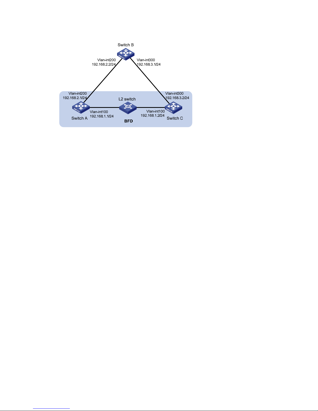
43
Figure 11 Network diagram
Configuration procedure
1. Configure IP addresses for interfaces. (Details not shown.)
2. Configure basic RIP:
# Configure Switch A.
<SwitchA> system-view
[SwitchA] rip 1
[SwitchA-rip-1] version 2
[SwitchA-rip-1] undo summary
[SwitchA-rip-1] network 192.168.1.0
[SwitchA-rip-1] quit
[SwitchA] interface vlan-interface 100
[SwitchA-Vlan-interface100] rip bfd enable
[SwitchA-Vlan-interface100] quit
[SwitchA] rip 2
[SwitchA-rip-2] version 2
[SwitchA-rip-2] undo summary
[SwitchA-rip-2] network 192.168.2.0
[SwitchA-rip-2] quit
# Configure Switch B.
<SwitchB> system-view
[SwitchB] rip 1
[SwitchB-rip-1] version 2
[SwitchB-rip-1] undo summary
[SwitchB-rip-1] network 192.168.2.0
[SwitchB-rip-1] network 192.168.3.0
[SwitchB-rip-1] quit
# Configure Switch C.
<SwitchC> system-view
[SwitchC] rip 1
[SwitchC-rip-1] version 2
[SwitchC-rip-1] undo summary
[SwitchC-rip-1] network 192.168.1.0
Page 55

44
[SwitchC-rip-1] network 192.168.3.0
[SwitchC-rip-1] import-route static
[SwitchC-rip-1] quit
3. Configure BFD parameters on VLAN-interface 100 of Switch A.
[SwitchA] bfd session init-mode active
[SwitchA] bfd echo-source-ip 11.11.11.11
[SwitchA] interface vlan-interface 100
[SwitchA-Vlan-interface100] bfd min-transmit-interval 500
[SwitchA-Vlan-interface100] bfd min-receive-interval 500
[SwitchA-Vlan-interface100] bfd detect-multiplier 7
[SwitchA-Vlan-interface100] quit
[SwitchA] quit
4. Configure a static route on Switch C.
[SwitchC] ip route-static 120.1.1.1 24 null 0
Verifying the configuration
# Display the BFD session information on Switch A.
<SwitchA> display bfd session
Total Session Num: 1 Up Session Num: 1 Init Mode: Active
IPv4 Session Working Under Echo Mode:
LD SourceAddr DestAddr State Holdtime Interface
4 192.168.1.1 192.168.1.2 Up 2000ms Vlan100
# Display RIP routes destined for 120.1.1.0/24 on Switch A.
<SwitchA> display ip routing-table 120.1.1.0 24 verbose
Summary Count : 1
Destination: 120.1.1.0/24
Protocol: RIP Process ID: 1
SubProtID: 0x1 Age: 04h20m37s
Cost: 1 Preference: 100
Tag: 0 State: Active Adv
OrigTblID: 0x0 OrigVrf: default-vrf
TableID: 0x2 OrigAs: 0
NBRID: 0x26000002 LastAs: 0
AttrID: 0xffffffff Neighbor: 192.168.1.2
Flags: 0x1008c OrigNextHop: 192.168.1.2
Label: NULL RealNextHop: 192.168.1.2
BkLabel: NULL BkNextHop: N/A
Tunnel ID: Invalid Interface: Vlan-interface100
BkTunnel ID: Invalid BkInterface: N/A
The output shows that Switch A communicates with Switch C through VLAN-interface 100. Then the link
over VLAN-interface 100 fails.
# Display RIP routes destined for 120.1.1.0/24 on Switch A.
Page 56
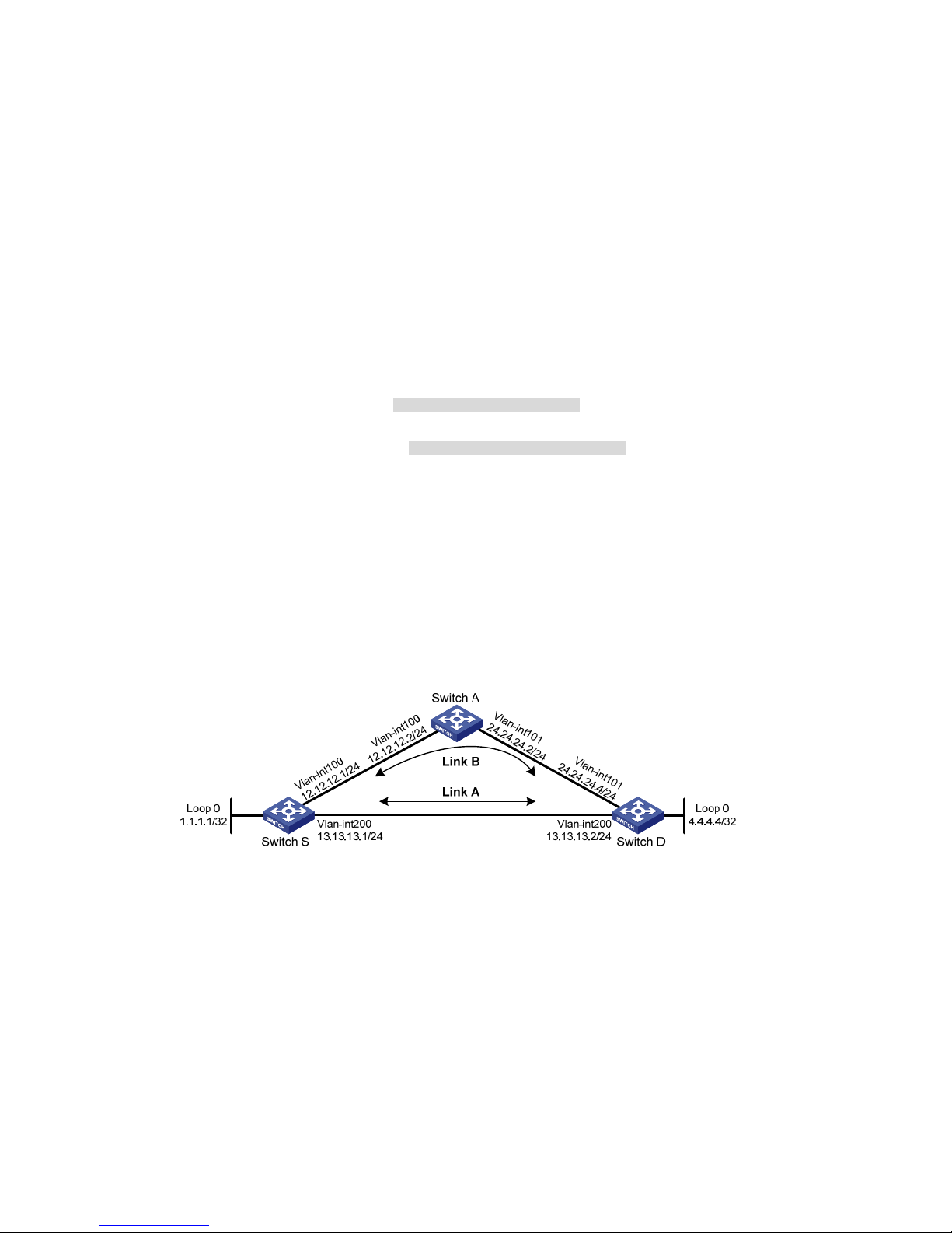
45
<SwitchA> display ip routing-table 120.1.1.0 24 verbose
Summary Count : 1
Destination: 120.1.1.0/24
Protocol: RIP Process ID: 2
SubProtID: 0x1 Age: 04h20m37s
Cost: 1 Preference: 100
Tag: 0 State: Active Adv
OrigTblID: 0x0 OrigVrf: default-vrf
TableID: 0x2 OrigAs: 0
NBRID: 0x26000002 LastAs: 0
AttrID: 0xffffffff Neighbor: 192.168.2.2
Flags: 0x1008c OrigNextHop: 192.168.2.2
Label: NULL RealNextHop: 192.168.2.2
BkLabel: NULL BkNextHop: N/A
Tunnel ID: Invalid Interface: Vlan-interface200
BkTunnel ID: Invalid BkInterface: N/A
The output shows that Switch A communicates with Switch C through VLAN-interface 200.
Configuring RIP FRR
Network requirements
As shown in Figure 12, Switch S, Switch A, and Switch D run RIPv2. Configure RIP FRR so that when Link
A fails, services can be switched to Link B immediately.
Figure 12 Network diagram
Configuration procedure
1. Configure IP addresses and subnet masks for interfaces on the switches. (Details not shown.)
2. Configure RIPv2 on the switches to make sure Switch A, Switch D, and Switch S can communicate
with each other at Layer 3. (Details not shown.)
3. Configure RIP FRR:
# Configure Switch S.
<SwitchS> system-view
[SwitchS] bfd echo-source-ip 1.1.1.1
[SwitchS] ip prefix-list abc index 10 permit 4.4.4.4 32
[SwitchS] route-policy frr permit node 10
[SwitchS-route-policy-frr-10] if-match ip address prefix-list abc
Page 57

46
[SwitchS-route-policy-frr-10] apply fast-reroute backup-interface vlan-interface
100 backup-nexthop 12.12.12.2
[SwitchS-route-policy-frr-10] quit
[SwitchS] rip 1
[SwitchS-rip-1] fast-reroute route-policy frr
[SwitchS-rip-1] quit
# Configure Switch D.
<SwitchD> system-view
[SwitchD] bfd echo-source-ip 4.4.4.4
[SwitchD] ip prefix-list abc index 10 permit 1.1.1.1 32
[SwitchD] route-policy frr permit node 10
[SwitchD-route-policy-frr-10] if-match ip address prefix-list abc
[SwitchD-route-policy-frr-10] apply fast-reroute backup-interface vlan-interface
101 backup-nexthop 24.24.24.2
[SwitchD-route-policy-frr-10] quit
[SwitchD] rip 1
[SwitchD-rip-1] fast-reroute route-policy frr
[SwitchD-rip-1] quit
Verifying the configuration
# Display route 4.4.4.4/32 on Switch S to view the backup next hop information.
[SwitchS] display ip routing-table 4.4.4.4 verbose
Summary Count : 1
Destination: 4.4.4.4/32
Protocol: RIP Process ID: 1
SubProtID: 0x1 Age: 04h20m37s
Cost: 1 Preference: 100
Tag: 0 State: Active Adv
OrigTblID: 0x0 OrigVrf: default-vrf
TableID: 0x2 OrigAs: 0
NBRID: 0x26000002 LastAs: 0
AttrID: 0xffffffff Neighbor: 13.13.13.2
Flags: 0x1008c OrigNextHop: 13.13.13.2
Label: NULL RealNextHop: 13.13.13.2
BkLabel: NULL BkNextHop: 12.12.12.2
Tunnel ID: Invalid Interface: Vlan-interface200
BkTunnel ID: Invalid BkInterface: Vlan-interface100
# Display route 1.1.1.1/32 on Switch D to view the backup next hop information.
[SwitchD] display ip routing-table 1.1.1.1 verbose
Summary Count : 1
Destination: 1.1.1.1/32
Protocol: RIP Process ID: 1
SubProtID: 0x1 Age: 04h20m37s
Cost: 1 Preference: 100
Page 58

47
Tag: 0 State: Active Adv
OrigTblID: 0x0 OrigVrf: default-vrf
TableID: 0x2 OrigAs: 0
NBRID: 0x26000002 LastAs: 0
AttrID: 0xffffffff Neighbor: 13.13.13.1
Flags: 0x1008c OrigNextHop: 13.13.13.1
Label: NULL RealNextHop: 13.13.13.1
BkLabel: NULL BkNextHop: 24.24.24.2
Tunnel ID: Invalid Interface: Vlan-interface200
BkTunnel ID: Invalid BkInterface: Vlan-interface101
Page 59

48
Configuring OSPF
Open Shortest Path First (OSPF) is a link-state IGP developed by the OSPF working group of the IETF.
OSPF version 2 is used for IPv4. OSPF refers to OSPFv2 throughout this chapter.
Overview
OSPF offers the following features:
• Wide scope—Supports various network sizes and up to several hundred routers in an OSPF routing
domain.
• Fast convergence—Advertises routing updates instantly upon network topology changes.
• Loop free—Computes routes with the SPF algorithm to avoid routing loops.
• Area-based network partition—Splits an AS into multiple areas to facilitate management. This
feature reduces the LSDB size on routers to save memory and CPU resources, and reduces route
updates transmitted between areas to save bandwidth.
• ECMP routing—Supports multiple equal-cost routes to a destination.
• Routing hierarchy—Supports a 4-level routing hierarchy that prioritizes routes into intra-area,
inter-area, external Type-1, and external Type-2 routes.
• Authentication—Supports area- and interface-based packet authentication to ensure secure packet
exchange.
• Support for multicasting—Multicasts protocol packets on some types of links to avoid impacting
other devices.
OSPF packets
OSPF messages are carried directly over IP. The protocol number is 89.
OSPF uses the following packet types:
• Hello—Periodically sent to find and maintain neighbors, containing timer values, information about
the DR, BDR, and known neighbors.
• Database description (DD)—Describes the digest of each LSA in the LSDB, exchanged between two
routers for data synchronization.
• Link state request (LSR)—Requests needed LSAs from a neighbor. After exchanging the DD packets,
the two routers know which LSAs of the neighbor are missing from their LSDBs. They then exchange
LSR packets requesting the missing LSAs. The LSA packet contains the digest of the missing LSAs.
• Link state update (LSU)—Transmits the requested LSAs to the neighbor.
• Link state acknowledgment (LSAck)—Acknowledges received LSU packets. It contains the headers
of received LSAs (an LSAck packet can acknowledge multiple LSAs).
Page 60

49
LSA types
OSPF advertises routing information in Link State Advertisements (LSAs). The following LSAs are
commonly used:
• Router LSA—Type-1 LSA, originated by all routers and flooded throughout a single area only. This
LSA describes the collected states of the router's interfaces to an area.
• Network LSA—Type-2 LSA, originated for broadcast and NBMA networks by the designated router,
and flooded throughout a single area only. This LSA contains the list of routers connected to the
network.
• Network Summary LSA—Type-3 LSA, originated by Area Border Routers (ABRs), and flooded
throughout the LSA's associated area. Each summary-LSA describes a route to a destination outside
the area, yet still inside the AS (an inter-area route).
• ASBR Summary LSA—Type-4 LSA, originated by ABRs and flooded throughout the LSA's
associated area. Type 4 summary-LSAs describe routes to Autonomous System Boundary Router
(ASBR).
• AS External LSA—Type-5 LSA, originated by ASBRs, and flooded throughout the AS (except stub
and NSSA areas). Each AS-external-LSA describes a route to another AS.
• NSSA LSA—Type-7 LSA, as defined in RFC 1587, originated by ASBRs in NSSAs and flooded
throughout a single NSSA. NSSA LSAs describe routes to other ASs.
• Opaque LSA—A proposed type of LSA. Its format consists of a standard LSA header and
application specific information. Opaque LSAs are used by the OSPF protocol or by some
applications to distribute information into the OSPF routing domain. The opaque LSA includes Type
9, Type 10, and Type 11. The Type 9 opaque LSA is flooded into the local subnet, the Type 10 is
flooded into the local area, and the Type 11 is flooded throughout the AS.
OSPF areas
In large OSPF routing domains, SPF route computations consume too many storage and CPU resources,
and enormous OSPF packets generated for route synchronization occupy excessive bandwidth.
To resolve these issues, OSPF splits an AS into multiple areas. Each area is identified by an area ID. The
boundaries between areas are routers rather than links. A network segment (or a link) can only reside in
one area as shown in Figure 13.
Y
ou can configure route summarization on ABRs to reduce the number of LSAs advertised to other areas
and minimize the effect of topology changes.
Page 61

50
Figure 13 Area-based OSPF network partition
Backbone area and virtual links
Each AS has a backbone area that distributes routing information between non-backbone areas. Routing
information between non-backbone areas must be forwarded by the backbone area. OSPF includes the
following requirements:
• All non-backbone areas must maintain connectivity to the backbone area.
• The backbone area must maintain connectivity within itself.
In practice, these requirements might not be satisfied due to lack of physical links. OSPF virtual links can
resolve this issue.
A virtual link is established between two ABRs through a non-backbone area. It must be configured on
both ABRs to take effect. The non-backbone area is called a transit area.
In Figure 14,
Area 2 has no direct physical link to the backbone area 0. You can configure a virtual link
between the two ABRs to connect Area 2 to the backbone area.
Figure 14 Virtual link application 1
Virtual links can also be used to provide redundant links. If the backbone area cannot maintain internal
connectivity due to the failure of a physical link, you can configure a virtual link to replace the failed
physical link, as shown in Figure 15.
Area 0
Area 1
Area 2
Area 3
Area 4
Page 62

51
Figure 15 Virtual link application 2
The virtual link between the two ABRs acts as a point-to-point connection. You can configure interface
parameters, such as hello interval, on the virtual link as they are configured on a physical interface.
The two ABRs on the virtual link unicast OSPF packets to each other, and the OSPF routers in between
convey these OSPF packets as normal IP packets.
Stub area and totally stub area
A stub area does not distribute Type-5 LSAs to reduce the routing table size and LSAs advertised within
the area. The ABR of the stub area advertises a default route in a Type-3 LSA so that the routers in the area
can reach external networks through the default route.
To further reduce the routing table size and advertised LSAs, you can configure the stub area as a totally
stub area. The ABR of a totally stub area does no advertise inter-area routes or external routes. It
advertises a default route in a Type-3 LSA so that the routers in the area can reach external networks
through the default route.
NSSA area and totally NSSA area
An NSSA area does not import AS external LSAs (Type-5 LSAs) but can import Type-7 LSAs generated by
the NSSA ASBR. The NSSA ABR translates Type-7 LSAs into Type-5 LSAs and advertises the Type-5 LSAs
to other areas.
In Figure 16, t
he OSPF AS contains Area 1, Area 2, and Area 0. The other two ASs run RIP. Area 1 is an
NSSA area where the ASBR redist ri butes RIP routes i n Type-7 LSA s into Area 1. Upon receiving th e Type-7
LSAs, the NSSA ABR translates them to Type-5 LSAs, and advertises the Type-5 LSAs to Area 0.
The ASBR of Area 2 redistributes RIP routes in Type -5 LSAs into the OSPF routing domain. However, Area
1 does not receive Type-5 LSAs because it is an NSSA area.
Figure 16 NSSA area
Router types
OSPF routers are classified into the following types based on their positions in the AS:
Area 0
Area 1
Virtual link
R2
R1
Page 63

52
• Internal router—All interfaces on an internal router belong to one OSPF area.
• ABR—Belongs to more than two areas, one of which must be the backbone area. ABR connects the
backbone area to a non-backbone area. An ABR and the backbone area can be connected
through a physical or logical link.
• Backbone router—At least one interface of a backbone router must reside in the backbone area.
All ABRs and internal routers in area 0 are backbone routers.
• ASBR—Exchanges routing information with another AS is an ASBR. An ASBR might not reside on
the border of the AS. It can be an internal router or an ABR.
Figure 17 OSPF router types
Route types
OSPF prioritizes routes into the following route levels:
• Intra-area route
• Inter-area route
• Type-1 external route
• Type-2 external route
The intra-area and inter-area routes describe the network topology of the AS. The external routes describe
routes to external ASs.
A Type-1 external route has high credibility. The cost from a router to the destination of a Type-1 external
route = the cost from the router to the corresponding ASBR + the cost from the ASBR to the destination of
the external route.
A Type-2 external route has low credibility. OSPF considers the cost from the ASBR to the destination of
a Type-2 external route is much greater than the cost from the ASBR to an OSPF internal router. The cost
from the internal router to the destination of the Type-2 external route = the cost from the ASBR to the
Area 1
Area 2
Area 3
Area 4
Backbone router
ASBR
IS-IS
RIP
Internal router
ABR
Area 0
Page 64

53
destination of the Type-2 external route. If two Type-2 routes to the same destination have the same cost,
OSPF takes the cost from the router to the ASBR into consideration to determine the best route.
Route calculation
OSPF computes routes in an area as follows:
• Each router generates LSAs based on the network topology around itself, and sends them to other
routers in update packets.
• Each OSPF router collects LSAs from other routers to compose an LSDB. An LSA describes the
network topology around a router, and the LSDB describes the entire network topology of the area.
• Each router transforms the LSDB to a weighted directed graph that shows the topology of the area.
All the routers within the area have the same graph.
• Each router uses the SPF algorithm to compute a shortest path tree that shows the routes to the nodes
in the area. The router itself is the root of the tree.
OSPF network types
OSPF classifies networks into the following types, depending on different link layer protocols:
• Broadcast—If the link layer protocol is Ethernet or FDDI, OSPF considers the network type as
broadcast by default. On a broadcast network, hello, LSU, and LSAck packets are multicast to
224.0.0.5 that identifies all OSPF routers or to 224.0.0.6 that identifies the DR; DD packets and LSR
packets are unicast.
• NBMA—If the link layer protocol is Frame Relay, ATM, or X.25, OSPF considers the network type
as NBMA by default. OSPF packets are unicast on a NBMA network.
• P2MP—No link is P2MP type by default. P2MP must be a conversion from other network types such
as NBMA. On a P2MP network, OSPF packets are multicast to 224.0.0.5.
• P2P—If the link layer protocol is PPP or HDLC, OSPF considers the network type as P2P. On a P2P
network, OSPF packets are multicast to 224.0.0.5.
The following are the differences between NBMA and P2MP networks:
• NBMA networks are fully meshed. P2MP networks are not required to be fully meshed.
• NBMA networks require DR and BDR election. P2MP networks do not have DR or BDR.
• On a NBMA network, OSPF packets are unicast, and neighbors are manually configured. On a
P2MP network, OSPF packets are multicast by default, and you can configure OSPF to unicast
protocol packets.
DR and BDR
On a broadcast or NBMA network, any two routers must establish an adjacency to exchange routing
information with each other. If n routers are present on the network, n(n-1)/2 adjacencies are established.
Any topology change on the network results in an increase in traffic for route synchronization, consuming
many system and bandwidth resources.
The DR and BDR mechanisms can solve this problem.
• DR—Elected to advertise routing information among other routers. If the DR fails, routers on the
network must elect another DR and synchronize information with the new DR. Using this mechanism
alone is time-consuming and prone to route calculation errors.
Page 65
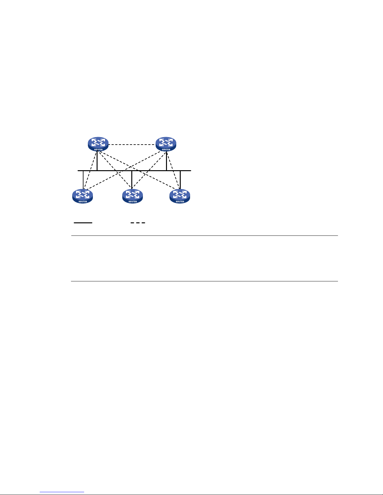
54
• BDR—Elected along with the DR to establish adjacencies with all other routers. If the DR fails, the
BDR immediately becomes the new DR, and other routers elect a new BDR.
Routers other than the DR and BDR are called "DROthers." They do not establish adjacencies with one
another, so the number of adjacencies is reduced.
The role of a router is subnet (or interface) specific. It might be a DR on one interface and a BDR or
DROther on another interface.
In Figure 18, s
olid lines are Ethernet physical links, and dashed lines represent OSPF adjacencies. With
the DR and BDR, only seven adjacencies are established.
Figure 18 DR and BDR in a network
NOTE:
In OSPF, "neighbor" and "adjacency" are different concepts. After startup, OSPF sends a hello packet on
each OSPF interface. A receiving router checks parameters in the packet. If the parameters match its own,
the receiving router considers the sending router an OSPF neighbor. Two OSPF neighbors establish an
adjacency relationship after they synchronize their LSDBs through exchange of DD packets and LSAs.
DR and BDR election
DR election is performed on broadcast or NBMA networks but not on P2P and P2MP networks.
Routers in a broadcast or NBMA network elect the DR and BDR by router priority and ID. Routers with a
router priority value higher than 0 are candidates for DR and BDR election.
The election votes are hello packets. Each router sends the DR elected by itself in a hello packet to all the
other routers. If two routers on the network declare themselves as the DR, the router with the higher router
priority wins. If router priorities are the same, the router with the higher router ID wins.
If a router with a higher router priority is added to the network after DR and BDR election, the router
cannot become the DR or BDR immediately as no DR election is performed for it. Therefore, the DR of a
network might not be the router with the highest priority, and the BDR might not be the router with the
second highest priority.
Protocols and standards
• RFC 1765, OSPF Database Overflow
• RFC 2328, OSPF Version 2
• RFC 3101, OSPF Not-So-Stubby Area (NSSA) Option
DR BDR
DR other DR otherDR other
Physical links Adjacencies
Page 66

55
• RFC 3137, OSPF Stub Router Advertisement
• RFC 4811, OSPF Out-of-Band LSDB Resynchronization
• R F C 4 812, OSPF Restart Signaling
• RFC 4813, OSPF Link-Local Signaling
OSPF configuration task list
To run OSPF, you must first enable OSPF on the router. Make a proper configuration plan to avoid
incorrect settings that can result in route blocking and routing loops.
To configure OSPF, perform the following tasks:
Tasks at a glance
(Required.) Enabling OSPF
(Optional.) Configuring OSPF areas:
• Configuring a stub area
• Configuring an NSSA area
• Configuring a virtual link
(Optional.) Configuring OSPF network types:
• Configuring the broadcast network type for an interface
• Configuring the NBMA network type for an interface
• Configuring the P2MP network type for an interface
• Configuring the P2P network type for an interface
(Optional.) Configuring OSPF route control:
• Configuring OSPF route summarization
{ Configuring route summarization on an ABR
{ Configuring route summarization when redistributing routes into OSPF on an ASBR
• Configuring inbound OSPF route filtering
• Configuring Type-3 LSA filtering
• Configuring an OSPF cost for an interface
• Configuring the maximum number of ECMP routes
• Configuring OSPF preference
• Configuring OSPF route redistribution
{ Configuring OSPF to redistribute routes from another routing protocol
{ Configuring OSPF to redistribute a default route
{ Configuring default parameters for redistributed routes
• Advertising a host route
Page 67

56
Tasks at a glance
(Optional.) Tuning and optimizing OSPF networks:
• Configuring OSPF timers
• Specifying LSA transmission delay
• Specifying SPF calculation interval
• Specifying the LSA arrival interval
• Specifying the LSA generation interval
• Disabling interfaces from receiving and sending OSPF packets
• Configuring stub routers
• Configuring OSPF authentication
• Adding the interface MTU into DD packets
• Configuring the maximum number of external LSAs in LSDB
• Configuring OSPF exit overflow interval
• Enabling compatibility with RFC 1583
• Logging neighbor state changes
• Configuring OSPF network management
• Configuring the LSU transmit rate
• Enabling OSPF ISPF
(Optional.) Configuring OSPF GR:
• Configuring the OSPF GR Restarter
• Configuring OSPF GR Helper
• Triggering OSPF GR
(Optional.) Configuring BFD for OSPF
(Optional.) Configuring OSPF FRR
Enabling OSPF
Enable OSPF before you perform other OSPF configuration tasks.
Configuration prerequisites
Configure the link layer protocol and IP addresses for interfaces to ensure IP connectivity between
neighboring nodes.
Configuration guidelines
Complete the following tasks to enable an interface to run an OSPF process in an area:
• Enable the OSPF process.
• Create the area for the OSPF process.
• Add the network segment where the interface resides to the area. The OSPF process advertises the
direct route of the interface.
• Specify a router ID, the unique identifier of the router in the AS.
You can also specify a router ID when you create an OSPF process.
Page 68

57
• If you specify a router ID when you create an OSPF process, any two routers in an AS must have
different router IDs. A common practice is to specify the IP address of an interface as the router ID.
• If you specify no router ID when you create the OSPF process, the global router ID is used. HP
recommends specifying a router ID when you create the OSPF process.
OSPF can run multiple processes and supports VPNs:
• To run multiple OSPF processes, you must specify an ID for each process. The process IDs take effect
locally and has no influence on packet exchange between routers. Two routers with different
process IDs can exchange packets.
• VPN support enables an OSPF process to run in a specified VPN. For more information about VPN,
see MCE Configuration Guide.
Configuration procedure
To enable OSPF:
Step Command
Remarks
1. Enter system view.
system-view N/A
2. (Optional.) Configure a
global router ID.
router id router-id
By default, no global r o u t e r ID is configured.
If no global router ID is configured, the
highest loopback interface IP address, if
any, is used as the router ID. If no loopback
interface IP address is available, the highest
physical interface IP address is used,
regardless of the interface status (up or
down).
3. Enable an OSPF process
and enter OSPF view.
ospf [ process-id | router-id
router-id | vpn-instance
vpn-instance-name ] *
By default, no OSPF process is enabled.
4. (Optional.) Configure a
description for the OSPF
process.
description description
By default, no description is configured for
the OSPF process.
HP recommends configuring a description
for each OSPF process.
5. Create an OSPF area and
enter OSPF area view.
area area-id
By default, no OSPF area is created.
6. (Optional.) Configure a
description for the area.
description description
By default, no description is configured for
the area.
HP recommends configuring a description
for each OSPF area.
7. Specify a network to enable
the interface attached to the
network to run the OSPF
process in the area.
network ip-address
wildcard-mask
By default, no network is specified.
A network can be added to only one area.
Configuring OSPF areas
Before you configure an OSPF area, complete the following tasks:
Page 69

58
• Configure IP addresses for interfaces to ensure IP connectivity between neighboring nodes.
• Enable OSPF.
Configuring a stub area
You can configure a non-backbone area at an AS edge as a stub area. To do so, issue the stub command
on all routers attached to the area. The routing table size is reduced because Type-5 LSAs will not be
flooded within the stub area. The ABR generates a default route into the stub area so all packets destined
outside of the AS are sent through the default route.
To further reduce the routing table size and routing information exchanged in the stub area, configure a
totally stub area by using the stub [ no-summary ] command on the ABR. AS external routes and
inter-area routes will not be distributed into the area. All the packets destined outside of the AS or area
will be sent to the ABR for forwarding.
A stub or totally stub area cannot have an ASBR because external routes cannot be distributed into the
area.
Virtual links cannot transit a stub area or totally stub area.
To configure an OSPF stub area:
Step Command
Remarks
1. Enter system view.
system-view N/A
2. Enter OSPF view.
ospf [ process-id | router-id
router-id | vpn-instance
vpn-instance-name ] *
N/A
3. Enter area view.
area area-id
N/A
4. Configure the area as a stub
area.
stub
[ default-route-advertise-always
| no-summary ] *
By default, no stub area is configured.
5. (Optional.) Specify a cost
for the default route
advertised to the stub area.
default-cost cost
The default setting is 1.
The default-cost cost command takes
effect only on the ABR of a stub area or
totally stub area.
Configuring an NSSA area
A stub area cannot import external routes, but an NSSA area can import external routes into the OSPF
routing domain while retaining other stub area characteristics.
Do not configure the backbone area as an NSSA area or totally NSSA area.
To configure an NSSA area, configure the nssa command on all the routers attached to the area.
To configure a totally NSSA area, configure the nssa command on all the routers attached to the area
and configure the nssa no-summary command on the ABR. The ABR of a totally NSSA area does not
advertise inter-area routes into the area.
Virtual links cannot transit a stub area or totally stub area.
To configure an NSSA area:
Page 70

59
Step Command
Remarks
1. Enter system view.
system-view N/A
2. Enter OSPF view.
ospf [ process-id | router-id
router-id | vpn-instance
vpn-instance-name ] *
N/A
3. Enter area view.
area area-id
N/A
4. Configure the area as an
NSSA area.
nssa [ default-route-advertise |
no-import-route | no-summary |
translate-always |
translator-stability-interval value ]
*
By default, no area is configured as
an NSSA area.
5. (Optional.) Specify a cost for
the default route advertised
to the NSSA area.
default-cost cost
The default setting is 1.
This command takes effect only on
the ABR/ASBR of an NSSA or totally
NSSA area.
Configuring a virtual link
Virtual links are configured for connecting backbone area routers that have no direct physical links.
Virtual links cannot transit a stub area, totally stub area, NSSA area, or totally NSSA area.
To configure a virtual link:
Step Command
Remarks
1. Enter system view.
system-view N/A
2. Enter OSPF view.
ospf [ process-id | router-id
router-id | vpn-instance
vpn-instance-name ] *
N/A
3. Enter area view.
area area-id
N/A
4. Configure a virtual link.
vlink-peer router-id [ dead seconds
| hello seconds | { hmac-md5 |
md5 } key-id { cipher cipher-string
| plain plain-string } | retransmit
seconds | simple { cipher
cipher-string | plain plain-string } |
trans-delay seconds ] *
By default, no virtual link is
configured.
Configure this command on both
ends of a virtual link, and the hello
and dead intervals must be identical
on both ends of the virtual link.
The authentication mode (MD5 or
simple) of the virtual link is
determined by the authentication
mode configured for the backbone
area.
Configuring OSPF network types
OSPF classifies networks into the following types based on the link layer protocol:
Page 71

60
• Broadcast—When the link layer protocol is Ethernet or FDDI, OSPF classifies the network type as
broadcast by default.
• NBMA—When the link layer protocol is Frame Relay, ATM, or X.25, OSPF classifies the network
type as NBMA by default.
• P2P—When the link layer protocol is PPP, LAPB, or HDLC, OSPF classifies the network type as P2P
by default.
When you change the network type of an interface, follow these guidelines:
• When an NBMA network becomes fully meshed, change the network type to broadcast to avoid
manual configuration of neighbors.
• If any routers in a broadcast network do not support multicasting, change the network type to
NBMA.
• An NBMA network must be fully meshed. OSPF requires that an NBMA network be fully meshed.
If a network is partially meshed, change the network type to P2MP.
• If a router on an NBMA network has only one neighbor, you can change the network type to P2P
to save costs.
Two broadcast-, NBMA-, and P2MP-interfaces can establish a neighbor relationship only when they are
on the same network segment.
Configuration prerequisites
Before you configure OSPF network types, complete the following tasks:
• Configure IP addresses for interfaces to ensure IP connectivity between neighboring nodes.
• Enable OSPF.
Configuring the broadcast network type for an interface
Step Command
Remarks
1. Enter system view.
system-view N/A
2. Enter interface view.
interface interface-type
interface-number
N/A
3. Configure the OSPF network
type for the interface as
broadcast.
ospf network-type broadcast
By default, the network type of an
interface depends on the link layer
protocol.
4. (Optional.) Configure a router
priority for the interface.
ospf dr-priority priority The default router priority is 1.
Configuring the NBMA network type for an interface
After you configure the network type as NBMA, you must specify neighbors and their router priorities
because NBMA interfaces cannot find neighbors by broadcasting hello packets.
To configure the NBMA network type for an interface:
Page 72

61
Step Command
Remarks
1. Enter system view.
system-view N/A
2. Enter interface view.
interface interface-type
interface-number
N/A
3. Configure the OSPF
network type for the
interface as NBMA.
ospf network-type nbma
By default, the network type of an
interface depends on the link layer
protocol.
4. (Optional.) Configure a
router priority for the
interface.
ospf dr-priority priority
The default setting is 1.
The router priority configured with this
command is for DR election.
5. Return to system view.
quit N/A
6. Enter OSPF view.
ospf [ process-id | router-id
router-id | vpn-instance
vpn-instance-name ] *
N/A
7. Specify a neighbor and its
router priority.
peer ip-address [ cost value |
dr-priority dr-priority ]
By default, no neighbor is specified.
The priority configured with this
command indicates whether a
neighbor has the election right or not. If
you configure the router priority for a
neighbor as 0, the local router
determines the neighbor has no
election right, and does not send hello
packets to this neighbor. However, if
the local router is the DR or BDR, it still
sends hello packets to the neighbor for
neighbor relationship establishment.
Configuring the P2MP network type for an interface
Step Command
Remarks
1. Enter system view.
system-view N/A
2. Enter interface view.
interface interface-type
interface-number
N/A
3. Configure the OSPF network
type for the interface as
P2MP.
ospf network-type p2mp [ unicast ]
By default, the network type of an
interface depends on the link layer
protocol.
After you configure the OSPF
network type for an interface as
P2MP unicast, all packets are unicast
over the interface. The interface
cannot broadcast hello packets to
discover neighbors, so you must
manually specify the neighbors.
4. Exit to system view.
quit N/A
Page 73

62
Step Command
Remarks
5. Enter OSPF view.
ospf [ process-id | router-id
router-id | vpn-instance
vpn-instance-name ] *
N/A
6. (Optional.) Specify a
neighbor and its router
priority.
peer ip-address [ cost value |
dr-priority dr-priority ]
By default, no neighbor is specified.
This step must be performed if the
network type is P2MP unicast, and is
optional if the network type is P2MP.
Configuring the P2P network type for an interface
Step Command
Remarks
1. Enter system view.
system-view N/A
2. Enter interface view.
interface interface-type
interface-number
N/A
3. Configure the OSPF network
type for the interface as P2P.
ospf network-type p2p
By default, the network type of an
interface depends on the link layer
protocol.
Configuring OSPF route control
This section describes how to control the advertisement and reception of OSPF routing information, as
well as route redistribution from other protocols.
Configuration prerequisites
Before you configure OSPF route control, complete the following tasks:
• Configure IP addresses for interfaces to ensure IP connectivity between neighboring nodes.
• Enable OSPF.
• Configure filters if routing information filtering is needed.
Configuring OSPF route summarization
Configure route summarization on an ABR or ASBR to summarize contiguous networks into a single
network and distribute it to other areas.
Route summarization reduces the routing information exchanged between areas and the size of routing
tables, and improves routing performance. For example, three internal networks 19.1.1.0/24,
19.1.2.0/24, and 19.1.3.0/24 are available within an area. You can summarize the three networks into
network 19.1.0.0/16, and advertise the summary network to other areas.
Configuring route summarization on an ABR
After you configure a summary route on an ABR, the ABR generates a summary LSA instead of more
specific LSAs so that the scale of LSDBs on routers in other areas and the influence of topology changes
are reduced.
Page 74

63
To configure route summarization on an ABR:
Step Command
Remarks
1. Enter system view.
system-view N/A
2. Enter OSPF view.
ospf [ process-id | router-id router-id
| vpn-instance vpn-instance-name ] *
N/A
3. Enter OSPF area view.
area area-id N/A
4. Configure ABR route
summarization.
abr-summary ip-address { mask |
mask-length } [ advertise |
not-advertise ] [ cost cost ]
By default, no route summarization
is configured.
The command takes effect only on
an ABR.
Configuring route summarization when redistributing routes into OSPF on an ASBR
Without route summarization, an ASBR advertises each redistributed route in a separate ASE LSA. After
you configure a summary route, the ASBR advertises only the summary route in an ASE LSA instead of
more specific routes, reducing the number of LSAs in the LSDB.
The ASBR summarizes redistributed Type-5 LSAs that fall into the specified address range. If the ASBR is
in an NSSA area, it also summarizes Type-7 LSAs that fall into the specified address range. If the ASBR
is also the ABR, it summarizes Type-5 LSAs translated from Type-7 LSAs.
To configure route summarization when redistributing routes into OSPF on an ASBR:
Step Command
Remarks
1. Enter system view.
system-view N/A
2. Enter OSPF view.
ospf [ process-id | router-id router-id
| vpn-instance vpn-instance-name ]*
N/A
3. Configure ASBR route
summarization.
asbr-summary ip-address { mask |
mask-length } [ tag tag | not-advertise
| cost cost ] *
By default, no ASBR route
summarization is configured.
The command takes effect only on an
ASBR.
Configuring inbound OSPF route filtering
Perform this task to filter routes calculated using received LSAs.
The following filtering methods are available:
• Use an ACL or IP prefix list to filter routing information by destination address.
• Use the gateway keyword to filter routing information by next hop.
• Use an ACL or IP prefix list to filter routing information by destination address and at the same time
use the gateway keyword to filter routing information by next hop.
• Use a routing policy to filter routing information.
To configure OSPF to filter routes calculated using received LSAs:
Step Command
Remarks
1. Enter system view.
system-view N/A
Page 75

64
Step Command
Remarks
2. Enter OSPF view.
ospf [ process-id | router-id router-id |
vpn-instance vpn-instance-name ] *
N/A
3. Configure OSPF to
filter routes calculated
using received LSAs.
filter-policy { acl-number [ gateway
ip-prefix-name ] | gateway ip-prefix-name |
ip-prefix ip-prefix-name [ gateway
ip-prefix-name ] | route-policy
route-policy-name } import
By default, OSPF accepts all
routes calculated using
received LSAs.
Configuring Type-3 LSA filtering
Perform this task to filter Type-3 LSAs advertised to an area on an ABR.
To configure Type-3 LSA filtering:
Step Command
Remarks
1. Enter system view.
system-view N/A
2. Enter OSPF view.
ospf [ process-id | router-id router-id |
vpn-instance vpn-instance-name ] *
N/A
3. Enter area view.
area area-id N/A
4. Configure Type-3 LSA
filtering.
filter { acl-number | ip-prefix
ip-prefix-name } { import | export }
By default, the ABR does
not filter Type-3 LSAs.
Configuring an OSPF cost for an interface
Configure an OSPF cost for an interface by using either of the following methods:
• Configure the cost value in interface view.
• Configure a bandwidth reference value for the interface. OSPF computes the cost with this formula:
Interface OSPF cost = Bandwidth reference value (100 Mbps) / Interface bandwidth (Mbps). If the
calculated cost is greater than 65535, the value of 65535 is used. If the calculated cost is less than
1, the value of 1 is used. If no cost or bandwidth reference value is configured for an interface,
OSPF computes the interface cost based on the interface bandwidth and default bandwidth
reference value.
To configure an OSPF cost for an interface:
Step Command
Remarks
1. Enter system view.
system-view N/A
2. Enter interface view.
interface interface-type
interface-number
N/A
3. Configure an OSPF cost
for the interface.
ospf cost value
By default, the OSPF cost is calculated
according to the interface bandwidth. For
a loopback interface, the OSPF cost is 0
by default.
To configure a bandwidth reference value:
Page 76

65
Step Command
Remarks
1. Enter system view.
system-view N/A
2. Enter OSPF view.
ospf [ process-id | router-id router-id |
vpn-instance vpn-instance-name ] *
N/A
3. Configure a bandwidth
reference value.
bandwidth-reference value
The default setting is 100
Mbps.
Configuring the maximum number of ECMP routes
Perform this task to implement load sharing over ECMP routes.
To configure the maximum number of ECMP routes:
Step Command
Remarks
1. Enter system view.
system-view N/A
2. Enter OSPF view.
ospf [ process-id | router-id router-id |
vpn-instance vpn-instance-name ] *
N/A
3. Configure the maximum
number of ECMP routes.
maximum load-balancing maximum
By default, the
maximum number of
ECMP routes is the
same as that configured
in the max-ecmp-num
command. For more
information about the
max-ecmp-num
command, see IP
Routing Command
Reference.
Configuring OSPF preference
A router can run multiple routing protocols, and each protocol is assigned a preferen ce. If mul tiple routes
are available to the same destination, the one with the highest protocol preference is selected as the best
route.
To configure OSPF preference:
Step Command
Remarks
1. Enter system view.
system-view N/A
2. Enter OSPF view.
ospf [ process-id | router-id router-id
| vpn-instance vpn-instance-name ] *
N/A
3. Configure a
preference for OSPF.
preference [ ase ] [ route-policy
route-policy-name ] value
By default, the preference of OSPF
internal routes is 10 and the preference
of OSPF external routes is 150.
Page 77

66
Configuring OSPF route redistribution
On a router running OSPF and other routing protocols, you can configure OSPF to redistribute routes
from other protocols, such as RIP, IS-IS, BGP, static, and direct, and advertise them in Type-5 LSAs or
Type-7 LSAs. In addition, you can configure OSPF to filter redistributed routes so that OSPF advertises
only permitted routes.
IMPORTANT:
The import-route bgp command redistributes only EBGP routes. Because the import-route bgp
allow-ibgp command redistributes both EBGP and IBGP routes, and might cause routin
g
loops, use it with
caution.
Configuring OSPF to redistribute routes from another routing protocol
Step Command
Remarks
1. Enter system view.
system-view N/A
2. Enter OSPF view.
ospf [ process-id | router-id router-id |
vpn-instance vpn-instance-name ] *
N/A
3. Configure OSPF to
redistribute routes from
another routing protocol.
import-route protocol [ process-id |
all-processes | allow-ibgp ] [ cost cost |
route-policy route-policy-name | tag tag
| type type ] *
By default, no route redistribution
is configured.
This command redistributes only
active routes. To view information
about active routes, use the
display ip routing-table protocol
command.
4. (Optional.) Configure
OSPF to filter redistributed
routes.
filter-policy { acl-number | prefix-list
ip-prefix-name } export [ protocol
[ process-id ] ]
By default, OSPF accepts all
redistributed routes.
Configuring OSPF to redistribute a default route
The import-route command cannot redistribute a default external route. Perform this task to redistribute a
default route.
To redistribute a default route:
Step Command
Remarks
1. Enter system view.
system-view N/A
2. Enter OSPF view.
ospf [ process-id | router-id router-id |
vpn-instance vpn-instance-name ] *
N/A
3. Redistribute a default
route.
default-route-advertise [ [ [ always |
permit-calculate-other ] | cost cost |
route-policy route-policy-name | type
type ] * | summary cost cost ]
By default, no default route is
redistributed.
This command is applicable
only to VPNs. The PE router
advertises a default route in a
Type-3 LSA to a CE router.
Page 78

67
Configuring default parameters for redistributed routes
Perform this task to configure default parameters for redistributed routes, including cost, tag, and type.
Tags indicate information about protocols. For example, when redistributing BGP routes, OSPF uses tags
to identify AS IDs.
To configure the default parameters for redistributed routes:
Step Command
Remarks
1. Enter system view.
system-view N/A
2. Enter OSPF view.
ospf [ process-id | router-id router-id |
vpn-instance vpn-instance-name ] *
N/A
3. Configure the default
parameters for
redistributed routes (cost,
upper limit, tag, and
type).
default { cost cost | tag tag | type type } *
By default, the cost is 1, the
tag is 1, and the type is
Type-2.
Advertising a host route
Step Command
Remarks
1. Enter system view.
system-view N/A
2. Enter OSPF view.
ospf [ process-id | router-id
router-id | vpn-instance
vpn-instance-name ] *
N/A
3. Enter area view.
area area-id
N/A
4. Advertise a host route.
host-advertise ip-address cost
By default, no host route is
advertised.
Tuning and optimizing OSPF networks
You can use one of the following methods to optimize an OSPF network:
• Change OSPF packet timers to adjust the convergence speed and network load. On low-speed
links, consider the delay time for sending LSAs.
• Change the SPF calculation interval to reduce resource consumption caused by frequent network
changes.
• Configure OSPF authentication to improve security.
Configuration prerequisites
Before you configure OSPF network optimization, complete the following tasks:
• Configure IP addresses for interfaces to ensure IP connectivity between neighboring nodes.
• Enable OSPF.
Page 79

68
Configuring OSPF timers
An OSPF interface includes the following timers:
• Hello timer—Interval for sending hello packets. It must be identical on OSPF neighbors.
• Poll timer—Interval for sending hello packets to a neighbor that is down on the NBMA network.
• Dead timer—Interval within which if the interface receives no hello packet from the neighbor, it
declares the neighbor is down.
• LSA retransmission timer—Interval within which if the interface receives no acknowledgement
packets after sending a LSA to the neighbor, it retransmits the LSA.
To configure OSPF timers:
Step Command
Remarks
1. Enter system view.
system-view N/A
2. Enter interface
view.
interface interface-type
interface-number
N/A
3. Specify the hello
interval.
ospf timer hello seconds
By default:
• The hello interval on P2P and broadcast
interfaces is 10 seconds.
• The hello interval on P2MP and NBMA
interfaces is 30 seconds.
The default hello interval is restored when the
network type for an interface is changed.
4. Specify the poll
interval.
ospf timer poll seconds
The default setting is 120 seconds.
The poll interval is at least four times the hello
interval.
5. Specify the dead
interval.
ospf timer dead seconds
By default:
• The dead interval on P2P and broadcast
interfaces is 40 seconds.
• The dead interval on P2MP and NBMA
interfaces is 120 seconds.
The dead interval must be at least four times the
hello interval on an interface.
The default dead interval is restored when the
network type for an interface is changed.
6. Specify the
retransmission
interval.
ospf timer retransmit interval
The default setting is 5 seconds.
A retransmission interval setting that is too small
can cause unnecessary LSA retransmissions.
This interval is typically set bigger than the
round-trip time of a packet between two
neighbors.
Specifying LSA transmission delay
To avoid LSAs from aging out during transmission, set an LSA retransmission delay especially for low
speed links.
Page 80

69
To specify the LSA transmission delay on an interface:
Step Command
Remarks
1. Enter system view.
system-view N/A
2. Enter interface view.
interface interface-type
interface-number
N/A
3. Specify the LSA transmission
delay.
ospf trans-delay seconds
The default setting is 1 second.
Specifying SPF calculation interval
LSDB changes result in SPF calculations. When the topology changes frequently, a large amount of
network and router resources are occupied by SPF calculation. You can adjust the SPF calculation interval
to reduce the impact.
When network changes are not frequent, the minimum-interval is adopted. If network changes become
frequent, the SPF calculation interval is incremented by incremental-interval × 2
n-2
(n is the number of
calculation times) each time a calculation occurs until the maximum-interval is reached.
To configure the SPF calculation interval:
Step Command
Remarks
1. Enter system view.
system-view N/A
2. Enter OSPF view.
ospf [ process-id | router-id router-id
| vpn-instance vpn-instance-name ] *
N/A
3. Specify the SPF
calculation interval.
spf-schedule-interval
maximum-interval [ minimum-interval
[ incremental-interval ] ]
By default:
• The maximum interval is 5 seconds.
• The minimum interval is 50
milliseconds.
• The incremental interval is 200
milliseconds.
Specifying the LSA arrival interval
If OSPF receives an LSA that has the same LSA type, LS ID, and router ID as the previously received LSA
within the LSA arrival interval, OSPF discards the LSA to save bandwidth and route resources.
To configure the LSA arrival interval:
Step Command
Remarks
1. Enter system view.
system-view N/A
2. Enter OSPF view.
ospf [ process-id | router-id
router-id | vpn-instance
vpn-instance-name ] *
N/A
Page 81

70
Step Command
Remarks
3. Configure the LSA arrival
interval.
lsa-arrival-interval interval
The default setting is 1000
milliseconds.
Make sure this interval is smaller than
or equal to the interval set with the
lsa-generation-interval command.
Specifying the LSA generation interval
Adjust the LSA generation interval to protect network resources and routers from being overwhelmed by
LSAs at the time of frequent network changes.
When network changes are not frequent, LSAs are generated at the minimum-interval. If network
changes become frequent, the LSA generation interval is incremented by incremental-interval × 2
n-2
(n is
the number of generation times) each time a LSA generation occurs until the maximum-interval is
reached.
To configure the LSA generation interval:
Step Command
Remarks
1. Enter system view.
system-view N/A
2. Enter OSPF view.
ospf [ process-id | router-id router-id |
vpn-instance vpn-instance-name ] *
N/A
3. Configure the LSA
generation interval.
lsa-generation-interval
maximum-interval [ minimum-interval
[ incremental-interval ] ]
By default:
• The maximum interval is 5
seconds.
• The minimum interval is 0
milliseconds.
• The incremental interval is 0
milliseconds.
Disabling interfaces from receiving and sending OSPF packets
To enhance OSPF adaptability and reduce resource consumption, you can set an OSPF interface to
"silent." A silent OSPF interface blocks OSPF packets and cannot establish any OSPF neighbor
relationship. However, other interfaces on the router can still advertise direct routes of the interface in
Router LSAs.
To disable interfaces from receiving and sending routing information:
Step Command
Remarks
1. Enter system view.
system-view N/A
2. Enter OSPF view.
ospf [ process-id | router-id router-id
| vpn-instance vpn-instance-name ] *
N/A
Page 82

71
Step Command
Remarks
3. Disable interfaces from
receiving and sending
OSPF packets.
silent-interface { interface-type
interface-number | all }
By default, an OSPF interface can
receive and send OSPF packets.
The silent-interface command
disables only the interfaces
associated with the current process
rather than other processes.
Multiple OSPF processes can
disable the same interface from
receiving and sending OSPF
packets.
Configuring stub routers
A stub router is used for traffic control. It reports its status as a stub router to neighboring OSPF routers.
The neighboring routers do not use the stub router to forward data although they have a route to it.
Router LSAs from the stub router might contain different link type values. A value of 3 means a link to a
stub network, and the cost of the link will not be changed. A value of 1, 2 or 4 means a point-to-point link,
a link to a transit network, or a virtual link. On such links, a maximum cost value of 65535 is used.
Neighbors do not send packets to the stub router as long as they have a route with a smaller cost.
To configure a router as a stub router:
Step Command
Remarks
1. Enter system view.
system-view N/A
2. Enter OSPF view.
ospf [ process-id | router-id router-id |
vpn-instance vpn-instance-name ] *
N/A
3. Configure the router as a
stub router.
stub-router
By default, the router is not
configured as a stub router.
A stub router has no associations
with a stub area.
Configuring OSPF authentication
Configure OSPF packet authentication to ensure the packet exchange security.
After authentication is configured, OSPF only receives packets that pass authentication. Failed packets
cannot establish neighboring relationships.
You must configure the same area authentication mode on all the routers in an area. In addition, the
authentication mode and password for all interfaces attached to the same area must be identical.
To configure OSPF authentication:
Step Command
Remarks
1. Enter system view.
system-view N/A
2. Enter OSPF view.
ospf [ process-id | router-id router-id |
vpn-instance vpn-instance-name ] *
N/A
Page 83

72
Step Command
Remarks
3. Enter area view.
area area-id N/A
4. Configure area authentication
mode.
authentication-mode { md5 | simple }
By default, no
authentication is
configured.
5. Return to OSPF view.
quit N/A
6. Return to system view.
quit N/A
7. Enter interface view.
interface interface-type interface-number N/A
8. Configure interface
authentication mode.
• Configure simple authentication:
ospf authentication-mode simple { cipher
cipher-string | plain plain-string }
• Configure MD5 authentication:
ospf authentication-mode { hmac-md5 |
md5 } key-id { cipher cipher-string | plain
plain-string }
Use either method.
By default, no interface
authentication is
configured.
Adding the interface MTU into DD packets
By default, an OSPF interface adds a value of 0 into the interface MTU field of a DD packet rather than
the actual interface MTU. You can enable an interface to add its MTU into DD packets.
To add the interface MTU into DD packets:
Step Command
Remarks
1. Enter system view.
system-view N/A
2. Enter interface view.
interface interface-type
interface-number
N/A
3. Enable the interface to add its
MTU into DD packets.
ospf mtu-enable
By default, the interface adds an
MTU value of 0 into DD packets.
Configuring the maximum number of external LSAs in LSDB
Step Command
Remarks
1. Enter system view.
system-view N/A
2. Enter OSPF view.
ospf [ process-id | router-id router-id |
vpn-instance vpn-instance-name ] *
N/A
3. Specify the maximum number
of external LSAs in the LSDB.
lsdb-overflow-limit number
By default, the
maximum number of
external LSAs in the
LSDB is not limited.
Page 84

73
Configuring OSPF exit overflow interval
When the number of LSAs in the LSDB exceeds the upper limit, the LSDB is in an overflow state. To save
resources, OSPF does not receive any external LSAs and deletes the external LSAs generated by itself
when in this state.
Perform this task to configure the interval that OSPF exits overflow state.
To configure the OSPF exit overflow interval:
Step Command
Remarks
1. Enter system view.
system-view N/A
2. Enter OSPF view.
ospf [ process-id | router-id router-id |
vpn-instance vpn-instance-name ] *
N/A
3. Configure the OSPF exit
overflow interval.
lsdb-overflow-interval interval
The default setting is 300
seconds.
The value of 0 indicates that
OSPF does not exit overflow
state.
Enabling compatibility with RFC 1583
RFC 1583 specifies a different method than RFC 2328 for selecting an external route from multiple LSAs.
This task enables RFC 2328 to be compatible with RFC 1583 so that the intra-area route in the backbone
area is preferred. If they are not compatible, the intra-area route in a non-backbone area is preferred to
reduce the burden of the backbone area.
To avoid routing loops, HP recommends enabling or disabling RFC 1583-compatibility on all routers in
a routing domain.
To enable compatibility with RFC 1583:
Step Command
Remarks
1. Enter system view.
system-view N/A
2. Enter OSPF view.
ospf [ process-id | router-id router-id |
vpn-instance vpn-instance-name ] *
N/A
3. Enable compatibility
with RFC 1583.
rfc1583 compatible By default, this feature is enabled.
Logging neighbor state changes
Perform this task to enable output of log information to the terminal upon neighbor state changes.
To enable the logging of neighbor state changes:
Step Command
Remarks
1. Enter system view.
system-view N/A
Page 85

74
Step Command
Remarks
2. Enter OSPF view.
ospf [ process-id | router-id router-id |
vpn-instance vpn-instance-name ] *
N/A
3. Enable the logging of
neighbor state changes.
log-peer-change
By default, this feature is
enabled.
Configuring OSPF network management
OSPF network management allows you to save system resources by enabling trap generation to report
important events and configuring the maximum number of output traps for a specific time period.
To configure OSPF network management:
Step Command
Remarks
1. Enter system view.
system-view N/A
2. Bind OSPF MIB to an
OSPF process.
ospf mib-binding process-id
By default, OSPF MIB is bound to
the process with the smallest
process ID.
3. Enable SNMP traps
for OSPF.
snmp-agent trap enable ospf
[ authentication-failure | bad-packet |
config-error | grhelper-status-change |
grrestarter-status-change | if-state-change
| lsa-maxage | lsa-originate |
lsdb-approaching-overflow |
lsdb-overflow | neighbor-state-change |
nssatranslator-status-change | retransmit |
virt-authentication-failure | virt-bad-packet
| virt-config-error | virt-retransmit |
virtgrhelper-status-change |
virtif-state-change |
virtneighbor-state-change ] *
By default, SNMP traps for OSPF is
enabled.
4. Configure the
number of output
SNMP traps within a
specified time
interval.
snmp trap rate-limit interval trap-interval
count trap-number
By default, OSPF outputs up to 7
SNMP traps within 10 seconds.
Configuring the LSU transmit rate
Sending large numbers of LSU packets affects router performance and consumes too much network
bandwidth. You can configure the router to send LSU packets at a proper interval and limit the maximum
number of LSU packets sent out of an OSPF interface each time.
To configure the LSU transmit rate:
Step Command
Remarks
1. Enter system view.
system-view N/A
Page 86

75
Step Command
Remarks
2. Enter OSPF view.
ospf [ process-id | router-id router-id |
vpn-instance vpn-instance-name ] *
N/A
3. Configure the LSU
transmit rate.
transmit-pacing interval interval count count
By default, an OSPF interface
sends up to three LSU packets
every 20 milliseconds.
Enabling OSPF ISPF
When the topology changes, Incremental Shortest Path First (ISPF) computes only the affected part of the
SPT, instead of the entire SPT.
To enable OSPF ISPF:
Step Command
Remarks
1. Enter system view.
system-view N/A
2. Enter OSPF view.
ospf [ process-id | router-id router-id |
vpn-instance vpn-instance-name ] *
N/A
3. Enable OSPF ISPF.
ispf enable
By default, OSPF ISPF is
enabled.
Configuring OSPF GR
GR ensures forwarding continuity when a routing protocol restarts or an active/standby switchover
occurs.
Two routers are required to complete a GR process. The following are router roles in a GR process.
• GR Restarter—Graceful restarting router. It must have GR capability.
• GR Helper—A neighbor of the GR Restarter. It helps the GR Restarter to complete the GR process.
OSPF GR has the following types:
• IETF GR—Uses Opaque LSAs to implement GR.
• Non-IETF GR—Uses link local signaling (LLS) to advertise GR capability and uses out of band
synchronization to synchronize the LSDB.
A device can act as a GR Restarter and GR Helper at the same time.
Configuring the OSPF GR Restarter
You can configure the IETF or non IETF OSPF GR Restarter.
Configuring the IETF OSPF GR Restarter
Step Command
Remarks
1. Enter system view.
system-view
N/A
Page 87

76
Step Command
Remarks
2. Enable OSPF and enter its
view.
ospf [ process-id | router-id
router-id | vpn-instance
vpn-instance-name ] *
N/A
3. Enable opaque LSA reception
and advertisement capability.
opaque-capability enable
By default, opaque LSA reception
and advertisement capability is
enabled.
4. Enable the IETF GR.
graceful-restart ietf [ global |
planned-only ] *
By default, the IETF GR capability is
disabled.
5. (Optional.) Configure GR
interval.
graceful-restart interval
interval-value
The default setting is 120 seconds.
Configuring the non-IETF OSPF GR Restarter
Step Command
Remarks
1. Enter system view.
system-view N/A
2. Enable OSPF and enter its
view.
ospf [ process-id | router-id
router-id | vpn-instance
vpn-instance-name ] *
N/A
3. Enable the link-local signaling
capability.
enable link-local-signaling
By default, the link-local signaling
capability is disabled.
4. Enable the out-of-band
re-synchronization capability.
enable
out-of-band-resynchronization
By default, the out-of-band
re-synchronization capability is
disabled.
5. Enable non-IETF GR.
graceful-restart [ nonstandard ]
[ global | planned-only ] *
By default, non-IETF GR capability
is disabled.
6. (Optional.) Configure GR
interval.
graceful-restart interval
interval-value
The default setting is 120.
Configuring OSPF GR Helper
You can configure the IETF or non IETF OSPF GR Helper.
Configuring the IETF OSPF GR Helper
Step Command
Remarks
1. Enter system view.
system-view N/A
2. Enable OSPF and enter its
view.
ospf [ process-id | router-id
router-id | vpn-instance
vpn-instance-name ] *
N/A
3. Enable opaque LSA reception
and advertisement capability.
opaque-capability enable
By default, opaque LSA reception
and advertisement capability is
enabled.
4. (Optional.) Enable GR Helper
capability.
graceful-restart helper enable
[ planned-only ]
By default, GR Helper capability is
enabled.
Page 88

77
Step Command
Remarks
5. (Optional.) Enable strict LSA
checking for the GR Helper.
graceful-restart helper
strict-lsa-checking
By default, strict LSA checking for
the GR Helper is disabled.
Configuring the non-IETF OSPF GR Helper
Step Command
Remarks
1. Enter system view.
system-view N/A
2. Enable OSPF and enter its
view.
ospf [ process-id | router-id
router-id | vpn-instance
vpn-instance-name ] *
N/A
3. Enable the link-local signaling
capability.
enable link-local-signaling
By default, the link-local signaling
capability is disabled.
4. Enable the out-of-band
re-synchronization capability.
enable
out-of-band-resynchronization
By default, the out-of-band
re-synchronization capability is
disabled.
5. (Optional.) Enable GR
Helper.
graceful-restart helper enable By default, GR Helper is enabled.
6. (Optional.) Enable strict LSA
checking for the GR Helper.
graceful-restart helper
strict-lsa-checking
By default, strict LSA checking for
the GR Helper is disabled.
Triggering OSPF GR
To trigger OSPF GR, perform the following command in user view:
Task Command
Trigger OSPF GR. reset ospf [ process-id ] process graceful-restart
Configuring BFD for OSPF
BFD provides a single mechanism to quickly detect and monitor the connectivity of links between OSPF
neighbors, which improves the network convergence speed. For more information about BFD, see High
Availability Configuration Guide.
OSPF supports the following BFD detection modes:
• Bidirectional control detection—Requires BFD configuration to be made on both OSPF routers on
the link.
• Single-hop echo detection—Requires BFD configuration to be made on one OSPF router on the link.
Configuring bidirectional control detection
Step Command
Remarks
1. Enter system view.
system-view N/A
Page 89
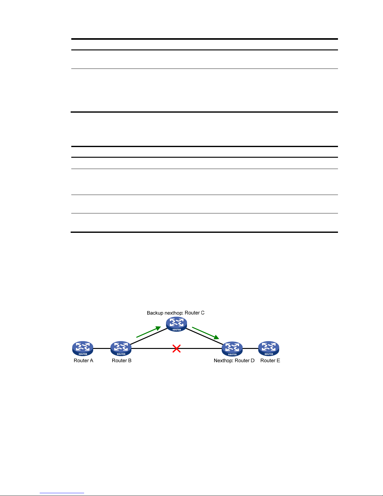
78
Step Command
Remarks
2. Enter interface view.
interface interface-type
interface-number
N/A
3. Enable BFD bidirectional control
detection.
ospf bfd enable
By default, BFD bidirectional
control detection is disabled.
Both ends of a BFD session must be
on the same network segment and
in the same area.
Configuring single-hop echo detection
Step Command
Remarks
1. Enter system view.
system-view N/A
2. Configure the source address of echo
packets.
bfd echo-source-ip ip-address
By default, the source
address of echo packets is
not configured.
3. Enter interface view.
interface interface-type
interface-number
N/A
4. Enable BFD single-hop echo
detection.
ospf bfd enable echo
By default, BFD single-hop
echo detection is disabled.
Configuring OSPF FRR
A link or router failure on a path can cause packet loss and even routing loop until OSPF completes
routing convergence based on the new network topology. FRR uses BFD to detect failures and enables
fast rerouting to minimize the impact of link or node failures.
Figure 19 Network diagram for OSPF FRR
In Figure 19, configure FRR on Router B by using a routing policy to specify a backup next hop. When the
primary link fails, OSPF directs packets to the backup next hop. At the same time, OSPF calculates the
shortest path based on the new network topology, and forwards packets over the path after network
convergence.
You can configure OSPF FRR to calculate a backup next hop by using the loop free alternate (LFA)
algorithm, or specify a backup next hop by using a routing policy.
Page 90

79
Configuration prerequisites
Before you configure OSPF FRR, complete the following tasks:
• Configure IP addresses for interfaces to ensure IP connectivity between neighboring nodes.
• Enable OSPF.
Configuration guidelines
• Do not use FRR and BFD at the same time. Otherwise, FRR might fail to take effect.
• Do not use the fast-reroute lfa command together with the command vlink-peer.
Configuring OSPF FRR to calculate a backup next hop using the
LFA algorithm
Step Command
Remarks
1. Enter system view.
system-view N/A
2. Configure the source address
of echo packets.
bfd echo-source-ip ip-address
By default, the source address of echo
packets is not configured.
3. Enter interface view.
interface interface-type
interface-number
N/A
4. Enable LFA calculation on an
interface.
ospf fast-reroute lfa-backup
By default, the interface on which LFA
calculation is enabled can be selected
as a backup interface.
5. Return to system view.
quit N/A
6. Enter OSPF view.
ospf [ process-id | router-id
router-id | vpn-instance
vpn-instance-name ] *
N/A
7. Enable OSPF FRR to calculate
a backup next hop by using
the LFA algorithm.
fast-reroute lfa [ abr-only ]
By default, OSPF FRR is n o t c onfigured.
If abr-only is specified, the route to the
ABR is selected as the backup path.
Configuring OSPF FRR to specify a backup next hop using a
routing policy
Before you configure this task, use the apply fast-reroute backup-interface command to specify a backup
next hop in the routing policy to be referenced. For more information about the apply fast-reroute
backup-interface command and routing policy configuration, see "Configuring routing policies."
To configure OSPF FRR to specify a backup next hop using a routing policy:
Step Command
Remarks
1. Enter system view.
system-view N/A
Page 91

80
Step Command
Remarks
2. Configure the source address
of echo packets.
bfd echo-source-ip ip-address
By default, the source address of
echo packets is not configured.
3. Enter OSPF view.
ospf [ process-id | router-id
router-id | vpn-instance
vpn-instance-name ] *
N/A
4. Enable OSPF FRR to specify a
backup next hop by using a
routing policy.
fast-reroute route-policy
route-policy-name
By default, OSPF FRR is not
configured.
Displaying and maintaining OSPF
Execute display commands in any view and reset commands in user view.
Task Command
Display OSPF brief information.
display ospf [ process-id ] brief
Display OSPF statistics.
display ospf [ process-id ] cumulative
Display GR status of the specified
OSPF process.
display ospf [ process-id ] graceful-restart [ verbose ]
Display Link State Database
information.
display ospf [ process-id ] lsdb [ brief | [ { ase | router | network |
summary | asbr | nssa | opaque-link | opaque-area | opaque-as }
[ link-state-id ] ] [ originate-router advertising-router-id | self-originate ] ]
Display OSPF neighbor
information.
display ospf [ process-id ] peer [ verbose ] [ interface-type
interface-number ] [ neighbor-id ]
Display neighbor statistics for
OSPF areas.
display ospf [ process-id ] peer statistics
Display routing table information.
display ospf [ process-id ] routing [ interface interface-type
interface-number ] [ nexthop nexthop-address ] [ verbose ]
Display virtual link information.
display ospf [ process-id ] vlink
Display OSPF request queue
information.
display ospf [ process-id ] request-queue [ interface-type
interface-number ] [ neighbor-id ]
Display OSPF retransmission
queue information.
display ospf [ process-id ] retrans-queue [ interface-type
interface-number ] [ neighbor-id ]
Display OSPF ABR and ASBR
information.
display ospf [ process-id ] abr-asbr
Display OSPF interface
information.
display ospf [ process-id ] interface [ all | interface-type
interface-number ]
Display OSPF error information.
display ospf [ process-id ] error
Display OSPF ASBR route
summarization information.
display ospf [ process-id ] asbr-summary [ ip-address { mask |
mask-length } ]
Display the global route ID. display router id
Clear OSPF statistics. reset ospf [ process-id ] counters
Reset an OSPF process. reset ospf [ process-id ] process [ graceful-restart ]
Page 92

81
Task Command
Re-enable OSPF route
redistribution.
reset ospf [ process-id ] redistribution
OSPF configuration examples
These configuration examples only cover commands for OSPF configuration.
Configuring basic OSPF
Network requirements
• Enable OSPF on all switches, and split the AS into three areas.
• Configure Switch A and Switch B as ABRs.
Figure 20 Network diagram
Configuration procedure
1. Configure IP addresses for interfaces. (Details not shown.)
2. Enable OSPF:
# Configure Switch A.
<SwitchA> system-view
[SwitchA] router id 10.2.1.1
[SwitchA] ospf
[SwitchA-ospf-1] area 0
[SwitchA-ospf-1-area-0.0.0.0] network 10.1.1.0 0.0.0.255
[SwitchA-ospf-1-area-0.0.0.0] quit
[SwitchA-ospf-1] area 1
[SwitchA-ospf-1-area-0.0.0.1] network 10.2.1.0 0.0.0.255
[SwitchA-ospf-1-area-0.0.0.1] quit
[SwitchA-ospf-1] quit
# Configure Switch B.
<SwitchB> system-view
[SwitchB] router id 10.3.1.1
[SwitchB] ospf
Area 0
Area 1
Area 2
Switch C
Vlan-int100
10.1.1.2/24
Vlan-int100
10.1.1.1/24
Vlan-int300
10.4.1.1/24
Vlan-int200
10.2.1.2/24
Switch B
Vlan-int200
10.3.1.1/24
Vlan-int200
10.3.1.2/24
Switch A
Vlan-int200
10.2.1.1/24
Vlan-int300
10.5.1.1/24
Switch D
Page 93

82
[SwitchB-ospf-1] area 0
[SwitchB-ospf-1-area-0.0.0.0] network 10.1.1.0 0.0.0.255
[SwitchB-ospf-1-area-0.0.0.0] quit
[SwitchB-ospf-1] area 2
[SwitchB-ospf-1-area-0.0.0.2] network 10.3.1.0 0.0.0.255
[SwitchB-ospf-1-area-0.0.0.2] quit
[SwitchB-ospf-1] quit
# Configure Switch C.
<SwitchC> system-view
[SwitchC] router id 10.4.1.1
[SwitchC] ospf
[SwitchC-ospf-1] area 1
[SwitchC-ospf-1-area-0.0.0.1] network 10.2.1.0 0.0.0.255
[SwitchC-ospf-1-area-0.0.0.1] network 10.4.1.0 0.0.0.255
[SwitchC-ospf-1-area-0.0.0.1] quit
[SwitchC-ospf-1] quit
# Configure Switch D.
<SwitchD> system-view
[SwitchD] router id 10.5.1.1
[SwitchD] ospf
[SwitchD-ospf-1] area 2
[SwitchD-ospf-1-area-0.0.0.2] network 10.3.1.0 0.0.0.255
[SwitchD-ospf-1-area-0.0.0.2] network 10.5.1.0 0.0.0.255
[SwitchD-ospf-1-area-0.0.0.2] quit
[SwitchD-ospf-1] quit
Verifying the configuration
# Display information about neighbors on Switch A.
[SwitchA] display ospf peer verbose
OSPF Process 1 with Router ID 10.2.1.1
Neighbors
Area 0.0.0.0 interface 10.1.1.1(Vlan-interface100)'s neighbors
Router ID: 10.3.1.1 Address: 10.1.1.2 GR State: Normal
State: Full Mode: Nbr is Master Priority: 1
DR: 10.1.1.1 BDR: 10.1.1.2 MTU: 0
Options is 0x02 (-|-|-|-|-|-|E|-)
Dead timer due in 37 sec
Neighbor is up for 06:03:59
Authentication Sequence: [ 0 ]
Neighbor state change count: 5
Neighbors
Area 0.0.0.1 interface 10.2.1.1(Vlan-interface200)'s neighbors
Router ID: 10.4.1.1 Address: 10.2.1.2 GR State: Normal
State: Full Mode: Nbr is Master Priority: 1
Page 94

83
DR: 10.2.1.1 BDR: 10.2.1.2 MTU: 0
Options is 0x02 (-|-|-|-|-|-|E|-)
Dead timer due in 32 sec
Neighbor is up for 06:03:12
Authentication Sequence: [ 0 ]
Neighbor state change count: 5
# Display OSPF routing information on Switch A.
[SwitchA] display ospf routing
OSPF Process 1 with Router ID 10.2.1.1
Routing Tables
Routing for Network
Destination Cost Type NextHop AdvRouter Area
10.2.1.0/24 1 Transit 10.2.1.1 10.2.1.1 0.0.0.1
10.3.1.0/24 2 Inter 10.1.1.2 10.3.1.1 0.0.0.0
10.4.1.0/24 2 Stub 10.2.1.2 10.4.1.1 0.0.0.1
10.5.1.0/24 3 Inter 10.1.1.2 10.3.1.1 0.0.0.0
10.1.1.0/24 1 Transit 10.1.1.1 10.2.1.1 0.0.0.0
Total Nets: 5
Intra Area: 3 Inter Area: 2 ASE: 0 NSSA: 0
# Display OSPF routing information on Switch D.
[SwitchD] display ospf routing
OSPF Process 1 with Router ID 10.5.1.1
Routing Tables
Routing for Network
Destination Cost Type NextHop AdvRouter Area
10.2.1.0/24 3 Inter 10.3.1.1 10.3.1.1 0.0.0.2
10.3.1.0/24 1 Transit 10.3.1.2 10.3.1.1 0.0.0.2
10.4.1.0/24 4 Inter 10.3.1.1 10.3.1.1 0.0.0.2
10.5.1.0/24 1 Stub 10.5.1.1 10.5.1.1 0.0.0.2
10.1.1.0/24 2 Inter 10.3.1.1 10.3.1.1 0.0.0.2
Total Nets: 5
Intra Area: 2 Inter Area: 3 ASE: 0 NSSA: 0
# On Switch D, ping the IP address 10.4.1.1 to test reachability.
[SwitchD] ping 10.4.1.1
PING 10.4.1.1: 56 data bytes, press CTRL_C to break
Reply from 10.4.1.1: bytes=56 Sequence=2 ttl=253 time=2 ms
Reply from 10.4.1.1: bytes=56 Sequence=2 ttl=253 time=1 ms
Reply from 10.4.1.1: bytes=56 Sequence=3 ttl=253 time=1 ms
Reply from 10.4.1.1: bytes=56 Sequence=4 ttl=253 time=1 ms
Reply from 10.4.1.1: bytes=56 Sequence=5 ttl=253 time=1 ms
Page 95

84
--- 10.4.1.1 ping statistics -- 5 packet(s) transmitted
5 packet(s) received
0.00% packet loss
round-trip min/avg/max = 1/1/2 ms
Configuring OSPF route redistribution
Network requirements
• Enable OSPF on all the switches.
• Split the AS into three areas.
• Configure Switch A and Switch B as ABRs.
• Configure Switch C as an ASBR to redistribute external routes (static routes).
Figure 21 Network diagram
Configuration procedure
1. Configure IP addresses for interfaces. (Details not shown.)
2. Enable OSPF (see "Configuring basic OSPF").
3. Config
ure OSPF to redistribute routes:
# On Switch C, configure a static route destined for network 3.1.2.0/24.
<SwitchC> system-view
[SwitchC] ip route-static 3.1.2.1 24 10.4.1.2
# On Switch C, configure OSPF to redistribute static routes.
[SwitchC] ospf 1
[SwitchC-ospf-1] import-route static
Verifying the configuration
# Display the ABR/ASBR information of Switch D.
<SwitchD> display ospf abr-asbr
OSPF Process 1 with Router ID 10.5.1.1
Routing Table to ABR and ASBR
Type Destination Area Cost Nexthop RtType
Intra 10.3.1.1 0.0.0.2 10 10.3.1.1 ABR
Page 96

85
Inter 10.4.1.1 0.0.0.2 22 10.3.1.1 ASBR
# Display the OSPF routing table on Switch D.
<SwitchD> display ospf routing
OSPF Process 1 with Router ID 10.5.1.1
Routing Tables
Routing for Network
Destination Cost Type NextHop AdvRouter Area
10.2.1.0/24 22 Inter 10.3.1.1 10.3.1.1 0.0.0.2
10.3.1.0/24 10 Transit 10.3.1.2 10.3.1.1 0.0.0.2
10.4.1.0/24 25 Inter 10.3.1.1 10.3.1.1 0.0.0.2
10.5.1.0/24 10 Stub 10.5.1.1 10.5.1.1 0.0.0.2
10.1.1.0/24 12 Inter 10.3.1.1 10.3.1.1 0.0.0.2
Routing for ASEs
Destination Cost Type Tag NextHop AdvRouter
3.1.2.0/24 1 Type2 1 10.3.1.1 10.4.1.1
Total Nets: 6
Intra Area: 2 Inter Area: 3 ASE: 1 NSSA: 0
Configuring OSPF to advertise a summary route
Network requirements
• Configure OSPF on Switch A and Switch B in AS 200.
• Configure OSPF on Switch C, Switch D, and Switch E in AS 100.
• Configure an EBGP connection between Switch B and Switch C. Configure Switch B and Switch C
to redistribute OSPF routes and direct routes into BGP and BGP routes into OSPF.
• Configure Switch B to advertise only summary route 10.0.0.0/8 to Switch A.
Page 97
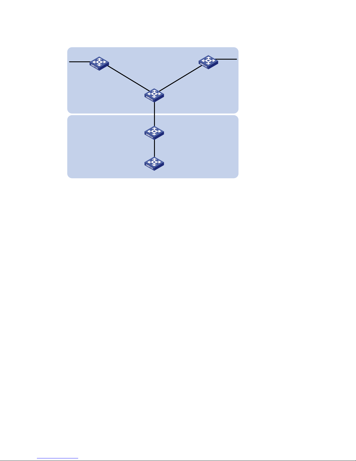
86
Figure 22 Network diagram
Configuration procedure
1. Configure IP addresses for interfaces. (Details not shown.)
2. Enable OSPF:
# Configure Switch A.
<SwitchA> system-view
[SwitchA] router id 11.2.1.2
[SwitchA] ospf
[SwitchA-ospf-1] area 0
[SwitchA-ospf-1-area-0.0.0.0] network 11.2.1.0 0.0.0.255
[SwitchA-ospf-1-area-0.0.0.0] quit
[SwitchA-ospf-1] quit
# Configure Switch B.
<SwitchB> system-view
[SwitchB] router id 11.2.1.1
[SwitchB] ospf
[SwitchB-ospf-1] area 0
[SwitchB-ospf-1-area-0.0.0.0] network 11.2.1.0 0.0.0.255
[SwitchB-ospf-1-area-0.0.0.0] quit
[SwitchB-ospf-1] quit
# Configure Switch C.
<SwitchC> system-view
[SwitchC] router id 11.1.1.2
[SwitchC] ospf
[SwitchC-ospf-1] area 0
[SwitchC-ospf-1-area-0.0.0.0] network 10.1.1.0 0.0.0.255
[SwitchC-ospf-1-area-0.0.0.0] network 10.2.1.0 0.0.0.255
[SwitchC-ospf-1-area-0.0.0.0] quit
[SwitchC-ospf-1] quit
Switch A
Switch B
Switch D
Switch E
Switch C
Vlan-int400
10.1.1.1/24
Vlan-int400
10.1.1.2/24
Vlan-int300
10.2.1.2/24
Vlan-int300
10.2.1.1/24
Vlan-int200
11.1.1.2/24
Vlan-int200
11.1.1.1/24
EBGP
AS 200
AS 100
Vlan-int100
11.2.1.1/24
Vlan-int100
11.2.1.2/24
Vlan-int500
10.3.1.1/24
Vlan-int600
10.4.1.1/24
Page 98

87
# Configure Switch D.
<SwitchD> system-view
[SwitchD] router id 10.3.1.1
[SwitchD] ospf
[SwitchD-ospf-1] area 0
[SwitchD-ospf-1-area-0.0.0.0] network 10.1.1.0 0.0.0.255
[SwitchD-ospf-1-area-0.0.0.0] network 10.3.1.0 0.0.0.255
[SwitchD-ospf-1-area-0.0.0.0] quit
# Configure Switch E.
<SwitchE> system-view
[SwitchE] router id 10.4.1.1
[SwitchE] ospf
[SwitchE-ospf-1] area 0
[SwitchE-ospf-1-area-0.0.0.0] network 10.2.1.0 0.0.0.255
[SwitchE-ospf-1-area-0.0.0.0] network 10.4.1.0 0.0.0.255
[SwitchE-ospf-1-area-0.0.0.0] quit
[SwitchE-ospf-1] quit
3. Configure BGP to redistribute OSPF routes and direct routes:
# Configure Switch B.
[SwitchB] bgp 200
[SwitchB-bgp] peer 11.1.1.2 as 100
[SwitchB-bgp] ipv4-family unicast
[SwitchB-bgp-ipv4] import-route ospf
[SwitchB-bgp-ipv4] import-route direct
[SwitchB-bgp ipv4] quit
[SwitchB-bgp] quit
# Configure Switch C.
[SwitchC] bgp 100
[SwitchC-bgp] peer 11.1.1.1 as 200
[SwitchC-bgp] ipv4-family unicast
[SwitchC-bgp-ipv4] import-route ospf
[SwitchC-bgp-ipv4]import-route direct
[SwitchC-bgp-ipv4] quit
[SwitchC-bgp] quit
4. Configure Switch B and Switch C to redistribute BGP routes into OSPF:
# Configure OSPF to redistribute routes from BGP on Switch B.
[SwitchB] ospf
[SwitchB-ospf-1] import-route bgp
# Configure OSPF to redistribute routes from BGP on Switch C.
[SwitchC] ospf
[SwitchC-ospf-1] import-route bgp
# Display the OSPF routing table on Switch A.
[SwitchA] display ip routing-table
Destinations : 16 Routes : 16
Destination/Mask Proto Pre Cost NextHop Interface
Page 99

88
0.0.0.0/32 Direct 0 0 127.0.0.1 InLoop0
10.1.1.0/24 OSPF 150 1 11.2.1.1 Vlan100
10.2.1.0/24 OSPF 150 1 11.2.1.1 Vlan100
10.3.1.0/24 OSPF 150 1 11.2.1.1 Vlan100
10.4.1.0/24 OSPF 150 1 11.2.1.1 Vlan100
11.2.1.0/24 Direct 0 0 11.2.1.2 Vlan100
11.2.1.0/32 Direct 0 0 11.2.1.2 Vlan100
11.2.1.2/32 Direct 0 0 127.0.0.1 InLoop0
11.2.1.255/32 Direct 0 0 11.2.1.2 Vlan100
127.0.0.0/8 Direct 0 0 127.0.0.1 InLoop0
127.0.0.0/32 Direct 0 0 127.0.0.1 InLoop0
127.0.0.1/32 Direct 0 0 127.0.0.1 InLoop0
127.255.255.255/32 Direct 0 0 127.0.0.1 InLoop0
224.0.0.0/4 Direct 0 0 0.0.0.0 NULL0
224.0.0.0/24 Direct 0 0 0.0.0.0 NULL0
255.255.255.255/32 Direct 0 0 127.0.0.1 InLoop0
5. Configure route summarization:
# Configure route summarization on Switch B to advertise a summary route 10.0.0.0/8.
[SwitchB-ospf-1] asbr-summary 10.0.0.0 8
# Display the IP routing table on Switch A.
[SwitchA] display ip routing-table
Destinations : 13 Routes : 13
Destination/Mask Proto Pre Cost NextHop Interface
0.0.0.0/32 Direct 0 0 127.0.0.1 InLoop0
10.0.0.0/8 OSPF 150 2 11.2.1.1 Vlan100
11.2.1.0/24 Direct 0 0 11.2.1.2 Vlan100
11.2.1.0/32 Direct 0 0 11.2.1.2 Vlan100
11.2.1.2/32 Direct 0 0 127.0.0.1 InLoop0
11.2.1.255/32 Direct 0 0 11.2.1.2 Vlan100
127.0.0.0/8 Direct 0 0 127.0.0.1 InLoop0
127.0.0.0/32 Direct 0 0 127.0.0.1 InLoop0
127.0.0.1/32 Direct 0 0 127.0.0.1 InLoop0
127.255.255.255/32 Direct 0 0 127.0.0.1 InLoop0
224.0.0.0/4 Direct 0 0 0.0.0.0 NULL0
224.0.0.0/24 Direct 0 0 0.0.0.0 NULL0
255.255.255.255/32 Direct 0 0 127.0.0.1 InLoop0
The output shows that routes 10.1.1.0/24, 10.2.1.0/24, 10.3.1.0/24 and 10.4.1.0/24 are
summarized into a single route 10.0.0.0/8.
Configuring an OSPF stub area
Network requirements
• Enable OSPF on all switches, and split the AS into three areas.
• Configure Switch A and Switch B as ABRs to forward routing information between areas.
Page 100

89
• Configure Switch D as the ASBR to redistribute static routes.
• Configure Area 1 as a stub area to reduce advertised LSAs without influencing reachability.
Figure 23 Network diagram
Configuration procedure
1. Configure IP addresses for interfaces. (Details not shown.)
2. Enable OSPF (see "Configuring basic OSPF").
3. Config
ure route redistribution:
# Configure Switch D to redistribute static routes.
<SwitchD> system-view
[SwitchD] ip route-static 3.1.2.1 24 10.5.1.2
[SwitchD] ospf
[SwitchD-ospf-1] import-route static
[SwitchD-ospf-1] quit
# Display ABR/ASBR information on Switch C.
<SwitchC> display ospf abr-asbr
OSPF Process 1 with Router ID 10.4.1.1
Routing Table to ABR and ASBR
Type Destination Area Cost Nexthop RtType
Intra 10.2.1.1 0.0.0.1 3 10.2.1.1 ABR
Inter 10.5.1.1 0.0.0.1 7 10.2.1.1 ASBR
# Display OSPF routing table on Switch C.
<SwitchC> display ospf routing
OSPF Process 1 with Router ID 10.4.1.1
Routing Tables
Routing for Network
Destination Cost Type NextHop AdvRouter Area
10.2.1.0/24 3 Transit 10.2.1.2 10.2.1.1 0.0.0.1
10.3.1.0/24 7 Inter 10.2.1.1 10.2.1.1 0.0.0.1
10.4.1.0/24 3 Stub 10.4.1.1 10.4.1.1 0.0.0.1
10.5.1.0/24 17 Inter 10.2.1.1 10.2.1.1 0.0.0.1
Area 0
Area 1
Stub
Area 2
Switch C
Vlan-int100
10.1.1.2/24
Vlan-int100
10.1.1.1/24
Vlan-int300
10.4.1.1/24
Vlan-int200
10.2.1.2/24
Switch B
Vlan-int200
10.3.1.1/24
Vlan-int200
10.3.1.2/24
Switch A
Vlan-int200
10.2.1.1/24
Vlan-int300
10.5.1.1/24
Switch D
ASBR
 Loading...