

Page 1

HP ProBook 5320m Notebook PC
Maintenance and Service Guide
Document Part Number: 609313-002, Rev. D
February 2012
This guide is a troubleshooting reference used for maintaining and servicing the computer. It provides
comprehensive information on identifying computer features, components, and spare parts; troubleshooting
computer problems; and performing computer disassembly procedures.
Page 2

Addendum Revision History
Part Number Publication Date Description
-002 (Rev. A) July 2010 ■ Corrected the descriptions for system boards 593840-001 and 593841-001.
-002 (Rev. B) October 2010 ■ Corrected the descriptions for system boards 593840-001 and 593841-001.
-002 (Rev. C) February 2011 ■ Corrected the descriptions for the Intel Core i3 350M and Intel Core i3 330M
-002 (Rev. D) February 2012 Deleted the following obselete spare part numbers:
■ Correct the HP Compaq 6440b Cable Kit spare part number to 593854-001.
■ Added new displays and WLAN modules to the Product Description table.
■ Add new display panel spare part numbers.
■ Added new and updated existing hard drive spare part numbers.
■ Added a new system board spare part number.
■ Updated memory module part numbers for all models.
■ Added new WLAN module spare part numbers.
■ Added new AC adapter spare part numbers.
■ Added a spare part number for an upgrade bay.
processors and spare part numbers 595586-001 and 595587-001.
■ 581096-001 – 2-GB memory module
■ 598859-001 – 1-GB memory module
■ 613152-001 – 65-W RC/V AC adapter
■ 613161-001 – 65-W RC/V/EMI AC adapter
Added the following new spare part numbers:
■ 581094-001 – Hinge Bracket Kit
■ 609939-001 – 65-W RC/V AC adapter
■ 609948-001 – 65-W RC/V/EMI AC adapter
■ 621565-001 – 2-GB memory module
■ 623161-001 – AntiGlare display panel
■ 623185-001 – BrightView display panel
■ 631048-001 – i3-380M 2.53-GHz system board
■ 631049-001 – i3-380M 2.53-GHz system board for use in Russia and China
■ 631050-001 – i5-460M 2.53-GHz system board
■ 631051-001 – i5-460M 2.53-GHz system board for use in Russia and China
■ 642739-001 – i5-460M 2.66-GHz system board
■ 642740-001 – i5-460M 2.66-GHz system board for use in Russia and China
Page 3

© Copyright 2012 Hewlett-Packard Development Company, L.P.
AMD Athlon, AMD Sempron, and AMD Turion are trademarks of Advanced Micro Devices, Inc. Bluetooth is a trademark owned by its
proprietor and used by Hewlett-Packard Company under license. Intel and Core are U.S. registered trademarks of Intel Corporation.
Java is a U.S. trademark of Sun Microsystems, Inc. Microsoft, Windows, and Windows Vista are U.S. registered trademarks of
Microsoft Corporation. SD Logo is a trademark of its proprietor.
The information contained herein is subject to change without notice. The only warranties for HP products and services are set forth in
the express warranty statements accompanying such products and services. Nothing herein should be construed as constituting an
additional warranty. HP shall not be liable for technical or editorial errors or omissions contained herein.
Second Edition: February 2011
Document Part Number: 570786-002, Rev. D
Page 4

Safety warning notice
WARNING: To reduce the possibility of heat-related injuries or of overheating the computer, do not place the computer directly
Å
on your lap or obstruct the computer air vents. Use the computer only on a hard, flat surface. Do not allow another hard surface,
such as an adjoining optional printer, or a soft surface, such as pillows or rugs or clothing, to block airflow. Also, do not allow
the AC adapter to contact the skin or a soft surface, such as pillows or rugs or clothing, during operation. The computer and the
AC adapter comply with the user-accessible surface temperature limits defined by the International Standard for Safety of
Information Technology Equipment (IEC 60950).
Page 5

Contents
1 Product description
2 External component identification
Identifying hardware . . . . . . . . . . . . . . . . . . . . . . . . . . . . . . . . . . . . . . . . . . . . . . . . . . . . . . . . . . . . . . . . . . 2–1
Top components. . . . . . . . . . . . . . . . . . . . . . . . . . . . . . . . . . . . . . . . . . . . . . . . . . . . . . . . . . . . . . . . . . . . . . 2–2
Display components . . . . . . . . . . . . . . . . . . . . . . . . . . . . . . . . . . . . . . . . . . . . . . . . . . . . . . . . . . . . . . . 2–2
Wireless antennas (select models only) . . . . . . . . . . . . . . . . . . . . . . . . . . . . . . . . . . . . . . . . . . . . . . . . 2–3
Buttons . . . . . . . . . . . . . . . . . . . . . . . . . . . . . . . . . . . . . . . . . . . . . . . . . . . . . . . . . . . . . . . . . . . . . . . . . 2–4
Keys . . . . . . . . . . . . . . . . . . . . . . . . . . . . . . . . . . . . . . . . . . . . . . . . . . . . . . . . . . . . . . . . . . . . . . . . . . . 2–5
Lights . . . . . . . . . . . . . . . . . . . . . . . . . . . . . . . . . . . . . . . . . . . . . . . . . . . . . . . . . . . . . . . . . . . . . . . . . . 2–6
Pointing devices . . . . . . . . . . . . . . . . . . . . . . . . . . . . . . . . . . . . . . . . . . . . . . . . . . . . . . . . . . . . . . . . . . 2–7
Front components. . . . . . . . . . . . . . . . . . . . . . . . . . . . . . . . . . . . . . . . . . . . . . . . . . . . . . . . . . . . . . . . . . . . . 2–8
Right-side components. . . . . . . . . . . . . . . . . . . . . . . . . . . . . . . . . . . . . . . . . . . . . . . . . . . . . . . . . . . . . . . . . 2–8
Left-side components . . . . . . . . . . . . . . . . . . . . . . . . . . . . . . . . . . . . . . . . . . . . . . . . . . . . . . . . . . . . . . . . . . 2–9
Bottom components . . . . . . . . . . . . . . . . . . . . . . . . . . . . . . . . . . . . . . . . . . . . . . . . . . . . . . . . . . . . . . . . . . 2–10
3 Illustrated parts catalog
Serial number label location. . . . . . . . . . . . . . . . . . . . . . . . . . . . . . . . . . . . . . . . . . . . . . . . . . . . . . . . . . . . . 3–1
Computer major components . . . . . . . . . . . . . . . . . . . . . . . . . . . . . . . . . . . . . . . . . . . . . . . . . . . . . . . . . . . . 3–2
Cable Kit . . . . . . . . . . . . . . . . . . . . . . . . . . . . . . . . . . . . . . . . . . . . . . . . . . . . . . . . . . . . . . . . . . . . . . . . . . . 3–6
Display assembly subcomponents . . . . . . . . . . . . . . . . . . . . . . . . . . . . . . . . . . . . . . . . . . . . . . . . . . . . . . . . 3–7
Mass storage devices . . . . . . . . . . . . . . . . . . . . . . . . . . . . . . . . . . . . . . . . . . . . . . . . . . . . . . . . . . . . . . . . . . 3–8
Plastics Kit . . . . . . . . . . . . . . . . . . . . . . . . . . . . . . . . . . . . . . . . . . . . . . . . . . . . . . . . . . . . . . . . . . . . . . . . . . 3–9
Miscellaneous parts . . . . . . . . . . . . . . . . . . . . . . . . . . . . . . . . . . . . . . . . . . . . . . . . . . . . . . . . . . . . . . . . . . 3–10
Sequential part number listing . . . . . . . . . . . . . . . . . . . . . . . . . . . . . . . . . . . . . . . . . . . . . . . . . . . . . . . . . . 3–11
4 Removal and replacement procedures
Preliminary replacement requirements . . . . . . . . . . . . . . . . . . . . . . . . . . . . . . . . . . . . . . . . . . . . . . . . . . . . 4–1
Tools required . . . . . . . . . . . . . . . . . . . . . . . . . . . . . . . . . . . . . . . . . . . . . . . . . . . . . . . . . . . . . . . . . . . . 4–1
Service considerations. . . . . . . . . . . . . . . . . . . . . . . . . . . . . . . . . . . . . . . . . . . . . . . . . . . . . . . . . . . . . . 4–1
Grounding guidelines . . . . . . . . . . . . . . . . . . . . . . . . . . . . . . . . . . . . . . . . . . . . . . . . . . . . . . . . . . . . . . 4–2
Component replacement procedures . . . . . . . . . . . . . . . . . . . . . . . . . . . . . . . . . . . . . . . . . . . . . . . . . . . . . . 4–5
Serial number location . . . . . . . . . . . . . . . . . . . . . . . . . . . . . . . . . . . . . . . . . . . . . . . . . . . . . . . . . . . . . 4–5
Computer feet . . . . . . . . . . . . . . . . . . . . . . . . . . . . . . . . . . . . . . . . . . . . . . . . . . . . . . . . . . . . . . . . . . . . 4–6
Battery. . . . . . . . . . . . . . . . . . . . . . . . . . . . . . . . . . . . . . . . . . . . . . . . . . . . . . . . . . . . . . . . . . . . . . . . . . 4–7
SIM . . . . . . . . . . . . . . . . . . . . . . . . . . . . . . . . . . . . . . . . . . . . . . . . . . . . . . . . . . . . . . . . . . . . . . . . . . . . 4–8
Mass storage device . . . . . . . . . . . . . . . . . . . . . . . . . . . . . . . . . . . . . . . . . . . . . . . . . . . . . . . . . . . . . . . 4–9
Bluetooth module . . . . . . . . . . . . . . . . . . . . . . . . . . . . . . . . . . . . . . . . . . . . . . . . . . . . . . . . . . . . . . . . 4–12
WLAN module . . . . . . . . . . . . . . . . . . . . . . . . . . . . . . . . . . . . . . . . . . . . . . . . . . . . . . . . . . . . . . . . . . 4–14
WWAN module . . . . . . . . . . . . . . . . . . . . . . . . . . . . . . . . . . . . . . . . . . . . . . . . . . . . . . . . . . . . . . . . . 4–17
RTC battery. . . . . . . . . . . . . . . . . . . . . . . . . . . . . . . . . . . . . . . . . . . . . . . . . . . . . . . . . . . . . . . . . . . . . 4–20
Memory module . . . . . . . . . . . . . . . . . . . . . . . . . . . . . . . . . . . . . . . . . . . . . . . . . . . . . . . . . . . . . . . . . 4–21
Maintenance and Service Guide iv
Page 6

Contents
Keyboard. . . . . . . . . . . . . . . . . . . . . . . . . . . . . . . . . . . . . . . . . . . . . . . . . . . . . . . . . . . . . . . . . . . . . . . 4–23
Button board and cable . . . . . . . . . . . . . . . . . . . . . . . . . . . . . . . . . . . . . . . . . . . . . . . . . . . . . . . . . . . . 4–26
Top cover . . . . . . . . . . . . . . . . . . . . . . . . . . . . . . . . . . . . . . . . . . . . . . . . . . . . . . . . . . . . . . . . . . . . . . 4–28
Power button board and cable. . . . . . . . . . . . . . . . . . . . . . . . . . . . . . . . . . . . . . . . . . . . . . . . . . . . . . . 4–31
Bluetooth module cable . . . . . . . . . . . . . . . . . . . . . . . . . . . . . . . . . . . . . . . . . . . . . . . . . . . . . . . . . . . 4–32
System board. . . . . . . . . . . . . . . . . . . . . . . . . . . . . . . . . . . . . . . . . . . . . . . . . . . . . . . . . . . . . . . . . . . . 4–33
Fan and heat sink. . . . . . . . . . . . . . . . . . . . . . . . . . . . . . . . . . . . . . . . . . . . . . . . . . . . . . . . . . . . . . . . . 4–36
Speaker assembly . . . . . . . . . . . . . . . . . . . . . . . . . . . . . . . . . . . . . . . . . . . . . . . . . . . . . . . . . . . . . . . . 4–39
USB board. . . . . . . . . . . . . . . . . . . . . . . . . . . . . . . . . . . . . . . . . . . . . . . . . . . . . . . . . . . . . . . . . . . . . . 4–40
Battery eject arm . . . . . . . . . . . . . . . . . . . . . . . . . . . . . . . . . . . . . . . . . . . . . . . . . . . . . . . . . . . . . . . . . 4–41
Display assembly . . . . . . . . . . . . . . . . . . . . . . . . . . . . . . . . . . . . . . . . . . . . . . . . . . . . . . . . . . . . . . . . 4–43
5 Computer Setup
Computer Setup in Windows 7 . . . . . . . . . . . . . . . . . . . . . . . . . . . . . . . . . . . . . . . . . . . . . . . . . . . . . . . . . . 5–1
Starting Computer Setup. . . . . . . . . . . . . . . . . . . . . . . . . . . . . . . . . . . . . . . . . . . . . . . . . . . . . . . . . . . . 5–1
Using Computer Setup . . . . . . . . . . . . . . . . . . . . . . . . . . . . . . . . . . . . . . . . . . . . . . . . . . . . . . . . . . . . . 5–1
Computer Setup menus . . . . . . . . . . . . . . . . . . . . . . . . . . . . . . . . . . . . . . . . . . . . . . . . . . . . . . . . . . . . . . . . 5–3
File menu. . . . . . . . . . . . . . . . . . . . . . . . . . . . . . . . . . . . . . . . . . . . . . . . . . . . . . . . . . . . . . . . . . . . . . . . 5–3
Security menu . . . . . . . . . . . . . . . . . . . . . . . . . . . . . . . . . . . . . . . . . . . . . . . . . . . . . . . . . . . . . . . . . . . . 5–3
Diagnostics menu . . . . . . . . . . . . . . . . . . . . . . . . . . . . . . . . . . . . . . . . . . . . . . . . . . . . . . . . . . . . . . . . . 5–4
System Configuration menu . . . . . . . . . . . . . . . . . . . . . . . . . . . . . . . . . . . . . . . . . . . . . . . . . . . . . . . . . 5–5
Computer Setup in Windows Vista . . . . . . . . . . . . . . . . . . . . . . . . . . . . . . . . . . . . . . . . . . . . . . . . . . . . . . . 5–7
Starting Computer Setup. . . . . . . . . . . . . . . . . . . . . . . . . . . . . . . . . . . . . . . . . . . . . . . . . . . . . . . . . . . . 5–7
Using Computer Setup . . . . . . . . . . . . . . . . . . . . . . . . . . . . . . . . . . . . . . . . . . . . . . . . . . . . . . . . . . . . . 5–7
Computer Setup menus . . . . . . . . . . . . . . . . . . . . . . . . . . . . . . . . . . . . . . . . . . . . . . . . . . . . . . . . . . . . . . . . 5–8
File menu. . . . . . . . . . . . . . . . . . . . . . . . . . . . . . . . . . . . . . . . . . . . . . . . . . . . . . . . . . . . . . . . . . . . . . . . 5–8
Security menu . . . . . . . . . . . . . . . . . . . . . . . . . . . . . . . . . . . . . . . . . . . . . . . . . . . . . . . . . . . . . . . . . . . . 5–9
Diagnostics menu . . . . . . . . . . . . . . . . . . . . . . . . . . . . . . . . . . . . . . . . . . . . . . . . . . . . . . . . . . . . . . . . 5–10
System Configuration menu . . . . . . . . . . . . . . . . . . . . . . . . . . . . . . . . . . . . . . . . . . . . . . . . . . . . . . . . 5–10
Computer Setup in Windows XP . . . . . . . . . . . . . . . . . . . . . . . . . . . . . . . . . . . . . . . . . . . . . . . . . . . . . . . . 5–13
Starting Computer Setup. . . . . . . . . . . . . . . . . . . . . . . . . . . . . . . . . . . . . . . . . . . . . . . . . . . . . . . . . . . 5–13
Using Computer Setup . . . . . . . . . . . . . . . . . . . . . . . . . . . . . . . . . . . . . . . . . . . . . . . . . . . . . . . . . . . . 5–13
Computer Setup menus . . . . . . . . . . . . . . . . . . . . . . . . . . . . . . . . . . . . . . . . . . . . . . . . . . . . . . . . . . . . . . . 5–14
File menu. . . . . . . . . . . . . . . . . . . . . . . . . . . . . . . . . . . . . . . . . . . . . . . . . . . . . . . . . . . . . . . . . . . . . . . 5–14
Security menu . . . . . . . . . . . . . . . . . . . . . . . . . . . . . . . . . . . . . . . . . . . . . . . . . . . . . . . . . . . . . . . . . . . 5–15
Diagnostics menu . . . . . . . . . . . . . . . . . . . . . . . . . . . . . . . . . . . . . . . . . . . . . . . . . . . . . . . . . . . . . . . . 5–16
System Configuration menu . . . . . . . . . . . . . . . . . . . . . . . . . . . . . . . . . . . . . . . . . . . . . . . . . . . . . . . . 5–17
6 Specifications
Computer specifications. . . . . . . . . . . . . . . . . . . . . . . . . . . . . . . . . . . . . . . . . . . . . . . . . . . . . . . . . . . . . . . . 6–1
13.3-in display specifications. . . . . . . . . . . . . . . . . . . . . . . . . . . . . . . . . . . . . . . . . . . . . . . . . . . . . . . . . . . . 6–2
Hard drive specifications . . . . . . . . . . . . . . . . . . . . . . . . . . . . . . . . . . . . . . . . . . . . . . . . . . . . . . . . . . . . . . . 6–3
. . . . . . . . . . . . . . . . . . . . . . . . . . . . . . . . . . . . . . . . . . . . . . . . . . . . . . . . . . . . . . . . . . . . . . . . . . . . . . . . . . . 6–4
7 Backup and recovery
Backup and recovery in Windows 7 . . . . . . . . . . . . . . . . . . . . . . . . . . . . . . . . . . . . . . . . . . . . . . . . . . . . . . 8–1
Overview. . . . . . . . . . . . . . . . . . . . . . . . . . . . . . . . . . . . . . . . . . . . . . . . . . . . . . . . . . . . . . . . . . . . . . . . 8–1
Backing up your information . . . . . . . . . . . . . . . . . . . . . . . . . . . . . . . . . . . . . . . . . . . . . . . . . . . . . . . . 8–1
Performing a recovery. . . . . . . . . . . . . . . . . . . . . . . . . . . . . . . . . . . . . . . . . . . . . . . . . . . . . . . . . . . . . . 8–3
Backup and recovery in Windows Vista . . . . . . . . . . . . . . . . . . . . . . . . . . . . . . . . . . . . . . . . . . . . . . . . . . . 8–5
v Maintenance and Service Guide
Page 7

Overview. . . . . . . . . . . . . . . . . . . . . . . . . . . . . . . . . . . . . . . . . . . . . . . . . . . . . . . . . . . . . . . . . . . . . . . . 8–5
Backing up your information . . . . . . . . . . . . . . . . . . . . . . . . . . . . . . . . . . . . . . . . . . . . . . . . . . . . . . . . 8–5
Performing a recovery. . . . . . . . . . . . . . . . . . . . . . . . . . . . . . . . . . . . . . . . . . . . . . . . . . . . . . . . . . . . . . 8–6
Backup and recovery in Windows XP . . . . . . . . . . . . . . . . . . . . . . . . . . . . . . . . . . . . . . . . . . . . . . . . . . . . . 8–9
Overview. . . . . . . . . . . . . . . . . . . . . . . . . . . . . . . . . . . . . . . . . . . . . . . . . . . . . . . . . . . . . . . . . . . . . . . . 8–9
Backing up your information . . . . . . . . . . . . . . . . . . . . . . . . . . . . . . . . . . . . . . . . . . . . . . . . . . . . . . . . 8–9
Performing a recovery. . . . . . . . . . . . . . . . . . . . . . . . . . . . . . . . . . . . . . . . . . . . . . . . . . . . . . . . . . . . . 8–10
8 Connector pin assignments
Audio-in (microphone). . . . . . . . . . . . . . . . . . . . . . . . . . . . . . . . . . . . . . . . . . . . . . . . . . . . . . . . . . . . . . . . . 8–1
Audio-out (headphone) . . . . . . . . . . . . . . . . . . . . . . . . . . . . . . . . . . . . . . . . . . . . . . . . . . . . . . . . . . . . . . . . 8–1
External monitor. . . . . . . . . . . . . . . . . . . . . . . . . . . . . . . . . . . . . . . . . . . . . . . . . . . . . . . . . . . . . . . . . . . . . . 8–2
RJ-45 (network) . . . . . . . . . . . . . . . . . . . . . . . . . . . . . . . . . . . . . . . . . . . . . . . . . . . . . . . . . . . . . . . . . . . . . . 8–3
Universal Serial Bus. . . . . . . . . . . . . . . . . . . . . . . . . . . . . . . . . . . . . . . . . . . . . . . . . . . . . . . . . . . . . . . . . . . 8–4
9 Power cord set requirements
Requirements for all countries and regions . . . . . . . . . . . . . . . . . . . . . . . . . . . . . . . . . . . . . . . . . . . . . . . . . 9–1
Requirements for specific countries and regions . . . . . . . . . . . . . . . . . . . . . . . . . . . . . . . . . . . . . . . . . . . . . 9–2
Contents
10Recycling
Battery . . . . . . . . . . . . . . . . . . . . . . . . . . . . . . . . . . . . . . . . . . . . . . . . . . . . . . . . . . . . . . . . . . . . . . . . . . . . 10–1
Display . . . . . . . . . . . . . . . . . . . . . . . . . . . . . . . . . . . . . . . . . . . . . . . . . . . . . . . . . . . . . . . . . . . . . . . . . . . . 10–1
Index
Maintenance and Service Guide vi
Page 8

1
Product description
Category Description
Product name HP ProBook 5320m Notebook PC
Processors ■ Intel® Dual Core i5-45M 2.40-GHz processor (Turbo up to 2.53 GHz), 3-M L3 cache,
4 threads (35W)
■ Intel Dual Core i3-370M 2.40-GHz processor, 3-M L3 cache, 4 threads (35W)
■ Intel Dual Core i3-350M 2.26-GHz processor, 3-M L3 cache, 4 threads (35W)
■ Intel U3400 1.06-GHz processor
Chipset Intel HM57
Graphics Mobile Intel Graphics Media Accelerator HD unified memory architecture (UMA)
Panel ■ 13.3-in, high-definition (HD, 1366 × 768), AntiGlare, LED display assembly
■ 13.3-in, HD (1366 × 768), BrightView, LED display assembly
■ Supports privacy filter
Memory One customer-accessible/upgradable memory module slot
Supports the following DDR3 configurations at 1333 MHz in all countries and regions:
■ 4096-MB total system memory (4096 × 1)
■ 2048-MB total system memory (2048 × 1)
■ 1024-MB total system memory (1024 × 1) (not available on Microsoft 64-bit operating
systems)
Hard drives Supports 9.50-mm, 6.35-cm (2.50-in) hard drives
Customer-accessible
Supports the following hard drives:
■ 500-GB, 7200 rpm
■ 320-GB, 7200 rpm
■ 250-GB, 7200 rpm
Supports the following solid-state drives only with computer models running Windows 7
operating system, 2 GB or 4 GB:
■ 128-GB
■ 80-GB
Microphone Integrated dual-array digital microphone
Audio High-definition audio
Stereo speakers (2)
Webcam Integrated 2-megapixel camera
(Continued)
Maintenance and Service Guide 1–1
Page 9

Product description
Category Description
Ethernet Realtek RTL811DL-VR10/100/1000 network interface card (NIC)
Wireless Integrated wireless local-area network (WLAN) options via half MiniCard:
External media cards SD Card Reader supporting the following optional digital card formats:
Ports Combo headphone microphone (supports audio-in/stereo microphone and
Keyboard/pointing devices Keyboard with Dura-Keys
NIC Power Down technology
S3/S4/S5 wake on LAN (AC mode only)
Ethernet cable not included
■ Broadcom 802.11 b/g/n WLAN module
■ Broadcom 43224 802.11a/b/g/n 2x2 WiFi adapter
Supports no-WLAN option
2 WLAN antennas built into the display assembly
Integrated wireless wide-area network (WWAN) options via Mini PCI module:
UNDP High-speed packet access (HSPA), evolution-data optimized (EV-DO) WWAN
module
WWAN security provided by subscriber identity module (SIM), user-accessible behind
battery
2 WWAN antennas (worldwide, 5-band) built into the display assembly
Supports no-WWAN option
Supports WWAN aftermarket option
Integrated wireless personal-area network (WPAN) options via Bluetooth® module
Supports no-WPAN option
■ MultiMediaCard (MMC)
■ Secure Digital (SD) Memory Card
audio-out/stereo headphone)
Multi-pin AC power
RJ-45 (Ethernet, includes link and activity lights)
USB v. 2.0 (3, one powered)
DisplayPort (Dsub 15-pin) supporting 1600 × 1200 external resolution at 75 GHz
TouchPad with TouchPad buttons
Supports 2-way and 4-way scroll with legend
Supports gestures (enabled by default)
Taps enabled by default
Power requirements 65-W AC HP Smart Adapter
65-W AC HP Slim Adapter (for use only in Japan)
Supports multi-pin AC connector and 3-wire plug (with ground pin)
Supports 6-cell, 2.80-Ah battery
Supports 4-cell, 2.80-Ah battery
Supports HP Fast Charge technology only on 6-cell battery
Security Security cable slot
HP fingerprint sensor (optional)
Full-volume encryption
Intel AT support
HP face recognition
Privacy filter
Preboot authentication (password and smart card)
(Continued)
1–2 Maintenance and Service Guide
Page 10

Category Description
Operating system Preinstalled:
■ Windows 7 Home Premium 32 (French Canada and Japan)
■ Windows 7 Home Premium 64 (French Canada and Japan)
■ Windows 7 Professional (Pro) 32 (French Canada and Japan)
■ Windows 7 Professional 64 (French Canada and Japan)
■ Windows 7 Professional (with Windows XP Pro images) ( French Canada and Japan)
■ Windows Vista Home Basic (fFrench Canada and Japan)
■ FreeDOS (all countries and regions)
■ Red Flag Linux (the People’s Republic of China only)
■ SuSe Linux (all countries and regions)
Preinstalled with Microsoft® Office:
■ Windows 7 Home Basic 32 with Office 2007 Ready (limited Europe, MIddle East, Asia
(EMEA) region)
■ Windows 7 Home Basic 32 with Office 2010 Ready (limited Asia Pacific, Japan (APJ)
region)
■ Windows 7 Home Premium 32 with Office 2007 Ready (EMEA region)
■ Windows 7 Home Premium 32 with Office 2010 Ready (APJ region)
■ Windows 7 Home Premium 32 with Home and Business 2010 (Japan)
■ Windows 7 Home Premium 32 Personal 2010 (Japan)
■ Windows 7 Home Premium 32 Professional 2010(Japan)
■ Windows 7 Home Premium 64 with Office 2007 Ready (EMEA region)
■ Windows 7 Home Premium 64 with Office 2010 Ready (APJ region)
■ Windows 7 Home Premium 64 with Home and Business 2010 (Japan)
■ Windows 7 Home Premium 64 Personal 2010 (Japan)
■ Windows 7 Home Premium 64 Professional 2010 (Japan)
■ Windows 7 Pro 32 with Office 2007 Ready (EMEA region)
■ Windows 7 Pro 32 with Office 2010 Ready (APJ region)
■ Windows 7 Pro 32 with Home and Business 2010 (Japan)
■ Windows 7 Pro 32 Personal 2010 (Japan)
■ Windows 7 Pro 32 Pro 2010 (Japan)
■ Windows 7 Pro 64 with Office 2007 Ready (EMEA region)
■ Windows 7 Pro 64 with Office 2010 Ready (APJ region)
■ Windows 7 Pro 64 with Home and Business 2010 (Japan)
■ Windows 7 Pro 64 Personal 2010 (Japan)
■ Windows 7 Pro 64 Pro 2010 (Japan)
■ Windows 7 Pro 32 (with Windows XP Pro images) with Office 2007 Ready
■ Windows 7 Pro 32 (with Windows XP Pro images) with Office Personal (Japan)
■ Windows 7 Pro 32 (with Windows XP Pro images) with Office Personal with
PowerPoint (Japan)
■ Windows 7 Pro 32 (with Windows XP Pro images) with Office Pro (Japan)
■ Windows Vista Home Basic with Office 2007 Ready (Europe, Middle East, Asia
region)
■ Windows Vista Home Basic with Office 2010 Ready (Asia Pacific and Japan region)
Product description
(Continued)
Maintenance and Service Guide 1–3
Page 11

Product description
Category Description
Serviceability End-user replaceable parts:
Restore media:
Available with Windows 7 Pro 32, Windows 7 Pro 64, Windows 7 Pro with Windows
XP images:
■ Windows XP Pro
■ Windows 7 Pro 32
■ Windows 7 Pro 64
■ DRDVD Windows XP Pro
Available with Windows 7 Home Premium 32, Windows 7 Home Premium 64
■ Windows 7 Home Premium 32
■ Windows 7 Home Premium 64
Available with Windows Vista Home Basic
■ Windows Vista Home Basic
■ DRDVD Windows Vista
■ DRDVD Windows 7 (Windows 7)
■ Windows 7 Home Basic 32 (Windows 7 Basic 32)
Certified:
■ Microsoft WHQL
Web-only support:
■ Windows Vista Enterprise 64 and 32
■ Windows Vista Business
AC adapter
Battery (system)
Hard drive
Memory module
SIM
Solid-state drive
WLAN module
WWAN module
1–4 Maintenance and Service Guide
Page 12

Identifying hardware
Components included with the computer may vary by region and model. The illustrations in this chapter identify
the standard features on most computer models.
To see a list of hardware installed in the computer, follow these steps:
In Windows 7:
» Select Start > Control Panel > System and Security > Device Manager.
Windows includes the User Account Control feature to improve the security of your computer. You may be
✎
prompted for your permission or password for tasks such as installing software, running utilities, or changing
Windows settings. Refer to Help and Support for more information.
In Windows Vista:
1. Select Start > Computer > System Properties.
2
External component identification
2. In the left pane, click Device Manager.
Windows includes the User Account Control feature to improve the security of your computer. You may be
✎
prompted for your permission or password for tasks such as installing software, running utilities, or changing
Windows settings. Refer to Help and Support for more information.
In Windows XP:
1. Select Start > My Computer.
2. In the left pane of the System Tasks window, select View system information.
3. Select Hardware tab > Device Manager.
You can also add hardware or modify device configurations using Device Manager.
Maintenance and Service Guide 2–1
Page 13
External component identification
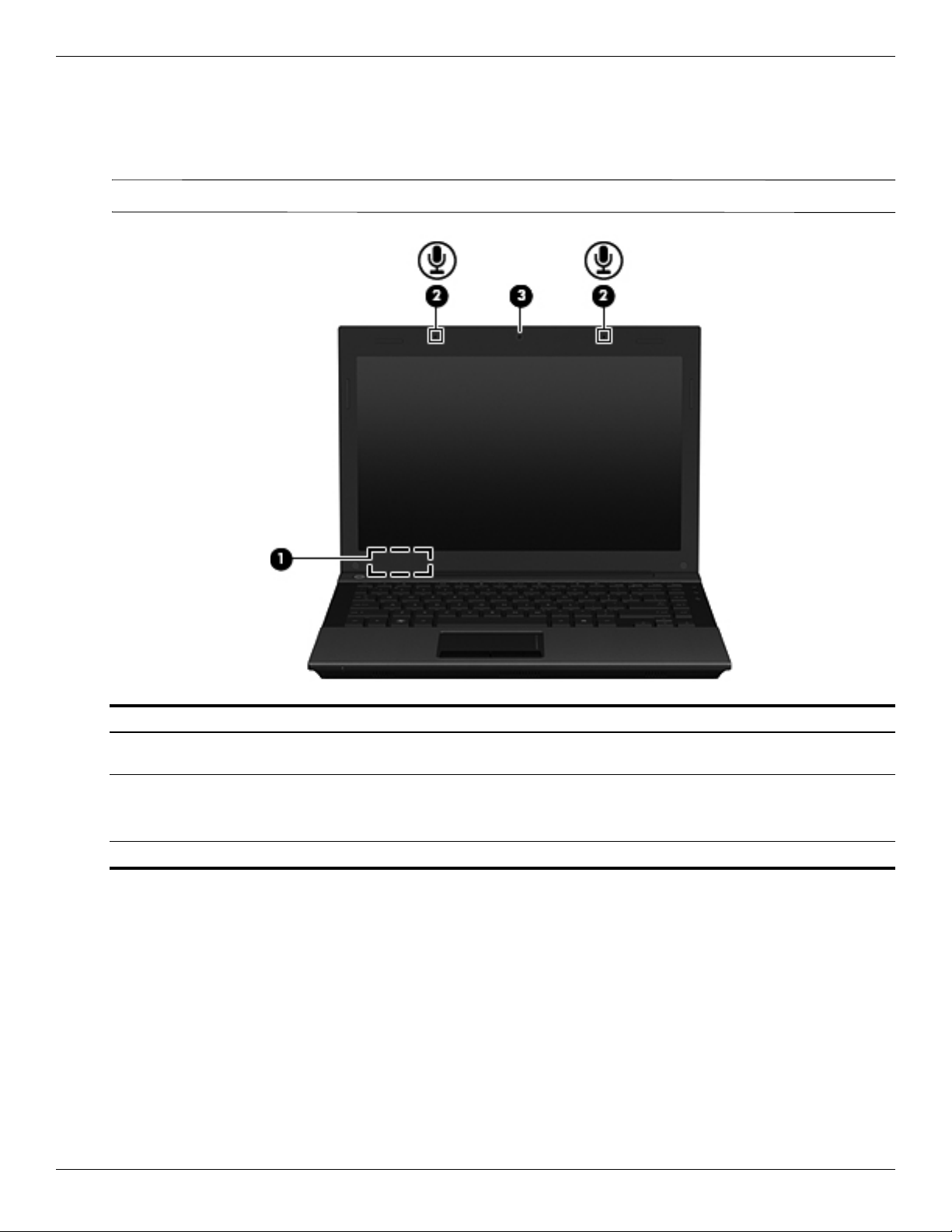
Top components
Display components
Your computer may look slightly different from the illustration in this section.
✎
Item Component Description
(1) Internal display switch Turns off the display and initiates Sleep (Windows 7 and Windows Vista) or
Standby (Windows XP) if the display is closed while the power is on.
(2) Internal microphones (2) Record sound.
If there is a microphone icon next to each microphone opening, your
✎
computer has internal microphones.
(3) Webcam Records video and captures still photographs.
2–2 Maintenance and Service Guide
Page 14
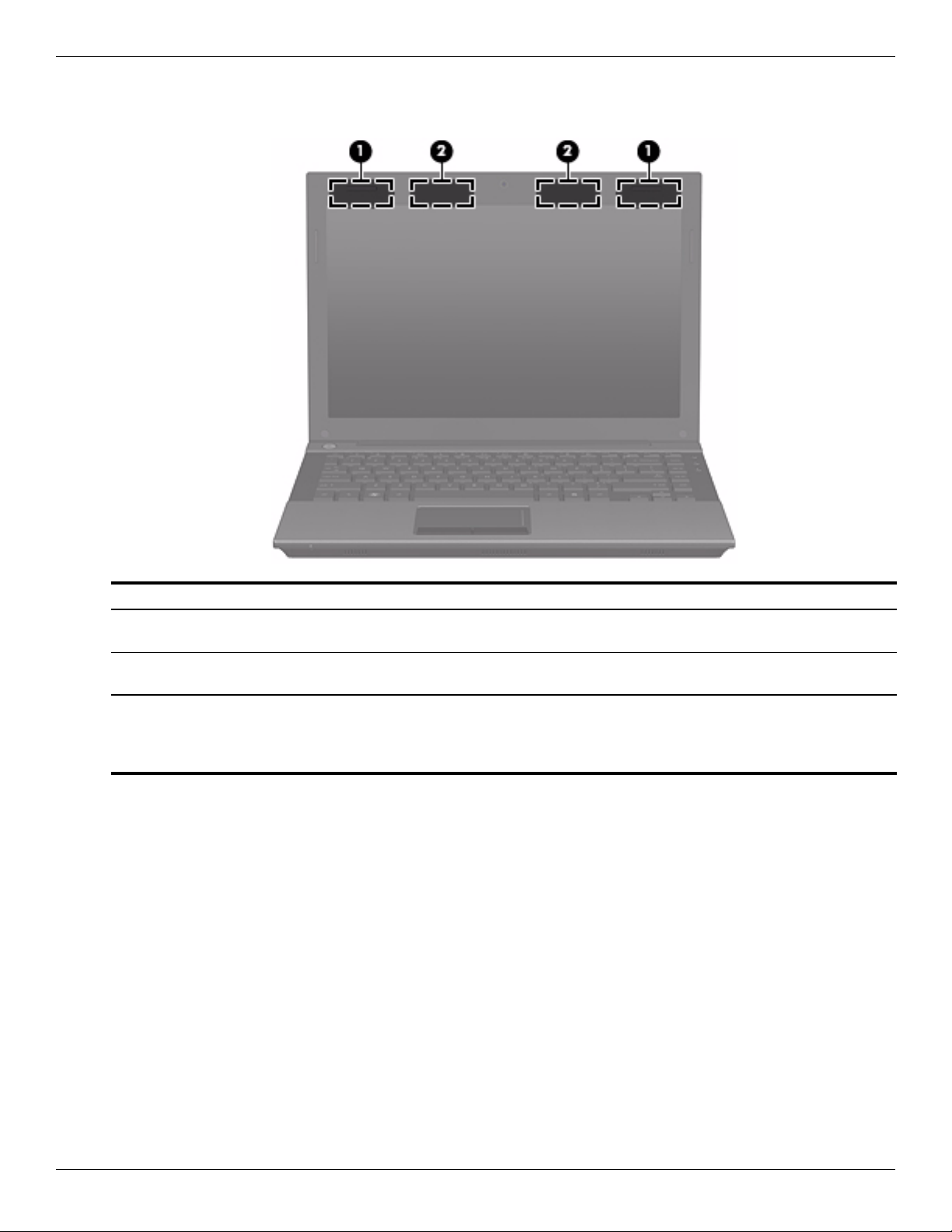
Wireless antennas (select models only)
External component identification
Item Component Description
(1) WWAN antennas (2)* (select
models only)
(2) WLAN antennas (2)* (select
models only)
*The antennas are not visible from the outside of the computer. For optimal transmission, keep the areas immediately around
the antennas free from obstructions.
To see wireless regulatory notices, refer to the section of the Regulatory, Safety and Environmental Notices that applies to
your country or region. These notices are located in Help and Support.
Send and receive wireless signals to communicate with wireless wide-area
networks (WWANs).
Send and receive wireless signals to communicate with wireless local area
networks (WLANs).
Maintenance and Service Guide 2–3
Page 15
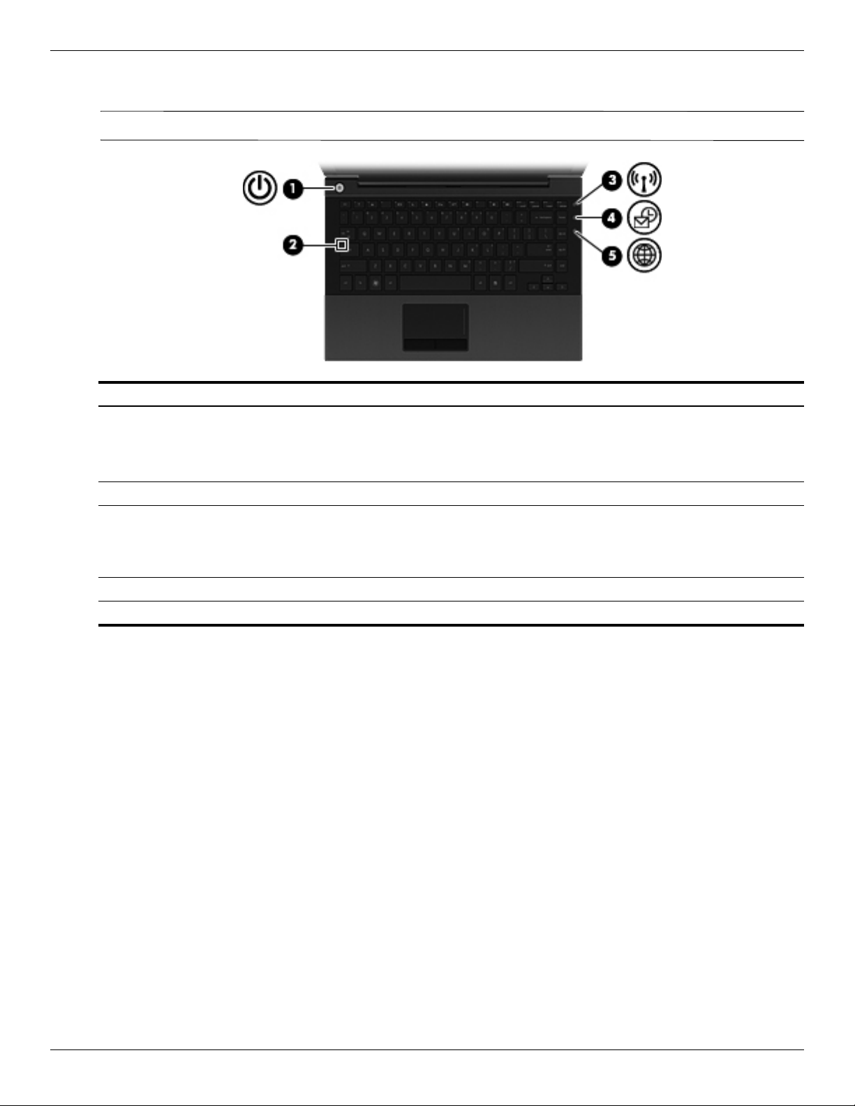
External component identification
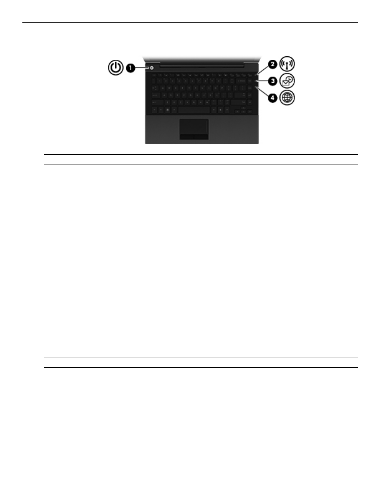
Buttons
Item Component Description
(1) Power button ■ When the computer is off, press the button to turn on the computer.
■ When the computer is on, press the button to shut down the computer.
Although you can shut down the computer with the power button, the
✎
recommended procedure is to use the Windows Shut Down command.
■ When the computer is in the Sleep state (Windows 7 and Windows Vista)
or Standby (Windows XP), press the button briefly to exit the Sleep state
(Windows 7 and Windows Vista) or Standby (Windows XP).
■ When the computer is in Hibernation, press the button briefly to exit
Hibernation.
If the computer has stopped responding and Windows shutdown procedures
are ineffective, press and hold the power button for at least 5 seconds to turn
off the computer.
To learn more about your power settings:
■ In Windows 7: Select Start > Control Panel > System and Security >
Power Options.
■ In Windows Vista: Select Start > Control Panel > System and
Maintenance > Power Options.
■ In Windows XP: Select Start > Control Panel > Performance and
Maintenance > Power Options.
(2) Wireless button Turns the wireless feature on or off but does not establish a
wireless connection.
(3) QuickLook button Allows you to save calendar, contact, inbox, and task information from
Microsoft Outlook to the hard drive of your computer. When the computer is
off or in Hibernation, you can press the QuickLook button to view this
information without waiting for the operating system to restart.
(4) QuickWeb button Opens the Web browser.
2–4 Maintenance and Service Guide
Page 16
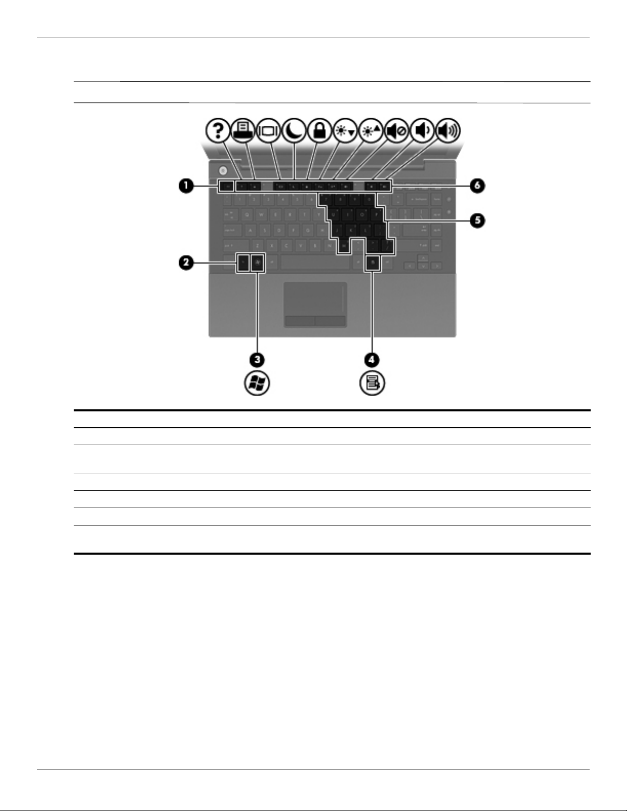
Keys
✎
External component identification
Your computer may look slightly different from the illustration in this section.
Item Component Description
(1)
(2)
(3) Windows logo key Displays the Windows Start menu.
(4) Windows applications key Displays a shortcut menu for items beneath the pointer.
(5) Embedded numeric keypad keys Can be used like the keys on an external numeric keypad.
(6) Function keys Execute frequently used system functions when pressed in combination with
esc key Displays system information when pressed in combination with the fn key.
fn key Executes frequently used system functions when pressed in combination with
a function key or the
fn key.
the
esc key.
Maintenance and Service Guide 2–5
Page 17
External component identification
Lights
Your computer may look slightly different from the illustration in this section.
✎
Item Component Description
(1) Power light ■ On: The computer is on.
(2) Caps lock light On: Caps lock is on.
(3) Wireless light ■ Blue: An integrated wireless device, such as a WLAN device, the
■ Blinking: The computer is in the Sleep state (Windows 7 and
Windows Vista) or Standby (Windows XP).
■ Off: The computer is off or in Hibernation.
HP Mobile Broadband Module (select models only), and/or a Bluetooth
device, is on.
■ Amber: All wireless devices are off.
(4) QuickLook light Turns on briefly when the QuickLook button is pressed.
(5) QuickWeb light Turns on briefly when the QuickWeb button is pressed.
2–6 Maintenance and Service Guide
Page 18
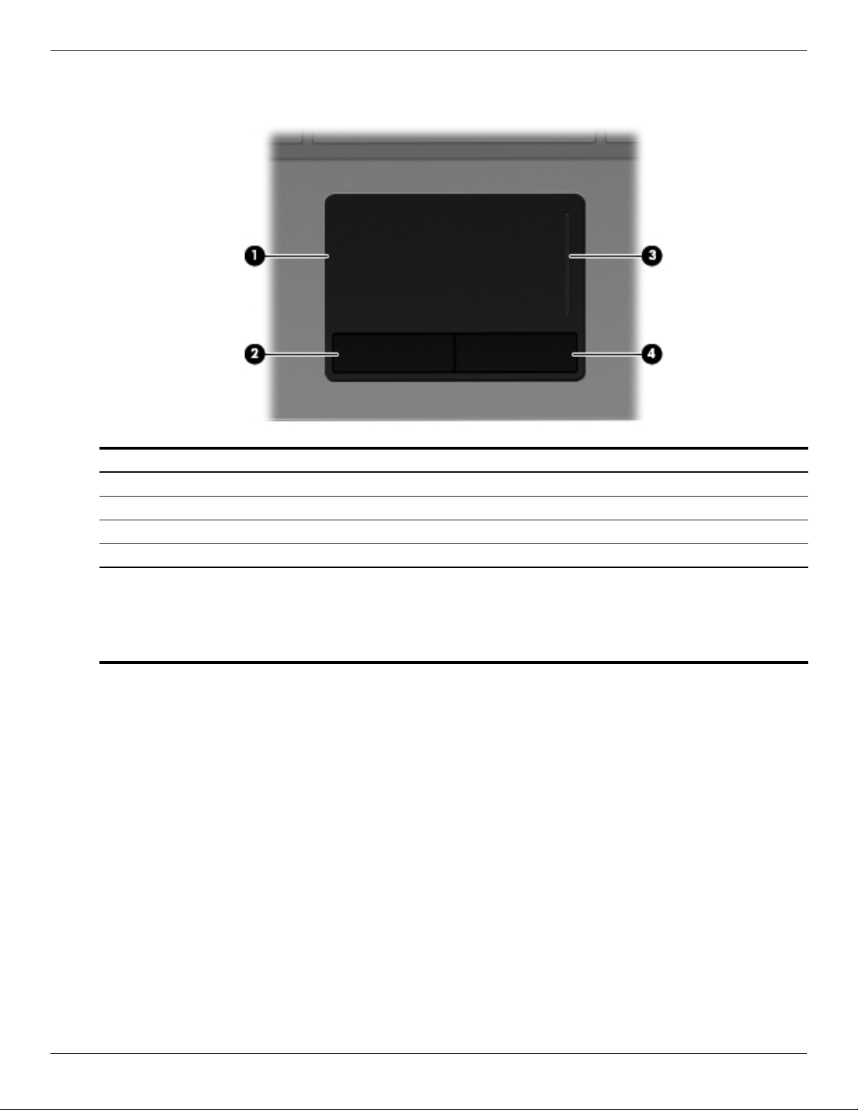
Pointing devices
External component identification
Item Component Description
(1) TouchPad* Moves the pointer and selects or activates items on the screen.
(2) Left TouchPad button* Functions like the left button on an external mouse.
(3) TouchPad scroll zone Scrolls up or down.
(4) Right TouchPad button* Functions like the right button on an external mouse.
*This table describes factory settings. To view or change pointing device preferences:
■ In Windows 7: Select Start > Devices and Printers. Then, right-click the device representing your computer, and select
Mouse settings.
■ In Windows Vista: Select Start > Control Panel > Hardware and Sound > Mouse.
■ In Windows XP: Select Start > Control Panel > Printers and Other Hardware > Mouse.
Maintenance and Service Guide 2–7
Page 19
External component identification
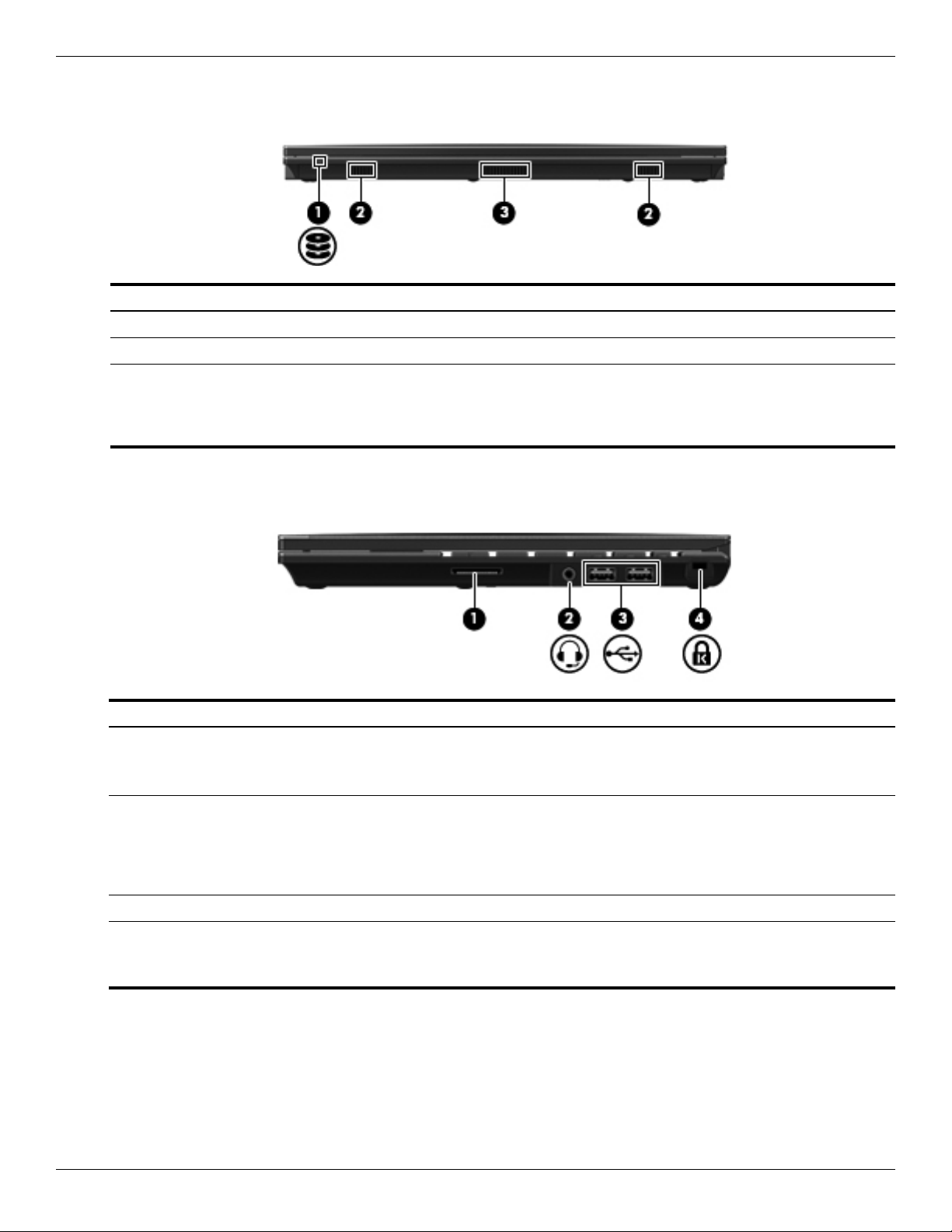
Front components
Item Component Description
(1) Drive light Blinking: The hard drive or an external optical drive is being accessed.
(2) Speakers (2) Produce sound.
(3) Vent Enables airflow to cool internal components.
Right-side components
The computer fan starts up automatically to cool internal components
✎
and prevent overheating. It is normal for the internal fan to cycle on and
off during routine operation.
Item Component Description
(1) SD Card Reader Supports the following optional digital card formats:
■ MultiMediaCard (MMC)
■ Secure Digital (SD) Memory Card
(2) Combo headphone microphone jack Produces sound when connected to optional powered stereo speakers,
headphones, ear buds, a headset, or television audio. Also connects an
optional headset microphone.
When a device is connected to the headphone jack, the computer
✎
speakers are disabled.
(3) USB ports (2) Connect optional USB devices.
(4) Security cable slot Attaches an optional security cable to the computer.
The security cable is designed to act as a deterrent, but it may not
✎
prevent the computer from being mishandled or stolen.
2–8 Maintenance and Service Guide
Page 20
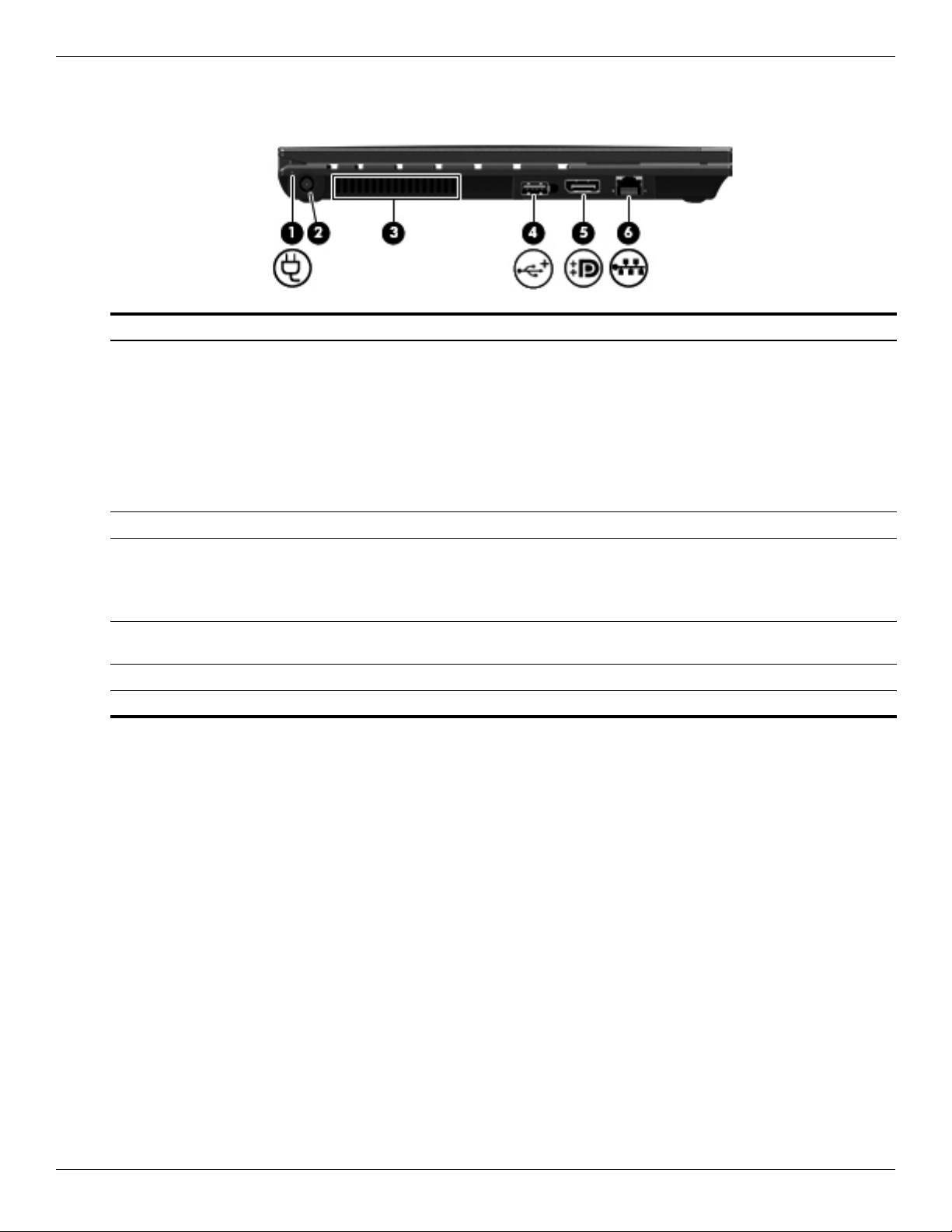
Left-side components
Item Component Description
(1) Battery light ■ Amber: A battery is charging.
(2) Power connector Connects an AC adapter.
(3) Vent Enables airflow to cool internal components.
(4) Powered USB port Provides power to a USB device, such as an optional external MultiBay or an
(5) DisplayPort Connects an external VGA monitor or projector.
External component identification
■ Blue: A battery is close to full charge capacity.
■ Blinking amber: A battery that is the only available power source has
reached a low battery level. When the battery reaches a critical battery
level, the battery light begins blinking rapidly.
■ Off: If the computer is plugged into an external power source, the light turns
off when all batteries in the computer are fully charged. If the computer is
not plugged into an external power source, the light stays off until the
battery reaches a low battery level.
The computer fan starts up automatically to cool internal components
✎
and prevent overheating. It is normal for the internal fan to cycle on and
off during routine operation.
optional external optical drive, if used with a powered USB cable.
(6) RJ-45 (network) jack Connects a network cable.
Maintenance and Service Guide 2–9
Page 21
External component identification
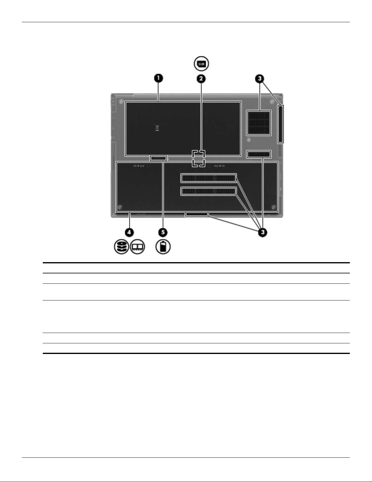
Bottom components
Item Component Description
(1) Battery bay Holds the battery.
(2) SIM slot (select models only) Contains a wireless subscriber identity module (SIM). The SIM slot is located
inside the battery bay.
(3) Vents (6) Enable airflow to cool internal components.
The computer fan starts up automatically to cool internal components
✎
and prevent overheating. It is normal for the internal fan to cycle on and
off during routine operation.
(4) Hard drive bay Holds the hard drive and contains the memory module slot.
(5) Battery release latch Releases the battery from the battery bay.
2–10 Maintenance and Service Guide
Page 22
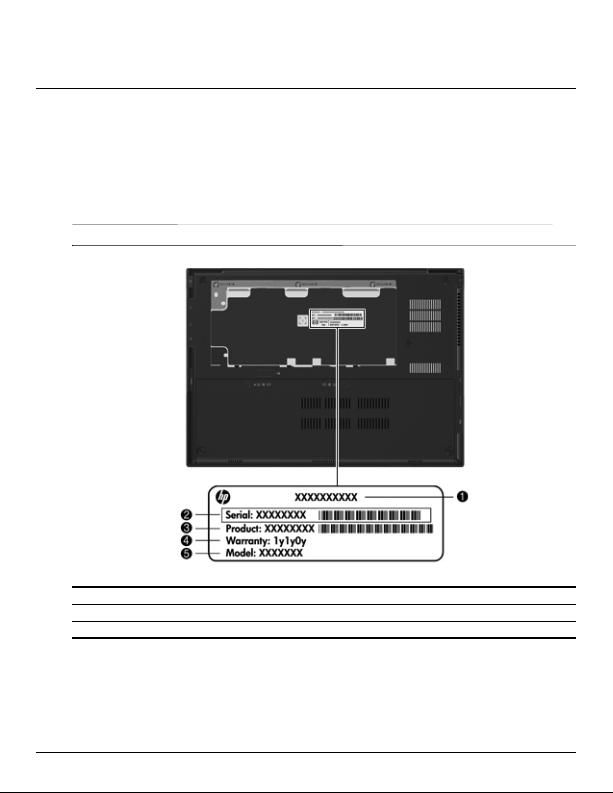
Serial number label location
When ordering parts or requesting information, the serial number label, located on the bottom of the computer,
provides important information that you may need when contacting technical support.
Serial number label location, format, and color vary on select models.
✎
3
Illustrated parts catalog
(1) Product name (4) Warranty period
(2) Serial number (5) Model description (select models only)
(3) Product number
Maintenance and Service Guide 3–1
Page 23
Illustrated parts catalog
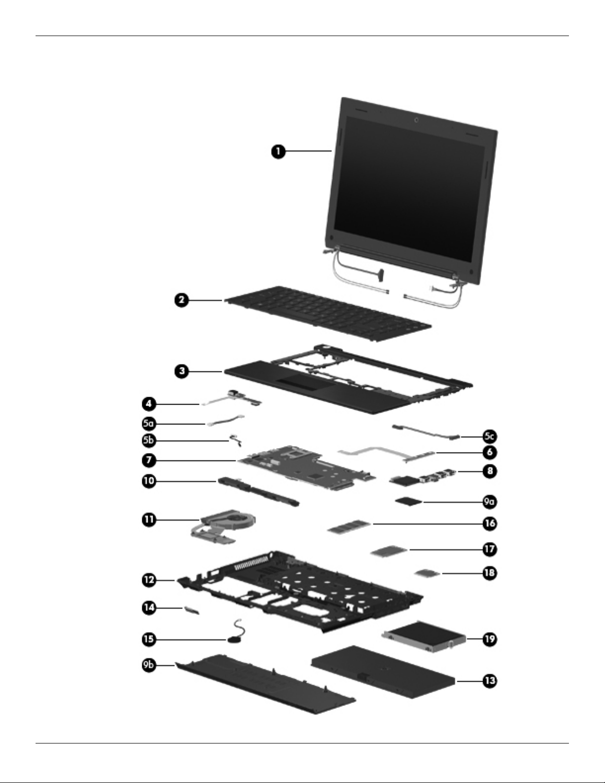
Computer major components
3–2 Maintenance and Service Guide
Page 24

Illustrated parts catalog
Item Description Spare part number
(1) Display assembly (includes 2 WLAN antenna transceivers and cables, 2 WWAN antenna transceivers and cables,
webcam, nameplate, and logo):
13.3-in, high-definition (HD), LED, AntiGlare display assembly 618827-001
13.3-in, HD, LED, BrightView display assembly 618828-001
See “Display assembly subcomponents” on page 3-7 for display assembly internal component spare
✎
part information.
(2) Keyboard (includes keyboard cable):
For use in Belgium 618843-A41
For use in Bulgaria 618843-261
For use in the Czech Republic and Slovakia 618843-A81
For use in Denmark 618843-081
For use in France 618843-051
For use in France and Arabia 618843-DW1
For use in French Canada 618843-121
For use in Germany 618843-041
For use in Greece 618843-DJ1
For use in Hungary 618843-211
For use in Iceland 618843-DD1
For use in Israel 618843-BB1
For use in Italy 618843-061
For use in Japan 618843-291
For use in the Netherlands 618843-B31
For use in Norway 618843-091
For use in Portugal 618843-131
For use in Russia 618843-251
For use in Saudi Arabia 618843-171
For use in Slovenia 618843-BA1
For use in South Korea 618843-AD1
For use in Spain 618843-071
For use in Sweden and Finland 618843-B71
For use in Switzerland 618843-BG1
For use in Taiwan 618843-AB1
For use in Thailand 618843-281
For use in Turkey 618843-141
For use in the United Kingdom 618843-031
For use in the United States 618843-001
(Continued)
Maintenance and Service Guide 3–3
Page 25

Illustrated parts catalog
Item Description Spare part number
(3) Top cover with fingerprint reader (includes TouchPad button board and cable, and
TouchPad board and cable)
Top cover with fingerprint reader (includes TouchPad button board and cable, and
TouchPad board and cable)
(4) Power button board with FFC (includes cable) 618816-001
Cable Kit, includes: 618826-001
(5a) Power button board cable
(5b) Bluetooth module cable
(5c) USB board cable
See “Cable Kit” on page 3-6 for more Cable Kit spare part information.
✎
(6) Button board with FFC (includes cable) 618815-001
(7) System board (includes processor and replacement thermal material):
System board with Intel® Dual Core i5-45M 2.40-GHz processor (Turbo up to 2.53 GHz),
3-M L3 cache, 4 threads (35W)
System board with Intel® Dual Core i5-45M 2.40-GHz processor (Turbo up to 2.53 GHz),
3-M L3 cache, 4 threads (35W), for use in China and Russia
System board with Intel Dual Core i3-370M 2.40-GHz processor, 3-M L3 cache, 4 threads
(35W)
System board with Intel Dual Core i3-370M 2.40-GHz processor, 3-M L3 cache, 4 threads
(35W), for use in China and Russia
618840-001
618841-001
618821-001
618822-001
618819-001
618820-001
System board with Intel Dual Core i3-350M 2.26-GHz processor, 3-M L3 cache, 4 threads
(35W)
System board with Intel Dual Core i3-350M 2.26-GHz processor, 3-M L3 cache, 4 threads
(35W), for use in China and Russia
System board with Intel U3400 1.06-GHz processor 618823-001
System board with Intel U3400 1.06-GHz processor, for use in China and Russia 618824-001
(8) USB board (includes cable) 618825-001
Plastics Kit, includes: 618835-001
(9a) SD Card Reader slot bezel
(9b) Accessory cover (includes 2 captive screws)
See “Plastics Kit” on page 3-9 for more Plastics Kit spare part information.
✎
(10) Speaker assembly (includes cable) 618839-001
(11) Fan/Heat sink (includes replacement thermal material) 618830-001
(12) Base enclosure (includes 6 rubber feet) 618813-001
Latch Kit (not illustrated, includes battery eject arm, latch, and spring) 581090-001
Rubber Feet Kit (not illustrated, includes 6 rubber feet and 2 display bezel screw covers) 581101-001
(13) 4-cell, 41-WHr, 2.8-Ah battery 580956-001
6-cell, 62-WHr, 2.8-Ah battery (supports HP Fast Charge Technology) 594796-001
(14) Bluetooth module 537921-001
618817-001
618818-001
The Bluetooth module spare part kit does not include a Bluetooth module cable. The Bluetooth module cable is
✎
included in the Cable Kit, spare part number 618826-001.
(Continued)
3–4 Maintenance and Service Guide
Page 26

Illustrated parts catalog
Item Description Spare part number
(15) RTC battery (includes double-sided tape) 481089-001
(16) Memory module:
4096-MB (1333-MHz, DDR3, PC3-10600 Shared) 599092-001
2048-MB (1066-MHz, DDR3, PC3-10600) 581096-001
1024-MB (1066-MHz, DDR3, PC3-10600 Shared) (not available on Microsoft 64-bit
operating systems)
598859-001
(17) HSPA EV-DO WWAN module (does not support Linux operating system; available in all
countries and regions, except China)
(18) WLAN module:
802.11 a/b/g/n WLAN module:
■ Broadcom 43224 802.11 a/g/n WLAN module for use in Antigua and Barbuda, Barbados,
Belize, Canada, the Cayman Islands, Guam, Puerto Rico, Trinidad and Tobago,
the U.S. Virgin Islands, and the United States
■ Broadcom 43224 802.11 a/g/n WLAN module for use in Afghanistan, Albania, Algeria,
Andorra, Angola, Argentina, Armenia, Aruba, Australia, Austria, Azerbaijan,
the Bahamas, Bahrain, Bangladesh, Barbados, Belarus, Belgium, Belize, Benin,
Bermuda, Bhutan, Bolivia, Bosnia and Herzegovina, Botswana, Brazil,
the British Virgin Islands, Brunei, Bulgaria, Burkina Faso, Burundi, Cambodia,
Cameroon, Cape Verde, the Central African Republic, Chad, Chile, Colombia, Comoros,
the Congo, Costa Rica, Croatia, Cyprus, the Czech Republic, Denmark, Djibouti,
Dominica, the Dominican Republic, East Timor, Ecuador, Egypt, El Salvador,
Equatorial Guinea, Eritrea, Estonia, Ethiopia, Fiji, Finland, France, French Guiana,
Gabon, Gambia, Georgia, Germany, Ghana, Gibraltar, Greece, Grenada, Guadeloupe,
Guatemala, Guinea, Guinea-Bissau, Guyana, Haiti, Honduras, Hong Kong, Hungary,
Iceland, India, Indonesia, Ireland, Italy, the Ivory Coast, Jamaica, Japan, Jordan,
Kazakhstan, Kenya, Kiribati, Kuwait, Kyrgyzstan, Laos, Latvia, Lebanon, Lesotho,
Liberia, Liechtenstein, Lithuania, Luxembourg, Macedonia, Madagascar, Malawi,
Malaysia, the Maldives, Mali, Malta, the Marshall Islands, Martinique, Mauritania,
Mauritius, Mexico, Micronesia, Monaco, Mongolia, Montenegro, Morocco, Mozambique,
Namibia, Nauru, Nepal, the Nether Antilles, the Netherlands, New Zealand, Nicaragua,
Niger, Nigeria, Norway, Oman, Pakistan, Palau, Panama, Papua New Guinea, Paraguay,
the People’s Republic of China, Peru, the Philippines, Poland, Portugal, Qatar,
the Republic of Moldova, Romania, Russia, Rwanda, Samoa, San Marino,
Sao Tome and Principe, Saudi Arabia, Senegal, Serbia, the Seychelles, Sierra Leone,
Singapore, Slovakia, Slovenia, the Solomon Islands, Somalia, South Africa,
South Korea, Spain, Sri Lanka, St. Kitts and Nevis, St. Lucia, St. Vincent, Suriname,
Swaziland, Sweden, Switzerland, Taiwan, Tajikistan, Tanzania, Thailand, Togo, Tonga,
Tunisia, Turkey, Turkmenistan, Tuvalu, Uganda, Ukraine, the United Arab Emirates,
the United Kingdom, Uruguay, Uzbekistan, Vanuatu, Venezuela, Vietnam, Yemen, Zaire,
Zambia, and Zimbabwe
(18) 802.11 b/g/n WLAN module:
531993-001
582564-001
582564-002
■ Broadcom 4312G 802.11 b/g/n WLAN module for use in Canada, the Cayman Islands,
Guam, Puerto Rico, the United States, and the U.S. Virgin Islands
(19) Mass storage device (includes bracket):
Hard drive:
■ 500-GB, 7200 rpm 618829-001
■ 320-GB, 7200 rpm 581084-001
■ 250-GB, 7200 rpm 581083-001
Solid-state drive (only with computer models running Windows 7 operating system, 2 GB or 4 GB):
■ 128-GB 581085-001
■ 80-GB 581086-001
Maintenance and Service Guide 3–5
593836-001
Page 27
Illustrated parts catalog
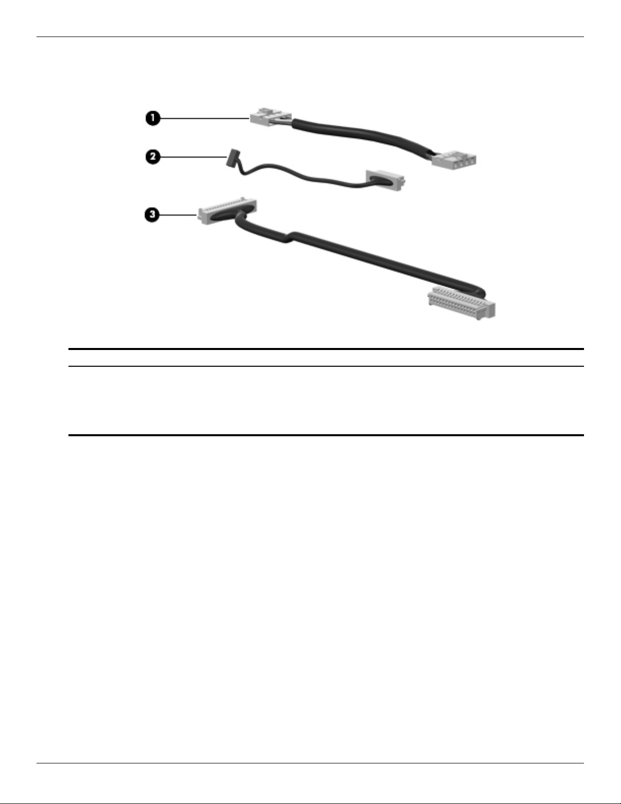
Cable Kit
Item Description Spare part number
Cable Kit: 618826-001
(1) Power button board cable
(2) Bluetooth module cable
(3) USB board cable
3–6 Maintenance and Service Guide
Page 28
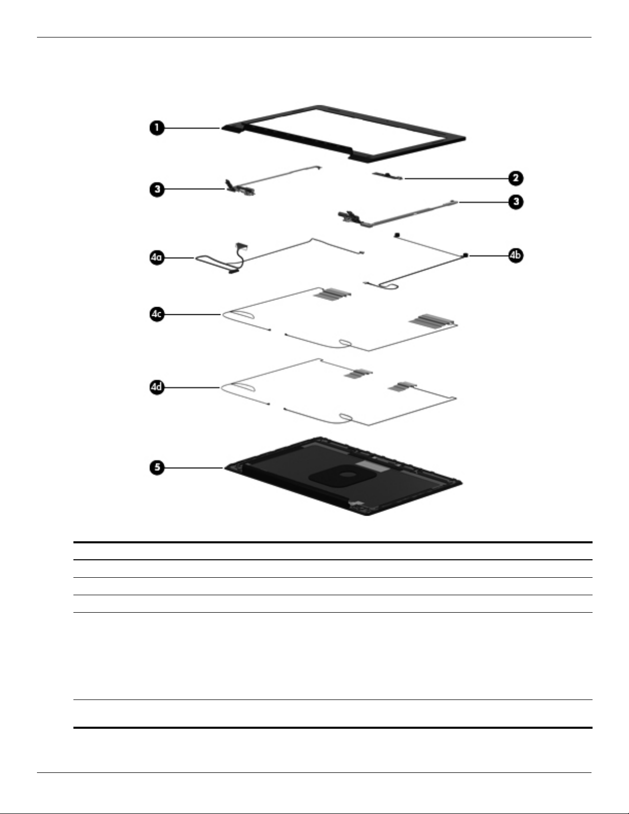
Display assembly subcomponents
Illustrated parts catalog
Item Description Spare part number
(1) Display bezel 618832-001
(2) Webcam module 618842-001
(3) Display Hinge Kit (includes left and right hinges) 581094-001
Display Cable Kit, includes: 618833-001
(4a) Display panel cable and webcam cable
(4b) Microphones and cables
(4c) WWAN antenna transceivers and cables
(4d) WLAN antenna transceivers and cables
(5) Display enclosure (includes microphones and cables, WLAN antenna transceivers and
cables, and WWAN antenna transceivers and cables)
Maintenance and Service Guide 3–7
618831-001
Page 29
Illustrated parts catalog
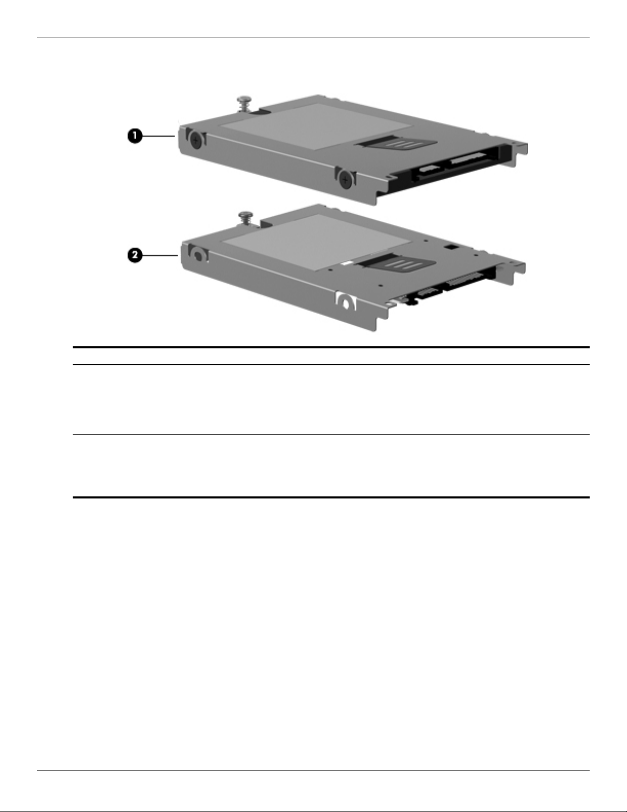
Mass storage devices
Item Description Spare part number
(1) Hard drive (includes bracket):
500-GB, 7200 rpm 618829-001
320-GB, 7200 rpm 581084-001
250-GB, 7200 rpm 581083-001
(2) Solid-state drive (includes bracket), only with computer models running Windows 7 operating system, either 2 GB or
4 GB:
128-GB 581085-001
80-GB 581086-001
3–8 Maintenance and Service Guide
Page 30
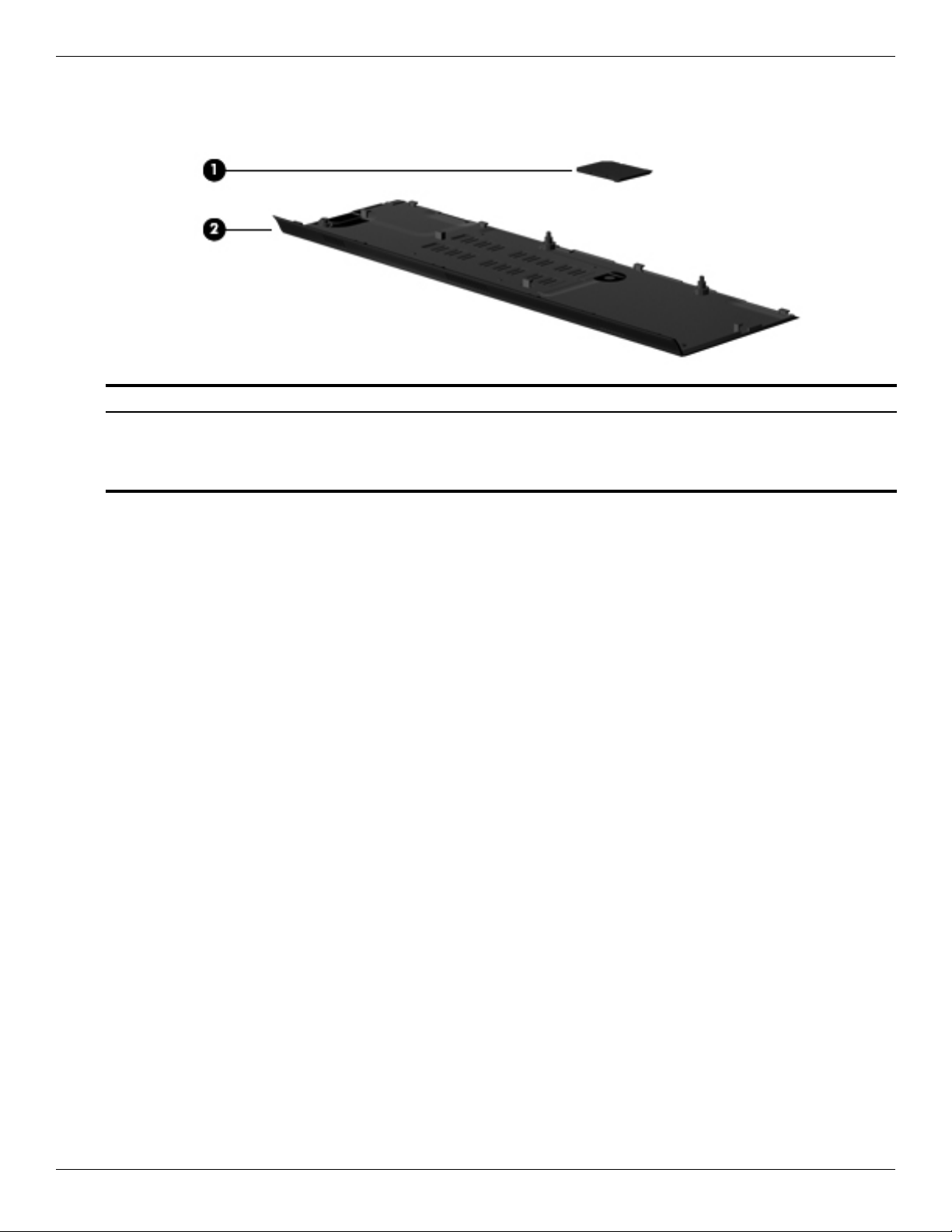
Plastics Kit
Item Description Spare part number
(1) SD Card Reader slot bezel
(2) Accessory cover (includes 2 captive screws)
Illustrated parts catalog
Plastics Kit: 618835-001
Maintenance and Service Guide 3–9
Page 31

Illustrated parts catalog
Miscellaneous parts
Description Spare part number
65-W PFC RC/V HP Smart Adapter 613161-001
65-W PFC RC/V HP Slim Adapter (for use only in Japan) 613152-001
Power cord:
For use in Australia 490371-011
For use in Denmark 490371-081
For use in Europe, the Middle East, and Africa 490371-021
For use in India 490371-D61
For use in Israel 490371-BB1
For use in Italy 490371-061
For use in Japan 490371-291
For use in the People’s Republic of China 490371-AA1
For use in South Africa 490371-AR1
For use in South Korea 490371-AD1
For use in Switzerland 490371-111
For use in Taiwan 490371-AB1
For use in the United Kingdom and Singapore 490371-031
For use in the United States 490371-001
Screw Kit:
Phillips PM3.0×4.0 screw
Phillips PM2.5×11.0 captive screw
Phillips PM2.5×6.0 captive screw
Phillips PM2.5×5.0 screw
Phillips PM2.5×4.0 broadhead screw
Phillips PM2.5×4.0 screw
Phillips PM2.5×2.0 broadhead screw
Slotted Torx T8M2.5×7.0 screw
Torx T8M2.5×9.0 screw
Torx T8M2.0×7.0 captive screw
Torx T8M2.5×6.0 screw
Torx T8M2.5×5.0 screw
Torx T8M2.5×4.0 screw
618838-001
3–10 Maintenance and Service Guide
Page 32

Sequential part number listing
Spare part number Description
481089-001 RTC battery (includes double-sided tape)
490371-001 Power cord for use in the United States
490371-011 Power cord for use in Australia
490371-021 Power cord for use in Europe, the Middle East, and Africa
490371-031 Power cord for use in the United Kingdom and Singapore
490371-061 Power cord for use in Italy
490371-081 Power cord for use in Denmark
490371-111 Power cord for use in Switzerland
490371-291 Power cord for use in Japan
490371-AA1 Power cord for use in the People’s Republic of China
490371-AB1 Power cord for use in Taiwan
490371-AD1 Power cord for use in South Korea
490371-AR1 Power cord for use in South Africa
Illustrated parts catalog
490371-BB1 Power cord for use in Israel
490371-D61 Power cord for use in India
531993-001 HSPA EV-DO WWAN module (does not support Linux operating system; available in all countries and
regions, except China)
537921-001 Bluetooth module
The Bluetooth module spare part kit does not include a Bluetooth module cable. The Bluetooth
✎
module cable is included in the Cable Kit, spare part number 618826-001.
580956-001 4-cell, 41-WHr, 2.8-Ah battery
581094-001 Display Hinge Kit (includes left and right hinges)
581096-001 2048-MB memory module (1333-MHz, DDR3)
581083-001 250-GB, 7200-rpm hard drive (includes bracket)
581084-001 320-GB, 7200-rpm hard drive (includes bracket)
581085-001 128-GB solid-state drive (includes bracket), only with computer models running Windows 7 operating
system, either 2 GB or 4 GB
581086-001 80-GB solid-state drive (includes bracket), only with computer models running Windows 7 operating
system, either 2 GB or 4 GB
581090-001 Latch Kit (includes battery eject arm, latch, and spring)
581101-001 Rubber Feet Kit (includes 6 rubber feet and 2 display bezel screw covers)
582564-001 Broadcom 43224 802.11 a/b/g/n WLAN module for use in Antigua and Barbuda, Barbados, Belize,
Canada, the Cayman Islands, Guam, Puerto Rico, Trinidad and Tobago, the U.S. Virgin Islands,
and the United States
(Continued)
Maintenance and Service Guide 3–11
Page 33

Illustrated parts catalog
Spare part number Description
582564-002 Broadcom 43224 802.11 a/b/g/n WLAN module for use in Afghanistan, Albania, Algeria, Andorra,
593836-001 Broadcom 4312G 802.11 b/g/n WLAN module for use in Canada, the Cayman Islands, Guam,
Angola, Argentina, Armenia, Aruba, Australia, Austria, Azerbaijan, the Bahamas, Bahrain,
Bangladesh, Barbados, Belarus, Belgium, Belize, Benin, Bermuda, Bhutan, Bolivia,
Bosnia and Herzegovina, Botswana, Brazil, the British Virgin Islands, Brunei, Bulgaria, Burkina Faso,
Burundi, Cambodia, Cameroon, Cape Verde, the Central African Republic, Chad, Chile, Colombia,
Comoros, the Congo, Costa Rica, Croatia, Cyprus, the Czech Republic, Denmark, Djibouti,
Dominica, the Dominican Republic, East Timor, Ecuador, Egypt, El Salvador, Equatorial Guinea,
Eritrea, Estonia, Ethiopia, Fiji, Finland, France, French Guiana, Gabon, Gambia, Georgia, Germany,
Ghana, Gibraltar, Greece, Grenada, Guadeloupe, Guatemala, Guinea, Guinea-Bissau, Guyana,
Haiti, Honduras, Hong Kong, Hungary, Iceland, India, Indonesia, Ireland, Italy, the Ivory Coast,
Jamaica, Japan, Jordan, Kazakhstan, Kenya, Kiribati, Kuwait, Kyrgyzstan, Laos, Latvia, Lebanon,
Lesotho, Liberia, Liechtenstein, Lithuania, Luxembourg, Macedonia, Madagascar, Malawi, Malaysia,
the Maldives, Mali, Malta, the Marshall Islands, Martinique, Mauritania, Mauritius, Mexico,
Micronesia, Monaco, Mongolia, Montenegro, Morocco, Mozambique, Namibia, Nauru, Nepal,
the Nether Antilles, the Netherlands, New Zealand, Nicaragua, Niger, Nigeria, Norway, Oman,
Pakistan, Palau, Panama, Papua New Guinea, Paraguay, the People’s Republic of China, Peru,
the Philippines, Poland, Portugal, Qatar, the Republic of Moldova, Romania, Russia, Rwanda,
Samoa, San Marino, Sao Tome and Principe, Saudi Arabia, Senegal, Serbia, the Seychelles,
Sierra Leone, Singapore, Slovakia, Slovenia, the Solomon Islands, Somalia, South Africa,
South Korea, Spain, Sri Lanka, St. Kitts and Nevis, St. Lucia, St. Vincent, Suriname, Swaziland,
Sweden, Switzerland, Taiwan, Tajikistan, Tanzania, Thailand, Togo, Tonga, Tunisia, Turkey,
Turkmenistan, Tuvalu, Uganda, Ukraine, the United Arab Emirates, the United Kingdom, Uruguay,
Uzbekistan, Vanuatu, Venezuela, Vietnam, Yemen, Zaire, Zambia, and Zimbabwe
Puerto Rico, the United States, and the U.S. Virgin Islands
594796-001 6-cell, 62-WHr, 2.8-Ah battery (supports HP Fast Charge technology)
598859-001 1024-MB memory module (1333-MHz, DDR3, PC3-10600 Shared) (not available on Microsoft 64-bit
operating systems)
599092-001 4096-MB memory module (1333-MHz, DDR3, PC3-10600 Shared)
613152-001 65-W PFC RC/V HP Slim Adapter
613161-001 65-W PFC RC/V HP Smart Adapter (for use only in Japan)
618813-001 Base enclosure (includes 6 rubber feet)
618815-001 Button board with FFC (includes cable)
618816-001 Power button board with FFC (includes cable)
618817-001 System board with Intel Dual Core i3-350M 2.26-GHz processor, 3-M L3 cache, 4 threads (35W)
618818-001 System board with Intel Dual Core i3-350M 2.26-GHz processor, 3-M L3 cache, 4 threads (35W), for
use in China and Russia
618819-001 System board with Intel Dual Core i3-370M 2.40-GHz processor, 3-M L3 cache, 4 threads (35W)
618820-001 System board with Intel Dual Core i3-370M 2.40-GHz processor, 3-M L3 cache, 4 threads (35W), for
use in China and Russia
618821-001 System board with Intel® Dual Core i5-45M 2.40-GHz processor (Turbo up to 2.53 GHz), 3-M L3
cache, 4 threads (35W)
618822-001 System board with Intel® Dual Core i5-45M 2.40-GHz processor (Turbo up to 2.53 GHz), 3-M L3
cache, 4 threads (35W), for use in China and Russia
618823-001 System board with Intel U3400 1.06-GHz processor
618824-001 System board with Intel U3400 1.06-GHz processor, for use in China and Russia
618825-001 USB board (includes cable)
618826-001 Cable Kit
See “Cable Kit” on page 3-6 for more Cable Kit spare part information.
✎
(Continued)
3–12 Maintenance and Service Guide
Page 34

Illustrated parts catalog
Spare part number Description
618827-001 13.3-in, HD, LED, AntiGlare display assembly (includes 2 WLAN antenna transceivers and cables,
2 WWAN antenna transceivers and cables, webcam, nameplate, and logo)
618828-001 13.3-in, HD, LED, BrightView display assembly (includes 2 WLAN antenna transceivers and cables,
2 WWAN antenna transceivers and cables, webcam, nameplate, and logo)
618829-001 500-GB, 7200-rpm hard drive (includes bracket)
618830-001 Fan/Heat sink (includes replacement thermal material)
618831-001 Display enclosure (includes microphones and cables, WLAN antenna transceivers and cables, and
WWAN antenna transceivers and cables)
618832-001 Display bezel
618833-001 Display Cable Kit (includes display panel cable and webcam cable, microphones and cables, WLAN
antenna transceivers and cables, and WWAN antenna transceivers and cables)
618835-001 Plastics Kit
See “Plastics Kit” on page 3-9 for more Plastics Kit spare part information.
✎
618838-001 Screw Kit
618839-001 Speaker assembly (includes cable)
618840-001 Top cover with fingerprint reader (includes TouchPad button board and cable, and TouchPad board
and cable)
618841-001 Top cover with no fingerprint reader (includes TouchPad button board and cable, and TouchPad board
and cable)
618842-001 Webcam module
618843-001 Keyboard for use in the United States (includes keyboard cable)
618843-031 Keyboard for use in the United Kingdom (includes keyboard cable)
618843-041 Keyboard for use in Germany (includes keyboard cable)
618843-051 Keyboard for use in France (includes keyboard cable)
618843-061 Keyboard for use in Italy (includes keyboard cable)
618843-071 Keyboard for use in Spain (includes keyboard cable)
618843-081 Keyboard for use in Denmark (includes keyboard cable)
618843-091 Keyboard for use in Norway (includes keyboard cable)
618843-121 Keyboard for use in French Canada (includes keyboard cable)
618843-131 Keyboard for use in Portugal (includes keyboard cable)
618843-141 Keyboard for use in Turkey (includes keyboard cable)
618843-171 Keyboard for use in Saudi Arabia (includes keyboard cable)
618843-211 Keyboard for use in Hungary (includes keyboard cable)
618843-251 Keyboard for use in Russia (includes keyboard cable)
618843-261 Keyboard for use in Bulgaria (includes keyboard cable)
618843-281 Keyboard for use in Thailand (includes keyboard cable)
618843-291 Keyboard for use in Japan (includes keyboard cable)
618843-A41 Keyboard for use in Belgium (includes keyboard cable)
618843-A81 Keyboard for use in the Czech Republic and Slovakia(includes keyboard cable)
618843-AB1 Keyboard for use in Taiwan (includes keyboard cable)
(Continued)
Maintenance and Service Guide 3–13
Page 35

Illustrated parts catalog
Spare part number Description
618843-AD1 Keyboard for use in South Korea (includes keyboard cable)
618843-B31 Keyboard for use in the Netherlands (includes keyboard cable)
618843-B71 Keyboard for use in Sweden and Finland (includes keyboard cable)
618843-BA1 Keyboard for use in Slovenia (includes keyboard cable)
618843-BB1 Keyboard for use in Israel (includes keyboard cable)
618843-BG1 Keyboard for use in Switzerland (includes keyboard cable)
618843-DD1 Keyboard for use in Iceland (includes keyboard cable)
618843-DJ1 Keyboard for use in Greece (includes keyboard cable)
618843_DW1 Keyboard for use in France and Arabia (includes keyboard cable)
3–14 Maintenance and Service Guide
Page 36

Removal and replacement procedures
Preliminary replacement requirements
Tools required
You will need the following tools to complete the removal and replacement procedures:
■ Flat-bladed screwdriver
■ Phillips P0 screwdriver
■ Phillips P1 screwdriver
■ Torx T8 screwdriver
Service considerations
The following sections include some of the considerations that you must keep in mind during disassembly and
assembly procedures.
4
As you remove each subassembly from the computer, place the subassembly (and all accompanying screws)
✎
away from the work area to prevent damage.
Plastic parts
CAUTION: Using excessive force during disassembly and reassembly can damage plastic parts. Use care when handling the
Ä
plastic parts. Apply pressure only at the points designated in the maintenance instructions.
Cables and connectors
CAUTION: When servicing the computer, be sure that cables are placed in their proper locations during the reassembly
Ä
process. Improper cable placement can damage the computer.
Cables must be handled with extreme care to avoid damage. Apply only the tension required to unseat or seat the
cables during removal and insertion. Handle cables by the connector whenever possible. In all cases, avoid
bending, twisting, or tearing cables. Be sure that cables are routed in such a way that they cannot be caught or
snagged by parts being removed or replaced. Handle flex cables with extreme care; these cables tear easily.
Maintenance and Service Guide 4–1
Page 37

Removal and replacement procedures
Drive handling
CAUTION: Drives are fragile components that must be handled with care. To prevent damage to the computer,
Ä
damage to a drive, or loss of information, observe these precautions:
■ Before removing or inserting a hard drive, shut down the computer. If you are unsure whether the computer is off
or in Hibernation, turn the computer on, and then shut it down through the operating system.
■ Before handling a drive, be sure that you are discharged of static electricity. While handling a drive, avoid
touching the connector.
■ Handle drives on surfaces covered with at least one inch of shock-proof foam.
■ Avoid dropping drives from any height onto any surface.
■ After removing a hard drive, an optical drive, or a diskette drive, place it in a static-proof bag.
■ Avoid exposing a hard drive to products that have magnetic fields, such as monitors or speakers.
■ Avoid exposing a drive to temperature extremes or liquids.
■ If a drive must be mailed, place the drive in a bubble pack mailer or other suitable form of protective packaging
and label the package “FRAGILE.”
Grounding guidelines
Electrostatic discharge damage
Electronic components are sensitive to electrostatic discharge (ESD). Circuitry design and structure determine the
degree of sensitivity. Networks built into many integrated circuits provide some protection, but in many cases, ESD
contains enough power to alter device parameters or melt silicon junctions.
A discharge of static electricity from a finger or other conductor can destroy static-sensitive devices or
microcircuitry. Even if the spark is neither felt nor heard, damage may have occurred.
An electronic device exposed to ESD may not be affected at all and can work perfectly throughout a normal cycle.
Or, the device may function normally for a while, and then degrade in the internal layers, reducing its life
expectancy.
CAUTION: To prevent damage to the computer when you are removing or installing internal components, observe
Ä
these precautions:
■ Keep components in their electrostatic-safe containers until you are ready to install them.
■ Use nonmagnetic tools.
■ Before touching an electronic component, discharge static electricity by using the guidelines described in
this section.
■ Avoid touching pins, leads, and circuitry. Handle electronic components as little as possible.
■ If you remove a component, place it in an electrostatic-safe container.
4–2 Maintenance and Service Guide
Page 38

Removal and replacement procedures
The following table shows how humidity affects the electrostatic voltage levels generated by different activities.
CAUTION: A product can be degraded by as little as 700 V.
Ä
Typical electrostatic voltage levels
Relative humidity
Event 10% 40% 55%
Walking across carpet 35,000 V 15,000 V 7,500 V
Walking across vinyl floor 12,000 V 5,000 V 3,000 V
Motions of bench worker 6,000 V 800 V 400 V
Removing DIPS from plastic tube 2,000 V 700 V 400 V
Removing DIPS from vinyl tray 11,500 V 4,000 V 2,000 V
Removing DIPS from Styrofoam 14,500 V 5,000 V 3,500 V
Removing bubble pack from PCB 26,500 V 20,000 V 7,000 V
Packing PCBs in foam-lined box 21,000 V 11,000 V 5,000 V
Packaging and transporting guidelines
Follow these grounding guidelines when packaging and transporting equipment:
■ To avoid hand contact, transport products in static-safe tubes, bags, or boxes.
■ Protect ESD-sensitive parts and assemblies with conductive or approved containers or packaging.
■ Keep ESD-sensitive parts in their containers until they arrive at static-free workstations.
■ Place items on a grounded surface before them from their containers.
■ Always be properly grounded when touching a component or assembly.
■ Store reusable ESD-sensitive parts from assemblies in protective packaging or nonconductive foam.
■ Use transporters and conveyors made of antistatic belts and roller bushings. Be sure that mechanized equipment
used for moving materials is wired to ground, and that proper materials are selected to avoid static charging.
When grounding is not possible, use an ionizer to dissipate electric charges.
Maintenance and Service Guide 4–3
Page 39

Removal and replacement procedures
Workstation guidelines
Follow these workstation grounding guidelines:
■ Cover the workstation with approved static-shielding material.
■ Use a wrist strap connected to a properly grounded work surface, and use properly grounded tools and
equipment.
■ Use conductive field service tools, such as cutters, screwdrivers, and vacuums.
■ When fixtures must directly contact dissipative surfaces, use fixtures made only of static-safe materials.
■ Keep the work area free of nonconductive materials, such as ordinary plastic assembly aids and Styrofoam.
■ Handle ESD-sensitive components, parts, and assemblies by the case or PCM laminate. Handle these items
only at static-free workstations.
■ Avoid contact with pins, leads, or circuitry.
■ Turn off power and input signals before inserting or removing connectors or test equipment.
Equipment guidelines
Grounding equipment must include either a wrist strap or a foot strap at a grounded workstation.
■ When seated, wear a wrist strap connected to a grounded system. Wrist straps are flexible straps with a
minimum of one megohm ±10% resistance in the ground cords. To provide proper ground, wear a strap snugly
against the skin at all times. On grounded mats with banana-plug connectors, use alligator clips to connect a
wrist strap.
■ When standing, use foot straps and a grounded floor mat. Foot straps (heel, toe, or boot straps) can be used at
standing workstations and are compatible with most types of shoes or boots. On conductive floors or
dissipative floor mats, use foot straps on both feet with a minimum of one megohm resistance between the
operator and ground. To be effective, the conductive strips must be worn in contact with the skin.
The following grounding equipment is recommended to prevent electrostatic damage:
■ Antistatic tape
■ Antistatic smocks, aprons, and sleeve protectors
■ Conductive bins and other assembly or soldering aids
■ Nonconductive foam
■ Conductive tabletop workstations with ground cords of one megohm resistance
■ Static-dissipative tables or floor mats with hard ties to the ground
■ Field service kits
■ Static awareness labels
■ Material-handling packages
■ Nonconductive plastic bags, tubes, or boxes
■ Metal tote boxes
■ Electrostatic voltage levels and protective materials
The following table lists the shielding protection provided by antistatic bags and floor mats.
Material Use Voltage protection level
Antistatic plastic Bags 1,500 V
Carbon-loaded plastic Floor mats 7,500 V
Metallized laminate Floor mats 5,000 V
4–4 Maintenance and Service Guide
Page 40

Component replacement procedures
This chapter provides removal and replacement procedures.
There are as many as 62 screws, in 12 different sizes, that must be removed, replaced, or loosened when servicing
the computer. Make special note of each screw size and location during removal and replacement.
Serial number location
The serial number location, located on the bottom of the computer, provides important information that you may
need when contacting technical support.
Serial number label location, format, and color vary on select models.
✎
Removal and replacement procedures
(1) Product name (4) Warranty period
(2) Serial number (5) Model description
(3) Product number
Maintenance and Service Guide 4–5
Page 41
Removal and replacement procedures
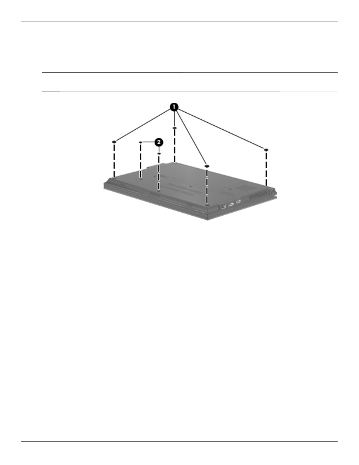
Computer feet
The computer feet are adhesive-backed rubber pads. The feet are included in the Rubber Feet Kit, spare part
number 581101-001. There are 6 rubber feet that attach to the base enclosure in the locations shown in the
following illustration.
The four rubber feet 1 in the corners of the computer are larger than the two rubber feet 2 in the middle of
✎
the computer.
4–6 Maintenance and Service Guide
Page 42
Battery
Removal and replacement procedures
Description Spare part number
4-cell, 41-WHr, 2.8-Ah battery 580956-001
6-cell, 62-WHr, 2.8-Ah battery (supports HP Fast Charge technology) 594796-001
Before removing the battery, follow these steps:
1. Shut down the computer. If you are unsure whether the computer is off or in Hibernation, turn the computer on,
and then shut it down through the operating system.
2. Disconnect all external devices connected to the computer.
3. Disconnect the power from the computer by first unplugging the power cord from the AC outlet, and then
unplugging the AC adapter from the computer.
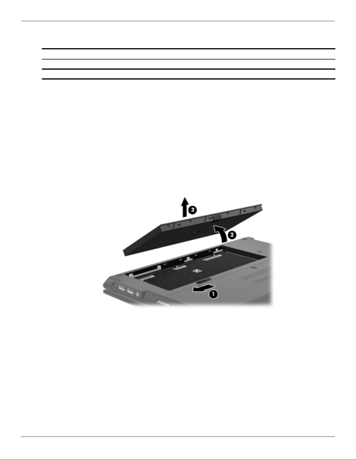
Remove the battery:
1. Turn the computer upside down on a flat surface, with the front toward you.
2. Slide the battery release latch 1 to release the battery.
3. Pivot the front edge of the battery 2 upward.
4. Remove the battery 3.
Install the battery by inserting it into the battery bay and pivoting it downward until it is seated. The battery release
latch automatically locks the battery into place.
Maintenance and Service Guide 4–7
Page 43

Removal and replacement procedures
SIM
The SIM is provided by the end user as a security measure for the WWAN module. The SIM should be removed,
✎
placed into a static-dissipative container, and then replaced when the computer is reassembled.
Before removing the SIM, follow these steps:
1. Shut down the computer. If you are unsure whether the computer is off or in Hibernation, turn the computer on,
and then shut it down through the operating system.
2. Disconnect all external devices connected to the computer.
3. Disconnect the power from the computer by first unplugging the power cord from the AC outlet, and then
unplugging the AC adapter from the computer.
4. Remove the battery (see “Battery” on page 4-7).
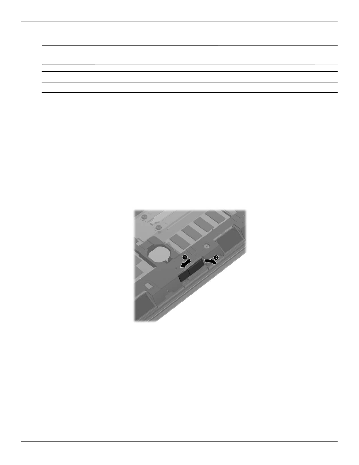
Remove the SIM:
1. Press in on the SIM 1 to release it from the SIM slot.
2. Remove the SIM 2 from the SIM slot.
Install the SIM by inserting it into the SIM slot until you hear a click.
4–8 Maintenance and Service Guide
Page 44

Mass storage device
The mass storage device spare part kit includes a bracket.
✎
Description Spare part number
Hard drive:
500-GB, 7200 rpm 618829-001
320-GB, 7200 rpm 581084-001
250-GB, 7200 rpm 581083-001
Solid-state drive (only with computer models running Windows 7 operating system, either 2 GB or 4 GB):
128-GB 581085-001
80-GB 581086-001
Before removing the mass storage device, follow these steps:
1. Shut down the computer. If you are unsure whether the computer is off or in Hibernation, turn the computer on,
and then shut it down through the operating system.
2. Disconnect all external devices connected to the computer.
Removal and replacement procedures
3. Disconnect the power from the computer by first unplugging the power cord from the AC outlet, and then
unplugging the AC adapter from the computer.
4. Remove the battery (see “Battery” on page 4-7).
Remove the mass storage device:
1. Position the computer with the front toward you.
2. Loosen the two Phillips PM2.5×6.0 captive screws that secure the accessory cover to the computer.
3. Slide the rear edge 1 of the accessory cover to detach it from the computer.
4. Remove the accessory cover 2. The accessory cover is included in the Plastics Kit, spare part number
618835-001.
Maintenance and Service Guide 4–9
Page 45
Removal and replacement procedures
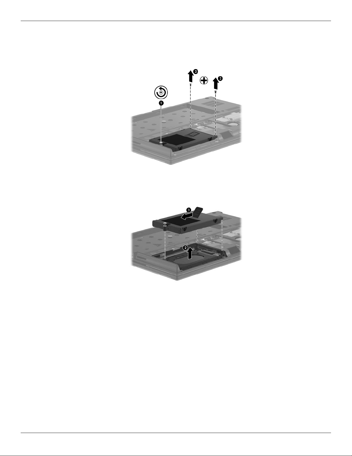
5. Loosen the Phillips PM2.5×11.0 captive screw 1 that secures the mass storage device in the mass storage
device bay.
6. Remove the two Phillips PM2.5×4.0 screws 2 that secure the mass storage device in the mass storage
device bay.
7. Grasp the Mylar tab 1 on the mass storage device bracket, and slide the mass storage device to the left 2 to
disconnect it from the system board.
8. Remove the mass storage device 3 from the mass storage device bay.
4–10 Maintenance and Service Guide
Page 46
Removal and replacement procedures
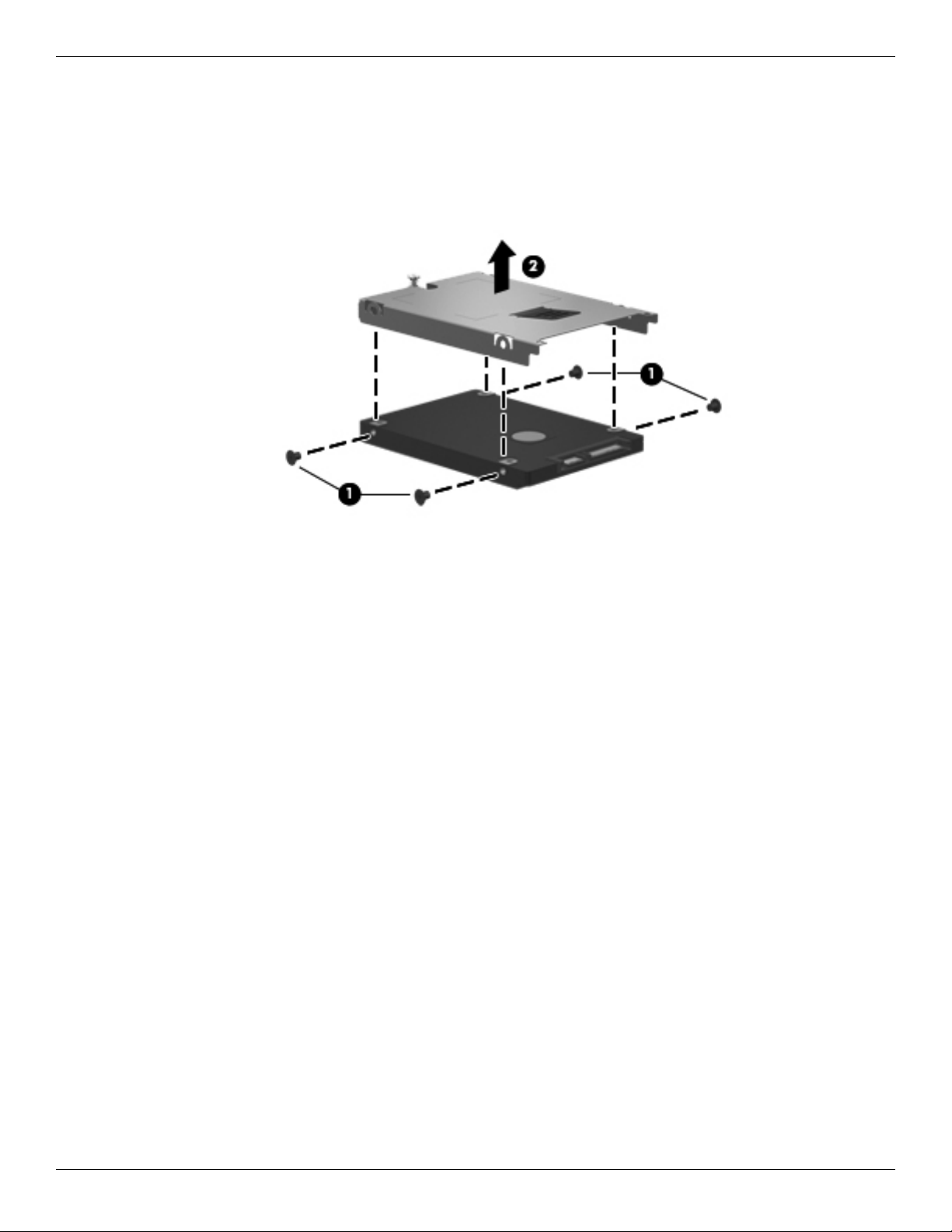
9. If it is necessary to replace the mass storage device bracket, follow these steps:
a. Remove the four Phillips PM3.0×4.0 screws 1 that secure the mass storage device bracket to the mass
storage device.
b. Lift the bracket 2 straight up to remove it from the mass storage device.
Reverse this procedure to reassemble and install the mass storage device.
Maintenance and Service Guide 4–11
Page 47
Removal and replacement procedures
Bluetooth module
The Bluetooth module spare part kit does not include a Bluetooth module cable. The Bluetooth module cable is
✎
included in the Cable Kit, spare part number 618826-001.
Description Spare part number
Bluetooth module
Before removing the Bluetooth module, follow these steps:
1. Shut down the computer. If you are unsure whether the computer is off or in Hibernation, turn the computer on,
and then shut it down through the operating system.
2. Disconnect all external devices connected to the computer.
3. Disconnect the power from the computer by first unplugging the power cord from the AC outlet, and then
unplugging the AC adapter from the computer.
4. Remove the battery (see “Battery” on page 4-7).
5. Remove the accessory cover (see “Mass storage device” on page 4-9).
Remove the Bluetooth module:
1. Release the Bluetooth module 1 by sliding it to the left until the right side of the module is clear of the opening
in the base enclosure, and then swinging the right side of the module 2 away from the base enclosure.
537921-001
4–12 Maintenance and Service Guide
Page 48

2. Disconnect the Bluetooth module cable from the Bluetooth module.
3. Remove the Bluetooth module.
Reverse this procedure to install the Bluetooth module.
Removal and replacement procedures
Maintenance and Service Guide 4–13
Page 49

Removal and replacement procedures
WLAN module
Description Spare part number
802.11 a/b/g/n WLAN module:
Broadcom 43224 802.11 a/b/g/n WLAN module for use in Antigua and Barbuda, Barbados, Belize,
Canada, the Cayman Islands, Guam, Puerto Rico, Trinidad and Tobago, the U.S. Virgin Islands,
and the United States
Broadcom 43224 802.11 a/b/g/n WLAN module for use in Afghanistan, Albania, Algeria, Andorra,
Angola, Argentina, Armenia, Aruba, Australia, Austria, Azerbaijan, the Bahamas, Bahrain,
Bangladesh, Barbados, Belarus, Belgium, Belize, Benin, Bermuda, Bhutan, Bolivia,
Bosnia and Herzegovina, Botswana, Brazil, the British Virgin Islands, Brunei, Bulgaria,
Burkina Faso, Burundi, Cambodia, Cameroon, Cape Verde, the Central African Republic, Chad,
Chile, Colombia, Comoros, the Congo, Costa Rica, Croatia, Cyprus, the Czech Republic, Denmark,
Djibouti, Dominica, the Dominican Republic, East Timor, Ecuador, Egypt, El Salvador,
Equatorial Guinea, Eritrea, Estonia, Ethiopia, Fiji, Finland, France, French Guiana, Gabon, Gambia,
Georgia, Germany, Ghana, Gibraltar, Greece, Grenada, Guadeloupe, Guatemala, Guinea,
Guinea-Bissau, Guyana, Haiti, Honduras, Hong Kong, Hungary, Iceland, India, Indonesia, Ireland,
Italy, the Ivory Coast, Jamaica, Japan, Jordan, Kazakhstan, Kenya, Kiribati, Kuwait, Kyrgyzstan,
Laos, Latvia, Lebanon, Lesotho, Liberia, Liechtenstein, Lithuania, Luxembourg, Macedonia,
Madagascar, Malawi, Malaysia, the Maldives, Mali, Malta, the Marshall Islands, Martinique,
Mauritania, Mauritius, Mexico, Micronesia, Monaco, Mongolia, Montenegro, Morocco, Mozambique,
Namibia, Nauru, Nepal, the Nether Antilles, the Netherlands, New Zealand, Nicaragua, Niger,
Nigeria, Norway, Oman, Pakistan, Palau, Panama, Papua New Guinea, Paraguay,
the People’s Republic of China, Peru, the Philippines, Poland, Portugal, Qatar,
the Republic of Moldova, Romania, Russia, Rwanda, Samoa, San Marino, Sao Tome and Principe,
Saudi Arabia, Senegal, Serbia, the Seychelles, Sierra Leone, Singapore, Slovakia, Slovenia,
the Solomon Islands, Somalia, South Africa, South Korea, Spain, Sri Lanka, St. Kitts and Nevis,
St. Lucia, St. Vincent, Suriname, Swaziland, Sweden, Switzerland, Taiwan, Tajikistan, Tanzania,
Thailand, Togo, Tonga, Tunisia, Turkey, Turkmenistan, Tuvalu, Uganda, Ukraine,
the United Arab Emirates, the United Kingdom, Uruguay, Uzbekistan, Vanuatu, Venezuela, Vietnam,
Yemen, Zaire, Zambia, and Zimbabwe
582564-001
582564-002
802.11 b/g/n WLAN module:
Broadcom 4312G 802.11 b/g/n WLAN module for use in Canada, the Cayman Islands, Guam,
Puerto Rico, the United States, and the U.S. Virgin Islands
593836-001
Before removing the WLAN module, follow these steps:
1. Shut down the computer. If you are unsure whether the computer is off or in Hibernation, turn the computer on,
and then shut it down through the operating system.
2. Disconnect all external devices connected to the computer.
3. Disconnect the power from the computer by first unplugging the power cord from the AC outlet, and then
unplugging the AC adapter from the computer.
4. Remove the battery (see “Battery” on page 4-7).
5. Remove the accessory cover (see “Mass storage device” on page 4-9).
4–14 Maintenance and Service Guide
Page 50

Removal and replacement procedures
Remove the WLAN module:
CAUTION: To prevent an unresponsive system, replace the wireless module only with a wireless module authorized for use in the
Ä
computer by the governmental agency that regulates wireless devices in your country or region. If you replace the module and
then receive a warning message, remove the module to restore computer functionality, and then contact technical support through
Help and Support.
1. Position the computer with the front toward you.
2. Disconnect the WLAN antenna cables from the terminals on the WLAN module.
The black WLAN antenna cable is connected to the WLAN module “Main” terminal. The white WLAN
✎
antenna cable is connected to the WLAN module “Aux” terminal.
3. Remove the Phillips PM2.5×4.0 screw that secures the WLAN module to the system board. (The WLAN
module tilts up.)
Maintenance and Service Guide 4–15
Page 51

Removal and replacement procedures
4. Remove the WLAN module by pulling it away from the slot at an angle.
WLAN modules are designed with a notch to prevent incorrect insertion of the WLAN module into the
✎
WLAN module slot.
If the WLAN antennas are not connected to the terminals on the WLAN module, the protective sleeves must be
✎
installed on the antenna connectors, as shown in the following illustration.
Reverse this procedure to install the WLAN module.
4–16 Maintenance and Service Guide
Page 52

WWAN module
Description Spare part number
Removal and replacement procedures
UNDP HSPA EV-DO WWAN module (does not support Linux operating system; available in all
countries and regions, except China)
Before removing the WWAN module, follow these steps:
1. Shut down the computer. If you are unsure whether the computer is off or in Hibernation, turn the computer on,
and then shut it down through the operating system.
2. Disconnect all external devices connected to the computer.
3. Disconnect the power from the computer by first unplugging the power cord from the AC outlet, and then
unplugging the AC adapter from the computer.
4. Remove the battery (see “Battery” on page 4-7).
5. Remove the accessory cover (see “Mass storage device” on page 4-9).
Remove the WWAN module:
CAUTION: To prevent an unresponsive system, replace the wireless module only with a wireless module authorized for use in the
Ä
computer by the governmental agency that regulates wireless devices in your country or region. If you replace the module and
then receive a warning message, remove the module to restore computer functionality, and then contact technical support through
Help and Support.
1. Position the computer with the front toward you.
2. Disconnect the WWAN antenna cables from the terminals on the WWAN module.
The red WWAN antenna cable is connected to the WWAN module “Main” terminal. The blue WWAN
✎
antenna cable is connected to the WWAN module “Aux” terminal.
531993-001
Maintenance and Service Guide 4–17
Page 53

Removal and replacement procedures
3. Remove the Phillips PM2.5×4.0 screw that secures the WWAN module to the system board. (The WWAN
module tilts up.)
4. Remove the WWAN module by pulling it away from the slot at an angle.
WWAN modules are designed with a notch to prevent incorrect insertion of the WWAN module into the
✎
WWAN module slot.
4–18 Maintenance and Service Guide
Page 54

Removal and replacement procedures
If the WWAN antennas are not connected to the terminals on the WWAN module, the protective sleeves must be
✎
installed on the antenna connectors, as shown in the following illustration.
Reverse this procedure to install the WWAN module.
Maintenance and Service Guide 4–19
Page 55

Removal and replacement procedures
RTC battery
Description Spare part number
RTC battery (includes double-sided tape) 481089-001
Before removing the RTC battery, follow these steps:
1. Shut down the computer. If you are unsure whether the computer is off or in Hibernation, turn the computer on,
and then shut it down through the operating system.
2. Disconnect all external devices connected to the computer.
3. Disconnect the power from the computer by first unplugging the power cord from the AC outlet, and then
unplugging the AC adapter from the computer.
4. Remove the battery (see “Battery” on page 4-7).
5. Remove the accessory cover (see “Mass storage device” on page 4-9).
Remove the RTC battery:
1. Disconnect the RTC battery cable 1 from the system board.
2. Detach the RTC battery 2 from the system board. (The RTC battery is attached to the system board with
double-sided tape.)
Reverse this procedure to install the RTC battery.
4–20 Maintenance and Service Guide
Page 56

Memory module
Description Spare part number
4096-MB memory module (1333-MHz, DDR3, PC3-10600 Shared) 599092-001
2048-MB memory module (1333-MHz, DDR3, PC3-10600) 581096-001
1024-MB memory module (1333-MHz, DDR3, PC3-10600 Shared) (not available on Microsoft 64-bit
operating systems)
Before removing the memory module, follow these steps:
1. Shut down the computer. If you are unsure whether the computer is off or in Hibernation, turn the computer on,
and then shut it down through the operating system.
2. Disconnect all external devices connected to the computer.
3. Disconnect the power from the computer by first unplugging the power cord from the AC outlet, and then
unplugging the AC adapter from the computer.
4. Remove the battery (see “Battery” on page 4-7).
5. Remove the accessory cover (see “Mass storage device” on page 4-9).
Remove the memory module:
1. Pull away the retention clips on each side of the memory module to release the memory module. (The memory
module tilts up.)
Removal and replacement procedures
598859-001
Maintenance and Service Guide 4–21
Page 57
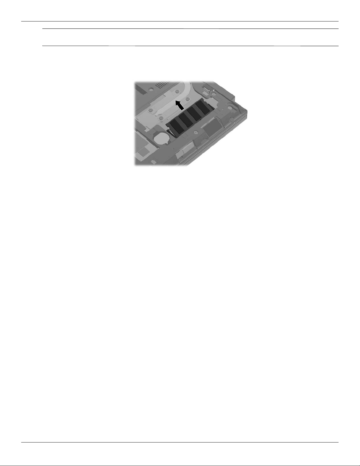
Removal and replacement procedures
CAUTION: To prevent damage to the memory module, hold it by the edges only. Do not touch the components on the memory
Ä
module.
2. Grasp the edge of the memory module, and then pull it out of the memory module slot.
Memory modules are designed with a notch to prevent incorrect insertion into the memory module slot.
✎
Reverse this procedure to install a memory module.
4–22 Maintenance and Service Guide
Page 58

Keyboard
The keyboard spare part kit includes a keyboard cable.
✎
Removal and replacement procedures
Keyboard for use in country
or region
Belgium 618843-A41 Norway 618843-091
Bulgaria 618843-261 Portugal 618843-131
The Czech Republic and Slovakia 618843-A81 Russia 618843-251
Denmark 618843-081 Saudi Arabia 618843-171
France 618843-051 Slovenia 618843-BA1
France and Arabia 618843_DW1 South Korea 618843-AD1
French Canada 618843-121 Spain 618843-071
Germany 618843-041 Sweden and Finland 618843-B71
Greece 618843-DJ1 Switzerland 618843-BG1
Hungary 618843-211 Taiwan 618843-AB1
Iceland 618843-DD1 Thailand 618843-281
Israel 618843-BB1 Turkey 618843-141
Italy 618843-061 The United Kingdom 618843-031
Japan 618843-291 The United States 618843-001
The Netherlands 618843-B31
Spare part number
Keyboard for use in country
or region Spare part number
Before removing the keyboard, follow these steps:
1. Shut down the computer. If you are unsure whether the computer is off or in Hibernation, turn the computer on,
and then shut it down through the operating system.
2. Disconnect all external devices connected to the computer.
3. Disconnect the power from the computer by first unplugging the power cord from the AC outlet, and then
unplugging the AC adapter from the computer.
4. Remove the battery (see “Battery” on page 4-7).
5. Remove the accessory cover (see “Mass storage device” on page 4-9).
Maintenance and Service Guide 4–23
Page 59

Removal and replacement procedures
Remove the keyboard:
1. Position the computer with the front toward you.
2. Remove the following screws:
❏ Two To r x T8 M 2.5 ×5. 0 scr e w s 1 in the mass storage device bay and the wireless module compartment
❏ One Phillips PM2.5×2.0 broadhead screw 2 in the battery bay
3. Turn the computer display-side up, with the front toward you.
4. Open the computer as far as possible.
5. Slide the keyboard 1 back until it rests on the display.
6. Lift the rear edge of the keyboard 2 until it rests at an angle.
4–24 Maintenance and Service Guide
Page 60
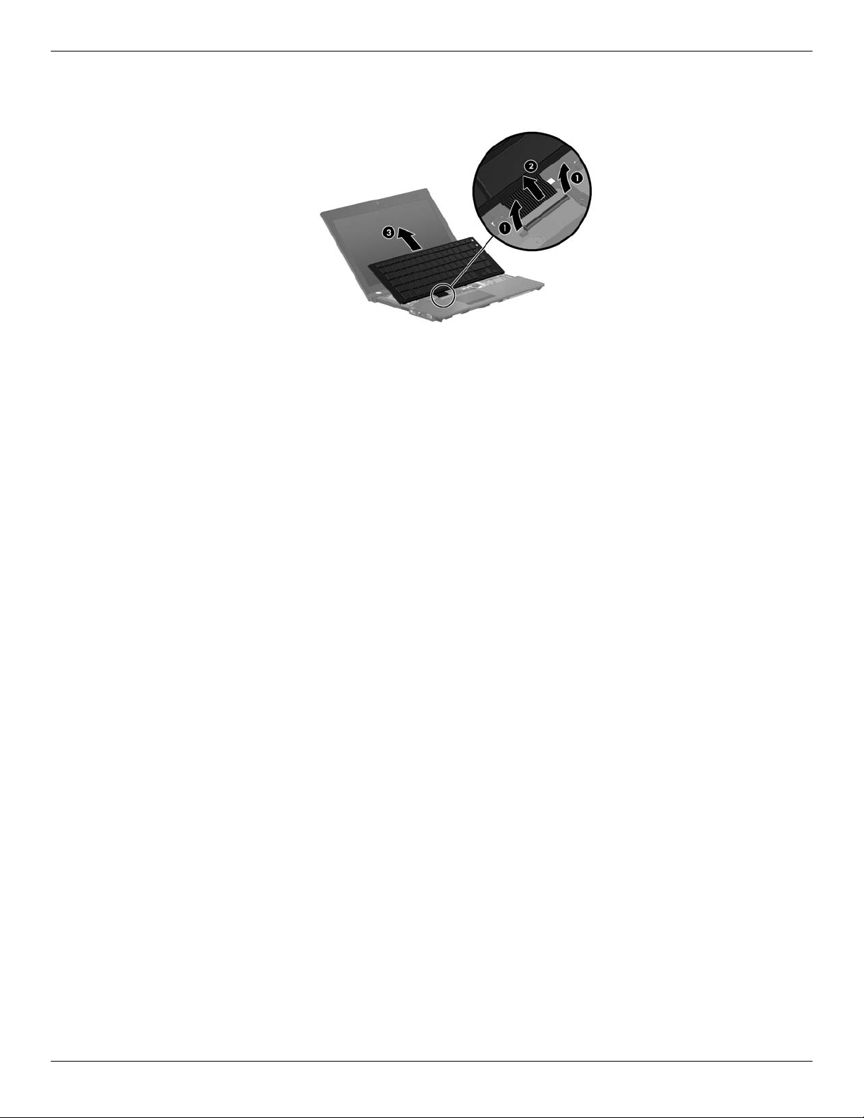
Removal and replacement procedures
7. Release the zero insertion force (ZIF) connector 1 to which the keyboard cable is attached, disconnect the
keyboard cable 2 from the system board, and then remove the keyboard 3.
Reverse this procedure to install the keyboard.
Maintenance and Service Guide 4–25
Page 61
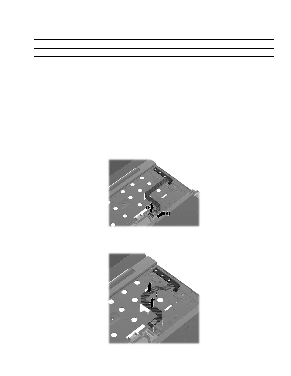
Removal and replacement procedures
Button board and cable
Description Spare part number
Button board with FFC (includes cable) 618815-001
Before removing the button board and cable, follow these steps:
1. Shut down the computer. If you are unsure whether the computer is off or in Hibernation, turn the computer on,
and then shut it down through the operating system.
2. Disconnect all external devices connected to the computer.
3. Disconnect the power from the computer by first unplugging the power cord from the AC outlet, and then
unplugging the AC adapter from the computer.
4. Remove the battery (see “Battery” on page 4-7).
5. Remove the accessory cover (see “Mass storage device” on page 4-9).
6. Remove the keyboard (see “Keyboard” on page 4-23).
Remove the button board and cable:
1. Release the ZIF connector 1 to which the button board cable is attached, and then disconnect the button board
cable 2 from the system board.
2. Release the button board cable from the top cover. (The button board cable is attached to the top cover with
double-sided tape.)
4–26 Maintenance and Service Guide
Page 62
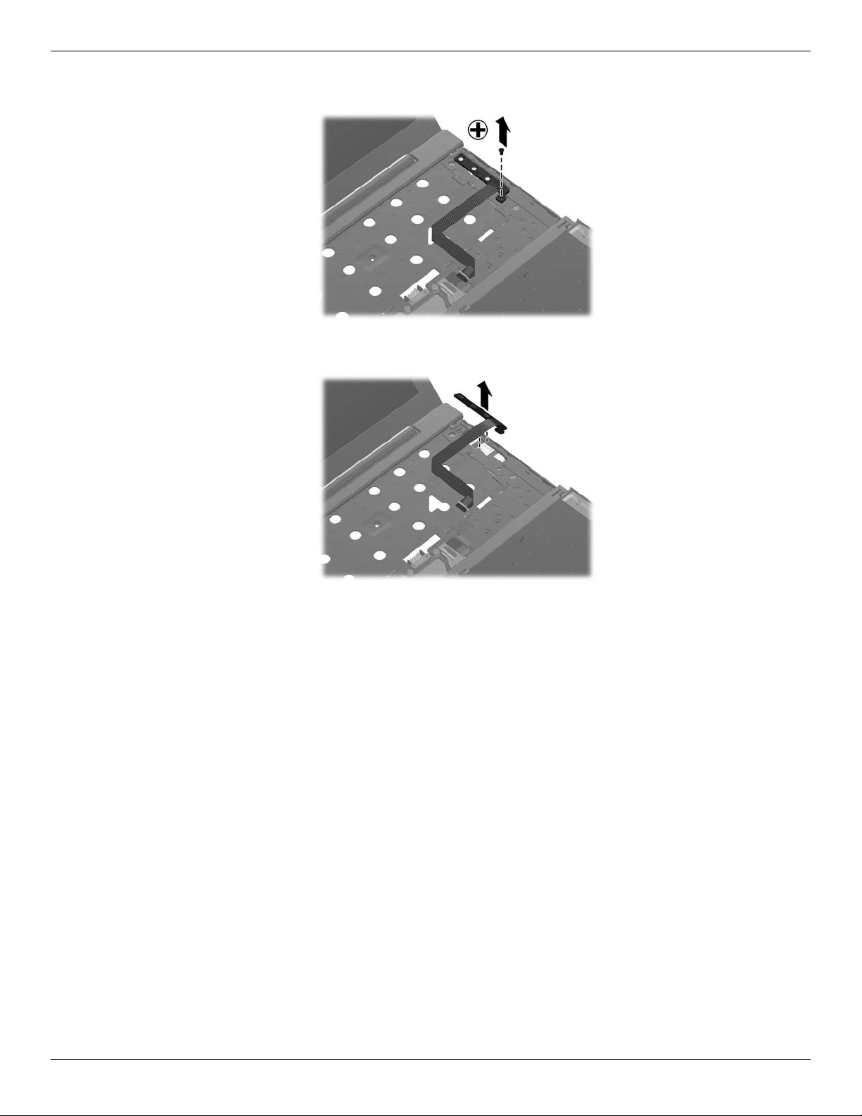
Removal and replacement procedures
3. Remove the Torx T8M2.5×4.0 screw that secures the button board to the top cover.
4. Lift the button board to release it from the clips built into the top cover.
5. Remove the button board and cable.
Reverse this procedure to install the button board and cable.
Maintenance and Service Guide 4–27
Page 63
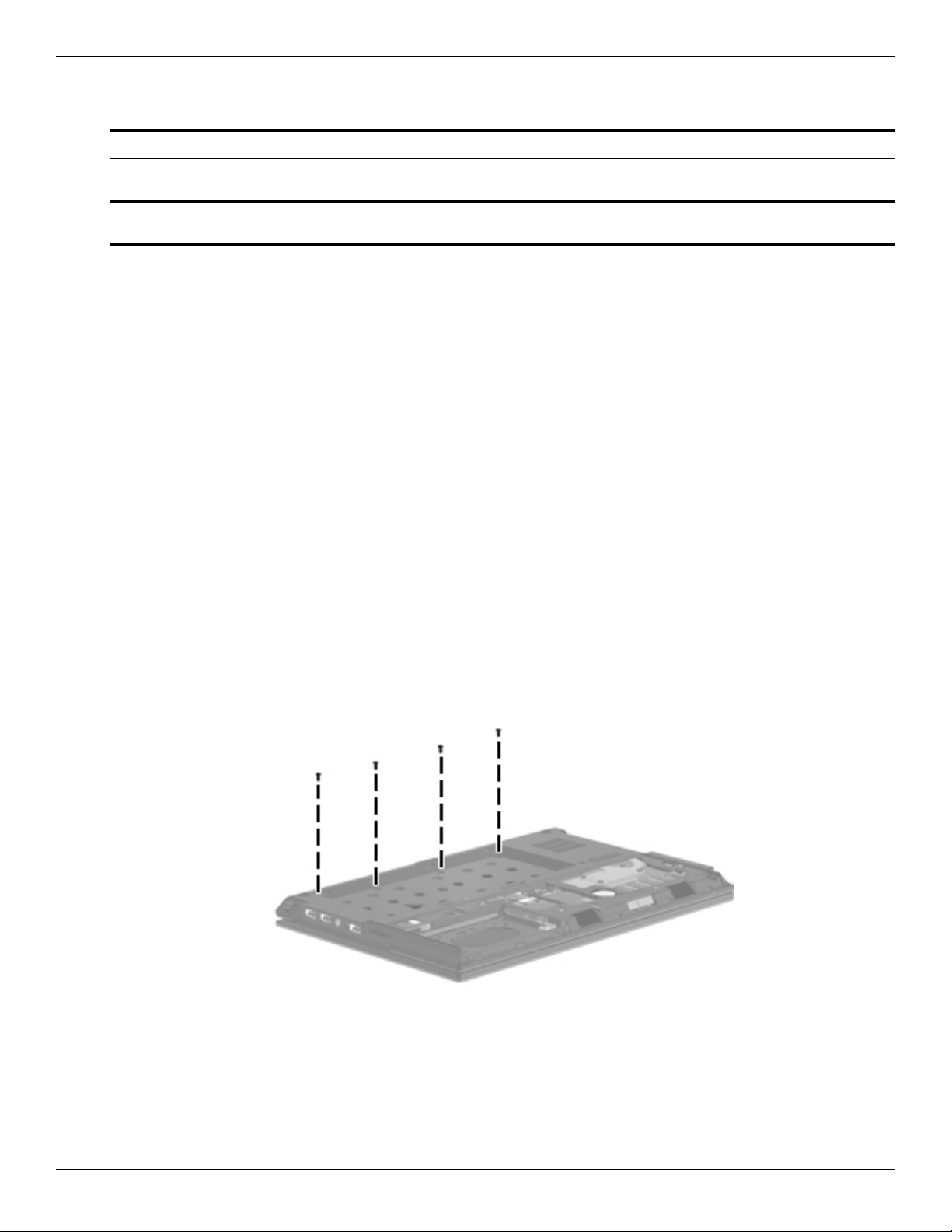
Removal and replacement procedures
Top cover
Description Spare part number
Top cover with fingerprint reader (includes TouchPad button board and cable, and TouchPad board
and cable)
Top cover with no fingerprint reader (includes TouchPad button board and cable, and TouchPad
board and cable)
618840-001
618841-001
Before removing the top cover, follow these steps:
1. Shut down the computer. If you are unsure whether the computer is off or in Hibernation, turn the computer on,
and then shut it down through the operating system.
2. Disconnect all external devices connected to the computer.
3. Disconnect the power from the computer by first unplugging the power cord from the AC outlet, and then
unplugging the AC adapter from the computer.
4. Remove the battery (see “Battery” on page 4-7).
5. Remove the following components:
a. Accessory cover (see “Mass storage device” on page 4-9)
b. Keyboard (see “Keyboard” on page 4-23)
c. Button board and cable (see “Button board and cable” on page 4-26)
Remove the top cover:
1. Turn the computer upside down, with the front toward you.
2. Remove the following screws:
❏ Three Torx T8M2.5×5.0 screws 1 in the battery bay
❏ Three Torx T8M2.5×6.0 screws 2 in the mass storage device bay
❏ Two To r x T8 M 2.5 ×9. 0 scr e w s 3 in the RTC battery compartment
4–28 Maintenance and Service Guide
Page 64

Removal and replacement procedures
3. Turn the computer display-side up, with the front toward you.
4. Open the computer as far as possible.
5. Release the ZIF connector 1 to which the power button board cable is attached, and then disconnect the power
button board cable from the system board.
6. Release the ZIF connector 2 to which the TouchPad cable is attached, and then disconnect the TouchPad cable
from the system board.
7. Remove the seven slotted Torx T8M2.5×7.0 screws that secure the top cover to the base enclosure.
Maintenance and Service Guide 4–29
Page 65
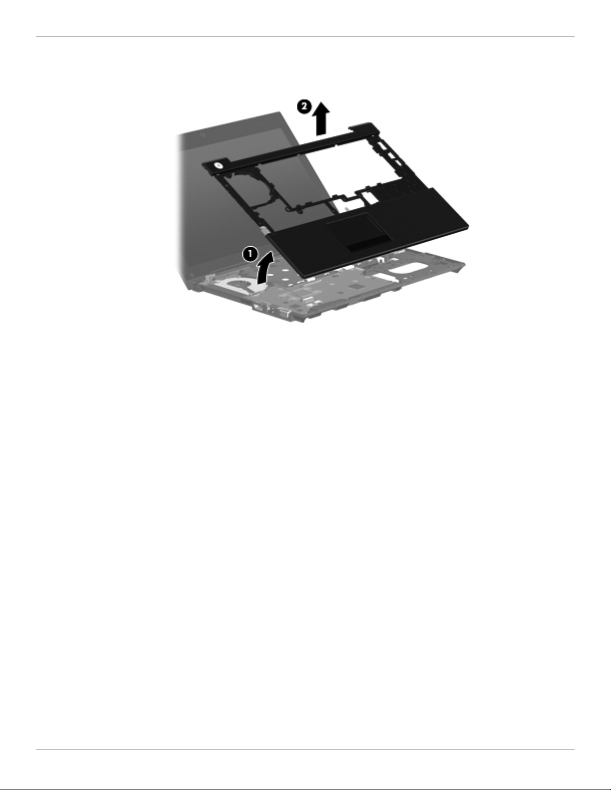
Removal and replacement procedures
8. Lift the rear edge 1 of the top cover until it detaches from the base enclosure.
9. Remove the top cover 2 by lifting it straight up.
Reverse this procedure to install the top cover.
4–30 Maintenance and Service Guide
Page 66

Power button board and cable
Description Spare part number
Power button board with FFC (includes cable) 618816-001
Before removing the power button board and cable, follow these steps:
1. Shut down the computer. If you are unsure whether the computer is off or in Hibernation, turn the computer on,
and then shut it down through the operating system.
2. Disconnect all external devices connected to the computer.
3. Disconnect the power from the computer by first unplugging the power cord from the AC outlet, and then
unplugging the AC adapter from the computer.
4. Remove the battery (see “Battery” on page 4-7).
5. Remove the following components:
a. Accessory cover (see “Mass storage device” on page 4-9)
b. Keyboard (see “Keyboard” on page 4-23)
c. Button board and cable (see “Button board and cable” on page 4-26)
d. Top cover (see “Top cover” on page 4-28)
Removal and replacement procedures
Remove the power button board and cable:
1. Release the ZIF connector 1 to which the power button board cable is attached, and then disconnect the cable
from the system board.
2. Disconnect the power cable 2 from the system board.
3. Remove the two Torx T8M2.5×6.0 screws 3 that secure the power button board to the base enclosure.
4. Remove the power button board and cable 4 by lifting them straight up.
Reverse this procedure to install the power button board and cable.
Maintenance and Service Guide 4–31
Page 67

Removal and replacement procedures
Bluetooth module cable
The Bluetooth module cable is included in the Cable Kit, spare part number 618826-001.
✎
Before removing the Bluetooth module cable, follow these steps:
1. Shut down the computer. If you are unsure whether the computer is off or in Hibernation, turn the computer on,
and then shut it down through the operating system.
2. Disconnect all external devices connected to the computer.
3. Disconnect the power from the computer by first unplugging the power cord from the AC outlet, and then
unplugging the AC adapter from the computer.
4. Remove the battery (see “Battery” on page 4-7).
5. Remove the following components:
a. Accessory cover (see “Mass storage device” on page 4-9)
b. Keyboard (see “Keyboard” on page 4-23)
c. Button board and cable (see “Button board and cable” on page 4-26)
d. Top cover (see “Top cover” on page 4-28)
Remove the Bluetooth module cable:
1. Disconnect the Bluetooth module cable 1 from the system board.
2. Remove the Bluetooth module cable 2.
Reverse this procedure to install the Bluetooth module cable.
4–32 Maintenance and Service Guide
Page 68

System board
The system board spare part kit includes a processor and replacement thermal material.
✎
Description Spare part number
Removal and replacement procedures
Intel® Dual Core i5-45M 2.40-GHz processor (Turbo up to 2.53 GHz), 3-M L3 cache, 4 threads
(35W)
Intel® Dual Core i5-45M 2.40-GHz processor (Turbo up to 2.53 GHz), 3-M L3 cache, 4 threads
(35W), for use in China and Russia
Intel Dual Core i3-370M 2.40-GHz processor, 3-M L3 cache, 4 threads (35W) 618819-001
Intel Dual Core i3-370M 2.40-GHz processor, 3-M L3 cache, 4 threads (35W), for use in China and
Russia
Intel Dual Core i3-350M 2.26-GHz processor, 3-M L3 cache, 4 threads (35W) 618817-001
Intel Dual Core i3-350M 2.26-GHz processor, 3-M L3 cache, 4 threads (35W), for use in China and
Russia
Intel U3400 1.06-GHz processor 618823-001
Intel U3400 1.06-GHz processor, for use in China and Russia 618824-001
618821-001
618822-001
618820-001
618818-001
Before removing the system board, follow these steps:
1. Shut down the computer. If you are unsure whether the computer is off or in Hibernation, turn the computer on,
and then shut it down through the operating system.
2. Disconnect all external devices connected to the computer.
3. Disconnect the power from the computer by first unplugging the power cord from the AC outlet, and then
unplugging the AC adapter from the computer.
4. Remove the battery (see “Battery” on page 4-7).
5. Remove the following components:
a. Accessory cover (see “Mass storage device” on page 4-9)
b. Keyboard (see “Keyboard” on page 4-23)
c. Button board and cable (see “Button board and cable” on page 4-26)
d. Top cover (see “Top cover” on page 4-28)
When replacing the system board, be sure that the following additional components are removed from the defective
system board and installed on the replacement system board:
■ SIM (see “SIM” on page 4-8)
■ Bluetooth module (see “Bluetooth module” on page 4-12)
■ WLAN module (see “WLAN module” on page 4-14)
■ WWAN module (see “WWAN module” on page 4-17)
■ RTC battery (see “RTC battery” on page 4-20)
■ Memory module (see “Memory module” on page 4-21)
■ Bluetooth module cable (see “Bluetooth module cable” on page 4-32)
■ Fan and heat sink (see “Fan and heat sink” on page 4-36)
Maintenance and Service Guide 4–33
Page 69
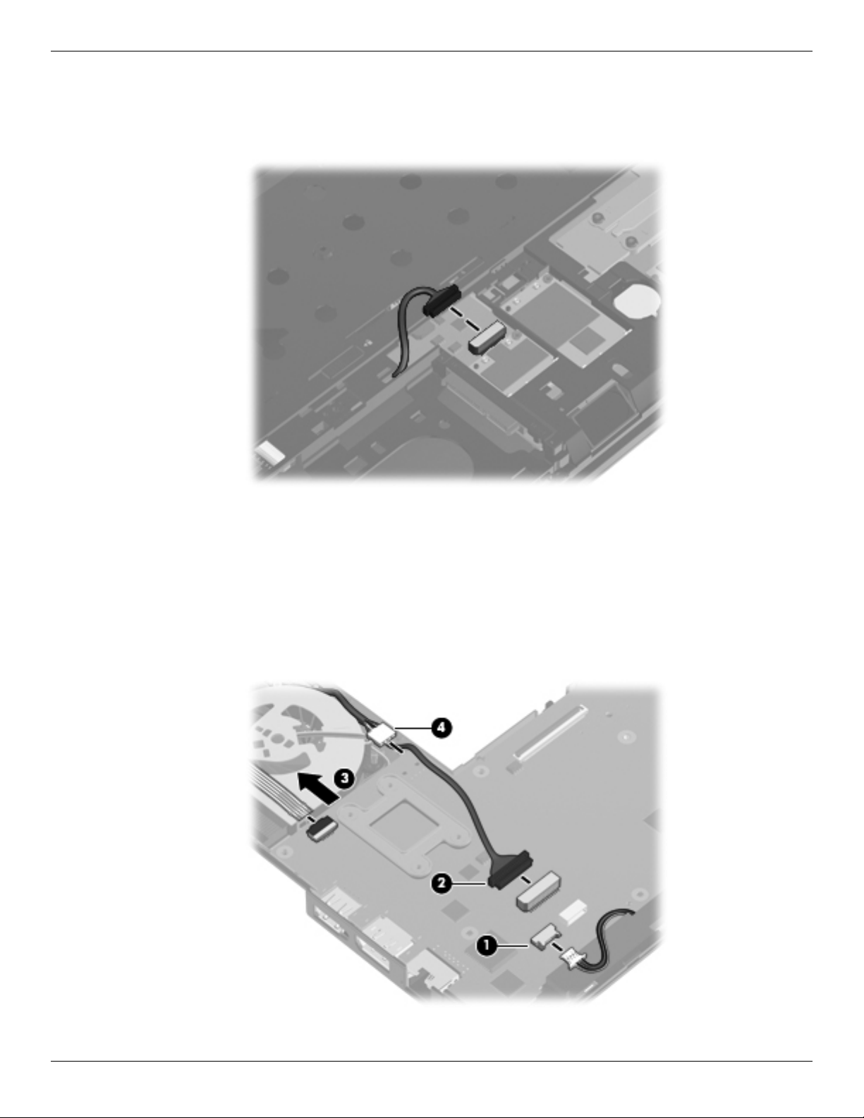
Removal and replacement procedures
Remove the system board:
1. Turn the computer upside down, with the front toward you.
2. Disconnect the SD Card Reader board cable from the system board.
3. Turn the computer display-side up, with the front toward you.
4. Open the computer as far as possible.
5. Disconnect the speaker cable 1 from the system board.
6. Disconnect the display panel cable 2 from the system board.
7. Release the ZIF connector 3 to which the power button board board cable is attached, and then disconnect the
cable from the system board.
8. Disconnect the power cable 4 from the system board.
4–34 Maintenance and Service Guide
Page 70

Removal and replacement procedures
9. Remove the three Torx T8M2.5×4.0 screws that secure the system board to the base enclosure.
10. Lift the left side of the system board 1 until it rests at an angle.
11. Remove the system board 2 by sliding it away from the base enclosure at an angle.
Reverse this procedure to install the system board.
Maintenance and Service Guide 4–35
Page 71

Removal and replacement procedures
Fan and heat sink
The fan and heat sink spare part kit includes replacement thermal material.
✎
Description Spare part number
Fan/Heat sink 618830-001
To properly ventilate the computer, allow at least 7.6 cm (3 in) of clearance on the left side of the computer. The
✎
computer uses an electric fan for ventilation. The fan is controlled by a temperature sensor and is designed to
turn on automatically when high temperature conditions exist. These conditions are affected by high external
temperatures, system power consumption, power management/battery conservation configurations, battery fast
charging, and software requirements. Exhaust air is displaced through the ventilation grill located on the left side
of the computer.
Before removing the fan and heat sink, follow these steps:
1. Shut down the computer. If you are unsure whether the computer is off or in Hibernation, turn the computer on,
and then shut it down through the operating system.
2. Disconnect all external devices connected to the computer.
3. Disconnect the power from the computer by first unplugging the power cord from the AC outlet, and then
unplugging the AC adapter from the computer.
4. Remove the battery (see “Battery” on page 4-7).
5. Remove the following components:
a. Accessory cover (see “Mass storage device” on page 4-9)
b. Keyboard (see “Keyboard” on page 4-23)
c. Button board and cable (see “Button board and cable” on page 4-26)
d. Top cover (see “Top cover” on page 4-28)
e. System board (see “System board” on page 4-33)
4–36 Maintenance and Service Guide
Page 72

Removal and replacement procedures
Remove the fan and heat sink:
1. Turn the system board upside down, with the front toward you.
2. Disconnect the fan cable 1 from the system board.
3. Following the 1, 2, 3, 4 sequence stamped into the heat sink, loosen the four Torx T8M2.0×7.0 captive
screws 2 that secure the fan and heat sink to the system board.
Due to the adhesive quality of the thermal material located between the heat sink and system board
✎
components, it may be necessary to move the heat sink from side to side to detach it.
4. Remove the fan and heat sink 3.
Maintenance and Service Guide 4–37
Page 73
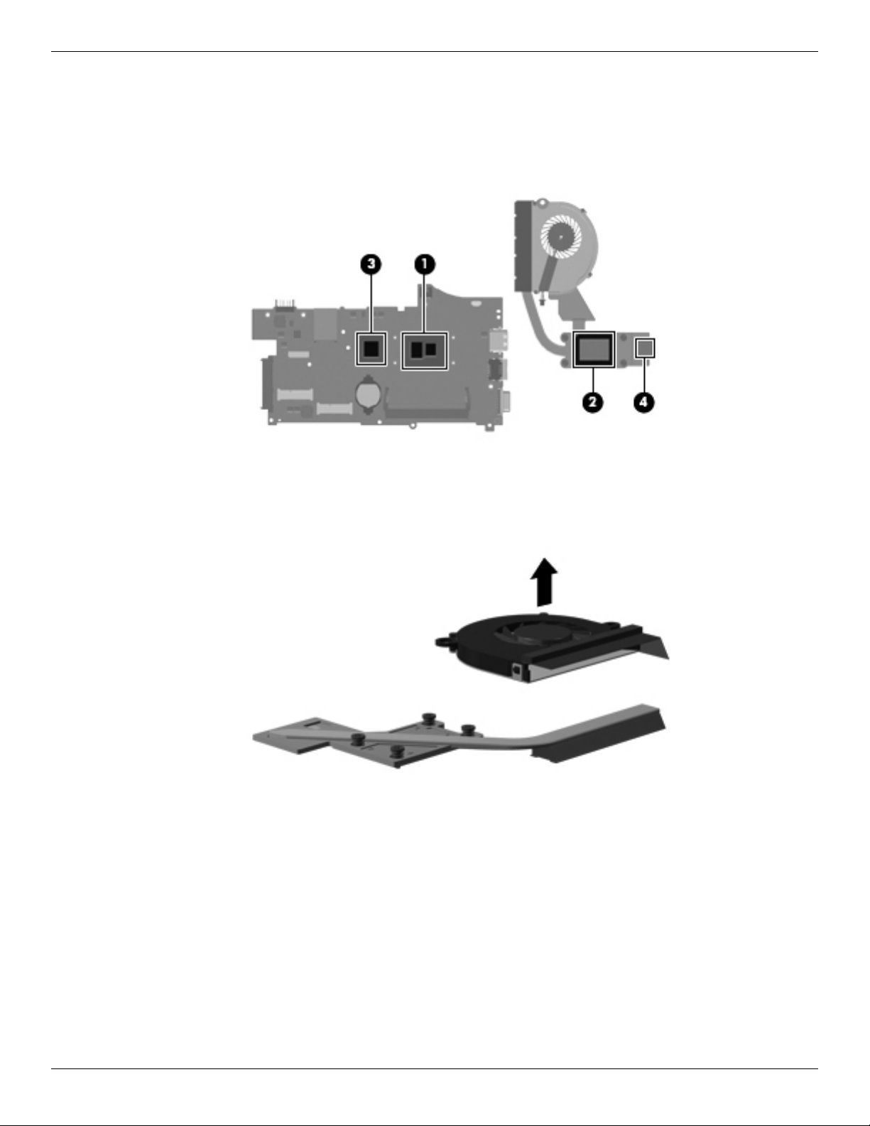
Removal and replacement procedures
The thermal material must be thoroughly cleaned from the surfaces of the heat sink and the system board
✎
each time the heat sink is removed:
❏ Thermal paste is used on the processor 1 and the heat sink section 2 that services it.
❏ Thermal pads are used on the Northbridge chip 3 and the heat sink section 4 that services it.
Replacement thermal material is included with all system board and heat sink spare part kits.
5. Lift the fan straight up to remove it from the heat sink. (The fan is attached to the heat sink with
double-sided tape.)
Reverse this procedure to install the fan and heat sink.
4–38 Maintenance and Service Guide
Page 74
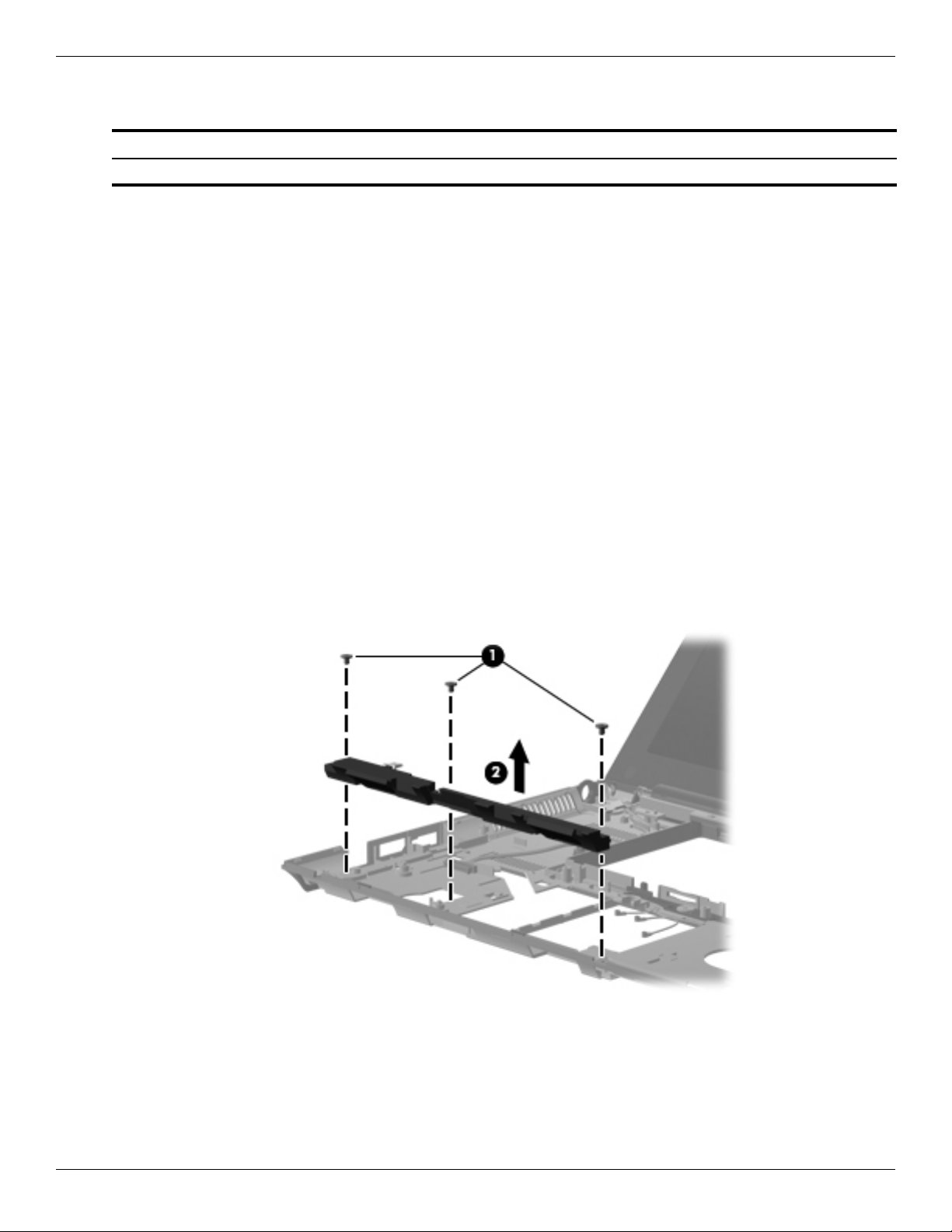
Speaker assembly
Description Spare part number
Speaker assembly (includes cable) 618839-001
Before removing the speaker assembly, follow these steps:
1. Shut down the computer. If you are unsure whether the computer is off or in Hibernation, turn the computer on,
and then shut it down through the operating system.
2. Disconnect all external devices connected to the computer.
3. Disconnect the power from the computer by first unplugging the power cord from the AC outlet, and then
unplugging the AC adapter from the computer.
4. Remove the battery (see “Battery” on page 4-7).
5. Remove the following components:
a. Accessory cover (see “Mass storage device” on page 4-9)
b. Keyboard (see “Keyboard” on page 4-23)
c. Button board and cable (see “Button board and cable” on page 4-26)
d. Top cover (see “Top cover” on page 4-28)
Removal and replacement procedures
e. System board (see “System board” on page 4-33)
Remove the speaker assembly:
1. Remove the three Torx T8M2.5×4.0 screws 1 that secure the speaker assembly to the base enclosure.
2. Remove the speaker assembly 2.
Reverse this procedure to install the speaker assembly.
Maintenance and Service Guide 4–39
Page 75

Removal and replacement procedures
USB board
Description Spare part number
USB board (includes cable) 618825-001
Before removing the USB board, follow these steps:
1. Shut down the computer. If you are unsure whether the computer is off or in Hibernation, turn the computer on,
and then shut it down through the operating system.
2. Disconnect all external devices connected to the computer.
3. Disconnect the power from the computer by first unplugging the power cord from the AC outlet, and then
unplugging the AC adapter from the computer.
4. Remove the battery (see “Battery” on page 4-7).
5. Remove the following components:
a. Accessory cover (see “Mass storage device” on page 4-9)
b. Keyboard (see “Keyboard” on page 4-23)
c. Button board and cable (see “Button board and cable” on page 4-26)
d. Top cover (see “Top cover” on page 4-28)
e. System board (see “System board” on page 4-33)
Remove the USB board:
1. Disconnect the microphone cable 1 from the USB board.
2. Remove the two Torx T8M2.5×4.0 screws 2 that secure the USB board to the base enclosure.
3. Remove the USB board 3 and cable.
Reverse this procedure to install the USB board.
4–40 Maintenance and Service Guide
Page 76
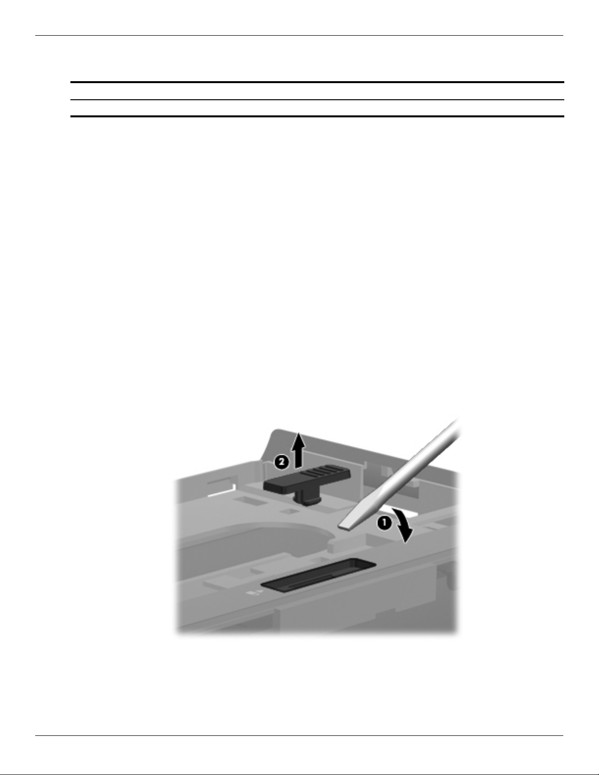
Battery eject arm
Description Spare part number
Latch Kit (includes battery eject arm, latch, and spring) 581090-001
Before removing the battery eject arm, follow these steps:
1. Shut down the computer. If you are unsure whether the computer is off or in Hibernation, turn the computer on,
and then shut it down through the operating system.
2. Disconnect all external devices connected to the computer.
3. Disconnect the power from the computer by first unplugging the power cord from the AC outlet, and then
unplugging the AC adapter from the computer.
4. Remove the battery (see “Battery” on page 4-7).
5. Remove the following components:
a. Accessory cover (see “Mass storage device” on page 4-9)
b. Keyboard (see “Keyboard” on page 4-23)
c. Button board and cable (see “Button board and cable” on page 4-26)
d. Top cover (see “Top cover” on page 4-28)
Removal and replacement procedures
e. System board (see “System board” on page 4-33)
Remove the battery eject arm:
1. Turn the base enclosure upside down, with the front toward you.
2. Use a flat-bladed screw driver 1 or similar tool to release the battery eject latch from the base enclosure.
3. Remove the the battery eject latch 2.
Maintenance and Service Guide 4–41
Page 77
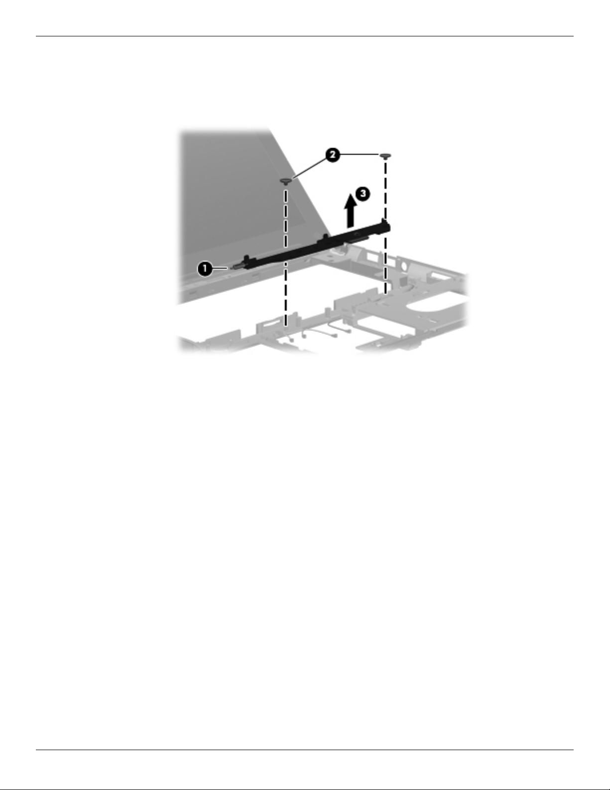
Removal and replacement procedures
4. Release the battery eject arm spring 1 from the tab built into the base enclosure.
5. Remove the two Phillips PM2.5×4.0 broadhead screws 2 that secure the battery eject arm to the
base enclosure.
6. Remove the the battery eject arm 3.
Reverse this procedure to install the battery eject arm.
4–42 Maintenance and Service Guide
Page 78
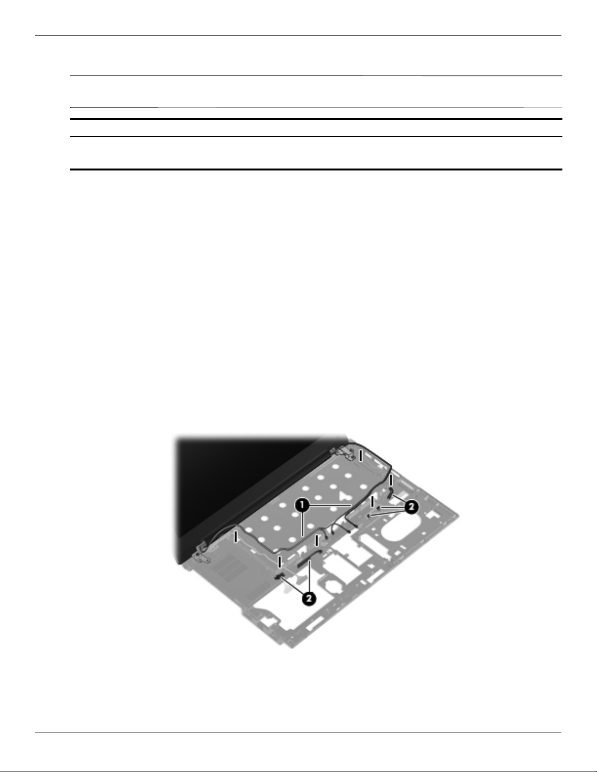
Display assembly
The display assembly spare part kit includes 2 WLAN antenna transceivers and cables, 2 WWAN antenna
✎
transceivers and cables, webcam, nameplate, and logo.
Description Spare part number
13.3-in, HD, LED, AntiGlare display assembly 618827-001
13.3-in, HD, LED, BrightView display assembly 618828-001
Before removing the display assembly, follow these steps:
1. Shut down the computer. If you are unsure whether the computer is off or in Hibernation, turn the computer on,
and then shut it down through the operating system.
2. Disconnect all external devices connected to the computer.
3. Disconnect the power from the computer by first unplugging the power cord from the AC outlet, and then
unplugging the AC adapter from the computer.
4. Remove the battery (see “Battery” on page 4-7).
5. Remove the following components:
a. Accessory cover (see “Mass storage device” on page 4-9)
b. Keyboard (see “Keyboard” on page 4-23)
Removal and replacement procedures
c. Button board and cable (see “Button board and cable” on page 4-26)
d. Top cover (see “Top cover” on page 4-28)
e. System board (see “System board” on page 4-33)
Remove the display assembly:
1. Remove the WLAN and WWAN antenna cables 1 from the clips 2 built into the base enclosure.
Maintenance and Service Guide 4–43
Page 79
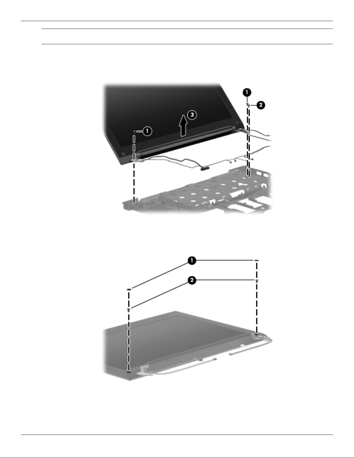
Removal and replacement procedures
CAUTION: Support the display assembly when removing the following screws. Failure to support the display
Ä
assembly can result in damage to the display assembly and other computer components.
2. Remove the two Torx T8M2.5×4.0 screws 1 and the Torx T8M2.5×9.0 screw 2 that secure the display
assembly to the base enclosure.
3. Lift the display assembly 3 straight up and remove it.
4. If it is necessary to replace the display bezel or any of the display assembly internal components:
a. Remove the two rubber screw covers 1 and the two Phillips PM2.5×5.0 screws 2 that secure the display
bezel to the display enclosure.
4–44 Maintenance and Service Guide
Page 80

Removal and replacement procedures
b. Flex the inside edges of the top edge 1, the left and right sides 2, and the bottom edge 3 of the display
bezel until the bezel disengages from the display enclosure.
c. Remove the display bezel 4. The display bezel is available using spare part number 618832-001.
5. If it is necessary to replace the webcam module:
a. Release the webcam module 1 as far from the display enclosure as the webcam module cable allows.
(The webcam module is attached to the display enclosure with double-sided tape.)
b. Disconnect the webcam module cable 2 from the webcam module.
c. Remove the webcam module. The webcam module is available using spare part number 618842-001.
Maintenance and Service Guide 4–45
Page 81

Removal and replacement procedures
6. If it is necessary to replace the display hinges:
a. Remove the eight Torx T8M2.5×4.0 screws 1 that secure the display hinges to the display enclosure.
b. Remove the display hinges 2. The display hinges are available in the Display Hinge Kit, spare part number
581094-001.
4–46 Maintenance and Service Guide
Page 82
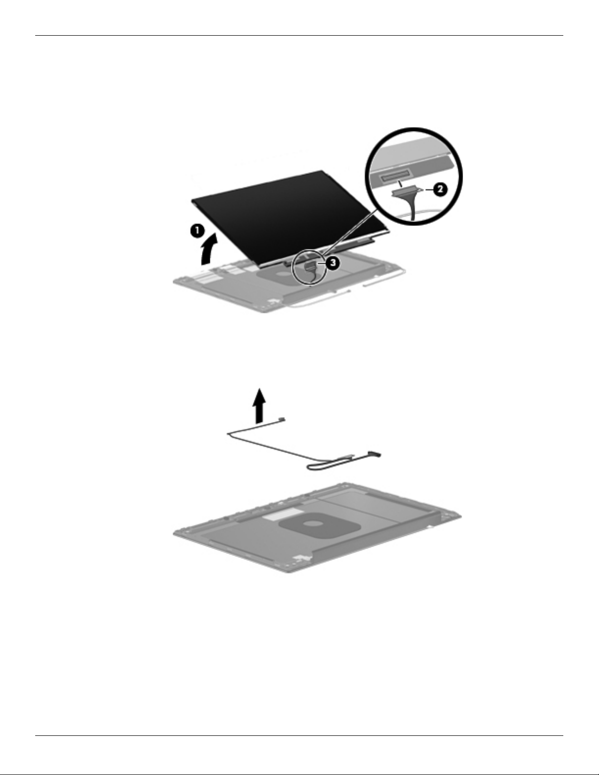
Removal and replacement procedures
7. If it is necessary to replace the display panel cable:
a. Lift the top edge of the display panel 1 until it detaches from the display enclosure.
b. Release the support bar 2 that secures the display panel cable connector to the display panel.
c. Disconnect the display panel cable 3 from the display panel.
d. Remove the display panel.
e. Remove the display panel cable. The display panel cable is included in the Display Cable Kit, spare
part number 618833-001.
Maintenance and Service Guide 4–47
Page 83
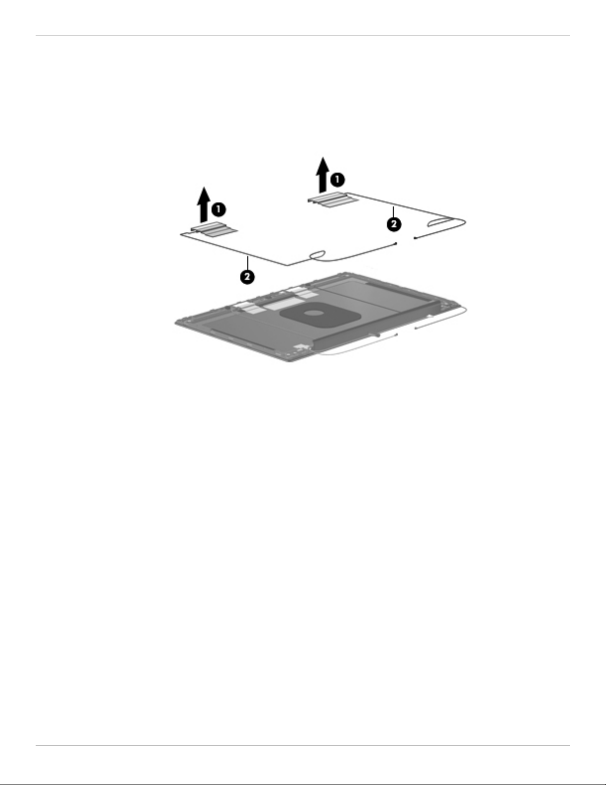
Removal and replacement procedures
8. If it is necessary to replace the WWAN antenna transceivers and cables:
a. Detach the WWAN antenna transceivers 1 from the display enclosure. (The transceivers are attached to the
enclosure with double-sided tape.)
b. Release the WWAN antenna cables 2 from the clips and routing channels built into the left and right sides
of the display enclosure.
c. Remove the WWAN wireless antenna transceivers and cables. The wireless antenna transceivers and cables
are included in the Display Cable Kit, spare part number 618833-001.
4–48 Maintenance and Service Guide
Page 84

Removal and replacement procedures
9. If it is necessary to replace the WLAN antenna transceivers and cables:
a. Detach the WLAN antenna transceivers 1 from the display enclosure. (The transceivers are attached to the
enclosure with double-sided tape.)
b. Release the WLAN antenna cables 2 from the clips and routing channel built into the left and right sides of
the display enclosure.
c. Remove the WLAN wireless antenna transceivers and cables. The wireless antenna transceivers and cables
are included in the Display Cable Kit, spare part number 618833-001.
10. If it is necessary to replace the microphones and cables:
a. Release the microphone receivers 1 from the clips built into the display enclosure.
b. Release the microphone cables 2 from the clips and routing channel built into the left side of the
display enclosure.
c. Remove the microphones and cables. The microphones and cables are included in the Display Cable Kit,
spare part number 618833-001.
Reverse this procedure to reassemble and install the display assembly.
Maintenance and Service Guide 4–49
Page 85

Removal and replacement procedures
4–50 Maintenance and Service Guide
Page 86

Computer Setup in Windows 7
Starting Computer Setup
Computer Setup is a preinstalled, ROM-based utility that can be used even when the operating system is not
working or will not load.
Some of the Computer Setup menu items listed in this guide may not be supported by your computer.
✎
An external keyboard or mouse connected to a USB port can be used with Computer Setup only if USB legacy
✎
support is enabled.
To start Computer Setup, follow these steps:
1. Turn on or restart the computer, and then press
displayed at the bottom of the screen.
2. Press
f10 to enter BIOS Setup.
5
Computer Setup
esc while the “Press the ESC key for Startup Menu” message is
Using Computer Setup
Navigating and selecting in Computer Setup
The information and settings in Computer Setup are accessed from the File, Security, Diagnostics, and System
Configuration menus.
To navigate and select in Computer Setup, follow these steps:
1. Turn on or restart the computer, and then press
displayed at the bottom of the screen.
❏ To select a menu or a menu item, use the tab key and the keyboard arrow keys and then press enter, or use a
pointing device to click the item.
❏ To scroll up and down, click the up arrow or the down arrow in the upper-right corner of the screen, or use
the up arrow key or the down arrow key.
❏ To close open dialog boxes and return to the main Computer Setup screen, press esc, and then follow the
on-screen instructions.
You can use either a pointing device (TouchPad, pointing stick, or USB mouse) or the keyboard to navigate and
✎
make selections in Computer Setup.
2. Press f10 to enter BIOS Setup.
3. Select the File, Security, Diagnostics, or System Configuration menu.
esc while the “Press the ESC key for Startup Menu” message is
Maintenance and Service Guide 5–1
Page 87

Computer Setup
To exit Computer Setup menus, choose one of the following methods:
■ To exit Computer Setup menus without saving your changes, click the Exit icon in the lower-left corner of the
screen, and then follow the on-screen instructions.
– or –
Use the
– or –
■ To save your changes and exit Computer Setup menus, click the Save icon in the lower-left corner of the
screen, and then follow the on-screen instructions.
– or –
Use the
Your changes go into effect when the computer restarts.
tab key and the arrow keys to select File > Ignore Changes and Exit, and then press enter.
tab key and the arrow keys to select File > Save Changes and Exit, and then press enter.
Restoring factory settings in Computer Setup
Restoring defaults will not change the hard drive mode.
✎
To return all settings in Computer Setup to the values that were set at the factory, follow these steps:
1. Turn on or restart the computer, and then press
displayed at the bottom of the screen.
2. Press
3. Use a pointing device or the arrow keys to select File > Restore Defaults.
4. Follow the on-screen instructions.
5. To save your changes and exit, click the Save icon in the lower-left corner of the screen, and then follow the
f10 to enter BIOS Setup.
on-screen instructions.
– or –
Use the arrow keys to select File > Save Changes and Exit, and then press
esc while the “Press the ESC key for Startup Menu” message is
enter.
Your changes go into effect when the computer restarts.
Your password settings and security settings are not changed when you restore the factory settings.
✎
5–2 Maintenance and Service Guide
Page 88

Computer Setup menus
The menu tables in this section provide an overview of Computer Setup options.
Some of the Computer Setup menu items listed in this chapter may not be supported by your computer.
✎
File menu
Select To do this
System Information ■ View identification information for the computer and
Restore Defaults Replace the configuration settings in Computer Setup with
Reset BIOS security to factory default Resets password to the factory default in case of a forgotten
Ignore Changes and Exit Cancel any changes entered during the current session.
Save Changes and Exit Save any changes entered during the current session.
Computer Setup
the batteries in the system.
■ View specification information for the processor, memory
size, system ROM, video revision, and keyboard controller
version, and wireless identification numbers.
the original factory settings. (Hard drive mode, password
settings, and security settings are not changed when you
restore the factory settings.)
password.
Then exit and restart the computer.
Then exit and restart the computer. Your changes go into
effect when the computer restarts.
Security menu
Some of the menu items listed in this section may not be supported by your computer.
✎
Select To do this
Setup BIOS Administrator Password Set up a BIOS administrator password.
User Management (requires a BIOS administrator password) ■ Create a new BIOS user account.
Password Policy (requires a BIOS administrator password) Revise password policy criteria.
HP SpareKey Enable/disable HP SpareKey (enabled by default).
Always Prompt for HP SpareKey Enrollment Enable/disable HP SpareKey enrollment (enabled by default).
Fingerprint Reset on Reboot (If Present) Reset/clear the fingerprint reader ownership (select models
Allow reset of HP ProtectTools security keys Enable/disable reset of HP ProtectTools security keys.
Change Password Enter, change, or delete a BIOS administrator password.
HP SpareKey Enrollment Enroll or reset HP SpareKey, which is a set of security
■ View a list of ProtectTools users.
only; disabled by default).
questions and answers used if you forget your password.
(Continued)
Maintenance and Service Guide 5–3
Page 89

Computer Setup
Select To do this
Security menu (continued)
DriveLock Passwords ■ Enable/disable DriveLock on any computer hard drive
TPM Embedded Security Enable/disable support for Trusted Platform Module (TPM)
Automatic DriveLock Enable/disable Automatic DriveLock support.
Disk Sanitizer Run Disk Sanitizer to destroy all existing data on the primary
(enabled by default).
■ Change a DriveLock user password or master password.
DriveLock settings are accessible only when you enter
✎
Computer Setup by turning on (not restarting)
the computer.
Embedded Security, which protects the computer from
unauthorized access to owner functions available in
Embedded Security for ProtectTools. For more information,
refer to the ProtectTools software Help.
You must have a setup password to change this
✎
setting.
hard drive or the drive in the upgrade bay.
If you run Disk Sanitizer, the data on the selected drive
✎
is destroyed permanently.
System IDs Enter a user-defined computer asset tracking number and
Diagnostics menu
Select To do this
System Diagnostics menu ■ F1 System Information—Displays the
ownership tag.
following information:
❐ Identification information for the computer and the
batteries in the system.
❐ Specification information for the processor, memory
size, system ROM, video revision, keyboard controller
version, and wireless identification numbers.
■ F2 Start-up Test—Verifies the system components needed
for starting the computer.
■ F3 Run-In Test—Runs a comprehensive check on
system memory.
■ F4 Hard Disk Test—Runs a comprehensive self-test on
any hard drive in the system.
■ F5 Error Log—Displays a log file if any errors
have occurred.
5–4 Maintenance and Service Guide
Page 90

System Configuration menu
Some of the listed System Configuration options may not be supported by your computer.
✎
Select To do this
Language Change the Computer Setup language.
Boot Options ■ Set a Startup Menu delay (in seconds).
Device Configurations ■ Enable/disable USB legacy support (enabled by default).
Computer Setup
■ Enable/disable Custom Logo (disabled by default).
■ Enable/disable Display Diagnostic URL (enabled
by default).
■ Enable/disable CD-ROM boot (enabled by default).
■ Enable/disable SD Card boot (enabled by default).
■ Enable/disable floppy boot (enabled by default).
■ Enable/disable PXE Internal NIC boot (enabled by default).
■ Set the Express Boot Popup delay in seconds.
■ Set the boot order.
When enabled, USB legacy support allows the following:
❐ Use of a USB keyboard in Computer Setup even when a
Windows operating system is not running.
❐ Startup from bootable USB devices, including a hard
drive, diskette drive, or optical drive connected by a USB
port to the computer.
■ Select a parallel port mode: ECP (Enhanced Capabilities
Port), standard, bidirectional, or EPP (Enhanced
Parallel Port).
■ Enable/disable fan always on while connected to an AC
outlet (enabled by default).
■ Enable/disable Data Execution Prevention. When enabled,
the processor can disable some virus code execution,
which helps to improve computer security.
■ Enable/disable LAN Power Save (select models only).
When enabled, saves power by turning off the LAN when
not in use (enabled by default).
■ SATA (Serial Advanced Technology Attachment) device
mode. The following options are available:
❐ AHCI (Advanced Host Controller Interface)
❐ IDE (Integrated Drive Electronics)
❐ RAID (select models only)
Availability of the options above varies by
✎
computer model.
■ Enable/disable secondary battery fast charge (enabled by
default).
■ Enable/disable HP QuickLook 3 (enabled by default).
■ Enable/disable Virtualization Technology (select models
only; disabled by default).
■ Enable/disable TXT (Intel Trusted Execution Technology)
(select models only; disabled by default).
(Continued)
Maintenance and Service Guide 5–5
Page 91

Computer Setup
Select To do this
System Configuration menu (continued)
Device Configurations (continued) ■ Enable/disable Dual Core CPU (select models only;
Built-In Device Options ■ Enable/disable the wireless button state (enabled
Port Options (all are enabled by default)
enabled by default).
■ Enable/Disable Unified Extensible Firmware Interface
(UEFI) mode (disabled by default).
■ Turn the Numlock state at boot on or off.
by default).
■ Enable/disable the embedded WLAN device (enabled
by default).
■ Enable/disable embedded WWAN device radio (select
models only; enabled by default).
■ Enable/disable embedded Bluetooth device radio (enabled
by default).
■ Enable/disable the Network Interface Controller (LAN)
(enabled by default).
■ Enable/disable LAN/WLAN switching (disabled by default).
■ Set the wake on LAN state. Options include the following:
❐ Disabled
❐ Boot to Network (set by default)
❐ Follow Boot Order
■ Enable/disable the fingerprint device (enabled by default).
■ Enable/disable a modem device (enabled by default).
■ Enable the ambient light sensor (enabled by default).
■ Enable/disable the Notebook MultiBay device (enabled
by default).
■ Enable/disable the integrated camera (select models only;
enabled by default).
■ Enable/disable optical disk drive (enabled by default).
■ Enable/disable internal microphones (enabled by default).
All port options are enabled by default.
✎
■ Enable/disable the Smart Card slot.
■ Enable/disable the ExpressCard slot.
■ Enable/disable the serial port.
■ Enable/disable the parallel port.
■ Enable/disable the flash media reader.
■ Enable/disable the USB port.
Disabling the USB port also disables MultiBay devices
Ä
and ExpressCard devices on the advanced
port replicator.
■ Enable/disable the 1394 port.
Set Security Level Change, view, or hide security levels for all BIOS menu items.
Restore Security Defaults Restore the default security settings.
5–6 Maintenance and Service Guide
Page 92

Computer Setup in Windows Vista
Starting Computer Setup
Computer Setup is a preinstalled, ROM-based utility that can be used even when the operating system is not
working or will not load.
Some of the Computer Setup menu items listed in this guide may not be supported by your computer.
✎
An external keyboard or mouse connected to a USB port can be used with Computer Setup only if USB legacy
✎
support is enabled.
To start Computer Setup, follow these steps:
1. Turn on or restart the computer, and then press
displayed at the bottom of the screen.
2. Press
Using Computer Setup
f10 to enter BIOS Setup.
Computer Setup
esc while the “Press the ESC key for Startup Menu” message is
Navigating and selecting in Computer Setup
The information and settings in Computer Setup are accessed from the File, Security, Diagnostics, and System
Configuration menus.
To navigate and select in Computer Setup, follow these steps:
1. Turn on or restart the computer, and then press
displayed at the bottom of the screen.
❏ To select a menu or a menu item, use the tab key and the keyboard arrow keys and then press enter, or use a
pointing device to click the item.
❏ To scroll up and down, click the up arrow or the down arrow in the upper-right corner of the screen, or use
the up arrow key or the down arrow key.
❏ To close open dialog boxes and return to the main Computer Setup screen, press esc, and then follow the
on-screen instructions.
You can use either a pointing device (TouchPad, pointing stick, or USB mouse) or the keyboard to navigate
✎
and make selections in Computer Setup.
2. Press f10 to enter BIOS Setup.
3. Select the File, Security, Diagnostics, or System Configuration menu.
To exit Computer Setup menus, choose one of the following methods:
■ To exit Computer Setup menus without saving your changes, click the Exit icon in the lower-left corner of the
screen, and then follow the on-screen instructions.
– or –
Use the
– or –
■ To save your changes and exit Computer Setup menus, click the Save icon in the lower-left corner of the
screen, and then follow the on-screen instructions.
– or –
Use the
tab key and the arrow keys to select File > Ignore Changes and Exit, and then press enter.
tab key and the arrow keys to select File > Save Changes and Exit, and then press enter.
esc while the “Press the ESC key for Startup Menu” message is
Your changes go into effect when the computer restarts.
Maintenance and Service Guide 5–7
Page 93

Computer Setup
Restoring factory settings in Computer Setup
Restoring defaults will not change the hard drive mode.
✎
To return all settings in Computer Setup to the values that were set at the factory, follow these steps:
1. Turn on or restart the computer, and then press
displayed at the bottom of the screen.
2. Press
3. Use a pointing device or the arrow keys to select File > Restore Defaults.
4. Follow the on-screen instructions.
5. To save your changes and exit, click the Save icon in the lower-left corner of the screen, and then follow the
Your changes go into effect when the computer restarts.
Your password settings and security settings are not changed when you restore the factory settings.
f10 to enter BIOS Setup.
on-screen instructions.
– or –
Use the arrow keys to select File > Save Changes and Exit, and then press
esc while the “Press the ESC key for Startup Menu” message is
✎
enter.
Computer Setup menus
The menu tables in this section provide an overview of Computer Setup options.
Some of the Computer Setup menu items listed in this chapter may not be supported by your computer.
✎
File menu
Select To do this
System Information ■ View identification information for the computer and the
Restore Defaults Replace the configuration settings in Computer Setup with
Reset BIOS security to factory default Resets password to the factory default in case of a forgotten
Ignore Changes and Exit Cancel any changes entered during the current session. Then
Save Changes and Exit Save any changes entered during the current session. Then
batteries in the system.
■ View specification information for the processor, memory
size, system ROM, video revision, keyboard controller
version, and wireless identification numbers.
the original factory settings. (Hard drive mode, password
settings, and security settings are not changed when you
restore the factory settings.)
password.
exit and restart the computer.
exit and restart the computer. Your changes go into effect
when the computer restarts.
5–8 Maintenance and Service Guide
Page 94

Security menu
Some of the menu items listed in this section may not be supported by your computer.
✎
Select To do this
Setup BIOS Administrator Password Set up a BIOS administrator password.
User Management (requires a BIOS administrator password) ■ Create a new BIOS user account.
Password Policy (requires a BIOS administrator password) Revise password policy criteria.
HP SpareKey Enable/disable HP SpareKey (enabled by default).
Always Prompt for HP SpareKey Enrollment Enable/disable HP SpareKey enrollment (enabled by default).
Fingerprint Reset on Reboot (If Present) Reset/clear the fingerprint reader ownership (select models
Allow reset of HP ProtectTools security keys Enable/disable reset of HP ProtectTools security keys.
Change Password Enter, change, or delete a BIOS administrator password.
HP SpareKey Enrollment Enroll or reset HP SpareKey, which is a set of security
DriveLock Passwords ■ Enable/disable DriveLock on any computer hard drive
TPM Embedded Security Enable/disable support for Trusted Platform Module (TPM)
Automatic DriveLock Enable/disable Automatic DriveLock support.
Disk Sanitizer Run Disk Sanitizer to destroy all existing data on the primary
Computer Setup
■ View a list of ProtectTools users.
only; disabled by default).
questions and answers used if you forget your password.
(enabled by default).
■ Change a DriveLock user password or master password.
DriveLock settings are accessible only when you enter
✎
Computer Setup by turning on (not restarting)
the computer.
Embedded Security, which protects the computer from
unauthorized access to owner functions available in
Embedded Security for ProtectTools. For more information,
refer to the ProtectTools software Help.
You must have a setup password to change
✎
this setting.
hard drive or the drive in the upgrade bay.
If you run Disk Sanitizer, the data on the selected drive
Ä
is destroyed permanently.
System IDs Enter a user-defined computer asset tracking number and
ownership tag.
Maintenance and Service Guide 5–9
Page 95

Computer Setup
Diagnostics menu
Select To do this
System Diagnostics menu ■ F1 System Information—Displays the
System Configuration menu
following information:
❐ Identification information for the computer and the
batteries in the system.
❐ Specification information for the processor, memory
size, system ROM, video revision, keyboard controller
version, and wireless identification numbers.
■ F2 Start-up Test—Verifies the system components needed
for starting the computer.
■ F3 Run-In Test—Runs a comprehensive check on
system memory.
■ F4 Hard Disk Test—Runs a comprehensive self-test on
any hard drive in the system.
■ F5 Error Log—Displays a log file if any errors
have occurred.
Some of the listed System Configuration options may not be supported by your computer.
✎
Select To do this
Language Change the Computer Setup language.
Boot Options ■ Set a Startup Menu delay (in seconds).
■ Enable/disable Custom Logo (disabled by default).
■ Enable/disable Display Diagnostic URL (enabled
by default).
■ Enable/disable CD-ROM boot (enabled by default).
■ Enable/disable SD Card boot (enabled by default).
■ Enable/disable floppy boot (enabled by default).
■ Enable/disable PXE Internal NIC boot (enabled by default).
■ Set the Express Boot Popup delay in seconds.
■ Set the boot order.
Device Configurations ■ Enable/disable USB legacy support (enabled by default).
When enabled, USB legacy support allows the following:
❐ Use of a USB keyboard in Computer Setup even when a
Windows operating system is not running.
❐ Startup from bootable USB devices, including a hard
drive, diskette drive, or optical drive connected by a USB
port to the computer.
■ Select a parallel port mode: ECP (Enhanced Capabilities
Port), standard, bidirectional, or EPP (Enhanced
Parallel Port).
■ Enable/disable fan always on while connected to an AC
outlet (enabled by default).
(Continued)
5–10 Maintenance and Service Guide
Page 96

Computer Setup
Select To do this
System Configuration menu (continued)
Device Configurations (continued) ■ Enable/disable Data Execution Prevention. When enabled,
the processor can disable some virus code execution,
which helps to improve computer security.
■ Enable/disable LAN Power Save (select models only).
When enabled, saves power by turning off the LAN when
not in use (enabled by default).
■ SATA (Serial Advanced Technology Attachment) device
mode. The following options are available:
❐ AHCI (Advanced Host Controller Interface)
❐ IDE (Integrated Drive Electronics)
❐ RAID (select models only)
Availability of the options above varies by
✎
computer model.
■ Enable/disable secondary battery fast charge (enabled
by default).
■ Enable/disable HP QuickLook 3 (enabled by default).
■ Enable/disable Virtualization Technology (select models
only; disabled by default).
■ Enable/disable TXT (Intel Trusted Execution Technology)
(select models only; disabled by default).
■ Enable/disable Dual Core CPU (select models only;
enabled by default).
■ Enable/Disable Unified Extensible Firmware Interface
(UEFI) mode (disabled by default).
■ Turn the Numlock state at boot on or off.
Built-In Device Options ■ Enable/disable the wireless button state (enabled
by default).
■ Enable/disable the embedded WLAN device (enabled
by default).
■ Enable/disable embedded WWAN device radio (select
models only; enabled by default).
■ Enable/disable embedded Bluetooth device radio (enabled
by default).
■ Enable/disable the Network Interface Controller (LAN)
(enabled by default).
■ Enable/disable LAN/WLAN switching (disabled by default).
■ Set the wake on LAN state. Options include the following:
❐ Disabled
❐ Boot to Network (set by default)
❐ Follow Boot Order
■ Enable/disable the fingerprint device (enabled by default).
(Continued)
Maintenance and Service Guide 5–11
Page 97

Computer Setup
Select To do this
System Configuration menu (continued)
Built-In Device Options (continued) ■ Enable/disable a modem device (enabled by default).
■ Enable the ambient light sensor (enabled by default).
■ Enable/disable the Notebook MultiBay device (enabled
by default).
■ Enable/disable the integrated camera (select models only;
enabled by default).
■ Enable/disable optical disk drive (enabled by default).
■ Enable/disable internal microphones (enabled by default).
Port Options (all are enabled by default)
Set Security Level Change, view, or hide security levels for all BIOS menu items.
Restore Security Defaults Restore the default security settings.
All port options are enabled by default.
✎
■ Enable/disable the Smart Card slot.
■ Enable/disable the ExpressCard slot.
■ Enable/disable the serial port.
■ Enable/disable the parallel port.
■ Enable/disable the flash media reader.
■ Enable/disable the USB port.
Disabling the USB port also disables MultiBay devices
Ä
and ExpressCard devices on the advanced
port replicator.
■ Enable/disable the 1394 port.
5–12 Maintenance and Service Guide
Page 98

Computer Setup in Windows XP
Starting Computer Setup
Computer Setup is a preinstalled, ROM-based utility that can be used even when the operating system is not
working or will not load.
Some of the Computer Setup menu items listed in this guide may not be supported by your computer.
✎
An external keyboard or mouse connected to a USB port can be used with Computer Setup only if USB legacy
✎
support is enabled.
To start Computer Setup, follow these steps:
1. Turn on or restart the computer, and then press
displayed at the bottom of the screen.
2. Press
Using Computer Setup
f10 to enter BIOS Setup.
Computer Setup
esc while the “Press the ESC key for Startup Menu” message is
Navigating and selecting in Computer Setup
The information and settings in Computer Setup are accessed from the File, Security, Diagnostics, and System
Configuration menus.
To navigate and select in Computer Setup, follow these steps:
1. Turn on or restart the computer, and then press
displayed at the bottom of the screen.
❏ To select a menu or a menu item, use the tab key and the keyboard arrow keys and then press enter, or use a
pointing device to click the item.
❏ To scroll up and down, click the up arrow or the down arrow in the upper-right corner of the screen, or use
the up arrow key or the down arrow key.
❏ To close open dialog boxes and return to the main Computer Setup screen, press esc, and then follow the
on-screen instructions.
You can use either a pointing device (TouchPad, pointing stick, or USB mouse) or the keyboard to
✎
navigate and make selections in Computer Setup.
2. Press
3. Select the File, Security, Diagnostics, or System Configuration menu.
To exit Computer Setup menus, choose one of the following methods:
■ To exit Computer Setup menus without saving your changes, click the Exit icon in the lower-left corner of the
■ To save your changes and exit Computer Setup menus, click the Save icon in the lower-left corner of the
f10 to enter BIOS Setup.
screen, and then follow the on-screen instructions.
– or –
Use the
– or –
screen, and then follow the on-screen instructions.
– or –
Use the
tab key and the arrow keys to select File > Ignore Changes and Exit, and then press enter.
tab key and the arrow keys to select File > Save Changes and Exit, and then press enter.
esc while the “Press the ESC key for Startup Menu” message is
Maintenance and Service Guide 5–13
Page 99

Computer Setup
Your changes go into effect when the computer restarts.
Restoring factory settings in Computer Setup
Restoring defaults will not change the hard drive mode.
✎
To return all settings in Computer Setup to the values that were set at the factory, follow these steps:
1. Turn on or restart the computer, and then press
displayed at the bottom of the screen.
2. Press
3. Use a pointing device or the arrow keys to select File > Restore Defaults.
4. Follow the on-screen instructions.
5. To save your changes and exit, click the Save icon in the lower-left corner of the screen, and then follow the
Your changes go into effect when the computer restarts.
Your password settings and security settings are not changed when you restore the factory settings.
f10 to enter BIOS Setup.
on-screen instructions.
– or –
Use the arrow keys to select File > Save Changes and Exit, and then press
esc while the “Press the ESC key for Startup Menu” message is
✎
enter.
Computer Setup menus
The menu tables in this section provide an overview of Computer Setup options.
Some of the Computer Setup menu items listed in this chapter may not be supported by your computer.
✎
File menu
Select To do this
System Information ■ View identification information for the computer and
Restore Defaults Replace the configuration settings in Computer Setup with
Reset BIOS security to factory default Resets password to the factory default in case of a
Ignore Changes and Exit Cancel any changes entered during the current session.
Save Changes and Exit Save any changes entered during the current session.
the batteries in the system.
■ View specification information for the processor, memory
size, system ROM, video revision, keyboard controller
version, and wireless identification version.
the original factory settings. (Hard drive mode, password
settings, and security settings are not changed when you
restore the factory settings.)
forgotten password.
Then exit and restart the computer.
Then exit and restart the computer. Your changes go into
effect when the computer restarts.
5–14 Maintenance and Service Guide
Page 100

Security menu
Some of the menu items listed in this section may not be supported by your computer.
✎
Select To do this
Setup BIOS Administrator Password Set up a BIOS administrator password.
User Management (requires a BIOS administrator password) ■ Create a new BIOS user account.
Password Policy (requires a BIOS administrator password) Revise password policy criteria.
HP SpareKey Enable/disable HP SpareKey (enabled by default).
Always Prompt for HP SpareKey Enrollment Enable/disable HP SpareKey enrollment (enabled by default).
Fingerprint Reset on Reboot (If Present) Reset/clear the fingerprint reader ownership (select models
Allow reset of HP ProtectTools security keys Enable/disable reset of HP ProtectTools security keys.
Change Password Enter, change, or delete a BIOS administrator password.
HP SpareKey Enrollment Enroll or reset HP SpareKey, which is a set of security
DriveLock Passwords ■ Enable/disable DriveLock on any computer hard drive
TPM Embedded Security Enable/disable support for Trusted Platform Module (TPM)
Automatic DriveLock Enable/disable Automatic DriveLock support.
Disk Sanitizer Run Disk Sanitizer to destroy all existing data on the primary
Computer Setup
■ View a list of ProtectTools users.
only; disabled by default).
questions and answers used if you forget your password.
(enabled by default).
■ Change a DriveLock user password or master password.
DriveLock settings are accessible only when you enter
✎
Computer Setup by turning on (not restarting)
the computer.
Embedded Security, which protects the computer from
unauthorized access to owner functions available in
Embedded Security for ProtectTools. For more information,
refer to the ProtectTools software Help.
You must have a setup password to change
✎
this setting.
hard drive or the drive in the upgrade bay.
If you run Disk Sanitizer, the data on the selected drive
Ä
is destroyed permanently.
System IDs Enter a user-defined computer asset tracking number and
ownership tag.
Maintenance and Service Guide 5–15
 Loading...