

Page 1

SA
ICR®
ETER
.
.®
Page 2
Page 3
CERTIFICATION
THE
THAT
TESTED
MEET
IT
I)FURTHER
MEASUREMENTS
NATIONAL
EXTENT
BRATION
HEWLETT-PACKARD
THIS
ITS
WAS
ALLOWED
INSTRUMENT
AND
PUBLISHED
SHIPPED
CERTIFIES
BUREAU
FACILITY
INSPECTED
FROM
ARE
OF
BY
.
COMPANY
WAS
SPECIFICATIONS
THE
THAT
TRACEABLE
STANDARDS
THE
THOROUGHLY
AND
FACTORY
ITS
CALIBRATION
BUREAU'S
CERTIFIES
FOUND
WHEN
.
TO
TO
THE
THE
CALI-
TO
Page 4
OPERATING
MODEL
SERIALS
AND
SERVICE
PREFIXED
425A
:
142
MANUAL
-
DCMICROVOLT-AMMETER
001304
Copyright
1501
PAGE
HEWLETT-PACKARD
MML
ROAD,
PALO
ALTO,
-i"
COMPANY
CALIFORNIA,U.S.A.
1958
Printed:DEC
1963
Page 5

To
adapt
changes
Instrument
142-
ERRATA
this
manualtoinstruments
shownintables
Serial
Prefix
:
.
#
MANUAL
DC
MICROVOLT-AMMETER
Manual
Manual
with
other
Make
Manual
ERRATA
Figure
Table
Table
5-12,
R12:Change
R13:Change
6-1,
CR1,
CR2:Change
J2:Changetofollowing
5060-0625
5060-0633
0340-0087
0340-0091
J3:Changetofollowing
5060-0632
5060-0633
0340-0087
0340-0091
M1:Change
R68:Change
V7,
V8
:
replaceable
XV7,
XV8:Delete
replaceable
Under
MISCELLANEOUS,
Change
Change
Change
6-2,
Change~StockNo.
Change~WStockNo.
ChangeStockNo.
ChangeStockNo.
ChangeStockNo.
G30A,
Change
Change
ChangeStock
ChangeStockNo.
ChangeStockNo.
G-83P:Delete
0727-0077:Change
9110-0038:Change
9110-0039:Change
G30B:Delete
Cep
Changes
Schematic
value
value
IndexbyReference
Binding
Binding
Insulator,
Insulator,
Binding
Binding
Insulator,
Insulator,
G-81Eto(~W
resistor
Delete
stock
."
stock
."
G74to(~W
G74D
toStock
G74N
toStock
Replaceable
StockNo.
StockNo.
No
entire
CHANGES
MODEL
Serial
serial
to 0.953
to 0.28
G-29A-74
tolerance
number
StockNo.
AC-10C
AC-10D
AC-54B
AC-54F
G-29A-74to1902-0108
entire
G-74to0370-0025
G-74Dto0370-0026
.
G-74Nto0370-0035
G-76Jto5060-0625
G-81Eto1120-0306
listing
resistor
descriptionto"60
description
425A
Prefixed:142-
Printed:12/63
prefixes
Instrument
Diagram,
ohms
ohms
Designator,
to
description,
description,
StockNo.
number
Parts
Cep
post
and ground
post:red
triple:black,
triple:black,
post:black
post
:
red
triple:black,
triple:black,
from
and
and
0370-0025
No.0370-0026
No.0370-0035
.
to
5060-0632
to
5060-0633
to
0340-0087
to
0340-0091
listing
.
tolerance
to
"50
check
StockNo.
(rmo)
(rmo)
1120-0306
10%to1%
change
change
.
from
cycle
cycle."
for
errata below,
Serial
Prefix
1902-0108
link:black
internal
external
internal
external
descriptionto"Part
descriptionto"Part
.
.
.
.
.
.
.
.
.
.
.
.
.
10%
.
"
(rmo)
(rmo)
to1%.
and
make
Make
Manual
.
ofA5;
ofA5;
Changes
not
separately
not
separately
5/5/64
L
SupplementAfor
425A-902
Page 6

.
...
Model
425A
ListsofIllustrations
Table
of
Contents
and
Tables
Section
I
GENERAL
1-1.Description
1-3.Applications
1-5
.
II
PREPARATION
2-1.Introduction.. . . . . .
2-3
.
2-6.Power
2-10.Power
2-13.Installation
2-15.Repackaging
II
OPERATING
3-1.Introduction
3-3.Preliminary
3-4
.
3-7
.
3-9
.
3-12
.
3-14.Isolating
3-16
.
V CIRCUIT
4-1.General
V
MAINTENANCE
5-1
.
5-3.Test
5-6.Mechanical
INFORMATION
... . . . . .
... . . . .
Differences
Unpacking
Low-Level
Ground
AC
Operating
Operation
DESCRIPTION
Introduction.. . . . . . . . .
Equipment
between
FOR
USE
and
Inspection
Requirements
Cable
. . .
for
INSTRUCTIONS
Considerations
Electrical
Currents
Voltages
Procedure
the
Chassis
withaRecorder
.
. . . . .
.
. . . ... ... .
AdjustmentofMeter
. .
. ...
Instruments
. . .
. . . .
.
. ... . . .
Shipment
. . . . . .
Phenomena
.
. . . . . .
. ...
. ... . . .
.
.
. . . . . . .
. . . . . . .
.
. . . . . . .
TABLE
. . .
.
. .
. .
. . .
. . .
Zero
.
.
.
.
.
.
.
Page
1-1
1-1
2-1
2-1
2-1
2-1
2-1
2-1
2-1
3-1
3-1
3-1
3-1
3-1
3-1
3-1
3-2
4-1
4-1
5-1
5-1
5-1
5-1
. . ..1-1
. ...
.
. . . .
. .
. ...
. .
.
. . . .
. . . . .
.
. . . .
. . . ..3-1
... . .
OF
CONTENTS
Section
V
VI
MAINTENANCE
5-8
.
Troubleshooting
5-9
.
Introduction
5-11
.
Amplifier-Power
5-13
.
Chopper
5-15
.
Modulator
5-18
.
Demodulator
5-20.Repair
5-21
.
5-23
5-24
5-26
5-28
5-30
5-33
5-35
5-37
5-38
5-40
5-42
5-44
5-46
5-47
5-49
5-53
REPLACEABLE
6-1
6-4.Ordering
Introduction
.
Cabinet
.
Modulator
.
DemodulatorReplacement
.
Range
.
Disconnecting
Resistor
.
Replacement
Resistor
.
Servicing
..Adjustments
.
Introduction
.
Adjustment
Bias
.
Adjustment
.
Meter
.
Performance
.
Introduction
.
Voltmeter
.
Ammeter
.
Introduction
(Cont~d)
. . . . . . . .
. . . .
Assembly
Assembly
and
. .
Calibration
Assembly
Replacement
. . .
Removal
Replacement
Switch
Information.. . . .
Replacement.. . .
Input-Shunting
of
Input-Shunting
.
Etched
.
. . . . . .
.
of
Cathode
. . .
of
Twin-T
Check
. .
Check
Check
PARTS
. . .
. . . . .
Supply
. . . ...
. . . . . .
.
. .
. . .
.
. . ...
. . . .
. .
Circuit
. . . .
.
. . . .
.
. . .
. . . . . ...
. . . . . .
. . . .
Follower
. .
. . . .
Filters..
. .
. . . .
. . .
. .
. . .
. . .
. .
. . . .
. . . .
. ...
. . . .
Boards
. .
. .
. .
. .
. . .
. .
.
.
. .
. .
. .
. .
. .
. .
.
.
.
.
.
.
.
.
Page
.
.
5-1
5-1
5-1
5-1
5-2
5-3
5-3
5-3
5-3
5-3
5-4
5-4
5-6
5-6
5-6
5-6
5-6
5-6
5-7
5-8
5-8
5-8
5-8
5-10
6-1
6-1
6-1
Number
1-1
.Model
3-1
.
4-1
.Block
.
5-1
5-2
.
5-3
.Modulator
5-4
.Right
5-5
.Range
5-6
.Connection
5-7
.Left
Number
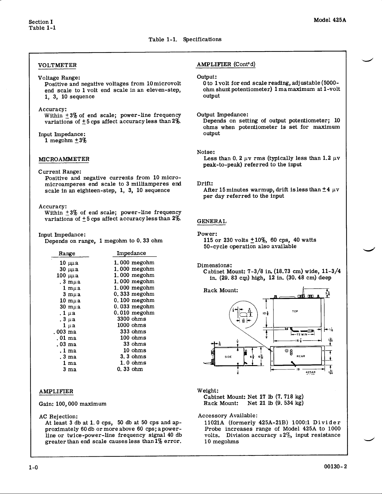
1-1.Specifications
5-1
.Equipment
5-2
.
Troubleshooting
5-3
.Voltmeter
00130-
4
425A
Operating
Diagram
A6,
Chopper
Modulator
Side
Switch
Resistor
Side
.3
MILLIVOLTS
Controls
Assembly
Waveform
View
Point
........,..
View
Required. . . . . .
Calibration(1VOLTS
LIST
Title
DC
Microvolt-Ammeter
... .. . . . ..
of
Model
425A
. ....
Assembly
Model
Detail........
of
Model
Title
. . . . . .
... . . . . .
. . . . . . .
.
. ... ... .
. . . .
425A
Input-Shunting
425A. .
ranges). . . . .
. . . . .
. . . .
. . . .
. . . .
through
OFILLUSTRATIONS
Page
. .
1-1
3-0
4-1
.
5-1
5-3
5-3
. .
5-4
5-5
5-6
5-7
LIST
OF
Page
. .
1-0
. . .
5-0
. .
.
5-2
.
5-9
Number
5-8
.Voltmeter
5-9
5-10.Ammeter
5-11.Voltage
5-12.Model
5-13.Function
5-14.Exploded
TABLES
Number
5-4
5-5
6-1
6-2
through
.Voltmeter
(100
VOLTS
and
.
Voltmeter
through
.Ammeter
.IndexbyReference
.Replaceable
Calibration
.3
Calibration
MICROVOLTS
ranges)
Calibration
and
425A
and
Viewof425A
11021A
Calibration
10
Calibration
Title
Test
Setup(1VOLTS
MILLIVOLT
...........5-8
Resistance
(Schematic
Range
(1000
:1
Title
MICROVOLTS
Designator
Parts
ranges)
Test
Setup
through10MICRO-
Test
Setup
Diagram
Diagram).. . .
Switch
. . .
Detail.. . .
(Standard)
Divider)
(100
.. . . . ....
Probes
MICROVOLTS
ranges)
. .
. . . . . . .
. ...
. . . .
. . .
. .
...5-9
. ..6-2
Page
.
Page
5-8
5-10
5-12
5-13
5-14
5-14
5-10
6-8
Page 7
Section
Table
I
1-1
1-1.Specifications
Table
Model
425A
VOLTMETER
Voltage
Accuracy
Input
MICROAMMETER
Current
Accuracy
Input
Range
Positive
end
scale
10
1,
3,
:
Within
variations
1
Positive
microamperes
scaleinan
Within
variationsof±
Depends
_+3%
Impedance
megohm
Range
:
±3%
Impedance
Range
10pl.a
30
100l.A
.3mt
1
3mpa
10m1a
30mga
.1l
.3l,
1g.
003
.01ma
.03
.1ma
.3ma
1
3
:
and
negative
to1volt
sequence
end
of
of
+5cps
:
±3%
:
and
negative
end
eighteen-step,
of
end
5 cps
:
on
range, 1
tiga
a
.a
mAa
a
a
a
ma
ma
ma
ma
voltages
end
scale;power-line
affect
currents
scaleto3
scale;power-line
affect
megohm
from
scaleinan
accuracy
from
milliamperes
1, 3,10sequence
accuracy
to0.33ohm
Imp
edanc
e
1
.000
megohm
1
.000
megohm
1.000
megohm
.000
megohm
1
megohm
1
.000
0.333
megohm
0.100
megohm
0
.033
megohm
megohm
0.010
3300
ohms
ohms
1000
333
ohms
100
ohms
33
ohms
10
ohms
3.3
ohms
1.0
ohms
0.33
ohm
10
microvolt
eleven-step,
frequency
less
than2%.
10
micro-
end
frequency
less than2%.
AMPLIFIER
Output
:
0to1
volt
ohm
shunt
output
Output
Noise
Drift
GENERAL
Power
Dimensions
Impedance
Depends
ohms
when
output
:
Less
than 0
peak-to-peak)
:
After15minutes
perday
115or230
50-cycle
Cabinet
referredtothe input
:
Mount:7-3/8in.
in.(29.83
(Cont'd)
for
end
potentiometer)1ma
:
on
settingofoutput
potentiometer
.2liv
referred
volts
operation
:
cqi)
scale
rms
warmup,
+10%,
also
high,
reading,
(typically
to
driftisless
60
available
(18.73
12 in.(30
adjustable (5000-
maximum
potentiometer;10
is
set for
the
input
cps,40watts
cm)
less
than1.2
than±4l
wide,
.48cm)
maximum
at
11-3/4
deep
1-volt
pv
.v
AMPLIFIER
Gain:100,
Rejection
AC
At
least
proximately
line
or
greater
000
maximum
:
3
dbat1.0
60dbor
twice-power-line
than
end
cps,50 db
more
scale
at 50
above60cps;a
frequency
causes
less
cps
and
ap-
power-
signal40db
than1%error
.
Weight
:
Cabinet
Rack
Accessory
11021A
Probe
volts.Division
10
Mount:Net17lb (7.718
Mount
Available
(formerly
increases
megohms
:Net21lb (9
:
425A-21B)
range
of
accuracyt2%,
kg)
.
534
kg)
1000:1Divider
Model425A
input
to
1000
resistance
00130-
2
Page 8

Model425A
1-1.DESCRIPTION
1-2.The
extremely
voltages
1
picoampere
of1megohm
due
measurements
tial,
from
whichwill
recorders.It
1-3.APPLICATIONS
1-4.The
example,inengineering:itisan
tor ordoamplifier,
Model
sensitive
from1microvoltto1
to
on
circuit
to
for
the
chassis
the
cabinet.The
drive
will
Model
.
425A
DC
measuring
3
milliamperes.An
all
voltage
loading
in
circuits
either
deliverupto
425A
The
.
which
and
input
Model
potentiometer
.
has
anditwill
Microvolt-Ammeter
ranges
circuit
425A
many
GENERAL
device
which
volt
and
currents
input
minimizes
Model
1milliampere
425A
are
off
ground
may
be
provides
or
galvanometer
applications.For
excellent
measurevacuum
SECTION
is
measures
from
resistance
errors
can
make
poten-
isolated
an output
atIvolt
null
detec-
tube
INFORMATION
an
ber
.
The
page
this
included
apply
serial
1
grid
currents
capacitors;in
nerve
potentials
and
chemistry:the
chamber
and
galvanic
1-5.DIFFERENCES
1-6
.
TheModel
with a
changes
prefix,
of
manual
changes
directly
number
and
medicine
measurements
actions
three
only
whenachangeismadeinthe
then,isan
this
manual
applies
with
this
to
be
made
to
prefix
leakage
and
plant
Model
.
BETWEEN
425A
carriesafive
digit
prefix
to
directly
manual
in
Models
.
Section
Paragraphs
currentsininsulators
and
biology:it
cell
potentials;andinphysics
425Aisusefulinionization
andcan
identifier,
indicate
the
425A
monitor
INSTRUMENTS
(000-00000).The
andison the
to
A
.
supplement
to
indicate
manual
to
which
1-1to1-6
will
thermocouple
digit
serial
instrument
which
instrument
the
necessary
make
the
carryadifferent
measure
num-
prefix
title
may
manual
I
and
.
.
be
00130-
Figure 1-1
3
.Model
425A
DC
Microvolt-Ammeter
Page 9

Page 10

Model
425A
Z-1.INTRODUCTION
2-2
This
.
inspection,
425A
2-3.UNPACKING
2-4
.Unpack
for
it
surfaces,
damage,
warranty
2-5.An
as
soonaspossible
inspection,alistofperformance
V,
paragraph
testaspartofincoming
section contains
repacking
.
the
instrument
signsofphysical
broken
fileaclaim
page
electrical
knobs,
the
at
5-46.These
.
and
AND
damage
etc
with
the
rearofthis
inspection
after
receipt.To
quality-control
SECTION
PREPARATION
informationonunpacking,
installationofthe
INSPECTION
upon
receipt
suchasscratched
.Ifthereisany
carrier
procedures
and
manual
should
checksareinsection
be
aidinelectrical
Model
.
and
inspect
panel
apparent
refertothe
.
performed
makeagood
inspection
II
Paragraphs
Section
2-1to2-16
11
FOR
Z-10.POWER
2-11
withathree-conductor
ged
into
ment
connectoristhe
2-12.To
erating
three-prongtotwo-prong
on the
2-13.INSTALLATION
2-14
quiringnopermanent
is
.
for
mountmounts
USE
.This
anappropriate
.The
.The
offset
preserve
instrument
adapter
Model
bench
CABLE
Hewlett-Packard
ground
to
ground
top
inastandard
.
power
receptacle,
pinonthe
pin
the
protection
fromatwo-contact
adapter
.
.
425A
isaportable
installation
operation
instrumentisequipped
cable
which,
when
power
.
.The
19-inch
grounds
cable
and
.The
Model
three-prong
feature
outlet,
connect
instrument
Model
425AR
rack
.
the instru
plug-
when
op-
use
topigtail
re-
425A
rack
a
Z-6
.
POWER
2-7
.The
a
115-volt60cps
converted
changing
power
series
place
ampere,
figure
2-8
.The
which
line
quency
the
which
Most
well
power
power
instrument,
cause
2-9
.The
factory
source
source,
two
filters
designed
the
Model
for
use
the dual 115-volt
transformer
configuration
the1ampere,slow-blow
slow-blow
5-13, for
Model
is
tunedtoa
frequency.A
of
instrument
does
commercial
within
plants
line
sluggish
.To
twin-T
are
factory
signal
the
mustbeoperated
not
vary
these
may
frequency
butiflarge
meter
Model
equipped
convertitto
you
must
filters
containedina
to
operate
under
REQUIREMENTS
425Aisnormally
power
details
425A
synchronous
power
425A
to
stock
supply, butitcan
froma230-volt,60cps source
from
a parallel configurationtoa
.At
the
fuse.See
.
uses an
frequency 5/6
appliedtothe
in
frequency
systems
limits
not
change
from
however,
;
Variations
.
do not
variations
response
is
normally
operate
operate
the
50
single
at41.7cps are
number
.
wired
primary
timeofthe
line
the
schematic
ac-coupled
designated
motor
fromapower
more
maintain
completely
and
lossofaccuracy
from
a
from
rejection
cps
to41.7 cps
plug-in
9110-0039
for
windings
change,
fuse
witha0
determines
amplifier
than_+5
small
from
designated
disable the
exist
shipped
60-cps
50-cps
a
frequency
unit
available
.
use
with
easily
of
the
re-
diagram,
amplifier
power
fre
.Thus
source
cps
frequency
portable
they
will
from
the
power
power
.Both
.Units
from
be
by
.5
of
Z-15.REPACKAGING
2-16.The
packaging
questions,
sales
a
.Ifpossible,
for the
b.Wrap
before
c.Use
of
the
strips
.
.
d.Use
house
bandstoseal the
e.Mark
Instrument",
If
Packard
tachtothe
owner
be
sure
number,
following
an
instrument
contact
representative
instrument
the
placingitin
plentyofpacking
instrument
.
heavy
the
instrument
the
the
instrument
and
accomplished.In
to
your
.
use
.
instrument
the
and
cardboard
container
packing
etc
.
Company
instrument
indicatingthe
identify
serial
listisa
for
authorized
the
shipping container
protect
and
box
Note
is tobeshippedtoHewlett-
for
the
prefix,
SHIPMENT
FOR
general
shipment.If
Hewlett-Packard
original
in
material
use
.
with
serviceorrepair,
any
instrument
container
heavy
paper
around
the
panel
carton
a
or
heavy
"Fragile", "Delicate
identifying
tag
serviceorrepair
correspondence
and
serial
guide for
you
or plastic
.
with
cardboard
wooden
tape
by
model
number
.
have
any
designed
all
sides
box
or
metal
atthe
to
be
.
re-
to
00130-
4
Page 11

.
Model
Section
Figure3-1
III
425A
1.Power
2.Pilot
3
.
4.RANGE
3-0
switch
Light.Lights
FUNCTION
;
atinVOLTAGE
o
switch.For
rent
range
Turns
.
switch.For
or
desired,
instrumenton.
when
instrumentison
selecting
CURREN
selecting voltage or
mode
Figure 3-1
of
.
oper-
cur-
5
6
7.OUTPUT
.Operating
ZERO
.
setting
Probe.Connected
.
voltageorcurrenttobe
shown)
drive
recorders
Controls
control
of
.Provides
either
.Used
meter
.
connector
potentiometer
.
to
an
to
INPUT
measured
(rear
output
adjust
of
electrical
connector,
here
instrument,
voltage
or
galvanometer
.
which
zero
apply
not
will
00130-2
Page 12
Model
425A
Paragraphs
Section
3-1to3-15
III
3-1.INTRODUCTION
3-2.This
and
information
on
the
3-3.PRELIMINARY
.LOW-LEVEL
3-4
3-5
.Stray
ent,inone
circuits.The
tween
age.Thus,
possibilityoflow-level
mocouples
cables
on
capacitors
two
terminals
vanic
of
the
3-6
.Errors
appreciable.The
to
haveavery
the
most
materials
(with their
istics
(84v/OC),
and
brass(24v/OC).As
wirewound
(known
and
"Ideal").If
sucharesistor
ference
volts
3-7
.GROUND
3-8
.Ground
zero
rents
differs
net
test
.They
leadofthe
is
addedtothe
and
eliminate
shorting strap
groundterminalsofOUTPUT
the
instrument
This
3-9
.AC
3-10
.The
Model
sients
the
instrument
ferent
00130-3
section gives
on the
Model
stray
action)
Model
versus
willbedeveloped
on
occur
procedure
425Aprovides
425A
low-level
form
or
Model
and
signal
when
using
(thermoelectric
(triboelectric
(dielectric
mounted
all
can
425A
.
duetothermal
probeofthe
low
thermoelectric
common
maybe
approximate
manganin
resistors
under
between
lower
from
power
VOLTAGES
when
than
electrical
encountered.Some
copper)
the
trade
the
and
the
CURRENTS
currents
rangesofthe
when
the
ground
flow
through
cable,
input
the
ground
between
(frontpanel on
isolates
low-pass
measuring
.By
the
line
Microvolt-Ammeter
function
CONSIDERATIONS
ELECTRICAL
electrical
another,
425A
voltages;it
the
electrical
effect),
onanimperfect
produce
are
(3
I4v/
are
namesof"Eureka",
Model
thereisa1.OOCtemperature
endsofthe
.
may
potentialofthe
producingavoltage
signal.To
.
filterinthe
adequate
do
usingamodulator
frequency,
OPERATING
.
preliminary
anduseofall
in
does
lower
effect),
apparent
absorption),
voltages within
voltages alone
Model
conductor
temperature-emf
constantan
aluminum
0
C),
an
example,
wound
425A
.
causeanoffset of
Model
potentialofthe
the
probe
break
currents,
chassis-groundand
connector
rack
chassis
rejectionofac
signals
considerations
.
PHENOMENA
phenomena
nearly
ranges,
with
is
from
stray
all
not
distinguish
measures
consider
phenomena.Ther-
flexing
residual
battery
insulator
425Ais
effect
with
.In
likelymaterials
(40
4v/
some
constantan
connected
resistor,40micro-
425A.These
Model
circuit
cable
the
ground
remove
on the
mount
instruments)
cabinet
input
circuitof
within
the
frequency
line-frequency
SECTION
controls
.
.
are
pres-
electrical
be-
net
volt-
of
coaxial
charges
action
(gal-
the
range
can
designed
copper,
use
other
character-
C),
O
steel
(3
4v/0Q,
high-grade
wire
"Advance",
across
dif-
meter
cur-
425A
cabi-
under
and
ground
drop
which
loop
the
metal
cabinet-
rear
.
the
and
tran-
range
dif-
INSTRUCTIONS
the
of
be
of
.
of
III
pickupisprevented
theacamplifier
3-11.AC
net
example,
chassis
the
mum
exceed
3-12.OPERATING
3-13.The
operating
a
b.Turn
minuteisrequired.For
ranges,
c.Set
d.Set
e.Clip
metertozero
maximum
ishing
f.Connect
ranges,
and
librium before
3-14
3-15.To
the
metal
voltages
without
full-scaledovalueofthe
.
Do
utes
most
Static
within
circuit
Do
on
ingresistors
overload
If
disconnectedinyour
of
To
externally
reconnect
graphs5-30to5-33)
.
affecting
line
and
cabinet
voltages
500
volts
following
the
Model
Attach
probetoinput
instrumenton.
allow
FUNCTION
RANGE
probe
range
effectonhigher
not
handle
priortomaking
sensitive
charges
the
probe
allow
sufficient
connection
not
overload
higher
.
the
one-megohm
the nine
use
these
ISOLATING
isolate
shorting
from
is
actually
can
frequency
between
peak
425A
approximately
switch
and
common
with
ZERO
of
about±50 l.v;
the
voltage
and
probe
to
considering
current
are
lowest
ranges,
withaone-megohm
input-shunting
chassisofthe
strap
producing
overdriven
exist
between
accuracyofthe
potential
canbe80to100dbgreater
chassis
.
PROCEDURE
isastep-by-step
.Proceed
connector
Warmup
maximum
15
switch
probe
must
the
THE
to
to
desired
clip
control
ranges
.
Note
for three or four
zero
and
temperature
have timetodissipate
circuit
time
for
points
reading
Note
instrument
ranges,
not
input-shunting
current
for
protected
instrument,
either
resistor
.
CHASSIS
between
any
error
.
chassis
instrument.For
difference
range
selected.Maxi-
and
cabinet
.
as
.
timeofabout
stabilityonlower
minutes
desired
range
together
ZERO
.
thusithas
adjustment
current
.On
to
rangesisaltered
more
probe,
reach
final
excessively
current-shunt-
from
resistor
calibration
shunt
instrument
resistor or
.
Model
chassis-ground
procedure
follows
warmup
function
.
and
control
on
ranges
gradients
common
thermal
.
extreme
(see
para-
425A,
and
must
min-
sensitive
two
remove
unless
cabi-
between
than
not
for
:
one
.
.
adjust
has
dimin-
.
.
clip,
equi-
is
.
and
Page 13

Section
Paragraph
cabinet-ground
catedonrearofinstrument
tween
peak
both
is itself
(precaution
3-16
chassis,
425A
III
3-16
chassis
.Isolate
a.Measurement
above
b.Measurement
Measurement
c
.
OPERATION
.
a.If
b.Connect
.
and
chassis
ground
isolated
against
conditions
also
isolate
recordertoOUTPUT
terminals
cabinet
under
is
between
potential
is
with
.
is
made
ground
WITH
require
recorder
of
OUTPUT
Potential
.
must
not
following
two
.
respecttoa
onamore
currents)
A
isolationofModel
chassis
connector
difference
exceed 500
conditions
points
ground
sensitive
.
RECORDER
.
connectorofModel
which
volts
:
which
range
.
425A
lo-
be-
are
Clip
probe
c
.
1
VOLT
adjust
on
control
trol.The
urements.Remember
proportional
gardlessofrange
range
d
f
recorder
.Set
e.Select
ZERO
meter
Calibrate
.
to
g.Set
meterofModel
(30
and
.
MICROVOLT
30
controltoproduce
microvolts)
systembyadjusting
produce
system
to
meter
common
zerotodesired
desired
is
now
selected
clip
rangeonModel
.
deflectiononrecorder
425A
to
ready
that
deflection
deflectionofModel
.
Model
together
positiononits
end-scale
output
AMP
zerowith
recordyour
to
of
recorder
425A
and
select
scale
425A,
deflection
LITUD
ZERO
con-
meas-
425A
.
and
E
.
is
re-
3-2
00130-2
Page 14
Model
425A
Paragraphs
Section
IV
4-1to4-3
4-1.GENERAL
.
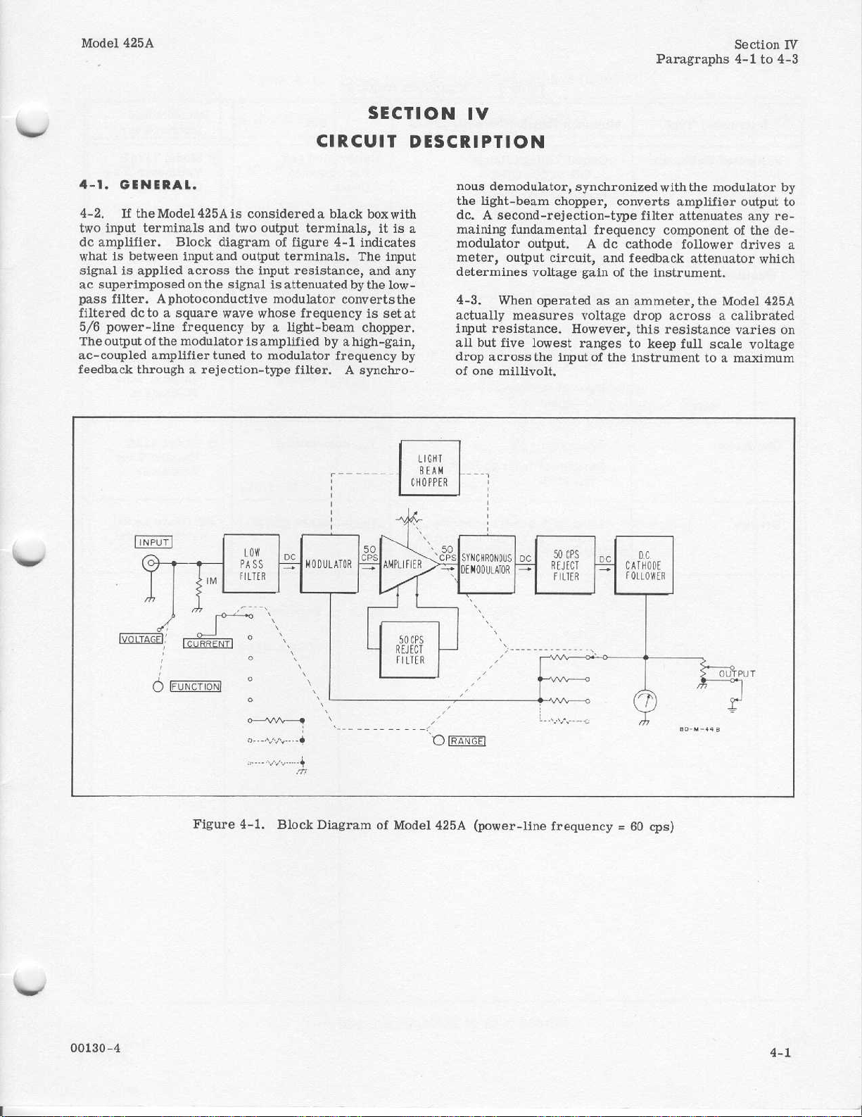
4-2
If
theMode1425Ais
two
input
terminalsand two
de
amplifier
.Block
whatisbetween
signalisapplied
ac
superimposed
filter.Aphotoconductive
pass
filtered
5/6
The
ac-coupled
feedback
dctoasquare
power-line
outputofthe
amplifier
through
.
considereda
diagramoffigure
input
and
output
across
onthe
frequency
modulator
the
input
signalisattenuatedbythe
whose
wave
by
is
tunedtomodulator
a rejection-type
SECTION
CIRCUIT
black
boxwith
output
amplifiedbyahigh-gain,
terminals,itis
4-1
terminals.The
resistance,
modulator
converts
frequencyissetat
a
light-beam
frequency
filter
.A
indicates
input
and
any
low-
the
chopper
by
synchro-
Iv
DESCRIPTION
nous
demodulator,synchronized
the
light-beam
dc.A
a
.
second-rejection-type
maining
modulator
meter,
determines
4-3
.When
actually
input
resistance
all
but
drop
across
of
one
chopper, converts
fundamentalfrequency
output.A
output
voltage
operated
measures
five
lowest
the
millivolt
circuit,
.
inputofthe
.
de
and
gain
as
voltage
However,
ranges
o£
an
with
the
amplifier
filter
attenuates
component
cathode
feedback
the
ammeter,
drop
this
to
follower
attenuator
instrument
the
acrossacalibrated
resistance
keep
full
instrumenttoa
modulator
by
output
any re-
of
the
de-
drives
which
.
Model
425A
varies
on
scale voltage
maximum
to
a
VOLTAGE
INPUT
FUNCTION
Figure4-1
.
Block
Diagram
of
Model
RANGE
425A
(power-line
frequency=60
cps)
Page 15
Model
Section
Table-5-1
V
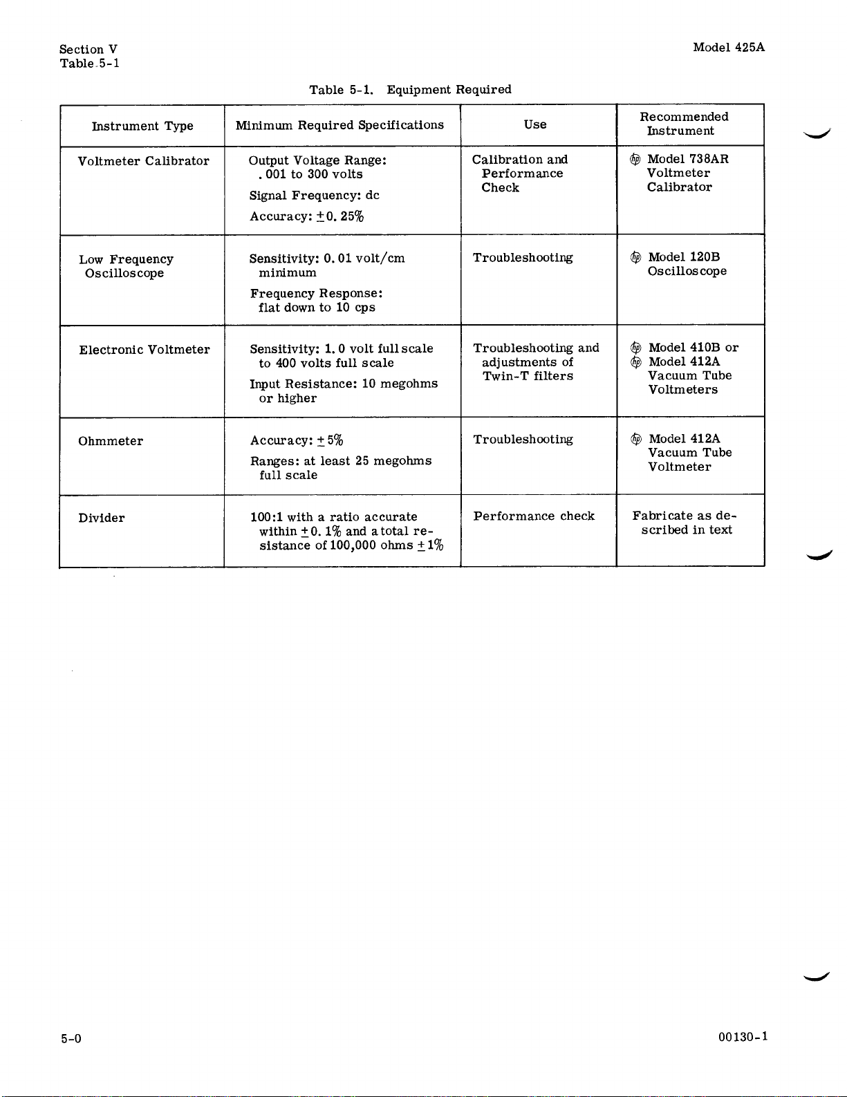
Table
5-1
.Equipment
Required
425A
Instrument
Voltmeter
Low
Frequency
Oscilloscope
Electronic
Ohmmeter
Divider
Type
Calibrator
Voltmeter
Minimum
Output
Signal
Accuracy:±0.25%
Sensitivity:0.01
Frequency
Sensitivity:1
Input
Accuracy:±
Ranges:at
100:1witharatio
Required
Voltage
.
001to300
Frequency
minimum
Response
flat
down
to 10
to
400
volts
Resistance
or
higher
least
full
scale
within±0.1%
sistanceof100,000
Specifications
Range
volts
do
volt/cm
cps
0
volt
.
full
scale
10
5%
25
accurate
andatotal
:
:
full
scale
megohms
megohms
re-
ohms+1%
Use
Calibration
Performance
Check
Troubleshooting
Troubleshooting
adjustments
Twin-T
Troubleshooting
Performance
and
filters
and
of
check
Recommended
Instrument
Model
Cep
Voltmeter
Cep
Chp
Fabricateasde-
scribedintext
738AR
Calibrator
Model
120B
Oscilloscope
410B
Model
Model
412A
Vacuum
Voltmeters
Model
Vacuum
Voltmeter
Tube
412A
Tube
or
Page 16

Model
425A
Paragraphs
Section
5-1
to
V
5-14
.
INTRODUCTION
5-1
5-2.This
information
performance
maybe
ifications
strument
recommended
and
adjustment
5-3.TEST
5-4
.GENERAL
in
table
fabricated
5-5
.100:1DIVIDER
voltage
andatotal
5-9)
.Manganin
sistors
thermal
5-6.MECHANICAL
METER
5-7
.When
over
the
when
instrumentis1)atnormal
ture,
2) in
off
.Zero-set
mechanical
section contains
for
Model
checkisincluded
used
toverifyoperationwithinpublished
.This
in
its
cabinet
test
procedures
EQUIPMENT
.
5-1
.Note
.
divider,
and
gradients
zero
witharatio
resistanceof100,000
wire
the
divider
.
ZERO
meter
calibration
its
normal
as
followstoobtain
stability
.
425A
check
.This
equipment,
Required
that
.
Fabricate
should be
ADJUSTMENT
.
isproperlyzero-set,
operating
:
test
Microvolt-Ammeter
(paragraph
should
some
be
section also includes
troubleshooting,
.
.
test
equipment
equipment
accurate
ohmsf1%
specified
assembly
mark
on
operating
position,
and
maintenance
made
with
needstobe
one
100:1resistive
withint0.1°
for the re-
should
OF
pointer
the
meter
and3)turned
best
accuracy
SECTION
MAINTENANCE
.
A
5-46)
that
spec
the in-
repair
is
listed
/n,
(see
figure
minimize
rests
scale
tempera-
and
V
reveal
ponent
table
have
shooting,
causes
5-11.AMPLIFIER-POWER
5-12.Amplifier
checkedbyvoltage-resistance
stitution.If
difficulty,
Voltages
these
from
5-13.CHOPPER
5-14
checked,itmust
bly,
locationofpartsinthe
follows
glow
tion of
blades
the
areaofthe
itself.To
5-2
andavoltage-resistance
been
included
gives a
.
return
and
are
typical voltages
instrumenttoinstrument
.
Before
A6,isworking
:
a.Remove
b.Check
whenpower
c
.Check
the
are
all
the
chopper
rotating
further
in this
listofsymptoms
and
tube
substitution
the
resistances
ASSEMBLY
the
modulator
bedetermined
properly.Refertofigure
cabinet
four
lamps
is
applied
light
assembly
.
faulty
section.Table
power
original
are
following
(paragraph
interrupterinthe cut
componentifnot
assistintroubleshooting,
chart
and
SUPPLY
supply
tubetothe
indicated
and
.
.
or
(D51-4)tomake
.
.
operation
readings
does
not
may
vary
demodulator
if
chopper
the
steps.Proceed
5-23)
to
seeifthe
figure
5-2,
their
andtube
correct
instrument
infigure
somewhat
.
sure they
away
the
com-
5-11
Trouble-
possible
is
best
sub-
5-11
can
assem-
5-1
por-
chopper
the
.
;
be
for
as
a.Allow
minutes;this
operating
b
.Turn
capacitorstodischarge
c.Rotate
wise
until
upscale
d.Continue
stop
when
shoots
e.When
ment
wise
.Thisisenoughtofree
the
meter
step
you
5-S.TROUBLESHOOTING
5-9.INTRODUCTION
5-10.The
in
the
many
00130-3
the
allows
temperature
instrument
mechanical
meter
toward
zero,
screw
must
localizing
cases
zero
to
pointer
repeat
pointerisexactly
approximately
suspension
repeat
following
visual
a
instrument
pointer
.
rotate
is
of
to
operate
meter
movement
.
off
and
allow30seconds
.
zero-adjustment
is to
leftofzero
adjustment
rightonzero.If
stepscandd.
on zero,
15
degrees
adjustment
.If
pointer
steps c
section
troublesinthe
inspectiono£the
.
throughe.
.
gives
informationtoaid
for
to
reach
screw
and
screw
pointer
rotate
counterclock-
screw
moves
Model
instrument
at
least20
normal
for
clock-
moving
clockwise
over-
adjust-
from
during
425A.In
all
this
will
;
L
D-5-618
Figure
5-1.A6,
Chopper
Assembly
Page 17

Section
Paragraphs
V
Meter
but respondstoZERO
Meter
signal
to
bias
Meter
signalorZERO
only
.
Meter
Meter
Excessive
5-15to5-16
SYMPTOM
failstorespondtoinput
control
.
failstorespondtoeither
or
ZERO
control,
control
failstorespondtoeither
driven
driven
.
controlonone
off
negative
off
positive
noise indicatedonmeter
but
responds
endofscale
endofscale
signal,
input
input
range
Table
.
.
.
.
Troubleshooting
5-2
POSSIBLE
Probe
assembly
INPUT
Cable
Modulator
V1
Modulator
Demodulatorassembly
ContactonsectionDof
LossofB+
V3
Grid-cathode
V5
VI
Poor
Noisy
from
and/or
heater
open
noisy
contact
breakdown
connector
.
.
defective
defective
INPUT
assembly
V2
assembly
.
open
connectortomodular
defective
and/or
.
shortinV3B
betweenVlpins
diode,
CAUSE
.
.
V3
defective
defective
defective
RANGE
.
CR1
.
.
.
.
switch
and
socket contacts
or
CR2
defective
defective
.
Model425A
.
.
.
Instrument
meter
has
ranges,
three
lowest
Meter
responsevery
Meter
responsetoZERO
itedtopositive
Onaparticular
zero
with no
exhibits
butitoperates
adjacent
d.If
the
chopperblades
motor
If
shaft
5-15.MODULATOR
5-16.To
follows
operation
Bl
is
operating,
If
.
not,
:
a.Remove
b.Remove
c
.
FUNCTION
Set
d.Set
RANGE
check
operates
slight
zero
large
switching
ranges
.
sideofzero
range,
input
abnormally
check
cabinet
cover
normally
ranges
.
indicatorinthe
chopper
the
6.3
the
ASSEMBLY
modulator
(paragraph
plate
switch
switchto1MA.
normally
offsetonhigher
sluggish
meter
and
high
are
volt
from
to
except
transients
.
control
.
drifts
instrument
sensitivity,
on
the
not
turning,
back
blade
circuittothe
.
operation,
5-23)
input-circuit
VOLTAGE
on
lim-
off
two
look at the
of
motor
looseonits
is
proceed
.
.
.
motor
B1
as
Bias
adjustment
R47
open
.
Weak
amplifier tubes
Demodulator
Chopper
CRl
ContactonSectionAof
Corresponding
.
.
volts
connected
oscilloscopetoinner
assembly
a
pedance
peak-to-peak
signal
coverofinput-circuit
light
shorted
e.Connect
.
f.Connect
g.Energize
typical
voltage
h.Disconnect
incorrect
assembly
misaligned
.
range
probe
an
to
circuit
Model
output
waveform
of1megohm
amplitudeapproximately
and
test
.
. .
defective
.
RANGE
resistor
toado
oscilloscopetopoint
board.Connect
chassis.See
425A
on
oscilloscope
on
oscilloscope
.
The
frequency
signal
assembly
.
switch
open
signal
and
waveform
5/6
and
defective
.
between1and
where
common
figure
observe
.
power-line
oscilloscope.Replace
.
5-2
modulator
Figure 5-3
having
should
equaltotest
frequency
.
lead
.
input
C4
shows
im-
have
5
is
of
.
5-2
00130-3
Page 18

Model
INNER
CHASSIS
425A
REAR
SECURING MOUNTING
COLLARS
Figure 5-2
SCREWS
CONNECT
.Modulator
OSCILLOSCOPE
HERE
Assembly
Section
of1megohm
amplitude
and
frequency
located on
.
.
A4,asa
components
modulator
end
closesttoVl
pink
(to
screws
are
located
enter
input-circuit
5-17to5-25
.
repair
the
which
Paragraphs
on
oscilloscope
Waveform
C4
imately
equaltotest
power-line
5-20
.
REPAIR
5-21.INTRODUCTION
.
5-22
This
lems
in the
5-23.CABINET
a.Remove
of
cabinet
b.Slide
remains
ring
5-24.MODULATOR
5-25
.Replace
do
not
attempttorepair
figure
bly
5-2
DisconnectC4
a
.
circuit
the following order,
brown,
point),
letters
red,
yellow,
along
b.Remove
assembly
and
below
container
having
should
frequency
have
peak-to-peak
signal
.
AND
input
impedance
voltage
REPLACEMENT
.
sectionisintendedtosimplify
Model
the
425A
REMOVAL
two
retaining
.
.
screws
.
iDstrument
attachedtofront
forward
outofcabinet
panel
REPLACEMENT
the
modulatorassembly,
individual
and
proceed
as follows
:
andleadsfrom
board;they
C4,
black, black,
starting
orange,
are
connectedtothe
from
input
and
and
black.(Note
edgeofboard.)
the
two
mounting
in
place.These
two
plastic
from
rear
.
rods
screws
which
approx-
5/6
prob-
rear
.Bezel
unit
.See
assem-
board
same
coded
hold
above
V
.
;
in
:
.To
check
outlinedinparagraph
5-17
instructions
5-18.DEMODULATOR
5-19.To
follows
a.Remove
b.Locate
straight
tor
board
c.Remove
sembly.The
terminals
check
:
back
(see figure
in
cabinet
demodulator
from
all
leads
the
lead)toterminal
white
(one
lead)tomiddle
to
terminal
d
.Connect
assembly
e.Connect
and
either
present
measurement
f
.
oscilloscope
(the
outer
a do path
Energize
nearest
adc
two
oscilloscope
.
.Figure
modulator
input
resistance
5-52
ASSEMBLY
demodulator
(paragraph
operation,
5-23)
assembly
the
RANGE
5-4)
connectedtoterminalsofas-
leads
color-coded
are
following
farthest
switch
.
order
frommain
:
purple-white
terminal;and
main
voltage
outer
chassis
between
terminals)
.
land.5volts
.
between
terminal.Oscilloscope
between
Model
its
input
425A
and
5-3
showsatypical
terminals
observe
follow
.
.
proceed
.
.
Itismounted
abovearesis-
and connected
chassis;blue-
blue (one
middle
terminal
must
for
waveform
waveform
the
(one
lead)
across
not
this
as
on
to
Figure5-3
.Modulator
G-S-45
Waveform
00130-4
5-
3
Page 19

Section
Paragraphs
V
5-26to5-29
Model
425A
c
.
Carefully
force
it
moval
securing
instrument
with
rodsifthey
cuit
paragraph
5-4
out,
.
If
d.Place
the
two
e.Connect
board
Use
heat
Cleanboard
finished
f
.
Check
lift
for
you
must
collars
.
new
mounting
were
external leads
.Use
small
soldering
when
.
Be
new
5-15
.
out the
the
and
assembly
moved
only
solderingtothe
carefully
suretoremove
modulator
modulator
plastic
move
slide
screws.Reposition
rosin-core
the rods,
.
Note
iron
rods
the
in
position
and
and
and
assembly
Figure
assembly
may
hinder
spread
rods
toward
and
C4
to
assembly
solder
.
apply
minimum
circuit
thoroughly
all
solder
as
5-4
.Right
;donot
its
their
rear
secure
the
plastic
board
when
flux
described
.
.
re-
rear
cir-
in
of
it
Side
View
5-26.DEMODULATOR
5-27.To
as
follows
a.Disconnect
b.Remove
assembly
instrument
c.Place
with the
d.Reconnect
5-28
5-29
wire
switch
rect
paragraph
Model
425A
replace
:
the
in
place
.
new
two
mounting
.
RANGE
.Figure5-5
destinations
.The
calibration
5-46
SWITCH
Model
.)
REPLACEMENT
demodulator
the
three
leadstothe
two
mounting
;
remove
assembly
the
three leadstothe
shows
for the
425A
after
the
in
screws
REPLACEMENT
the
replacement
shouldbechecked
replacing
.
assembly,
demodulator
screws
demodulator
position
.
locationofall
this
and
demodulator
.
of
switch
A5,
which
parts
the
proceed
from
secure
RANGE
for
.(See
00130-3
.
hold
the
it
.
and
cor-
Page 20

Model
425A
Section
V
Figure 5-5
GROUND
00130-3
Figure
5-5.Range
Switch Detail
YEL-RED
GRN-ORN
BLK-WHT
MODULATOR
TO
TO
SI
TO
A4
PIN
3OFVI
LD-M-578
5-5
Page 21

Section
Paragraphs
V
5-30to5-41
5-30.DISCONNECTING
RESISTOR
.
On
5-31
ped
from
resistor
ing
resistance
megohms
performed
special order,
the
on
.
factory with
disconnected
of
the
all
voltage
in
the
Calibrationofthe
of
the
modified
the
inputisexternally
megohm
5-32.To
as
follows
a.Remove
b.Remove
assembly
c
.Locate
ulator
assembly
the
stripislocated
the
undersideofthe
d
.Cut
not cut
diately
razor
as
a
TO
RESISTOR,
OF
resistor
disconnect
:
.
theindicated
the
narrow
into
the
around
blade
DISCONNECT
REMOVE
CONDUCTOR
cabinet
the
circuit
eyeletsofconducting
the
.
INPUT-SHUNTING
the
Model
the1megohm
from
the
modified
instrument
ranges.Modification
field
.
Note
nine
lowest current
instrumentisaltered
shunted
.
input-shunting
(paragraph 5-23)
cover
plate
from
conductor
boardinfigure
between
board
conducting
two
.
leads
stripateach
leads.Useasharp
INPUT
THIS
SHUNTING
STRIP
425A
willbe
input-shunt-
circuit.Input
exceeds
ranges
unless
with a 1.0
resistor,
proceed
.
the
input-circuit
strip
onthe
5-5.Note
coming
end.Do
material
cutting
tool
ship-
can
mod-
that
from
imme-
such
100
be
e
.
Lift
out the
Be
careful nottolift
material
off
the
narrow
board
5-33.REPLACEMENT
RESISTOR
5-34.The
in
the
instrument
whetheratthe
.
input-shunting
when
factoryorin the
instrumenttostandard,
a.Remove
b.Remove
assembly
c.Locate
assembly
d
.Connect
wire
.Solder
solder
.
5-35.SERVICING
Excessive
conductors
5-36.To
on
component
then be
or the leads
moved,
(metal
clean
awlsorsoldering
conductor)
cabinet
the
cover
.
the indicated
circuit
boardinfigure 5-6
these
two
both
ends
ETCHED
heat or
from
remove
components
sideofboard.New
solderedtothe
can
be
removed
holes with a toothpick or
before
inserting leads
stripofconducting
anyofthe
remaining
.
OF
INPUT-SHUNTING
resistor
the
modification
field.To
proceed
as follows
(paragraph
plate
from
points
points
with a
neatly,
using
CIRCUIT
Note
pressure
etched
circuit
from
leads
extending
.
If
aids
may
.
Model
remains
restore
5-23)
.
the
input-circuit
on
the
.
pieceofcopper
only
BOARDS
can
lift
copper
boards
board,
components
from
the
leads
wooden
destroy
425A
material
conducting
physically
is
made,
the
:
modulator
rosin
core
.
.
leads
clip
can
the
board
are
re-
splinter
the
copper
.
TO
RECONNECT
RESISTOR,
POINTS
Figure
Input-Shunting
5-6
INPUT
CONNECT
.
Connection
SHUNTING
THESE
Point
Resistor
TWO
of
MP-S-1131
5-37.ADJUSTMENTS
5-38.INTRODUCTION
5-39.The
ment
been
of
adjustment
following
procedure
definitely
and
determined
.
5-40.ADJUSTMENT
F
OLLOWER
5-41.The
when
the
cathode
Model
425Aisreceived
alcheckisnecessary
Turn
a
.
b.Set
c.Set
d.Observe
(+5%oofend
e.If
adjust
ure
5-4),toapproximately
response
instrumenton.
FUNCTION
RANGE
meter
scale)
the
meter
R47,
BIAS
to this
does
adjustment
adjustment
.
.
section
should
OF
BIAS
follower
be
that
CATHODE
.
bias
isacomplete
the
thereafter
Allow15minutes
switchtoVOLTAGE
switch
to
.003
.Ifitreads
the
checkiscomplete
not
read
potentiometer
zero
is
slow
made
only
Model
425Aisout
should
.
Onlyan
be
.
.
MILLIAMPERES
approximately
.
approximately
meter.The
.
adjust-
if it
has
checked
occasion-
warmup
zero
zero,
(see
fig-
meter
.
.
5-6
00130-
3
Page 22

Model
425A
Paragraphs
Section
5-42to5-43
V
5-42.ADJUSTMENT
5-43
.The
in unit
filter
line
may
a.Remove
filter,
b.Connect
between
source
line
power
determinedby
Parts
00130-
twin
which
for
remove
for an
frequency
line
tableinSectionVI.
4
should
eithera60
be adjustedasfollows
two
aharmonic-free
pins 6
frequency
Figure 5-7
OFTWIN-T
filters
screws
cover
and8(ground)offilter.Set
output
for
which
stock
containedina
are
be
removed
cps
power
holding shield-cover
and
pull
frequency
filterisdesigned
foraparticular
number
FILTERS
single
for
adjustment
a
line
:
filter
sinewave
which
as
showninReplaceable
50
or
outofsocket
signalsource
is
5/6ofpower
filter
.Left
.
plug-
.
cps
power
over
signal
.Correct
may
be
.
A
Side
View
c.Connectanoscilloscope or
7
and8of
amplitude
least
d.Maximum
nately adjusting
for
e.Connect
pins3and8on
Model
425A
Instrument
test
signalisnot set
to
correct
filter.Compare
of
60 db
.
minimum
performance
frequency
applied
attenuation
R39
output
between
same
test
filter
Note
may
be
degraded
as
closely as possible
.
vtvm
ac
signal
signal.Attenuation
andR41
signal
.
amplitude here
may
be
obtainedbyalter-
(blue-colored
pins 7
and8.
usedinstep
between
must
controls)
b
between
if
pins
with
be
at
5-7
Page 23

Section
V
Paragraphs
f .
Connect
and8of
amplitude
least
60 db
g.Maximum
nately
for
adjusting
minimum
h.Plug
cover
.
5-44to5-51
filter
.Compare
of
applied
.
output
filter
oscilloscope
signal
attenuation
R50
and
between
unit into
or ac
vtvm
between
signal
amplitude
.Attenuation
may
be obtainedbyalter-
R52
(red-colored
pins 2
and8.
socket
and
replace
pins 2
here
must
be
controls)
shield
Model425A
with
at
5-44.METER
5-45.To
a.Remove
b.Set
paragraph
c.Turn
warmup
.
d.Check
paragraph
e.Set
f.Set
.
Connect
g
h.Adjust
meter
pointertoexactly+1.0.
i.To
Voltmeter
calibrate
cabinet
mechanical
the
5-6)
.
the
cathode
5-40)
FUNCTION
RANGE
probe
R67
check
Check
CALIBRATION
instrument
.
the
5-46.PERFORMANCE
5-47.INTRODUCTION
.
The
the
instrument
asafinal
following
Model
incoming
Adjustment
5-48
operationofthe
with
be
made
partofthe
complete
5-36
.
.
theModel
(see
425A
paragraph
proceedasfollows
5-23)
adjustmentofmeter
on
and
allow
follower bias
adjustment
switchtoVOLTAGE
1-volt
volt
range
f1%
see
.
do
source
paragraph
switch
to
to
1.0
METER
calibration,
CAL.(see figure 5-4)toset
.
CHECK
.
procedure
425A
the
in
test
for routine
quality
istoverify
and
shouldbeperformed
cabinet.This
maintenance
control inspection
Procedureisgiveninparagraph
.
15
.
check
zero
minutes
.
5-49,
proper
or as
.A
(see
(see
may
:
Figure
g
.Zero
trol
.If
graph
h.Check
rangesby
and
calibrator
IBRATE
will
i.Set
to
DC+,
PLIER
j.Connect
using
5-8.Voltmeter
(1
VOLTS
Model
3-8
meter
.
through.3
of
Model
425A
the1VOLTS
setting
Model
425A
switchesofthe
as
shown
FUNCTION
position.The
remain
in
the
VOLTAGE
voltmeter
FUNCTION
switch
to0,and
Model
the
100:1dividerasshowninfigure
Calibration
MILLIVOLTS
425A
cannot
be zeroed,
through0.3MILLIVOLTS
intable
switch
Mode1425A
calibrator
switchtoCALIBRATE,
RANGE
425A
with
voltmeter
will
position
OUTPUT
switchto1
to
voltmeter
MICROVOLT-
Test
ranges)
panel
ZERO
refertopara-
5-3.The
remaininthe
FUNCTION
.
SELECTOR
5-9
MODEL
AMMETER
Setup
con
calibrator
voltmeter
CAL-
switch
MULTI-
.
calibrator
.
425A
VOLTMETER
5-49
.
5-50.CALIBRATION
as follows
a
.Adjust
5-6)
b.Adjust
5-40)
c.Turn
half-hour
d.Set
to
DC+,
PLIER
e.Connect
:
mechanical
.
Cathode
.
voltmeter
warmup
voltmeter
FUNCTION
switchto0,
Model
showninfigure
f
.Set
Model
and
RANGE
switch
5-8
CHECK
.
.Tocheck
meter
Follower Bias
calibrator
.
calibrator
switchtoCALIBRATE,
and
RANGE
425Atovoltmeter
5-8
.
425A
FUNCTION
to 10
MICROVOLTS
calibration,
zero (see
(see
on
and
OUTPUT
switchto1
switchto
.
proceed
paragraph
paragraph
allowaone-
SELECTOR
MULTI-
.
calibrator
VOLTAGE
as
Figure
(100
MICROVOLTS
k.Repeat
m.Check
VOLTS
ranges
calibrator
voltmeter
the
CALIBRATE
switch
will
5-51.METER
ing,
proceed
a.Connect
as
shown
5-9
.Voltmeter
through10MICROVOLTS
stepsfandg.
100
MICROVOLTS
by
setting
and
Mode1425A
calibrator
FUNCTION
position.The
remain
in
TRACKING
as follows
Model425Atothe
in
figure
5-8
the
:
.
VOLTAGE
.Tocheck
Calibration
through
the
switches
as
shown
switch
Model
voltmeter
Test
10
of
intable
willremainin
425A
FUNCTION
position
the
meter
Setup
ranges)
MICRO-
voltmeter
5-4.The
.
track-
calibrator
00130-
4
Page 24

Model
425A
(1
Table
VOLTS
5-3.Voltmeter
through.3
MILLIVOLTS
Calibration
ranges)
Section
Paragraph
V
5-52
OUTPUT
SELECTOR
DC+
DCDC+
DCDC+
DC-
DC+
DCDC+
DCDC+
DCDC+
DCDC+
DC-
b.Set
and
voltmeter
TRACKING,
d.Reduce
volt
meter
e.Check
voltmeter
f.Reduce
stepsbyrotating
should
5-52.INPUT
pedance,
Model
RANGE
c.Check
stepsbyrotating
switch
the
calibrator
and
should
the
calibrator
voltmeter
indicate
proceed
the
indicate
IMPEDANCE
425A
FUNCTION
to1VOLTS
positive
FUNCTION
OUTPUT
voltmeter
TRACKING
negative
OUTPUT
the
TRACKING
TRACKING
as
follows
Voltmeter
section
SELECTOR
the
sectiontracking bysettingthe
calibrator
.
Calibrator
MULTIPLIER
1
.
1
.
.1
.1
.1
.1
.01
.01
.01
.01
.001
.001
.001
.001
.001
.001
switchtoVOLTAGE,
.
trackingbysetting
switch
to
calibrator
TRACKING
SELECTOR
voltages
To
:
outputin0.1control
voltages
output
control.The
+3%
.
check
the
to
1
VOLTS
DC+
.
. The
±3%
.
to
DC-
in 0.1-volt
meter
input
im-
the
.
RANGE
(VOLTS)
1
1
3
3
1
1
3
3
1
1
3
3
1
1 1
.
3
.
3
a.Connecta1M±0.1%resistor
of
calibrator
b.Set
c
DC+,
to2.
d
ZERO
e
1
position
f.The
within
425A
.3VOLT
.3VOLT
.1VOLT
.1VOLT
30
30
10
10
3
3
1
.3MILLIVOLT
.3MILLIVOLT
Model
425A
.
Model
.
Setvoltmeter
MULTIPLIER
.Zero
control
.
Set
voltmeter
.
Model
0 .03
meets
Model
425A
RANGE
I
VOLTS
1
VOLTS
MILLIVOLTS
MILLIVOLTS
MILLIVOLTS
MILLIVOLTS
MILLIVOLTS
MILLIVOLTS
MILLIVOLTS +1
MILLIVOLTS
and
the
upper
terminal
425A
RANGE
calibrator
switchto0,
meterofModel
.
calibrator
425A
volts.This
its1megohm
425A
meter
check determines
+3%
Meter
(+3%of
betweenthe probe
of the
switch
OUTPUT
and
RANGE
with
the
MULTIPLIER
should
specification
indicate
Reading
end
scale)
1
+
-
1
+3
-3
+1
-1
+
3
-
3
1
+
- 1
+
3
- 3
-1
3
+
-
3
voltmeter
to 1
VOLTS
SELECTOR
front
if
the
.
to
switch
panel
to
the
1
volt
Model
.
00130-
OUTPUT
SELECTOR
DC+
DC-
DC+
DCDC+
DC-
2
(100
Voltmeter
MULTIPLIER
Table
MICROVOLTS
Calibrator
.01
.01
.001
.001
.001
.001
5-4.Voltmeter
through10MICROVOLTS
RANGE
(VOLTS)
Calibration
1
1
3
3
1
1
RANGE
100
MICROVOLTS
100
MICROVOLTS
30
MICROVOLTS
30
MICROVOLTS
10
MICROVOLTS
10
MICROVOLTS
ranges)
Model
425A
Meter
(±3%
of
+
-1
+
- 3
+
- 1
Reading
end
scale)
1
3
1
5-9
Page 25

Section
Paragraph
OUTPUT
SELECTOR
DC+
DC-
DC+
DC-
DC+
DCDC+
DCDC+
DCDC+
DCDC+
DCDC+
DCDC+
DCDC+
DCDC+
DCDC+
DCDC+
DC-
V
5-53
Voltmeter
Calibrator
MULTIPLIER
100
100
100
100
100
100
100
100
10
10
10
10
1 3
1 3
1 1
1 1
.
.
.
.
.01
.01
.O1
.01
.001
.001
Table
RANGE
(VOLTS)
1 3
1
1
1
5-5.Ammeter
3
3
3
3
3
3
1
1
3
3
1
1
3
1
1
3
3
1
1
3
3
Series
Resistance
Resistance
100K
100K
300K
300K
1M
1M
1M
1M
1M
1M
1M
1M
1M
1M
1M
1M
997K
997K
990K
990K
967K
967K
900K
900K
667K
667K
Calibration
3
MILLIAMPERES
3
MILLIAMPERES
1
MILLIAMPERES
1
MILLIAMPERES
.3
MILLIAMPERE
.3MILLIAMPERE
.1MILLIAMPERE
1
MILLIAMPERE
.
.03
MILLIAMPERE
.03
MILLIAMPERE
01
MILLIAMPERE
.01MILLIAMPERE
.003
MILLIAMPERE
.003
MILLIAMPERE
1
MICROAMPERES
1
MICROAMPERES
MICROAMPERE
.3
.3MICROAMPERE
.1MICROAMPERE
.1MICROAMPERE
30
MILLI-MICROAMPERES
30
MILLI-MICROAMPERES
10
MILLI-MICROAMPERES
10
MILLI-MICROAMPERES
3
MILLI-MICROAMPERES
3
MILLI-MICROAMPERES
RANGE
Model
425A
Meter
(+
3°%ofend
Model
Reading
+3
- 3
1
+
-1
+3
-
3
+1
- 1
+3
-
3
+1
- 1
+3
-
3
+1
-
1
+3
-
3
+
1
-
1
+3
-
3
+1
1
+3
3
-
425A
scale)
Note:The
are
measures
v C>
J
v
Figure
five
lowest current
checkedbythe input
the
IR dropacross
MODEL738AR
O
DD*P~T~
5-10
.Ammeter
impedance
IOOK-0
.1%
300K-0
.1%
1M=0
.1%
~
997
967K=0
900K-0
667K~-0
I/4W
.1%1/4W
.1%1/4W
Calibration
ranges(1MILLI-MICROAMPERES
check
and
the
voltmeter
the
IW
I/2W
one-megohm
425A
MICROVOLT-
AMMETER
Test
Setup
input
MODEL
LD-5-612
check
impedance
on
5-53.AMMETER
a.Setvoltmeter
b.Set
FUNCTION
switch
Model
DC+,
PLIER
the series
c.Connect
meter
of
Model
d.Check
CROAMPERES
switchesofthe
voltmeter
the
CALIBRATE
switch
calibrator
will
through
of
the
to 0,
10
MICRO-MICROAMPERES)
the
same
five
lowest
CHECK
calibrator
switch
and
RANGE
425Atothe
ranges.The
current
.
OUTPUT
to
CALIBRATE,
switchto3
voltmeter
Model
ranges
SELECTOR
calibrator
resistorsasshowninfigure 5-10
probe
to
667K
425A
3
MILLIAMPERES
ranges
test
position.The
remain
with the
of
circuitas
FUNCTION
in
the
CURRENT
resistor
panel
through3MILLI-MI-
Model
shownin
switch
Model425A
425A
and
ZERO
by
table
will
FUNCTION
position
425A
.
MULTI-
.
using
.
zero
control
setting
5-5.The
remain
.
to
the
.
the
in
5-10
00130-
2
Page 26

Model
425A
Section
Figure
V
5-11
Heavy
or
2
.
Heavy
3
.
Arrows
clockwise
4.Resistance
unless
5
.
Rotary
the switch
6
.
Relays
7
.
t
8
.
Interconnecting
9
.
*
solid
feedback
box
otherwise
shown
indicatesaselected
Value
SCHEMATIC
line
shows
path
.
indicates
on
potentiometers
from
the
values
specified
switch
adjustedatfactory.Part
schematics
assembly
in
parts
condition
main
front-panel
indicate
rectangular
in
ohms,
.
are
drawings
prevailing
part.See
andassemblies
signal
inductance
.
path;heavy
engraving;light
clockwise
shaft
end
.
in
electrical
during
parts
list
are
may
be
omitted
DIAGRAM
dashed
box
indicates
rotation
microhenries,
representations
normal
.
shown
on
.
as viewed
instrument
cable
NOTES
line
and
;
diagram
shows
chassis
from
capacitance
for
exact
operation
.
control,
marking
the
round
switching
.
secondary
.
shaft
end,
in
micromicrofarads
details
signal,
counter-
refer
to
1
.Each
as
follows
H
K
G
Sc
Sp
Hm
is
The
tube;the
like
A
socket
resistance
2
.
Voltagesvalues
normal
shownwhen
3
.
Voltage
ments
noted
tube
:
no
heater
cathode
control
screen
suppressor
heater
internal
numerical
letter
elements
terminal
differences
measured
made
.
VOLTAGE
socket
shown
the
terminal
tube
element
grid
grid
grid
mid-tap
shield
subscript
subscripttotube-element
in
the
.
shown
circuit
at
with
an
to
same
tube
with
an
are
between
contains
the
terminal
electronic
AND
is
numbered
tube-element
section,
asterisk
for
guidance;values
instruments
potentiometers,
is
multimeter,
RESISTANCE
and
letteredtoindicate
P
T
R
A
S
Sh
NC
designators
designators
such
astfor
may
be
used
may
.
Resistance
crystal diodes,
shown
above
from
DIAGRAM
indicates
indicates
triode
asatie
vary
values
the
line,
terminal
NOTES
the tube
plate
target
reflector
anode
spade
shield
no
indefinite
(plate)
(plate)
external
the
the
andpfor
point
from
those
may
or
resistance
to
chassis
element
or
repeller
connection
reading
vary
electrolytic
due
sectionofa
functional
pentode
and
may
shown
considerably
below
ground
and
pin
to
socket
to
circuit
difference
.
haveavoltage
due
capacitors
the
unless
(see
multiple-section
to
tube
aging
from
.
line;measure-
otherwise
number,
2
. )
between
and
those
or
4
00130-
.
A
solid
terminals;a
resistance
1
line
between
dotted
are
givenatonly
socket
line
terminals
between
oneofthe
indicatesaconnection
terminals
two
indicatesaconnection
joined
terminals
external to the
.
inside
tube
the
tube.Voltage
between
the
and
5-11
Page 27

425A
Section
Figure
V
5-11
Model
+I50V
(6X4)
V4
RECTIFIER
V6
(OA2)
REGULATOR
V3
"AMPLIFIER
CATHODE
+150V
(12AT7)
&
FOLLOWER
5-12
Figure
V2(12AX7)
AMPLIFIER
.Voltage
5-11
and
Resistance
Diagram
VI\
AMPLIFIER
(viewed
(5751)
from
bottom)
-e-158
LP
00130-
2
Page 28

Model
COPYRIGHT
425A
1957
BY
This
drawing
and
maintenance
andisnottobe used
ment
reproduced
Hewlett-Packard
425A
A4
-
DCM-TI42ABCD
MODULATOR
(PARTS
without
NOT
HEWLETT-PACKARD
intended
is
of
Hewlett-Packard
written
Company
SEPARATELY
for
the
operation
otherwise
consentofthe
.
INTERNAL
REPLACEABLE)
COMPANY
equip-
or
WIRING
INPUT
J1
VOLTS
"
w
~aa
-
CURRENT
Y
I
I
I
1
I
I
FUNCTION
C5A
20uF
RIB
405
K
C6
/N
.o1uF
I
I
I
I
I
_J
NE2
VRI
J
CI
WE
BRN
C2
.Iu-F
A4
MODULATOR
(SEE
DETAIL)
C4
005JIF
R86
10
.1
K
--I--VIA
VIA&B
5751
AMPLIFIER
I
0--wA---,
(6)
(7)0--
(e)O--NVr~
(s)
0-wvr-1
~
(10)
(12)
0--Vv-_i
500K
R2
IIIK
R3
34.5K
R4
IO
R5
3~340
R7
333
.IK
ORNIYEL
C3
IPF
~
~
~
~
~
R14
3300
--------
BL
K
-L4V
POWER
SUPPLY
-------
T1
00130-
DS
I
12
GE
~GE12
3
DS
a
2
Page 29

Section
Figure
-1-125
V
R34
VOLTS
CURRENT
(1)
_
(2)
13)
(4)
-~
(5-18)
1
I
I
I
I
I
I
I
I
I
I I
I
I
I
I
I
R19
2
.2M
R30
220
R22
560K
R2
270K
R24
150K
R25
47K
R26
15K
R27
4700
R28
1500
R29
470
(9)
Uo)
R31
680
R32
330
I
I
I
I
I
I
I
I
I
I
I
I
.3
.003
.01
.03
.1
.3
I
RANGE
~A
MV
A
MJJ
V
AA
MA
1
NOTE
ASSEMBLIES
ONE
REPLACED
R
4150V
-
tl25V
rERO
R80
M
R79
220K
-1.4V
R81
IM
O
S2
1-10
2
-30
3-100
4-3
5-1
6-3
7-10
B-30
9-1
1011-1
1213-
1415-
16-
17-
18-3
BI
47K
V2A
R37
a
B
470K
12AX7
C58-
R33
20(.LF
1
470K
I
AMPLIFIER
T
1
.047U
CIO
C9
.1(LF
F
I
CII
.01
u1`
6 6
I
V2A
I
R35 R36 R38 R46
5600
I
I
IOM
V2B
6
2
.2M>
I
I
I
i
384K-60ti-325K
319K-50'V-270K
71
I
I
I
OIPF
I
~1
(BLUE)R39
144K(60'V)
120K(50'W
,
TOOK
OI)JF
®
I
I
I
I
I
1
AI
I
I
I
02)1`
R41
IOOK
(BLUE)
I
VOLTS
"
R58
IM
R59
332K
R60
99K
R61
.3K
32
R62
9000
R63
2330
CONTAINER
v
(2
(3
"
(4,8)
(9)
(10)
(II)
AI8,A2
SEPARATELY
--
-
6)
7
a
CANNOT
(3)
(4)
ARE
,
"
2)
"
"
REF
DELETED
C12-14
C17-19
R17,40,42
4,3,51,53
54
IN
BE
;6
I
I
I
i
CATHODE
FOLLOWER
(5-18)
(1-4)
UNASSIGNED
R15,17
*150
V3A
lie
AMPLIFIER
R44
Iooo
V3B
I
i212AT7
C23
2200
DESIGNATORS
A1,2,4,5
BI
C1-31
CRI-
3
DSI-5
FI
JI- 2
MI
P1
RI-86
TI
SI-3
VI- 8
VRI
V
12AT7
I
3900
R64
9900
R65
100
;
IOOK
f
R45
6
4285V
255
L
--
-//V
V
C16 -I-
.027UFT
R47
IOK
R55
C21
.27PF
I
R85
1000
R66 R68
2200 500
R67
2000
METER
CAL
R48
6.8M
-//
C20
2UF
~p
-1
I
BIAS
V
C221
JIJF~
I
R56
I
182K
INo
M M
(1)
I
T
I
I
.
384K-60'L-325K
319K-50r\-
N
144K(60'L)
(34
0I
680K
R69
5000
MI
270K
120
K(5OrU)
024F
R52
IOOK
(RED)
C271
.033
uF
(4-18)
OUTPUT
AMPLITUDE
EL
R70
IOK
00425-D-
V
5-12
(RED)
C28
I4F
14
M
J2
3
Figure
5-12
.Model
425A
DC
Microvolt-Ammeter
5-13
Page 30
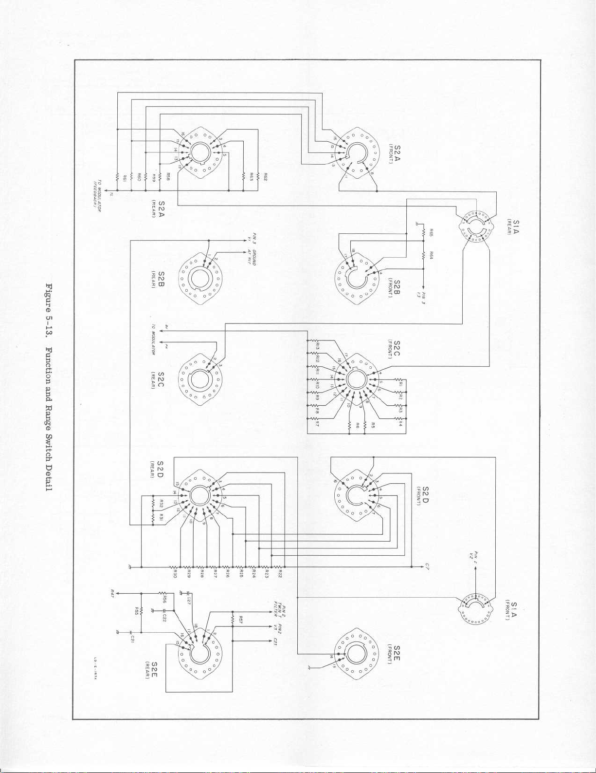
as
G
K
CD
r
w
G
C7
rt
O
C~.
CD
w
rt
O
d
CD
r
Page 31

Section
Figure
V
5-13
and
am
N
LO Cn
Figure
LO
Q)
5-14
425A
Model
W
LLJ
W
N
UJWHX
a
Q
Z<
J
LC)
I'
z
_Z
MC)CL
CO
U
m
0
O
a
A
0
0
0
0
cd
5-14
00130-2
Page 32

F
FL
J
K
L
M
MP
Ge
h
Hg
K
m
M
ma
4
td
w/
W
ww
*
Model
425A
INTRODUCTION
6-1
.
6-2
.This
replacement
numerical
indicates
part,
together
lists
parts
numbers
each
part
section contains
parts
orderoftheir
description
the
with
alpha-numerical
in
and
provides
:
a.Descriptionofthe
below)
.
b
.Typical
code;see
manufacturer
listofmanufacturers
c.Manufacturer's
d.Total
quantity
.
.Table
any
applicable
the following
part
stock
used
inthe
REPLACEABLE
information
6-1
lists
parts
reference
andQ)stock
(see
of
number
instrument(TQ
designators
number
notes
orderoftheirQ)stock
information
listofabbreviations
the
partina
appendix
in
.
SECTION
for
ordering
in
of
.Table
five-digit
.
column)
alpha-
and
each
6-2
on
Paragraphs
Section
6-1to6-7
VI
VI
PARTS
for
order
office
.
each
6-1are
or
(see
part
:
.
6-3.Miscellaneous
listedatthe
endofTable
6-4.ORDERING
6-5.To
orderareplacement
inquirytoyour
mapatrearofthis
6-6
.Specify
Model
a
.
b
.
and
Hewlett-Packard
c.Circuit
.
d.Description
parts
INFORMATION
local
Hewlett-Packard
manual
the
following
complete
reference
.
not
indexedinTable
6-2
.
for
information
serial
stock
number
designator
.
part,
address
field
addresses)
numberofinstrument
.
.
e.Recommended
maintenance
(RS
column)
A=
B=
C=
CR=
DL
DS=
E=
a=
by=
bwo=backward
c=
cer=ceramic
cmo=
coef=coefficient
com=common
comp=composition
conn=connection
crt=
dap=
EIA
.y.
°
.'
o
.
assembly
motor
capacitor
diode
=
delay
line
device
signaling
misc
electronic
amperes
bandpass
oscillator
carbon
cabinet
cathode-ray
deposited
=
Tubesortransistors
meeting
Industries'
tion
standards
normally
instrument
within
tubes
and
selected for best
performance
suppliedifordered
by~stock
spare
during
(lamp)
part
wave
only
mount
tube
Electronic
Associa-
will
result
in
operating
specifications
transistors
will
be
numbers
one
.
6-7
.To
part
year
quantity
of
for
isolated
complete
service
give
function
REFERENCE
= fuse
=
filter
= jack
=
relay
= inductor
=
meter
=
mechanical
elect=electrolytic
encapsulated
encap=
= farads
f
fxd= fixed
=
germanium
grd=
ground
henries
=
=
mercury
impg=impregnated
incd =
incandescent
ins=
insulation
=
kilo
lin= linear
log=
logarithmictaper
=
;
milli
=
megohms
=
milliamperes
=
micro=10-6
minat=
miniature
mfgl=metal
mfr=
manufacturer
part
(ed)
(ed)
= 1000
taper
3
= 10
film on glass
DESIGNATORS
ABBREVIATIONS
P=
Q=
R= resistor
RT=
S=
T=
mtg=mounting
my=
NC=
Ne=
NO=
NPO
nsr= not
obd=
p=
pc=
pf=
pp
piv
pos=
poly
pot=
rect=rectifier
orderapart
a
complete
and
location
plug
transistor
thermistor
switch
transformer
mylar
normally
neon
normally
negative positive
=
(zero
temperature
coefficient)
separately
replaceable
orderbyde-
scription
peak
printed
board
picofarads
-12
1012farads
peak-to-peak
peak
inverse
voltage
position(s)
polystyrene
=
potentiometer
closed
open
circuit
not
listedinTables
descriptionofthe part
.
V=
W=
X=
XF=
XDS=lampholder
Z=
rot= rotary
rms=root-mean-square
rmo=rack
s-b=
Se=
zero
=
sect =
Si=
sil=
sl=
TiO
2 =
tog=
tol=
trim
twt= traveling
var=
who
6-1
and
and
include
vacuum
tube,
bulb,
photocell,
cable
socket
fuseholder
network
mount
only
slow-blow
selenium
section(s)
silicon
silver
slide
=
time
delay
titanium dioxide
toggle
tolerance
=
trimmer
variable
=
with
=
watts
=
wirewound
= without
optimum
=
selectedatfactory,
average
shown
be omitted)
value
value
(part
wave
may
6-2,
its
neon
etc
tube
.
00130-1
Page 33

Section
Table
Circuit
Reference
Al,
A3
A4
A5
VI
-6-1
A2
(~W
StockNo.
9110-0039
9110-0038
425A-58B
425A-23C
425A-23B
Table
6-1
.
Index
Assy,
For
For
Assy,
A4
C1
C6thruC8
CRl,CR2
R14
Assy,
Assy,
V7,
by
Reference
Description
"T"
Twin
50
cycle
60
cycle
input
thru
C3
modulator
demodulator:includes,
V8,
XV7
Filter
power
power
amplifier:includes,
Designator
:
operation
operation
#
R18
R73
R81
VRl
thru
thru
Model425A
Note
R20
R79
A6
A7 425A-19A
B1
C1
thru
C3
C4
C5A/B
C6
C7
C8
C9
C10
C11
C12
thru
C14
425A-97A
3140-0013
0170-0030
0150-0014
0180-0012
0170-0017
0170-4021
0170-0017
0160-0013
0160-0005
0160-0054
Assy,
Assy, range
Motor,
C:fxd,
C:fxd,
C:fxd,
C:fxd,
C:fxd,
C:fxd,
C:fxd,
C
C:fxd,
Not
chopper:includes,
B1
DS2
thru
XD
S2
thru
Rl
thru
R22
thru
synchronous
poly,
cer,
elect,2sect,
my,
my,
my,
my,
fxd,
:
my,
paper,
assigned
DS5
XD
S5
switch
R13
R32
0.1pf
0.005
0.01 pf
4700
0.01gft5%,
0.1 pf
0.047
0.01 pf
:
includes,
type:6
±10%,
pf,
20
f5%,
pf
±10%,
t10%,
1Af
±10%,
50
500
vdcw
pf/sect,
400
400
400
400
f20%,
R57
S2
.3V,
vdcw
vdcw
vdcw
vdcw
600
400
AC
vdcw
vdcw
450
vdcw
vdcw
6-2
#
See
introduction
to this
section
00130-2
Page 34

Model
Reference
C15,
C17
C20
C21
C22
C23
C24
C25
C26A/B
C27
C28
C29,
C31
425A
Circuit
C16
thru
C30
C19
Table
(~W
StockNo.
0160-0026
0160-0030
0160-0039
0170-0019
0160-0007
0170-0022
0180-0024
0180-0028
0160-0004
0170-0022
0150-0073
6-1.Index
C:fxd,
Not
C:fxd,
C:fxd,
C
:
C:fxd,
C:fxd,
C:fxd,
C:fxd,
C:fxd,
C:fxd,
Not
C
:
by
Reference
my,
0.027 p.f±10%,
assigned
paper,2pf
my,
0.27 pf
fxd,
my,0.1
my,
2200
my,0.1
aluminum
elect,2sect,1.
my,0.033
my,0.1
assigned
fxd,
cer,
100
Designator
Description
±20%,
±10%,
1Af
t5%,
200
pf
±10%,
1Af
±20%,
elect,40pf,
lcf
1Af
±20%,
pf
f10%,
600
5K
f10%,
(Cont'd)
#
600
vdcw
200
vdcw
200
vdcw
vdcw
600
vdcw
vdcw
450
vdcw
/Af/sect,15vdcw
600
vdcw
600
vdcw
500
vdcw
Section
Table
Note
VI
6-1
CR1,
CR3
DS1
F1
J1
J2
J3
CR2
thru
DS5
G-29A-74
1882-0005
2140-0012
2110-0007
2110-0008
1250-0039
AC-76J
AC-10C
AC-10D
AC-54B
AC-54F
AC-76J
AC-10D
AC-54B
AC-54F
Diode,
Rectifier,
Lamp,
Fuse,
Fuse,
Connector,
Binding
Binding
Binding
Insulator
Insulator:outside
Rack
Binding
Binding
Insulator:inside
Insulator
zener
metallic
minat:0
cartridge:s-b,1amp
(for
115
V
operation)
cartridge
(for
230Voperation)
input
receptacle
post
post:black (rmo)
post:red
:
Mount
post
post:red
:
:
triaxial
and
inside
Only
and
outside
.15
amp,
s-b,
panel
ground
ground
6.3
V
1/2
amp
jack
:
link:black (cmo)
link:black
M1
00130-2
G-81E
#
Meter,
See
introduction
calibrated
to this
section
6-3
Page 35

Section
Table-6-1
VI
Table
Circuit
Reference
p1
Rl
R2
R3
R4
R5
R6
R7
R8 425A-26H
R9
R10
R11
R12
R13
R14
R15
(~W
Stock
8120-0050
0757-0015
0757-0013
0757-0008
425A-26A
425A-26D
425A-26F
425A-26G
425A-26I
425A-26J
425A-26K
425A-26L
425A-26M
0687-3321
6-1
No
.
.
Index
Cord,
R:fxd,
R:fxd,
R
:
R:ww
R
:
R:ww
R
:
R
:
R
:
R:ww
R
:
R
:
R
:
R
:
Not
by
Reference
power
mfgl,
mfgl,
fxd,
mfgl,34.5K
ww
ww
ww
ww
ww
ww
ww
fxd,
comp,3.3K
assigned
Designator
Description
500K
ohms
111K
ohms
ohms
ohms
(Cont'd)
#
fl/2%, 1/2
tl/2%, 1/2
fl/2%, 1/2
±10%,
1/2
Model
W
W
W
W
425A
Note
R16
R17
R18
R19
R20
R21
R22
R23
R24
R25
R26
R27
R28
R29
R30
R31
R32
R33
0687-6851
0727-0240
0687-2251
0687-4741
0687-1531
0687-5641
0687-2741
0687-1541
0687-4731
0687-1531
0687-4721
0687-1521
0687-4711
0687-2211
0687-6811
0687-3311
0687-4741
fxd,
R
:
Not
assigned
R:fxd,
fxd,
R
:
fxd,
R
:
R:fxd,
fxd,
R
:
R:fxd,
fxd,
R
:
R:fxd,
fxd,
R
:
fxd,
R
:
R:fxd,
fxd,
R
:
fxd,
R
:
fxd,
R
:
fxd,
R
:
R:fxd,
comp,6.
c,
dep
comp,2.2M
comp,
comp,
comp,
comp,
comp,150K
comp,
comp,
comp,4.7K
comp,1.5Kohms
comp,
comp,
comp,
comp,
comp,
405K
470K
15K
560K
270K
47K
15K
470
220
680
330
470K
8M
f10%,
ohms
f10%,
ohms
ohms
ohms
ohms
ohms
ohms
ohms
ohms
ohms
ohms
ohms
ohms
ohms
1/2
tl%,
1/2
±10%,
f10%,
±10%,
±10%,
±10%,
±10%,
±10%,
±10%,
±10%,
±10%,
±10%,
±10%,
±10%,
±10%,
W
1/2
W
1/2
1/2
1/2
1/2
1/2
1/2
1/2
1/2
1/2
1/2
1/2
1/2
1/2
1/2
W
W
W
W
W
W
W
W
W
W
W
W
W
W
W
6-4
to
this
#
See
introduction
section
00130-1
Page 36

Model
Reference
R34
R35
R36
R37
R38
R39
R40
R41
R42,
R44
R45
R46
425A
Circuit
R43
Table
(~W
StockNo.
0687-4731
0687-5621
0687-1061
0687-4741
0687-2251
0687-1021
0687-1041
0687-3921
6-1.Index
R
:
R:fxd,
R:fxd,
R:fxd,
R:fxd,
R:var,
Not
R
:
Not
R:fxd,
R:fxd,
R:fxd,
by
Reference
fxd,
comp,
comp,5.6K
comp,
comp,
comp,2.2M
partofAl
assigned
var, partofAl
assigned
comp,
comp,
comp,3.9K
47K
IOM
470Kohms
1K
100K
Designator
Description
ohms
ohms
±10%,
ohms
f10%,
f10%,
f10%,
ohms
ohms
(Cont'd)
#
f10%,
1/2
+10%,
1/2
±10%,
±10%,
W
1/2
1/2
W
1/2
1/2
1/2
1/2
Section
Table
W
W
W
W
W
W
VI
6-1
Note
R47
R48
R49
R50
R51
R52
R53,
R55,
R57
R58
R59
R60
R61
R62
R63
R64
R65
R66
R67
R68
R54
R56
2100-0053
0687-6851
0687-8231
0687-2261
0687-6841
0757-0017
0757-0014
0757-0010
0757-0007
425A-26C
425A-26E
425A-26B
425A-26H
0687-2221
2100-0005
0727-0077
var,
R
:
R:fxd,
R:fxd,
var,
R
:
Not
assigned
R:var,
assigned
Not
fxd,
R
:
R:fxd,
R:fxd,
R:fxd,
R:fxd,
fxd,
R
:
R:ww
ww
R
:
R:ww
R:ww
R:fxd,
R:var,
R:fxd,
ww,
10K
ohms
comp,6.8M
comp,
part
partofA2
comp,
comp,
mfgl,
mfgl,
mfgl,
mfgl,32.3K
comp,2.2K
ww,
dep
of
lin,
c,
82K
A2
22M
680K
1M
332K
99K
500
fl/2%,
2K
f10%,
ohms
±10%,
ohms
ohms
ohms
ohms
ohms
ohms
ohms
1/2
W
±10%,
1/2
±10%,
1/2
tl/2%,
fl/2%, 1/2
±10%,
±10%,
1/2
W
1/2
W
1/2
fl/2%,
1/2
±10%,2W
1/2
W
1/2
W
W
W
W
W
W
00130-1
#
See
introduction
to this
section
6-5
Page 37

Section
Table.6-1
R69
R70
R71
R72
R73
R74,
R76
R77
R78
R79
R80
R81
R82
R83
R84
VI
Circuit
Reference
R75
Table
~
StockNo.
2100-0006
0687-1031
0770-0002
0693-8211
0687-8231
0686-1055
0687-2221
0686-8225
0686-1035
0686-2245
2100-0074
0687-1051
0693-1801
0687-4741
0693-1521
6-1
.
Index
R:var,
R:fxd,
R:fxd,2.4K
R
:
fxd,
R:fxd,
R:fxd,
R:fxd,
R:fxd,
R
:
fxd,
R:fxd,
R:var,
R:fxd,
R:fxd,
R:fxd,
R:fxd,
by
Reference
ww,
comp,
comp,
comp,
comp,
comp,2.2K
comp,
comp,
comp,
comp,
comp,
comp,
comp,
comp,
Designator
Description
5K
ohms
1OK
ohms
ohms
t5%,4W
820
ohms
82K
ohms
1M
f5%,
8
.2K
1OK
ohms
220K
lin,
1M
1M
f10%,
18
ohms
470Kohms
1
.5K
±10%,
1/2
ohms
ohms
ohms
t30%,
±10%,2W
ohms
f10%,
±10%,
±10%,
W
±10%,
t5%,
f5%,
f5%,
1/2
±10%,
±10%,
(Cont'd)
#
3
W
1/2
2
W
1/2
1/2
1/2
1/2
1/2
W
1/4
W
1/2
2
W
Mode1425A
Note
W
W
W
W
W
W
W
R85
R86
S1
S2
S3
TI
V1
V2
V3
V4
V5
V6
V7,
VR1
XD
S1
XDS5
V8
thru
0687-1021
0727-0158
3100-0157
3100-0158
3101-0001
9100-0094
1932-0033
1932-0030
1932-0027
1930-0016
1940-0007
1940-0004
G-30B
2140-0008
1450-0022
R:fxd,
R:fxd,
Switch,
Switch,
Switch,
Transformer,
Tube,
Tube,
Tube,
Tube,
Tube,
Tube,
Cell,
Lamp,
Lampholder
comp,
dep
rot:2
rot:18
tog
electron:9
electron
electron:9
electron:7
electron:7
electron:7
photoconductive
neon
1K
c,10.1K
pos,1sect
pos,
:
SPST,
power
:9pin,
ohms
250
pin,
pin,
pin,
pin,
pin,
ohms
5
sect
5751WA
12AX7
12AT7
6X4
OB2
OA2
±10%,
V, 3
±1%,
amp
1/2
1/2
W
W
6-6
#
See
introduction
to this
section
00130-1
Page 38

Model
Reference
XF1
XV1
XV4
XV7
XV8
XV9
425A
Circuit
thru
thru
XV3
XV6
Table
1400-0084
1200-0003
1200-0017
G-83P
1200-0005
G-74
G-74D
G-74N
6-1.Index
StockNo.
by
Reference
Fuseholder
Socket,
Socket,
Holder,
Not
Socket,
Knob,
Knob,
Knob,
Knob,
Knob,
tube:9
tube:7
photocell
assigned
tube:8 pin
ZERO
AMPLITUDE
FUNCTION
RANGE
FUNCTION
Designator
Description
minat
pin,
pin,
minat
MISCELLANEOUS
3/4"
bar,
:
:
black
:
3/4"
bar,
3/4"
skirted,
:
:
(Cont'd)
#
black (rmo)
black,
skirted
w/arrow
w/arrow
(rmo)
(cmo)
Section
Table
Note
VI
6-1
425A-21A
10010A
425A-97A-5
1450-0020
Assy,
Assy,
(See
of
Light
Jewel
probe
probe,
Figure
other
rod:modulator
(complete)
outer
5-14
probe
parts)
sleeve
for
and
identification
jaw
assembly
00130-2
# See
introductiontothis
section
6-7
Page 39

Section
Table
Stock
AC-10C
AC-10D
AC-54B
AC-54F
AC-54F
G-29A-
G-30A
G-30B
VI
6-2
No
74
.
Binding
Binding
Binding
Insulator:inside
Insulator
Insulator:outside
Insulator:outside
Diode,
Cell,
Cell,
post:black (rmo)
post:red
post
:
zener
photoconductive
photoconductive
Table
Description
(rmo)
:
red
(cmo)
(cmo)
inside
(rmo)
(cmo)
(rmo)
6-2.Replaceable
#
Parts
Mfr
28480
28480
28480
28480
28480
28480
28480
28480
28480
28480
.
Mfr.Part
AC-10C
AC-10D
AC-10D
AC-54B
AC-54B
AC-54F
AC-54F
G-29A-74
G-30A
G-30B
No
Model
.
T
1
4
2
1
2 1
1
2 1
2 2
2
2
425A
RS
1
2
1
1
1
2
1
G-74
G-74D
G-74N
G-76J
G-81E
G-83P
425A-19
425A-21
Knob,
Knob,
Knob,
Knob,
Binding
Meter,
Holder,
Assy, range
Assy,
ZERO
AMPLIFIER
FUNCTION
w/arrow
RANGE
calibrated
thru
R1
thru
R22
probe
(See
Figure
probe
of
post
photocell
:
3/4"
black
3/4'1black(rmo) 28480
:
:
3/4"
(cmo)
bar,
:
and
(cmo)
(rmo)
switch, includes
R13 R57
R32
(complete)
5-14
parts)
skirted,
ground
S2
for
black,
w/arrow
:
link
identification
black
:
28480
28480
28480
28480
28480
28480
28480
28480
28480
G-74
G-74
G-74D
G-74N
G-76J
G-81
G-83P
425A-19A
425A-21A
425A-21A-95
1
1
1
1
1 0
1
2 1
1
1 1
1 1
1 1
0
0
0
0
1
1
425A-23B
6-8
Assy,
V9,
demodulator
V10
:
See
#
includes,
XV9
introduction
to this
28480
section
425A-23B
1
1
00130-2
Page 40

Model
Stock
425A-23C
425A-26A
425A-26B
425A-26C
425A-26D
425A-26E
425A-26F
425A-26G
425A-26H
425A-26I
425A-26J
425A
No
Section
Table
Table
.
Assy,
C101
R101
R:ww
ww
R
:
R:ww
ww
R
:
ww
R
:
ww
R
:
ww
R
:
R:ww
ww
R
:
R:ww
Description
modulator
thru
C103
thru
R106
6-2.Replaceable
#
includes,
:
V7,
V8
Parts
28480
28480
28480
28480
28480
28480
28480
28480
28480
28480
28480
Mfr
(Cont'd)
.
Mfr.Part
425A-23C
425A-26A
425A-26B
425A-26C
425A-26D
425A-26E
425A-26F
425A-26G
425A-26H
425A-26I
425A-26J
No
.
T RS
1
1 0
1 0
1
1
1
1
1
2 0
1
1
1
0
0
0
0
0
0
0
VI
6-2
425A-26K
425A-26L
425A-26M
425A-26N
425A-58B
425A-97A
425A-97A-
5
0150-0014
0150-0050
0150-0073
0160-0004
0160-0005
ww
R
:
R:ww
R:ww
ww
R
:
Assy,
C1
C6
CR1,
R14
Assy,
B1
DS2
XDS2
Light
C:fxd,
C:fxd,
fxd,
C
:
C:fxd,
fxd,
C
:
amplifier:includes,
input
thru
C3
thru
C8
CR2
chopper:includes,
thru
DS5
thru
XDS5
modulator
rod
:
033
pf
pf,
pf,
f10%,
j,f
cer,0.005
1000
cer,
cer,
100
my,0.
my,0.0471.f
R18
R73
R81
V
R1
500
600
±10%,
±10%,
thru
thru
vdcw
vdcw
500
600
600
R20
R79
vdcw
vdcw
vdcw
28480
28480
28480
28480
28480
28480
28480
04222
OOORR
56289
56289
56289
425A-26K
425A-26L
425A-26M
425A-26N
425A-58B
425A-97A
425A-97A-5
D1-4
Type
40C20OA2
160P33396
160P47396
E
1 0
1 0
1 0
1
1 1
1
2 1
1 1
1
2
1 1
1
0
1
1
1
1
00130-1
See
#
introduction
to
this
section
6
-9
Page 41

Section
Table
Stock
0160-0007
0160-0013
0160-0026
0160-0030
0160-0039
0160-0054
0170-0017
0170-0019
0170-0021
0170-0022
0170-0029
0170-0030
0180-0012
0180-0024 C:fxd,
0180-0028
6-2
No
VI
.
C:fxd,
C:fxd,
C:fxd,
C:fxd,
C:fxd,
C:fxd,
C:fxd,
fxd,
C
:
C:fxd,
C:fxd,
C:fxd,
C:fxd,
C:fxd,
450
450
C:fxd,
15
Table
Description
my,0.022
my,0.1
my,0.027
paper,
my,0.27
paper,0.01
my,0.01pf
my,0.1
my,
my,
poly,0.01
poly,
elect,2sect,
vdcw
aluminum
vdcw
elect,2sect,
vdcw
2
4700
0.1 pf
0.1 pf
6-2.Replaceable
#
pf
pf
pf
pf
pf
1Af
pf
1Af
elect,
f10%,
f10%,
f10%,
t20%,
±10%,
pf
f5%,
t5%,
f10%,
t20%,
f10%,
±10%,
20
1.5K
400
200
f20%,
400
200
600
pf/sect,
40
600
600
200
vdcw
400
50
50
IA,
pf/sect,
vdcw
vdcw
vdcw
400
vdcw
vdcw
vdcw
vdcw
vdcw
vdcw
vdcw
vdcw
Parts
56289
56289
56289
82376
56289
56289
84411
56289
84411
09134
56289
56289
00853
56289
56289
Mfr
(Cont'd)
.
160P22296
160P10494
160P27396
MQCS-2-2M
160P27492
114P
PL1
D32441
D32442
Mfr.Part
109P10304
6205
192P10452
620S
27
1141P039R5S2
No
Model
.
T RS
1
1
2
1 1
1 1
1
2
1 1
1
2
1
3
1
1
1
425A
1
1
1
1
1
1
1
1
1
1
1
1
0686-1035
0686-1055
0686-2245
0686-8225
0687-1021
0687-1031
0687-1041
0687-1051
0687-1061
0687-1521
0687-1531
0687-1541
0687-1841
0687-2211
0687-2221
0687-2251
0687-2261
R:fxd,
fxd,
R
:
R:fxd,
R:fxd,
R:fxd,
R:fxd,
fxd,
R
:
R:fxd,
R:fxd,
R:fxd,
fxd,
R
:
R:fxd,
R:fxd,
fxd,
R
:
R:fxd,
R:fxd,
R:fxd,
comp,
comp,
comp,
comp,
comp,
comp,
comp,
comp,
comp,
comp,
comp,
comp,
comp,
comp,
comp,
comp,
comp,
10K
ohms
1M
f5%,
220K
8
.2K
1Kohms
10K
ohms
100K
1M
±10%,
10M
±10%,
1
.5K
15K
ohms
150K
180K
220
ohms
2
.2K
2
.2M
22M
±10%,
ohms
ohms
ohms
ohms
ohms
ohms
ohms
±10%,
f5%,
1/2
f5%,
t5%,
±10%,
±10%,
±10%,
1/2
1/2
±10%,
±10%,
±10%,
±10%,
±10%,
±10%,
1/2
W
1/2
1/2
W
01121
01121
1/2
W
01121
1/2
W
01121
1/2
W
01121
1/2
W
01121
1/2W
W
W
1/2W
1/2
1/2W
1/2W
1/2
1/2W
W
W
01121
01121
01121
01121
W
01121
01121
01121
W
01121
01121
01121
01121
EB1035
EB1055
EB2245
EB8225
EB1021
EB1031
EB1041
EB1051
EB1061
EB1521
EB1531
EB1541
EB1841
EB2211
EB2221
EB2251
EB2261
1
2
1
1
2
1
1 1
1
1
1
2
1
1 1
1 1
2
2
2
1
1
1
1
1
1
1
1
1
1
1
1
1
1
6-10
See
#
introduction
to this
section
00130-2
Page 42

Model
0687-2741
0687-3311
0687-3321
0687-3341
0687-3921
0687-4711
0687-4721
0687-4731
0687-4741
0687-5621
0687-5641
0687-5651
0687-6811
425A
StockNo.
fxd,
R
:
R:fxd,
fxd,
R
:
R:fxd,
fxd,
R
:
R:fxd,
R:fxd,
R:fxd,
R:fxd,
fxd,
R
:
R:fxd,
R:fxd,
fxd,
R
:
Table
Description
comp,270K
comp,
comp,
comp,330K
comp,3.9K
comp,
comp,4.7K
comp,
comp,
comp,
comp,
comp,5.6M
comp,
330
3.3K
470
47K
470K
5
.6K
560K
680
6-2.Replaceable
#
ohms
ohms
ohms
ohms
ohms
ohms
ohms
ohms
ohms
ohms
ohms
±10%,
ohms
±10%,
f10%,
f10%,
±10%,
±10%,
±10%,
±10%,
±10%,
t10%,
f10%,
f10%,
1/2
±10%,
1/2W
1/2
1/2W
1/2W
1/2W
1/2
1/2W
1/2W
1/2W
1/2W
1/2W
W
1/2
W
W
W
Parts
Mfr
01121
01121
01121
01121
01121
01121
01121
01121
01121
01121
01121
01121
01121
(Cont'd)
.
Mfr.Part
EB2741
EB3311
EB3321
EB3341
EB3921
EB4711
EB4721
EB4731
EB4741
EB5621
EB5641
EB5651
EB6811
No
Section
Table
.
T
RS
1 1
1
1
1
1
2
1
1
1
1
1
1
1
2
1
4
1
1 1
1 1
1 1
1 1
VI
6-2
0687-6841
0687-6851
0687-8231
0693-1521
0693-1801
0693-8211
0727-0077
0727-0158
0727-0240
0727-0274
0757-0007
0757-0008
0757-0010
0757-0013
0757-0014
fxd,
R
:
R:fxd,
R:fxd,
R:fxd,
R:fxd,
R:fxd,
R:fxd,
R:fxd,
R:fxd,
R:fxd,
R:fxd,
1/2
R:fxd,
1/2
fxd,
R
:
1/2
R:fxd,
1/2
R:fxd,
1/2
comp,
comp,
comp,
comp,1.5K
comp,
comp,
dep
dep
dep
dep
mfgl, 32
W
mfgl,34.5K
W
mfgl,
W
mfgl,
W
mfgl,
W
680K
6
82K
18
820
c,
500
c,10.1K
c,
405Kohms
c,
1M
99K
111K
332K
.8M
.3K
ohms
ohms
ohms
ohms
fl%,
ohms
ohms
ohms
ohms
f10%,
ohms
f10%,
ohms
ohms
ohms
±10%,
1/2
±10%,
t10%,2W
2
±10%,2W
±10%,
fl%,
fl%,
1/2
W
fl/2%,
±1/2%,
fl/2%,
±1/2%,
fl/2%,
1/2W
W
1/2W
W
1/2W
1/2W
1/2
W
01121
01121
01121
01121
01121
01121
19701
19701
19701
19701
65092
65092
65092
65092
65092
EB6841
EB6851
EB8231
HB1521
HB1801
HB8211
DC1/2BR5
DC1/2CR5
DC1/2CR5
DC1/2AR5
9851
9851
9852B
9852B
9852B
obd#
obd#
obd#
obd#
obd#
obd#
obd#
obd#
obd#
1 1
2 1
2
1
1 1
1
1
1
1
1
1
1
1 1
1
1
1
1
1
1
1
1
1
1
1
1
1
00130-1
# See
introduction
to this
section
6-11
Page 43

Section
Table
6-2
Stock
0757-0015
0757-0017
0770-0002
1200-0003
1200-0005
1200-0017
1250-0039
1400-0084
1450-0020
VI
No
.
R:fxd,
R:fxd,
R:fxd,2.4K
Socket,
Socket,
Socket,
Connector,
Fuseholder
Jewel
mfgl,
1/2
W
mfgl,
tube:9
tube:8 pin
tube:7
Table
Description
triaxial
input
500K
f1/2%, 1/2
1M
ohms
pin,
pin,
receptacle
6-2
ohms
f5%,4W
panel
.
Replaceable
#
f1/2%,
minat
minat
jack
Model
Parts
W
:
Mfr
65092
65092
07115
71785
71785
71785
91737
75915
72765
(Cont'd)
.
Mfr.Part
9852B
9851
LPI-4
121-39-12-013
101-29-11-024
111-39-11-014
5632B
342014
14L-15
No
obd#
obd#
.
T
1 1
1 1
1 1
3
1
3 1
1
1 1
1
425A
RS
1
1
1
0
1450-0022
1882-0005
1930-0016
1932-0027
1932-0030
1932-0033
1940-0004
1940-0007
2100-0005
2100-0006
2100-0053
2100-0074
2110-0007
110-0008
140-0008
140-0012
Lampholder
Rectifier,
Tube,
Tube,
Tube,
Tube,
Tube,
Tube,
R
R
R
R
Fuse,
Fuse,
Lamp,
Lamp,
electron:7
electron
electron
electron:9
electron
electron
var,
:
var,
:
var,
:
var,
:
cartridge:s-b,1amp
(for
cartridge:s-b,
(for
Ne
minat
metallic
pin,
9
pin,
:
:9pin,
pin,
:7pin,
7
pin,
:
ww,
lin,
2K
ww, 5K
ww,
comp,
115
230Voperation)
ohms
IOK
lin,
operation)
V
0.15
:
ohms
1M
amp,
6X4
12AT7
12AX7
5751WA
OA2
OB2
ohms
±10%,
1/2
f10%,2W
t30%,
amp
6.3
3
1/4
V
72765
81483
86684
33173
86684
33173
86684
86684
11237
W
71590 21-010-357
11237
W
11237
71400
75915
24455
24455
2020-AE
61-6911
6X4
12AT7
12AX7
5751WA
OA2
OB2
252
252
45
MDLl
obd#
NE2
GE-12
5
1 1
1
1 1
1
1 1
1 1
1 1
1 1
1 1
1 1
1 1
1
1 1
5 5
1
1
1
10
6-
12
#
introduction
See
to this
section
00130-1
Page 44

Model425A
StockNo.
3100-0157
3100-0158
3101-0001
3140-0013
8120-0050
9100-0094 Transformer,
9110-0038
9110-0039
Switch,
Switch,
Switch,
Motor,
Cord,
Assy,
Assy,
rot:2 pos, 1 sect
rot:18
tog:SPST,
synchronous
power
Twin
for
Twin"T"
for
Table
Description
pos,
power
"T"
Filter
cycle
50
Filter
60 cycle
6-2.Replaceable
#
5 sect
250
type:6.3
power
power
V,
:
operation
:
operation
3
amp
V,
AC
Parts
Mfr
76854
76854
04009
73061
70903
98734
71590
71590
(Cont'd)
.
Mfr.Part
188051-JlC
187980-DL5X
AH&H
Synchron
CS-9941/PH-
7637
obd#
obd#
No
80994-H
model
610
(6
.3 V)
151/7.5ft.
Section
Table
.
T
RS
1 1
1 1
1 1
1 0
1
1
1
1
1 1
1
1
VI
6-2
10010A
Assy,
probe, outer sleeve
and
jaw
28480
10010A
1
1
00130-2
#
See
introduction
to this
section
6-13
Page 45

Model
Appendix
425A
APPENDIX
The
and
the
following
H4-2
(CodetoName)
bottom
of
code
numbers
each
page.Alphabetical
are
and
CODE
from
their
LIST
the
Federal
supplements.The
latest
codes
MANUFACTURERS
OF
Supply
have been
Code
for
date
arbitrarily
(Sheet1of 2)
Manufacturers
of revision
assignedtosuppliers
Cataloging
and
the
Handbooks
dateofthe
not
appearingintheH4handbooks
H4-1
supplements
(NametoCode)
used
appear
at
.
CODE
NO.MANUFACTURER
0 3
3 4HumidialCo.
0
00335
Westrez
Corp
0 0 373Garlock
00
00779
00781
00815
00853
00866
00891
01121
01255
01281
01
01
01561
01
01930
01
02114
02286
02660
02735
0
02777
03508G.E.Semiconductor
03705
03797
0
0 3
03954
04009
04062
0422
04298
04404
04651
04713
04732
04773
04796
04870
05006
05277
05347
05593
05624
05729
05783
06004
06555
0 681
Electronic
Aerovox
656
Amp,
Aircraft
Northern
Sangamo
Ordill
Goo
Carl
Allen
Litton
Pacific
295
Texas
Transistor
349
The
Chassi-Trek
589
Pacific Relays,
Amerock
961
Pulse
Ferroxcube
Cole
Amphenol-Borg
Radio
Semiconductor
2771VocalineCo.ofAmerica,
Hopkins
Apex
Eldema
3877
Transitron Electronic
688
Pyrofilm
Air
Arrow,
Elmenco
2Hi-Q
Elgin
Electronics Division
Dymec
Hewlett-PackardCo.Palo
Sylvania
Electronic
Motorola,
Prod.Div
FiltronCo.,
Western
Automatic
SeGuoia
Company
P.M.Motor
Twentieth
Westinghouse
Semi-Conductor
Ultronix,
Illumitronic
Barber
Metropolitan
Metro
Stewart
The
Beside
2Torrington
.
PackingCo.,
Products
Corp
.
Inc
.
Radio
Corp
Engineering
Electric
Company,
Division
EngineeringCo.Los
E.Holmes
Alliance
EngineeringCo.
Mfg.Co
Marine
National
BassickCo.
Corp
BradleyCo.
Industries,
Instruments,
Corp.of
Machine3ToolCo.
Division
Electrical
Inc.Beverly
Semiconductors,
Products
Mfg.Co
Corp
.
Inc
Corp
.
Corp.of
.
Electronics
America
and
EngineeringCo.
Corp
.
ResistorCo.
Motors,
Hart and
Hegeman
ProductsCo.New
Aerovox
of
WatchCo.,
Division of
Electric
Prods.,Inc
Tube
Inc.,Semiconductor
.
Inc
.
DivisionCulver
ElectricCo.
&
Cable
Wire
.
Co
Century
Electric
Inc
.
EngineeringCo.
ColmanCo.
Telecommunications
Cap.Div
EngineeringCo.Santa
InstrumentCo.,
Mfg
.Co.,
ADDRESS
Colton,
York,N.Y
New
Div
.Camden,N.J
New
Bedford,
Harrisburg,Pa.
.
(Capacitors)Marion,
Inc
.
America
Products
Corp.Wakefield,
Inc.Los
Div
Plastics, Inc
Dept
.
Boonton,N.J
Laboratories,
.Los
Inc
.
Div
.
.
Materials Div
Old
San Fernando,
.Mountain
Redwood
Corp
.Youngwood,Pa.
West
Inc
Burlington,
Angeles,
Angeles,
Milwaukee,
Hills,
.
Culver
City, Calif
Dallas,
Alliance,
Indianapolis,
VanNuys,Calif
Rockford,
Santa
Clara,
Saugerties,N.Y
Palo
Alto,
Corp
.
Chicago,
.
Somerville,N.J
Inc
.
Saybrook,
Dept
.
Syracuse,N.Y
Dayton,
El
Monte,
Morristown,N.J
Angeles,
Elect.Co
.
Hartford,
York,N.Y
Myrtle Beach,S.C
Burbank,
Alto,
.
View, Calif
Phoenix,
City,
Northlake,
City,
Chicago
.
Los
Angeles,
.,
San Mateo,
Sunnyvale, Calif
Rockford,
Corp
Brooklyn,N.Y
Cruz, Calif
Bridgeport,
Inc
.
Penacook,N.H
Div
.
Van
Nuys, Calif
00015-26
Arizona
Revised:10 July 1962
Calif
Mass
.
Wis
Ill
Calif
Calif
Wis
Calif
Texas
Ohio
Ind
III
Calif
Calif
III.09569
Conn
Calif
Ohio
Calif
Mass
Calif
Conn
Calif
Calif
Calif
III
Calif
44,
III
Calif
Calif
III
.,
Conn
CODE
NO
.
MANUFACTURER
.07115
.
.
.
.
.
.
.
.
.
.
.
.
.
.
.
.
.
.
.
.
.
. 1
.
.
.
.
.1
.
.
.
.
.
.
.
.
.
.
.
.
.26992
.284-8 0
.
.3
.
Corning Glass
07126
DigitranCo.
07137
Transistor
07138
Westinghouse
07261
Avnet
07263
Fairchild
07910
Continental
07933
Rheem
07966
ShockleSemi-Conductor
07980
08
08358
08717
08718
08792
08994
09026
09134
09250
10214
1
1
1 123 6
1
11312Microwave
11711General
11717Imperial
1 1
12697
15909
16688
16758
18873
19315
19500
19701
20183
21520
21335
21964
24446
24455
24655
26462
3 3 1 7 3
35434
3 954 3
Laboratories
Boonton
145U.S.EngineeringCo.
Burgess
Sloan
Cannon
Phoenix
CBS
Operations,
Mel-Rain
Babcock
Texas
Electro
Mallory
Canada,
General
0411
Ti-Tel,
CarborundumCo.
0646
CTSofBerne,
1 237
Chicago
1 5
3 4
Duncan
Semiconductor
870
Melabs,
Clarostat
4655
Cornell
The
De
Delco
E
. 1 .
Eclipse
Bendix
ThomasA.
Div.of
Electra
Electronic
Fansteel
The
Fed.Telephone
General
G.E.,
General
Grobet
Hamilton
Hewlett-PackardCo.Palo
G.E.
Lectrohm
7942
P.R.Mallory3Co
Mechanical
Electronic
Electronic
Jur-Amsco
Works
Components
Electronics
Electric
Div
Tube
Corp
.
Semiconductor
Device
Semiconductor
y
Radio
Battery
Company
ElectricCo.
Electronics
Relays,
CapacitorCo.
Assemblies,
BatteryCo.
Transistor
Inc
Telephone of
Electronics,
Instrument
Electronics,
Inc
Dubilier Elec.Corp
DavenCo.
Radio Div.ofG.M.
DuPont
Pioneer,
ManufacturingCo.Kansas
Metallurgical
Fafnir
Electric
Lamp
RadioCo.
FileCo.
Receiving
Corp
Corp
.
Co
Niagara
Div
.
Semiconductor
Div.ofC.B .S.Inc
Inc
.
Inc
of
Ltd.Toronto,
Western
.
Inc
.
Electronics
Inc.Santa Ana,
Corporation
Division
.
Mfg.Co
.
Corporation
andCo.,
Div.of
Aviation
Corp
Edison
Industries,
McGraw-EdisonCo.
Tube
Corp
BearingCo.New
and
Radio
Co
.
Division
Nela
of America,
WatchCo.
Tube Dept
Inc
.
.,
Industries
ADDRESS
Dept
.
Bradford,Pa.
Pasadena,
Corp
.
Minneapolis,
Corp
.
.
Los
Corp
Mountain
.
Hawthorne,
Corp
.
Mountain
.
Los
Falls,
Ontario,
Indianapolis,
Costa Mesa,
.
Ontario,
Corp
Los
Niagara
California,
So.Pasadena,
Corp
.
Palo
Inc.Buena
Palo
.
So.Plainfield,N.J
Long
Island
Inc.Wilmington,
.Teterboro,N.J
West
.Philadelphia,Pa.
Corp
.
No.Chicago,
Corp
Schenectady,N.Y
Park,
West
.Owensboro,Ky.
Inc.Indianapolis,
Prod.Co
From:F.S.C.Handbook
Calif
Minn
Elmira,N.Y
Angeles,
Calif
.
View, Calif
Calif
View, Calif
Palo
Alto,
Calif
Boonton,N.J
Angeles,
Calif
Canada
Burbank,
Calif
Phoenix, Ariz.65092
.
Lowell,
Mass.70276
Calif
Houston,
Texas
Chicago,
Canada
.
Angeles,
Calif
Berkeley,
Calif
Falls,N.Y.71218
Berne,
Inc
.
Calif
Calif
Alto,
Calif
Newark,N.J
Park,
Calif
Alto,
Calif
Dover, N
Livingston,N.J
City1,N.Y.
Corp
.
Kokomo,
Orange,N.J
City,Mo
Britain,
Conn
.
Clifton,N.J
Cleveland,
Inc
Ohio
Concord, Mass
.
Carlstadt,N.J
Lancaster,Pa.
Alto,
Calif
Chicago,
.
Akron,
Ohio
H4-1
Dated:April
H4-2
Dated:March
CODE
NO
40920
42
.
43
44655
.
47904
.
48620
.
49956
.
54294
.
55026
55933
.
55938
56137
.
56289
.
59446
.
61775
62119
.
64959
66346
Ind
.
70
.
70485
70563
III
.
70903
70998
71002
.
71
.
Ind.71286
71313
.
71400
.
71450
.
71468
.
71
.
71
.
71528
.
.H
71
.
71
.
71
71753
Ind
.
Del
.
71
71
.
72136
72354
.
72
.
72656
72758
72765
III
:
.
72825
72928
.
72982
.
73061
73138
.
73293
.
73445
.
73506
III
.
73559
Ind
.
73682
73734
.
MANUFACTURER
Miniature
190
MuterCo.
C.A.NorgrenCo.
990
Ohmite Mfg.Co
Polaroid
Precision
Inst.Co
Raytheon
Shallcross
Simpson
Sonotone
Sorenson 6Co.,
Spaulding
Sprague
Telex,
Union
Westinghouse
Universal
Western
Weston
Wollensak
Allen
309
Allied
Atlantic
AmperiteCo.,
Belden
Bird
Birnbach
041
Boston
MurrayCo.
Bud
Camloc
AllenD.
Prod.Corp
Bussmann
EdisonCo.
CTS
Cannon
471
Cinema
C.P.Clare&Co
482
Standard-Thomson
Clifford
590
Centralab
700
The
Cornish
Chicago
744
A.O.Smith
785
Cinch
984
Dow
Electro
John E.Fast
619
Dialight
General
Girard-Hopkins
Drake
HughH.
GudemanCo.
Erie Resistor
Hansen
Helipot Div.of
Instruments, Inc
Hughes
Hughes
Amperex
North
Bradley
Carling
GeorgeK.
Federal
Supplements
1962
1962
Bearings,
Precision
.
Corp
.
Thermometer
.
Company
Mfg.Co
.
ElectricCo.
Corp
.
Inc
.
FibreCo.,
ElectricCo.
Inc
.
Switch
and
Signal,
Air
BrakeCo.
ElectricCo.
ElectricCo.,
Inst.Div.of
Mfg.Co
ControlCo.,
India
Mfg.Co
Electronic
Gear
Radio
Fastener
Cardwell
Corp
ElectricCo.
EngineeringCo.
Miniature
Mfg
Corning
Motive
Corp
Ceramics
Mfg.Co
Eby
Mfg.Co.,Inc
Products
ElectronicCo.,
American
Semiconductor
Electric,
Screw
Daystrom,
OpticalCo.
.
Inc.New
Rubber
Inc
.
.
Corp
RadioCo.
Fuse Div.of
.
.
AircraftCo.Newport
.
Works
Div.of
of Texas
Inc
.
Corp
Electronic
.
.
Corp
Mfg.Co.Div.Waltham,
Div.of
Globe
WireCo
.
Lamp
Crowlay
Corp
.,
.
Corp
Corp
.
Mfg.Co.,Inc
6Co.
.
Corp
.
Inc
.
Corp
.
.
Beckman
.
Division
PhillipsCo.,
Inc
.
GarrettCo.,
ProductsCo.Chicago,
Inc
.
Chicago,
Englewood,
Cambridge,
and
Philadelphia,Pa.
Lexington,
Chicago,
Elmsford,N.Y
So.Norwalk,
Tonawanda,N.Y
Inc
.
North
Adams,
St.Paul,
Div.of
Swissvale,Pa.
Ow0550,
Inc.New
Inc
Newark,N.J
Rochester,N.Y
Hartford,
Works,
Inc
.
Chicago,
New
Chicago,
Cleveland,
New
Quincy,
Cleveland,
.
Paramus,N.J
Plainville,
McGraw-
St.Louis,Mo.
Los
Angeles,
Burbank,
Chicago,
.,
Union
Inc
Milwaukee,
New
Works
Chicago,
Div
.
West
Orange,N.J
Chicago,
Midland,
.
Willimantic,
Chicago,
Brooklyn,N.Y
.
Keasbey,N.J
Oakland,
Chicago,
Philadelphia,Pa.
Chicago,
Princeton,
Fullerton, Calif
of
Beach,
Div.of
Inc
Hicksville,N.Y
Corp.Hamden,
Hartford,
Inc
.
Philadelphia,Pa.
ADDRESS
Keene,N.H
Colo
Skokie,
Mass
Mass
Selma,N.C
Conn
Mass
Minn
Mich
York,N.Y
.
Conn
York,N.Y
York,N.Y
Ohio
York,N.Y
Mass
Ohio
Conn
Elkhart,
Ind
Calif
Calif
Mass
.
Wis
York,N.Y
Mich
Conn
Calif
Erie,Pa.
Ind
Calif
.
Conn
Conn
00130-3
III
III
111
III
III
III
111
III
III
111
III
III
.
.
.
.
.
.
.
.
.
.
.
.
.
.
.
.
.
.
.
.
.
.
.
.
.
.
.
.
.
.
.
.
.
.
.
.
.
.
.
.
.
.
.
.
.
.
.
.
.
.
.
Page 46

-
Model
CODE
NO
.
73743
73793
73905
74455
74661
74868
74970
75042
75
173
75376
75382
75818
75915
76005
76210
76433
76487
76493
76530
76545
76854
77068
77221
77252
77342
77630
77638
77764
78
189
78283
78471
78488
78
553
78790
78947
79
142
79251
79727
79963
80031
80120
80
130
60131
80207
80248
80294
80411
80486
80
583
80
640
81030
81312
81415
81
453
81483
81860
82
042
82142
82170
82209
82219
82376
82
389
00130-3
425A
MANUFACTURER
Special
Fischer
The General
Jennings Radio
J.H.Winns,
Industrial
R.F.
Borg
F.JohnsonCo.
E
.
International
Jones,
of Cinch
James
Kulka
Lenz
Littelfuse
Lord
C.W
Micamold
James
J.W.MillerCo.
Monadnock
Mueller
Oak
Bendix
Bendix
Phaostron
ElectronicCo.South
Philadelphia
Potter
Machine
Radio
Radio
Resistance
Shakeproof
Tool
Signal
Tilley
Stackpole
Tinnerman
Transformer
UciniteCo.
Veeder
Wenco
Continental-Wirt
Zierick
Mapco
Sessions
Schnitzer
Times
Electronic
Any
standards
Unimax
W.L
Oxford
Bourns
Acro
Fulton
All
Star
HammerlundCo.,Inc
Stevens,
International
Winchester
Wilkor
Raytheon
Components
Tube
International
Barry
Carter
Jeffers
Speer
AllenB.
Maguire
Sylvania
Electronic
AstronCo.
Switchcraft,
Mfg.Co
Industries
Mfg.Co
and
SonsWinchester,
Condenser
DivisionofAmphenol-
Products
Electronics
ResistanceCo.
HowardB.,
Mfg.Corp
KnightsCo.
CorporationMt.Vernon, N.Y.
Electric
Electric
Mfg.Co
Inc
.
Mfg.Co
.
Marwedel
.
Electronic
Millen
Mfg.Co.,Inc
Mills
ElectricCo.
ManufacturingCo.
Pacific
Division
Corp
.
Instrument
Steel
and
Brumfield,
and
Foundry
CondenserCo.
ReceptorCo.,
ProductsCo.
Division
Works
Indicator
Corp
Mfg.Co
.
CarbonCo.
Products,
Engineers
Root,
Inc
.
Mfg.Co
.
Mfg.Corp
Division
of
ClockCo.
Alloy
ProductsElizabeth,
Corp
Facsimile
Industries
brand
tube
Switch,
Div.of
Maxson
Corp
.
Electric
Corp
Laboratories,
Div.of
Robertshaw
ControlsCo.Columbus
Products
Inc
Arnold,Co.,
Instruments,
ElectronicsCo.,
Inc
Products,
Mfg.Co.,Industrial
Div.,Industr
Operations
Rectifier
Controls,
Inc
Co
.
Parts
Electronics
CarbonCo.
DuMont
Labs
Industries,
Electric
Prod
Tube
Inc
.
.Cincinnati,
Co
.
.San
Corp
.
Corp
.
Philadelphia,Pa.
Division
.
.
San
Corp
Mfg
.
.Maiden,
Los
San
Cleveland,
of
Hollywood,
No
.
and
and
Wire
Philadelphia,Pa.
Div.of
Inc
.
of
Illinois
.
San
Inc
.
Newtonville,
Electronics
.
Philadelphia,Pa.
New
.New
Association
meeting
EIA
Washington,
.Wallingford,
.
Inc
.Riverside, Calif
.
.
Inc
.
Inc
New
.
.
Corp
.
El
.
Watertown,
Division
of
Inc
.,
.
Inc
.Greenwich,
Inc
.
.,
Div
.
East
CODE
ADDRESS
Ohio
Elyria,
Ohio
Jose, Calif
Mass
Chicago,
Danbury,
Conn
Waseca,
Minn
Chicago,
Sandwich,
Chicago,
Des
Plaines,
Erie,Pa.
Francisco,
Calif
.
Brooklyn,N.Y
Mass
Angeles,
Calif
Calif
Leandro,
Lake,
.
American
Princeton,
Camden,N.J
Brooklyn,N.Y
Harrisburg,
Elgin,
New
York,N.Y
St.Marys,Pa.
Conn
Chicago,
Corp
.
Rochelle,N.Y
York,N.Y
Chicago,
16,
Defiance,
New
York,N.Y
Boston,
.
Haven,
.
Norwalk,
Newton,
Segundo,
Skokie.III
Du
Bois,Pa.
Clifton,N.J
Emporium,Pa.
Newark,N.J
Chicago,
00015-26
Revised:10
Ohio
Calif
Calif
Ind
Calif
Ohio
Calif
Mass
N
D.C
Conn
Ohio
Ohio
Mass
Conn
Conn
Ohio
Mass
Calif
Mass
Conn
Crystal
Pasadena,
Corp
Francisco,
Cleveland,
Pasadena,
Hartford,
Morristown,N.J
Inc
Cleveland,
LIST
CODE
NO.MANUFACTURER
82647
.
82866
.
82877
III
.
82893
.
83053
.
83058
83086
III
.
83125
.
III
83
148
83186
III
.
83298
III
.
83330
83501
.
83594
.
83777
.
.
83821
.
84171
396
84
111
.
844'11
.
84970
85454
.
85474
85660
85911
.
86197
.
.
86684
.
Pa
87216
Ill
.
87473
.
.
88
140
88
220
89473
.
.
89636
.
89665
III
.
90
179
90970
.
91260
91345
.
.J
.
91418
.
91506
91637
91662
.
91737
.
91827
III
.
91
921
.
92196
93332
.
93369
.
93410
93983
.
94144
.
94145
.
94148
94154
.
.
94197
.
94310
94682
.
.
95236
95238
.
95263
95264
III
.
July
APPENDIX
OF
MANUFACTURERS
Metals
and
Controls,
Texas
Instruments,
Spencer
Research Products
Rotron
Vector
Western
Carr
New
Pyramid
Electro
Victory
Bendix
Smith,
Gavitt
Burroughs
Model
Loyd
Arco
A.J.GlesenerCo.,Inc
Good
Sarkes
Boonton
R.M.Bracamonte&Co.
Koiled
Seamless
Clifton Precision
Radio
Philco
Western
Cutler-Hammer,
Gould-National
General
Carter
United
U.S.
Bearing
Connor
Augat
Gremar
Stevens
1962
Prods
ManufacturingCo.,
ElectronicCo.
Washer
FastenerCo.
Hampshire
ElectricCo.
Cords
Engineering
Corp.,Red
HermanH.,
Wire
Div.of
Amerace
Corp
Electronic
Eng.and
ScruggsCo.
Electronics,
All
Electric
Tarzian,
Molding
Kords, Inc
RubberCo.
Corp.of
Electron
Tube
.
Corp
Fibrous
Electric
Parts
TransformerCo.
RubberCo.,
Goods
Div
EngineeringCo.
Spring
Miller
Dial&Nameplate
Radio
MaterialsCo.
Brothers,'Inc
Dale
Electronics,
Corp
.
Elco
Mfg.Co.,Inc
K F
DevelopmentCo.Redwood
Minneapolis-Honeywell
Micro-Switch
Universal
Metal
Sylvania
Electric
Semiconductor
Robbins
and
Mfg
Insuline-Van
Raytheon
Raytheon
Scientific
Tung-Sol
Curtiss-Wright
Tru
Worcester
Allies
Continental
Leecraft
Lerco
.
Electronic
Mfg.Co.,Industrial
Div.,Receiving
Mfg.Co.,Semiconductor
California
Radio
Electric,
Electronics
Ohm
Prod.Div.of
Engineering
Pressed
Products
Connector
Mfg.Co
Electronics,
.
Corp
Mfr.Co.Los
Ball
.
Co
Corp
Bank Div
Inc
and
CableCo.,
Corp
.,
Div
Tube
Mfg.,Inc
Inc
.
Mfg
Inc
.
Company
.
Products
America,
Div
.
(Lansdale
Glass
.
Inc
Batteries,
Distributing
Div.of
Mechanical
.
Mfg.Co.San
.
Inc
Division
Products,
Prod.Inc
Div
Myers.Inc
Inc
Co
.,
Norman
Division
Tube
Street
PlantNewton,
Products,
Inc
Corp
Div
.
and Mfg.Co
Aluminum
Corp
.
Inc
.,
Inc
Inc
Bearing,
.
.
Economy
.Columbus,
.Wakefield,
.
.
Ind.,Inc
.
.,
.
(Sheet2of
ADDRESS
Inc.,Div.of
.,
Attleboro,
.
Inc
Woodstock,N.Y
Cambridge,
Peterborough,N.H
Los
.
.Red
.
.Brookfield,
.
.
San
Co
.
Bloomington,
San
New
Clifton
RCA
Division)
ProductsCo.
San
Inc.St.Paul,
Corp
Schenectady,N.Y
San
Co-
RegulatorCo.,
Inc
Bassett
.,
.New
Manchester,N.H
Operation
Inc
East
Model
.Chicago,
Corp.Woodside,N.Y
.
From:F.S.C
Mass
Wis
Madison,
.
Glendale,
Calif
Calif
Angeles,
Mass
Inc
.
Darlington,S.C
Angeles,
Calif
Union,N.J
Bank,N.J
Brooklyn,N.Y
Mass
Plainfield,N.J
Huntingfon,
Festus,Mo.
New
York,N.Y
Francisco,
Calif
Ogallala,
Neb
Boonton,N.J
Francisco,
Calif
Haven,
Conn
Chicago,
Heights,
Harrison,N.J
Lansdale,Pa.
Francisco,
Calif
Lincoln,
Minn
.
BalerCo.
Chicago,
Chicago,
Passaic,
Francisco, Calif
Calif
Francisco,
Monte,
El
Calif
Chicago,
Attleboro,
Philadelphia,Pa.
.
Corp
Worcester,
City,
Freeport,
.
Puente,
Woburn,
York,N.Y
Mansfield,
Components
Quincy,
Div
.
Loveland,
Newark,N.J
Paterson,N.J
.
Miami,
New
York,N.Y
Burbank,
H4-1
H4-2
Mass
Nebr
Mass
Calif
Calif
Mass
Ohio
Mass
.,
Mass
Colo
Mass
Calif
.
CODE
NO.MANUFACTURER
95265
95275
.
95354
.
95987
96067
.
.
96095
.
96256
.
96296
.
96330
.
96341
.
96501
.
97464
.
97539
.
97966
.
98141
.
98220
96278
Ind
.
98291
98405
.
98734
.
98821
.
98925
Ind
.
.
98978
.
99109
.
99313
III
.
99515
Pa
.
99
707
.
99800
99848
99934
99942
.
III
.
99957
.
.
THE
III
III
N.J.
111
111
III
Fla
Handbook
Dated:April
Dated:March
FOLLOWING
.
ASSIGNED
BER
.
THE
FEDERAL
HANDBOOK
0000F
.
00001
.
0000M
.
.
0000N
.
0000P
.
0000T
.
0 000
.
.
.
.
.
.
.
.
.
.
.
.
.
.
.
.
.
U
0000W
0 000
X Spruce
0 000
YMidland
0 000
ZWillow
AA
000
000 B
0 00CCComputer
000EEA.
000
F F
000
GG
000HHRubbercraft
011Birtcher
0
0
0 0
0 K K
000
L L Avery
000MMRubber
0 00NNA"N"
0 0
0 P P
0 00QQ
0 0
0 R R
0 00S SControlofElgin
Supplements
2)
National
CoilCo.
Vitramon,
Inc
Methode
WeckesserCo.
Huggins
Hi-Q
Thordarson-Meissner
Solar
Carlton
Microwave
Excel
Industrial
Automatic
CBS
Div.ofC.B .S.,Inc
Axel Brothers
FrancisL.
Microdot,
Sealectro
Carad
Palo
Co.,Inc
North
Clevite
International
Columbia
Varian
Marshall
Control
Delevan
Wilco
Renbrandt,
Hoffman
Technology
Malco
Telefunken
Western
Nahm-Eros
Ty-Car
Texas
Tower
Webster
British
Precision
B
Carmichael
Goshen
Amatom
Atohm
Cooltron
Radio
1962
1962
.
Mfg.Co
.
Laboratories
DivisionofAerovox
Maguire
Industries,
ManufacturingCo.Los
ScrewCo.
Associates,
TransformerCo.
Retaining
and
Mfg.Co
Electronics,
Alto
Div
Research
Products
of
America
Hoffman
of
.
Elite)
Ind.,Inc
Metals
Williams ManufacturingCo.
Division
Development
Precision
.
Inc
.
Mosley
Inc
.
Corp
.
Corp
.
Engineering
.
Hills
ElectricCo.
Transistor
.ofClevite
Corporation
Calif
SUPPLY
Prod
Corp
Electronic
.
Corp
Technical
Associates
Industries,
Division
Switch
Division,
Electronics
Inc
.
Semiconductor
Electronics
Instrument
.
H-P
VENDORS
IN
THE
CODE
Tool
and
Die
(c/o
American
Coil
Div.of
.
SpringCo.San Leandro,
.
Mfg.Co.,Inc
Instruments, Inc
and
Controls
Mfg.Corp
.
ElectronicsCo.
Pine
MicaCo.
Mfg.Co.Inc
Products
Leather
Radio
Electronics
Instrument
Diode
Corp
Corrugated
Die
Cutting
Corp
Corporation,
Label
Eng.&
ManufacturingCo.
D
Electronics,
Industries
Sheridan,
Bridgeport,
Chicago,
Sunnyvale,
Div.of
Inc
.Mt.Carmel,
Angeles,
Burlington,
Inc
.
Oakland,
RingCo.
Irvington,N.J
Yonkers,N.Y
Danvers,
.
Jamaica,N.Y
Pasadena,
So.Pasadena,
Mamaroneck,N.Y
Redwood
Palo
Mineola,N.Y
.
.Waltham,Mass
Corp
Electron
Corp
LATEST
.
Watch
Burbank,
.New
Palo
Pasadena,
ControlsCo.
El
Segundo,
.East
Indianapolis,
Boston,
Div
.
of
Corp
.Evanston,
Corp
.
Newbury
HAVE
SUPPLEMENT
FOR
MANUFACTURERS
Los
Angeles,
New
Automatic
Redwood
.
Holliston,
.
.Versailles,Ky.
Div
Providence,R.I
Inc
.
New
Spruce
.Kansas
Corp
.Newark,N.J
Ltd
.
Washington,
ComponentsCo.
Van
.
San
Specialties
Richmond,
ServiceGoshen,
Torrance,
Industrial
Monterey
New
Rochelle,
Monrovia,
Hayward,
San
Jose
Sun
Valley,
Oakland,
Des
.Burbank,
Co
Appendix
ADDRESS
Wyo
Conn
Chicago,
Calif
Olean, N.Y.
Calif
Chicago,
Mass
Calif
Mass
Calif
Calif
City, Calif
Alto, Calif
Calif
York,N.Y
Alto,
Calif
Calif
Calif
Aurora,N.Y
Ind
Mass
Park,
Calif
NO
NUM
Calif
York,N.Y
City,
Calif
Calif
Mass
York,N.Y
Pine,N.C
City,
Kans
D.C
Nuys, Calif
Lodi,N.J
Jose, Calif
Calif
Calif
Park, Calif
N.Y.
Calif
Calif
27,
Calif
Calif
Calif
Plaines,
Calif
Ind
III
III
III
III
III
TO
III
.
.
.
.
.
.
.
.
.
.
.
.
.
.
.
.
.
.
.
.
.
.
.
.
.
.
.
.
.
.
.
.
.
.
.
.
.
.
.
.
.
.
.
.
.
.
.
.
.
.
.
.
.
.
.
.
.
Page 47

HEWLETT-PACKARD
CIeYeIand,
Crossley Associates,
5579P-1
(2
Detroit,
Crossley Associates,
+
Crossley
2545
Monroeville,Pa15146
(412) 271-5227
+
Dayton,
Crossley
(513)
+
Indianapolis,
Crossley
3919
(317)
Comp
Robinson
Hewleff-Pack
Park
(717)
Salt
Lahana&Co
1482M.'orSt.
(8Ol)
+
Sacramento.Calif.95821
Neely
7591
(916)
SAN
Neely
SCI
San
(415)
+
LOS
Neely
3939
North
(213)
+
San
Neely
1055
[714)
+
Scottsdale,
Neely
3009No.
(602}
+
Albuquerque,N.M.
Neely
6501
(505)
Tucson,
Neely
232So.
(602) 623-2564
T6)884-9209
Mich.48235
14425
West
(313)
342-5700
PITTSBURGH
Associates, Inc
Moss
Ohio
Associates,
1250W.
Dorothy
299-3594
Associates, Inc
Meadows
546-4891
Hill,Pa.
Sales
Place
737-6791
LakeCity.Utah
486-8166
Enferp,TSes
Carls6ad
482-1463
FRANCISCOAREA
Enterprises
Laurel
Carl-,
59[-7661
ANGELES
Enterprises
-
Lankershim
Hollywood,
877-1282
Diego,
Enterprises
Shaft-
223-8103
Enterprises
ScoitsdaleRd.
945-76tH
Enterprises
Lamas
255-5586
Ariz
Enterprises
Tucson
©
Farreplacement
-}
Indicates Instrument
Ohio
Road
Eight
AREA
Side Blvd
45409
Ind
Dr
Division
ard
Office
.
Ave
Street
Calif.9407
AREA
and
Calif.92106
Street
Ariz.85251
Blvd
85716
.
Blvd
44129
Mlle
Lane
.
17011
Company
Bldg
.
Blvd
Calif
N.E,
.,
Inc,
Inc
Road
.
Inc
46205
.
+
84115
.
.
766-3811
8710
.
.
.
.
.
Seattle,
ARVA,
1320
Prospect
(206)
9160
Las
Cruces,N.M.
Neely
114S.
(505)
526-2486
parts
Repair
Rochester,N.Y.
Sales
Syracuse
Hewlett-Packard
800
Linden
Avenue
(716)
381-4120
Wash.98109
Inc
.
Street
622-0177
Street
repair
Stations
88001
servicesinthe
Enterprises
Wafer
and
14625+
Division
Company
SALES
Syracuse,
Syracuse
Hewleff-Packard
Pickard
Mo11oy
(315)
Richmond,Va.
Bivins&Caldwell,
2112
(703)
+
Denver,
Lahana&Company
P.O.
Box
Belleview
(303)
755-1233
Dallas,
Hewlett-PackardCo.
P.O.
3605
(214)
San
Francisco
N.Y.13211+
Sales
Bldg
Rd,
454-2486
Spencer
282-5451
Colo.80222
22065
Valley
Hy,
Texas75209
Boa7f
66
Inwaod
357-TB81
area,
AND
.
and
Road
Road
and
SERVICE
Poughkeepsie.N.Y.12601
Inc
.
contact
Syracuse
82
+
WASHINGTON,
Harman
941
(301)
Kaosos
Harris-Hanson
7916
(816)
Hewlett-Packard
Division
CompanyHewlett-Packard
PickardDr.(914)
23230
Interchange
332-6667
Please
Sales
Washington51.
454-7330
Associates, Inc
Rollias
Avenue
Rackville,Md.
427-7560
City,Mo.
Company
Pamo
Street
444-9494
Houston,
+
Hewlett-PackardCo.
P.O.
Sox
22813
4242
Richmond
(713) 667-2407
OFFICES
Division
Company
D
.
AREA
C
.
.
20852
64131
Texas77027
Ave
.
Companyat;
IN
+
BOSTON
AREA
Yewell
Associates,
Middlesex
Burlington,
(617)
272-9000
±
Middletown,
Yewell
Associates,
589
SaybrookRd.
(293)
346-6611
Englewood.N.J.07631
RMC
Sales
Hewlett-Packard
391
Grand
(201)
567-3933
'+
PHILADELPHIA
Robinson
Sales
Hewlett-Packard
144
Elizabeth
West
Conshohocken,Pa.
(215)
248-1600
Baltimore,Md.
Harman
Associa+es,
3006
West
(301)
664-4400
+S+.
Paul,
Minn.55114
Crossley
Associates,
842
Raymond
(612)
646-7881
Huntsrille,
Bivins&Caldwell,
Holiday
SuiteNo.
(205)
881-4591
395
Page
Mill
NORTH
Turnpike
Mass.OIBD4
Coon.06458
Division
Company
Avenue
AREA
Division
Company
Street
and
21215
Cold
Spring
Avenue
Ala.35801
Office
9
Road,
Inc
'
Inc
.
-
19428
828-8200
Inc
.
Lane
+
I-
+
+St.
+
+
+
Inc
.
Center
Palo
Alto, California 94306
AMERICA
+
New
York,
RMC
Sales
Hewlett-Packard
236
East
(212) 879-2023
Asbury
Park,N.J.
Robinson
Hewlett-Packard
1317
Railroad
(201)
531-3150
Montreal,
¢uebec
Hewlett-Packard
8270
Mayrand
(514)
735-2273
Ottawa,
Ontario
Hewlett-Packard
1762
Carling
(613) 722-8162
Toronto,
Ontario
Hewlett-Packard
1415
Lawrence
(416)
249-9196
Chicago-"'Crossley
Associates, Inc
2501Wesf
Peterson
(312)
275-1600
Louis,Mo.
HarrTs-Hanson
2814
South
Brentwood
(314)
647-435C
High
Point, N,C.
Bivins&Caldwell,
1923N.
Main
(919)
682-6673
Atlanta,
Ga
Maple
233-1141
Fla.3281
Sales
Division
Commonwealth
425-5541
Sales
Divlsior
Ave.,Madeira
391-0211
.
Drive,N.E.
Bivins&Caldwell,
3110
(404)
Orlando,
Stiles
Hewlett-Packard
621
(305)
S+.Petersburg,
stills
Hewlett-Packard
410-150th
(813)
75th
Sales
Street
Avenue
Avenue
60645
Company
Street
30305
Di,Tden
63144
N,
Y
.
Company
Street
Division
Company
Avenue
(Canada)
(Canada)
(Canada)
Aye
Blvd
27262
I-
Inc
.
Company
Ave
Fla.33708
Company
(415)
10021
07712
W,
.
.
.
.
Beach
326-3950,
Ltd
.
Ltd
.
Ltd
.
HEWLETT-PACKARD
1501
Page
Mill
Road-Palo
Tel:(415)
DYMEC
395
Tel:(415)
BOONTON
Green
Tel:Oakwood
326-7000"TWX:415-492-9200-Cable;HEWPACK
DIVISION
Page
Mill
Road-Palo
326-1755-TWX
RADIO
Pond
Road-Rockaway,
7-6400-Cable
COMPANY
Alto,
Alto,
;
415-492-9363
COMPANY
:
California
California
New
Jersey
BOONRACO
94304
94306
07866
HARRISON
41
Industrial
Tel:464-1234-TWX
SANBORN
Industrial
LABORATORIES
Road-
Berkeley
:
COMPANY
Division-175
Summit,N.J.
Wyman
Tel:(617)TW4-6300-TWX
F.L
.
MOSELEYCO
409N.Fair
Oaks
Ave.-
.
Pasadena,
MUrray1-0208-TWX:PASA
Heights,
St
.,
:
Waltham,
617-894-0789
Calif
CAL
7687-Cable
N,
J.07922
Mass.02154
.
91102rTel:(213)
MOCOPAS
OCT
63
Page 48

AUTHORIZED
HEWLETT-PACKARD
54
Route
des
Geneva,
Switzerland
Telephone:(022)
Telex:2
.24
Roellstraat,
Burg
.
Kingdom
Road
England
RuedeI'Hopital,
.22
.20
13e
Rodrigo
.O.Box
2531
I
68 60
68 60
.86
and1354 99
Massena
da
72
73
74
Cable:HEWPACKSA
Netherlands
Hewlett-Packard
+23,
Tel:132898
United
Hewlett-Packard
*Dallas
Bedford,
Tel:Bedford
Belgium
Hewlett-Packard
+20-24
Tel:11
France
Hewlett-Packard
+Boulevard
Paris
Portugal
TELECTRA
Rua
P
Lisbon
Tel:68 60
Acacias
68052
Benelux
(France)
Fonseca
S.A.
42.81 .50
Benelux
AmsterdamW.
Ltd
.
Brussels
150
103
SALES
I
AND
SERVICEOFFICES
Sweden
+
H-P
Instrument
Cent
.08 .30
10-83
.08 .30
Gate6,Oslo
.99
.93
AB
28
um
and
.
Centralvagen
Solna
Tel:08-83
Norway
Morgenstierne&Co
+
Wessels
Tel:42
IN
WESTERN
EUROPE
Finland
INTO
O/Y
P.O.
Box
iIIMeritullinkatu,
Tel:66
.39 .09
Denmark
Tage
Olsen
+
CentrumgArden,
6D,
Vesterbrogade,
Tel:Minerva
Germany
Hewlett-Packard
+
Sophienstrasse8,FrankfurtamMain
Tel:77-31-75
Severinstrasse
Tel
:
49-51-21
Yugoslavia
BelAvm
Electronics
83.
des
Brussels
15,
Tel:35.29
.58
153
and35.125
A/S
6838
and
5,
Mimosas
Belgium
Helsinki
Roo-133
Copenhagen
V
.m.b.H
77-94-25
Munich
V
.
.
6
Spain
ATAIO,lngenieros
A.Aguilera,
Tel:223-27-42
Argentina
MauricioA.
Telecomunicaciones
Ca
Tel:30-6312
Australia
Sample
+9-II
RichmondE.I,Victoria
Tel
48
New
Tel:69-6338
FOR
IN
Indicates
+
No.8,
Madrid
15
and
254-53-80
-+-Via
Authorized
Suarez
rlos
Calvo
214,
Buenos
Aires
Electronics Pty.Ltd
Cremorne
Street
:
42-4757
(3 lines)
Chippen
Street,
South
SALES
AREAS
+
Sydney
Wales
(6
lines)
AND
SERVICE
NOT
LISTED
International
Hewlett-Packard
1501
Palo Alto, California 94304U.S.A.
Telephone:(415)
TWX:415-492-9100
Telex:033811
Cable
Instrument
Page
:
HEWPACK
Mill
Repair
Marketing
Road
Tel
:
.
CONTACT
Company
326-7000
Stations
L.Anelli
553-081
ASSISTANCE
Department
13,
Milan
and
553-811
India
The
Scientific
6,
Tej
Bahadur
Tel
:
2451
240,Dr.
Bombay
Tel:26-2642
11,
Esplanade
23-4129
Tel
:
30,
Mount
Tel:86339
B-7,
Almeri
Tel:271053
:
Dadabhai
I
Road,
Gate
ViaS.
Tel:7
Sales
Instrument
SapruRoad,
Naoroji
East,
Calcutta
Madras
Extn.,New
CroceinGerusalemme
.567 .250&7
.567 .941
and
Service
Company,Ld.
Allahabad
I
Road,
I
2
Delhi
1
97,
Rome
OfficesinOther
Iran
Telecom
Ltd
P.O.Box
Tel:43850
Israel
Electronics&Engineering
+
16
Tel:35021
Japan
Saki &
Chushoku
9
Chuo-ku,
Tel:(860)
Sumi Bldg.,106
Kita-ku,Osaka
Tel:(362)
Korea
American
Song
112-35
Se6ulP.O.Box
Se6ul
Tel:3-7049,
.
1812,
KremenetskiSt.,
(3 lines)
Company,
Building
2-chome,
Nihonbashi
Tokyo
4121-5
8151-5
Trading
Bo Building
Sokong-bong,
3-7613
Tehran
Tel
Ltd
Umegae-cho
Company,
1103
Switzerland
Max
+
Wankdorffeldstrasse
Tel:(031)
Ltd
.
Aviv
.
Koami-cho
Korea,
Se6ul
Paul Frey
Ltd
66, Bern
42
.00 .78
Areas
New
Sample
8
OnehungaS.E.5,Auckland
Tel:565-361
Puerto
San
P.O.
Pta.deTierra
Tel:722
South
F.H.Flanter&Co.(Pty
Rosella
8uitencingle
Tel
Taiwan
Hwa
21
Tel:4-6076,
.
Zealand
Electronics (N.Z.)Ltd
Street
Matipo
Rico&Virgin
Juan
Electronics,
Box
5167
.3342,
724-4406
Africa
House
Street,
:
3-3817
(Formosa)
Sheng
ElectronicCo.,
Nanking
West
4-5936
Turkey
TELEKOM
Engineering
P.O.Box376-Galata
Istanbul
Tel:49
.40 .40
Greece
K.Karayannis
Klaftmonos
Tel:230
Sta.,San
Road,
Cape
.301 (5
Islands
Inc
.
Juan
.),
Taipei
Square,
Ltd
Town
Ltd
Lines)
.
Bureau
Athens
124
.
.
12/63
Page 49

Page 50

All
our
the
dateof
which provetobe
damages
For
assistanceofany
Packard
and
charge
field
serial
numbers
for repair
non-warranty
products
shipment.Our
.
office
for
.
Service
of
instruments
or
other
are
warranted
obligation
defective
kind,
during
including
instructions.Give
data or
under
service
work
against
is
the
help with
full
shipping
warranty,
will
always be
WARRANTY
defects
limitedtorepairing or
in materials
warranty
instruments
details
instructions
period.We
of the
will
except
transportation
under
difficulty
supplied,ifrequested,
be promptly
and
workmanship
replacing
are not
warranty,
and
include
senttoyou.There
charges.Estimates
before
for
products
liable
for
contact
the
work
one
year
(except
tubes)
consequential
your
nearest
instrument
will
of
charges
begins
.
from
Hewlett-
model
be
no
for
CLAIM
Your
safe
carrier
FOR
instrument
delivery.If
or,ifinsured
SHIPPING
On
receiptofshipping
use the
bag and
movement
original
surround
inside
GENERAL
Your
nearest
cometoget
directlyintouch
CUSTOMER
Hewlett-Packard
395 Page
Palo
U.S.A
Telephone:(415)
TWXNo.
Cable:"HEWPACK"
DAMAGE
should
be
inspected
the
instrument
separately,
instructions,
shipping
the
Hewlett-Packard
Alto,
.
it
with
container
Mill
Road
California,
(415)
cartonorany
threeorfour
.
with
SERVICE
Company
326-3950
492-9363
IN
SHIPMENT
and
testedassoonasit
is
damagedinany
with the
field
insurance
forward
the
strong
inches of
container.Wrap
shock-absorbing
officeisreadytoassist
Hewlett-Packard
94306
wayorfails
company
instrument
prepaidtothe
youinany
service
departments
is
received.The
to
operate
instrumentisinsured
properly,
fileaclaim
.
destination
the
instrumentinheavy paper
materialtocushionitfirmly
situation,
and you
:
OR
(In
Western
Hewlett-PackardS.A
54
Route
Geneva,
Telephone:(022)42.81.
Cable:"HEWPACKSA"
Europe)
des
Acacias
Switzerland
with
indicated.You
or a
and
are
always
.
50
for
the
may
plastic
prevent
wel-
00390-5
Page 51

425A-902
PF"NTED
IN
U.S.A
.
 Loading...