

Page 1
In
The HP 425 AP is a Wi-Fi Alliance authorized Wi-Fi CERTIFIED
802.11n/a/b/g product. The Wi-Fi CERTIFIED Logo is a
certification mark of the Wi-Fi Alliance.
HP 425 802.11n Access Point Quickstart
This Quickstart shows you how to install and get started using the HP 425 Dual Radio 802.11n Access Point, hereafter referred to as the AP.
Important: Minimum controller software versions are required to operate this AP. For more information, see the HP MSM3xx / MSM4xx and HP 425 Access
Points Release Notes v6.2.x. The latest HP documentation is available at www.hp.com/support/manuals.
Hardware overview
AP part numbers
JG654A (WW), JG653A (AM), JG655A (JP), JG656A (IL).
Package contents
The AP, mounting hardware, rubber feet, MAC address label, and
documentation.
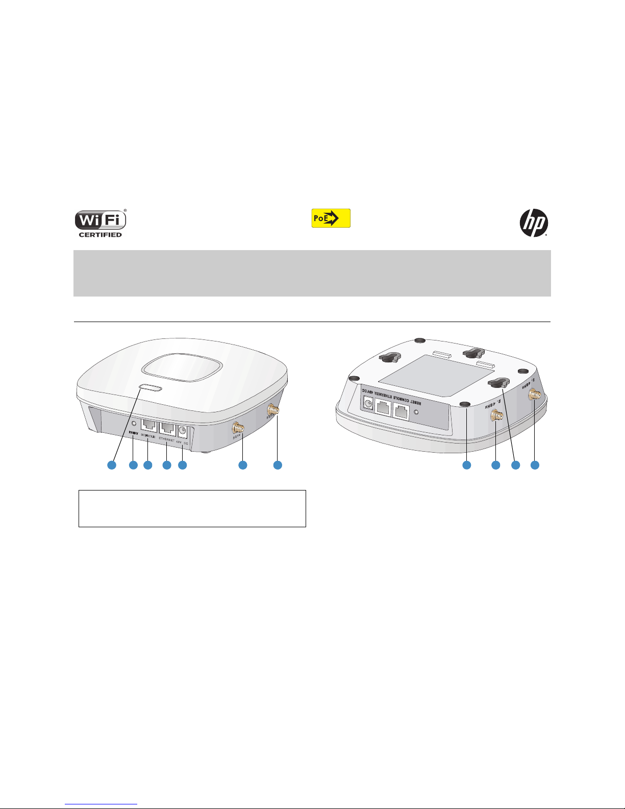
1: Status LED
4: Ethernet port 7: Rubber feet (4)
2: Reset button 5: Power connector 8: 2.4 GHz antenna ports (2)
3: Console port 6: 5 GHz antenna ports (2)
9: Mounting hook holes (3)
25 26262423221
7 28 2829
Page 2

HP 425 Wireless Dual Radio 802.11n Access Point Quickstart 2 Important information to read before installing
Ports
•
Ethernet:
Auto-sensing 10/100/1000 BaseT Ethernet port with RJ-45
connector. The port supports PoE (Power over Ethernet) 802.3af.
•
Console:
Standard console (serial) port with RJ-45 connector.
•
Antenna
: Two 2.4 GHz antenna ports and two 5 GHz antenna ports.
•
Power
: 48V DC.
Caution: Never connect the Console port to an Ethernet switch or
PoE power source. This can damage the AP. Connect it only to other
serial ports using an RJ-45 to Serial Port adapter.
Radios and antennas
The AP features two radios: 802.11n/a on Radio 1 and 802.11n/b/g on Radio 2
with 2x2 MIMO two-spatial-stream 802.11n.
The AP contains four internal dual-band, MIMO antennas. It also provides two
antenna connectors for each radio.
Reset button
The Reset button is located at the bottom of the AP, labeled as 2 on page 1. To
reset the AP, press and quickly release the button. To reset the AP to factory
defaults, press and hold the button for approximately eight seconds until the
LED flashes green three times.
Important information to read before installing
Warn ing: Professional installation is required. For indoor installation
only. Before installing or using the AP, consult with a professional installer
trained in RF installation and knowledgeable in local regulations including
building and wiring codes, safety, channel, power, indoor/outdoor
restrictions, and license requirements for the intended country. The end
user is responsible for ensuring that installation and use comply with local
safety and radio regulations.
Before installing the AP, read all of the safety instructions in the Compliance
and Safety Guide included with the AP.
Cabling: You must use Cat 5e (or a higher category) cables, and where
applicable, surge protection.
Plenum installation: The AP can be installed in a plenum. The AP is suitable
for use in environmental air space in accordance with Section 300-22(C) of the
National Electrical Code, and Sections 2-128, 12-010(3) and 12-100 of the
Canadian Electrical Code, Part 1, CSA C22.1. It should be installed in a similar
orientation as in a ceiling installation. However, a qualified installer can
determine how to install/secure the AP in a plenum in an appropriate and safe
manner. Plenum-rated cables and attachment hardware must be used.
Safety: Consider the following safety information during installation:
•
If your network covers an area served by more than one power distribution
system, ensure that all safety grounds are securely interconnected.
•
Network cables can occasionally be subject to hazardous transient
voltages (caused by lightning or disturbances in the electrical power grid).
•
Handle exposed metal components of the network with caution.
•
The AP is powered on when connected to a PoE power source or a local
power supply.
•
The AP and all interconnected equipment must be installed indoors within
the same building (except for outdoor antennas), including all
PoE-powered network connections, as described by Environment A of the
IEEE 802.3af standard.
•
Install the AP in a dry area, away from liquids.
•
Ensure that the installation site is flat and anti-slip measures are in place.
•
Keep the AP clean and dust-free.
Powering the AP
The AP can be powered by:
•
A 10/100 or 10/100/1000 PoE-enabled switch. Various PoE-enabled
switches are available from HP.
•
A PoE power injector, such as J9407B.
•
An HP 48 volt power adapter, JD055B.
The AP requires 802.3af-compliant PoE. For best performance, HP
recommends that you use a gigabit connection.
Caution:
If the AP will be powered by a user-supplied PoE power injector,
use only a gigabit-compatible power injector. Although 10/100 PoE-enabled
switches are compatible, PoE injectors designed for 10/100 networks only are
not compatible with the AP.
Page 3

HP 425 Wireless Dual Radio 802.11n Access Point Quickstart 3 Selecting the installation site
Selecting the installation site
Consider the following:
•
To meet regulatory RF exposure requirements, install the AP and any
external antennas at least 40 cm (15.75 inches) from any person.
•
Install APs away from RF-emitting electronic devices, such as microwave
ovens.
•
Do not install APs in a location where water seepage or condensation
occurs.
•
Do not place the AP on a metal surface.
•
Install the AP where there are no obstacles and wireless clients can receive
a strong signal from the AP.
Installation
The AP can be mounted on a non-metallic table or shelf, a wall, or a ceiling.
When mounting on a wall or ceiling, mount the AP bracket first, and then
attach the AP to the bracket.
See also the HP 425 Wireless 802.11n Access Points Installation Guide.
Preparing for installation
HP recommends that you connect power and verify the Ethernet cable and
LEDs before you install the AP in a hard-to-reach location.
Record the MAC address and AP serial number for future reference.
If part of the power line is routed outdoors, connect the AP power cord to a
user-supplied power strip with lightning protection.
Placing the AP on a table or shelf
1. Attach the rubber feet to the back of the AP (callout 7 on page 1), and
place the AP back-side down on the table or shelf.
2. Connect an Ethernet cable to the AP.
3. Connect the other end of the Ethernet cable to a PoE-capable device, such
as an Ethernet switch.
Mounting on a wall
1. Hold the mounting bracket with the narrow end facing up, against the wall
where you want to install the AP. Mark the location of the three screw
holes.
2. Drill three holes for the wall anchors, typically 5 mm (3/16 inch) in
diameter.
3. Insert the anchors and tap them flush with the wall surface.
4. Use the mounting screws to attach the mounting bracket to the wall.
Proceed to Attach the AP on page 5.
Mounting on a suspended ceiling
The AP can be mounted on a suspended ceiling using a T-rail holder.
Note: The width of the T-rail must be between 16 mm (0.63 inches) and 28
mm (1.10 inches).
1: Hook 2: Screw hole 3: Clip 4: T-rail hook cut-out
1 2
3
4
Ø5.0
40.0
103.0
86.0
136.0
Page 4

HP 425 Wireless Dual Radio 802.11n Access Point Quickstart 4 Installation
1. Loosen, but do not remove all four M3 screws (7) on the clip holders (3).
2. Slide the T-rail clips away from the T-rail holder until the opening is wider
than the T-rail (arrow 1).
3. Attach the T-rail holder onto the T-rail, slide the T-rail clips toward the
T-rail holder until it closes around the T-rail (arrow 2), and then tighten
the M3 screws.
4. Verify that the T-rail holder is firmly attached to the T-rail.
5.
Hook the mounting bracket clip (3) onto the T-rail holder mounting hook (2).
6. Use the two M4 screws (6) to attach the mounting bracket to the T-rail
holder, and verify that the bracket is firmly anchored to the T-rail.
Proceed to Attach the AP on page 5.
Mounting on a ceiling tile
You can mount the AP on a ceiling tile if the ceiling tile is less that 18 mm
(0.71 inches) and is able to bear a weight of at least 5 kg (11.02 lb).
Caution:
Do not mount the AP on a ceiling that is made of low-strength
material such as plaster. If this installation method is required in such an
environment, you must put a high-strength plate beneath the ceiling to secure
the installation.
1: T-rail clip 4: T-rail holder 7: M3 x 8 screw
2: M4 screw nut 5: M3 screw nut 8: Mounting hook
3: Clip holder 6: M4 x 5 screw
1 2 3
4
5
6
7
8
1 2
1: M4 x 5 screw 2: Mounting hook 3: Mounting clip 4: Hook
4
3
2
1
Page 5

HP 425 Wireless Dual Radio 802.11n Access Point Quickstart 5 Removing the AP
1. Hold the mounting bracket up against the ceiling tile where you want to
install it. Mark the location of the screw holes.
2. Drill three 5.0 mm (3/16 inch) holes in the ceiling tile.
3. Insert the hex-head bolts into the mounting bracket screw holes and
through the holes in the ceiling tile.
4. Fasten the washers and hex nuts to the hex-head bolts on the other side
of the ceiling tile.
Attach the AP
1. Connect the Ethernet cable to the AP.
2. Hold the bottom of the AP against the AP bracket, aligning the AP
mounting hook holes with the hooks on the AP bracket.
3. While firmly holding the AP against the AP bracket, slide the AP toward
the wide end of the bracket until the AP snaps onto the bracket. Do not let
go of the AP until you confirm that it is firmly in place.
4. Connect the Ethernet cable to a PoE-capable device, such as an Ethernet
switch.
Removing the AP
To remove the AP from the bracket, insert a straight-edge screwdriver on
either side of the AP (in line with either the 2.4 GHz-2 or 5 GHz-2 antenna
ports) between the bracket and the clip. Rotate the screwdriver slightly so that
the clip flexes away from the bracket, and then slide the AP toward the narrow
end of the mounting bracket until the AP is released. Be sure to firmly grip the
AP so that it does not fall.
Controllers
To become operational, the AP must establish a management tunnel with an
HP 10500/7500 WLAN Module, HP 830, HP WX5002/WX5004, or HP
MSM720/MSM760/MSM765 zl Controller. The controller manages the AP and
provides all configuration settings.
Note: Both controller families cannot coexist on the same network. HP
10500/7500 WLAN Module, HP 830, and HP WX5002/WX5004
Controllers are not compatible with HP MSM7xx Controllers.
When power is applied, the AP establishes a connection to the controller
automatically if the AP and the controller are on the same subnet and have IP
connectivity.
For more information about using the AP with HP 10500/7500 WLAN Module,
HP 830, or WX5002/WX5004 Controllers, see the HP 830 Switch and HP
10500/7500 20G Module Access Controller Module Basic Configuration Guide,
or the H3C WX Series Access Controller Module Configuration Guide.
For more information about using the AP with MSM7xx Controllers, see
Working with controlled APs in the MSM7xx Controllers Configuration Guide.
1
2
Page 6

HP 425 Wireless Dual Radio 802.11n Access Point Quickstart 6 AP status LEDs
© Copyright 2013 Hewlett-Packard Development
Company, L.P. The information contained herein is
subject to change without notice.
September 2013
Printed in
Document part # 5998-4326
*5998-4326*
AP status LEDs
HP 425 optional antennas
Only the following antenna is approved for use with the AP:
Caution:
For external antennas only: Depending on the country of use and
your radio settings, it may be mandatory to reduce the radio transmission
power level to maintain regulatory compliance. For specific power limits for
your country, see the HP 425 AP Antenna Power-Level Setting Guide available
from www.hp.com/support/manuals. Search by antenna part number.
For important safety, environmental, and regulatory information, see also
Safety and Compliance Information for Server, Storage, Power, Networking,
and Rack Products, available at:
www.hp.com/support/Safety-Compliance-EnterpriseProducts
LED color State Description
Green
Flashing
1 flash/sec.
The AP is booting.
Fading in/out
At least one client is connected to the 2.4
GHz radio.
Blue
Flashing
2 flashes/sec.
The AP is updating its system software
image.
Flashing
2 sec. on/
2 sec. off
The AP is booted and is registered to the
controller. There is no client connected.
Fading in/out
At least one client is connected to the 5 GHz
radio.
Orange
On for more
than 20 sec.
An initialization exception has occurred.
Flashing
1 flash/sec.
There is a problem with the radio module.
Flashing
2 flashes/sec.
Both radios are disabled or the Ethernet port
is disabled while no local mesh peer exists.
Green/Blue
Alternately
fading green
and blue
Clients are connected to both the 2.4 GHz
and 5 GHz radios.
Part Typ e Band Gain Use Elements
JG696A Omni-directional 2.4/5GHz 2.5/6dBi Indoor 4
 Loading...