

Page 1

HP EVA 4000/6000/8000 and EVA 4100/6100/8100 User Guide
Abstract
This document is intended for customers who operate and manage the EVA 4000/6000/8000 and EVA 4100/6100/8100
storage systems. These models are sometimes referred to as EVA4x00, EVA6x00, and EVA8x00 or as EVAx000 and x100.
IMPORTANT: With the release of the P6300/P6500 EVA, the EVA family name has been rebranded to HP P6000 EVA. The
names for all existing EVA array models will not change. The rebranding also affects related EVA software. The following
product names have been rebranded:
• HP P6000 Command View (formerly HP StorageWorks Command View EVA)
• HP P6000 Business Copy (formerly HP StorageWorks Business Copy EVA)
• HP P6000 Continuous Access (formerly HP StorageWorks Continuous Access EVA)
• HP P6000 Performance Data Collector (formerly EVAPerf)
HP Part Number: 5697-1119
Published: January 2012
Edition: 12
Page 2

© Copyright 2005, 2012 Hewlett-Packard Development Company, L.P.
The information contained herein is subject to change without notice. The only warranties for HP products and services are set forth in the express
warranty statements accompanying such products and services. Nothing herein should be construed as constituting an additional warranty. HP shall
not be liable for technical or editorial errors or omissions contained herein.
Warranty
To obtain a copy of the warranty for this product, see the warranty information website:
http://www.hp.com/go/storagewarranty
Acknowledgements
Microsoft® and Windows® are U.S. registered trademarks of Microsoft Corporation.
UNIX® is a registered trademark of The Open Group.
Page 3

Contents
1 Enterprise Virtual Array startup...................................................................11
EVA8000/8100 storage system connections..............................................................................11
EVA6000/6100 storage system connections...............................................................................12
EVA4000/4100 storage system connections..............................................................................12
Direct connect........................................................................................................................13
iSCSI connection configurations................................................................................................14
Fabric connect iSCSI..........................................................................................................14
Direct connect iSCSI...........................................................................................................14
Procedures for getting started...................................................................................................15
Gathering information........................................................................................................15
Host information...........................................................................................................15
Setting up a controller pair using the OCP............................................................................15
Entering the WWN.......................................................................................................16
Entering the WWN checksum.........................................................................................17
Entering the storage system password..............................................................................17
Installing HP P6000 Command View....................................................................................17
Installing optional EVA software licenses...............................................................................18
2 Enterprise Virtual Array hardware components.............................................19
Physical layout of the storage system.........................................................................................19
Fibre Channel drive enclosures.................................................................................................20
Enclosure layout.................................................................................................................20
I/O modules.....................................................................................................................21
I/O module status indicators..........................................................................................22
Fiber Optic Fibre Channel cables.........................................................................................23
Copper Fibre Channel cables..............................................................................................23
Fibre Channel disk drives....................................................................................................23
Disk drive status indicators..............................................................................................24
Disk drive status displays................................................................................................24
Disk drive blank............................................................................................................25
Power supplies and blowers................................................................................................25
Power supplies..............................................................................................................25
Blowers........................................................................................................................26
Drive enclosure EMU..........................................................................................................26
Controls and displays....................................................................................................27
EMU functions..............................................................................................................27
EMU monitoring functions..............................................................................................28
EMU displays...............................................................................................................28
EMU indicator displays..................................................................................................29
Using the alphanumeric display......................................................................................29
Alphanumeric display description...............................................................................29
Display groups.........................................................................................................29
EMU pushbutton status indicators....................................................................................30
Audible alarm operations ..............................................................................................30
Audible alarm patterns..............................................................................................30
Controlling the audible alarm.....................................................................................31
Enabling the audible alarm............................................................................................31
Muting or unmuting the audible alarm.............................................................................31
Disabling the audible alarm...........................................................................................32
Enclosure number feature...............................................................................................32
En description..........................................................................................................32
Enclosure address bus...............................................................................................33
Contents 3
Page 4

Enclosure address bus connections..............................................................................34
Error Condition Reporting...............................................................................................34
Error condition categories..........................................................................................35
Error queue.............................................................................................................35
Error condition report format......................................................................................36
Navigating the error condition display........................................................................36
Reporting group feature.................................................................................................37
Reporting group numbers..........................................................................................37
Fibre Channel loop switches.....................................................................................................38
30-10022-01 loop switch.....................................................................................................38
Power-on self test (POST).................................................................................................39
30-10010-02 loop switch....................................................................................................39
Power-on self test (POST).................................................................................................40
Reading the switch status indicators.................................................................................40
Problem isolation..........................................................................................................41
HSV controllers.......................................................................................................................41
High availability features....................................................................................................43
Operator control panel.......................................................................................................43
Status indicators............................................................................................................44
Navigation buttons........................................................................................................45
Alphanumeric display....................................................................................................45
Displaying the OCP menu tree........................................................................................45
Displaying system information.........................................................................................47
Displaying versions system information.............................................................................47
Shutting down the system...............................................................................................47
Shutting the controller down...........................................................................................48
Restarting the system......................................................................................................48
Uninitializing the system.................................................................................................48
Password options..........................................................................................................49
Changing a password...................................................................................................49
Clearing a password.....................................................................................................49
Power supplies...................................................................................................................50
Blowers............................................................................................................................50
Cache battery...................................................................................................................51
HSV controller cabling........................................................................................................51
Racks....................................................................................................................................52
Rack configurations............................................................................................................52
Power distribution...............................................................................................................52
PDUs...........................................................................................................................54
PDU 1.....................................................................................................................54
PDU 2.....................................................................................................................54
PDMs..........................................................................................................................54
Rack AC power distribution............................................................................................55
Rack System/E power distribution components..................................................................56
Rack AC power distribution........................................................................................56
Moving and stabilizing a rack.............................................................................................56
3 Enterprise Virtual Array operation...............................................................59
Best practices.........................................................................................................................59
Operating tips and information................................................................................................59
Reserving adequate free space............................................................................................59
Using FATA disk drives........................................................................................................59
Changing the host port topology..........................................................................................59
Host port connection limit on B-series 3200 and 3800 switches...............................................59
Enabling Boot from SAN for Windows direct connect.............................................................60
4 Contents
Page 5

Windows 2003 MSCS cluster installation..............................................................................60
Connecting to C-series switches...........................................................................................60
HP Insight Remote Support software.....................................................................................60
Failback preference setting for HSV controllers............................................................................62
Changing virtual disk failover/failback setting.......................................................................64
Storage system shutdown and startup........................................................................................64
Shutting down the storage system.........................................................................................64
Starting the storage system..................................................................................................65
Saving storage system configuration data...................................................................................65
Adding disk drives to the storage system....................................................................................67
Creating disk groups..........................................................................................................68
Adding a disk drive...........................................................................................................69
Removing the drive blank...............................................................................................69
Changing the Device Addition Policy...............................................................................69
Installing the disk drive...................................................................................................69
Checking status indicators..............................................................................................70
Adding the disk to a disk group......................................................................................71
Handling fiber optic cables......................................................................................................71
4 Configuring application servers..................................................................72
Overview..............................................................................................................................72
Clustering..............................................................................................................................72
Multipathing..........................................................................................................................72
Installing Fibre Channel adapters..............................................................................................72
Testing connections to the EVA.................................................................................................73
Adding hosts..........................................................................................................................73
Creating and presenting virtual disks.........................................................................................73
Verifying virtual disk access from the host...................................................................................74
Configuring virtual disks from the host.......................................................................................74
HP-UX...................................................................................................................................74
Scanning the bus...............................................................................................................74
Creating volume groups on a virtual disk using vgcreate.........................................................75
IBM AIX................................................................................................................................75
Accessing IBM AIX utilities..................................................................................................75
Adding hosts.....................................................................................................................76
Creating and presenting virtual disks....................................................................................76
Verifying virtual disks from the host.......................................................................................76
Linux.....................................................................................................................................77
Driver failover mode...........................................................................................................77
Installing a Qlogic driver....................................................................................................77
Upgrading Linux components..............................................................................................78
Upgrading qla2x00 RPMs..............................................................................................78
Detecting third-party storage...........................................................................................78
Compiling the driver for multiple kernels...........................................................................79
Uninstalling the Linux components........................................................................................79
Using the source RPM.........................................................................................................79
Verifying virtual disks from the host.......................................................................................80
OpenVMS.............................................................................................................................80
Updating the AlphaServer console code, Integrity Server console code, and Fibre Channel FCA
firmware...........................................................................................................................80
Verifying the Fibre Channel adapter software installation........................................................80
Console LUN ID and OS unit ID...........................................................................................80
Adding OpenVMS hosts.....................................................................................................81
Scanning the bus...............................................................................................................81
Configuring virtual disks from the OpenVMS host...................................................................82
Contents 5
Page 6

Setting preferred paths.......................................................................................................83
Oracle Solaris........................................................................................................................83
Loading the operating system and software...........................................................................83
Configuring FCAs with the Oracle SAN driver stack...............................................................83
Configuring Emulex FCAs with the lpfc driver....................................................................84
Configuring QLogic FCAs with the qla2300 driver.............................................................85
Fabric setup and zoning.....................................................................................................87
Oracle StorEdge Traffic Manager (MPxIO)/Sun Storage Multipathing.......................................87
Configuring with Veritas Volume Manager............................................................................87
Configuring virtual disks from the host...................................................................................89
Verifying virtual disks from the host..................................................................................90
Labeling and partitioning the devices...............................................................................91
VMware................................................................................................................................92
Installing or upgrading VMware .........................................................................................92
Configuring the EVA with VMware host servers......................................................................92
Configuring an ESX server ..................................................................................................93
Loading the FCA NVRAM..............................................................................................93
Setting the multipathing policy........................................................................................93
Specifying DiskMaxLUN.................................................................................................94
Verifying connectivity.....................................................................................................94
Verifying virtual disks from the host.......................................................................................95
5 Customer replaceable units........................................................................96
Customer self repair (CSR).......................................................................................................96
Parts only warranty service..................................................................................................96
Best practices for replacing hardware components......................................................................96
Component replacement videos...........................................................................................96
Verifying component failure.................................................................................................96
Procuring the spare part......................................................................................................96
Replaceable parts.........................................................................................................97
Replacing the failed component...........................................................................................99
Returning the defective part...............................................................................................100
6 Support and other resources....................................................................101
Contacting HP......................................................................................................................101
Subscription service..............................................................................................................101
Documentation feedback.......................................................................................................101
Related information...............................................................................................................101
Documents......................................................................................................................101
Websites........................................................................................................................101
Document conventions and symbols........................................................................................102
Rack stability........................................................................................................................102
Customer self repair..............................................................................................................103
A Regulatory notices and specifications........................................................104
Regulatory notices................................................................................................................104
Federal Communications Commission (FCC) notice...............................................................104
FCC Class A certification.............................................................................................104
Class A equipment......................................................................................................104
Class B equipment......................................................................................................104
Declaration of conformity for products marked with the FCC logo, United States only...........105
Modifications.............................................................................................................105
Cables.......................................................................................................................105
Laser device....................................................................................................................105
Laser safety warnings..................................................................................................105
Compliance with CDRH regulations...............................................................................105
6 Contents
Page 7

Certification and classification information..........................................................................106
Canadien notice (avis Canadien).......................................................................................106
Class A equipment......................................................................................................106
Class B equipment......................................................................................................106
European union notice......................................................................................................106
Notice for France.............................................................................................................106
WEEE Recycling Notices...................................................................................................106
English notice.............................................................................................................106
Dutch notice...............................................................................................................107
Czechoslovakian notice...............................................................................................107
Estonian notice...........................................................................................................107
Finnish notice.............................................................................................................107
French notice..............................................................................................................108
German notice............................................................................................................108
Greek notice..............................................................................................................108
Hungarian notice .......................................................................................................109
Italian notice..............................................................................................................109
Latvian notice.............................................................................................................109
Lithuanian notice.........................................................................................................109
Polish notice...............................................................................................................109
Portuguese notice........................................................................................................110
Slovakian notice.........................................................................................................110
Slovenian notice.........................................................................................................110
Spanish notice............................................................................................................110
Swedish notice............................................................................................................111
Germany noise declaration...............................................................................................111
Japanese notice...............................................................................................................111
Harmonics conformance (Japan)...................................................................................111
Taiwanese notice.............................................................................................................111
Japanese power cord notice..............................................................................................111
Country-specific certifications.............................................................................................112
Storage system specifications..................................................................................................112
Physical specifications......................................................................................................112
Environmental specifications..............................................................................................112
Power specifications.........................................................................................................113
B EMU-generated condition reports..............................................................117
Condition report format.........................................................................................................117
Correcting errors..................................................................................................................117
Drive conditions...............................................................................................................118
0.1.en.01 CRITICAL condition—Drive configuration or drive link rate...................................118
0.1.en.02 INFORMATION condition—Drive missing.........................................................119
0.1.en.03 INFORMATION condition—Drive software lock active........................................119
0.1.en.04 CRITICAL condition—Loop a drive link rate incorrect..........................................119
0.1.en.05 CRITICAL condition—Loop b drive link rate incorrect..........................................120
Power supply conditions....................................................................................................120
0.2.en.01 NONCRITICAL Condition—Power supply AC input missing................................120
0.2.en.02 UNRECOVERABLE condition—Power supply missing ........................................121
0.2.en.03 CRITICAL condition—Power supply load unbalanced .......................................121
Blower conditions............................................................................................................121
0.3.en.01 NONCRITICAL condition—Blower speed.........................................................122
0.3.en.02 CRITICAL condition—Blower speed.................................................................122
0.3.en.03 UNRECOVERABLE condition—Blower failure ..................................................122
0.3.en.04 UNRECOVERABLE condition—Blower internal..................................................122
0.3.en.05 NONCRITICAL condition—Blower missing......................................................122
Contents 7
Page 8

0.3.en.06 UNRECOVERABLE condition—No blowers installed .........................................123
Temperature conditions.....................................................................................................123
0.4.en.01 NONCRITICAL condition—High temperature...................................................123
0.4.en.02 CRITICAL condition—High temperature...........................................................124
0.4.en.03 NONCRITICAL condition—Low temperature....................................................124
0.4.en.04 CRITICAL condition—Low temperature............................................................124
0.4.en.05 UNRECOVERABLE condition—High temperature .............................................124
EMU conditions...............................................................................................................125
Resetting the EMU.......................................................................................................125
07.01.01 CRITICAL condition—EMU internal clock...........................................................125
07.01.02 UNRECOVERABLE condition—EMU interrupted ................................................125
0.7.01.03 UNRECOVERABLE Condition—Power supply shutdown .....................................126
0.7.01.04 INFORMATION condition—EMU internal data.................................................126
0.7.01.05 UNRECOVERABLE condition—Backplane NVRAM ...........................................126
0.7.01.10 NONCRITICAL condition—NVRAM invalid read data .......................................126
0.7.01.11 NONCRITICAL condition—EMU NVRAM write failure .......................................126
0.7.01.12 NONCRITICAL condition—EMU cannot read NVRAM data ...............................127
0.7.01.13 UNRECOVERABLE condition—EMU load failure ...............................................127
0.7.01.14 NONCRITICAL condition—EMU enclosure address ...........................................127
0.7.01.15 UNRECOVERABLE condition—EMU hardware failure ........................................127
0.7.01.16 INFORMATION condition—EMU internal ESI data corrupted ..............................127
0.7.01.17 UNRECOVERABLE condition—Power shutdown failure........................................128
0.7.01.18 UNRECOVERABLE condition—EMU hardware failure.........................................128
0.7.01.19 UNRECOVERABLE condition—EMU ESI driver failure.........................................128
Transceiver conditions.......................................................................................................128
0.F.en.01 CRITICAL condition—Transceiver incompatibility ...............................................129
0.F.en.02 CRITICAL condition—Transceiver data signal lost ..............................................129
0.F.en.03 CRITICAL condition—Transceiver fibre channel drive enclosure bus fault...............129
0.F.en.04 CRITICAL condition—Transceiver removed........................................................129
0.F.en.05 CRITICAL condition—Invalid fibre channel character..........................................130
CAN bus communication port conditions............................................................................130
Resetting the EMU.......................................................................................................130
1.1.03.01 NONCRITICAL condition—Communication error...............................................130
1.1.03.02 INFORMATION condition—Recovery completed...............................................130
1.1.03.03 INFORMATION condition—Overrun recovery...................................................131
Voltage sensor and current sensor conditions.......................................................................131
1.2.en.01 NONCRITICAL condition—High voltage .........................................................131
1.2.en.02 CRITICAL condition—High voltage .................................................................131
1.2.en.03 NONCRITICAL condition—Low voltage ..........................................................131
1.2.en.04 CRITICAL condition—Low voltage ..................................................................132
1.3.en.01 NONCRITICAL condition—High current ..........................................................132
1.3.en.02 CRITICAL condition—High current ..................................................................132
Backplane conditions.......................................................................................................132
8.2.01.10 NONCRITICAL condition—Backplane NVRAM read .........................................132
8.2.01.11 NONCRITICAL condition—Backplane NVRAM write failure ...............................132
8.2.01.12 NONCRITICAL condition—Backplane NVRAM read failure ...............................132
8.2.01.13 NONCRITICAL condition—Backplane WWN is blank.......................................132
I/O Module conditions.....................................................................................................133
8.7.en.01 CRITICAL condition—I/O module unsupported ................................................133
8.7.en.02 CRITICAL condition—I/O module communication ............................................133
8.7.en.10 NONCRITICAL condition—I/O module NVRAM read ......................................133
8.7.en.11 NONCRITICAL condition—I/O module NVRAM write........................................133
8.7.en.12 NONCRITICAL condition—I/O Module NVRAM read failure .............................134
8.7.en.13 NONCRITICAL condition—I/O module removed...............................................134
Host conditions................................................................................................................134
8 Contents
Page 9

C Controller fault management....................................................................135
Using HP P6000 Command View ..........................................................................................135
GUI termination event display................................................................................................135
GUI event display............................................................................................................135
Fault management displays...............................................................................................136
Displaying Last Fault Information...................................................................................136
Displaying Detailed Information....................................................................................136
Interpreting fault management information......................................................................137
D Non-standard rack specifications..............................................................138
Rack specifications................................................................................................................138
Internal component envelope.............................................................................................138
EIA310-D standards..........................................................................................................138
EVA cabinet measures and tolerances.................................................................................138
Weights, dimensions and component CG measurements.......................................................138
Airflow and Recirculation..................................................................................................139
Component Airflow Requirements..................................................................................139
Rack Airflow Requirements...........................................................................................139
Configuration Standards...................................................................................................139
Environmental and operating specifications..............................................................................139
Power requirements..........................................................................................................140
UPS Selection.............................................................................................................141
Environmental specifications..............................................................................................143
Shock and vibration specifications......................................................................................144
E Single Path Implementation......................................................................145
High-level solution overview...................................................................................................145
Benefits at a glance..............................................................................................................145
Installation requirements........................................................................................................146
Recommended mitigations.....................................................................................................146
Supported configurations.......................................................................................................146
General configuration components.....................................................................................146
Connecting a single path HBA server to a switch in a fabric zone..........................................146
HP-UX configuration.........................................................................................................148
Requirements..............................................................................................................148
HBA configuration.......................................................................................................148
Risks..........................................................................................................................148
Limitations..................................................................................................................148
Windows Server (32-bit) configuration................................................................................149
Requirements..............................................................................................................149
HBA configuration.......................................................................................................149
Risks..........................................................................................................................149
Limitations..................................................................................................................149
Windows Server (64-bit) configuration................................................................................150
Requirements..............................................................................................................150
HBA configuration.......................................................................................................150
Risks..........................................................................................................................150
Limitations..................................................................................................................150
Oracle Solaris configuration..............................................................................................151
Requirements..............................................................................................................151
HBA configuration.......................................................................................................151
Risks..........................................................................................................................151
Limitations..................................................................................................................152
Tru64 UNIX configuration.................................................................................................152
Requirements..............................................................................................................152
HBA configuration.......................................................................................................152
Contents 9
Page 10

Risks..........................................................................................................................152
OpenVMS configuration...................................................................................................153
Requirements..............................................................................................................153
HBA configuration.......................................................................................................153
Risks..........................................................................................................................153
Limitations..................................................................................................................154
Linux (32-bit) configuration................................................................................................154
Requirements..............................................................................................................154
HBA configuration.......................................................................................................154
Risks..........................................................................................................................154
Limitations..................................................................................................................155
Linux (64-bit) configuration................................................................................................155
Requirements..............................................................................................................155
HBA configuration.......................................................................................................155
Risks..........................................................................................................................155
Limitations..................................................................................................................156
IBM AIX configuration......................................................................................................156
Requirements..............................................................................................................156
HBA configuration.......................................................................................................156
Risks..........................................................................................................................157
Limitations..................................................................................................................157
VMware configuration......................................................................................................157
Requirements..............................................................................................................157
HBA configuration.......................................................................................................157
Risks..........................................................................................................................158
Limitations..................................................................................................................158
Failure scenarios...................................................................................................................158
HP-UX.............................................................................................................................158
Windows Server..............................................................................................................159
Oracle Solaris.................................................................................................................159
OpenVMS and Tru64 UNIX..............................................................................................160
Linux..............................................................................................................................160
IBM AIX..........................................................................................................................161
VMware.........................................................................................................................161
Glossary..................................................................................................163
Index.......................................................................................................175
10 Contents
Page 11
1 Enterprise Virtual Array startup
This chapter describes the procedures to install and configure the Enterprise Virtual Array. When
these procedures are complete, you can begin using your storage system.
NOTE: Installation of the Enterprise Virtual Array should be done only by an HP authorized
service representative. The information in this chapter provides an overview of the steps involved
in the installation and configuration of the storage system.
This chapter consists of:
EVA8000/8100 storage system connections
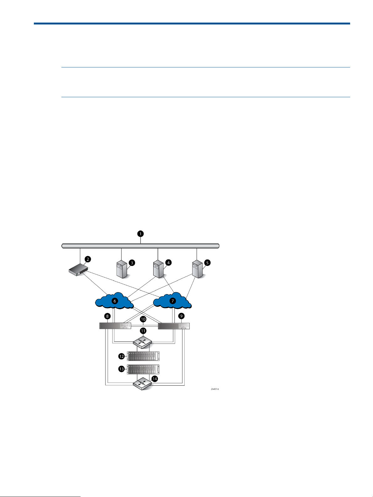
Figure 1 (page 11) shows how the storage system is connected to other components of the storage
solution.
• The HSV210-A and HSV210-B controllers connect via four host ports (FP1, FP2, FP3, and FP4)
to the Fibre Channel fabrics. The hosts that will access the storage system are connected to
the same fabrics.
• The HP P6000 Command View management server also connects to the fabric.
• The controllers connect through two loop pairs to the drive enclosures. Each loop pair consists
of two independent loops, each capable of managing all the disks should one loop fail. Four
FC loop switches are used to connect the controllers to the disk enclosures.
Figure 1 EVA8000/8100 configuration
8 Controller A1 Network interconnection
9 Controller B2 Management server
10 Cache mirror ports3 Non-host
11 FC loop switch4 Host X
12 Drive enclosure 15 Host Z
13 Drive enclosure 26 Fabric 1
14 FC loop switch7 Fabric 2
EVA8000/8100 storage system connections 11
Page 12
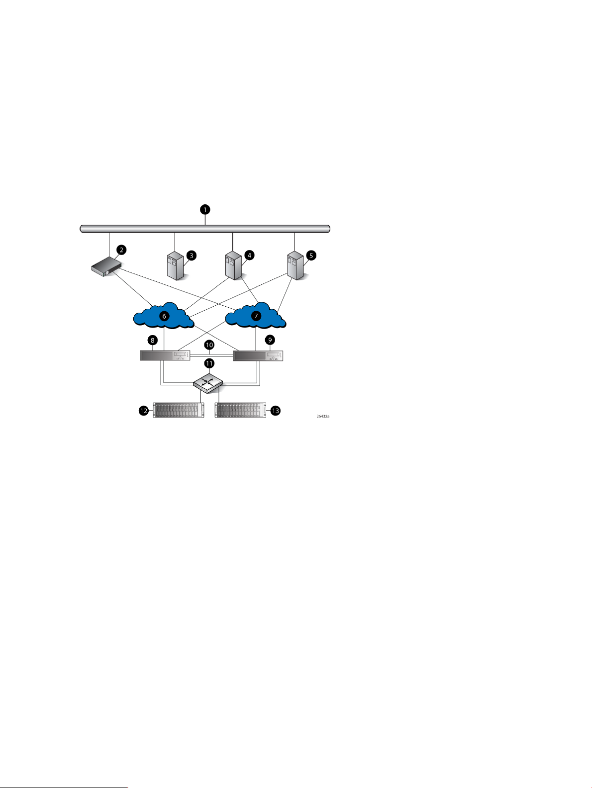
EVA6000/6100 storage system connections
Figure 2 (page 12) shows a typical EVA6000/6100 SAN topology:
• The HSV200-A and HSV200-B controllers connect via two host ports (FP1 and FP2) to the
Fibre Channel fabrics. The hosts that will access the storage system are connected to the same
fabrics.
• The HP Command View EVA management server also connects to both fabrics.
• The controllers connect through one loop pair to the drive enclosures. The loop pair consists
of two independent loops, each capable of managing all the disks should one loop fail. Two
FC loop switches are used to connect the controllers to the disk enclosures.
Figure 2 EVA6000/6100 configuration
8 Controller A1 Network interconnection
9 Controller B2 Management server
10 Cache mirror ports3 Non-host
11 FC loop switch4 Host X
12 Drive enclosure 15 Host Z
13 Drive enclosure 26 Fabric 1
7 Fabric 2
EVA4000/4100 storage system connections
Figure 3 (page 13) shows a typical EVA 4000/4100 SAN topology:
• The HSV200-A and HSV200-B controllers connect via two host ports (FP1 and FP2) to the
Fibre Channel fabrics. The hosts that will access the storage system are connected to the same
fabrics.
• The HP P6000 Command View management server also connects to both fabrics.
• The controllers connect through one loop pair to the drive enclosures. The loop pair consists
of two independent loops, each capable of managing all the disks should one loop fail. The
controllers connect directly to the disk enclosures.
12 Enterprise Virtual Array startup
Page 13
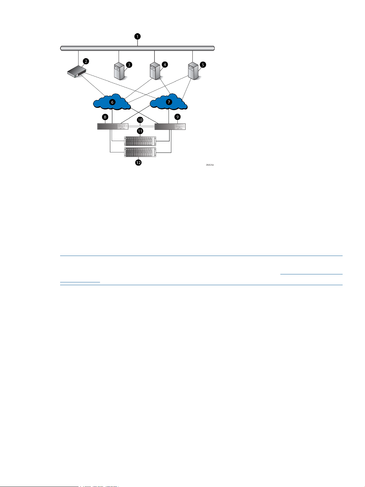
Figure 3 EVA4000/4100 configuration
7 Fabric 21 Network interconnection
8 Controller A2 Management server
9 Controller B3 Non-host
10 Cache mirror ports4 Host X
11 Drive enclosure 15 Host Z
12 Drive enclosure 26 Fabric 1
Direct connect
NOTE: Direct connect is currently supported on Microsoft Windows only. For more information
on direct connect, go the Single Point of Connectivity Knowledge (SPOCK) at: http://www.hp.com/
storage spock.
Direct connect provides a lower cost solution for smaller configurations. When using direct connect,
the storage system controllers are connected directly to the host(s), not to SAN Fibre Channel
switches. Make sure the following requirements are met when configuring your environment for
direct connect:
• A management server running HP P6000 Command View must be connected to one port on
each EVA controller. The management host must use dual HBAs for redundancy.
• To provide redundancy, it is recommended that dual HBAs be used for each additional host
connected to the storage system. Using this configuration, up to four hosts (including the
management host) can be connected to an EVA8x00, and up to two hosts can be connected
to an EVA6x00 or EVA4x00.
• The Host Port Configuration must be set to Direct Connect using the OCP.
• HP P6000 Continuous Access cannot be used with direct connect configurations.
• The HSV controller firmware cannot differentiate between an empty host port and a failed
host port in a direct connect configuration. As a result, the Connection state dialog box on
the Controller Properties window displays Connection failed for an empty host port. To fix this
problem, insert an optical loop-back connector into the empty host port; the Connection state
will display Connected. For more information about optical loop-back connectors, contact
your HP-authorized service provider.
Direct connect 13
Page 14

iSCSI connection configurations
The EVA4x00/6x00/8x00 support iSCSI attach configurations using the HP MPX100. Both fabric
connect and direct connect are supported for iSCSI configurations. For complete information on
iSCSI configurations, go to the following website:
http://h18006.www1.hp.com/products/storageworks/evaiscsiconnect/index.html
NOTE: An iSCSI connection configuration supports mixed direct connect and fabric connect.
Fabric connect iSCSI
Fabric connect provides an iSCSI solution for EVA Fibre Channel configurations that want to
continue to use all EVA ports on FC or if the EVA is also used for HP P6000 Continuous Access.
Make sure the following requirements are met when configuring your MPX100 environment for
fabric connect:
• A maximum of two MPX100s per storage system are supported
• Each storage system port can connect to a maximum of two MPX100 FC ports.
• Each MPX100 FC port can connect to a maximum of one storage system port.
• In a single MPX100 configuration, if both MPX100 FC ports are used, each port must be
connected to one storage system controller.
• In a dual MPX100 configuration, at least one FC port from each MPX100 must be connected
to one storage system controller.
• The Host Port Configuration must be set to Fabric Connect using the OCP.
• HP P6000 Continuous Access is supported on the same storage system connected in MPX100
fabric connect configurations.
Direct connect iSCSI
Direct connect provides a lower cost solution for configurations that want to dedicate controller
ports to iSCSI I/O. When using direct connect, the storage system controllers are connected directly
to the MPX100(s), not to SAN Fibre Channel switches.
Make sure the following requirements are met when configuring your MPX100 environment for
direct connect:
• A maximum two MPX100s per storage system are supported.
• In a single MPX100 configuration, if both MPX100 FC ports are used each port must be
connected to one storage system controller.
• In a dual MPX100 configuration, at least one FC port from each MPX100 must be connected
to one storage system controller.
• The Host Port Configuration must be set to Direct Connect using the OCP.
• HP P6000 Continuous Access cannot be used with direct connect configurations.
• EVAs cannot be directly connected to each other to create an HP P6000 Continuous Access
configuration. However, hosts can be directly connected to the EVA in an HP P6000 Continuous
Access configuration. At least one port from each array in an HP P6000 Continuous Access
configuration must be connected to a Fabric connection for remote array connectivity.
14 Enterprise Virtual Array startup
Page 15

Procedures for getting started
documentation.
hardware configuration information.
View.
storage system software documentation for each host's
operating system.
Gathering information
The following items should be available when installing and configuring an Enterprise Virtual Array.
They provide information necessary to set up the storage system successfully.
ResponsibilityStep
Customer1. Gather information and identify all related storage
Customer2. Contact an authorized service representative for
HP Service Engineer3. Enter the World Wide Name (WWN) into the OCP.
HP Service Engineer4. Configure HP P6000 Command View.
Customer5. Prepare the hosts.
HP Service Engineer6. Configure the system through HP P6000 Command
HP Service Engineer7. Make virtual disks available to their hosts. See the
• HP 4x00/6x00/8x00 Enterprise Virtual Array World Wide Name label, which is shipped
with the system
• HP EVA 4000/6000/8000 and EVA 4100/6100/8100 Read Me First
• HP EVA 4000/6000/8000 and EVA 4100/6100/8100 Release Notes (XCS 6.250)
• The latest HP P6000 Command View software (Check the HP P6000 Enterprise Virtual Array
Compatibility Reference for controller software and HP P6000 Command View compatibility.)
Locate these items and keep them handy. You will need them for the procedures in this manual.
Host information
Make a list of information for each host computer that will be accessing the storage system. You
will need the following information for each host:
• The LAN name of the host
• A list of World Wide Names of the FC adapters, also called host bus adapters, through which
the host will connect to the fabric that provides access to the storage system, or to the storage
system directly if using direct connect.
• Operating system type
• Available LUN numbers
Setting up a controller pair using the OCP
NOTE: This procedure should be performed by an HP authorized service representative.
Two pieces of data must be entered during initial setup using the controller OCP:
• World Wide Name (WWN) — Required to complete setup. This procedure should be
performed by an HP authorized service representative.
• Storage system password — Optional. A password provides security allowing only specific
instances of HP P6000 Command View to access the storage system.
Procedures for getting started 15
Page 16
The OCP on either controller can be used to input the WWN and password data. For more
information about the OCP, see “Operator control panel” (page 43).
Table 1 (page 16) lists the push-button functions when entering the WWN, WWN checksum, and
password data.
Table 1 Push button functions
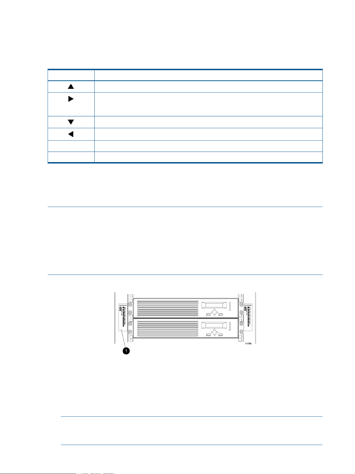
Entering the WWN
Fibre Channel protocol requires that each controller pair have a unique WWN. This 16-character
alphanumeric name identifies the controller pair on the storage system. Two WWN labels attached
to the rack identify the storage system WWN and checksum. See Figure 4 (page 16).
FunctionButton
Selects a character by scrolling up through the character list one character at a time.
Moves forward one character. If you accept an incorrect character, you can move through all 16
characters, one character at a time, until you display the incorrect character. You can then change
the character.
Selects a character by scrolling down through the character list one character at a time.
Moves backward one character.
Returns to the default display.ESC
Accepts all the characters entered.ENTER
NOTE:
• The WWN is unique to a controller pair and cannot be used for any other controller pair or
device anywhere on the network.
• This is the only WWN applicable to any controller installed in a specific physical location,
even a replacement controller.
• Once a WWN is assigned to a controller, you cannot change the WWN while the controller
is part of the same storage system.
Figure 4 Location of the World Wide Name labels
1. World Wide Name labels
Complete the following procedure to assign the WWN to each pair of controllers.
1. Turn the power switches on both controllers off.
2. Apply power to the rack.
3. Turn the power switch on both controllers on.
NOTE: Notifications of the startup test steps that have been executed are displayed while
the controller is booting. It may take up to two minutes for the steps to display. The default
WWN entry display has a 0 in each of the 16 positions.
16 Enterprise Virtual Array startup
Page 17

4. Press or until the first character of the WWN is displayed. Press to accept this character
and select the next.
5. Repeat Step 4 to enter the remaining characters.
6. Press Enter to accept the WWN and select the checksum entry mode.
Entering the WWN checksum
The second part of the WWN entry procedure is to enter the two-character checksum, as follows.
1. Verify that the initial WWN checksum displays 0 in both positions.
2. Press or until the first checksum character is displayed. Press to accept this character
and select the second character.
3. Press or until the second character is displayed. Press Enter to accept the checksum and
exit.
4. Verify that the default display is automatically selected. This indicates that the checksum is
valid.
NOTE: If you enter an incorrect WWN or checksum, the system will reject the data and you must
repeat the procedure.
Entering the storage system password
The storage system password feature enables you to restrict management access to the storage
system. The password must meet the following requirements:
• 8 to 16 characters in length
• Can include upper or lower case letters
• Can include numbers 0 - 9
• Can include the following characters: ! “ # $ % & ‘ ( ) * + , - . / : ; < = > ? @ [ ] ^ _ ` {
| }
• Cannot include the following characters: space ~ \
NOTE: You must be running HP Command View EVA 6.0 or later to use passwords of more than
eight characters. HP Command View EVA 8.0.1 is required with XCS 6.200. If you set a password
longer than eight characters, you will no longer be able to manage the storage system with an
earlier version of HP P6000 Command View. In this case, it will be necessary to clear the long
password and reenter a password of no more than eight characters.
Complete the following procedure to enter the password:
1. Select a unique password of 8 to 16 characters.
2. With the default menu displayed, press three times to display System Password.
3. Press to display Change Password?
4. Press Enter for yes.
The default password, AAAAAAAA~~~~~~~~, is displayed.
5. Press or to select the desired character.
6. Press to accept this character and select the next character.
7. Repeat the process to enter the remaining password characters.
8. Press Enter to enter the password and return to the default display.
Installing HP P6000 Command View
HP P6000 Command View is installed on a management server. Installation may be skipped if
the latest version of HP P6000 Command View is running. Verify the latest version at the HP website:
http://h18006.www1.hp.com/storage/software.html.
Procedures for getting started 17
Page 18

See the HP P6000 Command View Installation Guide for information on installing the software.
Installing optional EVA software licenses
If you purchased optional EVA software, it will be necessary to install the license. Optional software
available for the Enterprise Virtual Array includes HP Business Copy EVA and HP P6000 Continuous
Access. Installation instructions are included with the license.
18 Enterprise Virtual Array startup
Page 19
2 Enterprise Virtual Array hardware components
The Enterprise Virtual Array includes the following hardware components:
• Fibre Channel drive enclosure — Contains disk drives, power supplies, blowers, I/O modules,
and an Environmental Monitoring Unit (EMU).
• Fibre Channel loop switches — Provides twelve-port central interconnect for Fibre Channel
drive enclosure FC Arbitrated Loops. The loop switches are required for EVA6000/6100 and
EVA8000/8100 configurations with more than four disk enclosures.
• HSV controller — Manages all aspects of storage system operation, including communications
between host systems and other devices. A pair of HSV controllers is included in the Enterprise
Virtual Array.
• Rack — A variety of free-standing racks are available.
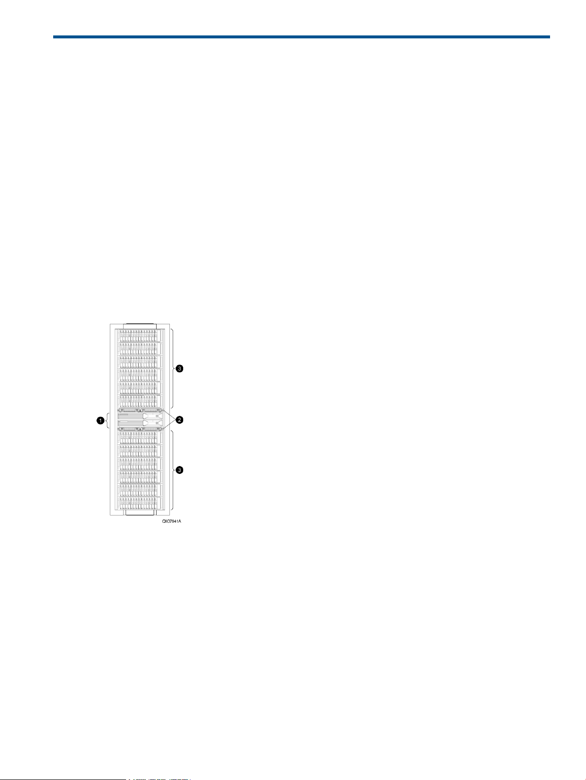
Physical layout of the storage system
The basic physical components are shown in Figure 5 (page 19). The disk drives are installed in
the disk enclosures, which connect to Fibre Channel loop switches, except on the EVA4000/4100
which does not use switches. The controller pair also connects to the loop switches.
Figure 5 Storage system hardware components
1. controllers
2. loop switches
3. disk enclosures
The EVA8000/8100, EVA6000/6100, and EVA4000/4100 are available as follows:
• EVA8000/8100 — available in multiple configurations ranging from the single-rack 2C2D
configuration to the multi-rack 2C18D. The EVA8000 includes two HSV210-A controllers and
four Fibre Channel loop switches. The EVA8100 includes two HSV210-B controllers and four
Fibre Channel loop switches.
• EVA6000/6100 — available in configurations ranging from the 2C4D configuration to the
2C8D configuration. The EVA6000 includes two HSV200-A controllers and two Fibre Channel
Physical layout of the storage system 19
Page 20
loop switches. The EVA6100 includes two HSV200-B controllers with two Fibre Channel loop
switches.
• EVA4000/4100 — available in configurations ranging from the 2C1D configuration to the
2C4D configuration without loop switches. The EVA4000 includes two HSV200-A controllers.
The EVA4100 includes two HSV200-B controllers. Multiple EVA4000/4100s can be installed
in a single rack.
See the HP 4x00/6x00/8x00 Enterprise Virtual Array Hardware Configuration Guide for more
information about configurations. See “Related information” (page 101) for links to this document.
Fibre Channel drive enclosures
The drive enclosure contains the disk drives used for data storage. A storage system includes
multiple drive enclosures. The major components of the enclosure are:
• 3U enclosure
• Dual redundant, active-to-active 2 Gbps FC loops
• 2.125-Gbps, dual loop, 14-drive enclosure
• Dual 2 Gbps FC I/O modules (A and B loops)
• Copper Fibre Channel cables
• Fibre Channel disk drives and drive blanks
• Dual redundant power supplies
• Dual redundant blowers
• Environmental Monitoring Unit (EMU)
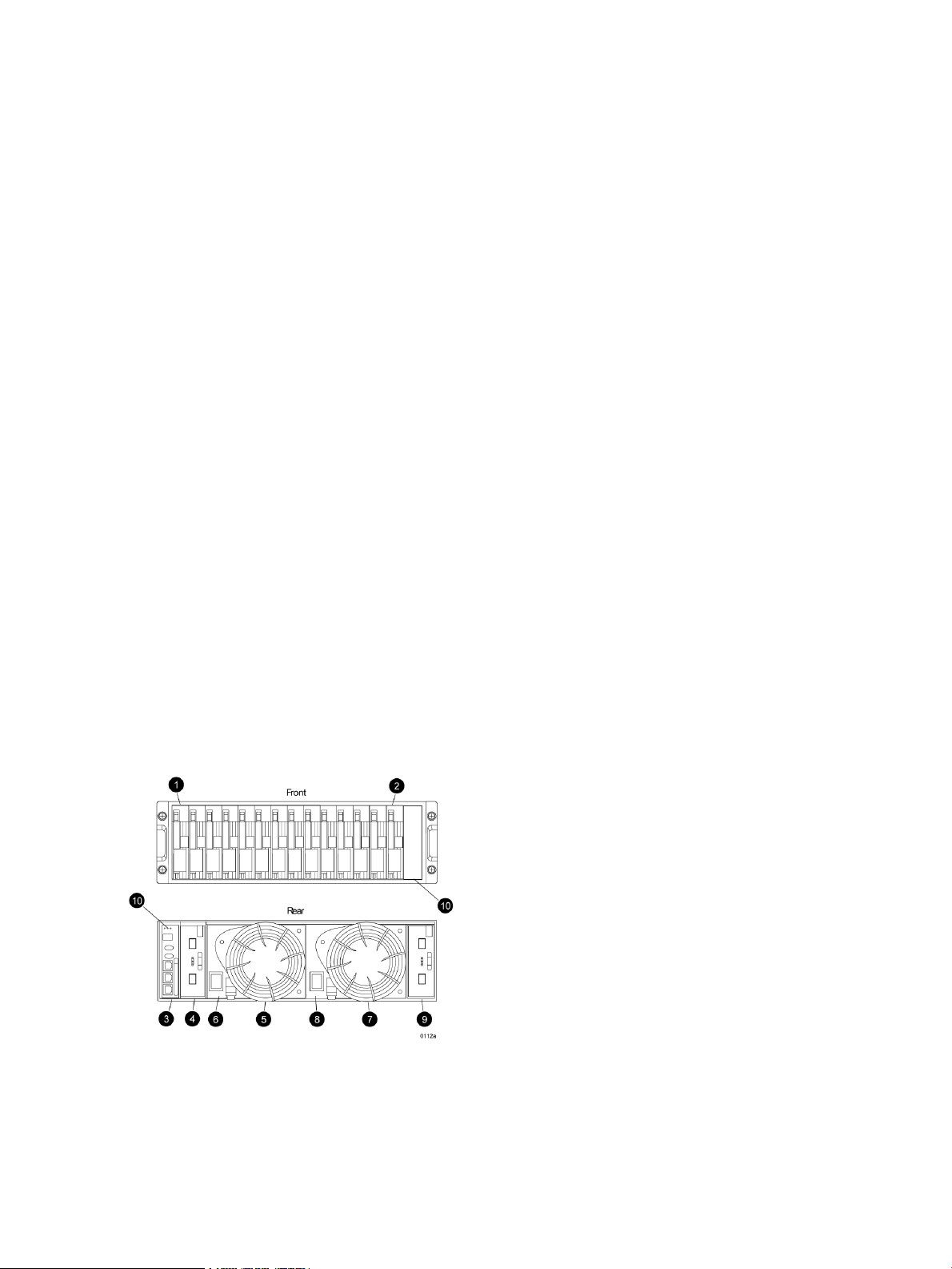
Enclosure layout
The disk drives mount in bays in the front of the enclosure. The bays are numbered sequentially
from left to right. A drive is referred to by its bay number. Enclosure status indicators are located
in the lower-right, front corner. Figure 6 (page 20) shows the front and rear views of the FC drive
enclosure.
Figure 6 FC drive enclosure—front and rear views
20 Enterprise Virtual Array hardware components
2. Drive bay 141. Drive bay 1
4. I/O module B3. EMU
6. Power supply 15. Blower 1
Page 21
9. I/O module A
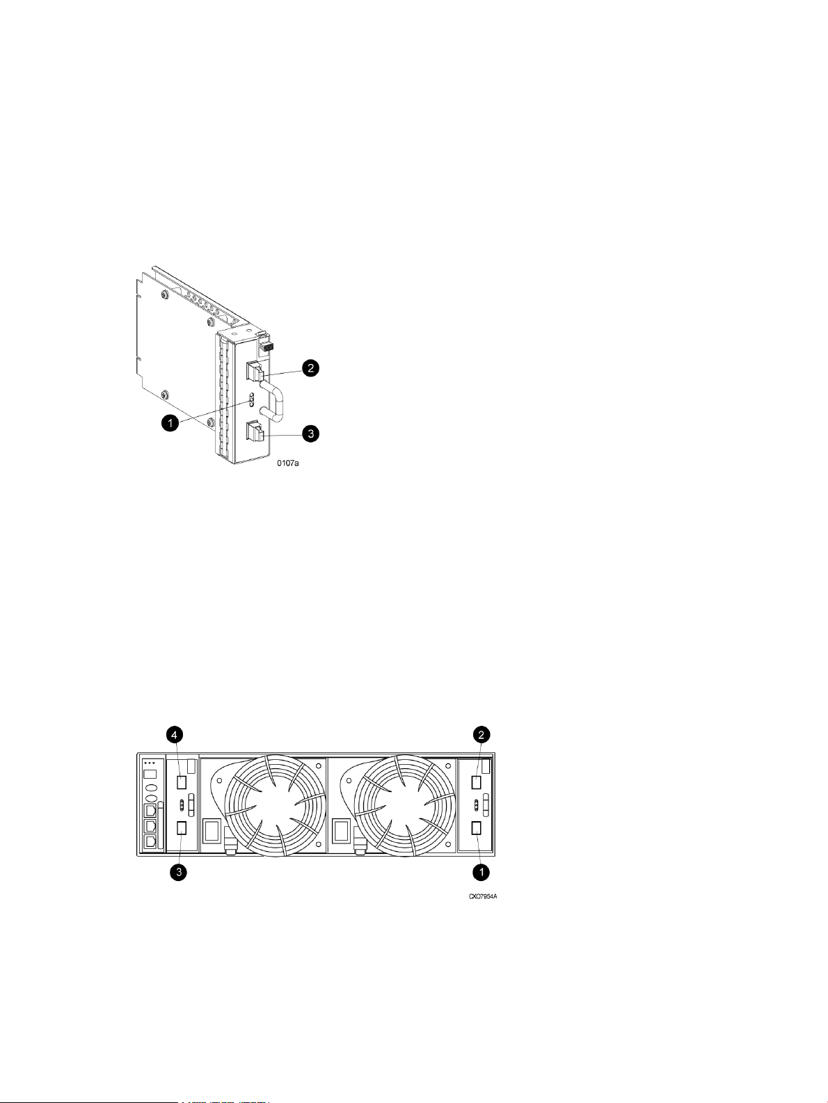
I/O modules
Two I/O modules provide the interface between the drive enclosure and the host controllers. See
Figure 7 (page 21). They route data to and from the disk drives using Loop A and Loop B, the
dual-loop configuration. For redundancy, only dual-controller, dual-loop operation is supported.
Each controller is connected to both I/O modules in the drive enclosure.
Figure 7 I/O module
8. Power supply 27. Blower 2
10. Status indicators (EMU, enclosure power, enclosure
fault)
1. Status indicators (Upper port, Power, and Lower port)
2. Upper port
3. Lower port
The I/O modules are functionally identical, but are not interchangeable. Module A can only be
installed at the right end of the enclosure, and module B can only be installed at the left end of the
enclosure. See Figure 6 (page 20).
Each I/O module has two ports that can both transmit and receive data for bidirectional operation.
Activating a port requires connecting a FC cable to the port. The port function depends upon the
loop. See Figure 8 (page 21).
Figure 8 Input and output ports
2. Loop A upper port1. Loop A lower port
4. Loop B upper port3. Loop B lower port
Fibre Channel drive enclosures 21
Page 22

I/O module status indicators
There are three status indicators on the I/O module. See Figure 7 (page 21). The status indicator
states for an operational I/O module are shown in Table 2 (page 22). Table 3 (page 22) shows
the status indicator states for a non-operational I/O module.
Table 2 Operational I/O module status indicators
DescriptionsLowerPowerUpper
OffOnOff
OnFlashing, then OnOn
OnOnOn
FlashingFlashingFlashing
• I/O Module is operational.
• Top port—Fibre Channel drive enclosure signal detected.
• Power—Flashes for about 90 seconds after initial power application,
then remains constant.
• Bottom port—Fibre Channel drive enclosure signal detected.
• Top port—Fibre Channel drive enclosure signal detected.
• Power—Present.
• Bottom port—Fibre Channel drive enclosure signal detected.
• When the locate function is active, all three indicators flash
simultaneously. The Locate function overrides all other indicator
functions. Therefore, an error could be detected while the Locate
function is active and not be indicated until the Locate action terminates.
Table 3 Non-operational I/O module status indicators
OffOnOn
• Top port—Fibre Channel drive enclosure signal detected.
• Power—Present.
• Bottom port—No Fibre Channel drive enclosure signal detected. Check
transceiver and fiber cable connections.
NOTE: This status applies to configurations with and without FC loop switches.
DescriptionsLowerPowerUpper
OnOnOff
OnOnFlashing
FlashingOnOn
OffOffOff
• Top port—No Fibre Channel drive enclosure signal detected. Check transceiver
and fiber cable connections.
• Power—Present.
• Bottom port—Fibre Channel drive enclosure signal detected .
• Top port—EMU detected possible transceiver problem. Check transceiver and
fiber cable connections.
• Power—Present.
• Bottom port—Fibre Channel drive enclosure signal detected .
• Top port—Fibre Channel drive enclosure signal detected.
• Power—Present.
• Bottom port—EMU detected possible transceiver problem. Check transceiver
and fiber cable connections.
NOTE: The EMU will not flash the lower indicator on its own. It will flash only
in response to a locate command. You can flash each of the lights independently
during a locate action.
• No I/O module power.
• I/O module is nonoperational.
• Check power supplies. If power supplies are operational, replace I/O module.
22 Enterprise Virtual Array hardware components
Page 23
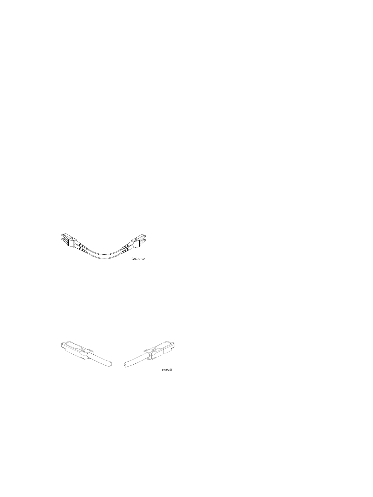
Fiber Optic Fibre Channel cables
The Enterprise Virtual Array uses orange, 50-µm, multi-mode, fiber optic cables for connection to
the SAN. The fiber optic cable assembly consists of two 2-m fiber optic strands and small form-factor
connectors on each end. See Figure 9 (page 23).
To ensure optimum operation, the fiber optic cable components require protection from
contamination and mechanical hazards. Failure to provide this protection can cause degraded
operation. Observe the following precautions when using fiber optic cables.
• To avoid breaking the fiber within the cable:
Do not kink the cable◦
◦ Do not use a cable bend-radius of less than 30 mm (1.18 in)
• To avoid deforming, or possibly breaking the fiber within the cable, do not place heavy objects
on the cable.
• To avoid contaminating the optical connectors:
Do not touch the connectors◦
◦ Never leave the connectors exposed to the air
◦ Install a dust cover on each transceiver and fiber cable connector when they are
disconnected
If an open connector is exposed to dust, or if there is any doubt about the cleanliness of the
connector, clean the connector as described in “Handling fiber optic cables” (page 71).
Figure 9 Fiber Optic Fibre Channel cable
Copper Fibre Channel cables
The Enterprise Virtual Array uses copper Fibre Channel cables to connect the drive enclosures to
each other, or to the loop switches and to the HSV controllers. The cables are available in 0.6-meter
and 2.0-meter lengths. Copper cables provide performance comparable to fiber optic cables.
Copper cable connectors differ from fiber optic small form-factor connectors (see Figure 10 (page
23)).
Figure 10 Copper Fibre Channel cable
Fibre Channel disk drives
The Fibre Channel disk drives are hot-pluggable and include the following features:
• Dual-ported 2-Gbps Fibre Channel drive enclosure interface that allows up to 120 disk drives
to be supported per Fibre Channel drive enclosure pair
• Compact, direct-connect design for maximum storage density and increased reliability and
signal integrity
• Both online high-performance disk drives and FATA disk drives in a variety of capacities and
spindle speeds
• Better vibration damping for improved performance
Fibre Channel drive enclosures 23
Page 24
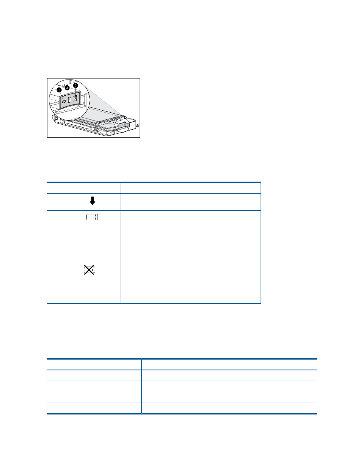
Up to 14 disk drives can be installed in a drive enclosure.
Disk drive status indicators
Three status indicators display the drive operational status. Figure 11 (page 24) shows the disk
drive status indicators. Table 4 (page 24) provides a description of each status indicator.
Figure 11 Disk drive status indicators
3. Fault
Table 4 Disk drive status indicator descriptions
2. Online1. Activity
DescriptionStatus indicator
Activity
Online
Fault
Disk drive status displays
The disk drive status indicators can assume three states: on, off, or flashing. The status indicators
states for operational drive status are shown in Table 5 (page 24). See Table 6 (page 25) for the
non-operational drive status indicator states.
Table 5 Operational disk drive status indications
This green status indicator flashes when the disk drive is being
accessed. It is on when the drive is idle.
The green status indicator is on when the disk drive is online
and operating normally. This indicator will be off in the
following situations:
• There is no controller on the bus.
• +5.1 VDC is not available.
• The drive is not properly installed in the enclosure.
This amber status indicator is on when there is a disk drive
failure. Depending on the host controller, this indicator may
flash when the controller detects an error condition.
The amber status indicator flashes in synchronization with
the other two status indicators in response to the EMU locate
command.
DescriptionFaultOnlineActivity
24 Enterprise Virtual Array hardware components
Initial startup.OffOnFlashing
The drive is online but is not being accessed.OffOnOn
The drive is being located.FlashingFlashingFlashing
The drive is operational and active.OffOnFlashing
Page 25
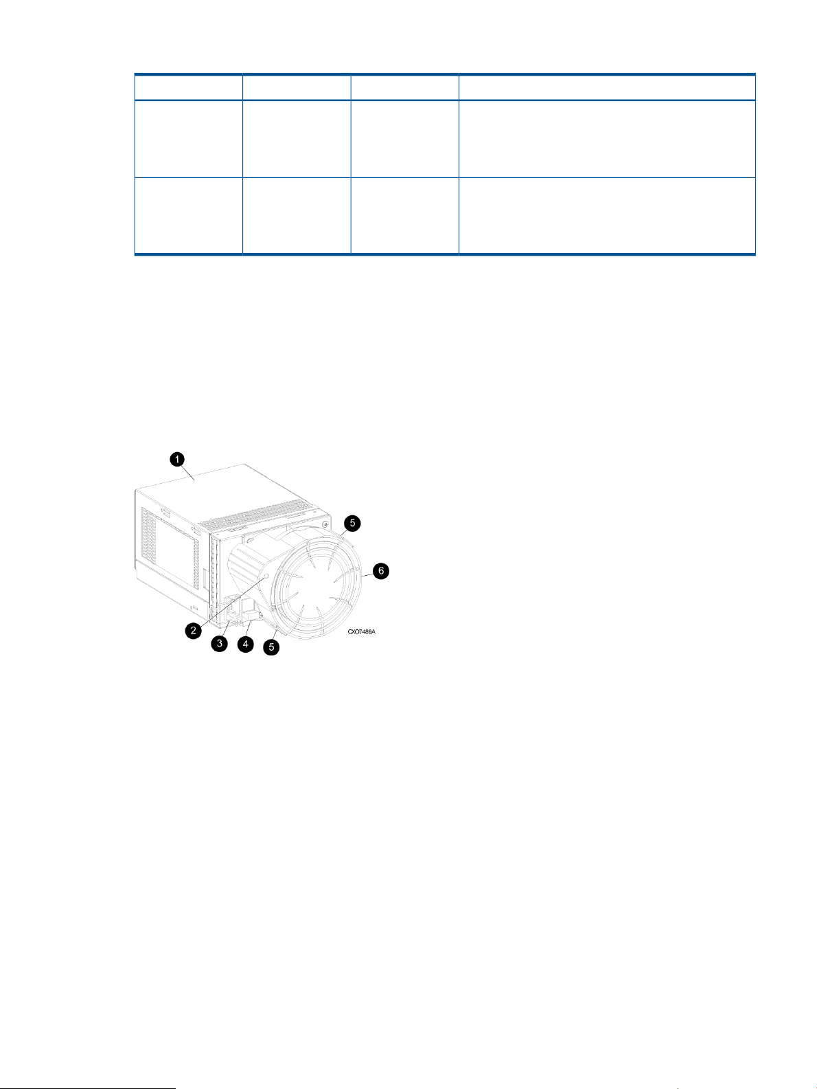
Table 6 Non-operational disk drive status indications
DescriptionFaultOnlineActivity
Disk drive blank
To maintain the proper enclosure air flow, a disk drive or a disk drive blank must be installed in
each drive bay. The disk drive blank maintains proper airflow within the disk enclosure.
Power supplies and blowers
This section describes the function and operation of the disk enclosure power supplies and blowers.
Figure 12 (page 25) illustrates the major power supply and cooling components.
Figure 12 Power supply and blower assembly components
OnOnOn
FlashingOffOn
Indicates no connection or the controllers are offline.
Recommended corrective actions:
1. Check power supplies for proper operation.
2. If defective, replace disk drive.
Indicates disk drive error/not active. Recommended
corrective actions:
1. Verify FC loop continuity.
2. Replace disk drive.
1. Power supply
2. Status indicator
3. AC Input connector with bail
4. Module latch (red wine-colored)
5. Blower tabs (red wine-colored)
6. Blower
Power supplies
The two power supplies mount in the rear of the enclosure. See Figure 23 (page 50). The supplies
are autoranging and operate on a country-specific AC input voltage of 202 to 240 VAC ±10%,
50 to 60 Hz, ±5%, (188 to 264 VAC, 47 to 63 Hz).
The DC outputs of this power supply are:
• +5.1 VDC for the EMU, I/O module, backplane, and disk drives
• +12.1 VDC for the disk drives
• +12.5 VDC for the disk drives
Fibre Channel drive enclosures 25
Page 26

Blowers
The output of each power supply is 499 W, with a peak output of 681 W. A single power supply
can support an enclosure with a full complement of disks.
The power supply circuitry provides protection against:
• Overloads
• Short circuits
• Overheating
Power supply status and diagnostic information is reported to the EMU with voltage, current, and
temperature signals.
See “Regulatory notices and specifications” (page 104) for the enclosure power specifications.
The power supply temperature sensor provides a temperature range signal to the EMU, which uses
this signal to set the blower speed.
The power supply internal temperature can also control the speed of the blower. The higher the
power supply temperature, the faster the speed of the blower. If the power supply temperature
exceeds a preset value, the power supply automatically shuts down.
The power supply-mounted blowers cool the enclosure by circulating air through the enclosure.
The blowers, under the control of the EMU or the associated power supply, can operate at multiple
speeds. This ensures that, when the enclosure temperature changes, the blowers can automatically
adjust the air flow.
If a blower is operating too slowly or has stopped (a “blower failure”), internal circuitry automatically
operates the remaining blower at a higher speed. Simultaneously, the error condition is reported
in several ways, including the power supply indicator, the audible alarm, the enclosure fault
indicators, and the EMU alphanumeric display.
Should both blowers fail, the power supplies automatically shut down.
NOTE: The blowers are field-replaceable units and can be replaced, individually, while the
system is running. The blowers are also interchangeable. The failure of a power supply +12.5
VDC circuit disables the associated blower.
The status indicator on the blower displays the status of both the power supply and the blower.
See Figure 12 (page 25). See Table 7 (page 26) for definitions of the indicator displays.
Table 7 Power supply/blower status indicators
indicator
Off
Drive enclosure EMU
The EMU provides increased protection against catastrophic failures. The EMU detects conditions
such as failed power supplies, failed blowers, elevated temperatures, and external air sense faults
and communicates these conditions to the storage system controllers.
DescriptionBlower status
Both the power supply and the blower are operational.On
The power supply or the blower locate function is active.Flashing
The power supply or the blower is non-operational. When there
is a blower problem, the other blower runs at a higher speed.
Recommended corrective actions:
• Check blower for proper operation. Replace if defective.
• Check power supplies for proper operation. Replace if
defective.
26 Enterprise Virtual Array hardware components
Page 27
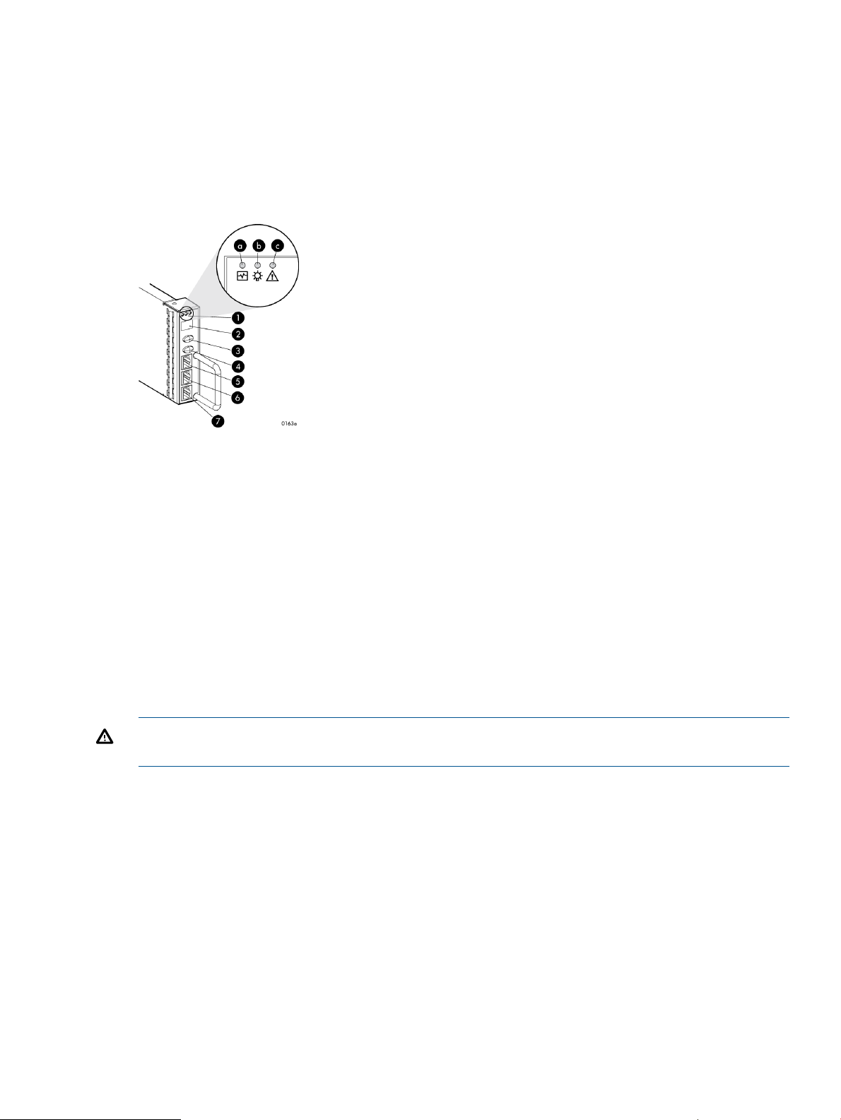
The EMU for Fibre Channel-Arbitrated Loop (FC-AL) drive enclosures is fully compliant with SCSI-3
Enclosure Services (SES), and mounts in the left rear bay of a drive enclosure. See Figure 6 (page
20).
Controls and displays
Figure 13 (page 27) illustrates the location and function of the EMU displays, controls, and
connectors.
Figure 13 EMU controls and displays
1. Status indicators:
a. EMU — This flashing green is the heartbeat for an operational EMU.
b. Enclosure power— When both the +5 VDC and +12 VDC are correct, this green indicator is on.
c. Enclosure fault — This amber indicator is normally off. The indicator is lit when an enclosure error condition exists.
2. Alphanumeric display — A two-character, seven-segment alphanumeric display of the enclosure functions and status.
3. Function select button — The primary function of this button is to select a display group function. The indicator is on
when an error condition exists.
4. Display group select button — This button is used to view display groups and control the audible alarm. The indicator
is on when the audible alarm is muted or disabled.
5. RS232 – For use by HP-authorized service representatives
6. LCD ONLY – Unused
7. CAB ONLY – Enclosure address bus connector
WARNING! To reduce the risk of electrical shock, fire, or damage to the equipment, do not plug
telephone or telecommunications connectors into the RS232 ONLY receptacle.
EMU functions
The primary functions of the EMU include:
• Using the Enclosure Services Processor (ESP) to control the Enclosure Services Interface (ESI)
• Assigning the Enclosure Number (En), based upon the cabinet address bus feature.
• Displaying the bay 1 loop ID.
• Monitoring enclosure operation.
and communicate with the controllers.
• Detecting, reporting, recording, and displaying conditions.
• Displaying EMU, enclosure, and element status.
• Implementing automatic corrective actions for some conditions.
Fibre Channel drive enclosures 27
Page 28

• Providing enclosure status data to the controllers.
• Reporting the WWN and the logical address of all disk drives.
NOTE: Although the EMU can determine the logical address of a drive, the EMU can neither
display nor change this information. HP P6000 Command View can display the addresses from
the EMU-supplied status information.
EMU monitoring functions
The internal EMU circuitry monitors the enclosure and component functions listed in Table 8 (page
28).
Table 8 EMU monitoring functions
Monitored FunctionsComponent
Blowers
Disk drives
EMU
Enclosure
I/O module
Power supplies
• Type• Installation
• •Removal Speed (rpm)
• Loop ID• Installation
• •Removal Temperature
•• Drive faultBypass status
• Type• Temperature
• •Operation Revision level
• Backplane type• Enclosure power
• •Enclosure fault Backplane revision level
• Type• Installation
• •Removal Revision level
• Status
• +5 VDC voltage and current• Installation
• •Removal +12 VDC voltage and current
•• Total powerStatus
• •Type Temperature
• Revision level
Transceiver
EMU displays
The EMU uses a combination of status indicators, alphanumeric display, and an audible alarm to
indicate the operational status of the enclosure and its components. See Table 9 (page 28).
Table 9 EMU status displays
Audible alarm (For information on the audible alarm, see “Audible
alarm operations ” (page 30).)
“EMU indicator displays” (page 29).)
Alphanumeric display (For a description of the alphanumeric
display, see “Using the alphanumeric display” (page 29).)
28 Enterprise Virtual Array hardware components
• Link status• Type
FunctionDisplay
Any EMU-detected condition causes this alarm to
sound.
Display enclosure and EMU status.Status indicators (For a description of the status indicators, see
The two-character, seven-segment display displays
alphanumeric characters.
Page 29

EMU indicator displays
The EMU status indicators are located above the alphanumeric display. See Figure 13 (page 27).
These indicators present the same information as those on the front, lower right corner of the
enclosure.
You can determine the EMU and enclosure status using the information in Table 10 (page 29).
Table 10 EMU status indications
EMU indicator (green)
Power indicator
(green)
(amber)
FlashingFlashingFlashing
OffOnFlashing
OnOnFlashing
OffOffFlashing
OffOffOff
Status and recommended actionsFault indicator
The EMU Locate function is active. This display
has precedence over all others. Fault conditions
cannot be displayed when the Locate function is
active.
The EMU is operational. The enclosure power
(both +5 VDC and +12 VDC) is present and
correct. There are no enclosure faults.
The EMU is operational. There is an enclosure
fault. Check the alphanumeric display error code
for information about the problem.
The EMU is operational. This display may be
present when power is initially applied to the
enclosure. Note: When the +5 VDC is incorrect,
all the indicators are off.
There is an EMU fault. There is no enclosure fault.OffOnOn
There is an EMU fault. There is no enclosure fault.OffOnOff
There is an enclosure fault. Either +5 VDC is
incorrect, or both +5 VDC and +12 VDC are
incorrect. Other error conditions may exist.
Using the alphanumeric display
The two-character alphanumeric display is located at the top of the EMU (see Figure 13 (page
27)). This seven-segment display provides information about multiple enclosure functions. The
push-button control the data displayed or entered.
Alphanumeric display description
The top-level, two-character alphanumeric display (En, Li, rG, Au, and Er), is the display group.
The function of the other displays is display-group dependent. The default display is the enclosure
number, a decimal number in the range 00 through 14. The push-button allow you to select the
alphanumeric display or to enter data.
• The bottom push-button sequentially moves between groups and selects a display group.
See Table 11 (page 30) for a description of these display groups.
• he top push-button moves between the levels within a display group (see 2, Figure 13 (page
27)).
Display groups
When you press and release the bottom push-button, the alphanumeric display selects a different
display group. Table 11 (page 30) describes the display groups.
Fibre Channel drive enclosures 29
Page 30

Table 11 EMU display groups
DescriptionDisplay groupDisplay
Enclosure NumberEn
Bay 1 Loop IDLi
Reporting GrouprG
Audible AlarmAu
NOTE: Any time you press and release the bottom pushbutton, the display will change to En, Li,
rG, Au, or Er.
A flashing alphanumeric display indicates that you can edit an address or state, or view a condition
report.
EMU pushbutton status indicators
The enclosure number is the default display and is a decimal number
in the range 00 through 14. See “Enclosure number feature” (page
32) for detailed information.
This display group has a single sublevel display that defines the
enclosure bay 1 loop ID. Valid loop IDs are in the range 00 through
7F.
This display group has two two-digit displays that define the reporting
group number in the range 0000 through 4095.
This display group provides control over the audible alarm or horn.
The sublevel displays are audible alarm enabled (on) or audible alarm
disabled (oF). See “Audible alarm operations ” (page 30) for detailed
information.
This display group defines the EMU code firmware version.Firmware RevisionFr
This display group reads Er when there is an error condition.Error ConditionEr
The pushbutton status indicators display error conditions and the state of the audible alarm.
• When an error condition exists, the top pushbutton status indicator is On.
For a single error condition, the status indicator is On until the error condition is viewed.◦
◦ For multiple errors, the status indicator is On until the last error condition is viewed.
• The bottom pushbutton indicator is On only when the alarm is muted or disabled.
Audible alarm operations
Whenever an error condition exists, the audible alarm automatically sounds until all errors are
corrected. You have the option of either muting or disabling the alarm.
• Disabling the audible alarm prevents it from sounding for any error condition.
• Muting the alarm silences it for the existing condition, but any new condition causes the alarm
to sound.
Audible alarm patterns
The audible alarm sound pattern differs depending on the type of error condition. See
Table 12 (page 30) for the duration and the approximate relationship of these alarms. The most
severe, active error condition controls the alarm pattern.
Table 12 Audible alarm sound patterns
Cycle 2Cycle 1Condition type
UNRECOVERABLE
CRITICAL
30 Enterprise Virtual Array hardware components
Page 31

Table 12 Audible alarm sound patterns (continued)
NONCRITICAL
INFORMATION
Legend
Cycle 2Cycle 1Condition type
Controlling the audible alarm
You can control the alarm with the push-button. This process includes muting, enabling, and
disabling. When an error condition exists, the alphanumeric display reads Er, the alarm sounds,
and you can:
• Correct all errors, thereby silencing the alarm until a new error occurs.
• Mute, or temporarily disable, the alarm by pressing and holding the bottom push-button. The
alarm remains off until another error occurs, or until you enable (unmute) the alarm. When a
new error occurs, the alarm sounds and the push-button indicator is off.
Using the mute feature ensures that you are aware of the more severe errors and provides
you with the capability of correcting them promptly.
• Disable the alarm to prevent any error condition from sounding the alarm.
NOTE: Disabling the alarm does not prevent the EMU alphanumeric display from displaying Er,
nor does it prevent HP P6000 Command View from displaying the error condition report.
When the alarm is enabled (on), the bottom push-button status indicator is off.
Enabling the audible alarm
To enable the alarm:
1. Press and release the bottom push-button until the alphanumeric display is Au.
2. Press and hold the top push-button until the alphanumeric display is a Flashing oF (Audible
Alarm Off).
Alarm On
Alarm Off
NOTE: When the alarm display is flashing, press and hold the top push-button to cause the
display to toggle between On and oF. Press and release the top push-button to cause the
display to select the next state.
3. Press and release the top push-button to change the display to a flashing On (Audible Alarm
On).
4. Press and release the bottom push-button to accept the change and to display Au. The bottom
push-button indicator is now off.
Muting or unmuting the audible alarm
You may want to mute the alarm in the following situations:
• The error does not require immediate corrective action.
• You cannot correct the error at this time. For example, the error may require a replacement
part.
To mute the audible alarm:
Fibre Channel drive enclosures 31
Page 32

NOTE: Er is displayed in the alphanumeric display when an error condition is present.
1. Press and hold the bottom push-button until the status indicator is On.
A muted alarm will remain off until a new condition report exists.
2. To unmute the alarm, press and hold the bottom push-button until the status indicator is Off.
When a new error condition occurs, the alarm will sound.
Disabling the audible alarm
CAUTION: Disabling the audible alarm increases the potential of damage to equipment from a
reported but unobserved fault. HP does not recommend disabling the audible alarm.
Disabling the audible alarm affects only one enclosure. This action does not affect condition report
displays on the EMU alphanumeric display or errors reported by HP P6000 Command View.
To disable the alarm:
1. Press and release the bottom push-button until the alphanumeric display is Au.
2. Press and hold the top push-button until the alphanumeric display is a Flashing on (Audible
Alarm On).
NOTE: When the alarm display is flashing, pressing and holding the top push-button causes
the display to rapidly change between on and oF and also causes the display to select the
next state.
3. Press and release the top push-button to change the display to a Flashing oF (Audible Alarm
Off).
4. Press and release the bottom push-button to accept the change and display Au. The bottom
push-button indicator is now on.
NOTE: A disabled audible alarm (the bottom push-button indicator is on) cannot sound for
any error condition. To ensure that you are immediately alerted to error conditions, it is
recommended that the alarm mute function be used rather than the alarm disable function. If
you must use the disable function, remember to enable the audible alarm as soon as possible
to ensure that you are alerted to errors.
Enclosure number feature
This section provides a description of the purpose, function, and operation of the EMU enclosure
number (En) feature.
En description
In a single rack configuration, the En is a decimal number in the range 00 through 14, which is
automatically assigned by the enclosure address bus.
NOTE: Your storage system may use an enclosure address bus higher than 14 if your configuration
includes an optional expansion cabinet. The enclosure address bus connection determines the En.
For a single rack, the display is a decimal number in the range 01 through 14. For a multiple (two)
rack configuration, the display is decimal number in the range 01 through 24.
By default, the two-character alphanumeric display shows this number. Pressing the bottom
push-button changes the display to En, the En display mode.
When the display is En, pressing and releasing the top push-button displays the enclosure number.
A display of 00 indicates that the enclosure is not connected to the enclosure address bus. When
this condition exists, there is no EMU-to-EMU communication over the enclosure address bus.
32 Enterprise Virtual Array hardware components
Page 33

A display of 01 through 14 indicates that the enclosure is connected to the enclosure address bus
and can exchange information with other enclosures on the enclosure address bus. The decimal
number indicates the physical position of the enclosure in relation to the bottom of the rack.
• 01 is the address of the enclosure connected to the lower connector in the first (lower) enclosure
ID expansion cable.
• 14 is the address of the enclosure closest to end of the bus, the upper connector in the last
(upper) ID expansion cable.
Unless there is an error condition, the display automatically returns to the enclosure number (01
through 14) one minute after a push-button was last pressed.
Enclosure address bus
The enclosure address bus provides a means for managing and reporting environmental conditions
within the rack. It is composed of enclosure ID expansion cables that interconnect the drive enclosures
and controller enclosures. Two drive enclosures connect to each enclosure ID expansion cable.
The drive enclosure numbers are always assigned by the enclosure address bus. Connecting the
EMU CAB connector to an enclosure address bus enclosure ID expansion cable automatically
establishes an enclosure number of 01 through 14. Any drive enclosure not connected to the
enclosure address bus has the enclosure number 00.
NOTE: The enclosure number is automatically assigned. You cannot manually assign an enclosure
number.
The enclosures are numbered as shown in Figure 14 (page 33).
Figure 14 Enclosure numbering with enclosure ID expansion cables
NOTE: If an expansion rack is used, the enclosure numbering shown above may change or
contain additional numbering. See the HP Enterprise Virtual Array Hardware Configuration Guide
for more information.
For more information about the reporting group number, see “Reporting group feature” (page 37).
Fibre Channel drive enclosures 33
Page 34

Enclosure address bus connections
Connecting the enclosures to the enclosure ID expansion cables establishes the enclosure address
bus. The enclosures are automatically numbered based on the enclosure ID expansion cable to
which they are connected. Figure 15 (page 34) shows the typical configuration of a 42U cabinet
with 14 enclosures.
Figure 15 Enclosure address bus components with enclosure ID expansion cables
13. Shelf ID expansion cable port 13—Disk enclosure 13
Error Condition Reporting
The EMU constantly monitors enclosure operation and notifies you of conditions that could affect
operation. When an error condition is detected, the following action is taken:
• The EMU alphanumeric display is changed to Er. A condition report has precedence over all
other displays.
• The audible alarm sounds (if it is not disabled).
• The error is stored in the error queue.
• The error is passed to the controllers for processing and display by HP Command View EVA.
NOTE: An error always generates a condition report. Not all condition reports are generated
by errors.
2. Shelf ID expansion cable port 2—Disk enclosure 21. Shelf ID expansion cable port 1—Disk enclosure 1
4. Shelf ID expansion cable port 4—Disk enclosure 43. Shelf ID expansion cable port 3—Disk enclosure 3
6. Shelf ID expansion cable port 6—Disk enclosure 65. Shelf ID expansion cable port 5—Disk enclosure 5
8. Shelf ID expansion cable port 8—Disk enclosure 87. Shelf ID expansion cable port 7—Controller enclosures
10. Shelf ID expansion cable port 10—Disk enclosure 109. Shelf ID expansion cable port 9—Disk enclosure 9
12. Shelf ID expansion cable port 12—Disk enclosure 1211. Shelf ID expansion cable port 11—Disk enclosure 11
34 Enterprise Virtual Array hardware components
Page 35

Error condition categories
Each error condition is assigned to a category based on its impact on disk enclosure operation.
The following four error categories are used:
• Unrecoverable — the most severe error condition, it occurs when one or more enclosure
components have failed and have disabled some enclosure functions. The enclosure may be
incapable of correcting, or bypassing the failure, and requires repairs to correct the error.
NOTE: To maintain data integrity, corrective action should be implemented immediately for
an UNRECOVERABLE condition.
• Critical — occurs when one or more enclosure components have failed or are operating
outside of their specifications. The failures impact the normal operation of some components
in the enclosure. Other components within the enclosure may be able to continue normal
operations. Prompt corrective action should be taken to prevent system degradation.
• Noncritical — occurs when one or more components inside the enclosure have failed or are
operating outside of their specifications. The failure of these components does not impact
continued normal operation of the enclosure. All components in the enclosure continue to
operate according to their specifications. The ability of the components to operate correctly
may be reduced should other errors occur. Prompt corrective action should be taken to prevent
system degradation.
• Information — the least severe condition indicates a condition exists that does not reduce the
capability of a component. However, the condition can become an error and require corrective
action. An INFORMATION condition provides an early warning, which enables you to prepare
to implement corrective action before a component fails. Correction of the reported problem
may be delayed.
The error conditions are prioritized by severity—from most severe to least. The most severe condition
takes precedence and is reported first when multiple errors are detected. The reporting characteristics
for each error condition are listed in Table 13 (page 35).
Table 13 Error condition reporting characteristics
Takes precedence overError condition
1
The pattern occurs when the condition is the most severe active condition.
Audible alarm pattern
On continuouslyAll other conditionsUNRECOVERABLE
Sounds three times per alarm cycleNONCRITICAL and INFORMATIONCRITICAL
Sounds two times per alarm cycleINFORMATIONNONCRITICAL
Sounds once per alarm cycleNo other conditionsINFORMATION
1
Error queue
The EMU maintains an internal error queue for storing error conditions. Each error condition remains
in the error queue until the problem is corrected, or for at least 15 seconds after the error is reported.
This ensures that, when there are multiple errors or a recurring error, each can be displayed. Each
entry in the error queue can be displayed using a combination of the top and bottom buttons. Each
error entry in the queue contains the element type, the element number, and the error code.
Correcting the error removes the associated condition from the error queue. Replacing the EMU
will also clear the error conditions. The order in which the EMU displays the error queue information
is based on two factors:
• The severity of the error
• The time the error occurred
Fibre Channel drive enclosures 35
Page 36

The most severe error in the queue always has precedence, regardless of how long less severe
errors have been in the queue. This ensures that the most severe errors are displayed immediately.
NOTE: When viewing an error, the occurrence of a more severe error takes precedence and
the display changes to the most severe error.
The earliest reported condition within an error type has precedence over errors reported later. For
example, if errors at all levels have occurred, the EMU displays them in the following order:
1. UNRECOVERABLE errors in the sequence they occurred.
2. CRITICAL errors in the sequence they occurred.
3. NONCRITICAL errors in the sequence they occurred.
4. INFORMATION conditions in the sequence they occurred.
Error condition report format
Each EMU detected condition generates a condition report containing three pieces of information.
• Element type The first two-digit hexadecimal display defines the element type reporting the
problem. The format for this display is e.t. with a period after each character. Valid element
types are 0.1. through F.F.
• Element number The second display is a two-digit decimal number that defines the specific
element reporting the problem. The format for this display is en. with a period after the second
character.
• Error code The third display is a two-digit decimal number that defines the specific error code.
The format for this display is ec without any periods.
For detailed information about each condition report, including recommended corrective actions,
see “EMU-generated condition reports” (page 117).
Navigating the error condition display
When an error condition occurs, the alphanumeric display changes to Er and the error menu is
active. The buttons are used to display the error condition values.
Perform the following procedure to display error conditions. Figure 16 (page 37) illustrates the
sequence for displaying error conditions.
1. With Er in the display, press and hold the top push-button until the first element type is
displayed. The most severe error in the queue will be displayed.
2. Release the top push-button when the element type is displayed. The element type has both
decimal points lit.
3. Press and release the top push-button to display the element number. This display has only
the right decimal point lit.
4. Press and release the top push-button again to display the error code. This display has no
decimal points lit. Repeated press/release operations will cycle through these three values.
5. Press and hold the top push-button from any of the three display states to move to the element
type for the next error condition in the queue.
6. Use the top push-button to display the values for the error condition.
7. When all error conditions have been displayed, press and release the bottom pushbutton to
return to the Er display.
36 Enterprise Virtual Array hardware components
Page 37

Figure 16 Displaying error condition values
Press and hold top push-button to view first error in queue.1
Press and release top push-button.2
Press and hold top push-button to view next error.3
Press and release the bottom push-button at any time to return to the Er display.4
e.t. = element type, en. = element number, ec = error code
Analyzing condition reports
Analyzing each error condition report involves three steps:
1. Identifying the element.
2. Determining the major problem.
3. Defining additional problem information.
Reporting group feature
Another function of the enclosure address bus is to provide communications within a reporting
group. A Reporting Group (rG) is an HSV controller pair and the associated drive enclosures. The
controller pair automatically assigns a unique (decimal) four-digit Reporting Group Number (RGN)
to each EMU on a Fibre Channel drive enclosure.
Each of the drive enclosures on a loop pair are in one reporting group:
• All of the drive enclosures on loop pair 1, both loop 1A and loop 1B, share a unique reporting
group number.
• All of the drive enclosures on loop pair 2, both loop 2A and loop 2B, share a unique reporting
group number.
Each EMU collects environmental information from the associated enclosure and broadcasts the
information to reporting group members using the enclosure address bus. Information from enclosures
in other reporting groups is ignored.
Reporting group numbers
The reporting group number (RGN) range is 0000 through 4099, decimal.
• 0000 is reserved for enclosures that are not part of any reporting group.
• 0001 through 0015 are RGNs reserved for use by the EMU.
• 0016 through 4095 are valid RGNs.
• 4096 through 4099 are invalid RGNs.
Fibre Channel drive enclosures 37
Page 38

The reporting group numbers are displayed on the EMU alphanumeric display as a pair of two-digit
displays. These two displays are identified as rH and rL.
• Valid rH displays are in the range 00 through 40, and represent the high-order (most significant)
two digits of the RGN.
• Valid rL displays are in the range 00 through 99, and represent the low-order (least significant)
two digits of the RGN.
To view a reporting group number:
1. Press and release the bottom push-button until the alphanumeric display is rG.
2. To display the two most significant digits of the Reporting Group Number, press and hold the
top pushbutton unit the display is rH.
3. Press and release the top push-button to display the first two digits of the RGN.
4. Press and release the top push-button until the alphanumeric display is rH.
5. Press and hold the top push-button until the alphanumeric display is rL.
6. Press and release the top push-button to display the last two digits of the Reporting Group
Number.
7. To exit the display, press and release the bottom push-button until the alphanumeric display
is rG.
Fibre Channel loop switches
The loop switches act as a central point of interconnection and establish a fault-tolerant physical
loop topology between the controllers and the disk enclosures. The loop switches are required in
any configuration with more than four disk enclosures. The EVA8000/8100 uses four loop switches
and the EVA6000/6100 uses two switches to connect the drive enclosures to the controller pair.
The loop switches provide the following features:
• 2.125-Gbps operating speed
• Twelve ports
• Half-width, 1U size
• System and port status indicators
• Universal power supply that operates between 100 to 250 VAC and 50 to 60 Hz
NOTE: Each bezel covers two FC loop switches in a space of 1U.
The EVA8000 uses four loop switches to connect all of the drive enclosures to the controller pair
using FC cables. The EVA 6000 includes two loop switches. Each switch acts as a central point
of interconnection and establishes a fault-tolerant physical loop topology. The EVA6100/8100
use the 30-10022-01 loop switch only.
The half-rack form factor switch is controlled by firmware loaded into the on-board flash memory.
The switch is designed as a central interconnect following the ANSI FC-AL standard. Disk enclosures
are connected to the switch through Small Form-factor Pluggable (SFP) transceivers and cables.
The storage system uses one of the following loop switches:
• 30-10022-01 loop switch–used with 2 Gb and 4 Gb controllers (requires XCS 5.110 or later)
• 30-10010-02 loop switch–used with 2 Gb and 4Gb controllers
30-10022-01 loop switch
The 30-10022-01 loop switch contains both system indicators and port indicators. The system
indicators indicate the status of the switch, and the port indicators provide status of a specific port.
Figure 17 (page 39) shows the 30-10022-01 loop switch with the system and port indicators.
38 Enterprise Virtual Array hardware components
Page 39

Figure 17 30-10022-01 loop switch status indicators
1. Ethernet activity
2. Ethernet link
3. Port status
4. System status
Power
Fault
Temp
Power-on self test (POST)
• Flashing—the Ethernet port is receiving data.
• Flashing rapidly—the traffic level is high.
• On—the port is connected to an operational Ethernet.
• Off—SFP is not installed in the port.
• On (green)—Normal port operational status when an SFP is installed and a link has been
established.
• On (yellow)—port has an SFP installed but a link has not been established.
• Flashing (green)—activity. Data is being transferred between the port and device.
• On—the switch is plugged in and the internal power supply is functional.
• On—an event has occurred that meets or exceeds the current Fault threshold setting. The
default Fault threshold setting is critical. The switch will continue to operate. Switch
functionality may be impaired depending on the event that triggered the Fault condition.
Regardless of the cause, the switch requires immediate attention.
• On—the internal temperature has exceeded acceptable levels. The switch will continue to
operate. Switch functionality may be impaired depending on the event that triggered the
Temp condition. Regardless of the cause, the switch requires immediate attention.
When the switch powers on, it runs Power-On Self-Test (POST) diagnostics to verify the fundamental
integrity of the switch ports. All switch LEDs turn on (LEDs illuminate). Then, excluding the Ethernet
Link and Power LEDs, the LEDs turn off (LEDs extinguish). Once the switch is operational, the LEDs
display current status. See Figure 17 (page 39).
30-10010-02 loop switch
The 30-10010-02 loop switch contains both system indicators and port indicators. The system
indicators indicate the status of the switch, and the port indicators provide status of a specific port.
Figure 18 (page 40) shows the 30-10010-02 loop switch with the system and port indicators.
The Fibre Channel loop switch acts as a central point of interconnection and establishes a
fault-tolerant physical loop topology between the controllers and the disk enclosures.
Fibre Channel loop switches 39
Page 40

Figure 18 30-10010-02 loop switch status indicators
2. Bezel snaps1. Handle
4. Walk-up RS232 port3. Alignment tabs
6. Port Bypassed indicator5. SFP status indicator
8. Over Temp indicator7. POST fault indicator
10. Loop operational indicator9. Power indicator
Power-on self test (POST)
When you power on the 30-10010-02 loop switch, it performs a Power-on Self Test (POST) to
verify that the switch is functioning properly. During a POST, all of the indicators turn on for
approximately two seconds. Then, turn off all of the indicators, except the power indicator.
If the Port Bypass indicators are blinking at a constant rate and the POST Fault indicator is on, the
switch detected a fault during the POST. In this case, you need to contact your HP authorized
service representative.
Reading the switch status indicators
Figure 18 (page 40) shows the Fibre Channel switch with the system and port indicators.
Table 14 (page 40) lists and describes the system indicators.
Table 14 30-10010-02 loop switch status indicators
Power
Loop operational
POST fault
OverTemp
A green indicator. When lit, this indicates that the switch is plugged in and the internal
power is functional.
A green indicator. When lit, this indicates that the Fibre Channel loop has completed
initialization and is now operational.
An amber indicator. When lit, this indicates that the internal hardware self-test failed
and the switch will not function.
An amber indicator. When lit, this indicates that the ambient temperature has exceeded
40° C. The switch is still functional; however, you should correct the problem immediately.
The OverTemp indicator turns off when the problem is corrected.
DescriptionSystem indicator
Table 15 (page 41) describes the port indicators.
40 Enterprise Virtual Array hardware components
Page 41

Table 15 30-10010-02 loop switch port status indicators
SFP status
indicator (Green)
Problem isolation
Table 16 (page 41) lists several basic problems and their solutions.
Table 16 30-10010-02 loop switch basic troubleshooting
(Amber)
OffOff
OffOn
OnOn
OnOff
DescriptionPort bypass indicator
Indicates that the port does not have an SFP installed and is bypassed
by the loop.
Indicates that the port is operating normally. The port and device are
fully operational.
Indicates the that port is in a bypassed state. The port is non-operational
due to loss of signal, poor signal integrity, or the Loop Initialization
Procedure (LIP).
NOTE: This condition is also normal when the SFP is present but not
attached to a Fibre Channel drive enclosure node, or when the SFP is
present and attached to only a cable assembly. Attaching the SFP to a
device and plugging it into the port should initiate the LIP by the attached
device.
Indicates a Tx fault. The port is non-operational due to an SFP transmitter
fault, improperly-seated SFP, or another failed device.
Recommended actionProblem
SFPs are installed in ports but no indicators
are lit.
SFP is installed, but the Port Bypassed
indicator is lit.
SFP is installed, but the SFP status indicator
and the Port Bypassed indicator are lit.
SFP is installed and the SFP status indicator
is lit, but the devices are not communicating.
1. Verify that the power cord is firmly seated in the switch and is
connected to the power outlet.
2. Check the power indicator to verify that the switch is on.
Re-seat the SFP. If the same condition occurs, the SFP is probably faulty
and should be replaced.
This condition indicates that the switch is not receiving a valid Fibre
Channel signal or that the switch is receiving an LIP.
1. Ensure that the switch is powered on.
2. Contact your HP authorized service representative for further
assistance.
This condition indicates that the switch is receiving a valid Fibre Channel
signal, but there are no upper level protocols active.
1. Verify that you are running the correct firmware on all storage system
hardware.
2. Check the Loop Operational indicator.
a. If the Loop Operational indicator is lit, the devices have completed
initialization.
b. If the Loop Operational indicator is off, the devices were not
initialized. Disconnect the devices from the switch. Reconnect the
devices one at a time. This allows you to isolate the device that
is responsible for the loop failure.
3. Contact your authorized service representative for further assistance.
HSV controllers
Two controllers (HSV210-A/B or HSV200-A/B) are contained in each rack. Each controller is
contained in a separate controller and provides the following features:
• High-performance microprocessor
• An Operator Control Panel (OCP)
HSV controllers 41
Page 42

• Four 4 Gbps Fibre Channel-Switched fabric host ports (two host ports in HSV200-A or
HSV200-B controller)
• Four 2 Gbps Fibre Channel drive enclosure device ports (two device ports in HSV200-A or
HSV200- B controller)
◦ Arranged in redundant pairs
◦ Data load/performance balanced across a pair
◦ Support for up to 240 disks with HSV210-A or HSV210-B and 112 with HSV200-A or
HSV200- B
• 2 GB cache per controller, mirrored, with battery backup (1-GB cache in HSV200-A or
HSV200- B controller)
• 2 Gbps FC cache mirroring ports with device port backups
• Dual power supplies
In addition to managing the operation of the storage system, the HSV controllers serve as the
interface between the storage system hardware and the SAN. All host I/Os and all HP P6000
Command View management commands are processed by the controllers. Up to 18 drive enclosures
are supported by one controller pair.
Figure 19 (page 42) shows the HSV210-A/B controller rear view. Figure 20 (page 43) shows the
HSV200-A/B controller rear view. The front view of both controllers is shown in Figure 21 (page
43).
NOTE: The EVA4000/6000/8000 and EVA4100/6100/8100 use controllers with 2 Gb and
4 Gb host port capability. The 4 Gb controller can be distinguished from the earlier 2 Gb controllers
by the “-A” and “-B” suffixes used on the controller bezel. The 4 Gb EVA4000 and EVA6000
controllers are identified as the HSV200-A. The 4 Gb EVA4100 and EVA6100 are identified as
HSV200-B. The 4 Gb EVA8000 is identified as the HSV210-A and the 4 Gb EVA8100 is identified
as HSV210-B.
IMPORTANT: To upgrade from an HSV200-A or HSV210-A controller to an HSV200-B or
HSV210-B controller, HP requires that you also upgrade the I/O modules (A and B) to AD623C
and AD624C on each shelf. If you are upgrading to an EVA6100 (HSV200-B) or EVA8100
(HSV210-B) and you do not already have the 30-10022-01 loop switches installed, you must also
upgrade the loop switches to 30-10022-01.
Figure 19 HSV210-A/B controller—rear view
42 Enterprise Virtual Array hardware components
2. CAB (cabinet address bus)1. Dual controller interconnect
4. Power ON3. Unit ID
6. FC cache mirror ports5. FC device ports
8. Power supply 07. FC host ports
10. Service connectors (not for customer use)9. Power supply 1
Page 43

Figure 20 HSV200-A/B controller—rear view
Figure 21 HSV controller—front view
2. CAB (cabinet address bus)1. Dual controller interconnect
4. Power ON3. Unit ID
6. FC cache mirror ports5. FC device ports
8. Power supply 07. FC host ports
10. Service connectors (not for customer use)9. Power supply 1
7. Unit ID
High availability features
Two interconnected controllers ensure that the failure of a controller component does not disable
the system. A single controller can fully support an entire system until the defective controller, or
controller component, is repaired. For EVA8x00 configurations with more than four disk drive
enclosures, the complete data redundancy configuration includes device loop switches on the two
Loop A and two Loop B data paths. For EVA4x00 and EVA6x00 configurations, data redundancy
is accomplished with device loop switches on the two Loop A data paths.
Each HSV210-A/B controller has two lead-acid cache batteries that provide power to the cache
memory. Each HSV200-A/B controller has one battery. When the batteries are fully charged, they
can provide power to the cache for up to 96 hours.
Operator control panel
The operator control panel (OCP) provides a direct interface to each controller. From the OCP you
can display storage system status and configuration information, shut down the storage system,
and manage the password.
The OCP includes a 40-character LCD alphanumeric display, six push-buttons, and five status
indicators. See Figure 22 (page 44).
2. Battery 1 (EVA8000/8100 only)1. Battery 0
4. Blower 13. Blower 0
6. Status indicators5. Operator Control Panel (OCP)
HP Command View EVA is the tool you will typically use to display storage system status and
configuration information or perform the tasks available from the OCP. However, if HP P6000
Command View is not available, the OCP can be used to perform these tasks.
HSV controllers 43
Page 44

Figure 22 Controller OCP
1. Status indicators (see Table 17 (page 44)) and UID button
2. 40-character alphanumeric display
3. Left, right, top, and bottom push-buttons
4. Esc
5. Enter
Status indicators
The status indicators display the operational status of the controller. The function of each indicator
is described in Table 17 (page 44). During initial setup, the status indicators might not be fully
operational.
The following sections define the alphanumeric display modes, including the possible displays,
the valid status indicator displays, and the pushbutton functions.
Table 17 Controller status indicators
DescriptionIndicator
When this indicator is on, there is a controller problem. Check either HP P6000 Command
Fault
Controller
Physical link to hosts
established
Virtual disks presented to
hosts
Cache Battery Assembly
Unit ID
View or the LCD Fault Management displays for a definition of the problem and
recommended corrective action.
When this indicator is flashing slowly, a heartbeat, the controller is operating normally.
When this indicator is not flashing, there is a problem.
When this indicator is green, there is at least one physical link between the storage
system and hosts that is active and functioning normally. When this indicator is off, there
are no links between the storage system and hosts that are active and functioning
normally.
When this indicator is green, all virtual disks that are presented to hosts are healthy and
functioning normally. When this indicator is amber, at least one virtual disk is not
functioning normally. When this indicator is off, there are no virtual disks presented to
hosts and this indicates a problem with the Vdisk on the array.
When this indicator is off, the battery assembly is charged. When this indicator is on,
the battery assembly is discharged.
Press to light the blue LED on the front and back of the controller. This indicator comes
on in response to a Locate command issued by HP P6000 Command View.
Each port on the rear of the controller has an associated status indicator located directly above it.
Table 18 (page 45) lists the port and its status description.
44 Enterprise Virtual Array hardware components
Page 45

Table 18 Controller port status indicators
DescriptionPort
Fibre Channel host ports
Fibre Channel device ports
Fibre Channel cache mirror ports
Dual controller interconnect port
1
On copper Fibre Channel cables, the SFP is integrated into the cable connector.
Navigation buttons
The operation of the navigation buttons is determined by the current display and location in the
menu structure. Table 19 (page 45) defines the basic pushbutton functions when navigating the
menus and options.
To simplify presentation and to avoid confusion, the pushbutton reference names, regardless of
labels, are left, right, top, and bottom.
• Green—Normal operation
• Amber—No signal detected
• Off—No SFP1detected or the Direct Connect OCP setting is incorrect
• Green—Normal operation
• Amber—No signal detected or the controller has failed the port
• Off—No SFP1detected
• Green—Normal operation
• Amber—No signal detected or the controller has failed the port
• Off—No SFP1detected
• Green—Normal operation
• Amber—Interconnect cable not connected
Table 19 Navigation button functions
Alphanumeric display
The alphanumeric display uses two LCD rows, each capable of displaying up to 20 alphanumeric
characters. By default, the alphanumeric display alternates between displaying the Storage System
Name and the World Wide Name. An active (flashing) display, an error condition message, or
a user entry (pressing a push-button) overrides the default display. When none of these conditions
exist, the default display returns after approximately 10 seconds.
FunctionButton
Moves down through the available menus and options
Moves up through the available menus and options
Selects the displayed menu or option.
Returns to the previous menu.
Used for “No” selections and to return to the default display.Esc
Used for “Yes” selections and to progress through menu items.Enter
Displaying the OCP menu tree
The Storage System Menu Tree lets you select information to be displayed, configuration settings
to change, or procedures to implement. To enter the menu tree, press any navigation push-button
when the default display is active.
HSV controllers 45
Page 46

The menu tree is organized into the following major menus:
• System Info—displays information and configuration settings.
• Fault Management—displays fault information. Information about the Fault Management menu
is included in “Controller fault management” (page 135).
• Shutdown Options—initiates the procedure for shutting down the system in a logical, sequential
manner. Using the shutdown procedures maintains data integrity and avoids the possibility
of losing or corrupting data.
• System Password—create a system password to ensure that only authorized personnel can
manage the storage system using HP P6000 Command View.
To enter and navigate the storage system menu tree:
1. Press any push-button while the default display is in view. System Information becomes the
active display.
2. Press to sequence down through the menus.
Press to sequence up through the menus.
Press to select the displayed menu.
Press to return to the previous menu.
NOTE: To exit any menu, press Esc or wait ten seconds for the OCP display to return to the default
display.
Table 20 (page 46) identifies all the menu options available within the OCP display.
CAUTION: Many of the configuration settings available through the OCP impact the operating
characteristics of the storage system. You should not change any setting unless you understand
how it will impact system operation. For more information on the OCP settings, contact your
HP-authorized service representative.
Table 20 Menu options within the OCP display
System PasswordShutdown OptionsFault ManagementSystem Information
Change PasswordRestartLast FaultVersions
Clear PasswordPower OffDetail ViewHost Port Config
(Sets Fabric or Direct
Connect)
Uninitialize SystemDevice Port Config
(Enables/disables device
ports)
IO Module Config
(Enables/disables
auto-bypass)
Loop Recovery Config
(Enables/disables recoveries)
Current Password
(Set or not)
Unbypass Devices
UUID Unique Half
Debug Flags
Print Flags
Mastership Status (Displays
controller role — master or
slave)
46 Enterprise Virtual Array hardware components
Page 47

Displaying system information
NOTE: The purpose of this information is to assist the HP-authorized service representative when
servicing your system.
The system information displays show the system configuration, including the XCS version, the OCP
firmware and application programming interface (API) versions, and the enclosure address bus
programmable integrated circuit (PIC) configuration. You can only view, not change, this information.
Displaying versions system information
When you press , the active display is Versions. From the Versions display you can determine
the:
• OCP firmware version
• Controller version
• XCS version
NOTE: The terms PPC, Sprite, Glue, SDC, CBIC, and Atlantis are for development purposes and
have no significance for normal operation.
NOTE: When viewing the software or firmware version information, pressing displays the
Versions Menu tree.
To display System Information:
1. The default display alternates between the Storage System Name display and the World Wide
Name display.
Press any push-button to display the Storage System Menu Tree.
2. Press until the desired Versions Menu option appears, and then press or to move to
submenu items.
Shutting down the system
CAUTION: To power off the system for more than 96 hours, use HP P6000 Command View.
You can use the Shutdown System function to implement the shutdown methods listed below. These
shutdown methods are explained in Table 21 (page 47).
• Shutting down the controller (see “Shutting the controller down” (page 48)).
• Restarting the system (see “Restarting the system” (page 48)).
• Uninitializing the system (see “Uninitializing the system” (page 48)).
To ensure that you do not mistakenly activate a shutdown procedure, the default state is always
NO, indicating do not implement this procedure. As a safeguard, implementing any shutdown
method requires you to complete at least two actions.
Table 21 Shutdown methods
Restart System?
DescriptionLCD prompt
Implementing this procedure establishes communications between the storage system
and HP P6000 Command View. This procedure is used to restore the controller to
an operational state where it can communicate with HP P6000 Command View.
Power off system?
Uninitialize?
Implementing this procedure initiates the sequential removal of controller power.
This ensures no data is lost. The reasons for implementing this procedure include
replacing a drive enclosure.
Implementing this procedure will cause the loss of all data. For a detailed discussion
of this procedure, see “Uninitializing the system” (page 48).
HSV controllers 47
Page 48

Shutting the controller down
Use the following procedure to access the Shutdown System display and execute a shutdown
procedure.
CAUTION: If you decide NOT to power off while working in the Power Off menu, Power Off
System NO must be displayed before you press Esc. This reduces the risk of accidentally powering
down.
NOTE: HP P6000 Command View offers the preferred method for shutting down the controller.
Shut down the controller from the OCP only if HP P6000 Command View cannot communicate
with the controller.
Shutting down the controller from the OCP removes power from the controller on which the procedure
is performed only. To restore power, toggle the controller’s power.
1. Press three times to scroll to the Shutdown Options menu.
2. Press to display Restart.
3. Press to scroll to Power Off.
4. Press to select Power Off.
5. Power off system is displayed. Press Enter to power off the system.
Restarting the system
To restore the controller to an operational state, use the following procedure to restart the system.
1. Press three times to scroll to the Shutdown Options menu.
2. Press to select Restart.
3. Press to display Restart system?.
4. Press Enter to go to Startup.
No user input is required. The system will automatically initiate the startup procedure and
proceed to load the Storage System Name and World Wide Name information from the
operational controller.
Uninitializing the system
Uninitializing the system is another way to shut down the system. This action causes the loss of all
storage system data. Because HP P6000 Command View cannot communicate with the disk drive
enclosures, the stored data cannot be accessed.
CAUTION: Uninitializing the system destroys all user data. The WWN will remain in the controller
unless both controllers are powered off. The password will be lost. If the controllers remain powered
on until you create another storage system (initialize via GUI), you will not have to re-enter the
WWN.
Use the following procedure to uninitialize the system.
1. Press three times to scroll to the Shutdown Options menu.
2. Press to display Restart.
3. Press twice to display Uninitialize System.
4. Press to display Uninitialize?
5. Select Yes and press Enter.
The system displays Delete all data? Enter DELETE:_______
48 Enterprise Virtual Array hardware components
Page 49

6. Press the arrow keys to navigate to the open field and type DELETE and then press ENTER.
The system uninitializes.
NOTE: If you do not enter the word DELETE or if you press ESC, the system does not
uninitialize. The bottom OCP line displays Uninit cancelled.
Password options
The password entry options are:
• Entering a password during storage system initialization (see “Entering the storage system
password” (page 17)).
• Displaying the current password.
• Changing a password (see “Changing a password” (page 49)).
• Removing password protection (see “Clearing a password” (page 49)).
Changing a password
For security reasons, you may need to change a storage system password. The password must
contain eight to 16 characters consisting of any combination of alpha, numeric, or special. See
“Entering the storage system password” (page 17) for more information on valid password
characters.
Use the following procedure to change the password.
NOTE: Changing a system password on the controller requires changing the password on any
HP P6000 Command View with access to the storage system.
1. Select a unique password of 8 to 16 characters.
2. With the default menu displayed, press three times to display System Password.
3. Press to display Change Password?
4. Press Enter for yes.
The default password, AAAAAAAA~~~~~~~~, is displayed.
5. Press or to select the desired character.
6. Press to accept this character and select the next character.
7. Repeat the process to enter the remaining password characters.
8. Press Enter to enter the password and return to the default display.
Clearing a password
Use the following procedure to remove storage system password protection.
NOTE: Changing a system password on the controller requires changing the password on any
HP P6000 Command View with access to the storage system.
1. Press four times to scroll to the System Password menu.
2. Press to display Change Password?
3. Press to scroll to Clear Password.
4. Press to display Clear Password.
5. Press Enter to clear the password.
The Password cleared message will be displayed.
HSV controllers 49
Page 50

Power supplies
Two power supplies provide the necessary operating voltages to all controller enclosure components.
If one power supply fails, the remaining supply is capable of operating the enclosure.
Figure 23 Power supplies
3. Power supply 1
Table 22 Power supply status indicators
2. Power supply 01. Status indicator
DescriptionStatus indicator
Normal operationGreen
Blowers
Power supply failureAmber
The power cord is disconnected from the power supplyFlashing amber
Two blowers provide the cooling necessary to maintain the proper operating temperature within
the controller enclosure. If one blower fails, the remaining blower is capable of cooling the enclosure.
Figure 24 Blower
2. Fault indicator1. Status indicator
4. Blower 13. Blower 0
Table 23 Blower status indicators
50 Enterprise Virtual Array hardware components
DescriptionFault indicatorStatus indicator
Normal operationOffOn
Blower failureOnOff
Page 51

Cache battery
Batteries provide backup power to maintain the contents of the controller cache when AC power
is lost and the storage system has not been shutdown properly. When fully charged the batteries
can sustain the cache contents for to 96 hours. Two batteries are used on the EVA8x00 and a
single battery is used on the EVA6x00 and EVA4x00. Figure 25 (page 51) illustrates the location
of the cache batteries and the battery status indicators. See Table 24 (page 51) for additional
information on the status indicators.
Figure 25 Cache batteries
2. Fault indicator1. Status indicator
4. Battery 13. Battery 0
The table below describes the battery status indicators. When a battery is first installed, the fault
indicator goes on (solid) for approximately 30 seconds while the system discovers the new battery.
Then, the battery status indicators display the battery status as described in the table below.
Table 24 Battery status indicators
DescriptionFault indicatorStatus indicator
OffOn
OffFlashing
Flashing (fast)Flashing (fast)
FlashingFlashing
Normal operation. A maintenance charge process keeps the battery fully
charged.
Battery is undergoing a full charging process. This is the indication you
typically see after installing a new battery.
Battery fault. The battery has failed and should be replaced.OnOff
The battery has experienced an over temperature fault.FlashingOff
Battery code is being updated. When a new battery is installed, it may
be necessary for the controllers to update the code on the battery to the
correct version. Both indicators flash rapidly for approximately 30
seconds.
Battery is undergoing a scheduled battery load test, during which the
battery is discharged and then recharged to ensure it is working properly.
During the discharge cycle, you will see this display. The load test occurs
infrequently and takes several hours.
HSV controller cabling
All data cables and power cables attach to the rear of the controller. Adjacent to each data
connector is a two-colored link status indicator. Table 18 (page 45) identifies the status conditions
presented by these indicators.
NOTE: These indicators do not indicate whether there is communication on the link, only whether
the link can transmit and receive data.
HSV controllers 51
Page 52

Racks
The data connections are the interfaces to the disk drive enclosures or loop switches (depending
on your configuration), the other controller, and the fabric. Fiber optic cables link the controllers
to the fabric, and, if an expansion cabinet is part of the configuration, link the expansion cabinet
drive enclosures to the loop es in the main cabinet. Copper cables are used between the controllers
(mirror port) and between the controllers and the drive enclosures or loop switches.
All storage system components are mounted in a rack. The rack provides the capability for mounting
standard 483 mm (19 in) wide controller and drive enclosures. Each configuration includes two
controller enclosures (the controller pair), drive enclosures, FC loop switches (if required), and an
expansion bulkhead. Each controller pair and all the associated drive enclosures form a single
storage system.
The following racks are available for the EVA8000/8100:
• 36U Rack
• 42U Rack
NOTE:
• Although the 22U, 25U, 33U, and 41U rack configurations are no longer available, existing
storage systems in these racks are still supported.
• Racks and rack-mountable components are typically described using “U” measurements. “U”
measurements are used to designate panel or enclosure heights.
The racks provide the following:
• Unique frame and rail design — Allows fast assembly, easy mounting, and outstanding
structural integrity.
• Thermal integrity — Front-to-back natural convection cooling is greatly enhanced by the
innovative multi-angled design of the front door.
• Security provisions — The front and rear door are lockable, which prevents unauthorized
entry.
• Flexibility — Provides easy access to hardware components for operation monitoring.
• Custom expandability — Several options allow for quick and easy expansion of the racks to
create a custom solution.
Rack configurations
Each system configuration depends on the number of disk enclosures included in the storage system.
For more information about racks and configurations, including expansion and interconnection,
see the HP Enterprise Virtual Array Hardware Configuration Guide.
Power distribution
AC power is distributed to the rack through a dual Power Distribution Unit (PDU) assembly mounted
at the bottom rear of the rack. The characteristics of the fully-redundant rack power configuration
are as follows:
• Each PDU is connected to a separate circuit breaker-protected, 30-A AC site power source
(220–240 VAC ±10%, 50 or 60-Hz, ±5%). Figure 26 (page 53) illustrates the compatible
60-Hz and 50-Hz wall receptacles.
52 Enterprise Virtual Array hardware components
Page 53

Figure 26 60-Hz and 50-Hz wall receptacles
NEMA L6-30R receptacle, 3-wire, 30-A, 60-Hz
IEC 309 receptacle, 3-wire, 30-A, 50-Hz
• The standard power configuration for any Enterprise Virtual Array rack is the fully redundant
configuration. Implementing this configuration requires:
◦ Two separate circuit breaker-protected, 30-A site power sources with a compatible wall
receptacle (see Figure 26 (page 53)).
◦ One dual PDU assembly. Each PDU connects to a different wall receptacle.
◦ Six Power Distribution Modules (PDM) per rack. Three PDMs mount vertically on each
side of the rack. Each set of PDMs connects to a different PDU.
◦ The drive enclosure power supplies on the left (PS 1) connect to the PDMs on the left with
a gray, 66 cm (26 in) power cord.
◦ The drive enclosure power supplies on the right (PS 2) connect to the PDMs on the right
with a black, 66 cm (26 in) power cord.
◦ The upper controller connects to a PDM on the left with a gray, 152 cm (60 in) power
cord.
◦ The lower controller connects to a PDM on the right with a black, 66 cm (26 in) power
cord.
NOTE: Drive enclosures, when purchased separately, include one 50 cm black cable and one
50 cm gray cable.
The configuration provides complete power redundancy and eliminates all single points of failure
for both the AC and DC power distribution.
CAUTION: Operating the array with a single PDU will result in the following conditions:
• No redundancy
• Louder controllers and disk enclosures due to increased fan speed
• HP P6000 Command View will continuously display a warning condition, making issue
monitoring a labor-intensive task
Although the array is capable of doing so, HP strongly recommends that an array operating with
a single PDU should not:
• Be put into production
• Remain in this state for more than 24 hours
Racks 53
Page 54

PDUs
Each Enterprise Virtual Array rack has either a 50- or 60-Hz, dual PDU mounted at the bottom rear
of the rack. The 228481-002/228481-003 PDU placement is back-to-back, plugs facing down,
with switches on top.
• The standard 50-Hz PDU cable has an IEC 309, 3-wire, 30-A, 50-Hz connector.
• The standard 60-Hz PDU cable has a NEMA L6-30P, 3-wire, 30-A, 60-Hz connector.
If these connectors are not compatible with the site power distribution, you must replace the PDU
power cord cable connector.
Each of the two PDU power cables has an AC power source specific connector. The circuit
breaker-controlled PDU outputs are routed to a group of four AC receptacles (see Figure 27 (page
54)). The voltages are then routed to PDMs, sometimes referred to as AC power strips, mounted
on the two vertical rails in the rear of the rack.
Figure 27 Dual PDU assembly
PDMs
2. PDU 21. PDU 1
4. AC receptacles3. Circuit breakers
5. Mounting hardware
PDU 1
PDU 1 connects to AC power distribution source 1. A PDU 1 failure:
• Disables the power distribution circuit.
• Removes power from PDMs 1, 2, and 3.
• Disables PS 1 in the drive enclosures.
• Disables the upper controller power supply.
PDU 2
PDU 2 connects to AC power distribution source 2. A PDU 2 failure:
• Disables the power distribution circuit.
• Removes power from PDMs 4, 5, and 6.
• Disables PS 2 in the drive enclosures.
• Disables the lower controller power supply.
There are six PDMs mounted in the rear of each rack:
• Three mounted on the left vertical rail connect to PDU 1.
• Three mounted on the right vertical rail connect to PDU 2.
54 Enterprise Virtual Array hardware components
Page 55

Each PDM has eight AC receptacles and one thermal circuit breaker. The PDMs distribute the AC
power from the PDUs to the enclosures. Two power sources exist for each controller pair and drive
enclosure. If a PDU fails, the system will remain operational.
CAUTION: The AC power distribution within a rack ensures a balanced load to each PDU and
reduces the possibility of an overload condition. Changing the cabling to or from a PDM could
cause an overload condition. HP supports only the AC power distributions defined in this user
guide.
Figure 28 Rack PDM
3. AC power connector
Rack AC power distribution
The power distribution in an Enterprise Virtual Array rack is the same for all variants. The site AC
input voltage is routed to the dual PDU assembly mounted in the rack lower rear. Each PDU
distributes AC to a maximum of four PDMs mounted on the left and right vertical rails (see
Figure 29 (page 56)).
• PDMs 1 through 3 connect to receptacles A through D on PDU 1. Power cords connect these
PDMs to the number 1 drive enclosure power supplies and to the upper controller enclosure.
• PDMs 4 through 6 connect to receptacles A through D on PDU 2. Power cords connect these
PDMs to the number 2 drive enclosure power supplies and to the lower controller enclosure.
NOTE: The locations of the PDUs and the PDMs are the same in all racks.
2. Thermal circuit breakers1. Power receptacles
Racks 55
Page 56

Figure 29 Rack AC power distribution
2. PDM 21. PDM 1
4. PDU 13. PDM 3
6. PDM 55. PDM 4
8. PDU 27. PDM 6
Rack System/E power distribution components
AC power is distributed to the Rack System/E rack through Power Distribution Units (PDU) mounted
on the two vertical rails in the rear of the rack. Up to four PDUs can be mounted in the rack—two
mounted on the right side of the cabinet and two mounted on the left side.
Each of the PDU power cables has an AC power source specific connector. The circuit
breaker-controlled PDU outputs are routed to a group of ten AC receptacles. The storage system
components plug directly into the PDUs.
Rack AC power distribution
The power distribution configuration in a Rack System/E rack depends on the number of storage
systems installed in the rack. If one storage system is installed, only two PDUs are required. If
multiple storage systems are installed, four PDUs are required.
The site AC input voltage is routed to each PDU mounted in the rack. Each PDU distributes AC
through ten receptacles directly to the storage system components.
• PDUs 1 and 3 (optional) are mounted on the left side of the cabinet. Power cords connect
these PDUs to the number 1 drive enclosure power supplies and to the controller enclosures.
• PDUs 2 and 4 (optional) are mounted on the right side of the cabinet. Power cords connect
these PDUs to the number 2 drive enclosure power supplies and to the controller enclosures.
Moving and stabilizing a rack
WARNING! The physical size and weight of the rack requires a minimum of two people to move.
If one person tries to move the rack, injury may occur.
To ensure stability of the rack, always push on the lower half of the rack. Be especially careful
when moving the rack over any bump (e.g., door sills, ramp edges, carpet edges, or elevator
openings). When the rack is moved over a bump, there is a potential for it to tip over.
56 Enterprise Virtual Array hardware components
Page 57

Moving the rack requires a clear, uncarpeted pathway that is at least 80 cm (31.5 in) wide for
the 60.3 cm (23.7 in) wide, 42U rack. A vertical clearance of 203.2 cm (80 in) should ensure
sufficient clearance for the 200 cm (78.7 in) high, 42U rack.
CAUTION: Ensure that no vertical or horizontal restrictions exist that would prevent rack movement
without damaging the rack.
Make sure that all four leveler feet are in the fully raised position. This process will ensure that the
casters support the rack weight and the feet do not impede movement.
Each rack requires an area 600 mm (23.62 in) wide and 1000 mm (39.37 in) deep (see
Figure 30 (page 57)).
Figure 30 Single rack configuration floor space requirements
2. Rear door1. Front door
4. Service area width 813 mm3. Rack width 600 mm
6. Rack depth 1000 mm5. Rear service area depth 300 mm
8. Total rack depth 1706 mm7. Front service area depth 406 mm
If the feet are not fully raised, complete the following procedure:
1. Raise one foot by turning the leveler foot hex nut counterclockwise until the weight of the rack
is fully on the caster (see Figure 31 (page 58)).
2. Repeat Step 1 for the other feet.
Racks 57
Page 58

Figure 31 Raising a leveler foot
2. Leveler foot1. Hex nut
3. Carefully move the rack to the installation area and position it to provide the necessary service
areas (see Figure 30 (page 57)).
To stabilize the rack when it is in the final installation location:
1. Use a wrench to lower the foot by turning the leveler foot hex nut clockwise until the caster
does not touch the floor. Repeat for the other feet.
2. After lowering the feet, check the rack to ensure it is stable and level.
3. Adjust the feet as necessary to ensure the rack is stable and level.
58 Enterprise Virtual Array hardware components
Page 59

3 Enterprise Virtual Array operation
This chapter presents the tasks that you might need to perform during normal operation of the
storage system.
Best practices
For useful information on managing and configuring your storage system, see the HP Enterprise
Virtual Array configuration best practices white paper available from
http://h18006.www1.hp.com/storage/arraywhitepapers.html
Operating tips and information
Reserving adequate free space
To ensure efficient storage system operation, a certain amount of unallocated capacity, or free
space, should be reserved in each disk group. The recommended amount of free space is influenced
by your system configuration. For guidance on how much free space to reserve, see the HP Enterprise
Virtual Array configuration best practices white paper. See “Best practices” (page 59).
Using FATA disk drives
FATA drives are designed for lower duty cycle applications such as near online data replication
for backup. These drives should not be used as a replacement for EVA's high performance, standard
duty cycle, Fibre Channel drives. Doing so could shorten the life of the drive.
Changing the host port topology
Before changing the topology settings of an array host port, physically disconnect the host port
from its existing connection, change the topology setting, and then reconnect the host port.
For example, to change from a fabric (switched) topology to a direct connect topology, do the
following:
1. Disconnect the host port(s) from the Fibre Channel switch.
2. Using the operator control panel (OCP), change the controller host port mode from fabric
to direct connect.
3. Connect the host HBA(s) directly to the array host port(s).
Host port connection limit on B-series 3200 and 3800 switches
The B-series 3200 and 3800 switches are limited to a maximum of three EVA4x00/6x00/8x00
host ports on a single B-series 3200 and 3800 switch running version 3.2.x. HP recommends not
exceeding more than one storage host port connection on a single switch. If you are required to
connect more than one storage host port to a single affected switch, separate the connection into
different quadrants. Connections are typically dropped following an array controller
resynchronization or when an event impacts the fabric, such as rebooting or adding a switch.
Use the following options to avoid or manage the port limitation:
• For all hosts, zone by HBA as defined in the HP SAN Design Reference Guide.
• Limit affected switches to only one HBA connection per host.
• Limit placement of the switch as an edge device and not part of the core.
If the switch drops a connection, reestablish as follows:
1. Disconnect the Fibre Channel cable from the failed port.
2. Wait 10 seconds and reconnect the cable. This will cause the port to relog into the fabric
and reestablish connection to the array.
Best practices 59
Page 60

Enabling Boot from SAN for Windows direct connect
To ensure that Boot from SAN is successful for Windows hosts that are directly connected to an
array, enable the Spin up delay setting in the HBA BIOS. This applies to QLogic and Emulex HBAs.
This workaround applies to all supported Windows operating systems and all supported QLogic
and Emulex HBAs. For support details, go to the Single Point of Connectivity Knowledge (SPOCK)
website:
http://www.hp.com/support/spock
Windows 2003 MSCS cluster installation
The MSCS cluster installation wizard on Windows 2003 may fail to find the shared quorum device
and disk resources may not be auto-created by the cluster setup wizard. This is a known Windows
Cluster Setup issue that has existed since Windows 2003 was released.
There are two possible workarounds for this problem:
• The issue and recommended workaround are described in the following Microsoft support
article entitled Shared disks are missing or are marked as "Failed" when you create a server
cluster in Windows Server 2003 (ID 886807), which can be downloaded from the following
website:
http://support.microsoft.com/default.aspx?scid=KB;EN-US;886807
• You can bypass this issue by setting the load balancing policy for each LUN to NLB using the
MPIO DSM CLI.
Microsoft is currently working on a resolution to address this issue.
Connecting to C-series switches
If C-series switches are not set correctly, the EVA host ports may not log back in to the fabric after
changes occur in the fabric. This issue involves the following C-series switch model families: 90xx,
91xx, 92xx, and 95xx. You may also need to restart the controller if you move the array Fibre
Channel cable to a different port on a C-series switch, or to a port on a different C-series switch,
which causes the corresponding controller host port to become unavailable.
If the switch does not log into the array, disconnect and then reconnect the FC cable on the array
or the switch.
If the above recommendations do not correct the problem, it will be necessary to restart the controller
to restore host port operation. You only need to restart the controller experiencing the host port
problem. This can be done from HP P6000 Command View as follows:
To restart the controller:
1. Open HP P6000 Command View and click the icon of the appropriate storage system. You
can select either an initialized or unintialized storage system.
2. On the Initialized Storage System Properties page, click Shut down.
3. Under Controller Shutdown, select the appropriate controller (A or B) for restart.
4. Click Restart.
The controller is restarted. After the restart, the host port should be operating normally.
NOTE: If HP P6000 Command View cannot be used to restart the storage system, use the controller
operator control panel (OCP). The Restart option is located under the Shutdown Options menu on
the OCP.
HP Insight Remote Support software
HP strongly recommends that you install HP Insight Remote Support software to complete the
installation or upgrade of your product and to enable enhanced delivery of your HP Warranty,
60 Enterprise Virtual Array operation
Page 61

HP Care Pack Service or HP contractual support agreement. HP Insight Remote Support supplements
your monitoring, 24x7 to ensure maximum system availability by providing intelligent event
diagnosis, and automatic, secure submission of hardware event notifications to HP, which will
initiate a fast and accurate resolution, based on your product’s service level. Notifications may be
sent to your authorized HP Channel Partner for on-site service, if configured and available in your
country. The software is available in two variants:
• HP Insight Remote Support Standard: This software supports server and storage devices and
is optimized for environments with 1-50 servers. Ideal for customers who can benefit from
proactive notification, but do not need proactive service delivery and integration with a
management platform.
• HP Insight Remote Support Advanced: This software provides comprehensive remote monitoring
and proactive service support for nearly all HP servers, storage, network, and SAN
environments, plus selected non-HP servers that have a support obligation with HP. It is
integrated with HP Systems Insight Manager. A dedicated server is recommended to host both
HP Systems Insight Manager and HP Insight Remote Support Advanced.
Details for both versions are available at:
http://www.hp.com/go/insightremotesupport
To download the software, go to Software Depot:
http://www.software.hp.com
Select Insight Remote Support from the menu on the right.
Operating tips and information 61
Page 62

Failback preference setting for HSV controllers
Table 25 (page 62) describes the failback preference behavior for the controllers.
Table 25 Failback preference behavior
BehaviorPoint in timeSetting
At initial presentationNo preference
On dual boot or controller resynch
On controller failover
On controller failback
On dual boot or controller resynch
On controller failover
On controller failback
The units are alternately brought online to
Controller A or to Controller B.
If cache data for a LUN exists on a particular
controller, the unit will be brought online there.
Otherwise, the units are alternately brought
online to Controller A or to Controller B.
All LUNs are brought online to the surviving
controller.
All LUNs remain on the surviving controller.
There is no failback except if a host moves the
LUN using SCSI commands.
The units are brought online to Controller A.At initial presentationPath A - Failover Only
If cache data for a LUN exists on a particular
controller, the unit will be brought online there.
Otherwise, the units are brought online to
Controller A.
All LUNs are brought online to the surviving
controller.
All LUNs remain on the surviving controller.
There is no failback except if a host moves the
LUN using SCSI commands.
The units are brought online to Controller B.At initial presentationPath B - Failover Only
Failover/Failback
On dual boot or controller resynch
On controller failover
On controller failback
On dual boot or controller resynch
On controller failover
On controller failback
If cache data for a LUN exists on a particular
controller, the unit will be brought online there.
Otherwise, the units are brought online to
Controller B.
All LUNs are brought online to the surviving
controller.
All LUNs remain on the surviving controller.
There is no failback except if a host moves the
LUN using SCSI commands.
The units are brought online to Controller A.At initial presentationPath A -
If cache data for a LUN exists on a particular
controller, the unit will be brought online there.
Otherwise, the units are brought online to
Controller A.
All LUNs are brought online to the surviving
controller.
All LUNs remain on the surviving controller.
After controller restoration, the units that are
online to Controller B and set to Path A are
brought online to Controller A. This is a one
time occurrence. If the host then moves the LUN
using SCSI commands, the LUN will remain
where moved.
Failover/Failback
62 Enterprise Virtual Array operation
The units are brought online to Controller B.At initial presentationPath B -
Page 63

Table 25 Failback preference behavior (continued)
BehaviorPoint in timeSetting
On dual boot or controller resynch
On controller failover
On controller failback
Table 26 (page 63) describes the failback default behavior and supported settings when
AULA-compliant multipath software is running with each operating system. Recommended settings
may vary depending on your configuration or environment.
Table 26 Failback Settings by operating system
HP-UX
Host follows the unit
If cache data for a LUN exists on a particular
controller, the unit will be brought online there.
Otherwise, the units are brought online to
Controller B.
All LUNs are brought online to the surviving
controller.
All LUNs remain on the surviving controller.
After controller restoration, the units that are
online to Controller A and set to Path B are
brought online to Controller B. This is a one
time occurrence. If the host then moves the LUN
using SCSI commands, the LUN will remain
where moved.
Supported settingsDefault behaviorOperating system
1
No Preference
Path A/B – Failover Only
Path A/B – Failover/Failback
IBM AIX
Linux
Oracle Solaris
VMware
Host follows the unit
Host follows the unit
Host follows the unit
1
No Preference
Path A/B – Failover Only
Path A/B – Failover/Failback
1
No Preference
Path A/B – Failover Only
Path A/B – Failover/Failback
No PreferenceHost follows the unitOpenVMS
Path A/B – Failover Only
Path A/B – Failover/Failback
(recommended)
1
No PreferenceHost follows the unit
Path A/B – Failover Only
Path A/B – Failover/Failback
1
No Preference
Path A/B – Failover Only
Path A/B – Failover/Failback
No PreferenceFailback performed on the hostWindows
Path A/B – Failover Only
Path A/B – Failover/Failback
Failback preference setting for HSV controllers 63
Page 64

1
If preference has been configured to ensure a more balanced controller configuration, the Path A/B – Failover/Failback setting is
required to maintain the configuration after a single controller reboot.
Changing virtual disk failover/failback setting
Changing the failover/failback setting of a virtual disk may impact which controller presents the
disk. Table 27 (page 64) identifies the presentation behavior that results when the failover/failback
setting for a virtual disk is changed.
NOTE: If the new setting causes the presentation of the virtual disk to move to a new controller,
any snapshots or snapclones associated with the virtual disk will also be moved.
Table 27 Impact on virtual disk presentation when changing failover/failback setting
Impact on virtual disk presentationNew setting
None. The disk maintains its original presentation.No Preference
Path A Failover
Path B Failover
Path A Failover/Failback
Path B Failover/Failback
If the disk is currently presented on controller B, it is moved to controller
A. If the disk is on controller A, it remains there.
If the disk is currently presented on controller A, it is moved to controller
B. If the disk is on controller B, it remains there.
If the disk is currently presented on controller B, it is moved to controller
A. If the disk is on controller A, it remains there.
If the disk is currently presented on controller A, it is moved to controller
B. If the disk is on controller B, it remains there.
Storage system shutdown and startup
The storage system is shut down using HP P6000 Command View. The shutdown process performs
the following functions in the indicated order:
1. Flushes cache
2. Removes power from the controllers
3. Disables cache battery power
4. Removes power from the drive enclosures
5. Disconnects the system from HP P6000 Command View
NOTE:
• The storage system may take a long time to complete the necessary cache flush during controller
shutdown when snapshots are being used. The delay may be particularly long if multiple child
snapshots are used, or if there has been a large amount of write activity to the snapshot source
virtual disk.
• Individual EVA storage array components should not be powered off during normal operation.
Before powering off any storage system component, contact your HP-authorized service
representative for assistance.
Shutting down the storage system
To shut the storage system down, perform the following steps:
1. Start HP P6000 Command View.
2. Select the appropriate storage system in the Navigation pane.
The Initialized Storage System Properties window for the selected storage system opens.
3. Click Shut down.
The Shutdown Options window opens.
64 Enterprise Virtual Array operation
Page 65

4. Under System Shutdown click Power Down. If you want to delay the initiation of the shutdown,
enter the number of minutes in the Shutdown delay field.
The controllers complete an orderly shutdown and then power off. The disk enclosures then
power off. Wait for the shutdown to complete.
5. Turn off the power switch (callout 4 in Figure 17 (page 39)) on the rear of each HSV controller.
6. Turn off the circuit breakers on both of the EVA rack Power Distribution Units (PDU).
7. If your management server is an SMA and you are not using it to manage other storage arrays,
shut down the SMA. From the SMA user interface, click Settings > Maintenance > Shutdown.
Starting the storage system
To start a storage system, perform the following steps:
1. Verify that each fabric Fibre Channel switch to which the HSV controllers are connected is
powered up and fully booted. The power indicator on each switch should be on.
If you must power up the SAN switches, wait for them to complete their power-on boot process
before proceeding. This may take several minutes.
2. If the management server you shut down is an SMA, power it on and wait for it to completely
boot. Verify the SMA is running by logging into it using the web interface.
NOTE: Before applying power to the rack, ensure that the power switch on each HSV
controller is off.
3. Power on the circuit breakers on both EVA rack PDUs. Verify that all drive enclosures are
operating properly. The status indicator and the power indicator should be on (green).
4. Wait three minutes and then verify that all disk drives are ready. The drive ready indicator
and the drive online indicator should be on (green).
5. Power on the upper controller. It takes the role of primary controller.
6. If you want the preferred path setting to be applied, wait three seconds and power on the
lower controller. (Otherwise, wait 10 seconds before powering on the lower controller.) It
takes the role of secondary controller.
7. Verify that the Operator Control Panel (OCP) display on each controller displays the storage
system name and the EVA WWN.
8. Start HP P6000 Command View and verify connection to the storage system. If the storage
system is not visible, click HSV Storage Network in the Navigation pane, and then click
Discover in the Content pane to discover the array.
NOTE: If the storage system is still not visible, reboot the management server to re-establish
the communication link.
9. Check the storage system status using HP P6000 Command View to ensure everything is
operating properly. If any status indicator is not normal, check the log files or contact your
HP-authorized service provider for assistance.
Saving storage system configuration data
As part of an overall data protection strategy, storage system configuration data should be saved
during initial installation, and whenever major configuration changes are made to the storage
system. This includes adding or removing disk drives, creating or deleting disk groups, and adding
or deleting virtual disks. The saved configuration data can save substantial time should it ever
become necessary to re-initialize the storage system. The configuration data is saved to a series
of files stored in a location other than on the storage system.
This procedure can be performed from the Storage Management Appliance (SMA) or management
server where HP P6000 Command View is installed, or any host that can run the Storage System
Scripting Utility (SSSU) to communicate with the HP P6000 Command View.
Saving storage system configuration data 65
Page 66

NOTE: For more information on using SSSU, see the HP Storage System Scripting Utility reference.
See “Related information” (page 101).
1. Double-click on the SSSU desktop icon to run the application. When prompted, enter Manager
(management server name or IP address), User name, and Password.
2. Enter LS SYSTEM to display the EVA storage systems managed by the management server.
3. Enter SELECT SYSTEM system name, where system name is the name of the storage
system.
The storage system name is case sensitive. If there are spaces between the letters in the name,
quotes must enclose the name: for example, SELECT SYSTEM “Large EVA”.
4. Enter CAPTURE CONFIGURATION, specifying the full path and filename of the output files
for the configuration data.
The configuration data is stored in a series of from one to five files, which are SSSU scripts.
The file names begin with the name you select, with the restore step appended. For example,
if you specify a file name of LargeEVA.txt, the resulting configuration files would be
LargeEVA_Step1A.txt, LargeEVA_Step1B, etc.
The contents of the configuration files can be viewed with a text editor.
NOTE: If the storage system contains disk drives of different capacities, the SSSU procedures
used do not guarantee that disk drives of the same capacity will be exclusively added to the same
disk group. If you need to restore an array configuration that contains disks of different sizes and
types, you must manually recreate these disk groups. The controller software and the utility’s
CAPTURE CONFIGURATION command are not designed to automatically restore this type of
configuration. For more information, see the HP Storage System Scripting Utility Reference.
66 Enterprise Virtual Array operation
Page 67

Example 1 Saving configuration data using SSSU on a Windows Host
To save the storage system configuration:
1. Double-click on the SSSU desktop icon to run the application. When prompted, enter Manager
(management server name or IP address), User name, and Password.
2. Enter LS SYSTEM to display the EVA storage systems managed by the management server.
3. Enter SELECT SYSTEM system name, where system name is the name of the storage
system.
4. Enter CAPTURE CONFIGURATION pathname\filename, where pathname identifies the
location where the configuration files will be saved, and filename is the name used as the
prefix for the configurations files: for example, CAPTURE CONFIGURATION
c:\EVAConfig\LargeEVA
5. Enter EXIT to close the command window.
Example 2 Restoring configuration data using SSSU on a Windows Host
To restore the storage system configuration:
1. Double-click on the SSSU desktop icon to run the application.
2. Enter FILE pathname\filename, where pathname identifies the location where the
configuration files are be saved and filename is the name of the first configuration file: for
example, FILE c:\EVAConfig\LargeEVA_Step1A.txt
3. Repeat the preceding step for each configuration file.
Adding disk drives to the storage system
As your storage requirements grow, you may be adding disk drives to your storage system. Adding
new disk drives is the easiest way to increase the storage capacity of the storage system. Disk
drives can be added online without impacting storage system operation.
CAUTION: When adding disks to an expansion cabinet on an EVA8000/8100, do not install
a disk in bays 12, 13, and 14 in enclosures 17, 20, and 24. These bays in enclosures 17, 20,
and 24 do not receive a hard assigned AL_PA. Installing a disk in any of these slots may impact
the operation of the storage system. HP also recommends that you keep three additional bays open
to maintain the maximum device count of 120. For ease of use and consistency in configurations,
HP recommends keeping bays 12, 13, and 14 open in enclosures 16 and 19.
Consider the following best practices to improve availability when adding disk to an array:
• Install high performance and FATA disk drives in separate groups. These different drive types
must be in separate disk groups. You may also want to consider separating different drive
capacities and spindle speeds into different groups.
• High performance and FATA disk drives can be installed in the same disk enclosure.
• The disk drives should be distributed evenly across the disk enclosures. The number of disks
of a given type in each enclosure should not differ by more than one. For example, no enclosure
should have two disks until all the other enclosures have at least one.
• Disk drives should be installed in vertical columns within the disk enclosures. Add drives
vertically in multiples of eight, completely filling columns if possible. Disk groups are more
robust if filled with the same number of disk drives in each enclosure. See Figure 33 (page
68) for an example.
• For growing existing applications, if the operating system supports virtual disk growth, increase
virtual disk size. Otherwise, use a software volume manager to add new virtual disks to
applications.
Adding disk drives to the storage system 67
Page 68

• Set the add disk option to manual. See “Changing the Device Addition Policy” (page 69) for
more information.
• When adding multiple disk drives, add a disk and wait for its activity indicator (1) to stop
flashing (up to 90 seconds) before installing the next disk (see Figure 32 (page 68)). This
procedure must be followed to avoid unexpected EVA system behavior.
Figure 32 Disk drive activity indicator
Creating disk groups
The new disks you add will typically be used to create new disk groups. Although you cannot
select which disks will be part of a disk group, you can control this by building the disk groups
sequentially.
Add the disk drives required for the first disk group, and then create a disk group using these disk
drives. Now add the disk drives for the second disk group, and then create that disk group. This
process gives you control over which disk drives are included in each disk group. Figure 33 (page
68) shows the sequential building of vertical disk groups.
NOTE: Standard and FATA disk drives must be in separate disk groups. Disk drives of different
capacities and spindle speeds can be included in the same disk group, but you may want to
consider separating them into separate disk groups.
Figure 33 Sequential building of vertical disk groups
1. Disks installed in first group
2. Disks installed in second group
68 Enterprise Virtual Array operation
Page 69

Adding a disk drive
This section describes the procedure for adding a Fibre Channel disk drive.
Removing the drive blank
1. Grasp the drive blank by the two mounting tabs (see Figure 34 (page 69)).
2. Lift up on the lower mounting tab and pull the blank out of the enclosure.
Figure 34 Removing the drive blank
Changing the Device Addition Policy
2. Lower mounting tab1. Upper mounting tab
To prevent the storage system from automatically grouping a new disk drive that may have the
incorrect firmware on it, the Device Addition Policy must be checked and set to manual if necessary:
1. Open HP P6000 Command View and in the navigation pane, select the storage system.
The Initialized Storage System Properties window opens.
2. Click System Options.
3. Select Set system operational policies.
4. If the Device Addition Policy is set to Automatic, change it to Manual.
5. Click Save changes.
NOTE: After the Device Addition Policy has been changed to manual mode, HP recommends as
a best practice not returning the policy to the automatic device addition setting. This will eliminate
the need to make this change for future code load operations. However, if you prefer returning
the Device Addition Policy to automatic, repeat steps 1 through 5 after verifying the disk drive has
the correct firmware version.
Installing the disk drive
1. Push in the ejector button on the disk drive and pull the release lever down to the full open
position.
2. Insert the drive into the enclosure as far as it will go (1, Figure 35 (page 70)).
3. Close the release lever until it engages the ejector button, and the disk drive seats in the
backplane (2, Figure 35 (page 70)).
4. Press in firmly on the disk drive to ensure it is seated properly.
Adding disk drives to the storage system 69
Page 70

Figure 35 Installing the disk drive
Checking status indicators
Check the following to verify that the disk drive is operating normally:
NOTE: It may take up to 10 minutes for the component to display good status.
• Check the disk drive status indicators. See Figure 36 (page 71).
Activity indicator (1) should be on or flashing◦
◦ Online indicator (2) should be on or flashing
◦ Fault indicator (3) should be off
• Check the following using HP P6000 Command View.
Navigate to the disk drive and check the operational state. It should be .◦
◦ Ensure the disk drive is using the correct firmware. Record the Model number and the
Firmware version of the disk. Check the firmware version against the supported disk
firmware in the HP Enterprise Virtual Array Disk Drive Firmware Support. See “Related
information” (page 101) for a link to this document.
If the disk drive is using an unsupported version of firmware, download the correct
firmware from the following website and install it using the instructions included with the
firmware file. Do not add the disk drive to a disk group if it is using an unsupported
firmware version.
http://www.hp.com/support/evadiskfirmware
NOTE: When downloading the firmware, make sure you use the disk model number
to locate the correct firmware file. If you have difficulty locating the correct firmware,
contact your HP-authorized service representative for assistance. If you are running XCS
6.000, verify that leveling is not in progress before upgrading the disk drive firmware.
In HP P6000 Command View, go to the General tab of the Disk Group Properties window
and verify that the Leveling field displays Inactive. If it displays Active, wait for leveling
to complete before performing the upgrade. This does not apply if you are running XCS
6.100 or later.
70 Enterprise Virtual Array operation
Page 71

Figure 36 Disk drive status indicators
3. Fault
Adding the disk to a disk group
After replacing the disk, use HP P6000 Command View to add it to a disk group.
1. In the Navigation pane, select Storage system > Hardware > Rack > Disk enclosure > Bay
2. In the Content pane, select the Disk Drive tab.
3. Click Group to initiate the process for adding the disk to a disk group.
NOTE: If the Device Addition Policy is set to automatic, the disk will automatically be added to
a disk group. In this case the Group option will not be available.
2. Online1. Activity
Handling fiber optic cables
This section provides protection and cleaning methods for fiber optic connectors.
Contamination of the fiber optic connectors on either a transceiver or a cable connector can impede
the transmission of data. Therefore, protecting the connector tips against contamination or damage
is imperative. The tips can be contaminated by touching them, by dust, or by debris. They can be
damaged when dropped. To protect the connectors against contamination or damage, use the
dust covers or dust caps provided by the manufacturer. These covers are removed during installation,
and are installed whenever the transceivers or cables are disconnected. Cleaning the connectors
should remove contamination.
The transceiver dust caps protect the transceivers from contamination. Do not discard the dust
covers.
CAUTION: To avoid damage to the connectors, always install the dust covers or dust caps
whenever a transceiver or a fiber cable is disconnected. Remove the dust covers or dust caps from
transceivers or fiber cable connectors only when they are connected. Do not discard the dust covers.
To minimize the risk of contamination or damage, do the following:
• Dust covers — Remove and set aside the dust covers and dust caps when installing an I/O
module, a transceiver or a cable. Install the dust covers when disconnecting a transceiver or
cable.
• When to clean — If a connector may be contaminated, or if a connector has not been protected
by a dust cover for an extended period of time, clean it.
• How to clean:
1. Wipe the connector with a lint-free tissue soaked with 100% isopropyl alcohol.
2. Wipe the connector with a dry, lint-free tissue.
3. Dry the connector with moisture-free compressed air.
Handling fiber optic cables 71
Page 72

4 Configuring application servers
Overview
This chapter provides general connectivity information for all the supported operating systems.
Where applicable, an OS-specific section is included to provide more information.
Clustering
Clustering is connecting two or more computers together so that they behave like a single computer.
Clustering is used for parallel processing, load balancing, and fault tolerance.
See the Single Point of Connectivity Knowledge (SPOCK) website (http://www.hp.com/storage/
spock) for the clustering software supported on each operating system.
NOTE: For OpenVMS, you must make the Console LUN ID and OS unit IDs unique throughout
the entire SAN, not just the controller subsystem.
Multipathing
Multipathing software provides a multiple-path environment for your operating system. See the
following website for more information:
http://h18006.www1.hp.com/products/sanworks/multipathoptions/index.html
See the Single Point of Connectivity Knowledge (SPOCK) website (http://www.hp.com/storage/
spock) for the multipathing software supported on each operating system.
Installing Fibre Channel adapters
For all operating systems, supported Fibre Channel adapters (FCAs) must be installed in the host
server in order to communicate with the EVA.
NOTE: Traditionally, the adapter that connects the host server to the fabric is called a host bus
adapter (HBA). The server HBA used with the EVA4x00/6x00/8x00 is called a Fibre Channel
adapter (FCA). You might also see the adapter called a Fibre Channel host bus adapter (Fibre
Channel HBA) in other related documents.
Follow the hardware installation rules and conventions for your server type. The FCA is shipped
with its own documentation for installation. See that documentation for complete instructions. You
need the following items to begin:
• FCA boards and the manufacturer’s installation instructions
• Server hardware manual for instructions on installing adapters
• Tools to service your server
The FCA board plugs into a compatible I/O slot (PCI, PCI-X, PCI-E) in the host system. For instructions
on plugging in boards, see the hardware manual.
You can download the latest FCA firmware from the following website: http://www.hp.com/
support/downloads. Enter HBA in the Search Products box and then select your product. See the
Single Point of Connectivity Knowledge (SPOCK) website (http://www.hp.com/storage/spock)
for supported FCAs by operating system.
72 Configuring application servers
Page 73

Testing connections to the EVA
After installing the FCAs, you can create and test connections between the host server and the
EVA. For all operating systems, you must:
• Add hosts
• Create and present virtual disks
• Verify virtual disks from the hosts
The following sections provide information that applies to all operating systems. For OS-specific
details, see the applicable operating system section.
Adding hosts
To add hosts using HP P6000 Command View:
1. Retrieve the world-wide names (WWNs) for each FCA on your host. You need this information
to select the host FCAs in HP P6000 Command View.
2. Use HP P6000 Command View to add the host and each FCA installed in the host system.
NOTE: To add hosts using HP P6000 Command View, you must add each FCA installed in
the host. Select Add Host to add the first adapter. To add subsequent adapters, select Add
Port. Ensure that you add a port for each active FCA.
3. Select the applicable operating system for the host mode.
Table 28 Operating system and host mode selection
Host mode selection in HP P6000 Command ViewOperating System
HP-UXHP-UX
IBM AIXIBM AIX
LinuxLinux
LinuxMac OS X
OVMSOpenVMS
Oracle SolarisOracle Solaris
VMwareVMware
LinuxCitrix XenServer
Microsoft WindowsMicrosoft Windows
Microsoft Windows 2008
4. Check the Host folder in the Navigation pane of HP P6000 Command View to verify that the
host FCAs are added.
NOTE: More information about HP P6000 Command View is available at http://
www.hp.com/support/manuals. Click Storage Software under Storage, and then select HP
Command View EVA Software under Storage Device Management Software.
Creating and presenting virtual disks
To create and present virtual disks to the host server:
Testing connections to the EVA 73
Page 74

1. From HP P6000 Command View, create a virtual disk on the EVA4x00/6x00/8x00.
2. Specify values for the following parameters:
• Virtual disk name
• Vraid level
• Size
3. Present the virtual disk to the host you added.
4. If applicable (OpenVMS) select a LUN number if you chose a specific LUN on the Virtual Disk
Properties window.
Verifying virtual disk access from the host
To verify that the host can access the newly presented virtual disks, restart the host or scan the bus.
If you are unable to access the virtual disk:
• Verify that all cabling is connected to the switch, EVA, and host.
• Verify that all firmware levels are appropriate for your configuration. For more information,
refer to the Enterprise Virtual Array QuickSpecs and associated release notes. See “Related
information” (page 101) for the location of these documents.
• Ensure that you are running a supported version of the host operating system. For more
information, see the HP P6000 Enterprise Virtual Array Compatibility Reference.
• Ensure that the correct host is selected as the operating system for the virtual disk in HP P6000
Command View.
• Ensure that the host WWN number is set correctly (to the host you selected).
• Verify that the FCA switch settings are correct.
• Verify that the virtual disk is presented to the host.
• Verify that the zoning is correct for your configuration.
Configuring virtual disks from the host
After you create the virtual disks on the EVA4x00/6x00/8x00 and rescan or restart the host,
follow the host-specific conventions for configuring these new disk resources. For instructions, see
the documentation included with your server.
HP-UX
To create virtual disks for HP-UX, scan the bus and then create volume groups on a virtual disk.
Scanning the bus
To scan the FCA bus and display information about the EVA4x00/6x00/8x00 devices:
1. Enter the command # ioscan -fnCdisk to start the rescan.
All new virtual disks become visible to the host.
2. Assign device special files to the new virtual disks using the insf command:
# insf -e
NOTE: Lowercase e assigns device special files only to the new devices—in this case, the
virtual disks. Uppercase E reassigns device special files to all devices.
The following is a sample output from an ioscan command:
# ioscan -fnCdisk
# ioscan -fnCdisk
Class I H/W Patch Driver S/W H/W Type Description
74 Configuring application servers
Page 75

State
========================================================================================
ba 3 0/6 lba CLAIMED BUS_NEXUS Local PCI Bus
Adapter (782)
fc 2 0/6/0/0 td CLAIMED INTERFACE HP Tachyon XL@ 2 FC
Mass Stor Adap /dev/td2
fcp 0 0/6/0/0.39 fcp CLAIMED INTERFACE FCP Domain
ext_bus 4 0/6/00.39.13.0.0 fcparray CLAIMED INTERFACE FCP Array Interface
target 5 0/6/0/0.39.13.0.0.0 tgt CLAIMED DEVICE
ctl 4 0/6/0/0.39.13.0.0.0.0 sctl CLAIMED DEVICE HP HSV300 /dev/rscsi/c4t0d0
disk 22 0/6/0/0.39.13.0.0.0.1 sdisk CLAIMED DEVICE HP HSV300 /dev/dsk/c4t0d1
/dev/rdsk/c4t0d
ext_bus 5 0/6/0/0.39.13.255.0 fcpdev CLAIMED INTERFACE FCP Device Interface
target 8 0/6/0/0.39.13.255.0.0 tgt CLAIMED DEVICE
ctl 20 0/6/0/0.39.13.255.0.0.0 sctl CLAIMED DEVICE HP HSV300 /dev/rscsi/c5t0d0
ext_bus 10 0/6/0/0.39.28.0.0 fcparray CLAIMED INTERFACE FCP Array Interface
target 9 0/6/0/0.39.28.0.0.0 tgt CLAIMED DEVICE
ctl 40 0/6/0/0.39.28.0.0.0.0 sctl CLAIMED DEVICE HP HSV300 /dev/rscsi/c10t0d0
disk 46 0/6/0/0.39.28.0.0.0.2 sdisk CLAIMED DEVICE HP HSV300 /dev/dsk/c10t0d2
/dev/rdsk/c10t0d2
disk 47 0/6/0/0.39.28.0.0.0.3 sdisk CLAIMED DEVICE HP HSV300 /dev/dsk/c10t0d3
/dev/rdsk/c10t0d3
disk 48 0/6/0/0.39.28.0.0.0.4 sdisk CLAIMED DEVICE HP HSV300 /dev/dsk/c10t0d4
/dev/rdsk/c10t0d4
disk 49 0/6/0/0.39.28.0.0.0.5 sdisk CLAIMED DEVICE HP HSV300 /dev/dsk/c10t0d5
/dev/rdsk/c10t0d5
disk 50 0/6/0/0.39.28.0.0.0.6 sdisk CLAIMED DEVICE HP HSV300 /dev/dsk/c10t0d
/dev/rdsk/c10t0d6
disk 51 0/6/0/0.39.28.0.0.0.7 sdisk CLAIMED DEVICE HP HSV300 /dev/dsk/c10t0d7
/dev/rdsk/c10t0d7
Creating volume groups on a virtual disk using vgcreate
You can create a volume group on a virtual disk by issuing a vgcreate command. This builds
the virtual group block data, allowing HP-UX to access the virtual disk. See the pvcreate,
vgcreate, and lvcreate man pages for more information about creating disks and file systems.
Use the following procedure to create a volume group on a virtual disk:
NOTE: Italicized text is for example only.
1. To create the physical volume on a virtual disk, enter the following command:
# pvcreate -f /dev/rdsk/c32t0d1
2. To create the volume group directory for a virtual disk, enter the command:
# mkdir /dev/vg01
3. To create the volume group node for a virtual disk, enter the command:
# mknod /dev/vg01/group c 64 0x010000
The designation 64 is the major number that equates to the 64-bit mode. The 0x01 is the
minor number in hex, which must be unique for each volume group.
4. To create the volume group for a virtual disk, enter the command:
# vgcreate –f /dev/vg01 /dev/dsk/c32t0d1
5. To create the logical volume for a virtual disk, enter the command:
# lvcreate -L1000 /dev/vg01/lvol1
In this example, a 1-Gb logical volume (lvol1) is created.
6. Create a file system for the new logical volume by creating a file system directory name and
inserting a mount tap entry into /etc/fstab.
7. Run the command mkfs on the new logical volume. The new file system is ready to mount.
IBM AIX
Accessing IBM AIX utilities
You can access IBM AIX utilities such as the Object Data Manager (ODM), on the following website:
IBM AIX 75
Page 76

http://www.hp.com/support/downloads
In the Search products box, enter MPIO, and then click AIX MPIO PCMA for HP Arrays. Select IBM
AIX, and then select your software storage product.
Adding hosts
To determine the active FCAs on the IBM AIX host, enter:
# lsdev -Cc adapter |grep fcs
Output similar to the following appears:
fcs0 Available 1H-08 FC Adapter
fcs1 Available 1V-08 FC Adapter
# lscfg -vl
fcs0 fcs0 U0.1-P1-I5/Q1 FC Adapter
Part Number.................80P4543
EC Level....................A
Serial Number...............1F4280A419
Manufacturer................001F
Feature Code/Marketing ID...280B
FRU Number.................. 80P4544
Device Specific.(ZM)........3
Network Address.............10000000C940F529
ROS Level and ID............02881914
Device Specific.(Z0)........1001206D
Device Specific.(Z1)........00000000
Device Specific.(Z2)........00000000
Device Specific.(Z3)........03000909
Device Specific.(Z4)........FF801315
Device Specific.(Z5)........02881914
Device Specific.(Z6)........06831914
Device Specific.(Z7)........07831914
Device Specific.(Z8)........20000000C940F529
Device Specific.(Z9)........TS1.90A4
Device Specific.(ZA)........T1D1.90A4
Device Specific.(ZB)........T2D1.90A4
Device Specific.(YL)........U0.1-P1-I5/Q1b.
Creating and presenting virtual disks
When creating and presenting virtual disks to an IBM AIX host, be sure to:
1. Set the OS unit ID to 0.
2. Set Preferred path/mode to No Preference.
3. Select a LUN number if you chose a specific LUN on the Virtual Disk Properties window.
Verifying virtual disks from the host
To scan the IBM AIX bus and list all EVA devices, enter: cfgmgr -v
The -v switch (verbose output) requests a full output.
Output similar to the following is displayed:
hdisk1 Available 1V-08-01 HP HSV300 Enterprise Virtual Array
hdisk2 Available 1V-08-01 HP HSV300 Enterprise Virtual Array
hdisk3 Available 1V-08-01 HP HSV300 Enterprise Virtual Array
76 Configuring application servers
Page 77

Linux
Driver failover mode
If you use the INSTALL command without command options, the driver’s failover mode depends
on whether a QLogic driver is already loaded in memory (listed in the output of the lsmod
command). Possible driver failover mode scenarios include:
• If an hp_qla2x00src driver RPM is already installed, the new driver RPM uses the failover of
the previous driver package.
• If there is no QLogic driver module (qla2xxx module) loaded, the driver defaults to failover
mode. This is also true if an inbox driver is loaded that does not list output in the
/proc/scsi/qla2xxx directory.
• If there is a driver loaded in memory that lists the driver version in /proc/scsi/qla2xxx
but no driver RPM has been installed, then the driver RPM loads the driver in the failover mode
that the driver in memory currently uses.
Installing a Qlogic driver
NOTE: The HP Emulex driver kit performs in a similar manner; use ./INSTALL -h to list all
supported arguments.
1. Download the appropriate driver kit for your distribution. The driver kit file is in the format
hp_qla2x00-yyyy-mm-dd.tar.gz.
2. Copy the driver kit to the target system.
3. Uncompress and untar the driver kit using the following command:
# tar zxvf hp_qla2x00-yyyy-mm-dd.tar.gz
4. Change directory to the hp_qla2x00-yyyy-mm-dd directory.
5. Execute the INSTALL command.
The INSTALL command syntax varies depending on your conguration.
If a previous driver kit is installed, you can invoke the INSTALL command without any
arguments. To use the currently loaded conguration:
# ./INSTALL
To force the installation to failover mode, use the -f ag:
# ./INSTALL -f
To force the installation to single-path mode, use the -s ag:
# ./INSTALL -s
To list all supported arguments, use the -h flag:
# ./INSTALL -h
The INSTALL script installs the appropriate driver RPM for your conguration, as well as the
appropriate fibreutils RPM.
6. Once the INSTALL script is finished, you will either have to reload the QLogic driver modules
(qla2xxx, qla2300, qla2400, qla2xxx_conf) or reboot your server.
To reload the driver use one or more of the following commands, as applicable:
# /opt/hp/src/hp_qla2x00src/unload.sh
# modprobe qla2xxx_conf
# modprobe qla2xxx
# modprobe qla2300
Linux 77
Page 78

# modprobe qla2400
To reboot the server, enter the reboot command.
CAUTION: If the boot device is attached to the SAN, you must reboot the host.
7. To verify which RPM versions are installed, use the rpm command with the -q option. For
example:
# rpm -q hp_qla2x00src
# rpm –q fibreutils
Upgrading Linux components
If you have any installed components from a previous solution kit or driver kit, such as the qla2x00
RPM, invoke the INSTALL script with no arguments, as shown in the following example:
# ./INSTALL
To manually upgrade the components, select one of the following kernel distributions:
• For 2.4 kernel based distributions, use version 7.xx.
• For 2.6 kernel based distributions, use version 8.xx.
Depending on the kernel version you are running, upgrade the driver RPM as follows:
• For the hp_qla2x00src RPM:
# rpm -Uvh hp_qla2x00src- version-revision.linux.rpm
• For fibreutils RPM, you have two options:
To upgrade the driver:
◦
# rpm -Uvh fibreutils-version-revision.linux.architecture.rpm
◦ To remove the existing driver, and install a new driver:
# rpm -e fibreutils
# rpm -ivh fibreutils-version-revision.linux.architecture.rpm
Upgrading qla2x00 RPMs
If you have a qla2x00 RPM from HP installed on your system, use the INSTALL script to upgrade
from qla2x00 RPMs. The INSTALL script removes the old qla2x00 RPM and installs the new
hp_qla2x00src while keeping the driver settings from the previous installation. The script takes
no arguments. Use the following command to run the INSTALL script:
# ./INSTALL
NOTE: IF you are going to use the failover functionality of the QLA driver, uninstall Secure Path
and reboot before you attempt to upgrade the driver. Failing to do so can cause a kernel panic.
Detecting third-party storage
The preinstallation portion of the RPM contains code to check for non-HP storage. The reason for
doing this is to prevent the RPM from overwriting any settings that another vendor may be using.
You can skip the detection process by setting the environmental variable HPQLAX00FORCE to y
by issuing the following commands:
# HPQLA2X00FORCE=y
# export HPQLA2X00FORCE
You can also use the -F option of the INSTALL script by entering the following command:
# ./INSTALL -F
78 Configuring application servers
Page 79

Compiling the driver for multiple kernels
If your system has multiple kernels installed on it, you can compile the driver for all the installed
kernels by setting the INSTALLALLKERNELS environmental variable to y and exporting it by
issuing the following commands:
# INSTALLALLKERNELS=y
# export INSTALLALLKERNELS
You can also use the -a option of the INSTALL script as follows:
# ./INSTALL -a
Uninstalling the Linux components
To uninstall the components, use the INSTALL script with the -u option as shown in the following
example:
# ./INSTALL -u
To manually uninstall all components, or to uninstall just one of the components, use one or all of
the following commands:
# rpm -e fibreutils
# rpm -e hp_qla2x00
# rpm -e hp_qla2x00src
Using the source RPM
In some cases, you may have to build a binary hp_qla2x00 RPM from the source RPM and use
that manual binary build in place of the scripted hp_qla2x00src RPM. You need to do this if
your production servers do not have the kernel sources and gcc installed.
If you need to build a binary RPM to install, you will need a development machine with the same
kernel as your targeted production servers. You can install the binary RPM-produced RPM methods
on your production servers.
NOTE: The binary RPM that you build works only for the kernel and configuration that you build
on (and possibly some errata kernels). Ensure that you use the 7.xx version of the hp_qla2x00
source RPM for 2.4 kernel-based distributions and the 8.xx version of the hp_qla2x00 source
RPM for 2.6 kernel-based distributions.
Use the following procedure to create the binary RPM from the source RPM:
1. Select one of the following options:
• Enter the #./INSTALL -S command. The binary RPM creation is complete. You do not
have to perform 2 through 4.
• Install the source RPM by issuing the # rpm -ivh
hp_qla2x00-version-revision.src.rpm command. Continue with 2.
2. Select one of the following directories:
• For Red Hat distributions, use the /usr/src/redhat/SPECS directory.
• For SUSE distributions, use the /usr/src/packages/SPECS directory.
3. Build the RPM by using the # rpmbuild -bb hp_qla2x00.spec command.
NOTE: In some of the older Linux distributions, the RPM command contains the RPM build
functionality.
At the end of the command output, the following message appears:
"Wrote: ...rpm".
Linux 79
Page 80

This line identifies the location of the binary RPM.
4. Copy the binary RPM to the production servers and install it using the following command:
# rpm -ivh hp_qla2x00-version-revision.architecture.rpm
Verifying virtual disks from the host
To verify the virtual disks, first verify that the LUN is recognized and then verify that the host can
access the virtual disks.
• To ensure that the LUN is recognized after a virtual disk is presented to the host, do one of
the following:
◦ Reboot the host.
◦ Enter the /opt/hp/hp_fibreutils/hp_rescan -a command.
• To verify that the host can access the virtual disks, enter the # more /proc/scsi/scsi
command.
The output lists all SCSI devices detected by the server. An EVA4x00/6x00/8x00 LUN entry
looks similar to the following:
Host: scsi3 Channel: 00 ID: 00 Lun: 01
Vendor: HP Model: HSV300 Rev:
Type: Direct-Access ANSI SCSI revision: 02
OpenVMS
Updating the AlphaServer console code, Integrity Server console code, and Fibre Channel FCA firmware
The firmware update procedure varies for the different server types. To update firmware, follow
the procedure described in the Installation instructions that accompany the firmware images.
Verifying the Fibre Channel adapter software installation
A supported FCA should already be installed in the host server. The procedure to verify that the
console recognizes the installed FCA varies for the different server types. Follow the procedure
described in the Installation instructions that accompany the firmware images.
Console LUN ID and OS unit ID
HP P6000 Command View software contains a box for the Console LUN ID on the Initialized
Storage System Properties window.
It is important that you set the Console LUN ID to a number other than zero (0). If the Console LUN
ID is not set or is set to zero (0), the OpenVMS host will not recognize the controller pair. The
Console LUN ID for a controller pair must be unique within the SAN. Table 29 (page 81) shows
an example of the Console LUN ID.
You can set the OS unit ID on the Virtual Disk Properties window. The default setting is 0, which
disables the ID field. To enable the ID field, you must specify a value between 1 and 32767,
ensuring that the number you enter is unique within the SAN. An OS Unit ID greater than 9999
is not capable of being served by MSCP.
CAUTION: It is possible to enter a duplicate Console LUN ID or OS unit ID number. You must
ensure that you enter a Console LUN ID and OS Unit ID that is not already in use. A duplicate
Console LUN ID or OS Unit ID can allow the OpenVMS host to corrupt data due to confusion about
LUN identity. It can also prevent the host from recognizing the controllers.
80 Configuring application servers
Page 81

Table 29 Comparing console LUN to OS unit ID
Adding OpenVMS hosts
To obtain WWNs on AlphaServers, do one of the following:
• Enter the show device fg/full OVMS command.
• Use the WWIDMGR -SHOW PORT command at the SRM console.
To obtain WWNs on Integrity servers, do one of the following:
1. Enter the show device fg/full OVMS command.
2. Use the following procedure from the server console:
a. From the EFI boot Manager, select EFI Shell.
b. In the EFI Shell, enter “Shell> drivers”.
A list of EFI drivers loaded in the system is displayed.
3. In the listing, find the line for the FCA for which you want to get the WWN information.
For a Qlogic HBA, look for HP 4 Gb Fibre Channel Driver or HP 2 Gb Fibre
Channel Driver as the driver name. For example:
T D
D Y C I
R P F A
V VERSION E G G #D #C DRIVER NAME IMAGE NAME
== ======== = = = == == =================================== ===================
22 00000105 B X X 1 1 HP 4 Gb Fibre Channel Driver PciROM:0F:01:01:002
System DisplayID type
$1$GGA100:Console LUN ID set to 100
$1$DGA50:OS unit ID set to 50
4. Note the driver handle in the first column (22 in the example).
5. Using the driver handle, enter the drvdfg driver_handle command to find the Device
Handle (Ctrl). For example:
Shell> drvcfg 22
Configurable Components
Drv[22] Ctrl[25] Lang[eng]
6. Using the driver and device handle, enter the drvdfg —s driver_handle device_handle
command to invoke the EFI Driver configuration utility. For example:
Shell> drvcfg -s 22 25
7. From the Fibre Channel Driver Configuration Utility list, select item 8 (Info)
to find the WWN for that particular port.
Output similar to the following appears:
Adapter Path: Acpi(PNP0002,0300)/Pci(01|01)
Adapter WWPN: 50060B00003B478A
Adapter WWNN: 50060B00003B478B
Adapter S/N: 3B478A
Scanning the bus
Enter the following command to scan the bus for the OpenVMS virtual disk:
$ MC SYSMAN IO AUTO/LOG
A listing of LUNs detected by the scan process is displayed. Verify that the new LUNs appear on
the list.
OpenVMS 81
Page 82

NOTE: The EVA4x00/6x00/8x00 console LUN can be seen without any virtual disks presented.
The LUN appears as $1$GGAx (where x represents the console LUN ID on the controller).
After the system scans the fabric for devices, you can verify the devices with the SHOW DEVICE
command:
$ SHOW DEVICE NAME-OF-VIRTUAL-DISK/FULL
For example, to display device information on a virtual disk named $1$DGA50, enter $ SHOW
DEVICE $1$DGA50:/FULL.
The following output is displayed:
Disk $1$DGA50: (BRCK18), device type HSV210, is online, file-oriented device,
shareable, device has multiple I/O paths, served to cluster via MSCP Server,
error logging is enabled.
Error count 2 Operations completed 4107
Owner process "" Owner UIC [SYSTEM]
Owner process ID 00000000 Dev Prot S:RWPL,O:RWPL,G:R,W
Reference count 0 Default buffer size 512
Current preferred CPU Id 0 Fastpath 1
WWID 01000010:6005-08B4-0010-70C7-0001-2000-2E3E-0000
Host name "BRCK18" Host type, avail AlphaServer DS10 466 MHz, yes
Alternate host name "VMS24" Alt. type, avail HP rx3600 (1.59GHz/9.0MB), yes
Allocation class 1
I/O paths to device 9
Path PGA0.5000-1FE1-0027-0A38 (BRCK18), primary path.
Error count 0 Operations completed 145
Path PGA0.5000-1FE1-0027-0A3A (BRCK18).
Error count 0 Operations completed 338
Path PGA0.5000-1FE1-0027-0A3E (BRCK18).
Error count 0 Operations completed 276
Path PGA0.5000-1FE1-0027-0A3C (BRCK18).
Error count 0 Operations completed 282
Path PGB0.5000-1FE1-0027-0A39 (BRCK18).
Error count 0 Operations completed 683
Path PGB0.5000-1FE1-0027-0A3B (BRCK18).
Error count 0 Operations completed 704
Path PGB0.5000-1FE1-0027-0A3D (BRCK18).
Error count 0 Operations completed 853
Path PGB0.5000-1FE1-0027-0A3F (BRCK18), current path.
Error count 2 Operations completed 826
Path MSCP (VMS24).
Error count 0 Operations completed 0
You can also use the SHOW DEVICE DG command to display a list of all Fibre Channel disks
presented to the OpenVMS host.
NOTE: Restarting the host system shows any newly presented virtual disks because a hardware
scan is performed as part of the startup.
If you are unable to access the virtual disk, do the following:
• Check the switch zoning database.
• Use HP P6000 Command View to verify the host presentations.
• Check the SRM console firmware on AlphaServers.
• Ensure that the correct host is selected for this virtual disk and that a unique OS Unit ID is used
in HP P6000 Command View.
Configuring virtual disks from the OpenVMS host
To set up disk resources under OpenVMS, initialize and mount the virtual disk resource as follows:
1. Enter the following command to initialize the virtual disk:
$ INITIALIZE name-of-virtual-disk volume-label
82 Configuring application servers
Page 83

2. Enter the following command to mount the disk:
MOUNT/SYSTEM name-of-virtual-disk volume-label
NOTE: The /SYSTEM switch is used for a single stand-alone system, or in clusters if you
want to mount the disk only to select nodes. You can use the /CLUSTER switch for OpenVMS
clusters. However, if you encounter problems in a large cluster environment, HP recommends
that you enter a MOUNT/SYSTEM command on each cluster node.
3. View the virtual disk’s information with the SHOW DEVICE command. For example, enter the
following command sequence to configure a virtual disk named data1 in a stand-alone
environment:
$ INIT $1$DGA1: data1
$ MOUNT/SYSTEM $1$DGA1: data1
$ SHOW DEV $1$DGA1: /FULL
Setting preferred paths
You can use one of the following options for setting, changing, or displaying preferred paths:
• To set or change the preferred path, use the following command:
$ SET DEVICE $1$DGA83: /PATH=PGA0.5000-1FE1-0007-9772/SWITCH
This allows you to control which path each virtual disk uses.
• To display the path identifiers, use the SHOW DEV/FULL command.
• For additional information on using OpenVMS commands, see the OpenVMS help file:
$ HELP TOPIC
For example, the following command displays help information for the MOUNT command:
$ HELP MOUNT
Oracle Solaris
NOTE: The information in this section applies to both SPARC and x86 versions of the Oracle
Solaris operating system.
Loading the operating system and software
Follow the manufacturer’s instructions for loading the operating system (OS) and software onto the
host. Load all OS patches and configuration utilities supported by HP and the FCA manufacturer.
Configuring FCAs with the Oracle SAN driver stack
Oracle-branded FCAs are supported only with the Oracle SAN driver stack. The Oracle SAN
driver stack is also compatible with current Emulex FCAs and QLogic FCAs. Support information
is available on the Sun website:
http://www.oracle.com/technetwork/server-storage/solaris/overview/index-136292.html
To determine which non-Oracle branded FCAs HP supports with the Oracle SAN driver stack, see
the latest MPxIO application notes or contact your HP representative.
Oracle Solaris 83
Page 84

Update instructions depend on the version of your OS:
• For Solaris 9, install the latest Oracle StorEdge SAN software with associated patches. To
locate the software, log into My Oracle Support:
https://support.oracle.com/CSP/ui/flash.html
1. Select the Patches & Updates tab and then search for StorEdge SAN Foundation Software
4.4 (formerly called StorageTek SAN 4.4).
2. Reboot the host after the required software/patches have been installed. No further activity
is required after adding any new LUNs once the array ports have been configured with
the cfgadm –c command for Solaris 9.
Examples for two FCAs:
cfgadm -c configure c3
cfgadm -c configure c4
3. Increase retry counts and reduce I/O time by adding the following entries to the
/etc/system file:
set ssd:ssd_retry_count=0xa
set ssd:ssd_io_time=0x1e
4. Reboot the system to load the newly added parameters.
• For Solaris 10, go the Oracle Software Downloads website (http://www.oracle.com/
technetwork/indexes/downloads/index.html) to install the latest patches. Under Servers and
Storage Systems, select Solaris 10. Reboot the host once the required software/patches have
been installed. No further activity is required after adding any new LUNs, as the controller
and LUN recognition are automatic for Solaris 10.
1. For Solaris 10 x86/64, ensure patch 138889-03 or later is installed. For SPARC, ensure
patch 138888-03 or later is installed.
2. Increase the retry counts by adding the following line to the /kernel/drv/sd.conf
file:
sd-config-list="HP HSV","retries-timeout:10";
3. Reduce the I/O timeout value to 30 seconds by adding the following line to the
/etc/system file:
set sd:sd_io_time=0x1e
4. Reboot the system to load the newly added parameters.
Configuring Emulex FCAs with the lpfc driver
To configure Emulex FCAs with the lpfc driver:
1. Ensure that you have the latest supported version of the lpfc driver (see http://www.hp.com/
storage/spock).
You must sign up for an HP Passport to enable access. For more information on how to use
SPOCK, see the Getting Started Guide (http://h20272.www2.hp.com/Pages/spock_overview/
introduction.html).
2. Edit the following parameters in the /kernel/drv/lpfc.conf driver configuration file to
set up the FCAs for a SAN infrastructure:
topology=2;
scan-down=0;
nodev-tmo=60;
linkdown-tmo=60;
84 Configuring application servers
Page 85

3. If using a single FCA and no multipathing, edit the following parameter to reduce the risk of
data loss in case of a controller reboot:
nodev-tmo=120;
4. If using Veritas Volume Manager (VxVM) DMP for multipathing (single or multiple FCAs), edit
the following parameter to ensure proper VxVM behavior:
no-device-delay=0;
5. In a fabric topology, use persistent bindings to bind a SCSI target ID to the world wide port
name (WWPN) of an array port. This ensures that the SCSI target IDs remain the same when
the system reboots. Set persistent bindings by editing the configuration file or by using the
lputil utility.
NOTE: HP recommends that you assign target IDs in sequence, and that the EVA has the
same target ID on each host in the SAN.
The following example for an EVA4x00/6x00/8x00 illustrates the binding of targets 20 and
21 (lpfc instance 2) to WWPNs 50001fe100270938 and 50001fe100270939, and the
binding of targets 30 and 31 (lpfc instance 0) to WWPNs 50001fe10027093a and
50001fe10027093b:
fcp-bind-WWPN="50001fe100270938:lpfc2t20",
"50001fe100270939:lpfc2t21",
"50001fe10027093a:lpfc0t30",
"50001fe10027093b:lpfc0t31";
NOTE: Replace the WWPNs in the example with the WWPNs of your array ports.
6. For each LUN that will be accessed, add an entry to the /kernel/drv/sd.conf file. For
example, if you want to access LUNs 1 and 2 through all four paths, add the following entries
to the end of the file:
name="sd" parent="lpfc" target=20 lun=1;
name="sd" parent="lpfc" target=21 lun=1;
name="sd" parent="lpfc" target=30 lun=1;
name="sd" parent="lpfc" target=31 lun=1;
name="sd" parent="lpfc" target=20 lun=2;
name="sd" parent="lpfc" target=21 lun=2;
name="sd" parent="lpfc" target=30 lun=2;
name="sd" parent="lpfc" target=31 lun=2;
7. Reboot the server to implement the changes to the configuration files.
8. If LUNs have been preconfigured in the /kernel/drv/sd.conf file, use the devfsadm
command to perform LUN rediscovery after configuring the file.
NOTE: The lpfc driver is not supported for Oracle StorEdge Traffic Manager/Oracle Storage
Multipathing. To configure an Emulex FCA using the Oracle SAN driver stack, see “Configuring
FCAs with the Oracle SAN driver stack” (page 83).
Configuring QLogic FCAs with the qla2300 driver
Check the Single Point of Connecitivty Knowledge (SPOCK) website or contact your HP
representative to determine which QLogic FCAs and which driver version HP supports with the
qla2300 driver. To configure QLogic FCAs with the qla2300 driver:
Oracle Solaris 85
Page 86

1. Ensure that you have the latest supported version of the qla2300 driver.
You must sign up for an HP Passport to enable access. For more information on how to use
SPOCK, see the Getting Started Guide (http://www.qlogic.com).
2. Edit the following parameters in the /kernel/drv/qla2300.conf driver configuration file
to set up the FCAs for a SAN infrastructure (HBA0 is used in the example, but the parameter
edits apply to all HBAs):
NOTE: If you are using a Oracle-branded QLogic FCA, the configuration file is
\kernal\drv\qlc.conf.
hba0-connection-options=1;
hba0-link-down-timeout=60;
hba0-persistent-binding-configuration=1;
NOTE: If you are using Solaris 10, editing the persistent binding parameter is not required.
3. If using a single FCA and no multipathing, edit the following parameters to reduce the risk of
data loss in case of a controller reboot:
hba0-login-retry-count=60;
hba0-port-down-retry-count=60;
hba0-port-down-retry-delay=2;
The hba0-port-down-retry-delay parameter is not supported with the 4.13.01 driver;
the time between retries is fixed at approximately 2 seconds.
4. In a fabric topology, use persistent bindings to bind a SCSI target ID to the world wide port
name (WWPN) of an array port. This ensures that the SCSI target IDs remain the same when
the system reboots. Set persistent bindings by editing the configuration file or by using the
SANsurfer utility.
NOTE: Persistent binding is not required for QLogic FCAs if you are using Solaris 10.
The following example for an EVA4x00/6x00/8x00 illustrates the binding of targets 20 and
21 (hba instance 0) to WWPNs 50001fe100270938 and 50001fe100270939, and the
binding of targets 30 and 31 (hba instance 1) to WWPNs 50001fe10027093a and
50001fe10027093b:
hba0-SCSI-target-id-20-fibre-channel-port-name="50001fe100270938";
hba0-SCSI-target-id-21-fibre-channel-port-name="50001fe10027093a";
hba1-SCSI-target-id-30-fibre-channel-port-name="50001fe100270939";
hba1-SCSI-target-id-31-fibre-channel-port-name="50001fe10027093b";
NOTE: Replace the WWPNs in the example with the WWPNs of your array ports.
5. If the qla2300 driver is version 4.13.01 or earlier, for each LUN that users will access add
an entry to the /kernel/drv/sd.conf file:
name="sd" class="scsi" target=20 lun=1;
name="sd" class="scsi" target=21 lun=1;
name="sd" class="scsi" target=30 lun=1;
name="sd" class="scsi" target=31 lun=1;
If LUNs are preconfigured in the/kernel/drv/sd.conf file, after changing the configuration
file. use the devfsadm command to perform LUN rediscovery.
86 Configuring application servers
Page 87

6. If the qla2300 driver is version 4.15 or later, verify that the following or a similar entry is
present in the /kernel/drv/sd.conf file:
name="sd" parent="qla2300" target=2048;
To perform LUN rediscovery after configuring the LUNs, use the following command:
/opt/QLogic_Corporation/drvutil/qla2300/qlreconfig –d qla2300 -s
7. Reboot the server to implement the changes to the configuration files.
NOTE: The qla2300 driver is not supported for Oracle StorEdge Traffic Manager/Oracle Storage
Multipathing. To configure a QLogic FCA using the Oracle SAN driver stack, see “Configuring
FCAs with the Oracle SAN driver stack” (page 83).
Fabric setup and zoning
To set up the fabric and zoning:
1. Verify that the Fibre Channel cable is connected and firmly inserted at the array ports, host
ports, and SAN switch.
2. Through the Telnet connection to the switch or switch utilities, verify that the WWN of the EVA
ports and FCAs are present and online.
3. Create a zone consisting of the WWNs of the EVA ports and FCAs, and then add the zone
to the active switch configuration.
4. Enable and then save the new active switch configuration.
NOTE: There are variations in the steps required to configure the switch between different
vendors. For more information, see the HP SAN Design Reference Guide, available for downloading
on the HP website: http://www.hp.com/go/sandesign.
Oracle StorEdge Traffic Manager (MPxIO)/Sun Storage Multipathing
Oracle StorEdge Traffic Manager (MPxIO)/Sun Storage Multipathing can be used for FCAs
configured with the Oracle SAN driver and depending on the operating system version, architecture
(SPARC/x86), and patch level installed. For configuration details, see the HP MPxIO application
notes, available on the HP support website: http://www.hp.com/support/manuals.
NOTE: MPxIO is included in the SPARC and x86 Oracle SAN driver. A separate installation of
MPxIO is not required.
In the Search products box, enter MPxIO, and then click the search symbol. Select the
application notes from the search results.
Configuring with Veritas Volume Manager
The Dynamic Multipathing (DMP) feature of Veritas Volume Manager (VxVM) can be used for all
FCAs and all drivers. EVA disk arrays are certified for VxVM support. When you install FCAs,
ensure that the driver parameters are set correctly. Failure to do so can result in a loss of path
failover in DMP. For information about setting FCA parameters, see “Configuring FCAs with the
Oracle SAN driver stack” (page 83) and the FCA manufacturer’s instructions.
The DMP feature requires an Array Support Library (ASL) and an Array Policy Module (APM). The
ASL/APM enables Asymmetric Logical Unit Access (ALUA). LUNs are accessed through the primary
controller. After enablement, use the vxdisk list <device> command to determine the
primary and secondary paths. For VxVM 4.1 (MP1 or later), you must download the ASL/APM
from the Symantec/Veritas support site for installation on the host. This download and installation
is not required for VxVM 5.0 or later.
To download and install the ASL/APM from the Symantec/Veritas support website:
Oracle Solaris 87
Page 88

1. Go to http://support.veritas.com.
2. Enter Storage Foundation for UNIX/Linux in the Product Lookup box.
3. Enter EVA in the Enter keywords or phrase box, and then click the search symbol.
4. To further narrow the search, select Solaris in the Platform box and search again.
5. Read TechNotes and follow the instructions to download and install the ASL/APM.
6. Run vxdctl enable to notify VxVM of the changes.
7. Verify the configuration of VxVM as shown in Example 3 “Verifying the VxVM configuration”
(the output may be slightly different depending on your VxVM version and the array
configuration).
Example 3 Verifying the VxVM configuration
# vxddladm listsupport all | grep HP
libvxhpevale.so HP HSV200, HSV210
# vxddladm listsupport libname=libvxhpevale.so
ATTR_NAME ATTR_VALUE
=======================================================================
LIBNAME libvxhpevale.so
VID HP
PID HSV200, HSV210
ARRAY_TYPE A/A-A-HP
ARRAY_NAME EVA4K6K, EVA8000
# vxdmpadm listapm all | grep HP
dmphpalua dmphpalua 1 A/A-A-HP Active
# vxdmpadm listapm dmphpalua
Filename: dmphpalua
APM name: dmphpalua
APM version: 1
Feature: VxVM
VxVM version: 41
Array Types Supported: A/A-A-HP
Depending Array Types: A/A-A
State: Active
# vxdmpadm listenclosure all
ENCLR_NAME ENCLR_TYPE ENCLR_SNO STATUS ARRAY_TYPE
============================================================================
Disk Disk DISKS CONNECTED Disk
EVA8100 EVA8100 50001FE1002709E0 CONNECTED A/A-A-HP
By default, the EVA I/O policy is set to Round-Robin. For VxVM 4.1 MP1, only one path is used
for the I/Os with this policy. Therefore, HP recommends that you change the I/O policy to
Adaptive in order to use all paths to the LUN on the primary controller. Example 4 “Setting the
iopolicy” shows the commands you can use to check and change the I/O policy.
88 Configuring application servers
Page 89

Example 4 Setting the iopolicy
# vxdmpadm getattr arrayname EVA8100 iopolicy
ENCLR_NAME DEFAULT CURRENT
============================================
EVA8100 Round-Robin Round-Robin
# vxdmpadm setattr arrayname EVA8100 iopolicy=adaptive
# vxdmpadm getattr arrayname EVA8100 iopolicy
ENCLR_NAME DEFAULT CURRENT
============================================
EVA8100 Round-Robin Adaptive
Configuring virtual disks from the host
The procedure used to configure the LUN path to the array depends on the FCA driver. For more
information, see “Installing Fibre Channel adapters” (page 72).
To identify the WWLUN ID assigned to the virtual disk and/or the LUN assigned by the storage
administrator:
• Oracle SAN driver, with MPxIO enabled:
You can use the luxadm probe command to display the array/node WWN and
◦
associated array for the devices.
◦ The WWLUN ID is part of the device file name. For example:
/dev/rdsk/c5t600508B4001030E40000500000B20000d0s2
◦ If you use luxadm display, the LUN is displayed after the device address. For example:
50001fe1002709e9,5
• Oracle SAN driver, without MPxIO:
The EVA WWPN is part of the file name (which helps you to identify the controller). For
◦
example:
/dev/rdsk/c3t50001FE1002709E8d5s2
/dev/rdsk/c3t50001FE1002709ECd5s2
/dev/rdsk/c4t50001FE1002709E9d5s2
/dev/rdsk/c4t50001FE1002709EDd5s2
If you use luxadm probe, the array/node WWN and the associated device files are
displayed.
◦ You can retrieve the WWLUN ID as part of the format -e (scsi, inquiry) output; however,
it is cumbersome and hard to read. For example:
09 e8 20 04 00 00 00 00 00 00 35 30 30 30 31 46 .........50001F
45 31 30 30 32 37 30 39 45 30 35 30 30 30 31 46 E1002709E050001F
45 31 30 30 32 37 30 39 45 38 36 30 30 35 30 38 E1002709E8600508
42 34 30 30 31 30 33 30 45 34 30 30 30 30 35 30 B4001030E4000050
30 30 30 30 42 32 30 30 30 30 00 00 00 00 00 00 0000B20000
◦ The assigned LUN is part of the device file name. For example:
/dev/rdsk/c3t50001FE1002709E8d5s2
You can also retrieve the LUN with luxadm display. The LUN is displayed after the
device address. For example:
Oracle Solaris 89
Page 90

50001fe1002709e9,5
• Emulex (lpfc)/QLogic (qla2300) drivers:
You can retrieve the WWPN by checking the assignment in the driver configuration file
◦
(the easiest method, because you then know the assigned target) or by using
HBAnyware/SANSurfer.
◦ You can retrieve the WWLUN ID by using HBAnyware/SANSurfer.
You can also retrieve the WWLUN ID as part of the format -e (scsi, inquiry) output;
however, it is cumbersome and difficult to read. For example:
09 e8 20 04 00 00 00 00 00 00 35 30 30 30 31 46 .........50001F
45 31 30 30 32 37 30 39 45 30 35 30 30 30 31 46 E1002709E050001F
45 31 30 30 32 37 30 39 45 38 36 30 30 35 30 38 E1002709E8600508
42 34 30 30 31 30 33 30 45 34 30 30 30 30 35 30 B4001030E4000050
30 30 30 30 42 32 30 30 30 30 00 00 00 00 00 00 0000B20000
◦ The assigned LUN is part of the device file name. For example:
/dev/dsk/c4t20d5s2
Verifying virtual disks from the host
Verify that the host can access virtual disks by using the format command. See Example 5 “Format
command ”.
90 Configuring application servers
Page 91

Example 5 Format command
# format
Searching for disks...done
c2t50001FE1002709F8d1: configured with capacity of 1008.00MB
c2t50001FE1002709F8d2: configured with capacity of 1008.00MB
c2t50001FE1002709FCd1: configured with capacity of 1008.00MB
c2t50001FE1002709FCd2: configured with capacity of 1008.00MB
c3t50001FE1002709F9d1: configured with capacity of 1008.00MB
c3t50001FE1002709F9d2: configured with capacity of 1008.00MB
c3t50001FE1002709FDd1: configured with capacity of 1008.00MB
c3t50001FE1002709FDd2: configured with capacity of 1008.00MB
AVAILABLE DISK SELECTIONS:
0. c0t0d0 <SUN18G cyl 7506 alt 2 hd 19 sec 248> /pci@1f,4000/scsi@3/sd@0,0
1. c2t50001FE1002709F8d1 <HSV210-6240 cyl 126 alt 2 hd 128 sec 128>
/pci@1f,4000/QLGC,qla@4/fp@0,0/ssd@w50001fe1002709f8,1
2. c2t50001FE1002709F8d2 <HSV210-6240 cyl 126 alt 2 hd 128 sec 128>
/pci@1f,4000/QLGC,qla@4/fp@0,0/ssd@w50001fe1002709f8,2
3. c2t50001FE1002709FCd1 <HSV210-6240 cyl 126 alt 2 hd 128 sec 128>
/pci@1f,4000/QLGC,qla@4/fp@0,0/ssd@w50001fe1002709fc,1
4. c2t50001FE1002709FCd2 <HSV210-6240 cyl 126 alt 2 hd 128 sec 128>
/pci@1f,4000/QLGC,qla@4/fp@0,0/ssd@w50001fe1002709fc,2
5. c3t50001FE1002709F9d1 <HSV210-6240 cyl 126 alt 2 hd 128 sec 128>
/pci@1f,4000/lpfc@5/fp@0,0/ssd@w50001fe1002709f9,1
6. c3t50001FE1002709F9d2 <HSV210-6240 cyl 126 alt 2 hd 128 sec 128>
/pci@1f,4000/lpfc@5/fp@0,0/ssd@w50001fe1002709f9,2
7. c3t50001FE1002709FDd1 <HSV210-6240 cyl 126 alt 2 hd 128 sec 128>
/pci@1f,4000/lpfc@5/fp@0,0/ssd@w50001fe1002709fd,1
8. c3t50001FE1002709FDd2 <HSV210-6240 cyl 126 alt 2 hd 128 sec 128>
/pci@1f,4000/lpfc@5/fp@0,0/ssd@w50001fe1002709fd,2
Specify disk (enter its number):
If you cannot access the virtual disks:
• Verify the zoning.
• For Oracle Solaris, verify that the correct WWPNs for the EVA (lpfc, qla2300 driver) have
been configured and the target assignment is matched in /kernel/drv/sd.conf (lpfc
and qla2300 4.13.01).
Labeling and partitioning the devices
Label and partition the new devices using the Sun format utility:
CAUTION: When selecting disk devices, be careful to select the correct disk because using the
label/partition commands on disks that have data can cause data loss.
1. Enter the format command at the root prompt to start the utility.
2. Verify that all new devices are displayed. If not, enter quit or press Ctrl+D to exit the format
utility, and then verify that the configuration is correct (see “Configuring virtual disks from the
host” (page 89)).
3. Record the character-type device file names (for example, c1t2d0) for all new disks.
You will use this data to create the file systems or to use the file systems with the Solaris or
Veritas Volume Manager.
4. When prompted to specify the disk, enter the number of the device to be labeled.
5. When prompted to label the disk, enter Y.
6. Because the virtual geometry of the presented volume varies with size, select autoconfigure
as the disk type.
Oracle Solaris 91
Page 92

7. For each new device, use the disk command to select another disk, and then repeat Step 1
through Step 6.
8. Repeat this labeling procedure for each new device. (Use the disk command to select another
disk.)
9. When you finish labeling the disks, enter quit or press Ctrl+D to exit the format utility.
For more information, see the System Administration Guide: Devices and File Systems for your
operating system, available on the Oracle website:
http://www.oracle/com/technetwork/indexes/documentation/index.html
NOTE: Some format commands are not applicable to the EVA storage systems.
VMware
Installing or upgrading VMware
For installation instructions, see the VMware installation guide for your server.
If you have already installed VMware, use the following procedure to patch or upgrade the system:
1. Extract the upgrade-tarball on the system. A sample command extract follows:
esx-n.n.n-14182-upgrade.tar.gz
2. Boot the system in Linux mode by selecting the Linux boot option from the boot menu selection
window.
3. Extract the tar file and enter the following command:
upgrade.pl
4. Reboot the system using the default boot option (esx).
Configuring the EVA with VMware host servers
To configure an EVA4x00/6x00/8x00 on a VMware ESX server:
1. Using HP P6000 Command View, configure a host for one ESX server.
2. Verify that the Fibre Channel Adapters (FCAs) are populated in the world wide port name
(WWPN) list. Edit the WWPN, if necessary.
3. Set the connection type to VMware.
4. To configure additional ports for the ESX server:
a. Select a host (defined in Step 1).
b. Select the Ports tab in the Host Properties window.
c. Add additional ports for the ESX server.
5. Perform one of the following tasks to locate the WWPN:
• From the service console, enter the wwpn.pl command.
Output similar to the following is displayed:
[root@gnome7 root]# wwpn.plvmhba0: 210000e08b09402b (QLogic)
6:1:0vmhba1: 210000e08b0ace2d (QLogic) 6:2:0[root@gnome7 root]#
• Check the SCSI device information section of the /proc/scsi/qla2300/X directory,
where X is a bus instance number.
Output similar to the following is displayed:
SCSI Device Information:
scsi-qla0-adapter-node=200000e08b0b0638;
scsi-qla0-adapter-port=210000e08b0b0638;
6. Repeat this procedure for each ESX server.
92 Configuring application servers
Page 93

Configuring an ESX server
This section provides information about configuring the ESX server.
Loading the FCA NVRAM
The FCA stores configuration information in the non-volatile RAM (NVRAM) cache. You must
download the configuration for HP Storage products.
Perform one of the following procedures to load the NVRAM:
• If you have a ProLiant blade server:
Download the supported FCA BIOS update, available on http://www.hp.com/support/
1.
downloads, to a virtual floppy.
For instructions on creating and using a virtual floppy, see the HP Integrated Lights-Out
User Guide.
2. Unzip the file.
3. Follow the instructions in the readme file to load the NVRAM configuration onto each
FCA.
• If you have a blade server other than a ProLiant blade server:
Download the supported FCA BIOS update, available on http://www.hp.com/support/
1.
downloads.
2. Unzip the file.
3. Follow the instructions in the readme file to load the NVRAM configuration onto each
FCA.
Setting the multipathing policy
You can set the multipathing policy for each LUN or logical drive on the SAN to one of the following:
• Most recently used (MRU)
• Fixed
• Preferred
ESX 2.5.x commands
• The # vmkmultipath –s vmhba0:0:1 –p mru command sets vmhba0:0:1 with an
MRU multipathing policy for all LUNs on the SAN.
• The # vmkmultipath -s vmhba1:0:1 -p fixed command sets vmhba1:0:1 with a
Fixed multipathing policy.
• The # vmkmultipath -s vmhba1:0:1 -r vmhba2:0:1 -e vmhba2:0:1 command
sets and enables vmhba2:0:1 with a Preferred multipathing policy.
ESX 3.x commands
• The # esxcfg-mpath --policy=mru --lun=vmhba0:0:1 command sets vmhba0:0:1
with an MRU multipathing policy.
• The # esxcfg-mpath --policy=fixed --lun=vmhba0:0:1 command sets
vmhba1:0:1 with a Fixed multipathing policy.
• The # esxcfg-mpath --preferred --path=vmhba2:0:1 --lun=vmhba2:0:1
command sets vmhba2:0:1 with a Preferred multipathing policy.
VMware 93
Page 94

ESX 4.x commands
• The # esxcli nmp device setpolicy --device
naa.6001438002a56f220001100000710000 --psp VMW_PSP_MRU command sets
device naa.6001438002a56f220001100000710000 with an MRU multipathing policy.
• The # esxcli nmp device setpolicy --device
naa.6001438002a56f220001100000710000 --psp VMW_PSP_FIXED command sets
device naa.6001438002a56f220001100000710000 with a Fixed multipathing policy.
• The # esxcli nmp fixed setpreferred --device
naa.6001438002a56f220001100000710000 --path vmhba1:C0:T2:L1 command
sets device naa.6001438002a56f220001100000710000 with a Preferred multipathing
policy.
NOTE: Each LUN can be accessed through both EVA storage controllers at the same time;
however, each LUN path is optimized through one controller. To optimize performance, if the LUN
multipathing policy is Fixed, all servers must use a path to the same controller.
You can also set the multipathing policy from the VMware Management User Interface (MUI) by
clicking the Failover Paths tab in the Storage Management section and then selecting Edit… link
for each LUN whose policy you want to modify.
Specifying DiskMaxLUN
The DiskMaxLUN setting specifies the highest-numbered LUN that can be scanned by the ESX
server.
• For ESX 2.5.x, the default value is 8. If more than eight LUNs are presented, you must change
the setting to an appropriate value. To set DiskMaxLUN, select Options> Advanced Settings
in the MUI, and then enter the highest-numbered LUN.
• For ESX 3.x or ESX 4.x, the default value is set to the Max set value of 256. To set
DiskMaxLun to a different value, in Virtual Infrastructure Client, select Configuration> Advance
Settings> Disk> Disk.MaxLun, and then enter the new value.
Verifying connectivity
To verify proper configuration and connectivity to the SAN:
• For ESX 2.5.x, enter the # vmkmultipath -q command.
• For ESX 3.x, enter the # esxcfg-mpath -l command.
• For ESX 4.x, enter the # esxcfg-mpath -b command.
For each LUN, verify that the multipathing policy is set correctly and that each path is marked on.
If any paths are marked dead or are not listed, check the cable connections and perform a rescan
on the appropriate FCA. For example:
• For ESX 2.5.x, enter the # cos-rescan.sh vmhba0 command.
• For ESX 3.x or ESX 4.x, enter the # esxcfg-rescan vmhba0 command.
If paths or LUNs are still missing, see the VMware or HP documentation for troubleshooting
information.
94 Configuring application servers
Page 95

Verifying virtual disks from the host
To verify that the host can access the virtual disks, enter the more /proc/scsi/scsi command.
The output lists all SCSI devices detected by the server. An EVA8100 LUN entry looks similar to
the following:
Host: scsi3 Channel: 00 ID: 00 Lun: 01
Vendor: HP Model: HSV210 Rev:
Type: Direct-Access ANSI SCSI revision: 02
VMware 95
Page 96

5 Customer replaceable units
This chapter describes customer replaceable units. Information about initial enclosure installation,
ESD protection, and common replacement procedures is also included.
Customer self repair (CSR)
Table 30 (page 97) identifies which hardware components are customer replaceable. Using
WEBES, ISEE or other diagnostic tools, a support specialist will work with you to diagnose and
assess whether a replacement component is required to address a system problem. The specialist
will also help you determine whether you can perform the replacement.
Parts only warranty service
Your HP Limited Warranty may include a parts only warranty service. Under the terms of parts
only warranty service, HP will provide replacement parts free of charge.
For parts only warranty service, CSR part replacement is mandatory. If you request HP to replace
these parts, you will be charged for travel and labor costs.
Best practices for replacing hardware components
The following information will help you replace the hardware components on your storage system
successfully.
CAUTION: Removing a component significantly changes the air flow within the enclosure. All
components must be installed for the enclosure to cool properly. If a component fails, leave it in
place in the enclosure until a new component is available to install.
Component replacement videos
To assist you in replacing the components, videos have been produced of the procedures. You
can view the videos at the following website.
http://www.hp.com/go/sml
Verifying component failure
• Consult HP technical support to verify that the hardware component has failed and that you
are authorized to replace it yourself.
• Additional hardware failures can complicate component replacement. Check HP P6000
Command View and/or HP remote support software as follows to detect any additional
hardware problems:
◦ When you have confirmed that a component replacement is required, you may want to
clear the Real Time Monitoring view. This makes it easier to identify additional hardware
problems that may occur while waiting for the replacement part.
◦ Before installing the replacement part, check the Real Time Monitoring view for any new
hardware problems. If additional hardware problems have occurred, contact HP support
before replacing the component.
◦ See the HP remote support software online help for additional information.
Procuring the spare part
Parts have a nine-character spare component number on their label (Figure 37 (page 97)). The
first six characters (123479) identify the element; the last three characters (002) define the revision
96 Customer replaceable units
Page 97

level. The replacement component revision level must be the same as, or greater than, the number
on the element being replaced. The higher the revision level, the later the revision.
Figure 37 Typical product label
The spare part number for each disk drive is listed on the capacity label attached to each drive.
See Figure 38 (page 97).
Figure 38 Disk drive label
Replaceable parts
This product contains the replaceable parts listed in Table 30 (page 97). Parts that are available
for customer self repair (CSR) are indicated as follows:
✓ Mandatory CSR as enabled by XCS 6.000 or later and HP Command View EVA 6.0.2 or later
and where geography permits. Order the part directly from HP and repair the product yourself.
On-site or return-to-depot repair is not provided under warranty.
• Optional CSR. You can order the part directly from HP and repair the product yourself, or you
can request that HP repair the product. If you request repair from HP, you may be charged for the
repair depending on the product warranty.
-- No CSR. The replaceable part is not available for self repair. For assistance, contact an
HP-authorized service provider.
Table 30 Hardware component CSR support
Controller blower
CSRSpare part number (non
RoHS/RoHS)Description
--30-10013-S1/30-10013-T1Cache battery (non-CSR)
✓390852-001,12-10008-S1 or
390852-005,12-10008-T1 (all
RoHS)
✓349800-001/406442-001Controller power supply
Disk enclosure blower
•123482-001,70-40085-S1/
123482-005,70-40085-T1
•212398-001 or 30-50872-S1Disk enclosure power supply
✓244448-001/244448-002Disk drive – 72 GB 10K
✓300590-001/300590-002Disk drive – 146 GB 10K
Best practices for replacing hardware components 97
Page 98

Table 30 Hardware component CSR support (continued)
RoHS/RoHS)Description
CSRSpare part number (non
✓366023-001/366023-002Disk drive – 300 GB 10K
✓518736-001Disk drive – 450 GB 10K
✓518737-001Disk drive – 600 GB 10K
✓300588-001/300588-002Disk drive – 72 GB 15K
✓366024-001/366024-002Disk drive – 146 GB 15K
✓416728-001Disk drive – 300 GB 15K
✓454415-001Disk drive – 450 GB 15K
✓531995-001Disk drive – 600 GB 15K
✓366022-001/366022-002Disk drive – 250 GB FATA
✓382262-001Disk drive – 400 GB FATA
✓371142-001Disk drive – 500 GB FATA
✓454416-001Disk drive – 1 TB. 7.2K, FATA
Chassis with backplane
Operator control panel
EMU
FC I/O module A
FC I/O module B
2GB SFP Transceiver
--408515-001, 70-41260-T1
(both RoHS)
✓390859-001,70-41143-S1 or
390859-005,70-41143-T1
--375393-001,
70-40145-S2/375393-005,
70-40145-T2
--364549-005,70-40616-T4 or
364549-009,70-40616-T5 (all
RoHS)
--364548-005,70-40615-T4 or
364548-009,70-40615-T5 (all
RoHS)
•372631-0012GB SFP FC copper cable assembly, 0.6M
•372630-0012GB SFP FC copper cable assembly, 2.0M
•17-05405-S2 (RoHS)4GB SFP FC copper cable assembly, 0.6M
•17-05405-S1 (RoHS)4GB SFP FC copper cable assembly, 2.0M
•229204-001 or 416729-001
(both RoHS)
•416729-001 (RoHS)4GB SFP Transceiver
Controller EVA8000
Controller EVA8100
Controller EVA6000/4000
Controller EVA6100/4100
98 Customer replaceable units
--390855-001, 70-41138-S1/
390855-005, 70-41138-T1
--390855-006, 70-41138-Y1
(both RoHS)
--390856-001,70-41138-S2/
390856-005,70-41138-T2
--390856-006, 70-41138-Y2
(both RoHS)
Page 99

Table 30 Hardware component CSR support (continued)
RoHS/RoHS)Description
CSRSpare part number (non
Front panel bezel EVA8000
Front panel bezel EVA8100
Front panel bezel EVA4000/6000
Front panel bezel EVA4100/6100
For more information about CSR, contact your local service provider. For North America, see the
CSR website:
http://www.hp.com/go/selfrepair
To determine the warranty service provided for this product, see the warranty information website:
http://www.hp.com/go/storagewarranty
To order a replacement part, contact an HP-authorized service provider or see the HP Parts Store
online:
http://www.hp.com/buy/parts
Replacing the failed component
✓390853-001, 70-41140-S1/
411632-005, 70-41140-S3
✓390854-001, 70-41140-S2/
411632-006, 70-41140-S5
✓411633-005, 70-41140-S4
(both RoHS)
✓411633-006, 70-41140-S6
(both RoHS)
CAUTION: Components can be damaged by electrostatic discharge. Use proper anti-static
protection.
• Always transport and store CRUs in an ESD protective enclosure.
• Do not remove the CRU from the ESD protective enclosure until you are ready to install it.
• Always use ESD precautions, such as a wrist strap, heel straps on conductive flooring, and
an ESD protective smock when handling ESD sensitive equipment.
• Avoid touching the CRU connector pins, leads, or circuitry.
• Do not place ESD generating material such as paper or non anti-static (pink) plastic in an ESD
protective enclosure with ESD sensitive equipment.
• HP recommends waiting until periods of low storage system activity to replace a component.
• When replacing components at the rear of the rack, cabling may obstruct access to the
component. Carefully move any cables out of the way to avoid loosening any connections.
In particular, avoid cable damage that may be caused by:
◦ Kinking or bending.
◦ Disconnecting cables without capping. If uncapped, cable performance may be impaired
by contact with dust, metal or other surfaces.
◦ Placing removed cables on the floor or other surfaces, where they may be walked on or
otherwise compressed.
• Replacement procedures are provided with each component. You can also download the
following replacement instructions from the Manuals page of the HP Business Support Center
website. See “Related information” (page 101) for more information.
◦ HP Controller Blower Replacement Instructions
◦ HP Controller Enclosure Cache Battery Replacement Instructions
Best practices for replacing hardware components 99
Page 100

◦ HP Controller Power Supply Replacement Instructions
◦ HP Disk Enclosure Power Supply/Blower Replacement Instructions
◦ HP Fibre Channel Disk Drive Replacement Instructions
◦ HP Operator Control Panel Replacement Instructions
Returning the defective part
In the materials shipped with a replacement CSR part, HP specifies whether the defective component
must be returned to HP. Where required, you must ship the defective component back to HP within
a defined period of time, normally five (5) business days. The defective component must be returned
with the associated documentation provided in the shipping material. Failure to return the defective
component may result in HP billing you for the replacement. With a customer self repair, HP will
pay all shipping and component return costs and determine the courier/carrier to be used.
100 Customer replaceable units
 Loading...