

Page 1

HPE 3PAR StoreServ 9000 Storage Customer Self Install Guide
Abstract
This document provides information and instructions to guide you through the installation of
your HPE 3PAR StoreServ 9000 Storage system without the assistance of an authorized
service provider. If installation assistance is needed, contact your HPE sales representative or
HPE Channel Partner to purchase the HPE Deployment Services.
Part Number: QL226-99978a
Published: January 2019
Edition: 4
Page 2

©
Copyright 2018-2019 Hewlett Packard Enterprise Development LP
Notices
The information contained herein is subject to change without notice. The only warranties for Hewlett
Packard Enterprise products and services are set forth in the express warranty statements accompanying
such products and services. Nothing herein should be construed as constituting an additional warranty.
Hewlett Packard Enterprise shall not be liable for technical or editorial errors or omissions contained
herein.
Confidential computer software. Valid license from Hewlett Packard Enterprise required for possession,
use, or copying. Consistent with FAR 12.211 and 12.212, Commercial Computer Software, Computer
Software Documentation, and Technical Data for Commercial Items are licensed to the U.S. Government
under vendor's standard commercial license.
Links to third-party websites take you outside the Hewlett Packard Enterprise website. Hewlett Packard
Enterprise has no control over and is not responsible for information outside the Hewlett Packard
Enterprise website.
Acknowledgments
Microsoft® and Windows® are either registered trademarks or trademarks of Microsoft Corporation in the
United States and/or other countries.
Revision history
Part Number Publication
date
QL226-99978a January 2019 4
QL226-99978 December 2018 3
QL226-99888 June 2018 2
Q0E92-90703 February 2018 1
Edition Summary of changes
• Updated "Guidelines for redundant power
cabling"
• Added "Checking enclosure power redundancy
(optional)"
• Updated "Controller node LEDs and ports"
• Updated "Guidelines for cabling"
• Support for a new physical service processor,
HPE ProLiant DL360 Gen10 Server
• HPE StoreFront Remote (SFRM) content
replaced with HPE InfoSight content
With HPE 3PAR OS 3.3.1 (MU1) Patch 09, Patch
11, and Patch 18 software, also known as HPE
3PAR OS 3.3.1 EMU1, and HPE 3PAR Service
Processor 5.0.2.1 software or later software
versions, CSI supported for the HPE 3PAR
StoreServ 9000 Storage
Page 3

Contents
Guidelines for the Customer Self Install of the HPE 3PAR
StoreServ 9000........................................................................................ 6
About the HPE 3PAR StoreServ 9000 Storage system........................ 8
Preparing: Process overview...............................................................10
Unpacking the factory-integrated-in-rack option: Process
overview.................................................................................................12
Installation media.......................................................................................................................... 9
Serial number location.................................................................................................................. 9
Forum for the storage system....................................................................................................... 9
Site planning............................................................................................................................... 10
Customer Self Install videos........................................................................................................11
Acclimatizing............................................................................................................................... 11
Tools for the installation...............................................................................................................11
Unpacking the HPE rack factory-integrated with the storage system......................................... 12
Positioning and stabilizing the HPE rack.................................................................................... 20
Installing the drives: Process overview....................................................................................... 21
Guidelines for the drive installation.................................................................................. 22
Installing the SFF drives...................................................................................................23
Cabling the factory-integrated-in-rack option: Process overview... 24
Guidelines for cabling................................................................................................................. 24
Guidelines for redundant power cabling..................................................................................... 26
Cabling the physical service processor (if installed)................................................................... 27
Cabling the controller nodes: Process overview......................................................................... 28
Cabling for the management connection......................................................................... 28
Cabling for the host connection........................................................................................29
Cabling for the Remote Copy connection (optional feature)............................................ 31
Cabling for the File Persona connection (optional feature).............................................. 31
Cabling the power cords of the power distribution units to the power receptacles at the
operating site.............................................................................................................................. 32
Powering on: Process overview.......................................................... 33
Precautions for powering on the storage system........................................................................33
Checking AC power cable connections...................................................................................... 33
Powering on the storage system.................................................................................................34
Checking enclosure power redundancy (optional)......................................................................35
Setting up the service processor connection: Process overview....37
About the service processor....................................................................................................... 37
3
Page 4

Network and firewall support access.......................................................................................... 38
Firewall and proxy server configuration........................................................................... 38
Setting up the physical service processor connection: Process overview.................................. 40
Assigning an IP address to the physical service processor with a functional network
using the Guided Setup—SP5.x...................................................................................... 40
Setting up the virtual service processor connection with VMware ESXi: Process overview.......42
Deploying the virtual service processor on a host with VMware ESXi............................. 42
Locating or assigning an IP address to the virtual service processor with VMware
ESXi................................................................................................................................. 43
Setting up the virtual service processor connection with Hyper-V: Process overview................44
Deploying the virtual service processor on a host with Hyper-V...................................... 44
Assigning an IP address to the virtual service processor with Hyper-V........................... 45
Setting up the service processor and storage system software:
Process overview..................................................................................46
Prerequisites for the HPE 3PAR Guided Setup.......................................................................... 46
Setting up the service processor using the HPE 3PAR Guided Setup........................................47
Setting up the storage system using the HPE 3PAR Guided Setup........................................... 48
Installing and setting up the HPE 3PAR StoreServ Management
Console software: Process overview..................................................49
Post-installation tasks.......................................................................... 50
Accessing the HPE InfoSight platform and registering the storage system: Process
overview......................................................................................................................................50
About the HPE InfoSight platform.................................................................................... 50
Creating an account to access the HPE InfoSight web portal..........................................50
Registering the storage system with the HPE InfoSight web portal using the HPE
3PAR StoreServ Management Console...........................................................................51
Adding workstations to the public firewall rules.......................................................................... 52
Configuring the host and SAN: Process overview...................................................................... 53
Configuring a host using a host-OS implementation guide.............................................. 53
Enhancing security with data encryption.....................................................................................53
Validating the HPE 3PAR Remote Support connectivity to HPE 3PAR Central..........................54
Testing the service processor connectivity to the storage system using the Service
Console............................................................................................................................ 54
More information...................................................................................56
Component information ..............................................................................................................56
Adapter information..........................................................................................................56
Backup battery unit information........................................................................................56
Controller node information..............................................................................................57
Controller node internal components information............................................................ 58
Drive enclosure information............................................................................................. 59
Drive information.............................................................................................................. 61
Fan module information, controller node enclosure......................................................... 61
Fan module information, drive enclosure......................................................................... 62
I/O module information.....................................................................................................62
Power supply unit information, controller node enclosure................................................62
Power supply unit information, drive enclosure................................................................63
Power distribution unit information................................................................................... 63
4
Page 5

Rack information.............................................................................................................. 64
Service processor information..........................................................................................64
Physical service processor information, HPE ProLiant DL120 Gen9 Server........ 64
Physical service processor information, HPE ProLiant DL360 Gen10 Server...... 65
System information front view (typical component configuration).................................... 66
Component LEDs........................................................................................................................68
Adapter LEDs...................................................................................................................68
NVMe SCM Module LEDs.....................................................................................69
Two-port 32 Gb FC HBA LEDs..............................................................................70
Two-port 10 Gb iSCSI CNA LEDs.........................................................................71
Two-port 10 Gb Ethernet NIC adapter LEDs.........................................................72
Four-port 16 Gb FC HBA LEDs.............................................................................73
Four-port 12 Gb SAS HBA LEDs...........................................................................74
Backup battery unit LEDs.................................................................................................75
Controller node LEDs and ports.......................................................................................76
Drive enclosure LEDs.......................................................................................................77
Drive LEDs....................................................................................................................... 78
Fan module LEDs.............................................................................................................79
Fan module LEDs, controller node enclosure....................................................... 79
Fan module LEDs, drive enclosure....................................................................... 80
I/O module LEDs..............................................................................................................80
Power supply unit LEDs................................................................................................... 82
Power supply unit LEDs, controller node enclosure..............................................82
Power supply unit LEDs, drive enclosure..............................................................83
Service processor LEDs...................................................................................................83
Physical service processor LEDs, HPE ProLiant DL120 Gen9 Server................. 83
Physical service processor LEDs, HPE ProLiant DL360 Gen10 Server............... 85
System status LEDs—controller node enclosure.............................................................87
Troubleshooting.................................................................................... 89
Alerts issued by the storage system and processed by the service processor...........................89
Browser warning when connecting to the service processor...................................................... 89
Checking the system health, HPE 3PAR Service Processor 5.x software, Service Console
interface...................................................................................................................................... 93
Failed installation of a virtual service processor with Hyper-V....................................................93
Identifying drive enclosure (cage) numbering in the software.....................................................93
HPE 3PAR StoreServ 9000 Storage Software Set up Worksheet......95
Websites................................................................................................ 97
Support and other resources...............................................................98
Accessing Hewlett Packard Enterprise Support......................................................................... 98
Accessing updates......................................................................................................................98
Customer self repair....................................................................................................................99
Remote support.......................................................................................................................... 99
Warranty information...................................................................................................................99
Regulatory information..............................................................................................................100
Documentation feedback.......................................................................................................... 100
Acronyms.............................................................................................101
5
Page 6

Guidelines for the Customer Self Install of the HPE 3PAR StoreServ 9000
IMPORTANT:
• The customer self install (CSI) option is the self-installation of your storage system without the
assistance of an authorized service provider. If installation assistance is needed, contact your
Hewlett Packard Enterprise sales representative or channel partner to purchase Hewlett Packard
Enterprise deployment services.
• When the initial installation is completed according to the rules provided in this CSI guide, the
storage system is fully supported by the warranty.
• After the initial installation, the system might be ungradable to add specific components. Some
components are designated as customer self upgrade (CSU) components. All non-CSU
components require installation by an authorized service provider to satisfy the warranty.
CSI guidelines:
The CSI option is only available for the HPE 3PAR StoreServ 9000 system that meets the following
criteria:
• Two-node or four-node configurations
• Factory integrated in a single HPE Rack
The factory integration configuration option includes the assembly of components, cabling, labeling,
the installation of software and licenses, the installation in an HPE rack, and then testing the storage
system as a whole at the factory. The storage system is shipped in the HPE Rack, ready for
installation at the customer site.
• The CSI of the HPE 3PAR StoreServ 9000 must be performed using the HPE 3PAR Guided Setup that
is a feature of the HPE 3PAR OS 3.3.1.
CSI installer technical profile:
To install the HPE 3PAR StoreServ 9000 system, Hewlett Packard Enterprise recommends using an
installer experienced in the following:
• Have a good understanding and knowledge of SANs, Fiber Channel (FC) fundamentals, and a basic
understanding of TCP/IP and other networking protocols (DNS/NTP).
• Have a good understanding of server virtualization technology, in particular of hypervisors such as
VMware ESXi and Microsoft Hyper-V.
• Be able to maintain and install server hardware and Windows and/or Linux OSs.
• Have experience creating storage LUNs, presenting and/or exporting LUNs to a server, and formatting
the LUNs to make them usable for applications.
• Be able to troubleshoot hardware and software issues using logs and documentation.
• Have the required tools and mechanical skills to unpack, roll, and install a heavy rack, up to ~900 kg
(2,000 pounds). Three people are recommended to remove the racked system from its shipping
container.
6 Guidelines for the Customer Self Install of the HPE 3PAR StoreServ 9000
Page 7

If the installer does not meet the profile or is not comfortable with the CSI process, Hewlett Packard
Enterprise recommends contacting your Hewlett Packard Enterprise sales representative or HPE Channel
Partner to purchase HPE Deployment Services
CSI installer responsibilities:
• Review all the relevant documentation for the HPE 3PAR StoreServ 9000 prior to initiating the
installation.
• Ensure that the host and SAN environment is supported and compliant with HPE recommendations
and best practices. Resolve any problems with the host and SAN environment prior to installing the
HPE 3PAR StoreServ 9000. The HPE 3PAR Implementation Guides and the HPE 3PAR Smart SAN
User Guide are available at the Hewlett Packard Enterprise Information Library website:
www.hpe.com/info/storage/docs
The Support Matrix is available at the Single Point of Connectivity Knowledge (SPOCK) website:
www.hpe.com/storage/spock
• Gather the required network and password information as indicated in the HPE 3PAR StoreServ
Software Setup Worksheet.
• Use the HPE 3PAR Guided Setup and HPE 3PAR StoreServ Management Console (SSMC) to set up
and configure the storage system.
Guidelines for the Customer Self Install of the HPE 3PAR StoreServ 9000 7
Page 8
About the HPE 3PAR StoreServ 9000 Storage system
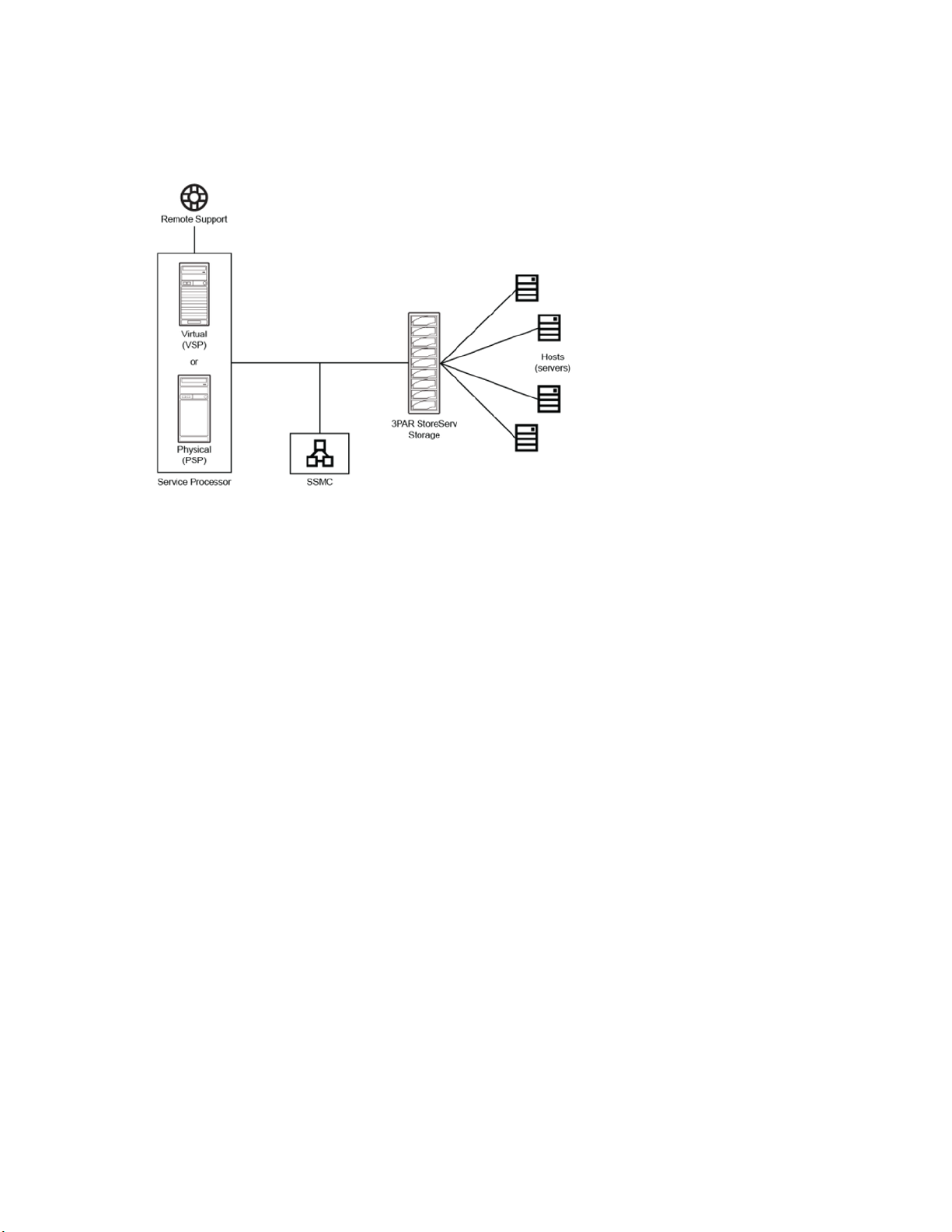
Figure 1: Architecture of the storage system
HPE 3PAR StoreServ 9000 Storage system:
The HPE 3PAR StoreServ 9000 Storage is an enterprise-class flash array. The storage system is
made up of a Controller Node Enclosure (two or four Controller Nodes), SAS Adapters, Host
Adapters; 2 to 48 Drive Enclosures with up to 24 small form factor (SFF) Solid-State Drives (SSDs)
each, and a Service Processor. The Controller Nodes include network ports to provide administrative
data-paths to the storage system.
Hosts (servers):
The host servers connect to the HPE 3PAR StoreServ 9000 Storage system directly or through a
switch with the following types of connections: FC, iSCSI, FCoE, or File Services.
HPE 3PAR StoreServ Management Console (SSMC) software:
The HPE 3PAR SSMC software defines, creates, and exports storage to your host servers. The HPE
3PAR SSMC also provides tools to monitor the health of your storage system.
HPE 3PAR Service Processor (SP) software:
Each HPE 3PAR StoreServ 9000 Storage system requires either an HPE 3PAR physical SP or HPE
3PAR virtual SP. The HPE 3PAR SP software is designed to provide remote monitoring, error
detection, error reporting, and support of diagnostic and maintenance activities involving the storage
system. The SP only sends support data to HPE 3PAR Remote Support. The HPE 3PAR virtual SP is
deployed as a virtual machine (VM) and runs on a customer-owned, customer-provided server and
communicates with the storage system over its Ethernet connection.
HPE 3PAR Remote Support connectivity:
HPE 3PAR Remote Support connectivity to HPE 3PAR Central is a utility that monitors the health of
your storage system. Information about the system health and configuration is transferred securely to
Hewlett Packard Enterprise. If HPE 3PAR Remote Support connectivity is enabled, it can also provide
critical software updates to your storage system.
8 About the HPE 3PAR StoreServ 9000 Storage system
Page 9

For additional HPE 3PAR StoreServ 9000 Storage architecture information, see the HPE 3PAR StoreServ
Storage Concepts Guide available at the Hewlett Packard Enterprise Information Library website:
www.hpe.com/info/storage/docs
For information about supported hardware and operating system (OS) platforms, see the Hewlett Packard
Enterprise Single Point of Connectivity Knowledge (SPOCK) website:
www.hpe.com/storage/spock
Installation media
Installation DVDs are not typically shipped with the HPE 3PAR StoreServ 9000 Storage system, and
instead the following delivery methods are used:
• If you selected the License to Use (LTU) delivery method of physical delivery during ordering,
installation media is shipped at the time of your order.
• If you selected electronic delivery, see the HPE e-Software Delivery Confirmation email for detailed
instructions for downloading the software. The e-Software Delivery Confirmation email was sent at the
time of purchase to your IT administrator, product manager, or purchasing agent.
If you require installation media, contact the Hewlett Packard Enterprise Support Center:
www.hpe.com/support/hpesc
Website for software downloads
Locate the software-receipt email that has the download link, or download the latest software from the
Hewlett Packard Enterprise Software updates and licensing website:
www.hpe.com/downloads/software
An HPE Passport profile and a valid Service Agreement ID (SAID) are required to access downloads.
Serial number location
The HPE 3PAR StoreServ 9000 Storage system has a 10-character serial number that is used with the
software setup.
The storage system serial number can be found in these locations:
• A label at the top-left-rear of the controller node enclosure
• The outside of the corrugated shipping material
Forum for the storage system
For the latest HPE 3PAR StoreServ 9000 Storage Customer Self Install (CSI) information, see the official
HPE 3PAR StoreServ Storage forum website in the Hewlett Packard Enterprise community:
www.hpe.com/forum/3PARCSIHELP
Use this forum to ask for help, share your installation experience, provide feedback, and search for
solutions to issues encountered during the installation process.
About the HPE 3PAR StoreServ 9000 Storage system 9
Page 10

Preparing: Process overview
Procedure
1. Review
2. Review Regulatory information on page 100.
3. Review Customer Self Install videos on page 11.
4. Complete the HPE 3PAR StoreServ 9000 Storage Software Set up Worksheet on page 95.
5. Review Acclimatizing on page 11.
6. Obtain the Tools for the installation on page 11.
7. Review Unpacking the factory-integrated-in-rack option: Process overview on page 12 and
complete the process.
Site planning on page 10.
Site planning
Successful installation of the HPE 3PAR StoreServ 9000 Storage system requires careful planning and
supervision and may require collaboration with authorized Hewlett Packard Enterprise representatives.
Proper site planning will help provide for a more efficient installation and greater reliability, availability, and
serviceability.
Environment—For optimal performance at a specific location, controlled environmental conditions are
recommended, and they can best be facilitated through raised flooring and under-floor air conditioning. It
is the responsibility of the customer to monitor this environment to ensure continued conformance with
the recommended environmental specifications.
Power—Adequate power is necessary for the reliable functioning of electronic equipment and for the
safety of the installation. The customer is responsible for procuring, installing, and maintaining adequate
power to the equipment.
• Provide suitable space for unpacking, installing, and operating the storage system.
• Review the power and the heating, ventilation, and air-conditioning (HVAC) requirements. Provide
adequate power facilities for the storage system and maintain proper environmental conditions for the
storage system. Order any additional support equipment indicated by the power and HVAC review.
• Verify that the electrical service wiring has been installed at the predetermined location before
installing the storage system. For detailed requirements, see the respective product specifications.
• Supply the network connections and external cabling required by the storage system.
• Ensure that all units in the specified configuration and all cables of the required length have been
ordered.
• Make a layout for the installation.
• Enable the appropriate HPE 3PAR Remote Support strategy.
10 Preparing: Process overview
Page 11
Procedure
Review the specific information concerning server-room environments and for input electrical power and
grounding requirements in the HPE 3PAR StoreServ 9000 Storage Site Planning Manual available at the
Hewlett Packard Enterprise Information Library website: www.hpe.com/info/storage/docs
Customer Self Install videos
The HPE 3PAR StoreServ 9000 Storage Customer Self Install (CSI) videos are available at the HPE
3PAR StoreServ 9000 Storage Customer Self Install Video website:
www.hpe.com/support/3PAR9000CSIVideo
NOTE: The video may take a minute to load.
Acclimatizing
CAUTION: To prevent potential damage to storage system hardware, do not power on the storage
system until it is fully acclimatized. The maximum acceptable rate of temperature change for a
nonoperating storage system is 36° F/hour (20° C/hour). If the storage system or its components
have experienced environmental changes during transit, allow enough time for the storage system
to acclimatize before proceeding with the power-on sequence.
Before powering on the HPE 3PAR StoreServ 9000 Storage system, the storage system might require up
to 24 hours to acclimatize to the new operating environment when outside-to-inside conditions vary
significantly.
Procedure
If condensation is present even after the 24-hour acclimatization period, wait for all condensation to fully
evaporate before completing the power-on sequence.
Tools for the installation
Table 1: Tools for the installation
Purpose Tools
Safety
Rack unpacking
Physical Service
Processor (SP)
connection setup
• ESD mat
• ESD grounding strap
• Scissors or snips
• Box cutter
• Socket wrench with 13 mm (1/2 in) and 17 mm (11/16 in) sockets for
removing L-bracket shipping clamps
• Adjustable wrench for leveling feet on the rack
Laptop for configuration of a physical Service Processor
Preparing: Process overview 11
Page 12

Unpacking the factory-integrated-in-rack option: Process overview
Prerequisites
Review the information about the placement of the HPE 3PAR StoreServ 9000 Storage system and
reserving room for service access in the HPE 3PAR StoreServ 9000 Storage Site Planning Manual
available at the Hewlett Packard Enterprise Information Library website:
www.hpe.com/info/storage/docs
Procedure
1. Complete Unpacking the HPE rack factory-integrated with the storage system on page 12.
2. Complete Positioning and stabilizing the HPE rack on page 20.
3. Drives are installed at the factory. However, if additional drives were received and not installed,
complete: Installing the drives: Process overview on page 21.
4. Review
complete the process.
Cabling the factory-integrated-in-rack option: Process overview on page 24 and
Unpacking the HPE rack factory-integrated with the storage system
During this procedure, refer to the unpacking diagrams on the outside of the cardboard shipping
container.
For more information about placement of the HPE 3PAR StoreServ Storage system and reserving room
for service access, see the HPE 3PAR StoreServ 9000 Storage Site Planning Manual available at the
Hewlett Packard Enterprise Information Library website:
www.hpe.com/info/storage/docs
NOTE: The illustrations in this procedure are examples and might not be an exact representation of your
HPE rack (cabinet).
12 Unpacking the factory-integrated-in-rack option: Process overview
Page 13
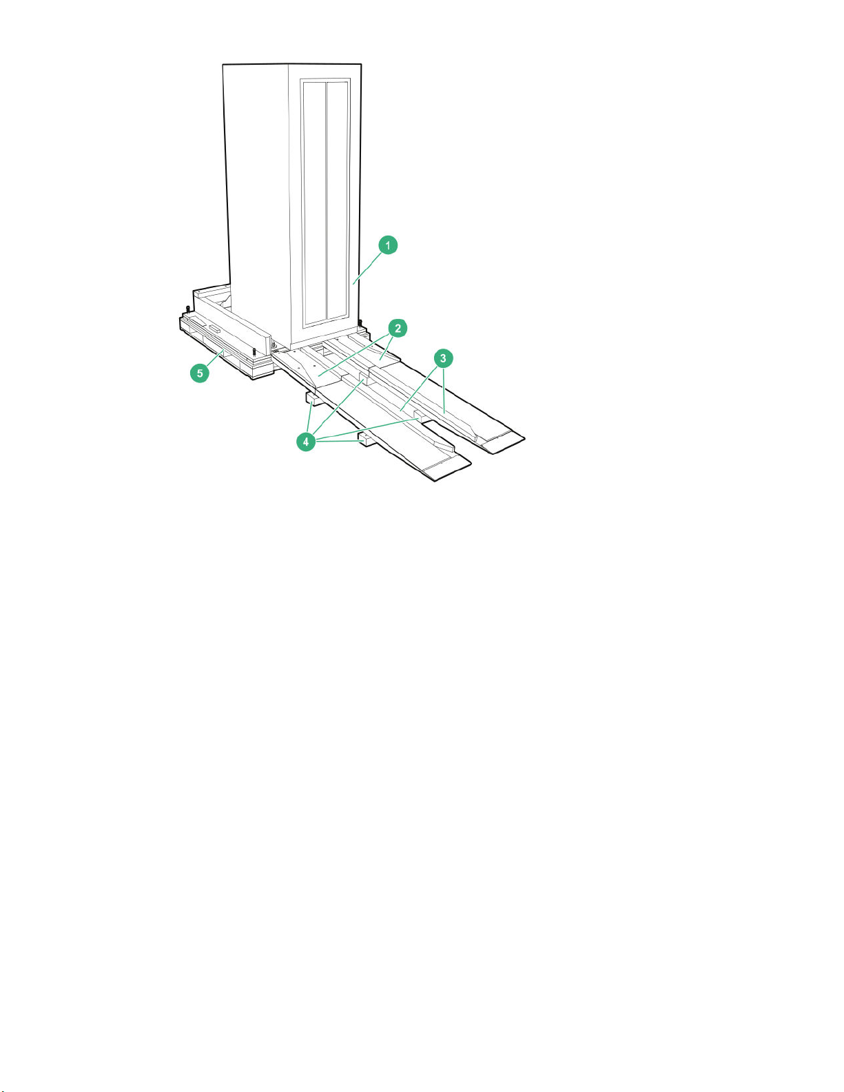
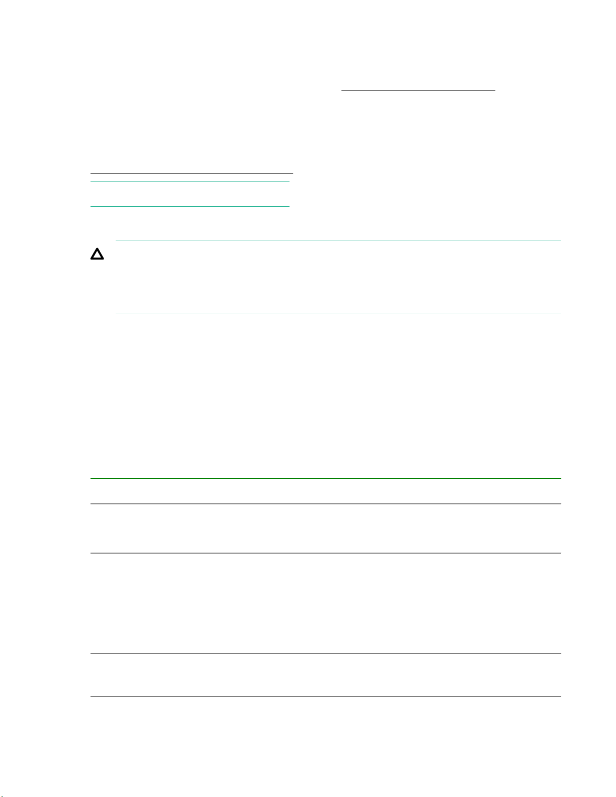
Figure 2: Items for unpacking an HPE rack
1. Rack (cabinet)
2. Ramps
3. Caster guides
4. Ramp supports
5. Pallet
Unpacking the factory-integrated-in-rack option: Process overview 13
Page 14
Prerequisites
CAUTION: Ensure that precautions have been taken to ensure rack stability and safety. Observe all
cautions and warnings included in the installation instructions.
• When the equipment arrives, verify that there is enough space to unload and unpack the HPE
3PAR StoreServ Storage system. The specific amount of space for unpacking the storage
system is based on the dimensions of the container, ramp, and room. This space is required to
access the storage system so that it can be removed from the crate and moved to its final
location.
• Verify that the delivered shipment matches the order by referring to the packing slip and SKUs.
• Observe local occupational safety requirements and guidelines for heavy equipment handling.
• Verify that the total weight of the rack is within the floor loading limit.
• Due to the weight of the rack, use extreme caution when unpacking and moving the rack to avoid
tipping the rack.
• When unloading the rack from the pallet, always use at least three people and do not stand in
front of the rack.
• To make the rack bottom-heavy and more stable, always load the heaviest item first from the
bottom of the rack and up.
Procedure
1. Inspect the packaging for damage and report any issues to the Hewlett Packard Enterprise Support
Center.
2. From the cardboard shipping container, remove the banding and top cover.
Figure 3: Removing the banding, HPE rack shipping container
14 Unpacking the factory-integrated-in-rack option: Process overview
Page 15
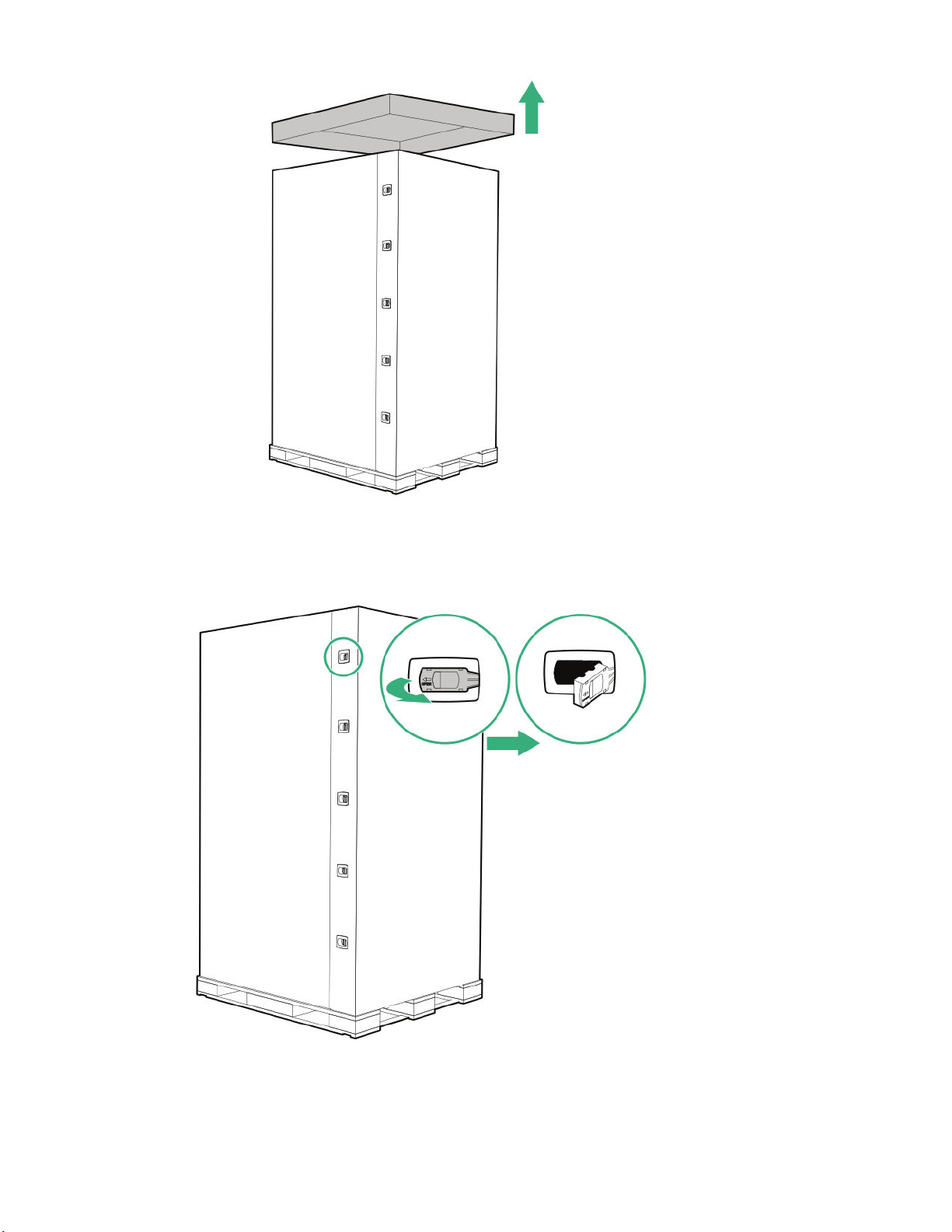
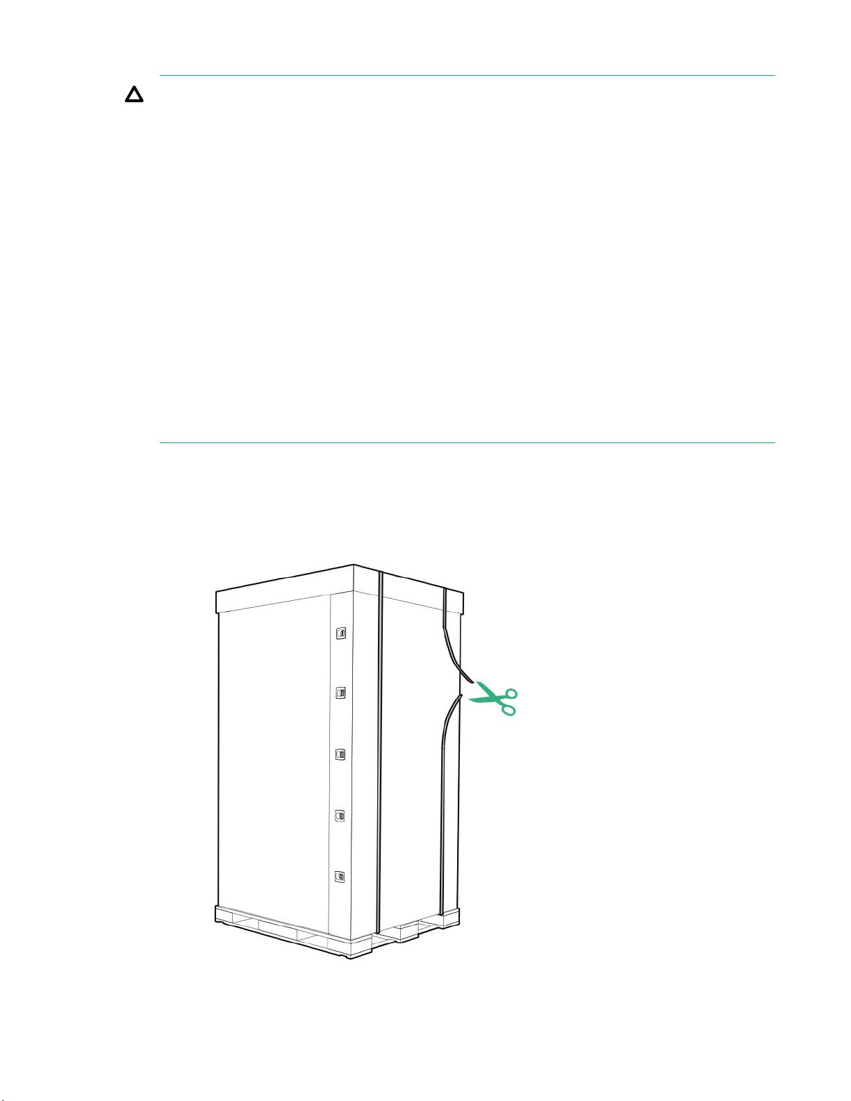
Figure 4: Removing the top, HPE rack shipping container
3. Remove the clips along the corrugated fiber board (CFB) walls and separate the CFB walls. Place the
separated walls away from the storage system.
Figure 5: Removing the clips, HPE rack shipping container
Unpacking the factory-integrated-in-rack option: Process overview 15
Page 16
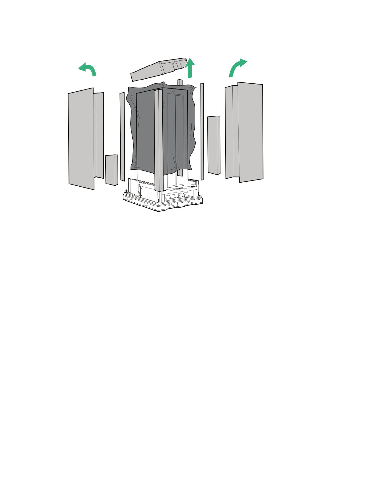
4. Remove the packing material (wrapping material, foam pieces, plastic ESD cover), and then set aside
the boxes that hold the ramps and additional installation hardware.
Figure 6: Removing the packing material, HPE rack shipping container
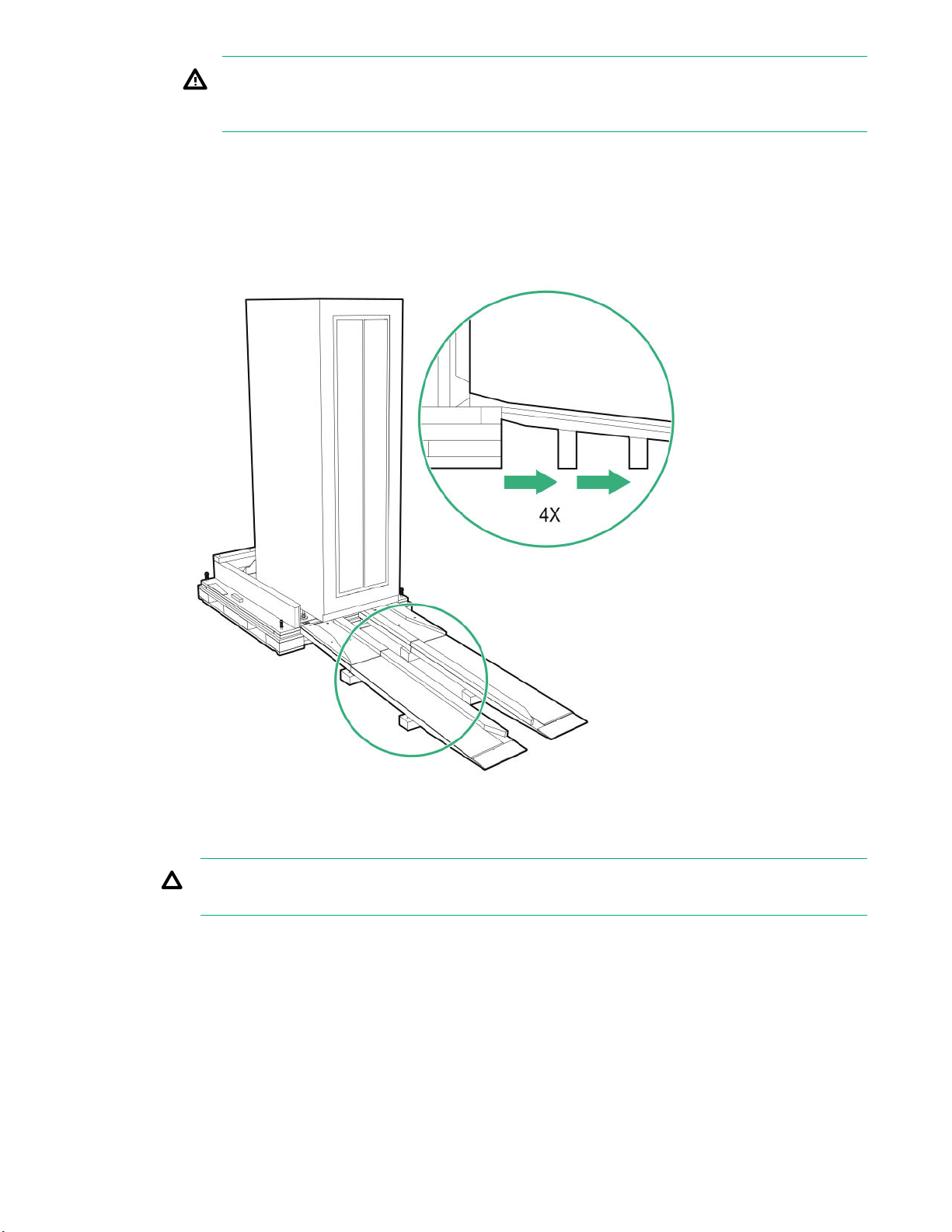
5. Remove the four shipping L-brackets that attach the rack to the pallet using a socket wrench with 13
mm (1/2 in) and 17 mm (11/16 in) sockets.
a. Starting at the rack front, open the door and locate the two L-brackets.
b. Remove the two 13 mm (1/2 in) bolts that secure the L-bracket to the rack.
c. Remove the two 17 mm (11/16 in) bolts that secure the L-brackets to the pallet.
d. At the rack rear, repeat this same procedure to remove the remaining two L-brackets.
6. Check that the leveling bolts are raised to provide sufficient clearance for removing the rack from the
pallet.
a. If it is necessary to raise a leveling bolt, use an adjustable wrench and turn the upper locking nut
clockwise to loosen.
16 Unpacking the factory-integrated-in-rack option: Process overview
Page 17
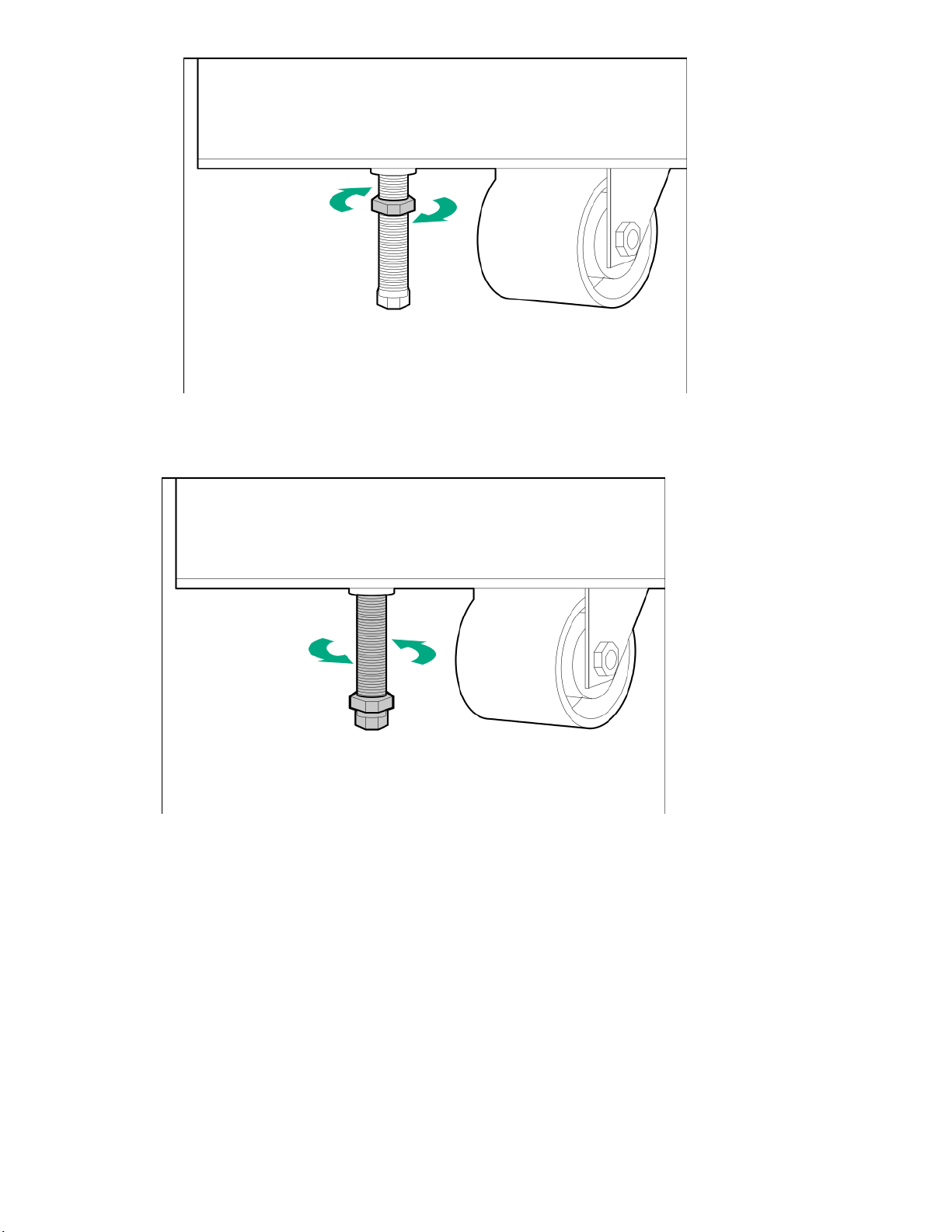
Figure 7: Releasing the locking nut, HPE rack leveling bolt
b. With an adjustable wrench, turn the leveling bolt counterclockwise until fully raised.
Figure 8: Raising the leveling bolt, HPE rack
7. Close and secure the rack front and rear doors.
8. Unpack the Ramp Assembly Kit and install the ramps and ramp supports at the front of the pallet.
a. Unpack the two ramps and four wooden supports.
b. Extend the ramps to their full length.
Unpacking the factory-integrated-in-rack option: Process overview 17
Page 18
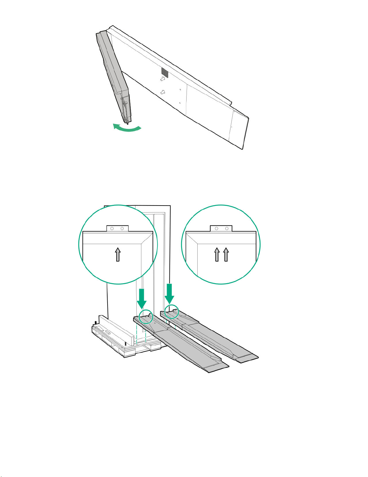
Figure 9: Extending the ramps, HPE rack shipping container
c. To install the ramps, match up the single arrow and double arrows on the pallet and ramps. The left
ramp has the single arrow, and the right ramp has double arrows. Attach the metal brackets with
the mounting holes along the front edge of the pallet, and then step firmly on the ramp and ensure
that the ramp is secure to the pallet.
Figure 10: Installing the ramps onto the pallet, HPE rack shipping container
18 Unpacking the factory-integrated-in-rack option: Process overview
Page 19
WARNING: Before rolling the rack from the pallet to the floor, correctly install the ramp
supports underneath the ramps, which will prevent the ramps from collapsing or causing the
rack to tip as it is moved down the ramps.
d. Attach the wooden ramp supports designated A and B to the locations on the ramps designated A
and B. Ensure that the angle of the wooden ramp support is attached to the ramps at the same
angle. The letters are marked on the ramp inside edge and support edge. Install support A beneath
the general area marked A on the rack, and do the same for support B. Insert the ramp support
beneath the ramp where the bottom of the ramp support touches the ground and the velcro on the
top of the ramp support is secure to the velcro underneath the ramp. The wooden ramp supports
must fit snugly between the ramp and the floor.
Figure 11: Installing the ramp supports, HPE rack shipping container
9. Roll the rack from the pallet to the floor.
CAUTION: When unloading the rack from the pallet, always use at least three people and do not
stand in front of the rack.
To roll the rack off the pallet to the floor, each person must grasp the rack corners with two people
guiding the rack down the ramp while a third person slowly pushes the rack from behind. Based on the
weight of the rack, it may be necessary to have both people on the side carefully push the rack until it
is completely on the ramp and adjust to guiding the rack the rest of the way down the ramps and onto
the floor.
Unpacking the factory-integrated-in-rack option: Process overview 19
Page 20
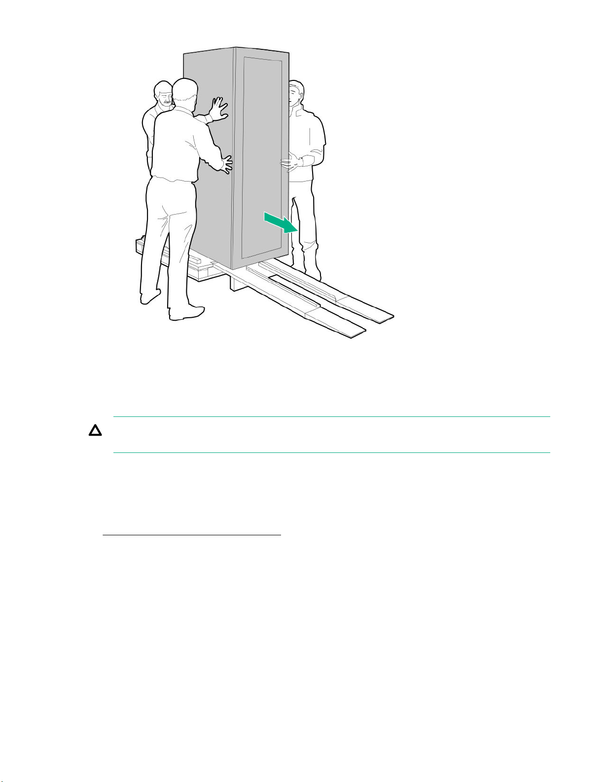
Figure 12: Unloading the HPE rack from the pallet
Positioning and stabilizing the HPE rack
CAUTION: To prevent potential damage to the storage system equipment, do not adjust the position
of the HPE rack when the power is on.
Prerequisites
• Read and complete all the configuration specifications and installation requirements in the HPE 3PAR
StoreServ 9000 Storage Site Planning Manual available at the Hewlett Packard Enterprise Information
Library website:
http://www.hpe.com/info/storage/docs
• Obtain an adjustable wrench for leveling the feet on the HPE rack.
Procedure
1. Roll the HPE rack to the final operating location. If the operating location has raised floor tiles with
cutouts to facilitate cable routing, position the rack over the cutouts in the tiles.
2. Stabilize and level the HPE rack.
After properly positioning the storage system, four leveling pads must be installed underneath the four
leveling bolts to stabilize the HPE rack and prevent movement during operation. The leveling pads are
normally located in a plastic bag in the box that contains rack keys and accessory material. The
leveling pads provide a wider base for supporting the rack and protecting the floor.
20 Unpacking the factory-integrated-in-rack option: Process overview
Page 21
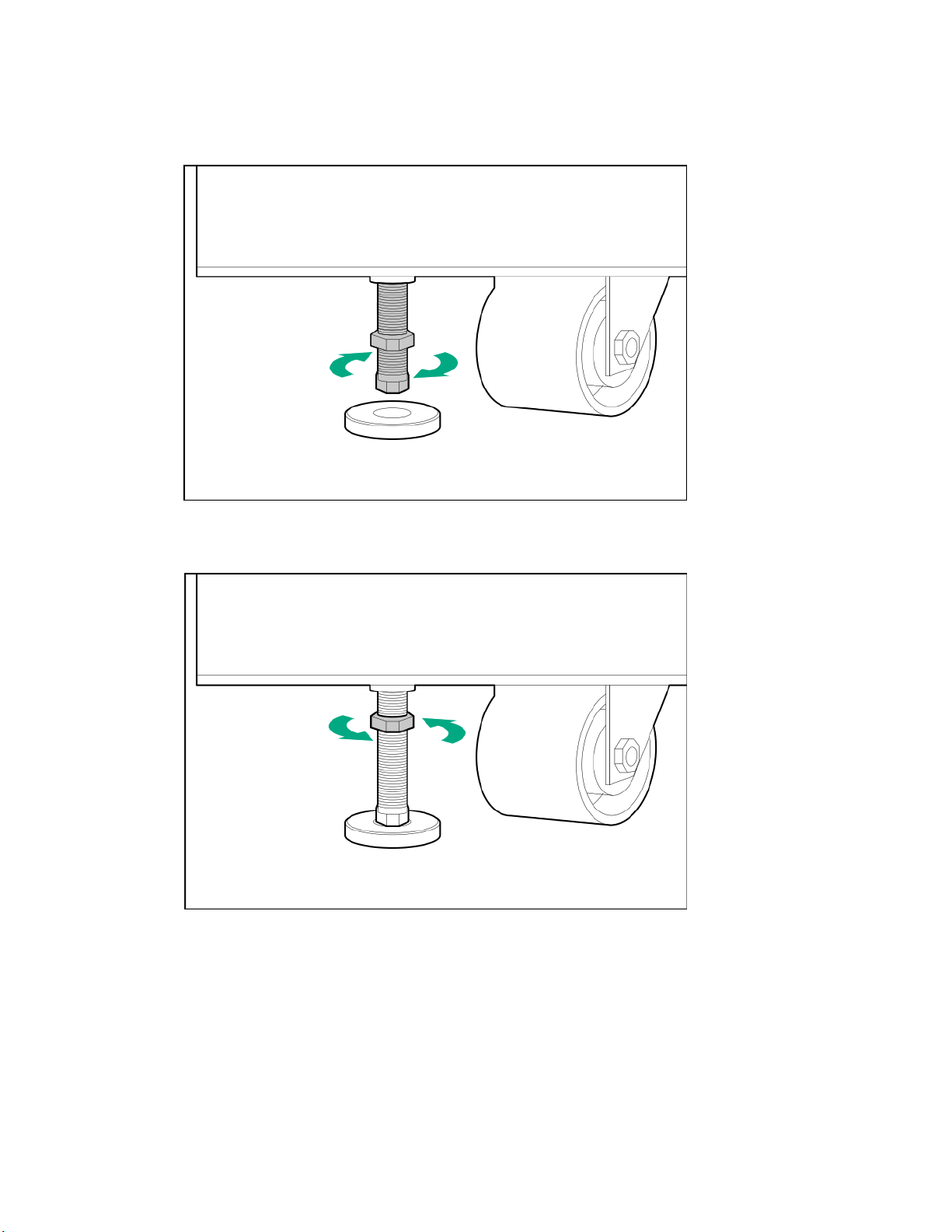
a. Position a leveling pad underneath the leveling bolt.
b. Using an adjustable wrench, turn the leveling bolt clockwise to extend the bolt until the entire
weight of the rack rests on the leveling pad instead of the caster. The caster must be slightly off the
floor, so it can swivel slightly by hand.
Figure 13: Lowering an HPE rack leveling bolt
c. Lock the leveling pad in place by turning the locking nut counterclockwise until tight.
Figure 14: Tightening the locking nut on an HPE rack leveling bolt
d. Repeat for each leveling pad.
Installing the drives: Process overview
This process overview is for installing the drives.
If it is necessary to install additional drives, complete the following process:
Unpacking the factory-integrated-in-rack option: Process overview 21
Page 22
Procedure
1. Review Guidelines for the drive installation on page 22.
2. Complete Installing the SFF drives on page 23.
Guidelines for the drive installation
IMPORTANT: The guidelines for how the drives are installed, allocated, and balanced are critical to
the performance and reliability of your storage system.
CAUTION:
• To ensure proper thermal control, slot-filler blanks are provided with the enclosures and must be
inserted in all unused drive bays in the enclosure. Operate the enclosure only when all drive
bays are populated with either a drive or a blank.
• If the storage system is enabled with the Data-at-Rest (DAR) encryption feature, only use
Federal Information Processing Standard (FIPS) capable encrypted drives.
• Before installing drives into enclosures, make sure that the enclosures are free of obstructions
(such as loose screws, hardware, or debris). Inspect the drives before installing them in the
enclosure to make sure that they are not damaged.
• To avoid errors when powering on the storage system, all enclosures must have at least one pair
of identical drives installed by following the guidelines for installing, allocating, and balancing
drives.
• A pair or pairs of drives must be installed in consecutively numbered slots in a drive enclosure and
must be of the same capacity and speed.
• The recommended initial quantity is eight SSDs per controller node pair, with a required minimum of
six SSDs per controller node pair.
• With a four-node configuration, the best practice is to attach the same number of drives to each
controller node pair.
• All drive enclosures must contain an even number of drives, with a minimum of two.
• Try to distribute an equal number of drives in all drive enclosures. If an equal distribution is not
possible, get as close as possible while still following the guidelines for the drives.
• RAID 6 is strongly recommended for all drive types.
SFF drive loading guidelines and examples:
The small form factor (SFF) drives are loaded starting at bay 0, left to right, leaving no empty space
between drives. The bays are numbered 0 through 23.
NOTE: The top right bay in the SFF drive enclosure must not be used and is populated with a blank
panel.
22 Unpacking the factory-integrated-in-rack option: Process overview
Page 23
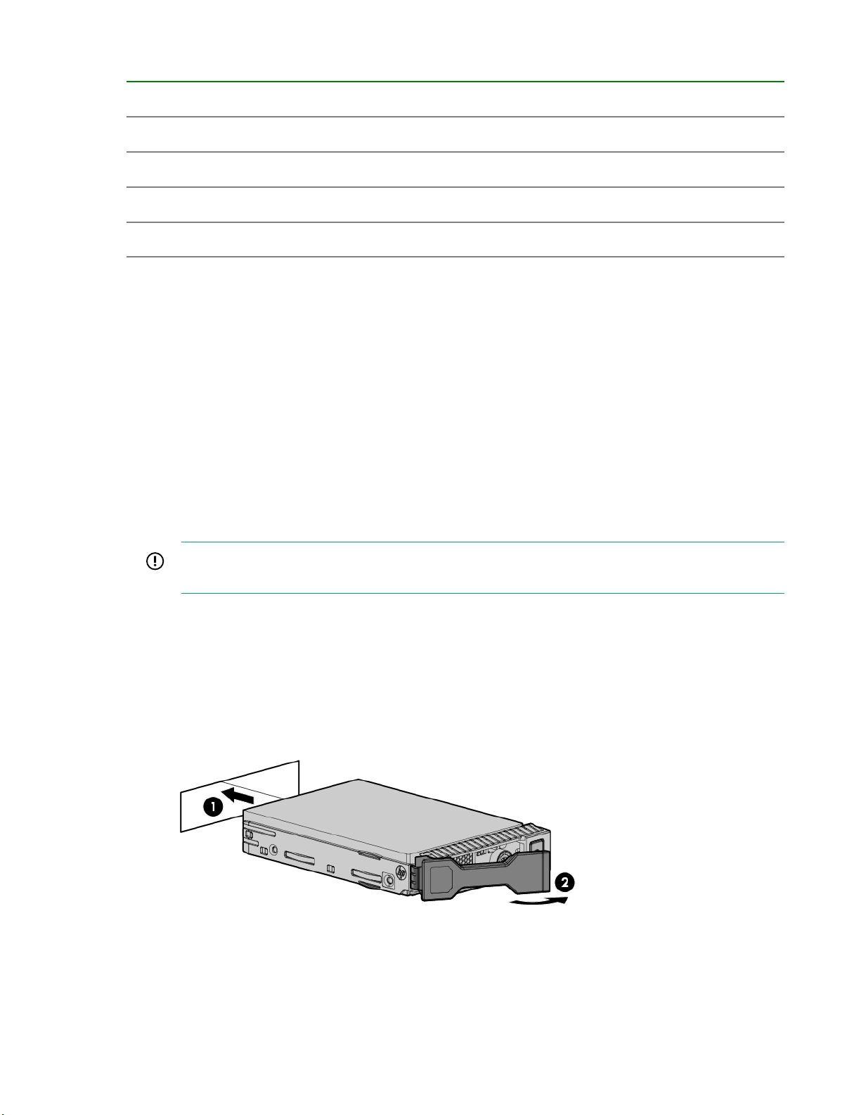
Table 2: Example slot order, SFF drive enclosure
20 (...) 21 (...) 22 (...) 23 (...) 24 (Do not use)
15 (...) 16 (...) 17 (...) 18 (...) 19 (...)
10 (...) 11 (...) 12 (...) 13 (...) 14 (...)
5 (SSD) 6 (SSD) 7 (SSD) 8 (...) 9 (...)
0 (SSD) 1 (SSD) 2 (SSD) 3 (SSD) 4 (SSD)
Installing the SFF drives
Prerequisites
• Determine an installation plan for allocating and loading the drives based on the provided guidelines,
number of drives, and drive types to install.
• To avoid damaging any circuitry, wear an ESD grounding strap.
• Prepare a surface with an ESD safe mat for staging components for installation.
Procedure
1. Unpack the component and place on an ESD safe mat.
2. Remove the slot-filler blanks from where you will be installing the pairs of drives.
IMPORTANT: For proper airflow and cooling, a slot-filler blank must remain installed in all
unused drive bays.
3. Install the pair or pairs of drives.
a. On the drive, press the release button to open the handle.
b. With the latch handle of the drive fully extended, align and slide the drive into the bay until the
handle begins to engage (1).
c. To seat the drive into the drive bay, close the handle (2).
Figure 15: Installing an SFF drive
Unpacking the factory-integrated-in-rack option: Process overview 23
Page 24

Cabling the factory-integrated-in-rack option: Process overview
IMPORTANT: Do not turn on power to the components at this time. Connect the power cables and
keep the power off until you power on the components.
IMPORTANT: To enable access to components for servicing, neatly route and secure the cables
along the sides of the rack.
For an HPE 3PAR StoreServ 9000 Storage system that is factory integrated in an HPE rack, the internal
cabling for the data cables and power cables has been completed before shipment; however, you must
complete the following additional cabling process:
Procedure
1. Review Guidelines for cabling on page 24.
2. Review
3. Complete Cabling the physical service processor (if installed) on page 27.
4. Complete Cabling the controller nodes: Process overview on page 28.
5. Complete Cabling the power cords of the power distribution units to the power receptacles at
the operating site on page 32.
6. Review Powering on: Process overview on page 33 and complete the process.
Guidelines for redundant power cabling on page 26.
Guidelines for cabling
Guidelines for the minimum bend radius of the cable
Bend radius is defined as the minimum radius to which the cable may safely be bent during installation
without the risk of permanent damage resulting in excessive attenuation or even breakage.
Use the manufacturer guidelines for the minimum bend radius of a cable. If manufacturer guidelines have
not been provided, use the general guidelines provided in the following table.
CAUTION: Bending optical cables tightly can damage the internal fibers, causing signal loss,
reduced reliability, and performance problems.
IMPORTANT: Minimum bend radius is not the same as minimum bend diameter.
Table 3: General minimum bend radius by cable type
Cable type Minimum bend radius
Standard power cable 1 in (2.5 cm)
Active optical cable (AOC) 2 in (5.08 cm)
Fiber optical cable 1.75 in (4.44 cm)
24 Cabling the factory-integrated-in-rack option: Process overview
Table Continued
Page 25

Cable type Minimum bend radius
Network Cat 5/6 (Unshielded) 1.75 in (4.44 cm)
Network Cat 5/6 (Shielded) 3.5 in (8.90 cm)
Coaxial (50W) 1.2 in (3 cm)
Coaxial (75W) 1.7 in (4.31 cm)
R1 InfiniBand - at connector 4.6 in (11.68 cm)
R2 InfiniBand - away from connector 2.6 in (6.60 cm)
• Power cable: Minimum bend radius prevents disconnection from power socket and possible arcing
under high-voltage conditions. When there is a high voltage or high current on the cable, sharp edges
or turns can cause puncturing of the cable jacket or arcing to equipment at local potential.
• Copper cable: Too sharp a radius will stress the center conductor, and may cause the cable outer
conductor to collapse or buckle. A sharp radius will cause impedance discontinuities at the bends
resulting in reflections and leads to signal degradation and circuit problems. An excessive bending of
cable can affect the geometry of the twists and increase the sensitivity to external noise and cause
stress on cable terminations.
• Fiber optic: Tighter bends may cause micro-bending of individual fibers that allow light to escape the
signal path, resulting in signal attenuation. More severe bends can break fiber strands completely,
resulting in signal loss.
General guidelines for cabling
• If not already applied by the factory, label all cables.
• Use the shortest possible cable between devices. Shorter cables reduce the possibility of signal
degradation over longer distances and are easier to route along the rear of the rack.
• Cables cannot have any obvious kinks, deformation, or damage to the connector housing or
sheathing. To prevent these issues, use extra care when unpacking, unwinding, routing, and storing
cables.
• To prevent mechanical damage or depositing contaminants from your hands, do not touch the ends of
the cable connectors.
• Before connecting a cable to a port, lay the cable in place to verify the length of the cable.
• Some data cables are prebent. Do not unbend or manipulate the cables.
• For components that must be movable while powered on, ensure that a full range of motion (frequently
called a service loop) is possible without cable interference or disconnection.
• Leave some slack in the cable (service loop). The slack provides room to remove and replace
components, allows for minor, inadvertent movement of the rack, and helps prevent the cables from
being bent to less than the minimum bend radius. The slack can be addressed by forming loops or
using a take-up spool as long as the minimum bend radius is maintained.
Guidelines for connecting, routing, and restraining cables
• When routing cables, always be sure that the cables are not in a position where they can be pinched
or crimped.
• When routing cables onto a management arm, secure the cables enough to prevent interference or
pinch areas during movement, yet not so tight as to cause binding.
Cabling the factory-integrated-in-rack option: Process overview 25
Page 26
• Restrain and support cables in a manner that eliminates stress on connectors and eliminates tight
bends of the cables.
• Secure fiber and AOC cables with loose fitting Velcro straps, instead of wire or cable ties.
• For cable ties, ensure that the cables are not compressed when cinching the tie, and cut the cable ties
flush with the cable tie head to prevent scratches or cuts during future service interactions.
• When the cables are restrained together, verify that storage system components and LED indicators
are easily visible and accessible for operation and maintenance.
Guidelines for disconnecting cables
To prevent damage to the internal wires of the cable or the port pins, operate the release latch on the
cable connector, and then grip the body of the cable connector to disconnect the cable instead of pulling
on the cable.
Guidelines for redundant power cabling
Power should be supplied to each component of the storage system using redundant power supplies and
redundant power distribution units (PDUs). If the power connections for the system are correctly
configured for power redundancy, the system will stay operational if a power failure occurs with an input
power source, a PDU, or a power supply.
WARNING: To avoid possible injury, damage to storage system equipment, and potential loss of
data, do not use the surplus PDU outlets. Never use PDU outlets to power components that do not
belong to the storage system or that reside in other racks.
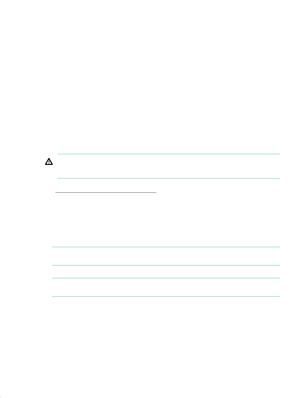
To achieve redundant power, the storage system must have the following redundant power configuration.
See Figure 16: Redundant power configuration on page 27.
• Customer power source: Each main, independent, grounded-electrical power source should be
controlled and protected by its own circuit breaker.
• PDU:
◦ The even-numbered PDUs should be connected to customer power source (A)
◦ The odd-numbered PDUs should be connected to customer power source (B).
NOTE: The number of PDUs in a rack can vary depending on the rack and power type (such as,
single- or three-phase power).
• Power supply:
NOTE: The generic term "power supply" refers to various types of power components, such as a
power supply unit (PSU), power cooling module (PCM), or a power cooling battery module (PCBM).
◦ Controller node pair: Each power supply should be connected to a separate PDU.
◦ Drive enclosure: Each power supply should be connected to a separate PDU.
◦ Even-numbered power supplies: Each power supply 0 should be connected to an even-
numbered PDU using a black power cable.
◦ Odd-numbered power supplies: Each power supply 1 should be connected to an odd-numbered
PDU using a gray power cable.
26 Cabling the factory-integrated-in-rack option: Process overview
Page 27
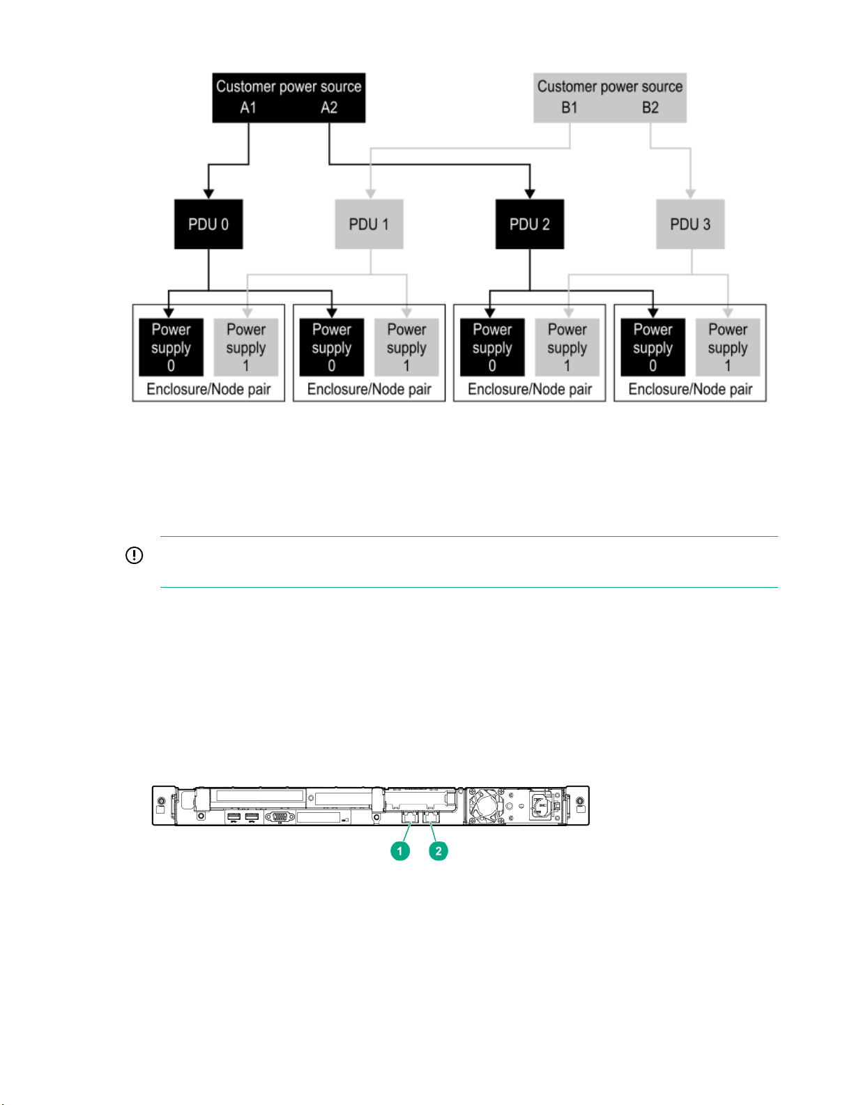
Figure 16: Redundant power configuration
Cabling the physical service processor (if installed)
The physical service processor is an optional component that can be used with the HPE 3PAR StoreServ
9000 Storage system instead of using a virtual service processor.
IMPORTANT: Do not turn on power to the components at this time. Connect the power cables and
keep the power off until you power on the components.
Procedure
1. Connect the cable for the management connection.
a. Connect an Ethernet cable between the Management port and the network using the same subnet
as the storage system.
b. At the rack rear, neatly route and secure the cables along the right side of the rack.
Figure 17: Physical service processor ports, HPE ProLiant DL120 Gen9 Server
Cabling the factory-integrated-in-rack option: Process overview 27
Page 28
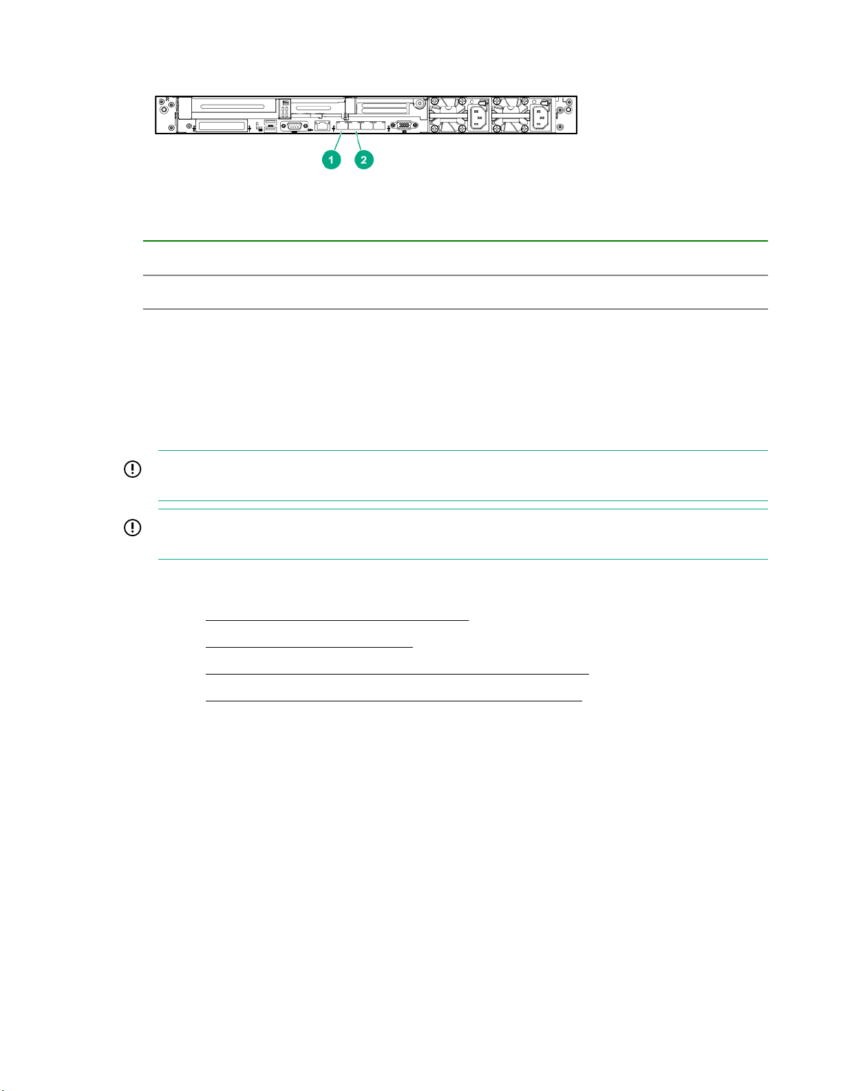
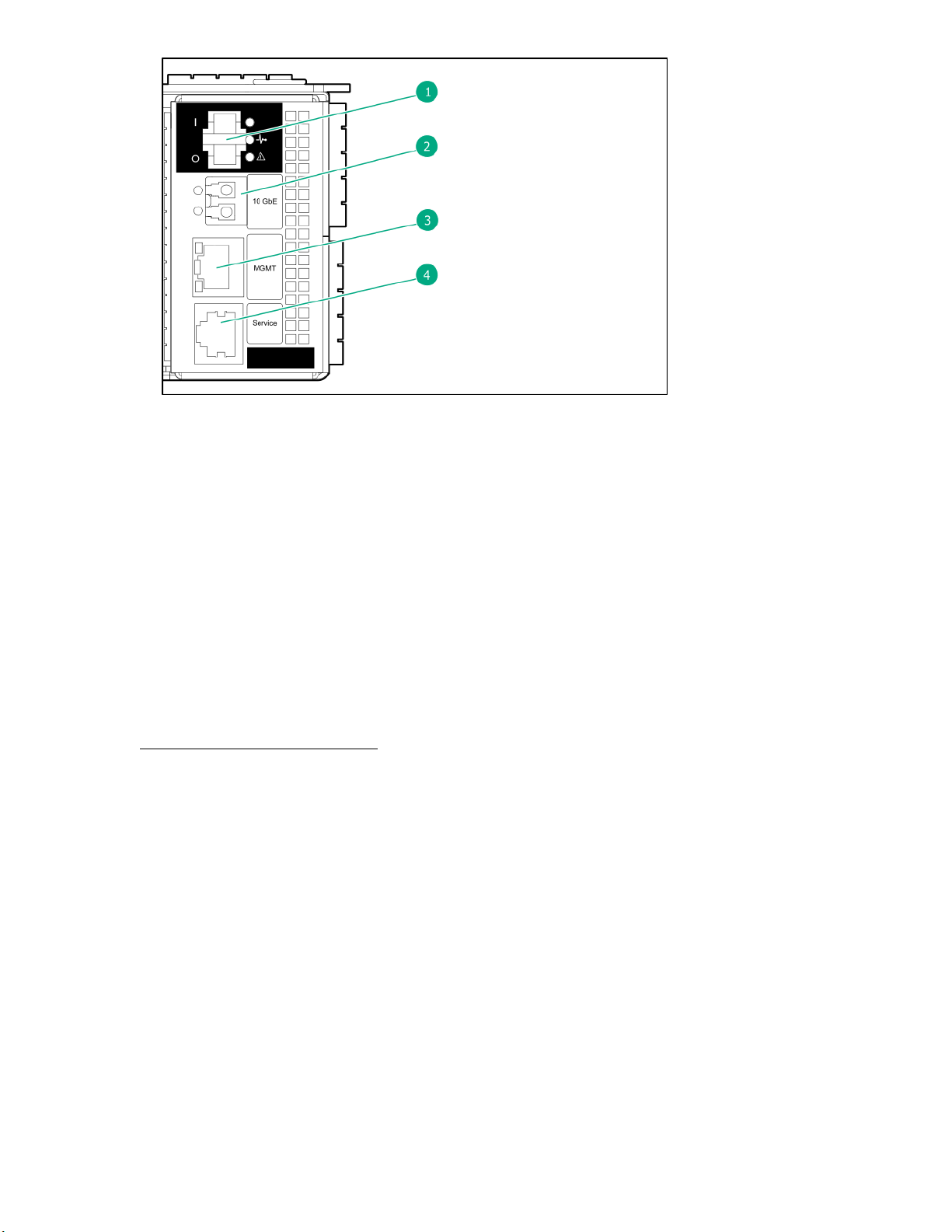
Figure 18: Physical service processor ports, HPE ProLiant DL360 Gen10 Server
1 Management (MGMT) port; NIC 1
2 Service port; NIC 2
2. Connect and secure the cable for the power connection.
Power connection—Connect a power cable to a power source, but do not turn on the power yet.
For dual power supplies, connect power cables to both power supplies and each to an independent
power source.
Cabling the controller nodes: Process overview
IMPORTANT: Do not turn on power to the components at this time. Connect the power cables and
keep the power off until you power on the components.
IMPORTANT: To enable access to components for servicing, neatly route and secure the cables
along the sides of the rack.
Procedure
1. Complete Cabling for the management connection on page 28.
2. Complete Cabling for the host connection on page 29.
3. Complete Cabling for the Remote Copy connection (optional feature) on page 31.
4. Complete Cabling for the File Persona connection (optional feature) on page 31.
Cabling for the management connection
Procedure
• Connect a CAT-5e or Cat 6 Ethernet cable between the onboard MGMT port on each controller node
and the network. At the rack rear, neatly route and secure the cables along the right side of the rack.
Each controller node supports one Ethernet connection to a switch or hub. Separate connections from
the Ethernet switch or hub to at least two controller nodes are required to support redundancy. One IP
address is shared between the two connections, and only one network connection is active at a time. If
the active network connection fails, the IP address is automatically moved to the surviving network
connection.
28 Cabling the factory-integrated-in-rack option: Process overview
Page 29
1. Power switch
2. 10 GbE port (RCIP)
3. 1 GbE Management (MGMT) port
4. Service port (Console)
Figure 19: Controller node ports
Cabling for the host connection
Prerequisites
Before connecting any FC or iSCSI cables, follow the guidelines provided for your host OS that are
available in an HPE 3PAR host-OS implementation guide available at the Hewlett Packard Enterprise
Information Library website:
www.hpe.com/info/storage/docs
For instance, the following are some of the available HPE 3PAR host-OS implementation guides:
• HPE 3PAR AIX and IBM Virtual I/O Server Implementation Guide
• HPE 3PAR Apple OS X Implementation Guide
• HPE 3PAR Citrix XenServer Implementation Guide
• HPE 3PAR HP-UX Implementation Guide
• HPE 3PAR Solaris Implementation Guide
• HPE 3PAR SUSE Linux Enterprise Implementation Guide
• HPE 3PAR Red Hat Enterprise Linux and Oracle Linux Implementation Guide
• HPE 3PAR VMware ESX/ESXi Implementation Guide
• HPE 3PAR Windows Server 2016/2012/2008 Implementation Guide
Cabling the factory-integrated-in-rack option: Process overview 29
Page 30

Procedure
• Connect a cable between a port on a host adapter (FC/iSCSI) and a switch or directly to the host; one
or more cables per controller node. Hewlett Packard Enterprise recommends connecting each host to
both controller nodes in a controller nodes pair (node pair: 0/1 or 2/3) using the same port number on
the FC/iSCSI host adapters to provide redundancy. At the rack rear, neatly route and secure the
cables along the left side of the rack. When possible, route and secure host cables towards the rear of
the rack, separated from the internally routed SAS cables.
Recommended configurations for FC/iSCSI host connectivity
For optimal redundancy and I/O load balancing, Hewlett Packard Enterprise recommends the
guidelines for connectivity from any given host-server (host) to the controller node pair (node pair) on
the storage system:
◦ Depending on the number of host ports available, balance the host-server ports across both
controller nodes in the node pair of the storage system at a minimum.
◦ From any given host, make a pair of connections from any given host to the same numbered slot
and port (partner port) on each controller node in the node pair.
◦ If more than one host connection can be made per controller node, distribute connections of the
same type (for example, FC) from any given host across host adapters in different slots (where
available) on any given controller node.
NOTE: To provide redundancy and to permit online software upgrades, both controller nodes in a node
pair (for example, controller nodes 0 and 1 or controller nodes 2 and 3) must maintain connections to
each host server.
Host connectivity using a switch
◦ For an Ethernet switch, the recommended configuration for the connection is from the Ethernet
switch or hub to two controller nodes (node pair).
◦ For an FC switch, you must set up FC fabric zoning to restrict WWNs seen by the system.
NOTE: With HPE 3PAR File Persona or HPE 3PAR Remote Copy, an additional Ethernet connection
is required.
See “Supported Network Topologies” in the HPE 3PAR StoreServ 9000 Storage Site Planning Manual
available at the Hewlett Packard Enterprise Information Library website:
www.hpe.com/info/storage/docs
30 Cabling the factory-integrated-in-rack option: Process overview
Page 31

FC cable limitations for host connectivity
Cable size Speed Maximum cable length limit
50 micron 16 Gb/s 50 meters
The maximum supported Fibre Channel cable length is based on the cable size and port speed.
Cabling for the Remote Copy connection (optional feature)
Hewlett Packard Enterprise
For the optional HPE 3PAR Remote Copy connection with the HPE 3PAR StoreServ 9000 Storage, see
the HPE 3PAR Remote Copy Software User Guide available at the Hewlett Packard Enterprise
Information Library website:
www.hpe.com/info/storage/docs
Procedure
Connect a cable between the onboard 10 GbE (RCIP) port or four-port 16Gb FC HBA (RCFC) and
another HPE 3PAR StoreServ 9000 system. To provide redundancy, connect two or more controller
nodes per storage system.
Cabling for the File Persona connection (optional feature)
Hewlett Packard Enterprise
For the optional HPE 3PAR File Persona connection with the HPE 3PAR StoreServ 9000 Storage, see
the HPE 3PAR File Persona User Guide available at the Hewlett Packard Enterprise Information Library
website:
www.hpe.com/info/storage/docs
Cabling the factory-integrated-in-rack option: Process overview 31
Page 32

Procedure
Connect a cable between a port on a two-port 10Gb Ethernet NIC adapter and the network. To provide
redundancy, connect two or more controller nodes per storage system.
Cabling the power cords of the power distribution units to the power receptacles at the operating site
IMPORTANT: Do not turn on power to the components at this time. Connect the power cables and
keep the power off until you power on the components.
Each AC power cord on the PDUs must connect to an appropriate outlet based on the cord type and
power requirements for supplying power to the storage system.
Prerequisites
WARNING: Before connecting a main power cable, confirm that the circuit breakers for all internal
PDUs are set to the OFF position to prevent danger of electric shock and potential damage to
equipment.
IMPORTANT: Verify that the operating site provides redundant power.
Procedure
1. Based on the location of the power receptacles at the operating site, route the PDU power cords
through the top or bottom of the rack.
2. Connect the even-numbered PDUs to power receptacles from one power source (source A) and
connect the odd-numbered PDUs to power receptacles from another power source (source B) with
each power receptacle controlled and protected by its own circuit breaker.
32 Cabling the factory-integrated-in-rack option: Process overview
Page 33

Powering on: Process overview
Procedure
1. Review Precautions for powering on the storage system on page 33 .
2. Review Checking AC power cable connections on page 33 .
3. Complete Powering on the storage system on page 34 .
4. (Optional) Complete Checking enclosure power redundancy (optional) on page 35 .
5. Review Setting up the service processor connection: Process overview on page 37 and
complete the process.
Precautions for powering on the storage system
To reduce the risk of electric shock or damage to the equipment, follow these precautions.
CAUTION:
• Do not disable the power cable grounding plug. The grounding plug is an important safety
feature.
• Plug the power cable into a grounded (earthed) electrical outlet that is easily accessible at all
times.
• Do not route the power cable where it can be walked on or pinched by items placed against it.
Pay particular attention to the plug, electrical outlet, and the point where the cable extends from
the storage system.
• Verify that there is clear access to all components for servicing by tying all power cables to
restrain them behind the rack column.
• To avoid potential damage to equipment, do not adjust the positioning of the rack after powering
on the HPE 3PAR StoreServ Storage.
Checking AC power cable connections
A factory-integrated storage system arrives with all internal power cables configured and connected.
Procedure
1. Ensure that the alternating-current (AC) power cables are properly configured and connected to the
components.
2. Ensure that the cable locks and cable ties on the AC power cables are properly connected on the
power distribution units (PDUs) and power supplies.
3. Ensure that all of the power cables are properly secured with restraints.
Powering on: Process overview 33
Page 34

Powering on the storage system
Prerequisites
• The acclimatization process has completed for the storage system components. Do not power on the
storage system until it is fully acclimatized. Allow up to 24 hours, and if condensation is still present,
wait until fully evaporated before powering on. If small drops of water can be seen on any of the
surfaces, condensation is present.
• The storage system does not exceed the ratings of the power sources and adheres to the guidelines in
the HPE 3PAR StoreServ 9000 Storage Site Planning Manual available at the Hewlett Packard
Enterprise Information Library website:
www.hpe.com/info/storage/docs
• Drives or slot-filler blanks are in all bays for proper thermal control.
• If power connections are underneath the rack, route the PDU power cables under the bracket at the
bottom rear of the rack.
Procedure
1. On all PDUs, turn on the power by setting all circuit breakers to the ON position.
For a physical service processor (SP), the power starts automatically when the PDUs are powered on.
Alternatively, use the power reset button. For the drive enclosures, the power starts automatically,
because there is no power switch.
2. On each controller node, turn on the power by setting the power switch to the ON position.
Figure 20: Controller node power switch
3. Wait approximately 10 minutes for completion of the storage system power-on/boot sequence.
4. At the rear of the storage system, verify that all status LEDs are illuminated green. If any of the LEDs
are amber, troubleshoot the issue before continuing to power on. There is an LED status for the
controller nodes, drive enclosures, and power supply units.
34 Powering on: Process overview
Page 35

IMPORTANT: The Status LED at the storage system front is not illuminated green at this time.
Instead, after the power on sequence, the UID/Service LED is illuminated blue and the Fault LED
is illuminated amber. Later during the software Guided Setup, these LEDs turn off and the Status
LED becomes illuminated green.
Checking enclosure power redundancy (optional)
To verify that the storage system has been correctly configured to achieve power redundancy, complete
the following procedure:
CAUTION:
• Hewlett Packard Enterprise recommends checking for power redundancy before the system is
initialized. If the system is already initialized, checking the power redundancy could cause an
outage.
• To maintain power to the storage system during this procedure, only one power distribution unit
(PDU) should be powered off at a time.
NOTE: The generic term "power supply" refers to various types of power components, such as a power
supply unit (PSU), power cooling module (PCM), or a power cooling battery module (PCBM).
Prerequisites
Ensure that the power cabling for the storage system follows the guidelines for redundant power cabling.
See Guidelines for redundant power cabling on page 26.
Figure 21: Redundant power configuration
Powering on: Process overview 35
Page 36

Procedure
1. Ensure that all power supplies (power supply units) for the enclosures (controller node enclosure and
drive enclosure) have a solid-green status LED indicating a normal operation state.
• Review Power supply unit LEDs, controller node enclosure on page 82 .
• Review Power supply unit LEDs, drive enclosure on page 83 .
2. Turn off the power source at the panel that provides input power to one PDU. Alternatively, the circuit
breaker(s) on the PDU can be set to the OFF position.
For example, as represented in Figure 21: Redundant power configuration on page 35:
• When Customer power source A1 is turned off, the power supplies connected to PDU-0 turn off.
• When Customer power source B2 is turned off, the power supplies connected to PDU-3 turn off.
3. Ensure that the following expected behavior has occurred:
• Every enclosure: At least one power supply is operating normally.
• Every power supply without input power: The LEDs turn off.
4. After confirmation of the expected behavior, turn back on the power source at the panel for the PDU
and wait 30-60 seconds.
5. Before moving to the next PDU, ensure that the green status LED is illuminated on all components.
6. For each PDU, repeat the prior steps.
36 Powering on: Process overview
Page 37

Setting up the service processor connection: Process overview
For detailed service processor (SP) connection setup instructions, see the HPE 3PAR Service Console
and StoreServ Management Console Quick Setup Guide and HPE 3PAR Service Processor Software
User Guide available at the Hewlett Packard Enterprise Information Library website:
www.hpe.com/info/storage/docs
Procedure
1. Review About the service processor on page 37.
2. Ensure Network and firewall support access on page 38.
3. Based on your service processor, complete one of the following processes:
a. Setting up the physical service processor connection: Process overview on page 40
b. Setting up the virtual service processor connection with VMware ESXi: Process overview on
page 42
Setting up the virtual service processor connection with Hyper-V: Process overview on page
c.
44
4. Review Setting up the service processor and storage system software: Process overview on
page 46 and complete the process.
About the service processor
Each storage system requires a service processor (SP), which can be either physical or virtual. Both the
physical SP and the virtual SP provide remote monitoring and report storage system errors, and can
perform diagnostic and maintenance activities involving the storage system. With HPE 3PAR SP 5.x
software, only one standalone HPE 3PAR StoreServ 9000 Storage system can be added to the service
processor.
The preferred service processor setup method is to connect to the service processor using the
preconfigured, nonroutable IP address through a local network using a browser, which starts the HPE
3PAR Guided Setup automatically.
For service events performed by a service technician, the customer must provide the following to the
technician:
• For a physical SP, access to the physical SP for a direct connection to the Service port.
• For a virtual SP, access to their network and the IP address to the virtual SP.
For detailed information about the service processor, see the documents available at the Hewlett Packard
Enterprise Information Library website:
www.hpe.com/info/storage/docs
Service processor types
Physical SP
A physical SP is a dedicated service appliance located within the storage rack providing proximity to the
storage system. For access to the physical SP by an authorized service provider, a direct connection to
Setting up the service processor connection: Process overview 37
Page 38

the physical SP is required. If you choose a physical SP at the time of ordering, your storage system will
include a physical SP installed in the same rack as the controller nodes.
A physical SP has two physical network connections:
• The Management (MGMT) port requires a connection to the network to communicate with the storage
system.
• The Service port is for maintenance purposes only and is not connected to the network.
Virtual SP
A virtual SP is deployed as a virtual machine. For access to the virtual SP by an authorized service
provider, a network connection to the virtual SP is required. The virtual SP software is provided in an
Open Virtual Format (OVF) for VMware vSphere Hypervisor and self-extractable virtual hard disk (VHD)
package for Microsoft Hyper-V.
CAUTION: To ensure that the management of the storage system by the virtual SP is independent
of other host servers connected to the storage system, do not install the virtual SP software on a
host server that is also using storage from the storage system. The virtual SP must use the local
boot disk of the assigned VMware server and not boot from the storage system LUNs.
The HPE 3PAR Text-based User Interface
The HPE 3PAR Text-based User Interface (TUI) is a utility on the HPE 3PAR SP that enables limited
configuration and management of the SP and access to the HPE 3PAR CLI of an attached storage
system. The intent of the HPE 3PAR TUI is not to duplicate the functionality of the HPE 3PAR SP Service
Console interface, but to allow a way to fix problems that may prevent you from using the Service
Console interface.
The TUI appears when you log in to the Linux console opened from the VMware vSphere Client or
through a terminal emulator using SSH to a physical or virtual SP. Prior to SP initialization, you can log in
to the TUI with the user name admin and no password. To access the TUI after the SP has been
initialized, you will need to log in to the console with the admin user name and the password you created
during the initialization.
The SP ID and model are always displayed in the heading. Before the SP is initialized, the SP ID is
displayed as SP00000. After initialization, the actual ID assigned to the SP during initialization is
displayed.
Network and firewall support access
Before performing the service processor (SP) connection setup, ensure that there are no customer
firewall restrictions to the existing HP servers and the new HPE servers on port 443. Firewall and proxy
server configuration must be updated to enable outbound connections from the service processor to the
existing HP servers and the new HPE servers.
For a list of HP and HPE server host names and IP addresses, see Firewall and proxy server
configuration on page 38.
Firewall and proxy server configuration
Firewall and proxy server configuration must be updated on the customer network to enable outbound
connections from the service processor to the existing HP servers and the new HPE servers.
HP and HPE server host names and IP addresses
• HPE Remote Support Connectivity Collector Servers:
38 Setting up the service processor connection: Process overview
Page 39

◦ https://storage-support.glb.itcs.hpe.com (16.248.72.63)
◦ https://storage-support2.itcs.hpe.com (16.250.72.82)
• HPE Remote Support Connectivity Global Access Servers:
◦ https://c4t18808.itcs.hpe.com (16.249.3.18)
◦ https://c4t18809.itcs.hpe.com (16.249.3.14)
◦ https://c9t18806.itcs.hpe.com (16.251.3.82)
◦ https://c9t18807.itcs.hpe.com (16.251.4.224)
• HP Remote Support Connectivity Global Access Servers:
◦ https://g4t2481g.houston.hp.com (15.201.200.205)
◦ https://g4t2482g.houston.hp.com (15.201.200.206)
◦ https://g9t1615g.houston.hp.com (15.240.0.73)
◦ https://g9t1616g.houston.hp.com (15.240.0.74)
• HPE RDA Midway Servers:
◦ https://midway5v6.houston.hpe.com (2620:0:a13:100::105)
◦ https://midway6v6.houston.hpe.com (2620:0:a12:100::106)
◦ https://midway7v6.houston.hpe.com (2620:0:a13:100::108)
◦ https://midway9v6.houston.hpe.com (2620:0:a13:100::109)
◦ https://midway8v6.houston.hpe.com (2620:0:a12:100::109)
◦ https://g4t8660g.houston.hpe.com (15.241.136.80)
◦ https://s79t0166g.sgp.ext.hpe.com (15.211.158.65)
◦ https://s79t0165g.sgp.ext.hpe.com (15.211.158.66)
◦ https://g9t6659g.houston.hpe.com (15.241.48.100)
◦ https://g9t7157g.houston.hpe.com (15.241.48.251)
◦ https://g9t7158g.houston.hpe.com (15.241.48.252)
◦ https://g4t9581g.houston.hpe.com (15.241.136.208)
◦ https://s54t0109g.sdc.ext.hpe.com (15.203.174.94)
◦ https://s54t0108g.sdc.ext.hpe.com (15.203.174.95)
◦ https://s54t0107g.sdc.ext.hpe.com (15.203.174.96)
• HPE InfoSight Servers:
◦ https://sfrm-production-llb-austin1.itcs.hpe.com (16.252.64.51)
◦ https://sfrm-production-llb-houston9.itcs.hpe.com (16.250.64.99)
◦ https://infosight1.itcs.hpe.com (16.248.65.16)
Setting up the service processor connection: Process overview 39
Page 40

• For communication between the service processor and the HPE 3PAR StoreServ Storage system, the
customer network must allow access to the following ports on the storage system.
◦ Port 22 (SSH)
◦ Port 5781 (Event Monitor)
◦ Port 5783 (CLI)
• For communication between the browser and the service processor, the customer network must
enable access to port 8443 on the SP.
• For communication between the vCenter instance and the service processor, the customer network
must enable access to port 443 (default port) on the SP and vCenter server.
Setting up the physical service processor connection: Process overview
Procedure
Complete Assigning an IP address to the physical service processor with a functional network
using the Guided Setup—SP5.x on page 40.
Assigning an IP address to the physical service processor with a functional network using the Guided Setup—SP5.x
Prerequisites
• The physical service processor (SP) and the HPE 3PAR StoreServ Storage are connected to a
network with a gateway.
• The service processor must be on the same subnet as the HPE 3PAR StoreServ Storage system.
Procedure
1. Connect a service laptop to the physical service processor.
With an Ethernet cable, connect a private Ethernet switch/hub between an Ethernet port on a service
laptop and the service port on the physical service processor.
IMPORTANT: Hewlett Packard Enterprise recommends using a private Ethernet switch/hub for
connection between a service laptop and a physical service processor to ensure that the service
laptop does not lose its network connection during the procedure. The loss of a network
connection can result in a failure of the procedure. Any Ethernet switch/hub with four to eight
ports is supported, such as the HPE 1405-5G Switch (J97982A).
40 Setting up the service processor connection: Process overview
Page 41

Figure 22: Physical service processor ports, HPE ProLiant DL120 Gen9 Server
Figure 23: Physical service processor ports, HPE ProLiant DL360 Gen10 Server
1 Management (MGMT) port; NIC 1
2 Service port; NIC 2
2. Temporarily configure the LAN connection of the service laptop as follows:
IP Address: 10.255.155.49
Subnet mask: 255.255.255.248
3. To begin the HPE 3PAR Guided Setup, access the service processor from the service laptop:
a. In a browser window, enter: https://10.255.155.54:8443/
b. Read the HPE End-User License Agreement and then click Accept.
c. Click Continue and then click Connect Service Processor.
d. Enter the information for the service processor network connection from the Software Setup
Worksheet and click OK.
e. Wait for the Step 1 Completed message, but do not click Continue. Instead, disconnect the
laptop Ethernet cable that you directly connected to the service port on the physical service
processor in step 1.
f. Reconnect your service laptop to the same network as the service processor and HPE 3PAR
StoreServ Storage system.
Setting up the service processor connection: Process overview 41
Page 42

Setting up the virtual service processor connection with VMware ESXi: Process overview
Prerequisites
• Verify that you have the virtual service processor (SP) installation software on either a DVD or from an
email that was sent with a link to download the software, which might have gone to the email account
responsible for purchasing the storage system.
• Verify that you have administrative privileges. With Linux systems, you must have superuser access.
• Verify that both the SP and the storage system are on the same subnet.
• Verify that the host server time and date are properly set, either through the Network Time Protocol
(NTP) server or manually. Setting the correct date and time ensures virtual SP real-time monitoring
and access. If the host server virtual SP is set to a date older than the date in the virtual SP installation
package, the installation will fail. The time and date can be set manually through the VMware ESXi
console.
• Verify that the VMware vSphere client is available before deploying the virtual SP OVF file. Access
your ESXi server to download the VMware vSphere client or see the VMware website:
my.vmware.com/web/vmware/downloads
• Provision the virtual SP on a VMware server and ensure that the virtual SP boots from the local disk of
the assigned VMware server, not from the storage system LUNs.
• Do not install the virtual SP on the storage system, because it might lead to the inability of properly
managing the storage system when connectivity to the storage system is unavailable.
Procedure
1. Complete Deploying the virtual service processor on a host with VMware ESXi on page 42.
2. Complete Locating or assigning an IP address to the virtual service processor with VMware
ESXi on page 43.
Deploying the virtual service processor on a host with VMware ESXi
CAUTION: Do not install the virtual service processor (SP) on a host that is using storage from the
same storage system as the SP manages. Doing so may lead to the inability to properly manage
the array if connectivity to the storage is unavailable. Provision the virtual SP on a VMware server.
Ensure that the virtual SP uses the local boot disk of the assigned VMware server and does not
boot from the storage system LUNs.
VMware vMotion is not a supported application. Do not use vMotion to migrate the virtual service
processor (SP) from one physical server to another. Using vMotion might cause communication
failure and interrupt storage system service.
You can deploy the virtual SP on VMware by importing an OVF file.
For information about the system requirements and installation process for VMware vSphere, see the
VMware vSphere documentation available at the VMware vSphere Documentation website:
www.vmware.com/support/pubs/vsphere-esxi-vcenter-server-pubs.html
NOTE: These steps might vary depending on the version of VMware ESXi.
42 Setting up the service processor connection: Process overview
Page 43

Procedure
1. Start the VMware vSphere Client, and then select the IP address of the vSphere server from the IP
address/Name list.
2. Enter the user name and password, and then click Login.
3. On the File menu, click Deploy OVF Template.
The Deploy OVF Wizard opens.
4. Enter or select the OVF file that you want to deploy, and then click Open.
5. On the Source screen, verify that the correct file is entered in the Deploy from a file or URL field,
and then click Next.
6. On the Name and Location screen, you can change the name of the virtual SP, and then click Next.
The default virtual SP name is the same as the OVF file name.
7. On the Resource Pool screen, select the resource pool within which you want to deploy the
template.
8. On the Storage screen, select the storage destination for the virtual machine files.
9. On the Disk Format screen, click to select the type of provisioning to use for storing the virtual disks
(thin provisioning is the default), and then click Next.
10. On the Ready to Complete screen, select Power on after deployment, and then click Finish. The
deployment may take several minutes to complete.
Locating or assigning an IP address to the virtual service processor with VMware ESXi
NOTE: This network configuration is temporary. If the virtual service processor (SP) is rebooted, you will
need to repeat this procedure before continuing to the configuration.
Obtain the IP address of the virtual SP through the VMware console using one of the following options:
• Option A: DHCP network—Locate the temporary IP address using the VMware vSphere Client
1. In the VMware vSphere Client window, select the Summary tab, and then find the IP address in the
General section, IP address field.
2. Make a note of this temporary IP address for your virtual SP.
• Option B: Non-DHCP network—Assign an IP address to the virtual SP using the Text-based
User Interface for the SP
1. In the VMware vSphere Client window, select the virtual SP that you installed earlier, click the
Console tab, click anywhere on the screen, and then press Enter.
2. Log in with admin as the username and leave the password field blank. A password is not
required to configure the network settings.
3. Choose option 1 Configure Network and press Enter.
4. From the Software Setup Worksheet, enter the SP name and press Enter.
5. From the Software Setup Worksheet, enter the SP IP address and press Enter.
6. From the Software Setup Worksheet, enter the subnet mask and press Enter.
Setting up the service processor connection: Process overview 43
Page 44

7. From the Software Setup Worksheet, enter the default gateway address and press Enter.
8. To configure the network, enter Y.
The full URL that you will need for accessing the SP is displayed. For example, https://
<sp_ip_address>:8443.
9. To return to the main menu, press X.
10. To exit, press X.
Setting up the virtual service processor connection with Hyper-V: Process overview
Prerequisites
• Verify that you have the virtual service processor (SP) installation software on either a DVD or from an
email that was sent with a link to download the software, which might have gone to the email account
responsible for purchasing the storage system.
• Verify that you have administrative privileges and are a member of the Administrators group.
• Verify that both the SP and the storage system are on the same subnet.
• Verify that the host server time and date are properly set, either through the Network Time Protocol
(NTP) server or manually. Setting the correct date and time ensures virtual SP real-time monitoring
and access. If the host server virtual SP is set to a date older than the date in the virtual SP installation
package, the installation will fail. The time and date can be set manually through the Windows OS date
and time settings.
• Do not install the virtual SP on the storage system, because it might lead to the inability of properly
managing the storage system when connectivity to the storage system is unavailable.
Procedure
1. Complete Deploying the virtual service processor on a host with Hyper-V on page 44.
2. Complete Assigning an IP address to the virtual service processor with Hyper-V on page 45.
Deploying the virtual service processor on a host with Hyper-V
CAUTION: Do not install the virtual service processor on a host that is using storage from the same
storage system as the service processor manages. Doing so may lead to the inability to properly
manage the array if connectivity to the storage is unavailable. Provision the virtual service processor
on a Hyper-V Server. Ensure that the virtual service processor uses the local boot disk of the
assigned Hyper-V Server and does not boot from the storage system LUNs.
Prerequisites
• Windows Server 2012/2012 R2/2016 must have enough main memory to host virtual machines
configured with 4 GB of memory.
• The Hyper-V deployment installation file must be saved on your local drive.
44 Setting up the service processor connection: Process overview
Page 45

Procedure
1. Execute the Hyper-V deployment executable as administrator.
2. Click Install.
3. Enter the name of the virtual machine to be created.
4. Select the interface from the available virtual network switches by entering the index associated with
the switch. (Available only if there is more than one virtual switch configured.)
5. After the virtual machine is configured, press Enter to continue.
6. In the Hyper-V Manager, select the virtual machine, and then click Start in the Actions pane.
7. Once the virtual machine has booted up, log in as admin (no password) and note the virtual machine
IP address.
8. Connect to the service processor through a browser with the service processor IP address using the
format https://<sp_ip_address>:8443, where <sp_ip_address> is the IP address you noted
in the previous step.
Assigning an IP address to the virtual service processor with Hyper-V
Procedure
1. In the Hyper-V Manager, right-click the virtual machine from the Virtual Machines list and then click
Connect....
2. Click the green on/off button labeled Start in the virtual service processor console menu.
It might take a minute or two for the login prompt to appear.
3. Log in with the admin credentials and then press Enter.
A password is not required to configure the network settings.
4. Enter the service processor IP address and then press Enter.
5. Enter the netmask address and then press Enter.
6. Enter the default gateway address and then press Enter.
7. Review the configuration confirmation and record the service processor IP address on to the HPE
3PAR StoreServ 9000 Storage Software Setup Worksheet for reference during subsequent setup
procedures with the software HPE 3PAR Guided Setup.
8. To exit, press Enter.
Setting up the service processor connection: Process overview 45
Page 46

Setting up the service processor and storage system software: Process overview
IMPORTANT: For the first-time installation, the HPE 3PAR Guided Setup utility is used to configure
the HPE 3PAR Service Processor and the HPE 3PAR StoreServ 9000 Storage. If the installation is
to be performed again (for example, due to a relocation of the storage system), contact your Hewlett
Packard Enterprise support representative.
For more information, refer to the HPE 3PAR Service Processor Software User Guide available at
the Hewlett Packard Enterprise Information Library website:
www.hpe.com/info/storage/docs
The storage system is configured with the help of the HPE 3PAR Guided Setup. By completing the HPE
3PAR Guided Setup, the storage system will be operational.
To set up the software for the service processor and the storage system, complete the following process:
Procedure
1. Review
2. Complete Setting up the service processor using the HPE 3PAR Guided Setup on page 47.
3. Complete Setting up the storage system using the HPE 3PAR Guided Setup on page 48.
4. Review Installing and setting up the HPE 3PAR StoreServ Management Console software:
Process overview on page 49 and complete the process.
Prerequisites for the HPE 3PAR Guided Setup on page 46.
Prerequisites for the HPE 3PAR Guided Setup
Prerequisites
• The cabling is complete.
• The storage system is connected to the network and the service processor is on the same network
subnet as the storage system.
• The network connections are active.
• The power supplies are powered on.
• The storage system components are powered on.
• The storage system LEDs indicate the following:
◦ Components are powered on.
◦ Cables are properly installed.
◦ Network connections are active.
◦ All cabled SAS ports have green Activity LEDs.
◦ All controller nodes have solid green Status LEDs.
• With either IPv4 or IPv6 DNS, verify that the network infrastructure of the data center has been
configured and that DNS is running.
46 Setting up the service processor and storage system software: Process overview
Page 47

• The access privileges to the storage system are obtained.
• The service processor setup is complete for the service processor.
• The service processor and storage system are connected to the network and the service processor is
on the same network subnet as the storage system.
Setting up the service processor using the HPE 3PAR Guided Setup
Procedure
1. To access the HPE 3PAR Guided Setup, connect to the service processor (SP) through a browser with
the SP IP address: https://<sp_ip_address>:8443/.
IMPORTANT: If you receive a warning from your browser when you enter the SP URL, see
Browser warning when connecting to the service processor on page 89. Later, you will be
able to install appropriate certificates so that you do not see this warning message in the future.
The Guided Setup window opens and displays three steps. Notice that you have already completed
Step 1, Connect Service Processor. You can now proceed with Step 2, Setup the Service
Processor.
2. To close the Guided Setup window, click Continue.
3. Click Setup Service Processor.
4. Follow the instructions in the Setup Service Processor window. Setup either a new uninitialized SP
or restore the existing SP using a recovery file.
Under network settings, you have a chance to review and correct any information that you entered in
Step 1. If you check IPv6, you will be prompted to enter the IPv6 address, subnet prefix length, and
gateway. More network speed, domain, and DNS adjustments to the SP network configuration can
also be set.
Scroll down to complete each section in the window. You can enter the following information:
• Date and Time settings
• The admin and hpepartner login credentials from the Software Setup Worksheet
• Support settings, including enabling email notifications
5. To apply the settings, click Setup.
The Guided Setup window displays describing the status and next steps.
You will be able to follow the setup progress on the Service Processor Setup screen. The full list of
initialization steps are displayed on the right side the screen with the status, while the steps that have
not yet been completed are listed on the left side of the screen.
If the setup remains incomplete due to an error, the checklist displays the error with a link to the
section of the setup dialog related to the error condition.
If a WARNING is displayed instead of an error, continuing with the setup is an option.
6. Click Continue to be taken to the Service Processor Setup page to monitor the initialization of the
SP.
Setting up the service processor and storage system software: Process overview 47
Page 48

7. Follow the setup progress. The full list of initialization steps is displayed on the right side the screen
with its status. The steps that have not yet been completed are listed on the left side of the screen.
8. Once the setup is complete, reboot the SP by clicking the Reboot link at the top of the screen. The SP
Service Console automatically reconnects to the login screen. Allow several minutes for the reboot.
Setting up the storage system using the HPE 3PAR Guided Setup
Procedure
1. Once the service processor (SP) has restarted after setting up the service processor using the HPE
3PAR Guided Setup, the Service Console login page is displayed with a single button and the Guided
Setup window open.
2. Click Continue, enter the admin credentials you previously assigned in the Guided Setup, and then
click Login.
A window opens that has more information and instructions.
3. If no storage system is added to the Service Console, you will be taken to the Systems page and the
Setup StoreServ dialog opens.
4. Click Next.
A window opens that has more information and instructions.
5. To close the Guided Setup window, click Continue.
You will then be able to fill in the required information for adding a storage system. This process
includes accepting and caching a security certificate; entering system settings, date, and time settings;
storage system credentials; entering information about the installation site, and adding a system
support contact.
6. Follow the instructions on the dialog that opens. You will have the option of adding a new uninitialized
storage system or one that has already been initialized.
7. Once you have completed filling in the required settings, click Setup.
A window opens that has information about the setup process and how the process can be monitored.
You will be able to follow the setup progress on the StoreServ Setup screen, which is similar to the
Service Processor Setup screen. Once the setup is complete, a window opens that explains the next
steps to take in the process.
TIP: If the Guided Setup remains incomplete due to an error, the checklist displays the error with
a link to the section of the setup dialog related to the error condition.
48 Setting up the service processor and storage system software: Process overview
Page 49

Installing and setting up the HPE 3PAR StoreServ Management Console software: Process overview
The HPE 3PAR StoreServ Management Console (SSMC) software provides browser-based interfaces for
monitoring HPE 3PAR StoreServ Storage systems. The HPE 3PAR SSMC is available for various
Windows and Linux environments, and includes silent install options for both. The HPE 3PAR SSMC does
not support remote installation, installation using a symbolic link, or other installation methods.
To download the latest Hewlett Packard Enterprise software, see the Hewlett Packard Enterprise
Software Depot website:
www.hpe.com/support/softwaredepot
Prerequisites
• Review the HPE 3PAR SSMC documentation:
◦ HPE 3PAR StoreServ Management Console Release Notes
◦ HPE 3PAR StoreServ Management Console Administrator Guide
◦ HPE 3PAR StoreServ Management Console User Guide
The HPE 3PAR SSMC documentation is available at the Hewlett Packard Enterprise Information
Library website:
www.hpe.com/info/storage/docs
To filter the table for the HPE 3PAR SSMC documentation, select 3PAR StoreServ Management
Console in the Models/Subcategories filter.
• Confirm that the setup requirements in the HPE 3PAR StoreServ Management Console Administrator
Guide have been met before installing the HPE 3PAR SSMC.
Procedure
1. Use the HPE 3PAR StoreServ Management Console Administrator Guide for installing the HPE 3PAR
StoreServ Management Console (SSMC) software.
2. Use the HPE 3PAR StoreServ Management Console User Guide and the HPE 3PAR SSMC Online
Help for setting up and managing your HPE 3PAR StoreServ Storage system.
The HPE 3PAR SSMC Online Help is available from the Help window from any location within the
Main Console. To open the Help window, click the question mark (?) in the upper right corner of the
dashboard window.
See the Provisioning Tutorial available from the Help window in the Main Console.
Installing and setting up the HPE 3PAR StoreServ Management Console software: Process overview 49
Page 50

Post-installation tasks
Accessing the HPE InfoSight platform and registering the storage system: Process overview
For accessing the HPE InfoSight cloud-based predictive analytics platform and registering the HPE 3PAR
StoreServ Storage system, complete the following process:
Procedure
1. Go the infosight.hpe.com web portal and log in with an HPE Passport account.
Hewlett Packard Enterprise recommends using the Google Chrome browser to access the HPE
InfoSight web portal.
• If you created an HPE Passport account to access HPE StoreFront Remote (SFRM), this account
is supported with HPE InfoSight.
• If you must create an account, complete Creating an account to access the HPE InfoSight web
portal on page 50.
2. Complete Registering the storage system with the HPE InfoSight web portal using the HPE
3PAR StoreServ Management Console on page 51
About the HPE InfoSight platform
Overview
HPE InfoSight is a cloud-based predictive analytics platform that can be used with your HPE 3PAR
StoreServ Storage system for planning, managing, monitoring, and troubleshooting.
The HPE InfoSight web portal is available at infosight.hpe.com.
IMPORTANT: HPE InfoSight replaces HPE StoreFront Remote (SFRM).
The SFRM functionality has been embedded in HPE InfoSight.
Registration of a storage system with InfoSight
The registration process validates ownership of the HPE 3PAR StoreServ Storage system and makes the
system data available to those who are authorized.
Systems that are registered with HPE InfoSight must be added to a system group, and then users in the
organization can be added to the system group. Typically, a single system group is all that is necessary to
manage multiple systems through the process of assigning users and setting their roles and permissions
for the system group.
Registration token for a system group
Each system group has a unique HPE InfoSight registration token provided from the Register Systems
page. This token is used to register the HPE 3PAR StoreServ Storage system to a specific system group
by adding the token to the software for the HPE 3PAR StoreServ Storage system.
Creating an account to access the HPE InfoSight web portal
This procedure is for creating an HPE Passport account to access the HPE InfoSight web portal.
50 Post-installation tasks
Page 51

IMPORTANT: To gain access to the HPE InfoSight web portal, Hewlett Packard Enterprise
recommends the Google Chrome browser.
Procedure
1. Connect to the HPE InfoSight web portal: infosight.hpe.com
2. To create an HPE Passport account, click Create Account.
3. To complete the process, follow the online instructions.
Registering the storage system with the HPE InfoSight web portal using the HPE 3PAR StoreServ Management Console
This procedure is for registering an HPE 3PAR StoreServ Storage system with HPE InfoSight using the
HPE 3PAR StoreServ Management Console (SSMC).
IMPORTANT: To gain access to the HPE InfoSight web portal, Hewlett Packard Enterprise
recommends the Google Chrome browser.
TIP: For additional information about the features of the HPE InfoSight web portal, located the
question mark (?) icons throughout the portal to access context-specific help content.
Prerequisites
From the HPE 3PAR Service Processor (SP) software in the Support settings, verify that the Send
support data to HPE option (call-home feature) is enabled.
For more information about the HPE 3PAR Service Processor software settings, see the HPE 3PAR
Service Processor Software 5.0.x User Guide available at the Hewlett Packard Enterprise Information
Library website:
www.hpe.com/info/storage/docs
Procedure
1. Connect to the HPE InfoSight web portal: infosight.hpe.com
2. Log in using the credentials for your HPE Passport account.
3. Select Register Systems from the settings menu (gear icon).
4. From the Register Systems page, select a previously created system group or create a system
group, and then click I Accept to agree you are registering one or more systems that you own or
administer.
To create a system group, select the Create New Group option from the drop-down menu.
5. Copy the generated registration token to your clipboard by clicking the clipboard button located to the
left of the field containing the token.
This token is text beginning with StoreFrontRemoteAccess and will be pasted into a Token field in
the Main Console interface.
6. From the server on which the HPE 3PAR SSMC software is installed, access the Main Console:
a. Browse to https://<IP address or FQDN>:8443.
Post-installation tasks 51
Page 52

TIP: The default port number is 8443. Another port might have been assigned during
installation of the software.
The login screen opens.
b. Enter a user name and password, make sure the check box for Administrator Console is clear,
and then click Login.
The Dashboard screen is displayed.
7. From the Main Console interface dashboard, complete the following steps:
a. From the main menu under Storage Systems, click Systems.
b. Select the storage system from the list pane view.
c. From the detail pane view for that system, hover over the General detail area, and then click the
edit icon (
d. Scroll down to the Descriptors section, and then paste the token in the Comments field.
With this token added, the next time the storage system calls home, StoreFront Remote will see the
storage system and associate it with the corresponding group. This process can take 24–48 hours.
) that appears near the panel name.
Adding workstations to the public firewall rules
If Permissive Mode is enabled, adding workstations to the public firewall rules is not necessary.
After verifying the service processor (SP) connectivity, add the management workstation (host) IP
address to the service processor public firewall rules to allow access to the service processor. For
example, you can use a management workstation to connect to the service processor to stop or start
external communications.
Procedure
1. Connect and log in to the service processor.
a. Browse to the IP address https://<sp_ip_address>:8443/.
b. Enter the account credentials and then click Login.
2. Open the Service Console (SC) main menu by clicking 3PAR StoreServ Service Console in the
upper-left corner.
3. From the main menu, select Service Processor.
4. On the Service Processor page, select Actions > Edit SP configuration.
5. From the Service Processor Firewall section of the Service Processor Settings dialog, click the
Add button under Rules.
6. To add the workstations, enter the IP address or range of at least one management workstation, and
click the Add button. (Or, click the Add + button to continue adding addresses.)
7. Verify the addresses in the Service Processor Settings dialog.
8. If not already disabled, disable Permissive mode.
52 Post-installation tasks
Page 53

NOTE: Once Permissive mode is disabled, only those systems with IP addresses in the rules will
be able to connect to the service processor.
9. Click OK at the bottom of the Service Processor Settings dialog.
10. The Service Processor setup page will show the process of reconfiguring the service processor.
Configuring the host and SAN: Process overview
Procedure
• Complete Configuring a host using a host-OS implementation guide on page 53.
• Only for HPE 3PAR Smart SAN, see the HPE 3PAR Smart SAN User Guide available at the Hewlett
Packard Enterprise Information Library website: www.hpe.com/info/storage/docs.
Configuring a host using a host-OS implementation guide
Procedure
To configure your servers as hosts for your storage system, use the HPE 3PAR host-OS implementation
guides.
These host-OS implementation guides, the HPE 3PAR StoreServ Storage best practices guide white
paper, and additional HPE 3PAR documentation are available at the Hewlett Packard Enterprise
Information Library website:
www.hpe.com/info/storage/docs
Enhancing security with data encryption
The HPE 3PAR Data Encryption security feature enables you to encrypt all specifically formatted drives
with an authentication key and the use of Federal Information Processing Standard (FIPS) capable HPE
3PAR StoreServ Storage drives.
When a Data Encryption license is registered, you must manually enable the encryption feature on the
HPE 3PAR StoreServ Storage system. When the encryption feature is enabled successfully, all the
installed drives become automatically set in an encrypted state.
NOTE: To review the encryption status of individual drives, use the HPE 3PAR StoreServ Management
Console (SSMC).
This feature allows you to perform the following encryption-related tasks:
• Check encryption status
• Enable encryption
• Back up an authentication key
• Restore an authentication key
• Generate a new key
• Recover a key
For more information about enabling the feature, see the HPE 3PAR StoreServ Management Console
User Guide available at the Hewlett Packard Enterprise Information Library website:
Post-installation tasks 53
Page 54

www.hpe.com/info/storage/docs
Validating the HPE 3PAR Remote Support connectivity to HPE 3PAR Central
Hewlett Packard Enterprise strongly recommends configuring HPE 3PAR Remote Support connectivity
(also known as the Call Home feature) to HPE 3PAR Central when installing your HPE 3PAR StoreServ
Storage system. The remote support connection is set during the software HPE 3PAR Guided Setup. If
needed, remote support connectivity can be tested using the HPE 3PAR Service Processor (SP) software
Service Console interface, which might need to be checked after making any network changes.
Service Console Health pane
From the Service Console, the health of the Transfer status to Hewlett Packard Enterprise is shown for
the storage system in the Health pane of the Overview page.
Service Console Test SP connectivity action
The Service Console allows you to check connectivity on demand. The Test SP connectivity action runs
tests to the Public Network, the HPE 3PAR Secure Service Collector Server, and the HPE 3PAR Secure
Service Policy Server.
After a connectivity test has been started, the Service Console shows the process as a task in a
notifications box displayed in the detail pane. To see the results of the test, click the notification box, and
then click the Details link. This notification pane shows the progress of the test and when the test has
completed.
For more information about the Service Console, select the Help feature in console or see the HPE
3PAR Service Processor Software User Guide at the Hewlett Packard Enterprise Information Library
website:
www.hpe.com/info/storage/docs
Testing the service processor connectivity to the storage system using the Service Console
Procedure
1. Connect and log in to the service processor (SP).
a. Browse to the IP address https://<sp_ip_address>:8443/.
b. Enter the account credentials, and then click Login.
2. Open the Service Console main menu by clicking 3PAR StoreServ Service Console in the upper-left
corner.
3. From the main menu, select Service Processor.
4. Select Actions > Test SP connectivity.
5. Switch to Activity view to monitor the test progress.
6. When the test has finished, click the Details link to see the test results. When the service processor
has connectivity, all tests state ...test passed.
54 Post-installation tasks
Page 55

2016-08-29 11:14:01 PDT Created
2016-08-29 11:14:01 PDT Start user operation
2016-08-29 11:14:04 PDT SP localhost test passed.
2016-08-29 11:14:07 PDT SP public interface test passed.
2016-08-29 11:14:10 PDT SP gateway test passed.
2016-08-29 11:14:10 PDT Policy Server connectivity test skipped: policy server not
configured.
2016-08-29 11:14:10 PDT Proxy Server connectivity test skipped: proxy server not
configured.
2016-08-29 11:14:12 PDT Collection Server test passed.
2016-08-29 11:14:13 PDT Global Access Server test passed.
2016-08-29 11:14:13 PDT Completed
Post-installation tasks 55
Page 56

More information
Component information
NOTE:
• The illustrations of components are examples only and might not accurately represent the
configuration of your HPE 3PAR StoreServ Storage system.
• Due to the large number of prospective configurations, component placement and internal cabling is
standardized to simplify installation and maintenance. The components are numbered according to
their order and location in the rack.
Adapter information
SAS adapter
HPE 3PAR Four-Port 12Gb SAS Host Bus Adapter
NVMe module
HPE 3PAR 750GB NVMe Storage Class Memory Module
Host PCIe adapters
Adapters Connectors
HPE 3PAR Two-Port 32Gb FC Host Bus Adapter
HPE 3PAR Four-Port 16Gb FC Host Bus Adapter
HPE 3PAR Two-Port 10Gb iSCSI Converged
Network Adapter
HPE 3PAR Two-Port 10Gb Ethernet NIC Adapter
Backup battery unit information
The storage system includes one backup battery unit (BBU) per controller node with a maximum of four
BBUs per system.
Depending on the controller node configuration, the controller node enclosure may include two or four
BBUs. The BBUs supply enough power to write the cache memory to the controller node drives during a
power failure.
SFP28
SFP+
SFP+
SFP+
56 More information
Page 57

Figure 24: Backup battery unit numbering, controller node enclosure front view
Controller node information
The controller nodes (node) are a components of the storage system and are installed in the controller
node enclosure. The controller node caches and manages data in a system and provides the hosts with a
coherent, virtualized view of the system. The controller nodes are located in the rear of the controller
node enclosure.
The storage system provides four controller node compartments (8U) and supports two or four controller
nodes.
The controller nodes are installed in the rear of the controller node enclosure. The numbering sequence
of the controller nodes begins with zero (0) and increments in ascending order from bottom to top.
Figure 25: Controller node numbering, controller node enclosure rear view
Table 4: Controller node loading order
Storage system Number of controller nodes Loading order
HPE 3PAR StoreServ
9450 Storage
2 0, 1
4 0, 1, 2, 3
More information 57
Page 58

1. Power switch
2. 10 GbE port (RCIP)
3. 1 GbE Management (MGMT) port
4. Service port (Console)
Figure 26: Power switch and onboard ports, controller node rear view
Controller node internal components information
Figure 27: Internal components of the controller node
58 More information
Page 59

Item Component DIMM Location (Slot ID) Description
1 Control cache DIMMs J18000 CC DIMM 0:0:0
J19000 CC DIMM 0:1:0
J20000 CC DIMM 0:2:0
2 Control cache DIMMs J18001 CC DIMM 1:0:0
J19001 CC DIMM 1:1:0
J20001 CC DIMM 1:2:0
3 Data cache DIMMs Bank 0:0 J14005 DC DIMM 0:0:0
J15005 DC DIMM 0:0:1
4 Data cache DIMMs Bank 0:1 J17005 DC DIMM 0:1:1
J16005 DC DIMM 0:1:0
Data cache DIMMs Bank 1:0 J14006 DC DIMM 1:0:0
5 Data cache DIMMs Bank 1:1 J17006 DC DIMM 1:1:1
6 Removable node drive platform and drives Two removable storage
7 Time of day (TOD) clock battery Removable battery
Drive enclosure information
The SFF drive enclosure supports up to 24 small form factor (SFF) SAS drives.
J15006 DC DIMM 1:0:1
J16006 DC DIMM 1:1:0
drives
More information 59
Page 60

1. Left bezel ear cap
2. SFF drive bays
3. Right bezel ear cap
Figure 28: SFF drive enclosure details front view
1. Pullout tab with serial number
2. Fan module 0
3. I/O module 1
4. I/O module ejector handle
5. I/O module 0
6. SAS data ports
7. Fan module 1
8. System-locate UID/push button
9. System status LED
10. Power supply unit 1
11. Power supply unit 0
Figure 29: SFF drive enclosure details rear view
Drive bay numbering
The drives are installed in the drive bays at the front of the drive enclosure.
60 More information
Page 61

NOTE: The drive enclosure contains 25 SFF drive bays (slots); however, do not use the upper-right bay
(slot 24).
Figure 30: SFF drive bay numbering, drive enclosure front view
Drive information
• Drive type: Solid state drives (SSDs) only
• Drive size: 2.5 inch small form factor (SFF) SSD
• Maximum drives supported: 24 SFF SSDs per drive enclosure
Fan module information, controller node enclosure
There are three fan modules per controller node in a controller node enclosure.
The fan module numbering sequence is the same for all controller nodes.
Figure 31: Fan module numbering, controller node enclosure front view
More information 61
Page 62

Fan module information, drive enclosure
Figure 32: Fan module numbering, drive enclosure rear view
I/O module information
Figure 33: I/O module numbering, drive enclosure rear view
Power supply unit information, controller node enclosure
There are two power supply units (PSUs) for each controller node. The following illustration displays the
numbering sequence of the PSUs.
62 More information
Page 63

Figure 34: Power supply unit numbering, controller node enclosure rear view
Power supply unit information, drive enclosure
Figure 35: Power supply unit numbering, drive enclosure rear view
Power distribution unit information
For a storage system that is factory integrated in an HPE rack, the power distribution units (PDUs) are
factory installed with circuit breakers and all cabling is accessible from the rack rear.
WARNING: Do not connect unsupported components to the PDUs.
The PDUs can be single phase or three phase and are regionally specific.
• With the storage system installed in a 42U 1,075 mm HPE rack, horizontal-modular PDUs are used
and up to 12 drive enclosures are supported in the base rack.
• With the storage system installed in a 42U 1,200 mm HPE rack, vertical PDUs are used and up to 16
drive enclosures are supported in the base rack.
Alternatively, an HPE 3PAR StoreServ Third Party Rack Mount Kit can be purchased for installation of the
storage system in a supported rack other than an HPE rack.
More information 63
Page 64

Rack information
The HPE 3PAR StoreServ 9000 Storage system comes installed in either a 42U, 1,075 mm, or 1,200 mm
HPE rack or as individually packaged components for installation in a customer-supplied rack.
When multiple racks are in use, the racks are configured as follows:
• The first rack (known as the controller node rack) contains the storage system controller node
enclosure (containing a pair or pairs of controller nodes) and drive enclosures.
• Any additional racks (expansion rack) are for storing the additional drive enclosures for expansion of
the storage system.
Table 5: Rack numbering
Rack Number
Controller node rack R0
Drive enclosure expansion racks connecting to the
controller node rack
R1, R2, R3,...
Service processor information
The physical service processor (SP) is an optional component for the storage system that can be used
instead of a virtual service processor. The storage system supports the following physical service
processors based on whether the system is installed in either an alternating-current or direct-current
power environment:
• Alternating-current HPE ProLiant DL120 Gen9 Server
• Alternating-current HPE ProLiant DL360 Gen10 Server
• Direct-current HPE ProLiant DL360 Gen10 Server
Physical service processor information, HPE ProLiant DL120 Gen9 Server
The physical service processor can be used instead of using a virtual service processor.
Figure 36: Physical service processor ports, HPE ProLiant DL120 Gen9 Server
1. Management (MGMT) port; NIC 1
2. Service port; NIC 2
64 More information
Page 65

Figure 37: HPE ProLiant DL120 Gen9 Server details
NOTE: For the HPE ProLiant DL120 Gen9 Server, the NIC port 2 is configured for shared mode to either
be configured for use as the Service port or configured for use as an iLO (virtual serial) port.
1. Slot 3 PCIe3 x8 (8, 4, 1); If the GPU riser cage is installed, Slot 3 supports PCIe x16 (16, 8, 4, 1).
2. Slot 2 PCIe3 x8 (8, 4, 1)
3. Slot 3 PCIe3 x16 (16, 8, 4, 1)
4. Non-hot-plug power supply
5. Power supply blank (bay 2 of optional redundant power supply module)
6. Hot-plug power supply (bay 1 of optional redundant power supply module)
7. NIC 2; iLO (virtual serial) port; Service port (Eth1)
8. NIC 1; Management port (Eth0)
9. Video port
10. USB 3.0 port
Physical service processor information, HPE ProLiant DL360 Gen10 Server
The physical service processor) can be used instead of using a virtual service processor.
Figure 38: Physical service processor ports, HPE ProLiant DL360 Gen10 Server
More information 65
Page 66

1. Management (MGMT) port; NIC 1
2. Service port; NIC 2
Figure 39: HPE ProLiant DL360 Gen10 Server details
For the HPE ProLiant DL360 Gen10 Server, the Service port, iLO Management port, and Serial port are
dedicated ports
NOTE: The ports are different than the HPE ProLiant DL120 Gen9 Server.
1. Slot 1 PCIe3
2. Slot 2 PCIe3
3. Slot 3 PCIe3 (optional - requires second processor)
4. Power supply 2 (PS2)
5. Power supply 1 (PS1)
6. Video port
7. NIC 4
8. NIC 3
9. NIC 2; Service port (Eth1)
10. NIC 1; Management port (Eth0)
11. iLO Management port
12. Serial port
13. USB 3.0 ports
14. FlexibleLOM (optional)
System information front view (typical component configuration)
Standardized placement of Storage components in a 1,075 mm HPE rack
NOTE:
• A virtual SP can be used with the storage system instead of a physical SP.
• With the 1,200 mm HPE rack, the power distribution units (PDUs) are mounted vertically at the rack
rear along the right edge.
66 More information
Page 67

1. Physical service processor (SP)
2. Power distribution units (PDUs)
3. Controller node enclosure
4. Backup battery units (BBUs)
5. Fan modules
6. Drive enclosures
7. Leveling bolt
Figure 40: 1,075 mm HPE Rack front view
More information 67
Page 68

Standardized placement of components in a 1,200 mm HPE rack
1. Physical service processor (SP)
2. Controller node enclosure
3. Backup battery units (BBUs)
4. Fan modules
5. Drive enclosures
6. Leveling bolt
Figure 41: 1,200 mm HPE Rack front view
Component LEDs
IMPORTANT: The HPE 3PAR StoreServ Storage system components have LEDs to indicate
whether the hardware is functioning properly and to help identify errors. The LEDs help diagnose
basic hardware problems.
Adapter LEDs
68 More information
Page 69

NVMe SCM Module LEDs
Figure 42: HPE 3PAR 750GB NVMe Storage Class Memory Module LEDs
Table 6: HPE 3PAR 750GB NVMe Storage Class Memory Module LEDs
LED Function Status Port state
1 UID/Service Blue solid Locate active; safe to remove
Blue flashing Locate active; do not remove component
2 Status Green solid Normal operation; no fault
3 Fault Amber solid Fault
More information 69
Page 70

Two-port 32 Gb FC HBA LEDs
Figure 43: HPE 3PAR Two-Port 32Gb FC Host Bus Adapter LEDs
Table 7: HPE 3PAR Two-Port 32Gb FC Host Bus Adapter LEDs
LED Function Status Port state
1 Link/Status Green solid Normal/connected; link up
Green flashing Link down or not connected
2 Port/Speed Amber flashing Connected at high speed
Off Not connected - port failed or power not applied
3 Fault Amber solid Fault
4 Status Green solid Normal operation; no fault
5 UID/Service Blue solid Locate active and/or safe to remove
Blue flashing Locate active; do not remove component
70 More information
Page 71

Two-port 10 Gb iSCSI CNA LEDs
1. Ethernet LED
2. Activity LED
3. Link LED
4. Fault LED
5. Status LED
6. UID/Service LED
Figure 44: HPE 3PAR Two-Port 10Gb iSCSI Converged Network Adapter LEDs
Table 8: HPE 3PAR Two-Port 10Gb iSCSI Converged Network Adapter LEDs
Ethernet LED Activity LED Link LED Port state
Off Off Off Power off
Green solid Off Off Power on; no link
Green solid Green solid Green solid Power on; 10 Gb/s link established; no activity
Green solid Green flashing Green solid Power on; 10 Gb/s link established; receive/transmit
activity
Green solid Off Amber solid Firmware fault
More information 71
Page 72

Table 9: HPE 3PAR Two-Port 10Gb iSCSI Converged Network Adapter LEDs
LED Function Status Indicates
Fault Amber Solid Fault
Status Green Solid Normal operation; no fault
UID/Service Blue Solid Locate active; safe to remove
Blue Flashing Locate active; do not remove component
Two-port 10 Gb Ethernet NIC adapter LEDs
Figure 45: HPE 3PAR Two-Port 10Gb Ethernet NIC Adapter LEDs
Table 10: HPE 3PAR Two-Port 10Gb Ethernet NIC Adapter LEDs
LED Function Status Port state
1 Link/Status Green solid Normal/connected; link up
Green flashing Link down or not connected
2 Port/Speed Amber flashing Connected at high speed
Off Not connected - port failed or power not applied
3 Fault Amber solid Fault
4 Status Green solid Normal operation; no fault
Table Continued
72 More information
Page 73

LED Function Status Port state
5 UID/Service Blue solid Locate active and/or safe to remove
Blue flashing Locate active; do not remove component
Four-port 16 Gb FC HBA LEDs
Figure 46: HPE 3PAR Four-Port 16Gb FC Host Bus Adapter LEDs
Table 11: HPE 3PAR Four-Port 16Gb FC Host Bus Adapter LEDs
LED Function Status Port state
1 Link/Status Green solid Normal/connected; link up
Green flashing Link down or not connected
2 Port/Speed Amber flashing Connecting at high speed
Off Not connected; port failed or power not applied
3 Fault Amber solid Fault
4 Status Green solid Normal operation; no fault
5 UID/Service Blue solid Locate active; safe to remove
Blue flashing Locate active; do not remove component
More information 73
Page 74

Four-port 12 Gb SAS HBA LEDs
Figure 47: HPE 3PAR Four-Port 12Gb SAS Host Bus Adapter LEDs
Table 12: HPE 3PAR Four-Port 12Gb SAS Host Bus Adapter LEDs
LED Function Status Port state
1 Port speed Amber solid Not connected
Off Connected
2 Link status Green solid Normal/connected; link up
Off Not connected
3 Fault Amber solid Fault
4 Status Green solid Normal operation; no fault
5 UID/
Service
Blue solid Locate active and/or safe to remove
Blue flashing Locate active; do not remove component
74 More information
Page 75

Backup battery unit LEDs
Figure 48: Backup battery unit LEDs
Table 13: Backup battery unit LEDs
LED Function Status State
1 UID/
Service
2 Status Green solid Battery functioning
3 Fault Amber solid Fault
4 Battery Green solid Battery charging
Blue solid Locate active and/or safe to remove
Blue flashing Locate active; do not remove component
More information 75
Page 76

Controller node LEDs and ports
Figure 49: Controller node LEDs and ports, controller node enclosure rear view
1. Fault LED
2. Status LED
3. UID/Service LED
4. 10 GbE SFP port (RCIP) - optical SFP/connector
5. Link activity LED
6. Speed LED
7. 1 GbE MGMT port (management) - standard CAT-5/RJ-45 connector
8. Link activity LED - Activity/Link
9. Speed LED - Speed
10. Service port (console)
Table 14: Controller node LEDs and ports, controller node enclosure rear view
Callout LED Status State
1
Controller node:
Fault LED
2
Controller node:
Status LED
Green solid Booting; not a cluster member
Green flashing (1
blink/sec)
Amber solid Fault with the controller node or component
Normal operation
3
Controller node:
UID/Service LED
76 More information
Blue solid Locate active and/or shutdown (halted); not a cluster
member; safe to remove
Blue flashing Locate active; do not remove component
Table Continued
Page 77

Callout LED Status State
4 10 GbE port
5
10 GbE port:
Link activity LED
6
10 GbE port:
Speed LED
7 MGMT port
8
MGMT port:
Link activity LED
9
MGMT port:
Speed LED
10 Service port
Drive enclosure LEDs
Off Link down
Green solid Link up
Green flashing Link activity
Off 100 MB or none
Green solid 1 GB
Amber solid 10 GB
Off Link down
Green solid Link up
Green flashing Link activity
Off 10 MB or none
Green solid 100 MB
Amber solid 1000 MB
Figure 50: Drive enclosure LEDs, front view
Table 15: Drive enclosure LEDs, front view
LED Function Status State
1 Status Green solid Normal operation; no faults detected
Amber solid Critical fault detected
Amber flashing Noncritical fault detected within the enclosure
Example: failed or removed Fan Module
2 UID/Service
TIP: This UID push button activates or deactivates the Blue UID LED on
the rear and front of the Drive Enclosure.
Blue solid Locate active
More information 77
Page 78

Figure 51: Drive enclosure LEDs, rear view
Table 16: Drive enclosure LEDs, rear view
LED function
Locate UID
Status Green solid Normal operation
Drive LEDs
Display State
TIP: This UID push button activates or deactivates the Blue UID LED on
the rear and front of the Drive Enclosure.
Blue solid Location activated
Amber solid Critical fault
Amber flashing Noncritical fault
Figure 52: SFF drive LEDs
Table 17: SFF drive LEDs
LED Function Status State
1 UID/Service Blue solid Locate active; safe to remove
Blue flashing Locate active; do not remove component
2 Status/Activity Green solid Normal operation; drive in OK state; admitted by theHPE
3PAR OS
Green flashing Drive activity
Amber solid
• Critical fault
• Solid amber in conjunction with the blue indicates the
drive being admitted or serviced
Table Continued
78 More information
Page 79

LED Function Status State
Amber
flashing
Off No power
Noncritical fault
Fan module LEDs
Fan module LEDs, controller node enclosure
Figure 53: Fan module LEDs, controller node enclosure front view
Table 18: Fan module LEDs, controller node enclosure front view
LED Function Status State
1 UID/Service Blue solid Locate active and/or safe to remove
Blue flashing Locate active; do not remove component
2 Status Green solid Normal operation; no fault
3 Fault Amber solid Fault
More information 79
Page 80

Fan module LEDs, drive enclosure
Figure 54: Fan module LEDs, drive enclosure rear view
Table 19: Fan module LEDs, drive enclosure rear view
LED function Status
Locate UID Blue solid Locate activate; safe to remove
Status Green solid Normal operation
I/O module LEDs
State
Blue flashing Locate activate ; do not remove component
Amber solid Fault
Off No power
Figure 55: I/O modules LEDs, drive enclosure rear view
80 More information
Page 81

Table 20: I/O modules LEDs, drive enclosure rear view
LED function
Health/Fault Green solid Normal operation
UID/Service Blue solid Location requested; safe to remove
Display State
Amber solid Fault
Blue flashing Location requested; do not remove
Indicates maintenance in progress; for example,
firmware updating
Figure 56: SAS port LEDs, drive enclosure rear view
LED Function Status State
1 Activity Green solid
Green flashing
Off
• With amber Fault LED off, link at high speed with no
activity.
• With solid amber Fault LED, link at low speed with no
activity.
• With amber Fault LED off, link at high speed with activity.
• With solid amber Fault LED, link at low speed with activity.
• With flashing amber Fault LED, locate requested.
With solid amber Fault LED, no link or no cable connected.
Table Continued
More information 81
Page 82

LED Function Status State
2 Fault Amber solid
• With solid green Activity LED, link at low speed with no
activity.
• With flashing green Activity LED, link at low speed with
activity.
• With green Activity LED off, no link or no cable connected.
Amber flashing
Off
With flashing green Activity LED, locate requested.
• With solid green Activity LED, link at high speed with no
activity.
• With flashing green Activity LED, link at high speed with
activity.
Power supply unit LEDs
Power supply unit LEDs, controller node enclosure
Figure 57: Power Supply Units LEDs, controller node enclosure rear view
Table 21: Power Supply Units LEDs, controller node enclosure rear view
LED function Status State
1 Status Green solid Normal operation
2 UID/Service Blue solid Locate active and/or safe to remove
82 More information
Amber solid PSU failed
Blue flashing Locate active; do not remove component
Page 83

Power supply unit LEDs, drive enclosure
Figure 58: Power supply unit LEDs, drive enclosure rear view
Table 22: Power supply unit LEDs, drive enclosure rear view
LED function
Status Green solid Normal operation
Display State
Amber flashing Non-critical fault
Amber solid Critical fault
Off No power
Service processor LEDs
Physical service processor LEDs, HPE ProLiant DL120 Gen9 Server
Figure 59: Physical service processor LEDs, HPE ProLiant DL120 Gen9 Server rear view
More information 83
Page 84

Table 23: Physical service processor LEDs, HPE ProLiant DL120 Gen9 Server rear
view
LED/Port function Status State
UID/Service Blue solid Activated
1
Blue flashing Service processor managed remotely
Off Deactivated
NIC link Green solid Network link
2
Off No network link
NIC activity Green solid Network link
3
Green flashing Network activity
Off No network activity
Power supply Green solid Normal
4
Off The physical service processor has redundant
power supplies (RPS) and the LEDs are the
same on both.
Off represents one or more of the following
conditions:
• Power unavailable
• Power supply failure
• Power supply in standby mode
• Power supply error
Figure 60: Physical service processor LEDs, HPE ProLiant DL120 Gen9 Server front view
Table 24: Physical service processor LEDs, HPE ProLiant DL120 Gen9 Server
front view
LED/Port function Status State
1
Power on/Standby button Green solid Service processor on
84 More information
Green flashing Performing power-on sequence
Amber solid Service processor in standby, power still on
Table Continued
Page 85

LED/Port function Status State
Off Power cord not attached, no power supplies
installed, or power failure
2
Health Green solid Service processor on and health normal
Amber flashing Service processor health degraded
Red flashing Service processor health critical
Off Service processor power off
3
NIC status Green solid Link to network
Green flashing Network activity
Off No network link/activity
4
UID/Service Blue solid Active
Blue flashing Either remote management, firmware upgrade
in progress, or iLO manual reboot sequence
initiated
Physical service processor LEDs, HPE ProLiant DL360 Gen10 Server
Figure 61: Physical service processor LEDs, HPE ProLiant DL360 Gen10 Server rear view
Table 25: Physical service processor LEDs, HPE ProLiant DL360 Gen10 Server
rear view
LED function Status State
UID LED Blue solid Identification is activated.
1
Blue flashing System is being managed remotely.
Off Identification is deactivated.
iLO 5/Standard NIC
2R
activity LED
Green solid Activity exists.
Green
flashing
Activity exists.
Off No activity exists.
Table Continued
More information 85
Page 86

LED function Status State
iLO 5/Standard NIC
2L
link LED
Green solid Link exists.
Off No link exists.
3 Power supply 2 LED
4 Power supply 1 LED
Green solid Normal
Off One or more of the following conditions exists:
• AC power unavailable
• Power supply failed
• Power supply in standby mode
• Power supply exceeded current limit.
Green solid Normal
Off One or more of the following conditions exists:
• AC power unavailable
• Power supply failed
• Power supply in standby mode
• Power supply exceeded current limit.
Figure 62: Physical service processor LEDs, HPE ProLiant DL360 Gen10 Server front view
86 More information
Page 87

Table 26: Physical service processor LEDs, HPE ProLiant DL360 Gen10 Server
front view
LED function Status State
1
UID button/
LED*
2
Power on/
Standby
button and
power LED*
Blue solid Activated
Blue flashing 1 Hz = Remote management or firmware upgrade in progress
4 Hz = iLO manual reboot sequence initiated
8 Hz = iLO manual reboot sequence in progress
Off = Deactivated
Green solid System on
Green flashing Performing power on sequence
Amber solid System in standby
Off No power present
Facility power is not present, power cord is not attached, no power
supplies are installed, power supply failure has occurred, or the
power button cable is disconnected.
3
Health LED* Green solid Normal
Green flashing iLO is rebooting
Amber flashing System degraded
Red flashing System critical
If the health LED indicates a degraded or critical state, review the
system IML or use iLO to review the system health status.
4
NIC status
LED*
*When all four LEDs described in this table flash simultaneously, a power fault has occurred.
Green solid Link to network
Green flashing Network active
Off No network activity
System status LEDs—controller node enclosure
The HPE 3PAR StoreServ 9000 Storage system status LEDs are at the front, right corner of the controller
node enclosure.
Figure 63: System status LEDs, controller node enclosure front view
More information 87
Page 88

Table 27: System status LEDs, controller node enclosure front view
LED Function Status State
1 UID/Service Blue solid Locate active
2 Status Green solid Normal operation; no fault
3 Fault Amber solid Fault
88 More information
Page 89

Troubleshooting
Alerts issued by the storage system and processed by the service processor
Alerts are triggered by events that require intervention by the system administrator. To learn more about
alerts, see the HPE 3PAR Alerts Reference: Customer Edition and HPE 3PAR StoreServ Storage
Concepts Guide documents available at the Hewlett Packard Enterprise Information Library website or
the Hewlett Packard Enterprise Support Center website:
www.hpe.com/info/storage/docs
www.hpe.com/support/hpesc
Alerts are processed by the service processor (SP). The Hewlett Packard Enterprise Support Center acts
on alerts that are not customer administration alerts. Customer administration alerts are managed by
customers.
Browser warning when connecting to the service processor
Symptom
When connecting to your service processor (SP) IP address, you might receive a warning from your
browser that there is a problem with the security certificate or that the connection is not private.
Solution 1
Cause
Warning message in Internet Explorer browser.
Action
Click Continue to this website (not recommended).
Troubleshooting 89
Page 90

Solution 2
Cause
Warning message in Google Chrome browser.
Action
1. Click the Advanced link.
2. Click Proceed to <sp_ip_address> (unsafe).
90 Troubleshooting
Page 91

Solution 3
Cause
Warning message in Mozilla Firefox browser.
Action
1. Click Advanced.
2. Click Add Exception....
Troubleshooting 91
Page 92

3. (Optional) To remove the warning for this site in the future, select Permanently store this exception
in the Add Security Exception dialog.
4. In the Add Security Exception dialog, click Confirm Security Exception.
92 Troubleshooting
Page 93

Checking the system health, HPE 3PAR Service Processor
5.x software, Service Console interface
Procedure
1. Connect and log in to the HPE 3PAR Service Processor (SP) 5.x software, Service Console interface.
a. Browse to the IP address https://<sp_ip_address>:8443/.
b. Enter the account credentials, and then click Login.
2. Open the Service Console (SC) main menu by clicking 3PAR StoreServ Service Console in the
upper-left corner.
3. From the main menu, select Systems.
4. Select Actions > Check health.
Failed installation of a virtual service processor with Hyper-V
Cause
Installation of a virtual service processor (SP) fails with a Hyper-V installation. The following message
appears: /dev/sda5: UNEXPECTED INCONSISTENCY; Run fsck MANUALLY
The date and time were set incorrectly on a Windows Server.
Action
Before you install a virtual service processor, make sure that the Hyper-V Server time and date are
properly set, either by using the NTP server or manually through the Windows OS date and time settings.
Setting the correct date and time ensures virtual service processor real-time monitoring and access.
Identifying drive enclosure (cage) numbering in the software
Symptom
During the software installation of the storage system, the expansion drive enclosure (cage) identification
numbers are assigned based on a port scan and might not reflect the order of their physical location
within the rack.
Identification numbers are assigned during the software installation to the drive enclosures based on a
scan of the DP1 port first and then the DP2 port on a given controller node pair.
Example:
With a two controller node storage system that includes three drive enclosures cabled to the controller
node enclosure through ports DP1 and DP2, the identification numbers are assigned in the order 0, 2, 3,
1. These numbers appear in the cage ID LED screen (on the enclosure front).
This method of assigning the cage ID numbers based on port connections is the expected behavior and
cannot be changed. However, you can add a description in the software to describe the physical location
of the enclosure within the rack.
Troubleshooting 93
Page 94

Action
Identification of a drive enclosure in the rack:
1. Connect and log in to the HPE 3PAR Service Processor (SP).
a. Browse to the IP address https://<sp_ip_address>:8443/.
b. Enter the account credentials, and then click Login.
2. Open the Service Console main menu by clicking 3PAR StoreServ Service Console in the upper-left
corner.
3. On the main menu, select drive enclosures, select one of the drive enclosures from the list, and then
select Actions > Locate.
4. With locate active, check the front of the storage system and locate the drive enclosure that has the
Module Fault LED lit solid amber on the left bezel ear cap and also has all of the drives in the
enclosure with their Fault LEDs flashing amber. At the rear of the storage system on the identified
drive enclosure, the UID led will be flashing blue.
5. Make a note of the physical location of this drive enclosure in the rack.
Add a description in the software to describe the physical location of the drive enclosures in the
rack:
6. On the Service Console main menu, select drive enclosures, select the drive enclosures from the list,
and then select Actions > Edit.
7. Follow the instructions on the dialog that opens. For example, you can enter the description of the
physical location of the expansion drive enclosure as Rack <xx> Rack-Unit <yy>.
94 Troubleshooting
Page 95

HPE 3PAR StoreServ 9000 Storage Software Set up Worksheet
To prepare for the software setup using the HPE 3PAR Guided Setup software, complete this worksheet.
Information is needed for the HPE 3PAR Service Processor, the HPE 3PAR StoreServ 9000 Storage system,
and the HPE 3PAR StoreServ Management Console (SSMC).
IMPORTANT: The HPE 3PAR Guided Setup software is available for the initial installation. If the
installation must be performed again (for example, due to a relocation of the storage system), contact your
Hewlett Packard Enterprise support representative. Record user names and passwords only in a secure
location.
HPE 3PAR Service Processor
Name
IPv4 (required): address, subnet mask, gateway,
network speed
IPv6 (optional): address, subnet prefix length, gateway
DNS server (optional)
Record DNS server addresses.
NTP server (optional)
Record network time server addresses.
Administrator account password
(Preset user name is admin.)
HPE Partner account password
(Preset user name is hpepartner.)
Remote Support proxy (optional)
Record proxy name, IP address, and port.
Send email notifications of alerts (optional)
Record mail host name, IP address, domain, and email
addresses.
1
The password can be 8-32 characters in length and must contain at least one uppercase letter and one lowercase
letter, one digit, and one nonalphanumeric character.
1
1
HPE 3PAR StoreServ 9000 Storage Software Set up Worksheet 95
Page 96

HPE 3PAR StoreServ 9000 Storage system
Serial number
1
Name
IPv4 (required): address, subnet mask, gateway,
network speed
IPv6 (optional): address, subnet prefix length, gateway
DNS server (optional)
Record DNS server addresses.
NTP server (optional)
Record network time server addresses.
Administrator account password
2
(Preset user name is 3paradm.)
HPE 3PAR StoreServ 9000 Storage system—Installation Site
Company name
Address
HPE 3PAR StoreServ 9000 Storage system—Support Contact
First and last name
Company name
Email
Phone
1
To locate the serial number, see the HPE 3PAR StoreServ Storage documentation.
2
The password is restricted to 31 characters in length and can contain alphanumeric characters and the following
special characters: plus (+), dash (-), underscore (_), asterisk (*), and “at” symbol (@).
Administrator account user name
Administrator account password
1
The user name must be at least two characters long using any characters (including UTF-8) and contain no spaces.
2
The password can be 8-32 characters in length and must contain at least one uppercase character, one lowercase
character, one digit, and one nonalphanumeric character.
HPE 3PAR StoreServ Management Console
1
2
96 HPE 3PAR StoreServ 9000 Storage Software Set up Worksheet
Page 97

Websites
Hewlett Packard Enterprise general websites:
Information Library
www.hpe.com/info/EIL
Customer Self Repair Services Media Library
www.hpe.com/support/sml-csr
InfoSight
infosight.hpe.com
Safety and Compliance
www.hpe.com/support/Safety-Compliance-EnterpriseProducts
Software Depot
www.hpe.com/support/softwaredepot
Software License Manager
enterpriselicense.hpe.com/
Software updates and licensing
www.hpe.com/downloads/software
Support Center
www.hpe.com/support/hpesc
SPOCK
www.hpe.com/storage/spock
White papers and analyst reports
www.hpe.com/storage/whitepapers
Hewlett Packard Enterprise storage websites:
Data Storage
www.hpe.com/info/storage
Information Library Storage
www.hpe.com/info/storage/docs
Websites 97
Page 98

Support and other resources
Accessing Hewlett Packard Enterprise Support
• For live assistance, go to the Contact Hewlett Packard Enterprise Worldwide website:
http://www.hpe.com/assistance
• To access documentation and support services, go to the Hewlett Packard Enterprise Support Center
website:
http://www.hpe.com/support/hpesc
Information to collect
• Technical support registration number (if applicable)
• Product name, model or version, and serial number
• Operating system name and version
• Firmware version
• Error messages
• Product-specific reports and logs
• Add-on products or components
• Third-party products or components
Accessing updates
• Some software products provide a mechanism for accessing software updates through the product
interface. Review your product documentation to identify the recommended software update method.
• To download product updates:
Hewlett Packard Enterprise Support Center
www.hpe.com/support/hpesc
Hewlett Packard Enterprise Support Center: Software downloads
www.hpe.com/support/downloads
Software Depot
www.hpe.com/support/softwaredepot
• To subscribe to eNewsletters and alerts:
www.hpe.com/support/e-updates
• To view and update your entitlements, and to link your contracts and warranties with your profile, go to
the Hewlett Packard Enterprise Support Center More Information on Access to Support Materials
page:
www.hpe.com/support/AccessToSupportMaterials
98 Support and other resources
Page 99

IMPORTANT: Access to some updates might require product entitlement when accessed through
the Hewlett Packard Enterprise Support Center. You must have an HPE Passport set up with
relevant entitlements.
Customer self repair
Hewlett Packard Enterprise customer self repair (CSR) programs allow you to repair your product. If a
CSR part needs to be replaced, it will be shipped directly to you so that you can install it at your
convenience. Some parts do not qualify for CSR. Your Hewlett Packard Enterprise authorized service
provider will determine whether a repair can be accomplished by CSR.
For more information about CSR, contact your local service provider or go to the CSR website:
http://www.hpe.com/support/selfrepair
Remote support
Remote support is available with supported devices as part of your warranty or contractual support
agreement. It provides intelligent event diagnosis, and automatic, secure submission of hardware event
notifications to Hewlett Packard Enterprise, which will initiate a fast and accurate resolution based on your
product's service level. Hewlett Packard Enterprise strongly recommends that you register your device for
remote support.
If your product includes additional remote support details, use search to locate that information.
Remote support and Proactive Care information
HPE Get Connected
www.hpe.com/services/getconnected
HPE Proactive Care services
www.hpe.com/services/proactivecare
HPE Proactive Care service: Supported products list
www.hpe.com/services/proactivecaresupportedproducts
HPE Proactive Care advanced service: Supported products list
www.hpe.com/services/proactivecareadvancedsupportedproducts
Proactive Care customer information
Proactive Care central
www.hpe.com/services/proactivecarecentral
Proactive Care service activation
www.hpe.com/services/proactivecarecentralgetstarted
Warranty information
To view the warranty information for your product, see the links provided below:
HPE ProLiant and IA-32 Servers and Options
www.hpe.com/support/ProLiantServers-Warranties
HPE Enterprise and Cloudline Servers
www.hpe.com/support/EnterpriseServers-Warranties
HPE Storage Products
www.hpe.com/support/Storage-Warranties
HPE Networking Products
www.hpe.com/support/Networking-Warranties
Support and other resources 99
Page 100

Regulatory information
To view the regulatory information for your product, view the Safety and Compliance Information for
Server, Storage, Power, Networking, and Rack Products, available at the Hewlett Packard Enterprise
Support Center:
www.hpe.com/support/Safety-Compliance-EnterpriseProducts
Additional regulatory information
Hewlett Packard Enterprise is committed to providing our customers with information about the chemical
substances in our products as needed to comply with legal requirements such as REACH (Regulation EC
No 1907/2006 of the European Parliament and the Council). A chemical information report for this product
can be found at:
www.hpe.com/info/reach
For Hewlett Packard Enterprise product environmental and safety information and compliance data,
including RoHS and REACH, see:
www.hpe.com/info/ecodata
For Hewlett Packard Enterprise environmental information, including company programs, product
recycling, and energy efficiency, see:
www.hpe.com/info/environment
Documentation feedback
Hewlett Packard Enterprise is committed to providing documentation that meets your needs. To help us
improve the documentation, send any errors, suggestions, or comments to Documentation Feedback
(docsfeedback@hpe.com). When submitting your feedback, include the document title, part number,
edition, and publication date located on the front cover of the document. For online help content, include
the product name, product version, help edition, and publication date located on the legal notices page.
100 Support and other resources
 Loading...