

Page 1

White paper
HP 3D HR PA 12 for the
HP Jet Fusion 5200 Series
3D Printing Solution
Dimensional Capability
Page 2
White p aper | HP 3D HR PA 12 for the HP Je t Fusion 5200 S eries 3D Pri nting Solu tion – Dimensional Ca pabilit y
Introduction
At HP, we are committed to providing part designers and part manufacturers with the technical information and
resources needed to enable them to unlock the full potential of 3D printing and prepare them for the future era of digital
manufacturing.
The aim of this white paper is to provide you with information on the dimensional capabilities that can be achieved with
the HP Jet Fusion 5200 Series 3D Printing Solution with HP 3D High Reusability (HR)
1
PA 12.
In this white paper, you will find:
• Tolerances in XY and Z for nominal dimensions ranging from 0 mm to 80 mm that can be achieved with the HP Jet
Fusion 5200 Series 3D Printing Solution, according to a process capability index,
• A detailed explanation of the test conditions under which these values were obtained, and
• Additional information on the concept of process capability and dimensional tolerancing, and a glossary of key terms
used.
Dimensional profiles and HP 3D Process Control
The HP Jet Fusion 5200 Series 3D Printing Solution has an in-printer feature that provides the capability to apply
dimensional profiles. This feature helps streamline the workflow and provide an enhanced experience while helping to
achieve manufacturing-level accuracy and repeatability.
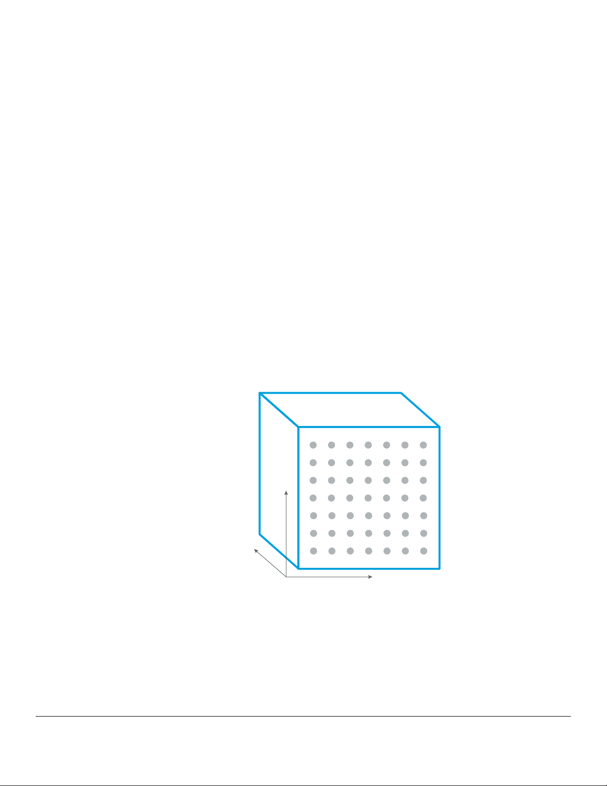
The HP Jet Fusion 3D Printing process involves selectively melting plastic powder. Once melted, the material cools
down until it solidifies, changing its internal structure. During solidification, the melted volume suffers from shrinkage.
Dimensional profiles are used to compensate the variation of this effect along the printing volume, automatically
applying geometrical transformations to each part being printed.
· Scaling
· 3D morphology
· Part by part
z
y
x
Figure 1. Representation of conceptually geometrical transformations managed by HP 3D Process Control
1. HP Jet Fu sion 3D Print ing Soluti ons using HP 3D High Re usabili ty PA 12 prov ide up to 80% p owder reusa bility ra tio, produc ing functional par ts batch af ter batch. Fo r testing, materi al
is aged i n real printing con ditions and powder is tracked by generations (worst case for reusa bility). Parts are then made f rom each generation and tested for mechanical prope rties
and accuracy.
Page 3
White p aper | HP 3D HR PA 12 for the HP Je t Fusion 5200 S eries 3D Pri nting Solu tion – Dimensional Ca pabilit y
Geometrical transformations are applied independently in each axis, ensuring optimal results for every part orientation.
For example, non-uniform scaling is used to compensate for shrinkage during the solidification process. In addition
to the volumetric compensations, dimensional profiles can act on the surface of the parts with axis-dependent 3D
morphology.
By default, the HP Jet Fusion 5200 Series 3D Printing Solution comes with general dimensional profiles. General profiles
are a unique type of dimensional profile that optimize part geometry based on the average behavior of a wide-sample
population of HP Jet Fusion 3D printers. Each print profile is associated to a general dimensional profile.
In addition, using HP 3D Process Control software, hardware-specific dimensional profiles can be generated and
managed to achieve optimized dimensional capability and help deliver uniform results across a fleet of printers. These
dimensional profiles can be used in use cases with very tight dimensional requirements, particularly when producing the
same type of parts in a fleet of printers, as they can balance the dimensional particularities of each device.
The Profile Management feature in HP 3D Process Control allows you to select different profiles depending on the
specific printing needs. For example:
• Trigger hardware-specic proling
• View all dimensional proles based on printer compatibility
• Congure the dimensional proles in use for each printer
General and hardware-specific dimensional profiles are generated by applying machine-learning techniques. HP uses the
data collected from different designs to build mathematical models that will generate predictions to optimize the jobs
when printing.
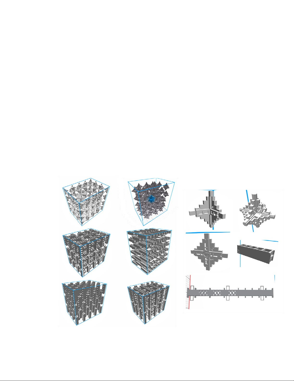
Figure 2 illustrates the geometries and jobs used to build the mathematical models.
Figure 2. Part geometries & job configurations used in
the calibration of dimensional profiles
Page 4
White p aper | HP 3D HR PA 12 for the HP Je t Fusion 5200 S eries 3D Pri nting Solu tion – Dimensional Ca pabilit y
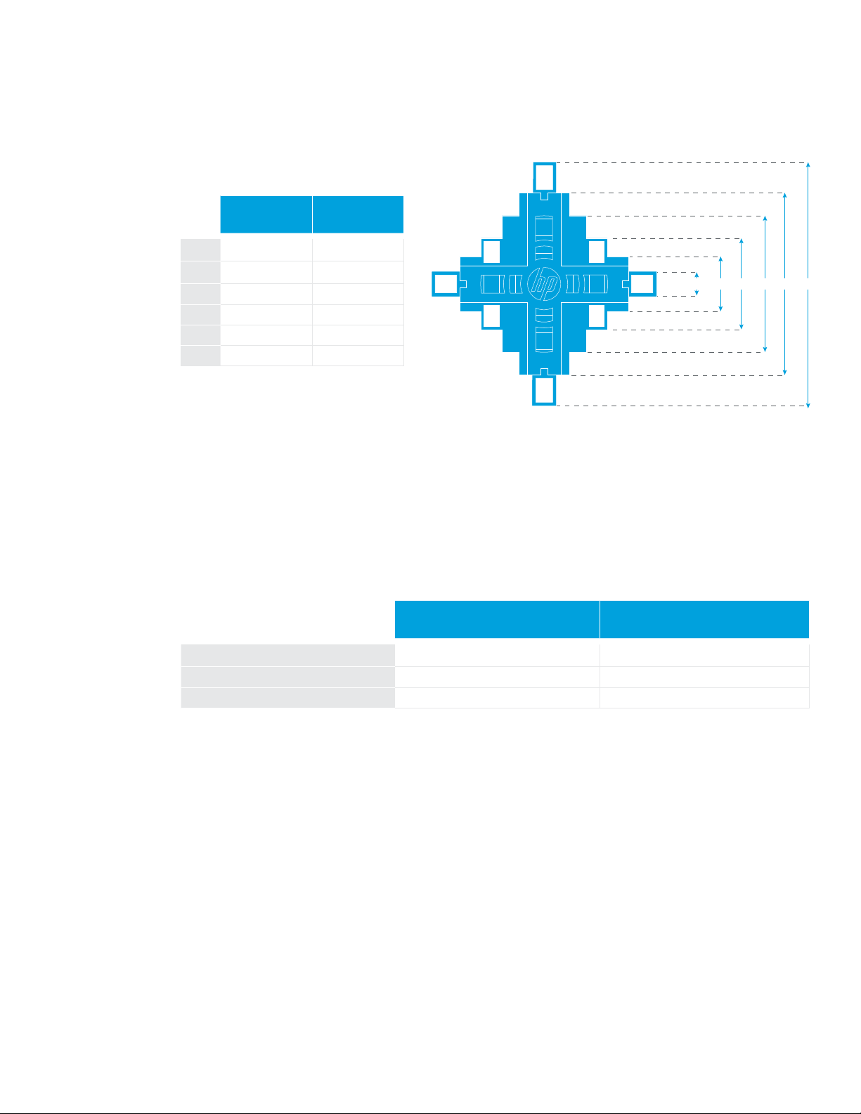
Each of these parts has different critical dimensions that are measured in each print. For example, some of the critical
dimensions collected for a specific part included in one of the jobs are shown in Figure 3.
Name Nominal/mm
1 He i g ht-1 8
2 Height-2 18
3 Height-3 30
4 Height-4 45
5 Height-5 60
6 Height-6 80
Figure 3. Diagnostic part critical dimensions
654321
To generate the general dimensional profile, the machine-learning model produces the correction based on the average
of all the printers that provide data. For the hardware-specific dimensional profile, the data collected from the specific
device are compared with the data from the overall population, and the correction is generated based on the average
measurement from printers with a similar configuration.
Table 1 shows the statistics of the overall data used by the machine learning process to improve the profile generation.
All data collected For a specific print profile
Critical dimensions ~600,000 ~10,000
Printers ~60 ~5
Jobs printed ~300 10
Table 1. Data collected to generate profiles
Page 5

White p aper | HP 3D HR PA 12 for the HP Je t Fusion 5200 S eries 3D Pri nting Solu tion – Dimensional Ca pabilit y
HP Jet Fusion 5200 Series 3D Printing Solution dimensional capability
performance
Test job
The dimensional capability performance of the HP Jet Fusion 5200 Series 3D Printing Solution with HP 3D HR PA 12 was
characterized using the HP dimensional capability characterization job (Figure 4), which contained 122 diagnostic parts
distributed throughout the printable volume. The job included three different types of diagnostic parts and a total of 1,524
dimensions.
Diagnostic parts
Middle (66X)
Figure 4. HP dimensional capability characterization job
Edge (16X)
Vertice (40X)
Page 6

White p aper | HP 3D HR PA 12 for the HP Je t Fusion 5200 S eries 3D Pri nting Solu tion – Dimensional Ca pabilit y
Performance results for HP 3D HR PA 12
Testing was performed for HP 3D HR PA 12 with a 20% refresh ratio using the PA 12 Balanced print profile, natural cooling,
and measured after bead-blasting with glass beads at 5-6 bars.
Table 2 shows the dimensional tolerances obtained during the characterization for a target process capability
(4 sigma).
Tolerances for Cpk = 1.33
(in mm)
i ii iii
2
of Cpk = 1.33
Nominal dimension
0 – 30 mm 30 – 50 mm 50 – 80 mm
XY Z XY Z XY Z
With the general dimensional profile for the
HP Jet Fusion 5200 Series 3D Printing Solution
With a hardware-specific dimensional profile
generated by HP 3D Process Control
i. Based o n internal testing a nd measured using th e HP dimensional ca pability chara cterization job. Re sults may vary with o ther jobs and geometrie s.
ii. Using H P 3D HR PA 12 material, 20% refresh rat io, Balanced print profile , natural cooling, and measu red after bead- blasting with glass b eads at 5-6 bars .
iii. Following all HP-recommended printer setup and adjustment processes and printheads aligned using semi-automatic procedure.
Table 2. Dimensional capabilities for HP 3D HR PA 12. Target process capability of Cpk = 1.33.
Table 3 shows the dimensional tolerances if the process capability target is set to C
±0.25 ±0.42 ±0.30 ±0.50 ± 0.37 ± 0.60
±0.17 ±0.25 ±0.20 ±0.30 ± 0.23 ± 0.37
= 1.00 (3 sigma).
pk
Nominal dimension
Tolerances for Cpk = 1.00
(in mm)
i ii iii
0 – 30 mm 30 – 50 mm 50 – 80 mm
XY Z XY Z XY Z
With the general dimensional profile for the
HP Jet Fusion 5200 Series 3D Printing Solution
±0.19 ±0.34 ±0.23 ±0.40 ± 0.28 ± 0.47
With a hardware-specific dimensional profile
generated by HP 3D Process Control
i. Based o n internal testing a nd measured using th e HP dimensional ca pability chara cterization job. Re sults may vary with o ther jobs and geometrie s.
ii. Using H P 3D HR PA 12 material, 20% refresh rat io, Balanced print profile , natural cooling, and measu red after bead- blasting with glass b eads at 5-6 bars ..
iii. Following all HP-recommended printer setup and adjustment processes and printheads aligned using semi-automatic procedure
Table 3. Dimensional capabilities for HP 3D HR PA 12. Target process capability of Cpk = 1.00.
2. For more information on process capabilities, see Appendix 1: Understanding process capabilities.
±0.13 ±0.21 ±0.16 ±0.25 ± 0 .18 ± 0.30
Page 7

White p aper | HP 3D HR PA 12 for the HP Je t Fusion 5200 S eries 3D Pri nting Solu tion – Dimensional Ca pabilit y
For this specific test job, and as shown in Figure 5 and Figure 6, the HP Jet Fusion 5200 Series 3D Printing Solution was able to
provide manufacturing-grade dimensional capability (C
Based on the table above, when the dimensional capability target is reduced to C
Printing Solution was able to provide a tolerance grade IT12.5 in XY and IT13.5 in Z.
HP Jet Fusion 5200 Series 3D Printing Solution | Dimensional capability vs. IT grades
0.65
0.60
0.55
0.50
0.45
0.40
0.35
± tolerance [mm]
0.30
0.25
0.20
0.15
0.10
0.05
0
10 20 30 6040 7050 80
Nominal dimension [mm]
= 1.33) for a tolerance grade3 IT13 in XY and IT14 in Z.
pk
= 1.00, the HP Jet Fusion 5200 Series 3D
pk
IT 15
IT 14
IT 13
IT 12
IT 11
XY Cpk = 1.33 with HW-specic dimensional prole Z Cpk = 1.33 with HW-specic dimensional prole
Figure 5. Dimensional capability vs. IT grade for Cpk = 1.33
HP Jet Fusion 5200 Series 3D Printing Solution | Dimensional capability vs. IT grades
0.65
0.60
0.55
0.50
0.45
0.40
0.35
± tolerance [mm]
0.30
0.25
0.20
0.15
0.10
0.05
0
10 20 30 6040 7050 80
Nominal dimension [mm]
IT 15
IT 14
IT 13
IT 12
IT 11
XY Cpk = 1.00 with HW-specic dimensional prole Z Cpk = 1.00 with HW-specic dimensional prole
Figure 6. Dimensional capability vs. IT grade for C
3. For more information on IT grades, see Appendix 2: Dimen sional requ irements & IT grad es
= 1.00.
pk
Page 8

Accurate, but not repeatable
Good bias (low) but high variability
Both, repeatable and accurate
Low bias and good C
P
so Cpk is good
Both, repeatable and accurate
Low bias and good C
P
so Cpk is good
White p aper | HP 3D HR PA 12 for the HP Je t Fusion 5200 S eries 3D Pri nting Solu tion – Dimensional Ca pabilit y
Appendix 1: Understanding process capabilities
Process capability determines whether a process meets a specification. The process capability index or process capability ratio
(C
) is a statistical measure of process capability. It quantifies the ability of a process to produce output within specification
pk
limits.
When talking about a dimensional specification, the C
dimension within its tolerance range. The higher the C
measures the statistical probability that a certain process produces a
pk
value the better, meaning that more measurements will be within the
pk
tolerance range.
For a process to be capable, it needs to be both repeatable and accurate.
Repeatability is how close multiple measurements are to each other (also called precision).
Accuracy is how close a measurement value is to the specified nominal.
The capability of a process is then a function of two parameters:
• How repeatable it is compared to the width of the specification limits, measured by the C
• How accurate it is, measured by the bias
Capability = Cpk = Cp * (1-2*bias)
Repeatable, but not accurate
Accurate, but not repeatable
p
Both, repeatable and accurate
(low variability) but high bias
Good C
P
Good bias (low) but high variability
Figure 7: Relationship between bias and variability
Low bias and good C
so Cpk is good
P
This concept only holds meaning for processes that are in a state of statistical control with an output that is approximately
normally distributed.
Both conditions happen when dealing with the dimensional quality control of HP MJF–produced parts where the output is the
dimensional value of the different geometrical features of a part.
Dimensional quality control processes define an upper specification limit (USL) and lower specification limit (LSL), also called
the “tolerance range” of the process. The target of the process is the center of this range, typically the nominal dimension
value.
The objective to have a well-controlled dimensional process is to have its normal distributed population of measurements:
• With a variability (calculated as standard deviation) that “fits” in the tolerance range. C
measures how well the variability
p
fits within the tolerance range.
•With a mean (average) as close as possible to the target. The deviation is measured by the bias.
Page 9

White p aper | HP 3D HR PA 12 for the HP Je t Fusion 5200 S eries 3D Pri nting Solu tion – Dimensional Ca pabilit y
Only if both conditions are met, process capability measured by Cpk is considered good:
Poor C
Lower
spec
High Bias
Low variability,
ts in tolerance range, high C
p
pk
Nominal
Upper
spec
Lower
spec
does not t in tolerance range, low C
Figure 8. Process capability Cpk scenarios
The mathematical calculation of these parameters is as follows:
Specification width = (USL - LSL)
Cp =
Process width 6σ
Poor C
Nominal
Low Bias
High variability,
pk
Upper
spec
p
Lower
Good C
spec
Low variability,
ts in tolerance range, high C
pk
Nominal
Low Bias
Upper
spec
p
Standard deviation estimates the sigma and quantifies the variability and dispersion of the process.
C
should always be greater than 1.00 for the variability to fit within the tolerance range.
p
Cpk = min
[USL - µ� , [µ - LSL�
3 · σ 3 · σ
The statistical mean estimates the mu (µ).
Therefore:
• C
“measures” the distance of the mean to the closer specification limit, which could be the upper or the lower limit.
pk
takes into account how centered the process is (Cpk ≤ Cp).
• C
pk
• For a perfectly centered process, C
> Cpk, it is possible to increase the Cpk by readjusting the mean of the process.
• If C
p
= Cpk.
p
Page 10

White p aper | HP 3D HR PA 12 for the HP Je t Fusion 5200 S eries 3D Pri nting Solu tion – Dimensional Ca pabilit y
Table 4 displays the relevant Cpk values and their correlation with process yields.
100 %
inspection
C
pk
Sigma
level
Dimensions
within specs (%)
Dimensions
out of specs
(units per million)
0.33 1 68.27 317, 3 0 0 2.20
0.67 2 95.45 45,500 62.77
Part yield for a part
with 10 dimensions
(%)
1.00 3 99.73 2,700 97. 33
Statistical
process
1.33 4 99.9937 63 99.94 Desired
1.50 5 99.99966 3.4 100
control
1.67 6 99.99997 0.6 100
Table 4. Cpk and process yield correlation
For a part to be considered good, all the specified dimensions need to be within tolerances. Therefore, the part yield is a metric
that can be calculated as the statistical sum of the single dimension success rate. In Table 4, an example for a part with 10
dimensions is shown in the right column.
For C
values below 1.00, the yield is such that the best quality control method is 100% inspection, and the general fabrication
pk
process is to over-produce and send only the parts that meet the tolerance requirements. This is a costly but reasonable
process, especially for low-volume production.
For C
values above 1.00 (3 sigma), the dimensional success rate and the yield begin to approach each other, and statistical
pk
process control starts to become a viable option. This means that after the process has demonstrated that it is statistically and
consistently achieving C
Generally, a C
of 1.33 (4 sigma) is desired to ensure enough of a margin for statistical process control, especially when dealing
pk
above 1.00 for all dimensions, random parts could be audited for each lot of parts.
pk
with multi-part complex mechanisms.
Page 11

White p aper | HP 3D HR PA 12 for the HP Je t Fusion 5200 S eries 3D Pri nting Solu tion – Dimensional Ca pabilit y
Tolerance range vs. dimension length
Appendix 2: Dimensional requirements & IT grades
The International Tolerance grades (IT grades) defined in ISO 286/ ANSI B4.2-1978 provide standardized tolerance ranges. The
smaller the IT grade, the smaller the tolerance range, meaning better dimensional performance (less variability).
Each IT grade has a tolerance range that varies depending on the nominal value of the dimension. The larger the specified
dimension, the larger the tolerance range for accuracy.
Dimension (mm) IT1 IT2 IT3 IT4 IT5 IT6 IT7 IT8 IT9 IT10 I T11 I T12 IT13 IT14 IT15
Up to and
Above
including
- 3 0.8 1.2 2 3 4 6 14 10 25 40 60 0.10 0.14 0.25 0.4
3 6 1 1.5 2.5 4 5 8 18 12 30 48 75 0 .12 0.18 0.30 0.48
6 10 1 1.5 2.5 4 6 9 22 15 36 58 90 0.15 0.22 0.36 0.58
10 18 1.2 2 3 5 8 11 27 18 43 70 110 0 .18 0.27 0.43 0.70
18 30 1.5 2.5 4 6 9 13 33 21 52 84 130 0.21 0.33 0.52 0.84
30 50 1. 5 2.5 4 7 11 16 39 25 62 10 0 16 0 0.25 0.39 0.62 1.00
50 80 2 3 4 8 13 19 46 30 74 12 0 190 0.30 0.46 0.74 1.20
80 12 0 2.5 4 6 10 15 22 54 35 87 140 220 0.35 0.54 0.87 1.40
120 180 3.5 5 8 12 18 25 63 40 100 16 0 250 0.40 0.63 1.00 1.60
180 250 4.5 7 10 14 22 29 72 46 115 185 290 0.46 0.72 1.15 1.85
250 315 6 8 12 16 23 32 81 52 130 210 320 0.52 0.81 1.30 2.10
315 400 7 9 13 18 25 36 89 57 140 230 360 0.57 0.89 1.40 2.30
400 500 8 10 15 20 27 40 97 63 155 250 400 0.63 0.97 1.55 2.50
500 630 9 11 16 22 32 44 100 70 175 280 440 0.70 1.10 1.75 2.80
Table 5. Standard international tolerance grades
µm Tolerance ranges mm
2.5
2
1.5
1
± tolerance [mm]
0.5
0
50 100 150 300200 350250 400
dimension length [mm]
Figure 9. Tolerance range vs. dimension length
IT grades provide a standardized reference to compare typical manufacturing process capability in terms of dimensional
tolerance for a given dimension, as shown in Table 6.
Measuring tools Material
IT Grade 01 0 1 2 3 4 5 6 7 8 9 10 11 12 13 14 15 16
Large manufacturing
tolerances
Better
Fits
Table 6. IT Grades for measuring tools & materials
IT 15
IT 14
IT 13
IT 12
IT 11
Page 12

White p aper | HP 3D HR PA 12 for the HP Je t Fusion 5200 S eries 3D Pri nting Solu tion – Dimensional Ca pabilit y
Appendix 3: Key terms
• Process capability: Statistical measurement of a process’s ability to produce parts within specified limits on a consistent
basis.
• International Tolerance Grade (IT Grade): Grade used to identify the tolerances a given industrial process can produce for a
given dimension.
• Repeatability: Ability of a process to consistently produce the same output; in this case, the same part dimensions.
• Bias: Difference between the average of the population for a given dimension and the target value of that dimension.
: Process capability index that measures of the ability of a process to produce consistent results – the ratio between the
• C
p
permissible spread and the actual spread of a process. This does not take into account how well the output is centered on
the target (nominal) value.
• C
: Process capability index that estimates what the process is capable of producing, considering that the process mean
pk
may not be centered between the specification limits. C
• HP 3D Process Control: HP proprietary software tool. HP 3D Process Control targets both print accuracy and repeatability
by reducing dimensional variability across the entire printable area through machine learning-based algorithms.
Dimensional profiles are created and stored in the tool’s profile library, establishing a guideline for fundamental process
control across a fleet of machines for both local and distributed sites.
• Dimensional profile: Specific configuration used to compensate for variations in printed geometry along the printing
volume. Through the dimensional profile, geometrical transformations are applied automatically on each axis to ensures
optimal results for every part feature.
• General dimensional profile: Default dimensional profile available for each print profile in the HP Jet Fusion 5200 Series 3D
Printing Solution, based on the average behavior of a wide sample population of HP Jet Fusion 3D printers.
• Hardware-specific dimensional profile: Dimensional profile specifically configured to compensate for possible variations
in a specific printer to achieve the nominal value of the calibration job.
< 0 if the process mean falls outside of the specification limits.
pk
© Copyr ight 2020 HP Development Compa ny, L.P.
The information contained h erein is provided for information purposes only. The only terms an d conditions gove rning the sale of HP 3D printer solutions are
those set for th in a written sales agreeme nt. The only warra nties for HP products and ser vices are set forth in the express warranty statements a ccompanyi ng
such products and ser vices. Nothing herein shou ld be constru ed as constit uting an add itional warranty or addit ional binding terms an d condition s. HP shall not
be liable for technical or editoria l errors or om issions contained herein and the information herein is subject to change wi thout notice.
4AA7-7138ENW, Aug ust 2020
 Loading...