

Page 1

3Com VCX IP Telecommuting
Module
Getting started Guide
Page 2

Page 3

3Com VCX IP Telecommuting Module: Getting started Guide
Part Number BETA
Published April 2009
3Com Corporation, 350 Campus Drive, Marlborough MA 01752-3064
Copyright © 2005, 3Com Corporation. All rights reserved. No part of this documentation may be reproduced in any
form or by any means or used to make any derivative work (such as translation, transformation, or adaptation)
without written permission from 3Com Corporation.
3Com Corporation reserves the right to revise this documentation and to make changes in content from time to time
without obligation on the part of 3Com Corporation to provide notification of such revision or change.
3Com Corporation provides this documentation without warranty, term, or condition of any kind, either implied or
expressed, including, but not limited to, the implied warranties, terms, or conditions of merchantability, satisfactory
quality, and fitness for a particular purpose. 3Com may make improvements or changes in the product(s) and/or the
program(s) described in this documentation at any time.
If there is any software on removable media described in this documentation, it is furnished under a license
agreement included with the product as a separate document, in the hardcopy documentation, or on the removable
media in a directory file named LICENSE.TXT or !LICENSE.TXT. If you are unable to locate a copy, please contact
3Com and a copy will be provided to you.
UNITED STATES GOVERNMENT LEGEND
If you are a United States government agency, then this documentation and the software described herein are
provided to you subject to the following:
All technical data and computer software are commercial in nature and developed solely at private expense. Software
is delivered as "Commercial Computer Software" as defined in DFARS 252.227-7014 (June 1995) or as a
"commercial item" as defined in FAR 2.101(a) and as such is provided with only such rights as are provided in
3Com’s standard commercial license for the Software. Technical data is provided with limited rights only as provided
in DFAR 252.227-7015 (Nov 1995) or FAR 52.227-14 (June 1987), whichever is applicable. You agree not to remove
or deface any portion of any legend provided on any licensed program or documentation contained in, or delivered to
you in conjunction with, this guide.
Unless otherwise indicated, 3Com registered trademarks are registered in the United States and may or may not be
registered in other countries.
3Com, the 3Com logo, NBX, and SuperStack are registered trademarks of 3Com Corporation. NBX NetSet, pcXset,
and VCX are trademarks of 3Com Corporation.
Adobe is a trademark and Adobe Acrobat is a registered trademark of Adobe Systems Incorporated. Microsoft,
Windows, Windows 2000, Windows NT, and Microsoft Word are registered trademarks of Microsoft Corporation.
All other company and product names may be trademarks of the respective companies with which they are associated.
Page 4

Page 5

Table of Contents
Part I. Installation of the 3Com VCX IP Telecommuting Module ...................................i
1. Introduction................................................................................................................1
2. Overview of the Installation.......................................................................................3
3. Installing 3Com VCX IP Telecommuting Module ....................................................5
Part II. Configuring 3Com VCX IP Telecommuting Module ........................................ 15
4. Network Configuration ............................................................................................17
5. SIP Configuration ....................................................................................................35
6. Administration of the Telecommuting Module........................................................47
7. Firewall and Client Configuration............................................................................57
Index ............................................................................................................................61
i
Page 6

ii
Page 7

Part I. Installation of the 3Com
VCX IP Telecommuting Module
This document will help you to get started with your 3Com VCX IP Telecommuting Module.
It contains the necessary information to configure your Telecommuting Module.
Additional information about managing your 3Com VCX IP Telecommuting Module can be
found in the Reference Guide.
These chapters contain an introduction to the 3Com VCX IP Telecommuting Module, descriptions of the various models and information about how to install your Telecommuting
Module.
Page 8

Page 9

Chapter 1. Introduction
What is a Telecommuting Module?
A Telecommuting Module is a device which processes traffic under the SIP protocol (see
RFC 3261). The Telecommuting Module receives SIP requests, processes them according to
the rules you have set up, and forwards them to the receiver.
The Telecommuting Module connects to an existing enterprise firewall through a DMZ port,
enabling the transmission of SIP-based communications without affecting firewall security.
SIP messages are then routed through the firewall to the private IP addresses of authorized
users on the internal network.
The Telecommuting Module can also be used as an extra gateway to the internal network
without connecting to the firewall, transmitting only SIP-based communications.
Configuration alternatives
The 3Com VCX IP Telecommuting Module can be connected to your network in three
different ways, depending on your needs.
Note that if the Standalone type is used, the interface which should receive traffic from the
outside must have a public IP address (no NAT).
For a DMZ or DMZ/LAN type which uses a private IP address on the interface connected
to the DMZ of the firewall, its corresponding public IP address must be entered on the
Interoperability page.
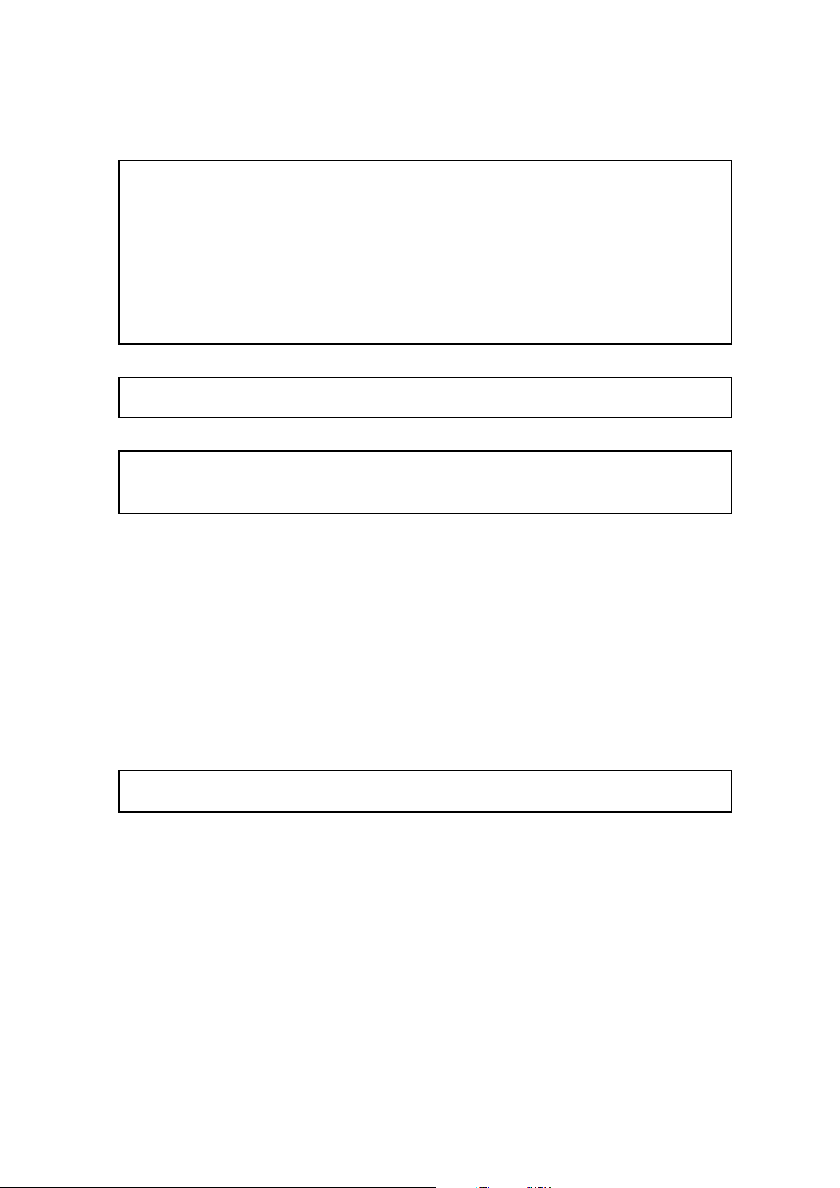
DMZ Configuration
Using this configuration, the Telecommuting Module is located on the DMZ of your firewall,
and connected to it with only one interface. The SIP traffic finds its way to the Telecommuting Module using DNS or by setting the Telecommuting Module as an outbound proxy on
the clients.
This is the most secure configuration, since all traffic goes through both your firewall and
your Telecommuting Module. It is also the most flexible, since all networks connected to
any of your firewall’s interfaces can be SIP-enabled.
The drawback is that the SIP traffic will pass the firewall twice, which can decrease performance.
1
Page 10

Chapter 1. Introduction
Fig 1. Telecommuting Module in DMZ configuration.
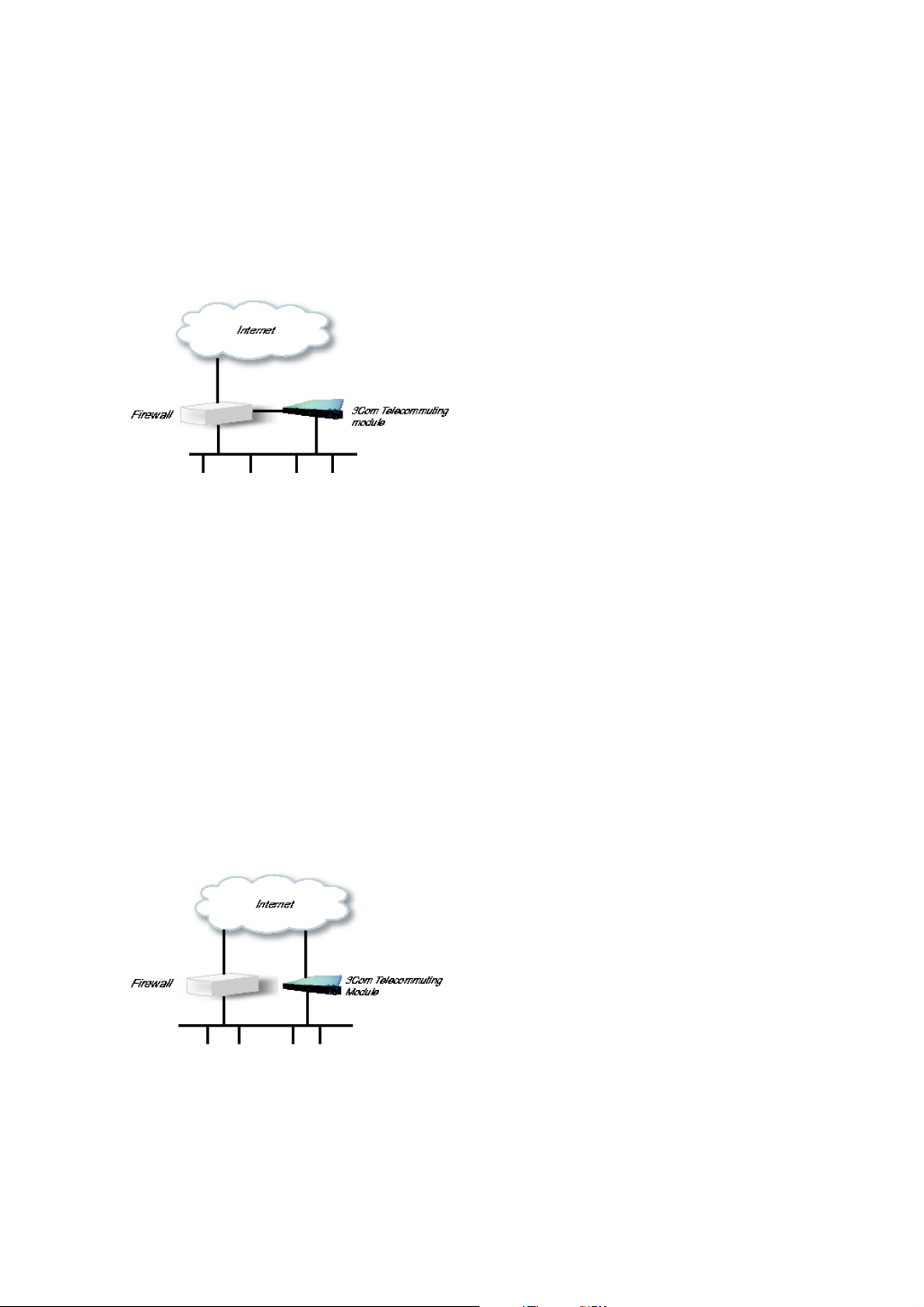
DMZ/LAN Configuration
Using this configuration, the Telecommuting Module is located on the DMZ of your firewall,
and connected to it with one of the interfaces. The other interfaces are connected to your
internal networks. The Telecommuting Module can handle several networks on the internal
interface even if they are hidden behind routers.
This configuration is used to enhance the data throughput, since the traffic only needs to pass
your firewall once.
Fig 2. Telecommuting Module in DMZ/LAN configuration.
Standalone Configuration
Using this configuration, the Telecommuting Module is connected to the outside on one
interface and your internal networks on the others.
Use this configuration only if your firewall lacks a DMZ interface, or for some other reason
cannot be configured for the DMZ or DMZ/LAN alternatives.
Fig 3. Telecommuting Module in Standalone configuration.
2
Page 11

Chapter 2. Overview of the Installation
• Now you can see the main page of 3Com VCX IP Telecommuting Module. Click on the
Telecommuting Module Type link and select the configuration for your Telecommuting
Module. The types are described on the corresponding help page.
• Go to the Basic Configuration page and enter a DNS server. See also the Basic Config-
uration section.
• Go to the Access Control page and make settings for the configuration of the Telecom-
muting Module. See also the Access Control section.
• Go to the Network Interface 1 page under Network Configuration and enter the neces-
sary configuration. See also the Interface section. Note that the Telecommuting Module
must have at least one IP address which can be reached from the Internet.
• If one of the Telecommuting Module Types DMZ/LAN or Standalone was chosen, move
on to the Network Interface 2 page and give the Telecommuting Module at least one IP
address on this interface and state the networks connected to the interface. See also the
Interface section.
• Go to the Default Gateway page and enter a Default gateway. See also the Default
Gateway section.
• Go to the Networks and Computers page. Define the networks that will send and receive
SIP traffic using the Telecommuting Module. Usually, you need at least one network per
interface of the firewall connected to the Telecommuting Module (or, for the Standalone
type, per interface of the Telecommuting Module). Some computers should be handled
separately, and they therefore need their own networks. See also the Networks and Computers section.
• Go to the Surroundings page (for the DMZ Telecommuting Module Type) and state the
networks connected to the firewall. See also the Surroundings section in chapter 8 of the
User Manual.
• Go to Basic Settings under SIP Services and switch the SIP module on. Enter the port
range to be used by the Telecommuting Module for the media streams. See also the Basic
Settings section.
• Go to the Filtering page under SIP Traffic to create Proxy rules for the SIP traffic from
different networks and allow the content types which should be allowed in the SIP media
streams. See also the Filtering section.
• Go to the Interoperability page. Set URI Encoding to "Keep username in URIs".
• Go to the Save/Load Configuration page under Administration. Select Apply configu-
ration. Now you can test your new configuration and save it permanently if you are satisfied with it. If the configuration is not satisfactory, select Revert or restart the Telecommuting Module. The old configuration will remain.
• When the configuration has been applied, you should save a backup to file. Press Save to
local file to save the configuration.
When the Telecommuting Module is configured, the firewall connected to it must also be
reconfigured (for the DMZ and DMZ/LAN Telecommuting Module Types).
3
Page 12

Chapter 2. Overview of the Installation
• Allow UDP and TCP traffic in the port interval used for media streams by the Telecom-
muting Module, and port 5060. This traffic must be allowed to all networks which should
be reached by SIP traffic.
See also the chapter titled Firewall and Client Configuration, for information on configuring
the firewall and the SIP clients.
About settings in 3Com VCX IP Telecommuting Module
3Com VCX IP Telecommuting Module uses two sets of Telecommuting Module configurations: preliminary and permanent configuration. The permanent configuration is what
is used in the active Telecommuting Module. The preliminary configuration is where you
change and set the configuration. See chapter 3 of the User Manual for instructions.
The changes you make in the preliminary configuration are not stored in the permanent
configuration until you click on Apply configuration on the Save/Load Configuration
page under Administration.
The password configuration and time setting are the exceptions to this rule; they are saved
immediately. Change the administrator passwords and create more administrator users on
the User Administration page under Administration.
3Com VCX IP Telecommuting Module displays serious errors in red, e.g., if mandatory
information is not entered. Blank fields are shown in red. Fields that you correct remain red
until you select Save, Add new rows or update the page in some other way.
If you have a web connection with the Telecommuting Module that is inactive for 10 minutes, it will ask for a password again.
Always log out from the Telecommuting Module administration interface when you are not
using it. Press the Log out button on the left to log out.
The terms used in the book are explained in appendix C of the User Manual.
For a general description of how to configure and administer the Telecommuting Module,
see chapter 3 of the User Manual.
License Conditions
To fulfill the license conditions, we must either attach the source code with the software, or
send a written offer, valid at least three years, to give a copy of the source code to anyone
who wants it. According to 3b) of the license, we are entitled to charge for the distribution
of the source code.
3Com Corporation offer the source code for all third party software included in 3Com VCX
IP Telecommuting Module and licensed under GPL. This offer is valid for this version of
3Com VCX IP Telecommuting Module and is valid for three years after deliverance of
your 3Com VCX IP Telecommuting Module unit. Contact 3Com Corporation for current
information.
4
Page 13

Chapter 3. Installing 3Com VCX IP Telecommuting Module
Installation
There are three ways to install an 3Com VCX IP Telecommuting Module: using a serial
cable, using a diskette or perform a magic ping.
Installation with a serial cable or a diskette requires being at the same place as the Telecommuting Module, but will give more options for the start configuration.
Installation with magic ping does not require being on the same place as the Telecommuting
Module (but the computer has to be connected to the same logical network as the Telecommuting Module), but restricts the start configuration.
Installation with magic ping
You can use the magic ping to set an IP address for the Telecommuting Module. This is how
to perform a magic ping:
• Plug in the power cord and turn the Telecommuting Module on.
• Wait while the Telecommuting Module boots up.
• Connect the network cables to the network interfaces.
• Find out the MAC address of the Telecommuting Module (printed on the Telecommuting
Module label). This is the MAC address of Network Interface 1.
• Add a static entry in your local ARP table consisting of the Telecommuting Module’s
MAC address and the IP address it should have on eth0.
This is how to add a static ARP entry if you use a Windows computer:
Run the command command (or cmd).
In the Command window, enter the command arp -s ipaddress macaddress where ipad-
dress is the new IP address for the eth0 interface, and macaddress is the MAC address
printed on the Telecommuting Module, but with all colons (:) replaced with dashes (-).
• Ping this IP address to give the Telecommuting Module its new IP address. You should
receive a ping reply if the address distribution was successful.
• Configure the rest through a web browser.
The magic ping will not set any password. Set a password immediately via the web user
interface. Before any configuration has been made, only the computer which performed the
magic ping will be able to configure the 3Com VCX IP Telecommuting Module.
Installation with a serial cable
These steps are performed when installing with a serial cable:
5
Page 14

Chapter 3. Installing 3Com VCX IP Telecommuting Module
• Connect the Telecommuting Module to your workstation with the enclosed serial cable.
• Plug in the power cord and turn the Telecommuting Module on.
• Wait while the Telecommuting Module boots up.
• Log on from your workstation.
• Run the installation program (see following instructions).
• Connect the network cables to the network interfaces.
• Configure the rest through a web browser.
Connect the Telecommuting Module to your workstation with the enclosed serial cable,
plug in the power cord and turn the Telecommuting Module on. You will have to wait a few
minutes while it boots up.
• If you use a Windows workstation, connect like this: Start Hyperterm. A Location dia-
logue will show, asking for your telephone number and area. Click Cancel followed by
Yes. Then you will be asked to make a new connection. Type a name for this connection, select an icon and click OK. The Location dialogue will show again, so click Cancel
followed by Yes.
Now you can select Connect using COM1 and click OK. A Port settings dialogue will
show, where you select 19200 as Bits per second. Use the default configuration for all
other settings. Click OK and wait for a login prompt. (In some cases you have to press
Return to get the login prompt.)
• If you use a Linux workstation, connect like this: Make sure that there is a symbolic
link named /dev/modem which points to the serial port you connected the Telecommuting
Module to. Connect using minicom with the bit rate 19200 bits/s, and wait for a login
prompt.
Log on as the user admin. The first time you log on, no password is required. You set the
password when you run the installation script, which starts automatically when you have
logged on.
Each network interface is marked with a name (1 and 2), which corresponds to a tab under
Network Configuration. All eth interfaces belong to ethernet cards and should only be
connected using ethernet cables.
Decide which computer(s) are allowed to configure 3Com VCX IP Telecommuting Module
and enter the name of the network interface to which they are connected, for example, eth0.
You must use the physical device name (eth0 and eth1).
Enter the IP address of the Telecommuting Module on this interface and the network mask
for the network.
A network mask can be written in two ways in 3Com VCX IP Telecommuting Module:
• The first looks just like an IP address, for example 255.255.192.0 or 255.255.254.0.
6
Page 15

Chapter 3. Installing 3Com VCX IP Telecommuting Module
• The other way is as a number between 0 and 32. An IP address has 32 bits, where the
number of the network mask indicates how many bits are used in the network’s addresses.
The rest of the bits identifies the computer on the network.
Now, you can select to deactivate any network interfaces. Select y to deactivate all interfaces
but the one you just configured. The remaining network interfaces can be activated later
when you complete the configuration via the web interface from your work station. This
only applies to interfaces which was previously active; you can’t activate interfaces with this
setting.
Now enter the computer or computers from which the Telecommuting Module may be configured (the configuration computers).
Then enter a password for the Telecommuting Module. This is the password you use in your
web browser to access and change the Telecommuting Module’s configuration. Finally, you
can reset all other configuration if you want to.
Following is a sample run of the installation program.
3Com VCX IP Telecommuting Module Administration
1. Basic configuration
2. Save/Load configuration
5. Wipe email logs
6. Set password
7. Command line interface
a. About
q. Exit admin
==>
Select 1 to install your 3Com VCX IP Telecommuting Module.
Basic unit installation program version 4.6.5
Press return to keep the default value
Network configuration inside:
Physical device name[eth0]:
IP address [0.0.0.0]: 10.47.2.242
Netmask/bits [255.255.255.0]: 255.255.0.0
Deactivate other interfaces? (y/n) [n]
Computers from which configuration is allowed:
You can select either a single computer or a network.
Configure from a single computer? (y/n) [y]
7
Page 16

Chapter 3. Installing 3Com VCX IP Telecommuting Module
If you choose to allow only one computer to configure the Telecommuting Module, you are
asked for the IP address (the mask is set automatically).
IP address [0.0.0.0]: 10.47.2.240
If this IP address is not on the same network as the IP address of the Telecommuting Module, you are asked for the router. Enter the IP address of the router on the network where
the Telecommuting Module is connected. Then enter the network address and mask of the
network containing the configuring computer.
Static routing:
The computer allowed to configure from is not on a network local to
this unit. You must configure a static route to it. Give
the IP address of the router on the network the unit is on.
The IP address of the router [0.0.0.0]: 10.47.3.1
Network address [10.47.0.0]: 10.10.0.0
Netmask [255.255.255.0]:
You can choose to allow several computers to configure the Telecommuting Module, by
answering no to the question:
Configure from a single computer? (y/n) [y] n
The installation program then asks for the network number. The configuration computers
must be entered as a complete subnet, i. e. a range which can be written as a network number
and a netmask (like 10.47.2.128 with netmask 255.255.255.128, which means the computers
10.47.2.128-10.47.2.255). All computers on this subnet will be allowed to configure the
Telecommuting Module. For more information about network numbers and netmasks, see
chapter 3 of the User Manual.
Network number [0.0.0.0]: 10.47.2.0
Netmask/bits [255.255.255.0]: 255.255.255.0
If the network or partial network is not directly connected to the Telecommuting Module,
you must enter the IP address of the router leading to that network. Then enter the network’s
address and mask.
Static routing:
The network allowed to configure from is not on a network local to this
unit. You must configure a static route to it. Give the
IP address of the router on the network this unit is on.
The IP address of the router [0.0.0.0]: 10.47.3.1
Network address [10.47.0.0]: 10.10.0.0
Netmask [255.255.255.0]:
Then enter a password.
8
Page 17

Chapter 3. Installing 3Com VCX IP Telecommuting Module
Password []:
Finally, you are asked if you want to reset other configuration.
Other configuration
Do you want to reset the rest of the configuration? (y/n) [n]
If you answer n, nothing is removed. If you answer y, you have three alternatives to select
from:
1. Clear as little as possible. This is the alternative that is used if you answer n to the
question above. Both the preliminary and the permanent configurations will be updated
with the configuration specified above.
2. Revert to the factory configuration and then apply the configuration specified above.
This will affect the permanent but not the preliminary configuration.
3. Revert to the factory configuration and empty all logs and then apply the configuration
specified above. Both the preliminary and the permanent configurations will be affected.
Select the update mode, which is what you want to remove.
Update mode (1-3) [1]:
All configuration is now complete. The installation program shows the configuration and
asks if it is correct.
yes saves the configuration.
no runs the installation program over again.
abort ends the installation program without saving.
You have now entered the following configuration
Network configuration inside:
Physical device name: eth0
IP address: 192.168.150.2
Netmask: 255.255.255.0
Deactivate other interfaces: no
Computer allowed to configure from:
IP address: 192.168.128.3
Password: eeyore
The rest of the configuration is kept.
Is this configuration correct (yes/no/abort)? yes
9
Page 18

Chapter 3. Installing 3Com VCX IP Telecommuting Module
Now, finish configuration of the Telecommuting Module from the computer/computers specified in the installation program.
Installation with a diskette
These steps are performed when installing with a diskette:
• Select an IP address and store it on the installation diskette as described below.
• Insert the installation diskette into the Telecommuting Module’s floppy drive.
• Plug in the power cord and turn the Telecommuting Module on.
• Connect the network cables to the network interfaces.
• Wait while the Telecommuting Module boots up.
• Configure the rest through a web browser.
You must first insert the diskette into your PC. If the PC is running Windows, open a Command window and run the finst-en script from the diskette. If the PC is running Linux, mount
the diskette, change directory to the mounted one, and run the finst-en script.
Each network interface is marked with a name (1 and 2), which corresponds to a tab under
Network Configuration. All eth interfaces belong to ethernet cards and should only be
connected using ethernet cables.
Decide which computer(s) are allowed to configure 3Com VCX IP Telecommuting Module
and enter the name of the network interface to which they are connected, for example, eth0.
You must use the physical device name (eth0 and eth1).
Enter the IP address of the Telecommuting Module on this interface and the network mask
for the network.
A network mask can be written in two ways in 3Com VCX IP Telecommuting Module:
• The first looks just like an IP address, for example 255.255.192.0 or 255.255.254.0.
• The other way is as a number between 0 and 32. An IP address has 32 bits, where the
number of the network mask indicates how many bits are used in the network’s addresses.
The rest of the bits identifies the computer on the network.
Now, you can select to deactivate any network interfaces. Select y to deactivate all interfaces
but the one you just configured. The remaining network interfaces can be activated later
when you complete the configuration via the web interface from your work station. This
only applies to interfaces which was previously active; you can’t activate interfaces with this
setting.
Now enter the computer or computers from which the Telecommuting Module may be configured (the configuration computers).
Then enter a password for the Telecommuting Module. This is the password you use in your
web browser to access and change the Telecommuting Module’s configuration. Finally, you
can reset all other configuration if you want to.
Following is a sample run of the installation program on the diskette.
10
Page 19

Chapter 3. Installing 3Com VCX IP Telecommuting Module
Basic unit installation program version 4.6.5
Press return to keep the default value
Network configuration inside:
Physical device name[eth0]:
IP address [0.0.0.0]: 10.47.2.242
Netmask/bits [255.255.255.0]: 255.255.0.0
Deactivate other interfaces? (y/n) [n]
Computers from which configuration is allowed:
You can select either a single computer or a network.
Configure from a single computer? (y/n) [y]
If you choose to allow only one computer to configure the Telecommuting Module, you are
asked for the IP address (the netmask is set automatically).
IP address [0.0.0.0]: 10.47.2.240
If this IP address is not on the same network as the inside of the Telecommuting Module,
you are asked for the router. Enter the IP address of the router on the network where the
Telecommuting Module is connected. Now enter the network address and mask of the network containing the configuring computer.
Static routing:
The computer allowed to configure from is not on a network local to
this unit. You must configure a static route to it. Give
the IP address of the router on the network the unit is on.
The IP address of the router [0.0.0.0]: 10.47.3.1
Network address [10.47.0.0]: 10.10.0.0
Netmask [255.255.255.0]:
You can choose to allow several computers to configure the Telecommuting Module, by
answering no to the question:
Configure from a single computer? (y/n) [y] n
The installation program then asks for the network number. The network number is the
lowest IP address in the series of numbers that includes the configuration computers (see
chapter 3 of the User Manual). The network mask determines the number of computers that
can act as configuration computers.
Network number [0.0.0.0]: 10.47.2.0
Netmask/bits [255.255.255.0]: 255.255.255.0
11
Page 20
Chapter 3. Installing 3Com VCX IP Telecommuting Module
If the network or partial network is not directly connected to the Telecommuting Module,
you must enter the IP address of the router leading to that network. Then enter the network’s
address and mask.
Static routing:
The network allowed to configure from is not on a network local to this
unit. You must configure a static route to it. Give the
IP address of the router on the network this unit is on.
The IP address of the router [0.0.0.0]: 10.47.3.1
Network address [10.47.0.0]: 10.10.0.0
Netmask [255.255.255.0]:
Then enter a password.
Password []:
Finally, you are asked if you want to reset other configuration.
Other configuration
Do you want to reset the rest of the configuration? (y/n) [n]
If you answer n, nothing is removed. If you answer y, you have three alternatives to select
from:
1. Clear as little as possible. This is the alternative that is used if you answer n to the
question above. Both the preliminary and the permanent configurations will be updated
with the configuration specified above.
2. Revert to the factory configuration and then apply the configuration specified above.
This will affect the permanent but not the preliminary configuration.
3. Revert to the factory configuration and empty all logs and then apply the configuration
specified above. Both the preliminary and the permanent configurations will be affected.
Select the update mode, which is what you want to remove.
Update mode (1-3) [1]:
All configuration is now complete. The installation program shows the configuration and
asks if it is correct.
yes saves the configuration.
no runs the installation program over again.
abort ends the installation program without saving.
Now, eject the diskette from your PC and insert it into the Telecommuting Module’s floppy
drive. Then power up the Telecommuting Module and wait for it to boot. Then, finish configuration of the Telecommuting Module from the computer/computers specified in the installation program.
12
Page 21

Chapter 3. Installing 3Com VCX IP Telecommuting Module
Note that the diskette contains a command to erase certain parts of the configuration
during boot when the diskette is inserted. Make sure to eject it once the Telecommuting
Module has booted up to avoid future loss of data.
If you happen to forget the administrator password for the Telecommuting Module, you
can insert the diskette into the Telecommuting Module again and boot it. Note that if you
selected anything but 1 as the update mode, you will lose configuration when doing this.
Turning off a Telecommuting Module
Backup the Telecommuting Module configuration (just in case something should happen).
You do this on the Save/Load Configuration page under Administration. Once this is
done, just turn the computer off. The computer that runs 3Com VCX IP Telecommuting
Module is specially designed so that you can switch it off without causing any problems in
the file structure.
Remember to lock up the Telecommuting Module
The Telecommuting Module is a computer with special software, and must be protected from
unauthorized physical access just as other computers performing critical tasks. A locked up
Telecommuting Module protects against:
• connecting to the console
• connecting a keyboard and monitor
• changing the administrator password using the installation diskette.
• changing BIOS configuration to allow the Telecommuting Module to be booted from a
diskette
For more information about the necessary configuration, see chapter 3 of the User Manual.
13
Page 22

Chapter 3. Installing 3Com VCX IP Telecommuting Module
14
Page 23

Part II. Configuring 3Com VCX
IP Telecommuting Module
These chapters contain information about how to configure your 3Com VCX IP Telecommuting Module, once it has been installed. All configuration is made through the web interface of the Telecommuting Module.
The configuration described in these chapters is basic for making the Telecommuting Module work. For descriptions of more advanced Telecommuting Module functions, please refer
to the User Manual.
Page 24

Page 25

Chapter 4. Network Configuration
First, the Telecommuting Module must be configured to be aware of the network in which it
operates. This is performed on the Network Configuration pages. The important pages for
getting started are Telecommuting Module Type, Interface (Network Interface 1 and 2),
Default Gateway, Networks and Computers and (for the DMZ Telecommuting Module
Type) Surroundings.
You will also need to add DNS configuration on the Basic Configuration page under Basic
Configuration
Telecommuting Module Type
The Telecommuting Module can be connected to your network in different ways, depending
on your needs. On this page, you state what configuration you have.
DMZ Configuration
Using this configuration, the Telecommuting Module is located on the DMZ of your firewall,
and connected to it with only one interface. The SIP traffic finds its way to the Telecommuting Module using DNS or by setting the Telecommuting Module as an outbound proxy on
the clients.
This is the most secure configuration, since all traffic goes through both your firewall and
your Telecommuting Module. It is also the most flexible, since all networks connected to
any of your firewall’s interfaces can be SIP-enabled.
The drawback is that the SIP traffic will pass the firewall twice, which can decrease performance.
On your firewall, you need to open the SIP port (normally UDP port 5060) and a range of
UDP ports for RTP traffic between the Telecommuting Module and the Internet as well as
between the Telecommuting Module and your internal networks. The SIP traffic finds its
way to the Telecommuting Module using DNS or by setting the Telecommuting Module as
an outbound proxy on the clients.
The firewall mustn’t use NAT for the traffic between the Telecommuting Module and your
internal networks or for the traffic between the Telecommuting Module and the Internet.
However, the Telecommuting Module can itself use NAT for traffic to the Internet.
You need to declare your internal network topology on the Surroundings page.
17
Page 26
Chapter 4. Network Configuration
DMZ/LAN Configuration
Using this configuration, the Telecommuting Module is located on the DMZ of your firewall,
and connected to it with one of the interfaces. The other interfaces are connected to your
internal networks. The Telecommuting Module can handle several networks on the internal
interface even if they are hidden behind routers.
This configuration is used to enhance the data throughput, since the traffic only needs to pass
your firewall once.
On your firewall, you need to open the SIP port (normally UDP port 5060) and a range of
UDP ports for RTP traffic between the Telecommuting Module and the Internet. The other
interface is connected to your internal network. The Telecommuting Module can handle several networks on the internal interface even if they are hidden behind routers. No networks
on other interfaces on the firewall can be handled.
Internal users have to configure the Telecommuting Module as outbound proxy, or an internal
proxy has to use the Telecommuting Module as outbound proxy.
The Telecommuting Module derives information about your network topology from the interface configuration.
Standalone Configuration
Using this configuration, the Telecommuting Module is connected to the outside on one
interface and your internal networks on the others.
Use this configuration only if your firewall lacks a DMZ interface, or for some other reason
cannot be configured for the DMZ or DMZ/LAN alternatives.
Internal users have to configure the Telecommuting Module as outbound proxy, or an internal
proxy has to use the Telecommuting Module as outbound proxy. No change in the firewall
configuration is needed.
18
Page 27
Chapter 4. Network Configuration
The Telecommuting Module derives information about your network topology from the interface configuration.
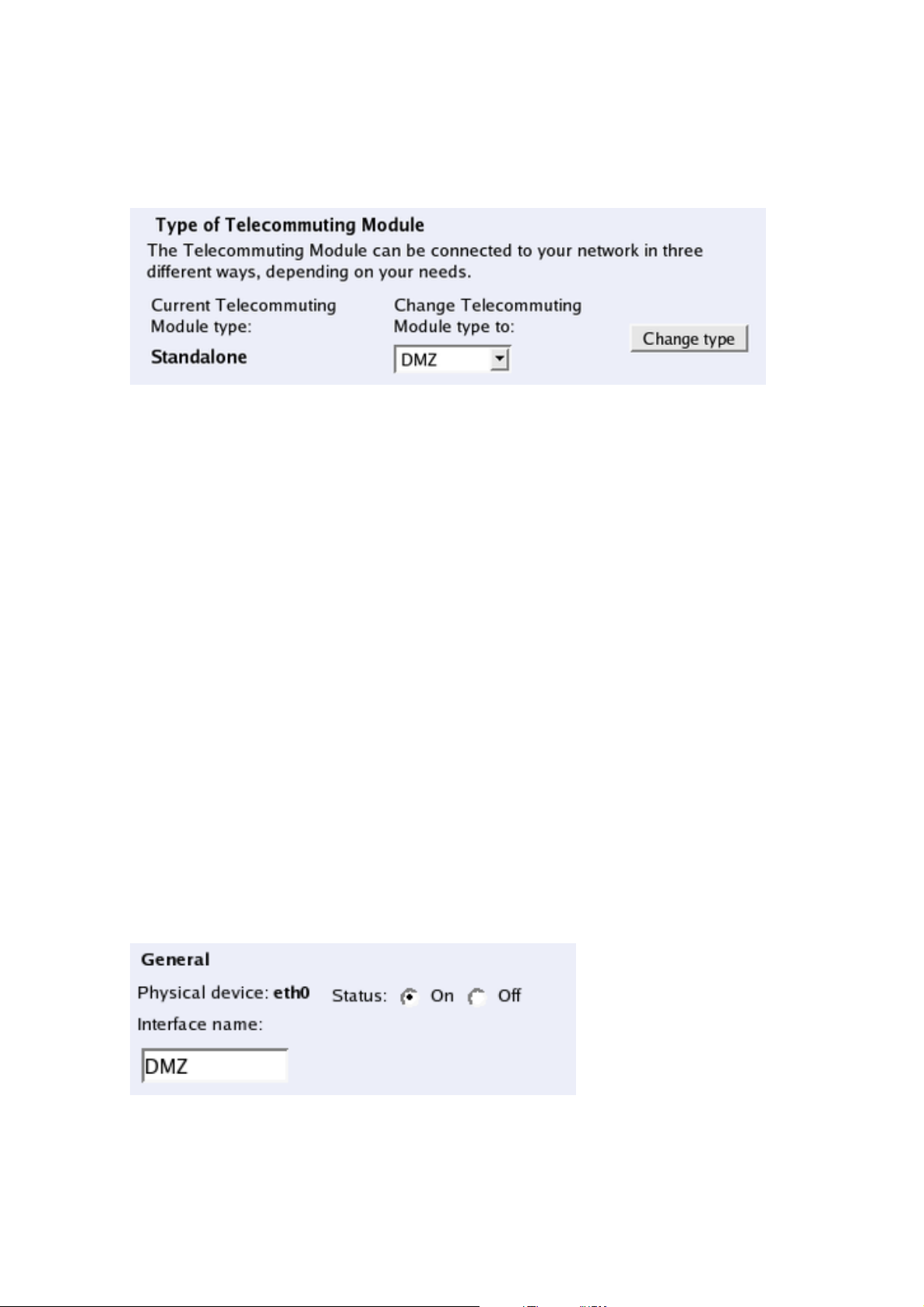
Telecommuting Module Type configuration
Current Telecommuting Module Type
Shows which type is currently active.
Change Telecommuting Module Type to
Select a new Telecommuting Module Type here.
Change type
Press the Change type button to set the new Telecommuting Module Type. This setting,
like others, must be applied on the Save/Load Configuration page before it affects the
Telecommuting Module functionality.
Interface (Network Interface 1 and 2)
There is a page for each network interface (Network Interface 1 and 2) on the Telecommuting
Module. Select a page to make configuration for that interface. There is also a page where
configuration for all interfaces can be viewed and changed.
Here, you set the interface name, whether the interface is on or off, the IP address, alias, and
static routing.
For each interface, go to Directly Connected Networks and state the IP address of the
Telecommuting Module and the size of the network connected to this interface.
General
19
Page 28
Chapter 4. Network Configuration
Physical device
Physical device tells the physical device name of the network interface.
Status
Specify if this network interface is On or Off. If the interface is off, all configuration on
this page is ignored, and the Telecommuting Module will behave as if this interface wasn’t
present.
Interface name
The network Interface name is only used internally in the Telecommuting Module, e. g.
when configuring Networks and Computers.
Obtain IP Address Dynamically
Specify if this network interface should obtain its IP address from a DHCP or PPPoE server
instead of an address entered on this page. If DHCP client ON is selected, the Telecommuting Module will send out a DHCP request when you apply the configuration and at boot. The
request is sent out to the network connected to this interface. If no IP address is obtained,
the Telecommuting Module will keep on sending requests until an address lease is received.
The Telecommuting Module will accept an IP address and a netmask via DHCP. It will also
accept a default gateway, if you configured for that in the Main Default Gateways table on
the Default Gateway page.
If PPPoE client ON is selected, the Telecommuting Module will send out a PPPoE request
when you apply the configuration and at boot. To obtain an IP address via PPPoE, you also
need to enter configuration on the PPPoE page.
More than one interface can obtain its IP address dynamically.
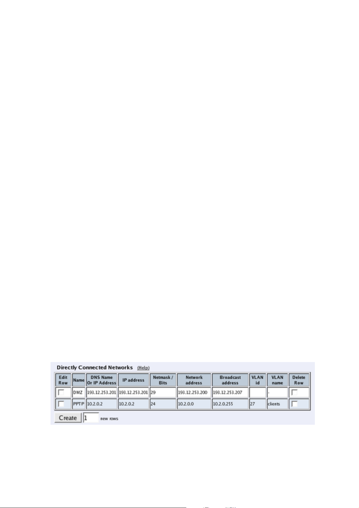
Directly Connected Networks
The Telecommuting Module must have an IP address on every network to which it is directly
connected. This applies to all networks on the same physical network to which this interface
is connected.
When the DHCP client is on, there must be a directly connected network with "*" as the
DNS name/IP address, and where the Netmask/bits field is left empty. No other directly
connected networks are allowed for this interface.
20
Page 29

Chapter 4. Network Configuration
Name
A name for this IP address. You can use this name when configuring VPN. This name is
only used internally in the Telecommuting Module.
DNS Name Or IP Address
The name/IP address of the Telecommuting Module on this network interface on this directly
connected network. If a name is entered, you must enter the IP address for a name server on
the Basic Configuration page.
IP address
Shows the IP address of the DNS Name Or IP Address you entered in the previous field.
Netmask/Bits
Enter the mask of the network where the DNS Name Or IP Address applies.
Network address
The IP address of the network where the DNS Name Or IP Address applies.
Broadcast address
Shows the broadcast address of the network in the Network address field.
VLAN Id
VLANs are used for clustering IP ranges into logical networks. A VLAN id is simply a
number, which identifies the VLAN uniquely within your network.
Enter a VLAN id for this network. You don’t need to use a named VLAN (defined on the
VLAN page).
VLAN Name
If you entered the VLAN id of a named VLAN, the name will show here.
Delete Row
If you select this box, the row is deleted when you click on Create new rows, Save, or Look
up all IP addresses again.
Create
Enter the number of new rows you want to add to the table, and then click on Create.
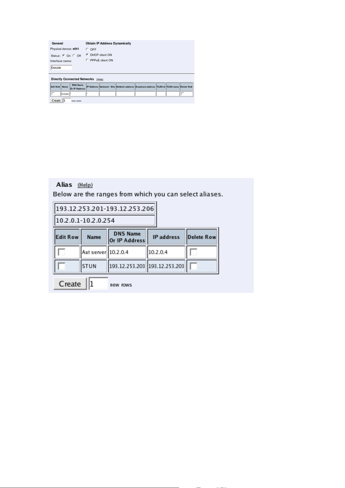
If the interface should obtain its IP address from a DHCP server, the settings should be like
in the image below. With a DHCP IP, no aliases can be defined for the interface.
21
Page 30
Chapter 4. Network Configuration
Alias
3Com VCX IP Telecommuting Module can use extra IP addresses, aliases, on its interfaces.
All alias IP addresses must belong to one of the Directly Connected Networks you have
specified.
Aliases are necessary for setting up a STUN server.
If the interface obtains its IP address dynamically, no aliases can be defined.
Name
Enter the name of your alias. This name is only used internally in the Telecommuting Module.
DNS Name Or IP Address
Enter the IP address of this alias, or a name in the DNS. If you enter a DNS name instead of
an IP address, you must enter the IP address of a DNS server on the Basic Configuration
page.
IP address
Shows the IP address of the DNS Name Or IP Address you entered in the previous field.
22
Page 31
Chapter 4. Network Configuration
Delete Row
If you select this box, the row is deleted when you click on Create new rows, Save, or Look
up all IP addresses again.
Create
Enter the number of new rows you want to add to the table, and then click on Create.
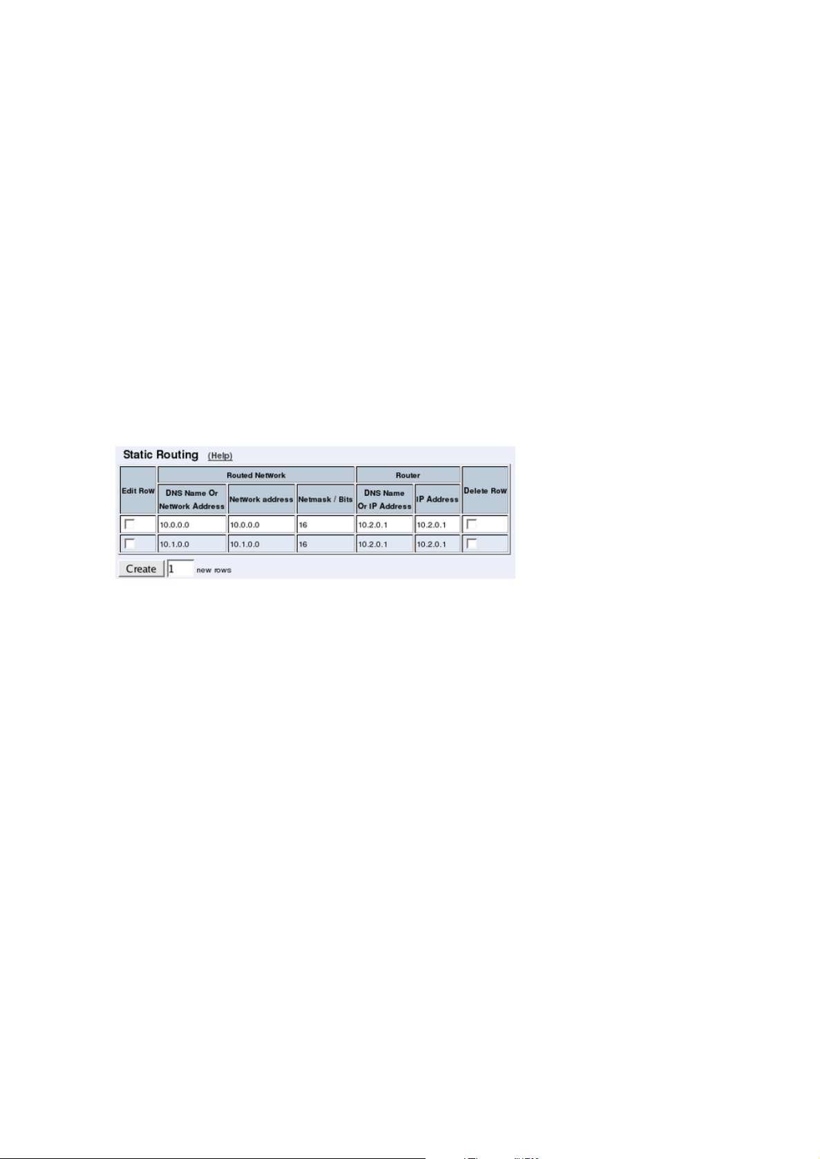
Static Routing
If there is a router between the Telecommuting Module and a computer network which the
Telecommuting Module is serving, you must name the router and the network here. The
table is sorted by network number and network mask.
The Default gateway, configured on the Default Gateway page, will automatically be entered in this table on the corresponding interface page, when added to the Main Default
Gateways table.
If the interface obtains its IP address dynamically, no other static routes can be defined.
Routed network
Enter the DNS name or IP address of the routed network under DNS Name Or Network
Address.
The IP address of the routed network is shown under Network address.
In the Netmask/Bits field, enter the netmask of the network.
Router
The name or IP address of the router that will be used for routing to the network. If there
are several routers between the Telecommuting Module and the network, fill in the router
closest to the Telecommuting Module.
If an interface will receive its IP address from a DHCP server, the Telecommuting Module
will get its default gateway from the server. In this case, select the corresponding IP address
under Dynamic.
Delete Row
If you select this box, the row is deleted when you click on Create new rows, Save, or Look
up all IP addresses again.
23
Page 32

Chapter 4. Network Configuration
Create
Enter the number of new rows you want to add to the table, and then click on Create.
Save
Saves all Interface configuration to the preliminary configuration.
Cancel
Clears and resets all fields in new rows and resets changes in old rows.
Look up all IP addresses again
Looks up the IP addresses for all DNS names on this page in the DNS servers you entered
on the Basic Configuration page.
This button will only be visible if a DNS server has been configured.
Default Gateway
Main Default Gateways
The Default gateway is the IP address of the router that is used to contact the outside world.
This IP address is usually the firewall. Default gateway must be an IP address from one of
the Directly Connected Networks of the Telecommuting Module’s interfaces. See appendix
C of the User Manual, for further description of routers/gateways.
The Telecommuting Module must have at least one default gateway to work.
You can enter more than one default gateway. The Telecommuting Module will use one of
them until it stops responding, and then switch to the next one.
Priority
If you entered more than one default gateway, you can assign a priority to each of them.
The Telecommuting Module will use the gateway with the highest priority (lowest number)
when it works. If it stops working, the Telecommuting Module will switch to the next in
priority, while checking the first for availability. When the first gateway works again, the
Telecommuting Module will switch back to using that.
24
Page 33

Chapter 4. Network Configuration
Dynamic
If an interface will receive its IP address from a DHCP server, the Telecommuting Module
will get its default gateway from the server. In this case, select the corresponding IP address
here.
DNS Name Or IP Address
Enter the DNS name or IP address for the default gateway. If an interface will receive its IP
address from a DHCP server, the Telecommuting Module will get its default gateway from
the server. In this case, leave this field empty.
IP address
Shows the IP address of the DNS Name Or IP Address you entered in the previous field.
Interface
Select the interface connected to the Telecommuting Module default gateway.
Delete Row
If you select this box, the row is deleted when you click on Create new rows, Save, or Look
up all IP addresses again.
Create
Enter the number of new rows you want to add to the table, and then click on Create.
Policy For Packets From Unused Gateways
This policy controls how packets from the currently unused gateway(s) should be treated.
The packet can be allowed (subject to the rest of the configuration) or discarded.
The Discard IP packets selection means that the Telecommuting Module ignores the IP
packets without replying that the packet did not arrive.
The Allow IP packets selection makes the Telecommuting Module use the rest of the configuration to decide if the packet should be allowed.
Gateway Reference Hosts
The gateway reference hosts are used by the Telecommuting Module to check if the gateways
are alive. For each reference host, test ping packets are sent, using the different gateways.
Reference hosts are not needed if you have entered a single default gateway.
25
Page 34

Chapter 4. Network Configuration
DNS Name Or IP Address
Enter the DNS name or IP address for the reference host. The reference host must be located
on the other side of the default gateway.
IP address
Shows the IP address of the DNS Name Or IP Address you entered in the previous field.
Delete Row
If you select this box, the row is deleted when you click on Create new rows, Save, or Look
up all IP addresses again.
Create
Enter the number of new rows you want to add to the table, and then click on Create.
Save
Saves the Default Gateway configuration to the preliminary configuration.
Cancel
Clears and resets all fields in new rows and reset changes in old rows.
Networks and Computers
Here, you name groups of computers and networks. Sometimes it can be useful to give a
group of computers a network name, such as Administration. If you want to group some
computers, this can be done here, even if they do not have consecutive IP addresses. You can
also include a subgroup when defining a new network group.
The names are used when you configure Surroundings, Filtering and Local Registrar.
Every group of computers which can reach each other without having to pass through the
firewall needs a separate network group.
The rows are sorted in alphabetical order, except that all upper case letters are sorted before
lower case letters (B comes before a).
When using an already defined group as a subgroup, select the name of the group under
Subgroup. Set Interface/VLAN to ’-’ and leave the other fields empty.
26
Page 35

Chapter 4. Network Configuration
Name
Enter a name for the group of computers. You can use this name when you change configuration on the pages mentioned above. A group can consist of several rows of IP addresses
or series of IP addresses. By clicking on the plus sign beside the name, you add more rows
where you can specify more IP addresses for this group.
Subgroup
An already defined group can be used as a subgroup to new groups. Select the old group
here and leave the fields for DNS name empty. Select ’-’ as Interface. If you don’t want to
use a subgroup, select ’-’ here.
Lower Limit
DNS Name Or IP Address
Enter the DNS name or IP address of the network or computer. For computers in an IP range
that you want to give a network name, enter the first IP address in the range. DNS Name Or
IP Address must not be empty if you are not using a subgroup.
IP address
The IP address of the object you entered in the DNS Name Or IP Address field is displayed
here. This field is not updated until you click on Look up all IP addresses again or make
changes in the DNS Name Or IP Address field.
27
Page 36

Chapter 4. Network Configuration
Upper Limit
DNS Name Or IP Address
Here, enter the last DNS name/IP address of the network or group. For computers in an IP
range that you want to give a network name, enter the last IP address in the seriesrange. The
IP address in Upper Limit must be at least as high as the one in Lower Limit. If this field
is left empty, only the IP address in Lower Limit is used. If you use a subgroup, leave this
field empty.
IP address
The IP address of the object you entered in the DNS Name Or IP Address field is displayed
here. This field is not updated until you click on Look up all IP addresses again or make
changes in the DNS Name Or IP Address field.
Interface/VLAN
Here, you can select an interface or a VLAN to restrict the IP range.
If ’-’ is chosen, the group will consist of all IP addresses in the interval between Lower
Limit and Upper Limit, regardless of what interface they are connected to. By selecting
an interface or a VLAN, you constrain the group to consist only of the IP addresses in the
interval that really are connected to the selected interface/VLAN.
For example, if 10.20.0.0 - 10.20.0.255 are IP addresses behind the interface DMZ-1 and the
lower and upper limits are 10.10.10.20 and 255.255.255.255 respectively, choosing DMZ-1
as Interface will cause the group to consist of the IP addresses 10.20.0.0 - 10.20.0.255, being
the IP addresses in the interval actually connected to the selected interface.
If you have selected a subgroup, the Interface/VLAN should be ’-’. If you want to define a
network group at the remote side of a VPN connection, the Interface/VLAN should be ’-’.
Delete Row
If you select this box, the row is deleted when you click on Create new rows, Save, or Look
up all IP addresses again.
Create
Enter the number of new groups and rows you want to add to the table, and then click on
Create.
Save
Saves the Networks and Computers configuration to the preliminary configuration.
Cancel
Clears and resets all fields in new rows and reset changes in old rows.
28
Page 37

Chapter 4. Network Configuration
Surroundings
State the topology around the Telecommuting Module on this page. Which type of topology
is needed depends on which Telecommuting Module Type was selected.
Surroundings
Settings in the Surroundings table are only required when the Telecommuting Module has
been made the DMZ (or LAN) type.
The Telecommuting Module must know what the networks around it looks like. On this
page, you list all networks which the Telecommuting Module should serve and which are
not reached through the default gateway of the firewall.
All computers that can reach each other without having to go through the firewall connected
to the Telecommuting Module should be grouped in one network. When you are finished,
there should be one line for each of your firewall’s network connections (not counting the
default gateway).
One effect of this is that traffic between two users on different networks, or between one of
the listed networks and a network not listed here, is NAT:ed.
Another effect is that for connections between two users on the same network, or on networks where neither is listed in Surroundings, no ports for RTP sessions will be opened,
since the Telecommuting Module assumes that they are both on the same side of the firewall.
For DMZ and LAN SIParators, at least one network should be listed here. If no networks
are listed, the Telecommuting Module will not perform NAT for any traffic.
Network
Select a network. The alternatives are the networks you defined on the Networks and Computers page.
Additional Negotiators
Sometimes you have SIP devices on a different network that needs to negotiate for this
network. This happens when there is a SIP server on one network, and SIP-unaware phones
on another. In this case, select the phone network under Network, and the SIP server as an
Additional Negotiator. Select from the networks defined on the Networks and Computers
page.
29
Page 38

Chapter 4. Network Configuration
Delete Row
If you select this box, the row is deleted when you click on Create new rows or Save.
Create
Enter the number of new rows you want to add to the table, and then click on Create.
Data Interfaces
Settings in the Data Interfaces table are only required when the Telecommuting Module
has been made the WAN type.
Between the Data Interfaces listed here, the Telecommuting Module will act as a plain router,
and only forward traffic, with the exception that QoS will be performed if configured for the
traffic in question.
The traffic sent between Data Interfaces will not be logged by the Telecommuting Module.
The Telecommuting Module will only send SIP traffic between the other interfaces.
Interface
Select a data interface here.
Delete Row
If you select this box, the row is deleted when you click on Create new rows or Save.
Create
Enter the number of new rows you want to add to the table, and then click on Create.
Save
Saves all Surroundings configuration to the preliminary configuration.
Cancel
Clears and resets all fields in new rows and resets changes in old rows.
30
Page 39

Chapter 4. Network Configuration
Basic Configuration
On the Basic Configuration page, general settings for the Telecommuting Module are made.
The most important one for getting started is the DNS server.
General
Name of this Telecommuting Module
Here, you can give your 3Com VCX IP Telecommuting Module a name. The name of the
Telecommuting Module is displayed in the title bar of your web browser. This can be a good
idea if you administer several Telecommuting Modules. The name is also used if you use
SNMP and when you export log files into the WELF format.
Default domain
Here, you can enter a default domain for all settings. If a default domain is entered, the Telecommuting Module will automatically assume that an incomplete computer
name should be completed with the default. If, for example, Default domain contains
company.com, you could as the name of the computer axel.company.com use only axel.
If no default domain should be used, the Default domain field should contain a single dot
(.).
IP Policy
Here, you specify what will happen to IP packets which are neither SIP packets, SIP session
media streams, or Telecommuting Module administration traffic. Discard IP packets means
that the Telecommuting Module ignores the IP packets without replying that the packet did
not arrive. Reject IP packets makes the Telecommuting Module reply with an ICMP packet
telling that the packet did not arrive.
Policy For Ping To Your 3Com VCX IP Telecommuting Module
Here, you specify how the Telecommuting Module should reply to ping packets to its IP
addresses. You can choose between Never reply to ping, Only reply to ping from the
same interface and Reply to ping to all IP addresses. Only reply to ping from the same
interface means that the ping request should originate from a network which is directly-
connected to the pinged interface of the Telecommuting Module or from a network to which
there exists a static route from the pinged interface, or the request will be ignored.
31
Page 40

Chapter 4. Network Configuration
Ping is a way of finding out whether a computer is working. See appendix C of the User
Manual for further information on ping.
DNS Servers
Here, you configure DNS servers for the Telecommuting Module. The servers are used in
the order they appear in this table, which means that the Telecommuting Module uses the
top server to resolve DNS records until it doesn’t reply. Only then is server number two
contacted.
No.
The DNS servers are used in the order they are presented in the table. To move a server to
a certain row, enter the number on the row to which you want to move it. You need only
renumber servers that you want to move; other servers are renumbered automatically. When
you click on Save, the DNS servers are re-sorted.
Dynamic
If an interface will receive its IP address from a DHCP server, the Telecommuting Module can also get information about its DNS server from that server. In this case, select the
corresponding IP address here and leave the other fields empty.
DNS Name Or IP Address
The DNS name/IP address of the DNS server which the Telecommuting Module should use.
Note that to use DNS names here, there must exist a DNS server in the Telecommuting
Module’s permanent configuration.
IP address
Shows the IP address of the DNS Name Or IP Address you entered in the previous field.
Delete Row
If you select this box, the row is deleted when you click on Create new rows, Save, or Look
up all IP addresses again.
Create
Enter the number of new rows you want to add to the table, and then click on Create.
32
Page 41

Chapter 4. Network Configuration
Save
Saves the Basic Configuration configuration to the preliminary configuration.
Cancel
Reverts all the above fields to their previous configuration.
Look up all IP addresses again
Looks up the IP addresses for all DNS names on this page in the DNS servers you entered
above.
33
Page 42

Chapter 4. Network Configuration
34
Page 43
Chapter 5. SIP Configuration
SIP (Session Initiation Protocol) is a protocol for creating and terminating various media
stream sessions over an IP network. It is for example used for Internet telephone calls and
distribution of video streams.
SIP takes care of the initiation, modification and termination of a session with one or more
participants. The protocol makes it possible for the participants to agree on what media
types they should share. You can find more information about SIP in appendix A of the User
Manual and in RFC 3261.
Basic SIP configuration is made on the Basic Settings, Local Registrar, and possibly also
Sessions and Media pages. If you want to use an external SIP proxy, you must state this on
the Routing page.
Basic Settings
Here, you make basic settings for the Telecommuting Module SIP management.
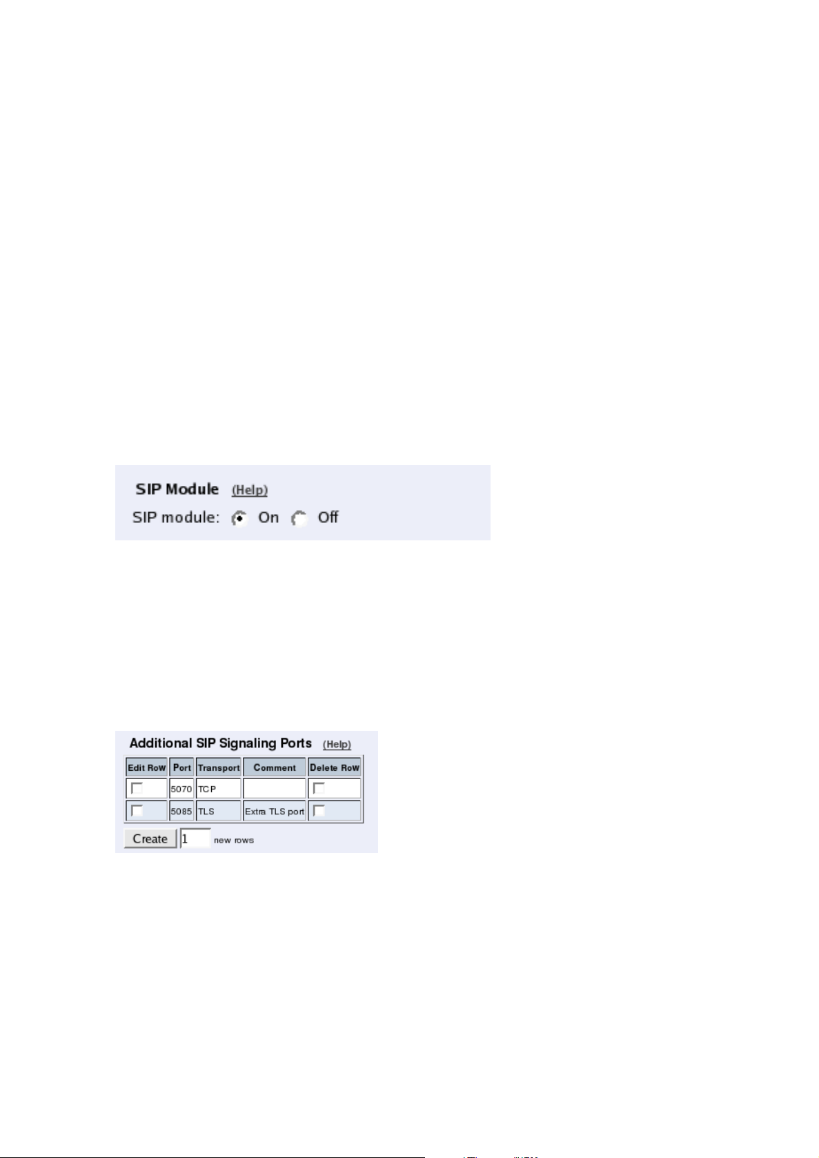
SIP Module
Here, select whether the SIP module should be enabled or disabled. If you select to Disable
SIP module, no other SIP settings will have any effect.
Additional SIP Signaling Ports
Normally, the Telecommuting Module listens for SIP signaling on ports 5060 (UDP and
TCP) and 5061 (TLS). You can make it listen for SIP signaling on additional ports. When
ports are added here, they are reserved for SIP signaling on all the Telecommuting Module
IP addresses.
Port
Enter an additional port on which the Telecommuting Module should listen for SIP signaling. The Telecommuting Module will then receive SIP signaling on this port for all its IP
addresses.
SIP signaling over TLS cannot be received on a Telecommuting Module port which is used
for something else, like configuration of the Telecommuting Module.
35
Page 44

Chapter 5. SIP Configuration
Transport
Select which SIP signaling transports should be allowed on this port.
Comment
Enter a comment to remind yourself why you added the port.
Delete Row
If you select this box, the row is deleted when you click on Create new rows or Save.
Create
Enter the number of new rows you want to add to the table, and then click on Create.
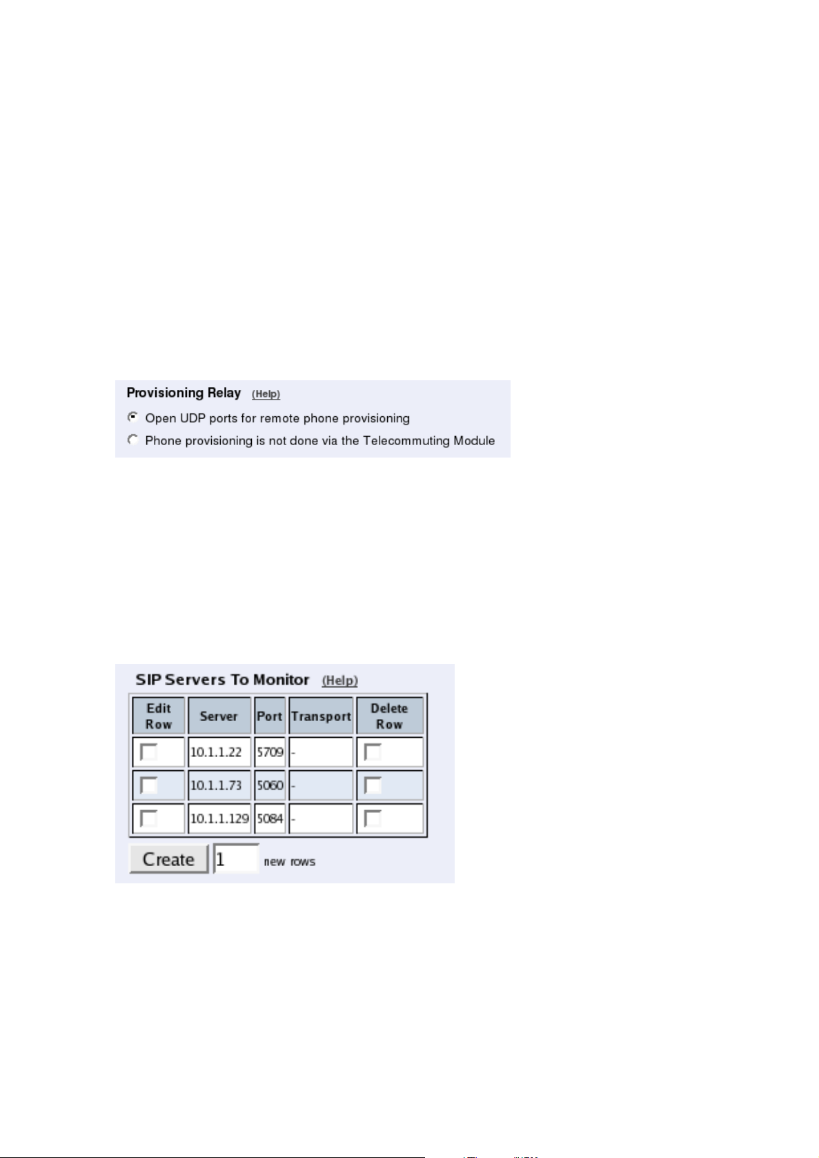
Provisioning Relay
Remote phones usually need to access your PBX for provisioning. For many phones, the
provisioning server is the same as their registrar, which means that it is the IP address of
the Telecommuting Module. To enable provisioning, the Telecommuting Module can open
ports for this traffic.
Select if the Telecommuting Module should open ports for provisioning traffic, or if the
phones get their settings in another way.
SIP Media Port Range
State a port interval which the Telecommuting Module should use for SIP media streams.
You can use any high ports except 4500 (reserved for NAT-T) and 65097-65200 (reserved
for RADIUS).
Note! A change in the port interval will make the SIP module restart when the configuration
change is applied.
When the SIP module is restarted, all active SIP sessions (SIP calls, video conferences etc)
will be torn down and all SIP user registrations will be removed.
Enter the lower and upper limit of the port range that the Telecommuting Module should use
for media streams. The upper limit must be at least as high as the lower limit.
36
Page 45
Chapter 5. SIP Configuration
Public IP address for NATed Telecommuting Module
Sometimes, the Telecommuting Module is located behind a NAT box that is not SIP-aware.
This will make signaling go awry, with the result that in many cases there will be voice in
only one direction.
This can be corrected by entering the public IP address that the Telecommuting Module will
appear to have. When sending SIP signaling towards its default gateway, the Telecommuting
Module will use that IP address instead of its private one, which will get media to the right
place.
Note that the NATing device must also be configured to forward SIP signaling on that IP
address to the Telecommuting Module.
If nothing is entered here, the Telecommuting Module will use its own IP addresses.
This setting is not supported for the Standalone configuration.
SIP Servers To Monitor
Your Telecommuting Module can be made to monitor SIP servers, to check that they are
alive. The information is used by the Telecommuting Module when SIP signaling should
be passed on to the server in question. This is useful when a domain resolves to several
individual hosts; the Telecommuting Module will know immediately if one of them is down,
which will speed up the call connection.
The SIP server must respond with a SIP packet to OPTIONS packets to be monitored in this
way.
Server
Enter the host name, domain name, or IP address of the server to be monitored.
Port
Enter the port to be monitored on that host. This should be the port to use for SIP signaling.
37
Page 46
Chapter 5. SIP Configuration
Transport
Select the transport to be monitored on that host. This should be the transport to use for SIP
signaling.
Delete Row
If you select this box, the row is deleted when you click on Create new rows or Save.
Create
Enter the number of new rows you want to add to the table, and then click on Create.
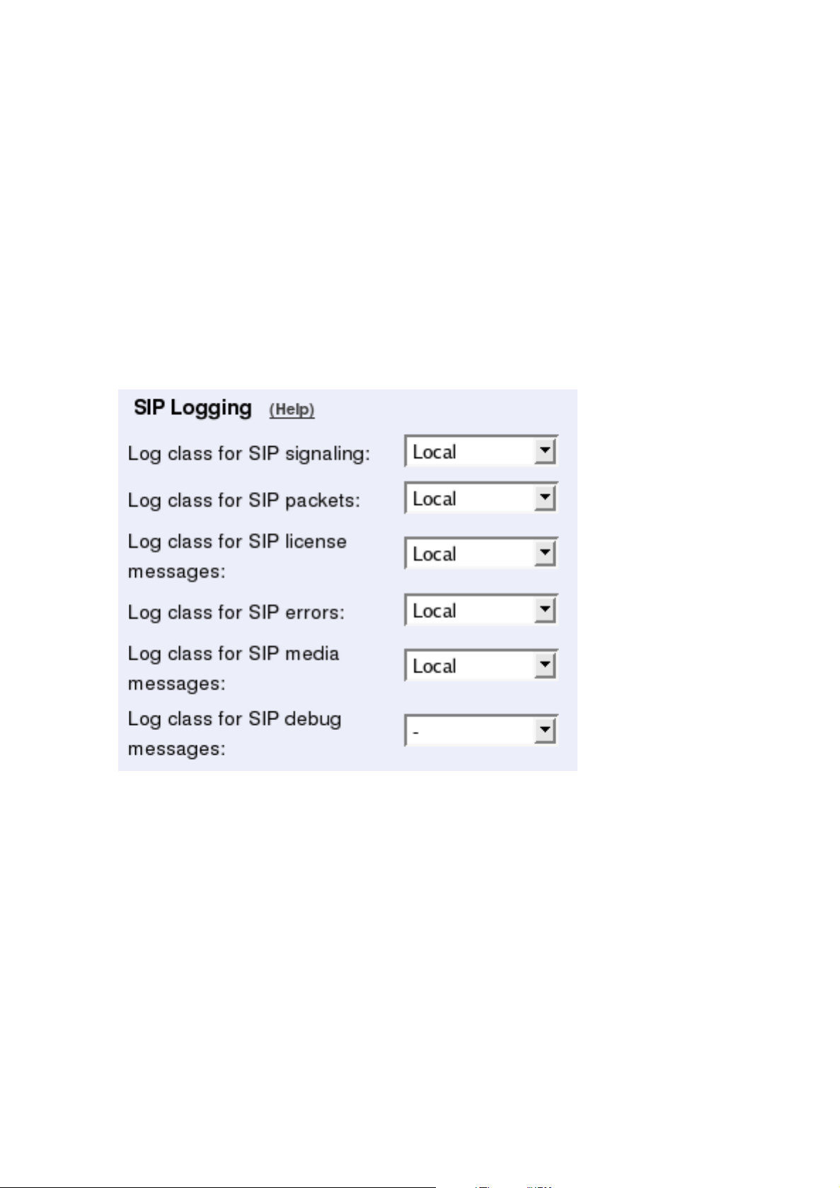
SIP Logging
The same settings can also be found on the Logging Configuration page under Logging.
Log class for SIP signaling
For each SIP packet, the Telecommuting Module generates a message, containing the sender
and receiver of the packet and what type of packet it is. Select a log class for these log
messages.
Log class for SIP packets
The Telecommuting Module logs all SIP packets (one SIP packet is many lines). Select a
log class for the SIP packets.
Log class for SIP license messages
The Telecommuting Module logs license messages. Select a log class for these messages.
38
Page 47

Chapter 5. SIP Configuration
Log class for SIP errors
The Telecommuting Module sends a message if there are any SIP errors. Select a log class
for these log messages.
Log class for SIP media messages
The Telecommuting Module creates log messages about when media streams are set up and
torn down. Select a log class for these messages.
Log class for SIP debug messages
The Telecommuting Module logs a lot of status messages, for example the SIP initiation
phase of a reboot. Select a log class for these messages.
Save
Saves the Basic Settings configuration to the preliminary configuration.
Cancel
Clears and resets all fields in new rows and resets changes in old rows.
Routing
DNS Override For SIP Requests
Here, you can register SIP domains to which the Telecommuting Module should be able to
forward requests, but which for some reason cannot be resolved in DNS. Enter an IP address
and port to which the requests should be forwarded. You can also select to use a specific
protocol.
The Telecommuting Module uses the Request-URI of the incoming SIP packet to match for
the domains in this table. When it matches a domain, the packet will be forwarded to the IP
address entered here. Note that the Request-URI will not be rewritten!
You can also enter subdomains to Local SIP Domains, if you want the subdomain to be
handled by a separate SIP proxy. This table has a higher priority than Local SIP Domains,
which means that if you register a subdomain to a domain registered under Local SIP Do-
mains, the Telecommuting Module will forward SIP requests to the subdomain instead of
processing them itself.
You can enter more than one IP address or host name for a domain, and set weights and
priorities for these.
39
Page 48

Chapter 5. SIP Configuration
Domain
Enter the domain name of the SIP domain. This domain is compared to the domain in the
Request-URI of the incoming SIP packet.
You can’t enter a domain that was entered in the Local SIP Domains table.
Relay To
DNS Name Or IP Address
Enter the IP address for the SIP server handling the domain. You can also enter a DNS
name for the SIP server, if it has a DNS-resolvable host name, even if the SIP domain is not
possible to look up in DNS.
IP address
Shows the IP address of the DNS Name Or IP Address you entered in the previous field.
Port
Here, enter the port on which the SIP server listens for SIP traffic. The standard port is 5060
(5061 for TLS).
Transport
You can select which transport protocol to use between the Telecommuting Module and the
SIP server. Under Transport, select from UDP, TCP and TLS.
Priority
If you entered more than one IP address/host name for the same domain, you should also
assign them Priority and Weight. A low Priority value means that the unit should have a
high priority.
Weight
If more than one unit has the same Priority, the signaling sent to them is distributed between
them according to their Weight. If two units have the same priority, and Unit 1 has weight
4, and Unit 2 has weight 9, 4/13 of the signaling will be sent to Unit 1, and 9/13 will be sent
to Unit 2.
40
Page 49

Chapter 5. SIP Configuration
Delete Row
If you select this box, the row is deleted when you click on Create new rows, Save, or Look
up all IP addresses again.
Create
Enter the number of new groups and rows you want to add to the table, and then click on
Create.
Filtering
On the Filtering page you select the MIME types you want to let through, if the Telecommuting Module should forward any other SIP traffic than just IP telephony or instant messages.
On that page, you can also select filtering of SIP signaling based on several conditions.
Sender IP Filter Rules
Here, you set all the rules for SIP requests from different networks. Requests that do not
match any rule are handled according to the Default Policy For SIP Requests.
No.
The No. field determines the order of the rules. Rules are used in the order in which they are
displayed in the table; rule number 1 is first. The order is important if you used networks
which partly contain the same IP addresses. To change order for a rule, enter the new number
in the field and press Save.
From Network
The network name that the SIP request originates from. You can select between the networks
defined on the Networks and Computers page under Network Configuration.
Action
Under Action, you select what to do with a SIP request from the selected network. The
choices are Process all, which handles all requests regardless of destination, Local only,
which only handles requests to Local SIP Domains (entered on the Local Registrar page),
and Reject all, which doesn’t handle any requests at all.
41
Page 50

Chapter 5. SIP Configuration
Delete Row
If you select this box, the row is deleted when you click on Create new rows or Save.
Create
Enter the number of new rows you want to add to the table, and then click on Create.
Default Policy For SIP Requests
Select what to do with SIP requests that do not match any of the Proxy Rules. The choices
are Process all, which handles all requests regardless of destination, Local only, which only
handles requests to Local SIP Domains (entered on the Local Registrar page), and Reject
all, which doesn’t handle any requests at all.
Content Types
The SIP packets present information in different ways, using content types (MIME types).
Enter here which types the SIP proxy should accept. The most common MIME types are
predefined and you only have to activate them.
The content types application/sdp (used for SIP requests), application/xpidf+xml (used for
Presence) and text/x-msmsgsinvite (used by Messenger) are always accepted - you don’t have
to enter them into the table. You can find a complete list of MIME types at ftp://ftp.isi.edu/innotes/iana/assignments/media-types/media-types/.
Content Type
Enter the content type (only one in each row). The format is category/type, e.g.
text/plain. You can also allow all content types by entering*/*in a row and allow
it.
42
Page 51

Chapter 5. SIP Configuration
Allow
Select if the Telecommuting Module should allow (On) or reject (Off) this content type in
SIP signaling.
Delete Row
If you select this box, the row is deleted when you click on Create new rows or Save.
Create
Enter the number of new rows you want to add to the table, and then click on Create.
Interoperability
URI Encoding
When registering a SIP client on one side of the Telecommuting Module to a SIP server
on the other side, the Contact header is normally encrypted and rewritten. By doing this,
we make it possible for the SIP server to track when the same user is sending requests
from different places. It is possible to turn encryption and rewriting off, and to shorten the
encrypted URI in Contact headers passing through the Telecommuting Module.
Select what to do with Contact headers.
Always encrypt URIs will make the Telecommuting Module encrypt the entire Contact
header URI.
Use shorter, encrypted URIs will make the Telecommuting Module generate a random
string for the incoming Contact URI. This will then be used as the username part of the
outgoing Contact header URI.
When you select this, the Telecommuting Module makes no checks of incoming SIP URIs.
It becomes possible in theory to trick the Telecommuting Module to send SIP packets anywhere, so security is drastically reduced.
Escape URIs will make the Telecommuting Module escape the entire original URI and use
that as the username part of the outgoing Contact.
The encryption of a Contact URI is changed when the Call-ID changes, when the client gets
a new IP address, or when the user changes its Contact URI.
43
Page 52

Chapter 5. SIP Configuration
When you select this, the Telecommuting Module makes no checks of incoming SIP URIs.
It becomes possible in theory to trick the Telecommuting Module to send SIP packets anywhere, so security is drastically reduced.
Keep username in URIs will make the Telecommuting Module keep the original username
pare of the Contact URI, and only replace the domain part.
When you select this, it will be impossible for the remote SIP server to tell if requests
for a certain user belong to one or several clients, as it has no means of telling the client
registrations for a user apart. This means that if a user registers from two clients, and then
unregisters from one of them, the SIP server will remove its only registration record for that
user.
The Telecommuting Module also makes no checks of incoming SIP URIs. It becomes possible in theory to trick the Telecommuting Module to send SIP packets anywhere, so security
is drastically reduced.
Remote SIP Connectivity
Remote NAT Traversal
If your SIP client is not STUN-capable, you can use the built-in Remote NAT traversal feature of the Telecommuting Module. The client must register on the Telecommuting Module
(or through it).
The SIP client needs to re-REGISTER, or respond to OPTIONS packets, rather often for this
to work. The exact period for this depends on the NAT-ing device, but 20 seconds should be
enough to get across most NAT boxes.
Remote NAT traversal
Switch this function on or off.
Remote Clients Signaling Forwarding
Many SIP servers need to separate signaling to and from remote clients from signaling to
and from the SIP Trunk. For this purpose, you can specify which IP address and port the
remote clients will connect to. This can’t be the same IP address and port as what the SIP
provider uses!
44
Page 53

Chapter 5. SIP Configuration
You also specify which IP address the Telecommuting Module will use when it forwards this
SIP signaling to the server on the LAN. In this way, the trunk signaling and remote client
signaling will be separated for the PBX.
IP Address for Remote Clients
Select which IP address remote clients connect to. This can be the same IP address as is used
by the SIP provider, but then you need to select a different signaling port below.
IP Port for Remote Clients
Enter the signaling port to which remote SIP clients should connect. The Telecommuting
Module will listen for SIP signaling on this port only for the IP address selected above.
If you select an alias IP address as the address to where remote clients should connect, you
can’t enter a port, but must use port 5060 (5061 for TLS connections). If you select an IP
address that was entered in the Directly Connected Networks table, you must specify a
port.
You cannot select a port that is already in use for something else, or specified in the Addi-
tional SIP Signaling Ports table.
Forward Signaling from IP Address
Select which IP address the Telecommuting Module should use as the sender IP address
when forwarding signaling from remote clients.
As all other SIP signaling will be forwarded using the IP address entered in the Directly
Connected Networks, you must select an Alias IP address here.
NAT keepalive method
Clients using this function will have to send SIP packets very often, to keep the IP/port NAT
binding. Select which method to use to force the clients to send packets frequently.
OPTIONS are sent from the Telecommuting Module to the client, and the client is required
to respond to these OPTIONS packets to keep the NAT binding.
With short registration times, the Telecommuting Module tells the client to register with
shorter intervals than it normally should have used, to keep the NAT binding. This will load
the SIP registrar as well (if the Telecommuting Module is not the registrar), but is a method
supported by all SIP clients.
NAT timeout for UDP
Enter the timeout the NAT box uses for UDP connections. The Telecommuting Module uses
this information when deciding the intervals with which to send OPTIONS or tell the client
to re-register.
NAT timeout for TCP
Enter the timeout the NAT box uses for TCP connections. The Telecommuting Module uses
this information when deciding the intervals with which to send OPTIONS or tell the client
to re-register.
45
Page 54

Chapter 5. SIP Configuration
Media Route
Usually, media is always sent via the Telecommuting Module when the Remote NAT Traversal feature is used. For clients behind the same NAT, media can be made to go directly
between the clients, to lower the Telecommuting Module and network load.
46
Page 55

Chapter 6. Administration of the Telecommuting Module
You also need to configure who can access the Telecommuting Module web interface. This
is done on the Access Control page under Basic Configuration.
Remember that the configuration you see in the web interface (preliminary configuration)
isn’t necessarily the work configuration (permanent configuration) of the Telecommuting
Module. When all configuration is made in the web interface, it must be applied. This is
done on the Save/Load Configuration page under Administration.
Access Control
On the Access Control page, settings are made which controls the access to the Telecommuting Module administration interfaces. The Telecommuting Module can be configured
via the web (http and https) and via ssh or the serial cable (using the CLI, see chapter 18 of
the Reference Guide).
Select one or more configuration IP addresses for the Telecommuting Module. The configuration address is the IP address to which you direct your web browser to access the web
interface of the Telecommuting Module, or connect your ssh client to.
For each network interface, you also specify whether or not the Telecommuting Module can
be configured via this network interface.
You also select what kind of authentication will be performed for the users trying to access
the administration interfaces.
To further increase security, the Telecommuting Module can only be configured from one
or a few computers that are accessed from one of these interfaces. Enter the IP address or
addresses that can configure the Telecommuting Module. The IP addresses can belong to one
or more computers. For each IP address or interval of addresses, select which configuration
protocols are allowed.
Configuration Allowed Via Interface
This setting specifies whether configuration traffic is allowed via this interface. If you only
allow configuration via eth1, configuration traffic will only be allowed from computers connected to the eth1 interface, regardless of which IP address the configuration traffic is directed to or which IP addresses the computers have.
The choices for each interface are On and Off. This configuration is a complement to the
Configuration Computers setting below.
47
Page 56

Chapter 6. Administration of the Telecommuting Module
User Authentication For Web Interface Access
Select the mode of administrator authentication for logins via the web interface: Local users,
via a RADIUS database, or a choice between the two alternatives at login (Local users or
RADIUS database).
Local administrator users and their passwords are defined on the User Administration page
under Administration. If the authentication should be made by help of a RADIUS server,
you must enter one on the RADIUS page.
When connecting to the administration interface via SSH, you can only log in as admin.
Configuration Transport
Select Telecommuting Module IP addresses for the allowed configuration protocols. The
Telecommuting Module web server will listen for web traffic on the IP addresses and ports
selected under HTTP and HTTPS.
This is the IP address and port which should be entered in your web browser to connect to
the Telecommuting Module.
For configuration via ssh, you need an ssh client to log on to the Telecommuting Module.
48
Page 57

Chapter 6. Administration of the Telecommuting Module
Configuration via HTTP
Select which IP address and port the Telecommuting Module administrator should direct
her web browser to when HTTP is used for Telecommuting Module configuration. You
can select from the Telecommuting Module IP addresses configured on the Interface pages
under Network Configuration.
You can use different IP addresses for HTTP, HTTPS, and SSH configuration.
Configuration via HTTPS
Select which IP address and port the Telecommuting Module administrator should direct
her web browser to when HTTPS is used for Telecommuting Module configuration. You
can select from the Telecommuting Module IP addresses configured on the Interface pages
under Network Configuration.
You can use different IP addresses for HTTP, HTTPS, and SSH configuration.
You also need to select an X.509 certificate, which works as an ID card, identifying the
Telecommuting Module to your web browser. This will ensure that you are really communicating with your Telecommuting Module and not somebody else’s computer. HTTPS uses
an encryption method using two keys, one secret and one public. The secret key is kept in
the Telecommuting Module and the public key is used in the certificate. If any of the keys is
changed, the HTTPS connection won’t work.
All local certificates for the Telecommuting Module are created on the Certificates page
under Basic Configuration.
Configuration via SSH
Select which IP address and port the Telecommuting Module administrator should direct
her ssh client to when SSH is used for Telecommuting Module configuration. You can select from the Telecommuting Module IP addresses configured on the Interface pages under
Network Configuration.
For SSH configuration, the Command Language Interface is used. See also chapter 18 of the
Reference Guide.
You can use different IP addresses for HTTP, HTTPS, and SSH configuration.
Configuration Computers
Enter the IP address or addresses that can configure the Telecommuting Module. The IP
addresses can belong to one or more computers.
Note that you must also allow configuration via the Telecommuting Module interface that
the computers are connected to. See Configuration Allowed Via Interface above.
49
Page 58

Chapter 6. Administration of the Telecommuting Module
No.
The No. field determines the order of the lines. The order is important in deciding what
is logged and warned for. The Telecommuting Module uses the first line that matches the
configuration traffic.
Perhaps you want to configure the Telecommuting Module so that configuration traffic from
one specific computer is simply logged while traffic from the rest of that computer’s network
is both logged and generates alarms.
The rules are used in the order in which they are listed, so if the network is listed first, all
configuration traffic from that network is both logged and generates alarms, including the
traffic from that individual computer. But if the individual computer is listed on a separate
line before the network, that line will be considered first and all configuration traffic from
that computer is only logged while the traffic from the rest of the computer’s network is both
logged and generates alarms.
DNS Name Or Network Address
Enter the DNS name or IP address of the computer or network from which the Telecommuting Module can be configured. Avoid allowing configuration from a network or computer on
the Internet or other insecure networks, or use HTTPS or IPsec to connect to the Telecommuting Module from these insecure networks.
Network address
Shows the network address of the DNS Name Or Network Address you entered in the
previous field.
Netmask/Bits
Netmask/Bits is the mask that will be used to specify the configuration computers. See
chapter 3 of the User Manual for instructions on writing the netmask. To limit access so that
only one computer can configure, use the netmask 255.255.255.255. You can also specify
the netmask as a number of bits, which in this case would be 32. To allow configuration
from an entire network, you must enter the network address under Network address, and
a netmask with a lower number here. To allow configuration from several computers or
networks, create several lines for the information.
Range
The Range shows all IP addresses from which the Telecommuting Module can be configured. The range is calculated from the configuration under DNS Name Or Network Ad-
dress and Netmask/Bits. Check that the correct information was entered in the DNS Name
Or Network Address and Netmask/Bits fields.
Via IPsec Peer
Here, you can select an IPsec Peer from which this connection must be made. If an IPsec
peer is selected, you will only be able to configure the Telecommuting Module from this IP
address through an IPsec tunnel.
50
Page 59

Chapter 6. Administration of the Telecommuting Module
SSH
Check the check box if this computer/network should be allowed to configure the Telecommuting Module via SSH.
HTTP
Check the check box if this computer/network should be allowed to configure the Telecommuting Module via HTTP.
HTTPS
Check the check box if this computer/network should be allowed to configure the Telecommuting Module via HTTPS.
Log Class
Here, you enter what log class the Telecommuting Module should use to log the configuration traffic to the Telecommuting Module’s web server. Log classes are defined on the Log
Classes page under Logging. See also chapter 14 of the User Manual.
No.
The No. field determines the order of the lines. The order is important in deciding what
is logged and warned for. The Telecommuting Module uses the first line that matches the
configuration traffic.
Perhaps you want to configure the Telecommuting Module so that configuration traffic from
one specific computer is simply logged while traffic from the rest of that computer’s network
is both logged and generates alarms.
The rules are used in the order in which they are listed, so if the network is listed first, all
configuration traffic from that network is both logged and generates alarms, including the
traffic from that individual computer. But if the individual computer is listed on a separate
line before the network, that line will be considered first and all configuration traffic from
that computer is only logged while the traffic from the rest of the computer’s network is both
logged and generates alarms.
Delete Row
If you select this box, the row is deleted when you click on Create new rows, Save, or Look
up all IP addresses again.
Create
Enter the number of new rows you want to add to the table, and then click on Create.
Save
Saves the Access Control configuration to the preliminary configuration.
51
Page 60
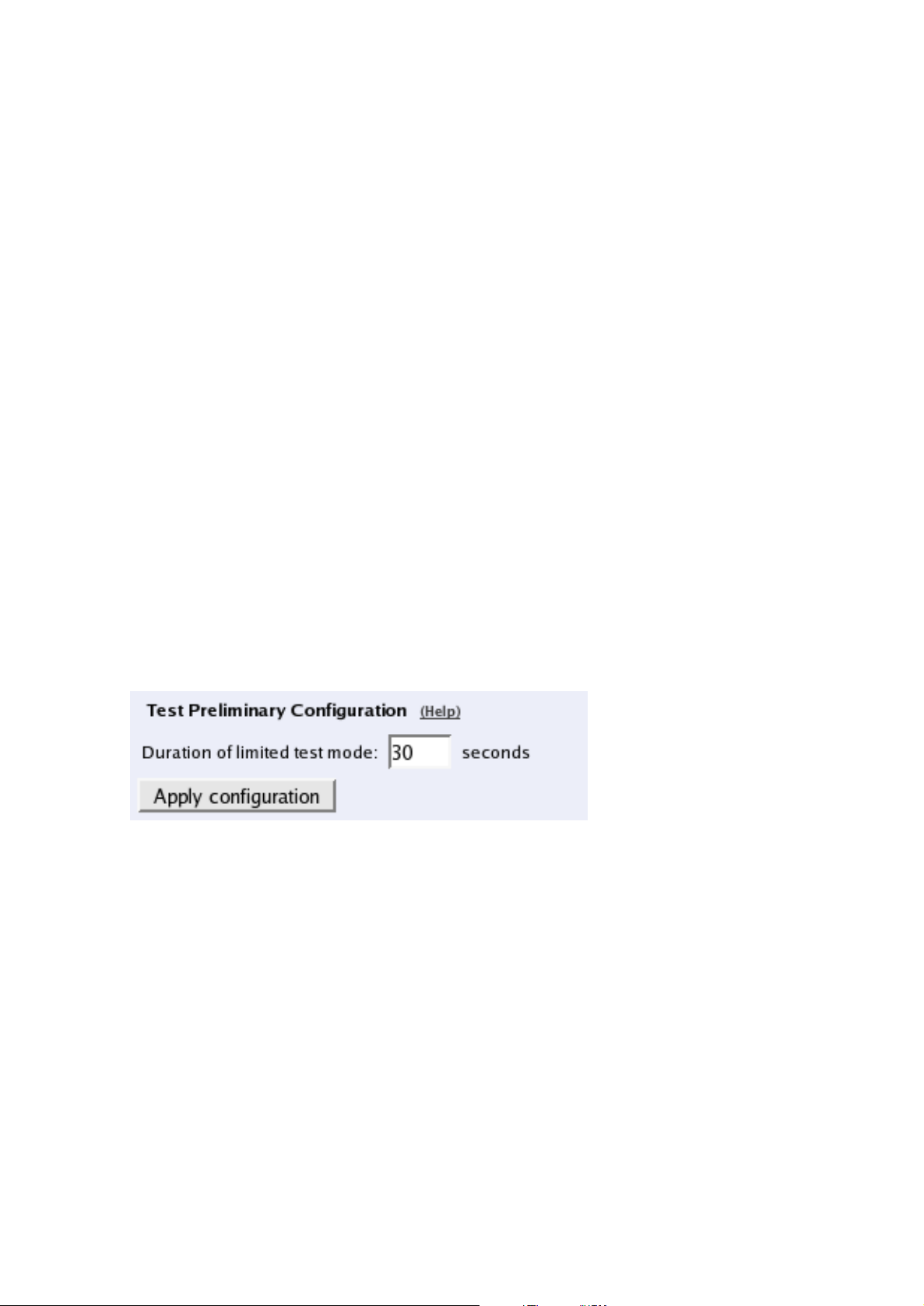
Chapter 6. Administration of the Telecommuting Module
Cancel
Reverts all the above fields to their previous configuration.
Look up all IP addresses again
Looks up the IP addresses for all DNS names on this page in the DNS servers you entered
on the Basic Configuration page.
This button will only be visible if a DNS server has been configured.
Save/Load Configuration
Here, you work with the preliminary and permanent configurations, save them and load new
configurations from previously saved configurations.
Test Preliminary Configuration
The settings you make in the web GUI will not be used automatically, but you must apply
them first. When there are settings which are not yet applied, a warning about this will be
shown on the web pages.
When Apply configuration is pressed, the Telecommuting Module will test the configuration before you make it permanent.
During test, the Telecommuting Module waits for you to press one of the three buttons
displayed. If you never see the three buttons, something in your preliminary configuration
(now tested) is wrong, which makes it impossible for you to access the configuration web
interface.
Duration of limited test mode
Here, you enter the time limit for the testing. If you do not press any button within this time,
the Telecommuting Module will assume that some part of your preliminary configuration
makes connecting impossible. When the timeout is reached, the Telecommuting Module
automatically reverts to the old permanent configuration. If this occurs, you will be informed
when trying to press a button.
Apply configuration
Saves the preliminary configuration to the permanent configuration and puts it into use. You
can test your preliminary configuration before finalizing it.
Three buttons are displayed during the test:
52
Page 61
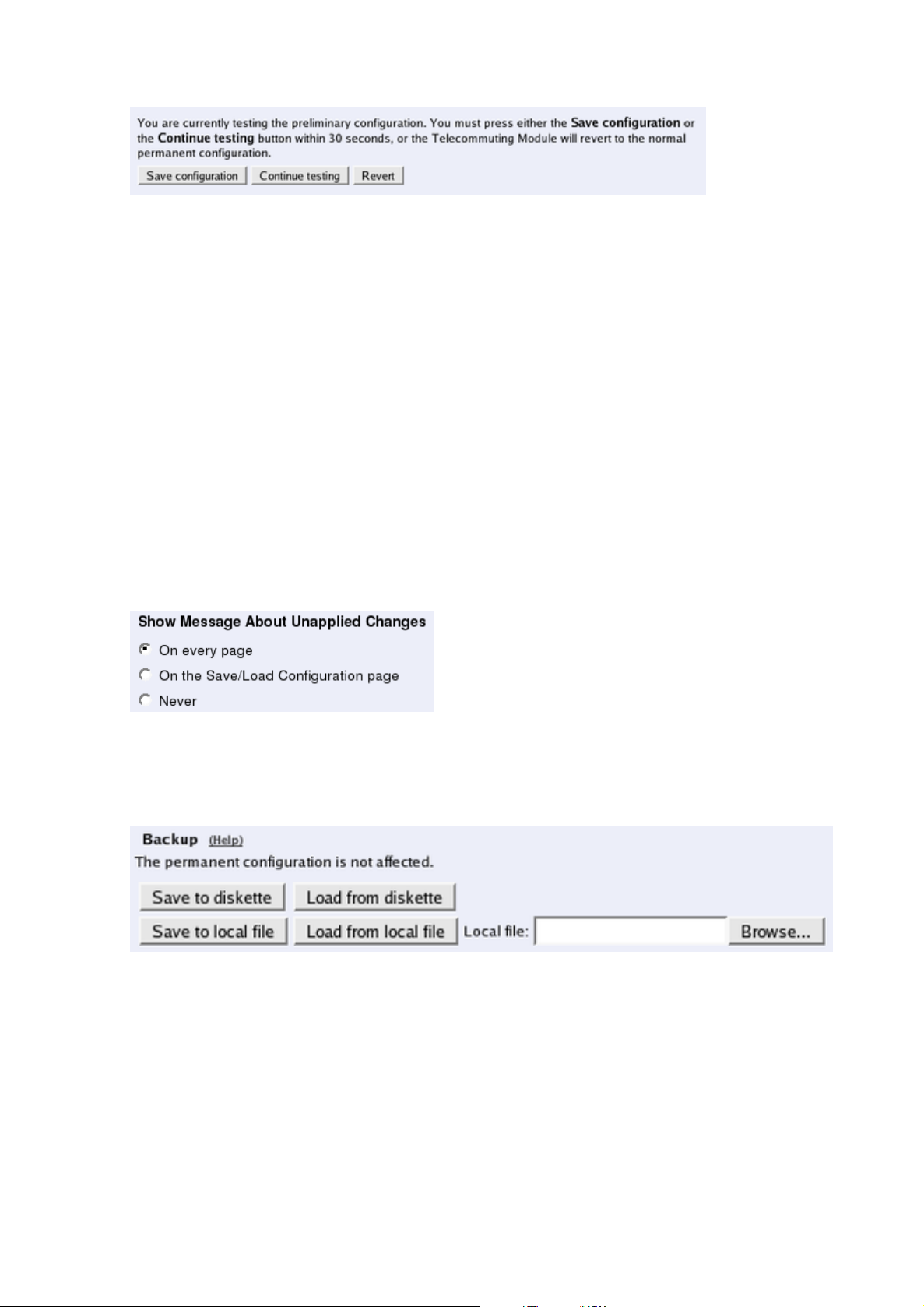
Chapter 6. Administration of the Telecommuting Module
Save configuration saves your preliminary configuration to the permanent configuration
and puts it into use.
Continue testing shows a new page with only the other two buttons.
Revert cancels this test of the preliminary configuration without saving.
If you do not press any button within the time limit, the Telecommuting Module will revert
to the old permanent configuration, just as if you had pressed Revert. This is useful if you
happen to configure your Telecommuting Module so it isn’t accessible from your browser.
After the timeout, pressing either of the three buttons will show a new page which will
inform you that the test run was aborted.
Restarting the Telecommuting Module by cycling the power also cancels the test.
Show Message About Unapplied Changes
When there are settings which are not yet applied, a warning about this will be shown on
the web pages. Select here where this message should be shown. The options are On every
page, On the Save/Load Configuration page (this page) and Never.
Backup
All configurations can be saved to and loaded from diskette or file. This does not affect the
permanent configuration.
Save to diskette
Insert a formatted diskette into the Telecommuting Module’s floppy drive and press Save to
diskette to save the preliminary configuration. Do not remove the diskette until the light on
the floppy drive goes out.
Check that you get a confirmation of the saving. If not, the diskette may be faulty.
53
Page 62
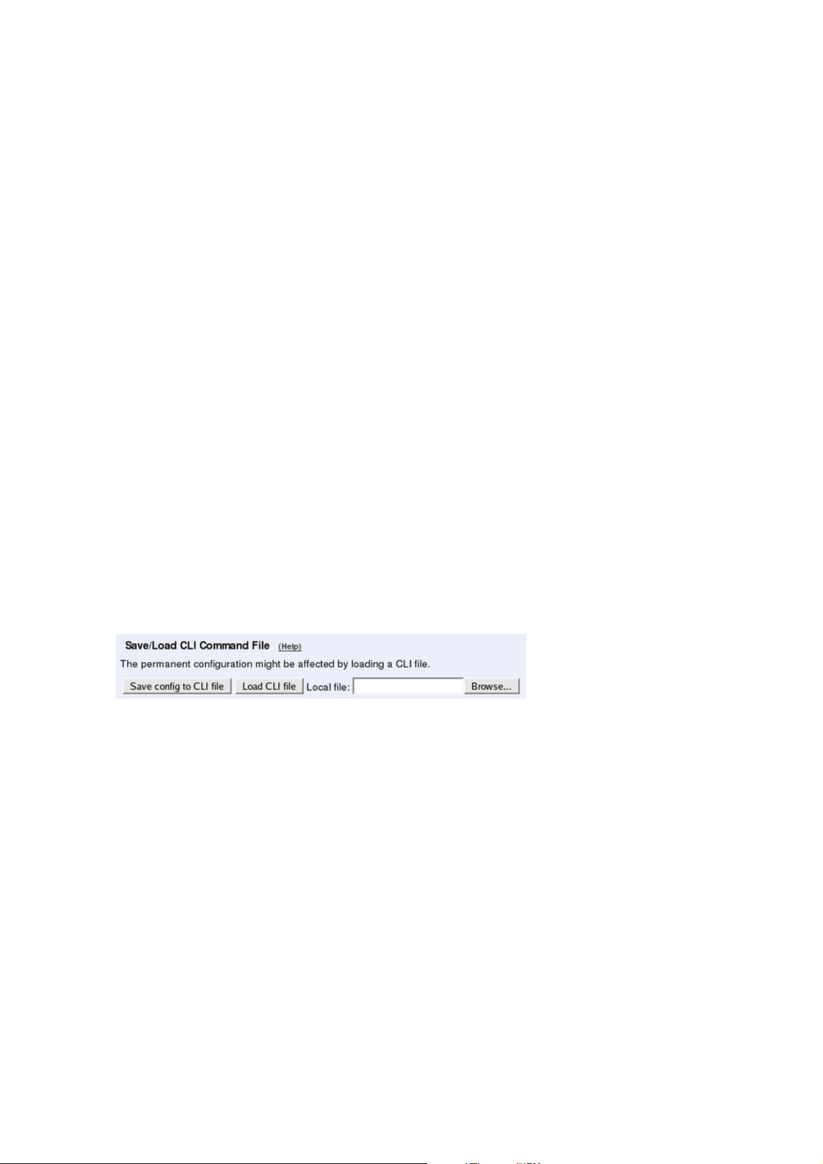
Chapter 6. Administration of the Telecommuting Module
Load from diskette
Insert the diskette with the saved configuration into the Telecommuting Module’s floppy
drive and press Load from diskette. Do not remove the diskette until the light on the floppy
drive goes out. The contents of the diskette are now loaded in the preliminary configuration.
Save to local file
Press Save to local file to save the preliminary configuration to the file you have selected. A
new window is opened where you enter the name of the file.
Load from local file
Press Load from local file to load a new preliminary configuration from the file you have
selected.
Browse
Browse is used to scan your local disk. The web browser opens a new window where you
can search among files and directories. Go to the right directory and select the file you want
to upload.
Save/Load CLI Command File
All configurations can be saved to and loaded from a CLI file (see chapter 18 of the Reference Guide for more information about the CLI). You can also edit the CLI file before it is
uploaded again.
Uploading a CLI file might affect the permanent configuration, as the CLI file can contain
commands that applies the configuration.
Save config to CLI file
Press Save config to CLI file to save the preliminary configuration to the file you have
selected. A new window is opened where you enter the name of the file.
Load CLI file
Press Load CLI file to upload a CLI file to the Telecommuting Module.
Browse
Browse is used to scan your local disk. The web browser opens a new window where you
can search among files and directories. Go to the right directory and select the file you want
to upload.
54
Page 63

Chapter 6. Administration of the Telecommuting Module
Revert to Old Configurations
You can revert to old configurations of the Telecommuting Module, either back to the last
configuration successfully applied, or to the configuration delivered with your Telecommuting Module from the factory.
Abort All Edits
Abort all edits copies the permanent configuration to the preliminary configuration. All
changes made in the preliminary configuration are deleted.
Reload Factory Configuration
The factory configuration is the standard configuration that is delivered with a Telecommuting Module. Click on this button to load this configuration into the preliminary configuration.
The permanent configuration is not affected.
55
Page 64

Chapter 6. Administration of the Telecommuting Module
56
Page 65

Chapter 7. Firewall and Client
Configuration
Additional configuration for the firewall and the SIP clients is required to make the Telecommuting Module work properly. The amount and nature of the configuration depends on
which Telecommuting Module Type was selected.
The DMZ type
Using the DMZ type, the network configuration should look like this:
The Firewall
The firewall to which the Telecommuting Module is connected should have the following
configuration:
SIP over UDP
• Let through UDP traffic between the Internet (all high ports) and the Telecommuting
Module (port 5060). You must allow traffic in both directions.
• Let through UDP traffic between the internal networks (all high ports) and the Telecom-
muting Module (port 5060). You must allow traffic in both directions.
• Let through UDP traffic between the Internet (all high ports) and the Telecommuting
Module (the port interval for media streams which was set on the Basic Settings page).
You must allow traffic in both directions.
• Let through UDP traffic between the internal networks (all high ports) and the Telecom-
muting Module (the port interval for media streams which was set on the Basic Settings
page). You must allow traffic in both directions.
• Let through UDP traffic between the Telecommuting Module (all high ports) and the In-
ternet (port 53). You must allow traffic in both directions. This enables the Telecommuting
Module to make DNS queries to DNS servers on the Internet. If the DNS server is located
on the same network as the Telecommuting Module, you don’t have to do this step.
• NAT between the Telecommuting Module and the Internet must not be used.
• NAT between the Telecommuting Module and the internal networks must not be used.
SIP over TCP/TLS
57
Page 66

Chapter 7. Firewall and Client Configuration
• Let through TCP traffic between the Internet (all high ports) and the Telecommuting Mod-
ule (ports 1024-32767). You must allow traffic in both directions.
• Let through TCP traffic between the internal networks (all high ports) and the Telecom-
muting Module (ports 1024-32767). You must allow traffic in both directions.
• Let through UDP traffic between the Internet (all high ports) and the Telecommuting
Module (the port interval for media streams which was set on the Basic Settings page).
You must allow traffic in both directions.
• Let through UDP traffic between the internal networks (all high ports) and the Telecom-
muting Module (the port interval for media streams which was set on the Basic Settings
page). You must allow traffic in both directions.
• Let through UDP traffic between the Telecommuting Module (all high ports) and the In-
ternet (port 53). You must allow traffic in both directions. This enables the Telecommuting
Module to make DNS queries to DNS servers on the Internet. If the DNS server is located
on the same network as the Telecommuting Module, you don’t have to do this step.
• NAT between the Telecommuting Module and the Internet must not be used.
• NAT between the Telecommuting Module and the internal networks must not be used.
The SIP clients
SIP clients will use the Telecommuting Module as their outgoing SIP proxy and as their
registrar (if they can’t be configured with the domain only). If you don’t want to use the
Telecommuting Module as the registrar, you should point the clients to the SIP registrar you
want to use.
Other
The DNS server used must have a record for the SIP domain, which states that the Telecommuting Module handles the domain, or many SIP clients won’t be able to use it (if you don’t
use plain IP addresses as domains).
The DMZ/LAN type
Using the DMZ/LAN type, the network configuration should look like this:
58
Page 67

Chapter 7. Firewall and Client Configuration
The Firewall
The firewall to which the Telecommuting Module is connected should have the following
configuration:
SIP over UDP
• Let through UDP traffic between the Internet (all high ports) and the Telecommuting
Module (port 5060). You must allow traffic in both directions.
• Let through UDP traffic between the Internet (all high ports) and the Telecommuting
Module (the port interval for media streams which was set on the Basic Settings page).
You must allow traffic in both directions.
• Let through UDP traffic between the Telecommuting Module (all high ports) and the In-
ternet (port 53). You must allow traffic in both directions. This enables the Telecommuting
Module to make DNS queries to DNS servers on the Internet. If the DNS server is located
on the same network as the Telecommuting Module, you don’t have to do this step.
• NAT between the Telecommuting Module and the Internet must not be used.
SIP over TCP/TLS
• Let through TCP traffic between the Internet (all high ports) and the Telecommuting Mod-
ule (ports 1024-32767). You must allow traffic in both directions.
• Let through UDP traffic between the Internet (all high ports) and the Telecommuting
Module (the port interval for media streams which was set on the Basic Settings page).
You must allow traffic in both directions.
• Let through UDP traffic between the Telecommuting Module (all high ports) and the In-
ternet (port 53). You must allow traffic in both directions. This enables the Telecommuting
Module to make DNS queries to DNS servers on the Internet. If the DNS server is located
on the same network as the Telecommuting Module, you don’t have to do this step.
• NAT between the Telecommuting Module and the Internet must not be used.
SIP clients
The SIP clients on the internal network should have the Telecommuting Module’s IP address
on that network as their outgoing SIP proxy and registrar.
Other
The DNS server used must have a record for the SIP domain, which states that the Telecommuting Module handles the domain, or many SIP clients won’t be able to use it (if you don’t
use plain IP addresses as domains).
The Standalone type
Using the Standalone type, the network configuration should look like this:
59
Page 68

Chapter 7. Firewall and Client Configuration
The SIP clients
SIP clients will use the Telecommuting Module as their outgoing SIP proxy and as their
registrar (if they can’t be configured with the domain only). If you don’t want to use the
Telecommuting Module as the registrar, you should point the clients to the SIP registrar you
want to use.
Other
The DNS server used must have a record for the SIP domain, which states that the Telecommuting Module handles the domain, or many SIP clients won’t be able to use it (if you don’t
use plain IP addresses as domains).
60
Page 69

Index
apply configuration, 52
authentication
of administrator, 48
backup, 53
Basic configuration
SIP, 35
CLI file
save to, 54
upload, 54
configuration
apply, 52
IP address, 48
permanent, 4
preliminary, 4
use protocol, 48
via HTTPS, 49
configuration computers, 49
configuration interface, 47
Content types, 42
default domain, 31
default gateway, 24
directly connected networks, 20
DMZ type, 17
configuration of DNS server, 58
configuration of firewall, 57
configuration of SIP clients, 58
DMZ/LAN type, 18
configuration of DNS server, 59
configuration of firewall, 58
configuration of SIP clients, 59
factory configuration, 54
gateway, 24
HTTPS
for configuration, 49
installing 3Com VCX IP Telecommuting
Module, 5
interface, 19
interface name, 20
IP policy, 31
limited test mode, 52
logging
of configuration, 50
SIP, 38
magic ping, 5
MIME types, 42
monitor SIP servers, 37
network interface, 19
network topology, 29
networks and computers, 26
permanent configuration, 4
physical device name, 19
ping policy, 31
port interval for media streams, 36
preliminary configuration, 4
router, 23
save configuration, 53
SIP, 35
content types, 42
signaling ports, 35
SIP basic configuration, 35
SIP domains
static, 39
SIP filtering, 41
SIP servers
monitored, 37
standalone type, 18
configuration of DNS server, 60
configuration of SIP clients, 60
standardnätsluss, 24
static routing, 23
subgroup
networks, 27
surroundings, 29
Telecommuting Module name, 31
Telecommuting Module Type
configuration, 19
DMZ, 17
DMZ/LAN, 18
standalone, 18
test mode, 52
turn off the 3Com VCX IP Telecommuting
Module, 13
VPN peer, 50
61
Page 70

 Loading...