

Page 1

3Com® Telecommuting Module
User Manual
Version 4.6.5
Page 2

Page 3

3Com® Telecommuting Module User Manual: Version 4.6.5
Part Number BETA
Published April 2009
3Com Corporation, 350 Campus Drive, Marlborough MA 01752-3064
Copyright © 2005, 3Com Corporation. All rights reserved. No part of this documentation may be reproduced in any
form or by any means or used to make any derivative work (such as translation, transformation, or adaptation)
without written permission from 3Com Corporation.
3Com Corporation reserves the right to revise this documentation and to make changes in content from time to time
without obligation on the part of 3Com Corporation to provide notification of such revision or change.
3Com Corporation provides this documentation without warranty, term, or condition of any kind, either implied or
expressed, including, but not limited to, the implied warranties, terms, or conditions of merchantability, satisfactory
quality, and fitness for a particular purpose. 3Com may make improvements or changes in the product(s) and/or the
program(s) described in this documentation at any time.
If there is any software on removable media described in this documentation, it is furnished under a license
agreement included with the product as a separate document, in the hardcopy documentation, or on the removable
media in a directory file named LICENSE.TXT or !LICENSE.TXT. If you are unable to locate a copy, please contact
3Com and a copy will be provided to you.
UNITED STATES GOVERNMENT LEGEND
If you are a United States government agency, then this documentation and the software described herein are
provided to you subject to the following:
All technical data and computer software are commercial in nature and developed solely at private expense. Software
is delivered as "Commercial Computer Software" as defined in DFARS 252.227-7014 (June 1995) or as a
"commercial item" as defined in FAR 2.101(a) and as such is provided with only such rights as are provided in
3Com’s standard commercial license for the Software. Technical data is provided with limited rights only as provided
in DFAR 252.227-7015 (Nov 1995) or FAR 52.227-14 (June 1987), whichever is applicable. You agree not to remove
or deface any portion of any legend provided on any licensed program or documentation contained in, or delivered to
you in conjunction with, this guide.
Unless otherwise indicated, 3Com registered trademarks are registered in the United States and may or may not be
registered in other countries.
3Com, the 3Com logo, NBX, and SuperStack are registered trademarks of 3Com Corporation. NBX NetSet, pcXset,
and VCX are trademarks of 3Com Corporation.
Adobe is a trademark and Adobe Acrobat is a registered trademark of Adobe Systems Incorporated. Microsoft,
Windows, Windows 2000, Windows NT, and Microsoft Word are registered trademarks of Microsoft Corporation.
All other company and product names may be trademarks of the respective companies with which they are associated.
Page 4

Page 5

Table of Contents
Part I. Introduction to 3Com VCX IP Telecommuting Module .......................................i
1. Introduction to 3Com VCX IP Telecommuting Module ...........................................1
2. Installing 3Com VCX IP Telecommuting Module ....................................................7
3. Configuring 3Com VCX IP Telecommuting Module..............................................17
Part II. How To...................................................................................................................27
4. How To Configure SIP .............................................................................................29
5. How To Configure Advanced SIP............................................................................55
Part III. Description of 3Com VCX IP Telecommuting Module Settings ....................73
6. Basic Configuration .................................................................................................75
7. Administration ....................................................................................................... 103
8. Network Configuration ..........................................................................................119
9. Logging.................................................................................................................. 137
10. SIP Services .........................................................................................................159
11. SIP Traffic ............................................................................................................185
12. Tools.....................................................................................................................217
13. Firewall and Client Configuration........................................................................223
Part IV. 3Com VCX IP Telecommuting Module Serial Console................................. 227
14. Basic Administration ...........................................................................................229
15. Command Line Reference ...................................................................................237
Part V. Appendices ..........................................................................................................319
A. More About SIP ....................................................................................................321
B. Troubleshooting.....................................................................................................329
C. Lists of Reserved Ports, ICMP Types and Codes, and Internet Protocols ............335
D. Definitions of terms...............................................................................................347
E. License Conditions ................................................................................................359
F. Obtaining Support for Your 3Com Products .........................................................431
Index.................................................................................................................................. 435
i
Page 6

ii
Page 7

Part I. Introduction to 3Com
VCX IP Telecommuting Module
Page 8

Page 9

Chapter 1. Introduction to 3Com VCX IP Telecommuting Module
Some of the functions of 3Com VCX IP Telecommuting Module are:
• SIP proxy: Forwarding of SIP requests.
• SIP registrar: Registration of SIP users.
• Protection against such attacks as address spoofing.
• Logging/alarm locally on the Telecommuting Module, via email and/or via syslog.
• Managing several logical/directly-connected networks and several network connec-
tions/physical networks.
• Administration of the Telecommuting Module through a web browser using http or https.
• QoS - bandwidth limitation and traffic prioritizing (using the QoS module).
• Failover - connect two Telecommuting Modules in parallel; one handles traffic and the
other acts as a hot standby.
• STUN server and Remote SIP Connectivity for SIP clients behind NAT boxes which are
not SIP aware (using the Remote SIP Connectivity module).
Note that some of the functions mentioned here are only available if the corresponding extension module has been installed.
What is a Telecommuting Module?
A Telecommuting Module is a device which processes traffic under the SIP protocol (see
RFC 3261). The Telecommuting Module receives SIP requests, processes them according to
the rules you have set up, and forwards them to the receiver.
The Telecommuting Module connects to an existing enterprise firewall through a DMZ port,
enabling the transmission of SIP-based communications without affecting firewall security.
SIP messages are then routed through the firewall to the private IP addresses of authorized
users on the internal network.
The Telecommuting Module can also be used as an extra gateway to the internal network
without connecting to the firewall, transmitting only SIP-based communications.
Configuration alternatives
The 3Com VCX IP Telecommuting Module can be connected to your network in three
different ways, depending on your needs.
Note that if the Standalone type is used, the interface which should receive traffic from the
outside must have a public IP address (no NAT).
1
Page 10
Chapter 1. Introduction to 3Com VCX IP Telecommuting Module
For a DMZ or DMZ/LAN type which uses a private IP address on the interface connected
to the DMZ of the firewall, its corresponding public IP address must be entered on the
Interoperability page.
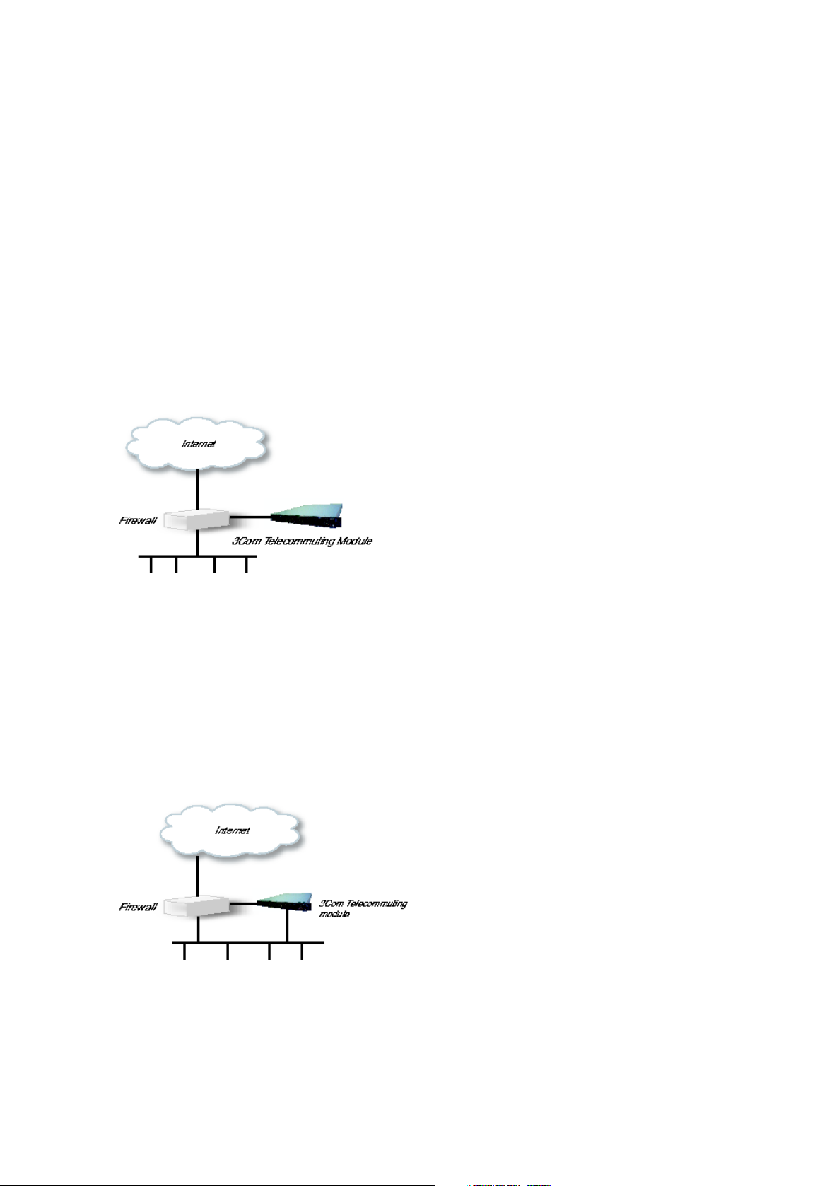
DMZ Configuration
Using this configuration, the Telecommuting Module is located on the DMZ of your firewall,
and connected to it with only one interface. The SIP traffic finds its way to the Telecommuting Module using DNS or by setting the Telecommuting Module as an outbound proxy on
the clients.
This is the most secure configuration, since all traffic goes through both your firewall and
your Telecommuting Module. It is also the most flexible, since all networks connected to
any of your firewall’s interfaces can be SIP-enabled.
The drawback is that the SIP traffic will pass the firewall twice, which can decrease performance.
Fig 1. Telecommuting Module in DMZ configuration.
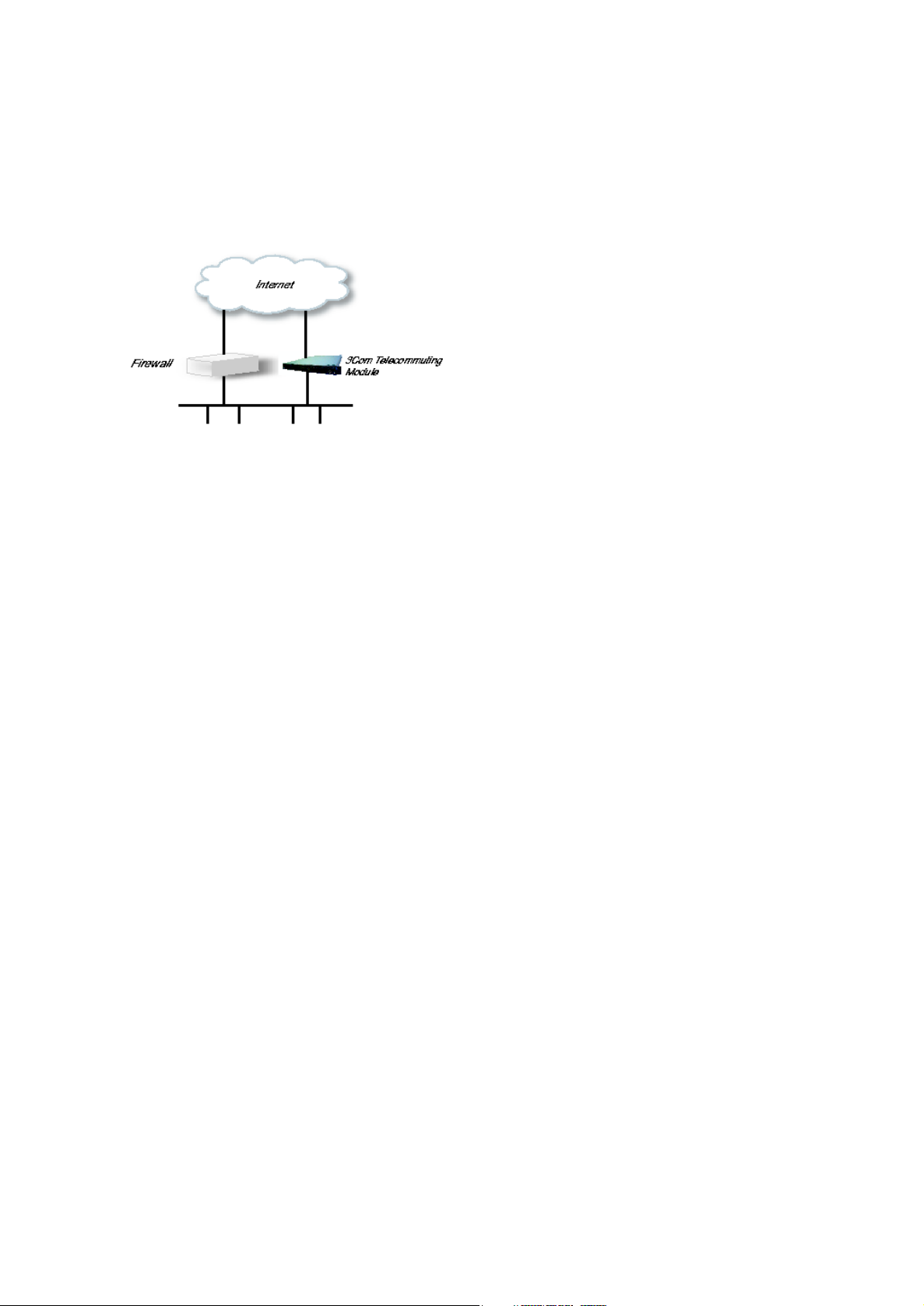
DMZ/LAN Configuration
Using this configuration, the Telecommuting Module is located on the DMZ of your firewall,
and connected to it with one of the interfaces. The other interfaces are connected to your
internal networks. The Telecommuting Module can handle several networks on the internal
interface even if they are hidden behind routers.
This configuration is used to enhance the data throughput, since the traffic only needs to pass
your firewall once.
Fig 2. Telecommuting Module in DMZ/LAN configuration.
2
Page 11
Chapter 1. Introduction to 3Com VCX IP Telecommuting Module
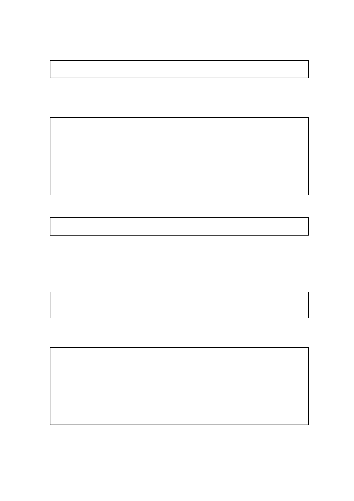
Standalone Configuration
Using this configuration, the Telecommuting Module is connected to the outside on one
interface and your internal networks on the others.
Use this configuration only if your firewall lacks a DMZ interface, or for some other reason
cannot be configured for the DMZ or DMZ/LAN alternatives.
Fig 3. Telecommuting Module in Standalone configuration.
Quick guide to 3Com VCX IP Telecommuting Module installation
3Com VCX IP Telecommuting Module is easy to install:
• Select an IP address for the Telecommuting Module on your network.
• The network interfaces are marked with 1 and 2. These numbers correspond to the physi-
cal interfaces eth0 and eth1 respectively, the latter which should be use in the installation
program.
• Plug in the power cord and turn on the Telecommuting Module.
• Wait while the Telecommuting Module boots up.
• Connect the network cables to the network interfaces.
• Connect a monitor and a keyboard to the Telecommuting Module.
• Log in as admin. No password is needed the first time you log in.
• Run the installation script, where you assign IP address, configuration computers and
password.
• Direct your web browser to the IP address of the Telecommuting Module.
• Now you can see the main page of 3Com VCX IP Telecommuting Module. Click on the
Telecommuting Module Type link and select the configuration for your Telecommuting
Module. The types are described on the corresponding help page.
• Go to the Basic Configuration page and enter a DNS server. See also the Basic Config-
uration section.
• Go to the Access Control page and make settings for the configuration of the Telecom-
muting Module. See also the Access Control section.
3
Page 12

Chapter 1. Introduction to 3Com VCX IP Telecommuting Module
• Go to the Network Interface 1 page under Network Configuration and enter the neces-
sary configuration. See also the Interface section. Note that the Telecommuting Module
must have at least one IP address which can be reached from the Internet.
• If one of the Telecommuting Module Types DMZ/LAN or Standalone was chosen, move
on to the Network Interface 2 page and give the Telecommuting Module at least one IP
address on this interface and state the networks connected to the interface. See also the
Interface section.
• Go to the Default Gateway page and enter a Default gateway. See also the Default
Gateway section.
• Go to the Networks and Computers page. Define the networks that will send and receive
SIP traffic using the Telecommuting Module. Usually, you need at least one network per
interface of the firewall connected to the Telecommuting Module (or, for the Standalone
type, per interface of the Telecommuting Module). Some computers should be handled
separately, and they therefore need their own networks. See also the Networks and Computers section.
• Go to the Surroundings page (for the DMZ Telecommuting Module Type) and state the
networks connected to the firewall. See also the Surroundings section in the chapter titled
Network Configuration.
• Go to Basic Settings under SIP Services and switch the SIP module on. Enter the port
range to be used by the Telecommuting Module for the media streams. See also the Basic
Settings section.
• Go to the Filtering page under SIP Traffic to create Proxy rules for the SIP traffic from
different networks and allow the content types which should be allowed in the SIP media
streams. See also the Filtering section.
• Go to the Interoperability page. Set URI Encoding to "Keep username in URIs".
• Go to the Save/Load Configuration page under Administration. Select Apply configu-
ration. Now you can test your new configuration and save it permanently if you are satisfied with it. If the configuration is not satisfactory, select Revert or restart the Telecommuting Module. The old configuration will remain.
• When the configuration has been applied, you should save a backup to file. Press Save to
local file to save the configuration.
When the Telecommuting Module is configured, the firewall connected to it must also be
reconfigured (for the DMZ and DMZ/LAN Telecommuting Module Types).
• Allow UDP and TCP traffic in the port interval used for media streams by the Telecom-
muting Module, and port 5060. This traffic must be allowed to all networks which should
be reached by SIP traffic.
See also the chapter titled Firewall and Client Configuration, for information on configuring
the firewall and the SIP clients.
4
Page 13

Chapter 1. Introduction to 3Com VCX IP Telecommuting Module
About settings in 3Com VCX IP Telecommuting Module
3Com VCX IP Telecommuting Module uses two sets of Telecommuting Module configurations: preliminary and permanent configuration. The permanent configuration is what
is used in the active Telecommuting Module. The preliminary configuration is where you
change and set the configuration. See chapter 3, Configuring 3Com VCX IP Telecommuting
Module, for instructions.
The changes you make in the preliminary configuration are not stored in the permanent
configuration until you click on Apply configuration on the Save/Load Configuration
page under Administration.
The password configuration and time setting are the exceptions to this rule; they are saved
immediately. Change the administrator passwords and create more administrator users on
the User Administration page under Administration.
3Com VCX IP Telecommuting Module displays serious errors in red, e.g., if mandatory
information is not entered. Blank fields are shown in red. Fields that you correct remain red
until you select Save, Add new rows or update the page in some other way.
If you have a web connection with the Telecommuting Module that is inactive for 10 minutes, it will ask for a password again.
Always log out from the Telecommuting Module administration interface when you are not
using it. Press the Log out button on the left to log out.
The terms used in the book are explained in appendix D, Definitions of Terms.
For a general description of how to configure and administer the Telecommuting Module,
see chapter 3, Configuring 3Com VCX IP Telecommuting Module.
5
Page 14

Chapter 1. Introduction to 3Com VCX IP Telecommuting Module
6
Page 15

Chapter 2. Installing 3Com VCX IP Telecommuting Module
Installation
There are three ways to install an 3Com VCX IP Telecommuting Module: using a serial
cable, using a diskette or perform a magic ping.
Installation with a serial cable or a diskette requires being at the same place as the Telecommuting Module, but will give more options for the start configuration.
Installation with magic ping does not require being on the same place as the Telecommuting
Module (but the computer has to be connected to the same logical network as the Telecommuting Module), but restricts the start configuration.
Installation with magic ping
You can use the magic ping to set an IP address for the Telecommuting Module. This is how
to perform a magic ping:
• Plug in the power cord and turn the Telecommuting Module on.
• Wait while the Telecommuting Module boots up.
• Connect the network cables to the network interfaces.
• Find out the MAC address of the Telecommuting Module (printed on the Telecommuting
Module label). This is the MAC address of Network Interface 1.
• Add a static entry in your local ARP table consisting of the Telecommuting Module’s
MAC address and the IP address it should have on eth0.
This is how to add a static ARP entry if you use a Windows computer:
Run the command command (or cmd).
In the Command window, enter the command arp -s ipaddress macaddress where ipad-
dress is the new IP address for the eth0 interface, and macaddress is the MAC address
printed on the Telecommuting Module, but with all colons (:) replaced with dashes (-).
• Ping this IP address to give the Telecommuting Module its new IP address. You should
receive a ping reply if the address distribution was successful.
• Configure the rest through a web browser.
The magic ping will not set any password. Set a password immediately via the web user
interface. Before any configuration has been made, only the computer which performed the
magic ping will be able to configure the 3Com VCX IP Telecommuting Module.
Installation with a serial cable
These steps are performed when installing with a serial cable:
7
Page 16

Chapter 2. Installing 3Com VCX IP Telecommuting Module
• Connect the Telecommuting Module to your workstation with the enclosed serial cable.
• Plug in the power cord and turn the Telecommuting Module on.
• Wait while the Telecommuting Module boots up.
• Log on from your workstation.
• Run the installation program (see following instructions).
• Connect the network cables to the network interfaces.
• Configure the rest through a web browser.
Connect the Telecommuting Module to your workstation with the enclosed serial cable,
plug in the power cord and turn the Telecommuting Module on. You will have to wait a few
minutes while it boots up.
• If you use a Windows workstation, connect like this: Start Hyperterm. A Location dia-
logue will show, asking for your telephone number and area. Click Cancel followed by
Yes. Then you will be asked to make a new connection. Type a name for this connection, select an icon and click OK. The Location dialogue will show again, so click Cancel
followed by Yes.
Now you can select Connect using COM1 and click OK. A Port settings dialogue will
show, where you select 19200 as Bits per second. Use the default configuration for all
other settings. Click OK and wait for a login prompt. (In some cases you have to press
Return to get the login prompt.)
• If you use a Linux workstation, connect like this: Make sure that there is a symbolic
link named /dev/modem which points to the serial port you connected the Telecommuting
Module to. Connect using minicom with the bit rate 19200 bits/s, and wait for a login
prompt.
Log on as the user admin. The first time you log on, no password is required. You set the
password when you run the installation script, which starts automatically when you have
logged on.
Each network interface is marked with a name (1 and 2), which corresponds to a tab under
Network Configuration. All eth interfaces belong to ethernet cards and should only be
connected using ethernet cables.
Decide which computer(s) are allowed to configure 3Com VCX IP Telecommuting Module
and enter the name of the network interface to which they are connected, for example, eth0.
You must use the physical device name (eth0 and eth1).
Enter the IP address of the Telecommuting Module on this interface and the network mask
for the network.
A network mask can be written in two ways in 3Com VCX IP Telecommuting Module:
• The first looks just like an IP address, for example 255.255.192.0 or 255.255.254.0.
8
Page 17

Chapter 2. Installing 3Com VCX IP Telecommuting Module
• The other way is as a number between 0 and 32. An IP address has 32 bits, where the
number of the network mask indicates how many bits are used in the network’s addresses.
The rest of the bits identifies the computer on the network.
Now, you can select to deactivate any network interfaces. Select y to deactivate all interfaces
but the one you just configured. The remaining network interfaces can be activated later
when you complete the configuration via the web interface from your work station. This
only applies to interfaces which was previously active; you can’t activate interfaces with this
setting.
Now enter the computer or computers from which the Telecommuting Module may be configured (the configuration computers).
Then enter a password for the Telecommuting Module. This is the password you use in your
web browser to access and change the Telecommuting Module’s configuration. Finally, you
can reset all other configuration if you want to.
Following is a sample run of the installation program.
3Com VCX IP Telecommuting Module Administration
1. Basic configuration
2. Save/Load configuration
5. Wipe email logs
6. Set password
7. Command line interface
a. About
q. Exit admin
==>
Select 1 to install your 3Com VCX IP Telecommuting Module.
Basic unit installation program version 4.6.5
Press return to keep the default value
Network configuration inside:
Physical device name[eth0]:
IP address [0.0.0.0]: 10.47.2.242
Netmask/bits [255.255.255.0]: 255.255.0.0
Deactivate other interfaces? (y/n) [n]
Computers from which configuration is allowed:
You can select either a single computer or a network.
Configure from a single computer? (y/n) [y]
9
Page 18
Chapter 2. Installing 3Com VCX IP Telecommuting Module
If you choose to allow only one computer to configure the Telecommuting Module, you are
asked for the IP address (the mask is set automatically).
IP address [0.0.0.0]: 10.47.2.240
If this IP address is not on the same network as the IP address of the Telecommuting Module, you are asked for the router. Enter the IP address of the router on the network where
the Telecommuting Module is connected. Then enter the network address and mask of the
network containing the configuring computer.
Static routing:
The computer allowed to configure from is not on a network local to
this unit. You must configure a static route to it. Give
the IP address of the router on the network the unit is on.
The IP address of the router [0.0.0.0]: 10.47.3.1
Network address [10.47.0.0]: 10.10.0.0
Netmask [255.255.255.0]:
You can choose to allow several computers to configure the Telecommuting Module, by
answering no to the question:
Configure from a single computer? (y/n) [y] n
The installation program then asks for the network number. The configuration computers
must be entered as a complete subnet, i. e. a range which can be written as a network number
and a netmask (like 10.47.2.128 with netmask 255.255.255.128, which means the computers
10.47.2.128-10.47.2.255). All computers on this subnet will be allowed to configure the
Telecommuting Module. For more information about network numbers and netmasks, see
chapter 3, Configuring 3Com VCX IP Telecommuting Module.
Network number [0.0.0.0]: 10.47.2.0
Netmask/bits [255.255.255.0]: 255.255.255.0
If the network or partial network is not directly connected to the Telecommuting Module,
you must enter the IP address of the router leading to that network. Then enter the network’s
address and mask.
Static routing:
The network allowed to configure from is not on a network local to this
unit. You must configure a static route to it. Give the
IP address of the router on the network this unit is on.
The IP address of the router [0.0.0.0]: 10.47.3.1
Network address [10.47.0.0]: 10.10.0.0
Netmask [255.255.255.0]:
Then enter a password.
10
Page 19

Chapter 2. Installing 3Com VCX IP Telecommuting Module
Password []:
Finally, you are asked if you want to reset other configuration.
Other configuration
Do you want to reset the rest of the configuration? (y/n) [n]
If you answer n, nothing is removed. If you answer y, you have three alternatives to select
from:
1. Clear as little as possible. This is the alternative that is used if you answer n to the
question above. Both the preliminary and the permanent configurations will be updated
with the configuration specified above.
2. Revert to the factory configuration and then apply the configuration specified above.
This will affect the permanent but not the preliminary configuration.
3. Revert to the factory configuration and empty all logs and then apply the configuration
specified above. Both the preliminary and the permanent configurations will be affected.
Select the update mode, which is what you want to remove.
Update mode (1-3) [1]:
All configuration is now complete. The installation program shows the configuration and
asks if it is correct.
yes saves the configuration.
no runs the installation program over again.
abort ends the installation program without saving.
You have now entered the following configuration
Network configuration inside:
Physical device name: eth0
IP address: 192.168.150.2
Netmask: 255.255.255.0
Deactivate other interfaces: no
Computer allowed to configure from:
IP address: 192.168.128.3
Password: eeyore
The rest of the configuration is kept.
Is this configuration correct (yes/no/abort)? yes
11
Page 20

Chapter 2. Installing 3Com VCX IP Telecommuting Module
Now, finish configuration of the Telecommuting Module from the computer/computers specified in the installation program.
Installation with a diskette
These steps are performed when installing with a diskette:
• Select an IP address and store it on the installation diskette as described below.
• Insert the installation diskette into the Telecommuting Module’s floppy drive.
• Plug in the power cord and turn the Telecommuting Module on.
• Connect the network cables to the network interfaces.
• Wait while the Telecommuting Module boots up.
• Configure the rest through a web browser.
You must first insert the diskette into your PC. If the PC is running Windows, open a Command window and run the finst-en script from the diskette. If the PC is running Linux, mount
the diskette, change directory to the mounted one, and run the finst-en script.
Each network interface is marked with a name (1 and 2), which corresponds to a tab under
Network Configuration. All eth interfaces belong to ethernet cards and should only be
connected using ethernet cables.
Decide which computer(s) are allowed to configure 3Com VCX IP Telecommuting Module
and enter the name of the network interface to which they are connected, for example, eth0.
You must use the physical device name (eth0 and eth1).
Enter the IP address of the Telecommuting Module on this interface and the network mask
for the network.
A network mask can be written in two ways in 3Com VCX IP Telecommuting Module:
• The first looks just like an IP address, for example 255.255.192.0 or 255.255.254.0.
• The other way is as a number between 0 and 32. An IP address has 32 bits, where the
number of the network mask indicates how many bits are used in the network’s addresses.
The rest of the bits identifies the computer on the network.
Now, you can select to deactivate any network interfaces. Select y to deactivate all interfaces
but the one you just configured. The remaining network interfaces can be activated later
when you complete the configuration via the web interface from your work station. This
only applies to interfaces which was previously active; you can’t activate interfaces with this
setting.
Now enter the computer or computers from which the Telecommuting Module may be configured (the configuration computers).
Then enter a password for the Telecommuting Module. This is the password you use in your
web browser to access and change the Telecommuting Module’s configuration. Finally, you
can reset all other configuration if you want to.
Following is a sample run of the installation program on the diskette.
12
Page 21

Chapter 2. Installing 3Com VCX IP Telecommuting Module
Basic unit installation program version 4.6.5
Press return to keep the default value
Network configuration inside:
Physical device name[eth0]:
IP address [0.0.0.0]: 10.47.2.242
Netmask/bits [255.255.255.0]: 255.255.0.0
Deactivate other interfaces? (y/n) [n]
Computers from which configuration is allowed:
You can select either a single computer or a network.
Configure from a single computer? (y/n) [y]
If you choose to allow only one computer to configure the Telecommuting Module, you are
asked for the IP address (the netmask is set automatically).
IP address [0.0.0.0]: 10.47.2.240
If this IP address is not on the same network as the inside of the Telecommuting Module,
you are asked for the router. Enter the IP address of the router on the network where the
Telecommuting Module is connected. Now enter the network address and mask of the network containing the configuring computer.
Static routing:
The computer allowed to configure from is not on a network local to
this unit. You must configure a static route to it. Give
the IP address of the router on the network the unit is on.
The IP address of the router [0.0.0.0]: 10.47.3.1
Network address [10.47.0.0]: 10.10.0.0
Netmask [255.255.255.0]:
You can choose to allow several computers to configure the Telecommuting Module, by
answering no to the question:
Configure from a single computer? (y/n) [y] n
The installation program then asks for the network number. The network number is the lowest IP address in the series of numbers that includes the configuration computers (see chapter
3, Configuring 3Com VCX IP Telecommuting Module). The network mask determines the
number of computers that can act as configuration computers.
Network number [0.0.0.0]: 10.47.2.0
Netmask/bits [255.255.255.0]: 255.255.255.0
13
Page 22
Chapter 2. Installing 3Com VCX IP Telecommuting Module
If the network or partial network is not directly connected to the Telecommuting Module,
you must enter the IP address of the router leading to that network. Then enter the network’s
address and mask.
Static routing:
The network allowed to configure from is not on a network local to this
unit. You must configure a static route to it. Give the
IP address of the router on the network this unit is on.
The IP address of the router [0.0.0.0]: 10.47.3.1
Network address [10.47.0.0]: 10.10.0.0
Netmask [255.255.255.0]:
Then enter a password.
Password []:
Finally, you are asked if you want to reset other configuration.
Other configuration
Do you want to reset the rest of the configuration? (y/n) [n]
If you answer n, nothing is removed. If you answer y, you have three alternatives to select
from:
1. Clear as little as possible. This is the alternative that is used if you answer n to the
question above. Both the preliminary and the permanent configurations will be updated
with the configuration specified above.
2. Revert to the factory configuration and then apply the configuration specified above.
This will affect the permanent but not the preliminary configuration.
3. Revert to the factory configuration and empty all logs and then apply the configuration
specified above. Both the preliminary and the permanent configurations will be affected.
Select the update mode, which is what you want to remove.
Update mode (1-3) [1]:
All configuration is now complete. The installation program shows the configuration and
asks if it is correct.
yes saves the configuration.
no runs the installation program over again.
abort ends the installation program without saving.
Now, eject the diskette from your PC and insert it into the Telecommuting Module’s floppy
drive. Then power up the Telecommuting Module and wait for it to boot. Then, finish configuration of the Telecommuting Module from the computer/computers specified in the installation program.
14
Page 23

Chapter 2. Installing 3Com VCX IP Telecommuting Module
Note that the diskette contains a command to erase certain parts of the configuration
during boot when the diskette is inserted. Make sure to eject it once the Telecommuting
Module has booted up to avoid future loss of data.
If you happen to forget the administrator password for the Telecommuting Module, you
can insert the diskette into the Telecommuting Module again and boot it. Note that if you
selected anything but 1 as the update mode, you will lose configuration when doing this.
Turning off a Telecommuting Module
Backup the Telecommuting Module configuration (just in case something should happen).
You do this on the Save/Load Configuration page under Administration. Once this is
done, just turn the computer off. The computer that runs 3Com VCX IP Telecommuting
Module is specially designed so that you can switch it off without causing any problems in
the file structure.
Remember to lock up the Telecommuting Module
The Telecommuting Module is a computer with special software, and must be protected from
unauthorized physical access just as other computers performing critical tasks. A locked up
Telecommuting Module protects against:
• connecting to the console
• connecting a keyboard and monitor
• changing the administrator password using the installation diskette.
• changing BIOS configuration to allow the Telecommuting Module to be booted from a
diskette
For more information about the necessary configuration, see chapter 3, Configuring 3Com
VCX IP Telecommuting Module.
15
Page 24

Chapter 2. Installing 3Com VCX IP Telecommuting Module
16
Page 25
Chapter 3. Configuring 3Com VCX IP
Telecommuting Module
You connect to your 3Com VCX IP Telecommuting Module by entering its name or IP
address in the Location box of your web browser.
Logging on
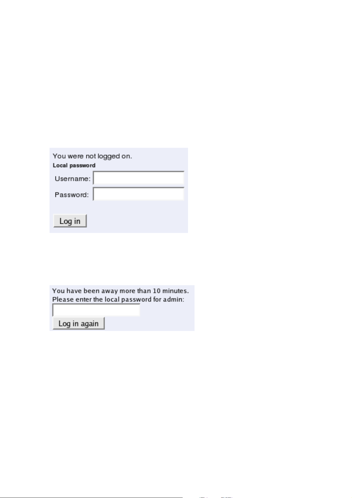
Before you can configure the Telecommuting Module, you must enter your administrator
username and password or RADIUS username and password. The admin user is predefined
with complete administration privileges.
Log on again
If you have a web connection for Telecommuting Module configuration that is inactive for
more than 10 minutes, you must enter the password again and click on one of the buttons
Keep changes below and Abandon changes below.
On all pages where changes have been made, the two buttons Keep changes below and
Abandon changes below will be shown when you log on again. Keep changes below connects you to the Telecommuting Module and stores the preliminary configuration you have
changed. Abandon changes below connects you to the Telecommuting Module and discards the changes you have made on this page.
On pages where nothing has been changed, the Log in again button is displayed. Enter the
password and click on the button to re-connect to the Telecommuting Module.
The Telecommuting Module’s encryption key is changed every 24 hours. If you have a web
connection for Telecommuting Module configuration when this happens, you must enter the
password again. This works in the same way as when your connection has been inactive for
more than 10 minutes (see above).
17
Page 26
Chapter 3. Configuring 3Com VCX IP Telecommuting Module
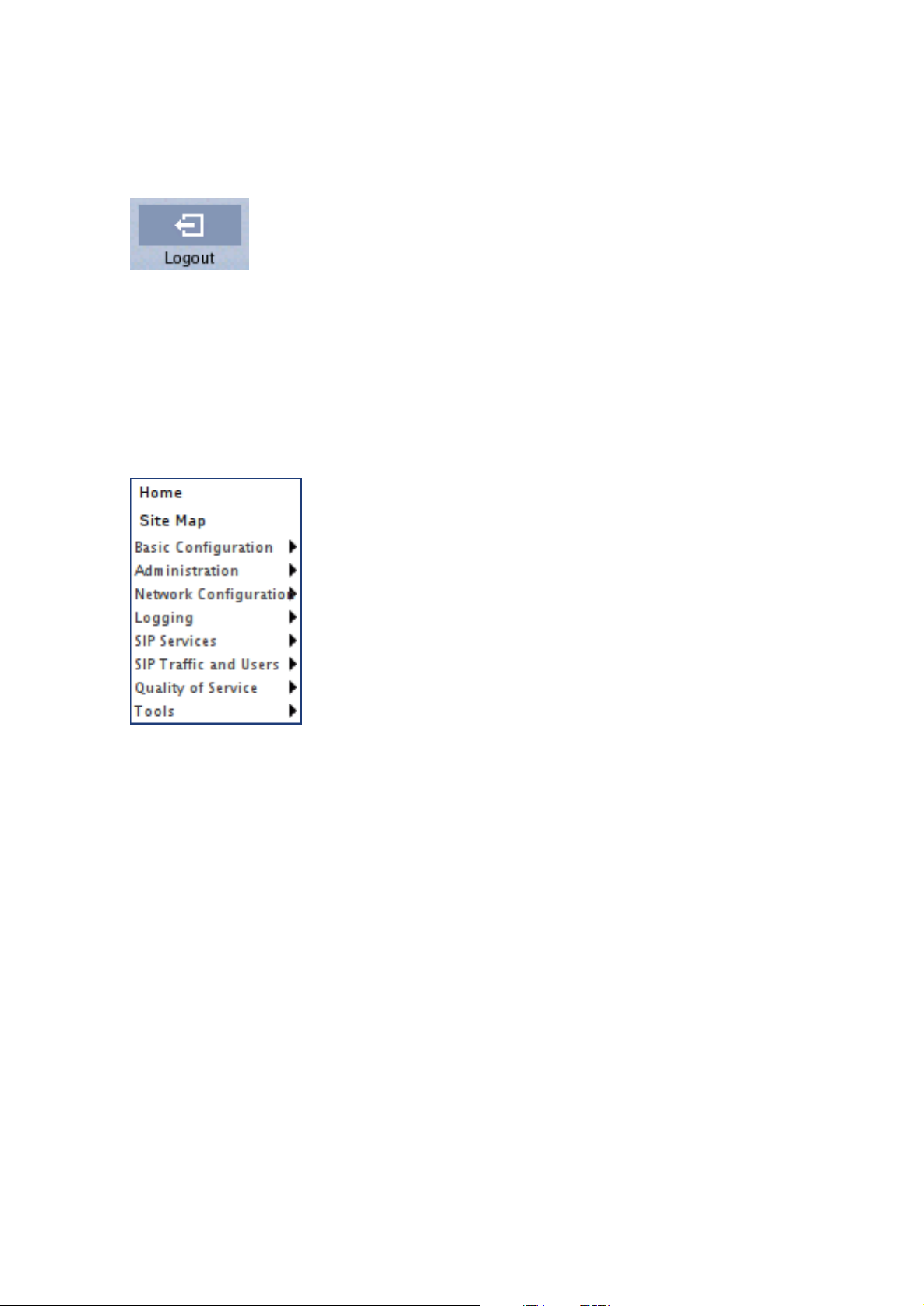
Log out
When you have finished looking at or adding settings, you should log out from the Telecommuting Module. Below the menu there is a Log out button which will end your session.
Note: You will not be logged out automatically just by directing your web browser to a
different web address. You should log out using the button to make the browser forget your
username and password.
Navigation
There is a menu for quick navigation to all configuration pages. On top of the page, you also
see the name of the Telecommuting Module.
Site Map
The Site Map is the first page displayed when you have logged on the Telecommuting
Module. From this page, you can access Basic Configuration, Administration, Network
Configuration, Logging, SIP Services, SIP Traffic, Failover, Virtual Private Networks,
Quality of Service, and Tools. You can also access a special page by the text links below
each category name.
18
Page 27

Chapter 3. Configuring 3Com VCX IP Telecommuting Module
Basic Configuration
Under Basic Configuration, select Telecommuting Module Type and the name of the
Telecommuting Module. You also enter IP addresses for DNS servers. Here you also configure if the Telecommuting Module should interact with a RADIUS, a DynDNS or an SNMP
server.
Administration
Under Administration, you store or load a configuration. You can also test your configuration to see if it works the way you planned, upgrade or reboot your Telecommuting Module,
set date and time, and configure administration users and passwords.
Network Configuration
Under Network Configuration, you enter the Telecommuting Module’s IP address, the
routing for the different networks, and define groups of IP addresses which are used in
various settings of the Telecommuting Module.
Logging
Under Logging, you specify the type of traffic you want to log/alarm and how it should be
logged. You can also view the logs and the traffic load here.
SIP Services
Under SIP Services, you configure SIP encryption, interoperability settings, Remote SIP
Connectivity and VoIP Survival.
SIP Traffic
Under SIP Traffic, you configure the SIP traffic and the SIP registrar in the Telecommuting
Module. You can also view current user registrations and SIP sessions.
19
Page 28

Chapter 3. Configuring 3Com VCX IP Telecommuting Module
Failover
Under Failover, you configure the failover team and its dedicated network. You can also
view the status of the other team member.
Virtual Private Networks
Under Virtual Private Networks, you configure the encrypted traffic between your
Telecommuting Module and other VPN gateways and clients. VPN connections can be made
using IPSec or PPTP.
Quality of Service
The Quality of Service module enables bandwidth limitation and prioritizing for different
kinds of traffic through the Telecommuting Module. For each interface you can state a guaranteed and a maximum bandwidth for classes of traffic.
You can also set bandwidth limits for SIP calls and ensure that when there is not enough
bandwidth for call media, the call will not be set up at all.
Tools
Under Tools, you find tools for troubleshooting the Telecommuting Module and the network.
Overview of configuration
Start by installing the Telecommuting Module as described in chapter 2, Installing 3Com
VCX IP Telecommuting Module.
Select the Telecommuting Module Type.
The Telecommuting Module must have at least one IP address for each network card to
work. A routing, or path, for each network must also be set on the interface pages under
Network Configuration. Go to the Networks and Computers page and enter the networks
which are using the Telecommuting Module. For a DMZ Telecommuting Module, also state
the Telecommuting Module’s Surroundings.
Go to SIP Services and switch the SIP module on.
Then move on to SIP Traffic and configure the Telecommuting Module to state how SIP
requests should be processed.
Use logging to analyze the traffic that passes through the Telecommuting Module. Choose
to log locally on the Telecommuting Module, send logs to a syslog server or send them by
email to an email address. Specify the type of logging wanted under Logging. This is also
where the logs of traffic through the Telecommuting Module are viewed.
When the configuration is complete, apply it. Go to Save/Load Configuration under Ad-
ministration. Select Apply configuration. Now the new configuration is tested. Save it
permanently if it works satisfactorily. If the configuration is not satisfactory, select Revert
or restart the Telecommuting Module. The old configuration will remain.
20
Page 29
Chapter 3. Configuring 3Com VCX IP Telecommuting Module
When the configuration has been applied, you should save a backup to file. Press Save to
local file to save the configuration.
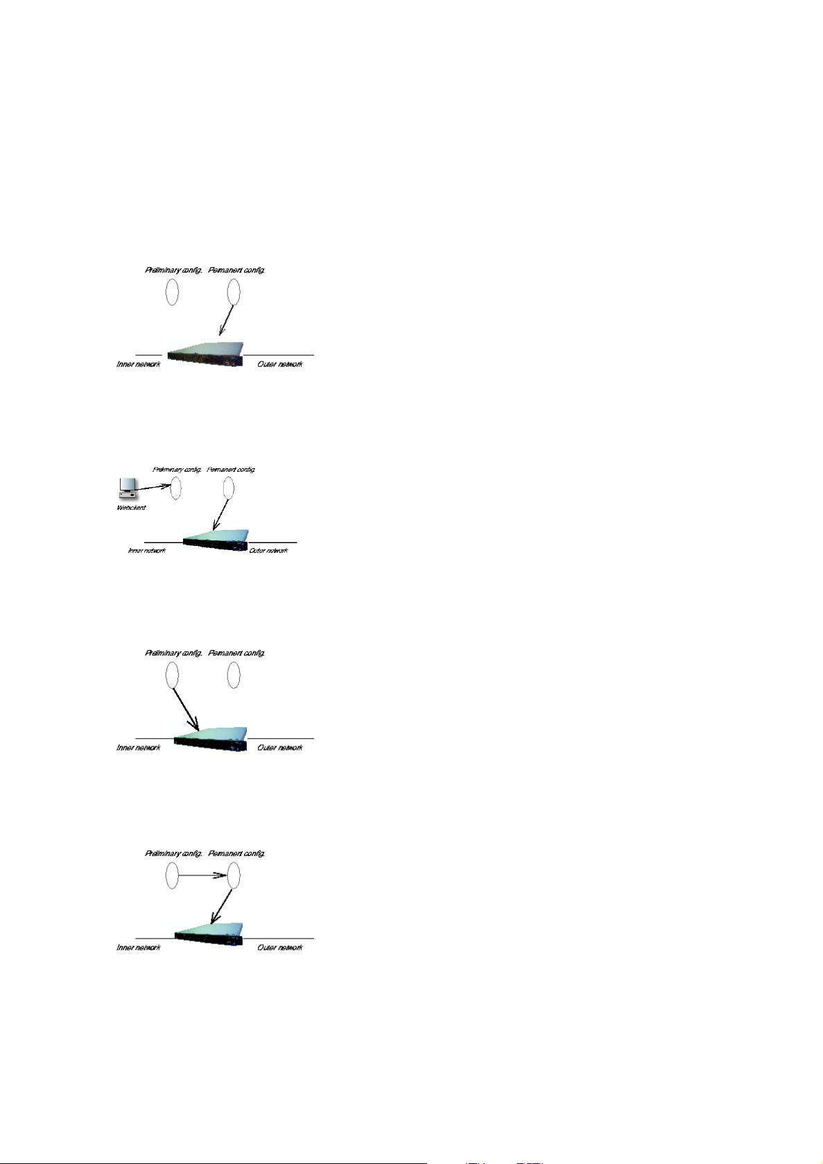
Preliminary and permanent configuration
3Com VCX IP Telecommuting Module has two kindsof settings: preliminary and permanent
configuration. When the Telecommuting Module is running, the permanent configuration
controls the Telecommuting Module functions.
When you configure your Telecommuting Module, you are working with the preliminary
configuration. As you change the preliminary configuration, the permanent configuration
continues to control the Telecommuting Module functions.
When you are done with the preliminary configuration, you can test it by selecting Apply
configuration on the Save/Load Configuration page. Now the preliminary configuration
controls the Telecommuting Module functions.
When you are satisfied with the preliminary configuration, you can apply it permanently,
which copies the preliminary configuration to the permanent configuration. Now the new
configuration controls the Telecommuting Module functions.
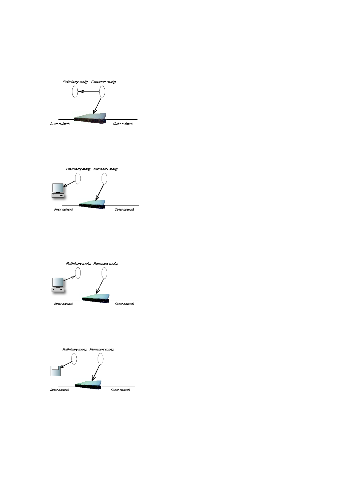
You can also copy the permanent configuration to the preliminary configuration. This does
not affect the permanent configuration or the Telecommuting Module functions, which are
21
Page 30
Chapter 3. Configuring 3Com VCX IP Telecommuting Module
still being run by the permanent configuration. You do this by selecting Abort all edits
on the Save/Load Configuration page under Administration. This will discard all changes
made in the preliminary configuration since last time you applied a configuration by pressing
Save configuration.
You can save the preliminary configuration to a file on your work station (the computer that
is running your web browser). Select Save to local file or Save config to CLI file on the
Save/Load Configuration page.
A saved configuration can be loaded to the preliminary configuration. Use Browse to search
your local computer or enter path and file name in the box. When you have chosen the file
you want to load, select Load from local file or Load CLI file on the Save/Load Configu-
ration page.
You can save the preliminary configuration to a diskette. Insert a formatted diskette in the
Telecommuting Module’s floppy drive and press Save to diskette on the Save/Load Con-
figuration page.
You can load a saved configuration to the preliminary configuration. Insert a diskette containing the saved configuration in the Telecommuting Module’s floppy drive and press Load
from diskette on the Save/Load Configuration page.
22
Page 31

Chapter 3. Configuring 3Com VCX IP Telecommuting Module
You can perform all of these functions on the Save/Load Configuration page under Administration.
Configuring IP addresses and masks in 3Com
VCX IP Telecommuting Module
IP address
IP addresses are written as four groups of numbers with dots between them. The numbers
must be between 0 and 255 (inclusive); for example, 192.168.129.17.
Mask/Bits
The binary system uses the numbers 0 and 1 to represent numbers. A binary digit is called a
bit. Eight bits in the binary system can represent numbers from 0 to 255.
The mask indicates how much of the IP address is used for the network address and the
computers’ individual addresses, respectively. A mask consists of 8+8+8+8 = 32 bits. Below
is a mask with 26 bits set to 1, which means that 26 bits of the IP address is locked to the
network address and can’t be changed within the network.
Bits 11111111 11111111 11111111 11000000
No. 255 255 255 192
In the 3Com VCX IP Telecommuting Module, a mask is written either as the number of bits
that are 1 or as four numbers (0-255) with dots between the numbers.
Sometimes it can be convenient to give a group of computers a network name, such as
Administration, or specify that only a handful of computers can change the Telecommuting
Module configuration.
You can form a group of computers with a network name, if the computers have consecutive
IP addresses. In order to do this, you must set the mask to indicate that the network group
consists of those computers only. The lowest IP address for these computers tells the network
number of the group.
This is easiest to explain with a simple example. You have 7 computers that will make up a
group called Administration.
Take the nearest power of two above the number of computers you want to include: 2, 4, 8,
16, 32, 64, 128 or 256. Since you have 7 computers, 8 is the nearest. In this example, one IP
address is free for future use.
Give the computers consecutive IP addresses. Make the first IP address a multiple of the
23
Page 32

Chapter 3. Configuring 3Com VCX IP Telecommuting Module
power of two number you selected, but under 255. In the above example, this means 0, 8,
16, 24, 32, 40, 48 and so on, up to 248. You might choose to start with 136 (17 x 8). This
would give the computers the IP addresses 196.176.1.136, 196.176.1.137, 196.176.1.138,
196.176.1.139, 196.176.1.140, 196.176.1.141, 196.176.1.142 and 196.176.1.143.
One of the IP addresses is free and can be used for an eighth computer in the future. You
must enter the first IP address in the series, 196.176.1.136, in the Network/IP address field.
Now you must set the mask so that only the computers with these eight IP addresses are in-
cluded in this network. Take 256 and subtract the number of IP addresses in the named network. In the example, we would have 256-8 = 248. The complete mask is 255.255.255.248.
Now you have created a group of computers (IP addresses) that you can give a single name,
such as Administration.
Table of netmasks.
No. of computers Mask Bits
1 255.255.255.255 32
2 255.255.255.254 31
4 255.255.255.252 30
8 255.255.255.248 29
16 255.255.255.240 28
32 255.255.255.224 27
64 255.255.255.192 26
128 255.255.255.128 25
256 255.255.255.0 24
See appendix C, Lists of Reserved Ports, ICMP Types and Codes, and Internet Protocols,
for more information on netmasks.
Name queries in 3Com VCX IP Telecommuting Module
A Telecommuting Module should be as independent of other computers as possible. At the
same time, the person who changes the configuration of the Telecommuting Module may
want to use names for the computers instead of IP addresses. Also, the SIP module needs to
look up names of SIP domains. This makes it necessary to use a DNS (name server) for SIP
requests.
There are three instances when 3Com VCX IP Telecommuting Module uses a DNS server:
• When it receives a SIP request for a SIP domain.
The results of these DNS queries are stored for a short while in the Telecommuting Module.
• When you change names/IP addresses and save the page.
24
Page 33

Chapter 3. Configuring 3Com VCX IP Telecommuting Module
The results of these DNS queries are stored in the Telecommuting Module.
• When you click on Look up all IP addresses again.
The results of these DNS queries are stored in the Telecommuting Module.
• When negotiations start for an IPsec tunnel where the IPsec peer has a dynamic DNS
name.
The results of these DNS queries are stored in the Telecommuting Module.
3Com VCX IP Telecommuting Module is dependent of a working name server for the SIP
functions. However, it doesn’t automatically look up IP addresses in the configuration, which
makes it necessary to click on Look up all IP addresses again every time a computer
changes its IP address.
When you enter IP addresses in the Telecommuting Module, they are not updated automatically. If you change a name/IP address in a row, the row is updated when you click on Save,
switch to another page of the Telecommuting Module user interface, or click on Look up
all IP addresses again.
25
Page 34

Chapter 3. Configuring 3Com VCX IP Telecommuting Module
26
Page 35

Part II. How To
In the How To part, you find step-by-step descriptions for many common configurations
for the Telecommuting Module. You also find references to relevant chapters in Part III,
Description of 3Com VCX IP Telecommuting Module settings.
Page 36

Page 37

Chapter 4. How To Configure SIP
3Com VCX IP Telecommuting Module provides a lot of SIP possibilities. In this chapter,
the most common SIP setups are setup with step-by-step instructions for the configuration.
DMZ Telecommuting Module, SIP server on the WAN
The simplest SIP scenario is when the SIP server is managed by someone else, and the
Telecommuting Module SIP function is only used to traverse NAT.
Note that the Telecommuting Module must have a public (non-NATed) IP address for the
SIP signaling to work correctly.
Here are the settings needed for this. It is assumed that the Telecommuting Module already
has a network configuration. Only the additional SIP settings are listed.
Networks and Computers
The Telecommuting Module must know the network structure to be able to function properly.
On the Networks and Computers page, you define all networks which the Telecommuting
Module should serve and which are not reached through the default gateway of the firewall.
All computers that can reach each other without having to go through the firewall connected
to the Telecommuting Module should be grouped in one network.
You can also define networks and parts of networks for other configuration purposes.
29
Page 38

Chapter 4. How To Configure SIP
Surroundings
To make the Telecommuting Module aware of the network structure, the networks defined
above should be listed on the Surroundings page.
Settings in the Surroundings table are only required when the Telecommuting Module has
been made the DMZ (or LAN) type.
The Telecommuting Module must know what the networks around it looks like. On this
page, you list all networks which the Telecommuting Module should serve and which are
not reached through the default gateway of the firewall.
All computers that can reach each other without having to go through the firewall connected
to the Telecommuting Module should be grouped in one network. When you are finished,
there should be one line for each of your firewall’s network connections (not counting the
default gateway).
One effect of this is that traffic between two users on different networks, or between one of
the listed networks and a network not listed here, is NAT:ed.
Another effect is that for connections between two users on the same network, or on networks where neither is listed in Surroundings, no ports for RTP sessions will be opened,
since the Telecommuting Module assumes that they are both on the same side of the firewall.
For DMZ and LAN SIParators, at least one network should be listed here. If no networks
are listed, the Telecommuting Module will not perform NAT for any traffic.
30
Page 39

Chapter 4. How To Configure SIP
Basic Settings
Go to the Basic Settings page under SIP Services and turn the SIP module on. Here you
also select log classes for SIP event logging.
Interoperability
You need to set the URI Encoding settings on the Interoperability page to "Use shorter,
encrypted URIs".
31
Page 40

Chapter 4. How To Configure SIP
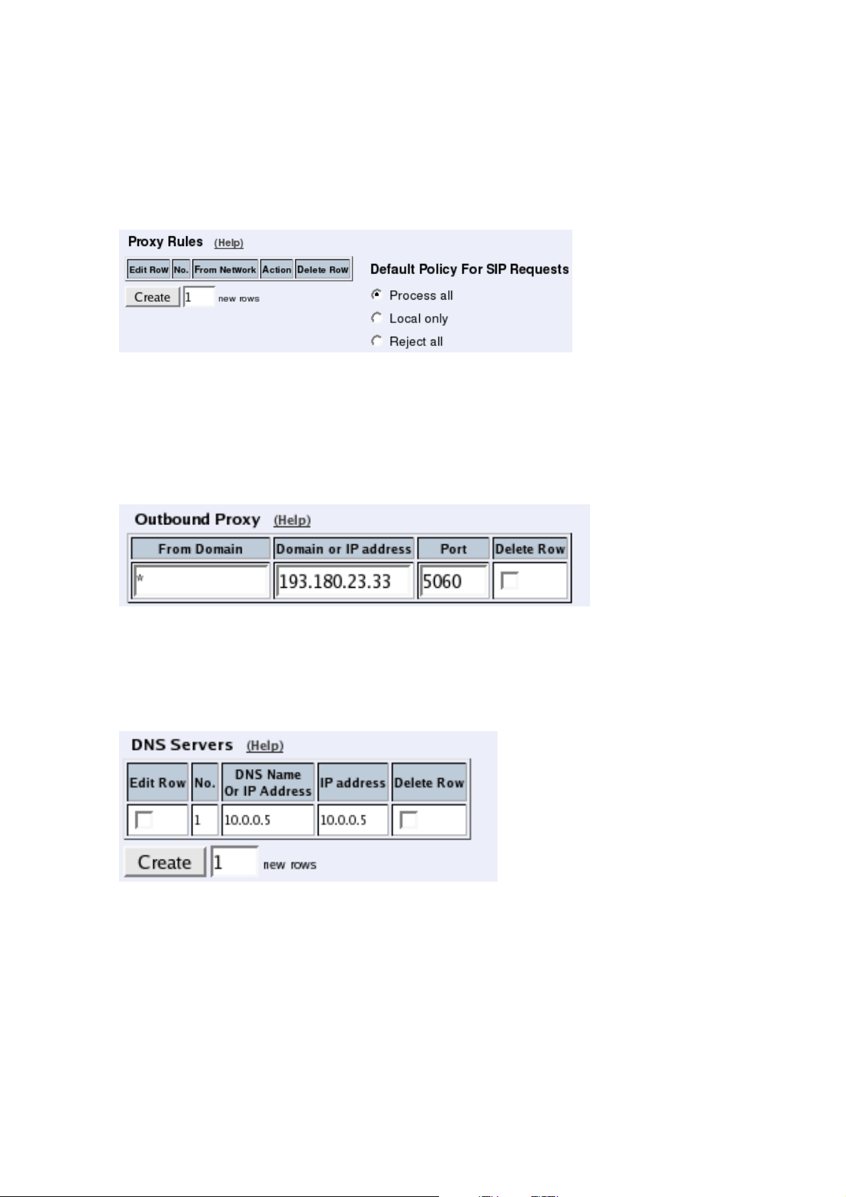
Filtering
To allow SIP traffic through the Telecommuting Module, you must change the Default Policy For SIP Requests on the Filtering page.
As the Telecommuting Module does not manage any SIP domains, there are no Local SIP
Domains. This means that you must select Process all for this setting.
Routing
On the Routing page, you can enter the SIP server managing your SIP domain. Enter the
name or IP address of the SIP server under Outbound proxy.
If you enter the server name here, all SIP traffic from the inside will be directed to this server,
regardless of where it is bound to.
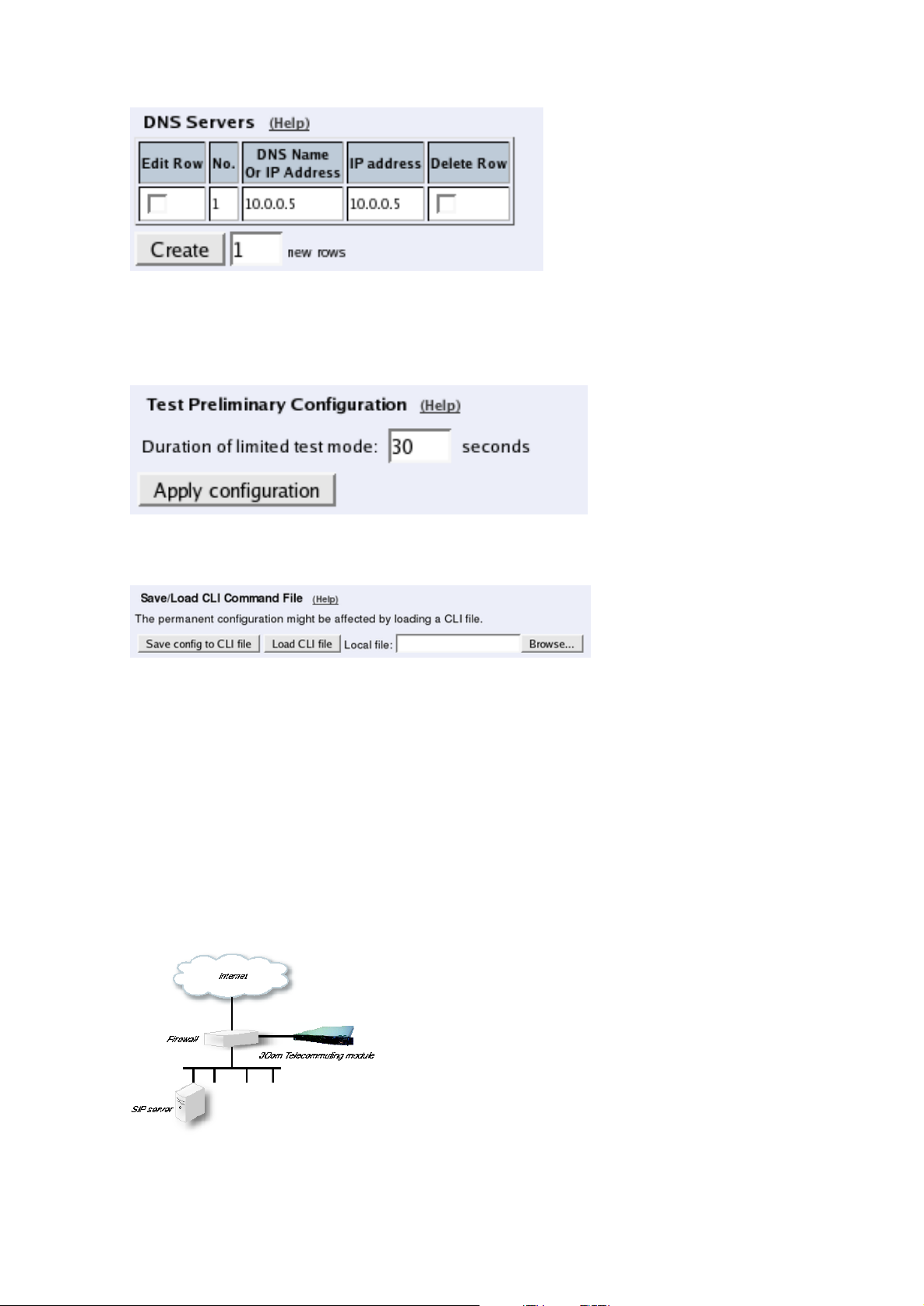
Basic Configuration
If no Outbound proxy is entered, the Telecommuting Module must be able to look up SIP
domains in DNS. DNS servers are entered on the Basic Configuration page under Basic
Configuration.
32
Page 41
Chapter 4. How To Configure SIP
Save/Load Configuration
Finally, go to the Save/Load Configuration page under Administration and apply the new
settings by pressing Apply configuration.
When the configuration has been applied, you should save a backup to file. Press Save config
to CLI file to save the configuration.
DMZ Telecommuting Module, SIP server on the LAN
For various reasons, you might want to use a separate SIP server instead of the built-in server
in the Telecommuting Module. That SIP server would be located on the inside or maybe on
a DMZ.
If the SIP server is located on a NATed network, DNS queries for the SIP domain should
point to the Telecommuting Module, which in turn will forward the SIP traffic to the server.
Note that the Telecommuting Module must have a public (non-NATed) IP address for the
SIP signaling to work correctly.
33
Page 42

Chapter 4. How To Configure SIP
Here are the settings needed for this. It is assumed that the Telecommuting Module already
has a network configuration. Only the additional SIP settings are listed.
Networks and Computers
The Telecommuting Module must know the network structure to be able to function properly.
On the Networks and Computers page, you define all networks which the Telecommuting
Module should serve and which are not reached through the default gateway of the firewall.
All computers that can reach each other without having to go through the firewall connected
to the Telecommuting Module should be grouped in one network.
You can also define networks and parts of networks for other configuration purposes.
Surroundings
To make the Telecommuting Module aware of the network structure, the networks defined
above should be listed on the Surroundings page.
Settings in the Surroundings table are only required when the Telecommuting Module has
been made the DMZ (or LAN) type.
The Telecommuting Module must know what the networks around it looks like. On this
page, you list all networks which the Telecommuting Module should serve and which are
not reached through the default gateway of the firewall.
All computers that can reach each other without having to go through the firewall connected
to the Telecommuting Module should be grouped in one network. When you are finished,
there should be one line for each of your firewall’s network connections (not counting the
default gateway).
34
Page 43

Chapter 4. How To Configure SIP
One effect of this is that traffic between two users on different networks, or between one of
the listed networks and a network not listed here, is NAT:ed.
Another effect is that for connections between two users on the same network, or on networks where neither is listed in Surroundings, no ports for RTP sessions will be opened,
since the Telecommuting Module assumes that they are both on the same side of the firewall.
For DMZ and LAN SIParators, at least one network should be listed here. If no networks
are listed, the Telecommuting Module will not perform NAT for any traffic.
Basic Settings
Go to the Basic Settings page under SIP Services and turn the SIP module on. Here you
also select log classes for SIP event logging.
35
Page 44

Chapter 4. How To Configure SIP
Routing
If the SIP server is located on a NATed network, all SIP traffic from the outside will be
directed to the Telecommuting Module, which must know where to forward it.
One way to do this is to enter the SIP domain in the DNS Override For SIP Requests table
on the Routing page, to link the SIP server IP address to the name. The Telecommuting
Module will look up the domain here instead of in the DNS server, and send the SIP traffic
to the correct IP address.
Interoperability
You need to set the URI Encoding settings on the Interoperability page to "Use shorter,
encrypted URIs".
Filtering
To allow SIP traffic through the Telecommuting Module, you must change the Default Policy For SIP Requests on the Filtering page.
As the Telecommuting Module does not manage any SIP domains, there are no Local SIP
Domains. This means that you must select Process all for this setting.
36
Page 45

Chapter 4. How To Configure SIP
Basic Configuration
If no Outbound proxy is entered, the Telecommuting Module must be able to look up SIP
domains in DNS. DNS servers are entered on the Basic Configuration page under Basic
Configuration.
Save/Load Configuration
Finally, go to the Save/Load Configuration page under Administration and apply the new
settings by pressing Apply configuration.
When the configuration has been applied, you should save a backup to file. Press Save config
to CLI file to save the configuration.
Standalone Telecommuting Module, SIP server on the WAN
The simplest SIP scenario is when the SIP server is managed by someone else, and the
Telecommuting Module SIP function is only used to traverse NAT.
Note that the Telecommuting Module must have a public (non-NATed) IP address for the
SIP signaling to work correctly.
37
Page 46

Chapter 4. How To Configure SIP
Here are the settings needed for this. It is assumed that the Telecommuting Module already
has a network configuration. Only the additional SIP settings are listed.
Basic Settings
Go to the Basic Settings page under SIP Services and turn the SIP module on. Here you
also select log classes for SIP event logging.
Interoperability
You need to set the URI Encoding settings on the Interoperability page to "Use shorter,
encrypted URIs".
38
Page 47

Chapter 4. How To Configure SIP
Filtering
To allow SIP traffic through the Telecommuting Module, you must change the Default Policy For SIP Requests on the Filtering page.
As the Telecommuting Module does not manage any SIP domains, there are no Local SIP
Domains. This means that you must select Process all for this setting.
Routing
On the Routing page, you can enter the SIP server managing your SIP domain. Enter the
name or IP address of the SIP server under Outbound proxy.
If you enter the server name here, all SIP traffic from the inside will be directed to this server,
regardless of where it is bound to.
Basic Configuration
If no Outbound proxy is entered, the Telecommuting Module must be able to look up SIP
domains in DNS. DNS servers are entered on the Basic Configuration page under Basic
Configuration.
39
Page 48

Chapter 4. How To Configure SIP
Save/Load Configuration
Finally, go to the Save/Load Configuration page under Administration and apply the new
settings by pressing Apply configuration.
When the configuration has been applied, you should save a backup to file. Press Save config
to CLI file to save the configuration.
Client Settings
SIP clients will use the Telecommuting Module as their outgoing SIP proxy and the SIP
domain as the registrar.
Standalone Telecommuting Module, SIP server on the LAN
For various reasons, you might want to use a separate SIP server instead of the built-in server
in the Telecommuting Module. That SIP server would be located on the inside or maybe on
a DMZ.
If the SIP server is located on a NATed network, DNS queries for the SIP domain should
point to the Telecommuting Module, which in turn will forward the SIP traffic to the server.
Note that the Telecommuting Module must have a public (non-NATed) IP address for the
SIP signaling to work correctly.
40
Page 49

Chapter 4. How To Configure SIP
Here are the settings needed for this. It is assumed that the Telecommuting Module already
has a network configuration. Only the additional SIP settings are listed.
Basic Settings
Go to the Basic Settings page under SIP Services and turn the SIP module on. Here you
also select log classes for SIP event logging.
Routing
If the SIP server is located on a NATed network, all SIP traffic from the outside will be
directed to the Telecommuting Module, which must know where to forward it.
One way to do this is to enter the SIP domain in the DNS Override For SIP Requests table
on the Routing page, to link the SIP server IP address to the name. The Telecommuting
41
Page 50

Chapter 4. How To Configure SIP
Module will look up the domain here instead of in the DNS server, and send the SIP traffic
to the correct IP address.
Interoperability
You need to set the URI Encoding settings on the Interoperability page to "Use shorter,
encrypted URIs".
Filtering
To allow SIP traffic through the Telecommuting Module, you must change the Default Policy For SIP Requests on the Filtering page.
As the Telecommuting Module does not manage any SIP domains, there are no Local SIP
Domains. This means that you must select Process all for this setting.
Basic Configuration
If no Outbound proxy is entered, the Telecommuting Module must be able to look up SIP
domains in DNS. DNS servers are entered on the Basic Configuration page under Basic
Configuration.
42
Page 51

Chapter 4. How To Configure SIP
Save/Load Configuration
Finally, go to the Save/Load Configuration page under Administration and apply the new
settings by pressing Apply configuration.
When the configuration has been applied, you should save a backup to file. Press Save config
to CLI file to save the configuration.
Client Settings
SIP clients will use the Telecommuting Module as their outgoing SIP proxy and the SIP
domain as the registrar.
DMZ/LAN Telecommuting Module, SIP server on the WAN
The simplest SIP scenario is when the SIP server is managed by someone else, and the
Telecommuting Module SIP function is only used to traverse NAT.
Note that the Telecommuting Module must have a public (non-NATed) IP address for the
SIP signaling to work correctly.
43
Page 52

Chapter 4. How To Configure SIP
Here are the settings needed for this. It is assumed that the Telecommuting Module already
has a network configuration. Only the additional SIP settings are listed.
Basic Settings
Go to the Basic Settings page under SIP Services and turn the SIP module on. Here you
also select log classes for SIP event logging.
Interoperability
You need to set the URI Encoding settings on the Interoperability page to "Use shorter,
encrypted URIs".
44
Page 53
Chapter 4. How To Configure SIP
Filtering
To allow SIP traffic through the Telecommuting Module, you must change the Default Policy For SIP Requests on the Filtering page.
As the Telecommuting Module does not manage any SIP domains, there are no Local SIP
Domains. This means that you must select Process all for this setting.
Routing
On the Routing page, you can enter the SIP server managing your SIP domain. Enter the
name or IP address of the SIP server under Outbound proxy.
If you enter the server name here, all SIP traffic from the inside will be directed to this server,
regardless of where it is bound to.
Basic Configuration
If no Outbound proxy is entered, the Telecommuting Module must be able to look up SIP
domains in DNS. DNS servers are entered on the Basic Configuration page under Basic
Configuration.
Save/Load Configuration
Finally, go to the Save/Load Configuration page under Administration and apply the new
settings by pressing Apply configuration.
45
Page 54

Chapter 4. How To Configure SIP
When the configuration has been applied, you should save a backup to file. Press Save config
to CLI file to save the configuration.
Client Settings
SIP clients will use the Telecommuting Module as their outgoing SIP proxy and the SIP
domain as the registrar.
DMZ/LAN Telecommuting Module, SIP server on the LAN
For various reasons, you might want to use a separate SIP server instead of the built-in server
in the Telecommuting Module. That SIP server would be located on the inside or maybe on
a DMZ.
If the SIP server is located on a NATed network, DNS queries for the SIP domain should
point to the Telecommuting Module, which in turn will forward the SIP traffic to the server.
Note that the Telecommuting Module must have a public (non-NATed) IP address for the
SIP signaling to work correctly.
Here are the settings needed for this. It is assumed that the Telecommuting Module already
has a network configuration. Only the additional SIP settings are listed.
Basic Settings
Go to the Basic Settings page under SIP Services and turn the SIP module on. Here you
also select log classes for SIP event logging.
46
Page 55

Chapter 4. How To Configure SIP
Routing
If the SIP server is located on a NATed network, all SIP traffic from the outside will be
directed to the Telecommuting Module, which must know where to forward it.
One way to do this is to enter the SIP domain in the DNS Override For SIP Requests table
on the Routing page, to link the SIP server IP address to the name. The Telecommuting
Module will look up the domain here instead of in the DNS server, and send the SIP traffic
to the correct IP address.
Interoperability
You need to set the URI Encoding settings on the Interoperability page to "Use shorter,
encrypted URIs".
47
Page 56

Chapter 4. How To Configure SIP
Filtering
To allow SIP traffic through the Telecommuting Module, you must change the Default Policy For SIP Requests on the Filtering page.
As the Telecommuting Module does not manage any SIP domains, there are no Local SIP
Domains. This means that you must select Process all for this setting.
Basic Configuration
If no Outbound proxy is entered, the Telecommuting Module must be able to look up SIP
domains in DNS. DNS servers are entered on the Basic Configuration page under Basic
Configuration.
Save/Load Configuration
Finally, go to the Save/Load Configuration page under Administration and apply the new
settings by pressing Apply configuration.
48
Page 57

Chapter 4. How To Configure SIP
When the configuration has been applied, you should save a backup to file. Press Save config
to CLI file to save the configuration.
Client Settings
SIP clients will use the Telecommuting Module as their outgoing SIP proxy and the SIP
domain as the registrar.
LAN Telecommuting Module
For various reasons, you might want to use a separate SIP server instead of the built-in server
in the Telecommuting Module. That SIP server would be located on the inside or maybe on
a DMZ.
With the LAN Telecommuting Module, you connect the Telecommuting Module to a NATed
network.
Here are the settings needed for this. It is assumed that the Telecommuting Module already
has a network configuration. Only the additional SIP settings are listed.
Networks and Computers
The Telecommuting Module must know the network structure to be able to function properly.
On the Networks and Computers page, you define all networks which the Telecommuting
Module should serve and which are not reached through the default gateway of the firewall.
49
Page 58

Chapter 4. How To Configure SIP
All computers that can reach each other without having to go through the firewall connected
to the Telecommuting Module should be grouped in one network.
You can also define networks and parts of networks for other configuration purposes.
Surroundings
To make the Telecommuting Module aware of the network structure, the networks defined
above should be listed on the Surroundings page.
Settings in the Surroundings table are only required when the Telecommuting Module has
been made the DMZ (or LAN) type.
The Telecommuting Module must know what the networks around it looks like. On this
page, you list all networks which the Telecommuting Module should serve and which are
not reached through the default gateway of the firewall.
All computers that can reach each other without having to go through the firewall connected
to the Telecommuting Module should be grouped in one network. When you are finished,
there should be one line for each of your firewall’s network connections (not counting the
default gateway).
One effect of this is that traffic between two users on different networks, or between one of
the listed networks and a network not listed here, is NAT:ed.
Another effect is that for connections between two users on the same network, or on networks where neither is listed in Surroundings, no ports for RTP sessions will be opened,
since the Telecommuting Module assumes that they are both on the same side of the firewall.
For DMZ and LAN SIParators, at least one network should be listed here. If no networks
are listed, the Telecommuting Module will not perform NAT for any traffic.
Basic Settings
Go to the Basic Settings page under SIP Services and turn the SIP module on. Here you
also select log classes for SIP event logging.
50
Page 59

Chapter 4. How To Configure SIP
Filtering
To allow SIP traffic through the Telecommuting Module, you must change the Default Policy For SIP Requests on the Filtering page.
As the Telecommuting Module does not manage any SIP domains, there are no Local SIP
Domains. This means that you must select Process all for this setting.
Basic Configuration
The Telecommuting Module must be able to look up SIP domains in DNS. DNS servers are
entered on the Basic Configuration page under Basic Configuration.
51
Page 60

Chapter 4. How To Configure SIP
Remote SIP Connectivity
If you have remote SIP clients behind other NAT boxes, you need to activate Remote NAT
Traversal.
Interoperability
You need to set the URI Encoding settings on the Interoperability page to "Use shorter,
encrypted URIs".
You need to enter the public IP that corresponds to the Telecommuting Module under Pub-
lic IP address for NATed Telecommuting Module. This will make the Telecommuting
Module able to rewrite outgoing SIP packets properly.
Save/Load Configuration
Finally, go to the Save/Load Configuration page under Administration and apply the new
settings by pressing Apply configuration.
52
Page 61

Chapter 4. How To Configure SIP
When the configuration has been applied, you should save a backup to file. Press Save config
to CLI file to save the configuration.
The Firewall
The firewall in front of the LAN Telecommuting Module must be configured in this way:
• There must be a static IP address that can be mapped to the Telecommuting Module’s
private IP address. All traffic to this IP address must be forwarded to the SIParator.
• When the firewall forwards traffic to the Telecommuting Module, it must not NAT this
traffic, i.e. the Telecommuting Module needs to see the original sender IP address.
• All outgoing traffic from the Telecommuting Module should be allowed through the fire-
wall.
• For outgoing traffic from the Telecommuting Module, the firewall needs to use the same IP
address as above when performing NAT. If another IP address is used, some SIP signalling
will go awry, and Remote SIP Connectivity will not always work properly.
• For outgoing traffic from the Telecommuting Module the firewall must not change sender
port when performing NAT. If it does change port, Remote SIP Connectivity will not
always work properly.
53
Page 62

Chapter 4. How To Configure SIP
54
Page 63

Chapter 5. How To Configure
Advanced SIP
3Com VCX IP Telecommuting Module provides a lot of SIP possibilities. In this chapter,
some advanced SIP setups will be presented with step-by-step instructions for the configuration.
How To Use Your SIP Operator Account Via 3Com VCX IP Telecommuting Module
This is how to configure your Telecommuting Module to register at your SIP operator, and
to use that SIP account for your local users.
This feature is only available when the Advanced SIP Routing or the SIP Trunking module
has been installed.
Enter your SIP operator account on the Local Registrar page. You enter the username and
password from the operator, and select the XF/Register account type. This account type will
make the Telecommuting Module register at the SIP operator with the credentials you enter.
Some operators don’t require registration. In this case, select the XF account type instead.
You can select any network in the Register from field, as it is not used for these account
types.
Outgoing Calls
For outgoing calls, you have to define when your SIP operator account should be used.
Usually, you use this type of account to call to the PSTN network ("ordinary telephones").
On the Dial Plan page, you define what type of calls should be redirected to your SIP
operator. First, turn the Dial Plan on.
55
Page 64

Chapter 5. How To Configure Advanced SIP
Show One Number When Calling
You can select to show one single calling number regardless of which user makes the call.
This is useful when you want others to use your Answering service/Auto Attendant when
calling back to you.
In the Matching From Header table, you define from which network the calls can come.
You can also select what the From header (that tells who is calling) should look like. This is
used when matching requests in the Dial Plan table below. Name each definition properly,
to make it easier to use further on.
In the Matching Request-URI table, you define callees. This is used when matching requests in the Dial Plan table below.
In this case, you want to define the calls that should be routed to your SIP operator, which
is call destinations where the usernames consist of numbers only, as these most likely are
intended to go to the PSTN network. Call destinations that look like helen@sip.ingate.com
should not be routed via the SIP operator, but be handled by the Telecommuting Module
itself.
You can let users call international numbers with a + sign instead of the international prefix.
For this, define the + sign as a Prefix, which means that it will be stripped before the call is
forwarded.
The Min. Tail is set to 4 here, to open for the possibility of three-digit local extensions,
which should not be handled by the Dial Plan.
In the Forward To table, you define where calls should be forwarded. This is used in the
Dial Plan table below.
In this case, the calls should be forwarded to your SIP operator account that was defined
before. You select the account under Account.
The calls can also be forwarded to your SIP operator using the operator’s IP address in the
Replacement URI field.
56
Page 65
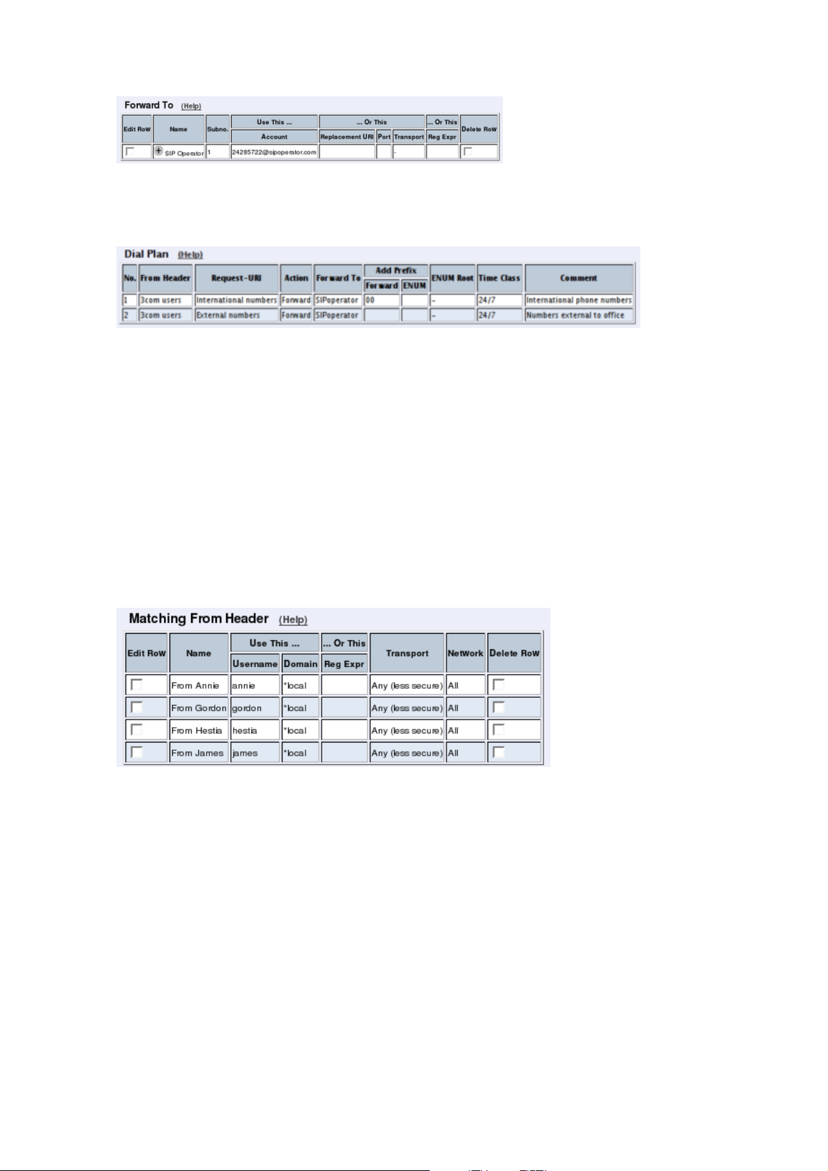
Chapter 5. How To Configure Advanced SIP
At last, you combine these definitions in the Dial Plan table. Make one line for international
calls and one for other calls, because we need to add the international prefix for international
calls only.
Now, when a local user calls an external phone number, the Telecommuting Module will
route this call to your SIP operator and rewrite the signaling to use your SIP operator account.
Show Different Numbers When Calling
You can select to show different calling numbers based on which user makes the call. This is
useful when you want to let the called person use number presentation to see who is calling.
In the Matching From Header table, you define from which network the calls can come.
You can also select what the From header (that tells who is calling) should look like. This is
used when matching requests in the Dial Plan table below. Name each definition properly,
to make it easier to use further on.
Create one row per user. These will be used to present the correct calling number for the
called user.
In the Matching Request-URI table, you define callees. This is used when matching requests in the Dial Plan table below.
In this case, you want to define the calls that should be routed to your SIP operator, which
is call destinations where the usernames consist of numbers only, as these most likely are
intended to go to the PSTN network. Call destinations that look like helen@sip.ingate.com
should not be routed via the SIP operator, but be handled by the Telecommuting Module
itself.
You can let users call international numbers with a + sign instead of the international prefix.
For this, define the + sign as a Prefix, which means that it will be stripped before the call is
forwarded.
The Min. Tail is set to 4 here, to open for the possibility of three-digit local extensions,
which should not be handled by the Dial Plan.
57
Page 66

Chapter 5. How To Configure Advanced SIP
In the Forward To table, you define where calls should be forwarded. This is used in the
Dial Plan table below.
In this case, calls from one user should be forwarded to the corresponding SIP operator
account. Create one row per user and select the account under Account.
At last, you combine these definitions in the Dial Plan table. For each user, make one line
for international calls and one for other calls, because we need to add the international prefix
for international calls only.
Now, when a local user calls an external phone number, the Telecommuting Module will
route this call to your SIP operator and rewrite the signaling to use your SIP operator account.
Incoming Calls
For incoming calls, there are two different ways of forwarding the calls to your SIP server;
either via the Dial Plan or via the User Routing table. Which one should be used depends
on how the operator sends out your calls.
If they just send them out as number@yourdomain.com, you should use the Dial Plan. If
they use the Contact information in the registration, you should use the User Routing.
If you use the Dial Plan, you need to add some more settings on the Dial Plan page.
First, add a row in the Matching From Header table to match incoming calls.
58
Page 67

Chapter 5. How To Configure Advanced SIP
Then, match on the incoming phone number and domain in the Matching Request-URI
table. The Domain will usually be the public IP address of the Telecommuting Module.
If the operator uses a ’+’ in front of the phone number and your SIP server doesn’t want that,
enter ’+’ in the Prefix field. This will make the Telecommuting Module strip the ’+’ before
forwarding the call.
Enter the SIP server in the Forward To table.
Combine these in the Forward To table.
If you use User Routing, you need to add a forwarding address for each of the SIP operator
accounts you have.
Note that you can only use the User Routing table for incoming call forwarding. The Static
Registrations should not be used when XF or XF/Register accounts are involved.
Finally, go to the Save/Load Configuration page under Administration and apply the new
settings by pressing Apply configuration.
59
Page 68

Chapter 5. How To Configure Advanced SIP
How To Use Your SIP Operator Account and
Your IP-PBX Via 3Com VCX IP Telecommuting
Module
This is how to configure your Telecommuting Module to forward requests between your SIP
operator and your local IP-PBX.
The configuration varies slightly depending on if the operator uses accounts or IP addresses
for the authentication.
This feature is only available when the Advanced SIP Routing or the SIP Trunking module
has been installed.
Instead of configuring this manually, you can use the 3Com Startup Tool, which can be found
at http://www.ingate.com/Startup_Tool.php.
Outgoing Calls
Authentication by Accounts a.k.a SIP Trunk via SIP accounts
Enter your SIP operator account on the Local Registrar page. You enter the username and
password from the operator, and select the XF/Register account type. This account type will
make the Telecommuting Module register at the SIP operator with the credentials you enter.
Some operators don’t require registration. In this case, select the XF account type instead.
You can select any network in the Register from field, as it is not used for these account
types.
For outgoing calls, you have to define when your SIP operator account should be used.
Usually, you use this type of account to call to the PSTN network ("ordinary telephones").
On the Dial Plan page, you define what type of calls should be redirected to your SIP
operator. First, turn the Dial Plan on.
60
Page 69

Chapter 5. How To Configure Advanced SIP
In the Matching From Header table, you define from which network the calls can come.
You can also select what the From header (that tells who is calling) should look like. This is
used when matching requests in the Dial Plan table below. Name each definition properly,
to make it easier to use further on.
In this case, we want to match on calls coming from the IP-PBX. This will ensure that only
users who have been autorized by the PBX to use the SIP trunk will be able to make outgoing
calls.
In the Matching Request-URI table, you define callees. This is used when matching requests in the Dial Plan table below.
In this case, you want to define the calls that should be routed to your SIP operator, which
is call destinations where the usernames consist of numbers only, as these most likely are
intended to go to the PSTN network. Call destinations that look like helen@sip.ingate.com
should not be routed via the SIP operator, but be handled by the Telecommuting Module
itself.
You can let users call international numbers with a + sign instead of the international prefix.
For this, define the + sign as a Prefix, which means that it will be stripped before the call is
forwarded.
The Min. Tail is set to 4 here, to open for the possibility of three-digit local extensions,
which should not be handled by the Dial Plan.
In the Forward To table, you define where calls should be forwarded. This is used in the
Dial Plan table below.
61
Page 70

Chapter 5. How To Configure Advanced SIP
In this case, the calls should be forwarded to your SIP operator account that was defined
before. You select the account under Account.
The calls can also be forwarded to your SIP operator using the operator’s IP address in the
Replacement URI field.
At last, you combine these definitions in the Dial Plan table. Make one line for international
calls and one for other calls, because we need to add the international prefix for international
calls only.
Now, when a local user calls an external phone number, the Telecommuting Module will
route this call to your SIP operator and rewrite the signaling to use your SIP operator account.
Authentication by IP Addresses a.k.a SIP Trunk via IP address
On the Dial Plan page, you define what type of calls should be redirected to your SIP
operator. First, turn the Dial Plan on.
In the Matching From Header table, you define from which network the calls can come.
You can also select what the From header (that tells who is calling) should look like. This is
used when matching requests in the Dial Plan table below. Name each definition properly,
to make it easier to use further on.
62
Page 71

Chapter 5. How To Configure Advanced SIP
In the Matching Request-URI table, you define callees. This is used when matching requests in the Dial Plan table below.
In this case, you want to define the calls that should be routed to your SIP operator, which
is call destinations where the usernames consist of numbers only, as these most likely are
intended to go to the PSTN network. Call destinations that look like helen@sip.ingate.com
should not be routed via the SIP operator, but be handled by the Telecommuting Module
itself.
You can let users call international numbers with a + sign instead of the international prefix.
For this, define the + sign as a Prefix, which means that it will be stripped before the call is
forwarded.
The Min. Tail is set to 4 here, to open for the possibility of three-digit local extensions,
which should not be handled by the Dial Plan.
In the Forward To table, you define where calls should be forwarded. This is used in the
Dial Plan table below.
In this case, the calls should be forwarded to your SIP operator account that was defined
before. You select the account under Account.
The calls can also be forwarded to your SIP operator using the operator’s IP address in the
Replacement URI field.
At last, you combine these definitions in the Dial Plan table. Make one line for international
calls and one for other calls, because we need to add the international prefix for international
calls only.
63
Page 72

Chapter 5. How To Configure Advanced SIP
Now, when a local user calls an external phone number, the Telecommuting Module will
route this call to your SIP operator and rewrite the signaling to use your SIP operator account.
Incoming Calls
All incoming calls from the operator should be forwarded to the PBX. This is done on the
Dial Plan page.
On the Dial Plan page, you define what type of calls should be redirected to your SIP
operator. First, turn the Dial Plan on.
In the Matching From Header table, you define from which network the calls can come.
You can also select what the From header (that tells who is calling) should look like. This is
used when matching requests in the Dial Plan table below. Name each definition properly,
to make it easier to use further on.
In this case, we only need to define the operator by its sending network.
In the Matching Request-URI table, you define callees. This is used when matching requests in the Dial Plan table below.
In this case, you want to define the calls that should be routed to your PBX, which is call
destinations where the usernames consist of numbers only. For extra matching, enter the
outside IP address of the Telecommuting Module, which the operator will be using.
64
Page 73

Chapter 5. How To Configure Advanced SIP
In the Forward To table, you define where calls should be forwarded. This is used in the
Dial Plan table below.
In this case, the calls should be forwarded to your SIP operator account that was defined
before. You select the account under Account.
Enter the IP address of the IP-PBX in the Replacement URI field. This will make the
Telecommuting Module replace the domain part in the incoming call with this IP address.
The username part of the URI will be kept.
At last, you combine these definitions in the Dial Plan table. Select the operator and the
Request-URI, and forward to the PBX.
Finally, go to the Save/Load Configuration page under Administration and apply the new
settings by pressing Apply configuration.
How To Use Multiple SIP Operators or
IP-PBXs Via 3Com VCX IP Telecommuting
Module
This is how to configure your Telecommuting Module to forward requests between your SIP
operator and your local IP-PBX.
The configuration varies slightly depending on if the operator uses accounts or IP addresses
for the authentication.
This description is targeted for multiple operators or PBXs where the Telecommuting Module selects destination based on the called number and the caller.
This feature is only available when the Advanced SIP Routing or the SIP Trunking module
has been installed.
65
Page 74

Chapter 5. How To Configure Advanced SIP
Multiple Operators (Least Cost Routing)
If any of the SIP operators use accounts, enter that on the Local Registrar page. You enter
the username and password from the operator, and select the XF/Register account type. This
account type will make the Telecommuting Module register at the SIP operator with the
credentials you enter.
Some operators don’t require registration. In this case, select the XF account type instead.
You can select any network in the Register from field, as it is not used for these account
types.
On the Dial Plan page, you define what type of calls should be redirected to your SIP
operator. First, turn the Dial Plan on.
In the Matching From Header table, you define from which network the calls can come.
You can also select what the From header (that tells who is calling) should look like. This is
used when matching requests in the Dial Plan table below. Name each definition properly,
to make it easier to use further on.
In this office, there is a group of phones that always put a "+" first in the phone number when
dialing a non-US number. We need to match on these to handle them specially.
In the Matching Request-URI table, you define callees. This is used when matching requests in the Dial Plan table below.
In this case, you want to sort out calls that should be routed to the different operators. You
might have a UK operator and a US operator, and thus you want to be able to recognize these
calls.
66
Page 75

Chapter 5. How To Configure Advanced SIP
The basic way of recognizing calls is to check the country code, which is the first part of
the phone number. In the table, there are three rows for matching UK calls. The two "UK
numbers 00" rows give the same result, as does the two "US numbers" rows. The 10.47.2.243
IP address is that of the Telecommuting Module itself.
The ".*" expression in the Reg Expr fields match 0 or more characters of any kind. The
parantheses show how much of the incoming Request-URI we want to keep when forwarding
the request.
In the Forward To table, you define where calls should be forwarded. This is used in the
Dial Plan table below.
In this case, define your two SIP operators. One may use accounts and the other IP addresses
for authentication.
The two "UK Operator" rows are nearly the same.
With the "UK Operator" row, the Request-URI in the incoming call will have the domain
part replaced with what is entered in the Replacement URI field. The username part of the
URI will be kept.
With the "UK Operator regexp" row, the Telecommuting Module will get whatever was in
the first set of parantheses in the Matching Request-URI table, and use that as the username part. The domain part is "sipoperator.co.uk;b2bua". The ";b2bua" parameter makes
the Telecommuting Module handle all REFER requests itself; instead of forwarding them.
This can be useful as many operators do not support the REFER method, which is used for
call transfers.
At last, you combine these definitions in the Dial Plan table.
For UK calls, the operator requires that the phone number begins with "00", which means
that some calls can be forwarded directly (row 2), but for calls where the number starts with
"+", this has to be replaced with "00" (row 3). This means the calls that originate from the
"+ phones".
For US calls, use any of the defined US Request-URIs, and forward to the US operator.
Note that if you want to use a Reg Expr definition for Forward To, you also need to use a
Reg Expr definition for the Request-URI.
67
Page 76
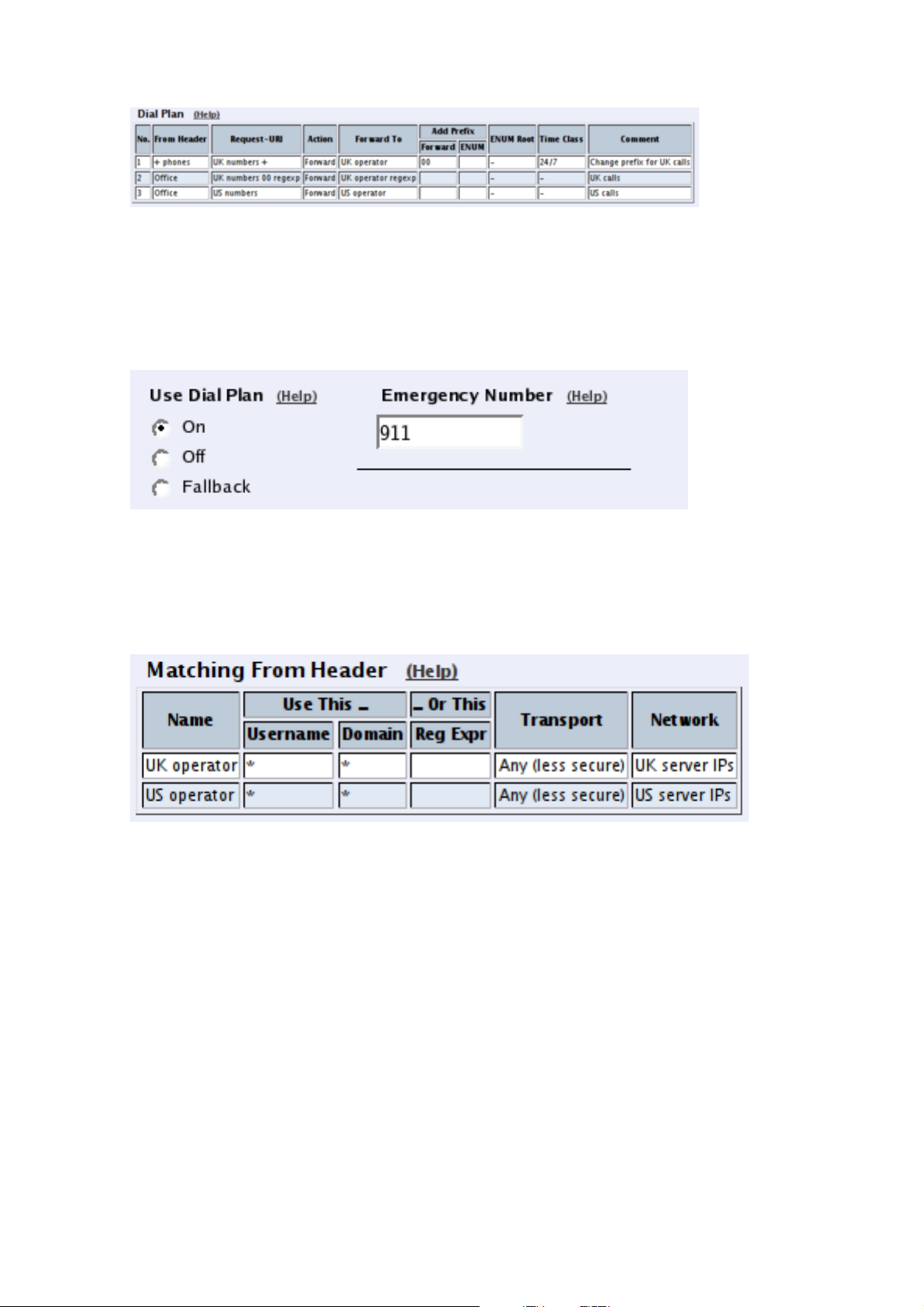
Chapter 5. How To Configure Advanced SIP
Multiple PBXs
If you have multiple PBXs on the inside, you might want to send calls to different servers
based on the sender or the called number.
On the Dial Plan page, you define which calls should be redirected to which PBX. First,
turn the Dial Plan on.
In the Matching From Header table, you define from which network the calls can come.
You can also select what the From header (that tells who is calling) should look like. This is
used when matching requests in the Dial Plan table below. Name each definition properly,
to make it easier to use further on.
In this case, we define one entry for each operator.
In the Matching Request-URI table, you define callees. This is used when matching requests in the Dial Plan table below.
In this case, you want to sort out which calls go to which PBX.
Assuming that each PBX manage a phone number range where the leading digits are differ-
ent, it is easy to make matching definitions.
As the UK operator will send phone numbers that start with a "1", we allow for that, but by
putting the "1" in the Prefix column, it will be stripped from the phone number when the
Telecommuting Module forwards the call.
68
Page 77

Chapter 5. How To Configure Advanced SIP
The same matching definitions can be made with regular expressions. Here, each number
range only needs one definition, as the "?" sign marks that the previous character can appear
0 or 1 times. The part of the number that we want to forward should be within parantheses.
In the Forward To table, you define where calls should be forwarded. This is used in the
Dial Plan table below.
In this case, define your two PBXs, simply by entering their respective IP addresses in the
Replacement URI field.
The same forwarding definitions can be made with regular expressions. The "$1" expression
collects the number that matched the expression inside the parantheses in the Matching
Request-URI table.
At last, you combine these definitions in the Dial Plan table.
Select the operator, range, and then select to which PBX to send this call.
69
Page 78

Chapter 5. How To Configure Advanced SIP
If regular expressions were used, you only need one line per PBX. As the expressions were
designed to match calls from both operators, you don’t need to select an operator here.
Finally, go to the Save/Load Configuration page under Administration and apply the new
settings by pressing Apply configuration.
How To Use RADIUS Accounting with 3Com VCX IP Telecommuting Module
This is how to configure your Telecommuting Module to use RADIUS Accounting for calls
to or from local users.
If you are only interested in accounting for calls to other domains, you only have to turn the
RADIUS Accounting on.
If you want to bill for local calls too, you will have to force the users to go via the Telecommuting Module even when they are both on the same side. For this, the Telecommuting
Module will have to act as a back-to-back user agent (B2BUA) for all calls.
This feature is only available when the Advanced SIP Routing or the SIP Trunking module
has been installed.
First, define the RADIUS server to receive accounting ticks. This is done on the RADIUS
page. If the RADIUS server should only be used for accounting, you can enter any port
number in the table. The Telecommuting Module will use port 1813 for accounting.
If you use the Telecommuting Module as the SIP registrar, and the RADIUS server should
be used for SIP authentication as well, you need to enter the port number on which the
70
Page 79
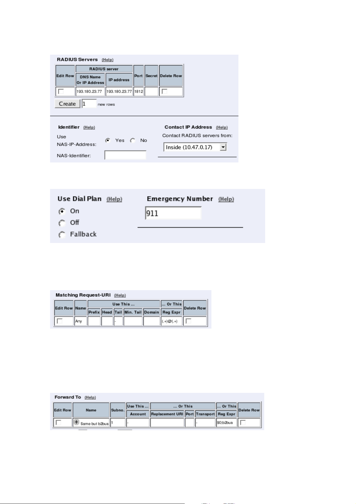
Chapter 5. How To Configure Advanced SIP
RADIUS server listens for authentication requests (usually ports 1812 or 1645).
On the Dial Plan page, you define how calls should be routed through the Telecommuting
Module. First, turn the Dial Plan on.
In the Matching Request-URI table, you define call destinations. This is used when matching requests in the Dial Plan table below.
In this case, you want to define a Reg Exp (regular expression) which matches all RequestURIs. Enter "(.+)@(.+)" in the Reg Exp field.
In the Forward To table, you define where calls should be forwarded. This is used in the
Dial Plan table below.
In this case, the calls should be forwarded to their original destination, but the Telecommuting Module should forward them as a B2BUA. Enter "$0;b2bua" in the Reg Exp field. This
will reuse the incoming Request-URI, but make the Telecommuting Module act as a B2BUA
instead of a proxy.
71
Page 80

Chapter 5. How To Configure Advanced SIP
At last, you combine these definitions in the Dial Plan table. Make a new row in the table
and select the definitions from the tables above.
Now, when a SIP user calls another SIP user, the Telecommuting Module will step in and
always stay in the path for the call. Both SIP clients will signal to the Telecommuting Module
only, and the Telecommuting Module will forward signaling between them. Media will still
go directly between the clients.
Finally, go to the Save/Load Configuration page under Administration and apply the new
settings by pressing Apply configuration.
72
Page 81

Part III. Description of 3Com
VCX IP Telecommuting Module
Settings
This part contains complete descriptions of settings in the 3Com VCX IP Telecommuting
Module GUI. The descriptions are grouped in the same way as they are in the GUI.
Page 82

Page 83

Chapter 6. Basic Configuration
Under Basic Configuration, you configure:
• Telecommuting Module Type
• The name of the Telecommuting Module
• The computers and networks from which the Telecommuting Module can be administered
• Policies for ping packets and unwanted packets
• Default domain
• DNS servers
• RADIUS configuration
• SNMP configuration
• If the Telecommuting Module should use external services to update a DNS server dy-
namically when the Telecommuting Module changes its own IP address.
• Creation of Telecommuting Module certificates and upload of CA certificates
This configuration is usually not changed very often.
Basic Configuration
On the Basic Configuration page, general settings for the Telecommuting Module are made.
The most important one for getting started is the DNS server.
General
Name of this Telecommuting Module
Here, you can give your 3Com VCX IP Telecommuting Module a name. The name of the
Telecommuting Module is displayed in the title bar of your web browser. This can be a good
idea if you administer several Telecommuting Modules. The name is also used if you use
SNMP and when you export log files into the WELF format.
75
Page 84

Chapter 6. Basic Configuration
Default domain
Here, you can enter a default domain for all settings. If a default domain is entered, the Telecommuting Module will automatically assume that an incomplete computer
name should be completed with the default. If, for example, Default domain contains
company.com, you could as the name of the computer axel.company.com use only axel.
If no default domain should be used, the Default domain field should contain a single dot
(.).
IP Policy
Here, you specify what will happen to IP packets which are neither SIP packets, SIP session
media streams, or Telecommuting Module administration traffic. Discard IP packets means
that the Telecommuting Module ignores the IP packets without replying that the packet did
not arrive. Reject IP packets makes the Telecommuting Module reply with an ICMP packet
telling that the packet did not arrive.
Policy For Ping To Your 3Com VCX IP Telecommuting Module
Here, you specify how the Telecommuting Module should reply to ping packets to its IP
addresses. You can choose between Never reply to ping, Only reply to ping from the
same interface and Reply to ping to all IP addresses. Only reply to ping from the same
interface means that the ping request should originate from a network which is directly-
connected to the pinged interface of the Telecommuting Module or from a network to which
there exists a static route from the pinged interface, or the request will be ignored.
Ping is a way of finding out whether a computer is working. See appendix D, Definitions of
Terms, for further information on ping.
DNS Servers
Here, you configure DNS servers for the Telecommuting Module. The servers are used in
the order they appear in this table, which means that the Telecommuting Module uses the
top server to resolve DNS records until it doesn’t reply. Only then is server number two
contacted.
No.
The DNS servers are used in the order they are presented in the table. To move a server to
a certain row, enter the number on the row to which you want to move it. You need only
renumber servers that you want to move; other servers are renumbered automatically. When
you click on Save, the DNS servers are re-sorted.
76
Page 85

Chapter 6. Basic Configuration
Dynamic
If an interface will receive its IP address from a DHCP server, the Telecommuting Module can also get information about its DNS server from that server. In this case, select the
corresponding IP address here and leave the other fields empty.
DNS Name Or IP Address
The DNS name/IP address of the DNS server which the Telecommuting Module should use.
Note that to use DNS names here, there must exist a DNS server in the Telecommuting
Module’s permanent configuration.
IP address
Shows the IP address of the DNS Name Or IP Address you entered in the previous field.
Delete Row
If you select this box, the row is deleted when you click on Create new rows, Save, or Look
up all IP addresses again.
Create
Enter the number of new rows you want to add to the table, and then click on Create.
Save
Saves the Basic Configuration configuration to the preliminary configuration.
Cancel
Reverts all the above fields to their previous configuration.
Look up all IP addresses again
Looks up the IP addresses for all DNS names on this page in the DNS servers you entered
above.
Access Control
On the Access Control page, settings are made which controls the access to the Telecommuting Module administration interfaces. The Telecommuting Module can be configured
via the web (http and https) and via ssh or the serial cable (using the CLI, see chapter 18,
Command Line Reference).
Select one or more configuration IP addresses for the Telecommuting Module. The configuration address is the IP address to which you direct your web browser to access the web
interface of the Telecommuting Module, or connect your ssh client to.
For each network interface, you also specify whether or not the Telecommuting Module can
be configured via this network interface.
77
Page 86

Chapter 6. Basic Configuration
You also select what kind of authentication will be performed for the users trying to access
the administration interfaces.
To further increase security, the Telecommuting Module can only be configured from one
or a few computers that are accessed from one of these interfaces. Enter the IP address or
addresses that can configure the Telecommuting Module. The IP addresses can belong to one
or more computers. For each IP address or interval of addresses, select which configuration
protocols are allowed.
Configuration Allowed Via Interface
This setting specifies whether configuration traffic is allowed via this interface. If you only
allow configuration via eth1, configuration traffic will only be allowed from computers connected to the eth1 interface, regardless of which IP address the configuration traffic is directed to or which IP addresses the computers have.
The choices for each interface are On and Off. This configuration is a complement to the
Configuration Computers setting below.
User Authentication For Web Interface Access
Select the mode of administrator authentication for logins via the web interface: Local users,
via a RADIUS database, or a choice between the two alternatives at login (Local users or
RADIUS database).
Local administrator users and their passwords are defined on the User Administration page
under Administration. If the authentication should be made by help of a RADIUS server,
you must enter one on the RADIUS page.
When connecting to the administration interface via SSH, you can only log in as admin.
Configuration Transport
Select Telecommuting Module IP addresses for the allowed configuration protocols. The
Telecommuting Module web server will listen for web traffic on the IP addresses and ports
selected under HTTP and HTTPS.
78
Page 87

Chapter 6. Basic Configuration
This is the IP address and port which should be entered in your web browser to connect to
the Telecommuting Module.
For configuration via ssh, you need an ssh client to log on to the Telecommuting Module.
Configuration via HTTP
Select which IP address and port the Telecommuting Module administrator should direct
her web browser to when HTTP is used for Telecommuting Module configuration. You
can select from the Telecommuting Module IP addresses configured on the Interface pages
under Network Configuration.
You can use different IP addresses for HTTP, HTTPS, and SSH configuration.
Configuration via HTTPS
Select which IP address and port the Telecommuting Module administrator should direct
her web browser to when HTTPS is used for Telecommuting Module configuration. You
can select from the Telecommuting Module IP addresses configured on the Interface pages
under Network Configuration.
You can use different IP addresses for HTTP, HTTPS, and SSH configuration.
You also need to select an X.509 certificate, which works as an ID card, identifying the
Telecommuting Module to your web browser. This will ensure that you are really communicating with your Telecommuting Module and not somebody else’s computer. HTTPS uses
an encryption method using two keys, one secret and one public. The secret key is kept in
the Telecommuting Module and the public key is used in the certificate. If any of the keys is
changed, the HTTPS connection won’t work.
All local certificates for the Telecommuting Module are created on the Certificates page
under Basic Configuration.
79
Page 88

Chapter 6. Basic Configuration
Configuration via SSH
Select which IP address and port the Telecommuting Module administrator should direct
her ssh client to when SSH is used for Telecommuting Module configuration. You can select from the Telecommuting Module IP addresses configured on the Interface pages under
Network Configuration.
For SSH configuration, the Command Language Interface is used. See also chapter 18, Command Line Reference.
You can use different IP addresses for HTTP, HTTPS, and SSH configuration.
Configuration Computers
Enter the IP address or addresses that can configure the Telecommuting Module. The IP
addresses can belong to one or more computers.
Note that you must also allow configuration via the Telecommuting Module interface that
the computers are connected to. See Configuration Allowed Via Interface above.
No.
The No. field determines the order of the lines. The order is important in deciding what
is logged and warned for. The Telecommuting Module uses the first line that matches the
configuration traffic.
Perhaps you want to configure the Telecommuting Module so that configuration traffic from
one specific computer is simply logged while traffic from the rest of that computer’s network
is both logged and generates alarms.
The rules are used in the order in which they are listed, so if the network is listed first, all
configuration traffic from that network is both logged and generates alarms, including the
traffic from that individual computer. But if the individual computer is listed on a separate
line before the network, that line will be considered first and all configuration traffic from
that computer is only logged while the traffic from the rest of the computer’s network is both
logged and generates alarms.
DNS Name Or Network Address
Enter the DNS name or IP address of the computer or network from which the Telecommuting Module can be configured. Avoid allowing configuration from a network or computer on
the Internet or other insecure networks, or use HTTPS or IPsec to connect to the Telecommuting Module from these insecure networks.
80
Page 89

Chapter 6. Basic Configuration
Network address
Shows the network address of the DNS Name Or Network Address you entered in the
previous field.
Netmask/Bits
Netmask/Bits is the mask that will be used to specify the configuration computers. See
chapter 3, Configuring 3Com VCX IP Telecommuting Module, for instructions on writing the netmask. To limit access so that only one computer can configure, use the netmask
255.255.255.255. You can also specify the netmask as a number of bits, which in this case
would be 32. To allow configuration from an entire network, you must enter the network
address under Network address, and a netmask with a lower number here. To allow config-
uration from several computers or networks, create several lines for the information.
Range
The Range shows all IP addresses from which the Telecommuting Module can be configured. The range is calculated from the configuration under DNS Name Or Network Ad-
dress and Netmask/Bits. Check that the correct information was entered in the DNS Name
Or Network Address and Netmask/Bits fields.
Via IPsec Peer
Here, you can select an IPsec Peer from which this connection must be made. If an IPsec
peer is selected, you will only be able to configure the Telecommuting Module from this IP
address through an IPsec tunnel.
SSH
Check the check box if this computer/network should be allowed to configure the Telecommuting Module via SSH.
HTTP
Check the check box if this computer/network should be allowed to configure the Telecommuting Module via HTTP.
HTTPS
Check the check box if this computer/network should be allowed to configure the Telecommuting Module via HTTPS.
Log Class
Here, you enter what log class the Telecommuting Module should use to log the configuration traffic to the Telecommuting Module’s web server. Log classes are defined on the Log
Classes page under Logging. See also the chapter titled Logging.
81
Page 90

Chapter 6. Basic Configuration
No.
The No. field determines the order of the lines. The order is important in deciding what
is logged and warned for. The Telecommuting Module uses the first line that matches the
configuration traffic.
Perhaps you want to configure the Telecommuting Module so that configuration traffic from
one specific computer is simply logged while traffic from the rest of that computer’s network
is both logged and generates alarms.
The rules are used in the order in which they are listed, so if the network is listed first, all
configuration traffic from that network is both logged and generates alarms, including the
traffic from that individual computer. But if the individual computer is listed on a separate
line before the network, that line will be considered first and all configuration traffic from
that computer is only logged while the traffic from the rest of the computer’s network is both
logged and generates alarms.
Delete Row
If you select this box, the row is deleted when you click on Create new rows, Save, or Look
up all IP addresses again.
Create
Enter the number of new rows you want to add to the table, and then click on Create.
Save
Saves the Access Control configuration to the preliminary configuration.
Cancel
Reverts all the above fields to their previous configuration.
Look up all IP addresses again
Looks up the IP addresses for all DNS names on this page in the DNS servers you entered
on the Basic Configuration page.
This button will only be visible if a DNS server has been configured.
RADIUS
RADIUS (Remote Authentication Dial-In User Service) is an authentication system consisting of one or more servers, and clients using the servers to authenticate users. You could,
for example, equip the company modems with RADIUS clients, demanding that a user connecting to a modem first identifies himself to the RADIUS server. Servers and clients communicate via UDP.
3Com VCX IP Telecommuting Module uses RADIUS for authentication for Telecommuting
Module administration, for SIP users, and VPN connections from road warriors. If RADIUS
82
Page 91
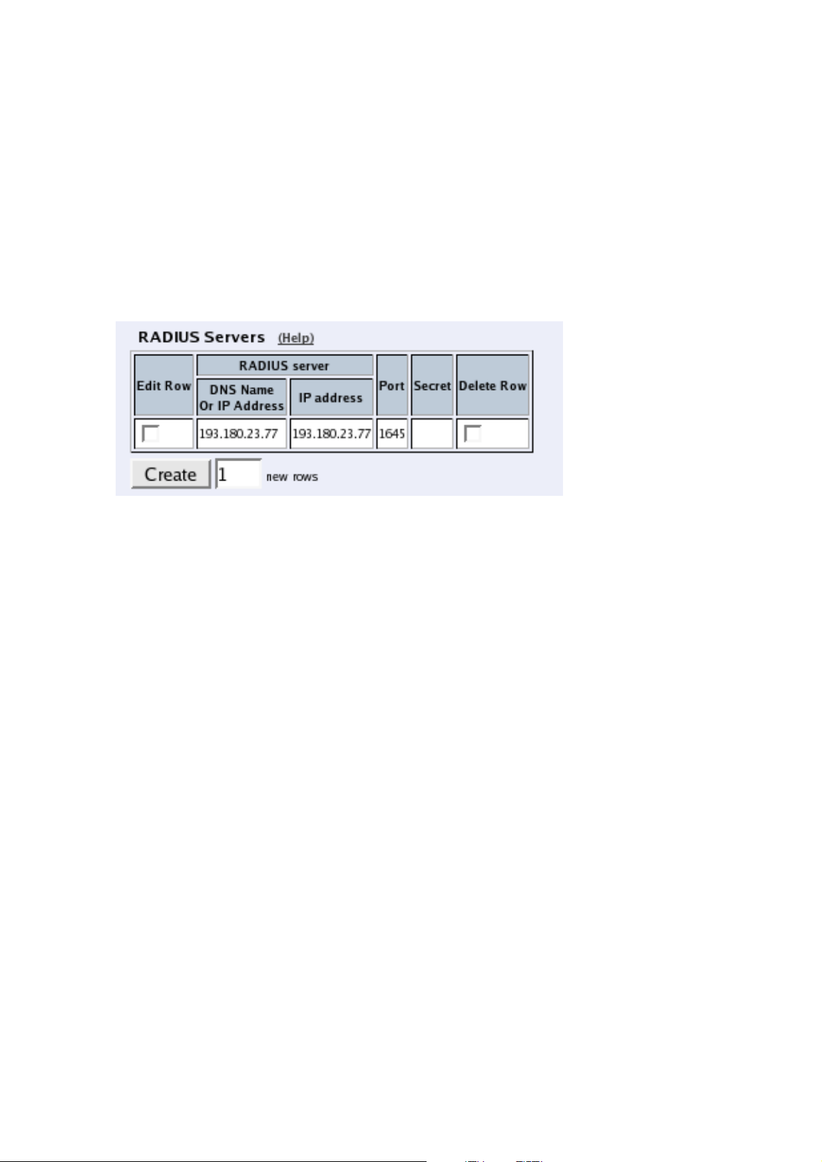
Chapter 6. Basic Configuration
is used for user authentication from VPN connections, you must do additional configuration
on the Authentication Server page.
The Telecommuting Module can also send accounting information about SIP calls to a RADIUS server.
RADIUS Servers
Enter the server(s) that the Telecommuting Module should use. When more than one RADIUS server is entered, make sure that their databases contain the same data, since the
Telecommuting Module regards them all alike and uses the server which first replies to a
request.
RADIUS server
Enter the DNS Name Or IP Address for the RADIUS server used for authentication.
In IP address, the IP address of the server is shown. It is updated whenever Look up all IP
addresses again is pressed, or the DNS Name Or IP Address field is changed.
Port
The official port for RADIUS is UDP port 1812. However, several RADIUS servers use port
1645, so you may have to change the port number either on the RADIUS server or in the
table.
Secret
A RADIUS authentication requires a ’shared secret’, which must be the same on both sides.
Since the secret is used as an encryption key, it is important that it is kept a secret. Since
the secret is saved unencrypted in the Telecommuting Module configuration, you should be
careful with where you store the configuration.
Delete Row
If you select this box, the row is deleted when you click on Create new rows, Save, or Look
up all IP addresses again.
Create
Enter the number of new rows you want to add to the table, and then click on Create.
83
Page 92

Chapter 6. Basic Configuration
Identifier
A RADIUS client may use either of two ways to identify itself for the RADIUS server: an IP
address or a name (identifier). You must use at least one of these ways, or the authentication
will fail.
Select here which method to use. The address or name in use must be registered at the
RADIUS servers specified in the top table, and must be unique in that RADIUS database.
Use NAS-IP-Address
If you select Yes, the Telecommuting Module’s IP address (the address selected under Con-
tact IP Address) will be enclosed as identity. If you select No, you must enter a NASIdentifier for the Telecommuting Module.
NAS-Identifier
You can enter a special identifier into this field. All characters except space are allowed according to the Telecommuting Module, but your RADIUS server may have some restrictions
on the identifier.
Contact IP Address
Select the IP address from which the Telecommuting Module should make connections to
RADIUS servers.
Contact RADIUS servers from
Select an IP address from which the Telecommuting Module should make connections to
the RADIUS server. A convenient choice of address is one on the interface closest to the
server. Select from the IP addresses configured for the Telecommuting Module interfaces
under Directly Connected Networks and Alias.
Status for RADIUS Servers
At the bottom of the page the status for the RADIUS servers is shown. Radiusmux is the part
of 3Com VCX IP Telecommuting Module that connects to the RADIUS servers.
If no authentication by RADIUS is configured, the radiusmux is not run. When you apply a
configuration which involves contacting a RADIUS server, the radiusmux is started.
84
Page 93

Chapter 6. Basic Configuration
RADIUS server
The IP address for this RADIUS server.
Score
Radiusmux gives points (the scale is 1 to 40, inclusive) to the different servers according
to their performance. The better server performance, the higher score. Radiusmux uses the
score to select which server to query primarily.
Sent requests
The number of UDP packets sent to this server.
Received replies
The number of UDP packets received from this server.
Consecutive sends
The number of consecutive UDP packets sent without response from the server.
Recent average response time
A calculated average of response time for packets for which response has been received.
Free slots
The RADIUS server allocates a certain number of slots for each RADIUS client, and every
pending request from the Telecommuting Module occupies a slot. Here you see the current
number of free slots.
Save
Saves the RADIUS configuration to the preliminary configuration.
Cancel
Reverts all of the above fields to their previous configuration.
Look up all IP addresses again
Looks up the IP addresses for all DNS names on this page in the DNS servers you entered
on the Basic Configuration page.
This button will only be visible if a DNS server has been configured.
85
Page 94

Chapter 6. Basic Configuration
Configuration of a RADIUS server
In this section it is assumed that you know how to configure your RADIUS server. Consult
your RADIUS manual for details.
Add the Telecommuting Module as a client in the RADIUS server. Make sure that the shared
secret here is the same as in the Telecommuting Module.
The Telecommuting Module checks the permissions for a user by looking at its RADIUS
attribute Service-Type.
If the Service-Type has the value Administrative (6), the user is allowed to configure the
Telecommuting Module.
If the value is Framed (2), the user is allowed to connect via VPN.
For the various privileges for users, there is an 3Com-specific RADIUS attribute defined
thus:
VENDOR 3Com 43
ATTRIBUTE 3Com-Admin-Account 1 integer 3Com
#
# Type of administrator account.
#
VALUE 3Com-Admin-Account Full-Access-Admin 1
VALUE 3Com-Admin-Account Backup-Admin 2
VALUE 3Com-Admin-Account Read-Only-Admin 3
VALUE 3Com-Admin-Account VPN-Admin 4
VALUE 3Com-Admin-Account SIP-Admin 5
VALUE 3Com-Admin-Account VPN-Reneg-Admin 6
To be able to authenticate SIP users, the RADIUS server must support Digest authentication.
You find a description of this in draft-sterman-aaa-sip-02 (Internet draft). This is all that is
required for it to work with 3Com VCX IP Telecommuting Module.
More information about RADIUS can be found in RFC 2865.
SNMP
SNMP is a network monitoring protocol, which enables a single server to monitor one or
more networks, including all network equipment like routers and firewalls. 3Com VCX IP
Telecommuting Module supports SNMP and can accordingly be monitored automatically.
The monitoring signaling consists of two main parts. The SNMP server sends requests to
the Telecommuting Module, which replies with a list of network parameters and their values
for the Telecommuting Module. The Telecommuting Module can also send messages (traps)
without the server prompting, when someone sends a request without valid authentication
and when the Telecommuting Module boots. You can also configure the Telecommuting
Module to send traps when certain threshold values are reached.
86
Page 95

Chapter 6. Basic Configuration
The 3Com VCX IP Telecommuting Module can only send parameters to the server; no
changes of configuration can be made through SNMP requests.
For more information about SNMP, read RFC 1157.
General
Here, select the IP addresses (local and remote) involved in the SNMP signaling. You can
also enter contact information for the Telecommuting Module.
The Telecommuting Module IP address to respond to SNMP requests
Select the IP address of the Telecommuting Module to which the SNMP servers should direct
their requests. Select from the addresses defined on the Interface pages under Network
Configuration.
Servers allowed to contact the Telecommuting Module via SNMP
Select the SNMP server(s) which are allowed to contact the Telecommuting Module. You
select from the network groups defined on the Networks and Computers page under Net-
work Configuration.
Contact person
Enter the name of the contact person for this 3Com VCX IP Telecommuting Module. This
information is sent with the parameter list as reply to an SNMP request from the server.
Node location
Enter the location of the Telecommuting Module. This information is sent with the parameter
list as reply to an SNMP request from the server.
SNMP v1 and v2c
In SNMP version 1 and 2c, the authentication is managed through an unencrypted password,
a community. Here, you select if the Telecommuting Module should accept access via v1 or
v2c, and enter the valid communities.
87
Page 96

Chapter 6. Basic Configuration
Access via SNMPv1 and SNMPv2c
Select if access via SNMP version 1 or 2c (using communities as the autentication method)
should be On or Off.
Community
Enter a password. Note that this password is stored unencrypted.
Delete Row
If you select this box, the row is deleted when you click on Create new rows, Save, or Look
up all IP addresses again.
Create
Enter the number of new rows you want to add to the table, and then click on Create.
SNMP v3
In SNMP version 3, the authentication is managed through the server sending a username
and an (in most cases) encrypted password to the Telecommuting Module, which verifies
the validity of them.
Here, you select if the Telecommuting Module should accept access via v3, and select the
authentication and encryption used for the SNMP reuqests.
Access via SNMPv3
Select if access via SNMP version 3 (using usernames and encrypted passwords as the autentication method) should be On or Off.
88
Page 97

Chapter 6. Basic Configuration
User
Enter a username which the server should use when contacting the Telecommuting Module.
Password
Press the Change password button to enter a password for this user.
Authentication
Select the authentication algorithm to use for SNMP requests. 3Com VCX IP Telecommuting Module supports the MD5 and SHA-1 algorithms.
Privacy
Select whether the SNMP request should be encrypted using AES or DES, or not be encrypted at all.
Delete Row
If you select this box, the row is deleted when you click on Create new rows, Save, or Look
up all IP addresses again.
Create
Enter the number of new rows you want to add to the table, and then click on Create.
SNMP Traps
If Trap sending function is On, the Telecommuting Module will send messages (traps) to
the server(s) entered below whenever an SNMP authentication fails or the Telecommuting
Module boots. They are also sent when the status is changed for an IPsec tunnel, and when
the Telecommuting Module discovers that a new software version is available.
You can also configure the unit to send traps when certain levels are reached (see Resource
Monitoring).
SNMP traps are sent from the IP address closest to the receiving SNMP server. If the
Telecommuting Module has been assigned more than one IP address on that network, the
address given in the Directly Connected Networks table will be used.
If the trap sending is disabled, no traps will be sent.
89
Page 98

Chapter 6. Basic Configuration
Trap sending function
Select if trap sending (at boot and failed SNMP authentication) should be On or Off.
Trap receiver
Enter the IP address, or a name in the DNS, of the server to which the Telecommuting
Module should send traps. If you enter a DNS name instead of an IP address, you must enter
the IP address of a DNS server on the Basic Configuration page.
IP address shows the IP address of the DNS Name Or IP Address you entered in the
previous field.
Community
Enter the password (community) which the Telecommuting Module should use when sending traps. The community is sent unencrypted over the network.
Version
Select the SNMP version to be used for traps. You can select v1 or v2c.
Delete Row
If you select this box, the row is deleted when you click on Create new rows, Save, or Look
up all IP addresses again.
Create
Enter the number of new rows you want to add to the table, and then click on Create.
Resource Monitoring
Your Telecommuting Module can send SNMP traps when usage passes certain levels. Set
the levels here. The trap receivers are configured in the SNMP Traps table.
For each usage, there is an Alarm by and a Resume by level. When the usage hits the Alarm
by level, the Telecommuting Module sends a trap about this and locks the trap sending for
that usage, which means that as long as the level stays high, no more traps are sent. When
the level goes down to below the Resume by level, the lock is released. Next time the Alarm
by level is reached, a new trap is sent.
To avoid excessive trap sending, it is recommended that the Alarm by and Resume by levels
for a resource are not set too close.
90
Page 99

Chapter 6. Basic Configuration
SIP Sessions Trap Levels
Enter the SIP sessions levels here. When the number of SIP sessions reaches the Alarm by
level, an SNMP trap is sent.
SIP User Registrations Trap Levels
Enter the SIP user registrations levels here. When the number of registered SIP users reaches
the Alarm by level, an SNMP trap is sent.
CPU Load Trap Levels
Enter the CPU load levels here. When CPU usage increases above the Alarm by limit, an
SNMP trap is sent.
Memory Usage Trap Levels
Enter the memory usage levels here. When memory usage increases above the Alarm by
limit, an SNMP trap is sent.
Download the 3Com MIB
This link leads to the 3Com-specific MIB (Management Information Base) definition for
your 3Com VCX IP Telecommuting Module.
The Telecommuting Module also supports these standard MIBs:
• mibII.system
• mibII.interfaces
• mibII.at
• mibII.ip
• mibII.icmp
• mibII.tcp
• mibII.udp
• mibII.snmp
91
Page 100

Chapter 6. Basic Configuration
Save
Saves the SNMP configuration to the preliminary configuration.
Cancel
Reverts all of the above fields to their previous configuration.
Look up all IP addresses again
Looks up the IP addresses for all DNS names on this page in the DNS servers you entered
on the Basic Configuration page.
This button will only be visible if a DNS server has been configured.
Dynamic DNS update
Usually, static DNS servers are used to associate a domain or host name with an IP address.
If the Telecommuting Module gets its public IP address via DHCP or PPPoE, the static DNS
servers will not work, as they do not automatically change bindings when the Telecommuting
Module get a new IP address.
3Com VCX IP Telecommuting Module supports dynamic DNS update at DynDNS.org. You
must purchase the update service at DynDNS.org before you can use it.
DynDNS General Configuration
Here, make settings which the Telecommuting Module will use when updating IP addresses
at DynDNS.org. In the descriptions below, the example domain example.com is used.
Use DynDNS
Select if the Telecommuting Module should use DynDNS services to update IP addresses.
DynDNS service
Select which service you use at DynDNS.
92
 Loading...