

Page 1

HPE 3100 v2 Switch Series
High Availability
Configuration Guide
Part number: 5998-5997s
Software version: Release 5213 and Release 5213P02
Document version: 6W101-20160506
Page 2

© Copyright 2016 Hewlett Packard Enterprise Development LP
The information contained herein is subject to change without notice. The only warranties for Hewlett Packard
Enterprise products and services are set forth in the express warranty statements acco mpanying such
products and services. Nothing herein should be construe d as constituting an additional warranty. Hewlett
Packard Enterprise shall not be liable for technical or editorial errors or omissions co ntained herein.
Confidential computer software. V alid license from Hewlett Packard Enterprise required for possession, use, or
copying. Consistent with FAR 12.211 and 12.212, Commercial Computer Software, Computer Software
Documentation, and T e chnical Data for Commercial Items are licensed to the U.S. Government under vendor’s
standard commercial license.
Links to third-party websites take you outside the Hewlett Packard Enterprise website. Hewlett Packard
Enterprise has no control over and is not responsible for information outside the Hewlett Packard Enterprise
website.
Acknowledgments
Intel®, Itanium®, Pentium®, Intel Inside®, and the Intel Inside logo are trademarks of Intel Corporation in the
United States and other countries.
Microsoft® and Windows® are trademarks of the Microsoft group of companies.
Adobe® and Acrobat® are trademarks of Adobe Systems In corporated.
Java and Oracle are registered trademarks of Oracle and/or its affiliates.
UNIX® is a registered trademark of The Open Group.
Page 3

Contents
High availability overview ················································································ 1
Availability requirements ···································································································································· 1
Availability evaluation ········································································································································· 1
High availability technologies ····························································································································· 2
Fault detection technologies ······················································································································ 2
Protection switchover technologies ············································································································ 2
Configuring Ethernet OAM ·············································································· 4
Ethernet OAM overview ····································································································································· 4
Major functions of Ethernet OAM ··············································································································· 4
Ethernet OAMPDUs ··································································································································· 4
How Ethernet OAM works ·························································································································· 5
Standards and protocols ···························································································································· 7
Ethernet OAM configuration task list ·················································································································· 7
Configuring basic Ethernet OAM functions ········································································································ 8
Configuring the Ethernet OAM connection detection timers ·············································································· 8
Configuring link monitoring ································································································································ 9
Configuring errored symbol event detection ······························································································ 9
Configuring errored frame event detection ································································································· 9
Configuring errored frame period event detection ······················································································ 9
Configuring errored frame seconds event detection ·················································································· 9
Configuring Ethernet OAM remote loopback ··································································································· 10
Enabling Ethernet OAM remote loopback ································································································ 10
Rejecting the Ethernet OAM remote loopback request from a remote port ············································· 11
Displaying and maintaining Ethernet OAM configuration ················································································· 11
Ethernet OAM configuration example ·············································································································· 12
Configuring CFD (available only on the HPE 3100 v2 EI) ····························· 15
Overview ·························································································································································· 15
Basic CFD concepts ································································································································· 15
CFD functions ·········································································································································· 17
Protocols and standards ·························································································································· 18
CFD configuration task list ······························································································································· 19
Configuring basic CFD settings ······················································································································· 19
Enabling CFD ··········································································································································· 20
Configuring the CFD protocol version ······································································································ 20
Configuring service instances ·················································································································· 20
Configuring MEPs ···································································································································· 21
Configuring MIP generation rules ············································································································· 21
Configuring CFD functions ······························································································································· 22
Configuration prerequisites ······················································································································ 22
Configuring CC on MEPs ························································································································· 22
Configuring LB on MEPs ·························································································································· 23
Configuring LT on MEPs ·························································································································· 23
Configuring AIS ········································································································································ 24
Configuring LM ········································································································································· 24
Configuring one-way DM ·························································································································· 24
Configuring two-way DM ·························································································································· 25
Configuring TST ······································································································································· 25
Displaying and maintaining CFD ······················································································································ 26
CFD configuration example ····························································································································· 27
Configuring DLDP ························································································· 33
DLDP overview ················································································································································ 33
Background ·············································································································································· 33
How DLDP works ····································································································································· 34
DLDP configuration task list ····························································································································· 40
i
Page 4

Configuring the duplex mode and speed of an Ethernet interface ··································································· 40
Enabling DLDP ················································································································································ 40
Setting DLDP mode ········································································································································· 41
Setting the interval to send advertisement packets ························································································· 41
Setting the delaydown timer ····························································································································· 42
Setting the port shutdown mode ······················································································································ 42
Configuring DLDP authentication ····················································································································· 43
Resetting DLDP state ······································································································································ 43
Displaying and maintaining DLDP ··················································································································· 44
DLDP configuration examples ························································································································· 44
Automatically shutting down unidirectional links ······················································································ 44
Manually shutting down unidirectional links ····························································································· 48
Troubleshooting DLDP ····································································································································· 51
Configuring RRPP ························································································· 52
RRPP overview ················································································································································ 52
Background ·············································································································································· 52
Basic concepts in RRPP ·························································································································· 52
RRPPDUS ················································································································································ 54
RRPP timers ············································································································································ 55
How RRPP works ····································································································································· 55
Typical RRPP networking ························································································································ 56
Protocols and standards ·························································································································· 59
RRPP configuration task list ···························································································································· 60
Creating an RRPP domain ······························································································································· 60
Configuring control VLANs ······························································································································· 61
Configuration guidelines ··························································································································· 61
Configuration procedure ··························································································································· 61
Configuring protected VLANs ·························································································································· 61
Configuring RRPP rings ··································································································································· 62
Configuring RRPP ports ··························································································································· 63
Configuring RRPP nodes ························································································································· 63
Activating an RRPP domain ····························································································································· 64
Configuring an RRPP ring group ····················································································································· 65
Configuration restrictions and guidelines ································································································· 65
Configuration procedure ··························································································································· 65
Displaying and maintaining RRPP ··················································································································· 66
RRPP configuration examples ························································································································· 66
Single ring configuration example ············································································································ 66
Intersecting ring configuration example ··································································································· 69
Dual homed rings configuration example ································································································· 74
Intersecting-ring load balancing configuration example ··········································································· 83
Troubleshooting ··············································································································································· 91
Configuring Smart Link (available only on the HPE 3100 v2 EI) ··················· 93
Smart Link overview ········································································································································· 93
Background ·············································································································································· 93
Terminology ············································································································································· 94
How Smart Link works ····························································································································· 94
Smart Link collaboration mechanisms ····································································································· 95
Smart Link configuration task list ····················································································································· 95
Configuring a Smart Link device ······················································································································ 96
Configuration prerequisites ······················································································································ 96
Configuring protected VLANs for a smart link group ················································································ 96
Configuring member ports for a smart link group ····················································································· 97
Configuring role preemption for a smart link group ·················································································· 98
Enabling the sending of flush messages ·································································································· 98
Configuring an associated device ···················································································································· 99
Configuration prerequisites ······················································································································ 99
Enabling the receiving of flush messages ································································································ 99
Displaying and maintaining Smart Link ············································································································ 99
Smart Link configuration examples ················································································································ 100
ii
Page 5

Single smart link group configuration example ······················································································ 100
Multiple smart link groups load sharing configuration example ······························································ 104
Configuring Monitor Link (available only on the HPE 3100 v2 EI) ·············· 109
Monitor Link overview ···································································································································· 109
Terminology ··········································································································································· 109
How Monitor Link works ························································································································· 110
Configuring Monitor Link ································································································································ 110
Configuration prerequisites ···················································································································· 110
Creating a monitor link group ················································································································· 110
Configuring monitor link group member ports ························································································ 110
Displaying and maintaining Monitor Link ······································································································· 111
Monitor Link configuration example ··············································································································· 111
Document conventions and icons ······························································· 115
Conventions ··················································································································································· 115
Network topology icons ·································································································································· 116
Support and other resources ······································································ 117
Accessing Hewlett Packard Enterprise Support ···························································································· 117
Accessing updates ········································································································································· 117
Websites ················································································································································ 118
Customer self repair ······························································································································· 118
Remote support ······································································································································ 118
Documentation feedback ······················································································································· 118
Index ··········································································································· 120
iii
Page 6

High availability overview
Communication interruptions can seriously affect widely-deployed value-added services such as
IPTV and video conference. Therefore, the basic network infrastructures must be able to provide
high availability.
The following are the effective ways to improve availability:
• Increasing fault tolerance
• Speeding up fault recovery
• Reducing impact of faults on services
Availability requirements
Availability requirements fall into three levels based on purpose and implementa tion.
Table 1 Availability requirements
Level Requirement Solution
• Hardware—Simplifying circuit design, enhancing
1
Decrease system software and
hardware faults
production techniques, and performing reliability
tests.
• Software—Reliability design and test
2
3
The level 1 availability requirement should be considered during the design and production process
of network devices. Level 2 should be considered during network design. Level 3 should be
considered during network deployment, according to the network infrastructure and service
characteristics.
Protect system functions from being
affected if faults occur
Enable the system to recover as fast
as possible
Availability evaluation
Mean Time Between Failures (MTBF) and Mean Time to Repair (MTTR) are used to evaluate the
availability of a network.
MTBF
MTBF is the predicted elapsed time between inherent failures of a system during operation. It is
typically in the unit of hours. A higher MTBF means a high availability.
MTTR
MTTR is the average time required to repair a failed system. MTTR in a broad sense also involves
spare parts management and customer services.
MTTR = fault detection time + hardware replacement time + system initialization time + link recovery
time + routing time + forwarding recovery time. A smaller value of each item means a smaller MTTR
and a higher availability.
Device and link redundancy and deployment of
switchover strategies
Performing fault detection, diagnosis, isolation, and
recovery technologies
1
Page 7

High availability technologies
Increasing MTBF or decreasing MTTR can enhance the availability of a network. The high
availability technologies described in this section meet the level 2 and level 3 high availability
requirements by decreasing MTTR.
High availability technologies can be classified as fault detection technologies or protection
switchover technologies.
Fault detection technologies
Fault detection technologies enable detection and diagnosis of network faults. CFD, DLDP, and
Ethernet OAM are data link layer fault detection technologies. NQA is used for diagnosis and
evaluation of network quality. Monitor Link works along with other high availability technologies to
detect faults through a collaboration mechanism.
Table 2 Fault detection technologies
Technology Introduction Reference
Connectivity Fault Detection (CFD), which conforms to IEEE
CFD (available only
on the HPE 3100
v2 EI)
802.1ag Connectivity Fault Management (CFM) and ITU-T
Y.1731, is an end-to-end per-VLAN link layer Operations,
Administration and Maintenance (OAM) mechanism used for
link connectivity detection, fault verification, and fault
location.
"Configuring CFD" in
High Availability
Configuration Guide
The Device link detection protocol (DLDP) deals with
unidirectional links that may occur in a network. Upon
DLDP
Ethernet OAM
NQA
Monitor Link
(available only on
the HPE 3100 v2
EI)
detecting a unidirectional link, DLDP, as configured, can
shut down the related port automatically or prompt users to
take actions to avoid network problems.
As a tool monitoring Layer 2 link status, Ethernet OAM is
mainly used to address common link-related issues on the
"last mile". You can monitor the status of the point-to-point
link between two directly connected devices by enabling
Ethernet OAM on them.
Network Quality Analyzer (NQA) analyzes network
performance, services and service quality through sending
test packets, and provides you with network performance
and service quality parameters such as jitter, TCP
connection delay, FTP connection delay and file transfer
rate.
Monitor Link works together with Layer 2 topology protocols
to adapt the up/down state of a downlink port to the state of
an uplink port. This feature enables fast link switchover on a
downstream device in response to the uplink state change
on its upstream device.
Protection switchover technologies
"Configuring DLDP"
in Hig
h Availability
Configuration Guide
"Configuring Ethernet
OAM" in High
ability
Avail
Configuration Guide
"Configuring NQA" in
Network
Management and
Monitoring
Configuration Guide
"Configuring Monitor
Link" in High
Availability
Configuration Guide
Protection switchover technologies aim at recovering network faults. They back up hardware, link,
routing, and service information for switchover in case of network faults, to ensure continuity of
network services.
2
Page 8

Table 3 Protection switchover technologies
Technology Introduction Reference
Ethernet Link
Aggregation
Ethernet link aggregation, most often simply called link
aggregation, aggregates multiple physical Ethernet links into
one logical link to increase link bandwidth beyond the l imits
of any one single link. This logical link is an aggregate link. It
allows for link redundancy because the member phys ical
links can dynamically back up one another.
"Configuring Ethernet
ink aggregation" in
—
Layer 2
Switching
Configuration Guide
LAN
Smart Link
(available only on
the HPE 3100 v2
EI)
MSTP
RRPP
Smart Link is a feature developed to address the slow
convergence issue with STP. It provides link redundancy as
well as fast convergence in a dual uplink network, allowing
the backup link to take over quickly when the primary link
fails.
As a Layer 2 management protocol, the Multiple Spanning
Tree Protocol (MSTP) eliminates Layer 2 loops by
selectively blocking redundant links in a network, and in the
mean time, allows for link redundancy.
The Rapid Ring Protection Protocol (RRPP) is a link layer
protocol designed for Ethernet rings. RRPP can prevent
broadcast storms caused by data loops when an Ethernet
ring is healthy, and rapidly restore the communication paths
between the nodes in the event that a link is disconnected on
the ring.
"Configuring Smart
Link" in High
Availability
Configuration Guide
"Configuring
spanning tree" in
Layer 2—LAN
Switching
Configuration Guide
"Configuring RRPP"
h Availability
in Hig
Configuration Guide
A single availability technology cannot solve all problems. Therefore, a combination of availability
technologies, chosen on the basis of detailed analysis of network environments and user
requirements, should be used to enhance network availability. For example, access-layer devices
should be connected to distribution-layer devices over redundant links, and core-layer devices
should be fully meshed. Also, network availability should be considered during planning prior to
building a network.
3
Page 9
Configuring Ethernet OAM
Ethernet OAM overview
Ethernet Operation, Administration and Maintenance (OAM) is a tool that monitors Layer 2 link
status and addresses common link-related issues on the "last mile." You can use it to monitor the
status of the point-to-point link between two directly connected devices.
Major functions of Ethernet OAM
Ethernet OAM provides the following functions:
• Link performance monitoring—Monitors the performance indices of a link, including packet
loss, delay, and jitter, and collects traffic statistics of various types
• Fault detection and alarm—Checks the connectivity of a link by sending OAM protocol data
units (OAMPDUs) and reports to the network administrators when a link error occurs
• Remote loopback—Checks link quality and locates link errors by looping back OAMPDUs
Ethernet OAMPDUs
Ethernet OAM works on the data link layer. Ethernet OAM reports the link status by periodically
exchanging OAMPDUs between devices so that the administrator can effectively manage the
network.
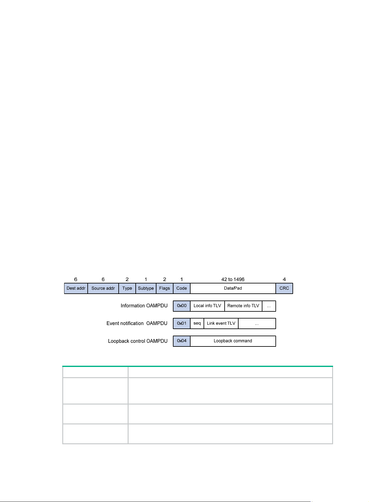
Ethernet OAMPDUs fall into the following types: Information, Event Notification, and Loopback
Control.
Figure 1 Formats of different types of Ethernet OAMPDUs
Table 4 Fields in an OAMPDU
Field Description
Destination MAC address of the Ethernet OAMPDU
Dest addr
It is a slow protocol multicast address, 0180c2000002. Bridges cannot forward
slow protocol packets, so Ethernet OAMPDUs cannot be forwarded.
Source addr
Type
Source MAC address of the Ethernet OAMPDU
It is the bridge MAC address of the sending side and is a unicast MAC address.
Type of the encapsulated protocol in the Ethernet OAMPDU
The value is 0x8809.
4
Page 10

Field Description
Subtype
Flags Status information of an Ethernet OAM entity
Code Type of the Ethernet OAMPDU
NOTE:
The specific protocol being encapsulated in the Ethernet OAMPDU
The value is 0x03.
Throughout this document, a port with Ethernet OAM enabled is an Ethernet OAM entity or an OAM
entity.
Table 5 Functions of different types of OAMPDUs
OAMPDU type Function
Used for transmitting state information of an Ethernet OAM entity—including the
Information OAMPDU
information about the local device and remote devices and customized
information—to the remote Ethernet OAM entity and maintaining OAM
connections.
Event Notification
OAMPDU
Loopback Control
OAMPDU
Used by link monitoring to notify the remote OAM entity when it detects problems
on the link in between.
Used for remote loopback control. By inserting the information used to
enable/disable loopback to a loopback control OAMPDU, you can enable/disable
loopback on a remote OAM entity.
How Ethernet OAM works
This section describes the working procedures of Ethernet OAM.
Ethernet OAM connection establishment
Ethernet OAM connection is the basis of all the other Ethernet OAM functions. OAM connection
establishment is also known as the "Discovery phase", where an Ethernet OAM entity discovers
remote OAM entities and establishes sessions with them.
In this phase, interconnected OAM entities determine whether Ethernet OAM connections can be
established, by exchanging Information OAMPDUs to notify the peer of their OAM configuration
information and the OAM capabilities of the local nodes. An Ethernet OAM connection can be
established between entities that have matching Loopback, link detecting, and link event settings.
After an Ethernet OAM connection is established, Ethernet OAM takes effect on both sides.
For Ethernet OAM connection establishment, a device can operate in active Ethernet OAM mode or
passive Ethernet OAM mode, but a switch role will be somewhat different depending on the mode.
Table 6 Active Ethernet OAM mode and passive Ethernet OAM mode
Item Active Ethernet OAM mode
Initiating OAM Discovery Available Unavailable
Responding to OAM Discovery Available Available
Transmitting Information
OAMPDUs
Transmitting Event Notification
OAMPDUs
Available Available
Available Available
5
Passive Ethernet OAM
mode
Page 11

Item Active Ethernet OAM mode
Transmitting Information
OAMPDUs without any TLV
Transmitting Loopback Control
OAMPDUs
Responding to Loopback Control
OAMPDUs
NOTE:
• Only OAM entities operating in active OAM mode can initiate OAM connections. OAM entities
operating in passive mode wait and respond to the connection requests sent by their peers.
• No OAM connection can be established between OAM entities operating in passive OAM mode.
After an Ethernet OAM connection is established, the Ethernet OAM entities on both sides ex change
Information OAMPDUs at the handshake packet transmission interval to check whether the Ethernet
OAM connection is normal. If an Ethernet OAM entity receives no Information OAMPDU within the
Ethernet OAM connection timeout time, the Ethernet OAM connection is considered disconnected.
Link monitoring
Error detection in an Ethernet is difficult, especially when the physical connection in the network is
not disconnected but network performance is degrading gradually. Link monitoring is used to detect
and indicate link faults in various environments. Ethernet OAM implements link monitoring through
the exchange of Event Notification OAMPDUs. When detecting one of the link error events listed
in Table 7, the local OAM entity sends
entity. With the log information, network administrators can keep track of network status promptly.
Passive Ethernet OAM
mode
Available Available
Available Unavailable
Available—if both sides operate
in active OAM mode
Available
an Event Notification OAMPDU to notify the remote OAM
Table 7 Ethernet OAM link error events
Ethernet OAM link events Description
Errored symbol event
Errored frame event
Errored frame period event
Errored frame seconds event
The system transforms the period of detecting errored frame period events into the maximum
number of 64-byte frames (excluding the interframe spacing and preamble) that a port can send in
the specified period. The system takes the maximum number of frames sent as the period. The
maximum number of frames sent is calculated using this formula: the maximum number of frames =
interface bandwidth (bps) × errored frame period event detection period (in ms)/(64 × 8 × 1000).
A second in which errored frames appear is called an "errored frame second."
Remote fault detection
An errored symbol event occurs when the number of detected
symbol errors during a specified detection interval exceeds the
predefined threshold.
An errored frame event occurs when the number of detected error
frames during a specified interval exceeds the predefined
threshold.
An errored frame period event occurs if the number of frame errors
in a specific number of received frames exceeds the predefined
threshold.
An errored frame seconds event occurs when the number of error
frame seconds detected on a port during a specified detection
interval reaches the error threshold.
Information OAMPDUs are exchanged periodically among Ethernet OAM entities across established
OAM connections. In a network where traffic is interrupted due to device failures or unavailability, the
flag field defined in information OAMPDUs allows an Ethernet OAM entity to send error
6
Page 12

information—the critical link event type—to its peer . You can use the log information to track ongoing
link status and troubleshoot problems promptly.
Table 8 Critical link events
Type Description
Link Fault Peer link signal is lost. Once per second
Dying Gasp
Critical Event An undetermined critical event occurred. Non-stop
This Switch Series is able to receive information OAMPDUs carrying the critical link events listed
in Table 8.
Only the Giga
This Switch Series is able to send information OAMPDUs carrying Dying Gasp events when the
device is rebooted or relevant ports are manually shut down.
This Switch Series is unable to send information OAMPDUs carrying Critical Events.
Remote loopback
Remote loopback is available only after the Ethernet OAM connection is established. With remote
loopback enabled, the Ethernet OAM entity operating in active Ethernet OAM mode sends
non-OAMPDUs to its peer. After receiving these frames, the peer does not forward them according
to their destination addresses. Instead, it returns them to the sender along the original path.
Remote loopback enables you to check the link status and locate link failures. Performing remote
loopback periodically helps to detect network faults promptly. Furthermore, performing remote
loopback by network segments helps to locate network faults.
OAMPDU transmission
frequencies
A power failure or other unexpected error
occurred.
Non-stop
bit fiber ports are able to send information OAMPDUs carrying Link Fault events.
Standards and protocols
Ethernet OAM is defined in IEEE 802.3ah (Carrier Sense Multiple Access with Collision Detection
(CSMA/CD) Access Method and Physical Layer Specifications.
Ethernet OAM configuration task list
Task Remarks
Configuring basic Ethernet OAM functions Required
Configuring the Ethernet OAM connection detection timers Optional
Configuring errored symbol event detection Optional
Configuring link
monitoring
Configuring
Ethernet OAM
remote loopback
Configuring errored frame event detection Optional
Configuring errored frame period event detection Optional
Configuring errored frame seconds event
detection
Enabling Ethernet OAM remote loopback Optional
Rejecting the Ethernet OAM remote loopback
request from a remote port
Optional
Optional
7
Page 13

Configuring basic Ethernet OAM functions
For Ethernet OAM connection establishment, an Ethernet OAM entity operates in active mode or
passive mode. Only an Ethernet OAM entity in active mode can initiate connection establishment.
After Ethernet OAM is enabled on an Ethernet port, according to its Ethernet OAM mode, the
Ethernet port establishes an Ethernet OAM connection with its peer port.
To change the Ethernet OAM mode on an Ethernet OAM-enabled port, you must first disable
Ethernet OAM on the port.
To configure basic Ethernet OAM functions:
Step Command Remarks
1. Enter system view.
2. Enter Layer 2 Ethernet
interface view.
3. Set the Ethernet OAM mode.
4. Enable Ethernet OAM on the
current port.
system-view
interface
interface-number
oam mode
oam enable
interface-type
active
{
passive
|
N/A
N/A
Optional.
}
The default is active Ethernet
OAM mode.
Ethernet OAM is disabled by
default.
Configuring the Ethernet OAM connection detection timers
After an Ethernet OAM connection is established, the Ethernet OAM entities on both sides ex change
Information OAMPDUs at the handshake packet transmission interval to check whether the Ethernet
OAM connection is normal. If an Ethernet OAM entity receives no Information OAMPDU within the
Ethernet OAM connection timeout time, the Ethernet OAM connection is considered disconnected.
By adjusting the handshake packet transmission interval and the connection timeout timer, you can
change the detection time resolution for Ethernet OAM connections.
After the timeout timer of an Ethernet OAM connection expires, the local OAM entity ages out its
connection with the peer OAM entity, causing the OAM connection to be disconnected. Hewlett
Packard Enterprise recommends that you set the connection timeout timer to at least five times the
handshake packet transmission interval, ensuring the stability of Ethernet OAM conne ction s.
To configure the Ethernet OAM connection detection timers:
Step Command Remarks
1. Enter system view.
2. Configure the Ethernet OAM
handshake packet
transmission interval.
3. Configure the Ethernet OAM
connection timeout timer.
system-view
oam timer hello
oam timer keepalive
interval
interval
N/A
Optional.
1000 millisecond by default.
Optional.
5000 milliseconds by default.
8
Page 14

Configuring link monitoring
After Ethernet OAM connections are established, the link monitoring periods and thresholds
configured in this section take effect on all Ethernet ports automatically.
Configuring errored symbol event detection
Step Command Remarks
4. Enter system view.
5. Configure the errored
symbol event
detection interval.
6. Configure the errored
symbol event
triggering threshold.
Configuring errored frame event detection
system-view
oam errored-symbol period
period-value
oam errored-symbol threshold
threshold-value
N/A
Optional.
1 second by default.
Optional.
1 by default.
Step Command Remarks
1. Enter system view.
2. Configure the errored frame
event detection interval.
3. Configure the errored frame
event triggering threshold.
system-view
oam errored-frame period
period-value
oam errored-frame threshold
threshold-value
N/A
Optional.
1 second by default.
Optional.
1 by default.
Configuring errored frame period event detection
Step Command Remarks
1. Enter system view.
2. Configure the errored
frame period event
detection period.
3. Configure the errored
frame period event
triggering threshold.
system-view
oam errored-frame-period period
period-value
oam errored-frame-period threshold
threshold-value
N/A
Optional.
1000 milliseconds by default.
Optional.
1 by default.
Configuring errored frame seconds event detection
IMPORTANT:
Make sure the errored frame seconds triggering thre shold is less than the errored frame seconds
detection interval. Otherwise, no errored frame seconds event can be generated.
9
Page 15

To configure errored frame seconds event detection:
Step Command Remarks
1. Enter system view.
2. Configure the errored frame
seconds event detection
interval.
3. Configure the errored frame
seconds event triggering
threshold.
system-view
oam errored-frame-seconds
period
oam errored-frame-seconds
threshold
period-value
threshold-value
N/A
Optional.
60 second by default.
Optional.
1 by default.
Configuring Ethernet OAM remote loopback
Enabling Ethernet OAM remote loopback
CAUTION:
Use this function with caution, because enabling Ethernet OAM remote loopback impacts other
services.
When you enable Ethernet OAM remote loopback on a port, the port sends Loopback Control
OAMPDUs to a remote port, and the remote port enters the loopback state. The port then sends test
frames to the remote port. By observing how many of these test frames return, you can calculate the
packet loss ratio on the link to evaluate the link performance.
Y ou can enable Ethernet OAM remote l oopback on a specific port in user view , system view , or Layer
2 Ethernet interface view. The configuration effects are the same.
Configuration guidelines
• Ethernet OAM remote loopback is available only after the Ethernet OAM connection is
established and can be performed only by Ethernet OAM entities operating in active Ethernet
OAM mode.
• Remote loopback is available only on full-duplex links that support remote loopback at both
ends.
• Ethernet OAM remote loopback must be supported by both the remote port and the sending
port.
• Enabling Ethernet OAM remote loopback interrupts data communications. After Ethernet OAM
remote loopback is disabled, all the ports involved will shut down and then come up. Ethernet
OAM remote loopback can be disabled by any of the following actions: executing the undo
oam enable command to disable Ethernet OAM; executing the undo oam loopback interface
or undo oam loopback command to disable Ethernet OAM remote loopback; and Ethernet
OAM connection timing out.
• Ethernet OAM remote loopback is only applicable to individual links. It is not applicable to link
aggregation member ports. In addition, do not assign ports where Ethernet OAM remote
loopback is being performed to link aggregation groups. For more information a bout link
aggregation groups, see Layer 2—LAN Switching Configuration Guide.
• Enabling internal loopback test on a port in remote loopback test can terminate the remote
loopback test. For more information about loopback test, see Layer 2—LAN Switching
Configuration Guide
.
Configuration procedure
To enable Ethernet OAM remote loopback in user view:
10
Page 16

Task Command Remarks
Enable Ethernet OAM remote
loopback on a specific port.
To enable Ethernet OAM remote loopback in system view:
oam loopback interface
interface-type interface-number
Disabled by default.
Step Command Remarks
1. Enter system view.
2. Enable Ethernet OAM
remote loopback on a
specific port.
To enable Ethernet OAM remote loopback in Layer 2 Ethernet interface view:
system-view
oam loopback interface
interface-type interface-number
N/A
Disabled by default.
Step Command Remarks
1. Enter system view.
2. Enter Layer 2 Ethernet
interface view.
3. Enable Ethernet OAM
remote loopback on the port.
system-view
interface
interface-number
oam loopback
interface-type
N/A
N/A
Disabled by default.
Rejecting the Ethernet OAM remote loopback request from a remote port
The Ethernet OAM remote loopback function impacts other services. To solve this problem, you can
disable a port from being controlled by the Loopback Control OAMPDUs sent by a remote port. The
local port then rejects the Ethernet OAM remote loopback request from the remote port.
To reject the Ethernet OAM remote loopback request from a remote port:
Step Command Remarks
1. Enter system view.
2. Enter Layer 2 Ethernet
interface view.
3. Reject the Ethernet OAM
remote loopback request
from a remote port.
system-view
interface
interface-number
oam loopback reject-request
interface-type
N/A
N/A
By default, a port does not reject
the Ethernet OAM remote
loopback request from a remote
port.
Displaying and maintaining Ethernet OAM configuration
Task Command Remarks
Display global Ethernet OAM
configuration.
display oam configuration
begin
{
regular-expression ]
exclude
|
11
include
|
}
[ |
Available in any view
Page 17
Task Command Remarks
display oam critical-event
interface
Display the statistics on critical
events after an Ethernet OAM
connection is established.
[
interface-number ] [ | {
exclude
regular-expression ]
interface-type
include
|
}
begin
|
Available in any view
Display the statistics on Ethernet
OAM link error events after an
Ethernet OAM connection is
established.
Display the information about an
Ethernet OAM connection.
Clear statistics on Ethernet OAM
packets and Ethernet OAM link
error events.
display oam link-event { local
remote
interface-type interface-number ]
[ | {
regular-expression ]
display oam { local
interface
[
interface-number ] [ | {
exclude
regular-expression ]
reset oam [ interface
interface-type interface-number ]
} [
begin
|
interface
exclude
|
interface-type
include
|
|
}
include
remote }
begin
|
Available in any view
}
|
Available in any view
Available in user view
Ethernet OAM configuration example
Network requirements
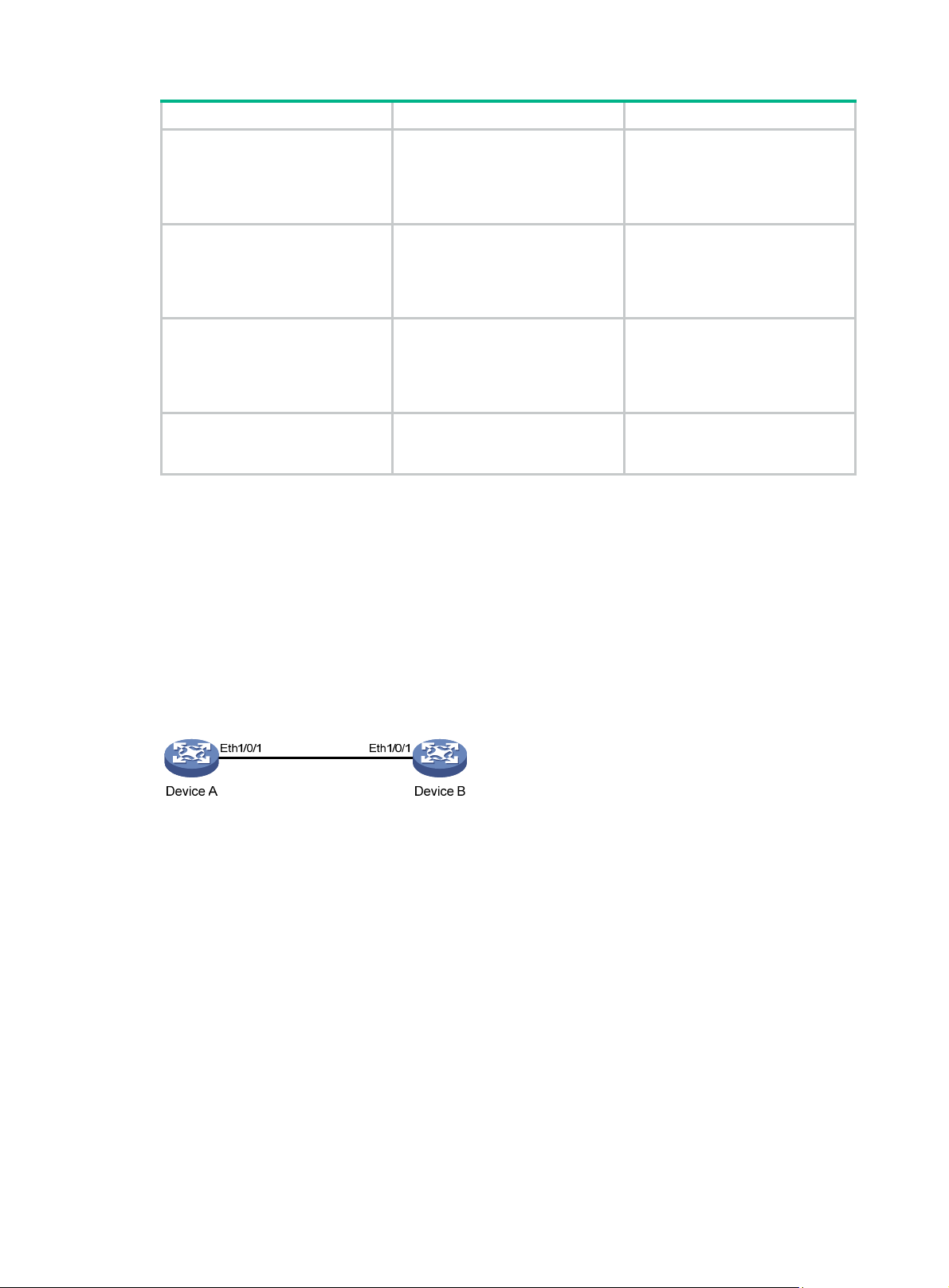
On the network shown in Figure 2, perform the following operations:
• Enable Ethernet OAM on Device A and Device B to auto-detect link errors between the two
devices
• Monitor the performance of the link between Device A and Device B by collecting statistics
about the error frames received by Device A
Figure 2 Network diagram
Configuration procedure
1. Configure Device A:
# Configure Ethernet 1/0/1 to operate in passive Ethernet OAM mode and enable Ethernet
OAM for it.
<DeviceA> system-view
[DeviceA] interface ethernet 1/0/1
[DeviceA-Ethernet1/0/1] oam mode passive
[DeviceA-Ethernet1/0/1] oam enable
[DeviceA-Ethernet1/0/1] quit
# Set the errored frame detection interval to 20 seconds and set the errored frame event
triggering threshold to 10.
[DeviceA] oam errored-frame period 20
[DeviceA] oam errored-frame threshold 10
2. Configure Device B:
12
Page 18

# Configure Ethernet 1/0/1 to operate in active Ethernet OAM mode (the default) and enable
Ethernet OAM for it.
<DeviceB> system-view
[DeviceB] interface ethernet 1/0/1
[DeviceA-Ethernet1/0/1] oam mode active
[DeviceB-Ethernet1/0/1] oam enable
[DeviceB-Ethernet1/0/1] quit
3. Verify the configuration:
Use the display oam configuration command to display the Ethernet OAM configuration. For
example:
# Display the Ethernet OAM configuration on Device A.
[DeviceA] display oam configuration
Configuration of the link event window/threshold :
-------------------------------------------------------------------------Errored-symbol Event period(in seconds) : 1
Errored-symbol Event threshold : 1
Errored-frame Event period(in seconds) : 20
Errored-frame Event threshold : 10
Errored-frame-period Event period(in ms) : 1000
Errored-frame-period Event threshold : 1
Errored-frame-seconds Event period(in seconds) : 60
Errored-frame-seconds Event threshold : 1
Configuration of the timer :
-------------------------------------------------------------------------Hello timer(in ms) : 1000
Keepalive timer(in ms) : 5000
The output shows that the detection period of errored frame events is 20 seconds, the detection
threshold is 10 seconds, and all the other parameters use the default values.
You can use the display oam critical-event command to display the statistics of Ethernet
OAM critical link events. For example:
# Display the statistics of Ethernet OAM critical link events on all the ports of Device A.
[DeviceA] display oam critical-event
Port : Ethernet1/0/1
Link Status : Up
Event statistic :
------------------------------------------------------------------------Link Fault :0 Dying Gasp : 0 Critical Event : 0
The output shows that no critical link event occurred on the link between Device A and Device
B.
You can use the display oam link-event command to display the statistics of Ethernet OAM
link error events. For example:
# Display Ethernet OAM link event statistics of the remote end of Device B.
[DeviceB] display oam link-event remote
Port :Ethernet1/0/1
Link Status :Up
OAMRemoteErrFrameEvent : (ms = milliseconds)
--------------------------------------------------------------------Event Time Stamp : 5789 Errored FrameWindow : 200(100ms)
13
Page 19

Errored Frame Threshold : 10 Errored Frame : 13
Error Running Total : 350 Event Running Total : 17
The output shows that 350 errors occurred since Ethernet OAM was enabled on Device A, 17 of
which are caused by error frames. The link is unstable.
14
Page 20
Configuring CFD (available only on the HPE 3100 v2 EI)
Overview
Connectivity Fault Detection (CFD) is an end-to-end per-VLAN link layer OAM mechanism used for
link connectivity detection, fault verification, and fault location. It conforms to IEEE 802.1ag CFM and
ITU-T Y.1731.
Basic CFD concepts
This section explains the concepts of CFD.
MD
A maintenance domain (M D) defines the network or part of the network where CFD plays its role. An
MD is identified by its MD name.
To accurately locate faults, CFD assigns eight levels ranging from 0 to 7 to MDs. The bigger the
number, the higher the leve l, and the larger the area covered. If the outer domain has a higher level
than the nested one, domains can touch or nest, but they cannot intersect or overlap.
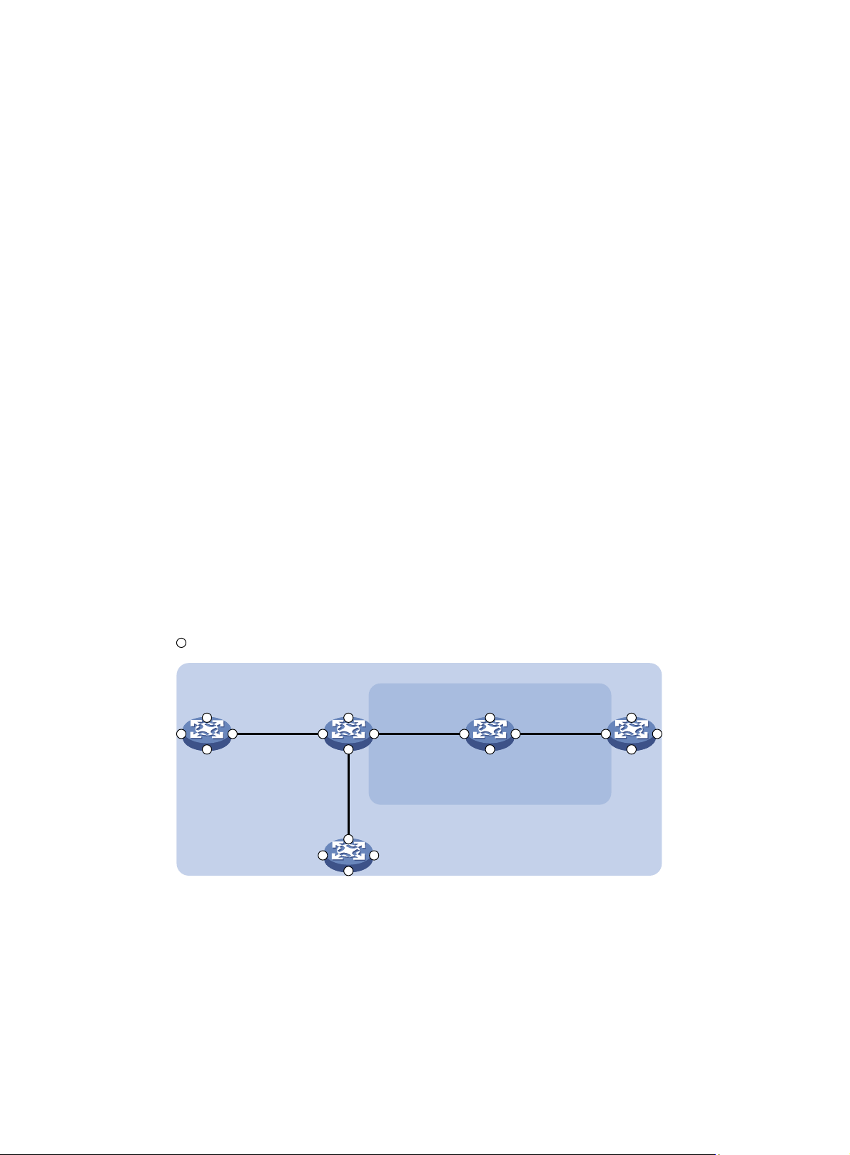
MD levels facilitate fault location and its accuracy. As shown in Figure 3, MD_A
in light blue nests
MD_B in dark blue. If a connectivity fault is detected at the boundary of MD_A, any of the devices in
MD_A, including Device A through Device E, may fail. If a connectivity fault is also detected at the
boundary of MD_B, the failure points may be any of Device B through Device D. If the devices in
MD_B can operate properly, at least Device C is operational.
Figure 3 Two nested MDs
Port
Port2
Port1 Port3
Device A Device B Device C Device D
Port4 Port4 Port4 Port4
Port1 Port3
Port1 Port3
Device E
Port2
Port2
Port4
Port2
Port1 Port3
Port2
Port1 Port3
MD_B
MD_A
VLAN 100
CFD exchanges messages and performs operations on a per-domain basis. By planning MDs
properly in a network, you can use CFD to rapidly locate failure points.
MA
A maintenance association (MA) is a part of an MD. You can configure multiple MAs in an MD as
needed. An MA is identified by the "MD name + MA name".
15
Page 21
MP
An MA serves a VLAN. Packets sent by the MPs in an MA carry the relevant VLAN tag. An MP can
receive packets sent by other MPs in the same MA. The level of an MA equals the level of the MD
that the MA belongs to.
An MP is configured on a port and belongs to an MA. MPs include maintenance association end
points (MEPs) and maintenance association intermediate points (MIPs).
• MEPs
MEPs define the boundary of the MA. Each MEP is identified by a MEP ID.
The MA to which a MEP belongs defines the VLAN of packets sent by the MEP. The level of a
MEP is equal to the level of the MD to which the MEP belongs, and the level of packets sent by
a MEP equals the level of the MEP. The level of a MEP determines the levels of packets that the
MEP can process. A MEP forwards packets at a higher level and processes packets of its own
level or lower. The processing procedure is specific to packets in the same VLAN. Packets of
different VLANs are independent.
MEPs are either inward-facing or outward-facing. An outward-facing MEP sends packets to its
host port. An inward-facing MEP does not send packet s to its host port. Rather, it sends packets
to other ports on the device.
• MIP
A MIP is internal to an MA. It cannot send CFD packets actively. However, a MIP can handle
and respond to CFD packets. By cooperating with MEPs, a MIP can perform a function similar
to ping and traceroute. A MIP forwards packets of a different level without any processing and
only processes packet of its own level.
The MA to which a MIP belongs defines the VLAN of packets that the MEP can receive. The
level of a MIP is defined by its generation rule and the MD that the MIP belongs to. MIPs are
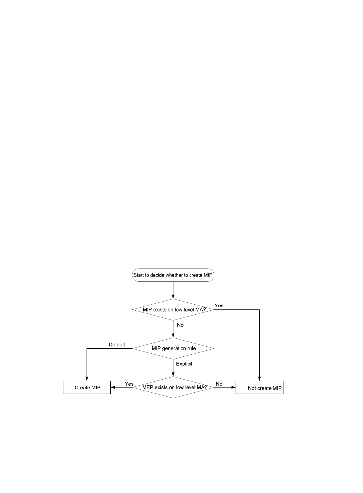
generated on each port automatically according to related MIP generation rules. If a port has no
MIP, the system will examine the MAs in each MD (from low to high levels), and follow the
procedure as described in Figure 4 to determin
e whether to create MIPs at the relevant level.
Figure 4 Procedure of creating MIPs
Figure 5 demonstrates a grading example of the CFD module. Four levels of MDs (0, 2, 3, and 5) are
designed. The bigger the number, the higher the level, and the larger the area covered. MPs are
configured on the ports of device A through device F. Port 1 of device B is configured with the
following MPs—a level 5 MIP, a level 3 inward-facing MEP, a level 2 inward-facing MEP, and a level
0 outward-facing MEP.
16
Page 22
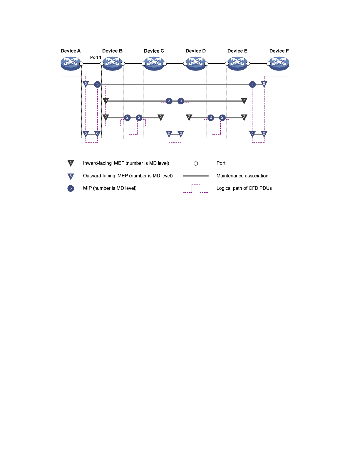
Figure 5 CFD grading example
MEP list
A MEP list is a collection of configurable local MEPs and the remote MEPs to be monitored in the
same MA. It lists all MEPs configured on different devices in the same MA. The MEPs all have
unique MEP IDs. When a MEP receives from a remote device a continuity check message (CCM)
with a MEP ID not included in the MEP list of the MA, it drops the message.
CFD functions
CFD works effectively only in properly configured networks. Its functions, which are implemented
through the MPs, include:
• Continuity check (CC)
• Loopback (LB)
• Linktrace (LT)
• Alarm indication signal (AIS)
• Loss measurement (LM)
• Delay measurement (DM)
• Test (TST)
CC
Connectivity faults are usua lly caused by device faults or configuration errors. CC examines the
connectivity between MEPs. This function is implemented through periodic sending of continuity
check messages (CCMs) by the MEPs. A CCM sent by one MEP is intended to be received by all of
the other MEPs in the same MA. If a MEP fails to receive the CCMs within 3.5 times the sending
interval, the link is considered faulty and a log is generated. When multiple MEPs send CCMs at the
same time, the multipoint-to-multipoint link check is achieved. CCM frames are multicast frames.
LB
Similar to ping at the IP layer, LB verifies the connectivity between a source device and a target
device. To implement this function, the source MEP sends loopback messages (LBMs) to the target
MEP. Depending on whether the source MEP can receive a loopback reply message (LBR) from the
17
Page 23

LT
AIS
LM
target MEP, the link state between the two can be verified. LBM frames and LBR frames are unicast
frames.
LT is similar to traceroute. It identifies the path between the source MEP and the target MP. This
function is implemented in the following way—the source MEP sends the linktrace messages (LTMs)
to the target MP. After receiving the messages, the target MP and the MIPs that the L TM frames pass
send back linktrace reply messages (LTRs) to the source MEP. Based on the reply messages, the
source MEP can identify the path to the target MP. LTM frames are multicast frames and LTRs are
unicast frames.
The AIS function suppresses the numbe r of error ala rms reported by MEPs. If a local MEP receives
no CCM frames from its peer MEP within 3.5 times the CCM transmission interval, it immediately
starts to send AIS frames periodically in the opposite direction of CCM frames. Upon receiving the
AIS frames, the peer MEP suppresses the error alarms locally , and continues to send the AIS frames.
If the local MEP receives CCM frames within 3.5 times the CCM transmission interval, it stops
sending AIS frames and restores the error alarm function. AIS frames are multicast frames.
The LM function measures the frame loss in a certain direction between a pair of MEPs. The source
MEP sends loss measurement messages (LMMs) to the target MEP, the target MEP responds with
loss measurement replies (LMRs), and the source MEP calculates the number of lost frames
according to the counter values of the two consecutive LMRs (the current LMR and the previous
LMR). LMMs and LMRs are multicast frames.
DM
TST
The DM function measures frame delays between two MEPs, including one-way and two-way frame
delays.
1. One-way frame delay measurement
The source MEP sends a one-way delay measurement (1DM) frame, which carries the
transmission time, to the target MEP. Upon receiving the 1DM frame, the target MEP records
the reception time, and calculates and records the link transmission delay and jitter (delay
variation) according to the transmission time and reception time. 1DM frames are multicast
frames.
2. Two-way frame delay measurement
The source MEP sends a delay measurement message (DMM), which carries the transmi ssion
time, to the target MEP. Upon receiving the DMM, the target MEP responds with a delay
measurement reply (DMR), which carries the reception time and transmission time of the DMM
and the transmission time of the DMR. Upon receiving the DMR, the source MEP reco rds the
DMR reception time, and calculates the link transmission delay and jitter according to the DMR
reception time and DMM transmission time. DMM frames and DMR frames are multicast
frames.
The TST function tests the bit errors between two MEPs. The source MEP sends a TST frame, whi ch
carries the test pattern, such as pseudo random bit sequence (PRBS) or all-zero, to the target MEP.
Upon receiving the TST frame, the target MEP determines the bit errors by calculating and
comparing the content of the TST frame. TST frames are unicast frames.
Protocols and standards
• IEEE 802.1ag, Virtual Bridged Local Area Networks Amendment 5: Connectivity Fault
Management
• ITU-T Y.1731, OAM functions and mechanisms for Ethernet based networks
18
Page 24

CFD configuration task list
For CFD to operate properly, design the network by performing the following tasks:
• Grade the MDs in the entire network and define the boundary of each MD.
• Assign a name for each MD. Make sure the same MD has the same name on different devices.
• Define the MA in each MD according to the VLAN you want to monitor.
• Assign a name for each MA. Make sure the same MA in the same MD has the same name on
different devices.
• Determine the MEP list of each MA in each MD. Make sure devices in the same MA maintain
the same MEP list.
• At the edges of MD and MA, MEPs should be designed at the device port. MIPs can be
designed on devices or ports that are not at the edges.
Tasks Remarks
Enabling CFD Req
Configuring the CFD protocol version Optional.
Creating a service instance
ith the MD name
Configuring basic CFD settings
Configuring
service instances
w
Creating a service instance
without the MD name
uired.
Required.
Perform either task.
Configuring MEPs Required.
Configuring MIP generation rules Required.
uired.
Configuring CFD
functions
Configuring CC on MEPs Req
Configuring LB on MEPs Optional.
Configuring LT on MEPs Optional.
Configuring AIS Optional.
Configuring LM Optional.
Configuring one-way DM Optional.
Configuring two-way DM Optional.
Configuring TST Optional.
Typically, a port blocked by the spanning tree feature cannot receive or send CFD messages except
in the following cases:
• The port is configured as an outward-facing MEP.
• The port is configured as a MIP or an inward-facing MEP that can still receive and send CFD
messages except CCM messages.
For more information about the spanning tree feature, see Layer 2—LAN Switching Configuration
Guide.
Configuring basic CFD settings
This section provides procedures for configuring basic CFD setting s.
19
Page 25
Enabling CFD
Enable CFD before you perform other configuration tasks.
To enable CFD on a device:
Step Command Remarks
1. Enter system view.
system-view
N/A
2. Enable CFD.
cfd enable
Configuring the CFD protocol version
Three CFD protocol versions are available: IEEE 802.1ag draft5.2 version, IEEE 802.1ag draft5.2
interim version, and IEEE 802.1ag standard version.
Devices in the same MD must use the same CFD protocol ve rsion. Otherwise, they cannot exchange
CFD protocol packets.
If an MD is created by using the cfd md command or automatically generated by using the cfd
service-instance maid format command on a device, you cannot switch between the standard
version and draft5.2 version (or draft5.2 interim version). However, you can switch between the
draft5.2 version and draft5.2 interim version. This restriction does not apply to the device without an
MD configured.
To configure the CFD protocol version:
Step Command Remarks
1. Enter system view.
2. Configure the CFD protocol
version.
system-view
cfd version
standard
|
}
draft5
{
draft5-plus
|
By default, CFD is disabled.
N/A
Optional.
By default, CFD uses the
standard version of IEEE
802.1ag.
Configuring service instances
Before configuring the MEPs and MIPs, first configure service instances. A service instance is a set
of service access points (SAPs), and belongs to an MA in an MD.
A service instance is indi cated by an integer to represent an MA in an MD. The MD and MA define the
level and VLAN attribute of the messages handled by the MPs in a service instance.
Service instances fall into two types:
• Service instance with the MD name, which takes effect in any version of CFD.
• Service instance without the MD name, which takes effect in only CFD IEEE 802.1ag.
You can create either type of service instance as needed.
Creating a service instance with the MD name
To create a service instance with the MD name, create the MD and MA for the service instance first.
To configure a service instance with the MD name:
Step Command Remarks
1. Enter system view.
system-view
N/A
20
Page 26

Step Command Remarks
2. Create an MD.
cfd md
level-value
md-name
level
By default, no MD is created.
3. Create an MA.
4. Create a service instance
with the MD name
cfd ma
vlan
cfd service-instance
md
ma-name
vlan-id
md-name
ma
Creating a service instance without the MD name
When you create a service instance without the MD name, the system automati cally creates th e MA
and MD for the service instance.
To create a service instance without the MD name:
Step Command Remarks
1. Enter system view.
2. Create a service instance
without the MD name.
system-view
cfd service-instance
format
ma-name }
icc-based
{
level
Configuring MEPs
CFD is implemented through various operations on MEPs. A MEP is configured on a service
instance, so the MD level and VLAN attribute of the service instance become the attribute of the
MEP.
md
md-name
instance-id
ma-name
instance-id
ma-name |
level-value
vlan
By default, no MA is created.
By default, no service instance
with the MD name is created.
N/A
maid
string
vlan-id
By default, no service
instance without the MD
name is created.
Before creating MEPs, configure the MEP list. A MEP list is a collection of local configurable MEPs in
an MA and the remote MEPs to be monitored.
To configure a MEP:
Step Command Remarks
1. Enter system view.
2. Configure a MEP list.
3. Enter Layer 2 Ethernet
interface view.
4. Create a MEP.
5. Enable the MEP.
system-view
cfd meplist
service-instance
interface
interface-number
cfd mep
service-instance
inbound
{
cfd mep service-instance
instance-id
mep-list
interface-type
mep-id
outbound
|
mep
Configuring MIP generation rules
instance-id
instance-id
}
enable
mep-id
N/A
By default, no MEP list is
configured.
To create a MEP, the MEP ID
must be included in the MEP list
of the service instance.
N/A
By default, no MEP is created.
By default, the MEP is disabled.
As functional entities in a service instance, MIPs respond to various CFD frames, such as LTM
frames, LBM frames, 1DM frames, DMM frames, and TST frames. You can choose appropriate MIP
generation rules based on your network design.
21
Page 27
Any of the following actions or cases can cause MIPs to be created or deleted after you configure the
cfd mip-rule command:
• Enabling or disabling CFD (use the cfd enable command).
• Creating or deleting the MEPs on a port.
• Changes occur to the VLAN attribute of a port.
• The rule specified in the cfd mip-rule command changes.
To configure the rules for generating MIPs:
Step Command Remarks
1. Enter system view.
system-view
N/A
2. Configure the rules for
generating MIPs.
cfd mip-rule { default | explicit }
service-instance
Configuring CFD functions
This section provides information about configuring CFD functions.
Configuration prerequisites
Complete basic CFD settings.
Configuring CC on MEPs
This section describes how to configure CC on MEPs.
Configuration guidelines
• Configure CC before you configure other CFD functions. After the CC function is configured,
MEPs can send CCM frames to each other to examine the connectivity between them.
• Configure the same interval field value in CCM messages sent by the MEPs belonging to the
same MA.
instance-id
By default, neither MIPs nor the
rules for generating MIPs are
configured.
Table 9 Relationship between the interval field value in the CCM message, the interval
between CCM messages, and the timeout time of the remote MEP
The interval field value
in the CCM message
4 1 second 3.5 seconds
5 10 second 35 seconds
6 60 seconds 210 seconds
7 600 seconds 2100 seconds
Configuration procedure
To configure CC on a MEP:
Step Command Remarks
1. Enter system view.
The interval between CCM
messages
system-view
22
The timeout time of the remote
MEP
N/A
Page 28

Step Command Remarks
2. Configure the interval field
value in the CCM messages
sent by MEPs.
3. Enter Layer 2 Ethernet
interface view.
cfd cc interval
interval-value
service-instance
instance-id
interface
interface-number
interface-type
Optional.
By default, the interval field value is 4.
N/A
4. Enable CCM sending on a
MEP.
Configuring LB on MEPs
The LB function can verify the link state between the local MEP and the remote MEP or MIP.
To configure LB on a MEP:
Task Command Remarks
Enable LB.
Configuring LT on MEPs
L T can trace the path bet ween the source and target MEPs, and can also locate link faults by sending
LT messages automatically. The two functions are implemented in the following way:
• To implement the first function, the source MEP first sends LTM messages to the target MEP.
Based on the LTR messages in response to the LTM messages, the path between the two
MEPs can be identified.
• In the latter case, after LT messages automatic sending is enabled, if the source MEP fails to
receive the CCM frames from the target MEP within 3.5 times the transmission interval, the link
between the two is considered faulty. LTM frames will be sent out with the target MEP as the
destination and the TTL fie ld in the LTM frames set to the maximum value 255. Based on the
LTRs that the MIPs return, the fault source can be located.
cfd cc service-instance
instance-id
enable
cfd loopback service-instance
instance-id
target-mep
{
target-mac
number
[
mep
mep
target-mep-id |
mac-address }
number ]
mep-id
mep-id
By default, CCM sending on a MEP is
disabled.
By default, LB is disabled.
Available in any view.
To configure LT on MEPs:
Step Command Remarks
1. Find the path between a
source MEP and a target
MEP.
2. Enter system view.
3. Enable LT messages
automatic sending.
cfd linktrace service-instance
instance-id
target-mep-id |
mac-address } [
hw-only
[
system-view
cfd linktrace auto-detection [ size
size-value ]
mep
target-mac
]
23
mep-id {
ttl
target-mep
ttl-value ]
Available in any view.
N/A
By default, LT messages
automatic sending is disabled.
Page 29

Configuring AIS
The AIS function suppresses the number of error alarms reported by MEPs.
Configuration guidelines
• To have a MEP in the service instance send AIS frames, configure the AIS frame transmission
level to be higher than the MD level of the MEP.
• Enable AIS and configure the prope r AIS frame transmission level on the target MEP, so the
target MEP can suppress the error alarms an d send the AIS frame to the MD of a higher level. If
you enable AIS but do not configure the proper AIS fra me transmission level on the target MEP,
the target MEP can suppress the error alarms, but cannot send the AIS frames.
Configuration procedure
To configure AIS:
Step Command Remarks
1. Enter system view.
2. Enable AIS.
system-view
cfd ais enable
N/A
By default, AIS is disabled.
3. Configure the AIS frame
transmission level.
4. Configure the AIS frame
transmission interval.
Configuring LM
The LM function measures frame loss between MEPs, including the number of lost frames, the frame
loss ratio, and the average number of lost frames for the source and target MEPs. The LM function
takes effect only in CFD IEEE 802.1ag.
To configure LM:
Step Command Remarks
1. Enter system view.
2. Configure LM.
cfd ais level
service-instance
cfd ais period
service-instance
system-view
cfd slm service-instance
instance-id
target-mac
{
target-mep
number
[
level-value
period-value
mep
mac-address |
target-mep-id }
number ]
instance-id
instance-id
mep-id
By default, the AIS frame
transmission level is not
configured.
Optional.
The default is 1 second.
N/A
By default, LM is disabled.
Configuring one-way DM
The one-way DM function measures the one-way frame delay between two MEPs, and monitors and
manages the link transmission performance.
Configuration guidelines
• The one-way DM function takes effect only in CFD IEEE 802.1ag.
• One-way DM requires that the clocks at the transmitting MEP and the receiving MEP be
synchronized. For the purpose of frame delay variation measurement, the requirement for clock
synchronization can be relaxed.
24
Page 30

• To view the test result, use the display cfd dm one-way history command on the target MEP.
Configuration procedure
To configure one-way DM:
Step Command Remarks
1. Enter system view.
2. Configure one-way DM.
Configuring two-way DM
The two-way DM function measures the two-way frame delay, average two-way frame delay, and
two-way frame delay variation between two MEPs, and monitors and manages the link transmission
performance. The two-way DM function is available only under the IEEE 802.1ag standard version of
CFD.
To configure two-way DM:
system-view
cfd dm one-way
service-instance
mep
mep-id {
mac-address |
target-mep-id } [
number ]
target-mac
target-mep
instance-id
number
N/A
By default, one-way DM is
disabled.
Step Command Remarks
1. Enter system view.
2. Configure two-way DM.
Configuring TST
The TST function detects bit errors on a link, and monitors and manages the link transmission
performance. The TST function takes effect only in CFD IEEE 802.1ag.
To configure TST:
Step Command Remarks
1. Enter system view.
2. Configure TST .
system-view
cfd dm two-way
service-instance
mep
mep-id {
mac-address |
target-mep-id } [
number ]
system-view
cfd tst service-instance
instance-id
{
target-mep
[
[
[
prbs
target-mac
number
length-of-test
pattern-of-test { all-zero
with-crc
} [
number ]
instance-id
target-mac
target-mep
number
mep
mep-id
mac-address |
target-mep-id }
length ]
] ]
N/A
By default, two-way DM is
disabled.
N/A
By default, TST is disabled.
To view the test result, use the
display cfd tst
target MEP.
|
command on the
25
Page 31

Displaying and maintaining CFD
Task Command Remarks
Display CFD and AIS status.
display cfd status
exclude
regular-expression ]
include
|
[ | {
}
begin
|
Available in any view
Display the CFD protocol version.
Display MD configuration
information.
Display MA configuration
information.
Display service instance
configuration information.
Display MEP list in a service
instance.
Display MP information.
Display the attribute and running
information of the MEPs.
display cfd version
exclude
regular-expression ]
display cfd md
exclude
regular-expression ]
display cfd ma
{ md-name |
begin
{
regular-expression ]
display cfd service-instance
[ instance-id ] [ | {
include
|
display cfd meplist
service-instance
[
[ | {
regular-expression ]
display cfd mp [ interface
interface-type interface-number ]
[ | {
regular-expression ]
display cfd mep
service-instance
begin
{
regular-expression ]
include
|
[ | {
include
|
[ [ ma-name ]
level
exclude
|
} regular-expression ]
begin
begin
exclude
|
exclude
|
exclude
|
begin
[ | {
}
begin
}
level-value } ] [ |
include
|
begin
instance-id ]
include
|
include
|
mep-id
instance-id [ |
include
|
|
}
exclude
|
}
|
md
}
}
Available in any view
Available in any view
Available in any view
Available in any view
Available in any view
Available in any view
Available in any view
Display LTR information received
by a MEP.
Display the information of a
remote MEP.
Display the content of the LTR
messages received as responses
to the automatically sent LTMs.
Display the AIS configuration and
information on the specified MEP.
display cfd linktrace-reply
service-instance
[
mep
[
mep-id ] ] [ | {
exclude
regular-expression ]
display cfd remote-mep
service-instance
mep
include
display cfd linktrace-reply
auto-detection [ size
[ | {
regular-expression ]
display cfd ais
service-instance
[
mep
[
exclude
regular-expression ]
include
|
mep-id [ | {
} regular-expression ]
begin
exclude
|
mep-id ] ] [ | {
include
|
26
instance-id
begin
}
instance-id
begin
|
instance-id
begin
}
exclude
|
size-value ]
include
|
|
Available in any view
Available in any view
|
Available in any view
}
Available in any view
Page 32

Task Command Remarks
Display the one-way DM result on
the specified MEP.
display cfd dm one-way history
service-instance
[
mep
[
mep-id ] ] [ | {
exclude
regular-expression ]
include
|
instance-id
begin
}
|
Available in any view
Display the TST result on the
specified MEP.
Clear the one-way DM result on
the specified MEP.
Clear the TST result on the
specified MEP.
display cfd tst
service-instance
[
mep
[
mep-id ] ] [ | {
exclude
regular-expression ]
reset cfd dm one-way history
service-instance
[
mep
[
mep-id ] ]
reset cfd tst
instance-id [
include
|
service-instance
[
mep
CFD configuration example
Network requirements
As shown in Figure 6:
• The network comprises five devices and is divided into two MDs: MD_A (level 5) and MD_B
(level 3). All ports belong to VLAN 100, and the MAs in the two MDs all serve VLAN 100.
Assume that the MAC addresses of Device A through Device E are 0010-FC00-6511,
0010-FC00-6512, 0010-FC00-6513, 0010-FC00-6514, and 0010-FC00-6515, respectively.
• MD_A has three edge ports: Ethernet 1/0/1 on Device A, Ethernet 1/0/3 on Device D, and
Ethernet 1/0/4 on Device E. They are all inward-facing MEPs. MD_B has two edge ports:
Ethernet 1/0/3 on Device B and Ethernet 1/0/1 on Device D. They are both outward-facing
MEPs.
• In MD_A, Device B is designed to have MIPs when its port is configured with low-level MEPs.
Port Ethernet 1/0/3 is configured with MEPs of MD_B, and the MIPs of MD_A can be config ured
on this port. Configure the MIP generation rule of MD_A as explicit.
• The MIPs of MD_B are designed on Device C, and are configured on all ports. You should
configure the MIP generation rule as default.
• Configure CC to monitor the connectivity among all the MEPs in MD_A and MD_B. Configure
LB to locate link faults, and use the AIS function to suppress the error alarms reported.
• After the status information of the entire network is obtained, use L T, LM, one-way DM, two-way
DM, and TST to detect link faults.
instance-id
begin
|
}
instance-id
mep-id ] ]
Available in any view
Available in user view
Available in user view
27
Page 33

Figure 6 Network diagram
Port Inward-facing MEP Outward-facing MEP
MIP with explicit rule MIP with default rule
Eth1/0/2
Eth1/0/1 Eth1/0/3
Device A
Eth1/0/4
Configuration procedure
1. Configure a VLAN and assign ports to it:
On each device shown in Figure 6, cre
Ethernet 1/0/4 to VLAN 100.
2. Enable CFD:
# Enable CFD on Device A.
<DeviceA> system-view
[DeviceA] cfd enable
Enable CFD on Device B through Device E using the same method.
3. Configure service instances:
# Create MD_A (level 5) on Device A, create MA_A, which serves VLAN 100, in MD_A, and
create service instance 1 for MD_A and MA_A.
[DeviceA] cfd md MD_A level 5
[DeviceA] cfd ma MA_A md MD_A vlan 100
[DeviceA] cfd service-instance 1 md MD_A ma MA_A
Configure Device E as you configure Device A.
# Create MD_A (level 5) on Device B, create MA_A that serves VLAN 100, in MD_A, and then
create service instance 1 for MD_A and MA_A. In addition, create MD_B (level 3) and MA_B
that serves VLAN 100, in MD_B, and then create service instance 2 for MD_B and MA_B.
[DeviceB] cfd md MD_A level 5
[DeviceB] cfd ma MA_A md MD_A vlan 100
[DeviceB] cfd service-instance 1 md MD_A ma MA_A
[DeviceB] cfd md MD_B level 3
[DeviceB] cfd ma MA_B md MD_B vlan 100
[DeviceB] cfd service-instance 2 md MD_B ma MA_B
Configure Device D in the same way as Device B.
# Create MD_B (level 3) on Device C, create MA_B that serves VLAN 100, in MD_B, and then
create service instance 2 for MD_B and MA_B.
[DeviceC] cfd md MD_B level 3
[DeviceC] cfd ma MA_B md MD_B vlan 100
[DeviceC] cfd service-instance 2 md MD_B ma MA_B
Eth1/0/2
Eth1/0/1 Eth1/0/3
Device B
Eth1/0/1 Eth1/0/3
Device E
Eth1/0/4
Eth1/0/2
Eth1/0/4
Eth1/0/2
Eth1/0/1 Eth1/0/3
Device C
Eth1/0/4
Eth1/0/1 Eth1/0/3
MD_B
Eth1/0/2
Eth1/0/4
MD_A
VLAN 100
Device D
ate VLAN 100 and assign ports Ethernet 1/0/1 through
28
Page 34

4. Configure MEPs:
# On Device A, configure a MEP list in service instance 1. Create and enable inward-facing
MEP 1001 in service instance 1 on Ethernet 1/0/1.
[DeviceA] cfd meplist 1001 4002 5001 service-instance 1
[DeviceA] interface ethernet 1/0/1
[DeviceA-Ethernet1/0/1] cfd mep 1001 service-instance 1 inbound
[DeviceA-Ethernet1/0/1] cfd mep service-instance 1 mep 1001 enable
[DeviceA-Ethernet1/0/1] quit
# On Device B, configure a MEP list in service instances 1 and 2 respectively. Create and
enable outward-facing MEP 2001 in service instance 2 on Ethernet 1/0/3.
[DeviceB] cfd meplist 1001 4002 5001 service-instance 1
[DeviceB] cfd meplist 2001 4001 service-instance 2
[DeviceB] interface ethernet 1/0/3
[DeviceB-Ethernet1/0/3] cfd mep 2001 service-instance 2 outbound
[DeviceB-Ethernet1/0/3] cfd mep service-instance 2 mep 2001 enable
[DeviceB-Ethernet1/0/3] quit
# On Device D, configure a MEP list in service instances 1 and 2 respectively, create and
enable outward-facing MEP 4001 in service instance 2 on Ethernet 1/0/1, and then create and
enable inward-facing MEP 4002 in service instance 1 on Ethernet 1/0/3.
[DeviceD] cfd meplist 1001 4002 5001 service-instance 1
[DeviceD] cfd meplist 2001 4001 service-instance 2
[DeviceD] interface ethernet 1/0/1
[DeviceD-Ethernet1/0/1] cfd mep 4001 service-instance 2 outbound
[DeviceD-Ethernet1/0/1] cfd mep service-instance 2 mep 4001 enable
[DeviceD-Ethernet1/0/1] quit
[DeviceD] interface ethernet 1/0/3
[DeviceD-Ethernet1/0/3] cfd mep 4002 service-instance 1 inbound
[DeviceD-Ethernet1/0/3] cfd mep service-instance 1 mep 4002 enable
[DeviceD-Ethernet1/0/3] quit
# On Device E, configure a MEP list in service instance 1. Create and enable inward-facing
MEP 5001 in service instance 1 on Ethernet 1/0/4.
[DeviceE] cfd meplist 1001 4002 5001 service-instance 1
[DeviceE] interface ethernet 1/0/4
[DeviceE-Ethernet1/0/4] cfd mep 5001 service-instance 1 inbound
[DeviceE-Ethernet1/0/4] cfd mep service-instance 1 mep 5001 enable
[DeviceE-Ethernet1/0/4] quit
5. Configure MIP generation rules:
# Configure the MIP generation rule in service instance 1 on Device B as explicit.
[DeviceB] cfd mip-rule explicit service-instance 1
# Configure the MIP generation rule in service instance 2 on Device C as default.
[DeviceC] cfd mip-rule default service-instance 2
6. Configure CC:
# On Device A, enable the sending of CCM frames for MEP 1001 in service instance 1 on
Ethernet 1/0/1.
[DeviceA] interface ethernet 1/0/1
[DeviceA-Ethernet1/0/1] cfd cc service-instance 1 mep 1001 enable
[DeviceA-Ethernet1/0/1] quit
# On Device B, enable the sending of CCM frames for MEP 2001 in service instance 2 on
Ethernet 1/0/3.
29
Page 35

[DeviceB] interface ethernet 1/0/3
[DeviceB-Ethernet1/0/3] cfd cc service-instance 2 mep 2001 enable
[DeviceB-Ethernet1/0/3] quit
# On Device D, enable the sending of CCM frames for MEP 4001 in service instance 2 on
Ethernet 1/0/1. Enable the sending of CCM frames for MEP 4002 in service instance 1 on
Ethernet 1/0/3.
[DeviceD] interface ethernet 1/0/1
[DeviceD-Ethernet1/0/1] cfd cc service-instance 2 mep 4001 enable
[DeviceD-Ethernet1/0/1] quit
[DeviceD] interface ethernet 1/0/3
[DeviceD-Ethernet1/0/3] cfd cc service-instance 1 mep 4002 enable
[DeviceD-Ethernet1/0/3] quit
# On Device E, enable the sending of CCM frames for MEP 5001 in service instance 1 on
Ethernet 1/0/4.
[DeviceE] interface ethernet 1/0/4
[DeviceE-Ethernet1/0/4] cfd cc service-instance 1 mep 5001 enable
[DeviceE-Ethernet1/0/4] quit
7. Configure AIS:
# Enable AIS on Device B, and configure the AIS frame transmission level as 2 and AIS frame
transmission interval as 1 second in service instance 2.
[DeviceB] cfd ais enable
[DeviceB] cfd ais level 5 service-instance 2
[DeviceB] cfd ais period 1 service-instance 2
Verifying the configuration
1. Verify the LB function:
When the CC function detects a link fault, use the LB function to locate the fault.
# Enable LB on Device A to examine the status of the link between MEP 1001 and MEP 5001 in
service instance 1.
[DeviceA] cfd loopback service-instance 1 mep 1001 target-mep 5001
Loopback to 0010-FC00-6515 with the sequence number start from 1001-43404:
Reply from 0010-FC00-6515: sequence number=1001-43404 time=5ms
Reply from 0010-FC00-6515: sequence number=1001-43405 time=5ms
Reply from 0010-FC00-6515: sequence number=1001-43406 time=5ms
Reply from 0010-FC00-6515: sequence number=1001-43407 time=5ms
Reply from 0010-FC00-6515: sequence number=1001-43408 time=5ms
Send:5 Received:5 Lost:0
After the whole network status is obtained with the CC function, use the LT function to identify
the paths between source and target MEPs and to locate faults.
2. Verify the LT function:
# Identify the path between MEP 1001 and MEP 5001 in service instance 1 on Device A.
[DeviceA] cfd linktrace service-instance 1 mep 1001 target-mep 5001
Linktrace to MEP 5001 with the sequence number 1001-43462
MAC Address TTL Last MAC Relay Action
0010-FC00-6515 63 0010-FC00-6512 Hit
3. Verify the LM function:
After the CC function obtains the status information of the entire network, use the LM functio n to
test the link status. For example:
# Test the frame loss from MEP 1001 to MEP 4002 in service instance 1 on Device A.
30
Page 36

[DeviceA] cfd slm service-instance 1 mep 1001 target-mep 4002
Reply from 0010-FC00-6514
Far-end frame loss: 10 Near-end frame loss: 20
Reply from 0010-FC00-6514
Far-end frame loss: 40 Near-end frame loss: 40
Reply from 0010-FC00-6514
Far-end frame loss: 0 Near-end frame loss: 10
Reply from 0010-FC00-6514
Far-end frame loss: 30 Near-end frame loss: 30
Average
Far-end frame loss: 20 Near-end frame loss: 25
Far-end frame loss rate: 25% Near-end frame loss rate: 32%
Send LMMs: 5 Received: 5 Lost: 0
4. Verify the one-way DM function:
After the CC function obtains the status information of the entire network, use th e one -way DM
function to test the one-way frame delay of a link. For example:
# Test the one-way frame delay from MEP 1001 to MEP 4002 in service instance 1 on Device A.
[DeviceA] cfd dm one-way service-instance 1 mep 1001 target-mep 4002
Info: 5 1DM frames process is done, please check the result on the remote device.
# Display the one-way DM result on MEP 4002 in service instance 1 on Device D.
[DeviceD] display cfd dm one-way history service-instance 1 mep 4002
Service instance: 1
MEP ID: 4002
Send 1DM total number: 0
Received 1DM total number: 5
Frame delay: 10ms 9ms 11ms 5ms 5ms
Delay average: 8ms
Delay variation: 5ms 4ms 6ms 0ms 0ms
Variation average: 3ms
5. Verify the two-way DM function:
After the CC function obtains the status information of the entire network, use the two-way DM
function to test the two-way frame delay of a link. For example:
# Test the two-way frame delay from MEP 1001 to MEP 4002 in service instance 1 on Device A .
[DeviceA] cfd dm two-way service-instance 1 mep 1001 target-mep 4002
Frame delay:
Reply from 0010-FC00-6514: 10ms
Reply from 0010-FC00-6514: 9ms
Reply from 0010-FC00-6514: 11ms
Reply from 0010-FC00-6514: 5ms
Reply from 0010-FC00-6514: 5ms
Average: 8ms
Send DMM frames: 5 Received: 5 Lost: 0
Frame delay variation: 5ms 4ms 6ms 0ms 0ms
Average: 3ms
6. Verify the TST function:
31
Page 37

After the CC function obtains the status information of the entire network, use the TST function
to test the bit errors of a link. For example:
# Test the bit errors on the link from MEP 1001 to MEP 4002 in service instance 1 on Device A.
[DeviceA] cfd tst service-instance 1 mep 1001 target-mep 4002
Info: TST process is done. Please check the result on the remote device.
# Display the TST result on MEP 4002 in service instance 1 on Device D.
[DeviceD] display cfd tst service-instance 1 mep 4002
Service instance: 1
MEP ID: 4002
Send TST total number: 0
Received TST total number: 5
Received from 0010-FC00-6511, sequence number 1: Bit True
Received from 0010-FC00-6511, sequence number 2: Bit True
Received from 0010-FC00-6511, sequence number 3: Bit True
Received from 0010-FC00-6511, sequence number 4: Bit True
Received from 0010-FC00-6511, sequence number 5: Bit True
32
Page 38

Configuring DLDP
DLDP overview
Background
Unidirectional links occur when one end of a link can receive packets from the other end, but the
other end cannot receive packets sent by the first end. Unidirectional links result in problems such as
loops in an STP-enabled network.
For example, the link between two switches, Switch A and Switch B, is a bidirectional link when they
are connected via a fiber pair, with one fiber used for sending packets from A to B and the other for
sending packets from B to A. This link is a two-way link. If one of the fibers gets broken, the link
becomes a unidirectional link (one-way link).
There are two types of unidirectional fiber links. One occurs when fibers are cross-connected. The
other occurs when a fiber is not connected at one end, or when one fiber of a fiber pair gets
broken. Figure 7 sho
connection.
Figure 7 Correct and incorrect fiber connections
ws a correct fiber connection and the two types of unidirectional fiber
Correct fiber conecton
Device A
Port 1 Port 2
Port 1 Port 2
Device B
Ethernet
optical port
Tx end Rx end
Unidirectional connection type 1
Cross-connected fibers
Device A
Port 1
Port 1 Port 2
Device B
Port 2 Port 2
Unidirectional connection type 2
One fiber of a fiber pair Is not
connected or Is broken
Device A
Port 1
Port 1 Port 2
Device B
Unconnected or broken fiberFiber link
The Device link detection protocol (DLDP) detects unidirectional links (fiber links or twisted-pair links)
and can be configured to shut down the related port automatically or prompt users to take actions to
avoid network problems.
As a data link layer protocol, DLDP cooperates with physical layer protocols to monitor link status.
When the auto-negotiation mechanism provided by the physical layer detects physical signals and
faults, DLDP performs operations such as identifying peer devices, detecting unidirectional links,
and shutting down unreachable ports. The auto-negotiation mechanism and DLDP work together to
make sure that physical/logical unidirectional links are detected and shut down, and to prevent
33
Page 39

failure of other protocols such as STP. If both ends of a link are operating normally at the physical
layer, DLDP detects whether the link is correctly connected at the link layer and whether the two
ends can exchange packets properly. This is beyond the capability of the auto-negotiation
mechanism at the physical layer.
How DLDP works
DLDP link states
A device is in one of these DL DP link states: Initial, Inactive, Active, Advertisement, Probe, Disable,
and DelayDown, as described in Table 10.
Table 10
DLDP link states
State Indicates…
Initial DLDP is disabled.
Inactive DLDP is enabled, and the link is down.
Active DLDP is enabled and the link is up, or the neighbor entries have been cleared.
All neighbors are bi-directionally reachable or DLDP has been in active state for
Advertisement
Probe
Disable
DelayDown
more than five seconds. This is a relatively stable state where no unidirectional
link has been detected.
DLDP enters this state if it receives a packet from an unknown neighbor. In this
state, DLDP sends packets to check whether the link is unidirectional. As soon
as DLDP transits to this state, a probe timer starts and an echo timeout timer
starts for each neighbor to be probed.
A port enters this state when:
• A unidirectional link is detected.
• The contact with the neighbor in enhanced mode gets lost.
• In this state, the port does not receive or send packets other than
DLDPDUs.
A port in the Active, Advertisement, or Probe DLDP link state transits to this
state rather than removes the corresponding neighbor entry and transits to the
Inactive state when it detects a port-down event. When a port transits to this
state, the DelayDown timer is triggered.
DLDP timers
Table 11 DLDP timers
DLDP timer Description
Active timer
Advertisement timer
Probe timer
Determines the interval for sending Advertisement packets with RSY tags,
which defaults to 1 second. By default, a device in the active DLDP link state
sends one Advertisement packet with RSY tags every second. The maximum
number of advertisement packets with RSY tags that can be sent successively
is 5.
Determines the interval for sending common advertisement packets, which
defaults to 5 seconds.
Determines the interval for sending Probe packets, which defaults to 1 second.
By default, a device in the probe state sends one Probe packet every second.
The maximum number of Probe packets that can be sent successively is 10.
34
Page 40

DLDP timer Description
This timer is set to 10 seconds. It is triggered when a device transits to the
Probe state or when an enhanced detect is launched. When the Echo timer
expires and no Echo packet has been received from a neighbor device, the
state of the link is set to unidirectional and the device transits to the Disable
Echo timer
Entry timer
Enhanced timer
state. In this case, the device does the following:
Sends Disable packets.
Either prompts the user to shut down the port or shuts down the port
automatically (depending on the DLDP down mode configured).
Removes the corresponding neighbor entries.
When a new neighbor joins, a neighbor entry is created and the corresponding
entry timer is triggered. When a DLDP packet is received, the device updates
the corresponding neighbor entry and the entry timer.
In normal mode, if no packet is received from a neighbor when the
corresponding entry timer expires, DLDP sends advertisement packets with
RSY tags and removes the neighbor entry.
In enhanced mode, if no packet is received from a neighbor when the Entry
timer expires, DLDP triggers the enhanced timer.
The setting of an Entry timer is three times that of the Advertisement timer.
In enhanced mode, this timer is triggered if no packet is received from a
neighbor when the entry timer expires. Enhanced timer is set to 1 second.
After the Enhanced timer is triggered, the device sends up to eight probe
packets to the neighbor at a frequency of one packet per second.
DelayDown timer
RecoverProbe timer
DLDP mode
DLDP can operate in normal or enhanced mode:
• In normal DLDP mode, when an entry timer expires, the device removes the corre sponding
• In enhanced DLDP mode, when an entry timer expi res, the Enhanced timer is triggered and the
Table 12 sho
A device in Active, Advertisement, or Probe DLDP link state transits to
DelayDown state rather than removes the corresponding neighbor entr y and
transits to the Inactive state when it detects a port-down event.
When a device transits to this state, the DelayDown timer is triggered. A device
in DelayDown state only responds to port-up events.
If a device in the DelayDown state detects a port-up event before the
DelayDown timer expires, it resumes its original DLDP state. If not, when the
DelayDown timer expires, the device removes the corresponding DLDP
neighbor information and transits to the Inactive state.
This timer is set to 2 seconds. A port in the Disable state sends one
RecoverProbe packet every two seconds to detect whether a unidirectional link
has restored.
neighbor entry and sends an Advertisement packet with the RSY tag.
device tests the neighbor by sending up to eight Probe packets at the frequency of one packet
per second. If no Echo packet has been received from the neighbor when the Echo timer
expires, the device transits to the Disable state.
ws the relationship between the DLDP modes and neighb or entry aging.
35
Page 41

Table 12 DLDP mode and neighbor entry aging
Detecting a neighbor
DLDP mode
after the
corresponding
neighbor entry ages
Removing the neighbor
entry immediately after
the Entry timer expires
Triggering the
Enhanced timer after an
Entry timer expires
out
Normal DLDP
mode
No Yes No
Enhanced
DLDP mode
Yes No Yes
Table 13 shows the relationship between DLDP modes and unidirectional link types.
Table 13 DLDP mode and unidirectional link types
Whether it
occurs on
copper
twisted pairs
In which DLDP mode unidirectional links
can be detected
Only enhanced mode. The port that can receive
signals is in Disable state, and the port that does
not receive signals is in Inactive state.
Unidirectional
link type
Cross-connected
link
Connectionless
or broken link
Whether it
occurs on
fibers
Yes No Both normal and enhanced modes.
Yes Yes
Enhanced DLDP mode is designed for a ddressing bla ck holes. It prevents situations where on e end
of a link is up and the other is down.
If you configure forced speed and full duplex mode on a port, the situation shown in Figure 8 may
occur (take the fiber link for example). Without DLDP enabled, the port on Device B is actually d own
but its state cannot be detected by common data link protocols, so the port on Device A is still up.
However, in enhanced DLDP mode, the following occurs:
The port on Device B is in Inactive DLDP state because it is physically down.
The port on Device A tests the peer port on Device B after the Entry timer for the port on Device B
expires.
The port on Device A transits to the Disable state if it does not receive an Echo packet from the port
on Device B when the Echo timer expires.
Figure 8 A scenario for the enhanced DLDP mode
DLDP authentication mode
You can use DLDP authentication to prevent network attacks and illegal detection. There are three
DLDP authentication modes.
• Non-authentication:
36
Page 42

{ The sending side sets the Authentication field and the Authentication type field of DLDP
packets to 0.
{ The receiving side checks the values of the two fields of received DLDP packets and drops
the packets where the two fields conflict with the corresponding local configuration.
• Simple authentication:
{ Before sending a DLDP packet, the sending side sets the Authentication field to the
user-configured password and sets the Authentication type field to 1.
{ The receiving side checks the values of the two fields in received DLDP packets and drops
any packets where the two fields conflict with the corresponding local configuration.
• MD5 authentication:
{ Before sending a packet, the sending side encrypts the user configured password using
MD5 algorithm, assigns the digest to the Authentication field, and sets the Authentication
type field to 2.
{ The receiving side checks the values of the two fields in received DLDP packets and drop s
any packets where the two fields conflicting with the corresponding local configuration.
DLDP processes
1. On a DLDP-enabled link that is in up state, DLDP sends DLDP packets to the peer device and
processes the DLDP packets received from the peer device. DLDP packets sent vary with
DLDP states.
Table 14 DLDP packet types and DLDP states
DLDP state Type of DLDP packets sent
Active Advertisement packet with RSY tag
Advertisement Normal Advertisement packet
Probe Probe packet
Disable Disable packet and then Reco verProbe packet
NOTE:
A device sends Flush packets when it transits to the Initial state from the Active, Advertisement,
Probe, or DelayDown state but does not send them when it transits to the Initial state from Inactive
or Disable state.
2. A received DLDP packet is processed with the following methods:
{ In any of the three authentication modes, the packet is dropped if it fails to pass the
authentication.
{ The packet is dropped if the setting of the interval to send Advertisement packets it carries
conflicts with the corresponding local setting.
{ Other processes are as shown in Table 15.
Table 15 Procedures for processing different types of DLDP packets received
Packet type Processing procedure
If the corresponding neighbor entry does not exist, creates the
Advertisement
packet with RSY
tag
Retrieves the
neighbor
information
neighbor entry, triggers the Entry timer, and transits to Probe
state.
If the corresponding neighbor entry already exists, resets the
Entry timer and transits to Probe state.
Normal
Advertisement
Retrieves the
neighbor
information
If the corresponding neighbor entry does not exist, creates the
neighbor entry, triggers the Entry timer, and transits to Probe
state.
37
Page 43

Packet type Processing procedure
packet
If the corresponding neighbor entry already exists, resets the
Entry timer.
Flush packet
Probe packet
Echo packet
Disable packet
Determines
whether or not the
local port is in
Disable state
Retrieves the
neighbor
information
Retrieves the
neighbor
information
Checks whether the
local port is in
Disable state
If yes, performs no processing.
If no, removes the corresponding neighbor entry (if any).
If the corresponding neighbor entry does not exist, creates the
neighbor entry, transits to Probe state, and returns Echo
packets.
If the corresponding neighbor entry already exists, resets the
Entry timer and returns Echo packets.
If the corresponding neighbor entry does not exist, creates the
neighbor entry, triggers the Entry timer, and transits to Probe
state.
If the neighbor information it carries conflicts
with the corresponding locally maintained
The
correspondin
g neighbor
entry already
exists
neighbor entry, drops the packet.
Otherwise, sets the flag of the neighbor as
two-way connected. In addition, if the flags of
all the neighbors are two-way connected, the
device transits from Probe state to
Advertisement state and disables the Echo
timer.
If yes, performs no processing.
If not, sets the state of the corresponding neighbor to
unidirectional, and then checks the state of other neighbors. If
all the neighbors are unidirectional, transitions the local port to
the Disable state. If the state of some neighbors is unknown,
waits until the state of these neighbors is determined. If
bidirectional neighbors are present, removes all unidirectional
neighbors.
RecoverProbe
packet
Checks whether the
local port is in
Disable or
Advertisement state
If not, performs no processing.
If yes, returns RecoverEcho packets.
If not, performs no processing.
RecoverEcho
packet
Checks whether the
local port is in
Disable state
If yes, the local port transits to Active state if the neighbor
information the packet carries is consistent with the local port
information.
If not, performs no processing.
If yes and the local port is not in Disable state, sets the state of
the corresponding neighbor to unidirectional, and then checks
the state of other neighbors. If all the neighbors are
unidirectional, transitions the local port to the Disable state. If
LinkDown packet
Checks whether the
local port operates
in Enhanced mode
the state of some neighbors is unknown, waits until the state
of these neighbors is determined. If bidirectional neighbors
are present, removes all unidirectional neighbors.
3. If no echo packet is received from the neighbor, DLDP performs the following processing.
38
Page 44

Table 16 DLDP process when no echo packet is received from the neighbor
No echo packet received from the
neighbor
In normal mode, no echo packet is
received when the Echo timer expires.
In enhanced mode, no echo packet is
received when the Echo timer expires.
Link auto-recovery mechanism
If the port shutdown mode upon detection of a unidirectional link is set to auto, DLDP automatically
sets the state of the port, where a unidirectional link is detected, to DLDP down. A DLDP down port
cannot forward data traffic or send/receive any PDUs except DLDPDUs.
On a DLDP down port, DLDP monitors the unidirectional link. Once DLDP finds out that the state of
the link has restored to bidirectional, it brings up the port. The specific pro ce ss is:
The DLDP down port sends out a RecoverProbe packet, which carries only information about the
local port, every two seconds. Upon receiving the RecoverProbe packet, the remote end returns a
RecoverEcho packet. Upon receiving the RecoverEcho packet, the local port checks whether
neighbor information in the RecoverEcho packet is the same as the local p ort information. If they are
the same, the link between the local port and the neighbor is considered to h ave been restored to a
bidirectional link, and the port will transit from Disable state to Active state and re-establish
relationship with the neighbor.
Processing procedure
DLDP sets the state of the corresponding neighbor to
unidirectional, and then checks the state of other neighbors:
• If all the neighbors are unidirectional, removes all the
neighbors, transitions to the Disable state, outputs log
and tracking information, and sends Disable packets. In
addition, depending on the user-defined DLDP down
mode, shuts down the local port or prompts users to shut
down the port.
• If the state of some neighbors is unknown, waits until the
state of these neighbors is determined.
• If bidirectional neighbors are present, removes all
unidirectional neighbors.
Only DLDP down ports can send and process Recover packets, including RecoverProbe packets
and RecoverEcho packets. If related ports are manually shut down with the shutdown command,
the auto-recovery mechanism will not take effect.
DLDP neighbor state
A DLDP neighbor can be in one of the three states described in Table 17.
Table 17 Description on DLDP neighbor states
DLDP neighbor
state
Unknown
Two way
Unidirectional
Description
A neighbor is in this state when it is just detected and is being probed. A neighbor is
in this state only when it is being probed. It transits to Two way state or
Unidirectional state after the probe operation finishes.
A neighbor is in this state after it receives response from its peer. This state
indicates the link is a two-way link.
A neighbor is in this state when the link connecting it is detected to be a
unidirectional link. After a device transits to this state, the corresponding neighbor
entries maintained on other devices are removed.
39
Page 45

DLDP configuration task list
For DLDP to work properly , enable DLDP on both sides and make sure these settings are con sistent:
the interval to send Advertisement packets, DLDP authentication mode, and password.
DLDP does not process any link aggregation control protocol (LACP) events. The links in an
aggregation are treated as individual links in DLDP.
Make sure the DLDP version running on devices on the two ends are the same.
Complete the following tasks to configure DLDP:
Task Remarks
Configuring the duplex mode and speed of an Ethernet interface Required
Enabling DLDP Required
Setting DLDP mode Optional
Setting the interval to send advertisement packets Optional
Setting the delaydown timer Optional
Setting the port shutdown mode Optional
Configuring DLDP authentication Optional
Resetting DLDP state Optional
Configuring the duplex mode and speed of an Ethernet interface
To make sure that DLDP works properly on a link, you must configure the full duplex mode for the
ports at two ends of the link, and configure a speed for the two ports, rather than letting them
negotiate a speed.
For more information about the duplex and speed commands, see Layer 2—LAN Switching
Command Reference.
Enabling DLDP
To properly configure DLDP on the device, first enable DLDP globally, and then enable it on each
port.
To enable DLDP:
Step Command Remarks
1. Enter system view.
system-view
N/A
2. Enable DLDP globally.
dldp enable
Globally disabled by default.
40
Page 46

Step Command Remarks
Enter Layer 2 Ethernet
3. Enter Layer 2 Ethernet
interface view or port
group view.
interface view:
interface
interface-number
Enter port group view:
port-group manual
port-group-name
interface-type
Use either approach.
Configurations made in Layer 2 Ethernet
interface view apply to the current port only.
Configurations made in port group view
apply to all ports in the port group.
4. Enable DLDP.
NOTE:
dldp enable
• DLDP takes effect only on Ethernet interfaces (fiber or copper).
• DLDP can detect unidirectional links only after all physical links are connected. Therefore, before
enabling DLDP, make sure that optical fibers or copper twisted pairs are connected.
Setting DLDP mode
DLDP operates in normal or enhanced mode.
In normal mode, DLDP does not actively detect neighbors when the correspon ding neighbor entries
age out.
In enhanced mode, DLDP actively detects neighbors when the corresponding neighbor entries age
out.
To set DLDP mode:
Step Command Remarks
1. Enter system view.
2. Set DLDP mode.
system-view
dldp work-mode
normal
Disabled on a port by default.
N/A
enhance
{
}
|
Optional.
Normal by default.
Setting the interval to send advertisement packets
DLDP detects unidirectional links by sending Advertisement packets. To make sure that DLDP can
detect unidirectional links promptly without affecting network performance, set the advertisement
interval appropriately depending on your network environment. The interval should be set shorter
than one third of the STP convergence time. If the interval is too long, STP loops may occur before
unidirectional links are detected and shut down. If the interval is too short, the number of
advertisement packets will increase. Hewlett Packard Enterprise recommends that you use the
default interval in most cases.
To set the interval to send Advertisement packets:
Step Command Remarks
1. Enter system view.
2. Set the interval to send
Advertisement
packets.
system-view
dldp interval
time
41
N/A
Optional.
5 seconds by default.
Page 47

A
NOTE:
• The interval for sending Advertisement packets applies to all DLDP-enabled ports.
• T o enable DLDP to operate properly, make sure the intervals for sending
on both sides of a link are the same.
Setting the delaydown timer
On some ports, when the Tx line fails, the port goes down and then comes up again, causing optical
signal jitters on the Rx line. When a port goes down due to a Tx failure, the device transits to the
DelayDown state instead of the Inactive state to prevent the corresponding neighbor entries from
being removed. At the same time, the device triggers the DelayDown timer . If the port goes up before
the timer expires, the device restores the original state; if the port remains down when the timer
expires, the device transits to the Inactive state.
To set the DelayDown timer:
Step Command Remarks
1. Enter system view.
system-view
dvertisement packets
N/A
2. Set the DelayDown
timer.
NOTE:
DelayDown timer setting applies to all DLDP-enabled ports.
dldp delaydown-timer
time
Setting the port shutdown mode
On detecting a unidirectional link, the ports can be shut down in one of the following two modes:
• Manual mode—This mode applies to low performance networks, where normal links may be
treated as unidirectional links. It protects data traffic transmission against false unidirectional
links. In this mode, DLDP only detects unidirectional links but does not automatically shut do wn
unidirectional link ports. Instead, the DLDP state machine generates log and traps to prom pt
you to manually shut down unidirectional link ports with the shutdown command. Hewlett
Packard Enterprise recommends that you do as prompted. Then the DLDP state machine
transits to the Disable state.
• Auto mode—In this mode, when a unidirectional link is detected, DLDP transit s to Disable
state, generates log and traps, and sets the port state to DLDP Down.
On a port with both remote OAM loopback and DLDP enabled, if the port shutdown mode is auto
mode, the port will be shut down by DLDP when it receives a packet sent by itself, causing remote
OAM loopback to operate improperly. To prevent this, set the port shutdown mode to manual mode.
Optional.
1 second by default.
If the device is busy , or the CPU usage is high, no rmal links may be treated as uni directional links. In
this case, you can set the port shutdown mode to manual mode to alleviate the impact caused by
false unidirectional link report.
To set port shutdown mode:
Step Command Remarks
1. Enter system view.
2. Set port shutdown mode.
system-view
dldp unidirectional-shutdown
42
}
auto
{
manual
|
N/A
Optional.
auto
by default.
Page 48

Configuring DLDP authentication
You can guard your network against attacks and malicious probes by configuring an appropriate
DLDP authentication mode, which can be simple authentication or MD5 authentication. If your
network is safe, you can choose not to authenticate.
To enable DLDP to operate properly , make sure that DLDP authentication mod es and passwords on
both sides of a link are the same.
To configure DLDP authentication:
Step Command Remarks
1. Enter system view.
2. Configure DLDP
authentication.
system-view
dldp authentication-mode { none
md5
| {
simple
|
} password }
Resetting DLDP state
After DLDP detects a unidirectional link on a port, the port enters Disable state. In this case, DLDP
prompts you to shut down the port manually or it shuts down the port automatically depending on the
user-defined port shutdown mode. To enable the port to perform DLDP detect again, you can reset
the DLDP state of the port by using one of the following methods:
• If the port is shut down with the shutdown command manually, run the undo shutdown
command on the port.
• If DLDP automatically shuts down the port, run the dldp reset command on the port to enable
the port to perform DLDP detection again. Alternatively, you can wait for DLDP to automatically
enable the port when it detects that the link has been restored to bidirectional. For how to reset
the DLDP state by using the dldp reset command, see "Resetting DLDP state in system view "
and "Resetting DLDP state in interface v
iew/port group view."
N/A
none
by default.
The DLDP state that the port transits to upon the DLDP state reset operation depends on its physical
state. If the port is physically down, it transits to Inactive state; if the port is physically up, it transits to
Active state.
Resetting DLDP state in system view
Resetting DLDP state in system view applies to all ports of the device.
To reset DLDP in system view:
Step Command
1. Enter system view.
2. Reset DLDP state.
system-view
dldp reset
Resetting DLDP state in interface view/port group view
Resetting DLDP state in interface view or port group view applies to the curre nt port or all ports in the
port group.
To reset DLDP state in interface view/port group view:
Step Command Remarks
1. Enter system view.
system-view
43
N/A
Page 49

Step Command Remarks
Enter Layer 2 Ethernet interface
view:
2. Enter Layer 2 Ethernet
interface view or port group
view.
3. Reset DLDP state.
interface
interface-number
Enter port group view:
port-group manual
port-group-name
dldp reset
interface-type
Displaying and maintaining DLDP
Task Command Remarks
Display the DLDP configuration of
a port.
Display the statistics on DLDP
packets passing through a port.
Clear the statistics on DLDP
packets passing through a port.
display dldp
interface-number ] [ | {
include
display dldp statistics
interface-number ] [ | {
include
reset dldp statistics
interface-number ]
[ interface-type
begin
|
} regular-expression ]
[ interface-type
begin
|
} regular-expression ]
[ interface-type
exclude
exclude
Use either approach.
Configurations made in Layer 2
Ethernet interface view apply to the
current port only. Configurations
made in port group view apply to all
the ports in the port group.
N/A
|
Available in any view
|
Available in any view
Available in user view
DLDP configuration examples
Automatically shutting down unidirectional links
Network requirements
• As shown in Figure 9, Device A and Device B are connected with two fiber pairs.
• Configure DLDP to automatically shut down the faulty port upon detecting a unidirectio nal link,
and automatically bring up the port after you clear the fault.
44
Page 50

Figure 9 Network diagram
Correct fiber connection
Device A
GE1/0/25 GE1/0/26 GE1/0/25 GE1/0/26
GE1/0/25 GE1/0/26 GE1/0/25 GE1/0/26
Device B
Ethernet
optical port
Tx end Rx end
Cross-connected fibers
Device A
Device B
Fiber link
Configuration procedure
1. Configure Device A:
# Enable DLDP globally.
<DeviceA> system-view
[DeviceA] dldp enable
# Configure GigabitEthernet 1/0/25 to operate in full duplex mode and at 1000 Mbps, and
enable DLDP on the port.
[DeviceA] interface gigabitethernet 1/0/25
[DeviceA-GigabitEthernet1/0/25] duplex full
[DeviceA-GigabitEthernet1/0/25] speed 1000
[DeviceA-GigabitEthernet1/0/25] dldp enable
[DeviceA-GigabitEthernet1/0/25] quit
# Configure GigabitEthernet 1/0/26 to operate in full duplex mode and at 1000 Mbps, and
enable DLDP on the port.
[DeviceA] interface gigabitethernet 1/0/26
[DeviceA-GigabitEthernet1/0/26] duplex full
[DeviceA-GigabitEthernet1/0/26] speed 1000
[DeviceA-GigabitEthernet1/0/26] dldp enable
[DeviceA-GigabitEthernet1/0/26] quit
# Set the DLDP mode to enhanced.
[DeviceA] dldp work-mode enhance
# Set the port shutdown mode to auto.
[DeviceA] dldp unidirectional-shutdown auto
2. Configure Device B:
# Enable DLDP globally.
45
Page 51

<DeviceB> system-view
[DeviceB] dldp enable
# Configure GigabitEthernet 1/0/25 to operate in full duplex mode and at 1000 Mbps, and
enable DLDP on it.
[DeviceB] interface gigabitethernet 1/0/25
[DeviceB-GigabitEthernet1/0/25] duplex full
[DeviceB-GigabitEthernet1/0/25] speed 1000
[DeviceB-GigabitEthernet1/0/25] dldp enable
[DeviceB-GigabitEthernet1/0/25] quit
# Configure GigabitEthernet 1/0/26 to operate in full duplex mode and at 1000 Mbps, and
enable DLDP on it.
[DeviceB] interface gigabitethernet 1/0/26
[DeviceB-GigabitEthernet1/0/26] duplex full
[DeviceB-GigabitEthernet1/0/26] speed 1000
[DeviceB-GigabitEthernet1/0/26] dldp enable
[DeviceB-GigabitEthernet1/0/26] quit
# Set the DLDP mode to enhanced.
[DeviceB] dldp work-mode enhance
# Set the port shutdown mode to auto.
[DeviceB] dldp unidirectional-shutdown auto
3. Verify the configuration:
After the configurations are complete, you can use the display dldp command to display the
DLDP configuration information on ports.
# Display the DLDP configuration information on all the DLDP-enabled ports of Device A.
[DeviceA] display dldp
DLDP global status : enable
DLDP interval : 5s
DLDP work-mode : enhance
DLDP authentication-mode : none
DLDP unidirectional-shutdown : auto
DLDP delaydown-timer : 1s
The number of enabled ports is 2.
Interface GigabitEthernet1/0/25
DLDP port state : advertisement
DLDP link state : up
The neighbor number of the port is 1.
Neighbor mac address : 0023-8956-3600
Neighbor port index : 59
Neighbor state : two way
Neighbor aged time : 11
Interface GigabitEthernet1/0/26
DLDP port state : advertisement
DLDP link state : up
The neighbor number of the port is 1.
Neighbor mac address : 0023-8956-3600
Neighbor port index : 60
46
Page 52

Neighbor state : two way
Neighbor aged time : 12
The output shows that both GigabitEthernet 1/0/25 and GigabitEthernet 1/0/26 are in
Advertisement state, which means both links are bidirectional.
# Enable system information monitoring on Device A, and enable the display of log and trap
information.
[DeviceA] quit
<DeviceA> terminal monitor
<DeviceA> terminal logging
<DeviceA> terminal trapping
The following log and trap information is displayed on Device A:
<DeviceA>
#Jan 18 17:36:18:798 2010 DeviceA DLDP/1/TrapOfUnidirectional: -Slot=1; Trap
1.3.6.1.4.1.25506.2.43.2.1.1<hhpeDLDPUnidirectionalPort> : DLDP detects a
unidirectional link in port 17825792.
%Jan 18 17:36:18:799 2010 DeviceA IFNET/3/LINK_UPDOWN: GigabitEthernet1/0/25 link
status is DOWN.
%Jan 18 17:36:18:799 2010 DeviceA DLDP/3/DLDP_UNIDIRECTION_AUTO: -Slot=1; DLDP
detects a unidirectional link on port GigabitEthernet1/0/25. The transceiver has
malfunction in the Tx direction or cross-connected links exist between the local device
and its neighbor. The shutdown mode is AUTO. DLDP shuts down the port.
#Jan 18 17:36:20:189 2010 DeviceA DLDP/1/TrapOfUnidirectional: -Slot=1; Trap
1.3.6.1.4.1.25506.2.43.2.1.1<hhpeDLDPUnidirectionalPort> : DLDP detects a
unidirectional link in port 17825793.
%Jan 18 17:36:20:189 2010 DeviceA IFNET/3/LINK_UPDOWN: GigabitEthernet1/0/26 link
status is DOWN.
%Jan 18 17:36:20:190 2010 DeviceA DLDP/3/DLDP_UNIDIRECTION_AUTO: -Slot=1; DLDP
detects a unidirectional link on port GigabitEthernet1/0/26. The transceiver has
malfunction in the Tx direction or cross-connected links exist between the local device
and its neighbor. The shutdown mode is AUTO. DLDP shuts down the port.
%Jan 15 16:54:56:040 2010 DeviceA DLDP/3/DLDP_UNIDIRECTION_AUTO_ENHANCE: -Slot=1; In
enhanced DLDP mode, port GigabitEthernet1/0/25 cannot detect its aged-out neighbor.
The transceiver has malfunction in the Tx direction or cross-connected links exist
between the local device and its neighbor. The shutdown mode is AUTO. DLDP shuts down
the port.
The output shows that the link status of both GigabitEthernet 1/0/25 and GigabitEthernet 1/0/26
is down, and DLDP has detected a unidirectional link on both ports and has automatically shut
them down.
Assume that in this example, the unidirectional links are caused by cross-connected fibers.
Correct the fiber connections on detecting the unidirectional link problem. As a result, the port s
shut down by DLDP automatically recover, and Device A displays the following log information:
<DeviceA>
%Jan 18 17:47:33:869 2010 DeviceA IFNET/3/LINK_UPDOWN: GigabitEthernet1/0/25 link
status is UP.
%Jan 18 17:47:35:894 2010 DeviceA IFNET/3/LINK_UPDOWN: GigabitEthernet1/0/26 link
status is UP.
The output shows that the link status of both GigabitEthernet 1/0/25 and GigabitEthernet 1/0/26
is now up.
47
Page 53

Manually shutting down unidirectional links
Network requirements
• As shown in Figure 10, Device A and Device B are connected with two fiber pairs.
• Configure DLDP to send information when a unidirectional link is detected, to remind the
network administrator to manually shut down the faulty port.
Figure 10 Network diagram
Correct fiber connection
Device A
GE1/0/25 GE1/0/26 GE1/0/25 GE1/0/26
GE1/0/25 GE1/0/26 GE1/0/25 GE1/0/26
Device B
Ethernet
optical port
Tx end Rx end
Cross-connected fibers
Device A
Device B
Fiber link
Configuration procedure
1. Configure Device A:
# Enable DLDP globally.
<DeviceA> system-view
[DeviceA] dldp enable
# Configure GigabitEthernet 1/0/25 to operate in full duplex mode and at 1000 Mbps, and
enable DLDP on the port.
[DeviceA] interface gigabitethernet 1/0/25
[DeviceA-GigabitEthernet1/0/25] duplex full
[DeviceA-GigabitEthernet1/0/25] speed 1000
[DeviceA-GigabitEthernet1/0/25] dldp enable
[DeviceA-GigabitEthernet1/0/25] quit
# Configure GigabitEthernet 1/0/26 to operate in full duplex mode and at 1000 Mbps, and
enable DLDP on the port.
[DeviceA] interface gigabitethernet 1/0/26
[DeviceA-GigabitEthernet1/0/26] duplex full
[DeviceA-GigabitEthernet1/0/26] speed 1000
[DeviceA-GigabitEthernet1/0/26] dldp enable
[DeviceA-GigabitEthernet1/0/26] quit
48
Page 54

# Set the DLDP mode to enhanced.
[DeviceA] dldp work-mode enhance
# Set the port shutdown mode to manual.
[DeviceA] dldp unidirectional-shutdown manual
2. Configure Device B:
# Enable DLDP globally.
<DeviceB> system-view
[DeviceB] dldp enable
# Configure GigabitEthernet 1/0/25 to operate in full duplex mode and at 1000 Mbps, and
enable DLDP on it.
[DeviceB] interface gigabitethernet 1/0/25
[DeviceB-GigabitEthernet1/0/25] duplex full
[DeviceB-GigabitEthernet1/0/25] speed 1000
[DeviceB-GigabitEthernet1/0/25] dldp enable
[DeviceB-GigabitEthernet1/0/25] quit
# Configure GigabitEthernet 1/0/26 to operate in full duplex mode and at 1000 Mbps, and
enable DLDP on it.
[DeviceB] interface gigabitethernet 1/0/26
[DeviceB-GigabitEthernet1/0/26] duplex full
[DeviceB-GigabitEthernet1/0/26] speed 1000
[DeviceB-GigabitEthernet1/0/26] dldp enable
[DeviceB-GigabitEthernet1/0/26] quit
# Set the DLDP mode to enhanced.
[DeviceB] dldp work-mode enhance
# Set the port shutdown mode to manual.
[DeviceB] dldp unidirectional-shutdown manual
3. Verify the configuration:
After the configurations are complete, you can use the display dldp command to display the
DLDP configuration information on ports.
# Display the DLDP configuration information on all the DLDP-enabled ports of Device A.
[DeviceA] display dldp
DLDP global status : enable
DLDP interval : 5s
DLDP work-mode : enhance
DLDP authentication-mode : none
DLDP unidirectional-shutdown : manual
DLDP delaydown-timer : 1s
The number of enabled ports is 2.
Interface GigabitEthernet1/0/25
DLDP port state : advertisement
DLDP link state : up
The neighbor number of the port is 1.
Neighbor mac address : 0023-8956-3600
Neighbor port index : 59
Neighbor state : two way
Neighbor aged time : 11
49
Page 55

Interface GigabitEthernet1/0/26
DLDP port state : advertisement
DLDP link state : up
The neighbor number of the port is 1.
Neighbor mac address : 0023-8956-3600
Neighbor port index : 60
Neighbor state : two way
Neighbor aged time : 12
The output shows that both GigabitEthernet 1/0/25 and GigabitEthernet 1/0/26 are in
Advertisement state, which means both links are bidirectional.
# Enable system information monitoring on Device A, and enable the display of log and trap
information.
[DeviceA] quit
<DeviceA> terminal monitor
<DeviceA> terminal logging
<DeviceA> terminal trapping
The following log and trap information is displayed on Device A:
<DeviceA>
#Jan 18 18:10:38:481 2010 DeviceA DLDP/1/TrapOfUnidirectional: -Slot=1; Trap
1.3.6.1.4.1.25506.2.43.2.1.1<hhpeDLDPUnidirectionalPort> : DLDP detects a
unidirectional link in port 17825792.
%Jan 18 18:10:38:481 2010 DeviceA DLDP/3/DLDP_UNIDIRECTION_MANUAL: -Slot=1; DLDP
detects a unidirectional link on port GigabitEthernet1/0/25. The transceiver has
malfunction in the Tx direction or cross-connected links exist between the local device
and its neighbor. The shutdown mode is MANUAL. The port needs to be shut down by the
user.
#Jan 18 18:10:38:618 2010 DeviceA DLDP/1/TrapOfUnidirectional: -Slot=1; Trap
1.3.6.1.4.1.25506.2.43.2.1.1<hhpeDLDPUnidirectionalPort> : DLDP detects a
unidirectional link in port 17825793.
%Jan 18 18:10:38:618 2010 DeviceA DLDP/3/DLDP_UNIDIRECTION_MANUAL: -Slot=1; DLDP
detects a unidirectional link on port GigabitEthernet1/0/26. The transceiver has
malfunction in the Tx direction or cross-connected links exist between the local device
and its neighbor. The shutdown mode is MANUAL. The port needs to be shut down by the
user.
The output shows that DLDP has detected a unidirectional link on both GigabitEthernet 1/0/25
and GigabitEthernet 1/0/26, and is asking you to shut down the faulty ports manually.
After you shut down GigabitEthernet 1/0/25 and GigabitEthernet 1/0/26, the following log
information is displayed:
<DeviceA> system-view
[DeviceA] interface gigabitethernet 1/0/25
[DeviceA-GigabitEthernet1/0/25] shutdown
%Jan 18 18:16:12:044 2010 DeviceA IFNET/3/LINK_UPDOWN: GigabitEthernet1/0/25 link
status is DOWN.
[DeviceA-GigabitEthernet1/0/25] quit
[DeviceA] interface gigabitethernet 1/0/26
[DeviceA-GigabitEthernet1/0/26] shutdown
%Jan 18 18:18:03:583 2010 DeviceA IFNET/3/LINK_UPDOWN: GigabitEthernet1/0/26 link
status is DOWN.
50
Page 56

The output shows that the link status of both GigabitEthernet 1/0/25 and GigabitEthernet 1/0/26
is down.
Assume that in this example, the unidirectional links are caused by cross-connected fibers.
Correct the fiber connections, and then bring up the ports shut down earlier.
# On Device A, bring up GigabitEthernet 1/0/25 and GigabitEthernet 1/0/26:
[DeviceA-GigabitEthernet1/0/26] undo shutdown
[DeviceA-GigabitEthernet1/0/26]
%Jan 18 18:22:11:698 2010 DeviceA IFNET/3/LINK_UPDOWN: GigabitEthernet1/0/26 link
status is UP.
[DeviceA-GigabitEthernet1/0/26] quit
[DeviceA] interface gigabitethernet 1/0/25
[DeviceA-GigabitEthernet1/0/25] undo shutdown
[DeviceA-GigabitEthernet1/0/25]
%Jan 18 18:22:46:065 2010 DeviceA IFNET/3/LINK_UPDOWN: GigabitEthernet1/0/25 link
status is UP.
The output shows that the link status of both GigabitEthernet 1/0/25 and GigabitEthernet 1/0/26 is
now up.
Troubleshooting DLDP
Symptom
Two DLDP-e nabled devices, Device A and Device B, are connected through two fiber pairs, in which
two fibers are cross-connected. The unidirectional links cannot be detected; all the four ports
involved are in Advertisement state.
Analysis
The problem can be caused by the following.
• The intervals to send Advertisement packets on Device A and Device B are not the same.
• DLDP authentication modes/passwords on Device A and Device B are not the same.
Solution
Make sure the interval to send Advertisement packets, the authentication mode, and the password
configured on Device A and Device B are the same.
51
Page 57

Configuring RRPP
This Switch Series cannot be configured as the master node on an RRPP ring.
RRPP overview
The Rapid Ring Protection Protocol (RRPP) is a link layer protocol designed for Ethernet rings.
RRPP can prevent broadcast storms caused by data loops when an Ethernet ring is healthy, and
rapidly restore the communication paths between the nodes in the event that a link is disconnected
on the ring.
Background
Metropolitan area networks (MANs) and enterprise networks usually use the ring structure to
improve reliability. However, services will be interrupted if any node in the ring network fails. A ring
network usually uses Resilient Packet Ring (RPR) or Ethernet rings. RPR is high in cost because it
needs dedicated hardware. Contrarily, the Ethernet ring technology is more mature and economical,
so it is increasingly widely used in MANs and enterprise networks.
Rapid Spanning Tree Protocol (RSTP), Per VLAN Spanning Tree (PVST), Multiple Spanning Tree
Protocol (MSTP), and RRPP can eliminate Layer-2 loops. RSTP, PVST, and MSTP are mature.
However, they take several seconds to converge. RRPP is an Ethernet ring-specific data link layer
protocol, and it converges faster than RSTP, PVST , and MSTP. Additionally , the convergence time of
RRPP is independent of the number of nodes in the Ethernet ring. RRPP can be applied to
large-diameter networks.
Basic concepts in RRPP
Figure 11 RRPP networking diagram
RRPP domain
The interconnected devices with the same domain ID and control VLANs constitute an RRPP
domain. An RRPP domain contains the following elements—primary ring, subring, control VLAN,
master node, transit node, primary port, secondary port, common port, edge port, and so on.
As shown in Figure 1 1, Do
All the nodes on the two RRPP rings belong to the RRPP domain.
main 1 is an RRPP domain, including two RRPP rings: Ring 1 an d Ring 2.
52
Page 58

RRPP ring
A ring-shaped Ethernet topology is called an "RRPP ring". RRPP rings fall into two types: primary
ring and subring. Y ou can configure a ring as either the prim ary ring or a subring by specifying its rin g
level. The primary ring is of level 0, and a subring is of level 1. An RRPP domain contains one or
multiple RRPP rings, one serving as the primary ring and the others serving as subrings. A ring can
be in one of the following states:
• Health state—All the physical links on the Ethernet ring are connected
• Disconnect state—Some physical links on the Ethernet ring are broken
As shown in Figure 1 1, Do
set to 0, and that of Ring 2 is set to 1. Ring 1 is configured as the primary ring, and Ring 2 is
configured as a subring.
Control VLAN and data VLAN
1. Control VLAN
In an RRPP domain, a control VLAN is a VLAN dedicated to transferring Rapid Ring Protection
Protocol Data Units (RRPPDUs). On a device, the ports accessing an RRPP ring belong to the
control VLANs of the ring, and only such ports can join the control VLANs.
An RRPP domain is configured with two control VLANs: one primary control VLAN, which is th e
control VLAN for the primary ring, and one secondary control VLAN, which is the control VLAN
for subrings. All subrings in the same RRPP domain share the same secondary control VLAN.
After you specify a VLAN as the primary control VLAN, the system automatically configures the
VLAN whose ID is the primary control VLAN ID plus one as the secondary control VLAN.
IP address configuration is prohibited on the control VLAN interfaces.
2. Data VLAN
A data VLAN is a VLAN dedicated to transferring data packets. Both RRPP ports and
non-RRPP ports can be assigned to a data VLAN.
Node
Each device on an RRPP ring is a node. The role of a node is configurable. RRPP has the followin g
node roles:
• Master node—Each ring has one and only one master node. The master node initiates the
polling mechanism and determines the operations to be performed after a change in topology.
• Transit node—Transit nodes include all the nodes except the mast er node on the primary ring
and all the nodes on subrings except the master nodes and the nodes where the primary ring
intersects with the subrings. A transit node monitors the state of its directly-connected RRPP
links and notifies the master node of the link state changes, if any. Based on the link state
changes, the master node decides the operations to be performed.
• Edge node—A special no de residing on both the primary ring and a subring at the same time.
An edge node serves as a master node or a transit node on the primary ring and an edge nod e
on the subring.
• Assistant-edge node—A special node residing on both the primary ring and a subring at the
same time. An assistant-edge node serves as a master node or a transit node on the primary
ring and an assistant-edge node on the subring. This node works in conjunction with the edge
node to detect the integrity of the primary ring and to perform loop guard.
main 1 contains two RRPP rings: Ring 1 and Ring 2. The level of Ri ng 1 is
As shown in Figure 1 1, Ri
of Ring 1, and Device B, Device C, and Device D are the transit nodes of Ring 1. Device E is the
master node of Ring 2, Device B is the edge node of Ring 2, and Device C is the assistant-edge node
of Ring 2.
ng 1 is the primary ring and Ring 2 is a subring. Device A is the master node
Primary port and secondary port
Each master node or transit node has two ports connected to an RRPP ring, one serving as the
primary port and the other serving as the secondary port. You can determine the port’s role.
53
Page 59

1. In terms of functionality, the primary port and the secondary port of a master node have the
following differences:
{ The primary port and the secondary port are designed to play the role of sending and
receiving loop-detect packets respectively.
{ When an RRPP ring is in Health state, the secondary port of the master node will logically
deny data VLANs and permit only the packets of the control VLANs.
{ When an RRPP ring is in Disconnect state, the secondary port of the master node will
permit data VLANs (forward packets of data VLANs).
2. In terms of functionality, the primary port and the secondary port of a transit node have no
difference. Both are designed for transferring protocol packets and data packets over an RRPP
ring.
As shown in Figure 11, De
and the secondary port of the master node on Ring 1 respectively . Device B, Device C, and Device D
are the transit nodes of Ring 1. Their Port 1 and Port 2 are the primary port and th e secondary port on
Ring 1 respectively.
Common port and edge port
The ports connecting the edge node and assistant-edge no de to the primary ring are common ports.
The ports connecting the edge node and assistant-edge node only to the subrings are edge ports.
As shown in Figure 11, De
2 and Device C’s Port 1 and Port 2 access the primary ring, so they are common ports. Device B’s
Port 3 and Device C’s Port 3 access only the subring, so they are edge ports.
RRPP ring group
To reduce Edge-Hello traffic, you can configure a group of subrings on the edge node or
assistant-edge node. For more information about Edge-Hello packets, see "RRPPDUS." Y
configure a device as the edge node of these subrings, and another device as the assistant-edge
node of these subrings. Additionally, the subrings of the edge node and assistant-edge node must
connect to the same subring packet tunnels in major ring (SRPTs) so that Edge-Hello packets of the
edge node of these subrings travel to the assistant-edge node of these subrings over the same link.
An RRPP ring group configured on the edge node i s an edge nod e RRPP ring group, and an RRPP
ring group configured on an assistant-edge node is an assistant-edge node RRPP ring group. Up to
one subring in an edge node RRPP ring group is allowed to send Edge-Hello p ackets.
RRPPDUS
vice A is the master node of Ring 1. Port 1 and Port 2 are the primary port
vice B and Device C lie on Ring 1 and Ring 2. Device B’s Port 1 and Port
ou must
Table 18 RRPPDU types and their functions
Type Description
Hello
Link-Down
Common-Flush-FDB
Complete-Flush-FDB
Edge-Hello
The master node initiates Hello packets to detect the integrity of a ring in a
network.
The transit node, the edge node, or the assistant-edge node initiates
Link-Down packets to notify the master node of the disappearance of a ring in
case of a link failure.
The master node initiates Common-Flush-FDB packets to instruct the transit
nodes to update their own MAC entries and ARP/ND entries when an RRPP
ring transits to Disconnect state. FDB stands for Forwarding Database.
The master node initiates Complete-Flush-FDB packets to instruct the transit
nodes to update their own MAC entries and ARP/ND entries and release
blocked ports from being blocked temporarily when an RRPP ring transits to
Health state.
The edge node initiates Edge-Hello packets to examine the SRPTs between
the edge node and the assistant-edge node.
54
Page 60

Type Description
Major-Fault
NOTE:
RRPPDUs of subrings are transmitted as data packets in the primary ring, and RRPPDUs of the
primary ring can only be transmitted within the primary ring.
RRPP timers
When RRPP checks the link state of an Ethernet ring, the master node sends Hello packets out of
the primary port according to the Hello timer and determines whether its secondary port receives the
Hello packets based on the Fail timer.
• The Hello timer specifies the interval at which the master node sends Hello packets out of the
primary port.
• The Fail timer specifies the maximum delay between the master node sending Hello packets
out of the primary port and the secondary port receiving the Hello packets from the primary port.
If the secondary port receives the Hello packets sent by the local master node before the Fail
timer expires, the overall ring is in Health state. Otherwise, the ring transits into the Disconnect
state.
The assistant-edge node initiates Major-Fault packets to notify the edge node
of SRPT failure when an SRPT between edge node and assistant-edge node
is torn down.
NOTE:
In an RRPP domain, a transit node learns the Hello timer value and the Fail timer value on the
master node through the received Hello packets, ensuring that all nodes in the ring network are
consistent in the two timer settings.
How RRPP works
Polling mechanism
The polling mechanism is used by the master node of an RRPP ring to check the Health state of the
ring network.
The master node periodically sends Hello packets out of its primary port, and these Hello packets
travel through each transit node on the ring in turn:
• If the ring is complete, the secondary port of the master node will receive Hello packets before
the Fail timer expires and the master node will keep the secondary port blocke d.
• If the ring is torn down, the secondary port of the master node will fail to receive Hello packets
before the Fail timer expires. The master node will release the secondary port from blocking
data VLANs and sending Common-Flush-FDB packets to instruct all transit nodes to update
their own MAC entries and ARP/ND entries.
Link down alarm mechanism
The transit node, the edge node or the assistant-edge node sends Link-Down packets to the maste r
node immediately when they find any of its own ports belonging to an RRPP domain are down. Upon
the receipt of a Link-Down packet, the master node releases the secondary port from blocking data
VLANs and sending Common-Flush-FDB packet to instruct all the transit nodes, the edge nodes,
and the assistant-edge nodes to update their own MAC entries and ARP/ND entries. After each node
updates its own entries, traffic is switched to the normal link.
55
Page 61

Ring recovery
The master node may find that the ring is restored after a period of time after the ports belonging to
the RRPP domain on the transit nodes, the edge nodes, or the assistant-edge no des are brought up
again. A temporary loop may arise in the data VLAN during this period. As a result, broadcast storm
occurs.
To prevent temporary loops, non-master nodes block them immediately (and permit only the packets
of the control VLAN to pass through) when they find their ports accessing the ring are brought up
again. The blocked ports are activated only when the nodes are sure that no loop will be brought
forth by these ports.
Broadcast storm suppression mechanism in a multi-homed subring in case of SRPT failure
As shown in Figure 15, Ring 1 is the primary ring, and Ring 2 and Ring 3 are subrings. When the two
SRPTs between the edge node and the assistant-edge node are down, the master nodes of Ring 2
and Ring 3 will open their respective secondary ports, generating a loop among Device B, Device C,
Device E, and Device F. As a result, a broadcast storm occurs.
To prevent generating this loop, the edge node will block the edge port temporarily. The blocked
edge port is activated only when the edge node is sure that no loop will be brought forth when the
edge port is activated.
Load balancing
In a ring network, maybe traffic of multiple VLANs is transmitted at the same time. RRPP can
implement load balancing for the traffic by transmitting traffic of different VLANs along different
paths.
By configuring an individual RRPP domain for transmitting the traffic of the specified VLANs
(protected VLANs) in a ring network, traffic of different VLANs can be transmitted according to
different topologies in the ring network. In this way, load balancing is achieved.
As shown in Figure 16, Ring
configured with different protected VLANs. Device A is the master node of Ring 1 in Domain 1, and
Device B is the master node of Ring 1 in Domain 2. With such configurations, traffic of different
VLANs can be transmitted on different links to achieve load balancing in the single-ring network.
RRPP ring group
In an edge node RRPP ring group, only an activated subring with the lowest domain ID and ring ID
can send Edge-Hello packets. In an assistant-edge node RRPP ring group, any activated subring
that has received Edge-Hello packets will forward these packets to the other activated subrings. With
an edge node RRPP ring group and an assistant-edge node RRPP ring group configured, only one
subring sends Edge-Hello packets on the edge node, and only one subring receives Edge-Hello
packets on the assistant-edge node, reducing CPU workload.
As shown in Figure 15, Device B is the edge nod
assistant-edge node of Ring 2 and Ring 3. Device B and Device C must send or receive Edge-Hello
packets frequently. If more subrings are configured or if load balancing is configured for multiple
domains, Device B and Device C will send or receive a mass of Edge-Hello packets.
To reduce Edge-Hello traffic, you can assign Ring 2 and Ring 3 to an RRPP ring group configured on
the edge node Device B and assign Ring 2 and Ri ng 3 to an RRPP ring g roup co nfigured on Device
C. After such configurations, if all rings are activated, only Ring 2 on Device B sends Edge-Hello
packets.
1 is configured as the primary ring of Domain 1 and Domain 2, which are
e of Ring 2 and Ring 3, and Device C is the
Typical RRPP networking
Here are several typical networking applications.
Single ring
As shown in Figure 12, only a single ring exists in the network topology. You only need to define an
RRPP domain.
56
Page 62

Figure 12 Schematic diagram for a single-ring network
Tangent rings
As shown in Figure 13, two or more rings are in the network topology and only one common node
exists between rings. You must define an RRPP domain for each ring.
Figure 13 Schematic diagram for a tangent-ring network
Intersecting rings
As shown in Figure 14, two or more rings are in the network topology and two common nodes exist
between rings. You only need to define an RRPP domain and configure one ring as the primary ring
and the other rings as subrings.
57
Page 63

Figure 14 Schematic diagram for an intersecting-ring network
Dual homed rings
As shown in Figure 15, two or more rings are in the network topology and two similar common nodes
exist between rings. Y ou only need to define an RRPP domain and configure one ring as the pri mary
ring and the other rings as subrings.
Figure 15 Schematic diagram for a dual-homed-ring network
Single-ring load balancing
In a single-ring network, you can achieve load balancing by configuring multiple domain s.
As shown in Figure 16, Ri
Domain 1 and Domain 2 are configured with different protected VLANs. In Domain 1, Device A is
configured as the master node of Ring 1. In Domai n 2, Device B is config ured as the ma ster node of
Ring 1. Such configurations enable the ring to block different links base d on VLA Ns, an d singl e-ri ng
load balancing is achieved.
ng 1 is configured as the primary ring of both Domain 1 and Domain 2.
58
Page 64

Figure 16 Schematic diagram for a single-ring load balancing network
Intersecting-ring load balancing
In an intersecting-ring network, you can also achieve load balancing by configuring multiple
domains.
As shown in Figure 17,
Ring 1 is the primary ring, and Ring 2 is the subring in both Domain 1 and
Domain 2. Domain 1 and Domain 2 are configured with different protected VLANs. Device A is
configured as the master node of Ring 1 in Domain 1. Device D is configured as the master node of
Ring 1 in Domain 2. Device E is configured as the master node of Ring 2 in both Domain 1 and
Domain 2. However, different ports on Device E are blocked in Domain 1 and Domain 2. With the
configurations, you can enable traffic of different VLANs to travel over different paths in the subring
and primary ring to achieve intersecting-ring load balancing.
Figure 17 Schematic diagram for an intersecting-ring load balancing network
Protocols and standards
RFC 3619 Extreme Networks' Ethernet Automatic Protection Switching (EAPS) Version 1 is related
to RRPP.
59
Page 65

RRPP configuration task list
You can create RRPP domains based on service planning, specify control VLANs and data VLANs
for each RRPP domain, and then determine the ring roles and node roles based on the traffic path s
in each RRPP domain.
Complete the following tasks to configure RRPP:
Task Remarks
Creating an RRPP domain
Required.
Perform this task on all nodes in the RRPP domain.
Configuring control VLANs
Configuring protected VLANs
Configuring
RRPP rings
Activating an RRPP domain
Configuring an RRPP ring group
NOTE:
Configuring RRPP ports
Configuring RRPP nodes
Required.
Perform this task on all nodes in the RRPP domain.
Required.
Perform this task on all nodes in the RRPP domain.
uired.
Req
Perform this task on all nodes in the RRPP domain.
Required.
Perform this task on all nodes in the RRPP domain
Required.
Perform this task on all nodes in the RRPP domain.
Optional.
Perform this task on the edge node and assistant-edge
node in the RRPP domain.
• RRPP does not have an auto election mechanism, so you must configure each node in the ring
network properly for RRPP to monitor and protect the ring network.
• Before configuring RRPP, you must construct a ring-shaped Ethernet topology physically.
Creating an RRPP domain
When creating an RRPP domain, specify a domain ID, which uniquely identifies an RRPP domain.
All devices in the same RRPP domain must be configured with the same domain ID.
Perform this configuration on devices you want to configure as nodes in the RRPP domain.
To create an RRPP domain:
Step Command
1. Enter system view.
2. Create an RRPP domain, and enter RRPP
domain view.
60
system-view
rrpp domain
domain-id
Page 66

Configuring control VLANs
Before configuring RRPP rings in an RRPP domain, configure the same control VLANs fo r all nodes
in the RRPP domain first. When configuring control VLANs for an RRPP domain, you only need to
configure the primary control VLAN. The system automatically configures the secondary control
VLAN, and it uses the primary control VLAN ID plus 1 as the secondary control VLAN ID. For the
control VLAN configuration to succeed, make sure the IDs of the two control VLANs are consecutive
and have not been assigned yet.
Perform this configuration on all nodes in the RRPP domain to be configured.
Configuration guidelines
• To ensure proper forwarding of RRPPDUs, do not configure the default VLAN of a port
accessing an RRPP ring as the control VLAN, or enable 802.1Q in 802.1Q (QinQ) or VLAN
mapping on the control VLANs.
• Before configuring RRPP rings for an RRPP domain, you can delete or modify the control
VLANs configured for the RRPP domain. However, after configuring RRPP rings for an RRPP
domain, you cannot delete or modify the control VLANs of the domain. You can only use the
undo control-vlan command to delete a control VLAN.
• To transparently transmit RRPPDUs on a device not configured with RRPP, you must ensure
only the two ports connecting the device to the RRPP ring permit the packets of the control
VLANs. Otherwise, the packets from other VLANs may go into the control VLANs in transparent
transmission mode and strike the RRPP ring.
Configuration procedure
To configure control VLANs:
Step Command
1. Enter system view.
2. Enter RRPP domain view.
3. Configure the primary control VLAN for the
RRPP domain.
system-view
rrpp domain
control-vlan
Configuring protected VLANs
Before configuring RRPP rings in an RRPP domain, configure the same protected VLANs for all
nodes in the RRPP domain first. All VLANs that t he RRPP ports are assigned t o should be protected
by the RRPP domains.
You can configure protected VLANs through referencing Multiple Spanni ng Tree Instances (MSTIs).
Before configuring protected VLANs, configure the mappings between MSTIs and the VLANs to be
protected. (A device working in PVST mode automatically maps VLANs to MSTIs.) For more
information about MSTIs and PVST, see Layer 2—LAN Switching Configuration Guide.
Perform this configuration on all nodes in the RRPP domain to be configured.
domain-id
vlan-id
To configure protected VLANs:
Step Command Remarks
1. Enter system view.
system-view
61
N/A
Page 67

Step Command Remarks
Not required if the device is
operating in PVST mode.
2. Enter MST region view.
3. Configure the
VLAN-to-instance mapping
table.
4. Activate MST region
configuration manually.
stp region-configuration
Approach 1:
instance
vlan-list
Approach 2:
vlan-mapping modulo
active region-configuration
instance-id
vlan
modulo
For more information about the
command, see Layer 2—LAN
Switching Command Reference.
Optional.
Use either approach.
All VLANs in an MST region are
mapped to MSTI 0 (the CIST) by
default.
Not required if the device is
operating in PVST mode.
For more information about the
commands, see Layer 2—LAN
Switching Command Reference.
Not required if the device is
operating in PVST mode.
For more information about the
command, see Layer 2—LAN
Switching Command Reference.
5. Display the currently
activated configuration
information of the MST
region.
6. Return to system view.
7. Enter RRPP domain view.
8. Configure protected VLANs
for the RRPP domain.
NOTE:
display stp
region-configuration
exclude
regular-expression ]
quit
rrpp domain
protected-vlan
reference-instance
instance-id-list
|
When configuring load balancing, you must configure different protected VLANs for different RRPP
domains.
Configuring RRPP rings
When configuring an RRPP ring, you must make some configurations on the ports connecting each
node to the RRPP ring before configuring the nodes.
include
domain-id
}
[ | {
begin
Optional.
Available in any view.
The command output includes
|
VLAN-to-instance mappings.
For more information about the
command, see Layer 2—LAN
Switching Command Reference.
Not required if the device is
operating in PVST mode.
N/A
By default, no protected VLAN is
configured for an RRPP domain.
RRPP ports (connecting devices to an RRPP ring) must be Layer-2 Ethernet ports or Layer-2
aggregate interfaces and cannot be member ports of any aggregation group or smart link group.
After configuring a Layer-2 aggregate interface as an RRPP port, you can still assign ports to or
remove ports from the aggregation group corresponding to the interface.
62
Page 68

Configuring RRPP ports
Perform this configuration on each node’s ports intended for a ccessing RRPP rings.
Configuration guidelines
• RRPP ports always allow packets of the control VLANs to pass through.
• For more information about the port link-type trunk, port trunk permit vlan, and undo stp
enable commands, see Layer 2—LAN Switching Command Reference.
• The 802.1p priority of trusted packets on the RRPP ports must be configured, so that RRPP
packets take higher precedence than data packets when pa ssing throug h the RRPP ports. For
more information about the qos trust dot1p command, see ACL and QoS Command
Reference.
• Do not enable OAM remote loopback function on an RRPP port. Otherwise, it may cause a
temporary broadcast storm.
• Do not configure a port accessing an RRPP ring as the destination port of a mirroring group.
• Do not configure physical-link-state change suppressi on time on a port accessing an RRPP ring
to accelerate topology convergence. For more information, see the undo link-delay command
(Layer 2—LAN Switching Command Reference).
Configuration procedure
To configure RRPP ports:
Step Command Remarks
1. Enter system view.
2. Configure the port to trust
the 802.1p precedence of
the received packets.
3. Enter Layer 2 Ethernet
interface view or Layer 2
aggregation interface view.
4. Configure the link type of the
interface as trunk.
5. Assign the trunk port to the
protected VLANs of the
RRPP domain.
6. Disable the spanning tree
feature.
system-view
qos trust dot1p
interface
interface-number
port link-type trunk
port trunk permit vlan
{ vlan-id-list |
undo stp enable
Configuring RRPP nodes
If a device carries multiple RRPP rings in an RRPP domain, only one ring can be configured as the
primary ring on the device, and the role of the device on a subring can only be an edge node or an
assistant-edge node.
Specifying a master node
interface-type
all
}
N/A
By default, the port priority is
trusted.
N/A
By default, the link type of an
interface is access.
By default, a trunk port allows only
packets of VLAN 1 to pass
through.
Enabled by default.
Select another HPE device for this configuration task. For more information, see the configuration
guide of the device.
Specifying a transit node
Perform this configuration on a device to be configured as a transit node.
To specify a transit node:
63
Page 69

Step Command
1. Enter system view.
2. Enter RRPP domain view.
3. Specify the current device as a transit node of
the ring, and specify the primary port and the
secondary port.
Specifying an edge node
When configuring an edge node, you must first configure the primary ring before configuring the
subrings.
Perform this configuration on a device to be configured as an edge node.
To specify an edge node:
Step Command
1. Enter system view.
2. Enter RRPP domain view.
3. Specify the current device as a transit node of
the primary ring, and specify the primary port
and the secondary port.
4. Specify the current device as the edge node of
a subring, and specify the edge port.
system-view
rrpp domain
ring
ring-id
interface-type interface-number ] [
interface-type interface-number ]
system-view
rrpp domain
ring
ring-id
interface-type interface-number ] [
interface-type interface-number ]
ring
ring-id
interface-type interface-number ]
domain-id
node-mode transit
domain-id
node-mode transit
node-mode edge
[
[
edge-port
[
primary-port
secondary-port
level
level-value
primary-port
secondary-port
level
level-value
Specifying an assistant-edge node
When configuring an assistant-edge node, you must first configure the primary ring before
configuring the subrings.
Perform this configuration on a device to be configured as an assistant-edge node.
To specify an assistant-edge node:
Step Command
1. Enter system view.
2. Enter RRPP domain view.
3. Specify the current device as a transit node of
the primary ring, and specify the primary port
and the secondary port.
4. Specify the current device as the
assistant-edge node of the subring, and specify
an edge port.
system-view
rrpp domain
ring
interface-type interface-number ] [
interface-type interface-number ]
ring
edge-port
[
Activating an RRPP domain
To activate an RRPP domain on the current device, enable the RRPP protocol and RRPP rings for
the RRPP domain on the current device.
domain-id
node-mode transit
ring-id
node-mode assistant-edge
ring-id
interface-type interface-number ]
primary-port
[
secondary-port
level
level-value
To prevent Hello packets of subrings from being looped on the primary ring, enable the primary ring
on its master node before enabling the subrings on their separate master nodes. On an edge no de or
assistant-edge node, enable/disable the primary ring and subrings separately:
64
Page 70

• Enable the primary ring of an RRPP domain before enabling the subrings of the RRPP domai n.
• Disable the primary ring of an RRPP domain after disabling all subrings of the RRPP domain.
Perform this operation on all nodes in the RRPP domain.
To activate an RRPP domain:
Step Command Remarks
1. Enter system view.
2. Enable RRPP.
3. Enter RRPP domain view.
4. Enable the specified RRPP
ring.
system-view
rrpp enable
rrpp domain
ring
ring-id
enable
domain-id
Configuring an RRPP ring group
To reduce Edge-Hello traffic, adopt the RRPP ring group mechanism by assigning subrings with the
same edge node/assistant-edge node to an RRPP ring group. An RRPP ring group must be
configured on both the edge node and the assistant-edge node and can only be configured on these
two types of nodes.
N/A
Disabled by default.
N/A
Disabled by default.
Perform this configuration on both the edge node and the assistant-edge node in an RRPP domain.
Configuration restrictions and guidelines
• You can assign a subring to only one RRPP ring group. Make sure the RRPP ring group
configured on the edge node and the RRPP ring group configured on the assista nt-edge node
contain the same subrings. Otherwise, the RRPP ring group cannot operate properly.
• Make sure the subrings in an RRPP ring group share the same edge node and assistant-edge
node and that the edge node and the assistant edge node have the same SRPTs.
• Make sure a device plays the same role on the subrings in an RRPP ring group. The role can be
the edge node or the assistant-edge node.
• Make sure the RRPP ring group on the edge node and the RRPP ring group on the
assistant-edge node have the same configurations and activation status.
• Make sure that all subrings in an RRPP ring group have the same SRPTs. If the SRPTs of these
subrings are configured or modified differently, the RRPP ring group cannot operate properly.
Configuration procedure
To configure an RRPP ring group:
Step Command
1. Enter system view.
2. Create an RRPP ring group and enter RRPP
ring group view.
3. Assign the specified subrings to the RRPP ring
group.
system-view
rrpp ring-group
domain
domain-id
ring-group-id
ring
ring-id-list
65
Page 71

Displaying and maintaining RRPP
Task Command Remarks
Display brief RRPP information.
Display RRPP group
configuration information.
Display detailed RRPP
information.
Display RRPP statistics.
Clear RRPP statistics.
display rrpp brief
exclude
regular-expression ]
display rrpp ring-group
[ ring-group-id ] [ | {
exclude
regular-expression ]
display rrpp verbose domain
domain-id [
begin
{
regular-expression ]
display rrpp statistics domain
domain-id [
begin
{
regular-expression ]
reset rrpp statistics domain
domain-id [
include
|
include
|
ring
exclude
|
ring
exclude
|
ring
begin
[ | {
}
begin
}
ring-id ] [ |
include
|
ring-id ] [ |
include
|
ring-id ]
RRPP configuration examples
This Switch Series cannot be configured as the master node on the RRPP ring. The master no des in
the following configuration examples are configured on the HPE 3600 v2 Switch Series.
|
Available in any view
|
}
}
Available in any view
Available in any view
Available in any view
Available in user view
Single ring configuration example
Networking requirements
As shown in Figure 18,
• Device A, Device B, Device C, and Device D form RRPP domain 1. Specify the primary control
VLAN of RRPP domain 1 as VLAN 4092. RRPP domain 1 protects VLANs 1 through 30.
• Device A, Device B, Device C, and Device D form primary ring 1.
• Specify Device A as the master node of primary ring 1, Ethernet 1/0/1 as the primary port and
Ethernet 1/0/2 as the secondary port.
• Specify Device B, Device C, and Device D as the transit nodes of primary ring 1. Specify their
Ethernet 1/0/1 as the primary port and Ethernet 1/0/2 as the secondary port.
66
Page 72

Figure 18 Network diagram
Configuration procedure
1. Configure Device A:
# Create VLANs 1 through 30, map these VLANs to MSTI 1, and activate the MST region
configuration.
<DeviceA> system-view
[DeviceA] vlan 1 to 30
[DeviceA] stp region-configuration
[DeviceA-mst-region] instance 1 vlan 1 to 30
[DeviceA-mst-region] active region-configuration
[DeviceA-mst-region] quit
# Cancel the physical state change suppression interval setting on Ethernet 1/0/1 and Ethern et
1/0/2, disable the spanning tree feature, and set the trusted packet priority type to 802.1p
priority. Configure the two ports as trunk ports, and assign them to VLANs 1 through 30.
[DeviceA] interface ethernet 1/0/1
[DeviceA-Ethernet1/0/1] undo link-delay
[DeviceA-Ethernet1/0/1] undo stp enable
[DeviceA-Ethernet1/0/1] qos trust dot1p
[DeviceA-Ethernet1/0/1] port link-type trunk
[DeviceA-Ethernet1/0/1] port trunk permit vlan 1 to 30
[DeviceA-Ethernet1/0/1] quit
[DeviceA] interface ethernet 1/0/2
[DeviceA-Ethernet1/0/2] undo link-delay
[DeviceA-Ethernet1/0/2] undo stp enable
[DeviceA-Ethernet1/0/2] qos trust dot1p
[DeviceA-Ethernet1/0/2] port link-type trunk
[DeviceA-Ethernet1/0/2] port trunk permit vlan 1 to 30
[DeviceA-Ethernet1/0/2] quit
# Create RRPP domain 1. Configure VLAN 4092 as the primary control VLAN of RRPP domain
1, and configure the VLANs mapped to MSTI 1 as the protected VLANs of RRPP domain 1.
[DeviceA] rrpp domain 1
[DeviceA-rrpp-domain1] control-vlan 4092
[DeviceA-rrpp-domain1] protected-vlan reference-instance 1
67
Page 73

# Configure Device A as the master node of primary ring 1, with Ethernet 1/0/1 as the primary
port and Ethernet 1/0/2 as the secondary port, and enable ring 1.
[DeviceA-rrpp-domain1] ring 1 node-mode master primary-port ethernet 1/0/1
secondary-port ethernet 1/0/2 level 0
[DeviceA-rrpp-domain1] ring 1 enable
[DeviceA-rrpp-domain1] quit
# Enable RRPP.
[DeviceA] rrpp enable
2. Configure Device B:
# Create VLANs 1 through 30, map these VLANs to MSTI 1, and activate the MST region
configuration.
<DeviceB> system-view
[DeviceB] vlan 1 to 30
[DeviceB] stp region-configuration
[DeviceB-mst-region] instance 1 vlan 1 to 30
[DeviceB-mst-region] active region-configuration
[DeviceB-mst-region] quit
# Configure the device to trust the 802.1p priority of packets globally.
[DeviceB] qos trust dot1p
# Cancel the physical state change suppression interval setting on Ethernet 1/0/1 and Ethern et
1/0/2, and disable the spanning tree feature. Configure the two ports as trunk ports, and assign
them to VLANs 1 through 30.
[DeviceB] interface ethernet 1/0/1
[DeviceB-Ethernet1/0/1] undo link-delay
[DeviceB-Ethernet1/0/1] undo stp enable
[DeviceB-Ethernet1/0/1] port link-type trunk
[DeviceB-Ethernet1/0/1] port trunk permit vlan 1 to 30
[DeviceB-Ethernet1/0/1] quit
[DeviceB] interface ethernet 1/0/2
[DeviceB-Ethernet1/0/2] undo link-delay
[DeviceB-Ethernet1/0/2] undo stp enable
[DeviceB-Ethernet1/0/2] port link-type trunk
[DeviceB-Ethernet1/0/2] port trunk permit vlan 1 to 30
[DeviceB-Ethernet1/0/2] quit
# Create RRPP domain 1. Configure VLAN 4092 as the primary control VLAN of RRPP domain
1, and configure the VLANs mapped to MSTI 1 as the protected VLANs of RRPP domain 1.
[DeviceB] rrpp domain 1
[DeviceB-rrpp-domain1] control-vlan 4092
[DeviceB-rrpp-domain1] protected-vlan reference-instance 1
# Configure Device B as the transit node of primary ring 1, with Ethernet 1/0/1 as the primary
port and Ethernet 1/0/2 as the secondary port, and enable ring 1.
[DeviceB-rrpp-domain1] ring 1 node-mode transit primary-port ethernet 1/0/1
secondary-port ethernet 1/0/2 level 0
[DeviceB-rrpp-domain1] ring 1 enable
[DeviceB-rrpp-domain1] quit
# Enable RRPP.
[DeviceB] rrpp enable
3. Configure Device C:
The configuration on Device C is similar to that on Device B and is not shown here.
68
Page 74

4. Configure Device D:
The configuration on Device D is similar to that on Device B and is not shown he re.
5. Verify the configuration:
Use the display command to view RRPP configuration and operational information on each
device.
Intersecting ring configuration example
Networking requirements
As shown in Figure 19,
• Device A, Device B, Device C, Device D, and Device E form RRPP domain 1. VLAN 4092 is the
primary control VLAN of RRPP domain 1, and RRPP domain 1 protects VLANs 1 through 30.
• Device A, Device B, Device C, and Device D form primary ring 1, and Device B, Device C and
Device E form subring 2.
• Device A is the master node of primary ring 1, with Ethernet 1/0/1 as the primary port and
Ethernet 1/0/2 the secondary port.
• Device E is the master node of subring 2, with Ethernet 1/0/1 as the primary port and Ethernet
1/0/2 the secondary port.
• Device B is the transit node of primary ring 1 and the edge node of subring 2, and Ethernet 1/0/3
is the edge port.
• Device C is the transit node of primary ring 1 and the assistant-edge node of subring 1, and
Ethernet 1/0/3 is the edge port.
• Device D is the transit node of primary ring 1, with Ethernet 1/0/1 as the primary port and
Ethernet 1/0/2 the secondary port.
Figure 19 Network diagram
Configuration procedure
1. Configure Device A:
# Create VLANs 1 through 30, map these VLANs to MSTI 1, and activate the MST region
configuration.
<DeviceA> system-view
[DeviceA] vlan 1 to 30
[DeviceA] stp region-configuration
[DeviceA-mst-region] instance 1 vlan 1 to 30
69
Page 75

[DeviceA-mst-region] active region-configuration
[DeviceA-mst-region] quit
# Cancel the physical state change suppression interval setting on Ethernet 1/0/1 and Ethern et
1/0/2, disable the spanning tree feature, and set the trusted packet priority type to 802.1p
priority. Configure the two ports as trunk ports, and assign them to VLANs 1 through 30.
[DeviceA] interface ethernet 1/0/1
[DeviceA-Ethernet1/0/1] undo link-delay
[DeviceA-Ethernet1/0/1] undo stp enable
[DeviceA-Ethernet1/0/1] qos trust dot1p
[DeviceA-Ethernet1/0/1] port link-type trunk
[DeviceA-Ethernet1/0/1] port trunk permit vlan 1 to 30
[DeviceA-Ethernet1/0/1] quit
[DeviceA] interface ethernet 1/0/2
[DeviceA-Ethernet1/0/2] undo link-delay
[DeviceA-Ethernet1/0/2] undo stp enable
[DeviceA-Ethernet1/0/2] qos trust dot1p
[DeviceA-Ethernet1/0/2] port link-type trunk
[DeviceA-Ethernet1/0/2] port trunk permit vlan 1 to 30
[DeviceA-Ethernet1/0/2] quit
# Create RRPP domain 1. Configure VLAN 4092 as the primary control VLAN of RRPP domain
1, and configure the VLANs mapped to MSTI 1 as the protected VLANs of RRPP domain 1.
[DeviceA] rrpp domain 1
[DeviceA-rrpp-domain1] control-vlan 4092
[DeviceA-rrpp-domain1] protected-vlan reference-instance 1
# Configure Device A as the master node of primary ring 1, with Ethernet 1/0/1 as the primary
port and Ethernet 1/0/2 as the secondary port, and enable ring 1.
[DeviceA-rrpp-domain1] ring 1 node-mode master primary-port ethernet 1/0/1
secondary-port ethernet 1/0/2 level 0
[DeviceA-rrpp-domain1] ring 1 enable
[DeviceA-rrpp-domain1] quit
# Enable RRPP.
[DeviceA] rrpp enable
2. Configure Device B:
# Create VLANs 1 through 30, map these VLANs to MSTI 1, and activate the MST region
configuration.
<DeviceB> system-view
[DeviceB] vlan 1 to 30
[DeviceB] stp region-configuration
[DeviceB-mst-region] instance 1 vlan 1 to 30
[DeviceB-mst-region] active region-configuration
[DeviceB-mst-region] quit
# Configure the device to trust the 802.1p priority of packets globally.
[DeviceB] qos trust dot1p
# Cancel the physical state change suppression interval setting on Ethernet 1/0/1, Ethernet
1/0/2, and Ethernet 1/0/3, and disable the spanning tree feature. Configure the three ports as
trunk ports, and assign them to VLANs 1 through 30.
[DeviceB] interface ethernet 1/0/1
[DeviceB-Ethernet1/0/1] undo link-delay
[DeviceB-Ethernet1/0/1] undo stp enable
70
Page 76

[DeviceB-Ethernet1/0/1] port link-type trunk
[DeviceB-Ethernet1/0/1] port trunk permit vlan 1 to 30
[DeviceB-Ethernet1/0/1] quit
[DeviceB] interface ethernet 1/0/2
[DeviceB-Ethernet1/0/2] undo link-delay
[DeviceB-Ethernet1/0/2] undo stp enable
[DeviceB-Ethernet1/0/2] port link-type trunk
[DeviceB-Ethernet1/0/2] port trunk permit vlan 1 to 30
[DeviceB-Ethernet1/0/2] quit
[DeviceB] interface ethernet 1/0/3
[DeviceB-Ethernet1/0/3] undo link-delay
[DeviceB-Ethernet1/0/3] undo stp enable
[DeviceB-Ethernet1/0/3] port link-type trunk
[DeviceB-Ethernet1/0/3] port trunk permit vlan 1 to 30
[DeviceB-Ethernet1/0/3] quit
# Create RRPP domain 1. Configure VLAN 4092 as the primary control VLAN of RRPP domain
1, and configure the VLANs mapped to MSTI 1 as the protected VLANs of RRPP domain 1.
[DeviceB] rrpp domain 1
[DeviceB-rrpp-domain1] control-vlan 4092
[DeviceB-rrpp-domain1] protected-vlan reference-instance 1
# Configure Device B as a transit node of primary ring 1, with Ethernet 1/0/1 as the primary port
and Ethernet 1/0/2 as the secondary port, and enable ring 1.
[DeviceB-rrpp-domain1] ring 1 node-mode transit primary-port ethernet 1/0/1
secondary-port ethernet 1/0/2 level 0
[DeviceB-rrpp-domain1] ring 1 enable
# Configure Device B as the edge node of subring 2, with Ethernet 1/0/3 as the edge port, and
enable ring 2.
[DeviceB-rrpp-domain1] ring 2 node-mode edge edge-port ethernet 1/0/3
[DeviceB-rrpp-domain1] ring 2 enable
[DeviceB-rrpp-domain1] quit
# Enable RRPP.
[DeviceB] rrpp enable
3. Configure Device C:
# Create VLANs 1 through 30, map these VLANs to MSTI 1, and activate the MST region
configuration.
<DeviceC> system-view
[DeviceC] vlan 1 to 30
[DeviceC] stp region-configuration
[DeviceC-mst-region] instance 1 vlan 1 to 30
[DeviceC-mst-region] active region-configuration
[DeviceC-mst-region] quit
# Configure the device to trust the 802.1p priority of packets globally.
[DeviceC] qos trust dot1p
# Cancel the physical state change suppression interval setting on Ethernet 1/0/1, Ethernet
1/0/2, and Ethernet 1/0/3, and disable the spanning tree feature. Configure the three ports as
trunk ports, and assign them to VLANs 1 through 30.
[DeviceC] interface ethernet 1/0/1
[DeviceC-Ethernet1/0/1] undo link-delay
[DeviceC-Ethernet1/0/1] undo stp enable
71
Page 77

[DeviceC-Ethernet1/0/1] port link-type trunk
[DeviceC-Ethernet1/0/1] port trunk permit vlan 1 to 30
[DeviceC-Ethernet1/0/1] quit
[DeviceC] interface ethernet 1/0/2
[DeviceC-Ethernet1/0/2] undo link-delay
[DeviceC-Ethernet1/0/2] undo stp enable
[DeviceC-Ethernet1/0/2] port link-type trunk
[DeviceC-Ethernet1/0/2] port trunk permit vlan 1 to 30
[DeviceC-Ethernet1/0/2] quit
[DeviceC] interface ethernet 1/0/3
[DeviceC-Ethernet1/0/3] undo link-delay
[DeviceC-Ethernet1/0/3] undo stp enable
[DeviceC-Ethernet1/0/3] port link-type trunk
[DeviceC-Ethernet1/0/3] port trunk permit vlan 1 to 30
[DeviceC-Ethernet1/0/3] quit
# Create RRPP domain 1. Configure VLAN 4092 as the primary control VLAN of RRPP domain
1, and configure VLANs mapped to MSTI 1 as the protected VLANs of RRPP domain 1.
[DeviceC] rrpp domain 1
[DeviceC-rrpp-domain1] control-vlan 4092
[DeviceC-rrpp-domain1] protected-vlan reference-instance 1
# Configure Device C as a transit node of primary ring 1, with Ethernet 1/0/1 as the primary port
and Ethernet 1/0/2 as the secondary port, and enable ring 1.
[DeviceC-rrpp-domain1] ring 1 node-mode transit primary-port ethernet 1/0/1
secondary-port ethernet 1/0/2 level 0
[DeviceC-rrpp-domain1] ring 1 enable
# Configure Device C as the assistant-edge node of sub ring 2, wit h Ethern et 1/0/3 as the ed ge
port, and enable ring 2.
[DeviceC-rrpp-domain1] ring 2 node-mode assistant-edge edge-port ethernet 1/0/3
[DeviceC-rrpp-domain1] ring 2 enable
[DeviceC-rrpp-domain1] quit
# Enable RRPP.
[DeviceC] rrpp enable
4. Configure Device D:
# Create VLANs 1 through 30, map these VLANs to MSTI 1, and activate the MST region
configuration.
<DeviceD> system-view
[DeviceD] vlan 1 to 30
[DeviceD] stp region-configuration
[DeviceD-mst-region] instance 1 vlan 1 to 30
[DeviceD-mst-region] active region-configuration
[DeviceD-mst-region] quit
# Configure the device to trust the 802.1p priority of packets globally.
[DeviceD] qos trust dot1p
# Cancel the physical state change suppression interval setting on Ethernet 1/0/1 and Ethern et
1/0/2, and disable the spanning tree feature. Configure the two ports as trunk ports, and assign
them to VLANs 1 through 30.
[DeviceD] interface ethernet 1/0/1
[DeviceD-Ethernet1/0/1] undo link-delay
[DeviceD-Ethernet1/0/1] undo stp enable
72
Page 78

[DeviceD-Ethernet1/0/1] port link-type trunk
[DeviceD-Ethernet1/0/1] port trunk permit vlan 1 to 30
[DeviceD-Ethernet1/0/1] quit
[DeviceD] interface ethernet 1/0/2
[DeviceD-Ethernet1/0/2] undo link-delay
[DeviceD-Ethernet1/0/2] undo stp enable
[DeviceD-Ethernet1/0/2] port link-type trunk
[DeviceD-Ethernet1/0/2] port trunk permit vlan 1 to 30
[DeviceD-Ethernet1/0/2] quit
# Create RRPP domain 1. Configure VLAN 4092 as the primary control VLAN of RRPP domain
1, and configure VLANs mapped to MSTI 1 as the protected VLANs of RRPP domain 1.
[DeviceD] rrpp domain 1
[DeviceD-rrpp-domain1] control-vlan 4092
[DeviceD-rrpp-domain1] protected-vlan reference-instance 1
# Configure Device D as the transit node of primary ring 1, with Ethernet 1/0/1 as the primary
port and Ethernet 1/0/2 as the secondary port, and enable ring 1.
[DeviceD-rrpp-domain1] ring 1 node-mode transit primary-port ethernet 1/0/1
secondary-port ethernet 1/0/2 level 0
[DeviceD-rrpp-domain1] ring 1 enable
[DeviceD-rrpp-domain1] quit
# Enable RRPP.
[DeviceD] rrpp enable
5. Configure Device E:
# Create VLANs 1 through 30, map these VLANs to MSTI 1, and activate the MST region
configuration.
<DeviceE> system-view
[DeviceE] vlan 1 to 30
[DeviceE] stp region-configuration
[DeviceE-mst-region] instance 1 vlan 1 to 30
[DeviceE-mst-region] active region-configuration
[DeviceE-mst-region] quit
# Cancel the physical state change suppression interval setting on Ethernet 1/0/1 and Ethern et
1/0/2, disable the spanning tree feature, and set the trusted packet priority type to 802.1p
priority. Configure the two ports as trunk ports, and assign them to VLANs 1 through 30.
[DeviceE] interface ethernet 1/0/1
[DeviceE-Ethernet1/0/1] undo link-delay
[DeviceE-Ethernet1/0/1] undo stp enable
[DeviceE-Ethernet1/0/1] qos trust dot1p
[DeviceE-Ethernet1/0/1] port link-type trunk
[DeviceE-Ethernet1/0/1] port trunk permit vlan 1 to 30
[DeviceE-Ethernet1/0/1] quit
[DeviceE] interface ethernet 1/0/2
[DeviceE-Ethernet1/0/2] undo link-delay
[DeviceE-Ethernet1/0/2] undo stp enable
[DeviceE-Ethernet1/0/2] qos trust dot1p
[DeviceE-Ethernet1/0/2] port link-type trunk
[DeviceE-Ethernet1/0/2] port trunk permit vlan 1 to 30
[DeviceE-Ethernet1/0/2] quit
73
Page 79

# Create RRPP domain 1. Configure VLAN 4092 as the primary control VLAN of RRPP domain
1, and configure VLANs mapped to MSTI 1 as the protected VLANs of RRPP domain 1.
[DeviceE] rrpp domain 1
[DeviceE-rrpp-domain1] control-vlan 4092
[DeviceE-rrpp-domain1] protected-vlan reference-instance 1
# Configure Device E as the master node of subring 2, with Ethernet 1/0/1 as the primary port
and Ethernet 1/0/2 as the secondary port, and enable ring 2.
[DeviceE-rrpp-domain1] ring 2 node-mode master primary-port ethernet 1/0/1
secondary-port ethernet 1/0/2 level 1
[DeviceE-rrpp-domain1] ring 2 enable
[DeviceE-rrpp-domain1] quit
# Enable RRPP.
[DeviceE] rrpp enable
6. Verify the configuration:
Use the display command to view RRPP configuration and operational information on each
device.
Dual homed rings configuration example
Networking requirements
As shown in Figure 20,
• Device A through Device H form RRPP domain 1. Specify the primary control VLAN of RRPP
domain 1 as VLAN 4092, and specify that RRPP domain 1 protects VLANs 1 through 30.
• Device A through Device D form primary ring 1. Device A, Device B, and Device E form subring
2. Device A, Device B, and Device F form subring 3. Device C, Device D, and Device G form
subring 4. Device C, Device D, and Device H form subring 5.
• Specify Device A as the master node of primary ring 1, Ethernet 1/0/1 as the primary port and
Ethernet 1/0/2 as the secondary port. Specify Device E as the master node of subring 2,
Ethernet 1/0/1 as the primary port and Ethernet 1/0/2 as the secondary port. Specify Device F
as the master node of subring 3, Ethernet 1/0/1 as the primary port and Ethernet 1/0/2 as the
secondary port. Specify Device G as the master node of subring 4, Ethernet 1/0/1 as the
primary port and Ethernet 1/0/2 as the secondary port. Specify Device H as the master node of
subring 5, Ethernet 1/0/1 as the primary port and Ethernet 1/0/2 as the secondary port.
• Specify Device A as the edge node of the connected subrings, its Ethernet 1/0/3 and Ethernet
1/0/4 as the edge ports. Specify Device D as the transit node of the primary ring and edge node
of the connected subrings, its Ethernet 1/0/3 and Ethernet 1/0/4 as the edge ports. Specify
Device B and Device C as the transit node of the primary ring and assistant-edge nodes of the
connected subrings, their Ethernet 1/0/3 and Ethernet 1/0/4 as the edge ports.
NOTE:
Configure the primary and secondary ports on the master nodes properly to make sure that other
protocols still work normally when data VLANs are denied by the secondary ports.
74
Page 80

Figure 20 Network diagram
Eth1/0
/2
1/0/1
h
Et
Configuration procedure
1. Configure Device A:
# Create VLANs 1 through 30, map these VLANs to MSTI 1, and activate the MST region
configuration.
<DeviceA> system-view
[DeviceA] vlan 1 to 30
[DeviceA] stp region-configuration
[DeviceA-mst-region] instance 1 vlan 1 to 30
[DeviceA-mst-region] active region-configuration
[DeviceA-mst-region] quit
# Cancel the physical state change suppression interval setting on Ethernet 1/0/1 through
Ethernet 1/0/4, disable the spanning tree feature, and set the trusted packet priority type to
802.1p priority. Configure the four ports as trunk ports, and assign them to VLANs 1 through 30.
[DeviceA] interface ethernet 1/0/1
[DeviceA-Ethernet1/0/1] undo link-delay
[DeviceA-Ethernet1/0/1] undo stp enable
[DeviceA-Ethernet1/0/1] qos trust dot1p
[DeviceA-Ethernet1/0/1] port link-type trunk
[DeviceA-Ethernet1/0/1] port trunk permit vlan 1 to 30
[DeviceA-Ethernet1/0/1] quit
[DeviceA] interface ethernet 1/0/2
[DeviceA-Ethernet1/0/2] undo link-delay
[DeviceA-Ethernet1/0/2] undo stp enable
[DeviceA-Ethernet1/0/2] qos trust dot1p
[DeviceA-Ethernet1/0/2] port link-type trunk
[DeviceA-Ethernet1/0/2] port trunk permit vlan 1 to 30
[DeviceA-Ethernet1/0/2] quit
[DeviceA] interface ethernet 1/0/3
[DeviceA-Ethernet1/0/3] undo link-delay
0/3
Eth1/
Eth1/0/4
Et
Eth1/
h1/
0/3
0/4
Eth1/
Eth1/
0/1
2
0/
75
Page 81

[DeviceA-Ethernet1/0/3] undo stp enable
[DeviceA-Ethernet1/0/3] qos trust dot1p
[DeviceA-Ethernet1/0/3] port link-type trunk
[DeviceA-Ethernet1/0/3] port trunk permit vlan 1 to 30
[DeviceA-Ethernet1/0/3] quit
[DeviceA] interface ethernet 1/0/4
[DeviceA-Ethernet1/0/4] undo link-delay
[DeviceA-Ethernet1/0/4] undo stp enable
[DeviceA-Ethernet1/0/4] qos trust dot1p
[DeviceA-Ethernet1/0/4] port link-type trunk
[DeviceA-Ethernet1/0/4] port trunk permit vlan 1 to 30
[DeviceA-Ethernet1/0/4] quit
# Create RRPP domain 1. Configure VLAN 4092 as the primary control VLAN of RRPP domain
1, and configure the VLANs mapped to MSTI 1 as the protected VLANs of RRPP domain 1.
[DeviceA] rrpp domain 1
[DeviceA-rrpp-domain1] control-vlan 4092
[DeviceA-rrpp-domain1] protected-vlan reference-instance 1
# Configure Device A as the master node of primary ring 1, with Ethernet 1/0/1 as the primary
port and Ethernet 1/0/2 as the secondary port, and enable ring 1.
[DeviceA-rrpp-domain1] ring 1 node-mode master primary-port ethernet 1/0/1
secondary-port ethernet 1/0/2 level 0
[DeviceA-rrpp-domain1] ring 1 enable
# Configure Device A as the edge node of subring 2, with Ethernet 1/0/4 as the edge port, and
enable subring 2.
[DeviceA-rrpp-domain1] ring 2 node-mode edge edge-port ethernet 1/0/4
[DeviceA-rrpp-domain1] ring 2 enable
# Configure Device A as the edge node of subring 3, with Ethernet 1/0/3 as the edge port, and
enable subring 3.
[DeviceA-rrpp-domain1] ring 3 node-mode edge edge-port ethernet 1/0/3
[DeviceA-rrpp-domain1] ring 3 enable
[DeviceA-rrpp-domain1] quit
# Enable RRPP.
[DeviceA] rrpp enable
2. Configure Device B:
# Create VLANs 1 through 30, map these VLANs to MSTI 1, and activate the MST region
configuration.
<DeviceB> system-view
[DeviceB] vlan 1 to 30
[DeviceB] stp region-configuration
[DeviceB-mst-region] instance 1 vlan 1 to 30
[DeviceB-mst-region] active region-configuration
[DeviceB-mst-region] quit
# Configure the device to trust the 802.1p priority of packets globally.
[DeviceB] qos trust dot1p
# Cancel the physical state change suppression interval setting on Ethernet 1/0/1 through
Ethernet 1/0/4, and disable the spanning tree feature. Configure the four ports as trunk ports,
and assign them to VLANs 1 through 30.
[DeviceB] interface ethernet 1/0/1
[DeviceB-Ethernet1/0/1] undo link-delay
76
Page 82

[DeviceB-Ethernet1/0/1] undo stp enable
[DeviceB-Ethernet1/0/1] port link-type trunk
[DeviceB-Ethernet1/0/1] port trunk permit vlan 1 to 30
[DeviceB-Ethernet1/0/1] quit
[DeviceB] interface ethernet 1/0/2
[DeviceB-Ethernet1/0/2] undo link-delay
[DeviceB-Ethernet1/0/2] undo stp enable
[DeviceB-Ethernet1/0/2] port link-type trunk
[DeviceB-Ethernet1/0/2] port trunk permit vlan 1 to 30
[DeviceB-Ethernet1/0/2] quit
[DeviceB] interface ethernet 1/0/3
[DeviceB-Ethernet1/0/3] undo link-delay
[DeviceB-Ethernet1/0/3] undo stp enable
[DeviceB-Ethernet1/0/3] port link-type trunk
[DeviceB-Ethernet1/0/3] port trunk permit vlan 1 to 30
[DeviceB-Ethernet1/0/3] quit
[DeviceB] interface ethernet 1/0/4
[DeviceB-Ethernet1/0/4] undo link-delay
[DeviceB-Ethernet1/0/4] undo stp enable
[DeviceB-Ethernet1/0/4] port link-type trunk
[DeviceB-Ethernet1/0/4] port trunk permit vlan 1 to 30
[DeviceB-Ethernet1/0/4] quit
# Create RRPP domain 1. Configure VLAN 4092 as the primary control VLAN of RRPP domain
1, and configure the VLANs mapped to MSTI 1 as the protected VLANs of RRPP domain 1.
[DeviceB] rrpp domain 1
[DeviceB-rrpp-domain1] control-vlan 4092
[DeviceB-rrpp-domain1] protected-vlan reference-instance 1
# Configure Device B as the transit node of primary ring 1, with Ethernet 1/0/1 as the primary
port and Ethernet 1/0/2 as the secondary port, and enable ring 1.
[DeviceB-rrpp-domain1] ring 1 node-mode transit primary-port ethernet 1/0/1
secondary-port ethernet 1/0/2 level 0
[DeviceB-rrpp-domain1] ring 1 enable
# Configure Device B as the assistant-edge node of subring 2, with Ethernet 1/0/4 as the edge
port, and enable subring 2.
[DeviceB-rrpp-domain1] ring 2 node-mode assistant-edge edge-port ethernet 1/0/4
[DeviceB-rrpp-domain1] ring 2 enable
# Configure Device B as the assistant-edge node of subring 3, with Ethernet 1/0/3 as the edge
port, and enable subring 3.
[DeviceB-rrpp-domain1] ring 3 node-mode assistant-edge edge-port ethernet 1/0/3
[DeviceB-rrpp-domain1] ring 3 enable
[DeviceB-rrpp-domain1] quit
# Enable RRPP.
[DeviceB] rrpp enable
3. Configure Device C:
# Create VLANs 1 through 30, map these VLANs to MSTI 1, and activate the MST region
configuration.
<DeviceC> system-view
[DeviceC] vlan 1 to 30
[DeviceC] stp region-configuration
77
Page 83

[DeviceC-mst-region] instance 1 vlan 1 to 30
[DeviceC-mst-region] active region-configuration
[DeviceC-mst-region] quit
# Configure the device to trust the 802.1p priority of packets globally.
[DeviceC] qos trust dot1p
# Cancel the physical state change suppression interval setting on Ethernet 1/0/1 through
Ethernet 1/0/4, and disable the spanning tree feature. Configure the four ports as trunk ports,
and assign them to VLANs 1 through 30.
[DeviceC] interface ethernet 1/0/1
[DeviceC-Ethernet1/0/1] undo link-delay
[DeviceC-Ethernet1/0/1] undo stp enable
[DeviceC-Ethernet1/0/1] port link-type trunk
[DeviceC-Ethernet1/0/1] port trunk permit vlan 1 to 30
[DeviceC-Ethernet1/0/1] quit
[DeviceC] interface ethernet 1/0/2
[DeviceC-Ethernet1/0/2] undo link-delay
[DeviceC-Ethernet1/0/2] undo stp enable
[DeviceC-Ethernet1/0/2] port link-type trunk
[DeviceC-Ethernet1/0/2] port trunk permit vlan 1 to 30
[DeviceC-Ethernet1/0/2] quit
[DeviceC] interface ethernet 1/0/3
[DeviceC-Ethernet1/0/3] undo link-delay
[DeviceC-Ethernet1/0/3] undo stp enable
[DeviceC-Ethernet1/0/3] port link-type trunk
[DeviceC-Ethernet1/0/3] port trunk permit vlan 1 to 30
[DeviceC-Ethernet1/0/3] quit
[DeviceC] interface ethernet 1/0/4
[DeviceC-Ethernet1/0/4] undo link-delay
[DeviceC-Ethernet1/0/4] undo stp enable
[DeviceC-Ethernet1/0/4] port link-type trunk
[DeviceC-Ethernet1/0/4] port trunk permit vlan 1 to 30
[DeviceC-Ethernet1/0/4] quit
# Create RRPP domain 1. Configure VLAN 4092 as the primary control VLAN of RRPP domain
1, and configure the VLANs mapped to MSTI 1 as the protected VLANs of RRPP domain 1.
[DeviceC] rrpp domain 1
[DeviceC-rrpp-domain1] control-vlan 4092
[DeviceC-rrpp-domain1] protected-vlan reference-instance 1
# Configure Device C as the transit node of primary ring 1, with Ethernet 1/0/1 as the primary
port and Ethernet 1/0/2 as the secondary port, and enable ring 1.
[DeviceC-rrpp-domain1] ring 1 node-mode transit primary-port ethernet 1/0/1
secondary-port ethernet 1/0/2 level 0
[DeviceC-rrpp-domain1] ring 1 enable
# Configure Device C as the assistant-edge node of sub ring 4, wit h Ethern et 1/0/3 as the ed ge
port, and enable subring 4.
[DeviceC-rrpp-domain1] ring 4 node-mode assistant-edge edge-port ethernet 1/0/3
[DeviceC-rrpp-domain1] ring 4 enable
# Configure Device C as the assistant-edge node of sub ring 5, wit h Ethern et 1/0/4 as the ed ge
port, and enable subring 5.
[DeviceC-rrpp-domain1] ring 5 node-mode assistant-edge edge-port ethernet 1/0/4
78
Page 84

[DeviceC-rrpp-domain1] ring 5 enable
[DeviceC-rrpp-domain1] quit
# Enable RRPP.
[DeviceC] rrpp enable
4. Configure Device D:
# Create VLANs 1 through 30, map these VLANs to MSTI 1, and activate the MST region
configuration.
<DeviceD> system-view
[DeviceD] vlan 1 to 30
[DeviceD] stp region-configuration
[DeviceD-mst-region] instance 1 vlan 1 to 30
[DeviceD-mst-region] active region-configuration
[DeviceD-mst-region] quit
# Configure the device to trust the 802.1p priority of packets globally.
[DeviceD] qos trust dot1p
# Cancel the physical state change suppression interval setting on Ethernet 1/0/1 through
Ethernet 1/0/4, and disable the spanning tree feature. Configure the four ports as trunk ports,
and assign them to VLANs 1 through 30.
[DeviceD] interface ethernet 1/0/1
[DeviceD-Ethernet1/0/1] undo link-delay
[DeviceD-Ethernet1/0/1] undo stp enable
[DeviceD-Ethernet1/0/1] port link-type trunk
[DeviceD-Ethernet1/0/1] port trunk permit vlan 1 to 30
[DeviceD-Ethernet1/0/1] quit
[DeviceD] interface ethernet 1/0/2
[DeviceD-Ethernet1/0/2] undo link-delay
[DeviceD-Ethernet1/0/2] undo stp enable
[DeviceD-Ethernet1/0/2] port link-type trunk
[DeviceD-Ethernet1/0/2] port trunk permit vlan 1 to 30
[DeviceD-Ethernet1/0/2] quit
[DeviceD] interface ethernet 1/0/3
[DeviceD-Ethernet1/0/3] undo link-delay
[DeviceD-Ethernet1/0/3] undo stp enable
[DeviceD-Ethernet1/0/3] port link-type trunk
[DeviceD-Ethernet1/0/3] port trunk permit vlan 1 to 30
[DeviceD-Ethernet1/0/3] quit
[DeviceD] interface ethernet 1/0/4
[DeviceD-Ethernet1/0/4] undo link-delay
[DeviceD-Ethernet1/0/4] undo stp enable
[DeviceD-Ethernet1/0/4] port link-type trunk
[DeviceD-Ethernet1/0/4] port trunk permit vlan 1 to 30
[DeviceD-Ethernet1/0/4] quit
# Create RRPP domain 1. Configure VLAN 4092 as the primary control VLAN of RRPP domain
1, and configure the VLANs mapped to MSTI 1 as the protected VLANs of RRPP domain 1.
[DeviceD] rrpp domain 1
[DeviceD-rrpp-domain1] control-vlan 4092
[DeviceD-rrpp-domain1] protected-vlan reference-instance 1
# Configure Device D as the transit node of primary ring 1, with Ethernet 1/0/1 as the primary
port and Ethernet 1/0/2 as the secondary port, and enable ring 1.
79
Page 85

[DeviceD-rrpp-domain1] ring 1 node-mode transit primary-port ethernet 1/0/1
secondary-port ethernet 1/0/2 level 0
[DeviceD-rrpp-domain1] ring 1 enable
# Configure Device D as the edge node of subring 4, with Ethernet 1/0/3 as the edge port, and
enable subring 4.
[DeviceD-rrpp-domain1] ring 4 node-mode edge edge-port ethernet 1/0/3
[DeviceD-rrpp-domain1] ring 4 enable
# Configure Device D as the edge node of subring 5, with Ethernet 1/0/4 as the edge port, and
enable subring 5.
[DeviceD-rrpp-domain1] ring 5 node-mode edge edge-port ethernet 1/0/4
[DeviceD-rrpp-domain1] ring 5 enable
[DeviceD-rrpp-domain1] quit
# Enable RRPP.
[DeviceD] rrpp enable
5. Configure Device E:
# Create VLANs 1 through 30, map these VLANs to MSTI 1, and activate the MST region
configuration.
<DeviceE> system-view
[DeviceE] vlan 1 to 30
[DeviceE] stp region-configuration
[DeviceE-mst-region] instance 1 vlan 1 to 30
[DeviceE-mst-region] active region-configuration
[DeviceE-mst-region] quit
# Cancel the physical state change suppression interval setting on Ethernet 1/0/1 and Ethern et
1/0/2, disable the spanning tree feature, and set the trusted packet priority type to 802.1p
priority. Configure the two ports as trunk ports, and assign them to VLANs 1 through 30.
[DeviceE] interface ethernet 1/0/1
[DeviceE-Ethernet1/0/1] undo link-delay
[DeviceE-Ethernet1/0/1] undo stp enable
[DeviceE-Ethernet1/0/1] qos trust dot1p
[DeviceE-Ethernet1/0/1] port link-type trunk
[DeviceE-Ethernet1/0/1] port trunk permit vlan 1 to 30
[DeviceE-Ethernet1/0/1] quit
[DeviceE] interface ethernet 1/0/2
[DeviceE-Ethernet1/0/2] undo link-delay
[DeviceE-Ethernet1/0/2] undo stp enable
[DeviceE-Ethernet1/0/2] qos trust dot1p
[DeviceE-Ethernet1/0/2] port link-type trunk
[DeviceE-Ethernet1/0/2] port trunk permit vlan 1 to 30
[DeviceE-Ethernet1/0/2] quit
# Create RRPP domain 1. Configure VLAN 4092 as the primary control VLAN of RRPP domain
1, and configure the VLANs mapped to MSTI 1 as the protected VLANs of RRPP domain 1.
[DeviceE] rrpp domain 1
[DeviceE-rrpp-domain1] control-vlan 4092
[DeviceE-rrpp-domain1] protected-vlan reference-instance 1
# Configure Device E as the master node of subring 2, with Ethernet 1/0/1 as the primary port
and Ethernet 1/0/2 as the secondary port, and enable subring 2.
[DeviceE-rrpp-domain1] ring 2 node-mode master primary-port ethernet 1/0/1
secondary-port ethernet 1/0/2 level 1
80
Page 86

[DeviceE-rrpp-domain1] ring 2 enable
[DeviceE-rrpp-domain1] quit
# Enable RRPP.
[DeviceE] rrpp enable
6. Configure Device F:
# Create VLANs 1 through 30, map these VLANs to MSTI 1, and activate the MST region
configuration.
<DeviceF> system-view
[DeviceF] vlan 1 to 30
[DeviceF] stp region-configuration
[DeviceF-mst-region] instance 1 vlan 1 to 30
[DeviceF-mst-region] active region-configuration
[DeviceF-mst-region] quit
# Cancel the physical state change suppression interval setting on Ethernet 1/0/1 and Ethern et
1/0/2, disable the spanning tree feature, and set the trusted packet priority type to 802.1p
priority. Configure the two ports as trunk ports, and assign them to VLANs 1 through 30.
[DeviceF] interface ethernet 1/0/1
[DeviceF-Ethernet1/0/1] undo link-delay
[DeviceF-Ethernet1/0/1] undo stp enable
[DeviceF-Ethernet1/0/1] qos trust dot1p
[DeviceF-Ethernet1/0/1] port link-type trunk
[DeviceF-Ethernet1/0/1] port trunk permit vlan 1 to 30
[DeviceF-Ethernet1/0/1] quit
[DeviceF] interface ethernet 1/0/2
[DeviceF-Ethernet1/0/2] undo link-delay
[DeviceF-Ethernet1/0/2] undo stp enable
[DeviceF-Ethernet1/0/2] qos trust dot1p
[DeviceF-Ethernet1/0/2] port link-type trunk
[DeviceF-Ethernet1/0/2] port trunk permit vlan 1 to 30
[DeviceF-Ethernet1/0/2] quit
# Create RRPP domain 1. Configure VLAN 4092 as the primary control VLAN of RRPP domain
1, and configure the VLANs mapped to MSTI 1 as the protected VLANs of RRPP domain 1.
[DeviceF] rrpp domain 1
[DeviceF-rrpp-domain1] control-vlan 4092
[DeviceF-rrpp-domain1] protected-vlan reference-instance 1
# Configure Device F as the master node of subring 3, with Ethernet 1/0/1 as the primary port
and Ethernet 1/0/2 as the secondary port, and enable subring 3.
[DeviceF-rrpp-domain1] ring 3 node-mode master primary-port ethernet 1/0/1
secondary-port ethernet 1/0/2 level 1
[DeviceF-rrpp-domain1] ring 3 enable
[DeviceF-rrpp-domain1] quit
# Enable RRPP.
[DeviceF] rrpp enable
7. Configure Device G:
# Create VLANs 1 through 30, map these VLANs to MSTI 1, and activate the MST region
configuration.
<DeviceG> system-view
[DeviceG] vlan 1 to 30
[DeviceG] stp region-configuration
81
Page 87

[DeviceG-mst-region] instance 1 vlan 1 to 30
[DeviceG-mst-region] active region-configuration
[DeviceG-mst-region] quit
# Cancel the physical state change suppression interval setting on Ethernet 1/0/1 and Ethern et
1/0/2, disable the spanning tree feature, and set the trusted packet priority type to 802.1p
priority. Configure the two ports as trunk ports, and assign them to VLANs 1 through 30.
[DeviceG] interface ethernet 1/0/1
[DeviceG-Ethernet1/0/1] undo link-delay
[DeviceG-Ethernet1/0/1] undo stp enable
[DeviceG-Ethernet1/0/1] qos trust dot1p
[DeviceG-Ethernet1/0/1] port link-type trunk
[DeviceG-Ethernet1/0/1] port trunk permit vlan 1 to 30
[DeviceG-Ethernet1/0/1] quit
[DeviceG] interface ethernet 1/0/2
[DeviceG-Ethernet1/0/2] undo link-delay
[DeviceG-Ethernet1/0/2] undo stp enable
[DeviceG-Ethernet1/0/2] qos trust dot1p
[DeviceG-Ethernet1/0/2] port link-type trunk
[DeviceG-Ethernet1/0/2] port trunk permit vlan 1 to 30
[DeviceG-Ethernet1/0/2] quit
# Create RRPP domain 1. Configure VLAN 4092 as the primary control VLAN of RRPP domain
1, and configure the VLANs mapped to MSTI 1 as the protected VLANs of RRPP domain 1.
[DeviceG] rrpp domain 1
[DeviceG-rrpp-domain1] control-vlan 4092
[DeviceG-rrpp-domain1] protected-vlan reference-instance 1
# Configure Device G as the master node of subring 4, with Ethernet 1/0/1 as the primary port
and Ethernet 1/0/2 as the secondary port, and enable subring 4.
[DeviceG-rrpp-domain1] ring 4 node-mode master primary-port ethernet 1/0/1
secondary-port ethernet 1/0/2 level 1
[DeviceG-rrpp-domain1] ring 4 enable
[DeviceG-rrpp-domain1] quit
# Enable RRPP.
[DeviceG] rrpp enable
8. Configure Device H:
# Create VLANs 1 through 30, map these VLANs to MSTI 1, and activate the MST region
configuration.
<DeviceH> system-view
[DeviceH] vlan 1 to 30
[DeviceH] stp region-configuration
[DeviceH-mst-region] instance 1 vlan 1 to 30
[DeviceH-mst-region] active region-configuration
[DeviceH-mst-region] quit
# Cancel the physical state change suppression interval setting on Ethernet 1/0/1 and Ethern et
1/0/2, disable the spanning tree feature, and set the trusted packet priority type to 802.1p
priority. Configure the two ports as trunk ports, and assign them to VLANs 1 through 30.
[DeviceH] interface ethernet 1/0/1
[DeviceH-Ethernet1/0/1] undo link-delay
[DeviceH-Ethernet1/0/1] undo stp enable
[DeviceH-Ethernet1/0/1] qos trust dot1p
82
Page 88

[DeviceH-Ethernet1/0/1] port link-type trunk
[DeviceH-Ethernet1/0/1] port trunk permit vlan 1 to 30
[DeviceH-Ethernet1/0/1] quit
[DeviceH] interface ethernet 1/0/2
[DeviceH-Ethernet1/0/2] undo link-delay
[DeviceH-Ethernet1/0/2] undo stp enable
[DeviceH-Ethernet1/0/2] qos trust dot1p
[DeviceH-Ethernet1/0/2] port link-type trunk
[DeviceH-Ethernet1/0/2] port trunk permit vlan 1 to 30
[DeviceH-Ethernet1/0/2] quit
# Create RRPP domain 1. Configure VLAN 4092 as the primary control VLAN of RRPP domain
1, and configure the VLANs mapped to MSTI 1 as the protected VLANs of RRPP domain 1.
[DeviceH] rrpp domain 1
[DeviceH-rrpp-domain1] control-vlan 4092
[DeviceH-rrpp-domain1] protected-vlan reference-instance 1
# Configure Device H as the master node of subring 5, with Ethernet 1/0/1 as the primary port
and Ethernet 1/0/2 as the secondary port, and enable subring 5.
[DeviceH-rrpp-domain1] ring 5 node-mode master primary-port ethernet 1/0/1
secondary-port ethernet 1/0/2 level 1
[DeviceH-rrpp-domain1] ring 5 enable
[DeviceH-rrpp-domain1] quit
# Enable RRPP.
[DeviceH] rrpp enable
9. Verify the configuration:
Use the display command to view RRPP configuration and operational information on each
device.
Intersecting-ring load balancing configuration example
Networking requirements
As shown in Figure 21,
• Device A, Device B, Device C, Device D, and Device F form RRPP domain 1, and VLAN 100 is
the primary control VLAN of the RRPP domain. Device A is the master no de of the primary ring,
Ring 1; Device D is the transit node of Ring 1; Device F is the master node of the subring Ring
3; Device C is the edge node of the subring Ring 3; Device B is the assistant-edge node of the
subring Ring 3.
• Device A, Device B, Device C, Device D, and Device E form RRPP domai n 2, and VLAN 105 is
the primary control VLAN of the RRPP domain. Device A is the ma ster node of the primary ring,
Ring 1; Device D is the transit node of Ring 1; Device E is the master node of the subring Ring
2; Device C is the edge node of the subring Ring 2; Device B is the assistant-edge node of the
subring Ring 2.
• Specify VLAN 1 as the protected VLAN of domain 1 and VLAN 2 the protected VLAN of domain
2. You can implement VLAN-based load balancing on Ring 1.
• Because the edge node and assistant-edge node of Ring 2 a re the same as those of Ring 3 and
the two subrings have the same SRPTs, you can add Ring 2 and Ring 3 to the RRPP ring group
to reduce Edge-Hello traffic.
83
Page 89

Figure 21 Network diagram
Configuration procedure
1. Configure Device A:
# Create VLANs 1 and 2, map VLAN 1 to MSTI 1 and VLAN 2 to MSTI 2, and activate MST
region configuration.
<DeviceA> system-view
[DeviceA] vlan 1 to 2
[DeviceA] stp region-configuration
[DeviceA-mst-region] instance 1 vlan 1
[DeviceA-mst-region] instance 2 vlan 2
[DeviceA-mst-region] active region-configuration
[DeviceA-mst-region] quit
# Cancel the physical state change suppression interval setting on Ethernet 1/0/1 and Ethern et
1/0/2, disable the spanning tree feature, and set the trusted packet priority type to 802.1p
priority. Configure the two ports as trunk ports, and assign them to VLAN 1 and VLAN 2.
[DeviceA] interface ethernet 1/0/1
[DeviceA-Ethernet1/0/1] undo link-delay
[DeviceA-Ethernet1/0/1] undo stp enable
[DeviceA-Ethernet1/0/1] qos trust dot1p
[DeviceA-Ethernet1/0/1] port link-type trunk
[DeviceA-Ethernet1/0/1] port trunk permit vlan 1 2
[DeviceA-Ethernet1/0/1] quit
[DeviceA] interface ethernet 1/0/2
[DeviceA-Ethernet1/0/2] undo link-delay
[DeviceA-Ethernet1/0/2] undo stp enable
[DeviceA-Ethernet1/0/2] qos trust dot1p
[DeviceA-Ethernet1/0/2] port link-type trunk
[DeviceA-Ethernet1/0/2] port trunk permit vlan 1 2
[DeviceA-Ethernet1/0/2] quit
84
Page 90

# Create RRPP domain 1. Configure VLAN 100 as the primary control VLAN of RRPP domain 1 ,
and configure the VLAN mapped to MSTI 1 as the protected VLAN of RRPP domain 1.
[DeviceA] rrpp domain 1
[DeviceA-rrpp-domain1] control-vlan 100
[DeviceA-rrpp-domain1] protected-vlan reference-instance 1
# Configure Device A as the master node of primary ring 1, with Ethernet 1/0/1 as the primary
port and Ethernet 1/0/2 as the secondary port, and enable ring 1.
[DeviceA-rrpp-domain1] ring 1 node-mode master primary-port ethernet 1/0/1
secondary-port ethernet 1/0/2 level 0
[DeviceA-rrpp-domain1] ring 1 enable
[DeviceA-rrpp-domain1] quit
# Create RRPP domain 2, configure VLAN 105 as the primary control VLAN of RRPP domain 2,
and configure the VLAN mapped to MSTI 2 as the protected VLAN of RRPP domain 2.
[DeviceA] rrpp domain 2
[DeviceA-rrpp-domain2] control-vlan 105
[DeviceA-rrpp-domain2] protected-vlan reference-instance 2
# Configure Device A as the master node of primary ring 1, with Ethernet 1/0/2 as the master
port and Ethernet 1/0/1 as the secondary port, and enable ring 1.
[DeviceA-rrpp-domain2] ring 1 node-mode master primary-port ethernet 1/0/2
secondary-port ethernet 1/0/1 level 0
[DeviceA-rrpp-domain2] ring 1 enable
[DeviceA-rrpp-domain2] quit
# Enable RRPP.
[DeviceA] rrpp enable
2. Configure Device B:
# Create VLANs 1 and 2, map VLAN 1 to MSTI 1 and VLAN 2 to MSTI 2, and activate MST
region configuration.
<DeviceB> system-view
[DeviceB] vlan 1 to 2
[DeviceB] stp region-configuration
[DeviceB-mst-region] instance 1 vlan 1
[DeviceB-mst-region] instance 2 vlan 2
[DeviceB-mst-region] active region-configuration
[DeviceB-mst-region] quit
# Configure the device to trust the 802.1p priority of packets globally.
[DeviceB] qos trust dot1p
# Cancel the physical state change suppression interval setting on Ethernet 1/0/1 and Ethern et
1/0/2, and disable the spanning tree feature. Configure the two ports as trunk ports, and assign
them to VLAN 1 and VLAN 2.
[DeviceB] interface ethernet 1/0/1
[DeviceB-Ethernet1/0/1] undo link-delay
[DeviceB-Ethernet1/0/1] undo stp enable
[DeviceB-Ethernet1/0/1] port link-type trunk
[DeviceB-Ethernet1/0/1] port trunk permit vlan 1 2
[DeviceB-Ethernet1/0/1] quit
[DeviceB] interface ethernet 1/0/2
[DeviceB-Ethernet1/0/2] undo link-delay
[DeviceB-Ethernet1/0/2] undo stp enable
[DeviceB-Ethernet1/0/2] port link-type trunk
85
Page 91

[DeviceB-Ethernet1/0/2] port trunk permit vlan 1 2
[DeviceB-Ethernet1/0/2] quit
# Cancel the physical state change suppression interval setting on Ethernet 1/0/3, and disable
the spanning tree feature. Configure the port as a trunk port, and assign it to VLAN 2.
[DeviceB] interface ethernet 1/0/3
[DeviceB-Ethernet1/0/3] undo link-delay
[DeviceB-Ethernet1/0/3] undo stp enable
[DeviceB-Ethernet1/0/3] port link-type trunk
[DeviceB-Ethernet1/0/3] port trunk permit vlan 2
[DeviceB-Ethernet1/0/3] quit
# Cancel the physical state change suppression interval setting on Ethernet 1/0/4, and disable
the spanning tree feature. Configure the port as a trunk port, and assign it to VLAN 1.
[DeviceB] interface ethernet 1/0/4
[DeviceB-Ethernet1/0/4] undo link-delay
[DeviceB-Ethernet1/0/4] undo stp enable
[DeviceB-Ethernet1/0/4] port link-type trunk
[DeviceB-Ethernet1/0/4] port trunk permit vlan 1
[DeviceB-Ethernet1/0/4] quit
# Create RRPP domain 1. Configure VLAN 100 as the primary control VLAN of RRPP domain 1 ,
and configure the VLAN mapped to MSTI 1 as the protected VLAN of RRPP domain 1.
[DeviceB] rrpp domain 1
[DeviceB-rrpp-domain1] control-vlan 100
[DeviceB-rrpp-domain1] protected-vlan reference-instance 1
# Configure Device B as a transit node of primary ring 1 in RRPP domain 1, with Ethernet 1/0/1
as the primary port and Ethernet 1/0/2 as the secondary port, and enable ring 1.
[DeviceB-rrpp-domain1] ring 1 node-mode transit primary-port ethernet 1/0/1
secondary-port ethernet 1/0/2 level 0
[DeviceB-rrpp-domain1] ring 1 enable
# Configure Device B as the assistant-edge node of subring 3 in RRPP domain 1, with Ethernet
1/0/4 as the edge port, and enable subring 3.
[DeviceB-rrpp-domain1] ring 3 node-mode assistant-edge edge-port ethernet 1/0/4
[DeviceB-rrpp-domain1] ring 3 enable
[DeviceB-rrpp-domain1] quit
# Create RRPP domain 2. Configure VLAN 105 as the primary control VLAN of RRPP domain 2 ,
and configure the VLAN mapped to MSTI 2 as the protected VLAN of RRPP domain 2.
[DeviceB] rrpp domain 2
[DeviceB-rrpp-domain2] control-vlan 105
[DeviceB-rrpp-domain2] protected-vlan reference-instance 2
# Configure Device B as the transit node of primary ring 1, with Ethernet 1/0/1 as the primary
port and Ethernet 1/0/2 as the secondary port, and enable ring 1.
[DeviceB-rrpp-domain2] ring 1 node-mode transit primary-port ethernet 1/0/1
secondary-port ethernet 1/0/2 level 0
[DeviceB-rrpp-domain2] ring 1 enable
# Configure Device B as the assistant-edge node of subring 2 in RRPP domain 2, with Ethernet
1/0/3 as the edge port, and enable subring 2.
[DeviceB-rrpp-domain2] ring 2 node-mode assistant-edge edge-port ethernet 1/0/3
[DeviceB-rrpp-domain2] ring 2 enable
[DeviceC-rrpp-domain2] quit
# Enable RRPP.
86
Page 92

[DeviceB] rrpp enable
3. Configure Device C:
# Create VLANs 1 and 2, map VLAN 1 to MSTI 1 and VLAN 2 to MSTI 2, and activate MST
region configuration.
<DeviceC> system-view
[DeviceC] vlan 1 to 2
[DeviceC] stp region-configuration
[DeviceC-mst-region] instance 1 vlan 1
[DeviceC-mst-region] instance 2 vlan 2
[DeviceC-mst-region] active region-configuration
[DeviceC-mst-region] quit
# Configure the device to trust the 802.1p priority of packets globally.
[DeviceC] qos trust dot1p
# Cancel the physical state change suppression interval setting on Ethernet 1/0/1 and Ethern et
1/0/2, and disable the spanning tree feature. Configure the two ports as trunk ports, and assign
them to VLAN 1 and VLAN 2.
[DeviceC] interface ethernet 1/0/1
[DeviceC-Ethernet1/0/1] undo link-delay
[DeviceC-Ethernet1/0/1] undo stp enable
[DeviceC-Ethernet1/0/1] port link-type trunk
[DeviceC-Ethernet1/0/1] port trunk permit vlan 1 2
[DeviceC-Ethernet1/0/1] quit
[DeviceC] interface ethernet 1/0/2
[DeviceC-Ethernet1/0/2] undo link-delay
[DeviceC-Ethernet1/0/2] undo stp enable
[DeviceC-Ethernet1/0/2] port link-type trunk
[DeviceC-Ethernet1/0/2] port trunk permit vlan 1 2
[DeviceC-Ethernet1/0/2] quit
# Cancel the physical state change suppression interval setting on Ethernet 1/0/3, and disable
the spanning tree feature. Configure the port as a trunk port, rem ove it from VLAN 1, assign it to
VLAN 2, and configure VLAN 2 as its default VLAN.
[DeviceC] interface ethernet 1/0/3
[DeviceC-Ethernet1/0/3] undo link-delay
[DeviceC-Ethernet1/0/3] undo stp enable
[DeviceC-Ethernet1/0/3] port link-type trunk
[DeviceC-Ethernet1/0/3] undo port trunk permit vlan 1
[DeviceC-Ethernet1/0/3] port trunk permit vlan 2
[DeviceC-Ethernet1/0/3] port trunk pvid vlan 2
[DeviceC-Ethernet1/0/3] quit
# Cancel the physical state change suppression interval setting on Ethernet 1/0/4, and disable
the spanning tree feature. Configure the port as a trunk port, and assign it to VLAN 1.
[DeviceC] interface ethernet 1/0/4
[DeviceC-Ethernet1/0/4] undo link-delay
[DeviceC-Ethernet1/0/4] undo stp enable
[DeviceC-Ethernet1/0/4] port link-type trunk
[DeviceC-Ethernet1/0/4] port trunk permit vlan 1
[DeviceC-Ethernet1/0/4] quit
# Create RRPP domain 1. Configure VLAN 100 as the primary control VLAN of RRPP domain 1 ,
and configure the VLAN mapped to MSTI 1 as the protected VLAN of RRPP domain 1.
87
Page 93

[DeviceC] rrpp domain 1
[DeviceC-rrpp-domain1] control-vlan 100
[DeviceC-rrpp-domain1] protected-vlan reference-instance 1
# Configure Device C as the transit node of primary ring 1 in RRPP domain 1, with Ethernet
1/0/1 as the primary port and Ethernet 1/0/2 as the secondary port, and enable ring 1.
[DeviceC-rrpp-domain1] ring 1 node-mode transit primary-port ethernet 1/0/1
secondary-port ethernet 1/0/2 level 0
[DeviceC-rrpp-domain1] ring 1 enable
# Configure Device C as the edge node of subring 3 in RRPP domain 1, with Ethernet 1/0/4 as
the edge port, and enable subring 3.
[DeviceC-rrpp-domain1] ring 3 node-mode edge edge-port ethernet 1/0/4
[DeviceC-rrpp-domain1] ring 3 enable
[DeviceC-rrpp-domain1] quit
# Create RRPP domain 2. Configure VLAN 105 as the primary control VLAN of RRPP domain 2 ,
and configure the VLAN mapped to MSTI 2 as the protected VLAN of RRPP domain 2.
[DeviceC] rrpp domain 2
[DeviceC-rrpp-domain2] control-vlan 105
[DeviceC-rrpp-domain2] protected-vlan reference-instance 2
# Configure Device C as the transit node of primary ring 1 in RRPP domain 2, with Ethernet
1/0/1 as the primary port and Ethernet 1/0/2 as the secondary port, and enable ring 1.
[DeviceC-rrpp-domain2] ring 1 node-mode transit primary-port ethernet 1/0/1
secondary-port ethernet 1/0/2 level 0
[DeviceC-rrpp-domain2] ring 1 enable
# Configure Device C as the edge node of subring 2 in RRPP domain 2, with Ethernet 1/0/3 as
the edge port, and enable subring 2.
[DeviceC-rrpp-domain2] ring 2 node-mode edge edge-port ethernet 1/0/3
[DeviceC-rrpp-domain2] ring 2 enable
[DeviceC-rrpp-domain2] quit
# Enable RRPP.
[DeviceC] rrpp enable
4. Configure Device D:
# Create VLANs 1 and 2, map VLAN 1 to MSTI 1 and VLAN 2 to MSTI 2, and activate MST
region configuration.
<DeviceD> system-view
[DeviceD] vlan 1 to 2
[DeviceD] stp region-configuration
[DeviceD-mst-region] instance 1 vlan 1
[DeviceD-mst-region] instance 2 vlan 2
[DeviceD-mst-region] active region-configuration
[DeviceD-mst-region] quit
# Configure the device to trust the 802.1p priority of packets globally.
[DeviceD] qos trust dot1p
# Cancel the physical state change suppression interval setting on Ethernet 1/0/1 and Ethern et
1/0/2, and disable the spanning tree feature. Configure the two ports as trunk ports, and assign
them to VLAN 1 and VLAN 2.
[DeviceD] interface ethernet 1/0/1
[DeviceD-Ethernet1/0/1] undo link-delay
[DeviceD-Ethernet1/0/1] undo stp enable
[DeviceD-Ethernet1/0/1] port link-type trunk
88
Page 94

[DeviceD-Ethernet1/0/1] port trunk permit vlan 1 2
[DeviceD-Ethernet1/0/1] quit
[DeviceD] interface ethernet 1/0/2
[DeviceD-Ethernet1/0/2] undo link-delay
[DeviceD-Ethernet1/0/2] undo stp enable
[DeviceD-Ethernet1/0/2] port link-type trunk
[DeviceD-Ethernet1/0/2] port trunk permit vlan 1 2
[DeviceD-Ethernet1/0/2] quit
# Create RRPP domain 1. Configure VLAN 100 as the primary control VLAN of RRPP domain 1 ,
and configure the VLAN mapped to MSTI 1 as the protected VLAN of RRPP domain 1.
[DeviceD] rrpp domain 1
[DeviceD-rrpp-domain1] control-vlan 100
[DeviceD-rrpp-domain1] protected-vlan reference-instance 1
# Configure Device D as the transit node of primary ring 1 in RRPP domain 1, with Ethernet
1/0/1 as the primary port and Ethernet 1/0/2 as the secondary port, and enable ring 1.
[DeviceD-rrpp-domain1] ring 1 node-mode transit primary-port ethernet 1/0/1
secondary-port ethernet 1/0/2 level 0
[DeviceD-rrpp-domain1] ring 1 enable
[DeviceD-rrpp-domain1] quit
# Create RRPP domain 2. Configure VLAN 105 as the primary control VLAN of RPPP domain 2,
and configure the VLAN mapped to MSTI 2 as the protected VLAN of RRPP domain 2.
[DeviceD] rrpp domain 2
[DeviceD-rrpp-domain2] control-vlan 105
[DeviceD-rrpp-domain2] protected-vlan reference-instance 2
# Configure Device D as the transit node of primary ring 1 in RRPP domain 2, with Ethernet
1/0/1 as the primary port and Ethernet 1/0/2 as the secondary port, and enable ring 1.
[DeviceD-rrpp-domain2] ring 1 node-mode transit primary-port ethernet 1/0/1
secondary-port ethernet 1/0/2 level 0
[DeviceD-rrpp-domain2] ring 1 enable
[DeviceD-rrpp-domain2] quit
# Enable RRPP.
[DeviceD] rrpp enable
5. Configure Device E:
# Create VLAN 2, map VLAN 2 to MSTI 2, and activate MST region configuration.
<DeviceE> system-view
[DeviceE] vlan 2
[DeviceE-vlan2] quit
[DeviceE] stp region-configuration
[DeviceE-mst-region] instance 2 vlan 2
[DeviceE-mst-region] active region-configuration
[DeviceE-mst-region] quit
# Cancel the physical state change suppression interval setting on Ethernet 1/0/1 and Ethern et
1/0/2, disable the spanning tree feature, and set the trusted packet priority type to 802.1p
priority. Configure the two ports as trunk ports, remove them from VLAN 1, assign them to
VLAN 2, and configure VLAN 2 as their default VLAN.
[DeviceE] interface ethernet 1/0/1
[DeviceE-Ethernet1/0/1] undo link-delay
[DeviceE-Ethernet1/0/1] undo stp enable
[DeviceE-Ethernet1/0/1] qos trust dot1p
89
Page 95

[DeviceE-Ethernet1/0/1] port link-type trunk
[DeviceE-Ethernet1/0/1] undo port trunk permit vlan 1
[DeviceE-Ethernet1/0/1] port trunk permit vlan 2
[DeviceE-Ethernet1/0/1] port trunk pvid vlan 2
[DeviceE-Ethernet1/0/1] quit
[DeviceE] interface ethernet 1/0/2
[DeviceE-Ethernet1/0/2] undo link-delay
[DeviceE-Ethernet1/0/2] undo stp enable
[DeviceE-Ethernet1/0/2] qos trust dot1p
[DeviceE-Ethernet1/0/2] port link-type trunk
[DeviceE-Ethernet1/0/2] undo port trunk permit vlan 1
[DeviceE-Ethernet1/0/2] port trunk permit vlan 2
[DeviceE-Ethernet1/0/2] port trunk pvid vlan 2
[DeviceE-Ethernet1/0/2] quit
# Create RRPP domain 2. Configure VLAN 105 as the primary control VLAN, and configure the
VLAN mapped to MSTI 2 as the protected VLAN.
[DeviceE] rrpp domain 2
[DeviceE-rrpp-domain2] control-vlan 105
[DeviceE-rrpp-domain2] protected-vlan reference-instance 2
# Configure Device E as the master mode of subring 2 in RRPP domain 2, with Ethernet 1/0/2
as the primary port and Ethernet 1/0/1 as the secondary port, and enable ring 2.
[DeviceE-rrpp-domain2] ring 2 node-mode master primary-port ethernet 1/0/2
secondary-port ethernet 1/0/1 level 1
[DeviceE-rrpp-domain2] ring 2 enable
[DeviceE-rrpp-domain2] quit
# Enable RRPP.
[DeviceE] rrpp enable
6. Configure Device F:
# Create VLAN 1, map VLAN 1 to MSTI 1, and activate MST region configuration.
<DeviceF> system-view
[DeviceF] vlan 1
[DeviceF-vlan1] quit
[DeviceF] stp region-configuration
[DeviceF-mst-region] instance 1 vlan 1
[DeviceF-mst-region] active region-configuration
[DeviceF-mst-region] quit
# Cancel the physical state change suppression interval setting on Ethernet 1/0/1 and Ethern et
1/0/2, disable the spanning tree feature, and set the trusted packet priority type to 802.1p
priority. Configure the two ports as trunk ports, and assign them to VLAN 1.
[DeviceF] interface ethernet 1/0/1
[DeviceF-Ethernet1/0/1] undo link-delay
[DeviceF-Ethernet1/0/1] undo stp enable
[DeviceF-Ethernet1/0/1] qos trust dot1p
[DeviceF-Ethernet1/0/1] port link-type trunk
[DeviceF-Ethernet1/0/1] port trunk permit vlan 1
[DeviceF-Ethernet1/0/1] quit
[DeviceF] interface ethernet 1/0/2
[DeviceF-Ethernet1/0/2] undo link-delay
[DeviceF-Ethernet1/0/2] undo stp enable
90
Page 96

[DeviceF-Ethernet1/0/2] qos trust dot1p
[DeviceF-Ethernet1/0/2] port link-type trunk
[DeviceF-Ethernet1/0/2] port trunk permit vlan 1
[DeviceF-Ethernet1/0/2] quit
# Create RRPP domain 1. Configure VLAN 100 as the primary control VLAN, and configure the
VLAN mapped to MSTI 1 as the protected VLAN.
[DeviceF] rrpp domain 1
[DeviceF-rrpp-domain1] control-vlan 100
[DeviceF-rrpp-domain1] protected-vlan reference-instance 1
# Configure Device F as the master node of subring 3 in RRPP domai n 1, with Ethernet 1/0/1 as
the primary port and Ethernet 1/0/2 as the secondary port, and enable subring 3.
[DeviceF-rrpp-domain1] ring 3 node-mode master primary-port ethernet 1/0/1
secondary-port ethernet 1/0/2 level 1
[DeviceF-rrpp-domain1] ring 3 enable
[DeviceF-rrpp-domain1] quit
# Enable RRPP.
[DeviceF] rrpp enable
7. RRPP ring group configurations on Device B and Device C after the configurations.
# Create RRPP ring group 1 on Device B. Add subrings 2 and 3 to the RRPP ring group.
[DeviceB] rrpp ring-group 1
[DeviceB-rrpp-ring-group1] domain 2 ring 2
[DeviceB-rrpp-ring-group1] domain 1 ring 3
# Create RRPP ring group 1 on Device C, and add subrings 2 and 3 to the RRPP ring group.
[DeviceC] rrpp ring-group 1
[DeviceC-rrpp-ring-group1] domain 2 ring 2
[DeviceC-rrpp-ring-group1] domain 1 ring 3
8. Verify the configuration:
Use the display command to view RRPP configuration and operational information on each
device.
Troubleshooting
Symptom
When the link state is normal, the master node cannot receive Hello packets, and the master node
unblocks the secondary port.
Analysis
The reasons may be:
• RRPP is not enabled on some nodes in the RRPP ring.
• The domain ID or primary control VLAN ID is not the same for the nodes in the same RRPP
ring.
• Some ports are abnormal.
Solution
• Use the display rrpp brief command to examine whether RRPP is enabled for all nodes. If it is
not, use the rrpp enable command and the ring enable command to enable RRPP and RRP P
rings for all nodes.
91
Page 97

• Use the display rrpp brief command to examine whether the domain ID and primary control
VLAN ID are the same for all nodes. If they are not, set the same domain ID and primary control
VLAN ID for the nodes.
• Use the display rrpp verbose command to examine the link state of each port in each ring.
• Use the debugging rrpp command on each node to examine whether a port receives or
transmits Hello packets. If it does not, Hello packets are lost.
92
Page 98

Configuring Smart Link (available only on the HPE 3100 v2 EI)
Smart Link overview
Background
To avoid single-point failures and guarantee network reliability, downstream devices are usually
dual-homed to upstream devices, as shown in Figure 22.
Figure 22
Diagram for a dual uplink network
To remove network loops on a dual-homed network, you can use a spanning tree protocol or the
Rapid Ring Protection Protocol (RRPP). The problem with STP, however, is that STP convergence
time is long, which makes it not suitable for users who have high demand on convergence speed.
RRPP can meet users’ demand on convergence speed, but it involves complicated networking and
configurations and is mainly used in ring-shaped networks.
For more information about STP and RRPP, see Layer 2—LAN Switching Configuration Guide and
"Configuring RRPP."
Smart Link is a feature developed to address the slow convergence issue with STP. It provides link
redundancy as well as fast convergence in a dual uplink network, allowing the backup link to take
over quickly when the primary link fails. To sum up, Smart Link has the following features:
• Dedicated to dual uplink networks
93
Page 99

• Subsecond convergence
• Easy to configure
Terminology
Smart link group
A smart link group consists of only two member ports: t he master and the sl ave ports. At a time, only
one port is active for forwarding, and the other port is blocked and in standby state. When link failure
occurs on the active port due to port shutdown or presence of unidirectional link, the standby port
becomes active to take over and the original active port transits to the blocked state.
As shown in Figure 22, Po
smart link group, with Port1 being active and Port2 being standby.
Master/slave port
Master port and slave port are two port roles in a smart link group. When both ports in a smart link
group are up, the master port preferentially transits to the forwarding state, and the slave port stays
in standby state. Once the master port fails, the slave port takes over to forward traffic. As shown
in Figure 22,
of Device C and Port2 of Device D slave ports.
you can configure Port1 of Device C and Port1 of Device D as mast er p orts, and Port2
Master/slave link
The link that connects the master port in a smart link group i s the master link. The link that conne cts
the slave port is the slave link.
Flush message
Flush messages are used by a smart link group to notify other devices to refresh their MAC address
forwarding entries and ARP/ND entries when link switchover occurs in the smart link group. Flush
messages are common multicast data packets, and will be dropped by a blocked receiving port.
Protected VLAN
A smart link group controls the forwarding state of some data VLANs (protected VLANs). Different
smart link groups on a port control different protected VLANs. The state of the port in a protected
VLAN is determined by the state of the port in the smart link group.
Transmit control VLAN
rt1 and Port2 of Device C and Port1 and Port2 of Device D each form a
The transmit control VLAN is used for transmitting flush messages. When link switchover occurs, the
devices (such as Device C and Device D in Figure 22)
control VLAN.
Receive control VLAN
The receive control VLAN is used for receiving and processing flush messages. When link
switchover occurs, the devices (such as Device A, Device B, and Device E in Figure 22) re
process flush messages in the receive control VLAN and refresh their MAC address forwarding
entries and ARP/ND e ntrie s.
How Smart Link works
Link backup mechanism
As shown in Figure 22, the link on Port1 of Device C is the master link, and the link on Port2 of
Device C is the slave link. T ypically, Port1 is in forwarding state, and Port2 is in standby state. When
the master link fails, Port2 takes over to forward traffic and Port1 is blocked and placed in standby
state.
broadcast flush messages within the transmit
ceive and
94
Page 100

f
NOTE:
When a port switches to the forwarding state, the system outputs log information to notify the user o
the port state change.
Topology change mechanism
Because link switchover can outdate the MAC address forwarding entries and ARP/ND entries on all
devices, you need a forwarding entry update mechanism to ensure proper transmission. By far, the
following two update mechanisms are provided:
• Uplink traffic-triggered MAC address learning, where update is triggered by uplink traffic. This
mechanism is applicable to environments with devices not supporting Smart Link, including
devices of other vendors’.
• Flush update where a Smart Link-enabled device updates its information by transmitting flush
messages over the backup link to its upstream device s. This mechanism requires the up stream
devices to be capable of recognizing Smart Link flush messages to update its MAC address
forwarding entries and ARP/ND entries.
Role preemption mechanism
As shown in Figure 22, the link on Port1 of Device C is the master link, and the link on Port2 of
Device C is the slave link. Once the master link fails, Port1 is automatically blocked and placed in
standby state, and Port2 takes over to forward traffic. When the master link recovers, one of the
following occurs:
• If the smart link group is not configured with role preemption, to keep traffic forwarding stable,
Port1 that has been blocked due to link failure does not immediately take over to forward traffic.
Rather, it stays blocked until the next link switchover.
• If the smart link group is configured with role preemption, Port1 takes over to forward traffic as
soon as its link recovers, and Port2 is automatically blocked and placed in standby state.
Load sharing mechanism
A ring network may carry traffic of multiple VLANs. Smart Link can forward traffic of different VLANs
in different smart link groups, implementing load sharing.
To implement load sharing, you can assign a port to multiple smart link groups (each configured with
different protected VLANs), making sure that the state of the port is different in these smart link
groups. In this way, traffic of different VLANs can be forwarded along different paths.
You can configure protected VLANs for a smart link group by referencing Multiple Spanning Tree
Instances (MSTIs).
Smart Link collaboration mechanisms
Smart Link cannot sense by itself when faults occur on the uplink of the upstream devices, or when
faults are cleared. To monitor the uplink status of the upstream devices, you can configure the
Monitor Link function to monitor the uplink ports of the upstream devices. Monitor Link adapts the
up/down state of downlink ports to the up/down state of uplink ports, triggering S mart Link to perform
link switchover on the downstream device.
For more information about Monitor Link, see "Configuring Monitor Link"
Smart Link configuration task list
A smart link device is a dev ice that supports Smart Link and is configured with a sma rt link group and
a transmit control VLAN for flush message transmission. Device C and Device D in Figure 22 ar
examples of smart link devices.
e two
95
 Loading...