

Page 1

Hardware Guide
hp compaq notebook series
Document Part Number: 309971-001
April 2003
This guide explains how to identify and use notebook hardware
features, including connectors for external devices. It also
includes power and environmental specifications, which may be
helpful when traveling with the notebook.
Enhanced for accessibility
Page 2

© 2003 Hewlett-Packard Company
Microsoft and Windows are trademarks of Microsoft Corporation in the U.S.
and/or other countries. Intel and SpeedStep are trademarks of Intel Corporation
in the U.S. and/or other countries. SD Logo is a trademark.
HP shall not be liable for technical or editorial errors or omissions contained
herein or for incidental or consequential damages in connection with the
furnishing, performance, or use of this material. The information in this
document is provided “as is” without warranty of any kind, including, but not
limited to, the implied warranties of merchantability and fitness for a particular
purpose, and is subject to change without notice. The warranties for HP
products are set forth in the express limited warranty statements accompanying
such products. Nothing herein should be construed as constituting an additional
warranty.
This document contains proprietary information that is protected by copyright.
No part of this document may be photocopied, reproduced, or translated to
another language without the prior written consent of Hewlett-Packard
Company.
Hardware Guide
First Edition April 2003
Document Part Number: 309971-001
Page 3

Contents
1 Notebook Features
Pointing Device Components........................................... 1–1
Top Components .............................................................. 1–3
Left Side Components...................................................... 1–5
Right Side Components.................................................... 1–6
Front View Components................................................... 1–7
Rear Panel Components ................................................... 1–8
Bottom Components....................................................... 1–10
Lights.............................................................................. 1–12
2 Pointing Devices and Keyboard
Using a Pointing Device................................................... 2–1
Using the Pointing Stick ............................................ 2–3
Using the TouchPad................................................... 2–3
Using an External Mouse........................................... 2–4
Setting Pointing Device Preferences.......................... 2–4
Using Hotkeys and Shortcut Keys.................................... 2–5
Fn and Function Keys................................................ 2–5
Hotkey and Shortcut Key Quick Reference............... 2–6
Initiating Standby (Fn+F3) ........................................ 2–7
Switching Display and Image (Fn+F4)...................... 2–7
Viewing Battery Charge Information (Fn+F8).......... 2–8
Adjusting the Screen Brightness
(Fn+F9 and Fn+F10).................................................. 2–8
Displaying System Information (Fn+esc).................. 2–8
Using Hotkeys and Shortcut Keys with
External Keyboards.................................................... 2–9
Hardware Guide iii
Page 4

Contents
Using Quick Launch Buttons................................................ 2–10
Keypads.......................................................................... 2–11
Using the Internal Keypad ....................................... 2–11
Using an External Keypad ....................................... 2–12
3 Battery Packs
Inserting or Removing the Primary Battery Pack............. 3–2
Using the Optional Travel Battery ................................... 3–5
Inserting or Removing the Battery Pack.................... 3–5
Attaching or Detaching the Travel Battery................ 3–7
Charging a Battery Pack................................................. 3–10
Monitoring the Charge of a Battery Pack....................... 3–12
Displaying Charge Information on the Screen......... 3–13
Displaying Charge Information
on a Battery Pack..................................................... 3–14
Managing Low-Battery Conditions................................ 3–15
Identifying Low-Battery Conditions........................ 3–15
Resolving Low-Battery Conditions ......................... 3–16
Calibrating a Battery Pack.............................................. 3–17
When to Calibrate.................................................... 3–18
How to Calibrate...................................................... 3–18
Conserving Battery Power.............................................. 3–18
Conserving Power as You Work.............................. 3–18
Selecting Power Conservation Settings ................... 3–19
Storing a Battery Pack.................................................... 3–20
Disposing of a Used Battery Pack.................................. 3–20
Finding More Power Information................................... 3–21
4 Hard Drive
Caring for Drives.............................................................. 4–1
Hard Drive Activity Light................................................ 4–2
Replacing the Primary Hard Drive................................... 4–3
iv Hardware Guide
Page 5

Contents
5 Audio and Video
Using Audio Features....................................................... 5–1
Adjusting the Volume................................................ 5–2
Using the Microphone Input Jack.............................. 5–3
Using the Audio Line-Out Jack ................................. 5–3
Using Video Features....................................................... 5–3
Connecting a Device to the S-Video Out Jack........... 5–4
Changing the Video Mode......................................... 5–5
6 Communication Devices
Connecting a Modem Cable............................................. 6–1
Using the RJ-11 Cable............................................... 6–2
Using a Country-Specific Adapter Cable................... 6–3
Connecting a Network Cable............................................ 6–4
Linking to an Infrared Device .......................................... 6–5
Setting Up an Infrared Transmission......................... 6–6
Using Standby with Infrared...................................... 6–7
Using Wireless LAN ........................................................ 6–7
Using Bluetooth................................................................ 6–7
7 External Devices
Connecting a Monitor or Projector................................... 7–2
Using a USB Device......................................................... 7–2
Using a USB Device.................................................. 7–3
Enabling USB Legacy Support.................................. 7–3
Using an Optional External MultiBay.............................. 7–4
Connecting an Optional Cable Lock ................................ 7–5
Hardware Guide v
Page 6

Contents
8 Hardware Upgrades
Using PC Cards ................................................................ 8–1
Inserting a PC Card.................................................... 8–2
Removing a PC Card ................................................. 8–2
Using SD Cards................................................................ 8–4
Inserting an SD Card.................................................. 8–4
Removing an SD Card............................................... 8–5
Adding and Upgrading Memory Modules........................ 8–6
Adding a Memory Expansion Module....................... 8–6
Upgrading the Memory Module in the
Primary Memory Slot ................................................ 8–9
Increasing RAM ............................................................. 8–14
9 Specifications
Notebook Dimensions...................................................... 9–1
Operating Environment.................................................... 9–1
Rated Input Power............................................................ 9–2
Modem Specifications...................................................... 9–2
Index
vi Hardware Guide
Page 7
Notebook Features
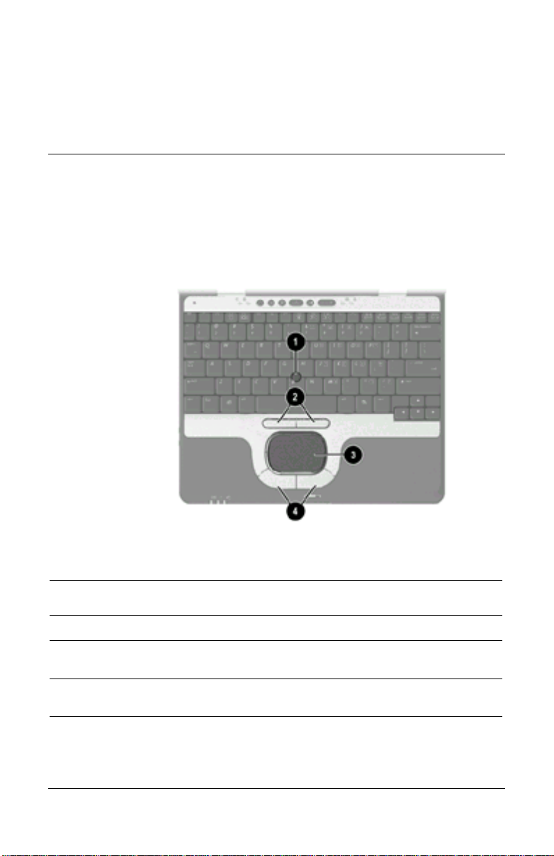
Pointing Device Components
1
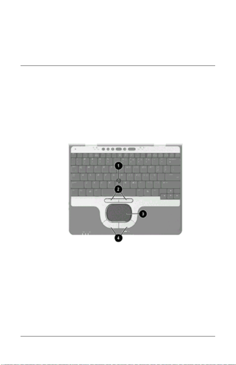
Pointing Device Components
Item Component Description
1
2
Hardware Guide 1-1
Pointing stick Moves the pointer and selects or
Left and right pointing stick
buttons
activates items on the screen.
Function like the left and right buttons on
an external mouse.
Page 8

Notebook Features
Pointing Device Components (Continued)
Item Component Description
3
4
TouchPad Moves the pointer and selects or
activates items on the screen. Can be
set to perform other mouse functions,
such as scrolling and double-clicking.
Left and right TouchPad
buttons
Function like the left and right buttons
on an external mouse.
1-2 Hardware Guide
Page 9
Top Components
Notebook Features
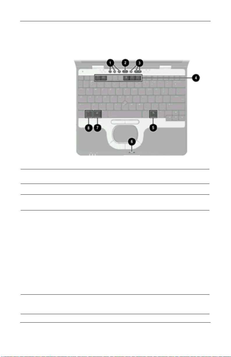
Top Components
Item Component Description
Quick Launch buttons (3) Enable you to access common functions
1
with a single keystroke.
Power button When the notebook is*
2
Off, press and release to turn on the
notebook.
In Standby, press and release to exit
Standby.
In Hibernation, press and release to
exit Hibernation.
If the system has stopped responding
and Windows shut down procedures
cannot be used, press and hold for 5
seconds to turn off the notebook.
*This table describes default settings. For information about changing the
functions of the power button and about using Standby and Hibernation, refer on
this CD to the Software Guide, “Power” chapter.
Hardware Guide 1-3
Page 10

Notebook Features
Top Components (Continued)
Item Component Description
3
4
5
6
7
8
Not
shown
Volume control buttons Increase, decrease, and mute the
system volume.
Function keys Execute frequently used system
functions when pressed in combination
with the
Applications key Displays shortcut menu for items
beneath the pointer.
Display release latch
recess
Microsoft logo key Displays the Windows Start menu.
Fn
key
Primary memory
compartment (not shown,
located under the
keyboard)
Secures the display when it is closed.
Executes frequently used system
functions when pressed in combination
with another key.
Contains the primary memory slot.
Fn key.
1-4 Hardware Guide
Page 11
Left Side Components
Notebook Features
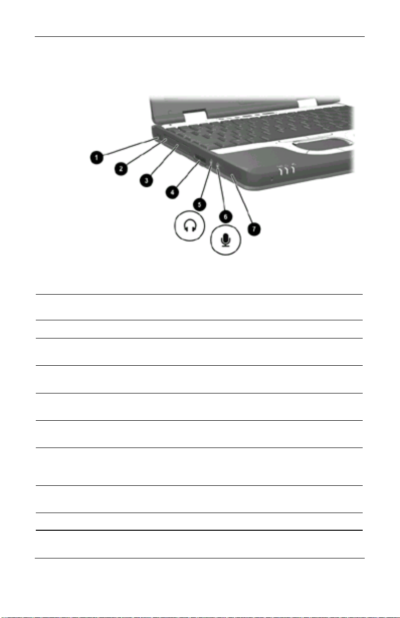
Left Side Components
Item Component Description
Infrared port Links another IrDA-compliant device
1
PC Card eject button Ejects an optional PC Card from the
2
PC Card slot Supports optional Type I or Type II 32-
3
Secure Digital (SD) slot Accepts SD memory cards used as
4
Audio line-out jack Connects optional powered stereo
5
Microphone input jack Connects an optional monaural
6
Speaker Produces system sound.
7
Hardware Guide 1-5
for wireless communication.
PC Card slot.
bit (CardBus) or 16-bit PC Cards.
removable storage devices.
speakers, headphones, headset, or
television audio.
microphone.
Page 12
Notebook Features
Right Side Components
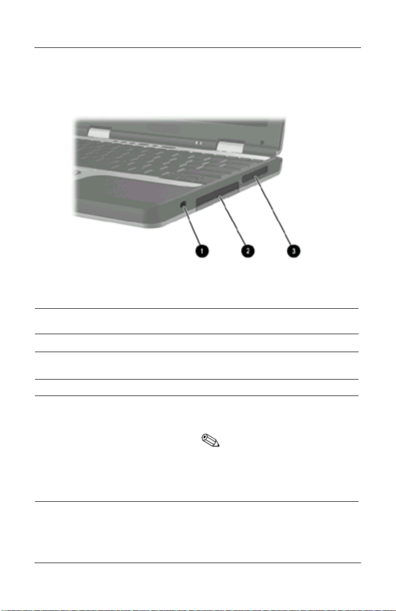
Right Side Components
Item Component Description
1
2
3
1-6 Hardware Guide
Security cable slot Attaches an optional security cable to
the notebook.
Hard drive bay Holds the primary hard drive.
Exhaust vent Enables airflow to cool internal
components.
To prevent overheating, do
not obstruct vents. Using the
notebook on a soft surface,
such as a pillow, blanket,
rug, or thick clothing may
block airflow.
Page 13
Front View Components
Notebook Features
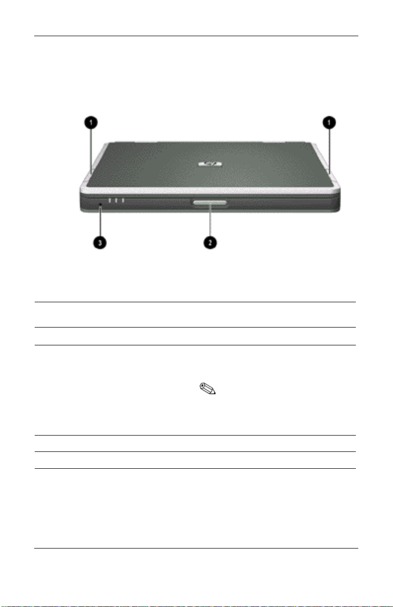
Front View Components
Item Component Description
1
2
3
Hardware Guide 1-7
Antenna (2) Send and receive wireless Local Area
Network (LAN) signals.
The antenna covers are not
removeable. Removing the
covers can cause damage
to the antenna.
Display release latch Opens the notebook.
Microphone Inputs single-channel sound.
Page 14
Notebook Features
Rear Panel Components
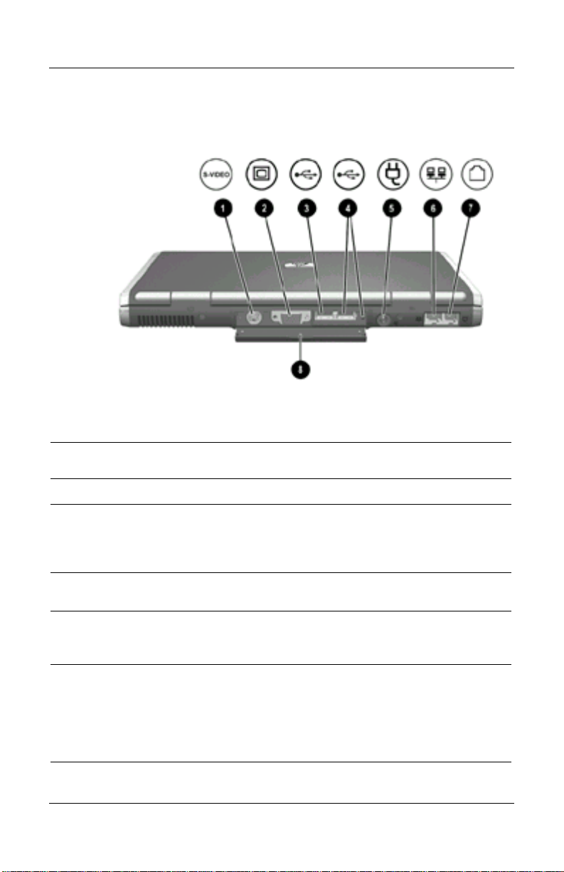
Rear Panel Components
Item Component Description
1
2
3
4
1-8 Hardware Guide
S-Video out jack Connects an optional S-Video device,
such as a television, VCR, camcorder,
overhead projector, or video
capture card.
External monitor connector Connects an optional external monitor
or overhead projector.
USB connector Connects USB 1.1- and 2.0-compliant
devices to the notebook using a
standard USB cable.
Self-powered USB
connector
Connects USB 1.1- and 2.0-compliant
devices to the notebook using a
standard USB cable, or an optional
External MultiBay to the notebook
using the External MultiBay-Powered
USB cable.
Page 15

Notebook Features
Rear Panel Components (Continued)
Item Component Description
5
6
7
8
DC power connector Connects an AC Adapter or an optional
Automobile Power Adapter/Charger,
Aircraft Power Adapter, or DC cable.
RJ-45 jack Connects a network cable.
RJ-11 jack Connects a modem cable.
Rear panel connector cover Closes to cover the connectors. This
cover can be removed by removing the
screws that secure it to the notebook.
Hardware Guide 1-9
Page 16
Notebook Features
Bottom Components
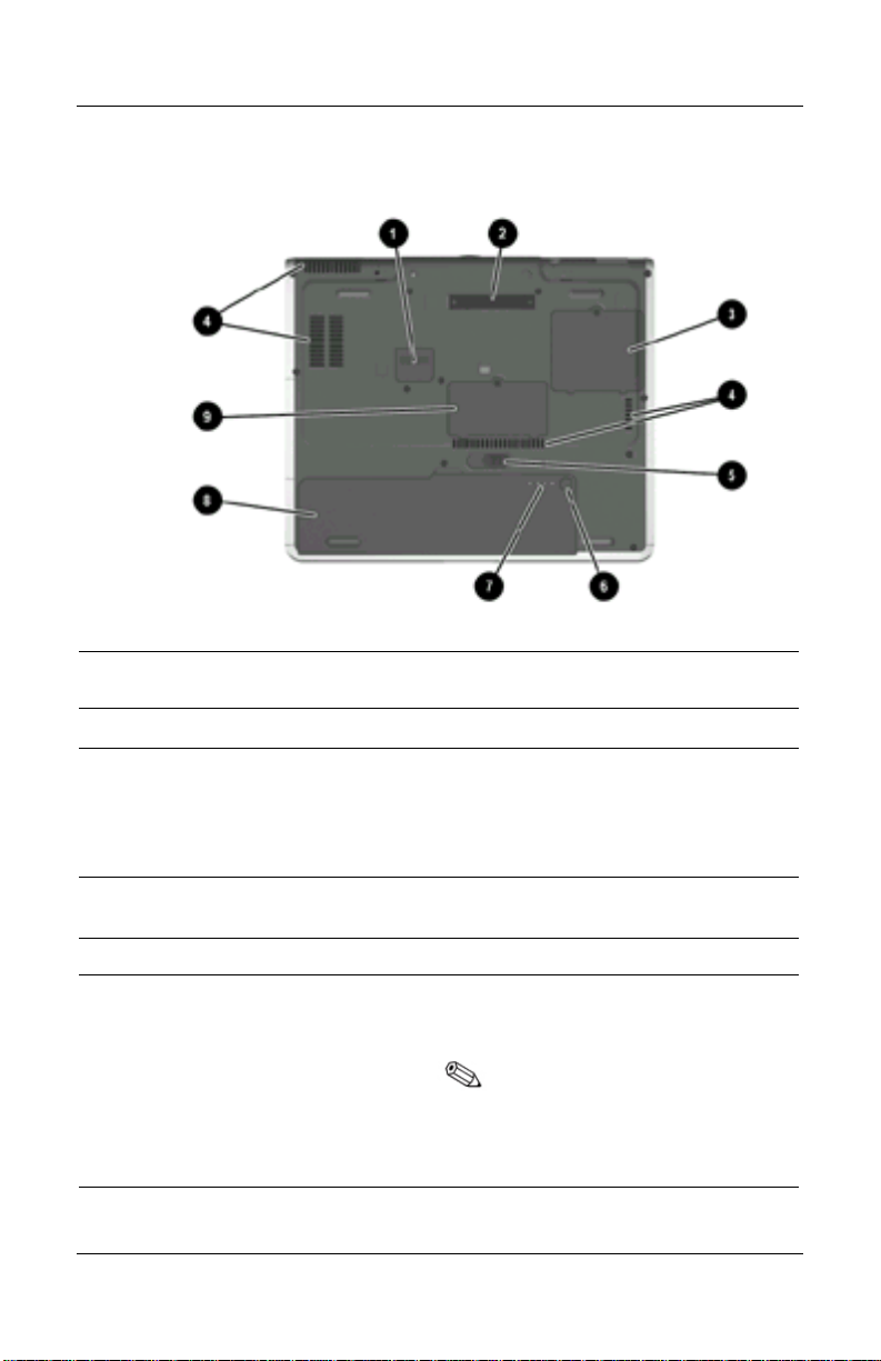
Bottom Components
Item Component Description
1
2
3
4
1-10 Hardware Guide
Travel battery connector Connects the optional travel battery
bay. The travel battery connector has a
plastic cover that must be opened
before connecting the travel
battery bay.
Docking connector Connects the notebook to an optional
Port Replicator.
Mini PCI compartment Contains the mini PCI wireless card.
Intake vents Enable airflow to cool internal
components.
To prevent overheating, do
not obstruct vents. Using the
notebook on a soft surface,
such as a pillow, blanket, rug,
or thick clothing may block
airflow.
Page 17

Bottom Components (Continued)
Item Component Description
5
6
7
8
9
Battery release latch Releases the primary battery pack
from the battery bay.
Quick Check button Displays the percentage of a full
charge remaining on a battery pack
using the Quick Check lights.
Battery power gauge Indicates the charge remaining on a
battery pack.
Battery bay Holds the primary battery pack.
Memory expansion
compartment
Contains 1 memory expansion slotfor
optional memory expansion boards.
Notebook Features
Hardware Guide 1-11
Page 18
Notebook Features
Lights
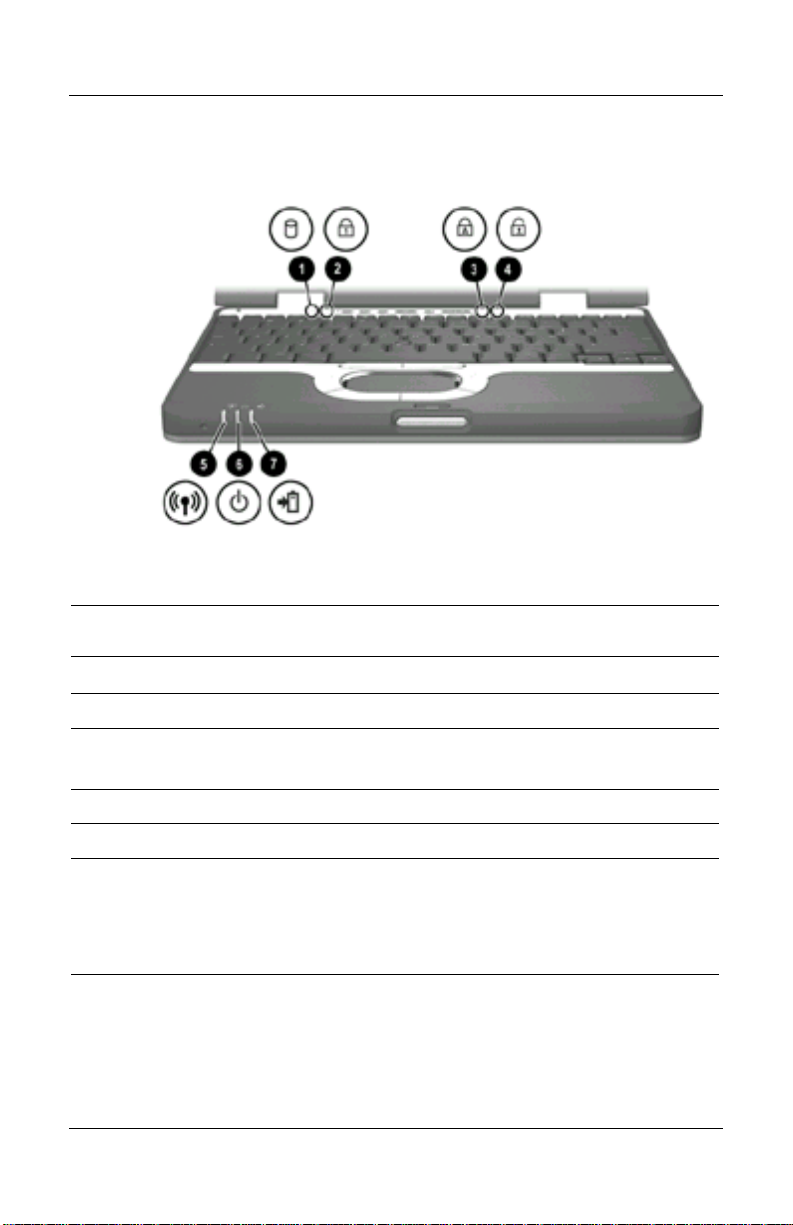
Lights
Item Component Description
1
2
3
4
5
1-12 Hardware Guide
Hard drive activity On: The hard drive is being accessed.
Num lock On: Num lock is on or the embedded
numeric keypad is enabled.
Caps lock On: Caps lock is on.
Scroll lock On: Scroll lock is on.
Wireless on/off
On: The wireless mini PCI card and/or
Bluetooth are on.
Off: The wireless mini PCI card and
Bluetooth are off.
Page 19

Lights (Continued)
Item Component Description
Notebook Features
6
7
Power/Standby On: Power is turned on. Blinking:
Notebook is in Standby.
Battery On: A battery pack is charging.
Blinking: A battery pack that is the only
available power source has reached a
low-battery condition. When the battery
reaches a critical low-battery condition,
the battery light begins blinking more
quickly.
Hardware Guide 1-13
Page 20
Pointing Devices and Keyboard
Using a Pointing Device
By default, the pointing stick and TouchPad components can be
used interchangeably.
2
Pointing device components
User Guide 2-1
Page 21

Pointing Devices and Keyboard
Pointing Device Components
Item Component Description
1
2
3
4
Pointing stick
Left and right pointing
stick button
TouchPad
Left and right TouchPad
buttons
Moves the pointer and selects or
activates items on the screen.
Functions like the left and right buttons
on an external mouse.
Moves the pointer and selects or
activates items on the screen. Can be
set to perform other mouse functions,
such as scrolling, selecting, and
double-clicking.
Functions like the left and right buttons
on an external mouse.
2-2 User Guide
Page 22
Using the Pointing Stick
To move the pointer, press the pointing stick in the direction
you want to move the pointer. Use the left and right pointing
stick buttons as you would the left and right buttons on an
external mouse.
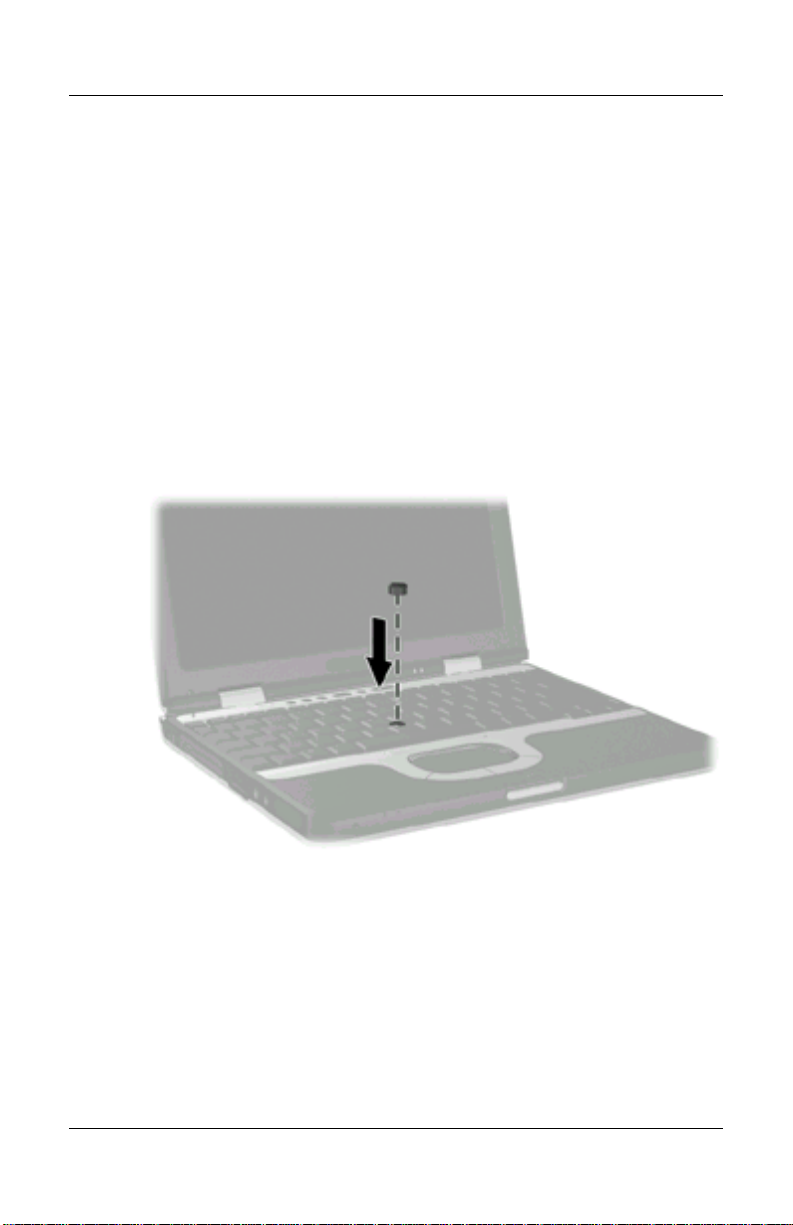
To change the pointing stick cap:
1. Turn off the notebook.
2. Gently pull off the used pointing stick cap.
3. Push a replacement cap, included with the notebook,
into place.
Pointing Devices and Keyboard
Replacing the pointing stick cap
Using the TouchPad
To move the pointer, slide your finger across the TouchPad
surface in the direction you want to move the pointer. Use the
left and right TouchPad buttons as you would the left and right
buttons on an external mouse.
User Guide 2-3
Page 23

Pointing Devices and Keyboard
Using an External Mouse
An external USB mouse can be connected to the notebook using
one of the USB connectors on the back panel. An external PS/2
or USB mouse can be connected to the system using the
connectors on an optional Port Replicator
Setting Pointing Device Preferences
Mouse Properties in Windows enables you to change custom
settings for pointing devices, including:
Enabling or disabling a pointing device.
TouchPad tapping, which enables you to tap the TouchPad
once to select an object or twice to double-click an object.
Edge motion, which enables you to continue to scroll even
thoug your finger has reached the edge of the TouchPad.
Palm Check, which helps prevent moving the pointer
unintentionally if your palms contact the TouchPad as you
type.
Other features, such as mouse speed preferences and mouse
trails, are also found in the Mouse Properties windows.
To access Mouse Properties:
In Windows 2000, select Start > Settings > Control Panel >
Mouse icon.
In Windows XP, select Start > Control Panel, Printers and
Other Hardware > Mouse icon.
2-4 User Guide
Page 24
Pointing Devices and Keyboard
Using Hotkeys and Shortcut Keys
Hotkeys and shortcut keys, which are preset combinations of the
Fn key and another key, execute frequently used system
functions.
Fn and Function Keys
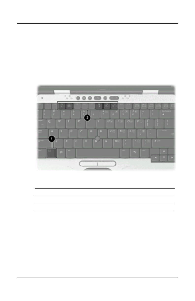
Fn and function keys
Item Component
Fn
1
2
key
Function keys
A hotkey is a combination of the Fn key and one of the function
keys. The icons on the function keys represent the hotkey
functions available on your notebook.
A shorcut key is a combination of the Fn key and a key other
than a function key.
User Guide 2-5
Page 25

Pointing Devices and Keyboard
Hotkey and Shortcut Key Quick Reference
Function
Initiate Standby
Switch display and
image
View battery information
Adjust the screen
brightness to a
lower level
Adjust the screen
brightness to a
higherlevel
Display system
information
Key Combination to
Activate Function
Fn+F3
Fn+F4 Fn+F4
Fn+F8 Fn+F8
Fn+F9
Fn+F10
Fn+esc Fn+esc
Key Combination to
DeactivateFunction
Power button
N/A
N/A
2-6 User Guide
Page 26

Initiating Standby (Fn+F3)
The Fn+F3 hotkeys are set at the factory to initiate Standby.
Pointing Devices and Keyboard
When the notebook is on, press the
Fn+F3 hotkeys to initiate
Standby. When Standby is limited, your work is saved in
random access memory (RAM), the screen is cleared, and
power is conserved. While the notebook is in Standby, the
power/Standby light blinks.
To exit Standby, briefly press the power button.
The function of the
Windows, can be changed. For example, the
Fn+F3 hotkeys, called the “sleep button” in
Fn+F3 hotkeys can
be set to initiate Hibernation instead of Standby. For more
information about Standby, Hibernation, and changing the
function of the Fn+F3 hotkeys, refer on this CD to the
Software Guide, “Power” section.
Switching Display and Image (Fn+F4)
The Fn+F4 hotkeys switch the image between the display and an
external display device connected to the notebook. Pressing
Fn+F4 switches the image among the notebook display, the
external display device, and a simultaneous display on the
notebook and the external device.
The following video transmission types are supported by the
Fn+F4 hotkeys:
LCD (notebook display)
External VGA (most external monitors and projectors)
S-video (televisions, camcorders, VCRs, and video capture
cards with S-video in jacks)
User Guide 2-7
Page 27

Pointing Devices and Keyboard
Viewing Battery Charge Information (Fn+F8)
Press Fn+F8 to display charge information for all installed battery
packs. The display indicates which battery packs are charging
and reports the amount of charge remaining in each battery pack.
Battery pack locations are indicated by number:
Location 1 is the primary battery pack.
Location 2 is the travel battery pack.
Adjusting the Screen Brightness (Fn+F9 and Fn+F10)
Pressing the Fn+F9 and the Fn+F10 hotkeys respectively increases
and decreases the display brightness to several levels of
brightness. Press
Fn+F10 to increase the brightness level. Holding down the
hotkeys changes the brightness level incrementally.
Fn+F9 to lower the brightness level, and press
Displaying System Information (Fn+esc)
Press Fn+esc to display information about system hardware
components and software version numbers. Press
second time to remove the system information from the screen.
The system BIOS date is the version number of the system
ROM. The BIOS date may display in a decimal format, for
example, 10/19/2002 F.07.
2-8 User Guide
Fn+esc a
Page 28

Pointing Devices and Keyboard
Using Hotkeys and Shortcut Keys with External Keyboards
The following hotkeys and shortcut keys can be used as
described with external keyboards:
Fn+esc
Fn+F8
To use hotkeys or shortcut keys on an external keyboard, press
the scroll lock key twice, then the other key of the hotkey
combination. For example, to use the
lock+scroll lock+F8.
Hotkeys and shortcut keys may not function on an external
keyboard connected through a USB connector if Quick Launch
Buttons software is not loaded. You can download the
appropriate software and drivers for your system at
For more information on software updates, refer on this CD to
the Software Guide, “Software Updates and Restorations”
chapter. For more information about Quick Launch buttons, refer
to “Using Quick Launch Buttons” later in this chapter.
Fn+F8 hotkeys, press scroll
www.hp.com
.
User Guide 2-9
Page 29
Pointing Devices and Keyboard
Using Quick Launch Buttons
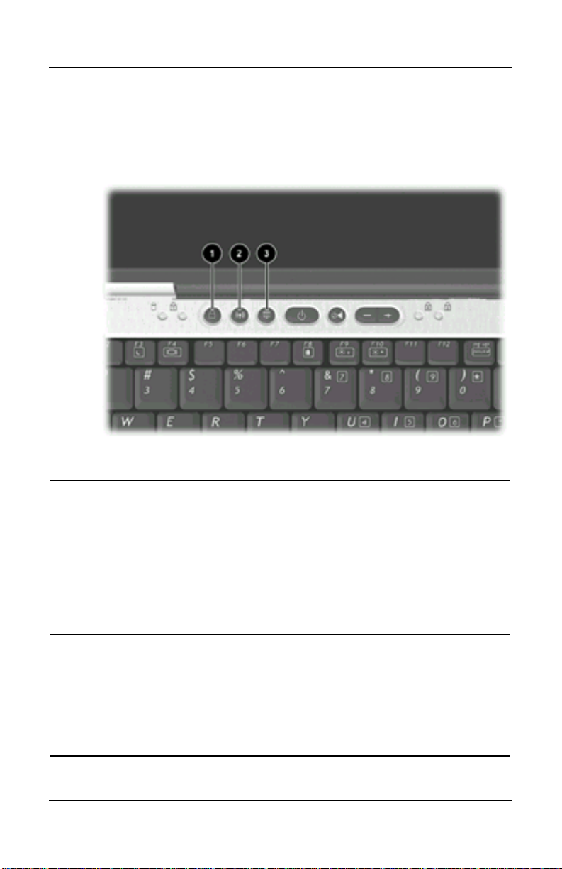
The 6 Quick Launch buttons enable you to access common
functions with a single keystroke.
Quick Launch buttons
Item Component Description
1
2
3
QuickLock button
Wireless On/Off button
Presentation Mode
button
Disables the keyboard and pointing device
and clears the display. Before you can use
QuickLock, you must set a password and
select preferences. For more information,
refer on this CD to the Software Guide,
“Security” chapter.
Turns the wireless LAN or Bluetooth
device on andoff.
Sets the notebook to presentation mode,
which opens a user-defined application,
folder, file, or Web site. The image
simultaneously displays on the notebook
screen and an external device connected
to the external monitor connector or SVideo out jack on the rear panel or to
connectors on an optional Port Replicator.
2-10 User Guide
Page 30
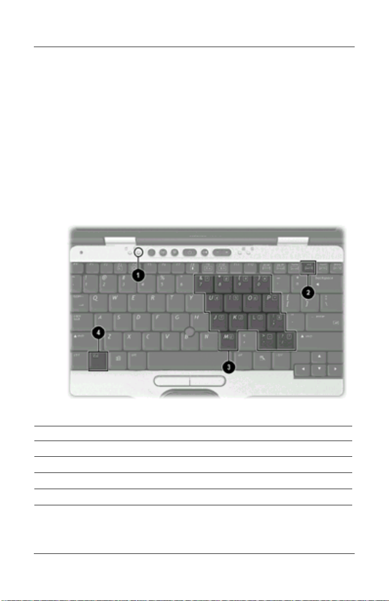
Keypads
The notebook has an internal numeric keypad and supports an
optional external numeric keypad or an optional external
keyboard that includes a numeric keypad.
Using the Internal Keypad
The 15 keys of the embedded numeric keypad can be used like
the keys on an external keypad. When the internal keypad is
turned on, each key on the internal keypad performs the
functions indicated by the icon in the upper right corner of the
key.
Pointing Devices and Keyboard
Embedded numeric keypad components
Item Component
1
2
3
4
User Guide 2-11
Num lock light
num lk key
Numeric keypad keys
Fn key
Page 31

Pointing Devices and Keyboard
Enabling and Disabling the Internal Keypad
Press Fn+num lk to enable the embedded numeric keypad. The
num lock light turns on. Press
Fn+num lk again to return the keys
to their standard keyboard functions.
The numeric keypad cannot be enabled while an optional
external keyboard or keypad is connected to the notebook or to
an optional Port Replicator.
Switching Key Functions on the Internal Keypad
You can temporarily switch the functions of keys on the internal
keypad between their standard keyboard functions and their
keypad functions by using the
combination.
To change the functions of a keypad key to keypad functions
while the keypad is off, press and hold the
pressing the keypad key.
To use the keypad keys temporarily as standard keys while
the keypad is on:
Press and hold the
Fn key or the Fn+shift key
Fn key while
Fn key to type in lowercase.
Press and hold the
Fn+shift to type in uppercase.
Using an External Keypad
Most keys on most external keypads function differently when
num lock mode is on than when num lock mode is off. For
example:
When num lock mode is on, most keyboard keys type
numbers.
When num lock mode is off, most keypad keys function like
arrow, page up, or page down keys.
2-12 User Guide
Page 32

Pointing Devices and Keyboard
When num lock mode on an external keypad is turned on, the
num lock light on the notebook turns on. When the num lock
mode on an external keypad is turned off, the num lock light on
the notebook turns off.
If the external keypad is connected, the internal keypad cannot
be turned on.
Enabling or Disabling Num Lock Mode as You Work
To turn num lock on or off on an external keypad as you work,
press the
Enabling or Disabling Num Lock Mode at Startup
To set the notebook to start up with a connected external keypad
in num lock mode, set your preference in Computer Setup. For
more information about using Computer Setup, refer on this CD
to the Software Guide, “Computer Setup” chapter.
To set the notebook to start up with the external keypad enabled:
1. Turn on or restart the notebook.
2. Press
3. Select Advanced > Device Options, then press enter.
4. Select or clear the Num Lock State at Boot field:
num lk key on the external keypad, not on the notebook.
F10 while the F10 = ROM Based Setup message is
displayed in the lower left corner of the screen.
To change the language, press F2.
For navigation instructions, press
F1.
To start up an external keypad with num lock mode turned
on, select the field.
To start up an external keypad with num lock mode turned
off, clear the field.
User Guide 2-13
Page 33

Pointing Devices and Keyboard
5. Press F10.
6. To save your preference and exit Computer Setup, select
File > Save Changes and Exit, then follow the instructions on
the screen.
Your preference is set as you exit Computer Setup and is in
effect when the notebook restarts.
2-14 User Guide
Page 34

3
Battery Packs
This notebook supports up to 2 lithium ion battery packs, the
primary battery and an optional travel battery. The same type of
battery pack can be used in the notebook battery bay and the
optional travel battery.
Battery pack
Hardware Guide 3-1
Page 35

Battery Packs
Inserting or Removing the Primary Battery Pack
The notebook battery bay holds the primary battery pack.
CAUTION: To prevent the loss of information when removing a
battery pack, when it is the only power source available to the
system, initiate Hibernation or shut down the notebook before
removing the battery pack.
To insert the primary battery pack:
1. Align the battery pack with the notebook battery bay.
2. Insert the battery pack tabs into the battery bay recesses.
Inserting the battery pack tabs into the battery bay recesses
3-2 Hardware Guide
Page 36

Battery Packs
3. Snap the battery pack into place.
Inserting the primary battery pack
4. Turn the notebook over and open the display. If the notebook
is in Hibernation, press the power button to resume operation.
Hardware Guide 3-3
Page 37

Battery Packs
To remove the primary battery pack:
1. Close the display and turn the notebook bottom-side up.
2. Slide the battery release latch 1
.
3. After the battery pack tilts upward, remove it from the battery
2
.
bay
Removing the primary battery pack
3-4 Hardware Guide
Page 38

Using the Optional Travel Battery
The optional travel battery attaches to the bottom of the
notebook. The optional travel battery kit includes the following
items:
Travel battery caddy
Battery pack
Documentation
Inserting or Removing the Battery Pack
To insert the battery pack into the travel battery caddy:
1. Align the battery pack with the travel battery caddy.
2. Insert the battery pack tabs into the travel battery
caddy recesses.
Battery Packs
Inserting the battery pack tabs into the travel battery
caddy recesses
Hardware Guide 3-5
Page 39

Battery Packs
3. Snap the battery pack into place.
Inserting the battery pack into the travel battery caddy
To remove the battery pack from the travel battery caddy:
1. Eject the battery pack from the travel battery caddy by sliding
the battery release latch
2. When the battery pack tilts upward, remove it from the travel
battery caddy
2
1
.
.
Removing a battery pack from the travel battery caddy
3-6 Hardware Guide
Page 40

Battery Packs
Attaching or Detaching the Travel Battery
To attach the optional travel battery to the notebook:
1. Open the travel battery connector on the bottom of the
notebook by sliding the cover toward the rear panel of
the notebook.
Opening the optional travel battery connector
Hardware Guide 3-7
Page 41

Battery Packs
2. Insert the tabs on the travel battery caddy into the recesses on
the bottom of the notebook.
Inserting the travel battery caddy tabs into the notebook
recesses
3. Press the travel battery caddy onto the notebook until it snaps
into place.
Attaching the optional travel battery
3-8 Hardware Guide
Page 42

Battery Packs
4. Lock the travel battery onto the notebook by sliding the
locking switch.
Locking the optional travel battery onto the notebook
Hardware Guide 3-9
Page 43

Battery Packs
To detach an optional travel battery from the notebook:
1. Unlock the travel battery from the notebook by sliding the
locking switch
1
.
2. Press the release latch
2
.
3. Lift the travel battery up and away from the notebook
Detaching the travel battery from the notebook
Charging a Battery Pack
Multiple battery packs in the system charge and discharge in a
preset sequence:
3
.
Charge sequence
1. Notebook battery bay
2. Travel battery
Discharge sequence
1. Travel battery
2. Notebook battery bay
3-10 Hardware Guide
Page 44

Battery Packs
The primary battery pack charges when it is inserted into the
notebook and the notebook is connected to external power.
External power can be supplied through an AC Adapter, the
optional Port Replicator, or an optional Automobile Power
Adapter/Charger.
The battery pack in the travel battery charges when it is attached
to the notebook and the notebook is connected to external power.
External power can be supplied through an AC Adapter or an
optional Automobile Power Adapter/Charger. Because the travel
battery covers the docking connector, the travel battery cannot be
used or charged with a Port Replicator.
Battery packs can also be charged in the optional Universal
Charger. The optional Aircraft Power Adapter can be used to run
the notebook, but cannot be used to charge a battery pack.
While the battery pack is charging, the battery light on the
notebook is on. The light turns off when the battery pack is fully
charged.
Battery light
Hardware Guide 3-11
Page 45

Battery Packs
To charge the primary battery pack:
1. Insert the battery pack into the notebook.
2. Connect the notebook to AC power. (The battery light turns
on.)
3. Leave the notebook connected to AC power until the battery
light turns off, signaling that the battery pack is fully charged.
To charge the battery pack in the travel battery:
1. Insert the battery pack into the travel battery caddy.
2. Attach the travel battery to the notebook.
3. Connect the notebook to AC power. (The battery light
turns on.)
4. Leave the notebook connected to AC power until the battery
light turns off, signaling that the battery pack is fully charged.
Monitoring the Charge of a Battery Pack
To increase the accuracy of all battery charge displays:
Allow a battery pack to discharge to less than 5 percent of a
full charge through normal use before charging it.
When you charge a battery pack, charge it fully.
If a battery pack has not been used for one month or more,
calibrate the battery pack instead of simply charging it. For
calibration instructions, refer to “Calibrating a Battery Pack”
later in this chapter.
3-12 Hardware Guide
Page 46

Battery Packs
Displaying Charge Information on the Screen
To display battery charge information on the screen, use the
Power meter feature of the operating system:
Select Start > Control Panel > Performance and Maintenance
icon > Power Options icon > Power Meter tab.
or
Select the Power meter icon in the system tray.
To display the Power meter icon in the system tray:
1. Select Start > Control Panel > Performance and Maintenance
icon > Power Options icon > Advanced tab.
2. Select the Always Show Icon On The Taskbar check box.
3. Select the OK button.
Most charge displays report battery status in both percent
and time:
The percent indictes the amount of charge remaining in the
battery pack.
The time indicates the approximate running time remaining
on the battery pack if the battery pack continues to provide
power at the current level. For example, the time remaining
will decrease if you start playing a DVD and will increase if
you stop playing a DVD.
Most charge displays identify battery packs by location:
Location 1 is the notebook battery bay.
Location 2 is the optional travel battery.
In some displays, a lightening bolt icon may be displayed beside
a battery pack location. This icon indicates that the battery pack
is being charged.
Hardware Guide 3-13
Page 47

Battery Packs
Displaying Charge Information on a Battery Pack
The battery Quick Check feature enables you to check the
battery pack charge information without having to turn on the
notebook. You do not have to remove a battery pack from the
notebook battery bay or the travel battery to check the charge
information; however, you must detach the travel battery from
the notebook to check the charge of the travel bay battery pack.
To display the percentage of a full charge remaining on a battery
1
pack, press the Quick Check button
Quick Check lights
2
on the battery pack indicate the charge
remaining, as shown in the following table.
on the battery pack. The
Battery pack Quick Check button and lights
3-14 Hardware Guide
Page 48

Battery Packs
Battery Pack Quick Check Indications
Indication Percent of a Full Charge Remaining
4 lights on 76 to 100%
3 lights on 51 to 75%
2 lights on 26 to 50%
1 light on 11 to 25%
1 light blinking 1 to 10%
Managing Low-Battery Conditions
Some low-battery condition alerts and system responses can be
changed in the Power Options Properties window of the
operating system. The information in this chapter describes the
alerts and system responses set at the factory. For information
about setting preferences in the Power Options Properties
window, refer on this CD to the Software Guide, “Power”
chapter, “Setting Power Preferences” section.
Identifying Low-Battery Conditions
The notebook has alerts for 2 types of low-battery conditions: a
low-battery condition and a critical low-battery condition.
Low-Battery Condition
When a battery pack that is the only power source available
reaches a low-battery condition (10 percent of a full charge), the
battery light flashes.
Hardware Guide 3-15
Page 49

Battery Packs
Critical Low-Battery Condition
If a low-battery condition is not resolved, the notebook enters a
critical low-battery condition (one percent of a full charge). In a
critical low-battery condition:
If Hibernation is enabled and the notebook is on or in
Standby, the notebook initiates Hibernation.
If Hibernation is disabled and the notebook is on or in
Standby, the notebook remains in Standby until there is no
power, then shuts down and loses your unsaved work.
For more information about Hibernation and Standby, refer on
this CD to the Software Guide, “Power” chapter.
Resolving Low-Battery Conditions
CAUTION: If the notebook has reached a critical low-battery
condition and has initiated Hibernation, do not press the power
button until Hibernation is complete. Hibernation is complete when
the power light turns off.
When a Charged Battery Pack is Available
To resolve a low-battery condition when a charged battery pack
is available, turn off the notebook or initiate Hibernation, insert a
charged battery pack, then turn on the notebook.
When External Power Is Available
To resolve a low-battery condition when external power is
available, select one of the following options:
Connect the AC Adapter.
Plug an optional Automobile Power Adapter/Charger into
the notebook and into a vehicle cigarette lighter receptacle.
3-16 Hardware Guide
Page 50

Plug an optional Aircraft Power Adapter into the notebook
and into the in-seat power supply available on some
commercial aircraft. (The optional Aircraft Power Adapter
can run the notebook but cannot charge a battery power.)
Dock the notebook in an optional Port Replicator.
When No Power Source Is Available
To resolve a low-battery condition when no power source is
available, select one of the following options:
Initiate Hibernation.
In Windows 2000 Professional, select Start > Shut
down > Hibernate, then select the OK button.
In Windows XP, select Start > Turn Off the Computer >
Hibernate. (If the Hibernate option is not displayed,
press the
Save your work and shut down the notebook.
shift key).
Battery Packs
When the Notebook Cannot Exit Hibernation
To resolve a low-battery condition if the notebook lacks the
power to exit Hibernation:
1. Insert a charged battery pack or connect external power.
2. Exit Hibernation by briefly pressing the power button.
Calibrating a Battery Pack
To calibrate a battery pack manually, follow the instructions in
the following sections. To initiate an unattended calibration in an
optional Universal Charger, follow the instructions included with
the device.
Hardware Guide 3-17
Page 51

Battery Packs
When to Calibrate
Calibrate an in-use battery pack whenever battery status displays
seem inaccurate or whenever the battery pack has not been used
for one month or more. It should not be necessary to calibrate
any battery pack, even if it is heavily used, more than once a
month, unless usage patterns change significantly. It is not
necessary to calibrate a new battery pack before first use.
How to Calibrate
To manually calibrate a battery pack:
1. Fully charge the battery pack.
2. Fully discharge the battery pack.
While discharging the battery pack, be sure that your power
settings are not configured to initiated Hibernation. For more
information on power settings, refer on this CD to the Software
Guide, “Power” chapter.
3. Fully recharge the battery pack.
Conserving Battery Power
Using the following battery conservation procedures and settings
extends the time that a battery pack can run the notebook from a
single charge.
Conserving Power as You Work
To conserve power as you use the notebook:
Turn off wireless and LAN connections and exit modem
applications when you are not using them.
Disconnect external devices you are not using that are not
connected to an external power source.
3-18 Hardware Guide
Page 52

Battery Packs
Stop or remove a PC Card or SD card that you are not using.
Use the
Fn+F9 and the FN+F10 hotkeys to quickly lower and
raise screen brightness as you need it.
Use optional powered speakers instead of the internal
speakers, or use the volume buttons to quickly raise and
lower system volume as needed.
Turn off a device connected to the S-Video connector by
using the
Fn+F9 hotkeys or by turning off support for the
device in Windows.
Run the notebook on external power while formatting a
diskette.
If you leave work, initiate Standby or Hibernation or shut
downthe notebook.
Selecting Power Conservation Settings
To set the notebook to conserve power:
Select a short wait for the screen saver and select a screen saver
with minimal graphics and motion. Access screen saver setting
by selecting Start > Control Panel > Appearance and Themes >
Display icon > Screen Saver tab.
Follow the instruction on this CD in the Sofware Guide, “Power”
section, to:
In the operating system, select a Power Scheme with low
power-use settings.
In SpeedStep, select the Battery Optimized mode or
Maximum Battery Mode (Windows XP Professional only).
Hardware Guide 3-19
Page 53

Battery Packs
Storing a Battery Pack
If a notebook will be unused and not connected to external
power for more than 2 weeks, remove and store the battery pack.
CAUTION: To prevent damage to a battery pack, do not expose it
to high temperatures for an extended time.
High temperatures accelerate the self-discharge rate of a stored
battery pack. To prolong the charge of a stored battery pack,
store it in a cool, dry place within the following temperature
ranges.
Battery Storage Temperature Ranges
Storage Time Temperature Range °C Temperature Range °F
Less than
1 month
No more than
3 months
No more than
6 months
0°–50° 32°–122°
0°40° 32°104°
0°30° 32°86°
Disposing of a Used Battery Pack
WARNING: There is a risk of fire and chemical burn if a battery
pack is handled improperly. Do not disassemble, crush, or
puncture a battery pack or short the contacts on a battery pack. Do
not expose a battery pack to temperatures higher than 60°C
(140°F) or dispose of a battery pack in water or fire.
When a battery pack has reached the end of its useful life, do not
dispose of it in general household waste. For more information
about battery pack precautions and disposal, and the complete
text of governmental agency notices, refer on this CD to the
Regulatory and Safety Notices guide
3-20 Hardware Guide
Page 54

Finding More Power Information
For more information about using Standby and Hibernation,
conserving power, setting power preferences, and using other
power management features, refer on this CD to the Software
Guide, “Power” chapter.
Battery Packs
Hardware Guide 3-21
Page 55

Caring for Drives
Hard drives are fragile notebook components that must be
handled with care. Read carefully the following general caution
notices. Caution notices specific to individual procedures are
provided throughout this chapter with the procedures to which
they apply.
CAUTION: To prevent loss of work or damage to the notebook or a
drive:
Handle the drive carefully.
Do not drop the drive.
Keep in mind that excessive force can damage drive connectors.
When you insert the drive, use only enough pressure to seat the
drive.
Do not spray the drive with a cleaner or other liquid or expose it to
extreme temperatures.
Do not remove the primary hard drive (the hard drive in the hard
drive bay) except for repair or replacement.
Avoid exposing a hard drive to devices with a magnetic field, such
as airport walk-through metal detectors and security wands.
If you mail the drive, ship it in packaging that protects it from shock,
vibration, temperature, and humidity. Label the package
“FRAGILE”.
CAUTION:
drive:
To prevent electrostatic damage to the notebook or a
Discharge yourself from static electricity before handling a drive by
touching a grounded metal object.
Avoid touching the connectors on a drive. For more information
about preventing electrostatic damage, refer on this CD to the
Regulatory and Safety Notices.
4
Hard Drive
Hardware Guide 4-1
Page 56

Hard Drive
Airport security devices that check carry-on luggage placed on a
conveyor belt use X-rays instead of magnetics and do not
damage hard drives.
Hard Drive Activity Light
The hard drive activity light turns on when the hard drive is
being accessed.
Hard drive activity light
4-2 Hardware Guide
Page 57

Replacing the Primary Hard Drive
The hard drive in the hard drive bay is the primary hard drive.
CAUTION: To prevent system lockup and loss of information:
Shut down the notebook before removing the hard drive from the
hard drive bay. Do not remove the hard drive while the notebook is
on, in Standby, or in Hibernation.
If you are not sure whether the notbook is in Hibernation, turn on
the notebbok and then shutit down.
To replace the primary hard drive:
1. Save your work.
2. Shut down the notebook and close the display.
3. Turn the notebook bottom-side up.
4. Remove the hard drive retaining screw.
Hard Drive
Removing the hard drive retaining screw
Hardware Guide 4-3
Page 58

Hard Drive
5. Slide the bottom half of the front bezel upward to create a
handle.
Extending the front bezel to create a handle
6. Pull the drive out of the bay.
Removing the hard drive from the hard drive bay
4-4 Hardware Guide
Page 59

Hard Drive
7. Insert a hard drive by sliding the hard drive into the bay until
the drive is seated.
Inserting the hard drive into the hard drive bay
8. Close the front bezel of the hard drive.
Closing the hard drive bezel
Hardware Guide 4-5
Page 60

Hard Drive
9. Reinsert the hard drive retaining screw. (If you removed but
did not replace a hard drive, put the retaining screw in a safe
place.)
Replacing the hard drive retaining screw
4-6 Hardware Guide
Page 61

Using Audio Features
The notebook includes the following audio components:
5
Audio and Video
Audio Components
Hardware Guide 5-1
Audio components
Item Component Description
Mute button Mutes system volume.
1
2
3
Volume buttons (2) Adjust the system volume.
Audio line-out jack
Connects optional, powered stereo
speakers, headphones, headset, or
television audio.
Page 62

Audio and Video
Audio Components (Continued)
Item Component Description
Microphone input jack
4
Speaker Produces system sound.
5
Microphone Inputs single-channel sound.
6
Connects an optional monaural
microphone.
Adjusting the Volume
To adjust the volume, use any of the following controls:
Notebook volume buttons
Tomute or restore volume, press Quick Launch mute
button. You can also mute or restore volume by pressing
the volume – and volume + buttons simultaneously.
To decrease the volume, press the left button.
To increase the volume, press the right button.
Windows Volume Control
Volume can also be adjusted within some applications.
5-2 Hardware Guide
Page 63

Using the Microphone Input Jack
When an external microphone is connected to the notebook, the
notebook microphone is disabled.
When connecting a microphone to the microphone input jack,
use a monaural microphone with a 3.5-mm plug.
Using the Audio Line-Out Jack
WARNING: To reduce the risk of personal injury, adjust the
volume before putting on headphones or a headset.
CAUTION: To prevent possible damage to an external device, do
not plug a single-sound channel (monaural) connector into the
audio line-out jack.
When connecting a device to the audio line-out jack, use only a
3.5-mm stereo plug. For best sound quality, use 24-ohm to 32-
ohm headphones.
When an external audio device is connected to the audio-out
jack, the notebook stereo speaker is disabled.
Audio and Video
Using Video Features
The notebook features an S-Video out jack. An S-Video cable
attaches the notebook to an optional S-Video device, such as a
television, VCR, camcorder, overhead projector, or video
capture card. The notebook supports one S-Video device
connected to the S-Video out jack while simultaneously
supporting an image on the notebook display and on any other
supported external display.
Hardware Guide 5-3
Page 64

Audio and Video
To transmit video signals through the S-Video out jack, you need
an S-Video cable available from most electronic retailers. If you
are combining audio and video functions, such as playing a
movie from a DVD in an optional MultiBay drive to a television,
you also need a standard audio cable available from most
electronics retailers.
Connecting a Device to the S-Video Out Jack
To connect a video device to the S-Video out jack:
1. Plug either end of the S-Video cable into the S-Video out jack
on the notebook
2. Connect the other end of the cable to the video device as
instructed in the documentation included with the device
1
.
2
.
Connecting a device to the S-Video out jack
If the S-Video out jack on the notebook is not accessible while
the notebook is docked, you can connect the device to the SVideo out jack on the optional Port Replicator.
5-4 Hardware Guide
Page 65

Changing the Video Mode
The default color television standard mode of the notebook is
NTSC. Color television standard modes vary even within
regions. However, NTSC is common in North America; PAL is
common in Europe, China, Africa, and the Middle East; NTSC-J
is common in Japan; and PAL-M is common in Brazil. Other
South and Central American regions may use NTSC, PAL, or
PAL-M.
To change the color television standard mode from NTSC:
1. Access the ATI Display tab:
In Windows 2000, select Start > Settigs > Control Panel.
Double-click the Display icon, select the Settings tab, select
the Advanced button, then elect the ATI Displys tab.
In Windows XP, Start > Control Panel. Double-click the
Display icon, select the Settings tab, select the Advanced
button, then elect the ATI Displys tab.
2. Enable the TV by selecting the Enable button, indicated by a
red triangle.
Audio and Video
3. Select the TV Header, then select the Format tab.
4. Select a television format either by name or by
Country/Region:
To select a format by name, select Format, select a format in
the drop-down list, the select the OK button.
To select the default format for a region or country, select
Country/Region, select a location I the drop-down list, then
select the OK button.
5. Select the Close button to close all opened dialog boxes.
6. At the prompt, restart the notebook.
Hardware Guide 5-5
Page 66

Communication Devices
Connecting a Modem Cable
A modem cable, which has a 6-pin RJ-11 connector at each end,
must be connected to an analog telephone line. Jacks for digital
PBX systems may resemble analog telephone jacks, but are not
compatible with the modem.
WARNING: Connecting the notebook to a digital line can
permanently damage the modem. Immediately disconnect your
modem cable if accidentally connected to a digital line.
If the modem cable contains noise suppression circuitry, which
prevents interference from TV and radio reception, orient the
circuitry end of the cable toward the notebook.
6
RJ-11 modem cable with noise suppression circuitry
Hardware Guide 6-1
Page 67

Communication Devices
Using the RJ-11 Cable
To connect an RJ-11 modem cable:
1. Plug the modem cable into the RJ-11 jack on the notebook
WARNING: To reduce the risk of electrical shock, fire, or damage
to the equipment, do not plug a telephone cable into the RJ-45
network jack.
2
2. Plug the modem cable into the RJ-11 telephone jack
Connecting the RJ-11 modem cable
.
1
.
For more information about using the modem or about using AT
commands and dial modifiers, refer on this CD to the Modem
and Networking guide or the Modem Command Guidelines
(Advanced Users Only) guide.
6-2 Hardware Guide
Page 68

Communication Devices
Using a Country-Specific Adapter Cable
Telephone jacks vary by country. To use the modem and the RJ11 cable outside the country in which you purchased the
notebook, you must obtain a country-specific modem adapter.
Refer on this CD to the Modem and Networking guide for more
details about using your notebook internationally.
To connect the modem to an analog telephone line that does not
have an RJ-11 telephone jack:
1. Plug the modem cable into the RJ-11 jack on the notebook
WARNING: To reduce the risk of electrical shock, fire, or damage
to the equipment, do not plug a telephone cable into the RJ-45
network jack.
2. Plug the modem cable into the country-specific
2
modem adapter
.
3. Plug the country-specific modem adapter into the
3
telephone jack
.
1
.
Connecting a modem cable using a modem adapter
Hardware Guide 6-3
Page 69

Communication Devices
Connecting a Network Cable
A network cable has an 8-pin RJ-45 connector at each end. If the
network cable contains noise suppression circuitry, which
prevents interference from TV and radio reception, orient the
circuitry end of the cable toward the notebook.
RJ-45 network cable with noise suppression circuitry
6-4 Hardware Guide
Page 70

Communication Devices
To connect the network cable:
1. Plug the network cable into the RJ-45 jack on the
1
notebook
.
2. Plug the other end of the cable into a network jack
2
.
Connecting a network cable
3. Start or restart the notebook.
4. Connect to the network.
Linking to an Infrared Device
The notebook is IrDA-compliant—4 megabits per second
(Mbps) standard—and can communicate with another infraredequipped device that is also IrDA-compliant.
Hardware Guide 6-5
Page 71

Communication Devices
Infrared signals are sent through an invisible beam of infrared
light and require an unobstructed line of sight path.
Linking to an infrared device
The infrared port supports both low-speed connections of up to
115 kilobits per second (Kbps) and high-speed connections of up
to 4 Mbps. Infrared performance may vary depending on the
performance of infrared peripherals, distance between infrared
devices, and applications used.
Setting Up an Infrared Transmission
For information about using infrared software, refer to your
operating system Help file.
To set up infrared devices for optimal transmission:
Prepare the infrared ports on both devices for transmission.
Position the devices so that their infrared ports face one
another at a distance no greater than 1 meter (3.3 feet).
Position the ports so that they face one another directly.
Because the maximum capture angle is 30 degrees, the ports
must be aligned no more than 15 degrees off-center.
6-6 Hardware Guide
Page 72

Sheild ports from direct sunlight, flashing incandescent light,
and energy-saving fluorescent light.
Be sure that no signals from remote control or other wireless
devices, such as headphones or audio devices, aim at a port.
During the transmission, do not move either device and do
not allow objects or movement to disrupt the beam.
Using Standby with Infrared
Standby is not compatible with infrared transmission. If the
notebook is in Standby, an infrared transmission cannot be
initiated. If Standby is initiated during an infrared transmission,
the transmission stops. To resume from Standby, press the power
button. The transmission resumes when the notebook resumes
from Standby. However, any program that was using the infrared
transmission when Standby was initiated may not continue at the
point it was stopped. For example, if a program was printing
when Standby was initiated, the program resumes transmission
after the notebook resumes, but the print job may not resume.
Communication Devices
Using Wireless LAN
The notebook provides internal wireless LAN supported through
an optional mini PCI device. For more information on using your
internal wireless LAN, refer to the wireless LAN documentation
that ships with the notebook.
Using Bluetooth
The notebook provides internal wireless Bluetooth connectivity
supported through an optional integrated module. For more
information on using your internal Bluetooth module, refer to the
wireless Bluetooth documentation that ships with the notebook.
Hardware Guide 6-7
Page 73

7
External Devices
The jacks and connectors described in this guide support
standard external devices.
For information about which jack or connector to use, refer
to the documentation included with the device.
For information about installing or loading any software,
such as drivers, required by the device, refer to the
documentation included with the device.
To connect a standard external device to the notebook:
1. Turn off the notebook.
2. If you are connecting a powered device, turn off the device.
3. Connect the device to the connector on the notebook.
4. If you are connecting a powered device, plug the device
power cord into a grounded electrical outlet.
5. Turn on the device.
6. Turn on the notebook.
To disconnect a standard external device from the notebook, turn
off the device, then disconnect the device from the notebook.
Hardware Guide 7-1
Page 74

External Devices
Connecting a Monitor or Projector
To connect an external monitor or projector to the notebook,
insert the monitor cable into the external monitor connector on
the back of the notebook.
If a properly connected external monitor or projector does not
display an image, try pressing the Fn+F4 hotkeys to switch the
image to the monitor.
Using a USB Device
Universal serial bus (USB) is a hardware interface that can be
used to connect external devices, such as a USB keyboard,
mouse, drive, printer, scanner, or hub, to the notebook. The
notebook has a USB connector
connects an optional powered external MultiBay
connectors support USB 2.0 and USB 1.1 devices.
1
and a USB connector that also
2
. The USB
USB connectors on the rear panel
7-2 Hardware Guide
Page 75

USB hubs can be connected to a USB connector on the notebook
or on an optional Port Replicator, or to other USB devices. Hubs
support varying numbers of USB devices and are used to
increase the number of USB devices in the system. Powered
hubs must be connected to external power. Unpowered hubs
must be connected either to a USB connector on the notebook or
to a port on a powered hub.
Using a USB Device
A USB device functions in the same way as a comparable nonUSB device, with one exception. By default, USB devices do not
function unless an operating system that supports USB is loaded.
Some USB devices may require additional support software,
which is usually included with the device. For more information
and software installation instructions, refer to the documentation
included with the device.
Enabling USB Legacy Support
External Devices
You must enable USB legacy support to:
Use a USB keyboard, mouse, or hub connected to a USB
connector on the notebook during startup or in a nonWindows application or utility.
Boot from an optional external MultiBay.
To enable USB legacy support:
1. Turn on or restart the notebook.
2. Press
F10 while the F10 = ROM Based Setup message is
displayed in the lower left corner of the screen.
To change the language, press
F2.
For navigation instructions, press F1.
3. Select Advanced menu > Device Options.
Hardware Guide 7-3
Page 76

External Devices
4. Select Enable USB legacy support.
5. To save your preference and exit Computer Setup, select
File > Save Changes and Exit, then follow the instructions on
the screen.
Using an Optional External MultiBay
An external MultiBay connects to the notebook by way of the
self-powered USB connector and enables you to use MultiBay
drives. For more information about the external MultiBay, refer
to the documentation that is included with the device.
Connecting an external MultiBay
7-4 Hardware Guide
Page 77

External Devices
Connecting an Optional Cable Lock
To install a security cable:
1. Loop the security cable around a secured object.
2. Pull the security cable lock through the cable loop and insert
the cable
3. If the cable has a key
1
into the security cable slot on the notebook.
2
, use it to lock and unlock the cable.
Connecting a security cable
Hardware Guide 7-5
Page 78

To order hardware or learn more about upgrades and accessories,
visit the HP Web site at
dealer, reseller, or service provider. For information about
obtaining and installing software updates and upgrades, refer on
this CD to the Software Guide, “Software Updates and
Restorations” chapter.
Using PC Cards
A PC Card is a credit card-sized accessory designed to conform
to the standard specifications of the Personal Computer Memory
Card International Association (PCMCIA). The notebook
supports both 32-bit CardBus and 16-bit PC Cards, and it
supports Type I and Type II cards. Zoomed video PC Cards are
not supported.
CAUTION: If you install all of the software or any of the enablers
provided by a PC Card manufacturer, you may not be able to use other
PC Cards. If you are instructed by the documentation included with your
PC Card to install device drivers:
Install only the device drivers for your operating system.
Do not install other software, such as card services, socket
services, or enablers, that may also be supplied by the PC Card
maunfacturer.
8
Hardware Upgrades
http://www.hp.com
or contact an authorized
Hardware Guide 8-1
Page 79

Hardware Upgrades
Inserting a PC Card
CAUTION: To prevent damage to the connectors:
Use minimal pressure when inserting a PC Card into a PC Card slot.
Do not move or transport the notebook while a PC Card is inserted.
To insert a PC Card:
1. Hold the PC Card label-side up with the connector facing the
notebook.
2. Gently push the card into the slot until the card is seated.
Inserting a PC Card into the PC Card slot
Removing a PC Card
CAUTION: To prevent loss of work or system lockup, stop the
PC Card, according to the instructions that follow, before
removing it.
8-2 Hardware Guide
Page 80

Hardware Upgrades
To remove a PC Card:
1. Stop the PC Card:
In Windows 2000, select the Safety Remove Hardware icon
in the taskbar, then stop the card you plan to remove. (When
the card can be safely removed, a message is displayed.)
In Windows XP, select the Safety Remove Hardware icon
in the taskbar, then select the PC Card. (To display the
Safely Remove Hardware icon, select Show Hidden Icons in
the taskbar.)
2. Press the PC Card eject button
3. Gently pull out the card
Removing a PC Card
2
1
.
.
An inserted PC Card uses power even when not in use. To
conserve power, stop or remove a PC Card when you are not
using it.
Hardware Guide 8-3
Page 81

Hardware Upgrades
Using SD Cards
Secure Digital (SD) cards are removeable postage stamp-sized
compact flash storage devices that provide a convenient method
of storing data and sharing it with other devices such as PDAs,
cameras, and other SD equipped PCs.
Inserting an SD Card
CAUTION: To prevent damage to the connectors:
Use minimal pressure when inserting an SD card into an SD card
slot.
Do not move or transport the notebook while an SD card is inserted,
To insert an SD card:
1. Insert the SD card into the SD slot.
2. Push the card firmly into the slot until it clicks into place.
Inserting an SD card into the SD slot
8-4 Hardware Guide
Page 82

Removing an SD Card
CAUTION: To prevent loss of work or system lockup, stop the SD
card before removing it.
To remove an SD card:{xe "SD (Secure Digital) card:removing"}
1. Close all files and applications using the SD card.
2. Stop the SD card.
In Windows 2000, select the Unplug or Eject icon in the
task bar, then stop the card you plan to remove. (When the
card can be safely removed, a message is displayed.)
In Windows XP, select the Safely Remove Hardware icon
in the taskbar, then select the PC Card. (To display the
Safely Remove Hardware icon, select Show Hidden Icons in
the taskbar.)
Hardware Upgrades
3. Gently press in on the SD card to unlock it
2
4. Pull the SD card from the slot
Ejecting an SD card from the SD slot
Hardware Guide 8-5
.
1
.
Page 83

Hardware Upgrades
Adding and Upgrading Memory Modules
WARNING: The memory compartments are the only user-
accessible internal compartments on the notebook. All other areas
that require a tool to access should be opened only by an
authorized service provider.
WARNING: Failure to unplug the power cord and remove all
battery packs before installing a memory expansion board can
damage the equipment and expose you to the risk of electrical
shock.
CAUTION: Electrostatic discharge (ESD) can damage electronic
components. Before beginning any procedure, ensure that you are
discharged of static electricity by touching a grounded metal
object. For more information, refer on this CD to the Regulatory
and Safety Notices guide.
The notebook has 2 memory slots. The primary memory slot is
located under the keyboard. The primary memory slot is
populated at the factory. The memory expansion slot is located
on the bottom of the notebook.{xe "memory:primary slot"}
The memory capacity of the notebook can be upgraded first by
adding a memory module to the expansion slot and then by
upgrading the memory module in the primary memory slot.
Adding a Memory Expansion Module
To add a memory expansion module:
1. Shut down the notebook. (If you are not sure whether the
notebook is off or in Hibernation, turn the notebook on by
pressing the power button. Then shut down the notebook
through the operating system.)
2. Disconnect all external devices connected to the notebook.
3. Disconnect the power cord.
8-6 Hardware Guide
Page 84

Hardware Upgrades
4. Turn the notebook bottom-side up.
5. Remove any battery packs from the notebook.
6. Remove the screw from the memory expansion slot cover
2
7. Tilt the expansion slot cover away from the notebook
.
1
.
Removing the expansion slot cover
8. Remove the memory expansion slot cover.
Hardware Guide 8-7
Page 85

Hardware Upgrades
9. Insert the memory expansion module:
a. Align the keyed (notched) edge of the module with the
keyed area in the expansion slot
b. Press the module into the slot from a 45-degree angle
until it is seated, then push the board downward until the
retention clips snap into place
2
1
.
.
Inserting a memory expansion module
8-8 Hardware Guide
Page 86

Hardware Upgrades
10. Insert the tabs on the expansion slot cover into the recesses
in the expansion slot
1
.
11. Replace the expansion slot cover over the expansion
module compartment.
12. Replace the expansion slot cover screw 2
.
13. Replace the battery packs.
14. Reconnect AC power and external devices.
15. Restart the notebook.
Upgrading the Memory Module in the Primary Memory Slot
To upgrade the memory module in the primary memory slot:
1. Shut down the notebook. (If you are not sure whether the
notebook is off or in Hibernation, turn the notebook on by
pressing the power button. Then shut down the notebook
through the operating system.)
2. Disconnect all external devices connected to the notebook.
Hardware Guide 8-9
Page 87

Hardware Upgrades
3. Disconnect the power cord.
4. Remove any battery packs from the notebook.
5. Remove the 3 keyboard screws from the bottom of the
notebook. A keyboard icon is located next to the keyboard
screws.
Removing the keyboard screws
8-10 Hardware Guide
Page 88

Hardware Upgrades
6. Using a fingernail or small flat tool, remove the Quick
Launch button bezel located above the keyboard.
Removing the Quick Launch button bezel
7. Remove the keyboard.
Removing the keyboard
Hardware Guide 8-11
Page 89

Hardware Upgrades
8. Remove the existing memory module:
a. Pull away the retention clips on each side of the
module
b. Lift the edge of the memory expansion module, then
gently pull it out of the slot
1
. (The module tilts upward.)
2
.{xe "slots:memory"}
Removing the existing memory module
To protect a memory module after it has been removed, place it
in an static-safe container.
8-12 Hardware Guide
Page 90

9. Insert the new memory module:
a. Align the keyed (notched) edge of the module with the
keyed area in the expansion slot
b. Press the module into the slot from a 45-degree angle until
it is seated, then push the module downward until the
retention clips snap into place
2
1
.
Hardware Upgrades
.
Inserting the new memory module
10. Replace the keyboard.
11. Replace the Quick Launch button bezel.
12. Replace the keyboard screws located on the bottom of the
notebook.
13. Replace the battery packs.
14. Reconnect AC power and external devices.
15. Restart the notebook.
Hardware Guide 8-13
Page 91

Hardware Upgrades
Increasing RAM
You can increase the random access memory (RAM) of the
notebook with optional memory expansion modules. When
RAM increases, the operating system increases the hard drive
space reserved for the hibernation file.
If you experience problems with Hibernation after increasing
RAM, verify that your hard drive has enough free space for the
larger hibernation file.
To display the amount of RAM in the system:
In Windows 2000, select Start > Settings > Control Panel
> System > General tab.
In Windows XP, select Start > Control Panel >
Performance and Maintenance > System > General tab.
In Windows 2000 or Windows XP, press
Fn+esc.
To display the amount of free space on your hard drive:
Double-click the My Computer icon on the desktop, then
select your hard drive. Information about the space on the
drive is displayed in a status bar at the bottom of the window.
To display the amount of space required by the hibernation file:
In Windows 2000, select Start > Settings > Control
Panel > HP Power > Hibernation tab.
In Windows XP, select Start > Control Panel >
Performance and Maintenance > Power Options icon >
Hibernate tab.
8-14 Hardware Guide
Page 92

Notebook Dimensions
Dimension Metric U.S.
Height 2.79 cm 1.1 inches
Width 27.94 cm 11 inches
Depth 23.37 cm 9.2 inches
Operating Environment
Factor Metric U.S.
Temperature
Operating 10° to 35° C 50° to 95° F
Nonoperating
10° to 60° C 14° to 140° F
9
Specifications
Relative humidity (noncondensing)
Operating 10 to 90% 10 to 90%
Nonoperating
Maximum altitude (unpressurized)
Operating 3,048 m 10,000 ft
Nonoperating 9,144 m 30,000 ft
Hardware Guide 9-1
5 to 95% 5 to 90%
Page 93

Specifications
Rated Input Power
Input Power Rating
Operating voltage 100120/220240 VAC RMS
Operating current 1.6/0.8 A RMS
Operating frequency range
When powered by a DC source
This product is designed for IT power systems in Norway
with phase-to-phase voltage not exceeding 240 Vrms.
Modem Specifications
Factor Specification
Temperature
Operating 0° to 75° C (32° to 167° F)
Storage
40° to 75° C (40° to 167° F)
5060 Hz AC
18.5V MAX
Relative humidity (noncondensing)
Operating 10 to 90%
Nonoperating
Interfaces
Power
5 to 95% @ 39° C (5 to 95% @ 102° F)
Communications
connector
+3.3 volts ±5%, +5 volts ±5%
Standard RJ-11
connector
Requirements
9-2 Hardware Guide
Page 94

Index
A
adapter, modem 6–3
Aircraft Power Adapter
(optional)
analog vs. digital line
antenna
applications key
audio devices, connecting
external
audio line-out jack
5–3
Automobile Power
Adapter/Charger (optional)
1–9, 3–11, 3–16
B
battery charge information
displays
hotkey
in Windows
interpreting
on battery pack
battery packs
battery light
calibrating
charging
conserving power
discharge sequence
disposing of 3–20
1–9, 3–11, 3–17
1–7
1–4
5–3
2–6, 2–8
3–13
3–15
1–13, 3–11
3–17
3–10
6–1
1–5, 5–1
3–14
3–18
3–10
,
low-battery conditions
monitoring charge of
storing
type
battery power
conserving
low-battery conditions
running notebook on
battery Quick Check
battery, primary
bay
inserting
release latch
removing
battery, travel
attaching
connector
detaching
inserting battery pack
locking switch
removing battery pack
Bluetooth
brightness, display
3–20
3–1
1–11
2–10, 6–7
3–18
3–2
1–11
3–4
3–7
1–10, 3–7
3–10
3–9
3–12
3–1
3–14
2–6
3–15
3–15
3–5
3–6
Hardware Guide Index-1
Page 95

Index
buttons
2–10, 5–1
mute
PC Card eject
pointing stick
power
Presentation Mode
Quick Launch
Quick Lock
TouchPad
volume control
wireless on/off
C
cable lock
connecting
slot
cables
modem
network
security
calibration, battery pack
cap, replacing pointing stick
2–3
caps lock light
charge sequence
compartments
expansion memory
mini PCI (peripheral
primary memory
1–3
1–6
component interconnect)
1–10
1–5, 8–3
1–1, 2–1
1–3, 2–10
2–10
1–2, 2–1
2–10
7–5
6–1, 6–2
6–4
1–6, 7–5
1–12
3–10
5–1
1–4
2–10
3–17
1–11
Computer Setup
enabling num lock mode at
1–8
6–3
2–13
1–9
1–10
2–8
2–13, 7–3
1–8
1–8
1–9
1–10, 3–7
2–9, 7–1, 8–1
6–1
9–1
3–10
1–4, 1–7
1–10
7–1
startup
enabling USB legacy support
7–3
navigating in
connecting external drvices
connector(s)
DC power
docking
external monitor
External MultiBay
rear panel cover
travel battery
USB
country-specific modem cable
adapter
critical low-battery condition
3–16
D
DC power connector 1–9
device drivers
digital vs. analog line
dimensions, notebook
discharge sequence
display
brightness
release latch
switching image to or from
2–6, 2–7, 7–2
docking connector
Index-2 Hardware Guide
Page 96

Index
E
embedded numeric keypad 2–12
enabling
internal keypad
num lock mode
environmental specifications
9–1
exhaust vent
external devices (optional)
external keypad (optional)
external monitor connector
external mouse (optional)
External MultiBay connector
1–8
F
Fn key 1–4, 2–5, 2–9, 2–11
function keys
H
hard drive
activity light
bay
1–6
caring for
inserting
removing
replacing
retaining screw
1–6
1–4, 2–5
1–12, 4–2
4–1
4–5
4–3
4–3
4–3, 4–6
2–12
2–13
7–1
2–12
1–8
2–4
headphones
Hibernation
and low-battery conditions
3–16
and removing a hard drive
4–3
exiting
file space requirements for
8–14
initiating
initiating for battery removal
3–2
initiating to conserve power
3–19
hotkeys
defined
shortcut reference to
commands
with external keyboards
hub, USB
humidity specifications
I
increasing RAM 8–14
infrared
linking to a drvice
port
transmissions
using Standby with
intake vent
1–5
5–3
1–3
2–7
2–5
7–3
1–10
2–6
6–6
6–5
9–1
6–7
2–9
Hardware Guide Index-3
Page 97

Index
J
jack(s)
audio line-out
microphone input
5–3
1–9, 6–1
RJ-11
RJ-45
1–9
S-Video out
K
key(s)
application
1–4, 2–5, 2–9, 2–12
Fn
function
hotkeys
internal keyboard
Microsoft logo
num lk
shortcut
keyboard
external (optional)
USB
7–3
keypads
enabling/disabling
external (optional)
internal
L
LAN, wireless 6–7
latches
battery release
display release
5–3
1–4
1–4, 2–9
2–5, 2–9
2–12
2–5, 2–9
2–11
1–7
1–5, 5–1, 5–3
1–5, 5–2
2–12
1–4
2–12
1–11
2–9
2–12
,
light
battery
caps lock
hard drive activity
num lock
power/Standby
scroll lock
wireless on/off
lock, security cable (optional)
7–5
low-battery conditions
identifying
resolving
M
magnetic fields, protecting
drives from
maximum altitude
memory
adding memory expansion
expansion compartment
primary slot
upgrading primary board
microphone input jack
5–2, 5–3
microphone, internal
Microsoft logo key
mini PCI (peripheral
component interconnect),
compartment 1–10
1–13, 3–11
1–12
4–2
1–12, 2–11
3–16
4–1
8–6
board
1–11, 8–6
8–9
1–13
1–12
1–12
3–15
9–1
1–4, 8–6
1–4
,
1–12
,
1–5
1–7, 5–2
Index-4 Hardware Guide
Page 98

Index
modem
6–1, 6–2
cable
6–2
country-specific adapter
6–3
jack
1–9
Modem and Networking guide
6–2
Modem Command Guidelines
(Advanced Users Only)
monitor, external (optional)
connecting
connector
mouse, external
MultiBay, external (optional)
7–4
mute button
N
network
cable
jack
noise suppression circuitry
6–1, 6–4
NTSC color television format
5–5
num lock
key
light
numeric keypad
O
operating current 9–2
7–1
1–8
2–4
5–1
6–4, 6–5
1–9
2–12
1–12, 2–12
2–12
operating environment
7–1
2–6, 7–2
1–5, 8–3
8–2
8–1
8–1
1–2, 2–1
9–1
9–2
8–1
7–1
2–3
9–2
8–3
specifications
operating frequency range
oprating voltage
overhead projector (optional)
connecting
external monitor connector
1–8
switching display to or
from
switching image to or from
2–7
P
PAL, PAL-M television formats
5–5
PC Card
eject button
inserting
slot
1–5
stopping and removing
types
using
zoomed video
peripherals, connecting and
disconnecting
pointing device preferences
2–4
pointing stick
buttons
cap, replacing
location
1–1, 2–1
Hardware Guide Index-5
Page 99

Index
Port Replicator (optional)
charging a battery pack
3–11
with
docking connecter
external device
connections
using the travel battery with
3–11
8–14
1–11
1–7
1–9
1–9
7–1
1–5, 6–6
1–3
1–8
port, infrared
power button
power connector
power, rated input
power/Standby light
powered USB
presentation mode button
primary battery pack
projector (optional),
connecting
Q
Quick Check, battery 3–14
Quick Launch buttons
2–10
R
RAM (Random Access
Memory)
rated input power
relative humidity
release latch
battery
display
RJ-11 jack
RJ-45 jack
2–4
1–9
9–2
9–1
9–2
1–13
3–2
1–10
1–3
2–10
,
S
screen brightness 2–6, 2–8
scroll lock light
SD (Secure Digital) card
inserting
removing
slot
1–5
security cable slot
security features
shortcut keys
defined
with external keyboards
2–9
slots
memory
PC Card
SD card
speaker, internal
audio line-out jack
identifying
speakers, external (optional)
audio line-out jack
connecting
specifications, notebook
Standby
and low-battery conditions
and removing a hard drive
4–3
exiting
initiating to conserve
power
initiating with hotkey
2–7
light
1–13
using with infrared
1–12
8–4
8–5
1–6
7–5
2–5
1–4, 8–7, 8–12
1–5, 8–2
1–5, 8–4
1–5, 5–2
5–3
1–3, 2–7
3–19
6–7
1–5
5–1
9–1
2–6
3–16
,
Index-6 Hardware Guide
Page 100

Index
S-Video
connecting cable
jack
1–8, 5–4
switching display and image
,
2–7, 7–2
6
system information
T
telephone (RJ-11) jack
identifying
modem cable
television (optional)
changing color mode
connecting audio
connecting video
S-Video out jack
switching image to or from
2–6, 2–7
temperature
battery storage
operating
TouchPad
buttons
location
using
travel battery
attaching
charge sequence
connector
detaching
inserting battery pack
locking switch
removing battery pack
9–1
1–2, 2–1
1–2, 2–1
2–3
3–7
1–10, 3–7
3–10
1–9
6–1, 6–2
3–20
3–10
3–9
5–4
2–6, 2–8
5–5
5–4
5–4
1–8, 5–4
3–5
3–6
traveling with the notebook
Aircraft Power Adapter
(optional)
2–
Automobile Power
Adapter/Charger (optional)
1–9, 3–11, 3–16
protecting hardware
connectors
Types I and II PC Cards
U
USB
connectors
devices
hubs
legacy support
with power connector
V
VCR (optional)
connecting audio
connecting video
switching image to or from
2–6, 2–7, 7–2
vents
exhaust
intake
video devices (optional)
S-Video out jack
switching image to or from
2–6, 2–7, 7–2
volume controls
1–9, 3–11, 3–17
8–2, 8–4
1–8, 7–3
7–3
7–3
1–6
1–10
8–1
7–3
5–4
1–8, 5–3
1–8, 5–4
5–1, 5–2
1–8
Hardware Guide Index-7
 Loading...