

Page 1

HP ProLiant BL40p Server Blade
Setup and Installation Guide
January 2004 (Second Edition)
Part Number 307153-002
Page 2

© Copyright 2003, 2004 Hewlett-Packard Development Company, L.P.
The information contained herein is subject to change without notice. The only warranties for
HP products and services are set forth in the express warranty statements accompanying such
products and services. Nothing herein should be construed as constituting an additional
warranty. HP shall not be liable for technical or editorial errors or omissions contained herein.
Microsoft, Windows, and Windows NT are U.S. registered marks of Microsoft Corporation.
Intel, Pentium, Itanium, and the Intel Xeon are trademarks or registered trademarks of Intel
Corporation or its subsidiaries in the United States and other countries.
Java is a US trademark of Sun Microsystems, Inc.
Linux is a U.S. registered trademark of Linus Torvalds.
HP ProLiant BL40p Server Blade Setup and Installation Guide
January 2004 (Second Edition)
Part Number 307153-002
Page 3

Contents
About This Guide
Audience Assumptions..................................................................................................... vii
Important Safety Information........................................................................................... vii
Symbols on Equipment .................................................................................................... vii
Rack Stability .................................................................................................................... ix
Symbols in Text.................................................................................................................ix
Related Documents..............................................................................................................x
Getting Help ........................................................................................................................x
Technical Support....................................................................................................... xi
HP Website ................................................................................................................. xi
Authorized Reseller .................................................................................................... xi
Optional Installation Service............................................................................................ xii
Reader’s Comments ......................................................................................................... xii
Chapter 1
Installing the Server Blade and Options
Preparation Procedures.................................................................................................... 1-2
Accessing Internal Server Blade Components.......................................................... 1-2
Removing the System Board Tray Assembly........................................................... 1-7
Identifying System Board Components .................................................................. 1-15
Memory ......................................................................................................................... 1-17
Online Spare Memory Configuration ..................................................................... 1-17
DIMM Installation Guidelines................................................................................ 1-18
Installing DIMMs ................................................................................................... 1-19
Processors......................................................................................................................1-21
Battery-Backed Write Cache Enabler ........................................................................... 1-25
HP ProLiant BL40p Server Blade Setup and Installation Guide iii
Page 4

Contents
Hot-Plug SCSI Hard Drives and Blanks........................................................................1-26
Removing Hard Drive Blanks .................................................................................1-26
SCSI ID Numbers....................................................................................................1-28
Installing Hot-Plug SCSI Hard Drives ....................................................................1-29
Removing Hot-Plug SCSI Hard Drives...................................................................1-30
Installing Expansion Boards....................................................................................1-31
Server Blades...........................................................................................................1-33
Installing a Server Blade .........................................................................................1-33
Powering Up the Server Blade ................................................................................1-37
Chapter 2
Configuring and Deploying Server Blades
Configuration and Deployment Overview.......................................................................2-1
Remote Deployment using RDP ...............................................................................2-1
Remote Deployment using Virtual Devices through iLO .........................................2-2
Deployment using Local Devices with the I/O Cable............................................... 2-4
SAN Support..................................................................................................................2-14
Software and Utilities ....................................................................................................2-14
Integrated Lights-Out Management ........................................................................2-15
Redundant ROM Support........................................................................................2-19
Remote ROM Flash.................................................................................................2-20
ROMPaq Utility ......................................................................................................2-21
ROM-Based Setup Utility .......................................................................................2-21
Option ROM Configuration for Arrays Utility .......................................................2-23
PXE Deployment.....................................................................................................2-24
SmartStart Scripting Toolkit ...................................................................................2-26
Insight Manager 7....................................................................................................2-27
Diagnostics Utility...................................................................................................2-28
Automatic Server Recovery-2.................................................................................2-29
Integrated Management Log ...................................................................................2-29
Appendix A
Regulatory Compliance Notices
Regulatory Compliance Identification Numbers ............................................................A-1
Federal Communications Commission Notice ...............................................................A-1
Modifications ...........................................................................................................A-1
Cables....................................................................................................................... A-2
Canadian Notice (Avis Canadien) ..................................................................................A-2
iv HP ProLiant BL40p Server Blade Setup and Installation Guide
Page 5

European Union Notice.................................................................................................. A-2
Japanese Notice .............................................................................................................. A-2
Korean Notice................................................................................................................. A-3
BSMI Notice................................................................................................................... A-3
Battery Replacement Notice........................................................................................... A-3
Appendix B
Electrostatic Discharge
Preventing Electrostatic Damage ....................................................................................B-1
Grounding Methods.........................................................................................................B-2
Appendix C
Server Error Messages
Appendix D
Troubleshooting
When the Server Blade Does Not Start .......................................................................... D-1
Server Blade Diagnostic Steps................................................................................. D-4
System Configuration Switch Procedures.............................................................. D-11
Problems After Initial Boot .......................................................................................... D-14
Contents
Appendix E
LEDs and Switches
LEDs................................................................................................................................E-1
Server Blade Front Panel LEDs................................................................................E-1
System Board LEDs..................................................................................................E-3
Hot-Plug SCSI Hard Drive LEDs.............................................................................E-5
Fan LEDs ..................................................................................................................E-7
Power On/Standby Button...............................................................................................E-8
System Switches............................................................................................................E-10
System Maintenance Switch (SW3) .......................................................................E-11
System ID Switch (SW1)........................................................................................E-12
Appendix F
Specifications
ProLiant BL40p Server Blade .........................................................................................F-1
HP ProLiant BL40p Server Blade Setup and Installation Guide v
Page 6

Contents
Appendix G
System Battery
System Board Battery Replacement ...............................................................................G-1
Index
vi HP ProLiant BL40p Server Blade Setup and Installation Guide
Page 7

This guide provides step-by-step instructions for installation, and reference
information for operation, troubleshooting, and future upgrades for the HP
ProLiant BL40p server blade.
Audience Assumptions
This guide is intended for network administrators and IT personnel who install,
configure, and troubleshoot system hardware and software.
Important Safety Information
Before installing this product, read the Important Safety Information document
included with the server.
About This Guide
The installation and maintenance of this equipment may involve access to
high-power circuitry and must be performed by trained service personnel familiar
with these conditions. This equipment is intended to be installed in restricted areas,
such as equipment closets and data centers, where only trained service personnel are
permitted to operate and service the equipment.
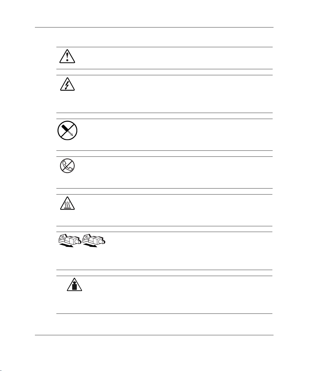
Symbols on Equipment
The following symbols may be placed on equipment to indicate the presence of
potentially hazardous conditions:
HP ProLiant BL40p Server Blade Setup and Installation Guide vii
Page 8
About This Guide
Weight in kg
Weight in lb
WARNING: This symbol, in conjunction with any of the following symbols,
indicates the presence of a potential hazard. The potential for injury exists if
warnings are not observed. Consult the documentation for specific details.
This symbol indicates the presence of hazardous energy circuits or electric
shock hazards. Refer all servicing to qualified personnel.
WARNING: To reduce the risk of injury from electric shock hazards, do not
open this enclosure. Refer all maintenance, upgrades, and servicing to
qualified personnel.
This symbol indicates the presence of electric shock hazards. The area
contains no user or field serviceable parts. Do not open for any reason.
WARNING: To reduce the risk of injury from electric shock hazards, do not
open this enclosure.
This symbol on an RJ-45 receptacle indicates a network interface connection.
WARNING: To reduce the risk of electric shock, fire, or damage to the
equipment, do not plug telephone or telecommunications connectors into this
receptacle.
This symbol indicates the presence of a hot surface or hot component. If this
surface is contacted, the potential for injury exists.
WARNING: To reduce the risk of injury from a hot component, allow the
surface to cool before touching.
These symbols, on power supplies or systems, indicate that the
equipment is supplied by multiple sources of power.
WARNING: To reduce the risk of injury from electric shock,
remove all power cords to completely disconnect power from the
system.
This symbol indicates that the component exceeds the recommended
weight for one individual to handle safely.
WARNING: To reduce the risk of personal injury or damage to the
equipment, observe local occupational health and safety requirements
and guidelines for manual material handling.
viii HP ProLiant BL40p Server Blade Setup and Installation Guide
Page 9
Rack Stability
WARNING: To reduce the risk of personal injury or damage to the equipment,
be sure that:
• The leveling jacks are extended to the floor.
• The full weight of the rack rests on the leveling jacks.
• The stabilizing feet are attached to the rack if it is a single-rack installation.
• The racks are coupled together in multiple-rack installations.
• Only one component is extended at a time. A rack may become unstable if
more than one component is extended for any reason.
Symbols in Text
These symbols may be found in the text of this guide. They have the following
meanings.
WARNING: Text set off in this manner indicates that failure to follow directions
in the warning could result in bodily harm or loss of life.
About This Guide
CAUTION: Text set off in this manner indicates that failure to follow directions could
result in damage to equipment or loss of information.
IMPORTANT: Text set off in this manner presents essential information to explain a concept
or complete a task.
NOTE: Text set off in this manner presents additional information to emphasize or supplement
important points of the main text.
HP ProLiant BL40p Server Blade Setup and Installation Guide ix
Page 10

About This Guide
Related Documents
For additional information on the topics covered in this guide, refer to the following
documentation:
• HP ProLiant BL p-Class System Setup and Installation Guide
• HP ProLiant BL p-Class System Maintenance and Service Guide
• HP ProLiant BL p-Class System Hardware Installation and Configuration Poster
• ProLiant BL System Best Practices Guide
• ProLiant BL System Common Procedures Guide
• HP ProLiant Servers Troubleshooting Guide
• HP Integrated Lights-Out User Guide
• HP ROM-Based Setup Utility User Guide
• HP ProLiant Support Pack and Deployment Utility User Guide
• SmartStart Scripting Toolkit User Guide
• White Paper: HP ProLiant BL p-Class System Over and Planning
• HP ProLiant BL p-Class QuickSpecs
• HP ProLiant BL40p server blade QuickSpecs
• HP ProLiant BL p-Class Multimedia
Getting Help
If you have a problem and have exhausted the information in this guide, you can get
further information and other help in the following locations.
x HP ProLiant BL40p Server Blade Setup and Installation Guide
Page 11

Technical Support
In North America, call the HP Technical Support Phone Center at 1-800-652-6672.
This service is available 24 hours a day, 7 days a week. For continuous quality
improvement, calls may be recorded or monitored. Outside North America, call the
nearest HP Technical Support Phone Center. Telephone numbers for worldwide
Technical Support Centers are listed on the HP website, www.hp.com.
Be sure to have the following information available before you call HP:
• Technical support registration number (if applicable)
• Product serial number
• Product model name and number
• Applicable error messages
• Add-on boards or hardware
• Third-party hardware or software
• Operating system type and revision level
About This Guide
HP Website
The HP website has information on this product as well as the latest drivers and flash
ROM images. You can access the HP website at www.hp.com.
Authorized Reseller
For the name of the nearest authorized reseller:
• In the United States, call 1-800-345-1518.
• In Canada, call 1-800-263-5868.
• Elsewhere, see the HP website for locations and telephone numbers.
HP ProLiant BL40p Server Blade Setup and Installation Guide xi
Page 12

About This Guide
Optional Installation Service
You may choose to have HP install the system. The installation service, as well as
other services, can be purchased as a CarePack packaged service or as a customized
service agreement to meet your specific requirements.
The optional installation services are available in all countries where HP has a direct
or indirect service presence. In these countries, service may be ordered from and
directly provided by an HP authorized service reseller, or they may be ordered
directly from the HP service organization.
In the U.S. only, customized or CarePack services may be ordered by calling
1-800-652-6672.
For ordering information, refer to
www.hp.com
Reader’s Comments
HP welcomes your comments on this guide. Please send your comments and
suggestions by e-mail to
xii HP ProLiant BL40p Server Blade Setup and Installation Guide
ServerDocumentation@hp.com.
Page 13

1
Installing the Server Blade and Options
This chapter provides installation procedures for HP ProLiant BL40p server blades
and options. For additional installation information, refer to the following documents:
• • Labels attached to the server blade access panel
Documentation that ships with each option kit
To streamline the installation process, read the installation instructions for all the
hardware options and identify similar steps before installing the hardware.
If you encounter any problems during installation, contact an HP authorized reseller.
WARNING: To reduce the risk of personal injury or damage to equipment,
heed all warnings and cautions throughout the installation instructions.
IMPORTANT: Before installing server blades for the first time, define your hardware
configuration and server blade deployment process. Refer to Chapter 2, “Configuring and
Deploying Server Blades.”
HP ProLiant BL40p Server Blade Setup and Installation Guide 1-1
Page 14
Installing the Server Blade and Options
Preparation Procedures
To install server blade options, you may need to complete the following procedures:
•
Access internal server blade components
— Power down the server blade
— Remove the server blade from the server blade enclosure
— Remove the access panel
•
Remove the system board tray from the chassis
•
Identify the system board components
•
Install server blade options
•
Reinstall the system board tray into the chassis
•
Reinstall the access panel
Accessing Internal Server Blade Components
To access internal server blade components, you must remove the access panel.
Observe the following warnings and cautions.
WARNING: To reduce the risk of electric shock, do not operate the server
blade without the access panel.
WARNING: To reduce the risk of personal injury from hot surfaces, allow the
internal system components to cool before touching them.
CAUTION: Electrostatic discharge can damage electronic components. Properly
ground yourself before beginning any installation procedure. Refer to Appendix B,
“Electrostatic Discharge,” for more information.
1-2 HP ProLiant BL40p Server Blade Setup and Installation Guide
Page 15
Installing the Server Blade and Options
To access internal server blade components:
IMPORTANT: If the server blade is not installed in the server blade enclosure, begin with
step 4.
1. Identify the proper server blade in the server blade enclosure.
2. Remove power from the server blade in one of the following ways:
— Use the virtual power button feature of iLO to power down the server blade
from a remote location. Be sure that the server blade is in standby mode by
observing that the power LED is amber. For iLO information and procedures,
refer to Chapter 2, “Configuring and Deploying Server Blades,” or to the HP
Integrated Lights-Out User Guide on the Documentation CD.
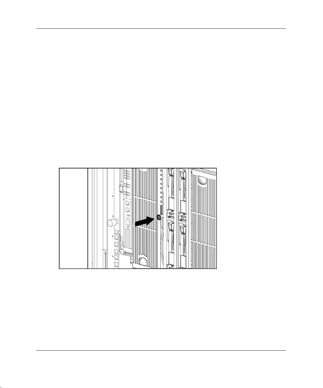
— Press the Power On/Standby button on the front of the server blade. Be sure
that the server blade is in standby mode by observing that the power LED is
amber.
Figure 1-1: Pressing the Power On/Standby button
HP ProLiant BL40p Server Blade Setup and Installation Guide 1-3
Page 16
Installing the Server Blade and Options
3. Remove the server blade from the server blade enclosure:
a. If the server blade is installed in either of the end bays and has a fibre
channel expansion board installed in a PCI-X slot, raise the locking handle at
the back of the server blade to unlock it from the enclosure.
CAUTION: To avoid damaging the equipment, be sure to unplug any fibre channel
expansion board cables from the rear of the server blade before removing the server
blade from the enclosure.
Figure 1-2: Unlocking the server blade from the
enclosure
1-4 HP ProLiant BL40p Server Blade Setup and Installation Guide
Page 17
Installing the Server Blade and Options
b. Press the release button to release the locking lever (1).
CAUTION: After you press the release button, the server blade is unlocked from
the enclosure. Use both hands to support the server blade when you remove it
from the rack.
c. Pull open the locking lever (2).
d. Grasp the lever and slide the server blade from the enclosure (3). Place a
hand under the server blade to support it as you remove it from the rack.
Figure 1-3: Removing the server blade from the server
blade enclosure
WARNING: The ProLiant BL40p server blade exceeds the recommended
25.86 kg
(57 lb)
HP ProLiant BL40p Server Blade Setup and Installation Guide 1-5
weight for one individual to handle safely.
To reduce the risk of personal injury or damage to the equipment,
observe local occupational health and safety requirements and
guidelines for manual material handling.
Page 18
Installing the Server Blade and Options
4. Place the server blade on a flat, level surface.
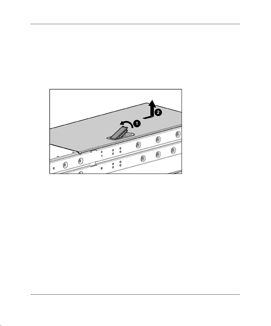
5. Remove the access panel:
a. Lift up on the hood latch handle until the access panel disengages from the
chassis (1).
b. Slide the access panel about 1.3 cm (1/2 inch) toward the rear of the unit and
lift the panel to remove it (2).
Figure 1-4: Removing the access panel
To replace the access panel, reverse step 5.
1-6 HP ProLiant BL40p Server Blade Setup and Installation Guide
Page 19
Installing the Server Blade and Options
Removing the System Board Tray Assembly
The system board tray assembly must be removed from the chassis for the
replacement of some components, but is not required for all preparation procedures.
Refer to the instructions for replacing a specific option to determine whether the
system board tray assembly must be removed. Refer to Figure 1-5 and Table 1-1 for
the locations of components that must be disconnected before removing the system
board tray assembly.
Figure 1-5: Component disconnection locations
Table 1-1: Component Disconnection Tasks
Item Component Task
1 PCI-X expansion boards Remove any installed PCI-X
expansion boards
2 Fan cable Disconnect from PCI-X
mezzanine board
continued
HP ProLiant BL40p Server Blade Setup and Installation Guide 1-7
Page 20

Installing the Server Blade and Options
Table 1-1: Component Disconnection Tasks continued
Item Component Task
3 DC power converter Disconnect from system board
4 RJ-45 cables Disconnect from PCI-X mezzanine board
5 SCSI I2C cable Disconnect from SCSI backplane board
6 SCSI backplane power cable Disconnect from SCSI backplane board
7 SCSI cables Disconnect from system board and SCSI
To remove the system board tray assembly:
IMPORTANT: All power must be removed from the server blade before performing these
procedures.
1. Remove the access panel. Refer to Figure 1-4.
2. Remove any installed PCI-X expansion boards.
and snap into the processor baffle
and snap into the processor baffle
backplane board
1-8 HP ProLiant BL40p Server Blade Setup and Installation Guide
Page 21
Installing the Server Blade and Options
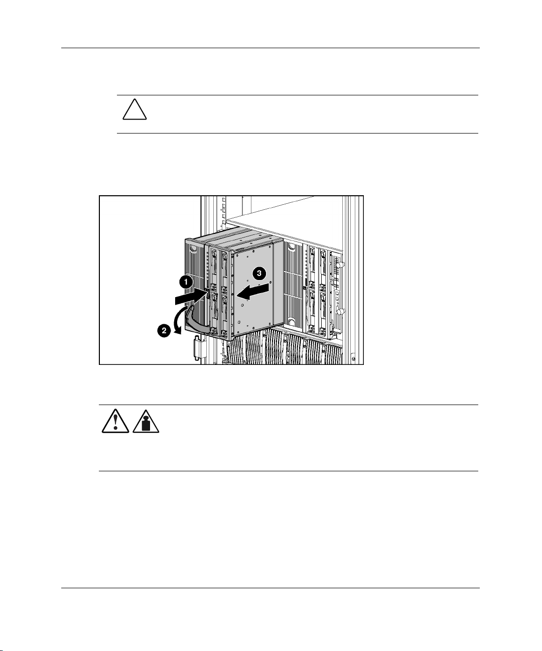
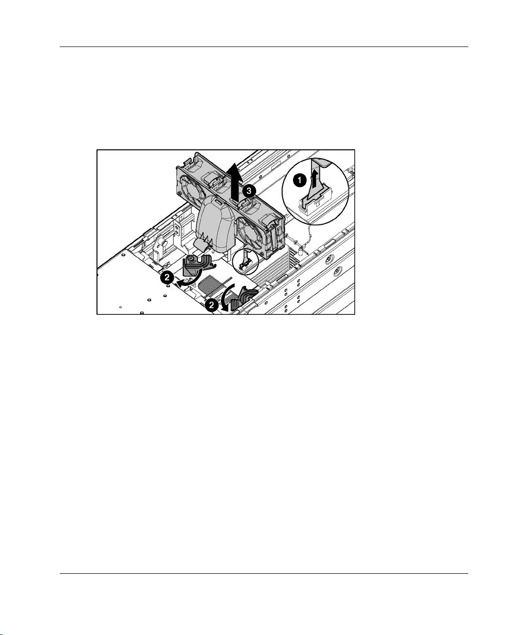
3. Remove the three-fan assembly:
a. Disconnect the fan cable from the PCI-X mezzanine board (1).
b. Pull out the fan clips located underneath the assembly (2).
c. Lift the assembly out of the chassis (3).
Figure 1-6: Removing the three-fan assembly
4. Remove the DC power converter from the system board. Refer to the label on the
DC power converter for details.
HP ProLiant BL40p Server Blade Setup and Installation Guide 1-9
Page 22
Installing the Server Blade and Options
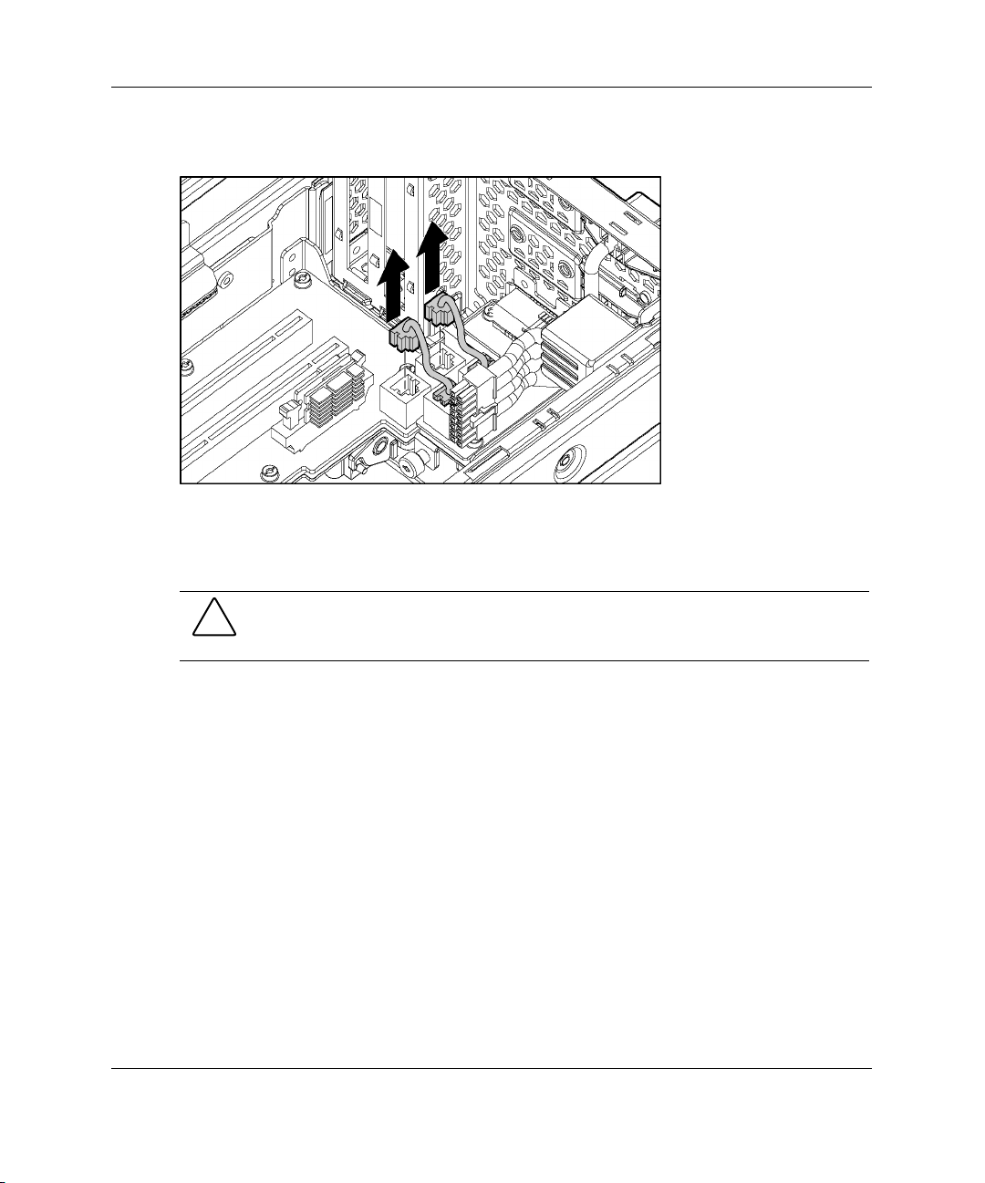
5. Disconnect the RJ-45 cables from the PCI-X mezzanine board.
Figure 1-7: Disconnecting RJ-45 cables
6. Disconnect the SCSI I2C cable from the SCSI backplane board, and snap the
cable into the processor baffle. Refer to Figure 1-8 and Figure 1-9.
CAUTION: The SCSI I2C cable must remain attached to the system board. To
avoid damaging the system board, remove only the end connected to the SCSI
backplane board.
1-10 HP ProLiant BL40p Server Blade Setup and Installation Guide
Page 23
Installing the Server Blade and Options
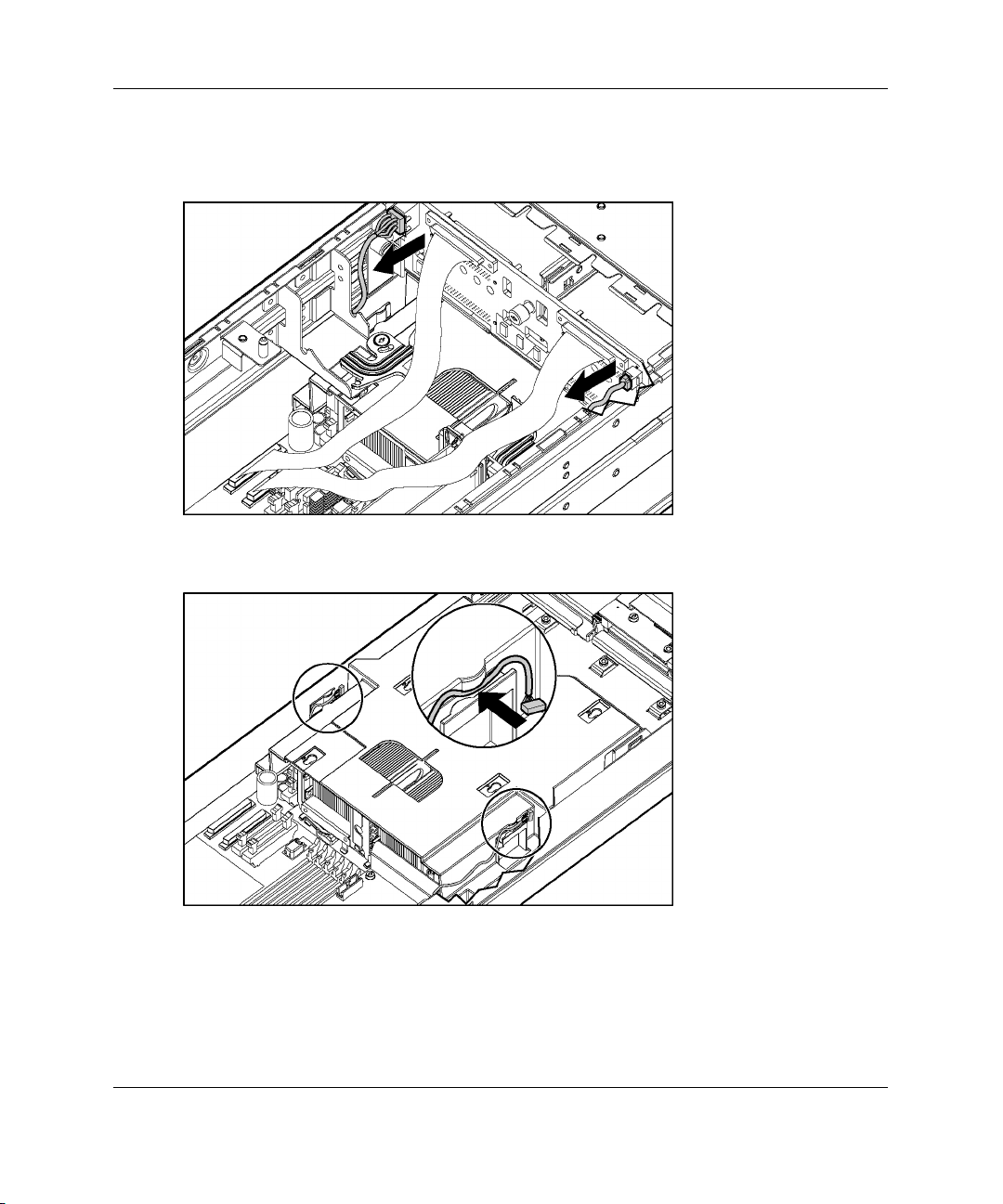
7. Disconnect the SCSI backplane power cable from the SCSI backplane board, and
snap the cable into the processor baffle. Refer to Figure 1-8 and Figure 1-9.
Figure 1-8: Disconnecting the SCSI I2C cable and the
SCSI backplane power cable
Figure 1-9: Attaching cables to the processor baffle
NOTE: The chassis has been removed from this illustration for clarity. At this point, the
system board tray assembly will still be inside the chassis.
HP ProLiant BL40p Server Blade Setup and Installation Guide 1-11
Page 24
Installing the Server Blade and Options
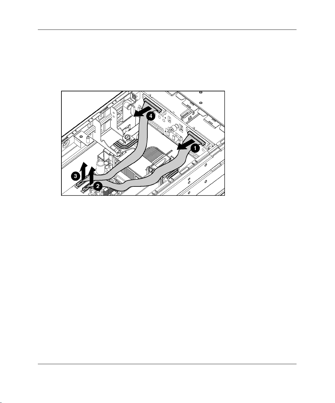
8. Disconnect both SCSI cables from the SCSI backplane board (1, 4) and from the
system board (2, 3).
NOTE: Numbers 3 and 4 in Figure 1-10 reference ports A (short cable). Numbers 1 and 2
reference ports B (long cable). Crossing the cables can result in incorrect data presentation.
Figure 1-10: Disconnecting the SCSI cables
1-12 HP ProLiant BL40p Server Blade Setup and Installation Guide
Page 25
Installing the Server Blade and Options
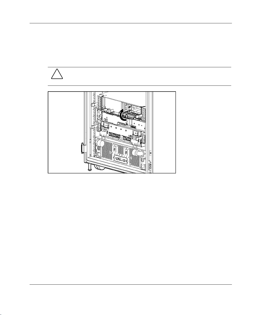
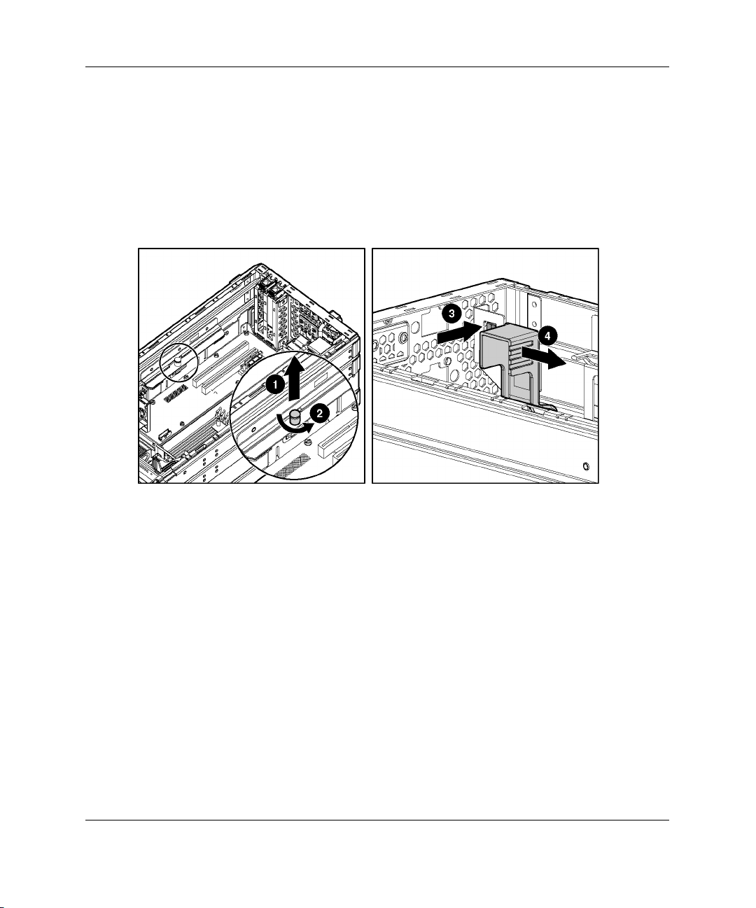
9. Lift the system board tray release latch (1) and turn it to unlock the system board
tray from the chassis (2).
10. Push the button to release the system board tray lever (3) and slowly slide it
towards the front of the server blade (4).
IMPORTANT: To avoid damaging the equipment, be sure to lift all cables away from the
system board before sliding the tray out.
Figure 1-11: Unlocking the system board tray
HP ProLiant BL40p Server Blade Setup and Installation Guide 1-13
Page 26
Installing the Server Blade and Options
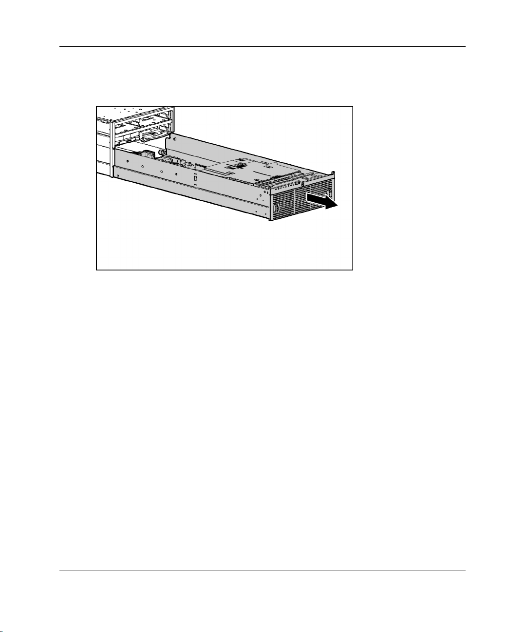
11. When the system board tray lever is completely forward, slide the system board
tray out of the chassis.
Figure 1-12: Removing the system board tray
To replace the system board, reverse steps 1 through 11.
1-14 HP ProLiant BL40p Server Blade Setup and Installation Guide
Page 27
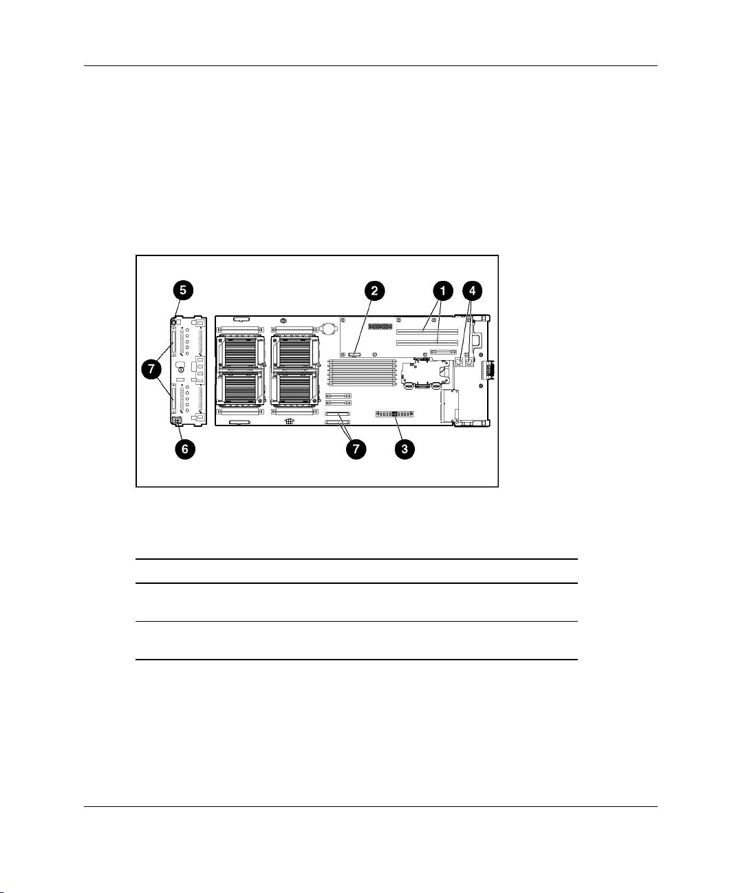
Identifying System Board Components
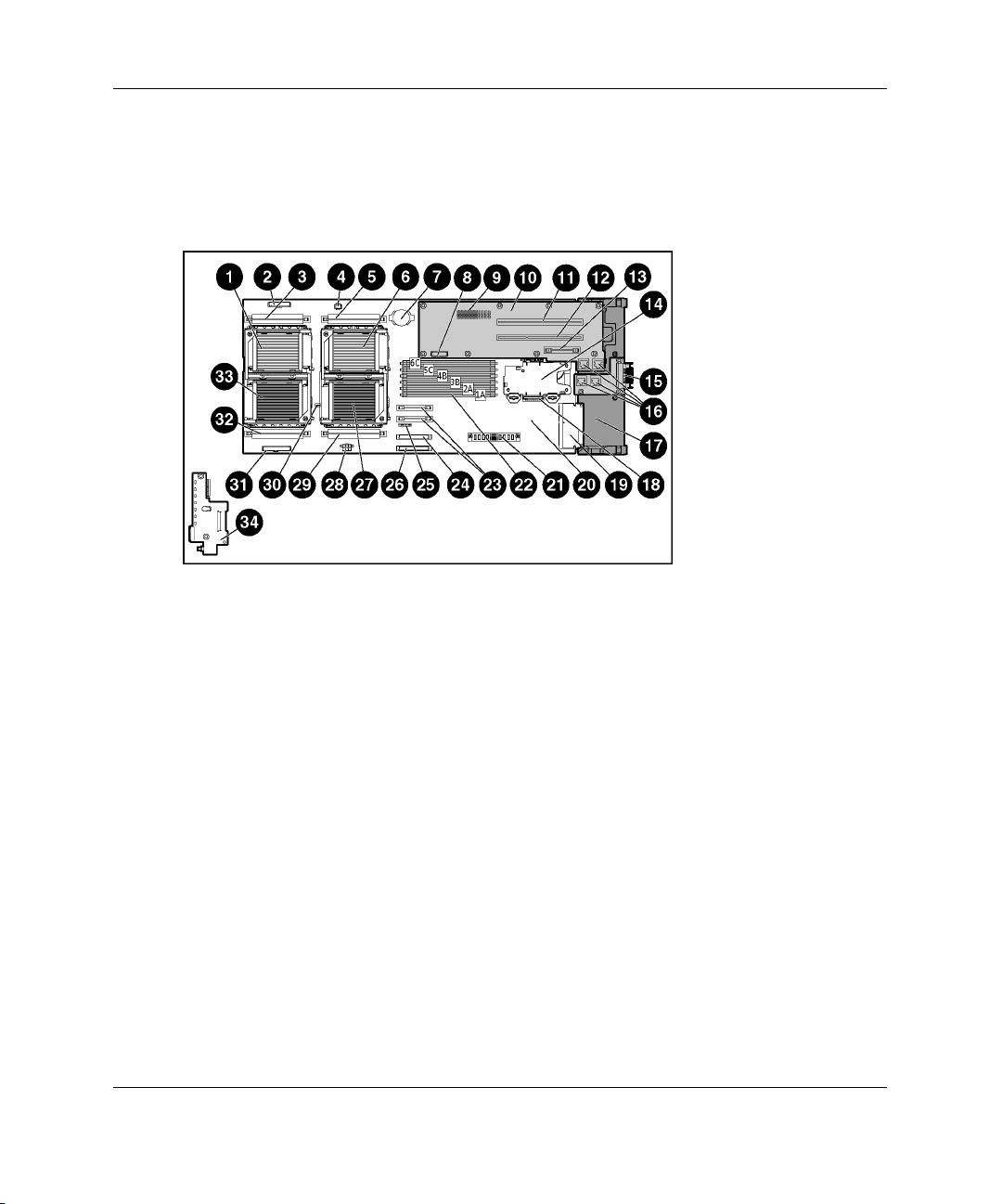
Use Figure 1-13 and Table 1-2 to identify the system board components and
connectors.
Figure 1-13: System board components and connectors
Installing the Server Blade and Options
HP ProLiant BL40p Server Blade Setup and Installation Guide 1-15
Page 28

Installing the Server Blade and Options
Table 1-2: System Board Components and Connectors
Item Description Item Description
1 Processor socket 3 18 I/O passthrough board connector
2 LED/power switch board connector 19 Smart Array 5i Plus memory module
3 PPM slot 3 20 System board
4 SCSI I2C cable connector 21 DC power converter connector
5 PPM slot 4 22 DIMM slots 1-6
6 Processor socket 4 23 System board power module
7 System battery 24 Channel B SCSI connector
8 SCSI backplane fan connector 25 System maintenance switch (SW3)
9 PCI-X mezzanine board connector 26 Channel A SCSI connector
10 PCI-X mezzanine board 27 Processor socket 1
11 64-bit/100 MHz PCI-X slot 2 28 SCSI power connector
12 64-bit/100 MHz PCI-X slot 1 29 PPM slot 1
13 PCI-X mezzanine power module 30 System ID switch (SW1)
14 Battery-Backed Write Cache Enabler 31 Processor fan connector
15 Ethernet passthrough board (attaches
to chassis)
16 RJ-45 connectors 33 Processor socket 2
17 NIC I/O board 34 LED/power switch board with I/O
32 PPM slot 2
pass-through
1-16 HP ProLiant BL40p Server Blade Setup and Installation Guide
Page 29

Memory
The server blade supports up to six 2-GB, PC2100, Registered, ECC DDR DIMMs.
The following sections explain DIMM slot locations, installation guidelines, and
installation procedures.
Online Spare Memory Configuration
With Online Spare Memory, you can configure primary server memory for up to
8 GB of ECC DDR memory and configure an additional 4 GB of online spare
memory. In this configuration, all six DIMM slots are populated with 2-GB
Registered ECC DDR DIMMs.
NOTE: Bank A refers to DIMM slots 1 and 2; bank B refers to DIMM slots 3 and 4; bank C
refers to DIMM slots 5 and 6.
In the online spare configuration, the ROM automatically configures the last
populated bank as the spare memory. If only banks A and B are populated, bank B is
the spare bank. If banks A, B, and C are populated, bank C is the spare bank. If
DIMMs in a non-spare bank exceed the limit for the single-bit correctable errors
threshold as defined by the Pre-Failure Warranty, the system copies the memory
contents of the failing bank to the spare bank. The system then deactivates the failing
bank and automatically switches over to the spare bank.
Installing the Server Blade and Options
For Online Spare Memory support, you must observe the following guidelines:
• • The ROM must be up to date.
DIMMs installed in a spare bank must be of equal or greater capacity than the
DIMMs installed in other banks.
For example, if bank A is populated with two 256-MB DIMMs and bank B is
populated with two 512-MB DIMMs, bank C must be populated with two
512-MB or greater DIMMs in order for online spare memory support to function
properly.
HP ProLiant BL40p Server Blade Setup and Installation Guide 1-17
Page 30

Installing the Server Blade and Options
After installing DIMMs, use ROM-Based Setup Utility (RBSU) to configure the
system for Online Spare Memory support:
1. Access RBSU by pressing the F9 key during power-up, when the prompt is
displayed in the lower right corner of the screen.
2. Select System Options.
3. Select Advanced Memory Protection.
4. Select Online Spare with Advanced ECC Support.
5. Press the Enter key.
6. Press the Esc key to exit the current menu or press the F10 key to exit RBSU.
DIMM Installation Guidelines
CAUTION: Use only HP supported DIMMs. DIMMs from other sources are known to
adversely affect data integrity.
You must observe the following guidelines when installing additional memory:
•
Install only PC2100, Registered, ECC DDR, 3.3-V, 72-bit wide DIMMs in the
server blade.
•
Always install memory in pairs of two identical DIMMs. DIMMs must be the
same speed.
IMPORTANT: Install identical DIMMs in slots 1A and 2A. You can install a second set of
identical DIMMs in slots 3B and 4B and a third set of identical DIMMs in slots 5C and 6C.
•
Install the DIMMs in the paired banks in sequential order, populating both slots
in a bank at the same time.
For Online Spare Memory support, you must also observe additional guidelines.
Refer to “Online Spare Memory Configuration” in this chapter.
1-18 HP ProLiant BL40p Server Blade Setup and Installation Guide
Page 31

Installing DIMMs
Before installing DIMMs, review “Online Spare Memory Configuration” in this
chapter.
WARNING: To reduce the risk of personal injury from hot surfaces, allow the
internal system components to cool before touching them.
CAUTION: Electrostatic discharge can damage electronic components. Properly
ground yourself before beginning any installation procedure. Refer to Appendix B,
“Electrostatic Discharge,” for more information.
To install a DIMM:
NOTE: The server blade ships with at least two DIMMs installed in DIMM slots 1A and 2A.
1. Remove the access panel. Refer to “Preparation Procedures” in this chapter.
2. Open the DIMM slot latches.
3. Align the key slot in the bottom edge of the DIMM with the tab in the DIMM
slot.
IMPORTANT: DIMMs do not seat if turned the wrong way.
Installing the Server Blade and Options
HP ProLiant BL40p Server Blade Setup and Installation Guide 1-19
Page 32

Installing the Server Blade and Options
4. Insert the DIMM into the DIMM slot (1).
5. Press down firmly. When the DIMM seats fully in the slot, the latches close (2).
Figure 1-14: Installing a DIMM
6. Reinstall the access panel. Refer to “Preparation Procedures” in this chapter.
1-20 HP ProLiant BL40p Server Blade Setup and Installation Guide
Page 33

Processors
The ProLiant BL40p server blade has the capability of up to four Intel® Xeon™
processors. To remove a processor:
1. Power down the server blade and remove it from the server blade enclosure.
Refer to “Preparation Procedures” in this chapter.
2. Remove the access panel and the system board tray. Refer to “Preparation
Procedures” in this chapter.
3. Unsnap the SCSI I2C cable and SCSI backplane power cable from the processor
baffle.
4. Slide the processor baffle back, and lift it off of the processor assemblies. Push
the cables through the access holes in the processor baffle, but leave them
attached to the system board as the processor baffle is removed.
CAUTION: To avoid damaging the system board, use caution when removing the
processor baffle. The SCSI I2C cable must remain attached to the system board at
this point.
Installing the Server Blade and Options
Figure 1-15: Removing the processor baffle
HP ProLiant BL40p Server Blade Setup and Installation Guide 1-21
Page 34

Installing the Server Blade and Options
5. Lift the blue processor cage lever to release the processor cage (1).
6. Raise the processor cage away from the processor assembly (2).
Figure 1-16: Removing the processor cage
1-22 HP ProLiant BL40p Server Blade Setup and Installation Guide
Page 35

Installing the Server Blade and Options
7. Lift the processor-locking lever to release processor assembly (1).
8. Lift the processor assembly away from the processor socket (2).
Figure 1-17: Removing a processor
CAUTION: To avoid damage to the processors and processor sockets, be sure to:
• Completely open the processor-locking lever when installing a processor
assembly.
• Completely close the processor-locking lever before lowering the processor
cage.
HP ProLiant BL40p Server Blade Setup and Installation Guide 1-23
Page 36

Installing the Server Blade and Options
To install a processor, reverse steps 1 through 7. When lowering the processor
assembly, be sure to correctly align the pins (1) before closing the processor-locking
lever (2).
CAUTION: When installing three processors, they must occupy sockets 1, 2, and 4.
Figure 1-18: Aligning the processor pins and installing
the processor
CAUTION: Do not separate the processor from the heatsink. They ship as one
assembly and separating them will damage the assembly.
1-24 HP ProLiant BL40p Server Blade Setup and Installation Guide
Page 37

Installing the Server Blade and Options
Battery-Backed Write Cache Enabler
The Smart Array 5i Battery-Backed Write Cache Enabler, also known as the battery
module, provides transportable data protection, increases overall controller
performance, and maintains any cached data for up to 72 hours without external
power. It provides the system with a means for storing and saving data in the event of
an unexpected system shutdown. The NiMH batteries in the battery module are
continuously recharged through a trickle-charging process whenever the system
power is on. Under normal operating conditions, the battery module lasts for 3 years
before replacement is necessary.
To install the battery module:
1. Power down the server blade and remove it from the server blade enclosure.
Refer to the “Preparation Procedures” section in this chapter.
2. Remove the access panel. Refer to “Preparation Procedures” in this chapter.
3. Install the battery module onto the standoffs on the system board. Be sure the
battery module seats firmly, and turn the standoffs to secure.
NOTE: If you purchased the Battery-Backed Write Cache Enabler as an option, you need to
attach the plastic casing separately.
Figure 1-19: Installing the Battery-Backed Write Cache
HP ProLiant BL40p Server Blade Setup and Installation Guide 1-25
Page 38

Installing the Server Blade and Options
4. Connect the cable from the battery module to the Smart Array 5i Plus memory
module.
Figure 1-20: Cabling the Battery-Backed Write Cache
Enabler
5. Reinstall the system board and the access panel. Refer to “Preparation
Procedures” in this chapter.
NOTE: Insight Manager 7 will indicate a low charge until the battery module is fully charged
for 24 to 48 hours.
Hot-Plug SCSI Hard Drives and Blanks
The following section explains removal and installation of hard drive blanks and
hot-plug SCSI hard drives.
Removing Hard Drive Blanks
The server blade ships standard with four hard drive blanks. Before installing a
hot-plug SCSI hard drive, you must remove a blank.
1-26 HP ProLiant BL40p Server Blade Setup and Installation Guide
Page 39

Installing the Server Blade and Options
CAUTION: Always populate drive bays with either a hard drive or blank. Proper
airflow can only be maintained when the bays are populated. Unpopulated drive bays
can lead to improper cooling and thermal damage.
To remove a hard drive blank:
1. Press and hold the release button (1).
2. Pull the blank out of the drive bay (2).
Figure 1-21: Removing a hard drive blank
NOTE: Store the hard drive blank for future use.
To install a hard drive blank, simply align the blank with the empty bay and slide the
blank into the bay until the locking button engages.
HP ProLiant BL40p Server Blade Setup and Installation Guide 1-27
Page 40

Installing the Server Blade and Options
SCSI ID Numbers
The server blade hot-plug SCSI hard drives have unique SCSI IDs that the system
automatically sets. Figure 1-22 shows SCSI IDs for the server blade.
IMPORTANT: Always populate hard drive bays starting with SCSI ID 0 (items 3 and 4 in
Figure 1-22).
Figure 1-22: SCSI ID numbers
Table 1-3: Server Blade SCSI IDs
Item Description Bus
1 SCSI ID 1 B
2 SCSI ID 1 A
3 SCSI ID 0 B
4 SCSI ID 0 A
1-28 HP ProLiant BL40p Server Blade Setup and Installation Guide
Page 41

Installing Hot-Plug SCSI Hard Drives
To install hot-plug SCSI hard drives:
1. Remove the existing hard drive blank or SCSI hard drive from the bay:
— If a hard drive blank is installed in the bay, refer to “Removing Hard Drive
Blanks” in this chapter.
— If a SCSI hard drive is already installed in the bay, refer to “Removing
Hot-Plug SCSI Hard Drives” in this chapter.
2. Insert the hot-plug SCSI hard drive (1). Be sure the drive seats firmly into the
connector on the SCSI backplane.
3. Close the ejector lever (2).
Installing the Server Blade and Options
Figure 1-23: Installing a hot-plug SCSI hard drive
4. If you replaced a hard drive, restore the server blade data from the backup.
5. Use the hot-plug SCSI hard drive LEDs to identify the status of the installed
drive. For more information about these LEDs, refer to the “Hot-Plug SCSI Hard
Drive LEDs” section in Appendix E, “LEDs and Switches.”
6. Resume normal server blade operations.
HP ProLiant BL40p Server Blade Setup and Installation Guide 1-29
Page 42

Installing the Server Blade and Options
Removing Hot-Plug SCSI Hard Drives
To remove hot-plug SCSI hard drives:
1. Back up all server blade data on the hard drive.
CAUTION: Before removing a hot-plug SCSI hard drive, use the LEDs to
determine the status of the drive. Refer to the “Hot-Plug SCSI Hard Drive LEDs”
section in Appendix E, “LEDs and Switches.”
CAUTION: If you are replacing a drive that is part of an array, refer to the
“Hot-Plug SCSI Hard Drive Replacement Guidelines” section in the HP ProLiant
Servers Troubleshooting Guide.
2. Press the port-colored ejector lever release button (1).
NOTE: Port-colored items indicate hot-plug components.
3. Pull the ejector lever open (2).
4. Remove the hard drive (3).
Figure 1-24: Removing a hot-plug SCSI hard drive
1-30 HP ProLiant BL40p Server Blade Setup and Installation Guide
Page 43

Installing Expansion Boards
The ProLiant BL40p server blade delivers fibre channel support for SAN
implementations and clustering capabilities. The server blade has two PCI-X slots for
redundant SAN connectivity and is optimized for HP StorageWorks. In addition, the
server blade is also compatible with certain third-party SAN products. Refer to the
contents included with the expansion board for cabling and SAN configuration
instructions. To install an expansion board into a PCI-X slot:
1. Remove the access panel. Refer to “Preparation Procedures” in this chapter.
2. Remove the expansion board blank corresponding to the PCI-X slot you are
populating by pressing down on the release lever (1), then pulling up (2).
3. Slide the expansion board blank out of the slot (3).
Installing the Server Blade and Options
Figure 1-25: Removing expansion board blanks
HP ProLiant BL40p Server Blade Setup and Installation Guide 1-31
Page 44

Installing the Server Blade and Options
4. Open the alignment guide (1).
5. Install the expansion board into the PCI-X slot (2).
6. Close the alignment guide (3).
7. Close the release lever (4).
Figure 1-26: Installing an expansion board
8. Repeat steps 2 through 7 for PCI-X slot 2 if installing an additional expansion
board.
9. Reinstall the access panel.
10. Install the server blade into the enclosure. Refer to “Installing a Server Blade” in
this chapter.
11. Cable the expansion board as necessary. Refer to the documentation included
with the expansion board for instructions.
1-32 HP ProLiant BL40p Server Blade Setup and Installation Guide
Page 45

Server Blades
Before installing server blades for the first time, define your hardware configuration
and server blade deployment process. Refer to Chapter 2, “Configuring and
Deploying Server Blades.”
WARNING: The ProLiant BL40p server blade exceeds the recommended
25.86 kg
(57 lb)
weight for one individual to handle safely.
To reduce the risk of personal injury or damage to the equipment,
observe local occupational health and safety requirements and
guidelines for manual material handling.
Installing a Server Blade
CAUTION: Always populate the server blade enclosure bays with either a server
blade or server blade blank. Proper airflow can only be maintained when the bays
are populated. Unpopulated bays can lead to improper cooling and thermal damage.
To install a server blade:
Installing the Server Blade and Options
HP ProLiant BL40p Server Blade Setup and Installation Guide 1-33
Page 46

Installing the Server Blade and Options
1. Four server blade blanks must be removed before installing a BL40p server blade
into the enclosure. To remove a server blade blank:
a. Press the release buttons (1).
b. Slide the server blade blank out of the bay (2).
Figure 1-27: Removing a server blade blank
NOTE: Store the server blade blank for future use.
2. Repeat step 1 to remove the three other server blade blanks from adjacent bays.
3. Align the keyed end of the server blade with the guide at the end of a bay on the
server blade enclosure.
IMPORTANT: The server blade is keyed to fit only one way in the bay. If the server blade
does not slide easily into the bay, be sure that the server blade is oriented properly.
1-34 HP ProLiant BL40p Server Blade Setup and Installation Guide
Page 47

Installing the Server Blade and Options
4. If the server blade is not populating bays 1 through 4 (farthest left) or bays 5
through 8 (farthest right):
a. Use a Torx T-15 screwdriver to remove the 3 screws from the locking
handle (1).
b. Remove the locking handle from the back of the server blade (2).
NOTE: The locking handle keeps the server blade locked to the enclosure when it is installed
in either of the end bays. If you are installing the server blade in the middle of the enclosure,
the locking handle will not fit properly into the enclosure.
Figure 1-28: Removing the locking handle from the
server blade
HP ProLiant BL40p Server Blade Setup and Installation Guide 1-35
Page 48

Installing the Server Blade and Options
5. Install the server blade into the bay. Slide the server blade fully into the bay (1).
6. Close the ejector lever (2).
Figure 1-29: Installing a server blade
7. If installing the server blade into either of the end bays, and if the server blade
has PCI-X boards installed, close the locking handle on the back of the server
blade to secure it to the server blade enclosure.
Figure 1-30: Closing the locking handle
1-36 HP ProLiant BL40p Server Blade Setup and Installation Guide
Page 49

Powering Up the Server Blade
To install a server blade in the server blade enclosure, refer to “Installing a Server
Blade” in this chapter.
Server blades are set to power up automatically. If you changed this setting, use one
of the following methods to power up the server blade:
•
Power On/Standby button
— A momentary press initiates a power-up request. The system detects if power
is available to power on the server blade.
— A long press, 5 or more seconds, initiates a power-up override. The system is
forced to power up the server blade without detecting available power.
CAUTION: Always observe iLO alerts before initiating a power-up override to
prevent a hot-plug power supply fault and possible loss of system power.
NOTE: You may choose to perform a power-up override to power up a server blade and
to override the power-up request function when the management modules are not in use
and when you know that sufficient power is available.
Installing the Server Blade and Options
• Virtual power button features through the iLO remote console
— A Press and Hold selection initiates a power-off request. The system is
forced to power off if the operating system does not respond to a momentary
press.
— A Power Cycle System On, After Off selection simulates turning the server
blade off and back on with one button press.
For more information about iLO, refer to Chapter 2, “Configuring and Deploying
Server Blades.”
HP ProLiant BL40p Server Blade Setup and Installation Guide 1-37
Page 50

Configuring and Deploying Server Blades
This chapter contains information about server blade deployment methods, hardware
configuration, and the software to accomplish these tasks.
Configuration and Deployment Overview
Three primary deployment methods are supported:
•
Remote deployment using ProLiant Essentials Rapid Deployment Pack (RDP)
•
Remote deployment using virtual devices through iLO
•
Deployment using local devices with the I/O cable (depending on the server
model)
Remote Deployment using RDP
2
The RDP software is the preferred method for rapid, high-volume server blade
deployments. The RDP software integrates two powerful products: Altiris eXpress
Deployment Solution and the ProLiant Integration Module.
The Altiris eXpress Deployment Server Console has an intuitive graphical user
interface that provides simplified drag-and-drop server deployment using either
imaging or scripting. The console also has advanced features for blade servers. The
user can view blade servers in a physical tree view according to their
Rack\Enclosure\Bay settings. The Deployment Server can detect when a blade is
ripped out and replaced with a new blade. The user can configure the Deployment
Server to automatically replay all deployment jobs on the new blade.
HP ProLiant BL40p Server Blade Setup and Installation Guide 2-1
Page 51

Configuring and Deploying Server Blades
If you purchased RDP with the blade enclosure, follow the instructions on the Quick
Start Guide, included in the kit, to register and install the software.
For product information and the latest RDP documentation, go to
www.hp.com/servers/rdp
Remote Deployment using Virtual Devices through iLO
The server blade should be connected to a network before beginning the deployment
process. Connect to the server blade with one of the following methods:
• • Through an existing network (in the rack)
This method requires you to install the server blade in its enclosure and assign it
an IP address (manually or using DHCP).
Through an existing network (out of the rack, with the diagnostic station)
This method enables you to configure a server blade out of the rack by powering
the blade with the diagnostic station and connecting to an existing network
through a hub. The IP address is assigned by a DHCP server on a network.
Integrated Lights-Out (iLO) can be a helpful debugging tool in the configuration and
deployment process. HP recommends using iLO to follow the deployment process.
Refer to “Integrated Lights-Out Management” in this chapter for information about
these additional methods.
iLO Virtual CD-ROM Deployment
To perform a boot CD deployment:
1. Do one of the following:
— Insert the boot CD into the client PC from which you are running the iLO
Remote Console.
— Use iLO Advanced to create an image file of the boot CD.
— Copy the image of the boot CD to a location on the network or the client PC
hard drive.
2-2 HP ProLiant BL40p Server Blade Setup and Installation Guide
Page 52

2. Remotely access the server blade through iLO Advanced. Refer to the HP
Integrated Lights-Out User Guide.
3. Click the Virtual Devices tab.
4. Select Virtual Media.
5. Use the Virtual Media applet to select the local CD or image file and connect the
Virtual CD to the server blade.
6. Use the iLO Virtual Power Button feature to reboot the server blade.
After the server blade boots, follow the normal network installation procedure for an
operating system.
iLO Virtual Floppy Deployment
To perform a boot diskette deployment:
IMPORTANT: To deploy a server blade without the RDP, you must create a bootable
diskette or an image of a bootable diskette. Refer to ”Creating the Boot Diskette.”
1. Do one of the following:
Configuring and Deploying Server Blades
— Insert the boot diskette into the client PC from which you are running the
iLO Remote Console.
— Use iLO to create an image file of the boot diskette.
— Copy the image of the boot diskette to a location on the network or the client
PC hard drive.
2. Remotely access the server blade through the iLO. Refer to “Integrated LightsOut Management” in this chapter.
3. Select the Virtual Devices tab.
4. Select Virtual Media.
5. Use the Virtual Media applet to select the local diskette or image file and connect
the Virtual Disk to the server blade.
6. Use the iLO Virtual Power Button feature to reboot the server blade.
HP ProLiant BL40p Server Blade Setup and Installation Guide 2-3
Page 53

Configuring and Deploying Server Blades
After the server blade boots, follow the normal network installation procedure for
your operating system.
Deployment using Local Devices with the I/O Cable
Use either the diagnostic cable or the I/O cable to perform some server blade
configuration and diagnostic procedures. Depending on the model, the server blade
will have either a diagnostic port or an I/O port. The I/O port only accepts the I/O
cable and the diagnostic port only accepts the diagnostic cable. If the server blade has
an I/O icon next to the port on the front of the server blade, use the I/O cable. If the
port has no icon, use the diagnostic cable. Refer to Figure 2-1 to identify the I/O icon.
Figure 2-1: I/O cable with large view of the I/O icon
Identifying Diagnostic and I/O Cable Connectors
Figure 2-2 and Table 2-1 identify diagnostic cable and I/O cable connectors.
2-4 HP ProLiant BL40p Server Blade Setup and Installation Guide
Page 54

Configuring and Deploying Server Blades
Figure 2-2: Connectors
Table 2-1: Diagnostic and I/O cable connectors
Item Description
1 Server blade connector
2 iLO RJ-45 (10/100 Ethernet) connector
3 Kernel debug connector**
4 Video connector
5 USB connector (2)
6 Kernel debug connector**
7 iLO RJ-45 (10/100 Ethernet) connector
8 Server blade connector
*The I/O cable is labeled with the I/O icon. The diagnostic cable
has no label.
**The kernel debug connector does not function as a serial port.
HP ProLiant BL40p Server Blade Setup and Installation Guide 2-5
Diagnostic cable
I/O cable*
Page 55

Configuring and Deploying Server Blades
Connecting the Diagnostic Cable or the I/O Cable
To connect to iLO using either the diagnostic cable or the I/O cable, you must have
the following:
• A client PC with a 10/100 Ethernet RJ-45 connector
• A network cable with RJ-45 connectors
To connect to iLO:
IMPORTANT: Do not connect the diagnostic cable or the I/O cable to a hub when using an IP
address to connect to iLO. All server blades have the same IP address through the diagnostic
or I/O port. Multiple server blades on a hub make the server blades indistinguishable on the
network.
NOTE: Connecting the diagnostic cable to the diagnostic port or the I/O cable to the I/O port
automatically disables the iLO connection on the rear of the server blade when the connection
to the front port is active.
1. Connect one end of the RJ-45 network cable to the diagnostic cable (1) or the I/O
cable, depending on the server blade.
2. Connect the other end of the network cable to the 10/100 Ethernet RJ-45
connector on the client PC (2).
Figure 2-3: Connecting an RJ-45 network cable
2-6 HP ProLiant BL40p Server Blade Setup and Installation Guide
Page 56

Configuring and Deploying Server Blades
3. Connect the server blade connector to the server blade.
CAUTION: Disconnect the diagnostic cable or the I/O cable from the port when not
in use. The port and connector do not provide permanent connections.
CAUTION: Rear iLO connector performance degrades when the I/O cable or the
diagnostic cable is in use, even when the iLO connector on the cable is not in use.
CAUTION: Always match the I/O cable labeled with the I/O icon to the I/O port also
labeled with the I/O icon. The diagnostic cable and port have no labels. Mismatched
cables prevent proper connection and can cause damage.
Figure 2-4: Connecting either the diagnostic cable (1) or
the I/O cable (2) to the server blade
CAUTION: For the diagnostic cable, the locking button is located on the top of the
server blade connector.
For the I/O cable, the locking buttons are located on the sides of the server blade
connector.
Always be sure to squeeze the locking button on the diagnostic cable before
disconnecting the diagnostic cable from the diagnostic port. Failure to do so can
result in damage to the equipment.
HP ProLiant BL40p Server Blade Setup and Installation Guide 2-7
Page 57

Configuring and Deploying Server Blades
Connecting Directly to a Server Blade using Video and USB Devices
To connect directly to the server blade, use the I/O cable and any combination of the
following USB devices:
•
Monitor
•
USB Hub
•
USB Keyboard
•
USB Mouse
•
USB CD-ROM
•
USB Diskette Drive
The devices can be connected to the I/O cable in various configurations. Two of the
possible configurations are detailed in the following:
Directly Accessing a Configured Server Blade
Use the following setup to access a configured server blade:
CAUTION: Rear iLO connector performance degrades when the I/O cable or the
diagnostic cable is in use, even when the iLO connector on the cable is not in use.
NOTE: For this setup, a hub is not necessary to connect directly to the blade. If you need
additional connections, use the second setup.
2-8 HP ProLiant BL40p Server Blade Setup and Installation Guide
Page 58

Configuring and Deploying Server Blades
1. Connect the I/O cable to the server blade (1).
2. Connect the video connector to a monitor (2).
3. Connect a USB mouse to the USB connector (3).
4. Connect a USB keyboard to the USB connector (4).
Figure 2-5: Directly accessing a configured server blade
Directly Accessing a Server Blade to Configure a Server Blade or Load Software
Updates
Use the following setup to configure a server blade using a SmartStart CD or to load
software updates or patches using the CD-ROM:
CAUTION: Rear iLO connector performance degrades when the I/O cable or the
diagnostic cable is in use, even when the iLO connector on the cable is not in use.
HP ProLiant BL40p Server Blade Setup and Installation Guide 2-9
Page 59

Configuring and Deploying Server Blades
1. Connect the I/O cable to the server blade (1).
2. Connect a monitor to the video connector (2).
3. Connect a USB hub to a USB connector (3).
4. Connect the following to the USB hub:
a. USB CD-ROM (4) and/or a USB diskette drive
b. USB keyboard (5)
c. USB mouse (6)
NOTE: HP recommends the use of a USB hub when connecting a USB diskette drive and/or
USB CD-ROM drive to the server blade. This will provide more available connections.
Figure 2-6: Directly connecting to the server blade
using a USB hub
USB CD-ROM Deployment
CD-ROM deployment involves a bootable CD that executes a script that configures
the hardware and installs the operating system.
2-10 HP ProLiant BL40p Server Blade Setup and Installation Guide
Page 60

Configuring and Deploying Server Blades
SmartStart simplifies the deployment process and facilitates loading the operating
system. However, SmartStart does not prevent you from loading the operating system
and drivers manually. For more information on SmartStart, refer to the HP website:
www.hp.com/servers/smartstart
To perform a boot CD deployment:
1. Connect a USB CD-ROM, USB mouse, USB keyboard, and a monitor to the
server blade using the I/O cable. Install a USB hub on the I/O cable to provide
additional USB connections.
2. Insert the Smart Start CD or the operating system CD in the CD-ROM.
3. Reboot the server blade.
4. After the server blade boots, follow the normal installation procedure for an
operating system.
After the operating system is configured, the server blade can access the network to
locate the scripts and files necessary for deployment. The server blade should be
connected to a network before beginning the deployment process. Connect to the
server blade with one of the following methods:
• • Through an existing network (in the rack)
This method requires you to install the server blade in its enclosure and assign it
an IP address (manually or using DHCP).
Through an existing network (out of the rack, with the diagnostic station)
This method enables you to configure a server blade out of the rack by powering
the blade with the diagnostic station and connecting to an existing network
through a hub. The IP address is assigned by a DHCP server on a network.
USB Diskette Drive Deployment
Diskette Image Deployment involves creating a DOS-based network-enabled boot
diskette that executes a script that configures the hardware and installs the operating
system. Server blades have two mechanisms for using the diskette: iLO Virtual
Floppy and PXE.
HP ProLiant BL40p Server Blade Setup and Installation Guide 2-11
Page 61

Configuring and Deploying Server Blades
IMPORTANT: To deploy a server blade without the RDP, you must create a bootable
diskette or image of a bootable diskette. Refer to ”Creating the Boot Diskette.”
To perform a boot diskette deployment:
1. Connect a USB diskette drive, USB mouse, USB keyboard, and a monitor to the
server blade using the I/O cable. Install a USB hub on the I/O cable to provide
additional USB connections.
2. Insert the boot diskette into the USB diskette drive.
3. Reboot the server blade.
4. After the server blade boots, follow the normal installation procedure for an
operating system.
The diskette gets the server blade on the network where it can access the scripts and
files necessary for deployment. This implies a deployment infrastructure that may
include an administrator workstation, PXE server, Windows® file share, or a Linux
file share.
The server blade must be connected to a network before beginning the deployment
process. Connect to the server blade with one of the following methods:
• • Through an existing network (in the rack)
This method requires you to install the server blade in its enclosure and assign it
an IP address (manually or using DHCP).
Through an existing network (out of the rack, with the diagnostic station)
This method enables you to configure a server blade out of the rack by powering
the blade with the diagnostic station and connecting to an existing network
through a hub. The IP address is assigned by a DHCP server on an network.
Other methods are available for connecting to the ProLiant BL40p server blade, but
they do not provide the network accessibility required to deploy the server. Refer to
“Integrated Lights-Out Management” in this chapter for information about these
additional methods.
2-12 HP ProLiant BL40p Server Blade Setup and Installation Guide
Page 62

Configuring and Deploying Server Blades
NOTE: For more information about these hardware and cabling configurations, refer to the HP
ProLiant BL p-Class System Hardware Configuration and Installation Poster and the
documentation that ships with the diagnostic station.
Creating the Boot Diskette
The SmartStart Scripting Toolkit provides the tools and information for creating a
diskette that will configure the hardware and install the operating system.
For details, download the latest version of the “SmartStart Scripting Toolkit” from
www.hp.com/servers/sstoolkit
and refer to the SmartStart Scripting Toolkit User Guide.
It is also possible to configure the hardware manually using RBSU through the iLO
remote console. With this method, the diskette would be more generic and would
integrate into the existing network OS installation process. Refer to the “Integrated
Lights-Out Management” section in this chapter.
For the most current information about operating system support on server blades,
refer to the operating system support matrix available at:
www.hp.com/products/servers/platforms
then navigate to the OS support for ProLiant BL p-Class server blades.
IMPORTANT: The ProLiant BL40p server blade has the ability to connect to a SAN using
PCI-X expansion boards. You can preconfigure the SAN HBA driver Smart Components in the
ProLiant Support Pack. Refer to the HP ProLiant Support Pack and Deployment Utility User
Guide or “SAN Support” in this chapter for more information.
USB Diskette Drive Deployment using PXE
PXE enables server blades to load an image over the network from a PXE server then
execute it in memory. The first NIC on the server blade is the default PXE boot NIC,
but any of the other NICs can be configured to boot PXE. Refer to “PXE
Deployment” in this chapter for more information.
HP ProLiant BL40p Server Blade Setup and Installation Guide 2-13
Page 63

Configuring and Deploying Server Blades
A number of third-party PXE deployment tools are available for Windows and Linux.
For additional information refer to
ftp.compaq.com/pub/products/servers/management/pxe_wp.pdf
SAN Support
The ProLiant BL40p server blade delivers fibre channel support for SAN
implementations and clustering capabilities. The ProLiant BL40p server blade has
two PCI-X expansion slots for redundant SAN connectivity and is optimized for HP
StorageWorks. In addition, the server blade is also compatible with certain thirdparty SAN products.
For SAN configuration information for the server blade, consult the QuickSpecs
located on the ProLiant BL40p 2 product page on
www.hp.com
Or the SAN Design Reference Guide located at
www.compaq.com/products/storageworks/san/documentation.html
Software and Utilities
This section provides information about the following utilities and support tools:
• Integrated Lights-Out (iLO) Management
• Redundant ROM Support
• ROMPaq Utility
• ROM-Based Setup Utility (RBSU)
• Option ROM Configuration for Arrays (ORCA) Utility
• Network-based PXE Deployment
• SmartStart Scripting Toolkit
• Insight Manager 7
• Diagnostics Utility
2-14 HP ProLiant BL40p Server Blade Setup and Installation Guide
Page 64

Configuring and Deploying Server Blades
• Automatic Server Recovery (ASR-2)
•
Integrated Management Log (IML)
HP also offers the following software components:
•
Health and Wellness Driver and IML Viewer
•
iLO Management Interface Driver
•
Rack Infrastructure Interface Service
•
Management Agents
For Microsoft® Windows operating system users, these items are included in the
HP ProLiant Support Pack for Microsoft Windows, available from the ProLiant BL
p-Class system product page on
www.hp.com/support/files
Linux operating system users must install these items manually. For information
about downloading these components, refer to
www.hp.com/support
For information on how to use these components with a Linux operating system,
refer to
http://h18000.www1.hp.com/products/servers/linux/documentation.html#howtos
Integrated Lights-Out Management
The iLO subsystem includes an intelligent microprocessor, secure memory, and a
dedicated network interface. This design makes iLO independent of the host server
blade and its operating system. The iLO subsystem provides remote access to any
authorized network client, sends alerts, and provides other server blade management
functions.
Using a supported Web browser, you can:
•
Remotely access the console of the host server blade, including all text mode and
graphics mode screens with full keyboard and mouse controls.
•
Remotely power up, power down, or reboot the host server blade.
HP ProLiant BL40p Server Blade Setup and Installation Guide 2-15
Page 65

Configuring and Deploying Server Blades
• Remotely boot a host server blade to a virtual diskette image to perform a ROM
upgrade or to install an operating system.
•
Send alerts from iLO regardless of the state of the host server blade.
•
Access advanced troubleshooting features provided by iLO.
•
Launch a Web browser, use Simple Network Management Protocol (SNMP)
alerting, and diagnose the server blade using Insight Manager 7.
The server blade must be properly cabled for iLO connectivity. Connect to the server
blade with one of the following methods:
•
Through an existing network (in the rack)
This method requires you to install the server blade in its enclosure and assign it
an IP address (manually or using DHCP).
•
Through the server blade diagnostic port
— In the rack
This method requires you to connect the diagnostic cable to the diagnostic
port and a client PC. Using the static IP address listed on the diagnostic cable
label and the initial access information on the front of the server blade, you
can access the server blade with the iLO Remote Console. For diagnostic
cabling instructions, refer to “Using the Diagnostic Cable” in Chapter 1,
“Installing the Server Blade and Options.”
— Out of the rack, with the diagnostic station
This method requires you to power the server blade with the optional
diagnostic station and connect to an external computer using the static IP
address and the diagnostic cable. For cabling instructions, refer to the
documentation that ships with the diagnostic station or to the Documentation
CD.
•
Through the server blade rear panel connectors (out of the rack, with the
diagnostic station)
This method enables you to configure a server blade out of the rack by powering
the blade with the diagnostic station and connecting to an existing network
through a hub. The IP address is assigned by a DHCP server on the network.
2-16 HP ProLiant BL40p Server Blade Setup and Installation Guide
Page 66

iLO ROM-Based Setup Utility
The iLO ROM-Based Setup Utility (iLO RBSU) is the recommended method to
configure and set up the iLO subsystem. The iLO RBSU is designed to assist you
with setting up iLO subsystem on a network; it is not intended for continued
administration.
To run iLO RBSU:
1. Restart or power up the server blade.
2. Press the F8 key when prompted during the Power-On Self-Test (POST). The
iLO RBSU runs.
3. Enter a valid iLO user ID and password with the appropriate iLO privileges
(Administer User Accounts, Configure iLO Settings).
4. Make and save any necessary changes to the iLO configuration.
5. Exit iLO RBSU, when finished.
HP recommends using DNS/DHCP with iLO to simplify installation. If DNS/DHCP
cannot be used, use one of the following procedures to disable DNS/DHCP and to
configure the IP address and the subnet mask:
Configuring and Deploying Server Blades
1. Log into iLO using the DNS/DHCP IP address.
2. At the Administration screen, enter a valid iLO user ID and password with the
appropriate iLO privileges.
3. Select Network Settings and enter the appropriate information.
or
1. Restart or power up the server blade.
2. Press the F8 key when prompted during the POST. The iLO RBSU runs.
3. Enter a valid iLO user ID and password with the appropriate iLO privileges
(Administer User Accounts, Configure iLO Settings).
NOTE: Use the arrow keys to highlight selections.
HP ProLiant BL40p Server Blade Setup and Installation Guide 2-17
Page 67

Configuring and Deploying Server Blades
4. Select Network, DNS/DHCP, press the Enter key, and then select DHCP
Enable. Press the spacebar to turn off DHCP. Be sure that DHCP Enable is set to
Off and save the changes.
5. Select Network, NIC, and TCP/IP, press the Enter key, and type the
appropriate information in the IP Address, Subnet Mask, and Gateway IP
Address fields.
6. Save the changes. The iLO system automatically resets to use the new setup
when you exit the iLO RBSU.
Access the Server Blade with iLO Remote Console
To access the server blade with iLO for the first time:
1. Locate the iLO Default Network Settings tag that contains the following
information:
— Default user ID
— Default password
— DNS name
— Server blade serial number
IMPORTANT: If you have previously configured the iLO settings to change the default DNS
name, user ID, or password, use the values you configured. If you made any changes to the
default value, the values on the iLO Default Network Settings tag are no longer valid.
IMPORTANT: If you have forgotten your iLO access values or cannot gain access to the iLO,
use the iLO switch (SW2) on your server blade system board to override iLO security.
2. From the administrator workstation or client PC, open a web browser.
3. Browse to the iLO Remote Console using one of the following methods:
— The DNS name provided on the iLO Default Network Settings tag
— The IP address previously configured (if you are not using DHCP)
— The IP address assigned by the DHCP server
— The IP address from the iLO diagnostic cable or the I/O cable (if you are
using the diagnostic port or the I/O port)
2-18 HP ProLiant BL40p Server Blade Setup and Installation Guide
Page 68

4. At the certificate screen, accept the certificate.
5. At the login screen, enter the default user ID and default password provided on
the iLO Default Network Settings tag.
6. At the main screen, click Remote Console.
7. Follow the on-screen directions. Refer to the HP Integrated Lights-Out User
Guide for further information.
Redundant ROM Support
Server blades enable you to upgrade or configure the ROM safely with redundant
ROM support. The server blade has a 4-MB ROM that acts as two, separate 2-MB
ROMs. In the standard implementation, one ROM contains the current ROM
program version, while the other ROM contains a backup version.
Safety and Security Benefits
When you flash the system ROM, ROMPaq writes over the older ROM and saves the
current ROM as a backup, enabling you to switch easily to the backup ROM version
if the new ROM becomes corrupted for any reason. This feature protects the previous
ROM version, even if you experience a power failure while flashing the ROM.
Configuring and Deploying Server Blades
Access to Redundant ROM Settings
To access the redundant ROM:
1. Access RBSU by pressing the F9 key during power up when the prompt displays.
2. Select Advanced Options.
3. Select ROM Selection.
4. Select one of the ROM banks as the system ROM.
5. Press the Enter key.
6. Press the Esc key to exit the current menu or press the F10 key to exit RBSU.
7. Restart the server blade.
HP ProLiant BL40p Server Blade Setup and Installation Guide 2-19
Page 69

Configuring and Deploying Server Blades
When the server blade boots, the system identifies whether the current ROM bank is
corrupt. If a corrupt ROM is detected, the system boots from the backup ROM and
alerts you through POST or IML that the ROM bank is corrupt.
If both the current and backup versions of the ROM are corrupt, you must return the
system board for a service replacement. Refer to the HP ProLiant BL p-Class System
Maintenance and Service Guide and contact an HP authorized reseller.
Remote ROM Flash
The system contains individual firmware specific to various components.
The ProLiant BL40p server blade contains:
•
Server blade system ROM
•
Smart Array 5i Plus memory module ROM
•
iLO ROM
The server blade and power enclosures contain:
•
Server blade management module ROM
•
Power management module ROM
Using the Smart Components for Remote ROM Flash with the Remote Deployment
Utility (RDU) console application, Remote ROM Flash enables you to upgrade the
firmware (BIOS) on a server blade from a remote location.
To update the ROM from a remote location, navigate to your server and download
the RDU at
www.compaq.com/support/files/server/us/winroms.html
If a power loss occurs during a firmware upgrade, redundant ROM support enables
data recovery.
2-20 HP ProLiant BL40p Server Blade Setup and Installation Guide
Page 70

ROMPaq Utility
ROM flash enables you to upgrade the firmware (BIOS) with system or option
ROMPaq utilities.
To upgrade the BIOS:
1. Download the latest ROMPaq at
www.hp.com/support
2. Follow the instructions and create a bootable diskette.
IMPORTANT: You can use the iLO Virtual Media applet to create the image file. Refer to
the “Integrated Lights-Out Management” section in this chapter. If you use this method,
omit step 3.
3. Access the server blade through the iLO Remote Console. Refer to “Access the
Server Blade with iLO Remote Console” in this chapter for further information.
4. Insert the boot diskette.
5. Use the iLO virtual power button to power the server blade off and then on, and
to set the blade to boot from the diskette image you created in step 2.
Configuring and Deploying Server Blades
The ROMPaq Utility checks the system and provides a choice (if more than one
exists) of available ROM revisions. By default, the oldest ROM version is updated.
This procedure is the same for both system and option ROMPaq utilities.
If a power loss occurs during a firmware upgrade, redundant ROM support enables
data recovery.
ROM-Based Setup Utility
NOTE: Most of the features in RBSU are not required in the setup of the server blade. The
options in this utility are designed to assist with specific server blade configuration issues.
RBSU performs configuration activities and enables you to view server blade
configuration information. The server blade ships pre-configured, and changes are
not required unless you want to change the default settings.
HP ProLiant BL40p Server Blade Setup and Installation Guide 2-21
Page 71

Configuring and Deploying Server Blades
To navigate RBSU, use the following keys:
•
To access RBSU, use the iLO Remote Console and press the F9 key when
prompted during power up.
•
To navigate the menu system, use the arrow keys.
•
To make selections, press the Enter key.
RBSU automatically saves settings when you press the Enter key. The utility does
not prompt you for confirmation of settings before you exit the utility. To change a
selected setting, you must select a different setting and press the Enter key.
Table 2-2 contains the default settings for options in primary RBSU menus.
Table 2-2: RBSU Default Settings
Menu/Option Default Setting
System Options
OS Selection Windows 2000
Serial Number
Embedded NIC Port 1 PXE Support Enabled
Standard Boot Order (IPL) *
Automatic Server Recovery
ASR Status Enabled
ASR Timeout 10 minutes
Thermal Shutdown Enabled
Server Passwords
Set Power-On Password Disabled
Set Admin Password Disabled
* The default boot order is CD-ROM drive, diskette drive, hard
drive, and network, respectively.
continued
2-22 HP ProLiant BL40p Server Blade Setup and Installation Guide
Page 72

Configuring and Deploying Server Blades
Table 2-2: RBSU Default Settings continued
Menu/Option Default Setting
Advanced Options
MPS Table Mode AutoSet Table
POST Speed Up Enabled
POST F1 Prompt Enabled
ROM Selection Use Current ROM
Wake on LAN Enabled
NMI Debug Button Enabled
Processor Hyper-Threading Enabled
Virtual Install Disk Disabled
Option ROM Configuration for Arrays Utility
The Option ROM Configuration for Arrays (ORCA) Utility is a menu-driven utility
that does not require a CD and can be started when the server blade is booting. This
utility enables users to perform the following functions:
•
Create, configure, and/or delete logical drives
•
Specify RAID levels
•
Assign online spares
•
Set interrupts and the boot controller order
To run ORCA, press the F8 key from the iLO Remote Console when the server blade
is booting.
HP ProLiant BL40p Server Blade Setup and Installation Guide 2-23
Page 73

Configuring and Deploying Server Blades
PXE Deployment
For each server blade that you are deploying, the PXE server must be connected to
the NIC designated for PXE. The server blade defaults PXE functions to NIC 1, but
any of the 5 NICs can be designated for PXE in RBSU. For NIC connector locations
on RJ-45 patch panels and interconnect switches, refer to the HP ProLiant BL40p
Server Blade Overview Card included with the server blade.
To deploy an operating system to multiple server blades, you can install a PXE
deployment server on a network.
Preboot execution environment (PXE) is a component of the Intel Wired for
Management (WfM) specification. The PXE model enables server blades to load and
execute a network bootstrap program (NBP) from a PXE server and to execute a
pre-configured image. The image can be an operating system image created by
software utilities or a boot diskette image. This feature enables a user to configure a
server blade and install an operating system over a network.
When a PXE-enabled client boots, it obtains an IP address from a dynamic host
configuration protocol (DHCP) server. The client obtains the name of the NBP from
the appropriate boot server. Then, the client uses trivial file transfer protocol (TFTP)
to download the NBP from the boot server and executes the image.
Deployment Infrastructure
To establish a network-based PXE deployment infrastructure, you must provide the
following software and minimum hardware:
• Client PC (administrative workstation)
— Intel Pentium® III or higher processor (700 MHz or greater recommended)
— 128 MB of RAM
— Microsoft Windows 2000 Professional or Microsoft Windows XP operating
system
— Microsoft Internet Explorer 5.5 or above with 128-bit encryption
— Ethernet NIC with 10/100 RJ-45 connector
2-24 HP ProLiant BL40p Server Blade Setup and Installation Guide
Page 74

Configuring and Deploying Server Blades
— TCP/IP networking and an IP address compatible with one of the following
the iLO Diagnostic Port IP address or an assigned DHCP or static IP address
— CD-ROM drive and/or diskette drive
— Any of the following Java Runtime Environment versions:
1.3.1_02
1.3.1_07
1.3.1_08
1.4.1
Access the Java Runtime Environment versions at
http://java.sun.com/products/archive/index.html
•
DHCP server (IP address assignment)
— Pentium or Pentium II 200-MHz or faster processor
— 64 MB of RAM
— 64 MB of free hard drive space
— 10 Mb/s network adapter
•
PXE deployment server (storing boot images)
— Intel Pentium III or higher processor (500 MHz recommended)
— 256 MB of RAM
— 10 Mb/s network adapter
— CD-ROM drive
•
NFS repository server (only required for Red Hat Linux deployment)
— Red Hat Linux 7.2 operating system installed
— Network connection
HP ProLiant BL40p Server Blade Setup and Installation Guide 2-25
Page 75

Configuring and Deploying Server Blades
— CD-ROM drive
— NFS installed
— 1.5 GB of available disk space
• • Windows repository server (only required for Microsoft Windows deployment)
— Microsoft Windows 2000 operating system installed
— Network connection
— CD-ROM drive
— 1.5 GB of available disk space
— TCP/IP networking and an IP address compatible with one of the following:
the iLO Diagnostic Port IP address or an assigned DHCP or static IP address
— CD-ROM drive and/or diskette drive
— Any of the following Java Runtime Environment versions:
1.3.1_02
1.3.1_07
1.3.1_08
1.4.1
Access the Java Runtime Environment versions at
http://java.sun.com/products/archive/index.html
Network server with an operating system installed
SmartStart Scripting Toolkit
The HP SmartStart Scripting Toolkit radically simplifies high-volume server
deployment, enabling thousands of servers to be deployed quickly and easily. The
SmartStart Scripting Toolkit consists of a set of modular utilities that are used to
create a set of configuration data files, which are combined using a script or batch file
to provide an automated installation process.
2-26 HP ProLiant BL40p Server Blade Setup and Installation Guide
Page 76

The basic steps necessary to use the SmartStart Scripting Toolkit are:
1. Generate the server profile from a previously configured server.
2. Create a script (batch) file that reads in server configuration files to configure the
server hardware and install the server operating system
3. Build the server configuration diskette that initiates the automated deployment
process.
For details, download the latest version of the SmartStart Scripting Toolkit from
www.hp.com/servers/sstoolkit
and refer to the SmartStart Scripting Toolkit User Guide.
Insight Manager 7
Insight Manager 7 is the HP application for easily managing network devices. Insight
Manager 7 delivers intelligent monitoring and alerting as well as visual control of the
HP devices. Documentation for Insight Manager 7 is available on the ProLiant
Essentials Rapid Deployment Pack CD in the OVERVIEW.HLP file.
IMPORTANT: You must install and use Insight Manager 7 to benefit from the HP pre-failure
warranties on processors, hard drives, and memory modules.
Configuring and Deploying Server Blades
Insight Manager 7 features include:
• Comprehensive Fault Management—Insight Manager 7 provides comprehensive
fault management for all major subsystems, including pre-failure alerting for
disks, memory, and processors.
• Integration Management—Insight Manager 7 and ProLiant Essentials RDP
software enable you to effectively deploy and manage configurations throughout
the enterprise using Integration Server and Insight Version Control.
• Performance Management—Insight Manager 7 enables you to set performance
and capacity thresholds for management variables related to CPU and bus usage,
NIC throughput, logical disk capacity, and more.
• Workstation Management—Insight Manager 7 enables you to monitor and
manage HP Professional Workstations.
HP ProLiant BL40p Server Blade Setup and Installation Guide 2-27
Page 77

Configuring and Deploying Server Blades
• Client Management—Insight Manager 7 enables you to manage faults and assets
on Deskpro computers and HP portables.
•
Netelligent Management—Insight Manager 7 can receive alarms from
Netelligent devices. Full management of Netelligent devices is supported through
integration with HP Netelligent Management Software.
•
Asset Management—Insight Manager 7 enables you to export asset information
from the Insight Manager 7 database to leading database and spreadsheet
applications, making asset management easier than ever.
•
Remote Management—Insight Manager 7 enables you to manage in-band or outof-band devices online or offline from anywhere.
•
Reporting—Using Automatic Data Collection, Insight Manager 7 enables you to
gather historic performance information for graphing or export purposes, which
helps with upgrade performance.
•
Integration with Enterprise Management Platforms—Insight Manager 7 provides
integration with leading management platforms including HP OpenView, IBM
NetView, SunNet Manager, and Microsoft Systems Management Server.
Diagnostics Utility
Refer to the HP ROM-Based Setup Utility User Guide at
www.hp.com/servers/smartstart
Run the internal diagnostics before running the Diagnostics Utility.
To run Diagnostics Utility:
1. Download the latest Diagnostics Utility at
www.hp.com/support
2. Follow the instructions and create a bootable diskette.
IMPORTANT: You can use the iLO Virtual Media applet to create the image file. Refer to
the “Integrated Lights-Out Management” section in this chapter. If you use this method,
omit step 3.
2-28 HP ProLiant BL40p Server Blade Setup and Installation Guide
Page 78

3. Access the server blade through the iLO Remote Console. Refer to the “Access
the Server Blade with iLO Remote Console” in this chapter for more
information.
4. Insert the virtual diskette.
5. Use the iLO virtual power button to power the server blade off and then on, and
to set the blade to boot from the diskette image you created in step 2.
The server blade boots from the downloaded image and runs the Diagnostics Utility.
Automatic Server Recovery-2
ASR-2 is a feature that causes the system to restart when a catastrophic operating
system error occurs, such as a blue-screen or kernel panic. A system fail-safe timer,
the ASR-2 timer, starts when the System Management driver, also known as the
Health Driver, is loaded. When the operating system is functioning properly, the
system periodically resets the timer. However, when the operating system fails, the
timer expires and restarts the server blade.
ASR-2 increases server blade availability by restarting the server blade within
10 minutes after a system hang or shutdown. At the same time, the Insight Manager 7
console notifies you by sending a message to a designated pager number that ASR-2
has restarted the system. You can disable ASR-2 from the Insight Manager 7 console
or RBSU.
Configuring and Deploying Server Blades
Integrated Management Log
The IML records hundreds of events and stores them in an easy-to-view form. The
IML time-stamps each event with 1-minute granularity.
Events listed in the IML are categorized as one of four event severity levels:
•
Statusindicates that the message is informational only
•
Repairedindicates that corrective action was taken
•
Cautionindicates a non-fatal error condition occurred
•
Criticalindicates a component failure has occurred
HP ProLiant BL40p Server Blade Setup and Installation Guide 2-29
Page 79

Configuring and Deploying Server Blades
Viewing the Log
You can view recorded events in the IML in several ways, including the following:
•
From within the iLO Web pages
•
From within the Insight Manager 7
•
From within the Survey Utility
•
From within operating system specific IML viewers
— For Windows 2000, Event Viewer, or HP IML Viewer
— For Linux operating systems, HP IML Viewer Application
NOTE: You can only view the list from the Recovery/Integrated Management Log screen.
Viewing the Event List
To view the event list:
1. From Insight Manager 7, select the appropriate server blade, then select View
Device Data. The selected server blade appears with buttons around its
perimeter.
2. Click Recovery.
3. Select Integrated Management Log.
4. If a failed component has been replaced, select the event from the list, then select
Mark Repaired.
2-30 HP ProLiant BL40p Server Blade Setup and Installation Guide
Page 80

Configuring and Deploying Server Blades
Printing the Event List
To print the event list:
1. From Insight Manager 7, select the appropriate server blade. The selected server
blade appears with buttons around its perimeter.
2. Click Configuration.
3. Click Recovery.
4. Click Print.
Survey Utility
Survey Utility is a serviceability tool that delivers online configuration capture and
comparison to maximize server blade availability. It is available on the Rapid
Deployment Pack CD or at
www.compaq.com/products/servers/management/agents/documentation.html
Refer to the ProLiant Essentials Rapid Deployment Pack CD for information on
installing and running the Survey Utility. After you run the Survey Utility, you can
view the IML by loading the output of the utility (typically called SURVEY.TXT) into
a text viewer such as Microsoft Notepad. The event list follows the system slot
information. After you open the text file, you can print it using the print feature of the
viewer.
List of Events
The event list displays the affected components and the associated error messages.
Though the same basic information displays, the format of the list may differ
depending on whether you view it from within Insight Manager 7 or from within
Survey Utility.
Table 2-3 identifies the event types (affected components) and associated event
messages for server blades.
HP ProLiant BL40p Server Blade Setup and Installation Guide 2-31
Page 81

Configuring and Deploying Server Blades
Table 2-3: Server Blade Event Messages
Event Type Event Message
Machine Environment
Fan failure System Fan Failure (Fan X, Location)
Overheat condition System Overheating (Zone X, Location)
Main Memory
Correctable error
threshold exceeded
Corrected Memory Error threshold passed (System Memory)
Corrected Memory Error threshold passes (Memory Module
Processor
Correctable error
threshold exceeded
Uncorrectable error Processor Uncorrectable internal error (Slot X, Socket X)
PCI Bus Error
Power Subsystem
System configuration
battery low
Automatic Server
Recovery
System lockup ASR Lockup Detected: Cause
Operating System
System crash Blue Screen Trap: Cause [NT]
Automatic operating
system shutdown
Corrected Memory Error threshold passed (Slot X, Memory
Module X)
unknown)
Processor Correctable Error threshold passed (Slot X, Socket X)
PCI Bus Error (Slot X, Bus X, Device X, Function X)
Real-Time Battery Clock Failing
Kernel Panic: Cause [Linux]
Automatic Operating System Shutdown Initiated Due to Fan Failure
Automatic Operating System Shutdown Initiated Due to Overheat
Condition
Fatal Exception (Number X, Cause)
2-32 HP ProLiant BL40p Server Blade Setup and Installation Guide
Page 82

Regulatory Compliance Notices
Regulatory Compliance Identification Numbers
For the purpose of regulatory compliance certification and identification, your
product has been assigned a unique series number. The series number can be found
on the product nameplate label, along with all required approval markings and
information. When requesting compliance information for this product, always refer
to this series number. The series number should not be confused with the marketing
name or model number of then product.
Federal Communications Commission Notice
This equipment has been tested and found to comply with the limits for a Class A
digital device, pursuant to Part 15 of the FCC Rules. These limits are designed to
provide reasonable protection against harmful interference when the equipment is
operated in a commercial environment. This equipment generates, uses, and can
radiate radio frequency energy and, if not installed and used in accordance with the
instructions, may cause harmful interference to radio communications. Operation of
this equipment in a residential area is likely to cause harmful interference, in which
case the user will be required to correct the interference at personal expense
A
Modifications
The FCC requires the user to be notified that any changes or modifications made to
this device that are not expressly approved by Hewlett-Packard Company may void
the user's authority to operate the equipment.
HP ProLiant BL40p Server Blade Setup and Installation Guide A-1
Page 83

Regulatory Compliance Notices
Cables
Connections to this device must be made with shielded cables with metallic RFI/EMI
connector hoods in order to maintain compliance with FCC Rules and Regulations.
Canadian Notice (Avis Canadien)
This Class A digital apparatus meets all requirements of the Canadian InterferenceCausing Equipment Regulations.
Cet appareil numérique de la classe A respecte toutes les exigences du Règlement sur
le matériel brouilleur du Canada.
European Union Notice
Products bearing the CE marking comply with the EMC Directive (89/336/EEC) and
the Low Voltage Directive (73/23/EEC) issued by the Commission of the European
Community and if this product has telecommunication functionality, the R&TTE
Directive (1999/5/EC).
Compliance with these directives implies conformity to the following European
Norms (in parentheses are the equivalent international standards and regulations):
•
EN 55022 (CISPR 22) – Electromagnetic Interference
•
EN55024 (IEC61000-4-2, 3, 4, 5, 6, 8, 11) – Electromagnetic Immunity
•
EN 60950 (IEC 60950) – Product Safety
Japanese Notice
A-2 HP ProLiant BL40p Server Blade Setup and Installation Guide
Page 84

Korean Notice
BSMI Notice
Battery Replacement Notice
Regulatory Compliance Notices
Your computer is provided with an internal lithium battery or battery pack. There is a
danger of explosion and risk of personal injury if the battery is incorrectly replaced or
mistreated. Unless specific replacement instructions are provided as part of this
guide, replacement is to be done by an authorized service provider using the spare
designated for this product.
For more information about battery replacement or proper disposal, contact an
authorized reseller or authorized service provider.
HP ProLiant BL40p Server Blade Setup and Installation Guide A-3
Page 85

Regulatory Compliance Notices
WARNING: Your computer contains an internal lithium manganese dioxide, a
vanadium pentoxide, or an alkaline battery pack. There is risk of fire and burns
if the battery pack is not handled properly. To reduce the risk of personal
injury,
• Do not attempt to recharge the battery.
• Do not expose to temperatures higher than 60°C.
• Do not disassemble, crush, puncture, short external contacts, or dispose of
in fire or water.
• Replace only with the spare parts designated for this product.
Batteries, battery packs, and accumulators should not be disposed of
together with the general household waste. To forward them to recycling or
proper disposal, please use the public collection system or return them to HP,
authorized HP Partners, or their agents.
A-4 HP ProLiant BL40p Server Blade Setup and Installation Guide
Page 86

Electrostatic Discharge
To prevent damaging the system, be aware of the precautions you need to follow
when setting up the system or handling parts. A discharge of static electricity from a
finger or other conductor may damage system boards or other static-sensitive
devices. This type of damage may reduce the life expectancy of the device.
Preventing Electrostatic Damage
To prevent electrostatic damage, observe the following precautions:
•
Avoid hand contact by transporting and storing products in static-safe containers.
•
Keep electrostatic-sensitive parts in their containers until they arrive at static-free
workstations.
•
Place parts on a grounded surface before removing them from their containers.
•
Avoid touching pins, leads, or circuitry.
B
•
Always be properly grounded when touching a static-sensitive component or
assembly.
HP ProLiant BL40p Server Blade Setup and Installation Guide B-1
Page 87

Electrostatic Discharge
Grounding Methods
There are several methods for grounding. Use one or more of the following methods
when handling or installing electrostatic-sensitive parts:
•
Use a wrist strap connected by a ground cord to a grounded workstation or
computer chassis. Wrist straps are flexible straps with a minimum of 1 megohm
± 10 percent resistance in the ground cords. To provide proper ground, wear the
strap snug against the skin.
Use heel straps, toe straps, or bootstraps at standing workstations. Wear the
•
straps on both feet when standing on conductive floors or dissipating floor mats.
Use conductive field service tools.
•
Use a portable field service kit with a folding static-dissipating work mat.
•
If you do not have any of the suggested equipment for proper grounding, have an
authorized reseller install the part.
NOTE: For more information on static electricity or for assistance with product installation,
contact your authorized reseller.
B-2 HP ProLiant BL40p Server Blade Setup and Installation Guide
Page 88

C
Server Error Messages
Use POST error messages to assist in troubleshooting and performing basic
diagnostic functions in the server blade.
POST error messages are displayed in the following locations:
•
Integrated Management Log (IML)
•
iLO POST log
•
iLO Remote Console
For a complete listing of error messages and other troubleshooting information, refer
to the HP ProLiant Servers Troubleshooting Guide on the Documentation CD or
online at the HP reference library, accessed through:
www.hp.com/support
HP ProLiant BL40p Server Blade Setup and Installation Guide C-1
Page 89

Troubleshooting
For a list of new server error messages that are specific to this server, refer to
Appendix C, “Server Error Messages.”
For information on LEDs and switches specific to the server blade, refer to
Appendix E, “LEDs and Switches.”
For information about general troubleshooting techniques, diagnostic tools, error
messages, and preventative maintenance, refer to the HP ProLiant Servers
Troubleshooting Guide on the Documentation CD.
When the Server Blade Does Not Start
This section provides systematic instructions on what to try and where to go for help
for the most common problems encountered during initial POST. The server blade
must first complete this test each time you power up, before it can load the operating
system and start running software applications.
IMPORTANT: Always be sure that you have adequate system power applied to all rack
components before troubleshooting the server blade. You may need to add more hot-plug
power supplies if you are installing additional server blades. If you have a power problem, refer
to the HP ProLiant BL p-Class System Overview and Planning white paper.
D
HP ProLiant BL40p Server Blade Setup and Installation Guide D-1
Page 90

Troubleshooting
If the server blade does not start:
1. Be sure that the server blade is fully seated in the server blade enclosure.
2. Be sure that power is applied to the server blade:
— Check the status using the system power LED. For the location and
— Check the server blade management modules and power management
— Use the Blade Power Management section of iLO to verify that at least
— The server blade is configured to power up upon insertion. However, if you
— Check that the circuit breakers on the bus bars are positioned up.
3. If the system does not complete POST or start loading an operating system:
— Use the iLO remote console or the iLO system status page to identify POST
explanation of the system power LED, refer to the “Server Blade Front Panel
LEDs” section in Appendix E, “LEDs and Switches.”
modules for proper cabling and power configuration switch settings.
14 Amps are available.
changed that setting, be sure that the Power On/Standby button was pressed
firmly.
messages. Refer to the HP Integrated Lights-Out User Guide on the
Documentation CD.
— Refer to “General Loose Connections” in the HP ProLiant Servers
Troubleshooting Guide on the Documentation CD.
— Refer to
www.hp.com/servers/rdp for instructions on Rapid Deployment.
4. Be sure that the server blade is not rebooting repeatedly:
a. Be sure that the system is not rebooting due to a problem that initiates an
ASR-2 reboot.
ASR-2 is defaulted to restart the server blade automatically, loading the
operating system. If a critical error occurs, ASR-2 logs the error in the IML
and restarts the server blade.
For more information, refer to the “Automatic Server Recovery-2” and
“System Short Circuit” sections of the HP ProLiant Servers Troubleshooting
Guide on the Documentation CD.
b. Use the iLO remote console to identify a possible thermal event.
D-2 HP ProLiant BL40p Server Blade Setup and Installation Guide
Page 91

Troubleshooting
5. Power cycle the server blade. If the server blade does not restart, proceed to the
“Server Blade Diagnostic Steps” section in this appendix.
6. Check the server blade for the following normal power-up sequence to be sure
that the system meets the minimal hardware requirements and is powered up
during normal operations:
a. The front panel power LED turns from standby (amber) to on (solid green).
b. The fans start up.
c. The internal health LED flashes during the POST process; it turns solid green
if POST is successful.
d. The system beeps twice after a successful boot and the internal health LED
will be solid green.
7. View the iLO remote console or video device connected through the I/O cable
connectors for the following default boot messages to be sure the system meets
the minimal hardware requirements and is powered up during normal operations:
— HP ProLiant logo
— Memory test
— ROM information
— Copyright information
— Processor initialization
— iLO initialization
— Array controller initialization
— PXE initialization
8. The operating system loads to complete the boot process.
If the server blade completes POST and attempts to load the operating system, go to
the “Problems After Initial Boot” section in this appendix.
HP ProLiant BL40p Server Blade Setup and Installation Guide D-3
Page 92

Troubleshooting
Server Blade Diagnostic Steps
If the server blade does not power up, or powers up but does not complete POST,
answer the questions in Table D-1 to determine appropriate actions based on the
symptoms observed. According to the answers you give, you are directed to the
appropriate table that immediately follows.
Table D-1: Diagnostic Steps
Question Action
Question 1: Is the server blade
system power LED illuminated?
Question 2: Is the server blade
system power LED green?
Question 3: Is the server blade
internal health LED solid green?
Question 4: Is the iLO remote
console displaying error
information?
If yes, continue to question 2.
If no, refer to Table D-2.
If yes, continue to question 3.
If no, refer to Table D-3.
If yes, continue to question 4.
If no, refer to Table D-4.
If yes, use the POST messages for
further diagnosis. Refer to
Table D-5 for details.
If no, refer to Table D-5.
NOTE: Insight Manager, iLO, or the IML Log can determine which component requires
replacement if a possible reason for an amber or red LED is a failed processor, PPM, DIMM,
or fan.
A port 84 LED reading can be translated into a hexadecimal code and used for
troubleshooting. Refer to Appendix E, “LEDs and Switches,” for the location of the
port 84 LED, or to the HP ProLiant BL40p Server Blade Maintenance and Service
Guide for a listing of the codes. Port 84 can also be seen using iLO.
D-4 HP ProLiant BL40p Server Blade Setup and Installation Guide
Page 93

Table D-2: Is the Server Blade System Power LED Illuminated?
Answer Possible Reasons Possible Solutions
Troubleshooting
No A broken connection exists
between one or more of the
following components:
• Server blade enclosure
and server blade
• DC converter module
and system board
• DC converter module
and power supply
cables
• LED/power switch board
and system board
A short has occurred on the
system board.
The DC converter module
electronic fuse has been
tripped.
One or more of the following
may need to be replaced:
• server blade enclosure
• DC converter module
• power supply cables
• system board
• LED/power switch board
Perform the following steps:
1. Power down the system and disconnect all
possible fibre channel cables at the back of the
server blade.
2. Remove the server blade from the enclosure.
3. Check the connectors on the rear of the server
blade and on the interior of the enclosure for
damage.
4. With the system powered down, remove the
access panel.
5. Be sure that the proper connections exist among
the DC converter module and the attached cable,
system board, and LED/power switch board.
6. Check for bent pins on all components installed on
the system board.
7. Replace the access panel, and reinstall the server
blade into the enclosure.
If the system power LED is still not illuminated, perform
one of the following actions:
• Check that the circuit breakers on the bus bars are
positioned up.
• Use the iLO remote console to continue the
diagnosis.
• Move the server blade into a different slot to
determine if the server blade or the enclosure is
the source of the problem.
• Contact an authorized service provider for
replacement parts and service.
Yes If the system power LED is illuminated, refer to
Table D-3.
Note: For LED locations and functions, refer to Appendix E, “LEDs and Switches.”
HP ProLiant BL40p Server Blade Setup and Installation Guide D-5
Page 94

Troubleshooting
Table D-3: Is the Server Blade System Power LED Green?
Answer Possible Reasons Possible Solutions
No, it is amber Power On/Standby button has
not been pressed firmly or long
enough.
A short may have occurred in the
system.
The PCI-X mezzanine board is
not properly seated.
The NIC I/O board is not properly
seated.
One or both of the system board
power modules are missing or
not functioning.
The PCI-X mezzanine power
module is missing or not
functioning.
One or more of the following may
need to be replaced:
• DC converter module
• power supply cables
• system board
• NIC I/O board
• PCI-X mezzanine board
• Firmly press the Power On/Standby
button for 4 to 6 seconds.
Note: If not enough power is available
in the enclosure, pressing the power
button could shut down the entire rack.
• Restart the server blade through the
iLO Virtual Power button feature.
If the LED is still amber, disconnect any
installed fibre channel cables at the back of
the server blade, remove the server blade
from the enclosure, and remove the access
panel. Perform the following steps:
1. Remove the PCI-X mezzanine board
and the NIC I/O board.
2. Check for bent pins on the NIC I/O
board and PCI-X mezzanine board,
and reinstall them.
3. Replace the access panel, and
reinstall the server blade into the
enclosure.
If the system power LED is still not green,
and if the server blade internal health LED
is amber or red, refer to Table D-4.
• LED/power switch board
Yes If the system power LED is green, refer to
Table D-4.
Note: For LED locations and functions, refer to Appendix E, “LEDs and Switches.”
D-6 HP ProLiant BL40p Server Blade Setup and Installation Guide
Page 95

Troubleshooting
Table D-4: Is the Server Blade Internal Health LED Solid Green?
Answer Possible Reasons Possible Solutions
No, it is amber. A DIMM is in pre-failure
condition.
One of the three SCSI backplane
fans has failed.
Perform the following steps:
1. Power down the system, and
disconnect all possible fibre channel
cables at the back of the server
blade.
2. Remove the server blade from the
enclosure.
3. With the system powered down,
remove the access panel.
4. Visually inspect the system for
damage.
5. Reseat or replace DIMMs.
6. Be sure that the proper connections
exist among the DC converter
module, system board, and
LED/power switch board.
7. Reinstall the access panel.
8. Reinstall and power up the server
blade.
If the health LED is still not solid green,
perform one of the following actions:
• Use the iLO remote console to
continue the diagnosis.
• Use the I/O cable connectors,
depending on the server blade
model, to continue diagnosis.
• Contact an authorized service
provider for replacement parts and
service.
continued
HP ProLiant BL40p Server Blade Setup and Installation Guide D-7
Page 96

Troubleshooting
Table D-4: Is the Server Blade Internal Health LED Solid Green? continued
Answer Possible Reasons Possible Solutions
No, it is flashing
green.
The server blade is still in POST.
If the flashing continues after
2.5 minutes, one of the following
conditions may apply:
• No bootable devices exist,
and the server blade is not
connected to the PXE
network.
• A SCSI hard drive with an
operating system is not
installed properly, or is not
functioning.
Wait for the server blade to complete
POST.
Be sure a SCSI hard drive is available
with an operating system installed
properly.
Be sure that a connection exists to either
a bootable device or to the PXE
deployment server. Refer to “NetworkBased PXE Deployment” in Chapter 2 for
details.
Clear the system configuration. Refer to
the “Clearing the System Configuration”
section in this appendix.
Switch to the redundant ROM. Refer to
the “Accessing the Redundant ROM”
section in this appendix.
If the internal health LED is still not solid
green, perform one of the following
actions:
• Use the iLO remote console to
continue the diagnosis.
• Use the I/O cable connectors,
depending on the server blade
model, to continue diagnosis.
• Use the iLO system status page to
help determine the problem.
• Contact an authorized service
provider for replacement parts and
service.
continued
D-8 HP ProLiant BL40p Server Blade Setup and Installation Guide
Page 97

Troubleshooting
Table D-4: Is the Server Blade Internal Health LED Solid Green? continued
Answer Possible Reasons Possible Solutions
No, it is red A processor has failed.
Processor 1 is not installed.
A processor is an unsupported
type.
Processors are mismatched
(speed and/or type).
A PPM has failed.
A PPM is not installed.
A DIMM has experienced a
multibit error.
No valid memory is in the
system. Populated banks have
missing, mismatched, or
unsupported DIMMs.
An overtemperature condition
has occurred.
Perform the following steps:
1. Power down the system, and
disconnect all cables at the back of
the server blade.
2. Remove the server blade from the
enclosure.
3. With the system powered down,
remove the access panel.
4. Visually inspect the system for
damage.
5. Add or replace processors, PPMs
DIMMs, power modules, and/or the
fans.
6. Be sure that the proper connections
exist between the system board,
PCI-X mezzanine board, NIC I/O
board, SCSI backplane fan cable and
LED/power switch board.
7. Reinstall and power up the server
blade. Be sure at least 14 A are
available.
continued
HP ProLiant BL40p Server Blade Setup and Installation Guide D-9
Page 98

Troubleshooting
Table D-4: Is the Server Blade Internal Health LED Solid Green? continued
Answer Possible Reasons Possible Solutions
No, it is red
(continued)
Two or three of the SCSI
backplane fans are not installed
or have failed, or the fan cable is
not properly connected to the
PCI-X mezzanine board.
One or both of the system board
power modules have failed.
The PCI-X mezzanine power
module is not functioning.
An interlock error has occurred
on the PCI-X mezzanine board,
at least one system board power
module, the PCI-X mezzanine
power module, or the NIC I/O
board.
Power is not available to the
enclosure.
LEDs on the internal components
may determine the cause of the problem.
Use the optional diagnostic station to
power up the server blade with the access
panel removed.
Internal components should be checked
for damage or replaced if the
corresponding LED is on. Check that the
following LEDs are off:
• System board power modules
• PCI-X mezzanine board power
module
• PCI-X mezzanine board interlock
• NIC I/O board interlock
If the internal health LED is still not solid
green, perform one of the following
actions:
• Use the iLO remote console to
continue the diagnosis.
• Use the I/O cable connectors,
depending on the server blade
model, to continue diagnosis.
• Use the iLO system status page to
help determine the problem.
Contact an authorized service provider for
replacement parts and service.
Yes If the internal health LED is green, refer to
Table D-5.
WARNING: To reduce the risk of injury from electric shock hazards, only
qualified service personnel should power up the server blade with the
access panel removed.
Note: For LED locations and functions, refer to Appendix E, “LEDs and Switches.”
Note: The internal health LED should be off when the server blade is not powered on.
D-10 HP ProLiant BL40p Server Blade Setup and Installation Guide
Page 99

Troubleshooting
Table D-5: Is the iLO Remote Console Displaying Error Information?
Answer Solution
No An iLO problem exists. Refer to the HP Integrated Lights-Out User Guide that
ships on the Documentation CD.
Yes Error and event logs are available for diagnosis. Determine the next action by
observing POST progress and error messages. Use the iLO system status
page to help determine the problem. Refer to Appendix C, “Server Error
Messages,” and the HP ProLiant Servers Troubleshooting Guide on the
Documentation CD for a complete description of POST error messages.
System Configuration Switch Procedures
When you perform troubleshooting steps, this guide may instruct you to perform the
following procedures:
• • Clear the system configuration.
Access the redundant ROM.
IMPORTANT: Do not perform these procedures until directed to do so by the troubleshooting
tables in this appendix.
To complete these procedures, you must either change the settings in RBSU, or
change physical settings on the system configuration switch (SW3). For switch
locations and positions, refer to Figure E-5 in Appendix E, “LEDs and Switches.”
HP ProLiant BL40p Server Blade Setup and Installation Guide D-11
Page 100

Troubleshooting
Clearing the System Configuration
To clear the system configuration using RBSU:
1. Access the Erase Non-Volatile Memory feature from the Advanced Options
menu.
2. Select Yes, Select to Erase.
To clear the system configuration using the system configuration switch:
1. Power down the server blade using one of the following methods:
— Press the Power On/Standby button on the front of the server blade.
— Use the virtual power button feature in the iLO remote console.
2. Disconnect the server blade from all power sources using one of the following
methods:
— Remove the server blade from the enclosure and set it on a flat, level surface.
— Disconnect the server blade from the diagnostic station.
3. Remove the access panel. Refer to the “Accessing Internal Server Blade
Components” section in Chapter 1, “Installing the Server Blade and Options.”
4. Change position 6 of SW3 to on. For switch locations and positions, refer to
Figure E-5 and table E-6 in Appendix E, “LEDs and Switches.”
5. Install the access panel.
6. Connect the server blade to system power using one of the following methods:
— Install the server blade in the enclosure.
— Connect the server blade to the diagnostic station.
7. Power up the server blade using one of the following methods:
— Press the Power On/Standby button on the front of the server blade.
— Use the virtual power button feature in the iLO remote console.
8. Wait for the POST message that prompts you to change the switch setting:
Maintenance switch detected in the "On" position.
Power off the server and turn switch to the "Off" position.
D-12 HP ProLiant BL40p Server Blade Setup and Installation Guide
 Loading...