

Page 1
HP LaserJet 3050/3052/3055 All-in-One
Service Manual
Page 2

Page 3

HP LaserJet 3050/3052/3055 All-in-One
Service Manual
Page 4

Copyright and License
Trademark Credits
© 2006 Copyright Hewlett-Packard
Development Company, LP
Reproduction, adaptation, or translation
without prior written permission is prohibited,
except as allowed under the copyright laws.
The information contained in this document
is subject to change without notice.
The only warranties for HP products and
services are set forth in the express warranty
statements accompanying such products
and services. Nothing herein should be
construed as constituting an additional
warranty. HP shall not be liable for technical
or editorial errors or omissions contained
herein.
Part number Q6502-90901
Edition 2, 4/2006
Adobe Photoshop® and PostScript® are
trademarks of Adobe Systems Incorporated.
Corel® is a trademark or registered
trademark of Corel Corporation or Corel
Corporation Limited.
Linux is a U.S. registered trademark of Linus
Torvalds.
Microsoft® and Windows® are U.S.
registered trademarks of Microsoft
Corporation.
UNIX® is a registered trademark of The
Open Group.
ENERGY STAR® and the ENERGY STAR
logo® are U.S. registered marks of the
United States Environmental Protection
Agency.
Page 5

Table of contents
1 Product information
All-in-one configurations ....................................................................................................................... 2
HP LaserJet 3050 all-in-one ................................................................................................ 2
HP LaserJet 3052/3055 all-in-one ....................................................................................... 3
All-in-one features ................................................................................................................................ 4
All-in-one parts ..................................................................................................................................... 5
HP LaserJet 3050 all-in-one parts ....................................................................................... 5
Front view ............................................................................................................ 5
Back view ............................................................................................................ 6
Interface ports ..................................................................................................... 6
Control panel ....................................................................................................... 7
HP LaserJet 3052/3055 all-in-one parts .............................................................................. 8
Front view ............................................................................................................ 8
Back view ............................................................................................................ 9
Interface ports ..................................................................................................... 9
Control panel ..................................................................................................... 10
Model and serial numbers ................................................................................................. 11
Software installation ........................................................................................................................... 12
Typical installation ............................................................................................................. 12
Minimum installation .......................................................................................................... 12
Printer drivers .................................................................................................................... 13
Supported printer drivers ................................................................................... 13
Additional drivers ............................................................................................... 13
Select the correct printer driver ......................................................................... 14
Printer-driver Help (Windows) ........................................................................... 14
Gaining access to the printer drivers ................................................................. 15
What other software is available? ..................................................................... 15
Software for Windows ........................................................................................................ 16
Software components for Windows ................................................................... 16
HP ToolboxFX .................................................................................. 16
Embedded Web server (EWS) ......................................................... 16
Using Add or Remove Programs to uninstall .................................................... 16
Software for Macintosh ...................................................................................................... 18
HP Director ........................................................................................................ 18
Macintosh Configure Device (Mac OS X V10.3 and Mac OS X V10.4) ............ 18
PDEs (Mac OS X V10.3 and Mac OS X V10.4) ................................................ 19
Installing software for Macintosh ....................................................................... 19
Installing Macintosh printing system software for direct
connections (USB) ............................................................................ 19
Installing Macintosh printing system software for networks .............. 20
ENWW iii
Page 6

Choosing paper and other print media ............................................................................................... 21
2 Operation
Site preparation .................................................................................................................................. 26
Unpacking .......................................................................................................................................... 28
Installing input devices ....................................................................................................................... 30
Installing the print cartridge ................................................................................................................ 32
Loading media into the input trays ..................................................................................................... 34
To remove software from Macintosh operating systems ................................... 20
Supported media weights and sizes .................................................................................. 21
Media to avoid ................................................................................................................... 23
Media that can damage the all-in-one ............................................................................... 23
Prepare the location ........................................................................................................... 26
Operating environment ...................................................................................................... 26
Minimum system requirements .......................................................................................... 27
Contents of the HP LaserJet 3050 all-in-one box .............................................................. 28
Contents of the HP LaserJet 3052/3055 all-in-one box ..................................................... 29
Loading documents to fax, copy, or scan .......................................................................... 34
Loading input trays ............................................................................................................ 36
Priority input slot ................................................................................................ 36
250-sheet input tray (tray 1) .............................................................................. 36
3 Maintenance
Managing supplies ............................................................................................................................. 38
Cleaning the all-in-one ....................................................................................................................... 40
Calibrating the scanner ...................................................................................................................... 49
Managing and maintaining the all-in-one ........................................................................................... 50
Life expectancies of print cartridges and parts that wear ................................................. 38
Ordering supplies ............................................................................................................... 38
Storing print cartridges ....................................................................................................... 38
Replacing and recycling supplies ...................................................................................... 39
Changing the print cartridge .............................................................................. 39
Changing the ADF pickup roller and load-arm assembly (HP LaserJet
3052/3055 all-in-one) ........................................................................................ 39
HP policy on non-HP supplies ........................................................................................... 39
HP fraud hotline ................................................................................................................. 39
To clean the exterior .......................................................................................................... 40
To clean the ADF scanner glass and white platen (HP LaserJet 3050 all-in-one) ............ 40
To clean the flatbed glass and the ADF scanner glass (HP LaserJet 3052/3055 all-in-
one) .................................................................................................................................... 42
To clean the lid backing (HP LaserJet 3052/3055 all-in-one) ............................................ 43
To clean the ADF pickup-roller assembly (HP LaserJet 3052/3055 all-in-one) ................. 44
Cleaning the paper path .................................................................................................... 47
To clean the paper path from HP ToolboxFX .................................................... 47
To clean the paper path from the all-in-one control panel ................................. 48
Information pages .............................................................................................................. 50
Demo page ........................................................................................................ 50
Usage page ....................................................................................................... 50
Configuration page ............................................................................................ 51
Network configuration page .............................................................................. 52
iv ENWW
Page 7

Fax logs and reports ......................................................................................... 52
HP ToolboxFX ................................................................................................................... 53
To view HP ToolboxFX ..................................................................................... 53
Status ................................................................................................................ 54
Event log ........................................................................................... 54
Fax .................................................................................................................... 55
Fax tasks .......................................................................................... 55
Fax phone book ................................................................................ 55
Fax Send Log ................................................................................... 57
Fax Receive Log ............................................................................... 57
Help ................................................................................................................... 57
System settings ................................................................................................. 58
Device information ............................................................................ 58
Paper handling ................................................................................. 58
Print quality ....................................................................................... 59
Paper types ...................................................................................... 59
System setup .................................................................................... 59
Service .............................................................................................. 59
Device polling ................................................................................... 60
Print settings ..................................................................................................... 60
Printing ............................................................................................. 60
PCL5e ............................................................................................... 60
PostScript ......................................................................................... 60
Network settings ................................................................................................ 60
Macintosh Configure Device (Mac OS X V10.3 and Mac OS X V10.4) ............................. 61
Embedded Web server ...................................................................................................... 62
Features ............................................................................................................ 62
4 Theory of operation
Basic operation ................................................................................................................................... 64
Sequence of operation ...................................................................................................... 65
Formatter system ............................................................................................................................... 70
Central processing unit ..................................................................................................... 70
Line interface unit (HP LaserJet 3050 all-in-one and HP LaserJet 3055 all-in-one
only) ................................................................................................................................... 70
Standard startup process ................................................................................................... 71
RAM ................................................................................................................................... 71
USB interface ..................................................................................................................... 71
Control panel ..................................................................................................................... 72
Economode ....................................................................................................................... 72
MEt .................................................................................................................................... 72
Enhanced I/O ..................................................................................................................... 72
PJL overview .................................................................................................................... 73
Sequence of operation, HP LaserJet 3050 all-in-one scanner .......................... 65
Sequence of operation, HP LaserJet 3052/3055 all-in-one scanner ................. 66
Sequence of operation, HP LaserJet 3050/3052/3055 all-in-one printer
(product base) ................................................................................................... 68
HP LaserJet 3050/3052/3055 all-in-one timing diagram—printer (product
base) ................................................................................................................. 69
All-in-one startup messages ............................................................................. 71
ENWW v
Page 8

Printer (product base) functions ......................................................................................................... 74
Engine control system (engine control unit and power-supply assembly) ......................... 75
Print-engine control system ............................................................................... 75
Printer (product base) laser/scanner ................................................................. 76
Power system on the power-supply assembly .................................................. 77
Ac power distribution ........................................................................ 77
Dc power distribution ........................................................................ 77
Overcurrent/overvoltage ................................................................... 77
High-voltage power distribution ........................................................ 78
Image-formation system .................................................................................................... 79
The seven image-formation processes ............................................................ 79
Print cartridge .................................................................................................................... 80
Printer (product base) paper-feed system ......................................................................... 80
Jam detection in the all-in-one .......................................................................................... 82
Conditions of jam detection ............................................................................... 82
HP LaserJet 3050 all-in-one unique components .............................................................................. 83
Basic operation .................................................................................................................. 83
ADF pickup-and-feed system ............................................................................ 85
Optical scanning system ................................................................................... 87
HP LaserJet 3052/3055 all-in-one unique components ..................................................................... 89
Scanner and ADF functions and operation ........................................................................ 89
Scanner functions ............................................................................................ 89
Scanner operation ............................................................................................. 90
ADF operation ................................................................................................... 90
ADF paper path and ADF sensors .................................................................... 91
ADF jam detection ............................................................................................. 91
Fax functions and operation (HP LaserJet 3050 all-in-one and HP LaserJet 3055 all-in-one
only) .................................................................................................................................................... 92
Computer and network security features ........................................................................... 92
PSTN operation ................................................................................................................. 92
Distinctive ring function ...................................................................................................... 93
Faxing with Voice over IP services .................................................................................... 94
The fax subsystem ............................................................................................................. 94
Formatter in the fax subsystem ......................................................................................... 94
LIU in the fax subsystem ................................................................................................... 95
Safety isolation .................................................................................................. 95
Safety-protection circuitry .................................................................................. 95
Data path ........................................................................................................... 96
Hook state ......................................................................................................... 96
Downstream current detection .......................................................................... 96
Hook switch control ........................................................................................... 97
Ring detect ........................................................................................................ 97
Line-current control ........................................................................................... 97
Billing- (metering-) tone filters ........................................................................... 97
Fax page storage in flash memory .................................................................................... 98
Stored fax pages ............................................................................................... 98
Advantages of flash-memory storage .............................................................. 98
5 Removal and replacement
Removal and replacement strategy .................................................................................................. 100
vi ENWW
Page 9

Electrostatic discharge ..................................................................................................... 100
Required tools .................................................................................................................. 101
Before performing service ................................................................................................ 101
After performing service ................................................................................................... 101
Post-service tests ............................................................................................................ 101
Test 1 (print-quality test) ................................................................................. 101
Test 2 (copy-quality test) ................................................................................. 102
Test 3 (fax-quality test) .................................................................................... 102
Parts removal order ......................................................................................................... 103
HP LaserJet 3050 all-in-one ............................................................................................................. 106
Link assemblies and scanner support-frame springs ...................................................... 107
Scanner side covers ........................................................................................................ 109
Separation-pad set .......................................................................................................... 111
Control-panel bezel .......................................................................................................... 112
Control-panel assembly ................................................................................................... 114
Media lever and media-lever torsion spring ..................................................................... 115
Separation-pad assembly ................................................................................................ 116
Scanner assembly ........................................................................................................... 118
Scanner assembly top cover ........................................................................................... 126
Top-cover assembly ........................................................................................................ 129
Pickup roller ..................................................................................................................... 130
White platen ..................................................................................................................... 131
HP LaserJet 3052/3055 all-in-one .................................................................................................... 132
ADF input tray .................................................................................................................. 132
Flatbed lid ........................................................................................................................ 133
Link assemblies and scanner support-frame springs ...................................................... 136
Control-panel bezel .......................................................................................................... 138
Control-panel assembly ................................................................................................... 139
ADF separation pad ......................................................................................................... 141
ADF input-tray flag ........................................................................................................... 142
ADF pickup roller and load-arm assembly (HP LaserJet 3052/3055 all-in-one) .............. 143
ADF scanner glass .......................................................................................................... 146
Scanner assembly ........................................................................................................... 148
Printer (product base) ....................................................................................................................... 156
Printer separation pad ..................................................................................................... 157
Print cartridge .................................................................................................................. 158
Printer pickup roller .......................................................................................................... 159
Installing the scanner cushions ........................................................................................ 162
Media input tray ............................................................................................................... 163
Transfer roller .................................................................................................................. 165
Side covers ...................................................................................................................... 167
Print-cartridge door .......................................................................................................... 169
Rear cover and fuser cover ............................................................................................. 170
Front cover ....................................................................................................................... 172
Speaker assembly ........................................................................................................... 174
Power supply ................................................................................................................... 175
Formatter and line interface unit (LIU) ............................................................................. 178
Scanner support-frame .................................................................................................... 182
Engine controller unit (ECU) ............................................................................................ 185
Laser/scanner assembly .................................................................................................. 189
ENWW vii
Page 10

6 Troubleshooting
Troubleshooting process .................................................................................................................. 196
Control-panel messages .................................................................................................................. 199
Jams ................................................................................................................................................. 211
Print image-quality problems ............................................................................................................ 223
Scan/copy image-quality problems ................................................................................................. 232
ADF problems .................................................................................................................................. 239
Fax troubleshooting (HP LaserJet 3050/3055 all-in-one) ................................................................. 240
Control-panel-display problems ........................................................................................................ 246
Functional checks ............................................................................................................................. 247
Service-mode functions .................................................................................................................... 251
Main motor ....................................................................................................................... 190
Fuser ................................................................................................................................ 192
Paper-pickup assembly ................................................................................................... 194
Troubleshooting checklist ................................................................................................ 196
Alert and warning messages .......................................................................................... 199
Alert and warning message tables .................................................................. 199
Critical error messages .................................................................................................... 205
Critical error message-tables .......................................................................... 205
Event-log codes ............................................................................................................... 209
Causes of jams ................................................................................................................ 211
Tips to avoid jams ........................................................................................................... 211
Where to look for jams ..................................................................................................... 212
Print cartridge area .......................................................................................................... 212
Input trays ........................................................................................................................ 214
Output bin ........................................................................................................................ 215
Solving print paper-feed problems ................................................................................... 216
Paper-feed solutions, printing ......................................................................... 216
Jams occur in the automatic document feeder (ADF) ..................................................... 218
Solving ADF paper-feed problems .................................................................................. 221
Paper-feed solutions, scanning/copying ......................................................... 221
Checking the print cartridge ............................................................................................ 223
To redistribute the toner in the print cartridge ................................................. 223
Solving print image-quality problems ............................................................................... 224
Print image-quality solutions ........................................................................... 224
Scan/copy image-quality solutions .................................................................................. 232
General fax troubleshooting ............................................................................................. 240
Fax receive troubleshooting ............................................................................................. 242
Fax send troubleshooting ................................................................................................ 244
DSL problems .................................................................................................................. 245
PABX line problems ........................................................................................ 245
Control-panel test ............................................................................................................ 247
Half self-test functional check ......................................................................................... 247
To perform a half self-test check ..................................................................... 248
To perform other checks ................................................................................. 248
Drum-rotation functional check ....................................................................................... 248
High-voltage contacts check ............................................................................................ 249
To check the print-cartridge contacts ............................................................ 249
To check the high-voltage connector pins ...................................................... 250
viii ENWW
Page 11

Secondary service menu ................................................................................................. 251
To gain access to the secondary service menu .............................................. 251
To print a list of all the fax data-store parameters ........................................... 251
Developer’s menu ............................................................................................................ 252
To gain access to the developer’s menu ......................................................... 253
To adjust fax data-store parameters ............................................................... 253
To scroll quickly to a particular data-store parameter ..................................... 253
Changing the country/region code parameters ................................................................ 254
To change the country/region from one location to another ............................ 254
To set the language and location if none is set ............................................... 254
Soft reset ......................................................................................................................... 255
Performing a soft reset .................................................................................... 255
Super NVRAM init ............................................................................................................ 255
To perform a super NVRAM init ...................................................................... 255
NVRAM init ..................................................................................................................... 256
To perform an NVRAM init .............................................................................. 256
System settings for localized products ............................................................................ 257
Printer job language (PJL) software commands .............................................................. 258
Troubleshooting tools ....................................................................................................................... 259
Printing a configuration report, demonstration page, or menu structure .......................... 259
Printing all fax reports at once (HP LaserJet 3050/3055 all-in-one) ................................ 259
T.30 protocol trace (HP LaserJet 3050 all-in-one and HP LaserJet 3055 all-in-one only) 260
To print a T.30 protocol trace report ................................................................ 260
Fax error-correction mode (ECM) (HP LaserJet 3050 all-in-one
and HP LaserJet 3055 all-in-one only) ........................................... 260
V.34 fax standard ............................................................................................ 261
Fax receive and fax send codes ..................................................................... 261
Translating the fax trace report (HP LaserJet 3050 all-in-one and
HP LaserJet 3055 all-in-one only) ................................................................... 270
Repetitive image defect ruler .......................................................................................... 278
Firmware updates and recovery ....................................................................................................... 279
7 Parts and diagrams
Ordering parts and supplies ............................................................................................................. 282
Parts that wear ................................................................................................................ 282
Parts ................................................................................................................................ 282
World-wide customer support .......................................................................................... 282
Accessories ...................................................................................................................................... 283
Documentation ................................................................................................................. 284
Common hardware ......................................................................................................... 285
How to use the parts lists and diagrams .......................................................................... 285
Replacing the printer engine assembly ............................................................................ 285
Diagrams .......................................................................................................................................... 288
Component locations, HP LaserJet 3050/3052/3055 all-in-one printer (product
base) ................................................................................................................................ 288
Main wiring ...................................................................................................................... 291
Formatter PCA and LIU connectors ................................................................................. 295
HP LaserJet 3050 all-in-one scanner assembly ............................................................................... 298
ADF components, HP LaserJet 3050 all-in-one .............................................................. 300
Guide assembly, HP LaserJet 3050 all-in-one ................................................................ 304
ENWW ix
Page 12

HP LaserJet 3052/3055 all-in-one scanner assembly ...................................................................... 306
Major assemblies, HP LaserJet 3052/3055 all-in-one ..................................................... 308
Scanner components, HP LaserJet 3052/3055 all-in-one ............................................... 310
Printer (product base), HP LaserJet 3050/3052/3055 all-in-one ...................................................... 314
External covers, printer (product base) ............................................................................ 316
Formatter and LIU ............................................................................................................ 318
Internal components, printer (product base) .................................................................... 320
Alphabetical parts list ....................................................................................................................... 326
Numerical parts list ........................................................................................................................... 336
Appendix A All-in-one specifications
Physical specifications ..................................................................................................................... 348
Electrical specifications .................................................................................................................... 348
Power consumption .......................................................................................................................... 349
Environmental specifications ............................................................................................................ 349
Acoustic emissions ........................................................................................................................... 350
Appendix B Service and support
Hewlett-Packard limited warranty statement .................................................................................... 352
Print Cartridge Limited Warranty Statement ..................................................................................... 353
Extended warranty ........................................................................................................................... 353
Appendix C Regulatory information
FCC compliance ............................................................................................................................... 356
Environmental Product Stewardship program .................................................................................. 357
Protecting the environment .............................................................................................. 357
Ozone production ............................................................................................................ 357
Power consumption ......................................................................................................... 357
Toner consumption ......................................................................................... 357
Paper use ........................................................................................................ 357
Plastics ............................................................................................................ 357
HP LaserJet printing supplies .......................................................................................... 358
HP Printing Supplies Returns and Recycling Program Information ................ 358
U.S. returns ..................................................................................................... 358
Non-U.S. returns ............................................................................................. 358
Paper ............................................................................................................... 358
Material restrictions ......................................................................................... 359
Nederlands ...................................................................................................................... 359
Taiwan ............................................................................................................................. 360
Disposal of waste equipment by users in private household in the European Union ...... 360
Material safety data sheet ................................................................................................ 360
For more information ....................................................................................................... 360
Telephone Consumer Protection Act (United States) ...................................................................... 362
IC CS-03 requirements ..................................................................................................................... 362
EU statement for telecom operation ................................................................................................. 363
New Zealand telecom statements .................................................................................................... 363
Declaration of conformity (HP LaserJet 3390, 3392, 3055, and 3050) ............................................ 364
Declaration of conformity (HP LaserJet 3052) ................................................................................. 365
Country-/region-specific safety statements ...................................................................................... 366
x ENWW
Page 13

Laser safety statement .................................................................................................... 366
Canadian DOC statement ................................................................................................ 366
Korean EMI statement ..................................................................................................... 366
Finnish laser statement .................................................................................................... 367
Index ................................................................................................................................................................. 369
ENWW xi
Page 14

xii ENWW
Page 15

List of tables
Table 1-1 Priority input slot specifications, HP LaserJet 3050/3052/3055 all-in-one ....................................... 21
Table 1-2 Media input tray (tray 1) specifications, HP LaserJet 3050/3052/3055 all-in-one ............................ 22
Table 1-3 ADF specifications, HP LaserJet 3050 all-in-one ............................................................................. 22
Table 1-4 ADF specifications, HP LaserJet 3052/3055 all-in-one .................................................................... 22
Table 3-1 Life expectancies ............................................................................................................................. 38
Table 4-1 HP LaserJet 3050 all-in-one basic sequence of operation .............................................................. 65
Table 4-2 HP LaserJet 3052/3055 all-in-one basic sequence of operation ..................................................... 66
Table 4-3 HP LaserJet 3050/3052/3055 all-in-one basic sequence of operation—printer (product
base) ................................................................................................................................................................... 68
Table 4-4 All-in-one startup messages ............................................................................................................. 71
Table 4-5 Dc power distribution ........................................................................................................................ 77
Table 6-1 Alert and warning messages ......................................................................................................... 199
Table 6-2 Critical error messages .................................................................................................................. 205
Table 6-3 Event-log codes ............................................................................................................................. 209
Table 6-4 General fax troubleshooting ........................................................................................................... 241
Table 6-5 System settings .............................................................................................................................. 257
Table 6-6 Fax receive codes .......................................................................................................................... 261
Table 6-7 Fax send codes .............................................................................................................................. 264
Table 6-8 Fax phase sequence (HP LaserJet 3050 all-in-one and HP LaserJet 3055 all-in-one only) ......... 270
Table 6-9 Appropriate responses (HP LaserJet 3050 all-in-one and HP LaserJet 3055 all-in-one
only) .................................................................................................................................................................. 271
Table 6-10 Fax abbreviations (HP LaserJet 3050 all-in-one and HP LaserJet 3055 all-in-one only) ............ 273
Table 7-1 Technical support Websites and related documentation ............................................................... 282
Table 7-2 Accessories .................................................................................................................................... 283
Table 7-3 Documentation ............................................................................................................................... 284
Table 7-4 Common fasteners ........................................................................................................................ 285
Table 7-5 Replacing the printer engine assembly ......................................................................................... 286
Table 7-6 Formatter connections, HP LaserJet 3050 all-in-one ..................................................................... 295
Table 7-7 Formatter connections, HP LaserJet 3052/3055 all-in-one ............................................................ 296
Table 7-8 LIU connections, HP LaserJet 3050/3055 all-in-one ...................................................................... 297
Table 7-9 Scanner assembly, HP LaserJet 3050 all-in-one ........................................................................... 299
Table 7-10 ADF components, HP LaserJet 3050 all-in-one ........................................................................... 301
Table 7-11 Guide assembly, HP LaserJet 3050 all-in-one ............................................................................. 305
Table 7-12 Scanner assembly, HP LaserJet 3052/3055 all-in-one ................................................................ 307
Table 7-13 Major assemblies, HP LaserJet 3052/3055 all-in-one ................................................................. 309
Table 7-14 Scanner components, HP LaserJet 3052/3055 all-in-one ........................................................... 311
Table 7-15 Printer (product base), HP LaserJet 3050/3052/3055 all-in-one .................................................. 315
Table 7-16 External covers, printer (product base) ........................................................................................ 317
Table 7-17 Formatter and LIU ........................................................................................................................ 319
Table 7-18 Internal components, printer (product base) (1 of 3) .................................................................... 321
ENWW xiii
Page 16

Table 7-19 Internal components, printer (product base) (2 of 3) .................................................................... 323
Table 7-20 Internal components, printer (product base) (3 of 3) .................................................................... 325
Table 7-21 Alphabetical parts list ................................................................................................................... 326
Table 7-22 Numerical parts list ....................................................................................................................... 336
Table A-1 Physical specifications ................................................................................................................... 348
Table A-2 Electrical specifications .................................................................................................................. 348
Table A-3 Power consumption (average, in watts) ....................................................................................... 349
Table A-4 Environmental specifications ........................................................................................................ 349
Table A-5 Acoustic emissions (HP LaserJet 3050 all-in-one) ........................................................................ 350
Table A-6 Acoustic emissions (HP LaserJet 3052/3055 all-in-one) ............................................................... 350
xiv ENWW
Page 17

List of figures
Figure 1-1 HP LaserJet 3050/3052/3055 all-in-one identification label ............................................................ 11
Figure 2-1 HP LaserJet 3050 all-in-one dimensions ........................................................................................ 26
Figure 2-2 HP LaserJet 3052/3055 all-in-one dimensions ............................................................................... 26
Figure 2-3 HP LaserJet 3050 all-in-one box contents ...................................................................................... 28
Figure 2-4 HP LaserJet 3052/3055 all-in-one box contents ............................................................................. 29
Figure 3-1 Sample configuration page ............................................................................................................. 51
Figure 4-1 All-in-one configuration ................................................................................................................... 65
Figure 4-2 HP LaserJet 3050/3052/3055 all-in-one timing diagram—printer (product base) ........................... 69
Figure 4-3 Printer (product base) functional block diagram ............................................................................. 74
Figure 4-4 Laser/scanner operation ................................................................................................................. 76
Figure 4-5 High-voltage power supply circuit ................................................................................................... 78
Figure 4-6 Image-formation block diagram ...................................................................................................... 79
Figure 4-7 Printer (product base) paper path ................................................................................................... 81
Figure 4-8 Basic operation block diagram ........................................................................................................ 83
Figure 4-9 HP LaserJet 3050 all-in-one optical and feed systems ................................................................... 84
Figure 4-10 HP LaserJet 3050 all-in-one feed control (1 of 2) ......................................................................... 85
Figure 4-11 HP LaserJet 3050 all-in-one feed control (2 of 2) ......................................................................... 86
Figure 4-12 HP LaserJet 3050 all-in-one optical system (1 of 2) ..................................................................... 87
Figure 4-13 HP LaserJet 3050 all-in-one optical system (2 of 2) ..................................................................... 88
Figure 4-14 HP LaserJet 3052/3055 all-in-one optical system ........................................................................ 89
Figure 4-15 HP LaserJet 3052/3055 all-in-one ADF path ................................................................................ 91
Figure 5-1 HP LaserJet 3050/3052/3055 all-in-one ....................................................................................... 103
Figure 5-2 Parts removal order for the HP LaserJet 3050 all-in-one ............................................................. 104
Figure 5-3 Parts removal order for the HP LaserJet 3052/3055 all-in-one .................................................... 104
Figure 5-4 Parts removal order for the printer (product base, all models) ..................................................... 105
Figure 5-5 Parts removal order, HP LaserJet 3050 all-in-one scanner assembly .......................................... 106
Figure 5-6 Removing the link assemblies and scanner support-frame springs (1 of 4) ................................. 107
Figure 5-7 Removing the link assemblies and scanner support-frame springs (2 of 4) ................................. 107
Figure 5-8 Removing the link assemblies and scanner support-frame springs (3 of 4) ................................. 108
Figure 5-9 Removing the link assemblies and scanner support-frame springs (4 of 4) ................................. 108
Figure 5-10 Removing the scanner side covers (1 of 2) ................................................................................ 109
Figure 5-11 Removing the scanner side covers (2 of 2) ................................................................................ 110
Figure 5-12 Removing the separation pad ..................................................................................................... 111
Figure 5-13 Removing the control-panel bezel (1 of 3) .................................................................................. 112
Figure 5-14 Removing the control-panel bezel (2 of 3) .................................................................................. 112
Figure 5-15 Removing the control-panel bezel (3 of 3) .................................................................................. 113
Figure 5-16 Removing the control-panel assembly (1 of 2) ........................................................................... 114
Figure 5-17 Removing the control-panel assembly (2 of 2) ........................................................................... 114
Figure 5-18 Removing the media lever and media-lever torsion spring ......................................................... 115
Figure 5-19 Removing the separation-pad assembly (1 of 3) ........................................................................ 116
ENWW xv
Page 18

Figure 5-20 Removing the separation-pad assembly (2 of 3) ........................................................................ 117
Figure 5-21 Removing the separation-pad assembly (3 of 3) ........................................................................ 117
Figure 5-22 Removing the scanner assembly (1 of 14) ................................................................................. 118
Figure 5-23 Removing the scanner assembly (2 of 14) ................................................................................. 118
Figure 5-24 Removing the scanner assembly (3 of 14) ................................................................................. 119
Figure 5-25 Removing the scanner assembly (4 of 14) ................................................................................. 119
Figure 5-26 Removing the scanner assembly (5 of 14) ................................................................................. 120
Figure 5-27 Removing the scanner assembly (6 of 14) ................................................................................. 120
Figure 5-28 Removing the scanner assembly (7 of 14) ................................................................................. 121
Figure 5-29 Removing the scanner assembly (8 of 14) ................................................................................. 121
Figure 5-30 Removing the scanner assembly (9 of 14) ................................................................................. 122
Figure 5-31 Removing the scanner assembly (10 of 14) ............................................................................... 122
Figure 5-32 Removing the scanner assembly (11 of 14) ............................................................................... 123
Figure 5-33 Removing the scanner assembly (12 of 14) ............................................................................... 124
Figure 5-34 Removing the scanner assembly (13 of 14) ............................................................................... 125
Figure 5-35 Removing the scanner assembly (14 of 14) ............................................................................... 125
Figure 5-36 Removing the scanner assembly top cover (1 of 4) ................................................................... 126
Figure 5-37 Removing the scanner assembly top cover (2 of 4) ................................................................... 127
Figure 5-38 Removing the scanner assembly top cover (3 of 4) ................................................................... 128
Figure 5-39 Removing the scanner assembly top cover (4 of 4) ................................................................... 128
Figure 5-40 Removing the top-cover assembly (1 of 2) ................................................................................. 129
Figure 5-41 Removing the top-cover assembly (2 of 2) ................................................................................. 129
Figure 5-42 Removing the pickup roller (1 of 2) ............................................................................................. 130
Figure 5-43 Removing the pickup roller (2 of 2) ............................................................................................. 130
Figure 5-44 Removing the white platen (1 of 2) ............................................................................................. 131
Figure 5-45 Removing the white platen (2 of 2) ............................................................................................. 131
Figure 5-46 Parts removal order, HP LaserJet 3052/3055 all-in-one scanner assembly ............................... 132
Figure 5-47 Removing the ADF input tray ...................................................................................................... 132
Figure 5-48 Removing the flatbed lid (1 of 5) ................................................................................................. 133
Figure 5-49 ADF cover correctly installed ...................................................................................................... 133
Figure 5-50 Removing the flatbed lid (2 of 5) ................................................................................................. 134
Figure 5-51 Removing the flatbed lid (3 of 5) ................................................................................................. 134
Figure 5-52 Removing the flatbed lid (4 of 5) ................................................................................................. 135
Figure 5-53 Removing the flatbed lid (5 of 5) ................................................................................................. 135
Figure 5-54 Removing the link assemblies and scanner support-frame springs (1 of 4) ............................... 136
Figure 5-55 Removing the link assemblies and scanner support-frame springs (2 of 4) ............................... 136
Figure 5-56 Removing the link assemblies and scanner support-frame springs (3 of 4) ............................... 137
Figure 5-57 Removing the link assemblies and scanner support-frame springs (4 of 4) ............................... 137
Figure 5-58 Removing the control-panel bezel .............................................................................................. 138
Figure 5-59 Removing the control-panel assembly (1 of 2) ........................................................................... 139
Figure 5-60 Removing the control-panel assembly (2 of 2) ........................................................................... 140
Figure 5-61 Removing the ADF separation pad ............................................................................................. 141
Figure 5-62 Removing the ADF input-tray flag ............................................................................................... 142
Figure 5-63 Replacing the ADF pickup roller and load-arm assembly (1 of 6) .............................................. 143
Figure 5-64 Replacing the ADF pickup roller and load-arm assembly (2 of 6) .............................................. 143
Figure 5-65 Replacing the ADF pickup roller and load-arm assembly (3 of 6) .............................................. 144
Figure 5-66 Replacing the ADF pickup roller and load-arm assembly (4 of 6) .............................................. 144
Figure 5-67 Replacing the ADF pickup roller and load-arm assembly (5 of 6) .............................................. 145
Figure 5-68 Replacing the ADF pickup roller and load-arm assembly (6 of 6) .............................................. 145
Figure 5-69 Removing the ADF scanner glass (1 of 3) .................................................................................. 146
xvi ENWW
Page 19

Figure 5-70 Removing the ADF scanner glass (2 of 3) .................................................................................. 146
Figure 5-71 Removing the ADF scanner glass (3 of 3) .................................................................................. 147
Figure 5-72 Removing the scanner assembly (1 of 13) ................................................................................. 148
Figure 5-73 Removing the scanner assembly (2 of 13) ................................................................................. 148
Figure 5-74 Removing the scanner assembly (3 of 13) ................................................................................. 149
Figure 5-75 Removing the scanner assembly (4 of 13) ................................................................................. 149
Figure 5-76 Removing the scanner assembly (5 of 13) ................................................................................. 150
Figure 5-77 Removing the scanner assembly (6 of 13) ................................................................................. 150
Figure 5-78 Removing the scanner assembly (7 of 13) ................................................................................. 151
Figure 5-79 Removing the scanner assembly (8 of 13) ................................................................................. 151
Figure 5-80 Removing the scanner assembly (9 of 13) ................................................................................. 152
Figure 5-81 Removing the scanner assembly (10 of 13) ............................................................................... 153
Figure 5-82 Removing the scanner assembly (11 of 13) ............................................................................... 154
Figure 5-83 Removing the scanner assembly (12 of 13) ............................................................................... 154
Figure 5-84 Removing the scanner assembly (13 of 13) ............................................................................... 155
Figure 5-85 Parts removal order for the printer (product base, all models) ................................................... 156
Figure 5-86 Removing the printer separation pad (1 of 2) ............................................................................. 157
Figure 5-87 Removing the printer separation pad (2 of 2) ............................................................................. 157
Figure 5-88 Removing the print cartridge (1 of 2) .......................................................................................... 158
Figure 5-89 Removing the print cartridge (2 of 2) .......................................................................................... 158
Figure 5-90 Removing the printer pickup roller (1 of 5) .................................................................................. 159
Figure 5-91 Removing the printer pickup roller (2 of 5) .................................................................................. 159
Figure 5-92 Removing the printer pickup roller (3 of 5) .................................................................................. 160
Figure 5-93 Removing the printer pickup roller (4 of 5) .................................................................................. 160
Figure 5-94 Removing the printer pickup roller (5 of 5) .................................................................................. 161
Figure 5-95 Installing the scanner cushions ................................................................................................... 162
Figure 5-96 Removing the media input tray (1 of 3) ....................................................................................... 163
Figure 5-97 Removing the media input tray (2 of 3) ....................................................................................... 163
Figure 5-98 Removing the media input tray (3 of 3) ....................................................................................... 164
Figure 5-99 Removing the transfer roller (1 of 3) ........................................................................................... 165
Figure 5-100 Removing the transfer roller (2 of 3) ......................................................................................... 166
Figure 5-101 Removing the transfer roller (3 of 3) ......................................................................................... 166
Figure 5-102 Removing the side covers (1 of 4) ............................................................................................ 167
Figure 5-103 Removing the side covers (2 of 4) ............................................................................................ 167
Figure 5-104 Removing the side covers (3 of 4) ............................................................................................ 168
Figure 5-105 Removing the side covers (4 of 4) ............................................................................................ 168
Figure 5-106 Removing the print-cartridge door (1 of 2) ................................................................................ 169
Figure 5-107 Removing the print-cartridge door (2 of 2) ................................................................................ 169
Figure 5-108 Removing the rear cover and fuser cover (1 of 3) .................................................................... 170
Figure 5-109 Removing the rear cover and fuser cover (2 of 3) .................................................................... 170
Figure 5-110 Removing the rear cover and fuser cover (3 of 3) .................................................................... 171
Figure 5-111 Removing the front cover (1 of 3) ............................................................................................. 172
Figure 5-112 Removing the front cover (2 of 3) ............................................................................................. 172
Figure 5-113 Removing the front cover (3 of 3) ............................................................................................. 173
Figure 5-114 Removing the speaker assembly (1 of 2) ................................................................................. 174
Figure 5-115 Removing the speaker assembly (2 of 2) ................................................................................. 174
Figure 5-116 Removing the power supply (1 of 5) ......................................................................................... 175
Figure 5-117 Removing the power supply (2 of 5) ......................................................................................... 175
Figure 5-118 Removing the power supply (3 of 5) ......................................................................................... 176
Figure 5-119 Removing the power supply (4 of 5) ......................................................................................... 176
ENWW xvii
Page 20

Figure 5-120 Removing the power supply (5 of 5) ......................................................................................... 177
Figure 5-121 Removing the formatter (1 of 3) ................................................................................................ 178
Figure 5-122 HP LaserJet 3050 all-in-one formatter and LIU ........................................................................ 179
Figure 5-123 HP LaserJet 3052 all-in-one formatter ...................................................................................... 179
Figure 5-124 HP LaserJet 3055 all-in-one formatter and LIU ........................................................................ 180
Figure 5-125 Removing the formatter (2 of 3) ................................................................................................ 180
Figure 5-126 Removing the formatter (3 of 3) ................................................................................................ 181
Figure 5-127 Removing the scanner support-frame (1 of 4) .......................................................................... 182
Figure 5-128 Removing the scanner support-frame (2 of 4) .......................................................................... 183
Figure 5-129 Removing the scanner support-frame (3 of 4) .......................................................................... 183
Figure 5-130 Removing the scanner support-frame (4 of 4) .......................................................................... 184
Figure 5-131 Removing the ECU (1 of 6) ....................................................................................................... 185
Figure 5-132 Removing the ECU (2 of 6) ....................................................................................................... 186
Figure 5-133 Removing the ECU (3 of 6) ....................................................................................................... 186
Figure 5-134 Removing the ECU (4 of 6) ....................................................................................................... 187
Figure 5-135 Removing the ECU (5 of 6) ....................................................................................................... 187
Figure 5-136 Removing the ECU (6 of 6) ....................................................................................................... 188
Figure 5-137 Removing the laser/scanner assembly ..................................................................................... 189
Figure 5-138 Removing the main motor (1 of 2) ............................................................................................ 190
Figure 5-139 Removing the main motor (2 of 2) ............................................................................................ 191
Figure 5-140 Removing the fuser assembly (1 of 2) ...................................................................................... 192
Figure 5-141 Removing the fuser assembly (2 of 2) ...................................................................................... 193
Figure 5-142 Removing the paper-pickup assembly ...................................................................................... 194
Figure 6-1 Print-cartridge high-voltage contacts ............................................................................................ 249
Figure 6-2 High-voltage contacts ................................................................................................................... 250
Figure 6-3 Example of a T.30 trace of a successfully sent fax ....................................................................... 276
Figure 6-4 Example of a T.30 trace of a successfully received fax ................................................................ 277
Figure 6-5 Repetitive image defect ruler ........................................................................................................ 278
Figure 7-1 Major components ........................................................................................................................ 288
Figure 7-2 Solenoid, sensors, switches, and motor ....................................................................................... 289
Figure 7-3 PCBs ............................................................................................................................................. 290
Figure 7-4 Main wiring, HP LaserJet 3050 all-in-one scanner assembly ....................................................... 291
Figure 7-5 Main wiring, HP LaserJet 3050 all-in-one printer (product base) .................................................. 292
Figure 7-6 Main wiring, HP LaserJet 3052/3055 all-in-one scanner assembly .............................................. 293
Figure 7-7 Main wiring, HP LaserJet 3050/3052/3055 all-in-one printer (product base) ................................ 294
Figure 7-8 Formatter connections, HP LaserJet 3050 all-in-one ................................................................... 295
Figure 7-9 Formatter connections, HP LaserJet 3052/3055 all-in-one .......................................................... 296
Figure 7-10 LIU connections, HP LaserJet 3050/3055 all-in-one .................................................................. 297
Figure 7-11 Scanner assembly, HP LaserJet 3050 all-in-one ........................................................................ 298
Figure 7-12 ADF components, HP LaserJet 3050 all-in-one ......................................................................... 300
Figure 7-13 Guide assembly, HP LaserJet 3050 all-in-one ........................................................................... 304
Figure 7-14 Scanner assembly, HP LaserJet 3052/3055 all-in-one ............................................................... 306
Figure 7-15 Major assemblies, HP LaserJet 3052/3055 all-in-one ................................................................ 308
Figure 7-16 Scanner components, HP LaserJet 3052/3055 all-in-one .......................................................... 310
Figure 7-17 Printer (product base), HP LaserJet 3050/3052/3055 all-in-one ................................................ 314
Figure 7-18 External covers, printer (product base) ....................................................................................... 316
Figure 7-19 Formatter and LIU ....................................................................................................................... 318
Figure 7-20 Internal components, printer (product base) (1 of 3) .................................................................. 320
Figure 7-21 Internal components, printer (product base) (2 of 3) .................................................................. 322
Figure 7-22 Internal components, printer (product base) (3 of 3) .................................................................. 324
xviii ENWW
Page 21

1 Product information
All-in-one configurations
●
All-in-one features
●
All-in-one parts
●
Software installation
●
Choosing paper and other print media
●
ENWW 1
Page 22
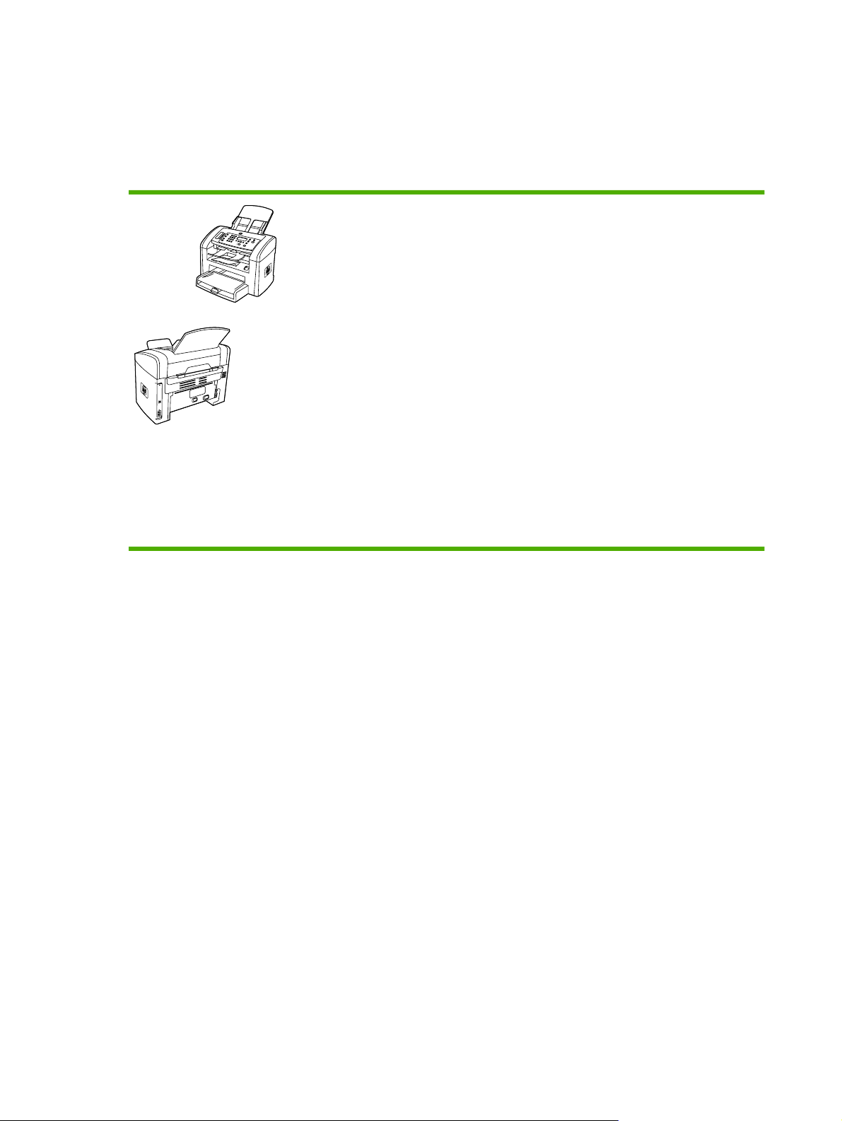
All-in-one configurations
The all-in-one is available in the following configurations.
HP LaserJet 3050 all-in-one
HP LaserJet 3050 all-in-one printer, fax, copier, scanner
Prints letter-size pages at speeds up to 19 pages per
●
minute (ppm) and A4-size pages at speeds up to 18 ppm
PCL 5e and PCL 6 printer drivers and HP postscript level
●
3 emulation.
The priority input slot holds up to 10 pages.
●
Tray 1 holds up to 250 sheets of print media or 10
●
envelopes.
Average yield for the standard black print cartridge is
●
2,000 pages in accordance with ISO/IEC 19752; actual
yield depends on specific use.
Hi-Speed universal serial bus (USB) 2.0 port
●
V.34 fax modem and 2-megabyte (MB) flash fax-storage
●
memory
64-MB random-access memory (RAM)
●
30-page automatic document feeder (ADF)
●
2 Chapter 1 Product information ENWW
Page 23
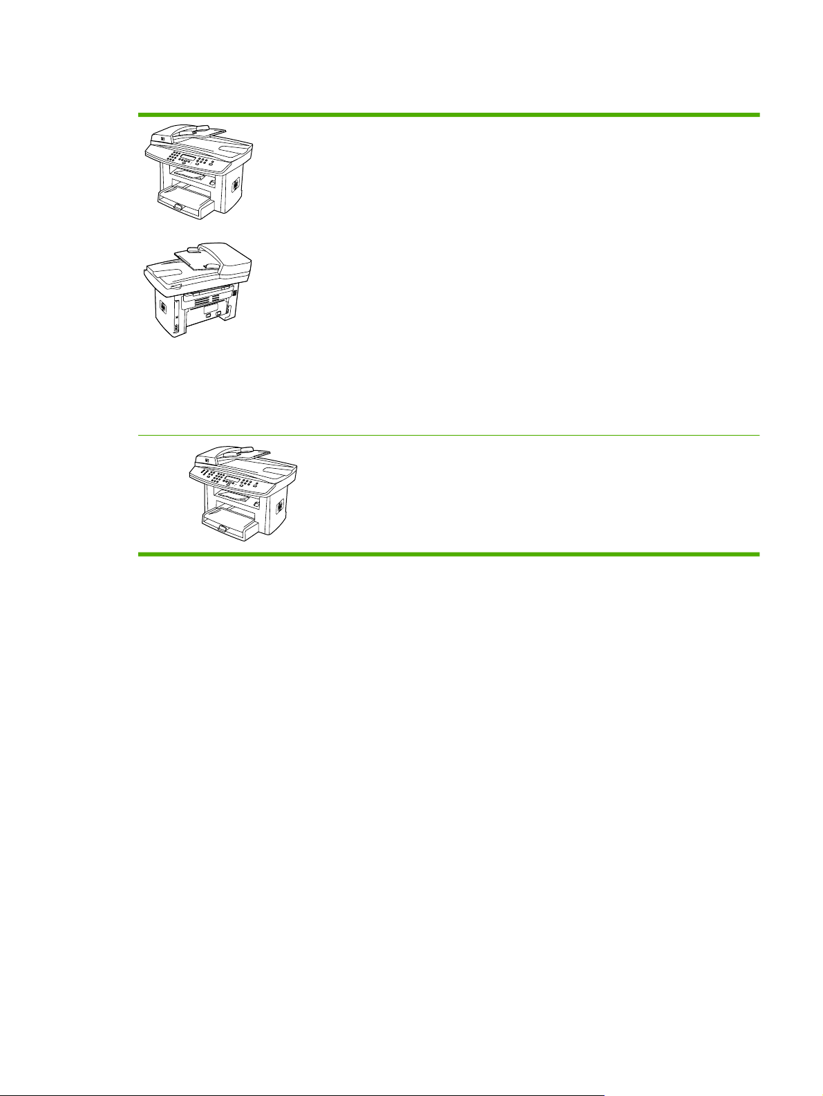
HP LaserJet 3052/3055 all-in-one
HP LaserJet 3052 all-in-one printer, scanner, copier
Prints letter-size pages at speeds up to 19 ppm and A4-
●
size pages at speeds up to 18 ppm
PCL 5e and PCL 6 printer drivers and HP postscript level
●
3 emulation
The priority input slot holds up to 10 pages.
●
Tray 1 holds up to 250 sheets of print media or 10
●
envelopes.
Average yield for the standard black print cartridge is
●
2,000 pages in accordance with ISO/IEC 19752; actual
yield depends on specific use.
Hi-Speed USB 2.0 port and port for connecting to a
●
10/100Base-T network
64-MB RAM
●
50-page automatic document feeder (ADF)
●
The HP LaserJet 3055 all-in-one printer, fax, copier,
scanner has all of the features of the HP LaserJet 3052 all-in-
one, plus:
V.34 fax modem and 2-MB flash fax-storage memory
●
ENWW All-in-one configurations 3
Page 24

All-in-one features
Excellent print quality
Fax (HP LaserJet 3050 allin-one and HP LaserJet
3055 all-in-one only)
Copy
Scan
Networking (HP LaserJet
3052/3055 all-in-one only)
1200 dots per inch (dpi) with Image REt 2400 text and graphics
●
Adjustable settings to optimize print quality
●
The HP UltraPrecise print cartridge has a finer toner formulation that provides sharper text
●
and graphics.
Full-functionality fax capabilities with a V.34 fax; includes a phone book, fax polling, and
●
delayed-fax features
For more information, see the online user guide.
Includes an ADF that accommodates faster, more efficient copy jobs with multiple-page
●
documents
For more information, see the online user guide.
The HP LaserJet 3050 all-in-one provides 600 pixels per inch (ppi), 24-bit full-color
●
scanning from the contact image sensor through the ADF.
The HP LaserJet 3052/3055 all-in-one provides 1200 ppi, 24-bit full-color scanning from
●
letter/A4-size scanner glass.
All models include an ADF that allows faster, more efficient scan jobs with multiple-page
●
documents.
For more information, see the online user guide.
TCP/IP
●
LPD
●
Printer-driver features
Automatic languageswitching
Interface connections
Environmental features
Economical printing
Supplies
Accessibility
9100
●
Fast printing performance, built-in Intellifont and TrueType scaling technologies, and
●
advanced imaging capabilities are benefits of the PCL 6 printer language.
The all-in-one automatically determines and switches to the appropriate printer language
●
(such as PS or PCL 6) for the print job.
Hi-Speed USB 2.0 port
●
10/100 ethernet (RJ45) network port (HP LaserJet 3052/3055 all-in-one only)
●
PowerSave mode (HP LaserJet 3052/3055 all-in-one only)
●
ENERGY STAR® qualified
●
N-up printing (printing more than one page on a sheet). For more information, see the
●
online user guide.
The Economode setting uses less toner.
●
No-shake cartridge design
●
The online user guide is compatible with text screen-readers.
●
Print cartridges can be installed and removed by using one hand.
●
All doors and covers can be opened by using one hand.
●
4 Chapter 1 Product information ENWW
Page 25
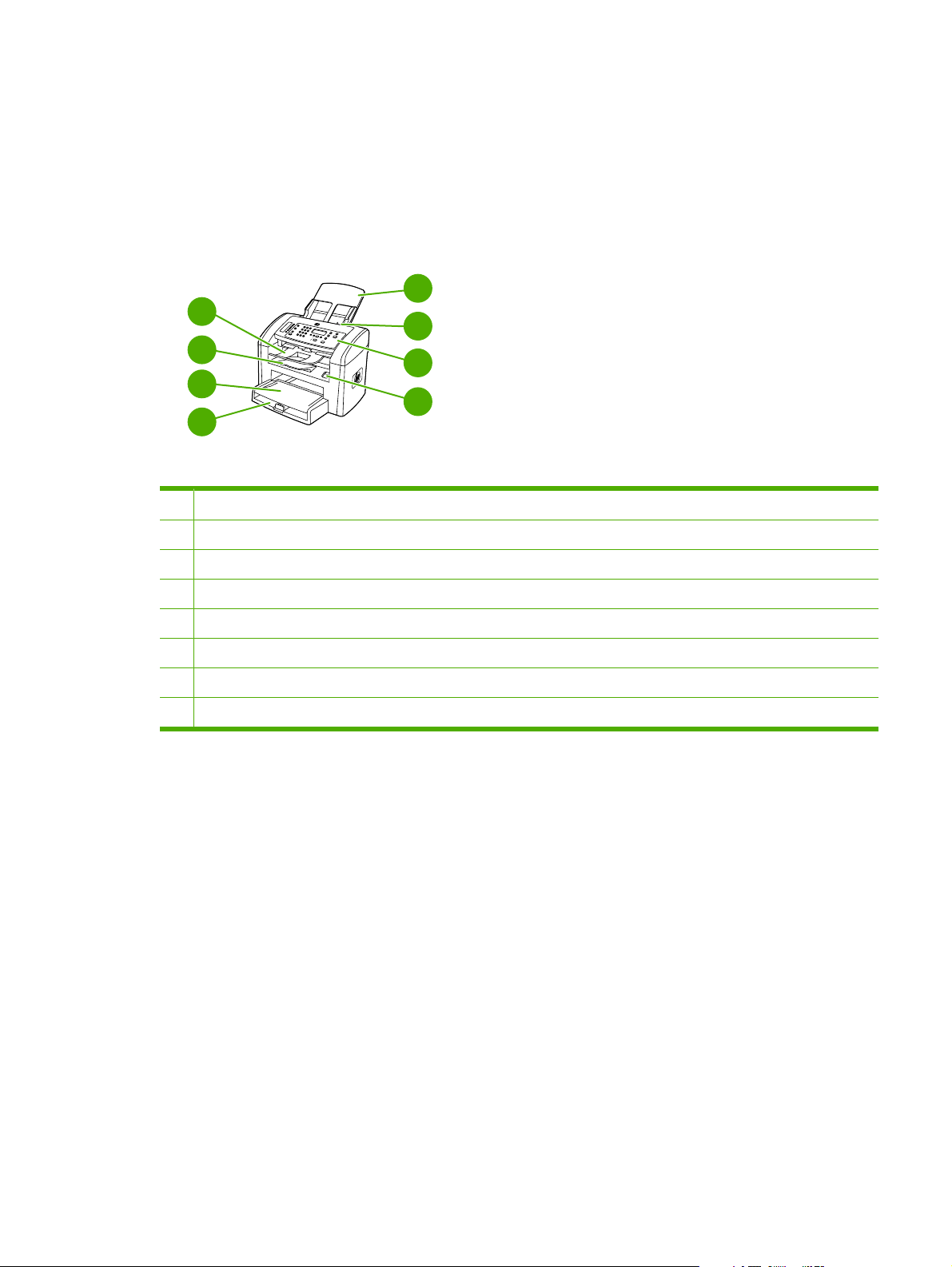
All-in-one parts
Before using the all-in-one, familiarize yourself with its parts.
HP LaserJet 3050 all-in-one parts
Front view
4
3
2
1
1 Tray 1
2 Priority input slot
3 Output bin
5
6
7
8
4 ADF output bin
5 ADF input tray
6 ADF media lever
7 Control panel
8 Cartridge-door release
ENWW All-in-one parts 5
Page 26
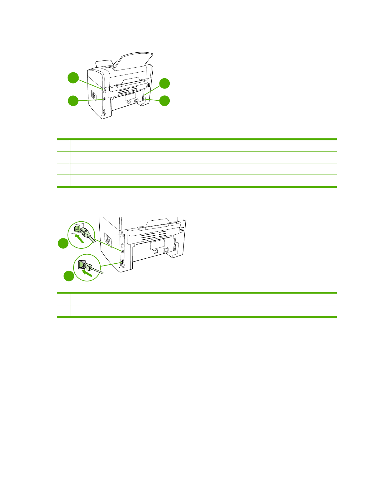
Back view
10
9
Interface ports
9
Security-lock slot
10
Power switch
11
Power receptacle
12
Interface ports
1
11
12
2
Hi-Speed USB 2.0 port
1
Fax ports
2
6 Chapter 1 Product information ENWW
Page 27

Control panel
1
1 Fax controls. Use the fax controls to change commonly used fax settings. For information about using the fax controls,
see the online user guide.
2 Alphanumeric buttons. Use the alphanumeric buttons to type data into the all-in-one control-panel display and dial
telephone numbers for faxing. For information about using alphanumeric key characters, see the online user guide.
3 Menu and cancel controls. Use these controls to select menu options, determine the all-in-one status, and cancel the
current job.
4 Copy controls. Use these controls to change commonly used default settings and to start copying. For information about
copying, see the online user guide.
5 Scan controls. Use these controls to scan to e-mail or to a folder. For information about scanning, see the online user
guide.
2 3 5
4
ENWW All-in-one parts 7
Page 28
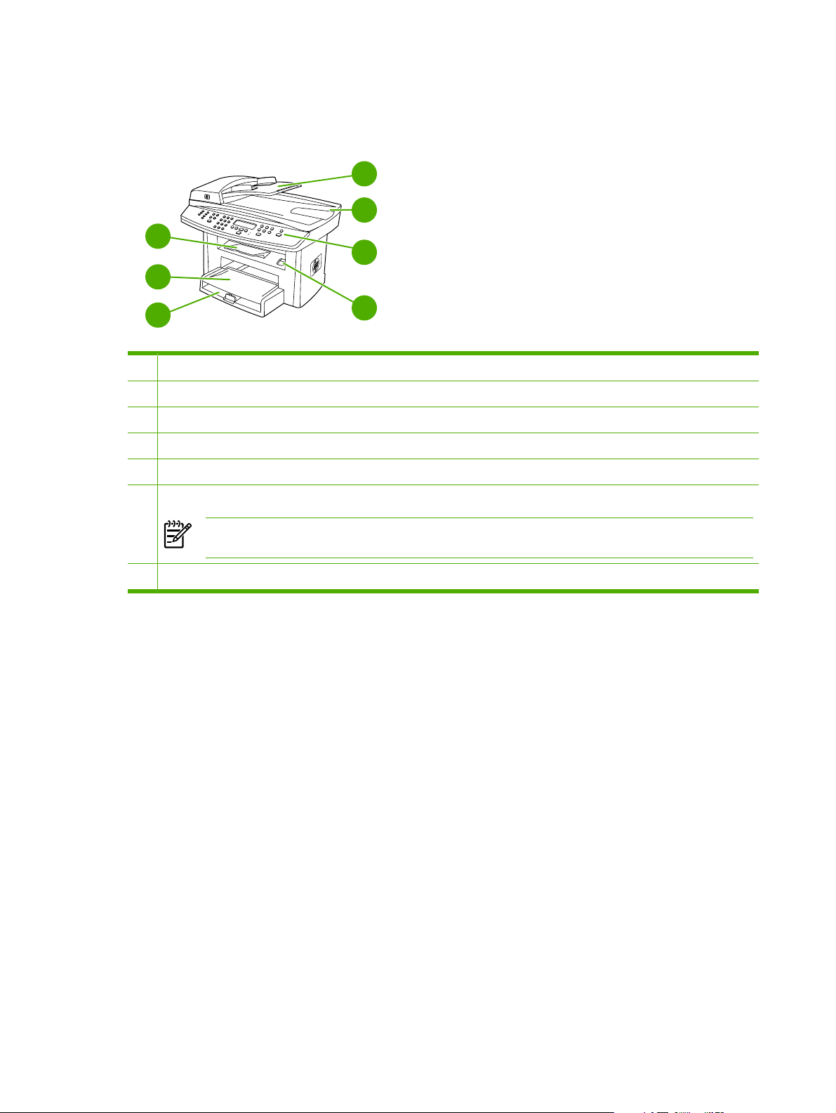
HP LaserJet 3052/3055 all-in-one parts
Front view
4
5
3
6
2
1
1 Media input tray (tray 1)
2 Priority input slot
3 Output bin
4 Automatic document feeder (ADF) input tray
5 ADF output bin
6 Control panel
NOTE The control panel for the HP LaserJet 3055 all-in-one, with fax controls, is shown. The control panel for
the HP LaserJet 3052 all-in-one does not have fax controls.
7 Cartridge-door release
7
8 Chapter 1 Product information ENWW
Page 29
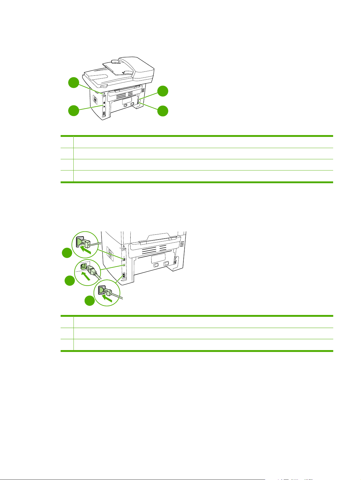
Back view
9
10
8
8 Interface ports
9 Security-lock slot
10 Power switch
11 Power receptacle
11
Interface ports
The HP LaserJet 3052/3055 all-in-one has two interface ports: a 10/100Base-T (RJ-45) network port
and a Hi-Speed USB 2.0 port. The HP LaserJet 3055 all-in-one also has fax ports.
1
2
3
1
Network port
2
Hi-Speed USB 2.0 port
3
Fax ports (HP LaserJet 3055 all-in-one only)
ENWW All-in-one parts 9
Page 30

Control panel
1
1 Fax controls (HP LaserJet 3055 all-in-one only; the HP LaserJet 3052 all-in-one does not have fax controls). Use
the fax controls to change commonly used fax settings. For information about using the fax controls, see the online user
guide.
2 Alphanumeric buttons. Use the alphanumeric buttons to type data into the all-in-one control-panel display and dial
telephone numbers for faxing. For information about using alphanumeric key characters, see the online user guide.
3 Menu and cancel controls. Use these controls to select menu options, determine the all-in-one status, and cancel the
current job.
4 Copy controls. Use these controls to change commonly used default settings and to start copying. For instructions about
copying, see the online user guide.
5 Scan controls. Use these controls to scan to e-mail or to a folder. For instructions about scanning, see the online user
guide.
2
3
4
5
10 Chapter 1 Product information ENWW
Page 31

Model and serial numbers
U
L
An identification label is located on the back of the all-in-one. This label contains the model and serial
numbers. The serial number contains information about the country/region of origin, revision level,
production code, and production number of the all-in-one. The label also contains power-rating and
regulatory information.
HEWLETT-PACKARD
11311 CHINDEN BLVD.
BOISE, IDAHO 83714
USA
Numero du produit
Product No.Q6502A
CNBR212347
CNBR212347
Numero de Serie
Serial No.
CNBR212347
CNBR212347
Product of China
Produit de Chine
é
CNMX123456
Numero reglementaire du modele
Regulatory Model Number:
BOISB-0402-03
110- 127V ~AC
50/60 Hz, 4.5A (4,5A)
Manufactured:
Fabrique le
September 23, 2005
o
N de certificacion del modem
TTDHPBO05-606
I.T.E.
53ZQ
U
CUS
L
LISTED
TestedTo Comply
With FCC Standards
FOR HOME OR OFFICE USE
US: 6DNFZ07BQ6500A
Ringer Equivalence (REN):0.7B
This product conforms with
CDRH radiation performance
standard 21 CFR chapter 1,
sub-chapter J.
NYCE
>PET<SITE:MX2
Figure 1-1 HP LaserJet 3050/3052/3055 all-in-one identification label
ENWW All-in-one parts 11
Page 32

Software installation
If the computer meets the recommended minimum requirements, you have two options when installing
the software from the CDs that came with the all-in-one.
Typical installation
The following software is included with a typical installation:
HP ToolboxFX
●
HP LaserJet Fax setup utility
●
HP LaserJet Scan program and driver
●
HP LaserJet Fax
●
Readiris OCR (not installed with other software; separate installation is required)
●
Printer drivers (PCL 6, PCL 5e, PostScript® Level 2 emulation [PS])
●
HP Director (Macintosh)
●
HP All-in-One Setup Assistant (Macintosh)
●
Minimum installation
The following software is included with a minimum installation:
PCL 6 printer driver
●
HP LaserJet Scan program and driver
●
HP LaserJet Fax setup utility
●
NOTE Minimum installation supports faxing from the control panel.
12 Chapter 1 Product information ENWW
Page 33

Printer drivers
The all-in-one comes with software that allows the computer to communicate with the all-in-one (by
using a printer language). This software is called a printer driver. Printer drivers provide access to allin-one features, such as printing on custom-sized paper, resizing documents, and inserting watermarks.
Supported printer drivers
The following printer drivers are provided for the all-in-one. If the printer driver that you want is not on
the all-in-one CD or is not available on
program that you are using, and request a driver for the all-in-one.
NOTE The most recent drivers are available at www.hp.com. Depending on the configuration
of Windows-based computers, the installation program for the all-in-one software automatically
checks the computer for Internet access in order to obtain the latest drivers.
www.hp.com, contact the manufacturer or distributor of the
Operating system
Microsoft® Windows® 98
Windows Millennium Edition (Me)
Windows 2000
Windows XP
Windows Server 2003
Mac OS X V10.3 and
Mac OS X V10.4
1
Not all all-in-one features are available from all drivers or operating systems. See the context-sensitive help in the printer driver
for available features.
2
A Macintosh printer driver and the necessary PostScript (PS) Printer Description files (PPDs) are included with the all-in-one.
1
Fax driver PCL 6 printer
X
X
X X X
driver
X
X
X
X
X
PCL 5 printer
driver
X
X
X
X
X
PS printer
driver
X
X
X
X
X
PPD2 printer
driver
Additional drivers
The following drivers are not included on the CD, but are available from the Internet.
UNIX® model scripts
●
Linux drivers
●
Windows XP 64-bit drivers
●
You can obtain Model Scripts for UNIX and Linux by downloading them from the Internet or by requesting
them from an HP-authorized service or support provider. For Linux support see
For UNIX support see
www.hp.com/go/jetdirectunix_software.
www.hp.com/go/linux.
ENWW Software installation 13
Page 34

Select the correct printer driver
Select a printer driver based on the operating system in use and the way that all-in-one is used. See
the printer-driver Help for more information.
The PCL 6 printer driver can provide the best overall performance and access to the all-in-one
●
features.
The PCL 5 printer driver is recommended for general office monochrome and color printing.
●
Use the PS driver when printing primarily from PostScript-based programs such as Adobe
●
PhotoShop
support.
NOTE The all-in-one automatically switches between PS and PCL printer languages.
®
and CorelDRAW®, for compatibility with PostScript Level 3 needs, or for PS flash font
Printer-driver Help (Windows)
The printer-driver Help is separate from program Help. The printer-driver Help provides explanations
for the buttons, check boxes, and drop-down lists that are in the printer driver. It also includes instructions
for performing common printing tasks, such as printing on both sides, printing multiple pages on one
sheet, and printing the first page or covers on different paper.
Activate the printer-driver Help screens in one of the following ways:
Click the Help button.
●
Press the F1 key on the computer keyboard.
●
Click the question-mark symbol in the upper-right corner of the printer driver.
●
Right-click on any item in the driver, and then click What's This?.
●
14 Chapter 1 Product information ENWW
Page 35

Gaining access to the printer drivers
Use one of the following methods to open the printer drivers from the computer:
Operating System To change the settings for all
print jobs until the software
program is closed
Windows 98 and
Windows Me
Windows 2000, XP,
and Server 2003
Mac OS X V10.3
and
Mac OS X V10.4
1. On the File menu in the
software program, click
Print.
2. Select the name of the all-
in-one, and then click
Properties.
The steps can vary; this
procedure is the most common.
1. On the File menu in the
software program, click
Print.
2. Select the name of the all-
in-one, and then click
Properties or
Preferences.
The steps can vary; this
procedure is the most common.
1. On the File menu, click
Print.
2. Change the settings that
you want on the various
pop-up menus.
To change the print job default
settings (for example, turn on
Print on Both Sides by default)
1. Click Start, click Settings,
and then click Printers.
2. Right-click the all-in-one
icon, and then select
Properties.
1. Click Start, click Settings,
and then click Printers or
Printers and Faxes.
2. Right-click the all-in-one
icon, and then select
Printing Preferences.
1. On the File menu, click
Print.
2. Change the settings that
you want on the various
pop-up menus.
To change the configuration
settings (for example, add a
tray or enable/disable Manual
Duplexing)
1. Click Start, click Settings,
and then click Printers.
2. Right-click the all-in-one
icon, and then select
Properties.
3. Click the Configure tab.
1. Click Start, click Settings,
and then click Printers or
Printers and Faxes.
2. Right-click the all-in-one
icon, and then select
Properties.
3. Click the Device Settings
tab.
1. Open Printer Setup Utility
by selecting the hard drive,
clicking Applications,
clicking Utilities, then
double-clicking Printer
Setup Utility.
3. On the Presets pop-up
menu, click Save as and
type a name for the preset.
These settings are saved in the
Presets menu. To use the new
settings, select the saved preset
option every time you open a
program and print.
2. Click on the print queue.
3. On the Printers menu, click
Show Info.
4. Click the Installable
Options menu.
What other software is available?
The all-in-one CDs include the HP scanning software. See the readme file on the all-in-one CD for
additional included software and for supported languages.
ENWW Software installation 15
Page 36

Software for Windows
When you install the software for Windows, you can directly connect the all-in-one to a computer by
using a USB cable, or you can connect the all-in-one to the network (HP LaserJet 3052/3055 all-in-one
only) by using the internal print server. See the getting started guide for installation instructions, and see
the readme file for the latest software information.
The following software is available to all all-in-one users, whether you connect the all-in-one directly to
a computer by using a USB cable or to the network by using a print server.
Software components for Windows
HP ToolboxFX
Perform a typical installation in order to use HP ToolboxFX.
HP ToolboxFX provides links to all-in-one status information and help information, such as this user
guide, and tools for diagnosing and solving problems. See
information.
Embedded Web server (EWS)
NOTE The EWS is not available for the HP LaserJet 3050 all-in-one.
The EWS is a Web-based interface that provides simple access to all-in-one status and configurations,
including network configurations and Smart Printing Supplies (SPS) functionality.
HP ToolboxFX on page 53 for more
Gain access to the EWS through the network connection to the all-in-one. Type the all-in-one IP address
in a Web browser to open the all-in-one EWS homepage. From the homepage, use the tabs and left
navigation menu to check the status of the all-in-one, configure the all-in-one, or check the status of the
supplies.
The following are supported browsers:
Internet Explorer 5.0 or later
●
Netscape Navigator 4.75 or later
●
Opera 6.05 or later
●
Safari 1.2 or later
●
Using Add or Remove Programs to uninstall
Use the Add or Remove Programs method in Windows to remove the all-in-one software. This method
does not require you to have the software CD.
1. Click Start, point to Settings, and click Control Panel.
-or-
In Windows XP, click Start and then click Control Panel.
2. Double-click Add or Remove Programs.
16 Chapter 1 Product information ENWW
Page 37

3. Scroll through the list of software programs and click HP LaserJet 3050/3052/3055 all-in-one.
4. Click Remove.
ENWW Software installation 17
Page 38

Software for Macintosh
For Mac OS X V10.3 and Mac OS X V10.4, use Print Center to print.
The all-in-one includes the following software for Macintosh computers.
NOTE For Macintosh computers, HP ToolboxFX is not supported.
HP Director
HP Director is a software program that is used when working with documents. When the document is
loaded into the ADF and the computer is connected directly to the all-in-one, HP Director appears on
the computer screen to initiate faxing, scanning, or changing settings on the all-in-one through Macintosh
Configure Device.
Also included is the HP all-in-one Setup Assistant, which sets up the fax and print queues.
Macintosh Configure Device (Mac OS X V10.3 and Mac OS X V10.4)
Macintosh Configure Device is a Web-based program that provides access to information about the allin-one (for example, information about supplies status and all-in-one settings). Use Macintosh Configure
Device to monitor and manage the all-in-one from the computer
NOTE Perform a complete software installation in order to use Macintosh Configure Device.
Check the all-in-one status and print information pages.
●
Check and change all-in-one system settings.
●
Check default print settings.
●
Check and change fax settings, including fax send, fax receive, fax phone book and speed-dial
●
settings, and fax reports.
Check and change network settings, including IP configuration, Advanced, mDNS, SNMP, network
●
configuration, and password.
You can view Macintosh Configure Device when the all-in-one is directly connected to the computer or
when it is connected to the network.
NOTE You do not have to have Internet access to open and use Macintosh Configure Device.
To view Macintosh Configure Device when the all-in-one is directly connected to the computer
NOTE The embedded Web server (EWS) is only available for the HP LaserJet 3052/3055 all-
in-one when using an operating system other than the Macintosh operating system. If you are
using the Macintosh operating system, the EWS is available for all of the all-in-one models.
1. Open HP Director by clicking the HP Director icon in the dock.
2. In HP Director, click Settings.
3. Select Configure device to open the Macintosh Configure Device home page in a browser.
18 Chapter 1 Product information ENWW
Page 39

To view Macintosh Configure Device when the all-in-one is connected to a network
1. Open one of the following supported Web browsers:
Safari 1.2 or later
●
Microsoft Internet Explorer 5.0 or later
●
Netscape Navigator 4.75 or later
●
Opera 6.05 or later
●
2. Type the IP address of the all-in-one into the Web browser to open the Macintosh Configure Device
home page.
PDEs (Mac OS X V10.3 and Mac OS X V10.4)
PDEs are code plug-ins that provide access to all-in-one features, such as information about the number
of copies, two-sided printing, and quality settings. An installation program for the PDEs and other
software is provided on the HP LaserJet 3050/3052/3055 all-in-one CD for Macintosh.
Installing software for Macintosh
Installing Macintosh printing system software for direct connections (USB)
This section explains how to install the printing system software for Mac OS X V10.3 and
Mac OS X V10.4.
The Apple PostScript driver must be installed in order to use the PPD files. Use the Apple PostScript
driver that came with theMacintosh computer.
To install the printing system software
1. Connect a USB cable between the USB port on the all-in-one and the USB port on the computer.
Use a standard 2-meter (6.56-foot) USB cable.
2. Insert the all-in-one CD into the CD-ROM drive and run the installer.
3. Double-click the CD icon on the desktop
4. Double-click the Installer icon.
5. Follow the instructions on the computer screen.
6. USB queues are created automatically when the all-in-one is attached to the computer. However,
the queue will use a generic PPD if the installer was not run before the USB cable was connected.
To change the queue PPD, open the Print Center or Printer Setup Utility, select the correct printer
queue, and then click Show Info to open the Printer Info dialog box. In the pop-up menu,
select Printer Model, and then, in the pop-up menu in which Generic is selected, select the correct
PPD for the all-in-one.
7. Print a test page or a page from any software program to make sure that the all-in-one software is
correctly installed.
If installation fails, reinstall the all-in-one software. If this fails, see the installation notes or latebreaking readme files on the CD or the flyer that came in the box, or go to the appropriate support
Web site for help or more information (see HP Customer Care in the user guide).
ENWW Software installation 19
Page 40

Installing Macintosh printing system software for networks
To install printer drivers for Mac OS X V10.3 and Mac OS X V10.4
1. Connect the network cable between the HP LaserJet 3052/3055 all-in-one and a network port.
2. Insert the CD into the CD-ROM drive, and then double-click the CD icon on the desktop.
3. Double-click the Installer icon in the HP LaserJet Installer folder.
4. Follow the HP all-in-one setup assistant instructions on the computer screen.
NOTE The setup assistant should prompt you to restart the computer and to provide the
IP address of the all-in-one to complete the network installation.
To remove software from Macintosh operating systems
To remove the printing software from your Macintosh computer, open the Finder, navigate to
Applications/HP LaserJet aio/HP Uninstaller, and then run the uninstaller program.
20 Chapter 1 Product information ENWW
Page 41

Choosing paper and other print media
The HP LaserJet all-in-one produces documents that have excellent print quality. You can print on a
variety of media, such as paper (including up to 100% recycled fiber content paper), envelopes, labels,
transparencies, and custom-size media.
Properties such as weight, grain, and moisture content are important factors that affect performance
and quality. To achieve the best possible print quality, only use high-quality media that is designed for
laser printers. See
specifications.
NOTE Always test a sample of the media before you purchase large quantities. Your media
supplier should understand the requirements specified in the HP LaserJet Printer Family Print
Media Guide (HP part number 5963-7863).
Supported media weights and sizes
For optimum results, use conventional 80 to 90 g/m2 (20 to 24 lb) photocopy paper. Verify that the paper
is of good quality and is free of cuts, nicks, tears, spots, loose particles, dust, wrinkles, curls, and bent
edges.
NOTE The all-in-one supports a wide range of standard and custom sizes of print media. The
capacity of trays and bins can vary depending on media weight and thickness and on
environmental conditions. Use only transparencies that are designed for use with HP LaserJet
printers. Inkjet and monochrome transparencies are not supported for the all-in-one.
Supported media weights and sizes on page 21 for detailed paper and media
Table 1-1 Priority input slot specifications, HP LaserJet 3050/3052/3055 all-in-one
Media Dimensions
Paper Minimum: 76 x 127 mm
(3 x 5 inches)
Maximum: 216 x 356 mm
(8.5 x 14 inches)
HP Cover paper
Transparencies and opaque film Thickness: 0.10 to 0.13 mm (3.9
4
Labels
Envelopes
1
The all-in-one supports a wide range of standard and custom sizes of print media. Check the printer driver for supported sizes.
2
Capacity can vary depending on media weight and thickness, and environmental conditions.
3
Hewlett-Packard does not guarantee results when printing with other types of heavy paper.
4
Smoothness: 100 to 250 (Sheffield).
3
Same as the preceding listed
minimum and maximum sizes
1
Weight Capacity
60 to 163 g/m2 (16 to 43 lb) Up to 10 sheets of 80 g/m2 or 20 lb
203 g/m2 (75 lb cover)
to 5.1 mils)
Thickness: up to 0.23 mm (up to
9 mils)
Up to 90 g/m2 (16 to 24 lb)
paper
1 sheet
1 transparency
1 sheet of labels
Up to 10
2
ENWW Choosing paper and other print media 21
Page 42

Table 1-2 Media input tray (tray 1) specifications, HP LaserJet 3050/3052/3055 all-in-one
Media Dimensions
Minimum size 76 x 127 mm (3.0 x 5.0 inches)
1
Weight Capacity
60 to 163 g/m2 (16 to 43 lb) 250 sheets of 80 g/m2 or
Maximum size 216 x 356 mm (8.5 x 14 inches)
Letter 216 x 279 mm (8.5 x 11 inches)
A4 210 x 297 mm (8.3 x 11.7 inches)
Legal 216 x 356 mm (8.5 x 14 inches)
16K (195 x 270 mm) 195 x 270 mm (7.7 x 10.6 inches)
16K (7.75 x 10.75 inch) 197 x 273 mm (7.8 x 10.7 inches)
16K (184 x 260 mm) 184 x 260 mm (7.2 x 10.2 inches)
A5 148 x 210 mm (5.8 x 8.3 inches)
B5 (ISO) 176 x 250 mm (6.9 x 9.9 inches)
B5 (JIS) 182 x 257 mm (7.2 x 10 inches)
Double postcard (JIS) 148 x 200 mm (5.83 x 7.87 inches)
Executive 191 x 267 mm (7.3 x 10.5 inches)
8.5 x 13 inches 216 x 330 mm (8.5 x 13 inches)
Envelope, monarch 98 x 191 mm (3.875 x 7.7 inches)
2
20 lb paper
Envelope, DL 110 x 220 mm (4.33 x 8.66 inches)
Envelope, C5 162 x 229 mm (6.38 x 9.01 inches)
Envelope, B5 176 x 250 mm (6.93 x 9.84 inches)
Envelope, # 10 104.9 x 241.3 mm (4.125 x 9.5 inches)
1
The all-in-one supports a wide range of standard and custom sizes of print media. Check the printer driver for supported sizes.
2
Capacity can vary depending on the media weight and thickness, and environmental conditions.
Table 1-3 ADF specifications, HP LaserJet 3050 all-in-one
Media Dimensions Weight or thickness Capacity
Minimum size 148 x 105 mm (5.83 x 4.13 inches)
Maximum size 216 x 381 mm (8.5 x 15 inches)
1
For legal-sized (216 x 356 mm; 8.5 x 14 inches) and larger media, feed one sheet at a time through the ADF.
60 to 105 g/m2 (16 to 28 lb) 30 sheets of 80 g/m2 or 20 lb bond
1
Table 1-4 ADF specifications, HP LaserJet 3052/3055 all-in-one
Media Dimensions Weight or thickness Capacity
Minimum-size 127 x 127 mm (5 x 5 inches)
60 to 90 g/m2 (16 to 24 lb bond) 50 sheets of 80 g/m2 or 20 lb bond
Maximum-size 216 x 381 mm (8.5 x 15 inches)
22 Chapter 1 Product information ENWW
Page 43

NOTE When faxing, copying, or scanning using the HP LaserJet 3052/3055 all-in-one, use the
flatbed scanner if the original is fragile, thin, thick, too small for the ADF, or a photograph. Also
use the flatbed scanner for the fit-to-page copying feature. The flatbed scanner provides the best
fax, copy, and scan resolution.
Media to avoid
The all-in-one can handle many types of media. Using media that is outside the specifications degrades
print quality and increases the chance of jams occurring.
Do not use media that is too rough.
●
Do not use media that contains cutouts or perforations other than standard 3-hole punched paper.
●
Do not use multipart forms.
●
Do not use paper that contains a watermark if you are printing solid patterns.
●
Media that can damage the all-in-one
In rare circumstances media can damage the all-in-one. Avoid the following types of media to prevent
possible damage:
Do not use media with staples attached.
●
Do not use transparencies that are designed for inkjet printers or other low-temperature printers.
●
Use only transparencies that are specified for use with HP LaserJet printers.
Do not use photo paper intended for inkjet printers.
●
Do not use paper that is embossed or coated and is not designed for the temperature of the image-
●
fuser. Select media that can tolerate temperatures of 200°C (392°F) for 0.1 second.
HP manufactures a media that is designed for the all-in-one.
Do not use letterhead paper that was produced with low-temperature dyes or thermography.
●
Preprinted forms or letterhead must use inks that can tolerate temperatures of 200°C (392°F) for
0.1 second.
Do not use any media that produces emissions, or that melts, offsets, or discolors when exposed
●
to 200°C (392°F) for 0.1 second.
To order HP LaserJet printing supplies, go to
ghp/buyonline.html/ worldwide.
www.hp.com/go/ljsupplies in the U.S. or to www.hp.com/
ENWW Choosing paper and other print media 23
Page 44

24 Chapter 1 Product information ENWW
Page 45

2 Operation
Site preparation
●
Unpacking
●
Installing input devices
●
Installing the print cartridge
●
Loading media into the input trays
●
ENWW 25
Page 46

Site preparation
Prepare the location
Place the all-in-one on a sturdy, level surface in a well-ventilated area. Make sure that the air vents are
not blocked and all doors can open freely.
Operating environment
Place the product on a sturdy, level surface in a well-ventilated area that meets the following
environmental requirements:
Temperature (operating): 15° to 32.5°C (59° to 90.5°F)
●
Temperature (storage): -20° to 40°C (-4° to 104°F)
Humidity (operating): 10% to 80% relative humidity (no condensation)
●
Humidity (storage): less than 95% relative humidity (no condensation)
Away from direct sunlight, open flames, and ammonia fumes
●
Sufficient space around the product to allow for access and ventilation
●
460 mm (18.1 inches)
430 mm (16.9 inches)
443 mm
(17.4 inches)
Figure 2-1 HP LaserJet 3050 all-in-one dimensions
(15.5 inches)
393 mm
497 mm
(19.6 inches)
406 mm
(15.98 inches)
Figure 2-2 HP LaserJet 3052/3055 all-in-one dimensions
26 Chapter 2 Operation ENWW
Page 47

Minimum system requirements
Windows® 2000
●
Windows XP
●
Windows Millennium Edition (Me)
●
Windows Server 2000
●
Windows 98
●
Mac OS X V10.3 and later
●
128 MB RAM for Windows operating systems
●
32 MB RAM for Macintosh operating systems
●
250 MB hard-disk space (full installation)
●
CD-ROM drive
●
USB port
●
ENWW Site preparation 27
Page 48

Unpacking
Contents of the HP LaserJet 3050 all-in-one box
A new HP LaserJet 3050 all-in-one printer, fax, copier, scanner should contain all of the items shown
Figure 2-3 HP LaserJet 3050 all-in-one box contents on page 28.
in
7
8
9
Figure 2-3 HP LaserJet 3050 all-in-one box contents
1
2
3
4
5
6
7
8
9
10
11
Print cartridge
Power cord
Fax cord
Media input tray (tray 1)
Software and the online user guide on CD
Start guide and support flyer
ADF input tray
Output bin support
ADF output support
HP LaserJet 3050 all-in-one printer, fax, copier, scanner
Control-panel overlay (if not already installed)
NOTE The USB cable is not included.
11
10
28 Chapter 2 Operation ENWW
Page 49

Contents of the HP LaserJet 3052/3055 all-in-one box
A new HP LaserJet 3052 all-in-one printer, scanner, copier or HP LaserJet 3055 all-in-one printer, fax,
copier, scanner should contain all of the items shown in
box contents on page 29.
Figure 2-4 HP LaserJet 3052/3055 all-in-one
2
6
1
5
3
10
4
Figure 2-4 HP LaserJet 3052/3055 all-in-one box contents
1
2
3
4
5
6
7
ADF input tray
HP LaserJet 3052 all-in-one printer, scanner, copier or HP LaserJet 3055 all-in-one printer, fax, copier, scanner
Power cord
Fax cord (HP LaserJet 3055 all-in-one only)
Print cartridge
Start guide and support flyer
Software and online user guide on CD
7
8
9
8
9
10
Media input tray (tray 1)
Output bin support
Control-panel faceplate (if not already installed)
NOTE The USB and network cables are not included.
ENWW Unpacking 29
Page 50

Installing input devices
To install the media input tray
1. Remove any shipping tape from the inside and outside of the tray.
2. Slide the tray in until it fits securely.
To install the output bin support
1. Insert the pin on one side of the support into the hole in the all-in-one.
2. Flex the pin on the other side inward, and insert it into the hole.
1
2
To install the ADF output support (HP LaserJet 3050 all-in-one only)
1. Insert the pin on one side of the support into the hole in the all-in-one.
30 Chapter 2 Operation ENWW
Page 51

2. Flex the pin on the other side inward, and insert it into the hole.
To install the automatic document feeder (ADF) input tray
1. Align the two tabs on the input tray with the two grooves in the ADF lid.
2. Slide the tray into the grooves until the tray snaps into place.
HP LaserJet 3050 HP LaserJet 3052/3055
ENWW Installing input devices 31
Page 52

Installing the print cartridge
To install the print cartridge
1. Press the cartridge-door release to open the print-cartridge door.
HP LaserJet 3050 HP LaserJet 3052/3055
2. Remove the print cartridge from its packaging, and then rock the cartridge gently five or six times.
3. Bend the plastic tab at the end of the cartridge.
4. Pull the tab until all of the sealing tape is removed from the cartridge.
32 Chapter 2 Operation ENWW
Page 53

5. Hold the print cartridge by the handle and insert it into the all-in-one and then close the print-
cartridge door.
CAUTION If toner gets on your clothing, wipe the toner off with a clean cloth, and then wash
the items in cold water and air dry them. Hot water or heat from a dryer sets the toner in the fabric.
NOTE Hewlett-Packard Company cannot recommend using non-HP print cartridges, whether
they are new, refilled, or remanufactured. Because they are not HP products, HP cannot influence
their design or control their quality.
ENWW Installing the print cartridge 33
Page 54

Loading media into the input trays
The following sections describe how to load media into the different input trays.
CAUTION Printing on wrinkled, folded, or damaged media can cause jams. See Media to avoid
on page 23 for more information.
Loading documents to fax, copy, or scan
Use these instructions to load originals into the all-in-one for scanning. For the best quality scans, use
the flatbed scanner.
To load originals onto the flatbed scanner (HP LaserJet 3052/3055 all-in-one only)
1. Make sure that the ADF contains no media.
2. Lift the flatbed scanner cover.
3. Place the original document face-down on the flatbed scanner with the upper-left corner of the
document at the lower-right corner of the glass.
4. Gently close the lid.
The document is ready to be faxed/copied/scanned.
To load originals into the automatic document feeder (ADF)
NOTE The ADF capacity for the HP LaserJet 3050 all-in-one is up to 30 sheets of 80 g/m
20 lb media. The ADF capacity for the HP LaserJet 3052/3055 all-in-one is up to 50 sheets of 80
2
g/m
or 20 lb media.
2
or
34 Chapter 2 Operation ENWW
Page 55

CAUTION To prevent damage to the all-in-one, do not use an original that contains correction
tape, correction fluid, paper clips, or staples. Also, do not load photographs, small originals, or
fragile originals into the ADF.
1. For the HP LaserJet 3050 all-in-one, insert the top-end of the stack of originals into the ADF input
tray, with the media stack face-down and the first page to be copied at the bottom of the stack.
If you are using heavy media (for example, cardstock) make sure that the ADF media lever is
positioned in the single-page setting (only load one page of heavy media). For all other media
types, make sure that the ADF media lever is positioned in the multiple-page setting (no matter
how many pages will be loaded).
-or-
For the HP LaserJet 3052/3055 all-in-one, insert the top-end of the stack of originals into the ADF
input tray, with the media stack face-up and the first page to be copied on top of the stack.
2. Slide the stack into the ADF until it does not move any farther.
HP LaserJet 3050
Document Loaded appears on the control-panel display.
3. Adjust the media guides until they are snug against the media.
HP LaserJet 3050
4. The document is now ready to be faxed/copied/scanned.
HP LaserJet 3052/3055
HP LaserJet 3052/3055
ENWW Loading media into the input trays 35
Page 56

Loading input trays
Priority input slot
The priority input slot holds up to 10 sheets of media up to 163 g/m2 (43 lb) in weight or 1 envelope,
transparency, or card. Load media with the top forward and the side to be printed facing up. To prevent
jams and skewing, always adjust the side media guides before feeding the media.
250-sheet input tray (tray 1)
The input tray holds up to 250 pages of 80 g/m2 or 20 lb paper, or fewer pages of heavier media (25 mm
[0.9 inch] or shorter stack height). Load media with the top forward and the side to be printed facing
down. To prevent jams and skewing, always adjust the side and rear media guides.
NOTE When you add new media, make sure that you remove all of the media from the input
tray and straighten the stack of new media. This helps to prevent multiple sheets of media from
feeding into the all-in-one, which can cause jams.
36 Chapter 2 Operation ENWW
Page 57

3 Maintenance
Managing supplies
●
Cleaning the all-in-one
●
Calibrating the scanner
●
Managing and maintaining the all-in-one
●
ENWW 37
Page 58

Managing supplies
Life expectancies of print cartridges and parts that wear
Inspect any parts that wear when servicing the product. Replace them as needed, based on failure or
wear rather than on usage.
The following table lists approximate schedules for replacing consumables.
Table 3-1 Life expectancies
Product name Description Part number
HP LaserJet 3050/3052/3055 all-in-one 10,000 pages-per-month
50,000 pages lifetime
Black print cartridge
Separation pad and pickup rollers Replace when the all-in-one is picking up multiple sheets or no
1
The estimated print-cartridge life is based on using letter- or A4-sized paper with an average of 5% toner coverage and a
medium density-setting. Print-cartridge life can be extended by using draft-mode settings to conserve toner.
1
Average yield for the standard print cartridge is approximately
2,000 pages. Actual yield depends on use.
sheets and trying different media did not resolve the problem.
NA
Q2612A
See Parts and
diagrams
on page 281 for
ordering
information.
Ordering supplies
HP direct ordering for accessories or supplies
United States:
●
Canada:
●
Europe:
●
Asia-Pacific:
●
www.hp.com/sbso/product/supplies
www.hp.ca/catalog/supplies
www.hp.com/supplies
www.hp.com/paper/
To order genuine HP parts or accessories, go to the HP Parts Store at
www.hp.com/buy/parts (U.S. and
Canada only), or call 1-800-538-8787 (U.S.) or 1-800-387-3154 (Canada).
Storing print cartridges
Follow these guidelines for storing print cartridges:
Do not remove the print cartridge from its package until you are ready to use it.
●
CAUTION To prevent damage, do not expose the print cartridge to light for more than a
few minutes.
See
●
●
●
38 Chapter 3 Maintenance ENWW
Environmental specifications on page 349 for operating and storage temperature ranges.
Store the supply in a horizontal position.
Store the supply in a dark, dry location away from heat and magnetic sources.
Page 59

Replacing and recycling supplies
Changing the print cartridge
For information about how to install a new print cartridge, see To install the print cartridge on page 32.
CAUTION If toner gets on your clothing, wipe it off with a dry cloth and wash the clothing in cold
water. Hot water sets toner into the fabric.
NOTE To recycle supplies, place the used supply in the box in which the new supply arrived.
Use the enclosed return label to send the used supply to HP for recycling. For complete
information, see the recycling guide that is included with each new HP supply item. See
HP LaserJet printing supplies on page 358 for more information about HP's recycling program.
Changing the ADF pickup roller and load-arm assembly (HP LaserJet 3052/3055 all-in-one)
For information about how to install pickup roller and load-arm assembly, see ADF pickup roller and
load-arm assembly (HP LaserJet 3052/3055 all-in-one) on page 143.
HP policy on non-HP supplies
Hewlett-Packard Company cannot recommend the use of non-HP supplies, either new or
remanufactured. Because they are not HP products, HP cannot influence their design or control their
quality. Service or repairs required as a result of using a non-HP supply will not be covered under the
warranty.
When you insert a supply into the all-in-one, the all-in-one will generate a message if the supply is not
a genuine HP supply. If you insert a used, genuine HP supply that is nearing the end of its useful life,
then the all-in-one identifies the supply as non-HP. Simply return the supply to the original device to
reactivate the HP features and functionality.
HP fraud hotline
Call the HP fraud hotline if the all-in-one or HP ToolboxFX indicates that the print cartridge is not an
HP print cartridge and you think that it is genuine. HP will help determine if the product is genuine and
take steps to resolve the problem.
The print cartridge might not be a genuine HP one if you notice the following issues:
A large number of problems occur with the print cartridge.
●
The print cartridge does not look like it usually does (for example, the pull tab or the box is different).
●
In the United States, call toll-free: 1-877-219-3183.
Outside the United States, you can call collect. Dial the operator and ask to place a collect call to this
telephone number: 1-770-263-4745. If you do not speak English, a representative at the HP fraud hotline
who speaks your language will assist you. Or, if someone who speaks your language is not available,
a language-line interpreter will connect approximately 1 minute after the beginning of the call. The
language line interpreter is a service that will translate between you and the representative for the HP
fraud hotline.
ENWW Managing supplies 39
Page 60

Cleaning the all-in-one
To clean the exterior
Use a soft, damp, lint-free cloth to wipe dust, smudges, and stains off of the exterior of the all-in-one.
To clean the ADF scanner glass and white platen (HP LaserJet 3050 all-in-one)
Over time, specks of debris might collect on the ADF scanner glass and white platen, which can affect
performance. Use the following procedure to clean the ADF scanner glass and white platen.
NOTE When vertically-aligned black streaks or smears appear on successive copies produced
by using the ADF, the ADF scanner glass or white platen needs to be cleaned.
1. Use the power switch to turn off the all-in-one, and then unplug the power cord.
2. Tilt the control panel forward.
40 Chapter 3 Maintenance ENWW
Page 61

3. Clean the ADF scanner glass and the white platen with a soft cloth or sponge that has been
moistened with nonabrasive glass cleaner.
CAUTION Do not use abrasives, acetone, benzene, ammonia, ethyl alcohol, or carbon
tetrachloride on any part of the all-in-one; these can damage the all-in-one. Do not place
liquids directly on the glass or platen. They might seep and damage the all-in-one.
4. Dry the glass and platen with a chamois or a cellulose sponge to prevent spotting.
5. Plug in the all-in-one and then turn it on.
ENWW Cleaning the all-in-one 41
Page 62

To clean the flatbed glass and the ADF scanner glass (HP LaserJet 3052/3055 all-in-one)
Dirty glass, from fingerprints, smudges, hair, and other causes, slows down performance and affects
the accuracy of special features such as fit-to-page and copy.
NOTE If streaks or other defects appear only on copies produced by using the ADF, clean the
ADF scanner glass (step 3). It is not necessary to clean the flatbed glass.
1. Turn off the all-in-one, unplug the power cord, and then raise the lid.
2. Clean the flatbed glass by using a soft cloth or sponge that has been moistened with nonabrasive
glass cleaner.
CAUTION Do not use abrasives, acetone, benzene, ammonia, ethyl alcohol, or carbon
tetrachloride on any part of the all-in-one; these can damage the all-in-one. Do not place
liquids directly on the glass. They might seep under it and damage the all-in-one.
3. Clean the ADF scanner glass by using a soft cloth or sponge that has been moistened with
nonabrasive glass cleaner.
4. To prevent spotting, dry the glass by using a chamois or cellulose sponge.
42 Chapter 3 Maintenance ENWW
Page 63

To clean the lid backing (HP LaserJet 3052/3055 all-in-one)
Minor debris can accumulate on the white document lid backing that is located underneath the all-inone lid.
1. Turn off the all-in-one, unplug the power cord, and then raise the lid.
2. Clean the white document lid backing by using a soft cloth or sponge that has been moistened with
a mild soap and warm water. Also clean the white strip next to the lid backing.
3. Wash the backing gently to loosen debris; do not scrub the backing.
4. Dry the backing by using a chamois or soft cloth.
CAUTION Do not use paper-based wipes, because they might scratch the backing.
5. If this does not clean the backing well enough, repeat the previous steps and use isopropyl alcohol
to dampen the cloth or sponge, and then wipe the backing thoroughly with a damp cloth to remove
any residual alcohol.
ENWW Cleaning the all-in-one 43
Page 64

To clean the ADF pickup-roller assembly (HP LaserJet 3052/3055 allin-one)
If the ADF has trouble feeding documents, you can clean the ADF pickup-roller assembly.
1. Turn off the all-in-one and unplug the power cord.
2. Open the ADF cover.
3. Press the round green button while lifting the green lever. Rotate the green lever until it stops in
the open position. The pickup-roller assembly should remain on the surface.
4. Remove the assembly, and then wipe it with a soft, dry cloth.
44 Chapter 3 Maintenance ENWW
Page 65

5. Return the assembly to the same place in the ADF. The largest roller goes in back, and the gear
side is away from you.
6. Lower the green lever until the flat green part fits in between the rollers. Press down on the green
lever until you hear a snap.
7. To check for correct installation, lift the green lever until it remains open. The pickup-roller assembly
should be secured to the lever assembly and should not fall out.
8. Make sure that the green hooks secure both sides of the assembly.
ENWW Cleaning the all-in-one 45
Page 66

9. Lower the green lever assembly and close the ADF cover.
10. Plug in the all-in-one, and then turn it on.
46 Chapter 3 Maintenance ENWW
Page 67

Cleaning the paper path
During the printing process, paper, toner, and dust particles can accumulate inside the all-in-one. Over
time, this buildup can cause print-quality problems such as toner specks or smearing. This all-in-one
has a cleaning mode that can correct and prevent these types of problems.
To clean the paper path from HP ToolboxFX
Use HP ToolboxFX to clean the paper path. This is the recommended cleaning method. If you do not
have access to HP ToolboxFX, use the method in
panel on page 48.
1. Make sure that the all-in-one is turned on and in the Ready state.
2. Open HP ToolboxFX.
3. On the System Settings tab, click Service, click Begin cleaning mode, and then click Start. A
page with a pattern prints from the all-in-one.
4. At the all-in-one, remove any print media that might be in tray 1. Load the page that printed face-
down into tray 1.
5. Press
to begin the cleaning process.
To clean the paper path from the all-in-one control
ENWW Cleaning the all-in-one 47
Page 68

To clean the paper path from the all-in-one control panel
If you do not have access to HP ToolboxFX, you can print and use a cleaning page from the all-in-one
control panel.
1. Press Menu.
2. Use the < or the > button to find the Service menu, and then press
3. Use the < or the > button to find Cleaning Mode, and then press
4. Load plain letter or A4 paper when you are prompted.
5. Press
A page feeds slowly through the all-in-one. Discard the page when the process is completed.
again to begin the cleaning process.
.
.
48 Chapter 3 Maintenance ENWW
Page 69

Calibrating the scanner
The scanner calibrates itself automatically at the start of scan of copy jobs. Normally, you do not need
to initiate the calibration, but you can initiate the calibration through the secondary service menu and
produce a report that shows the calibration results. See
Secondary service menu on page 251.
ENWW Calibrating the scanner 49
Page 70

Managing and maintaining the all-in-one
Information pages
Information pages reside within the all-in-one memory. These pages help you to diagnose and solve
problems with the all-in-one.
NOTE If the all-in-one language was not correctly set during installation, you can set the
language manually so that the information pages print in one of the supported languages. Change
the language by using HP ToolboxFX. See
Demo page
1. On the all-in-one control panel, press Menu.
HP ToolboxFX on page 53.
2. Use the < or > button to select Reports, and then press
3. Use the < or > button to select Demo page, and then press
You can also view this page from HP ToolboxFX.
.
Usage page
1. On the all-in-one control panel, press Menu.
2. Use the < or > button to select Reports, and then press
3. Use the < or > button to select Usage page, and then press
.
.
.
50 Chapter 3 Maintenance ENWW
Page 71

Configuration page
The configuration page lists the current settings and properties of the all-in-one. To print the configuration
page from the all-in-one, complete the following steps.
Figure 3-1 Sample configuration page on page 51 shows a sample configuration page. Descriptions
of the sections on a configuration page appear below the figure.
1. On the all-in-one control panel, press Menu.
2. Use the < or > button to select Reports, and then press
3. Use the < or > button to select Config report, and then press
.
hp LaserJet 3055
Self Test / Configuration
1
2
3
5
6
7
4
8
.
Figure 3-1 Sample configuration page
1. Product Information. This section contains basic information about the all-in-one, such as the
product name and the serial number.
2. Memory. This section lists memory-related information, such as the total memory that is installed.
3. Paper Settings. This section lists information about the media type for each tray and about the
type settings for all the media that the all-in-one supports.
4. Copy Settings. This section lists the all-in-one default copy settings.
5. Product Settings. This section lists information that is gathered during software installation,
including the language and the company name.
6. Installed Personalities and Options. This section contains information about installed print
drivers.
ENWW Managing and maintaining the all-in-one 51
Page 72

7. Print Settings. This section contains information about all-in-one settings that are configured in
the printer driver or in HP ToolboxFX.
8. Status Log. This section contains information about all-in-one errors.
A second page also prints. On that page, the Fax Settings section provides details about the all-in-one
fax settings.
Network configuration page
The network configuration page lists the all-in-one network settings. To print from the all-in-one,
complete the following steps:
1. On the all-in-one control panel, press
2. Use the < or > button to select Reports, and then press
3. Use the < or > button to select Network config., and then press
.
.
Fax logs and reports
For information about fax logs and reports, see the online user guide.
.
52 Chapter 3 Maintenance ENWW
Page 73

HP ToolboxFX
HP ToolboxFX is a Web-based program that you can use to complete the following tasks:
Check the all-in-one status.
●
Configure the all-in-one settings.
●
View troubleshooting information.
●
View online documentation.
●
You can view HP ToolboxFX when the all-in-one is directly connected to a computer or when it is
connected to a network. You must perform a typical software installation in order to use HP ToolboxFX.
NOTE HP ToolboxFX is not supported for Windows 98 SE or Macintosh operating systems. To
use HP ToolboxFX, the TCP/IP protocol must be installed on the computer.
NOTE You do not have to have Internet access to open and use HP ToolboxFX.
To view HP ToolboxFX
Open HP ToolboxFX in one of these ways:
In the Windows system tray or on your desktop, double-click the HP ToolboxFX icon.
●
On the Windows Start menu, click Programs (or All Programs in Windows XP), click HP, click
●
HP LaserJet 3050/3052/3055 all-in-one, and then click HP ToolboxFX.
The HP ToolboxFX software contains the following sections, which are described in this document:
Status on page 54
●
Fax on page 55
●
Help on page 57
●
System settings on page 58
●
Print settings on page 60
●
Network settings on page 60
●
ENWW Managing and maintaining the all-in-one 53
Page 74

Status
The HP ToolboxFX Status tab contains links to the following main pages:
Device Status. View all-in-one status information. This page indicates all-in-one conditions such
●
as a jam or an empty tray. After you correct a problem with the all-in-one, click Refresh Status to
update the all-in-one status.
Supplies status. View all-in-one supplies status information.
●
Device Configuration. View a detailed description of the current all-in-one configuration, including
●
the amount of memory installed and whether optional trays are installed.
Network Configuration. View a detailed description of the current network configuration, including
●
the IP address and network status.
Print Info Pages. Print the configuration page and various other information pages that are
●
available for the all-in-one, such as the demo page.
Event Log. View a history of all-in-one errors. The most recent error is at the top of the list.
●
Event log
The Event log is a four-column table where the all-in-one events are logged for your reference. The log
contains codes that correspond to the error messages that appears on the all-in-one control-panel
display. The number in the Page Count column specifies the total number of pages that the all-in-one
had printed when the error occurred. The Event log also contains a brief description of the error. For
more information about error messages, see
Control-panel messages on page 199.
54 Chapter 3 Maintenance ENWW
Page 75

Fax
Use the HP ToolboxFX Fax tab to perform fax tasks from the computer. The Fax tab contains links to
the following main pages:
Fax Tasks. Perform such tasks as sending a fax or clearing the fax memory, or set the fax-receive
●
mode.
Fax Phone Book. Add, edit, or delete entries in the all-in-one phone book.
●
Fax Send Log. View all of the recent faxes that have been sent from the all-in-one.
●
Fax Receive Log. View all of the recent faxes that have been received by the all-in-one.
●
Fax Data Properties. Manage the space used to store faxes on a computer. These settings apply
●
only if you have chosen to send or receive faxes remotely from the computer.
Fax tasks
The following three options are available when receiving a fax:
Print the fax. An option is available to have a message appear on the computer to notify when the
●
fax was printed.
Receive the fax on the computer. An option is available to have a message appear on the computer
●
to notify when the fax arrives. If the fax machine is connected to multiple computers, only one
computer can be designated to receive faxes.
Forward the fax to another fax machine.
●
For more information about fax tasks, see the online user guide.
NOTE You must click Apply before the changes take effect.
Fax phone book
Use the HP ToolboxFX Fax phone book to add and remove individuals or groups on a speed-dial list,
import phone books from a variety of sources, and update and maintain a contact list.
To add an individual contact to a speed-dial list, select the check box next to the speed dial number
●
that you want to specify. Type the contact name in the Contact name window. Type the fax number
in the Fax number window. Click Add/Edit.
To add a group of contacts to a speed-dial list, select the check box next to the speed-dial number
●
that you want to specify. Click New/Edit Group. Double-click a contact name from the list on the
left to move it to the group list on the right, or select a name on the left and then click the appropriate
arrow to move it to the group list on the right. You can also use those two methods to move names
from right to left. When you have created a group, type a name in the Group name window, and
then click OK.
To edit an existing individual speed-dial entry, click anywhere on the row containing the contact
●
name to select it, type changes in the appropriate windows, and then click Add/Edit. You can also
make changes directly in the phone book directory list by clicking the entry and typing the changes.
Make sure that you do not have a check mark in the Select column.
To edit an existing group-speed-dial entry, click anywhere on the row containing the group name
●
to select it, and then click New/Edit Group. Make any required changes, and then click OK. You
ENWW Managing and maintaining the all-in-one 55
Page 76

can make changes to the name of the group directly in the phone book directory list by clicking the
entry and typing the changes. Make sure that you do not have a check mark in the Select column.
To delete an entry from the speed-dial list, select the item and then click Delete.
●
To move speed dial entries, select the entry and then click Move, or select Move and then specify
●
the entry in the dialog box. Either select Next empty row or specify the number of the row where
you want to move the entry.
NOTE If you specify a row that is occupied, the new entry will overwrite the existing entry.
To import contacts from a phone book that exists in Lotus Notes, Outlook, or Outlook Express, click
●
Import Phone Book. Select the appropriate software program, navigate to the appropriate file,
and then click OK. You can also select individual entries from the phone book instead of importing
the entire phone book.
To select all of the entries in a speed-dial list, click the Select column heading.
●
In addition to numerical digits, the following are valid characters for fax numbers:
(
●
)
●
+
●
-
●
*
●
#
●
R
●
W
●
.
●
,
●
<space>
●
NOTE You must click Apply before your changes take effect.
For more information about faxes, see the online user guide.
56 Chapter 3 Maintenance ENWW
Page 77

Fax Send Log
The HP ToolboxFX Fax send log lists all recently sent faxes and information about them, including the
date and time sent, job number, fax number, page count, and the results.
When you send a fax from a computer that is connected to the all-in-one, the fax contains a View link.
Clicking this link opens a new page that provides information about the fax.
Click any column heading in the Fax send log to re-sort the information in that column in ascending or
descending order.
The Results column provides the status of the fax. If the fax attempt was unsuccessful, this column
provides a description of why the fax was not sent.
NOTE You must click Apply before your changes take effect.
For more information about faxes, see the online user guide.
Fax Receive Log
The HP ToolboxFX Fax receive log provides a list of all recently received faxes and information about
them including the date and time received, job number, fax number, page count, results, and an
abbreviated fax image.
When you receive a fax on a computer that is connected to the all-in-one, the fax contains a View link.
Clicking this link opens a new page that provides information about the fax.
Click on any column heading in the Fax receive log to re-sort the information in that column in ascending
or descending order.
The Results column provides the status of the fax. If the fax attempt was unsuccessful, this column
provides a description of why the fax was not received.
NOTE You must click Apply before your changes take effect.
For more information about faxes, see the online user guide.
Help
The HP ToolboxFX Documentation tab contains links to the following main pages:
Troubleshooting
●
How Do I? View the How Do I? Help for help with specific tasks.
●
Animated demonstrations
●
User Guide. View information about the all-in-one usage, warranty, specifications, and support.
●
The user guide is available in both HTML and PDF format.
ReadMe. View important information about the all-in-one that is not available in the user guide.
●
The late-breaking Install Notes contain last-minute information about the all-in-one (in English only).
ENWW Managing and maintaining the all-in-one 57
Page 78

System settings
The HP ToolboxFX System Settings tab contains links to the following main pages:
Device information. Change the device information settings for the all-in-one.
●
Paper handling. Change the all-in-one paper-handling settings, such as default paper size and
●
default paper type.
Print quality. Change the all-in-one print-quality settings.
●
Paper types. Change the all-in-one mode settings for a each media type, such as letterhead,
●
prepunched, or glossy paper.
System setup. Change the all-in-one system settings, such as all-in-one language and jam
●
recovery.
Service. Gain access to the cleaning mode procedure for the all-in-one.
●
Device polling. Change the all-in-one polling settings, which determine how often
●
HP ToolboxFX collects data from the all-in-one.
Save/restore settings. Save the current settings for the all-in-one to a file on your computer. Use
●
this file to load the same settings onto another all-in-one or to restore these settings to this all-inone at a later time.
Device information
The HP ToolboxFX Device information page stores data about the all-in-one for future reference. The
information that you type in these fields appears on the configuration page. You can type any character
in each of these fields.
NOTE You must click Apply before your changes take effect.
Paper handling
Use the HP ToolboxFX paper-handling options to configure your default settings. These are the same
options that are available on the Paper handling and Printing menus on the control-panel.
You must set the asset number. The asset number is not set at the factory. This number is stored in the
all-in-one for identification purposes.
Three options are available for handling print jobs when the product is out of media:
Select Wait for paper to be loaded.
●
Select Cancel from the Paper out action drop-down list to cancel the print job. (Open the System
●
setup menu, and select Paper setup submenu.)
NOTE You must click Apply before your changes take effect.
58 Chapter 3 Maintenance ENWW
Page 79

Print quality
Use the HP ToolboxFX print-quality options to improve the appearance of print jobs.
The four options provided for controlling print quality are resolution, REt (Resolution Enhancement
technology), print density, and Economode.
Resolution. Select 600 resolution for average print jobs and Fast Res 1200 for higher-quality print
●
jobs. Select ProRes 1200 for the highest-quality print job, but a longer printing time.
REt. You can turn on REt, which HP provides for improved print quality.
●
Print density. For increased print density, select a higher number. For decreased print density,
●
select a lower number.
Economode. Turn Economode on when printing average print jobs. Economode reduces print
●
quality, but increases the life of the print cartridge. To increase print quality, turn Economode off.
HP does not recommend full-time use of Economode.
NOTE You must click Apply before your changes take effect.
Paper types
Use these HP ToolboxFX Paper types options to configure print modes that correspond to the various
media types. When you select Restore Modes, all of the modes are reset to the factory settings.
NOTE You must click Apply before your changes take effect.
System setup
Use the HP ToolboxFX system settings options to configure the settings for copy, fax, scan, and print.
These are the same options that are available on the System Settings menu on the control panel.
NOTE You must click Apply before your changes take effect.
Service
During the printing process, paper, toner, and dust particles can accumulate inside the all-in-one. Over
time, this buildup can cause print-quality problems such as toner specks or smearing. HP ToolboxFX
provides an easy method for cleaning the paper path. For more information, see
To clean the paper
path from HP ToolboxFX on page 47.
ENWW Managing and maintaining the all-in-one 59
Page 80

Device polling
You can turn off HP ToolboxFX device polling to reduce network traffic, but you will also disable some
HP ToolboxFX features: pop-up alerts, fax log updates, the ability to receive faxes to this computer, and
scanning by using the Scan To button.
To turn device polling on, do both of the following:
Clear Turn off device polling in HP ToolboxFX.
●
Turn on one of the disabled device-polling features in HP ToolboxFX.
●
NOTE You must click Apply before your changes take effect.
Print settings
The HP ToolboxFX Print Settings tab contains links to the following main pages:
Printing. Change the default all-in-one print settings, such as number of copies and media
●
orientation.
PCL5e. View and change the PCL5e settings.
●
PostScript. View and change the PS settings.
●
Printing
Use the HP ToolboxFX printing settings options to configure the settings for all print functions. These
are the same options that are available on the Print Settings menu on the control panel.
NOTE You must click Apply before your changes take effect.
PCL5e
Use the PCL5e options to configure the settings when using the PCL5e print personality.
NOTE You must click Apply before your changes take effect.
PostScript
Use the PostScript option when using the PostScript print personality. When the Print PostScript
error option is turned on, the PostScript error page automatically prints when PostScript errors occur.
NOTE You must click Apply before your changes take effect.
Network settings
The network administrator can use the HP ToolboxFX Network Settings tab to control the networkrelated settings for the all-in-one when it is connected to an IP-based network.
60 Chapter 3 Maintenance ENWW
Page 81

Macintosh Configure Device (Mac OS X V10.3 and Mac OS X V10.4)
Macintosh Configure Device is a Web-based program that provides access to information about the allin-one (for example, information about supplies status and all-in-one settings). Use Macintosh Configure
Device to monitor and manage the all-in-one from the computer
NOTE You must perform a complete software installation to use Macintosh Configure Device.
Check the all-in-one status and print information pages.
●
Check and change all-in-one system settings.
●
Check default print settings.
●
Check and change fax settings, including fax send, fax receive, fax phone book and speed-dial
●
settings, and fax reports.
Check and change network settings, including IP configuration, Advanced, mDNS, SNMP, network
●
configuration, and password.
You can view Macintosh Configure Device when the all-in-one is directly connected to the computer or
when it is connected to the network.
NOTE You do not have to have Internet access to open and use Macintosh Configure Device.
To view Macintosh Configure Device when the all-in-one is directly connected to the computer
1. Open HP Director by clicking the HP Director icon in the dock.
2. In HP Director, click Settings.
3. Select Configure device to open the Macintosh Configure Device home page in a browser.
To view Macintosh Configure Device when the all-in-one is connected to a network
1. Open one of the following supported Web browsers:
Safari 1.2 or later
●
Microsoft Internet Explorer 5.0 or later
●
Netscape Navigator 4.75 or later
●
Opera 6.05 or later
●
2. Type the IP address of the all-in-one into the Web browser to open the Macintosh Configure Device
home page.
ENWW Managing and maintaining the all-in-one 61
Page 82

Embedded Web server
NOTE The embedded Web server (EWS) is only available for the HP LaserJet 3052 all-in-one
and the HP LaserJet 3055 all-in-one when you are using an operating system other than the
Macintosh operating system. If you are using the Macintosh operating system, the EWS is
available for all of the all-in-one models.
This all-in-one is equipped with an embedded Web server, which provides access to information about
all-in-one and network activities. A Web server provides an environment in which web programs may
run, much in the same way that an operating system, such as Windows, provides an environment for
programs to run on your computer. The output from these programs can then be displayed by a Web
browser, such as Microsoft Internet Explorer, Safari, or Netscape Navigator.
An “embedded” Web server resides on a hardware device (such as an all-in-one) or in firmware, rather
than as software that is loaded on a network server.
The advantage of an EWS is that it provides an interface to the all-in-one that anyone with a networkconnected all-in-one and computer can use. There is no special software to install or configure, but you
must have a supported Web browser on your computer. To gain access to the EWS, type the IP address
for the all-in-one in the address line of the browser. (To find the IP address, print a configuration page.
For more information about printing a configuration page, see
NOTE For Macintosh operating systems, you can use the EWS over a USB connection after
installing the Macintosh software included with the all-in-one.
Configuration page on page 51.)
Features
Use EWS to view all-in-one and network status and manage printing functions from a computer. With
the EWS, you can complete the following tasks:
View all-in-one status information.
●
Determine the remaining life on all supplies and order new ones.
●
View and change part of the all-in-one configuration.
●
View and print some internal pages.
●
Select the Language in which to display the EWS pages.
●
View and change network configuration.
●
62 Chapter 3 Maintenance ENWW
Page 83

4 Theory of operation
Basic operation
●
Formatter system
●
Printer (product base) functions
●
HP LaserJet 3050 all-in-one unique components
●
HP LaserJet 3052/3055 all-in-one unique components
●
Fax functions and operation (HP LaserJet 3050 all-in-one and HP LaserJet 3055 all-in-one only)
●
ENWW 63
Page 84

Basic operation
This chapter presents a functional overview of the HP LaserJet 3050/3052/3055 all-in-one. The following
systems are discussed:
All-in-one functions and operation
●
Engine controller unit (ECU) system/power system
●
Laser/scanner system
●
Image-formation system
●
Paper-feed system (printer/product base) and document-feed system (document scanner)
●
Formatter functions
●
Scanner and ADF functions and operation
●
Fax functions and operation (HP LaserJet 3050 all-in-one and HP LaserJet 3055 all-in-one only)
●
The all-in-one consists of the following components:
The scanner and ADF
●
The HP LaserJet 3050 all-in-one uses a fixed contact image scanner (CIS).
●
The HP LaserJet 3052/3055 all-in-one use a flatbed charged-coupled device (CCD).
●
The printer (product base)
●
The formatter
●
The line interface unit (LIU) (HP LaserJet 3050 all-in-one and HP LaserJet 3055 all-in-one only)
●
Each of these systems brings its own characteristic functionality to the all-in-one: scanning, printing,
and telecommunications (HP LaserJet 3050 all-in-one and HP LaserJet 3055 all-in-one only),
respectively. These systems interact to provide copying and faxing capability (only the HP LaserJet
3050 all-in-one and HP LaserJet 3055 all-in-one have faxing capability).
The document scanner and printer (product base) work together to make copies.
●
The scanner and LIU work together to send faxes (HP LaserJet 3050 all-in-one and HP LaserJet
●
3055 all-in-one only).
The LIU and printer (product base) work together to receive faxes (HP LaserJet 3050 all-in-one
●
and HP LaserJet 3055 all-in-one only).
The ECU controls the operation sequences of the all-in-one. The formatter controls the operation
sequences of the LIU (HP LaserJet 3050 all-in-one and HP LaserJet 3055 all-in-one only) and document
scanner.
64 Chapter 4 Theory of operation ENWW
Page 85

Figure 4-1 All-in-one configuration
Sequence of operation
The microprocessor (CPU) on the ECU controls the operation sequence of the all-in-one. The following
events take place during normal all-in-one operation:
Sequence of operation, HP LaserJet 3050 all-in-one scanner
Table 4-1 HP LaserJet 3050 all-in-one basic sequence of operation
Period Purpose Remarks
WAIT. After the all-in-one is turned on
until Ready appears on the control-panel
display.
READY. From the end of the WAIT
period until the user initiates action or a
fax is received.
CALIBRATION. From the time the copy,
scan, or fax button is pressed until the
STAGE period.
STAGE. From the end of the
CALIBRATION period until the SCAN
period.
SCAN. From the end of the brief pause
during the STAGE period until the
EJECT or following-page STAGE period.
EJECT. From the end of the SCAN
period until the original document page is
completely ejected from the scanner.
To perform the firmware initialization. Tests RAM and establishes and
communication with the control panel.
To keep the all-in-one ready to print,
copy, scan, or fax.
To compensate for variables in the
scanning system.
To position the leading edge of the
original document at the scanning
position.
To scan one page of the original
document.
To clear the last page of the original
document from the scanner.
This occurs before media moves past the
scanner.
The page feeds partway into the
scanner, and then briefly stops.
Another STAGE period follows if another
page of the original document is present
in the ADF. Otherwise, the EJECT period
begins.
The all-in-one returns to the READY
period at the end of the EJECT period.
ENWW Basic operation 65
Page 86

Sequence of operation, HP LaserJet 3052/3055 all-in-one scanner
Table 4-2 HP LaserJet 3052/3055 all-in-one basic sequence of operation
Period Purpose Remarks
WAIT. After the all-in-one is turned on
until the message Scanner Bulb
warming up appears on the controlpanel display.
AMBIENT LIGHT DETECT. From the
end of the WAIT period until the scanner
bulb is turned on.
INITIAL WARMUP. From the end of the
AMBIENT LIGHT DETECT period until
the scanner begins moving.
HOME FIND. From the end of INITIAL
WARMUP until the Ready message
appears on the control-panel display.
READY. From the end of HOME FIND
until the STANDBY period.
To perform the firmware initialization. Tests RAM and establishes
communication with the control panel.
To determine the level of ambient light in
the environment.
To warm up the scanner bulb. The length of this period varies
To position the scanner at the home
position under the bezel at the
document-origin end of the flatbed, and
to perform the final lamp warmup checks.
To keep the all-in-one ready to print,
scan, copy, or fax with no scanner
warmup delay.
The scanner makes a short move toward
the ADF. If ambient light is too bright, the
scanner moves away from the ADF until
it is under the bezel (in shadow). At the
end of this period, the scanner bulb is
turned on.
depending on age and environmental
conditions of the all-in-one. However,
this period will timeout (end) if the
scanner bulb does not warm up within 2
minutes, and an error message appears
on the control panel.
The scanner performs several back-andforth movements during this period. The
scanner finds its home position by
scanning, not by using any sort of
sensor.
The scanner remains in the READY state
for 10 minutes following HOME FIND or
following the last scanner usage.
STANDBY. Occurs 10 minutes after the
start of the READY period, or 10 minutes
after the last scanner usage (copy/scan/
fax).
POWERSAVE. Occurs a minimum of 2
hours and a maximum of 12 hours (user
configurable) after the start of the
READY period, or after the last scanner
usage.
CALIBRATION. From the time the copy/
scan/fax button is pressed until the
STAGE period.
STAGE. From the end of CALIBRATION
until the SCAN period.
To reduce power consumption and
increase scanner bulb life.
To reduce power consumption and
increase scanner-bulb life beyond what
can be achieved with STANDBY.
To compensate for variability in the
scanning system.
For an ADF scan: to position the scanner
under the ADF scanning window, and
then to position the original document's
leading edge at the scanning position.
For a flatbed scan: to position the
scanner at the document-origin position
before scanning the original.
The scanner performs a HOME FIND
before going into standby.
A workday modeling algorithm governs
the actual powersave behavior.
Calibration is performed by moving the
scanner back-and-forth several times
near the home position. If the previous
period was STANDBY or POWERSAVE,
a short delay occurs. The message
Scanner Bulb warming up appears on
the control-panel display during this
delay.
For an ADF scan, the page feeds
partway into the scanner, then stops
briefly.
For a flatbed scan, the STAGE period is
built-in to the SCAN period, so STAGE is
not visible externally.
66 Chapter 4 Theory of operation ENWW
Page 87

Table 4-2 HP LaserJet 3052/3055 all-in-one basic sequence of operation (continued)
Period Purpose Remarks
SCAN.
For an ADF scan: From the end of the
brief pause that follows the STAGE
period until the EJECT or following-page
STAGE period.
For a flatbed scan: From the end of
CALIBRATION until the REHOME
period.
EJECT. (ADF only) From the end of the
SCAN period until the original document
page is completely ejected from the
scanner.
REHOME. From the end of the EJECT
period (ADF) or the SCAN period
(flatbed) until the Ready message
appears on the control-panel display.
To scan one page of the original
document.
To clear the last page of the original
document from the scanner.
To return the scanner to the home
position.
For an ADF scan: another STAGE period
follows this period if another page of the
original document is present in the ADF.
Otherwise, the EJECT period follows.
For a flatbed scan: The REHOME period
follows this period.
A short back-and-forth sequence occurs
as the scanner reaches the home
position before the Ready message
appears on the control-panel display.
ENWW Basic operation 67
Page 88

Sequence of operation, HP LaserJet 3050/3052/3055 all-in-one printer (product base)
Table 4-3 HP LaserJet 3050/3052/3055 all-in-one basic sequence of operation—printer (product base)
Period Purpose Remarks
WAIT After the all-in-one is turned on
until the end of the initial rotation of the
main motor.
STBY (Standby) From the end of the
WAIT period or the LSTR period until the
pickup command is sent from the
formatter. Or, from the end of the LSTR
period until the all-in-one is turned off.
INTR (Initial Rotation Period) After the
pickup command has been sent from the
formatter until the media reaches the topof-page sensor (PS801).
PRINT (Print) From the end of the initial
rotation until the primary voltage goes
OFF.
LSTR (Last Rotation Period) After the
primary voltage goes OFF until the main
motor stops rotating.
To clear the drum surface of potential
and to clean the primary charging roller.
To pause until the all-in-one is ready to
print.
To stabilize the photosensitive drum
sensitivity in preparation for printing. Also
to clean the primary charging roller.
To form images on the photosensitive
drum based on the VIDEO signals (/
VDO, VDO) sent from the formatter and
to transfer the toner image onto the
media.
To deliver the last page. Also to clean the
primary charging roller.
Detects whether or not the cartridge is
installed.
When the pickup command is sent from
the video controller, the all-in-one enters
the INTR period immediately after the
end of the LSTR period.
68 Chapter 4 Theory of operation ENWW
Page 89

HP LaserJet 3050/3052/3055 all-in-one timing diagram—printer (product base)
(Unit:Seconds)
STBY
LSTR
PRINT
INTR
STBY
WAIT
Control
About 1.1
Between-sheets Temperature
About 1.1
Print Temperature Control
About 0.1
100°C Control
About 0.25
About 1.1
Max. 3.0
About 0.1
About 0.45
Max. 122
0.04
About 0.2
About 0.2
About 0.7
About 0.7
About 3.0
About 1.5
About 1.5
About 1.5
0.65
About 0.6
About 0.99
About 0.17
About 0.17
About 0.16
About 0.16
About 2.2
About 0.4
About 0.4
About 0.47
About 0.5
Negative Bias
About
About 0.2
About 0.02
Between-sheets Bias
About 0.47
About 0.08
Print Bias
About 0.08
Forced emission
0.2
Max. 1.5
1.0
1.8
Max. 1.5
1.7
0.2
About 0.02
Power Switch ON
SEQUENCE
Fixing Heater (H701)
Print Command
Scanner Motor
Scanner Ready
Main Motor (M1)
Pick-up Solenoid (SL1)
Top of Paper Sensor (PS801)
Paper Delivery Sensor (PS803)
Primary Charging Bias (AC)
Primary Charging Bias (DC)
Developing Bias (AC)
Developing Bias (DC)
Transfer Charging Bias
Laser Diode
1
2
3
4
5
6
7
8
9
11
10
12
13
14
LASER BEAM signal (BD)
15
16
17
18
19
20
Figure 4-2 HP LaserJet 3050/3052/3055 all-in-one timing diagram—printer (product base)
ENWW Basic operation 69
Page 90

Formatter system
The formatter coordinates the major systems. It is responsible for the following tasks or actions:
Formatting and controlling copies
●
Receiving and processing print data from the all-in-one interface
●
Monitoring the control panel and relaying all-in-one-status information
●
Developing and coordinating data placement and timing with the print engine
●
Communicating with the host computer through the bidirectional interface
●
Communicating fax data to and from the LIU (HP LaserJet 3050 all-in-one and HP LaserJet 3055
●
all-in-one only)
The formatter receives print data from the bidirectional ECP mode interface or USB interface and
converts it into a dot image. The ECU synchronizes the image-formation system with the paper-feed
system and signals the formatter to send the print-image data. The formatter sends the print-image data
(dots) in the form of a video signal, and the printing process begins.
Central processing unit
The formatter incorporates an embedded Coldfire V4 processor operating at 133 MHz.
Line interface unit (HP LaserJet 3050 all-in-one and HP LaserJet 3055 all-in-one only)
The line interface unit (LIU) provides the required safety isolation, signal coupling, and impedance
matching between the telephone line and the modem chipset that is located on the formatter.
70 Chapter 4 Theory of operation ENWW
Page 91

Standard startup process
When the all-in-one is unplugged or the power is off, the firmware code is stored on the formatter in two
blocks. The first block of code is an executable boot block (about 64K of code). The second block of
code is a compressed version of the all-in-one control code.
When the all-in-one is turned on, the boot block decompresses the all-in-one control code and stores it
in RAM. Then the all-in-one performs a full startup with the control code running from RAM.
All-in-one startup messages
The LED display contains different messages depending upon the progress of the boot process.
Table 4-4 All-in-one startup messages
Message Cause Solution
-blank-
[blank display for many seconds after
power-on]
Contact Service Control-code failure Replace the formatter. See Formatter
Hewlett-Packard
<<<
[moving-cursor HP display]
Ready......... Startup is complete and the all-in-one is
Boot-block failure Use the power switch to turn the power
to the all-in-one off. Check all wireharness connectors and FFCs to make
sure that they are firmly connected.
Replace the formatter. See
and line interface unit (LIU)
on page 178.
and line interface unit (LIU)
on page 178.
The all-in-one is starting up. Wait for the Ready message.
Begin using the all-in-one.
ready for use.
Formatter
RAM
The all-in-one contains two types of random-access memory (RAM):
One bank of nonvolatile RAM (NVRAM) stores parameters.
●
Dynamic random access memory (DRAM) provides temporary storage of the all-in-one program
●
code along with copy, scan, and print data.
USB interface
The formatter receives incoming data through its USB interface. This interface provides high-speed,
two-way communication between the all-in-one and the host, allowing you to change all-in-one settings
and monitor all-in-one status from the host computer.
ENWW Formatter system 71
Page 92

Control panel
The control panel consists of the following features:
Groups of buttons to control fax, copy, scan, and configuration functionality (only the HP LaserJet
●
3050 all-in-one and HP LaserJet 3055 all-in-one have fax capability)
A 2-by-16 LCD display that shows status, menus, and messages
●
Front-panel status lights
●
Economode
When you select Economode (draft) in the printer driver, the all-in-one uses less toner, which extends
the life of the print cartridge.
NOTE Because less toner is applied to the page in Economode, image quality (both clarity and
contrast) is considerably decreased.
MEt
HP Memory Enhancement technology (MEt) effectively doubles the standard memory through a variety
of font- and data-compression methods.
Enhanced I/O
The enhanced I/O (EIO) feature allows all-in-one memory to be used for storing data received from the
host computer. When EIO is enabled, more data can be sent to the all-in-one in shorter amounts of time
so that the user can return to the software program more quickly. The EIO feature has the following
options:
Auto. The all-in-one uses EIO memory allocation to increase the speed of data transfer from the
●
host computer to the all-in-one, if necessary. The default setting is Auto.
Off. The minimum amount of all-in-one memory is used to store data that is sent from the host
●
computer.
Page Protect. The formatter creates the entire page image in page-buffer memory before
●
physically moving the media through the all-in-one. This process ensures that the entire page is
printed.
Page complexity (ruling lines, complex graphics, or dense text) can exceed the ability of the all-in-one
to create the page image fast enough to keep pace with the image-formation process. If Page Protect
is disabled and a page is too complex, the page might print in sections (for example, the top half on one
page and the bottom half on the next page). Some print-data loss is likely in these instances, and an
error message will appear on the control-panel display.
72 Chapter 4 Theory of operation ENWW
Page 93

PJL overview
Printer job language (PJL) is an integral part of configuration, in addition to the standard printer command
language (PCL). With standard ECP cabling, the all-in-one can use PJL to perform the following
functions:
Two-way communication with the host computer through a USB connection. The all-in-one can
●
communicate information to the host (such as the control-panel status).
Isolation of print environment settings from one print job to the next. For example, if a print job
●
is sent to the all-in-one in landscape mode, the subsequent print jobs print in landscape only if they
are formatted for landscape printing.
ENWW Formatter system 73
Page 94

Printer (product base) functions
Printing functions are divided into five groups:
Engine control
●
Formatter
●
Image formation
●
Laser/scanner
●
Pickup and feed
●
The following figure is a block diagram of the printer (product base):
Output tray
To external device
(host computer, etc.)
LASER/SCANNER UNIT
Scanning mirror
Laser
diode
Scanner
motor
IMAGEFORMATION
SYSTEM
Cleaning
Fuser
unit
Figure 4-3 Printer (product base) functional block diagram
unit
BD
sensor
Primary
charging
roller
Photo
sensitive
drum
Transfer
charging
roller
Develop-
ing unit
ENGINE CONTROL SYSTEM
Pickup
control
unit
FORMATTER
Engine power assembly
ECU
Priority input tray
Main input tray
PAPER PICKUP/FEED
SYSTEM
74 Chapter 4 Theory of operation ENWW
Page 95

Engine control system (engine control unit and power-supply assembly)
The engine control system coordinates all print engine activities. The engine control system includes
both the engine control unit (ECU) printed circuit assembly (PCA) and the power-supply assembly PCA.
NOTE In other HP LaserJet products, the ECU and power functions are combined onto one
PCA known as the controller PCA or the DC controller PCA. In the HP LaserJet 3050/3052/3055
all-in-one, the control functions are primarily relegated to the ECU PCA and the power functions
to the power-supply assembly PCA.
The ECU controls the following systems and functions:
Print-engine control
●
Paper-motion monitoring and control (printing)
●
Motor
●
Printer (product base) laser/scanner
●
The power-supply assembly provides the following functions to the power system:
Ac power distribution
●
Dc power distribution
●
Overcurrent/overvoltage protection
●
High-voltage power distribution
●
Print-engine control system
Paper motion monitoring and control. The ECU controls paper motion in the all-in-one by
continuously monitoring the two paper sensors and coordinating the timing with the other print
processes.
Motor. The ECU controls the motor. The motor drives all of the all-in-one paper movement.
ENWW Printer (product base) functions 75
Page 96

Printer (product base) laser/scanner
The ECU sends signals to the laser/scanner assembly to modulate the laser-diode on and off modes
and to drive the laser/scanner motor.
/BDI
VDO
/VDO
CNT0
CNT1
/BD
/ACC
/DEC
Formatter
Engine
controller
PCB
Figure 4-4 Laser/scanner operation
Laser driver PCB
Cylindrical lens
BD
sensor
Four-sided
mirror
Scanner motor
Photosensitive
drum
Focusing lens
76 Chapter 4 Theory of operation ENWW
Page 97

Power system on the power-supply assembly
The power-supply assembly supplies the ac, dc, and high-voltage power-supply circuits.
Ac power distribution
The ac power circuitry supplies ac voltage whenever the power cord is connected to the ac power source
and the power switch is on. The ac voltage is distributed to the dc power supply circuitry and to the ac
driver circuitry, which controls ac voltage to the fuser-assembly heating element.
Dc power distribution
The dc power distribution circuitry, located on the printer (product base) power assembly, distributes
+3.3 Vdc, +5 Vdc, and +24 Vdc as shown in
Table 4-5 Dc power distribution
+3.3 Vdc ECU, sensors, formatter
+5 Vdc ADF motor and scanner
+24 Vdc Main motor, laser/scanner motor, solenoid, high-voltage power supply, fuser, safety circuit, door switch
Overcurrent/overvoltage
There are two overvoltage devices in this all-in-one:
Table 4-5 Dc power distribution on page 77:
Fuse F101 provides overcurrent protection for the fusing-system circuitry.
●
Fuse F102 (110 V all-in-one models only) provides overcurrent protection to the all-in-one dc
●
power-supply circuitry.
You can check or replace the fuses by removing the left cover.
NOTE If either of these fuses fails, replace the power supply. See Power supply
on page 175.
ENWW Printer (product base) functions 77
Page 98

High-voltage power distribution
The high-voltage power supply applies an overlap of dc and ac voltage to the primary charging roller
and to the developing roller. This circuit also applies a positive or negative dc voltage to the transfer
roller according to the instructions from the ECU.
This circuit also controls the image density by changing the primary ac voltage and the developing ac
bias according to the print-density setting (which is set by using HP ToolboxFX). High voltage is disabled
when the print-cartridge door is open.
Figure 4-5 High-voltage power supply circuit on page 78 shows
this process.
Engine controller PCB
IC902
CPU
PRPWM
PRAC
DVAC
Power supply PCB
High-voltage power supply circuit
Primary charging bias circuit
IC301
J201-14J902-10
IC301IC301
J201-15J902-9
Developing bias circuit
IC301
J201-16J902-8
roller
DC voltage
generation
circuit
Combined
AC voltage
generation
circuit
DC voltage
generation
circuit
Combined
AC voltage
generation
circuit
PR1
DEV
charging roller
J304
Photosensitive
J303
J301
Primary
drum
Developing
cylinder
TRPDC
J201-18J902-6
TRNDC
J201-17J902-7
TRCRNT
J201-22J902-2
Transfer charging bias circuit
Positive voltage
generation circuit
Negative voltage
IC501
generation circuit
TRS
J302
Transfer
charging
Figure 4-5 High-voltage power supply circuit
78 Chapter 4 Theory of operation ENWW
Page 99

Image-formation system
Laser printing requires the interaction of several different technologies including electronics, optics, and
electrophotographics to provide a printed page. Each process functions independently and must be
coordinated with the other all-in-one processes. Image formation consists of seven processes:
Writing Stage
Flow of paper
Direction of drum rotation
Drum cleaning
stage
Paper delivery
Fusing stage
1. Primary charging
7. Drum cleaning
6. Fusing
2. Scanning exposure
5. Separation
Transfer stage
4. Transfer
3. Developing stage
Pickup
Figure 4-6 Image-formation block diagram
The seven image-formation processes
1. Conditioning stage (primary charging)—This process applies a uniform negative charge to the
surface of the drum with the primary charging roller, which is located in the print cartridge. The
primary charging roller is coated with conductive rubber. An ac bias is applied to the roller to erase
any residual charges from any previous image. In addition, the primary charging roller applies a
negative dc bias to create a uniform negative potential on the drum surface. The print density setting
modifies the dc voltage.
2. Writing stage (scanning exposure)—During this process, a modulated laser diode projects the
beam onto a rotating scanning mirror. As the mirror rotates, the beam reflects off the mirror, first
through a set of focusing lenses, then off a mirror, and finally through a slot in the top of the print
cartridge, and onto the photosensitive drum. The beam sweeps the drum from left to right,
discharging the negative potential wherever the beam strikes the surface. This creates a latent
electrostatic image, which later is developed into a visible image. Because the beam sweeps the
entire length of the drum while the drum rotates, the entire surface area of the drum can be covered.
At the end of each sweep, the beam strikes the beam-detect lens, generating the beam-detect
signal (BD signal). The BD signal is sent to the ECU where it is converted to an electrical signal
used to synchronize the output of the next scan line of data.
3. Developing stage—During this process, the latent electrostatic image is present on the drum. The
toner particles obtain a negative surface charge by rubbing against the developing cylinder, which
is connected to a negative dc supply. The negatively charged toner is attracted to the discharged
(exposed, grounded) areas of the drum, and it is repelled from the negatively charged (unexposed)
areas.
4. Transfer stage—During this process, the toner image on the drum surface is transferred to the
media. The transfer roller applies a positive charge to the back of the media, which attracts the
negatively charged toner on the drum surface to the media. After separation, the drum is cleaned
and conditioned for the next image.
5. Separation stage—During this process, the media separates from the drum. To stabilize the feed
system and prevent toner dropouts on the printed image at low temperature and humidity, the static
eliminator reduces the charge on the back of the media.
ENWW Printer (product base) functions 79
Page 100

6. Fusing stage—During this process, the heat and pressure fuse the toner into the media to produce
a permanent image. The media passes between a heated fusing element and a soft pressure roller,
which melt the toner and press it into the media.
7. Drum-cleaning stage—During this process, the cleaning blade is in contact with the surface of
the drum at all times. As the drum rotates during printing, the cleaning blade wipes excess toner
off the drum and stores it in the waste toner receptacle.
Print cartridge
As the focal point of the image-formation system, the print cartridge contains toner and houses the
cleaning, conditioning, and developing stages of the process. The print cartridge contains the
photosensitive drum, primary charging roller, developing station, toner cavity, and cleaning station. By
including these components (which wear, degrade, or are consumed) in the replaceable print cartridge,
the need for many service calls is eliminated. The special photosensitive properties of the drum form
an image on the drum surface and then transfer the image to media.
CAUTION The print cartridge does not include a light-blocking shutter. Do not expose the drum
to light, which can permanently damage the drum. Protect the print cartridge whenever you
remove it by covering it with paper.
Printer (product base) paper-feed system
The main input tray and the priority input tray merge into one main input area. The all-in-one uses the
top-of-page sensor (PS801) to senses the paper as it enters the paper-feed path. It does not sense the
presence of media before beginning the print cycle. The following steps occur when the all-in-one
receives a print job.
Step 1 The ECU activates the motor (M1). Paper motion begins when the ECU energizes the pickup solenoid
(SL1).
Step 2 The pickup roller rotates once. The-lift plate pushes the media against the pickup roller.
Step 3 The friction of the pickup roller grabs the top sheet and advances it to the feed-assembly drive rollers. To
ensure that only one sheet is fed, a main separation pad holds the remainder of the stack in place.
Step 4 The feed-assembly drive rollers advance the media to the top-of-page sensor (PS801). This sensor
informs the ECU of the exact location of the leading edge of media, so that the image being written on the
photosensitive drum can be precisely positioned on the page.
Step 5 The feed assembly drive rollers then advance the media to the transfer area where the toner image on
the photosensitive drum is transferred to the media.
Step 6 After the image is transferred, the media enters the fuser assembly where heat from the fuser and pressure
from the pressure roller permanently bond the toner image to media. The paper-delivery sensor (PS803)
determines that the media has successfully moved out of the fusing area.
Step 7 The fuser-assembly exit rollers deliver media to the output bin face-down.
80 Chapter 4 Theory of operation ENWW
 Loading...