

HP 305 Service Manual
Presario 305 Model
Before You Begin Specifications Parts Catalog
Removal Sequence Troubleshooting Battery Operations
Product Description Pin Assignments
Before You Begin
Product
Description
Troubleshooting
Illustrated
Parts Catalog
Removal &
Replacement
Procedures
Index
See
Notice
for
Specifications
Connector
Pin
Assignments
Battery Pack
Operations
copyright and trademark information, and see
symbol conventions, Technician Notes and Serial Number
locations on the unit.
This MSG will be periodically maintained and updated as
needed. To report a technical problem, contact your
Regional Support Center or IM Help Center. For content
comments or questions, contact Compaq.
Preface for

Presario 305 Model
Before You Begin Specifications Parts Catalog
Removal Sequence Troubleshooting Battery Operations
Product Description Pin Assignments
Index
Notice
The information in this guide is subject to change without notice.
COMPAQ COMPUTER CORPORATION SHALL NOT BE LIABLE FOR TECHNICAL OR
EDITORIAL ERRORS OR OMISSIONS CONTAINED HEREIN, NOR FOR INCIDENTAL
OR CONSEQUENTIAL DAMAGES RESULTING FROM THE FURNISHING,
PERFORMANCE, OR USE OF THIS MATERIAL.
This guide contains information protected by copyright. No part of this guide may be
photocopied or reproduced in any form without prior written consent from Compaq
Computer Corporation.
© 1999 Compaq Computer Corporation.
All rights reserved. Printed in the U.S.A.
Compaq and Presario are registered in the U. S. Patent and Trademark Office.
Microsoft, MS-DOS, Windows and Windows NT are registered trademarks of Microsoft
Corporation.
Windows 98 is a trademark of Microsoft Corporation.
The software described in this guide is furnished under a license agreement or
nondisclosure agreement. The software may be used or copied only in accordance with
the terms of the agreement.
Product names mentioned herein may be trademarks and/or registered trademarks of
their respective companies.
Maintenance and Service Guide
Compaq Presario 305 Model Portable Computers
First Edition (July 1999)
Compaq Computer Corporation
Presario 305 Model
Before You Begin Specifications Parts Catalog
Removal Sequence Troubleshooting Battery Operations
Product Description Pin Assignments
Index
Preface
This Maintenance and Service Guide is a troubleshooting reference that can
be used when servicing the Compaq Presario 305 Model Portable Computers.
Compaq Computer Corporation reserves the right to make changes to the
Compaq Presario 305 Model Portable Computers without notice.
Symbols
The following words and symbols mark special messages throughout this
guide.
WARNING: Text set off in this manner indicates
that failure to follow directions in the warning could
result in bodily harm or loss of life.
CAUTION: Text set off in this manner indicates
that failure to follow directions could result in
damage to equipment or loss of data.
Text set off in this manner presents clarifying
IMPORTANT:
information or specific instructions.
Text set off in this manner presents commentary,
NOTE:
sidelights, or interesting points of information.
Technician Notes
WARNING: Only authorized technicians trained
by Compaq should repair this equipment. All
troubleshooting and repair procedures are
detailed to allow only subassembly/module level
repair. Because of the complexity of the individual
boards and subassemblies, the user should not
attempt to make repairs at the component level
or to make modifications to any printed circuit
board. Improper repairs can create a safety
hazard. Any indications of component
replacement or printed circuit board modifications
may void any warranty.
WARNING: The computer is designed to be
electrically grounded. To ensure proper
operation, plug the AC power cord into a properly
grounded electrical outlet only.
CAUTION: To properly ventilate the system, you
must provide at least 3 inches (7.62 cm) of
clearance on the left and right sides of the
computer.
Serial Number
When requesting information or ordering spare parts, the computer serial
number should be provided to Compaq. The serial number is located on the
bottom of the computer.
Locating Additional Information
The following documentation is available to support this product:
● Compaq Presario 305 Model Portable Computer documentation set
● Introducing Windows 98 Guide
● Compaq Service Training Guides
● Compaq Service Advisories and Bulletins
● Compaq QuickFind
● Compaq Service Quick Reference Guide
● Compaq Internet site at http://Compaq.com
Presario 305 Model
Before You Begin Specifications Parts Catalog
Removal Sequence Troubleshooting Battery Operations
Product Description Pin Assignments
Product Description
Models and
Features
Upper Unit
Components
Front
Components
Left Side
Components
Right Side
Components
Bottom of
Unit
Rear
Connectors
Multi-media
Expansion
Unit
Power
Management
for Windows
98
Index
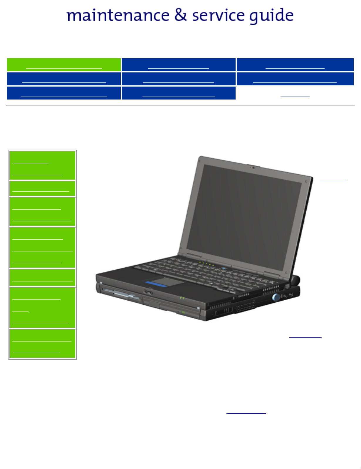
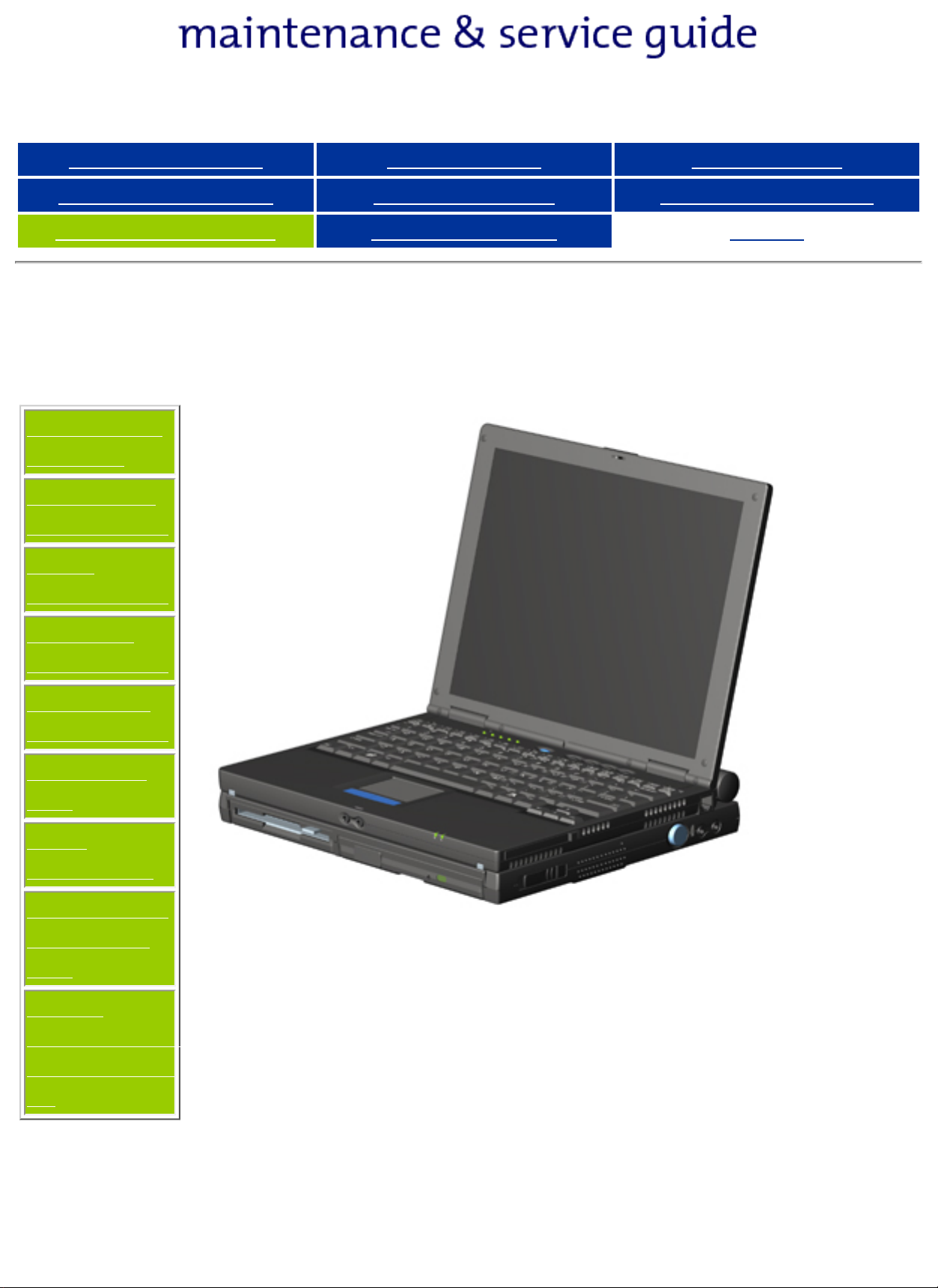
The Compaq
Presario 305
Computer
provides
industryleading
features in a
uniquely
designed
ultraportable.
The ultralight 3.1 to
3.3 pound
(1.4 to 1.5
kg) notebook
(depending
on
configuration)
allows users
high mobility
and provides
a full set of
system ports.
When paired
with the
Mobile
Expansion
Unit (MEU),
the Presario
305 can
transform
into an All-InOne portable
computer
with CD-ROM
or DVD and
floppy
functionality.
Presario 305 Model
Before You Begin Specifications Parts Catalog
Removal Sequence Troubleshooting Battery Operations
Product Description Pin Assignments
Models and Features
Models and
Features
Upper Unit
Components
Front
Components
Left Side
Components
Right Side
Components
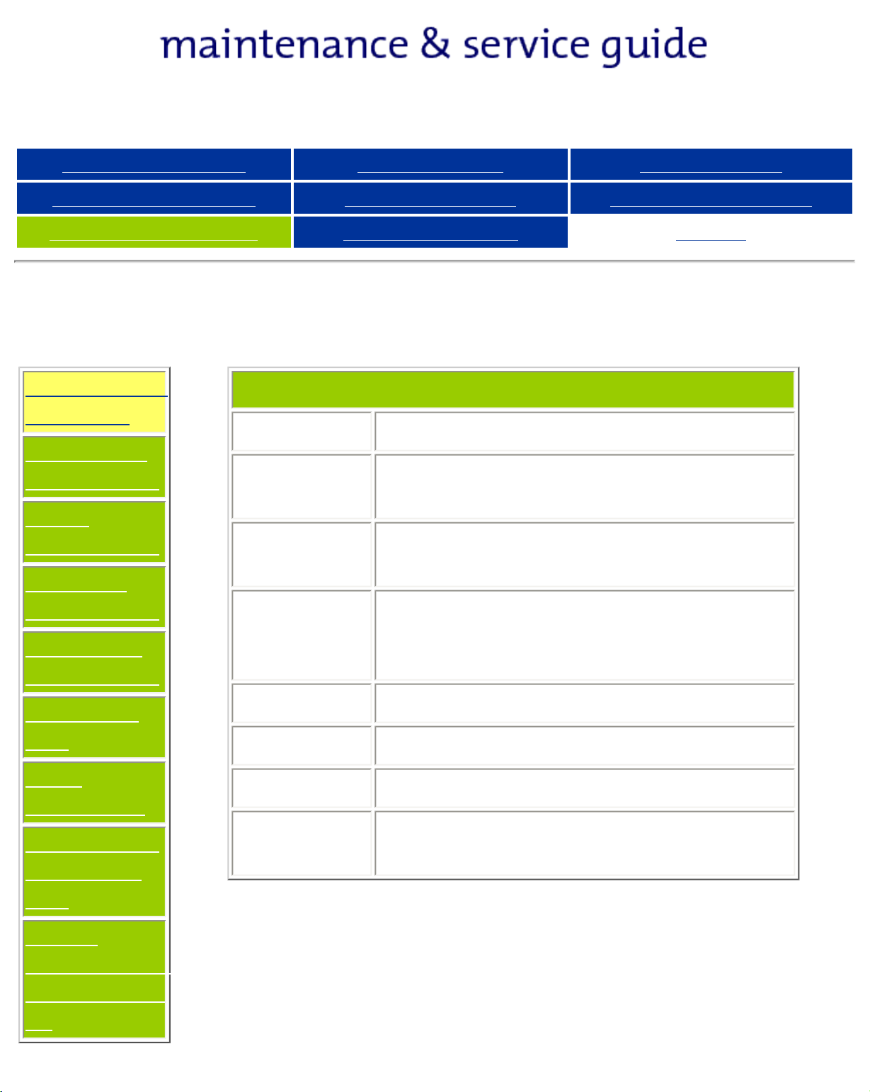
Compaq Presario 305 Model Portable Computer
Display 11.3-inch Color TFT Display
Processor 333 MHz Celeron II (with 128k
integrated cache)
Hard
Drive
Total
System
Memory
4.3 GB
64 MB SDRAM
128 MB SDRAM Maximum
Index
Bottom of
Unit
Rear
Connectors
Multi-media
Expansion
Unit
Power
Management
for Windows
98
CD Drive 24x
Modem 56 Kbps, V.90 PCI
Battery High Capacity Li Ion
Video
Controller
3D, ATI LT Pro 4 MB SGRAM
Presario 305 Model
Before You Begin Specifications Parts Catalog
Removal Sequence Troubleshooting Battery Operations
Product Description Pin Assignments
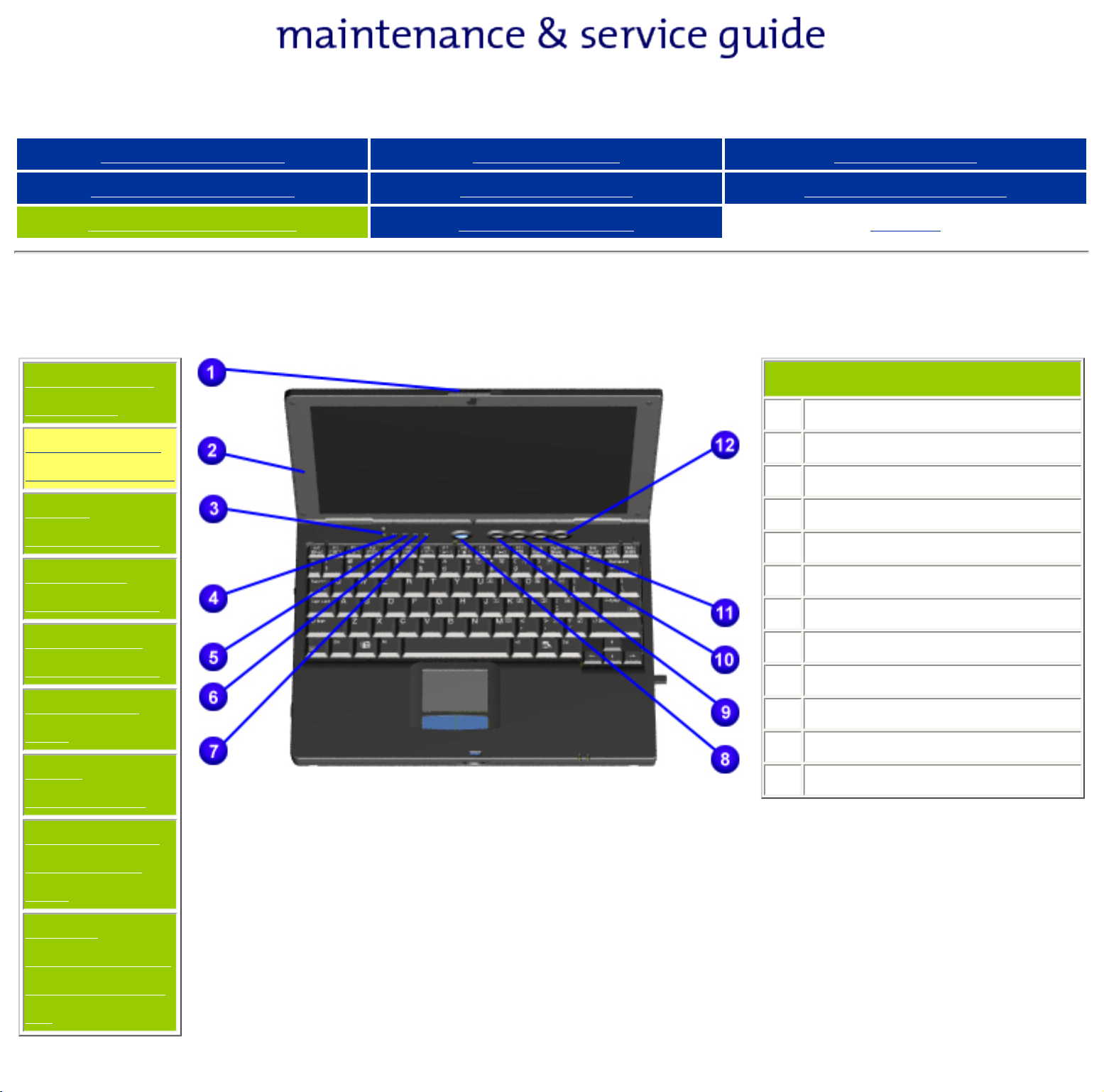
Upper Unit Components
Models and
Features
Upper Unit
Components
Front
Components
Left Side
Components
Index
1
Display Release Latch
2
Display
3
Hard Drive Light
4
Diskette Drive Light
5
Scroll Lock Light
6
Caps Lock Light
7
Num Lock Light
Right Side
Components
Bottom of
Unit
Rear
Connectors
Multi-media
Expansion
Unit
Power
Management
for Windows
98
8
Standby Button
9
Instant Internet Access Button
10
Instant Search Access Button
11
E-Commerce Button
12
Instant E-Mail Button
Presario 305 Model
Before You Begin Specifications Parts Catalog
Removal Sequence Troubleshooting Battery Operations
Product Description Pin Assignments
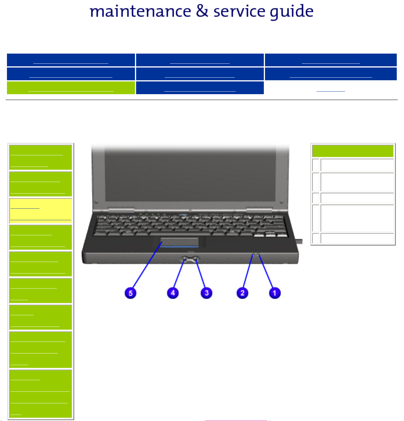
Front Components
Models and
Features
Upper Unit
Components
Front
Components
Left Side
Components
Index
1
Battery Light
2
Power/Suspend
Light
3
Microphone Jack
4
Stereo
Speaker/Headphone
Jack
5
Touch Pad
Right Side
Components
Bottom of
Unit
Rear
Connectors
Multi-media
Expansion
Unit
Power
Management
for Windows
98
Presario 305 Model
Before You Begin Specifications Parts Catalog
Removal Sequence Troubleshooting Battery Operations
Product Description Pin Assignments
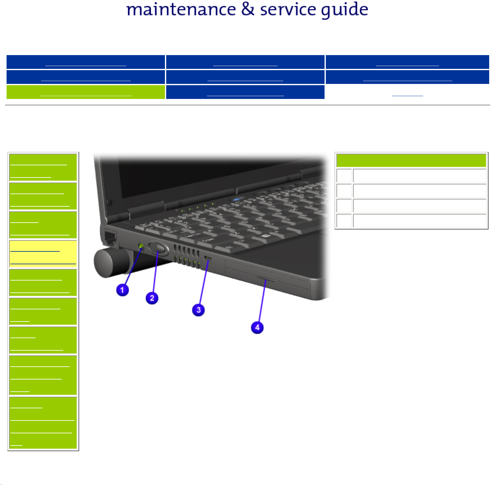
Left Side Components
Models and
Features
Upper Unit
Components
Front
Components
Left Side
Components
Index
1
Power Connector
2
Power Button
3
Security Cable Slot
4
Hard Drive Bay
Right Side
Components
Bottom of
Unit
Rear
Connectors
Multi-media
Expansion
Unit
Power
Management
for Windows
98
Presario 305 Model
Before You Begin Specifications Parts Catalog
Removal Sequence Troubleshooting Battery Operations
Product Description Pin Assignments
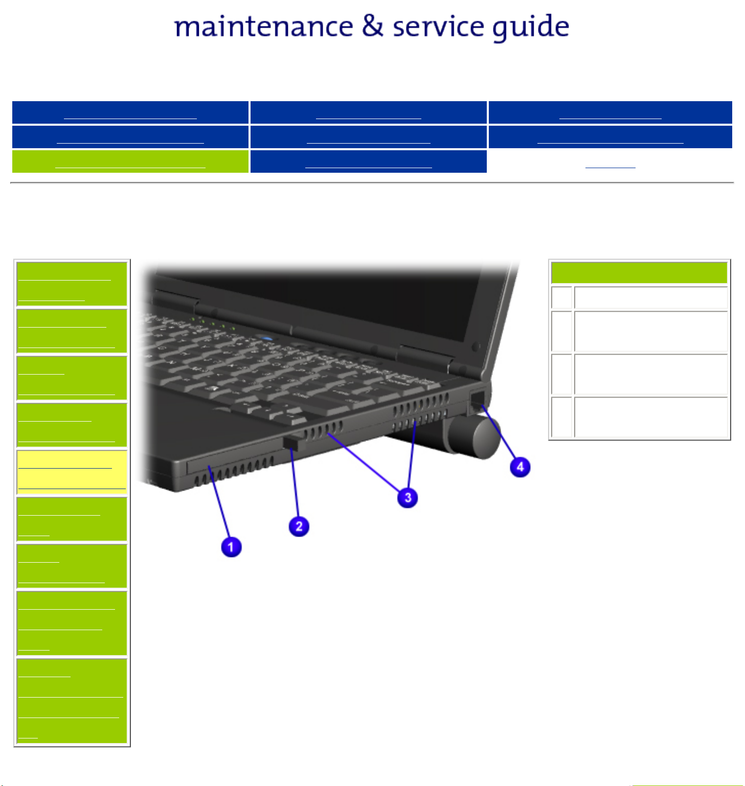
Right Side Components
Models and
Features
Upper Unit
Components
Front
Components
Left Side
Components
Index
1
PC Card Slot
2
PC Card Eject
Lever
3
Air Intake/Exhaust
Vents
4
Modem Connector
(RJ-11 jack)
Right Side
Components
Bottom of
Unit
Rear
Connectors
Multi-media
Expansion
Unit
Power
Management
for Windows
98
Presario 305 Model
Before You Begin Specifications Parts Catalog
Removal Sequence Troubleshooting Battery Operations
Product Description Pin Assignments
Bottom of Unit
Models and
Features
Upper Unit
Components
Front
Components
Left Side
Components
Index
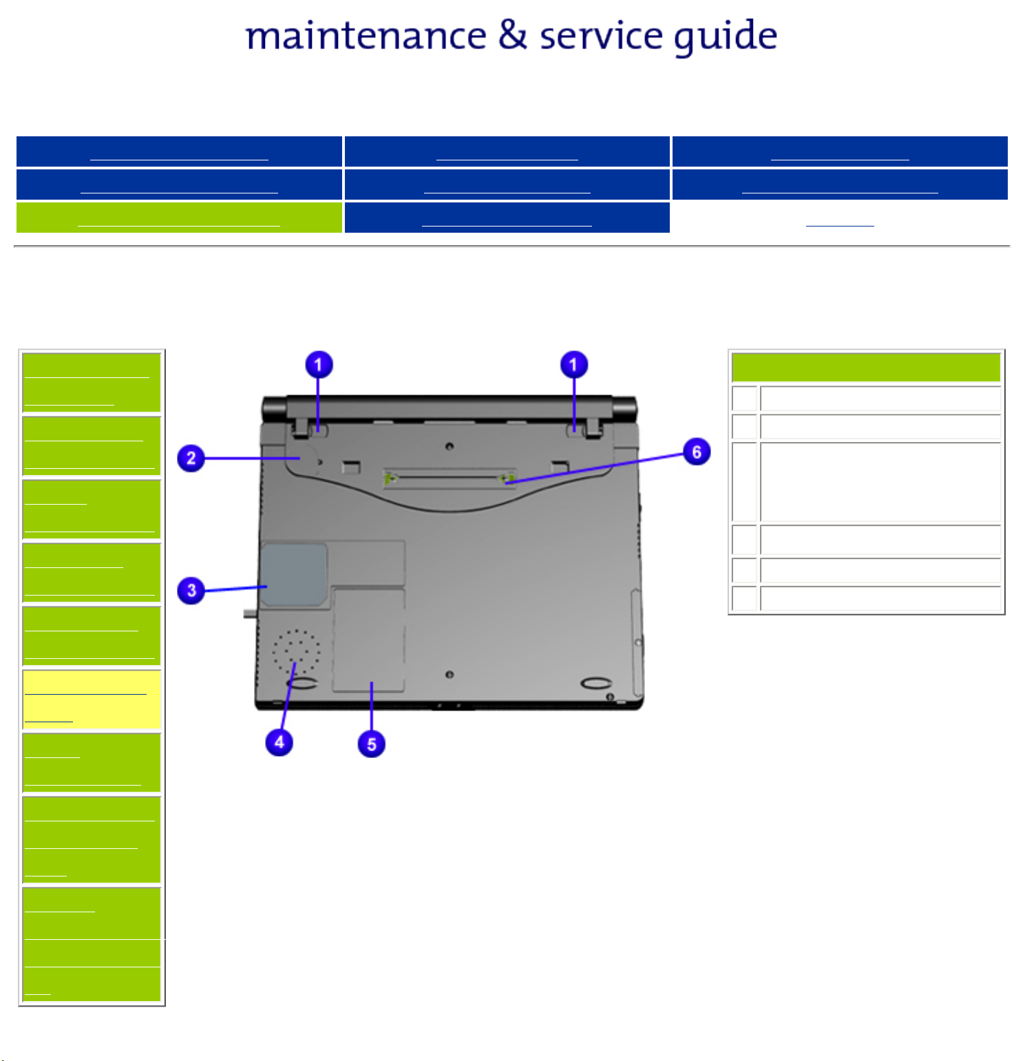
1
Battery Latches
2
Real-time Clock Battery
3
Bottom of fan (Fan
removable from inside
only)
4
Speaker
5
Modem Compartment
6
220-pin Docking Connector
Right Side
Components
Bottom of
Unit
Rear
Connectors
Multi-media
Expansion
Unit
Power
Management
for Windows
98
Presario 305 Model
Before You Begin Specifications Parts Catalog
Removal Sequence Troubleshooting Battery Operations
Product Description Pin Assignments
Rear Connectors
Models and
Features
Upper Unit
Components
Front
Components
Left Side
Components
Index
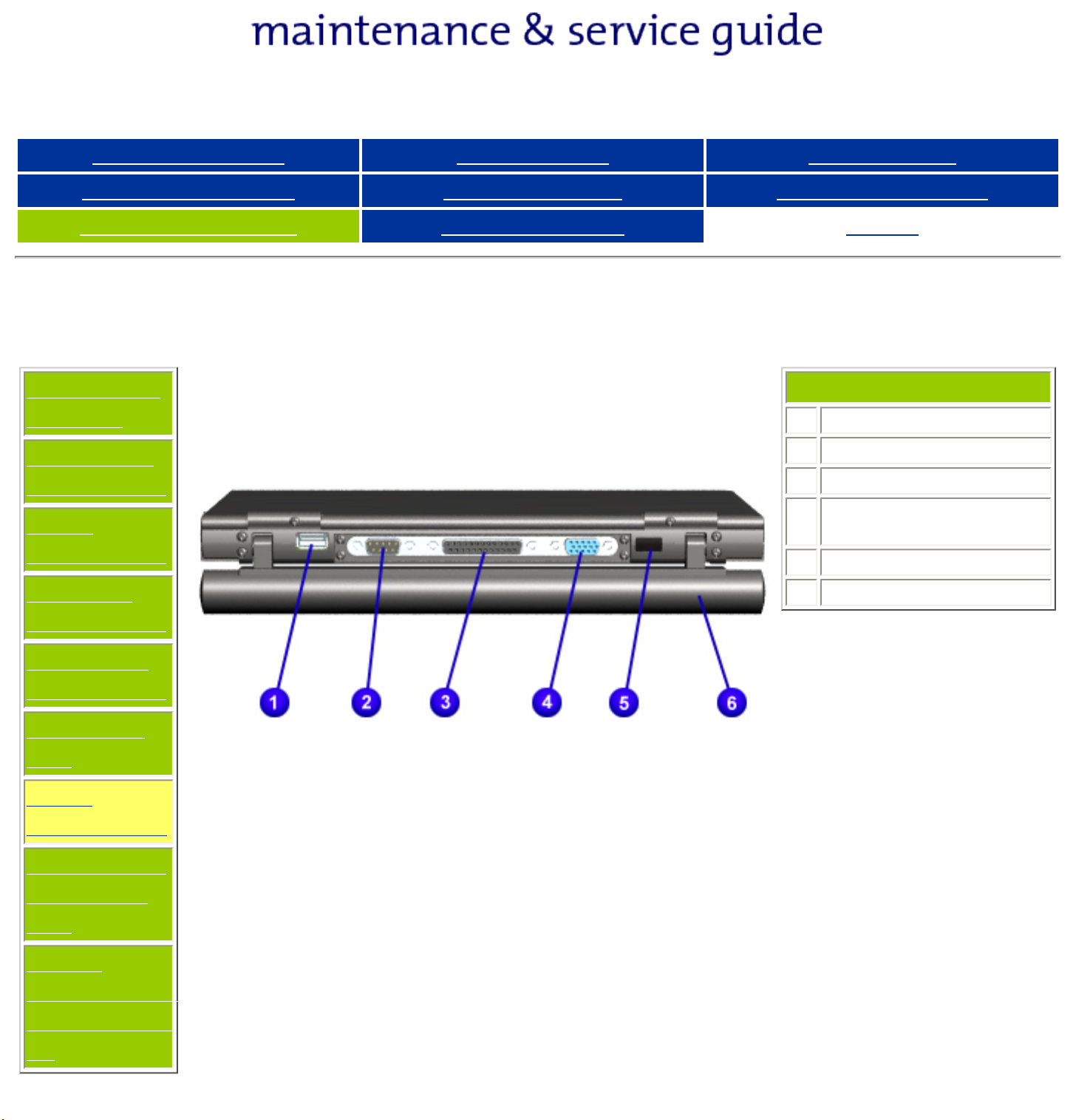
1
USB Connector
2
Serial Connector
3
Parallel Connector
4
External Monitor
Connector
5
Infrared Port
6
Battery Pack
Right Side
Components
Bottom of
Unit
Rear
Connectors
Multi-media
Expansion
Unit
Power
Management
for Windows
98
Presario 305 Model
Before You Begin Specifications Parts Catalog
Removal Sequence Troubleshooting Battery Operations
Product Description Pin Assignments
Multi-media Expansion Base
Models and
Features
Upper Unit
Components
Front
Components
Left Side
Components
Index
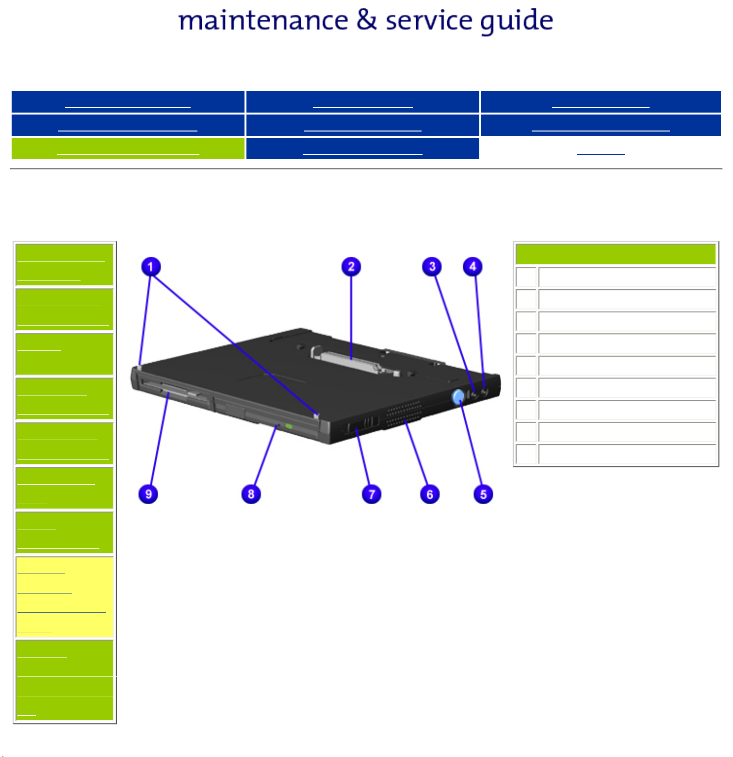
1
Docking Alignment Tabs
2
Docking Connector
3
Audio output
4
Audio input
5
Docking Release Button
6
Speaker
7
Multibay Eject Lever
Right Side
Components
Bottom of
Unit
Rear
Connectors
Multimedia
Expansion
Unit
Power
Management
for Windows
98
8
CD or DVD
9
Diskette Drive

Presario 305 Model
Before You Begin Specifications Parts Catalog
Removal Sequence Troubleshooting Battery Operations
Product Description Pin Assignments
Index
Power Management for Windows 98
The following power management features are available for conserving AC power and extending battery
operating time:
● Power Management Settings
● Sleep
● Hibernation
● Battery operating time
● Rebooting After a Lockup
● Servicing Your Computer - Full Off Mode
Power Management Settings
Depending on your patterns of computer use, you can set different levels of power management. These different
power management levels can be activated based on the amount of time passed since the last system activity.
System activity examples include keyboard or mouse movement, CD or DVD playback (while under program
control that monitors Sleep), and modem use.
Each of the following system components can be made to go to sleep after periods of inactivity:
● system (goes into Sleep (Standby) mode)
● screen (times out and goes blank)
● hard drive (spins down)
You can select different conditions or power schemes through Power Management.The optional settings are
Home/Office Desk, Portable/ Laptop, and Always On. From the default settings, you can change the delay
time settings. Note: the setting for hard drive must be less than or equal to the setting for System.
IMPORTANT:
If you're on a network, it's recommended that you set
System Standby to Never.
There are five categories of power management settings under the Control Panel. The default setting for each
feature is listed below in the tables.
Power Management Properties
Power Schemes:
Always on System Standby:
Turn OFF Monitor
Always on System Standby:
ALARMS:
Low Battery Alarm:
Critical Battery Alarm: 0%
Alarm Actions: X Display Message Notification
Plugged in Running on Batteries
Never 15 minutes
After 15 minutes After 10 minutes
After 15 minutes After 10 minutes
10%
Text Action No Action
POWER METER:
ADVANCED:
Default
Default
Display Properties
Monitor: Laptop Display (Maximum resolution according to unit display size)
Sleep
You can select Sleep mode instead of turning off the computer when you have finished using it. This allows the
computer to wake up faster than turning it completely off and saves power over the active (On) mode. Compaq
Presario Notebook computers have two levels of sleep, Hibernation and Sleep.
Hibernation - by pushing the power button once your computer will perform a save to disk followed by a shut
down of the computer into Off mode.
Sleep - is a low power mode, also referred to as Standby mode. While in Sleep mode, your computer will
maintain system information and open files. Unsaved information will be lost if you turn off your system prior to
system wake-up, or if you lose power while using the AC adapter.
CAUTION: While in Sleep mode, your computer will maintain system information
and open files. Unsaved information will be lost if you turn off your system prior to
system wake-up, or if you lose power while using the AC adapter.
Hibernation Mode
Hibernation helps conserve battery life and protects your data. Hibernation can be a routine power saving event,
or can be the result of a low battery condition. As it enters Hibernation your computer will display a progress
screen, as it automatically saves the machine state before it shuts down and turns itself off. Your computer will
automatically go into Hibernation, when the battery has little power left, or when the system (operating on
battery power) has been in Sleep mode for more than an hour. You can also manually initiate Hibernation by
pressing the power button once while the system is active. To restore the computer's previous state, simply
press the power button once again. While waking up, the computer will display a progress screen.
The following table shows the conditions and indicators for getting in and out of the various power management
modes, Sleep, Hibernation, and Off.
Mode To Initiate To End Indicators
Sleep
Manual keys Standby button Standby
button
Flashing green
Power LED
Time Out Default 15 minutes. If on Battery
power (system will not go to Sleep if on AC
power)
Hibernate
Manual - Slide Power Switch once Slide Power
Switch once
No Power LED,
blank screen
Time Out Default If low battery or after 1 hour
of sleep (system will not Hibernate if on AC
power)
Off Perform normal Windows shutdown via the
start button, or press and hold down the
Slide Power
Switch once
No Power LED,
blank screen
power button for 4 seconds
Servicing Your Computer - Full Off Mode
If you need to install or replace components in your system, you must turn the computer off completely. Follow
the instructions above for properly putting the computer into Off mode, unplug from the outlet, and remove the
battery (see battery section for instructions on removing battery).
Rebooting After a Lockup
Occasionally you may encounter a frozen keyboard or a locked screen. To reboot your computer (as if from a
cold start) slide and hold down the Power Switch for at least four seconds, which will cause a manual shutdown.
Then, restart it with a single slide of the Power Switch. If it still doesn't recover, slide the Power Switch and hold
it for four seconds to shut it down, then, remove the battery or unplug the AC power for at least 30 seconds.
Reinsert the battery or reconnect AC power and slide the Power Switch once to reboot.
Battery Operating Time
Battery operating time is affected by variables, such as the following:
● Power conservation settings
● Hardware configuration
● Software applications
● Installed options
● Display brightness
● Hard drive usage
● Power button
● Changes in operating temperature
● Type and number of installed PC Cards
For more information on increasing battery pack operating time, conditioning the battery pack, and disposing of
a used battery pack, refer to the
Battery Pack Operations.
Compaq Presario Series Maintenance and Service Guide
United States December 9, 2002
Presario 305 Model
Before You Begin Specifications Parts Catalog
Removal Sequence Troubleshooting Battery Operations
Product Description Pin Assignments
Index
Removing the Battery Pack
Removal
Sequence
Serial Number
Location
Preparing for
Disassembly
Electrostatic
Discharge
Service
Considerations
Cables and
Connectors
Multi-media
Expansion
Unit
Battery Pack
Hard Drive
Modem Card
RTC Battery
Keyboard
Memory Board
Switch Cover
Display Panel
Deck
Voltage
Converter
Board
Modem
Connector
Board
PC Card
PC Card
Assembly
System Board
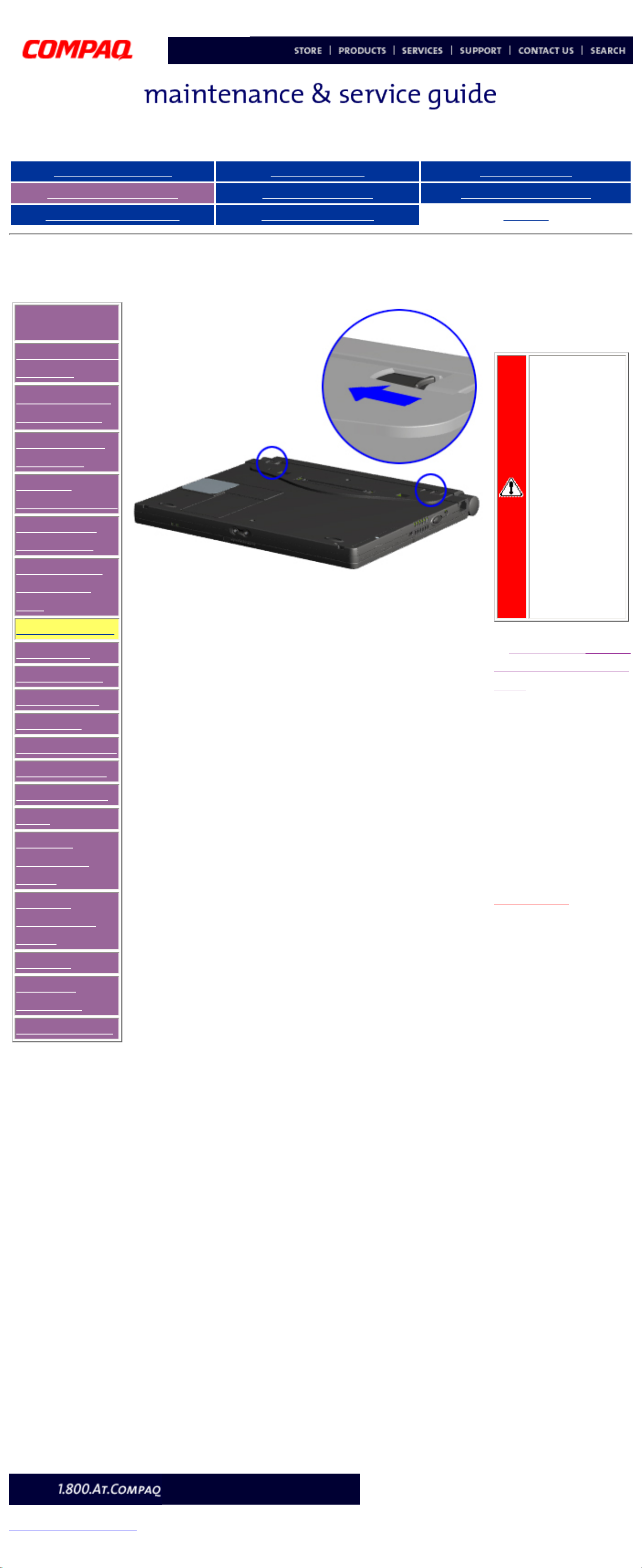
To remove the battery
pack, complete the
following steps:
WARNING:To
reduce the
risk of injury
or damage to
the battery
pack, do not
crush,
puncture, or
incinerate the
battery pack
or short the
metal
contacts. Do
not attempt to
open or
service the
battery pack.
1. Remove the Multi-
media Expansion
Unit.
2. Turn the computer
bottom side up and tilt
the battery pack so it
lies flat (covering all the
ports on the back of the
computer).
3. Slide the two
battery latches
toward the center
of the computer.
Next Step
privacy and legal statement
http://h18000.www1.hp.com/athome/support/msgs/305/battre1.html [12/9/2002 2:16:25 PM]
Compaq Presario Series Maintenance and Service Guide
United States December 9, 2002
Presario 305 Model
Before You Begin Specifications Parts Catalog
Removal Sequence Troubleshooting Battery Operations
Product Description Pin Assignments
Index
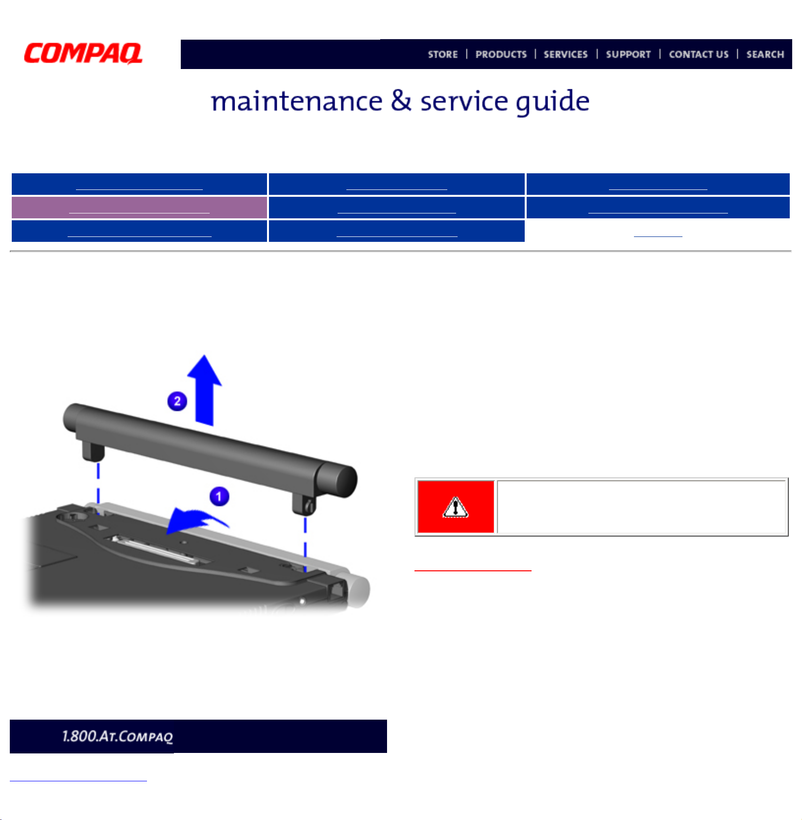
Removing the Battery Pack (continued)
4. Rotate the battery pack into a vertical position 1, and lift up
the battery pack from the computer
2.
To replace the battery pack, reverse the removal
procedures.
WARNING: To prevent damage to the
computer, do not insert a battery pack
until the computer is fully reassembled.
Back to step 1
privacy and legal statement
http://h18000.www1.hp.com/athome/support/msgs/305/battre3.html [12/9/2002 2:16:32 PM]
Compaq Presario Series Maintenance and Service Guide
United States December 9, 2002
Presario 305 Model
Before You Begin Specifications Parts Catalog
Removal Sequence Troubleshooting Battery Operations
Product Description Pin Assignments
Index
Removing the Multi-media Expansion unit
Removal
Sequence
Serial Number
Location
Preparing for
Disassembly
Electrostatic
Discharge
Service
Considerations
Cables and
Connectors
Multi-media
Expansion
Unit
Battery Pack
Hard Drive
Modem Card
RTC Battery
Keyboard
Memory Board
Switch Cover
Display Panel
Deck
Voltage
Converter
Board
Modem
Connector
Board
PC Card
PC Card
Assembly
System Board
To remove
the Multi-
media
Expansion
Unit
,
complete
the
following
steps:
1. Prepare the
computer for
disassembly.
2. Turn off
and
disconnect all
external
devices
connected to
the computer.
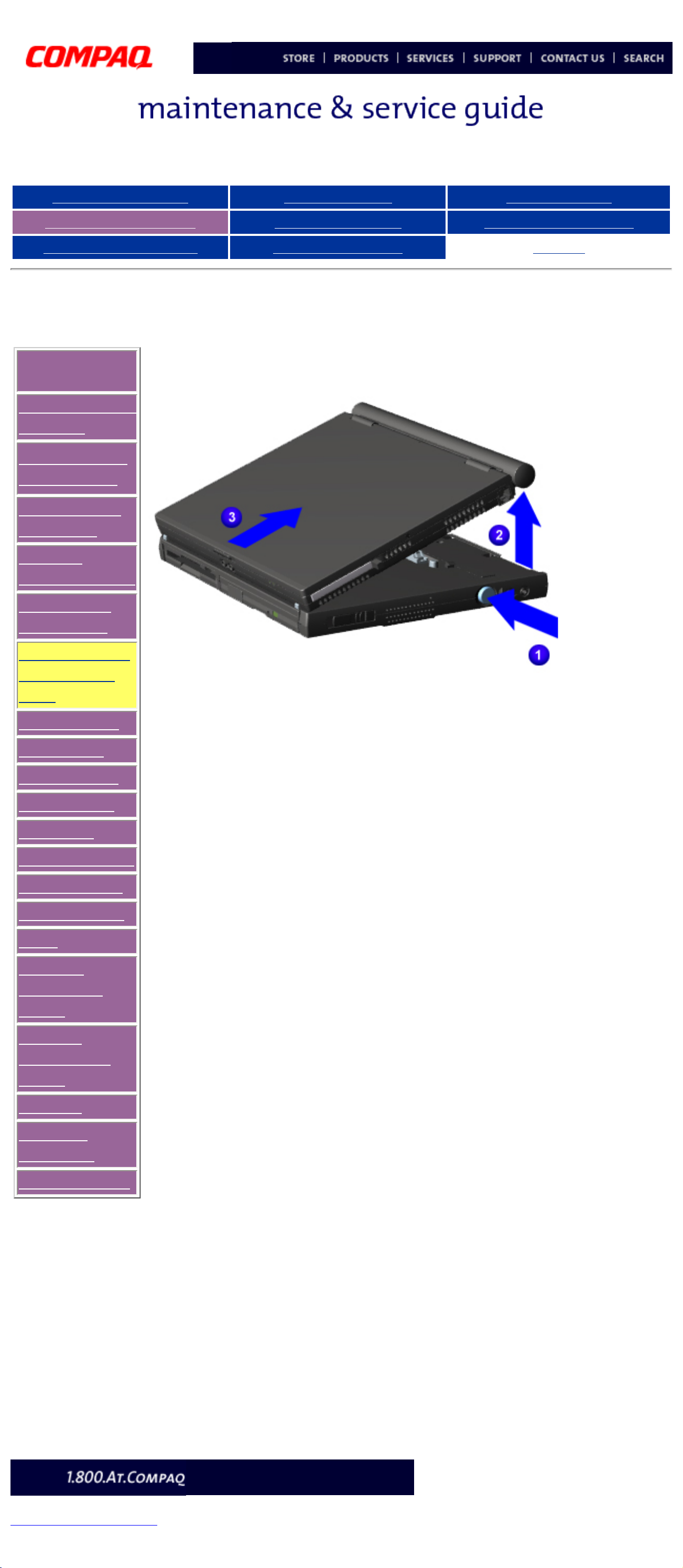
3. On the
Multi-media
Expansion
Unit, press the
docking
release button
1 to release
the expansion
unit from the
computer.
4. Lift the
back end of
the
computer
to
disconnect
it from the
expansion unit
2.
5. Pull the
computer
away from
the
expansion
unit
3.
To replace
the
Multimedia
Expansion
Unit,
reverse the
removal
procedures.
privacy and legal statement
http://h18000.www1.hp.com/athome/support/msgs/305/wedgrem.html [12/9/2002 2:16:36 PM]
Compaq Presario Series Maintenance and Service Guide
United States December 9, 2002
Presario 305 Model
Before You Begin Specifications Parts Catalog
Removal Sequence Troubleshooting Battery Operations
Product Description Pin Assignments
Index
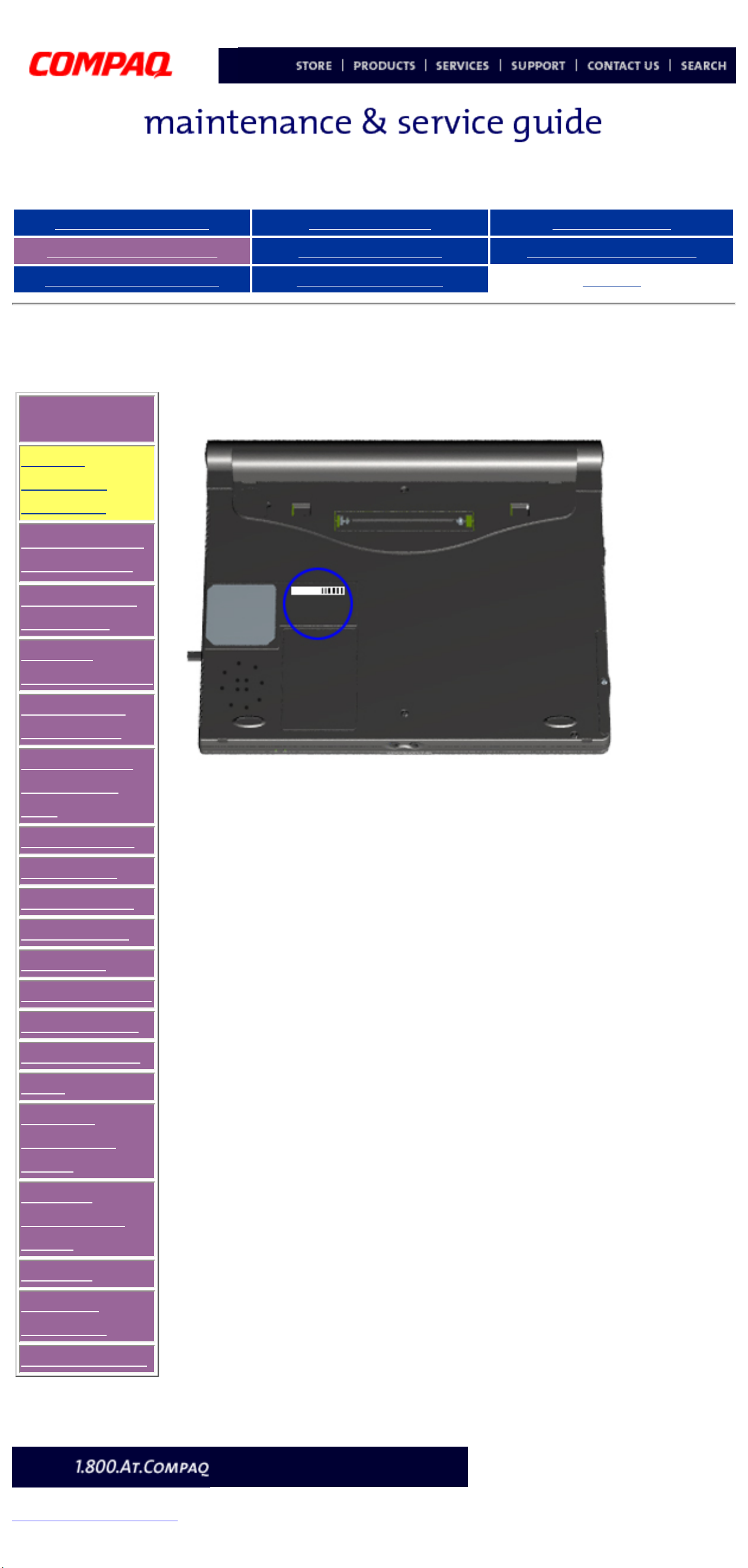
Serial Number Location
Removal
Sequence
Serial
Number
Location
Preparing for
Disassembly
Electrostatic
Discharge
Service
Considerations
Cables and
Connectors
Multi-media
Expansion
Unit
Battery Pack
Hard Drive
Modem Card
RTC Battery
Keyboard
Memory Board
Switch Cover
Display Panel
Deck
Voltage
Converter
Board
Modem
Connector
Board
PC Card
PC Card
Assembly
System Board
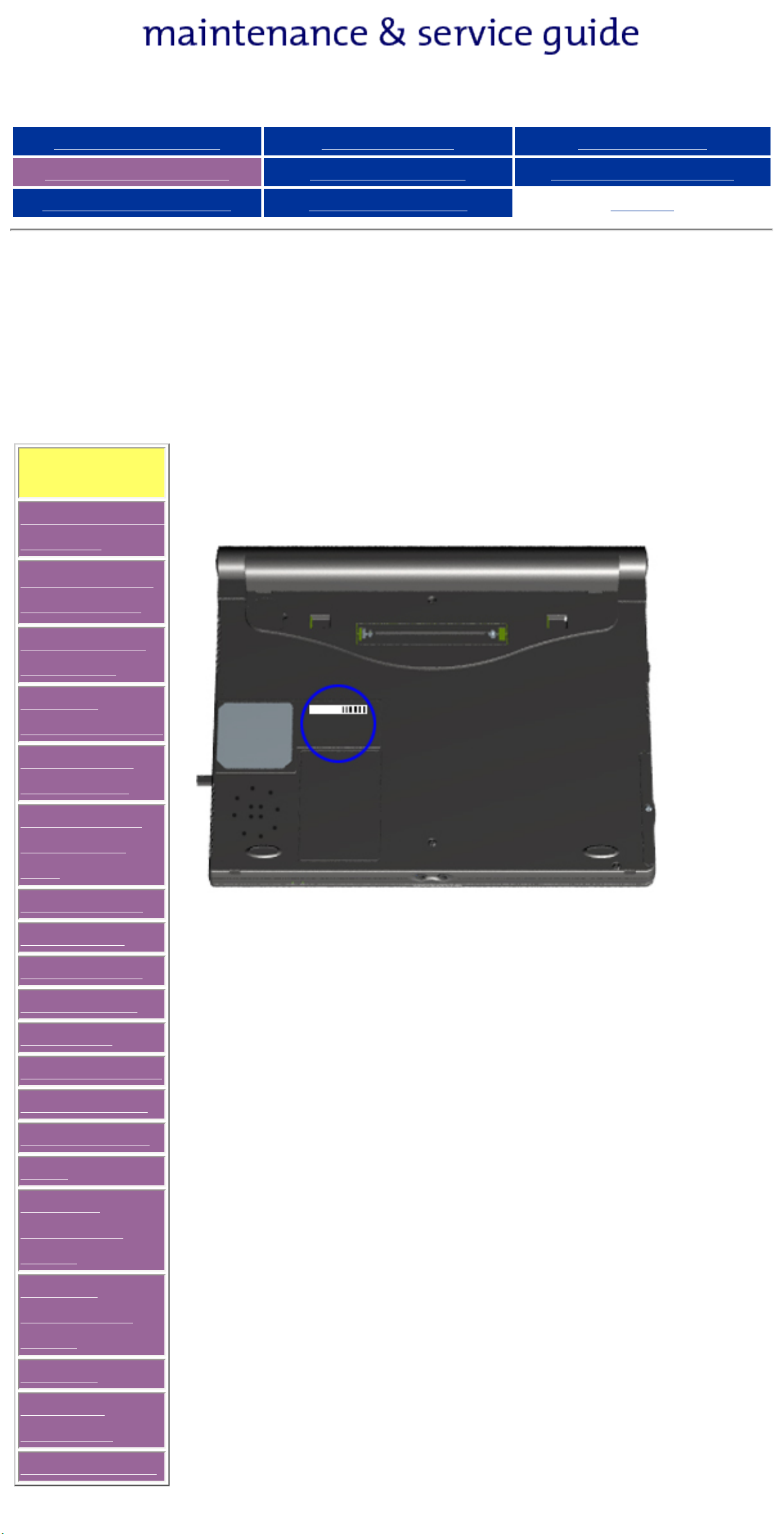
Report the
serial
number to
Compaq
when
requesting
information
on
ordering
spare
parts,
located on
the
underside
of the unit.
privacy and legal statement
http://h18000.www1.hp.com/athome/support/msgs/305/serloc.html [12/9/2002 2:16:42 PM]
Compaq Presario Series Maintenance and Service Guide
United States December 9, 2002
Presario 305 Model
Before You Begin Specifications Parts Catalog
Removal Sequence Troubleshooting Battery Operations
Product Description Pin Assignments
Index
Preparing for Disassembly
Removal
Sequence
Serial Number
Location
Preparing
for
Disassembly
Electrostatic
Discharge
Service
Considerations
Cables and
Connectors
Multi-media
Expansion
Unit
Battery Pack
Hard Drive
Modem Card
RTC Battery
Keyboard
Memory Board
Switch Cover
Display Panel
Deck
Voltage
Converter
Board
Modem
Connector
Board
PC Card
PC Card
Assembly
System Board
Before removing or replacing any components, the following procedures must be
completed:
1. Disconnect AC power and any external devices.
2. Remove the battery pack.
3. Remove any PC Cards.
WARNING: Metal objects can damage the battery pack as well as the
battery contacts in the battery compartment. To prevent damage, do not
allow metal objects to touch the battery contacts. Place only the battery
pack for the Compaq Presario 305 Model Portable Computers into the
battery compartment. Do not force the battery pack into the bay if
insertion does not occur easily.
CAUTION: Do not crush, puncture, or incinerate the battery pack. Do
not open a battery pack, as this damages the pack, makes it unusable,
and exposes potentially harmful battery components. There are no fieldserviceable parts located inside the battery pack.
CAUTION: Failure to disconnect the AC Adapter from the computer and
remove the battery pack before removing and installing internal
components can damage the equipment.
NOTE:
The Compaq Presario 305 Model Portable Computer has several screws
of various sizes which are not interchangeable. Care must be taken
during reassembly to ensure that the correct screws are used in their
appropriate locations. During removal please keep screws with their
associated sub-assembly.
privacy and legal statement
http://h18000.www1.hp.com/athome/support/msgs/305/prepdis.html [12/9/2002 2:16:44 PM]
Compaq Presario Series Maintenance and Service Guide
United States December 9, 2002
Presario 305 Model
Before You Begin Specifications Parts Catalog
Removal Sequence Troubleshooting Battery Operations
Product Description Pin Assignments
Index
Removal and Replacement Procedures
Electrostatic Discharge
A sudden discharge of static electricity from a finger or other conductor can
destroy static-sensitive devices or microcircuitry. Often the spark is neither
felt nor heard, but damage occurs. An electronic device exposed to
electrostatic discharge (ESD) may not be affected at all and will work
perfectly throughout a normal cycle. Although, it may function normally for a
while, then degrade in the internal layers, reducing its life expectancy.
Networks built into many integrated circuits provide some protection, but in
many cases, the discharge contains enough power to alter device parameters
or melt silicon junctions.
Generating Static
The table shows how different activities generate static electricity and at
different electrostatic voltage levels.
Typical Electrostatic Voltages
Relative Humidity
Event 10% 40% 55%
Walking across carpet 35,000 V 15,000 V 7,500 V
Walking across vinyl floor 12,000 V 5,000 V 3,000 V
Motions of bench worker 6,000 V 800 V 400 V
Removing DIPS from plastic tubes 2,000 V 700 V 400 V
Removing DIPS from vinyl trays 11,500 V 4,000 V 2,000 V
Removing DIPS from Styrofoam 14,500 V 5,000 V 3,500 V
Removing bubble pack from PCBs 26,500 V 20,000 V 7,000 V
Packing PCBs in foam-lined box 21,000 V 11,000 V 5,000 V
NOTE: 700 volts can degrade a
product.
Static-Shielding Materials
Material Use Voltage Protection Level
Antistatic Plastic Bags 1,500 V
Carbon-loaded plastic Floor mats 7,500 V
Metallized laminate Floor mats 15,000 V
Return to Removal & Replacement Procedures
privacy and legal statement
http://h18000.www1.hp.com/athome/support/msgs/305/electro.html [12/9/2002 2:16:48 PM]
Presario 305 Model
Before You Begin Specifications Parts Catalog
Removal Sequence Troubleshooting Battery Operations
Product Description Pin Assignments
Index
Removal and Replacement Procedures
This section explains the removal and replacement procedures for the
computer.
Removal
Sequence
Serial Number
Location
Report the computer serial number, located on the bottom of the
unit, when requesting information or ordering spare parts from
Compaq.
Preparing for
Disassembly
Electrostatic
Discharge
Service
Considerations
Cables and
Connectors
Multi-media
Expansion
Unit
Battery Pack
Hard Drive
Modem Card
RTC Battery
Keyboard
Memory Board
Switch Cover
Display Panel
Deck
Voltage
Converter
Board
Modem
Connector
Board
PC Card
PC Card
Assembly
System Board
Presario 305 Model
Before You Begin Specifications Parts Catalog
Removal Sequence Troubleshooting Battery Operations
Product Description Pin Assignments
Index
Service Considerations
Listed below are some of the considerations that you should keep in mind
during the disassembly and reassembly of the computer.
Tool and Software Requirements
To service the computer, you need the following:
● Compaq screwdriver kit
● Torx T-8 screwdriver
● 3/16-inch and 5mm nut drivers (for screwlocks and standoffs)
● Small, standard screwdriver
● Small, Phillips screwdriver
● Diagnostics software
Screws
The screws used in the computer are not interchangeable. If an incorrect
screw is used during the reassembly process, it can damage the unit. Compaq
strongly recommends that all screws removed during disassembly be kept
with the part that was removed, then returned to their proper locations.
Fan and RJ11
The Fan and RJ11 are spared with the base assembly. They are not available
separately, and may only be obtained by ordering the entire base assembly.
This Maintenance and Service Guide contains no removal and replacement
procedures for these components.
As each subassembly is removed from the computer,
IMPORTANT:
it should be placed away from the work area to
prevent damage.
Return to Removal & Replacement Procedures
Presario 305 Model
Before You Begin Specifications Parts Catalog
Removal Sequence Troubleshooting Battery Operations
Product Description Pin Assignments
Index
Cables and Connectors
Most cables used throughout the unit are ribbon cables. Cables must be
handled with extreme care to avoid damage. Apply only the tension required
to seat or unseat the cables during insertion or removal from the connector.
Handle cables by the connector whenever possible. In all cases, avoid
bending, twisting, or tearing the cables, and ensure that the cables are routed
in such a way that they cannot be caught or snagged by parts being removed
or replaced.
Use the following precautions when handling cables to avoid damage to the
cable or computer:
● Always handle cables by their connectors.
● Avoid bending, twisting, or pulling on the cables.
● Apply minimum required force when seating or unseating the cables from
their connectors.
● Place the cables in such a manner that they cannot be caught or snagged by
parts being removed or replaced.
● Handle flex cables with extreme care; they can tear easily.
CAUTION: When servicing these computers, ensure that
cables are placed in their proper location during the
reassembly process. Improper cable placement can cause
severe damage to the unit.
Removing a cable from a ZIF Connector
Display panel cable location
Inverter cable location
Audio cable location
Touchpad cable location
Fan cable location
Light board cable location
Speaker cable location
Battery cable location
Plastic Parts
Plastic parts can be damaged by the use of excessive force during
disassembly and reassembly. When handling the plastic parts, use care. Apply
pressure only at the points designated in the maintenance instructions.
Return to Removal & Replacement Procedures
Maintenance & Service Guide
Presario 305 Model
MSG Index | Home Page | Notice | Preface | Product Description | Troubleshooting
Illustrated Parts Catalog | Removal & Replacement Procedures | Specifications
Pin Assignments | Battery Pack Operations
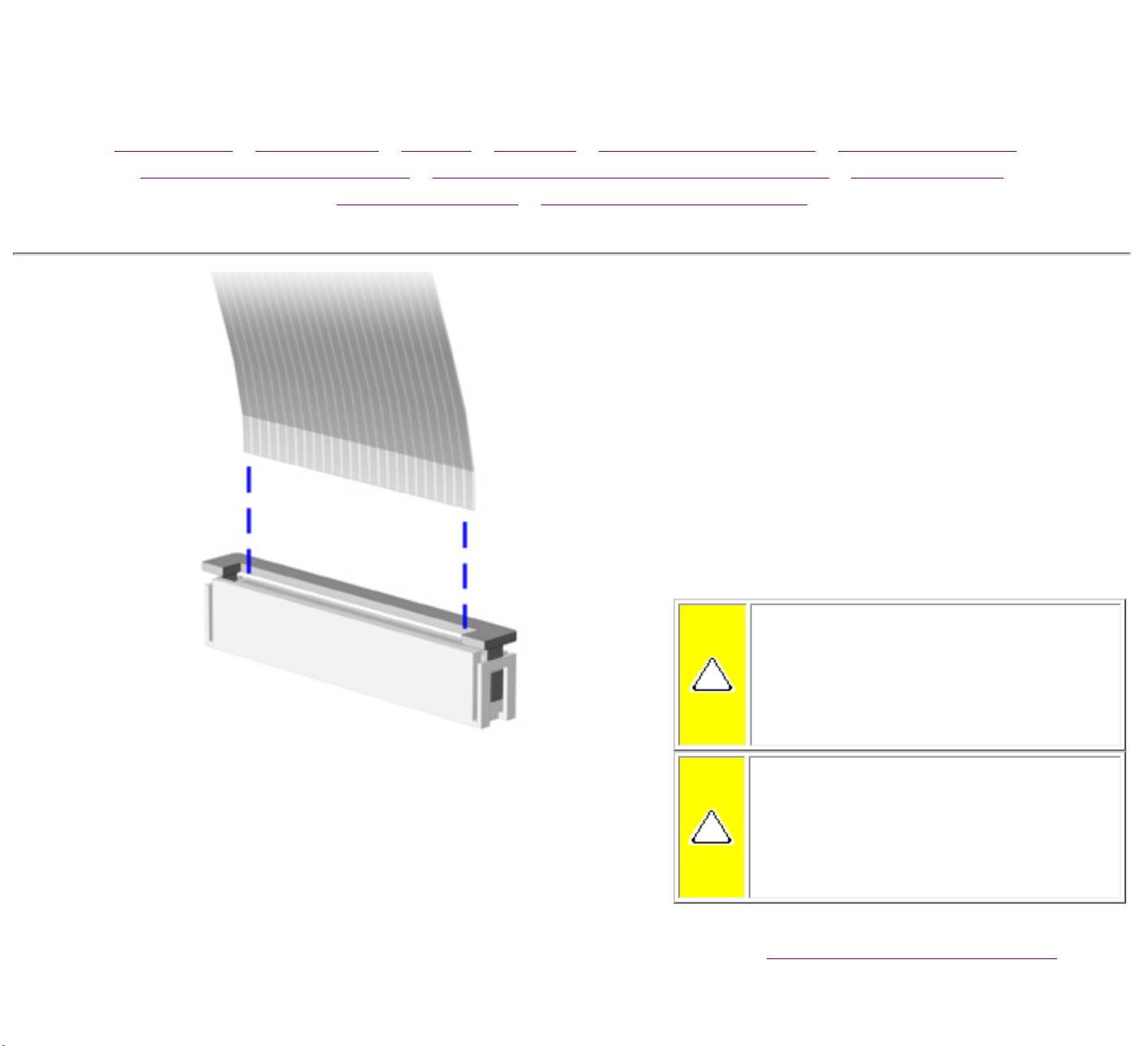
ZIF Connectors
The computer uses a zero insertion
force (ZIF) connector for several cable
connections on the system board. To
remove a ZIF cable from its connector,
pull both ends of the ZIF cable guide
clasp out of the sleeve about 0.05 -
0.1" (1 - 2 mm), then gently slide the
cable out.
CAUTION: A ZIF connector
and its attached cable can be
easily damaged. Never pull or
twist on the cable while it is
connected.
CAUTION: Ensure that cables
are replaced in their proper
location. Improper cable
placement can damage the
computer.
Back to
Cables and Connectors.
Presario 305 Model
Before You Begin Specifications Parts Catalog
Removal Sequence Troubleshooting Battery Operations
Product Description Pin Assignments Index
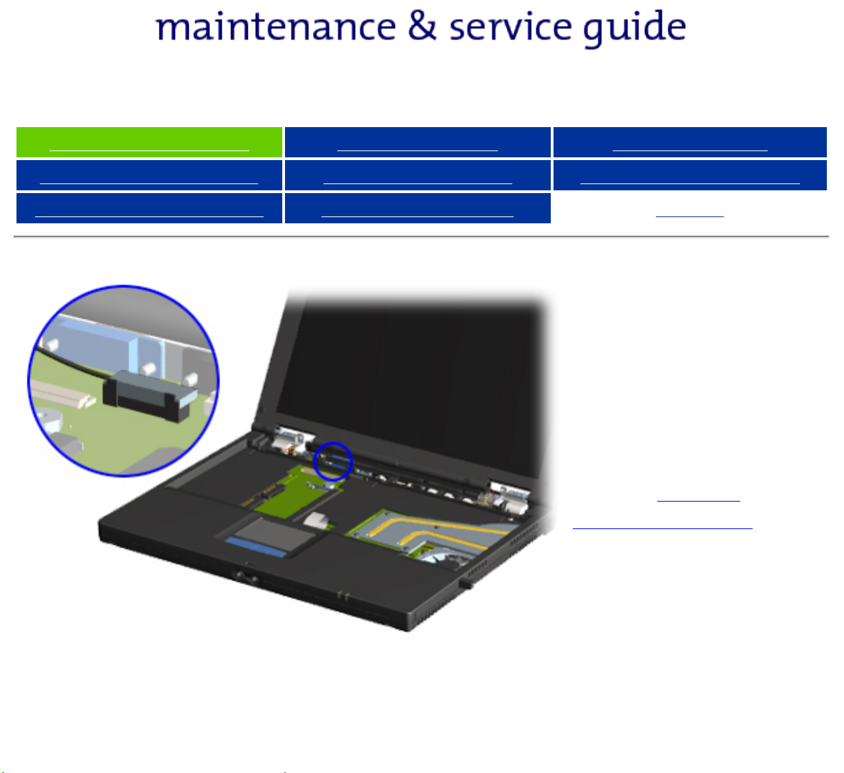
Display Panel
Cable
Location
Note the location of
the display panel
cable.
Back to Cables
and Connectors.
Presario 305 Model
Before You Begin Specifications Parts Catalog
Removal Sequence Troubleshooting Battery Operations
Product Description Pin Assignments Index
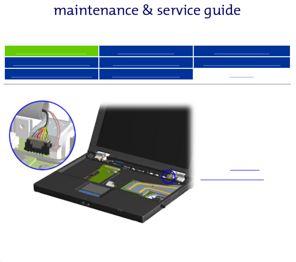
Inverter
Cable
Location
Note the location of
the inverter cable.
Back to Cables
and Connectors.
 Loading...