

HP 303B MT Illustrated Parts & Service Map
Illustrated Parts & Service Map
HP 303B MT Business PC
© 2010 Hewlett-Packard Development Company, L.P. The information con-
tained herein is subject to change without noti ce. HP shall not be liable for
technical or editorial errors or omissions contained herein.
Document Number 630763-001. 1st Edition November 2010.
Key Specifications
Processor Type VIA Nano U2250
RAM Type DDR3-SDRAM DIMMs, PC3-10600 (1333 MHz)
Maximum RAM Supported 4 GB (1 x 4 GB)
Expansion Slots
Graphics Adapter VIA Chrome 9 HD IGP
Chipset VIA VX900
Drive Support • (1) 5.25-inch external optical drive bay
I/O Interfaces Rear: (1) VGA, (1) Serial (2nd serial as option), (1) Parallel,
Operating Systems • Windows 7 Home Basic
Spare Parts
• (1) PCI Express x16
• (1) PCI Express x1
• (2) PCI 2.3
• (1) 3.5-inch internal hard disk drive bay
(1) RJ-45 Ethernet, (2) PS/2, (4) USB 2.0, (3) audio; line in/
rear L&R (blue), line out/front L&R (green), mic (pink)
Front: (2) USB 2.0, (2) audio (mic/headphone), (1) dual-state
power button
• Windows 7 Professional
• RedFlag Linux
• FreeDOS
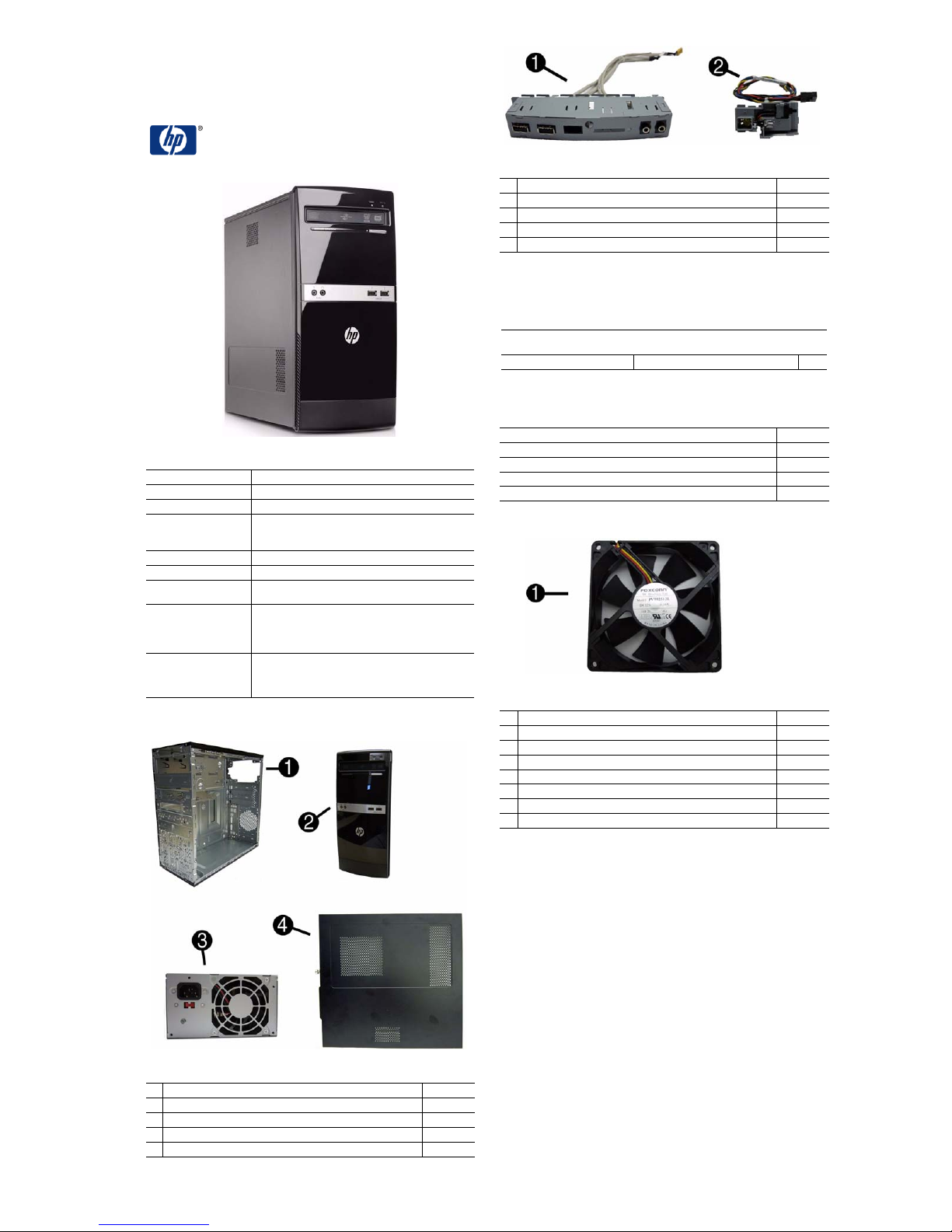
Cables
1 Front I/O assembly without card reader 586729-001
2 Power switch/LED cable assembly 586724-001
* SATA HDD cable, 6.5 inch, with latch 448670-001
* SATA HDD cable 507509-001
* PATA to SATA adapter 449283-001
*Not shown
Keyboards (not illustrated)
HP, PS/2
HP USB, Smartcard
International English -L31 Simplified Chinese -AA1
Mass Storage Devices (not illustrated)
16X DVD±RW SuperMulti drive with LightScribe 581600-001
16X DVD-ROM drive 581599-001
500 GB hard drive 586720-001
320 GB hard drive 586969-001
160 GB hard drive 586718-001
Miscellaneous Parts
1 Chassis fan 449207-001
* Speaker 463316-001
* Mouse, PS2, optical, black 537748-001
* Mouse, USB, laser, black 570580-001
* Mouse, USB, optical, black 537749-001
* Printer port 465339-001
* Serial port, RoHS 392414-001
* Serial port, full height 530599-001
*Not shown
537745-xxx
537747-xxx
System Unit
1 Chassis Not spared
2 Front bezel without card reader 616792-001
3 Power supply, PFC 570028-001
4 Access panel 616791-001
* 5.25-inch bezel blank 586749-001
* Not shown
HP 303B, MT 630763-001 page 1
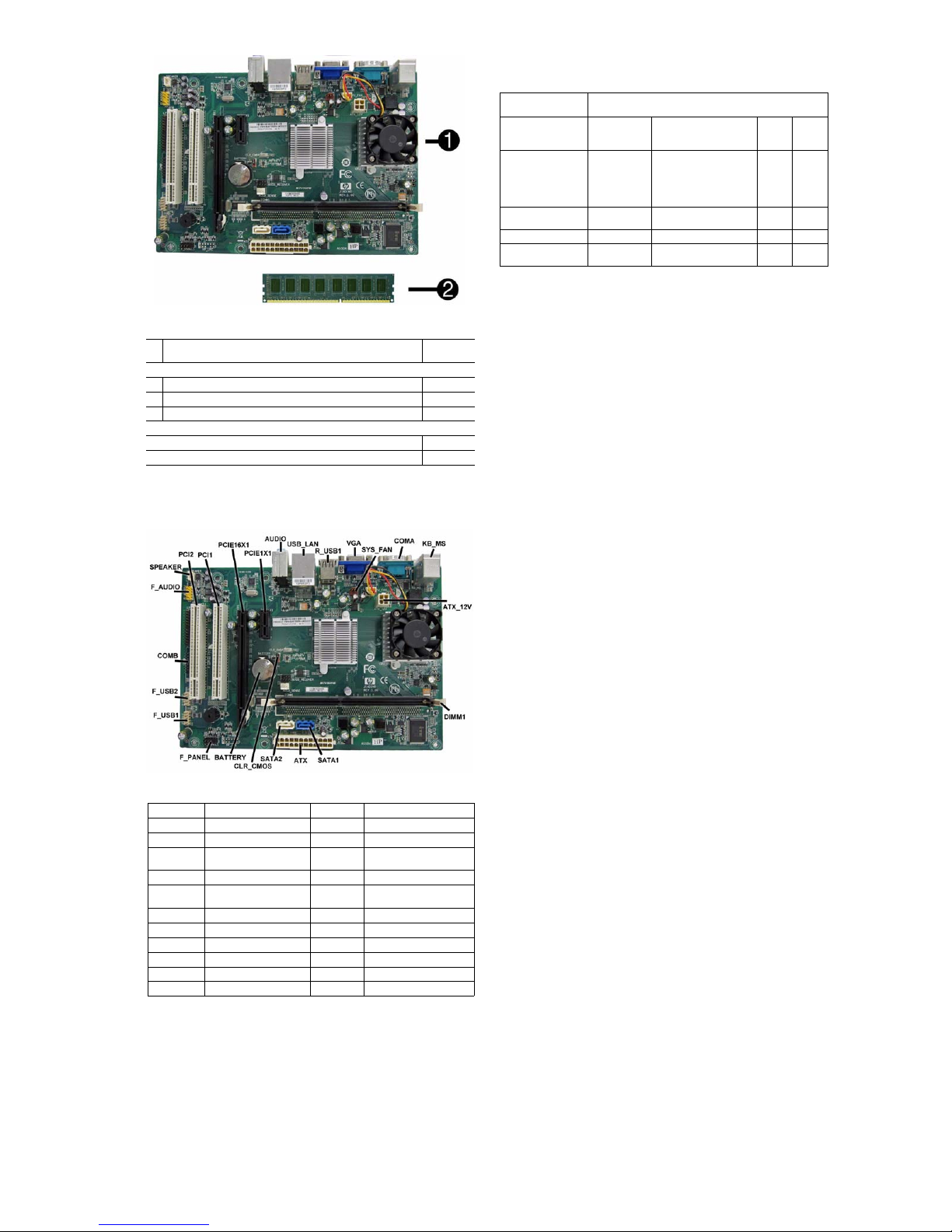
Standard and Optional Boards
1 System board with VIA Nano U2250 processor
(includes thermal material)
Memory modules
* 4 GB, PC3-10600
2 2 GB, PC3-10600
* 1 GB, PC3-10600
Other boards
ATI Radeon HD4350 (RV710) PCIe x16 graphics card, 512 MB 637472-001
GeForce G205, PCIe graphics card, 512MB 589146-001
* Not shown
630089-001
585157-001
576110-001
576109-001
Power States
The following table describes how button presses and generated events are handled in each
power state.
Buttons Pressed or
Events Generated Handling in Each Power State
Power LED Status On With DLED in Type 11:
Num/Caps/Scroll Lock
LEDs (PS/2)
LAN LED (power) On Off Off Off
LAN LED (activity) Blinking - active
On Standby (S1/S3)
Changes color from On (e.g.
green vs. yellow). Otherwise: Blinks using the same
color as in On (e.g. steady-
-- Off Off Off
Off - Otherwise
blue vs. blinking-blue).
Off Off Off
Hibern
ate
(S4)
Off Off
Shut
down
(S5)
Clearing CMOS
The header allows you to clear the RTC RAM in CMOS.
To erase the RTC RAM:
1. Turn off the computer and any external devices, and disconnect power.
2. Remove the access panel.
3. Remove the RTC battery.
4. Locate the CMOS jumper header on the motherboard. It is labeled CLR_CMOS.
5. Remove the jumper from pins 1-2 pins and put it on pins 2-3 to clear CMOS. Keep the cap on
pins 2-3 for 5 to 10 seconds.
6. Replace the jumper on pins 1-2.
7. Reinstall the battery.
8. Replace the access panel, external devices, and reconnect the power cord.
9. Turn on the computer.
10.Hold down the F1 key during boot and enter BIOS setup to re-enter data.
System Board
System Board Connectors and Jumpers (position of some untitled
components may vary in location)
PCI2
PCI1
PCIE16X1
PCIE1X1
AUDI O
USB_LAN
R_USB1
VGA
SYS_FAN
COMA
KB_MS
ATX_12V
PCI slot
PCI slot
PCIe x16 slot
PCIe x1 slot
External in/out connectors
Stacked USB connectors/
Network connector
Stacked USB connectors
Monitor connector
Fan connector
Serial port connector
Keyboard/mouse connectors
4-pin CPU power connector
DIMM1
SATA1
SATA2
ATX
CLR_CMOS
BATTERY
F_PANEL
F_USB1
F_USB2
COMB
F_AUDIO
SPEAKER
Memory slot
Hard drive connector
Optical drive connector
24-pin main power connector
(20-pins used)
Clear CMOS jumper
RTC battery socket
Front I/O connector
Front I/O connector
Front I/O connector
Serial port connector
Front audio connector
Speaker connector
Hewlett-Packard Vision Diagnostics
The Hewlett-Packard Vision Diagnostics utility allows you to view information about the hardware configuration of the computer and perform hardware diagnostic tests on the subsystems of
the computer. The utility simplifies the process of effectively identifying, diagnosing, and isolating hardware issues.
Use HP Vision Diagnostics to determine if all the devices installed on the computer are recognized by the system and functioning properly. Running tests is opt ional but recommended after
installing or connecting a new device.
To access HP Vision Diagnostics, you must create a Recovery Disc Set then boot to the CD containing the utility. It can also be downloaded from http://www.hp.com and either burned to CD
or installed to a USB flash drive.
1. In Windows Explorer, go to C:\SWSetup\ISOs and burn the file Vision Diagnostics.ISO to a
CD or copy it to a USB flash drive.
2. While the computer is on, insert the CD in the optical drive or USB flash drive in a USB port.
3. Shut down the operating system and turn off the computer.
4. Turn on the computer. The system will boot into HP Vision Diagnostics.
NOTE: If the system does not boot to the CD in the optical drive or to the USB flash drive,
you may need to change the boot order in the Computer Setup (F10) utility.
5. At the boot menu, select either the HP Vision Diagnostics utility to t est the various hardware
components in the computer or the HP Memory Test utility to test memory only.
NOTE: The HP Memory Test is a comprehensive memory diagnostic utility that is run as a
stand-alone application, outside of HP Vision Diagnostics.
6. If running HP Vision Diagnostics, select the appropriate language and click Continue.
7. In the End User License Agreement page, select Agree if you agree with th e terms. The HP
Vision Diagnostics utility launches with the Survey tab displayed.
Using the Setup Utility
The BIOS Setup Utility is accessed by pressing the F10 button during startup. The BIOS Setup
Utility allows you to:
• Change factory default settings
• Set the system date and time
• Set, view, change, or verify the system configuration, including settings for graphics, audio,
storage, communications, and input devices
• View processor and memory settings
• Modify the boot order of bootable devices, such as hard drives, diskette drives, optical
drives, or USB media
• Run tests on the hard drive
• Establish a supervisor password that controls access to the Setup Utility
HP 303B, MT 630763-001 page 2
 Loading...