


HP 250 G3 Notebook PC
HP 256 G3 Notebook PC
Maintenance and Service Guide

© Copyright 2015 Hewlett-Packard
Development Company, L.P.
Bluetooth is a trademark owned by its
proprietor and used by Hewlett-Packard
Company under license. Intel, Celeron, Core,
and Pentium are trademarks of Intel
Corporation in the U.S. and other countries.
Microsoft and Windows are U.S. registered
trademarks of the Microsoft group of
companies. SD Logo is a trademark of
its proprietor.
The information contained herein is subject to
change without notice. The only warranties for
HP products and services are set forth in the
express warranty statements accompanying
such products and services. Nothing herein
should be construed as constituting an
additional warranty. HP shall not be liable for
technical or editorial errors or omissions
contained herein.
Second Edition: April 2015
First Edition: August 2014
Document Part Number: 793336-002
Product notice
This guide describes features that are common
to most models. Some features may not be
available on your computer.
Not all features are available on all editions of
Windows 8.1. This computer may require
upgraded and/or separately purchased
hardware, drivers, and/or software to take full
advantage of Windows 8.1 functionality. See
http://www.microsoft.com for details.
This computer may require upgraded and/ or
separately purchased hardware and/or a DVD
drive to install the Windows 7 software and
take full advantage of Windows 7 functionality.
See http://windows.microsoft.com/en-us/
windows7/get-know-windows-7 for details.

Safety warning notice
WARNING! To reduce the possibility of heat-related injuries or of overheating the device, do not place the
device directly on your lap or obstruct the device air vents. Use the device only on a hard, flat surface. Do not
allow another hard surface, such as an adjoining optional printer, or a soft surface, such as pillows or rugs or
clothing, to block airflow. Also, do not allow the AC adapter to contact the skin or a soft surface, such as
pillows or rugs or clothing, during operation. The device and the AC adapter comply with the user-accessible
surface temperature limits defined by the International Standard for Safety of Information Technology
Equipment (IEC 60950).
iii

iv Safety warning notice

Table of contents
1 Product description ....................................................................................................................................... 1
2 External component identification ................................................................................................................. 5
Display ................................................................................................................................................................... 5
Front ....................................................................................................................................................................... 6
Right side ............................................................................................................................................................... 6
Left side ................................................................................................................................................................. 7
Top ......................................................................................................................................................................... 8
TouchPad ............................................................................................................................................. 8
Lights ................................................................................................................................................... 9
Button .................................................................................................................................................. 9
Keys ................................................................................................................................................... 11
Bottom ................................................................................................................................................................. 12
Labels ................................................................................................................................................................... 13
3 Illustrated parts catalog .............................................................................................................................. 15
Computer major components ............................................................................................................................. 15
Miscellaneous parts ............................................................................................................................................. 19
Display assembly subcomponents ..................................................................................................................... 21
Mass storage devices .......................................................................................................................................... 22
Plastics Kit ........................................................................................................................................................... 23
Rubber Kit ............................................................................................................................................................ 23
Sequential part number listing ........................................................................................................................... 24
4 Removal and replacement procedures preliminary requirements .................................................................... 31
Tools required ...................................................................................................................................................... 31
Service considerations ........................................................................................................................................ 31
Plastic parts ....................................................................................................................................... 31
Cables and connectors ...................................................................................................................... 31
Drive handling ................................................................................................................................... 32
Grounding guidelines ........................................................................................................................................... 32
Electrostatic discharge damage ....................................................................................................... 32
Packaging and transporting guidelines ......................................................................... 33
Workstation guidelines ................................................................................ 33
v

5 Removal and replacement procedures for Customer Self-Repair parts ............................................................. 35
Component replacement procedures ................................................................................................................. 35
Battery ............................................................................................................................................... 35
Optical drive ...................................................................................................................................... 37
Keyboard ........................................................................................................................................... 39
6 Removal and replacement procedures for Authorized Service Provider parts ................................................... 43
Component replacement procedures ................................................................................................................. 43
Display subcomponents (bezel, webcam, panel) ............................................................................. 43
Top cover ........................................................................................................................................... 47
Power button board .......................................................................................................................... 50
TouchPad button board .................................................................................................................... 51
Hard drive .......................................................................................................................................... 53
WLAN module .................................................................................................................................... 55
Fan ..................................................................................................................................................... 57
Power connector cable ...................................................................................................................... 59
System board .................................................................................................................................... 60
USB board .......................................................................................................................................... 64
Speakers ............................................................................................................................................ 65
Heat sink assembly ........................................................................................................................... 67
RTC battery ........................................................................................................................................ 70
Memory module ................................................................................................................................ 71
Display assembly .............................................................................................................................. 72
7 Using Setup Utility (BIOS) and HP PC Hardware Diagnostics (UEFI) in Windows 8.1 ............................................ 79
Starting Setup Utility (BIOS) ................................................................................................................................ 79
Updating the BIOS ................................................................................................................................................ 79
Determining the BIOS version ........................................................................................................... 79
Downloading a BIOS update .............................................................................................................. 80
Using HP PC Hardware Diagnostics (UEFI) .......................................................................................................... 80
Downloading HP PC Hardware Diagnostics (UEFI) to a USB device .................................................. 81
8 Using Setup Utility (BIOS) and System Diagnostics in Windows 7 ..................................................................... 83
Starting Setup Utility (BIOS) ................................................................................................................................ 83
Updating the BIOS ................................................................................................................................................ 83
Determining the BIOS version ........................................................................................................... 83
Downloading a BIOS update .............................................................................................................. 84
Using HP PC Hardware Diagnostics (UEFI) .......................................................................................................... 84
Downloading HP PC Hardware Diagnostics (UEFI) to a USB device .................................................. 85
vi

9 Computer Setup (BIOS) and Advanced System Diagnostics in SUSE Linux .......................................................... 87
Starting Computer Setup ..................................................................................................................................... 87
Using Computer Setup ......................................................................................................................................... 87
Navigating and selecting in Computer Setup ................................................................................... 87
Restoring factory settings in Computer Setup ................................................................................. 88
Updating the BIOS ................................................................................................................................................ 88
Determining the BIOS version ........................................................................................................... 88
Downloading a BIOS update .............................................................................................................. 89
Using HP PC Hardware Diagnostics (UEFI) .......................................................................................................... 89
Downloading HP PC Hardware Diagnostics (UEFI) to a USB device .................................................. 90
10 Specifications ........................................................................................................................................... 91
Computer specifications ...................................................................................................................................... 91
39.6-cm (15.6-in) display specifications ............................................................................................................ 92
Hard drive specifications ..................................................................................................................................... 93
DVD±RW SuperMulti DL Drive specifications ...................................................................................................... 94
11 Backing up, restoring, and recovering in Windows 8.1 .................................................................................. 95
Creating recovery media and backups ................................................................................................................ 95
Creating HP Recovery media ............................................................................................................. 95
Restore and recovery .......................................................................................................................................... 96
Recovering using HP Recovery Manager .......................................................................................... 97
What you need to know .................................................................................................. 97
Using the HP Recovery partition (select models only) .................................................. 97
Using HP Recovery media to recover ............................................................................. 98
Changing the computer boot order ................................................................................ 98
Removing the HP Recovery partition (select models only) .............................................................. 98
12 Backing up, restoring, and recovering in Windows 7 ..................................................................................... 99
Creating backups ................................................................................................................................................. 99
Creating recovery media to recover the original system ................................................................. 99
What you need to know .................................................................................................. 99
Creating the recovery media ...................................................................... 100
Creating system restore points ...................................................................................................... 100
What you need to know ................................................................................................ 100
Creating a system restore point ................................................................................... 100
Backing up system and personal information ............................................................................... 100
Tips for a successful backup ........................................................................................ 101
What you need to know ................................................................................................ 101
Creating a backup using Windows Backup and Restore .............................................. 101
vii

Restore and recovery ........................................................................................................................................ 102
Restoring to a previous system restore point ................................................................................ 102
Restoring specific files .................................................................................................................... 102
Restoring specific files using Windows Backup and Restore ...................................... 102
Recovering the original system using HP Recovery Manager ........................................................ 102
What you need to know ................................................................................................ 102
Recovering using HP Recovery partition (select models only) .................................... 103
Recovering using the recovery media .......................................................................... 103
Changing the computer boot order ........................................................... 103
13 Backup and Recovery in SUSE Linux ........................................................................................................... 105
Backing up your information ............................................................................................................................. 105
Performing a system recovery .......................................................................................................................... 105
14 Statement of Volatility ............................................................................................................................ 107
Non-volatile memory usage ............................................................................................................................. 109
Questions and answers ..................................................................................................................................... 111
15 Power cord set requirements .................................................................................................................... 113
Requirements for all countries ......................................................................................................................... 113
Requirements for specific countries and regions ............................................................................................. 114
16 Recycling ................................................................................................................................................ 117
Battery ............................................................................................................................................................... 117
Display ............................................................................................................................................................... 117
Index ........................................................................................................................................................... 123
viii

1 Product description
Category Description
Product name HP 250 G3 Notebook PC
HP 256 G3 Notebook PC (for China)
Processors 5th generation IntelR Core processors
IntelR Core i5 processor (EMEA only)
IntelR Core i3 processor (EMEA only)
4th generation Intel Core i processors
Intel Core i5-4210U processor (1.7-GHz, 3-MB L2 cache, 1600-MHz)
Intel Core i3-4030U processor (1.9-GHz, 3-MB L2 cache, 1600-MHz)
Intel Core i3-4010U processor (1.7-GHz, 3-MB L2 cache, 1600-MHz)
Intel Core i3-4005U processor (1.7-GHz, 3-MB L2 cache, 1600-MHz)
3rd generation Intel Core-i processor
Intel Core i3-3217U processor (1.8-GHz, 3-MB L2 cache, 1600-MHz)
Intel Bay Trail M processors
Intel Pentium N3540 processor (2.16-GHz [turbo up to 2.66 GHz], 2-MB L2 cache, 1333-MHz)
Intel Pentium N3530 processor (2.58-GHz, 2-MB L2 cache, 1333-MHz)
Intel Pentium N3520 processor (2.17-GHz [turbo up to 2.42 GHz], 2-MB L2 cache, 1333-MHz)
Intel Celeron N2840 processor (2.16-GHz [turbo up to 2.58 GHz], 1-MB L2 cache, 1333-MHz)
Intel Celeron N2830 processor (2.41-GHz, 1-MB L2 cache, 1333-MHz)
Intel Celeron N2920 processor (1.86-GHz [turbo up to 2.0 GHz], 2-MB L2 cache, 1066-MHz)
Intel Celeron N2820 processor (2.13-GHz [turbo up to 2.4 GHz], 2-MB L2 cache, 1066-MHz)
Intel Celeron N2815 processor (1.86-GHz [turbo up to 2.13 GHz], 1-MB L2 cache, 1066-MHz)
Intel Celeron N2805 processor (1.46-GHz, 2-MB L2 cache, 1066-MHz)
Chipset Intel Shark Bay ULT One Chip Solution
Intel Lynx Point-LP PCH (Integrated in MCP)
Intel HM76 Express Chipset
Intel Bay Trial-M SoC
Graphics Internal graphics:
Intel HD Graphics 4400 (4th generation Intel processors)
Intel HD Graphics 4000 (3rd generation Intel processors)
Intel HD Graphics (Intel Bay Trail-M processors)
Switchable discrete (external) graphics:
Nvidia 820M N15V-GM 1 GB VRAM
1

Category Description
Nvidia 820M N15V-GM 2 GB VRAM (4th generation Intel processors)
GPU power management enabled at launch
Support DX11
Support dynamic switching
Support HD Decode and HDMI
Panel 39.6-cm (15.6-in), high-definition (HD), light-emitting diode (LED), SVA Anti-Glare (1366×768) display, flat
3.8 mm; typical brightness: 200 nits
39.6-cm (15.6-in), high-definition (HD), light-emitting diode (LED), SVA BrightView (1366×768) display,
slim 3.2 mm; typical brightness: 200 nits (for touch solution only)
Touch screen is multi-touch enabled
Supports LVDS
Memory
Hard drives Supports 6.35-cm (2.5-in) hard drives in 9.5-mm (.37-in) and 7.0-mm (.28-in) thicknesses
1 or 2 customer-accessible/upgradable memory module slots (depending on model)
DDR3L-1600-MHz Dual Channel Support
DDR3L-1333-MHz Dual Channel Support (DDR3-1600 downgrade to DDR3-1333)
DDR3L-1066-MHz Dual Channel Support (DDR3-1600 downgrade to DDR3-1066)
Supports up to 8 GB of system RAM in the following configurations:
●
8192-MB total system memory (8192×1) or (4096×2)
●
6144-MB total system memory (4096×1 + 2048×1)
●
4096-MB total system memory (4096×1) or (2048×2)
●
2048-MB total system memory (2048×1)
Serial ATA
Supports the following hard drives:
●
1-TB, 5400-rpm, 9.5-mm
●
750-GB, 5400-rpm, 9.5-mm
●
500-GB, 7200-rpm, 7.0-mm
●
500-GB, 5400-rpm, 9.5-mm or 7.0-mm
●
320-GB, 5400-rpm, 9.5-mm or 7.0-mm
Optical drive Fixed, serial ATA, 9.5-mm tray load
Audio/video Single digital microphone
Ethernet Integrated 10/100 network interface card (NIC)
2 Chapter 1 Product description
DVD+/-RW Double-Layer SuperMulti
Supports zero power optical drive
Supports weight saver in optical drive bay
HD audio, dual speakers
HP TrueVision HD camera (fixed, no tilt with activity LED, 1280×720 by 30 frames per second)
Integrated 10/100/1000 network interface card (NIC) (UMA, non-touch models only)

Category Description
Wireless Integrated wireless local area network (WLAN) options by way of wireless module
One or two WLAN antennas built into display assembly
Compatible with Miracast-certified devices (Windows 8.1; not for models with Intel Pentium or Celeron
processors)
Single antenna support
Support for the following WLAN formats:
●
Realtek RTL8188EE 802.11bgn 1x1 Wi-Fi Adapter
●
Qualcomm Atheros AR9485 802.11bgn 1x1 Wi-Fi Adapter
●
Ralink RT3290LE 802.11bgn 1x1 Wi-Fi + BT 4.0 Combo Adapter
●
QCA 9565 802.11bgn 1x1 Wi-Fi + BT4.0 Combo Adapter
External media card HP Multi-Format Digital Media Reader
Support SD/SDHC/SDXC
Push-Pull Insertion/Removal
Ports VGA (Dsub 15 pin) supporting 2048 × 1536 external resolution @ 75Hz
HDMI version 1.4 supporting 1920 ×1200 @ 60Hz
Hot Plug/unplug and auto detect for correct output to wide-aspect vs. standard aspect video
RJ-45 (Ethernet, includes link and activity lights)
USB 3.0 (1 port)
USB 2.0 (2 ports)
AC Smart Pin adapter plug
Headphone/microphone in combo jack
Keyboard/pointing
devices
Power requirements AC adapters:
Batteries:
Full-size textured "island style" keyboard with numeric keypad
TouchPad with multi-touch gestures, 2-finger scrolling, and pinch-zoom enabled
Taps enabled by default
Support Win8.1+D212 Modern Trackpad Gestures
Support PS/2, profile sensor (reserve for SMBus)
AC Adapter 65-W Smart nPFC, 3 pin, RC 4.5mm connector - non slim for use in discrete models
AC Adapter 45-W Smart nPFC, 3 pin, RC 4.5mm connector - non slim for use in UMA models
AC Adapter 65-W EM Smart nPFC, 3 pin, RC 4.5mm connector, 90 degree plug design for use in India/China
1 meter power cord
4-cell, 41-Whr Li-ion battery
3-cell, 31-Whr Li-ion battery
Security Kensington Security Lock
Support Intel Anti-Theft
Support Intel IPT
3

Category Description
OTP support
Operating system Preinstalled:
●
Windows 8.1
●
Windows 8.1 (CPPP) –China only
●
Windows 8.1 Pro for Education
●
Windows 7 (Windows 8.1 Downgrade)
●
Windows 7 Home Basic
●
Ubuntu
●
FreeDOS 2.0
Serviceability End-user replaceable parts:
●
AC adapter
●
Battery
●
Optical drive
●
Keyboard
4 Chapter 1 Product description
2 External component identification
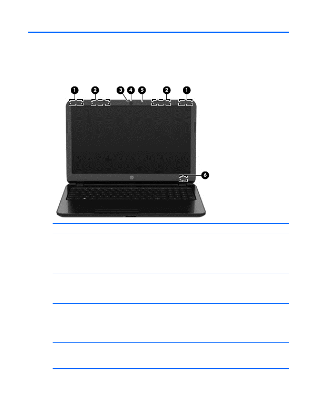
Display
Component Description
(1) WLAN antennas (1 or 2)* (select models only) Send and receive wireless signals to communicate with wireless local
(2) WWAN antennas (1 or 2)* (select models only) Send and receive wireless signals to communicate with wireless wide
(3) Webcam light On: The webcam is in use.
(4) Webcam Records video and captures photographs. Some models allow you to
(5) Internal microphone Records sound.
(6) Internal display switch Turns off the display and initiates Sleep if the display is closed while
*The antennas are not visible from the outside of the computer. For optimal transmission, keep the areas immediately around the
antennas free from obstructions. For wireless regulatory notices, see the section of the Regulatory, Safety, and Environmental Notices
that applies to your country or region. To access this guide in Windows 8.1, from the Start screen, type support, and then select the
HP Support Assistant app.
area networks (WLANs).
area networks (WWAN).
video conference and chat online using streaming video.
To use the webcam in Windows 8.1, from the Start screen, type
camera, and then select Camera from the list of applications.
the power is on.
NOTE: The internal display switch is not visible from the outside of
the computer.
Display 5
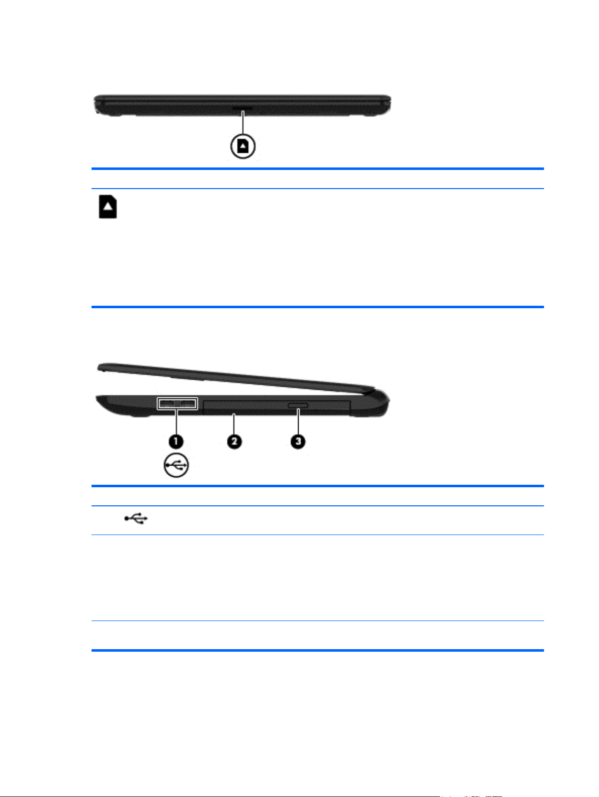
Front
Component Description
Right side
Memory card reader Reads optional memory cards that store, manage,
share, or access information.
To insert a card:
Hold the card label-side up, with connectors facing the
slot, insert the card into the slot, and then push in on the
card until it is firmly seated.
To remove a card:
Pull the card out of the slot.
Component Description
(1)
(2) Optical drive (select models only) Depending on your computer model, reads an optical
(3) Optical drive eject button (select models
USB 2.0 ports (2) Connect an optional USB device, such as a keyboard,
only)
6 Chapter 2 External component identification
mouse, external drive, printer, scanner or USB hub.
disc or reads and writes to an optical disc.
NOTE: For disc compatibility information, go to the
Help and Support web page. Follow the web page
instructions to select your computer model. Select
Support & Drivers, and then select Product
Information.
Releases the disc tray.
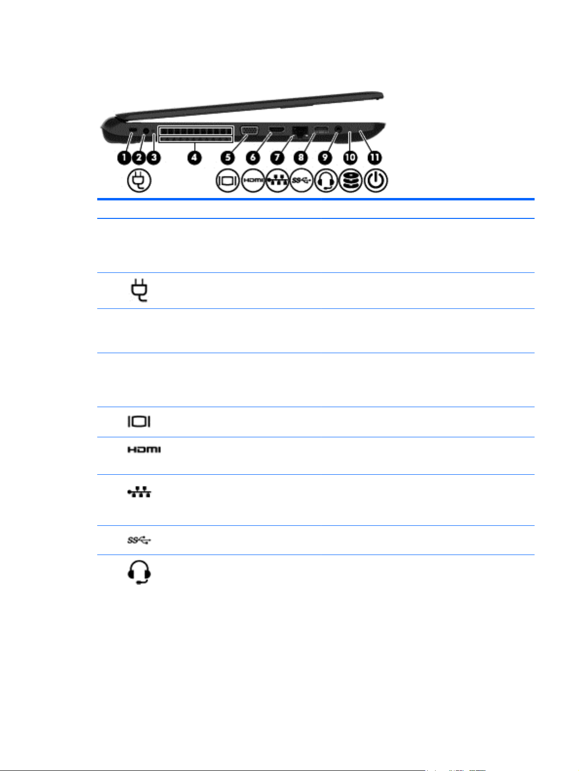
Left side
Component Description
(1) Security cable slot Attaches an optional security cable to the computer.
NOTE: The security cable is designed to act as a deterrent, but
it may not prevent the computer from being mishandled or
stolen.
(2)
(3) AC adapter light
(4) Vent Enables airflow to cool internal components.
(5)
(6)
(7)
(8)
(9)
Power connector Connects an AC adapter.
●
On: The AC adapter is connected and the battery is
charged.
●
Off: The computer is using battery power.
NOTE: The computer fan starts up automatically to cool
internal components and prevent overheating. It is normal for
the internal fan to cycle on and off during routine operation.
External monitor port (select models only) Connects an external VGA monitor or projector.
HDMI port Connects an optional video or audio device, such as a high-
RJ-45 (network) jack/status lights Connects a network cable.
USB 3.0 port Connects an optional USB device, such as a keyboard, mouse,
Audio-out (headphone)/Audio-in (microphone)
jack
definition television, any compatible digital or audio
component, or a high-speed HDMI device.
●
White: The network is connected.
●
Amber: Activity is occurring on the network.
external drive, printer, scanner or USB hub.
Connects optional powered stereo speakers, headphones,
earbuds, a headset, or a television audio cable. Also connects an
optional headset microphone. This jack does not support
optional microphone-only devices.
WARNING! To reduce the risk of personal injury, adjust the
volume before putting on headphones, earbuds, or a headset.
For additional safety information, refer to the Regulatory,
Safety, and Environmental Notices. To access this guide in
Windows 8.1, from the Start screen, type support, and then
select the HP Support Assistant app.
NOTE: When a device is connected to the jack, the computer
speakers are disabled.
Left side 7
Component Description
NOTE: Be sure that the device cable has a 4-conductor
connector that supports both audio-out (headphone) and audioin (microphone).
(10)
(11)
Top
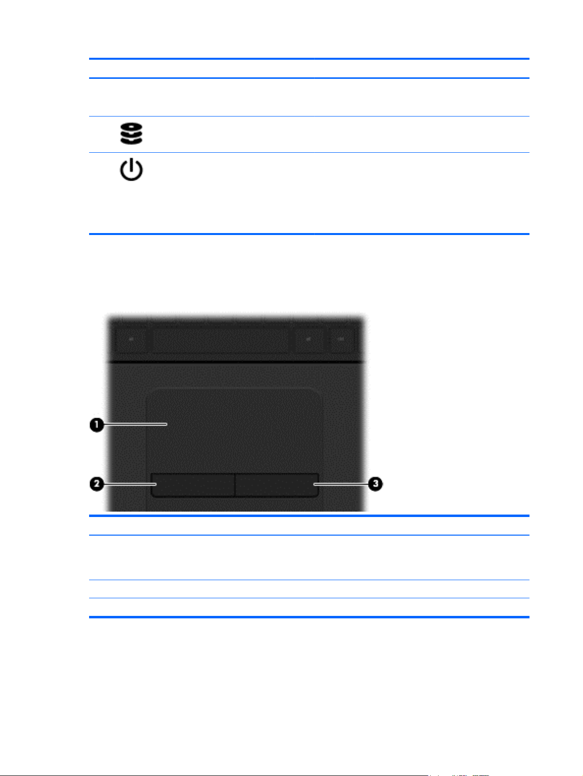
TouchPad
Hard drive light Blinking white: The hard drive is being accessed.
Power light
●
On: The computer is on.
●
Blinking: The computer is in the Sleep state, a powersaving state. The computer shuts off power to the display
and other unneeded components.
●
Off: The computer is off or in Hibernation. Hibernation is a
power-saving state that uses the least amount of power.
Component Description
(1) TouchPad zone Moves the on-screen pointer and selects or activates items on
(2) Left TouchPad button Functions like the left button on an external mouse.
(3) Right TouchPad button Functions like the right button on an external mouse.
8 Chapter 2 External component identification
the screen.
NOTE: The TouchPad also supports edge-swipe gestures.
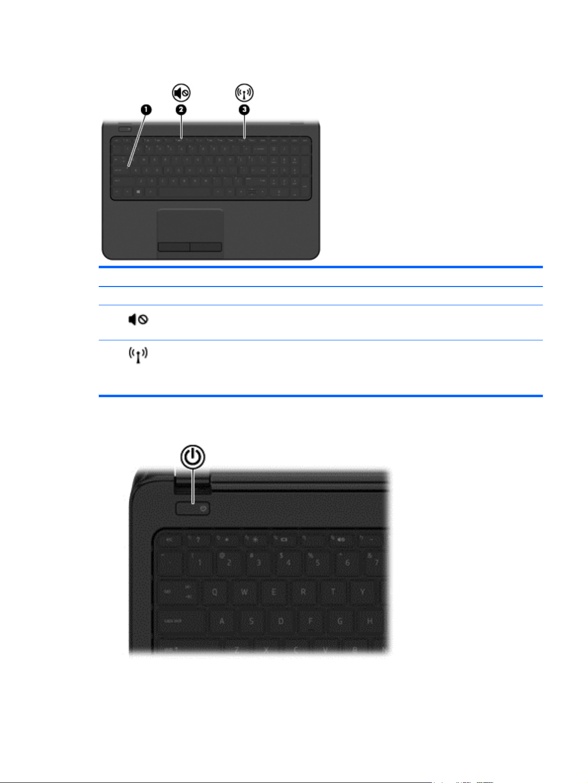
Lights
Component Description
(1) Caps lock light On: Caps lock is on, which switches the keys to all capital letters.
Button
(2)
(3)
Mute light
Wireless light On: An integrated wireless device, such as a wireless local area
●
Amber: Computer sound is off.
●
Off: Computer sound is on.
network (WLAN) device and/or a Bluetooth® device, is on.
NOTE: On some models, the wireless light is amber when all
wireless devices are off.
Top 9

Component Description
Power button
●
When the computer is off, press the button to turn on the
computer.
●
When the computer is on, press the button briefly to
initiate Sleep.
●
When the computer is in the Sleep state, press the button
briefly to exit Sleep.
●
When the computer is in Hibernation, press the button
briefly to exit Hibernation.
CAUTION: Pressing and holding down the power button will
result in the loss of unsaved information.
If the computer has stopped responding and shutdown
procedures are ineffective, press and hold the power button
down for at least 5 seconds to turn off the computer.
To learn more about your power settings, see your power
options. In Windows 8.1, from the Start screen, type power,
select Power and sleep settings, and then select Power and
sleep from the list of applications.
10 Chapter 2 External component identification
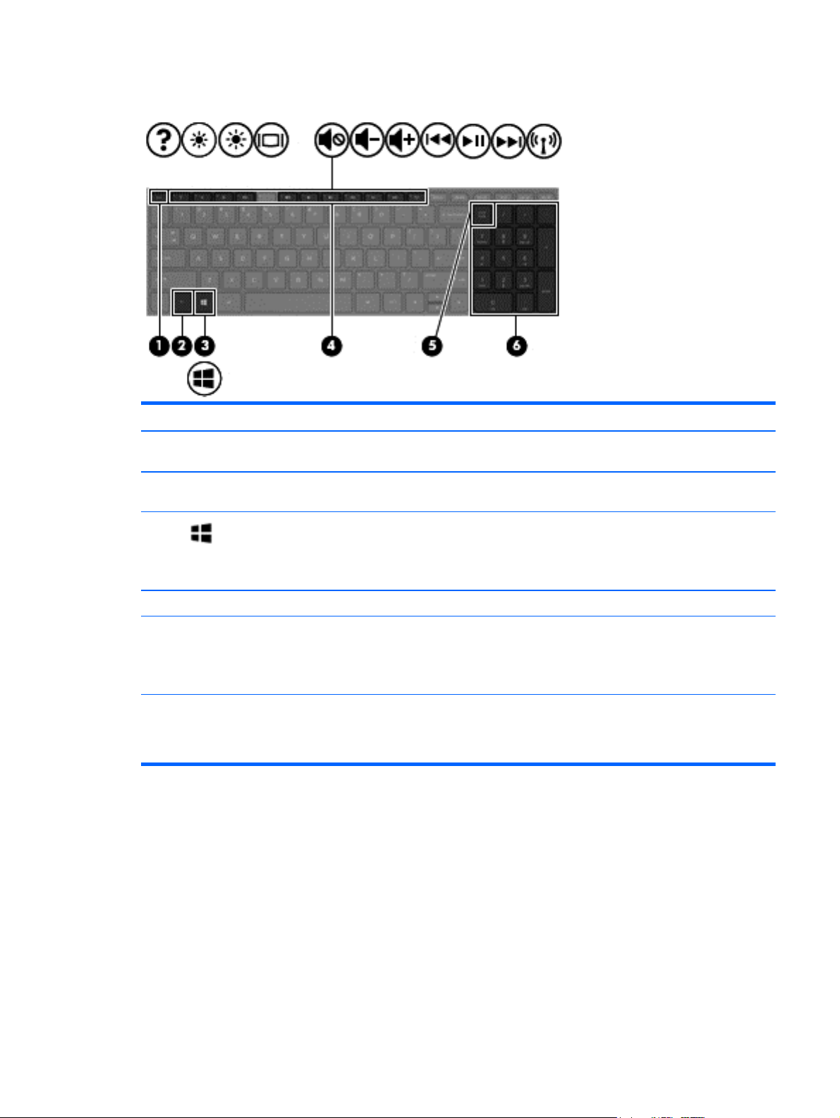
Keys
Component Description
(1) esc key Displays system information when pressed in combination with
the fn key.
(2) fn key Executes frequently used system functions when pressed in
combination with the spacebaror the esc key.
(3)
(4) Action keys Execute frequently used system functions.
(5) num lk key Alternates between the navigational and numeric functions on
(6) Integrated numeric keypad When num lk has been enabled, it can be used like an external
Windows key (Windows 8.1) Returns you to the Start screen from an open
app or the Windows desktop.
NOTE: Pressing the Windows key again will return you to the
previous screen.
the integrated numeric keypad.
NOTE: The keypad function that is active when the computer
is turned off is reinstated when the computer is turned back on.
numeric keypad. To alternate between this numeric function
and the navigational function (indicated by the directional
arrows on the keys), press the num lk key.
Top 11
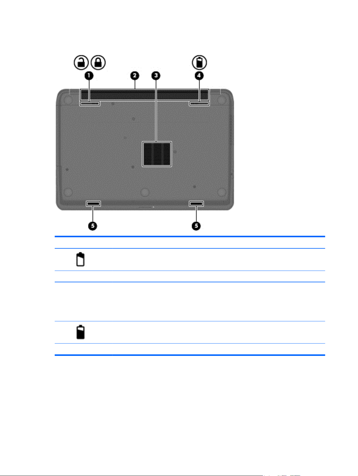
Bottom
Component Description
(1)
(2) Battery bay Holds the battery.
(3) Vent Enable airflow to cool internal components.
(4)
(5) Speaker openings (2) Produce sound.
Battery lock and unlock latch Locks and unlocks the battery in the battery bay.
NOTE: The computer fan starts up automatically to cool
internal components and prevent overheating. It is normal
for the internal fan to cycle on and off during routine
operation.
Battery release latch Releases the battery.
12 Chapter 2 External component identification
Labels
The labels affixed to the computer provide information you may need when you troubleshoot system
problems or travel internationally with the computer.
IMPORTANT: All labels described in this section will be located in one of 2 places depending on your
computer model: Affixed to the bottom of the computer, or located in the battery bay.
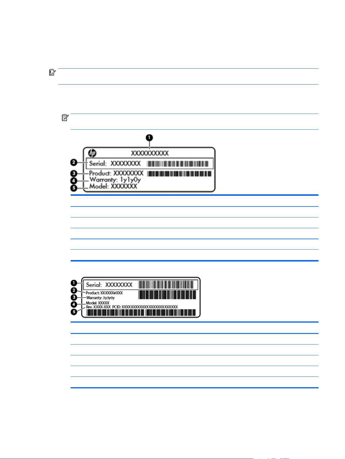
●
Service label—Provides important information to identify your computer. When contacting support,
you will probably be asked for the serial number, and possibly for the product number or the model
number. Locate these numbers before you contact support.
NOTE: Your service labels will resemble one of the examples shown below. Refer to the illustration
that most closely matches the service label on your computer.
Component
(1) Product name
(2) Serial number
(3) Product number
(4) Warranty period
(5) Model number (select models only)
Component
(1) Serial number
(2) Product number
(3) Warranty period
(4) Model number (select models only)
(5) Revision number
●
Regulatory label(s)—Provide(s) regulatory information about the computer.
●
Wireless certification label(s)—Provide(s) information about optional wireless devices and the approval
markings for the countries or regions in which the devices have been approved for use.
Labels 13

14 Chapter 2 External component identification

3 Illustrated parts catalog
Computer major components
NOTE: HP continually improves and changes product parts. For complete and current information on
supported parts for your computer, go to
follow the on-screen instructions.
http://partsurfer.hp.com, select your country or region, and then
Computer major components 15
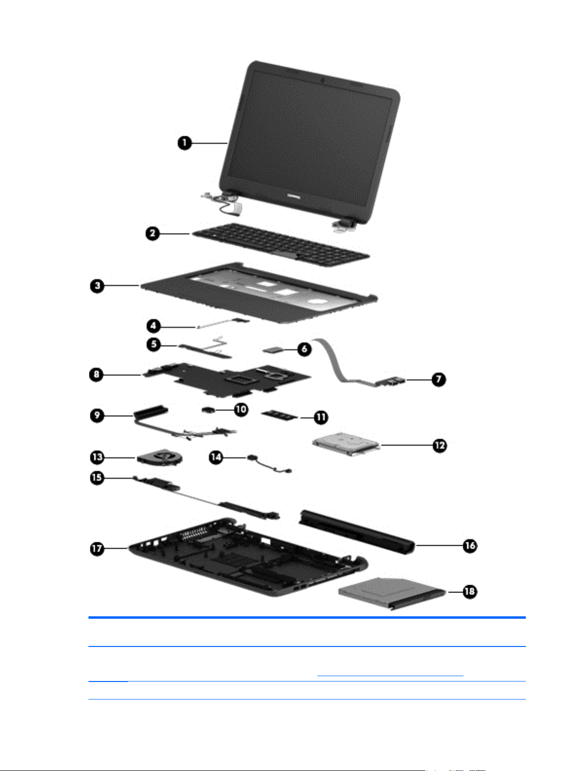
Item Component Spare part
number
(1) Display assembly (39.6-cm [15.6-in] HD, anti-glare, touchscreen)
NOTE: For display assembly spare part information, see
(2) Keyboard
16 Chapter 3 Illustrated parts catalog
Display assembly subcomponents on page 21.

Item Component Spare part
For use in the United States 749658-001
For use in the United Kingdom 749658-031
For use in Germany 749658-041
For use in France 749658-051
For use in Italy 749658-061
For use in Spain 749658-071
For use in Portugal 749658-131
For use in Turkey 749658-141
For use in Greece 749658-151
For use in Latin America 749658-161
For use in Saudi Arabia 749658-171
For use in Hungary 749658-211
For use in Russia 749658-251
For use in Bulgaria 749658-261
For use in Romania 749658-271
number
For use in Thailand 749658-281
For use in Japan 749658-291
For use in Belgium 749658-A41
For use in Taiwan 749658-AB1
For use in South Korea 749658-AD1
For use in the Netherlands 749658-B31
For use in Slovenia 749658-BA1
For use in Israel 749658-BB1
For use in Switzerland 749658-BG1
For use in French Canada 749658-DB1
For use in Denmark, Finland, and Norway 749658-DH1
For use in the Czech Republic and Slovakia 749658-FL1
(3) Top cover (includes touchpad) 754214-001
(4) Power button board (includes cable) 749650-001
(5) Touchpad button board (includes bracket) 749651-001
(6) WLAN module:
Ralink RT3290LE 802.11bgn 1x1 Wi-Fi and Bluetooth 4.0 Combo Adapter 690020-001
Realtek RT8723BE 802.11bgn 1x1 Wi-Fi + BT4.0 Combo Adapter 753077-001
Realtek RTL8188EE 802.11bgn Wi-Fi Adapter 709848-001
Computer major components 17

Item Component Spare part
Atheros AR9485 802.11b/g/n 1x1 WiFi Adapter 675794-001
Atheros AR9565 802.11bgn + Bluetooth 4.0 Wi-Fi Adapter 733476-001
Broadcom BCM43142 802.11 bgn 1x1 Wi-Fi + BT4.0 HMC Combo Adapter 753076-001
(7) USB board (includes cable) 749649-001
(8) System board (includes replacement thermal materials):
All system boards use the following part numbers:
xxxxxx-001: Without the Windows operating system
xxxxxx-501: Windows 8.1 Standard
xxxxxx-601: Windows 8.1 Professional
Touch screen models:
number
Non-touch screen models:
●
Intel Core i3-3217U processor and UMA graphics 763753-xxx
●
Intel Core i3-4005U processor and UMA graphics 774715-xxx
●
Intel Core i3-4010U processor and 1 GB of discrete graphics 763752-xxx
●
Intel Core i3-4030U processor and 1 GB of discrete graphics 780126-xxx
●
Intel Celeron N2815 processor and UMA graphics 761543-xxx
●
Intel Celeron N2830 processor and UMA graphics 774711-xxx
●
Intel Celeron N2840 processor and UMA graphics 787810-xxx
●
Intel Pentium N3520 processor and UMA graphics 761541-xxx
●
Intel N3530 processor and UMA graphics 774712-xxx
●
Intel N3540 processor and UMA graphics 787809-xxx
●
Intel Core i3-3217U processor and UMA graphics 761537-xxx
●
Intel Core i3-3217U processor and UMA graphics 761538-xxx
●
Intel Core i3-3217U processor and 1 GB of discrete graphics 761540-xxx
●
Intel Core i3-4005U processor and UMA graphics 774716-xxx
●
Intel Core i3-4005U processor, UMA graphics memory, and an Integrated 10/100/1000 NIC (Giga
LAN)
785481-xxx
●
Intel Core i3-4005U processor and 1 GB of discrete graphics 774714-xxx
●
Intel Core i3-4005U processor and 2 GB of discrete graphics memory in HP 250 and 256 G3 models 780128-xxx
●
Intel Core i3-4010U processor and 1 GB of discrete graphics 761539-xxx
●
Intel Core i3-4010U processor and UMA graphics 761536-xxx
●
Intel Core i3-4030U processor and UMA graphics memory in HP 250 G3 models 780124-xxx
●
Intel Core i3-4030U processor and UMA graphics memory in HP 250 and 256 G3 models with an
Integrated 10/100/1000 NIC (Giga LAN)
●
Intel Core i3-4030U processor and 1 GB of discrete graphics memory in HP 250 G3 models 780125-xxx
18 Chapter 3 Illustrated parts catalog
786713-xxx

Item Component Spare part
number
(9) Heat sink assembly (includes replacement thermal materials):
For use in models with UMA graphics 753895-001
For use in models with discrete graphics 762728-001
(10) RTC battery 759981-001
(11) Memory module (PC3L, 12800, 1600-MHz):
8-GB 693374-001
4 GB 691740-001
2 GB 691739-001
(12) Hard drive (SATA; does not include bracket):
1-GB, 5400-rpm, 2.5-inch 676521-001
●
Intel Core i3-4030U processor and 2 GB of discrete graphics memory in HP 256 G3 models 780127-xxx
●
Intel Core i5-4210U processor and UMA graphics memory in models 761535-xxx
●
Intel Core i5-4210U processor and UMA graphics memory in HP 250 G3 models with an Integrated
10/100/1000 NIC (Giga LAN)
●
Intel Core i5-4210U processor and 2 GB of discrete graphics memory in HP 250 and 256 G3 models 780120-xxx
●
Intel Core i5 processor and UMA graphics 780118-xxx
NOTE: The hard drive bracket is available using spare part number 749648-001.
780119-xxx
750 GB, 5400 rpm, 2.5 inch 634250-001
500-GB, 7200-rpm, 7-mm 703267-001
500-GB, 5400-rpm, 2.5-inch 669299-001
320-GB, 5400-rpm, 2.5-inch 622643-001
(13) Fan 753894-001
(14) Power connector cable 749647-001
(15) Speakers (includes left and right speakers and cable) 749653-001
(16) Battery:
4-cell, 41-Whr, 2.8-Ah Li-ion battery 740715-001
3-cell, 31-Whr, 2.8-Ah Li-ion battery 746641-001
(17) Base enclosure 754213-001
(18) Optical drive (DVD+/-RW Double-Layer SuperMulti) 750636-001
Miscellaneous parts
Component Spare part number
HP Smart AC adapter:
Miscellaneous parts 19

Component Spare part number
65-W, non-PFC, 4.5 mm (for use in all countries and regions except for the People’s Republic of China
and India)
45-W non-PFC, non-slim HP Smart AC adapter (for use in all countries and regions except for the
People’s Republic of China and India)
Power cord (3-pin, black, 1.00-m):
●
For use in Australia 755530-011
●
For use in Europe, the Middle East, and Africa 755530-021
●
For use in Denmark 755530-081
●
For use in India 755530-D61
●
For use in Israel 755530-BB1
●
For use in Japan 755530-291
●
For use in North America 755530-001
●
For use in the People's Republic of China 755530-AA1
●
For use in South Africa 755530-AR1
●
For use in South Korea 755530-AD1
●
For use in Switzerland 755530-111
●
For use in Taiwan 755530-AB1
710412-001
741727-001
●
For use in Thailand 755530-201
●
For use in the United Kingdom and Singapore 755530-031
Rubber Kit (includes front and rear feet) 749652-001
Screw Kit 749657-001
Case, top load, for use in HP 250/256 G3 models 679921-001
20 Chapter 3 Illustrated parts catalog
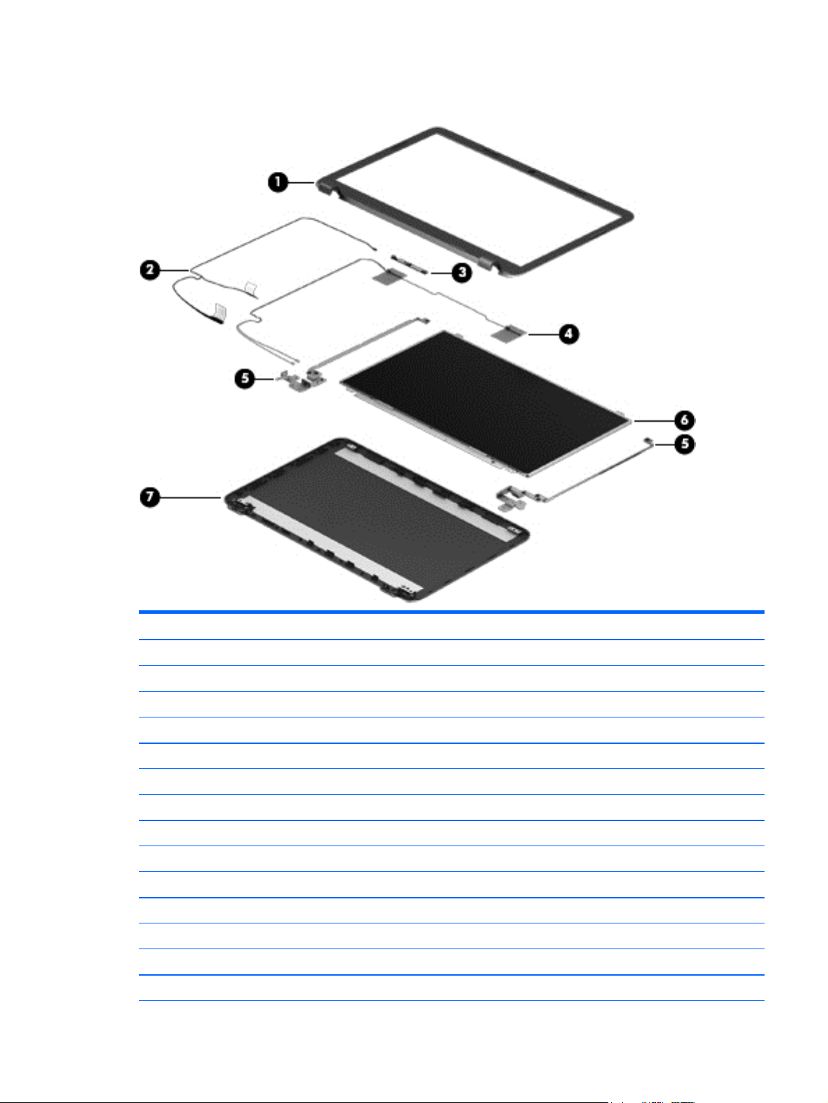
Display assembly subcomponents
Item Component Spare part number
(1) Display bezel (includes Mylar screw covers):
For use in HP 250 G3 models 749644-001
For use in HP 256 G3 models (China only) 783998-001
(2) Display cable (includes display panel cable and webcam/microphone cable) 749646-001
(3) Webcam/microphone module 749654-001
(4) Antennas (includes wireless antenna cables and transceivers)
For use in models without a touch screen 749638-001
For use in models with a touch screen 774163-001
(5) Hinges (left and right) 749655-001
For use in models without a touch screen 749655-001
For use in models with a touch screen 774166-001
(6) Raw display panel (39.6-cm [15.6-in], HD, WLED, BrightView)
Non-touch screen 750635-001
Touch screen 774165-001
Display assembly subcomponents 21
Item Component Spare part number
(7) Display enclosure:
For use in touch screen models 774164-001
For use in non-touch screen models 749641-001
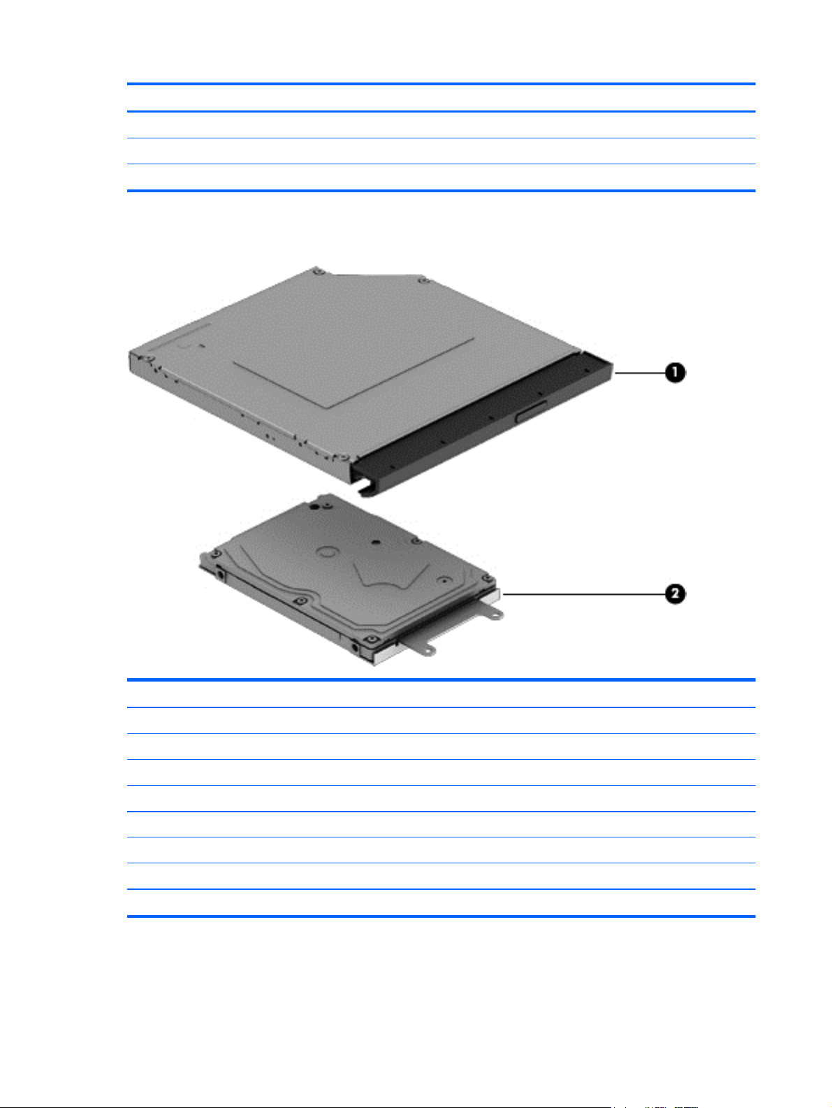
Mass storage devices
Item Component Spare part number
(1) Optical drive (DVD+/-RW Double-Layer SuperMulti) 750636-001
(2) Hard drive, SATA; does not include bracket):
1-GB, 5400-rpm, 2.5-inch 676521-001
750 GB, 5400 rpm, 2.5 inch 634250-001
500-GB, 7200-rpm, 7-mm 703267-001
500-GB, 5400-rpm, 2.5-inch 669299-001
320-GB, 5400-rpm, 2.5-inch 622643-001
Hard drive bracket 749648-001
22 Chapter 3 Illustrated parts catalog

Plastics Kit
Item Component Spare part number
Plastics Kit, includes: 749656-001
(1) Left cover
(2) Right cover
Rubber Kit
Component Spare part number
Rubber Kit, includes: 749652-001
Front feet
Rear feet
Plastics Kit 23

Sequential part number listing
CSR flag designations:
●
A = Mandatory
●
B = Optional
●
C = Service technician recommended
●
N = Non-user replaceable
Spare part
number
622643-001 A 320-GB, 5400-rpm, 2.5-in SATA hard drive (does not include cable or bracket)
634250-001 A 750 GB, 5400 rpm, 2.5 in hard drive (does not include cable or bracket)
669299-001 A 500-GB, 5400-rpm, 2.5-in SATA hard drive (does not include cable or bracket)
675794-001 A Atheros AR9485 802.11b/g/n 1x1 WiFi Adapter
676521-001 A 1-TB, 5400-rpm, 2.5-in SATA hard drive (does not include cable or bracket)
679921-001 A Case, top load
690020-001 A Ralink RT3290LE 802.11bgn 1x1 Wi-Fi and Bluetooth 4.0 Combo Adapter
691739-001 A 2-GB memory module (PC3L, 12800, 1600-MHz)
691740-001 A 4-GB memory module (PC3L, 12800, 1600-MHz)
693374-001 A 8-GB memory module (PC3L, 12800, 1600-MHz)
703267-001 A 500-GB, 7200-rpm, 7-mm hard drive
709848-001 A Realtek RTL8188EE 802.11bgn Wi-Fi Adapter
710412-001 N AC adapter, 65-W, non-PFC, 4.5 mm
733476-001 A Atheros AR9565 802.11bgn + Bluetooth 4.0 Wi-Fi Adapter
740715-001 A 4-cell, 41-Whr, 2.8-Ah Li-ion battery
CSR flag Description
741727-001 A 45-W non-PFC, non-slim HP Smart AC adapter (for use in all countries and regions except for the People’s
Republic of China and India)
746641-001 A 3-cell, 31-Whr, 2.8-Ah Li-ion battery
749638-001 N Antennas for use in models without a touch screen (includes wireless antenna cables and transceivers)
749641-001 N Display enclosure for use in non-touch screen models
749644-001 N Display bezel for use in HP 250 G3 models
749646-001 N Display cable for use in models with out a touch screen (includes display panel cable and webcam/
microphone cable)
749647-001 N Power connector cable
749648-001 N Hard drive bracket
749649-001 N USB board (includes cable)
749650-001 N Power button board (includes cable)
749651-001 N TouchPad button board (includes bracket)
24 Chapter 3 Illustrated parts catalog

Spare part
number
749652-001 N Rubber Kit (includes front and rear feet)
749653-001 N Speakers (includes left and right speakers and cable)
749654-001 N Webcam/microphone module, HD
749655-001 N Hinges for use in models without a touch screen (left and right)
749656-001 N Plastics Kit (includes left and right covers)
749657-001 N Screw Kit
749658-001 B Keyboard for use in the United States
749658-031 B Keyboard for use in the United Kingdom
749658-041 B Keyboard for use in Germany
749658-051 B Keyboard for use in France
749658-061 B Keyboard for use in Italy
749658-071 B Keyboard for use in Spain
749658-131 B Keyboard for use in Portugal
749658-141 B Keyboard for use in Turkey
749658-151 B Keyboard for use in Greece
CSR flag Description
749658-161 B Keyboard for use in Latin America
749658-171 B Keyboard for use in Saudi Arabia
749658-211 B Keyboard for use in Hungary
749658-251 B Keyboard for use in Russia
749658-261 B Keyboard for use in Bulgaria
749658-271 B Keyboard for use in Romania
749658-281 B Keyboard for use in Thailand
749658-291 B Keyboard for use in Japan
749658-A41 B Keyboard for use in Belgium
749658-AB1 B Keyboard for use in Taiwan
749658-AD1 B Keyboard for use in South Korea
749658-B31 B Keyboard for use in the Netherlands
749658-BA1 B Keyboard for use in Slovenia
749658-BB1 B Keyboard for use in Israel
749658-BG1 B Keyboard for use in Switzerland
749658-DB1 B Keyboard for use in French Canada
749658-DH1 B Keyboard for use in Denmark, Finland, and Norway
749658-FL1 B Keyboard for use in the Czech Republic and Slovakia
750635-001 N Raw display panel, non-touch screen
Sequential part number listing 25

Spare part
number
750636-001 A DVD+/-RW Double-Layer SuperMulti Drive
753076-001 A Broadcom BCM43142 802.11 bgn 1x1 Wi-Fi + BT4.0 HMC Combo Adapter
753077-001 A Realtek RT8723BE 802.11bgn 1x1 Wi-Fi + BT4.0 Combo Adapter
753894-001 N Fan
753895-001 N Heat sink for use in models with UMA graphics
754213-001 N Base enclosure
754214-001 N Top cover (includes touchpad)
755530-001 A Power cord for use in Intel models in North America (3-pin, black, 1.00-m)
755530-011 A Power cord for use in Intel models in Australia (3-pin, black, 1.00-m)
755530-021 A Power cord for use in Intel models in Europe, the Middle East, and Africa (3-pin, black, 1.00-m)
755530-031 A Power cord for use in Intel models in the United Kingdom and Singapore (3-pin, black, 1.00-m)
755530-081 A Power cord for use in Intel models in Denmark (3-pin, black, 1.00-m)
755530-111 A Power cord for use in Intel models in Switzerland (3-pin, black, 1.00-m)
755530-201 A Power cord for use in Intel models in Thailand (3-pin, black, 1.00-m)
755530-291 A Power cord for use in Intel models in Japan (3-pin, black, 1.00-m)
CSR flag Description
755530-AA1 A Power cord for use in Intel models in the People's Republic of China (3-pin, black, 1.00-m)
755530-AB1 A Power cord for use in Intel models in Taiwan (3-pin, black, 1.00-m)
755530-AD1 A Power cord for use in Intel models in South Korea (3-pin, black, 1.00-m)
755530-AR1 A Power cord for use in Intel models in South Africa (3-pin, black, 1.00-m)
755530-BB1 A Power cord for use in Intel models in Israel (3-pin, black, 1.00-m)
755530-D61 A Power cord for use in Intel models in India (3-pin, black, 1.00-m)
759981-001 N RTC battery
761535-001 N System board with Intel Core i5-4210U processor and UMA graphics memory for use in models without
Windows 8.1
761535-501 N System board with Intel Core i5-4210U processor and UMA graphics memory for use in models with
Windows 8.1 Standard
761535-601 N System board with Intel Core i5-4210U processor and UMA graphics memory for use in models with
Windows 8.1 Professional
761536-001 N System board with Intel Core i3-4010U processor and UMA graphics memory for use in models without
Windows 8.1
761536-501 N System board with Intel Core i3-4010U processor and UMA graphics memory for use in models with
Windows 8.1 Standard
761536-601 N System board with Intel Core i3-4010U processor and UMA graphics memory for use in models with
Windows 8.1 Professional
761537-001 N System board with Intel Core i3-3217U processor and UMA graphics memory for use in models without
Windows 8.1
26 Chapter 3 Illustrated parts catalog

Spare part
number
761537-501 N System board with Intel Core i3-3217U processor and UMA graphics memory for use in models with
761537-601 N System board with Intel Core i3-3217U processor and UMA graphics memory for use in models with
761538-001 N System board with Intel Core i3-3217U processor and UMA graphics memory for use in models without
761538-501 N System board with Intel Core i3-3217U processor and UMA graphics memory for use in models with
761538-601 N System board with Intel Core i3-3217U processor and UMA graphics memory for use in models with
761539-001 N System board with Intel Core i3-4010U processor and 1 GB of discrete graphics memory for use in models
761539-501 N System board with Intel Core i3-4010U processor and 1 GB of discrete graphics memory for use in models
761539-601 N System board with Intel Core i3-4010U processor and 1 GB of discrete graphics memory for use in models
761540-001 N System board with Intel Core i3-3217U processor and 1 GB of discrete graphics memory for use in models
761540-501 N System board with Intel Core i3-3217U processor and 1 GB of discrete graphics memory for use in models
CSR flag Description
Windows 8.1 Standard
Windows 8.1 Professional
Windows 8.1 and with WWAN
Windows 8.1 Standard and with WWAN
Windows 8.1 Professional and with WWAN
without Windows 8.1
with Windows 8.1 Standard
with Windows 8.1 Professional
without Windows 8.1
with Windows 8.1 Standard
761540-601 N System board with Intel Core i3-3217U processor and 1 GB of discrete graphics memory for use in models
with Windows 8.1 Professional
761541-001 N System board with Intel Pentium N3520 processor and UMA graphics memory for use in models without
Windows 8.1
761541-501 N System board with Intel Pentium N3520 processor and UMA graphics memory for use in models with
Windows 8.1 Standard
761541-601 N System board with Intel Pentium N3520 processor and UMA graphics memory for use in models with
Windows 8.1 Professional
761543-001 N System board with Intel Celeron N2815 processor and UMA graphics memory for use in models without
Windows 8.1
761543-501 N System board with Intel Celeron N2815 processor and UMA graphics memory for use in models with
Windows 8.1 Standard
761543-601 N System board with Intel Celeron N2815 processor and UMA graphics memory for use in models with
Windows 8.1 Professional
762728-001 N Heat sink for use in models with discrete graphics
763752-001 N System board with Intel Core i3-4010U processor and 1 GB of discrete graphics memory for use in touch
screen models without Windows 8.1
763752-501 N System board with Intel Core i3-4010U processor and 1 GB of discrete graphics memory for use in touch
screen models with Windows 8.1 Standard
763752-601 N System board with Intel Core i3-4010U processor and 1 GB of discrete graphics memory for use in touch
screen models with Windows 8.1 Professional
763753-001 N System board with Intel Core i3-3217U processor and UMA graphics memory for use in touch screen
models without Windows 8.1
Sequential part number listing 27

Spare part
number
763753-501 N System board with Intel Core i3-3217U processor and UMA graphics memory for use in touch screen
763753-601 N System board with Intel Core i3-3217U processor and UMA graphics memory for use in touch screen
774163-001 N Antennas for use in models with a touch screen
774164-001 N Display enclosure for use in models with a touch screen
774165-001 N Raw display panel, touch screen, includes bezel
774166-001 N Hinges for use in models with a touch screen (left and right)
774711-001 N System board with Intel Celeron N2830 processor and UMA graphics memory for use in models without
774711-501 N System board with Intel Celeron N2830 processor and UMA graphics memory for use in models with
774711-601 N System board with Intel Celeron N2830 processor and UMA graphics memory for use in models with
774712-001 N System board with Intel Pentium N3530 processor and UMA graphics memory for use in models without
774712-501 N System board with Intel Pentium N3530 processor and UMA graphics memory for use in models with
CSR flag Description
models with Windows 8.1 Standard
models with Windows 8.1 Professional
Windows 8.1
Windows 8.1 Standard
Windows 8.1 Professional
Windows 8.1
Windows 8.1 Standard
774712-601 N System board with Intel Pentium N3530 processor and UMA graphics memory for use in models with
Windows 8.1 Professional
774714-001 N System board with Intel Core i3-4005U processor and 1 GB of discrete graphics memory for use in models
without Windows 8.1
774714-501 N System board with Intel Core i3-4005U processor and 1 GB of discrete graphics memory for use in models
with Windows 8.1 Standard
774714-601 N System board with Intel Core i3-4005U processor and 1 GB of discrete graphics memory for use in models
with Windows 8.1 Professional
774715-001 N System board with Intel Core i3-4005U processor and UMA graphics memory for use in touch screen
models without Windows 8.1
774715-501 N System board with Intel Core i3-4005U processor and UMA graphics memory for use in touch screen
models with Windows 8.1 Standard
774715-601 N System board with Intel Core i3-4005U processor and UMA graphics memory for use in touch screen
models with Windows 8.1 Professional
774716-001 N System board with Intel Core i3-4005U processor and UMA graphics memory for use in models without
Windows 8.1
774716-501 N System board with Intel Core i3-4005U processor and UMA graphics memory for use in models with
Windows 8.1 Standard
774716-601 N System board with Intel Core i3-4005U processor and UMA graphics memory for use in models with
Windows 8.1 Professional
780118-001 N System board with Intel Core i5 processor and UMA graphics memory for use in HP 250 G3 models without
Windows 8.1
780118-501 N System board with Intel Core i5 processor and UMA graphics memory for use in HP 250 G3 models with
Windows 8.1 Standard
28 Chapter 3 Illustrated parts catalog

Spare part
number
780118-601 N System board with Intel Core i5 processor and UMA graphics memory for use in HP 250 G3 models with
780119-001 N System board with Intel Core i5-4210U processor and UMA graphics memory for use in HP 250 G3 models
780119-501 N System board with Intel Core i5-4210U processor and UMA graphics memory for use in HP 250 G3 models
780119-601 N System board with Intel Core i5-4210U processor and UMA graphics memory for use in HP 250 G3 models
780120-001 N System board with Intel Core i5-4210U processor and 2 GB of discrete graphics memory for use in HP 250
780120-501 N System board with Intel Core i5-4210U processor and 2 GB of discrete graphics memory for use in HP 250
780120-601 N System board with Intel Core i5-4210U processor and 2 GB of discrete graphics memory for use in HP 250
780124-001 N System board with Intel Core i3-4030U processor and UMA graphics memory for use in HP 250 G3 models
780124-501 N System board with Intel Core i3-4030U processor and UMA graphics memory for use in HP 250 G3 models
780124-601 N System board with Intel Core i3-4030U processor and UMA graphics memory for use in HP 250 G3 models
CSR flag Description
Windows 8.1 Professional
without Windows 8.1 and with an Integrated 10/100/1000 NIC (Giga LAN)
with Windows 8.1 Standard and with an Integrated 10/100/1000 NIC (Giga LAN)
with Windows 8.1 Professional and with an Integrated 10/100/1000 NIC (Giga LAN)
and 256 G3 models without Windows 8.1
and 256 G3 models with Windows 8.1 Standard
and 256 G3 models with Windows 8.1 Professional
without Windows 8.1
with Windows 8.1 Standard
with Windows 8.1 Professional
780125-001 N System board with Intel Core i3-4030U processor and 1 GB of discrete graphics memory for use in HP 250
G3 models non-touch screen models without Windows 8.1
780125-501 N System board with Intel Core i3-4030U processor and 1 GB of discrete graphics memory for use in HP 250
G3 models non-touch screen models with Windows 8.1 Standard
780125-601 N System board with Intel Core i3-4030U processor and 1 GB of discrete graphics memory for use in HP 250
G3 models non-touch screen models with Windows 8.1 Professional
780126-001 N System board with Intel Core i3-4030U processor and 1 GB of discrete graphics memory for use in HP 250
G3 models touch screen models without Windows 8.1
780126-501 N System board with Intel Core i3-4030U processor and 1 GB of discrete graphics memory for use in HP 250
G3 models touch screen models with Windows 8.1 Standard
780126-601 N System board with Intel Core i3-4030U processor and 1 GB of discrete graphics memory for use in HP 250
G3 models touch screen models with Windows 8.1 Professional
780127-001 N System board with Intel Core i3-4030U processor and 2 GB of discrete graphics memory for use in HP 256
G3 models touch screen models without Windows 8.1
780127-501 N System board with Intel Core i3-4030U processor and 2 GB of discrete graphics memory for use in HP 256
G3 models touch screen models with Windows 8.1 Standard
780127-601 N System board with Intel Core i3-4030U processor and 2 GB of discrete graphics memory for use in HP 256
G3 models touch screen models with Windows 8.1 Professional
780128-001 N System board with Intel Core i3-4005U processor and 2 GB of discrete graphics memory for use in HP 256
G3 models without Windows 8.1
780128-501 N System board with Intel Core i3-4005U processor and 2 GB of discrete graphics memory for use in HP 256
G3 models with Windows 8.1 Standard
780128-601 N System board with Intel Core i3-4005U processor and 2 GB of discrete graphics memory for use in HP 256
G3 models with Windows 8.1 Professional
Sequential part number listing 29

Spare part
number
783998-001 N Display bezel for use in HP 256 G3 models (China only)
785481-001 N System board with Intel Core i3-4005U processor and UMA graphics memory for use in HP 250 and 256 G3
785481-501 N System board with Intel Core i3-4005U processor and UMA graphics memory for use in HP 250 and 256 G3
785481-601 N System board with Intel Core i3-4005U processor and UMA graphics memory for use in HP 250 and 256 G3
786713-001 N System board with Intel Core i3-4030U processor and UMA graphics memory for use in HP 250 and 256 G3
786713-501 N System board with Intel Core i3-4030U processor and UMA graphics memory for use in HP 250 and 256 G3
786713-601 N System board with Intel Core i3-4030U processor and UMA graphics memory for use in HP 250 and 256 G3
787809-001 N System board with Intel Pentium N3540 processor and UMA graphics memory for use in HP 250 G3 models
787809-501 N System board with Intel Pentium N3540 processor and UMA graphics memory for use in HP 250 G3 models
787809-601 N System board with Intel Pentium N3540 processor and UMA graphics memory for use in HP 250 G3 models
CSR flag Description
models without Windows 8.1 and with an Integrated 10/100/1000 NIC (Giga LAN)
models with Windows 8.1 Standard and with an Integrated 10/100/1000 NIC (Giga LAN)
models with Windows 8.1 Professional and with an Integrated 10/100/1000 NIC (Giga LAN)
models without Windows 8.1 and with an Integrated 10/100/1000 NIC (Giga LAN)
models with Windows 8.1 Standard and with an Integrated 10/100/1000 NIC (Giga LAN)
models with Windows 8.1 Professional and with an Integrated 10/100/1000 NIC (Giga LAN)
without Windows 8.1
with Windows 8.1 Standard
with Windows 8.1 Professional
787810-001 N System board with Intel Celeron N2840 processor and UMA graphics memory for use in HP 250 G3 models
without Windows 8.1
787810-501 N System board with Intel Celeron N2840 processor and UMA graphics memory for use in HP 250 G3 models
with Windows 8.1 Standard
787810-601 N System board with Intel Celeron N2840 processor and UMA graphics memory for use in HP 250 G3 models
with Windows 8.1 Professional
30 Chapter 3 Illustrated parts catalog

4 Removal and replacement procedures
preliminary requirements
Tools required
You will need the following tools to complete the removal and replacement procedures:
●
Flat-bladed screwdriver
●
Magnetic screwdriver
●
Phillips P0 and P1 screwdrivers
Service considerations
The following sections include some of the considerations that you must keep in mind during disassembly
and assembly procedures.
NOTE: As you remove each subassembly from the computer, place the subassembly (and all accompanying
screws) away from the work area to prevent damage.
Plastic parts
CAUTION: Using excessive force during disassembly and reassembly can damage plastic parts. Use care
when handling the plastic parts. Apply pressure only at the points designated in the
maintenance instructions.
Cables and connectors
CAUTION: When servicing the computer, be sure that cables are placed in their proper locations during the
reassembly process. Improper cable placement can damage the computer.
Cables must be handled with extreme care to avoid damage. Apply only the tension required to unseat or
seat the cables during removal and insertion. Handle cables by the connector whenever possible. In all cases,
avoid bending, twisting, or tearing cables. Be sure that cables are routed in such a way that they cannot be
caught or snagged by parts being removed or replaced. Handle flex cables with extreme care; these cables
tear easily.
Tools required 31

Drive handling
CAUTION: Drives are fragile components that must be handled with care. To prevent damage to the
computer, damage to a drive, or loss of information, observe these precautions:
Before removing or inserting a hard drive, shut down the computer. If you are unsure whether the computer
is off or in Hibernation, turn the computer on, and then shut it down through the operating system.
Before handling a drive, be sure that you are discharged of static electricity. While handling a drive, avoid
touching the connector.
Before removing a diskette drive or optical drive, be sure that a diskette or disc is not in the drive and be sure
that the optical drive tray is closed.
Handle drives on surfaces covered with at least one inch of shock-proof foam.
Avoid dropping drives from any height onto any surface.
After removing a hard drive, an optical drive, or a diskette drive, place it in a static-proof bag.
Avoid exposing an internal hard drive to products that have magnetic fields, such as monitors or speakers.
Avoid exposing a drive to temperature extremes or liquids.
If a drive must be mailed, place the drive in a bubble pack mailer or other suitable form of protective
packaging and label the package “FRAGILE.”
Grounding guidelines
Electrostatic discharge damage
Electronic components are sensitive to electrostatic discharge (ESD). Circuitry design and structure
determine the degree of sensitivity. Networks built into many integrated circuits provide some protection,
but in many cases, ESD contains enough power to alter device parameters or melt silicon junctions.
A discharge of static electricity from a finger or other conductor can destroy static-sensitive devices or
microcircuitry. Even if the spark is neither felt nor heard, damage may have occurred.
An electronic device exposed to ESD may not be affected at all and can work perfectly throughout a normal
cycle. Or the device may function normally for a while, then degrade in the internal layers, reducing its life
expectancy.
CAUTION: To prevent damage to the computer when you are removing or installing internal components,
observe these precautions:
Keep components in their electrostatic-safe containers until you are ready to install them.
Before touching an electronic component, discharge static electricity by using the guidelines described in this
section.
Avoid touching pins, leads, and circuitry. Handle electronic components as little as possible.
If you remove a component, place it in an electrostatic-safe container.
The following table shows how humidity affects the electrostatic voltage levels generated by
different activities.
CAUTION: A product can be degraded by as little as 700 V.
32 Chapter 4 Removal and replacement procedures preliminary requirements

Relative humidity
Event 10% 40% 55%
Walking across carpet 35,000 V 15,000 V 7,500 V
Walking across vinyl floor 12,000 V 5,000 V 3,000 V
Motions of bench worker 6,000 V 800 V 400 V
Removing DIPS from plastic tube 2,000 V 700 V 400 V
Removing DIPS from vinyl tray 11,500 V 4,000 V 2,000 V
Removing DIPS from Styrofoam 14,500 V 5,000 V 3,500 V
Removing bubble pack from PCB 26,500 V 20,000 V 7,000 V
Packing PCBs in foam-lined box 21,000 V 11,000 V 5,000 V
Packaging and transporting guidelines
Follow these grounding guidelines when packaging and transporting equipment:
●
To avoid hand contact, transport products in static-safe tubes, bags, or boxes.
●
Protect ESD-sensitive parts and assemblies with conductive or approved containers or packaging.
Typical electrostatic voltage levels
●
Keep ESD-sensitive parts in their containers until the parts arrive at static-free workstations.
●
Place items on a grounded surface before removing items from their containers.
●
Always be properly grounded when touching a component or assembly.
●
Store reusable ESD-sensitive parts from assemblies in protective packaging or non-conductive foam.
●
Use transporters and conveyors made of antistatic belts and roller bushings. Be sure that mechanized
equipment used for moving materials is wired to ground and that proper materials are selected to avoid
static charging. When grounding is not possible, use an ionizer to dissipate electric charges.
Workstation guidelines
Follow these grounding workstation guidelines:
●
Cover the workstation with approved static-shielding material.
●
Use a wrist strap connected to a properly grounded work surface and use properly grounded tools and
equipment.
●
Use conductive field service tools, such as cutters, screwdrivers, and vacuums.
●
When fixtures must directly contact dissipative surfaces, use fixtures made only of staticsafe materials.
●
Keep the work area free of nonconductive materials, such as ordinary plastic assembly aids
and Styrofoam.
●
Handle ESD-sensitive components, parts, and assemblies by the case or PCM laminate. Handle these
items only at static-free workstations.
Grounding guidelines 33

●
Avoid contact with pins, leads, or circuitry.
●
Turn off power and input signals before inserting or removing connectors or test equipment.
Equipment guidelines
Grounding equipment must include either a wrist strap or a foot strap at a grounded workstation.
●
When seated, wear a wrist strap connected to a grounded system. Wrist straps are flexible straps with a
minimum of one megohm ±10% resistance in the ground cords. To provide proper ground, wear a strap
snugly against the skin at all times. On grounded mats with banana-plug connectors, use alligator clips
to connect a wrist strap.
●
When standing, use foot straps and a grounded floor mat. Foot straps (heel, toe, or boot straps) can be
used at standing workstations and are compatible with most types of shoes or boots. On conductive
floors or dissipative floor mats, use foot straps on both feet with a minimum of one megohm resistance
between the operator and ground. To be effective, the conductive must be worn in contact with the
skin.
The following grounding equipment is recommended to prevent electrostatic damage:
●
Antistatic tape
●
Antistatic smocks, aprons, and sleeve protectors
●
Conductive bins and other assembly or soldering aids
●
Nonconductive foam
●
Conductive tabletop workstations with ground cords of one megohm resistance
●
Static-dissipative tables or floor mats with hard ties to the ground
●
Field service kits
●
Static awareness labels
●
Material-handling packages
●
Nonconductive plastic bags, tubes, or boxes
●
Metal tote boxes
●
Electrostatic voltage levels and protective materials
The following table lists the shielding protection provided by antistatic bags and floor mats.
Material Use Voltage protection level
Antistatic plastics Bags 1,500 V
Carbon-loaded plastic Floor mats 7,500 V
Metallized laminate Floor mats 5,000 V
34 Chapter 4 Removal and replacement procedures preliminary requirements

5 Removal and replacement procedures for
Customer Self-Repair parts
CAUTION: The Customer Self-Repair program is not available in all locations. Installing a part not
supported by the Customer Self-Repair program may void your warranty. Check your warranty to determine
if Customer Self-Repair is supported in your location.
NOTE: HP continually improves and changes product parts. For complete and current information on
supported parts for your computer, go to
follow the on-screen instructions.
Component replacement procedures
NOTE: Please read and follow the procedures described here to access and replace Customer Self-Repair
parts successfully.
NOTE: Details about your computer, including model, serial number, product key, and length of warranty,
are on the service tag at the bottom of your computer. See
This chapter provides removal and replacement procedures for Customer Self-Repair parts.
http://partsurfer.hp.com, select your country or region, and then
Labels on page 13 for details.
Battery
There are as many as 5 screws that must be removed, replaced, or loosened when servicing Customer SelfRepair parts. Make special note of each screw size and location during removal and replacement.
Description Spare part number
4-cell, 41-Whr, 2.8-Ah Li-ion battery 740715-001
3-cell, 31-Whr, 2.8-Ah Li-ion battery 746641-001
Before disassembling the computer, follow these steps:
1. Shut down the computer. If you are unsure whether the computer is off or in Hibernation, turn the
computer on, and then shut it down through the operating system.
2. Disconnect all external devices connected to the computer.
3. Disconnect the power from the computer by first unplugging the power cord from the AC outlet and
then unplugging the AC adapter from the computer.
To remove the battery:
1. Position the computer upside down on a flat surface.
2. Slide the battery lock latch (1), and then slide the battery release latch (2) to release the battery.
Component replacement procedures 35

3. Remove the battery from the computer (3).
36 Chapter 5 Removal and replacement procedures for Customer Self-Repair parts

Optical drive
Description Spare part number
DVD+/-RW Double-Layer SuperMulti Drive 750636-001
Before removing the optical drive, follow these steps:
1. Shut down the computer. If you are unsure whether the computer is off or in Hibernation, turn the
computer on, and then shut it down through the operating system.
2. Disconnect all external devices connected to the computer.
3. Disconnect the power from the computer by first unplugging the power cord from the AC outlet and
then unplugging the AC adapter from the computer.
4. Remove the battery (see
Battery on page 35).
To remove the optical drive:
1. Remove the Phillips PM2.5×5.0 screw (1) that secures the optical drive to the computer.
2. Remove the optical drive (2) by sliding it out of the optical drive bay.
3. If it is necessary to replace the optical drive bracket on the rear of the optical drive, position the optical
drive with the rear panel toward you.
4. Remove the two Phillips PM2.0×3.0 screws (1) that secure the bracket to the optical drive.
Component replacement procedures 37

5. Remove the optical drive bracket (2).
Reverse this procedure to reassemble and install the optical drive.
38 Chapter 5 Removal and replacement procedures for Customer Self-Repair parts

Keyboard
Description Spare part number
Keyboard for use in the United States 749658-001
Keyboard for use in the United Kingdom 749658-031
Keyboard for use in Germany 749658-041
Keyboard for use in France 749658-051
Keyboard for use in Italy 749658-061
Keyboard for use in Spain 749658-071
Keyboard for use in Portugal 749658-131
Keyboard for use in Turkey 749658-141
Keyboard for use in Greece 749658-151
Keyboard for use in Latin America 749658-161
Keyboard for use in Saudi Arabia 749658-171
Keyboard for use in Hungary 749658-211
Keyboard for use in Russia 749658-251
Keyboard for use in Bulgaria 749658-261
Keyboard for use in Romania 749658-271
Keyboard for use in Thailand 749658-281
Keyboard for use in Japan 749658-291
Keyboard for use in Belgium 749658-A41
Keyboard for use in Taiwan 749658-AB1
Keyboard for use in South Korea 749658-AD1
Keyboard for use in the Netherlands 749658-B31
Keyboard for use in Slovenia 749658-BA1
Keyboard for use in Israel 749658-BB1
Keyboard for use in Switzerland 749658-BG1
Keyboard for use in French Canada 749658-DB1
Keyboard for use in Denmark, Finland, and Norway 749658-DH1
Keyboard for use in the Czech Republic and Slovakia 749658-FL1
Before removing the keyboard, follow these steps:
1. Shut down the computer. If you are unsure whether the computer is off or in Hibernation, turn the
computer on, and then shut it down through the operating system.
2. Disconnect all external devices connected to the computer.
Component replacement procedures 39

3. Disconnect the power from the computer by first unplugging the power cord from the AC outlet and
then unplugging the AC adapter from the computer.
4. Remove the battery (see
Battery on page 35).
To remove the keyboard:
1. Position the computer upside down with the front toward you.
2. Remove the two Phillips PM2.5×5.0 screws that secure the keyboard to the computer.
3. Position the computer upright with the front toward you.
4. Lift to rotate up the top of the keyboard (1), and then lift the keyboard (2) to disengage it from the
computer.
40 Chapter 5 Removal and replacement procedures for Customer Self-Repair parts
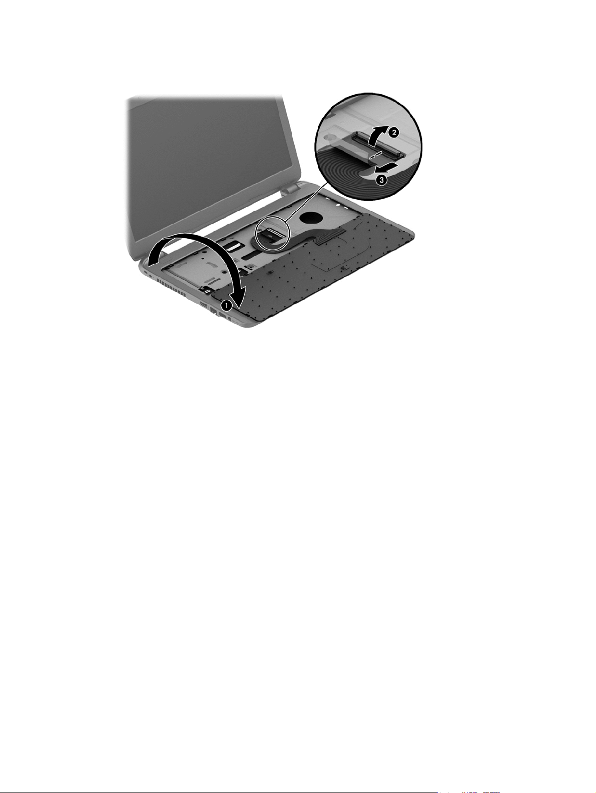
5. Rotate the keyboard over onto the palm rest (1), and the lift the ZIF connector (2) and disconnect the
keyboard cable from the system board (3).
Reverse this procedure to install the keyboard.
Component replacement procedures 41

42 Chapter 5 Removal and replacement procedures for Customer Self-Repair parts

6 Removal and replacement procedures for
Authorized Service Provider parts
CAUTION: Components described in this chapter should only be accessed by an authorized service provider.
Accessing these parts can damage the computer or void the warranty.
NOTE: HP continually improves and changes product parts. For complete and current information on
supported parts for your computer, go to
follow the on-screen instructions.
Component replacement procedures
NOTE: Details about your computer, including model, serial number, product key, and length of warranty,
are on the service tag at the bottom of your computer. See
This chapter provides removal and replacement procedures for Authorized Service Provider only parts.
There are as many as 56 screws that must be removed, replaced, or loosened when servicing Authorized
Service Provider only parts. Make special note of each screw size and location during removal and
replacement.
http://partsurfer.hp.com, select your country or region, and then
Labels on page 13 for details.
Display subcomponents (bezel, webcam, panel)
This section describes removing display subcomponents that do not require that you remove the entire
display assembly from the computer. You can remove the display bezel, webcam/microphone module, and
display panel while the display assembly is still attached to the computer.
To remove the remaining display subcomponents, you must remove the entire display assembly from the
computer. See
its entirety.
Description Spare part number
Raw display panel
Non-touch screen 750635-001
For Touch screen 774165-001
Display bezel
For use in HP 250 G3 models 749644-001
For use in HP 256 G3 models (China only) 783998-001
Webcam/microphone module 749654-001
Before removing display subcomponents while the display assembly is still attached to the computer, follow
these steps:
Display assembly on page 72 for more information about removing the display assembly in
Component replacement procedures 43

1. Shut down the computer. If you are unsure whether the computer is off or in Hibernation, turn the
computer on, and then shut it down through the operating system.
2. Disconnect all external devices connected to the computer.
3. Disconnect the power from the computer by first unplugging the power cord from the AC outlet and
then unplugging the AC adapter from the computer.
4. Remove the battery (see
Battery on page 35).
To remove the display bezel, webcam/microphone module, and raw display panel:
1. Position the computer upright with the front toward you, and then open it.
2. Flex the inside of the top edge (1), the left and right sides (2), and the bottom edge (3) of the display
bezel until the bezel disengages from the display enclosure.
3. Remove the display bezel (4).
4. To remove the webcam/microphone module:
a. Position the display assembly with the top edge toward you.
b. Lift to disengage the adhesive that secures the webcam/microphone module to the display, and
then remove the module enough to access the cable connection on the module (1).
44 Chapter 6 Removal and replacement procedures for Authorized Service Provider parts

c. Disconnect the cable (2) from the module.
5. To remove the display panel:
a. Remove the four Phillips PM2.5×3.5 screws that secure the display panel to the enclosure.
b. Rotate the display panel onto the keyboard to gain access to the display cable connection on the
back of the panel (1).
Component replacement procedures 45

c. On the back of the display panel, release the adhesive strip (2) that secures the display panel cable
to the display panel, and then disconnect the cable (3).
Reverse this procedure to reassemble and install the display bezel, webcam/microphone module, and display
panel.
46 Chapter 6 Removal and replacement procedures for Authorized Service Provider parts

Top cover
NOTE: The top cover spare part kit includes the TouchPad.
Description Spare part number
Top cover (includes touchpad) 754214-001
Before removing the top cover, follow these steps:
1. Shut down the computer. If you are unsure whether the computer is off or in Hibernation, turn the
2. Disconnect all external devices connected to the computer.
3. Disconnect the power from the computer by first unplugging the power cord from the AC outlet and
computer on, and then shut it down through the operating system.
then unplugging the AC adapter from the computer.
4. Remove the battery (see
5. Remove the keyboard (see
Battery on page 35).
Keyboard on page 39).
To remove the top cover:
1. Position the computer upside down with the front toward you.
2. Remove the rear covers by prying off the two rubber feet (1), removing the two Phillips PM2.5×8.0
screws (2) that secure the rear covers to the computer, and then lifting the rear covers off the computer
(3).
3. Remove the two Phillips broadhead PM2.5×2.0 screws from the optical drive bay (4).
Component replacement procedures 47

4. Remove the seven Phillips PM2.5×5.0 screws that secure the top cover to the computer.
5. Position the computer upright with the front toward you.
6. Disconnect the power button board cable (1) and the touchpad button board cable (2).
7. Remove the four Phillips PM2.5×5.0 screws (3) that secure the top cover to the computer.
8. Lift the rear edge of the top cover (1) until it disengage from the base enclosure.
48 Chapter 6 Removal and replacement procedures for Authorized Service Provider parts

9. Remove the top cover (2).
Reverse this procedure to install the top cover.
Component replacement procedures 49

Power button board
Description Spare part number
Power button board (includes cable) 749650-001
Before removing the power button board, follow these steps:
1. Shut down the computer. If you are unsure whether the computer is off or in Hibernation, turn the
computer on, and then shut it down through the operating system.
2. Disconnect all external devices connected to the computer.
3. Disconnect the power from the computer by first unplugging the power cord from the AC outlet and
then unplugging the AC adapter from the computer.
4. Remove the battery (see
5. Remove the keyboard (see
6. Remove the top cover (see
Battery on page 35).
Keyboard on page 39).
Top cover on page 47).
To remove the power button board:
1. Position the top cover upside down.
2. Remove the Phillips PM2.0×3.0 screw (1) that secures the power button board to the top cover.
3. Lift the board and cable up and remove from the top cover (2) while pulling cable through the hole in
top cover (3).
Reverse this procedure to install the power button board and cable.
50 Chapter 6 Removal and replacement procedures for Authorized Service Provider parts

TouchPad button board
Description Spare part number
TouchPad button board (includes bracket) 749651-001
Before removing the TouchPad button board, follow these steps:
1. Shut down the computer. If you are unsure whether the computer is off or in Hibernation, turn the
computer on, and then shut it down through the operating system.
2. Disconnect all external devices connected to the computer.
3. Disconnect the power from the computer by first unplugging the power cord from the AC outlet and
then unplugging the AC adapter from the computer.
4. Remove the battery (see
5. Remove the keyboard (see
6. Remove the top cover (see
Battery on page 35).
Keyboard on page 39).
Top cover on page 47).
To remove the TouchPad button board:
1. Position the top cover upside down with the front toward you.
2. Disconnect the touchpad board cable from the touchpad (1).
3. Remove the two Phillips PM2.0×3.5 screws (2) that secure the TouchPad button board to the top cover.
Component replacement procedures 51

4. Remove the TouchPad button board and cable.
Reverse this procedure to install the power button board and cable.
52 Chapter 6 Removal and replacement procedures for Authorized Service Provider parts

Hard drive
NOTE: The hard drive spare part kit does not include the hard drive bracket.
Description Spare part number
1-GB, 5400-rpm, 2.5-inch 676521-001
750 GB, 5400 rpm, 2.5 inch 634250-001
500-GB, 7200-rpm, 7-mm 703267-001
500-GB, 5400-rpm, 2.5 inch 669299-001
320-GB, 5400-rpm, 2.5-inch 622643-001
Hard drive bracket 749648-001
Before removing the hard drive, follow these steps:
1. Shut down the computer. If you are unsure whether the computer is off or in Hibernation, turn the
2. Disconnect all external devices connected to the computer.
3. Disconnect the power from the computer by first unplugging the power cord from the AC outlet and
computer on, and then shut it down through the operating system.
then unplugging the AC adapter from the computer.
4. Remove the battery (see
5. Remove the keyboard (see
6. Remove the top cover (see
Battery on page 35).
Keyboard on page 39).
Top cover on page 47).
To remove the hard drive:
1. Remove the two Phillips PM2.5×5.0 screws (1) that secure the hard drive to the computer.
2. Slide the hard drive to disengage it from the connector (2).
Component replacement procedures 53

3. Lift the hard drive from the computer (3).
4. To remove the hard drive bracket, remove the two Phillips PM3.0×4.0 screws (1) that secure the bracket
to the hard drive.
5. Remove the hard drive bracket from the hard drive (2).
Reverse this procedure to reassemble and install the hard drive.
54 Chapter 6 Removal and replacement procedures for Authorized Service Provider parts

WLAN module
Description Spare part number
Ralink RT3290LE 802.11bgn 1x1 Wi-Fi and Bluetooth 4.0 Combo Adapter 690020-001
Realtek RT8723BE 802.11bgn 1x1 Wi-Fi + BT4.0 Combo Adapter 753077-001
Realtek RTL8188EE 802.11bgn Wi-Fi Adapter 709848-001
Atheros AR9485 802.11b/g/n 1x1 WiFi Adapter 675794-001
Atheros AR9565 802.11bgn + Bluetooth 4.0 Wi-Fi Adapter 733476-001
Broadcom BCM43142 802.11 bgn 1x1 Wi-Fi + BT4.0 HMC Combo Adapter 753076-001
CAUTION: To prevent an unresponsive system, replace the wireless module only with a wireless module
authorized for use in the computer by the governmental agency that regulates wireless devices in your
country or region. If you replace the module and then receive a warning message, remove the module to
restore device functionality, and then contact support.
Before removing the WLAN module, follow these steps:
1. Shut down the computer. If you are unsure whether the computer is off or in Hibernation, turn the
computer on, and then shut it down through the operating system.
2. Disconnect all external devices connected to the computer.
3. Disconnect the power from the computer by first unplugging the power cord from the AC outlet and
then unplugging the AC adapter from the computer.
4. Remove the battery (see
5. Remove the keyboard (see
6. Remove the top cover (see
Battery on page 35).
Keyboard on page 39).
Top cover on page 47).
To remove the WLAN module:
1. Disconnect the WLAN antenna cables (1) from the terminals on the WLAN module.
NOTE: The #1 WLAN antenna cable is connected to the WLAN module Main terminal. The #2 WLAN
antenna cable is connected to the WLAN module Aux terminal.
2. Remove the Phillips PM2.0×3.0 screw (2) that secures the WLAN module to the system board. (The
WLAN module tilts up.)
Component replacement procedures 55

3. Remove the WLAN module by pulling the module away from the slot at an angle (3).
NOTE: If the WLAN antennas are not connected to the terminals on the WLAN module, the protective
sleeves must be installed on the antenna connectors, as shown in the following illustration.
Reverse this procedure to install the WLAN module.
56 Chapter 6 Removal and replacement procedures for Authorized Service Provider parts

Fan
NOTE: The fan spare part kit includes replacement thermal materials.
Description Spare part number
Fan 753894-001
NOTE: To properly ventilate the computer, allow at least 7.6 cm (3.0 in) of clearance on the left side of the
computer. The computer uses an electric fan for ventilation. The fan is controlled by a temperature sensor
and is designed to turn on automatically when high temperature conditions exist. These conditions are
affected by high external temperatures, system power consumption, power management/battery
conservation configurations, battery fast charging, and software requirements. Exhaust air is displaced
through the ventilation grill located on the left side of the computer.
Before removing the fan/heat sink assembly, follow these steps:
1. Shut down the computer. If you are unsure whether the computer is off or in Hibernation, turn the
computer on, and then shut it down through the operating system.
2. Disconnect all external devices connected to the computer.
3. Disconnect the power from the computer by first unplugging the power cord from the AC outlet and
then unplugging the AC adapter from the computer.
4. Remove the battery (see
5. Remove the keyboard (see
6. Remove the top cover (see
Battery on page 35).
Keyboard on page 39).
Top cover on page 47).
To remove the fan:
1. Position the computer upright and open it.
2. Disconnect the fan cable (1) from the system board.
3. Remove the three Phillips PM2.5×5.0 screws (2) that secure the fan to the computer.
Component replacement procedures 57

4. Remove the fan from the computer (3).
Reverse this procedure to install the fan.
58 Chapter 6 Removal and replacement procedures for Authorized Service Provider parts

Power connector cable
Description Spare part number
Power connector cable 749647-001
Before removing the power connector cable, follow these steps:
1. Shut down the computer. If you are unsure whether the computer is off or in Hibernation, turn the
computer on, and then shut it down through the operating system.
2. Disconnect all external devices connected to the computer.
3. Disconnect the power from the computer by first unplugging the power cord from the AC outlet and
then unplugging the AC adapter from the computer.
4. Remove the battery (see
●
Keyboard (see
●
Top cover (see
●
Display (see
Battery on page 35), and then remove the following components:
Keyboard on page 39)
Top cover on page 47)
Display assembly on page 72)
To remove the power connector cable:
1. Position the computer upright.
2. Remove the two Phillips PM2.5×5.0 screws (1) that secure the cable to the computer.
3. Disconnect the power connector cable (2) from the system board.
4. Release the power connector cable from the clips (3) built into the chassis.
5. Remove the power connector cable (4).
Reverse this procedure to install the power connector cable.
Component replacement procedures 59

System board
NOTE: The system board spare part kit includes replacement thermal materials.
Description Spare part
System board (includes processor and replacement thermal materials):
All system boards use the following part numbers:
xxxxxx-001: Without the Windows operating system
xxxxxx-501: Windows 8.1 Standard
xxxxxx-601: Windows 8.1 Professional
Touch screen models:
●
Intel Core i3-3217U processor and UMA graphics 763753-xxx
●
Intel Core i3-4005U processor and UMA graphics 774715-xxx
●
Intel Core i3-4010U processor and 1 GB of discrete graphics 763752-xxx
●
Intel Core i3-4030U processor and 1 GB of discrete graphics memory in HP 250 G3 models 780126-xxx
Non-touch screen models:
●
Intel Celeron N2815 processor and UMA graphics 761543-xxx
●
Intel Celeron N2830 processor and UMA graphics 774711-xxx
●
Intel Celeron N2840 processor and UMA graphics memory in HP 250 G3 models 787810-xxx
●
Intel Pentium N3520 processor and UMA graphics 761541-xxx
number
●
Intel N3530 processor and UMA graphics 774712-xxx
●
Intel N3540 processor and UMA graphics memory in HP 250 G3 models 787809-xxx
●
Intel Core i3-3217U processor and UMA graphics 761537-xxx
●
Intel Core i3-3217U processor and UMA graphics memory in models with WWAN 761538-xxx
●
Intel Core i3-3217U processor and 1 GB of discrete graphics 761540-xxx
●
Intel Core i3-4005U processor and UMA graphics 774716-xxx
●
Intel Core i3-4005U processor and UMA graphics memory in models with an Integrated 10/100/1000 NIC (Giga
LAN)
●
Intel Core i3-4005U processor and 1 GB of discrete graphics 774714-xxx
●
Intel Core i3-4005U processor and 2 GB of discrete graphics memory in HP 250 and 256 G3 models 780128-xxx
●
Intel Core i3-4010U processor and 1 GB of discrete graphics 761539-xxx
●
Intel Core i3-4010U processor and UMA graphics 761536-xxx
●
Intel Core i3-4030U processor and UMA graphics memory in HP 250 G3 models 780124-xxx
●
Intel Core i3-4030U processor and UMA graphics memory in HP 250 and 256 G3 models with an Integrated
10/100/1000 NIC (Giga LAN)
●
Intel Core i3-4030U processor and 1 GB of discrete graphics memory in HP 250 G3 models 780125-xxx
●
Intel Core i3-4030U processor and 2 GB of discrete graphics memory in HP 256 G3 models 780127-xxx
785481-xxx
786713-xxx
60 Chapter 6 Removal and replacement procedures for Authorized Service Provider parts

Description Spare part
●
Intel Core i5-4210U processor and UMA graphics 761535-xxx
●
Intel Core i5-4210U processor and UMA graphics memory in HP 250 G3 models with an Integrated 10/100/1000
NIC (Giga LAN)
●
Intel Core i5-4210U processor and 2 GB of discrete graphics memory in HP 250 and 256 G3 models 780120-xxx
●
Intel Core i5 processor and UMA graphics 780118-xxx
number
780119-xxx
Before removing the system board, follow these steps:
1. Shut down the computer. If you are unsure whether the computer is off or in Hibernation, turn the
computer on, and then shut it down through the operating system.
2. Disconnect all external devices connected to the computer.
3. Disconnect the power from the computer by first unplugging the power cord from the AC outlet and
then unplugging the AC adapter from the computer.
4. Remove the battery (see
Battery on page 35).
5. Remove the following components:
●
Keyboard (see
●
Top cover (see
●
WLAN module (see
●
Hard drive (see
Keyboard on page 39)
Top cover on page 47)
WLAN module on page 55)
Hard drive on page 53)
NOTE: When replacing the system board, be sure that the following components are removed from the
defective system board and installed on the replacement system board:
●
Memory module (see
●
Heat sink assembly (see
Memory module on page 71)
Heat sink assembly on page 67)
To remove the system board:
1. Position the computer upright, and then disconnect the following cables from the system board:
(1): Power connector cable
(2): Speaker cable
(3): Fan cable
(4): Display cable
Component replacement procedures 61

2. Remove the two Phillips PM2.5×5.0 screws (5) that secure the system board to the computer.
3. Lift the right side of the system board (1), and then pull the board away from the computer enough to
disengage the connectors from the side of the base enclosure (2).
NOTE: Be careful not to inadvertently disconnect the speaker cable when lifting the system board.
4. Flip the system board upside down to gain access to the speaker connector (1).
62 Chapter 6 Removal and replacement procedures for Authorized Service Provider parts

5. Disconnect the USB board cable from the system board (2).
Reverse this procedure to install the system board.
Component replacement procedures 63

USB board
Description Spare part number
USB board (includes cable) 749649-001
Before removing the USB board, follow these steps:
1. Shut down the computer. If you are unsure whether the computer is off or in Hibernation, turn the
2. Disconnect all external devices connected to the computer.
3. Disconnect the power from the computer by first unplugging the power cord from the AC outlet and
computer on, and then shut it down through the operating system.
then unplugging the AC adapter from the computer.
4. Remove the battery (see
●
Keyboard (see
●
Top cover (see
●
WLAN module (see
●
System board (see
●
Hard drive (see
Battery on page 35), and then remove the following components:
Keyboard on page 39)
Top cover on page 47)
WLAN module on page 55)
System board on page 60)
Hard drive on page 53)
To remove the USB board:
1. Position the computer upright.
2. Disconnect the USB board cable from the system board (1).
3. Remove the tape that secures it to the cable to the base enclosure (2).
4. Remove the Phillips PM2.5×5.0 screw (3) that secures the USB board to the base enclosure.
5. Remove the USB board (4).
Reverse this procedure to install the USB board.
64 Chapter 6 Removal and replacement procedures for Authorized Service Provider parts

Speakers
Before removing the speakers, follow these steps:
1. Shut down the computer. If you are unsure whether the computer is off or in Hibernation, turn the
2. Disconnect all external devices connected to the computer.
3. Disconnect the power from the computer by first unplugging the power cord from the AC outlet and
Description Spare part number
Speakers (includes left and right speakers and cable) 749653-001
computer on, and then shut it down through the operating system.
then unplugging the AC adapter from the computer.
4. Remove the battery (see
●
Keyboard (see
●
Top cover (see
●
WLAN module (see
●
Hard drive (see
●
System board (see
Battery on page 35), and then remove the following components:
Keyboard on page 39)
Top cover on page 47)
WLAN module on page 55)
Hard drive on page 53)
System board on page 60)
To remove the speakers:
1. Remove the four Phillips broadhead PM2.0×2.0 screws (1) that secure the speakers to the computer.
2. Lift the speakers from the base enclosure (2).
NOTE: Note the rubber gaskets (3) around each screw. When installing the speakers, make sure the
gaskets are installed correctly.
Component replacement procedures 65

Reverse this procedure to install the speakers.
66 Chapter 6 Removal and replacement procedures for Authorized Service Provider parts

Heat sink assembly
NOTE: The heat sink assembly spare part kit includes replacement thermal materials.
Description Spare part number
Heat sink for use in models with UMA graphics 753895-001
Heat sink for use in models with discrete graphics 762728-001
NOTE: To properly ventilate the computer, allow at least 7.6 cm (3.0 in) of clearance on the left side of the
computer. The computer uses an electric fan for ventilation. The fan is controlled by a temperature sensor
and is designed to turn on automatically when high temperature conditions exist. These conditions are
affected by high external temperatures, system power consumption, power management/battery
conservation configurations, battery fast charging, and software requirements. Exhaust air is displaced
through the ventilation grill located on the left side of the computer.
Before removing the heat sink assembly, follow these steps:
1. Shut down the computer. If you are unsure whether the computer is off or in Hibernation, turn the
computer on, and then shut it down through the operating system.
2. Disconnect all external devices connected to the computer.
3. Disconnect the power from the computer by first unplugging the power cord from the AC outlet and
then unplugging the AC adapter from the computer.
4. Remove the battery (see
●
Keyboard (see
●
Top cover (see
●
WLAN module (see
●
System board (see
Battery on page 35), and then remove the following components:
Keyboard on page 39)
Top cover on page 47)
WLAN module on page 55)
System board on page 60)
To remove the heat sink assembly:
1. Position the system board upside down.
2. Loosen the screws on the heat sink (1) that secure the heat sink assembly to the system board.
Component replacement procedures 67

3. Remove the heat sink assembly (2) from the system board.
Discrete graphics:
UMA graphics:
●
Discrete graphics: Thermal paste is used on the processor and associated heat sink area (1)(2), as well
as the graphics chip and associated heat sink area (3)(4).
68 Chapter 6 Removal and replacement procedures for Authorized Service Provider parts

●
UMA graphics: Thermal paste is used on the heat sink (1) and the processor (2).
Reverse this procedure to reassemble and install the heat sink assembly.
Component replacement procedures 69

RTC battery
Description Spare part number
RTC battery 759981-001
Before removing the RTC battery, follow these steps:
1. Shut down the computer. If you are unsure whether the computer is off or in Hibernation, turn the
2. Disconnect all external devices connected to the computer.
3. Disconnect the power from the computer by first unplugging the power cord from the AC outlet and
computer on, and then shut it down through the operating system.
then unplugging the AC adapter from the computer.
4. Remove the battery (see
●
Keyboard (see
●
Top cover (see
●
WLAN module (see
●
System board (see
Battery on page 35), and then remove the following components:
Keyboard on page 39)
Top cover on page 47)
WLAN module on page 55)
System board on page 60)
To remove the RTC battery:
1. Position the system board upside down.
2. Using a thin tool or screwdriver, disengage the battery from the socket (1), and then remove the battery
(2).
Reverse this procedure to install the RTC battery.
70 Chapter 6 Removal and replacement procedures for Authorized Service Provider parts

Memory module
Description Spare part number
8-GB (PC3L, 12800, 1600-MHz) 693374-001
4-GB (PC3L, 12800, 1600-MHz) 691740-001
2-GB (PC3L, 12800, 1600-MHz) 691739-001
Before removing a memory module, follow these steps:
1. Shut down the computer. If you are unsure whether the computer is off or in Hibernation, turn the
computer on, and then shut it down through the operating system.
2. Disconnect all external devices connected to the computer.
3. Disconnect the power from the computer by first unplugging the power cord from the AC outlet and
then unplugging the AC adapter from the computer.
4. Remove the battery (see
●
Keyboard (see
●
Top cover (see
●
WLAN module (see
●
System board (see
Battery on page 35), and then remove the following components:
Keyboard on page 39)
Top cover on page 47)
WLAN module on page 55)
System board on page 60)
To remove a memory module:
1. Spread the retaining tabs (1) on each side of the memory module slot to release the memory module.
(The memory module tilts up.)
2. Remove the memory module (2) by pulling it away from the slot at an angle.
Reverse this procedure to install a memory module.
Component replacement procedures 71

Display assembly
This section describes removing the display assembly in its entirety and disassembling all the display
subcomponents.
If you only need to remove the display bezel, webcam/microphone module, or display panel, you do not need
to remove the entire display assembly from the computer. See
panel) on page 43 for more information about removing the display subcomponents that do not require that
you remove the entire display assembly from the computer.
Description Spare part number
Raw display panel
For use in non-touch screen models 750635-001
For use in touch screen models 774165-001
Antennas
For use in models without a touch screen (includes wireless antenna cables and transceivers) 749638-001
For use in touch screen models (includes wireless antenna cables and transceivers) 774163-001
Display bezel
For use in HP 250 G3 models 749644-001
For use in HP 256 G3 models (China only) 783998-001
Display subcomponents (bezel, webcam,
Display cable 749646-001
Display enclosure
Touch screen models 774164-001
Non-touch screen models 749641-001
Display hinges (left and right)
Models without a touch screen 749655-001
Models with a touch screen 774166-001
Webcam/microphone module, HD 749654-001
Before removing the display assembly, follow these steps:
1. Shut down the computer. If you are unsure whether the computer is off or in Hibernation, turn the
computer on, and then shut it down through the operating system.
2. Disconnect all external devices connected to the computer.
3. Disconnect the power from the computer by first unplugging the power cord from the AC outlet and
then unplugging the AC adapter from the computer.
4. Remove the battery (see
Battery on page 35).
5. Remove the following components:
●
Keyboard (see
●
Top cover (see
Keyboard on page 39)
Top cover on page 47)
To remove the display assembly:
72 Chapter 6 Removal and replacement procedures for Authorized Service Provider parts

1. Disengage the adhesive and disconnect the display panel cable (1) from the system board.
2. Remove the display panel cable from its routing path (2).
3. Release the wireless antenna cables from the clips (3) built into the base enclosure.
CAUTION: Support the display assembly when removing the following screws. Failure to support the
display assembly can result in damage to the display assembly and other computer components.
4. Remove the four Phillips PM2.5×5.0 screws (1) (two from each hinge) and one Phillips PM2.5×3.5 screw
(2) (on the right hinge) that secures the display assembly to the computer.
5. Remove the display assembly (3).
If it is necessary to replace any of the display assembly subcomponents:
1. To remove the display bezel:
Component replacement procedures 73

a. Flex the inside of the top edge (1), the left and right edges (2), and the bottom edge (3) of the
display bezel until the bezel disengages from the display enclosure.
b. Remove the display bezel (4).
NOTE: In this procedure, the display will NOT be connected to the computer, as shown in the
following image.
2. To remove the webcam/microphone module:
a. Position the display assembly with the top edge toward you.
b. Disconnect the cable (1) from the module.
c. Remove the webcam/microphone module (2). (The module is attached to the display enclosure
with double-sided tape.)
3. To remove the display panel:
a. Remove the four Phillips PM2.5×3.5 screws that secure the display panel to the enclosure.
74 Chapter 6 Removal and replacement procedures for Authorized Service Provider parts

NOTE: In this procedure, the display will NOT be connected to the computer, as shown in the
following image.
b. Rotate the display panel onto the keyboard to gain access to the display cable connection on the
back of the panel (1).
c. On the back of the display panel, release the adhesive strip (2) that secures the display panel cable
to the display panel, and then disconnect the cable (3).
NOTE: In this procedure, the display will NOT be connected to the computer, as shown in the
following image.
4. To remove the display hinges:
Component replacement procedures 75

a. Remove the eight Phillips PM2.5×3.5 screws (1) that secure the display hinges to
the display panel.
b. Remove the display hinges (2).
5. To remove the wireless antenna cables and transceivers, release the wireless antenna cables from the
clips built into the display enclosure.
76 Chapter 6 Removal and replacement procedures for Authorized Service Provider parts

6. To remove the display/webcam cable, remove the cable from the clips built into the display enclosure
(1), and then remove the cable from the display enclosure (2).
7. If replacing the display enclosure, be sure that the subcomponents (including the webcam/microphone
module, the antenna receivers, and all associated cables and hardware) are transferred to the new
enclosure.
Reverse this procedure to reassemble and install the display assembly.
Component replacement procedures 77

78 Chapter 6 Removal and replacement procedures for Authorized Service Provider parts

7 Using Setup Utility (BIOS) and HP PC
Hardware Diagnostics (UEFI) in Windows 8.1
Setup Utility, or Basic Input/Output System (BIOS), controls communication between all the input and output
devices on the system (such as disk drives, display, keyboard, mouse, and printer). Setup Utility (BIOS)
includes settings for the types of devices installed, the startup sequence of the computer, and the amount of
system and extended memory.
Starting Setup Utility (BIOS)
To start Setup Utility (BIOS), turn on or restart the computer, quickly press esc, and then press f10.
NOTE: Use extreme care when making changes in Setup Utility (BIOS). Errors can prevent the computer
from operating properly.
Updating the BIOS
Updated versions of the BIOS may be available on the HP website.
Most BIOS updates on the HP website are packaged in compressed files called SoftPaqs.
Some download packages contain a file named Readme.txt, which contains information regarding installing
and troubleshooting the file.
Determining the BIOS version
To determine whether available BIOS updates contain later BIOS versions than those currently installed on
the computer, you need to know the version of the system BIOS currently installed.
BIOS version information (also known as ROM date and System BIOS) can be revealed by pressing fn+esc (if
you are already in Windows) or by using Setup Utility (BIOS).
1. Start Setup Utility (BIOS) (see
2. Use the arrow keys to select Main, and then make note of your current BIOS version.
3. To exit Setup Utility (BIOS) without saving your changes, use the arrow keys to select Exit, select Exit
Discarding Changes, and then press enter.
4. Select Yes.
Starting Setup Utility (BIOS) on page 79).
Starting Setup Utility (BIOS) 79

Downloading a BIOS update
CAUTION: To reduce the risk of damage to the computer or an unsuccessful installation, download and
install a BIOS update only when the computer is connected to reliable external power using the AC adapter.
Do not download or install a BIOS update while the computer is running on battery power, docked in an
optional docking device, or connected to an optional power source. During the download and installation,
follow these instructions:
Do not disconnect power from the computer by unplugging the power cord from the AC outlet.
Do not shut down the computer or initiate Sleep.
Do not insert, remove, connect, or disconnect any device, cable, or cord.
1. From the Start screen, type support, and then select the HP Support Assistant app.
2. Click Updates and tune-ups, and then click Check for HP updates now.
3. Follow the on-screen instructions.
4. At the download area, follow these steps:
a. Identify the most recent BIOS update and compare it to the BIOS version currently installed on
your computer. If the update is more recent than your BIOS, make a note of the date, name, or
other identifier. You may need this information to locate the update later, after it has been
downloaded to your hard drive.
b. Follow the on-screen instructions to download your selection to the hard drive.
If the update is more recent than your BIOS, make a note of the path to the location on your hard
drive where the BIOS update is downloaded. You will need to access this path when you are ready
to install the update.
NOTE: If you connect your computer to a network, consult the network administrator before installing
any software updates, especially system BIOS updates.
BIOS installation procedures vary. Follow any instructions that are revealed on the screen after the download
is complete. If no instructions are revealed, follow these steps:
1. From the Start screen, type file, and then select File Explorer.
2. Click your hard drive designation. The hard drive designation is typically Local Disk (C:).
3. Using the hard drive path you recorded earlier, open the folder on your hard drive that contains the
update.
4. Double-click the file that has an .exe extension (for example, filename.exe).
The BIOS installation begins.
5. Complete the installation by following the on-screen instructions.
NOTE: After a message on the screen reports a successful installation, you can delete the downloaded file
from your hard drive.
Using HP PC Hardware Diagnostics (UEFI)
HP PC Hardware Diagnostics is a Unified Extensible Firmware Interface (UEFI) that allows you to run
diagnostic tests to determine whether the computer hardware is functioning properly. The tool runs outside
the operating system so that it can isolate hardware failures from issues that are caused by the operating
system or other software components.
80 Chapter 7 Using Setup Utility (BIOS) and HP PC Hardware Diagnostics (UEFI) in Windows 8.1

To start HP PC Hardware Diagnostics UEFI:
1. Turn on or restart the computer, quickly press esc, and then press f2.
The BIOS searches three places for the diagnostic tools, in the following order:
a. Connected USB drive
NOTE: To download the HP PC Hardware Diagnostics (UEFI) tool to a USB drive, see
HP PC Hardware Diagnostics (UEFI) to a USB device on page 81.
b. Hard drive
c. BIOS
2. When the diagnostic tool opens, use the keyboard arrow keys to select the type of diagnostic test you
want to run, and then follow the on-screen instructions.
NOTE: If you need to stop a diagnostic test, press esc.
Downloading HP PC Hardware Diagnostics (UEFI) to a USB device
NOTE: Instructions for downloading HP PC Hardware Diagnostics (UEFI) are provided in English only.
There are two options to download HP PC Hardware Diagnostics to a USB device:
Option 1: HP PC Diagnostics homepage—Provides access to the latest UEFI version
1. Go to
2. Click the UEFI Download link, and then select Run.
Option 2: Support and Drivers pages—Provide downloads for a specific product for earlier and later
versions
1. Go to
http://hp.com/go/techcenter/pcdiags.
http://www.hp.com.
Downloading
2. Point to Support, located at the top of the page, and then click Download Drivers.
3. In the text box, enter the product name, and then click Go.
– or –
Click Find Now to let HP automatically detect your product.
4. Select your computer model, and then select your operating system.
5. In the Diagnostic section, click HP UEFI Support Environment.
– or –
Click Download, and then select Run.
Using HP PC Hardware Diagnostics (UEFI) 81

82 Chapter 7 Using Setup Utility (BIOS) and HP PC Hardware Diagnostics (UEFI) in Windows 8.1

8 Using Setup Utility (BIOS) and System
Diagnostics in Windows 7
Setup Utility, or Basic Input/Output System (BIOS), controls communication between all the input and output
devices on the system (such as disk drives, display, keyboard, mouse, and printer). Setup Utility (BIOS)
includes settings for the types of devices installed, the startup sequence of the computer, and the amount of
system and extended memory.
Starting Setup Utility (BIOS)
To start Setup Utility (BIOS), follow these steps:
1. Turn on or restart the computer, and then press esc while the “Press the ESC key for Startup Menu”
message is displayed at the bottom of the screen.
2. Press f10 to enter Setup Utility (BIOS).
Information about how to navigate in Setup Utility (BIOS) is located at the bottom of the screen.
NOTE: Use extreme care when making changes in Setup Utility (BIOS). Errors can prevent the computer
from operating properly.
Updating the BIOS
Updated versions of the BIOS may be available on the HP website.
Most BIOS updates on the HP website are packaged in compressed files called SoftPaqs.
Some download packages contain a file named Readme.txt, which contains information regarding installing
and troubleshooting the file.
Determining the BIOS version
To determine whether available BIOS updates contain later BIOS versions than those currently installed on
the computer, you need to know the version of the system BIOS currently installed.
BIOS version information (also known as ROM date and System BIOS) can be displayed by pressing fn+esc (if
you are already in Windows) or by using Setup Utility (BIOS).
1. Start Setup Utility (BIOS).
2. Use the arrow keys to select Main.
3. To exit Setup Utility (BIOS) without saving your changes, use the tab key and the arrow keys to select
Exit > Exit Discarding Changes, and then press enter.
Starting Setup Utility (BIOS) 83

Downloading a BIOS update
CAUTION: To reduce the risk of damage to the computer or an unsuccessful installation, download and
install a BIOS update only when the computer is connected to reliable external power using the AC adapter.
Do not download or install a BIOS update while the computer is running on battery power, docked in an
optional docking device, or connected to an optional power source. During the download and installation,
follow these instructions:
Do not disconnect power from the computer by unplugging the power cord from the AC outlet.
Do not shut down the computer or initiate Sleep or Hibernation.
Do not insert, remove, connect, or disconnect any device, cable, or cord.
1. Select Start > Help and Support > Maintain.
2. Follow the on-screen instructions to identify your computer and access the BIOS update you want to
download.
3. At the download area, follow these steps:
a. Identify the BIOS update that is later than the BIOS version currently installed on your computer.
Make a note of the date, name, or other identifier. You may need this information to locate the
update later, after it has been downloaded to your hard drive.
b. Follow the on-screen instructions to download your selection to the hard drive.
Make a note of the path to the location on your hard drive where the BIOS update is downloaded.
You will need to access this path when you are ready to install the update.
NOTE: If you connect your computer to a network, consult the network administrator before installing
any software updates, especially system BIOS updates.
BIOS installation procedures vary. Follow any instructions that are displayed on the screen after the
download is complete. If no instructions are displayed, follow these steps:
1. Open Windows Explorer by selecting Start > Computer.
2. Double-click your hard drive designation. The hard drive designation is typically Local Disk (C:).
3. Using the hard drive path you recorded earlier, open the folder on your hard drive that contains the
update.
4. Double-click the file that has an .exe extension (for example, filename.exe).
The BIOS installation begins.
5. Complete the installation by following the on-screen instructions.
NOTE: After a message on the screen reports a successful installation, you can delete the downloaded file
from your hard drive.
Using HP PC Hardware Diagnostics (UEFI)
HP PC Hardware Diagnostics is a Unified Extensible Firmware Interface (UEFI) that allows you to run
diagnostic tests to determine whether the computer hardware is functioning properly. The tool runs outside
the operating system so that it can isolate hardware failures from issues that are caused by the operating
system or other software components.
84 Chapter 8 Using Setup Utility (BIOS) and System Diagnostics in Windows 7

To start HP PC Hardware Diagnostics UEFI:
1. Turn on or restart the computer, quickly press esc, and then press f2.
The BIOS searches three places for the diagnostic tools, in the following order:
a. Connected USB drive
NOTE: To download the HP PC Hardware Diagnostics (UEFI) tool to a USB drive, see
HP PC Hardware Diagnostics (UEFI) to a USB device on page 85.
b. Hard drive
c. BIOS
2. When the diagnostic tool opens, use the keyboard arrow keys to select the type of diagnostic test you
want to run, and then follow the on-screen instructions.
NOTE: If you need to stop a diagnostic test, press esc.
Downloading HP PC Hardware Diagnostics (UEFI) to a USB device
NOTE: Instructions for downloading HP PC Hardware Diagnostics (UEFI) are provided in English only.
There are two options to download HP PC Hardward Diagnostics to USB device.
Option 1: HP PC Diagnostics homepage–Provides access to the latest UEFI version
1. Go to
2. Click the UEFI Dowload link, and then select Run.
Option 2: Support and Drivers pages–Provides downloads for a specific product for earlier and later
versions.
1. Go to
http://www.hp.com/go/techcenter/pcdiags.
http://www.hp.com.
Downloading
2. Point to Support, located at the top of the page, and then click Download Drivers.
3. In the text box, enter the product name, and then click Go.
– or –
Click Find Now to let HP automatically detect your product.
4. Select your computer model, and then select your operating system.
5. In the Diagnostic section, click HP UEFI Support Environment.
6. Click Download, and then select Run.
Using HP PC Hardware Diagnostics (UEFI) 85

86 Chapter 8 Using Setup Utility (BIOS) and System Diagnostics in Windows 7

9 Computer Setup (BIOS) and Advanced
System Diagnostics in SUSE Linux
Computer Setup, or Basic Input/Output System (BIOS), controls communication between all the input and
output devices on the system (such as disk drives, display, keyboard, mouse, and printer). Computer Setup
includes settings for the types of peripherals installed, the startup sequence of the computer, and the
amount of system and extended memory.
NOTE: Use extreme care when making changes in Computer Setup. Errors can prevent the computer from
operating properly.
Starting Computer Setup
NOTE: An external keyboard or mouse connected to a USB port can be used with Computer Setup only if
USB legacy support is enabled.
To start Computer Setup, follow these steps:
1. Turn on or restart the computer, and then press esc while the “Press the ESC key for Startup Menu”
message is displayed at the bottom of the screen.
2. Press f10 to enter Computer Setup.
Using Computer Setup
Navigating and selecting in Computer Setup
To navigate and select in Computer Setup, follow these steps:
1. Turn on or restart the computer, and then press esc while the “Press the ESC key for Startup Menu”
message is displayed at the bottom of the screen.
●
To select a menu or a menu item, use the tab key and the keyboard arrow keys and then press
enter, or use a pointing device to click the item.
●
To scroll up and down, click the up arrow or the down arrow in the upper-right corner of the
screen, or use the up arrow key or the down arrow key.
●
To close open dialog boxes and return to the main Computer Setup screen, press esc, and then
follow the on-screen instructions.
NOTE: You can use either a pointing device (TouchPad, pointing stick, or USB mouse) or the keyboard
to navigate and make selections in Computer Setup.
2. Press f10 to enter Computer Setup.
To exit Computer Setup menus, choose one of the following methods:
●
To exit Computer Setup menus without saving your changes, click the Exit icon in the lower-left corner
of the screen, and then follow the on-screen instructions.
– or –
Starting Computer Setup 87

Use the tab key and the arrow keys to select File > Ignore Changes and Exit, and then press enter.
– or –
●
To save your changes and exit Computer Setup menus, click the Save icon in the lower-left corner of the
screen, and then follow the on-screen instructions.
– or –
Use the tab key and the arrow keys to select File > Save Changes and Exit, and then press enter.
Your changes go into effect when the computer restarts.
Restoring factory settings in Computer Setup
NOTE: Restoring defaults will not change the hard drive mode.
To return all settings in Computer Setup to the values that were set at the factory, follow these steps:
1. Turn on or restart the computer, and then press esc while the “Press the ESC key for Startup Menu”
message is displayed at the bottom of the screen.
2. Press f10 to enter Computer Setup.
3. Use a pointing device or the arrow keys to select File > Restore Defaults.
4. Follow the on-screen instructions.
5. To save your changes and exit, click the Save icon in the lower-left corner of the screen, and then follow
the on-screen instructions.
– or –
Use the arrow keys to select File > Save Changes and Exit, and then press enter.
Your changes go into effect when the computer restarts.
NOTE: Your password settings and security settings are not changed when you restore the factory settings.
Updating the BIOS
Updated versions of the BIOS may be available on the HP Web site.
Most BIOS updates on the HP Web site are packaged in compressed files called SoftPaqs.
Some download packages contain a file named Readme.txt, which contains information regarding installing
and troubleshooting the file.
Determining the BIOS version
To determine whether available BIOS updates contain later BIOS versions than those currently installed on
the computer, you need to know the version of the system BIOS currently installed.
BIOS version information (also known as ROM date and System BIOS) can be displayed as follows:
1. Start Computer Setup.
2. Use a pointing device or the arrow keys to select File > System Information.
3. To exit Computer Setup without saving your changes, click the Exit icon in the lower-left corner of the
screen, and then follow the on-screen instructions.
– or –
88 Chapter 9 Computer Setup (BIOS) and Advanced System Diagnostics in SUSE Linux

Use the tab key and the arrow keys to select File > Ignore Changes and Exit, and then press enter.
NOTE: You can also determine the BIOS version by turning on or restarting the computer, pressing the esc
key while the “Press the ESC key for Startup Menu” message is displayed at the bottom of the screen, and
then pressing the f1 key. Follow the on-screen instructions to exit this screen.
Downloading a BIOS update
CAUTION: To reduce the risk of damage to the computer or an unsuccessful installation, download and
install a BIOS update only when the computer is connected to reliable external power using the AC adapter.
Do not download or install a BIOS update while the computer is running on battery power, docked in an
optional docking device, or connected to an optional power source. During the download and installation,
follow these instructions:
Do not disconnect power from the computer by unplugging the power cord from the AC outlet.
Do not shut down the computer or initiate Suspend or Hibernation.
Do not insert, remove, connect, or disconnect any device, cable, or cord.
1. Open your web browser. For U.S. support, go to http://www.hp.com/go/contactHP. For worldwide
support, go to
2. Follow the on-screen instructions to identify your computer and access the BIOS update you want to
download.
3. Click the option for software and driver downloads, type your computer model number in the product
box, and then press enter. Follow the on-screen instructions to identify your computer and access the
BIOS update you want to download.
http://welcome.hp.com/country/us/en/wwcontact_us.html.
4. Click your specific product from the models listed.
5. Click the appropriate operating system.
6. Go to the BIOS section and download the BIOS software package.
7. Follow the installation instructions as provided with the downloaded BIOS software package.
NOTE: After a message on the screen reports a successful installation, you can delete the downloaded file
from your hard drive.
Using HP PC Hardware Diagnostics (UEFI)
HP PC Hardware Diagnostics is a Unified Extensible Firmware Interface (UEFI) that allows you to run
diagnostic tests to determine whether the computer hardware is functioning properly. The tool runs outside
the operating system so that it can isolate hardware failures from issues that are caused by the operating
system or other software components.
To start HP PC Hardware Diagnostics UEFI:
1. Turn on or restart the computer, quickly press esc, and then press F2.
The BIOS searches two places for the diagnostic tools, in the following order:
a. Connected USB drive
Using HP PC Hardware Diagnostics (UEFI) 89

NOTE: To download the HP PC Hardware Diagnostics (UEFI) tool to a USB drive, see Downloading
HP PC Hardware Diagnostics (UEFI) to a USB device on page 90.
b. BIOS
2. When the diagnostic tool opens, use the keyboard arrow keys to select the type of diagnostic test you
want to run, and then follow the on-screen instructions.
NOTE: If you need to stop a diagnostic test, press esc.
Downloading HP PC Hardware Diagnostics (UEFI) to a USB device
NOTE: Instructions for downloading HP PC Hardware Diagnostics (UEFI) are provided in English only.
There are two options to download HP PC Hardward Diagnostics to USB device.
Option 1: HP PC Diagnostics homepage–Provides access to the latest UEFI version
1. Go to
2. Click the UEFI Dowload link, and then select Run.
Option 2: Support and Drivers pages–Provides downloads for a specific product for earlier and later
versions.
1. Go to
2. Point to Support, located at the top of the page, and then click Download Drivers.
3. In the text box, enter the product name, and then click Go.
4. Select your computer model, and then select your operating system.
5. In the Diagnostic section, click HP UEFI Support Environment.
6. Click Download, and then select Run.
http://www.hp.com/go/techcenter/pcdiags.
http://www.hp.com.
– or –
Click Find Now to let HP automatically detect your product.
90 Chapter 9 Computer Setup (BIOS) and Advanced System Diagnostics in SUSE Linux

10 Specifications
Computer specifications
Metric U.S.
Dimensions (touch models)
Depth 25.9 cm 10.2 in
Width 37.8 cm 14.88 in
Height 2.53 cm 1.00 in
Weight
3 cell battery
4 cell battery
Input power
Operating voltage and current 18.5 V dc @ 3.5 A or 19.5 V dc @ 3.33 A – 65 W
Temperature
Operating 5°C to 35°C 41°F to 95°F
Nonoperating -20°C to 60°C -4°F to 140°F
Relative humidity (noncondensing)
Operating 10% to 90%
Nonoperating 5% to 95%
Maximum altitude (unpressurized)
Operating -15 m to 3,048 m -50 ft to 10,000 ft
Nonoperating -15 m to 12,192 m -50 ft to 40,000 ft
NOTE: Applicable product safety standards specify thermal limits for plastic surfaces. The device operates well within this range of
temperatures.
2190 g
2230 g
19 V dc @ 4.74 A or 19.5 V dc @ 4.62 A – 90 W
4.83 lb
4.92 lb
Computer specifications 91

39.6-cm (15.6-in) display specifications
Metric U.S.
Active diagonal size 39.6-cm 15.6-in
Resolution 1600x900 (HD+)
Active area 309.399x173.952
PPI 112
Surface treatment Anti-glare
Contrast ratio 300:1 (typical)
Response time 8 ms
Brightness 200 nits (typical)
Viewing angle SVA
Backlight LED
Luminance uniformity @ 13 points 1.4 (typ), 1.6 (max)
Lifetime (1/2 luminance) 12,000 hours
Color coordinate (white) (0.313, 0.329)
Color tolerance (White) +/- 0.02
Color tolerance (W, R, G, B) +/- 0.03
Color gamut 45% typical
92 Chapter 10 Specifications
 Loading...