

Page 1

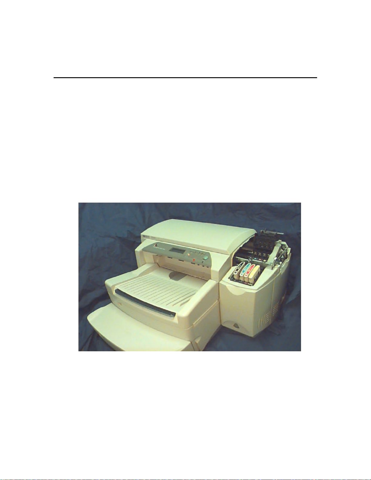
HP 2500C Series Printer
Service Manual
Page 2

ii
Version History
Version 2.0 January 1, 1999
Notice
The information contained in this document is subject to change without notice.
Hewlett-Packard makes no warranty of any kind with regard to this material,
including, but not limited to, the implied warranties of merchantability and fitness
for a particular purpose.
Hewlett-Packard shall not be liable for errors contained herein or for incidental or
consequential damages in connection with the furnishing, performance or use of this
material.
No part of this document may be photocopied, reproduced, or translated to another
language without the prior written consent of Hewlett-Packard Company.
Page 3

iii
Contents
Chapter 1
Production Information
Technology Update......................................................... ...............1-1
Modular Ink Delivery System ................................... ...............1-1
Specifications .................................................................................1-4
Data Sheet ................................................................................1-4
Cable Specifications..................................................................1-8
Reliability Specifications ..........................................................1-14
Interface Specifications.............................................................1-15
Physical Specifications..............................................................1-16
Packaging Dimensions Specifications .......................................1-17
Electrical Specifications............................................................1-18
Environmental Specifications ....................................................1-19
Product Certifications................................................................1-20
Media Sizes Supported..............................................................1-21
Recommended Media Weight...................................................1-22
Paper Handling .........................................................................1-23
Printable Area...........................................................................1-24
Media Margins ..........................................................................1-25
Hewlett-Packard Ink Cartridge Specifications...........................1-27
System Requirement.................................................................1-28
Product Overview...........................................................................1-29
Printer External View................................................................1-29
Model and Serial Number .........................................................1-29
Supplies and Accessories................................................................1-30
Product Structure......................................................................1-30
Power Cord ...............................................................................1-31
Network Interface .....................................................................1-32
Print Cartridge ..........................................................................1-33
Media........................................................................................1-34
Other Accessories .....................................................................1-35
Replaceable Parts......................................................................1-35
Warranty and Support.....................................................................1-36
Hewlett-Packard Limited Warranty Statement...........................1-37
Extent of Limited Warranty.......................................................1-37
Limitations of Warranty............................................................1-38
Limitations of Liability .............................................................1-39
Obtaining Printer Drivers..........................................................1-40
Service Support Contracts.........................................................1-41
Service and Support Resource ...................................................1-42
Worldwide Customer Support Numbers....................................1-49
Page 4

iv
Chapter 2
Operating Overview
Using the Control Panel................................................................... 2-1
Control Panel Layout................................................................. 2-1
Indicator Lights.......................................................................... 2-3
Settings and Defaults ................................................................. 2-4
Restoring Factory Defaults ......................................................... 2-7
Control Panel Menus.................................................................. 2-8
Paper Handling Menu........................................................... 2-9
Diagnostics Menu................................................................2-11
Information Menu ...............................................................2-12
Self-Test Menu....................................................................2-13
Print Quality Menu..............................................................2-14
Printing Menu .....................................................................2-15
I/O Menu.............................................................................2-16
Resets Menu........................................................................2-17
Configuration Menu............................................................2-17
MIO Menu..........................................................................2-18
Aligning Printheads...................................................................2-19
Printhead Diagnostic Process....................................................2-20
Error Codes ....................................................................................2-21
Recoverable Error Codes................................................................2-21
Unrecoverable Codes..................................................................2-23
Printer Diagnostic Pages.................................................................2-33
Diagnostic Page...........................................................................2-33
Extended Diagnostic Page............................................................2-35
Page 5

v
Chapter 3
Loading Paper and Paper Behavior
Chapter 4
Install / Uninstall
Loading the Trays............................................................................ 3-1
Loading Commonly-Used Media in Tray 2...................................... 3-2
Loading Commonly Used Media in Tray 3 ...................................... 3-4
Loading Paper in Tray1.................................................................... 3-6
Loading Paper through the Rear Manual Feed.................................. 3-7
Paper Behavior ................................................................................ 3-8
Print Job Selected Tray 2 .............................................................. 3-8
Print Job Selected Tray 3 .............................................................. 3-8
Print Job Selected Autoselect........................................................ 3-9
Print Job Selected Manual Feed .................................................... 3-9
Unexpected Paper Size.................................................................. 3-9
Printer is Idle ................................................................................ 3-9
Printer is Printing from Tray 1 or Tray 2....................................... 3-9
Printer is Printing from Tray 3 .....................................................3-10
Paper Jam at Output Bin During Paper Loading...........................3-10
Paper Jam at Output Bin During Printing.....................................3-10
Paper Jam Internal During Paper Loading....................................3-11
Installing Printer Software from CD................................................. 4-1
Installing PCL Software from CD in Windows ................................ 4-2
Installing PCL Software from Floppy Diskettes in Windows......... 4-3
Installing PostScript Software in Macintosh.................................. 4-4
Installing PostScript Software in Windows ................................... 4-4
Uninstalling Printer Software ........................................................... 4-5
For Windows 3.1x ........................................................................ 4-5
For Windows 95 / 98 / NT4.0 ....................................................... 4-5
Copy Printer Software from CD to Disk or Server ........................... 4-6
Page 6

vi
Chapter 5
Maintenance and Ink Cartridge Safety
Chapter 6
Functional Overview
Cleaning the Printer and Accessories ............................................... 5-1
Cleaning Spilled Ink ..................................................................... 5-1
Printhead ...................................................................................... 5-2
Ink Cartridge Safety ......................................................................... 5-3
For HP No.10 Color/Black Ink Cartridges..................................... 5-3
For Service Station Assembly ....................................................... 5-5
Potential Health Effects ................................................................ 5-6
First Aid Measures ........................................................................ 5-7
Note to Physician.......................................................................... 5-7
Handling Precautions.................................................................... 5-7
Additional Information ................................................................. 5-8
Material Safety Data Sheet (MSDS).............................................. 5-8
Writing System................................................................................ 6-1
Introduction.................................................................................. 6-1
Part Numbers................................................................................ 6-2
Ink Cartridge and Printhead Specifications.................................... 6-3
Thermal InkJet Technology........................................................... 6-4
Paper Paths and Components........................................................... 6-6
Chassis.......................................................................................... 6-6
Output Management ..................................................................... 6-7
Output Mechanism........................................................................ 6-8
Swivel PCA.................................................................................6-18
Dual Bin Pick and Feed Mechanism.............................................6-21
HP 2500C Electronics .....................................................................6-24
HP 2500C PCA Overview............................................................6-24
Motor Control Overview ..............................................................6-25
Firmware........................................................................................6-26
Physical Layer.............................................................................6-27
Data Link Layer ...........................................................................6-27
Application Layer........................................................................6-28
Interface with Mechanism............................................................6-28
Interface with Key Panel..............................................................6-29
Page 7

vii
Chapter 7
Removal and Replacement of Parts (without Calibration)
Introduction..................................................................................... 7-1
Removal and Replacement Tools.................................................. 7-1
Before You Begin......................................................................... 7-2
Important Notes about Printer Components and Disassembly ........ 7-3
Replacement of Parts....................................................................... 7-4
Removing the PCA....................................................................... 7-4
Installing the PCA......................................................................... 7-6
Removing the Service Station....................................................... 7-7
Installing the Service Stations....................................................... 7-9
Removing the LED PCA..............................................................7-10
Installing the LED PCA...............................................................7-12
Removing the LCD Panel ............................................................7-13
Installing the LCD Panel..............................................................7-14
Removing the Power Knob..........................................................7-15
Installing the Power Knob ............................................................7-16
Removing the Power Supply........................................................7-19
Installing the Power Supply .........................................................7-20
Removing the MIDS....................................................................7-21
Installing the MIDS .....................................................................7-22
Removing the Ink Supply System ................................................7-23
Installing the Ink Supply System..................................................7-24
Removing the Main Case.............................................................7-25
Installing the Main Case...............................................................7-26
Removing the Paper Knob ...........................................................7-27
Installing the Paper Knob.............................................................7-28
Removing the Fan........................................................................7-29
Installing the Fan .........................................................................7-30
Removing the Carriage Motor......................................................7-31
Installing the Carriage Motor.......................................................7-32
Removing the Assembly Harness Cover ......................................7-33
Installing the Assembly Harness Cover........................................7-34
Removing the Rear Door .............................................................7-35
Installing the Rear Door ...............................................................7-36
Removing the Encoder Strip ........................................................7-37
Installing the Encoder Strip..........................................................7-38
Removing the Primary Star Wheel...............................................7-39
Installing the Primary Star Wheel.................................................7-40
Removing the Secondary Star Wheel ...........................................7-41
Installing the Secondary Star Wheel .............................................7-42
Removing the Rubber Foot..........................................................7-43
Installing the Rubber Foot............................................................7-44
Removing the Absorbers ..............................................................7-45
Installing the Absorbers ...............................................................7-48
Page 8

viii
Chapter 8
Troubleshooting
Chapter 9
Parts and Diagrams
Troubleshooting Concepts ............................................................... 8-1
LED.............................................................................................. 8-2
Standard Procedures ..................................................................... 8-3
No Power...................................................................................... 8-4
LED or LCD.................................................................................8-6
Unrecoverable Error Messages...................................................... 8-9
Print Quality ................................................................................8-11
Broken or Missing Parts...............................................................8-12
No Pick or Multiple Pick or Other Mechanism Problems .............8-13
Troubleshooting Tools.................................................................8-14
Parts List ......................................................................................... 9-1
Parts Leveraged form HP2000C (C4503A)...................................... 9-2
Exploded Views............................................................................... 9-3
Page 9
1-1
Chapter 1 Product Information
Technology Update
Modular Ink Delivery System
A modular ink delivery system is the separation of ink cartridges and printheads into
individual, single-color components. Traditional inkjet printers use one black and one tricolor ink cartridge, each with integrated printheads. HP's modular ink delivery system
features four separate ink cartridges--one for each primary printing color--and four
corresponding long-life printheads, with tubes connecting the components. Including the
standard and high-capacity black ink cartridges, there are actually nine consumables, with
only eight used in the printer at one time.
Product Information
Page 10

1-2
Technology Update
How It Works
By separating the ink cartridge from the printheads, a modular ink delivery system allows
the ink supply to remain in a permanent, fixed position. The printheads remain attached
to the carriage and move back and forth, delivering ink to the page as the paper advances
through the printer. Each printhead and ink cartridge is embedded with a tiny memory
device called a smart chip that recognizes and stores the unique operating characteristics
of the component to create a totally integrated printing system that ensures consistent,
high-quality printing at the lowest cost available.
A unique pressurization system maintains a constant supply of ink to the printheads.
Smart chips monitor the amount of ink used by counting every drop that passes through
each printhead. When the smart chips sense more ink is needed to maintain continuous
printing, a plunger in each cartridge temporarily pressurizes the cartridges to deliver more
ink to the printheads. With the modular ink delivery system, ink supply is instantly
replenished, even at top speeds.
The new, individually replaceable printheads are designed for long life and each should
print 12,000 pages in black, 24,000 pages in color. As a result, you'll go through many
ink cartridges before the corresponding printhead will need replacement. With their
modular design, ink cartridges contain twice the ink supply of current HP cartridges, so
you'll also get longer lasting cartridges. When a component approaches the end of its
print life, the smart chip notifies the user through on-screen messages so a replacement
can be purchased prior to the part expiring.
By separating the printheads and ink cartridges, you only replace the component that is
no longer usable. Printheads can be replaced one at a time without the need for costly or
extensive servicing and aren't discarded when the ink is expended. HP printheads also use
a wet wiping system to eliminate nozzle clogging that plagues other permanent printhead
designs. Component replacement is easy. Simply pull out the used part and snap in a
replacement.
Product Information
Page 11

1-3
Technology Update
The Benefits
Cuts up to 30 percent off the printing costs of other methods
§ Modular design means only the component that is no longer useful is replaced.
§ Longer-life printheads and higher-capacity ink cartridges means less frequent
replacement.
Achieves color laser speed in a personal desktop printer
§ Printheads have 304 nozzles apiece (1,216 total, the most in the industry)
resulting in faster print speeds.
§ Prints in 1/2-inch swath as opposed to the 1/5- or 1/3-inch swaths of integrated
print cartridges.
§ Ink cartridge pressurization system keeps constant flow of ink to printhead. Smart
chips store component information and alert user to low-ink, ink-out and
printhead failure status.
Product Information
Page 12
1-4
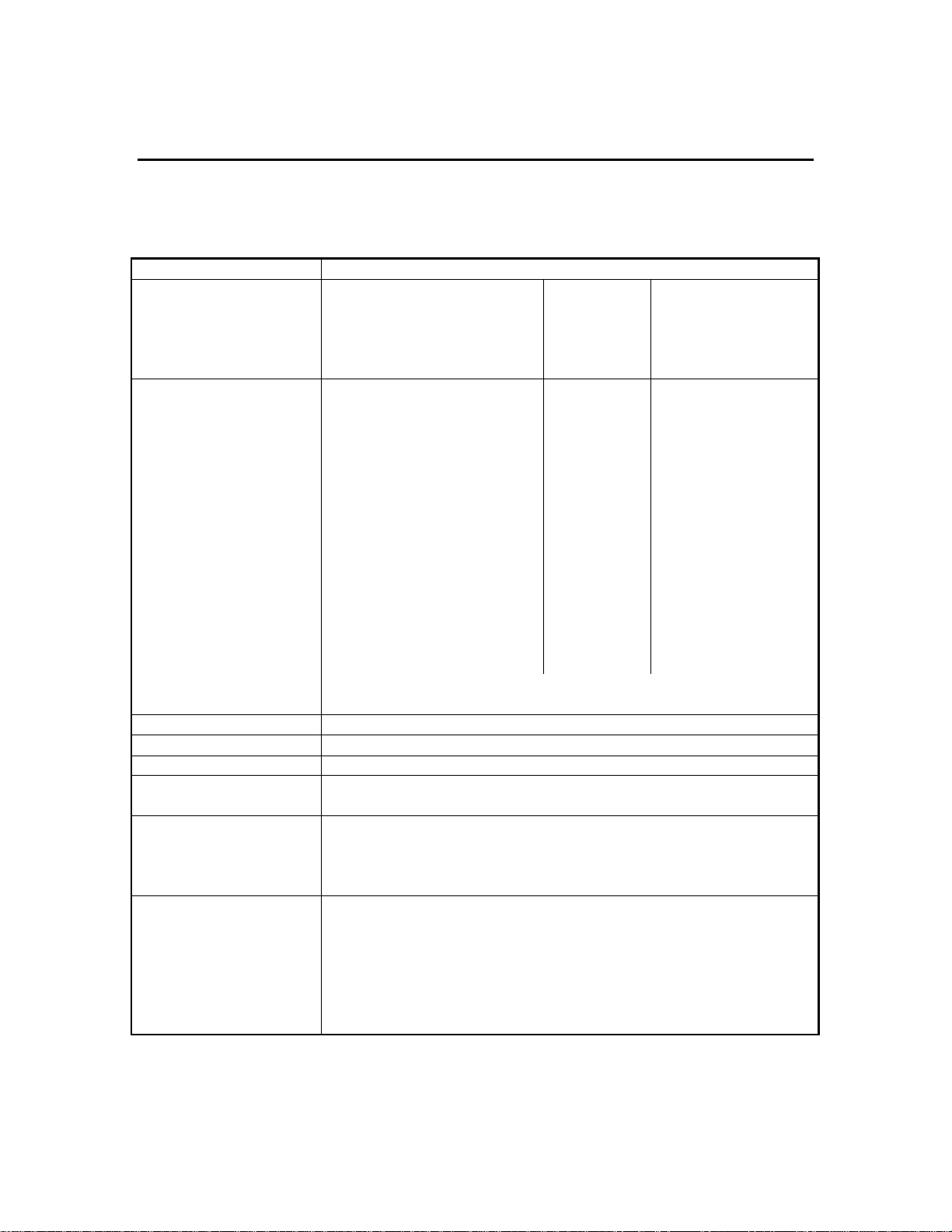
Specifications
Data Sheet
Print Method
Print Speed 1 Black Black Text
Print Speed 1 Color
Black Resolution
Color Resolution
Printhead Nozzles
Printer Command
Language
Font Capability
Memory HP 2500C
Plain paper drop on-demand thermal inkjet printing.
Econofast Mode
Normal Mode
Best Mode
Color Highlights
Econofast Mode
Normal Mode
Best Mode
Mixed Text & Graphics
Econofast Mode
Normal Mode
Best Mode
Full Page Color
Econofast Mode
Normal Mode
Best Mode
1
Approximate figures. Exact speed dependent on the system
configuration, software program, and document complexity
Up to 600x600 dpi
PhotoREt II for photo quality
304 black, 912 color (304 per color printhead)
HP PCL 3 enhanced
Adobe PostScript 3 (With HP 2500CM only)
HP FontSmart v2.5 (110 TrueType fonts for windows)
HP FontSmart software provides easy-to-use font management
capabilities
136 PostScript fonts with Adobe PostScript 3
4 Mbytes standard RAM
Letter / A4
9 ppm
7 ppm
7 ppm
Letter / A4
9 ppm
6 ppm
5 ppm
Letter / A4
7 ppm
3.5 ppm
1.2 ppm
Letter / A4
3.5 ppm
1.8 ppm
0.4 ppm
11x17 / A3
5 ppm
3 ppm
3 ppm
11x17 / A3
5 ppm
3 ppm
2 ppm
11x17 / A3
4 ppm
2 ppm
0.5 ppm
11x17 / A3
1 ppm
0.8 ppm
0.2 ppm
HP2500CM
20 Mbytes standard RAM
Two 72-pin SIMM slots for additional memory (EDO, 60ns)
expansion up to a total of 76 Mbytes
Product Information
Page 13

1-5
Connectivity /Network
Management
HP2500C
Network-capable printer for DOS and Windows environments
Enhanced HP PCL 3e Windows Driver Support for Windows NT 4.0,
Windows 3.1x/95/98
Centronics parallel, IEEE 1284 compliant
One network interface slot accepts optional HP MIO Print Servers
with support for Novell Netware, Microsoft LAN Manager, Windows
for Workgroups, Windows for NT, IBM LAN Server, Unix
environment and Apple Talk (Ether Talk)
HP2500CM
Network-ready printer for DOS, Windows and Macintosh
environments
Enhanced HP PCL 3e Windows Driver Support for Windows NT 4.0,
Windows 3.1x/95/98
Centronics parallel, IEEE 1284 compliant
HP MIO 10/100Base-TX print server with support for Novell
Netware, Microsoft LAN Manager, Windows for Workgroups,
Windows NT, IBM LAN Server, Unix environment and AppleTalk
(EtherTalk)
Supports networking protocols IPX/SPX, TCP/IP, DLC/LLC,
AppleTalk and NetBEUI
Adobe PostScript 3 drivers for Windows and Macintosh QuickDraw
Paper Handling
Automatic switching between languages and ports.
HP JetAdmin printer management software provides easy printer
setup and configuration. Latest versions available from HP’s web
site (http://www.hp.com/go/jetadmin)
HP WebJetAdmin printer management software available from HP’s
web site (http://www.hp.com/go/webjetadmin) for simple
installations and configuration from a common web browser.
Standard input capacity of 400 sheets through two trays (Tray 2 & 3)
of 150 sheet and 250 sheet capacity.
Standard output capacity of 150 sheets (face-up)
Rear Manual feed – single sheet only
Tray 1 (Input / Output Tray) – Sheets: up to 10, Cards: up to 4
Tray 2 (Upper Tray) – Sheets: up to 150, Cards: up to 60
Tray 3 (Lower Tray) – Sheets: up to 250
All input paths handle standard media sizes (as listed below) up to
13 in.x19 in. (Supper A3)
Additionally, Tray 1 and the rear manual feed support all media sizes
as small as 4 in.x6 in. (101.6mmx152.4mm)
Built-in media size sensors prevents printing on the wrong size of
media
Product Information
Page 14
1-6
Paper Size Handling
Maximum Print Width
Recommended Media
Weight
Minimum Width: 76.2 mm (4in.) x 127.0 mm (6 in.)
Maximum Width: 330.2 mm (13in.) x 482.6 mm (19 in.)
320 mm (12.61 in.) x 470 mm (18.49 in.) on 13 in. x 19 in. media
All input paths handle the following paper weights with the rear
straight-through paper path handling up to 0.3 mm thickness of paper
Paper / Labels: 60 to 135 g/m2 (16 to 36 lb. Bond)
Cards: 110 to 200 g/m2 (110 lb. Index)
Straight-through path: up to 0.3 mm thickness (0.012 in.) or approx.
200 g/m2 (110 lb. Index)
Smart Software
Features
Media Size / Type
Control Panel
Built-in printer driver features:
HP ZoomSmart scaling technology, Billboard, Handout (N-up
printing), Mirror, Watermark, Print Preview, Quick Sets, LaserJet
Margin Emulation
Paper: Super B 13 x 19 in., U.S. Tabloid 11 x 17 in.,
U.S. Legal 8.5 x 14 in., U.S. Letter 8.5 x 11 in.,
European A3 297 x 420 mm, European A4 210 x 297 mm,
European B4 257 x 364 mm
Transparencies: U.S. Letter 8.5 x 11 in., European A4 210 x 297mm
Cards: U.S. Index card 4 x 6 in., Index card 5 x 8 in.,
European A5 card 105 x 148.5 mm, Postcard 100 x 148 mm
Labels: U.S. Labels, 8.5 x 11 in.; European A4 Labels, 210 x 297mm
Intuitive operation and complete, easy-to-understand messages
Two-line 32 character LCD display and 2 LEDs
Buttons: (Go), Job Cancel, Menu, Item, Value, Select
Indicators: Attention, Ready
Operating
Environment
Power Supply
Power Requirements
Power Consumption
Product Information
Messages can be displayed in 14 languages: English, French, Italian,
German, Spanish, Portuguese, Dutch, Norwegian, Finnish, Swedish,
Danish, Polish, Czech and Russian
Operating temperature: 5o to 40oC (41o to 104oF)
Recommended operating conditions: 15o to 35oC (59o to 95oF)
Storage temperature: -40o to 60oC (-40o to 140oF)
Relative Humidity: 20 to 80% RH non-condensing
Noise levels per ISO 9614-1: Sound Pressure, LwAm 62 dB(A)
Built-in Universal Power Supply
Input Voltage 100 – 240 AC (±10%), 50/60 Hz (±3 Hz)
Less than 2 watts when off, 8 watts maximum non-printing, 35 watts
average printing, 65 watts maximum printing
Page 15

1-7
Dimensions
With paper tray closed
685 mm (26.97in.) W x 610 mm (24.02in.) D x 337 mm (13.27in.) H
With paper tray fully extended
685 mm (26.97in.) W x 745 mm (29.33in.) D x 337 mm (13.27in.) H
Desk Space Required
685 mm (26.97 in.) W x 532 mm (20.94 in.) D
Weight
Reliability & Estimated
Usage
System Requirements
Warranty
Product Certifications
26.5 kg (58.48 lb.) without printheads and ink cartridges
27.0 kg (59.52 lb.) with printheads and ink cartridges
Up to 12,000 pages / month
Minimum:
Recommended:
50 Mb Free HardDisk space for 11 x 17 or A3 size printing.
Graphics intensive files may require more disk space.
1 year on site warranty
Safety Certifications: CCIB (China), CSA (Canada), PSB (Singapore),
UL (USA), NOMi(Mexico), TUV-GS (Germany), SABS (South
Africa), JUN (Korea)
EMI Certifications: FCC Part 15B Class B when used with a Class B
computing device (USA), FCC Part 15B Class A when connected to
Local Area Network (LAN) Devices, CTICK (Australia & New
Zealand), VCCI (Japan), CE (European Union), B mark (Poland), Gost
(Russia), BCIQ (Taiwan), RRL (Korea)
Windows 3.1x: 486DX-66, 8Mb RAM
Windows 95/98: 486DX-100, 8Mb RAM
Windows NT 4.0: 486DX-100, 16Mb RAM
Macintosh System 7.5.3: 68040 – 8Mb RAM
Windows 3.1x: Pentium 150/166, 16Mb RAM
Windows 95/98: Pentium 150/166, 16Mb RAM
Windows NT 4.0: Pentium 150/166, 32 Mb RAM
Macintosh System 8 or later: Power PC – 16 Mb
Brands and product names listed are trademarks or registered trademarks of their
respective companies.
Information in this document is subject to change without notice – for more information
or the latest updates, please go to the HP2500C/CM’s web site located at
http://www.hp.com/go/hp2500
Product Information
Page 16
1-8
Specifications
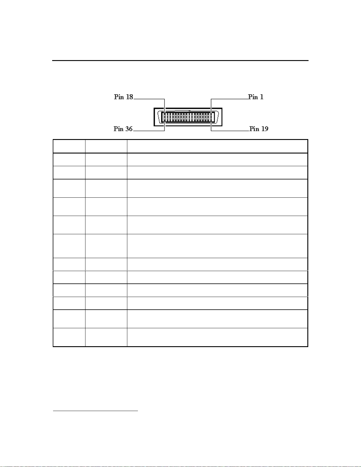
Cable Specifications
1284-B Connector Pin Assignments
The pin numbers and their assigned signal names for the 1284-B connectors are given
below.
Note
The abbreviations used in the "Source" column:
H = host; P = printer; Bi-Di = bi-directional
PIN# SOURCE COMPATIBLE NIBBLE BYTE ECP EPP
1 H nStrobe HostClk HostClk HostClk nWrite
2 Bi-Di* Data 1 (Least Significant Bit) AD1
3 Bi-Di* Data 2 AD2
4 Bi-Di* Data 3 AD3
5 Bi-Di* Data 4 AD4
6 Bi-Di* Data 5 AD5
7 Bi-Di* Data 6 AD6
8 Bi-Di* Data 7 AD7
9 Bi-Di* Data 8 (Most Significant Bit) AD8
10 P nAck PtrClk PtrClk PeriphClk Intr
11 P Busy PtrBusy PtrBusy PeriphAck nWait
12 P PError AckDataReq AckDataReq nAckReverse User Defined 1
13 P Select Xflag Xflag Xflag User Defined 3
14 H nAutoFd HostBusy HostBusy HostAck nDStrb
15 Not Defined
16 Logic Gnd
17 Chassis Gnd
18 P Peripheral Logic High
19 Signal Ground (nStrobe)
20 Signal Ground (Data 1)
21 Signal Ground (Data 2)
22 Signal Ground (Data 3)
23 Signal Ground (Data 4)
24 Signal Ground (Data 5)
25 Signal Ground (Data 6)
26 Signal Ground (Data 7)
27 Signal Ground (Data 8)
28 Signal Ground (PError, Select, nAck)
29 Signal Ground (Busy, nFault)
Product Information
Page 17

1-9
30 Signal Ground (nAutoFd, nSelectIn, nInit)
31 H nInit nInit nInit nReverseRequest nInit
32 P nFault nDataAvail nDataAvail nPeriphRequest User Defined 2
33 Not Defined
34 Not Defined
35 Not Defined
36 H nSelectIn 1284 Active 1284 Active 1284 Active nAStrb
∗ Data signals will be driven by some but not all peripheral devices.
∗ Pins not defined by this spec are used by manufacturers at their own risk.
Product Information
Page 18
1-10
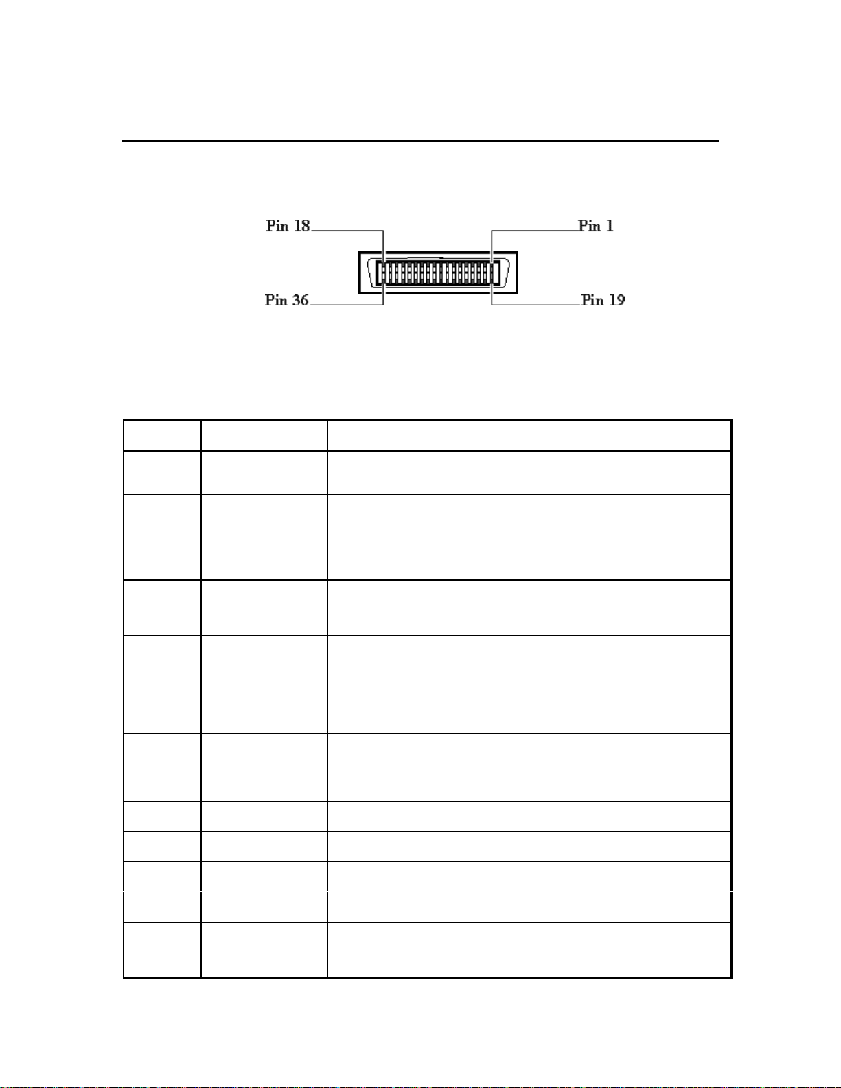
Specifications
Centronics Parallel Pinout Information
PIN NUMBER PIN ID DESCRIPTION
Clear
1
1
A low pulse causes the printer to read one byte of data
ready for more data.
receive data due to data entry, a full buffer or error status.
paper.
condition. The printer sends a low logic level to indicate that it is offline or that the
input buffer is full.
A low pulse sent by the computer resets the printer and clears the print buffer. The
reset occurs on the trailing edge of the pulse
1 Strobe
2 - 9 Data 0 - Date 7 These pins are the data lines. Data 0 is the least significant bit (LSB)
10 Acknowledge The printer sends a low pulse to indicate that it has accepted a byte of data and is
11 Busy The printer sends a high logic level to indicate to the computer that it cannot
12 Paper Error The printer sends a high logic level to indicate to the computer that it is out of
13 Ready The printer sends a high logic level to indicate to the computer that it is in an online
16 Signal Ground Signal interface ground.
17 Chassis Ground Chassis ground.
18 +5 V The printer outputs a +5 volt high logic level through a 2.2K ohm resistor.
19 - 30 Ground These pins are tied to signal ground
31 Reset/Input
32 Error
1
The printer sends a low logic level to the computer to indicate that it is in an error
state.
1
Active low
Product Information
Page 19

1-11
Specifications
The Centronics Parallel Cable has only 8 data lines, 5 status lines, 4 ground lines and
ground connections between the host PC and the peripheral. Each of the signal lines has a
corresponding bit position in a memory address (register) in the host where data is read or
written. Sending data to the printer follows the sequence below:
§ Host places data in Data Out register
§ Host sends pulse on Strobe line
§ Printer sends pulse on Busy in response to pulse on Strobe
§ Printer reads data on Data Out lines
§ Printer sends pulse on ACK (Acknowledge) line after data is read
This method of data transfer is also known as the Compatibility mode and the transfer
rate of data is slow. The printer while operating in compatibility mode is capable of
indicating limited printer error feedback to the host computer. Such feedback includes:
§ Paper jam
§ Out of paper
§ Printer on or off line
§ Time out
Product Information
Page 20
1-12
Specifications
IEEE 1284 Pinout Information
Any standard IEEE 1284 compliant printer cable will work with the printer. The
customer can order the HP IEEE 124 Compliant Parallel Interface Cable C2950A (2
meters) or C2951A (3 meters). See Ordering Parts in Chapter 12 for ordering
information.
PIN NUMBER PIN ID DESCRIPTION
1 HostClk Used in a closed-loop handshake with PeriphAck to transfer data or address
2 - 9 AD1 - AD8 Host to peripheral device or peripheral device to host address or data. Data 1 is
10 PeriphClk Used in a closed-loop handshake with HostAck (nAutoFd) to transfer data from
11 PeriphAck The peripheral uses this signal for flow control in the forward direction.
12 nAckReverse The peripheral drives this signal low to acknowledge nReverseRequest. The
13 Xflag This is used by the peripheral device to reply to the requested extensibility byte
14 HostAck The host drives this signal for flow control in the reverse direction. It is used in
16 Logic Ground Logic board ground.
17 Chassis Ground Chassis Ground.
information from the host to the peripheral device.
the least significant bit (bit 0).
the peripheral device to host.
PheriphAck also provides a ninth data bit to determine whether command or
data information is present on the data signals in the reverse direction.
host relies upon nAckReverse to determine when it is permitted to drive the
data signals.
during the negotiation phase.
an interlocked handshake with PeriphClk. Host Ack also provides a ninth data
bit used to determine whether command or data information is present on the
data signals in the forward direction.
18 Peripheral Logic High This signal is used to provide +5V high logic.
19-30 Ground These pins are tied to signal ground
31 nReverseRequest This signal is driven low to place the channel in the reverse direction. While in
ECP mode, the peripheral is only allowed to driver the bi-directional data
signals when nReverseRequest is low and 1284 Active is high.
Product Information
Page 21

1-13
32 nPeriphRequest During ECP mode the peripheral may drive this pin low to request
communications with the host. This request merely “hints” to the host; the host
has ultimate control over the transfer direction. This signal provides a
mechanism for peer-to-peer communication. This signal is valid in the forward
and reverse directions.
36 1284 Active Driven high by host while in ECP mode. Set low by the host to terminate ECP
mode and return the link to the Centronics (uni-directional) mode
The 1284 compliant cable supports the ECP (Extended Capabilities Port) mode in the
transfer of data. The ECP protocol includes a series of protocols that differ from standard
Centronics parallel port operation. These additional signaling methods allow the host and
peripheral to negotiate any of faster transfer modes (e.g. DMA, FIFO and RLE
decompression). The protocol is hardware driven and the performance is limited by the
ISA bus bandwidth. The primary advantage is that once data transfer is negotiated, data
can flow without the need of an acknowledge or a return status signal. This can result in a
transfer rate of up to 10 times faster than that of the compatibility mode that the
Centronics parallel cable supports.
To transfer data, the host first goes through a negotiation phase, which allows the host
and peripheral to select a mutually-supported communications mode. During the
negotiation phase, the host indicates which communication mode and options it would
like to use via the Extensibility Request Value. If the peripheral device does not support
the requested mode or options, it sets the Extensibility Flag low and the interface returns
to Compatibility Mode.
Product Information
Page 22

1-14
Specifications
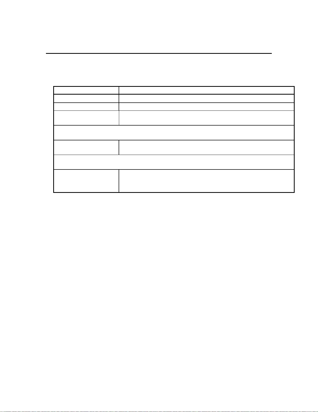
Reliability Specifications
Category Specifications
Printer Usage Up to 12,000 pages / month
Mechanism Life 150,000 A size pages / 5 years
Product Information
Page 23

1-15
Specifications
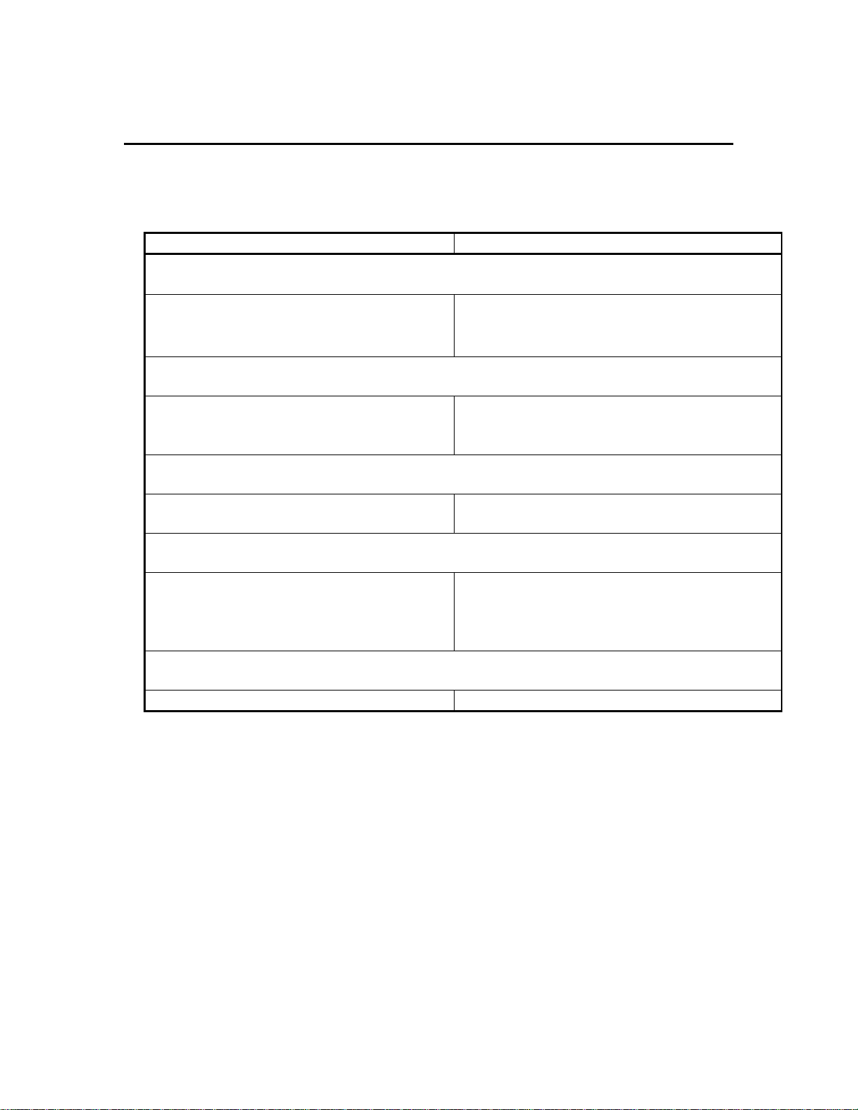
Interface Specifications
Category Specifications
Interface Specification
§ Centronics parallel, IEEE 1284
Compliant with 1284-B
receptacle (ECP)
§ 64KB buffer size
Product Information
Page 24
1-16
Specifications
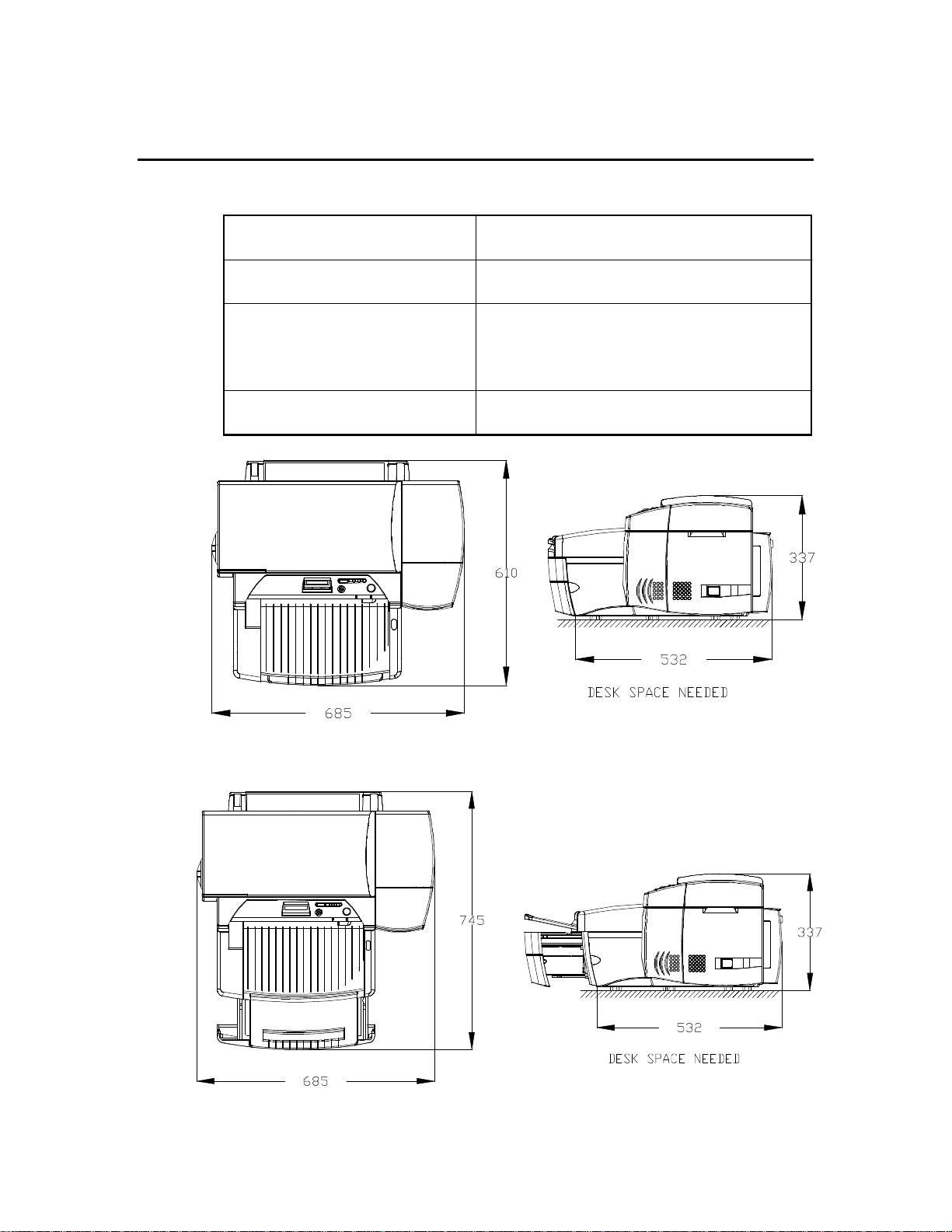
Physical Dimensions
With paper tray closed
(W x D x H)
With paper tray fully extended
(W x D x H)
Weight 26.5 kg (58.48 lb.) without printheads and
Desk space needed
(W x D)
27.0 x 24.0 x 13.3 inches
685 x 610 x 337 mm
27.0 x 29.3 x 13.3 inches
685 x 745 x 337 mm
ink cartridges
27.0 kg (59.52 lb.) with printheads and
ink cartridges
27.0 x 21.0 inches
685 x 532 mm
Product Information
Printer with paper tray closed
Printer with paper tray fully extended
Page 25
1-17
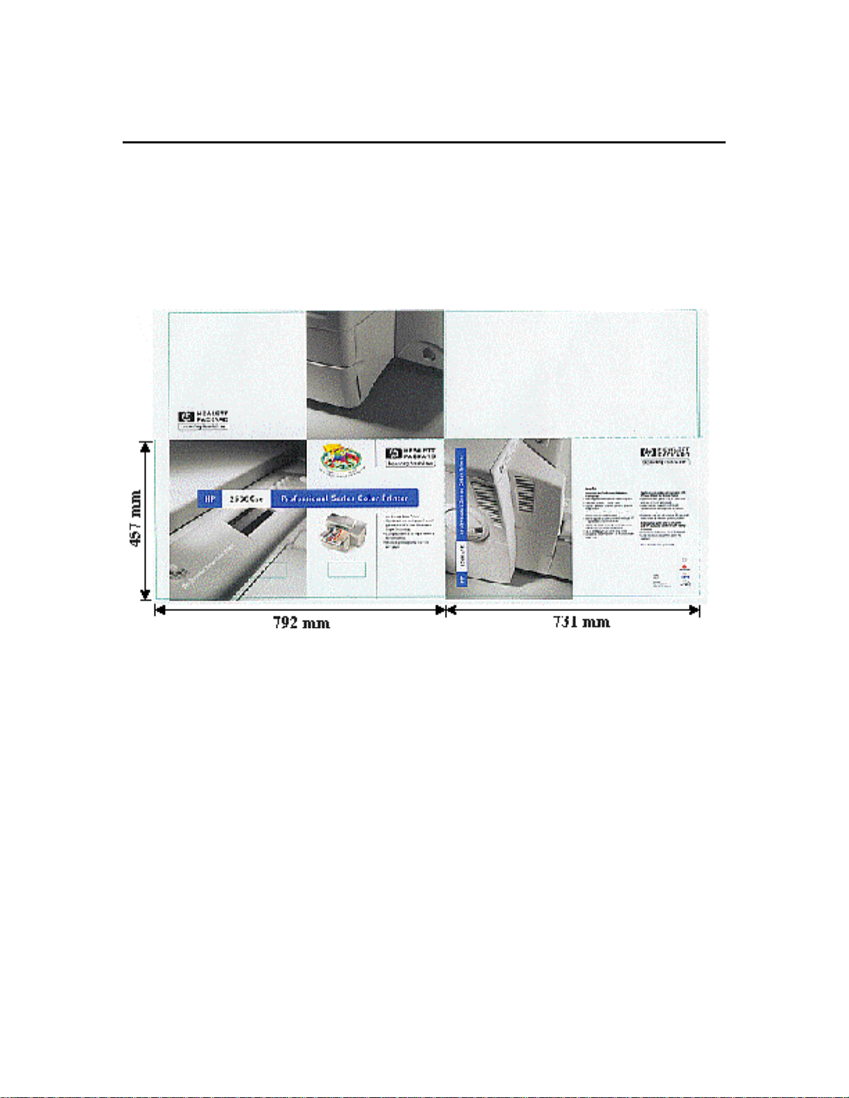
Specifications
Packaging Dimensions Specifications
792 mm (31.3 in.) W x 731 mm (28.8 in.) D x 457 mm (18.0 in.) H
Product Information
Page 26
1-18
Specifications
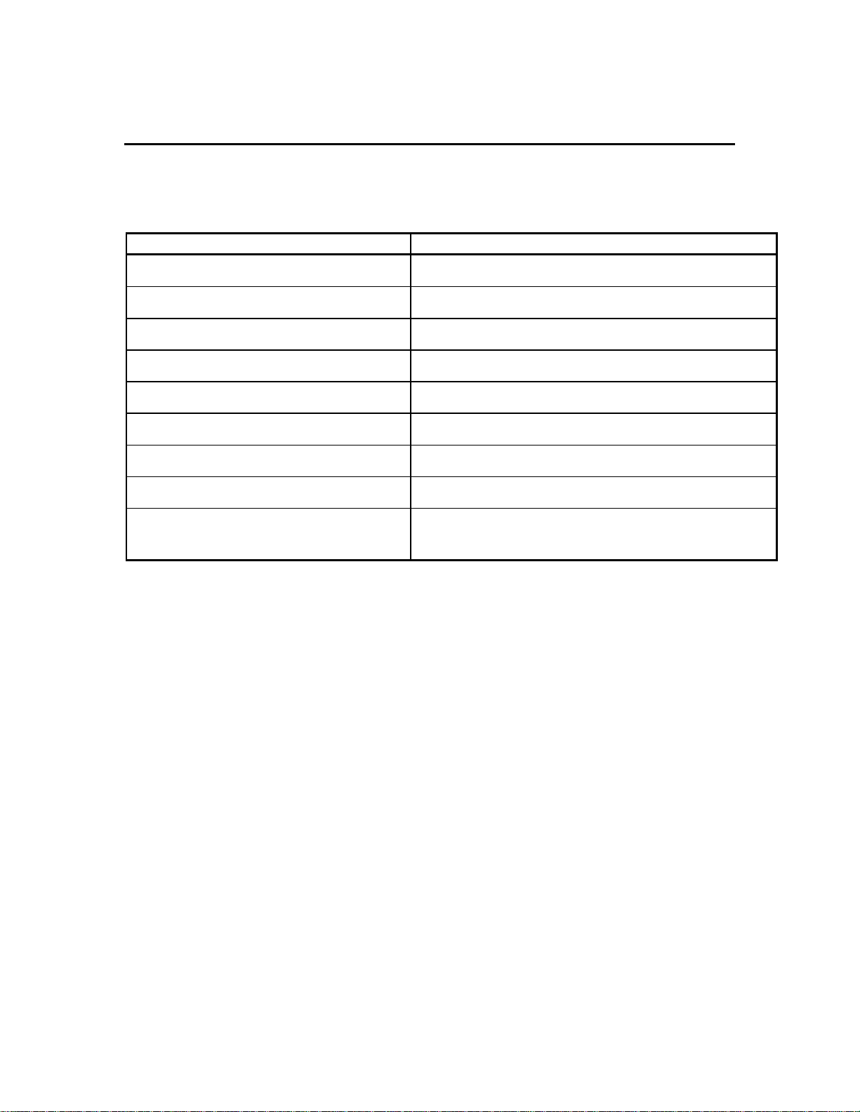
Electrical Specifications
Category Specification
Input Voltage
Frequency
Interface
Specification
Power Consumption
§ Idle
§ Printing
Transient Spike Immunity
§ Amplitude
§ Pulse width
§ Rise time
100 to 240 Vac (±10%)
50/60 Hz (±3 Hz)
Centronics parallel,
IEEE 1284 Compliant with 1284-B receptacle (ECP)
4.4 watts
35 watts max.
1 kV
50 µseconds
1.2 µseconds
Product Information
Page 27
1-19
Specifications
Environmental Specifications
Category Specifications
Temperature
§ Operating
§ Storage condition
§ Recommended operating
Humidity
§ Operating
§ Storage condition
§ Recommended operating
Altitude
§ Operating
§ Non-operating
5 °C to 40 °C (41 °F to 104 °F)
-40 °C to 60 °C (-40 °F to 140 °F)
15 °C to 35 °C (59 °F to 95 °F)
10%-80% RH non-condensing
10%-80% RH non-condensing
20%-80% RH non-condensing
0 to 3100 meters
0 to 4600 meters
Mechanical Vibration
§ Frequency range
§ Operating (Random)
§ Non-operating (Random)
§ Swept Sine
Noise Levels per ISO 9296
§ Sound power L
pAm
5 to 500 Hz
Approximately 0.21 G rms
Approximately 2.09 G rms
0.5 (0 to peak)
49 dB(A) (By-stander position)
Product Information
Page 28
1-20
Specifications
Product Certifications
Safety Certifications EMI Certifications
CCIB (China) C TICK (Australia and New Zealand)
CSA (Canada) VCCI (Japan)
NOM1 (Mexico) CE (European Union)
PSB (Singapore) GOST (Russia)
TUV-GS (Germany) B mark (Poland)
UL (USA) GOST (Russia)
SABS (South Africa) BCIQ (Taiwan)
JUN (Korea) RRL (Korea)
EMI FCC Class B when used with a Class B computing
device (USA)
Product Information
Page 29
1-21
Specifications
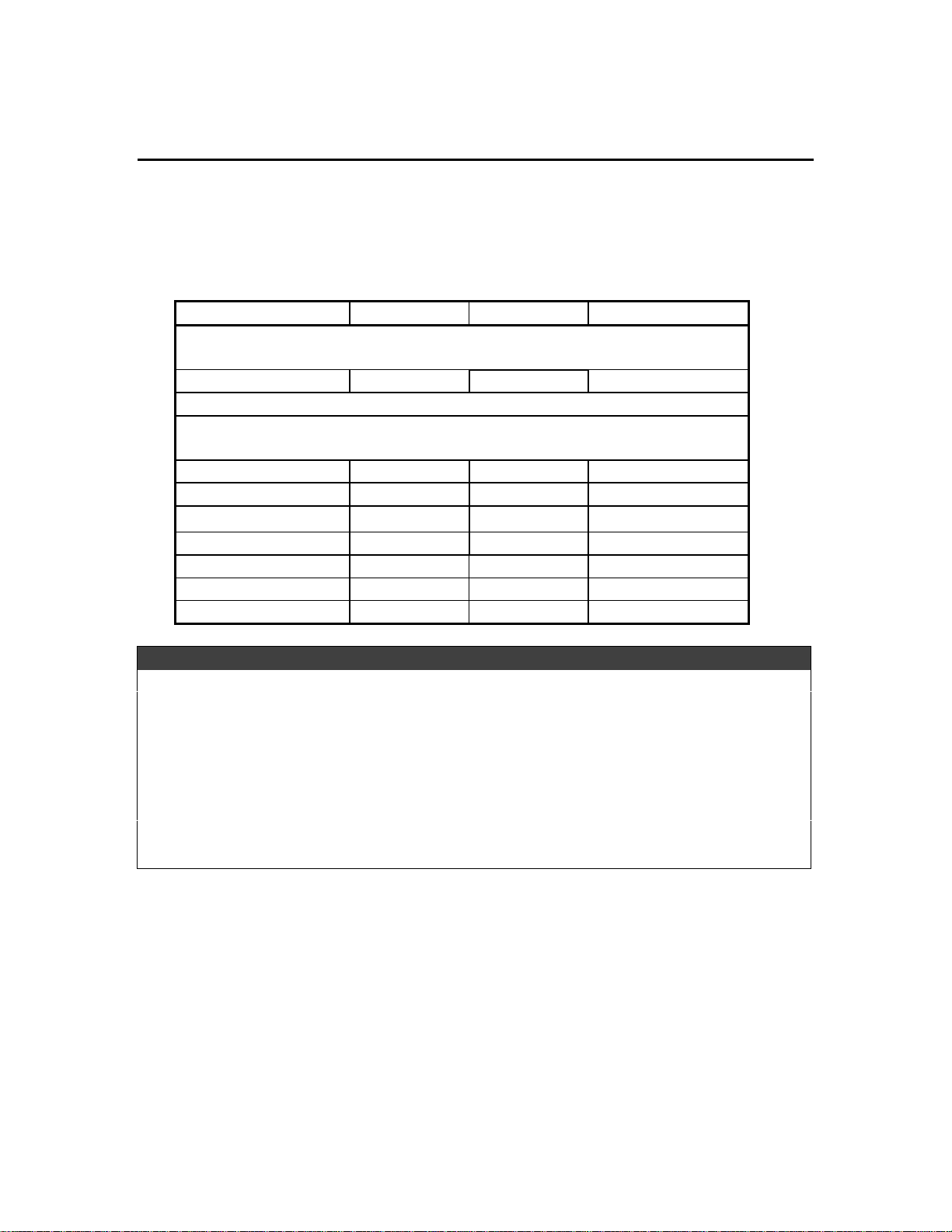
Media Sizes Supported
The following are the media sizes supported by the printer.
General type Sizes (mm) Sizes (inch) Remarks
Tray 1 (Input / Output Tray)
Post Card 100x148 3.94x5.83 Minimum Size
Including all media sizes in Tray 2 (Upper Tray) / Tray 3 (Lower Tray)
Tray 2 (Upper Tray) / Tray 3 (Lower Tray)
ISO-A4 210x297 8.27x11.7
US-Letter 215.9x279.4 8.5x11
US-Legal 215.9x355.6 8.5x14
JIS-B4 257x364 10.11x14.33
US-B (Ledger) 279.4x431.8 11x17
ISO-A3 297x420 11.69x16.53
Super B 330.2x482.6 13x19 Maximum Size
Note
1. There are sensors mounted on Tray 2 (Upper Tray) and Tray 3 (Lower Tray) of the
printer to detect the sizes of paper in use on each tray.
2. The printer is capable of printing on custom-sized media provided that its
dimensions conform to the minimum and maximum size definition.
3. Envelopes are not supported on the HP2500C/CM.
Product Information
Page 30

1-22
Specifications
Recommended Media Weight
Paper
Cardstock 110 to 200 g/m2 (110 lb. Index)
60 to 135 g/m2 (16 to 36 lb. Bond)
(up to 0.012 in. or 0.3 mm thickness for straight paper path)
Product Information
Page 31

1-23
Specifications
Paper Handling
Tray 1 (Input / Output Tray)
Sheets 10
Cards 4
Tray 2 (Upper Tray)
Sheets 150
Cards 60
Tray 2 (Upper Tray)
Sheets 250
Media Type Capacity (Pages)
Rear Manual Feed
All media sizes from 4x6 inches (101.6x152.4mm)
to 13x19 inches (330.2x482.6mm) and maximum
thickness of 0.3mm (0.012 inches)
Output Tray
Sheets (face-up) 150
Note
1. There is a sensor mounted on the bypass paper feed to indicate whether it is in use.
1
Product Information
Page 32

1-24
Specifications
Printable Area
Printable area
(Portrait
orientation)
The table as follows will show the minimum margin of each media type (portrait
orientation) for the HP 2500C Series Printer.
Please note that the printable area is smaller than that of HP LaserJets. However in the
HP2500C/CM printer driver software there is a new utility that can automatically adjust
the margins of LaserJet formatted documents so that they can be printed without the loss
of any formatting.
Printable area
(Landscape orientation)
Product Information
Page 33

1-25
Specifications
Media Margins (in portrait orientation)
Media Type
US Letter
8.5 x 11 in.
215.9 x 279.4 mm
Tabloid / Ledger
11 x 17 in.
279.4 x 431.8 mm
A4
8.27 x 11.69 in.
210.00 x 296.9 mm
A3
11.69 x 16.53 in.
296.9 x 419.9 mm
B4
10.12 x 14.33 in.
257.0 x 364.0 mm
Legal
8.5 x 14 in.
215.9 x 355.6 mm
Executive
7.25 x 10.50 in.
184.2 x 266.7 mm
A5
5.83 x 8.27 in.
148.0 x 210.0 mm
B5
7.16 x 10.12 in.
181.9 x 257.0 mm
4x6 Index Card
4.00 x 6.00
101.6 x 152.4
5x8 Index Card
5.00 x 8.00
127.0 x 203.2
Left Right Top Bottom Comments
0.25 in.
6.4 mm.
0.20 in.
5.1 mm.
0.13 in.
3.4 mm.
0.20 in.
5.1 mm.
0.20 in.
5.1 mm.
0.25 in.
6.4 mm.
0.25 in.
6.4 mm.
0.12 in.
3.1 mm.
0.12 in.
3.1 mm.
0.12 in.
3.1 mm.
0.12 in.
3.1 mm.
0.25 in.
6.4 mm.
0.20 in.
5.1 mm.
0.13 in.
3.4 mm.
0.20 in.
5.1 mm.
0.20 in.
5.1 mm.
0.25 in.
6.4 mm.
0.25 in.
6.4 mm.
0.12 in.
3.1 mm.
0.12 in.
3.1 mm.
0.12 in.
3.1 mm.
0.12 in.
3.1 mm.
Margins
0.12 in.
3.0 mm.
0.12 in.
3.0 mm.
0.12 in.
3.0 mm.
0.12 in.
3.0 mm.
0.12 in.
3.0 mm.
0.12 in.
3.0 mm.
0.12 in.
3.0 mm.
0.12 in.
3.0 mm.
0.12 in.
3.0 mm.
0.12 in.
3.0 mm.
0.12 in.
3.0 mm.
0.50 in.
12.7 mm.
0.50 in.
12.7 mm.
0.50 in.
12.7 mm.
0.50 in.
12.7 mm.
0.50 in.
12.7 mm.
0.50 in.
12.7 mm.
0.50 in.
12.7 mm.
0.50 in.
12.7 mm.
0.50 in.
12.7 mm.
0.50 in.
12.7 mm.
0.50 in.
12.7 mm.
Landscape
Orientation
Product Information
Page 34

1-26
A6 Card
4.13 x 5.83
105.0 x 148.0
Hagaki Card
3.94 x 5.83
100.0 x 148.0
Super B
13.00 x 19.00
330.2 x 482.6
Statement
5.50 x 8.50
139.7 x 215.9
C Size
17.00 x 22.00
431.8 x 558.8
A2
16.53 x 23.38
419.9 x 593.9
Hagaki
7.87 x 5.83
200.0 x 148.0
A3 Nobi
13.00 x 19.00
330.2 x 482.6
Custom
3.94 to 13.00 x 5.83 to 19.00
100 to 330 x 148 to 482
0.12 in.
3.1 mm.
0.12 in.
3.1 mm.
0.20 in.
5.1 mm.
0.20 in.
5.1 mm.
0.50 in.
12.7 mm.
0.50 in.
12.7 mm.
0.12 in.
3.1 mm.
0.20 in.
5.1 mm.
0.20 in.
5.1 mm.
0.12 in.
3.1 mm.
0.12 in.
3.1 mm.
0.20 in.
5.1 mm.
0.20 in.
5.1 mm.
0.50 in.
12.7 mm.
0.50 in.
12.7 mm.
0.12 in.
3.1 mm.
0.20 in.
5.1 mm.
0.20 in.
5.1 mm.
0.12 in.
3.0 mm.
0.12 in.
3.0 mm.
0.12 in.
3.0 mm.
0.12 in.
3.0 mm.
0.40 in.
10.2 mm.
0.40 in.
10.2 mm.
0.12 in.
3.0 mm.
0.12 in.
3.0 mm.
0.12 in.
3.0 mm.
0.50 in.
12.7 mm.
0.50 in.
12.7 mm.
0.50 in.
12.7 mm.
0.50 in.
12.7 mm.
0.40 in.
10.2 mm.
0.40 in.
10.2 mm.
0.51 in.
13.0 mm.
0.51 in.
13.0 mm.
0.50 in.
12.7 mm.
*NEC only
*NEC only
Note
For the printable regions of landscape orientation, just reverse the matrix on the table
above. For example, the matrix for US Letter size in portrait is 8.5 x 11 inches, so in
landscape the matrix is 11 x 8.5 inches.
Product Information
Page 35

1-27
Specifications
Hewlett-Packard Ink Cartridge Specifications
Category Specification
Type
Printhead Nozzles
Black Resolution
Color Resolution
Ink Drop Volume
Print Speed1 Black Black Text
Plain paper drop on-demand thermal inkjet printing
304 black, 912 color (304 per color printhead)
Up to 600x600 dpi
PhotoREt II for photo quality
35ng black, 8ng color drop volume for high resolution printing
Econofast Mode
Normal Mode
Best Mode
Letter / A4
9 ppm
7 ppm
7 ppm
11x17 / A3
5 ppm
3 ppm
3 ppm
Print Speed1 Color
Color Highlights
Econofast Mode
Normal Mode
Best Mode
Mixed Text & Graphics
Econofast Mode
Normal Mode
Best Mode
Full Page Color Highlights
Econofast Mode
Normal Mode
Best Mode
1
Approximate figures. The exact speed is dependent on the
Letter / A4
9 ppm
6 ppm
5 ppm
Letter / A4
7 ppm
3.5 ppm
1.2 ppm
Letter / A4
3.5 ppm
1.8 ppm
0.4 ppm
11x17 / A3
5 ppm
3 ppm
2 ppm
11x17 / A3
4 ppm
2 ppm
0.5 ppm
11x17 / A3
1 ppm
0.8 ppm
0.2 ppm
system configuration, software program and document
complexity.
Product Information
Page 36

1-28
Specifications
System Requirement
The following CPUs and memory are required :
Minimum: Windows 3.1x: 486DX-66, 8 Mb RAM
Windows 95/98: 486DX-100, 8 Mb RAM
Windows NT 4.0/5.0: 486DX-66, 16 Mb RAM
Macintosh System 7.5.3 or later: 68040 – 8 Mb RAM
Recommended: Windows 3.1x: Pentium 150/166, 16 Mb RAM
Windows 95/98: Pentium 150/166, 16 Mb RAM
Windows NT 4.0/5.0: Pentium 150/166, 32 Mb RAM
Macintosh System 8 or later: Power PC – 16 Mb RAM
50 Mb free hard disk space for 11x17 or A3 size printing.
Graphics intensive files may require more disk space.
Product Information
Page 37

1-29
Product Overview
Printer External View
Model and Serial Number
The serial number of the HP 2500C Series Printers can be found on the labels at the back
of each printer and at the top of the main case (concealed by the top cover). The figure
below shows how the serial number is interpreted.
Serial Number = CCYMDVL###
CC (Country) The country show where the printer was manufactured.
Y (Year) The year the printer was manufactured.
M (Month) The month the printer was manufactured.
D (Day) The day the printer was manufactured.
V (Version) The printer model version 1 indicates HP 2500C, other version numbers
will be assigned as needed. Contact a technical support engineer if you
need to know which version a new number refers to.
L (Line) The factory assembly line which manufactured this printer.
### These three digits allow a maximum of 27,000 unique serial numbers per
line per day. This unit number is in base 30.
Product Information
Page 38

1-30
Supplies and Accessories
Product Structure
The following items will be shipped in the box:
Basics
Printer
Extended Tray Cover (a)
Driver Kit
Starter CD (b)
HP JetDirect CD (HP 2500CM printer only)(b)
User’s Guide (d)
Hardcopy Kit
Setup Poster (c)
Getting Started Guide (Not available in U.S.)
Quick Reference Guide (e)
User’s Guide (Available in U.S. only)
Accessory Kit
Power Cord (f)
Four HP No. 10 Ink Cartridges (h)
(Black, Cyan, Magenta and Yellow)
Four HP No. 10 Printheads (g)
(Black, Cyan, Magenta and Yellow)
Product Information
Page 39

1-31
Supplies and Accessories
Power Cord
US 8120-6805 #ABB, #ABM, #AC4, #AKY, #A2L, #ABA
Europe 8120-6802 #ABS, #AKB, #ACB, #ABT, #AKC, #ACT,
#AB7, #ABB, #ARG, #ARP, #AKY
Australia 8120-6803 #ABG, #AKY
Singapore / Malaysia 8120-6809 #AB4
SA 8120-6808 #ACQ
UK 8120-6801 #ABU
Product Information
Page 40

1-32
Supplies and Accessories
Network Interface
The following cards have been tested with the HP 2500C and HP 2500CM Color Printer.
JetDirect MIO print server card
(Bundled with HP 2500CM)
JetDirect MIO print server card
300X Print Server J3263A Ethernet
J4100A Ethernet
RJ-45 (10/100 base-TX)
BNC
J2556B Ethernet
RJ-45 (10/100 base-TX)
J2550B Ethernet
RJ-45 (10 Base-T)
J2552B Ethernet
BNC (Thin Coax)
RJ-45 (10 Base-T)
LocalTalk System 7
J2555B Token Ring
DB9, RJ-45
RJ-45 (10/100 base-TX)
Parallel Port
Product Information
Page 41

1-33
Supplies and Accessories
Print Cartridge
No. 10 Cyan Ink Cartridge C4841A
No. 10 Magenta Ink Cartridge C4842A
No. 10 Yellow Ink Cartridge C4843A
No. 10 Hi Capacity Black Ink Cartridge C4844A
No. 10 Cyan Pen C4801A
No. 10 Magenta Pen C4802A
No. 10 Yellow Pen C4803A
No. 10 Black Pen C4800A
Note
The HP 2500C/CM Printers are shipped with a Low Capacity Black Ink Cartridge
(C4840A).
Product Information
Page 42

1-34
Supplies and Accessories
Media
HP Bright White Paper (500 / A size) C1824A
HP Bright White Paper (500 / A4 size) C1825A
HP Bright White Paper (200 / 11x17 size) C1857A
HP Bright White Paper (200 / A3 size) C1858A
HP Premium InkJet Coated Paper (200 / A) 51634Y
HP Premium InkJet Coated Paper (200 / A4) 51634Z
HP Premium InkJet Coated Paper (100 / 11x17) C1855A
HP Premium InkJet Coated Paper (100 / A3) C1856A
HP Premium InkJet Heavyweight Paper (100 / A) C1852A
HP Premium InkJet Heavyweight Paper (100 / A4) C1853A
HP Premium Photo Paper (20 / 11x17) C6058A
HP Premium Photo Paper (20 / A3) C6059A
HP Premium Photo Paper (15 / A) C6039A
HP Premium Photo Paper (15 / A4) – European C6040A
HP Premium Photo Paper (15 / A4) – Asian C6043A
HP Premium InkJet Transparency Film (20 / A) C3828A
HP Premium InkJet Transparency Film (20 / A4) C3832A
HP Premium InkJet Transparency Film (50 / A) C3834A
HP Premium InkJet Transparency Film (50 / A4) C3835A
HP Premium InkJet Rapid-Dry Transparency Film (A) C6051A
HP Premium InkJet Rapid-Dry Transparency Film (A4) C6053A
HP Iron-On T-Shirt Transfers (10 / A) C6049A
HP Iron-On T-Shirt Transfers (10 / A4) C6050A
HP Greeting Card Paper C1812A
HP Greeting Card Paper (Europe Only) C6042A
HP White Labels 1”x2.5/8” Addressing Labels 92296A
HP White Labels 1.1/3”x4” Addressing Labels 92296B
HP White Labels 1”x4” Addressing Labels 92296C
HP White Labels 2”x4” Shipping Labels 92296D
HP White Labels 3.1/3”x4” Shipping Labels 92296E
HP White Labels 1/2”x1.3/4” Return Address Labels 92296F
HP White Labels 8.1/2”x11” White Full Sheet Labels 92296K
HP White Labels 99.1x38.1mm Addressing Labels 92296L
HP White Labels 99.1x38.8mm Addressing Labels 92296M
HP White Labels 63.5x38.1mm Addressing Labels 92296N
HP White Labels 100x51mm Addressing Labels 92296P
HP White Labels 199.6x289mm Full Sheet Labels 92296R
HP White Labels 99.1x67.7mm Parcel Labels C4296A
HP White Labels 63.5x46.6mm Addressing Labels C4297A
Product Information
Page 43

1-35
Supplies and Accessories
Other Accessories
HP 64MB (2x32MB) 60ns EDO SIMM D4543A
HP 32MB (2x16MB) 60ns EDO SIMM D3648B
HP 16MB (2x8MB) 60ns EDO SIMM D3647B
HP 2500C Postscript 3 Upgrade Kit C3289A
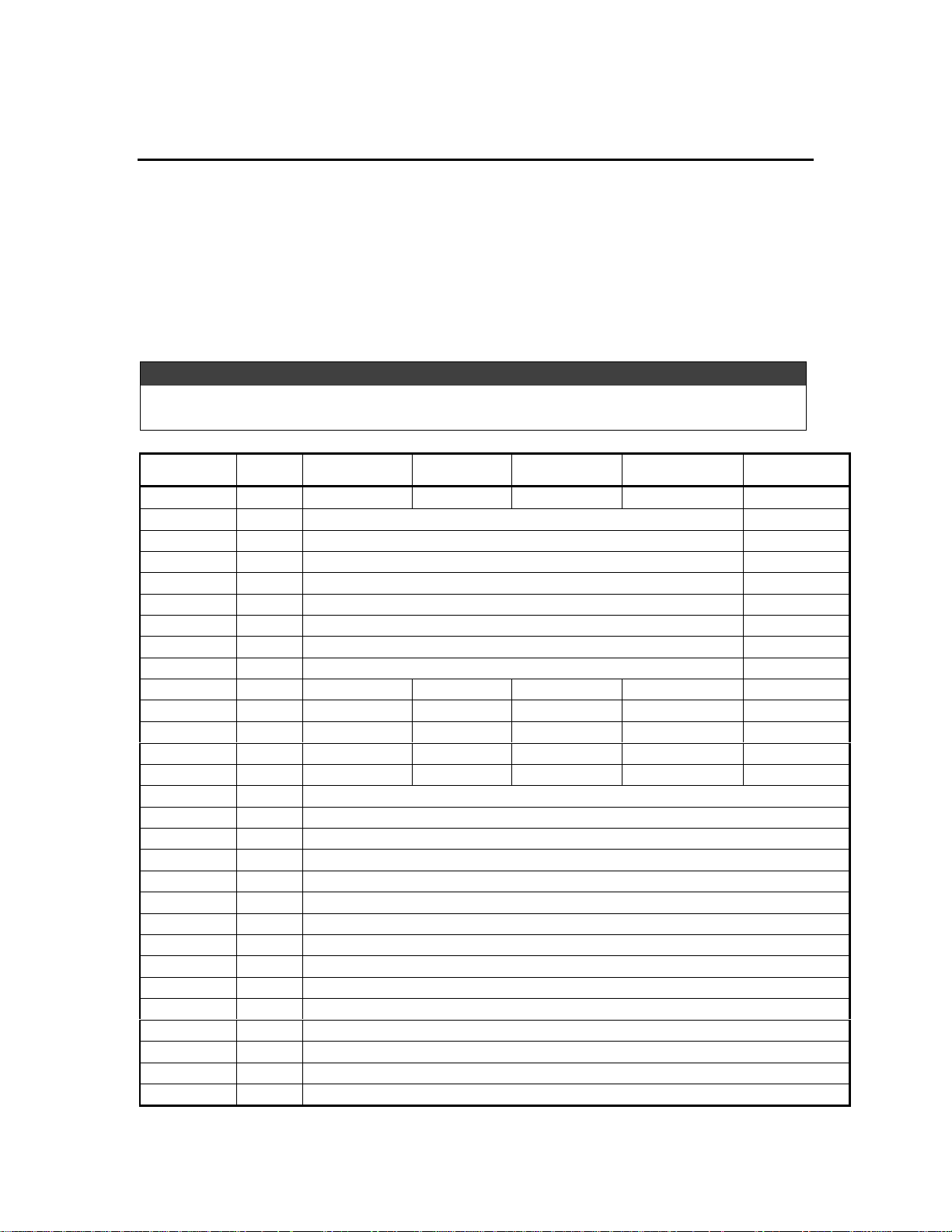
Customer Replaceable Parts
Note
The following parts are customer replaceable parts. Replacing these parts require no
technical expertise. These parts can be sent directly to the customer by the Customer
Care Centers after qualification. This process is based on the premise that customers
agree to replace the parts themselves.
The exceptions to this process are the PCA Logic and Service Station. These two parts
require some technical capability and will only be sent to customers that have the
capabilities to replace these two modules.
PCA-Logic C2684-60200
Name Plate (HP 2500C) C2684-60203
Cover Main PCA C2684-60206
Side Cover Service Station C2684-60210
Assembly Secondary Access Door C2684-60212
Assembly Output Tray C2684-60214
Removable Trough C2684-60215
Assembly Dual Bin Tray C2684-60224
Adjuster Width Dual Bin C2684-60225
Adjuster Length Dual Bin C2684-60226
Media Plate C2684-60227
Adjuster Length I/O C2684-60232
Adjuster Width I/O C2684-60233
Tray Cover C2684-60108
Cover Front C2684-60239
Service Station C2684-60273
Plate Media 2 C2684-60274
Foot C2684-60275
Product Information
Page 44

1-36
Warranty and Support
The warranty for HP 2500C Series Printers varies depending on the product, the date and
the country of purchase.
For products returned under warranty, Hewlett-Packard may :
§ Provide on-site repair,
§ Replace the product with a remanufactured unit,
§ Replace the product with a product of equal or greater functionality or
§ Refund the purchased price.
Product Information
Page 45

1-37
Warranty and Support
Hewlett-Packard Limited Warranty Statement
HP Product Duration of Limited Warranty
Software 1 year
Print Cartridges 90 days
Printer 1 year
Printheads 1 year
Extent of Limited Warranty
1. Hewlett-Packard (HP) warrants to the end user customer that HP products will be free
from defects in materials and workmanship, for a specified time after the date of
purchase by the customer. The duration of this limited warranty is stated above.
Certain additional conditions and limitations of HP’s warranty are stated in the user’s
guide. Those conditions and limitations include:
a. For software products, the warranty applies only to the media upon which the
product is recorded; and
b. HP does not warrant the operation of any product to be uninterrupted or error free.
2. HP’s limited warranty covers only those defects which arise as a result of normal use
of the product, and do not apply to any:
a. Improper or inadequate maintenance;
b. Software or interfacing not supplied by HP;
c. Unauthorized modification or misuse;
d. Operation outside the product’s environment specifications, including duty cycle
abuse or use of a mechanical switch-box without a designated surge protector;
e. Use of non-supported printing media or memory boards; or
f. Improper site preparation or maintenance.
3. For HP printer products, the use of a non-HP print cartridge or a refilled print
cartridge does not affect either the warranty to the customer or any HP support
contract with the customer; print cartridge includes both toner cartridges and ink
cartridges. However, if printer failure or damage is attributable to the use of a nonHP or refilled print cartridge, HP will charge its standard time and materials charges
to service the printer for the particular failure or damage.
4. If any software media product or print cartridge product proves defective during the
applicable warranty period, and if the product is covered by HP’s warranty, the
customer shall return the product for replacement.
Product Information
Page 46

1-38
5. If HP receives, during the applicable warranty period, notice of a defect in a hardware
product which is covered by HP’s warranty, HP shall either repair or replace the
product, at its option. Any replacement product may be either new or like-new,
provided that it has functionality at least equal to that of the product being replaced.
6. If HP is unable to repair or replace, as applicable, a defective product which is
covered by HP’s warranty, HP shall within a reasonable time after being notified of
the defect, refund the purchase price for the product, provided the customer returns
the product.
7. The warranty is valid in any country where this product is distributed by Hewlett-
Packard. Contracts for additional services such as on-site service are available from
any authorized HP service facility in countries where this product is distributed by HP
or an authorized importer.
8. This limited Warranty Statement gives the customer specific legal rights. The
customer may also have other legal rights which vary from state to state in the United
States, from province to province in Canada, and from country to country elsewhere
in the world.
Limitations of Warranty
1. NEITHER HP NOR ANY OF ITS THIRD PARTY SUPPLIERS MAKES ANY
OTHER WARRANTY OF ANY KIND, WHETHER EXPRESS OR IMPLIED,
WITH RESPECT TO HP PRODUCTS. HP AND ITS THIRD PARTY SUPPLIES
SPECIFICALLY DISCLAIM THE IMPLIED WARRANTIES OF
MERCHANTABILITY AND FITNESS FOR A PARTICULAR PURPOSE.
2. To the extent that this Limited Warranty Statement is inconsistent with the law of the
locality where the customer uses the HP product, this Limited Warranty Statement
shall be deemed modified to be consistent with such local law. Under such local law,
certain limitations of this Limited Warranty Statement may not apply to the customer.
For example, some states in the United States, as well as some governments outside
the United States (including provinces in Canada), may:
a. Preclude the disclaimers and limitations in this Warranty Statement from limiting
the statutory rights of a customer (e.g. Australia and the United Kingdom);
b. Otherwise restrict the ability of a manufacturer to make such disclaimers or
impose such limitations; or
c. Grant the customer additional warranty rights, specify the duration of implied
warranties which the manufacturer cannot disclaim, or not allow limitations on
how long an implied warranty lasts.
3. To the extent allowed by local law, the remedies provided in this Warranty Statement
are the customer’s sole and exclusive remedies.
Product Information
Page 47

1-39
Limitations of Liability
1. EXCEPT FOR THE OBLIGATIONS SPECIFICALLY SET FORTH IN THIS
WARRANTY STATEMENT, IN NO EVENT SHALL HP BE LIABLE FOR ANY
DIRECT, INCIRECT, SPECIAL, INCIDENTAL, OR CONSEQUENTIAL
DAMAGES, WHETHER BASED ON CONTRACT, TORT, OR ANY OTHER
LEGAL THEORY AND WHETHER ADVISED OF THE POSSIBILITY OF SUCH
DAMAGES.
Product Information
Page 48

1-40
Warranty and Support
Obtaining Printer Drivers
The HP 2500C Series Printer Driver Software is updated periodically. The latest versions
can be obtained from authorized Hewlett-Packard dealers or any of the sources listed
below.
24-hour Modem Access
Internet
HP 2500C Series Printer drivers and product support information can be obtained through
the World Wide Web at:
http://www.hp.com/go/hp2500
HP BBS Library
The HP 2500C Series Printer drivers can also be obtained at HP’s electronic bulletin
board library service. Refer to HP BBS Library under Service and Support
Resources for the list of phone numbers.
Set modem communications software to: no parity, 8 bits, and 1 stop bit.
Product Information
Page 49

1-41
Warranty and Support
Service Support Contracts
In the U.S.
HP SupportPack
The HP SupportPack is an enhancement to the customer’s original one-year warranty
repair service. The HP SupportPack provides next business day on-site support for the
duration of an additional two years of warranty. This service enhancement provides
customers with a cost-effective and timely way to achieve quality support. The HP
SupportPack (ordered like any other HP product) is sold exclusively through resellers and
is not available directly from Hewlett-Packard. Customers MUST purchase this service
enhancement within 30 days of purchasing the printer. The HP SupportPack is not
transferable from one piece of equipment to another. Additional information on HP
SupportPack and the prices for the service upgrade are available through HPNN and the
In-Touch newsletter.
Non-U.S.
HP SupportPack
The HP SupportPack enhances the service offering during the warranty period by
upgrading warranty repair service to a next day exchange service. This service
enhancement provides customers with a cost-effective and timely way to achieve quality
support. HP SupportPack is sold exclusively through resellers (ordered like any other HP
product) and is not available directly from Hewlett-Packard. Additional information on
HP SupportPack and the prices for the service upgrade is available through HPNN.
For other service and support contracts, contact the Hewlett-Packard office or Response
Center for that country.
Product Information
Page 50

1-42
Warranty and Support
Service and Support Resources
Hewlett-Packard News Network (HPNN)
HPNN is an electronic bulletin board service available only to HP authorized resellers.
This service provides the following information:
§ Presales Information
§ Printer Drivers
§ HP SupportPack Information
§ Software Notes
§ Postsales Information
For more information, call 1 (408) 553-7303.
HP Customer Information Center
The HP Customer Information Center provides presales product information. This
service is available for resellers and end-users.
For more information, call 1 (800) 752-0900, Monday – Friday, 6:00 AM – 5:00 PM U.S.
Pacific Time.
HP Reseller Response Line
The HP Reseller Response Line provides pre-sales and post-sales technical support for
HP authorized resellers.
For more information, call 1 (800) 544-9976, Monday – Friday, 8:00 AM – 4:00 PM U.S.
Pacific Time.
Product Information
Page 51

1-43
Warranty and Support
HP BBS Library
The HP electronic bulletin board library service, which is available 24 hours a day, 7
days a week, contains drivers and support information which can be downloaded to your
PC via modem.
Country Number Baud Rates
Austria + 43 (222)251658 2400 to 28800 or ISDN
Belgium + 32 (2) 778-3819 1200 to 28800
Denmark + 45 (45) 991905 300 to 28800
Finland (9600) 7280 2400 to 28800
France 3616 HP MICRO 1200 to 28800 (Service Minitel)
Italy + 39 (2) 9210-4244 Up to 28800
Netherlands + 31 (20) 647-5433 2400 to 28800
Norway + 47 (2) 273-5697 2400 to 28800
Sweden + 46 (8) 750-6262 2400 to 28800
Switzerland + 41 (64) 560200 Up to 28800 or ISDN
United Kingdom + 44 (1344) 361891 Up to 28800
Worldwide Int Code + 1 (208) 344-1691 300 to 28800
Set the modem for no parity, 8 data bits and 1 stop bit (N,8,1).
Product Information
Page 52

1-44
Warranty and Support
HP FAXback on Demand – HP FIRST
You can use this service to select documents, such as product descriptions and technical
information. To access this service, use the handset on your fax machine and dial the
appropriate number from the table in this section.
Use the following steps to use HP FIRST:
1. Call the system. You will need to use a touch-tone telephone or the phone set of your
fax machine. A voice prompt will welcome you and guide you to the information you
need. You will also need to give the phone number of the fax machine where you
wish to receive the documents you select.
2. We suggest you initially request the index which lists all available documents.
3. Once you receive the HP FIRST index, choose the documents you need.
4. Call HP FIRST again. A voice prompt will ask you for the index number of the
documents you have selected and would like to have faxed to you.
5. Selected documents will be sent immediately to the fax number you have specified.
Note
To obtain documents in English from outside the UK, dial your international access
code and then (31) 20 681 5792 (international toll rates applicable).
Product Information
Page 53

1-45
Warranty and Support
HP FIRST Telephone Numbers
Country Telephone Number
For US and Canada
For Customers in Europe:
U.K. 0800 96 02 71
For service in English outside U.K. + 31 20 681 5792
Austria 0600 8128
Belgium (Dutch) 0800 11906
Belgium (French) 0800 17043
Denmark 800 10453
Finland 800 13134
France 0800 905900
Germany 0130 810061
Italy 1678 59020
Norway 800 11 319
Portugal 05 05 31 33 42
Spain 900 993123
Sweden 020 795743
Switzerland (French) 0800 551 526
Switzerland (German) 0800 551 527
Netherlands 0800 022 2420
(800) 333-1917
For Customers in Asia-Pacific:
Australia 613 9272 2627
China 86 10 6564 5735
Hong Kong 2506 2422
India 9111 622 6420
Indonesia 21-352 2044
Korea 822 769 0543
Malaysia 03 298 2478
New Zealand 64 09 356 6642
Philippines (65) 275 7251
Singapore 275 7251
Taiwan (02) 719 5589
Thailand 662 661 3511
Product Information
Page 54

1-46
Warranty and Support
HP Telephone Support
Technical Phone Support for Customers
The HP Customer Support Center provides free technical assistance for peripherals
within the hardware warranty period.
For the product under warranty, call (208) 323-2551.
For the product out of warranty, call :
§ 1 (900) 555-1500 at $2.50 per minute, or
§ 1 (800) 999-1148 at $25.00 per call using VISA / MasterCard.
(The above prices are subjected to change without notice)
To ensure the call is dealt with quickly, have the following information ready:
§ The product model number and serial number.
§ The operating system version and the configuration.
§ A description of the software installed and the accessories used.
HP North American Customer Support Center
Assistance from the Hewlett-Packard North American Customer Support Center is
available Monday to Friday, 7:00 AM to 6:00 PM Mountain Time, except Wednesday,
(7:00 AM to 4:00 PM).
§ 1 (303) 635-1000
HP European Customer Support Center
Assistance from the Hewlett-Packard European Customer Support Center is available in
English, Monday to Friday, 8:30 AM to 6:00 PM Central European time, except
Wednesday, (8:30 AM to 4:00 PM).
§ Int Code + 31 (20) 682-8291
HP provides free telephone support during the warranty period. After the warranty has
expired, support is available through the same telephone number for a fee. The fee is
charged on a per incident basis. When calling HP, please have the following information
ready:
§ The product model number and serial number.
§ The operating system version and the configuration.
§ A description of the software installed and the accessories used.
Product Information
Page 55

1-47
Warranty and Support
Warranty and Out-of-Warranty Support Telephone Numbers
Country (Language) Telephone Number
Austria (German) 0660-6386
Belgium (Dutch) 02 626 8806
Belgium (French) 02 626 8807
Denmark (Danish) 3929 4099
Finland (Finnish) 0203 47288
France (French) 04 50 43 9853
Ireland 01 622 5525
Germany (German) 0180 5 25 81 43
Italy (Italian) 02 26410350
Netherlands (Dutch) 020 606 8751
Norway (Norwegian) 22 11 6299
Portugal 01 441 7199
Spain (Spanish) 902-321 123
Sweden (Swedish) 08 619 2170
Switzerland (French) 0848 80 11 11
Switzerland (German) 0848 80 11 11
UK 0171 512 5202
English language support for other European countries +44 171 512 5202
Product Information
Page 56

1-48
Warranty and Support
Contacting Hewlett-Packard
To contact HP, check your local telephone directory for the HP Sales and Service Office
near you. If you cannot find an HP office, contact one of the major HP Sales and Service
Offices or one of the following Worldwide Marketing Headquarters.
Asia Far East Sales Region Headquarters
Hewlett-Packard Asia Ltd.
22/F Peregrine Tower
Lippo Centre
89 Queensway, Central
Hong Kong
Canada Hewlett-Packard Ltd.
6877 Goreway Drive
Mississauga
Ontario L4V 1M8, Canada
Europe European Operations Headquarters
Hewlett-Packard S.A.
150, route du Nant-d’Avril
PO Box 1217
Meyrin 2/Geneva, Switzerland
Latin America Hewlett-Packard Latin Am. Headquarters
Monte Pelvoux 111
Lomas de Chapultepec
11000 Mexico D.F.
Middle East / Asia Middle East / Central Africa Sales Headquarters
Hewlett-Packard S.A.
Rue de Veyrot 39
CH-1217 Meyrin 1/Geneva, Switzerland
U.S. Intercon Operations Headquarters
Hewlett-Packard Company
3495 Deer Creek Road
PO Box 10495
Palo Alto, CA 94303-0896, USA
Product Information
Page 57

1-49
Warranty and Support
Worldwide Customer Support Numbers
Customer Support Centers provide technical information via telephone directly with
online agents who are trained to assist with setup, configuration, startup and
troubleshooting of HP products.
Customer Support Center assistance can be obtained by calling one of the following
country-specific telephone numbers:
Note
Check the world wide web at http://www.hp.com/go/hp2500 for the most up-to-date
customer support telephone numbers.
Country Telephone Number
For U.S.
For Latin America
Argentina (541) 787 4061/69
Brazil 55 11 709 1444
Chile 562 800 360999
Mexico City 01-800-22147000/1-800-9052900
Mexico Guadalajara (525) 264 2075
Mexico Monterey 91800 22147
Venezuela 582 239 5664
(208) 323-2551
Product Information
Page 58

1-50
For Europe
Africa/Middle East 41 22/780 71 11
Austria 0660 6386
Belgium (Dutch) 02 6268806
Belgium (French) 02 6268807
Czech Republic 42 (2) 471 7327
Denmark 3929 4099
Finland 203 47288
France 01 43 62 34 34
Germany 180 5258 143
Greece 0168 96 411
Hungary 36 (1) 252 4505
Ireland 01662 5525
Italy 02 264 10350
Norway 22 11 6299
Poland 48 22 37 50 65
Portugal 01 441 7199
Russia 7095 923 50 01
Spain 902 321 123
Sweden 08 619 2170
Switzerland 0848 80 11 11
Netherlands 020 606 8751
Turkey 90 1 224 59 25
United Kingdom 0171 512 5202
For Asia-Pacific
Australia (61-3) 9272-8000
China 86 10 6564 5959
Hong Kong 800 96 7729
India 9111 682 6035
Indonesia 21 350 3408
Korea (82-2) 3270-0700
Malaysia 03 295 2566
New Zealand 09 356-6640
Philippines 2 867 3551
Singapore 272 5300
Taiwan 866-2-7170055
Thailand 02 661 4011
Vietnam 8823 4530
Product Information
Page 59

Chapter 2 Operating Overview
Using the Control Panel
The Control Panel allows you to perform most major tasks with the printer, including
controlling print status, resetting from recoverable errors and changing the printer's
default settings.
Control Panel Layout
The Control Panel on the front of the printer consists of six buttons on the panel, two
LEDs and a LCD multi-function display panel:
Operating Overview 2-1
Page 60

Using the Control Panel
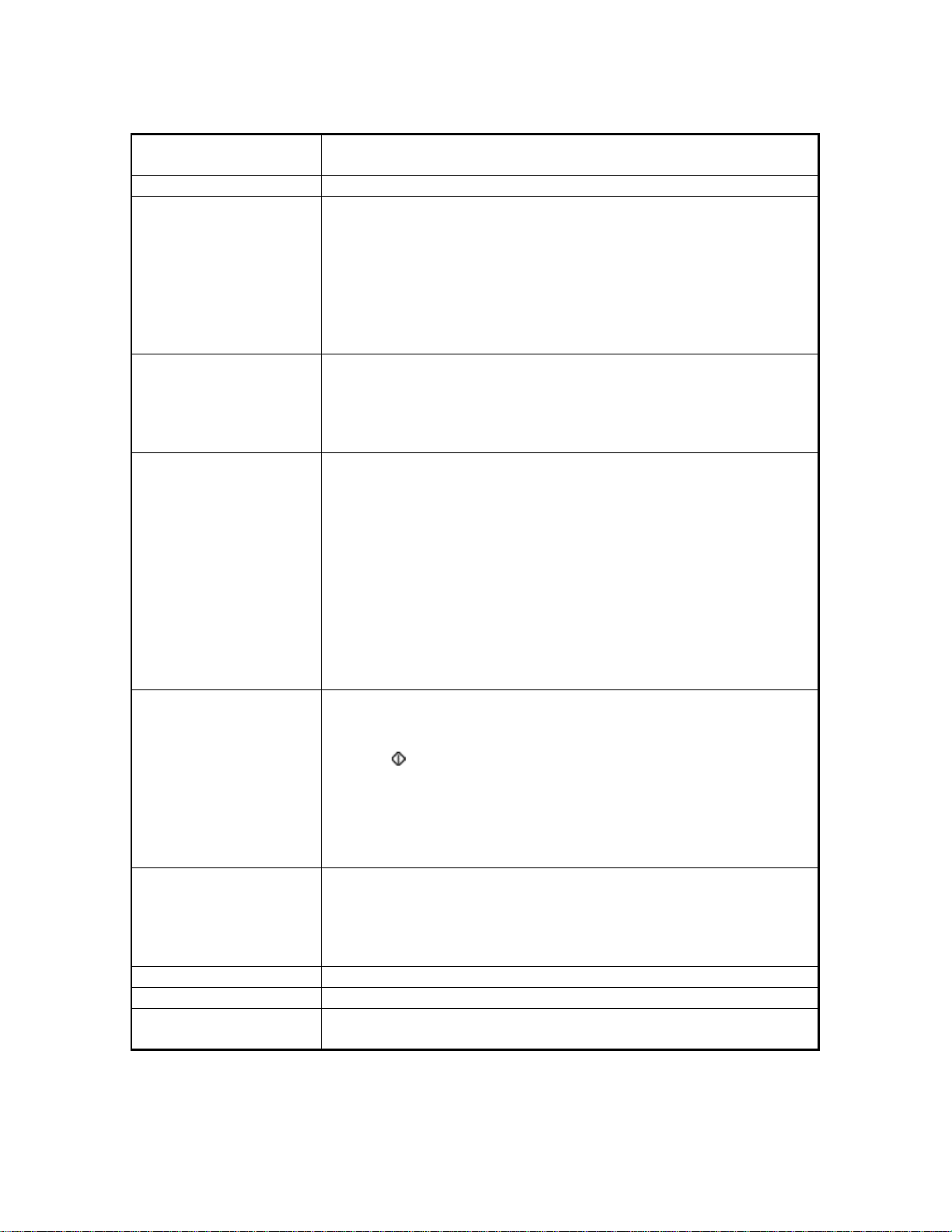
The functions of each of the buttons are as follows :
Control Panel Key Function
[ GO ]
[ Cancel Job ]
[ Menu ]
[ Item ]
[ Value ]
[ Select ]
§ Puts the printer either online or offline.
§ Allows the printer to resume printing after going
offline. Also clears most printer messages and puts
the printer online.
§ Allows the printer to continue printing after a non-
critical warning message such as UNEXPECTED
PAPER SIZE or TRAY x LOAD [ TYPE ] [ SIZE ].
§ Exits the control panel menus. (To save the control
panel selection, press the [ Select ] button first.)
§ Displays unrecoverable error codes.
Press this only once to cancel the print job that the printer
is processing. The duration required to cancel the job will
depend on the size of the print job. Pressing the Cancel
Job button repeatedly will not cancel the next job on the
print queue.
Press this to cycle through the control panel menus.
To print a menu map from the control panel :
1. Press [ Menu ] until SELF TEST MENU appears.
2. Press [ Item ] until PRINT MENU MAP appears.
3. Press [ Select ] to print the menu map.
For more information on each menu item, see Control
Panel Menus (Chapter 2).
Press this to cycle through selected menu items.
Press this to cycle through selected menu item's values.
§ Saves the value for the selected item. An asterisk (*)
will appear next to the value, indicating that it is the
new default. Default settings will remain when the
printer is powered off, or until reset when you choose
to reset factory defaults from the [ RESETS ] menu.
§ Prints the selected printer information page from the
control panel.
Operating Overview2-2
Page 61

Using the Control Panel
Indicator Lights
There are two LEDs (lights) on the printer :
LED Indicators Color Function
Ready LED Green Lit up when the printer is printing
OR in normal state
OR when it is online.
Attention LED Red Blinks when the printer is in an error state
OR requires attention.
Error LED Green + Red
blinking rapidly
Both LEDs blink when the printer detects an
error. Power cycle the printer to correct. If the
error persists, push the on-line button once to
see the error message.
Operating Overview 2-3
Page 62

Using the Control Panel
Settings and Defaults
These are the various possible menu settings. The factory defaults, where applicable, are
indicated in bold. Other additional menu items may also appear, depending on which
hardware modules have been installed in the printer.
For more information on these settings, refer to Control Panel Menus (Chapter 2).
Paper Handling Menu
TRAY 2 TYPE =
TRAY 3 TYPE =
PLAIN
HP INKJET/HEAVY
HP PHOTO
TRNSPRNCY/IRON
RAPID TRNSPRNCY
PLAIN
HP INKJET/HEAVY
HP PHOTO
TRNSPRNCY/IRON
RAPID TRNSPRNCY
Diagnostics Menu
ALIGN PRNT –HD
CLEAN PRNT -HD LEVEL 1
CLEAN PRNT -HD LEVEL 2
CLEAN PRNT -HD LEVEL 3
PERFORM TRAY2 PAPER PATH TEST
PERFORM TRAY3 PAPER PATH TEST
PERFORM TRAY1 PAPER PATH TEST
Information Menu
BASE FW VER
PS FW VER (Available if PS installed)
MIO FW VER (Available if MIO installed)
CHECK TOTAL RAM SIZE
CHECK INK LEVELS
SERVICE ID
Operating Overview2-4
Page 63

Self Test Menu
PRINT MENU MAP
PRINT PS FONT LIST (Available if PS installed)
PRINT MARKETING DEMO (Available if Demo DIMM installed)
PRINT DIAGNOSTIC PAGE
PERFORM TRAY2 PAPER PATH TEST
PERFORM TRAY3 PAPER PATH TEST
PERFORM TRAY1 PAPER PATH TEST
Print Quality Menu
PRINT QUALITY =
NORMAL
ECONOFAST
BEST
Printing Menu
PAPER =
ORIENTATION =
APPEND CR TO LF =
LETTER
LEGAL
13X19
A4
A3
11X17
JISB4
PORTRAIT
LANDSCAPE
NO
YES
I/O Menu
IN JOB TIMEOUT =
OUT JOB TIMEOUT =
I/O CHANNEL TIMEOUT =
45 (5 - 300 secs)
0 (0 - 300 secs)
0 (0 - 300 secs)
Resets Menu
RESET TO FACTORY SETTINGS
RESET ACTIVE I/O CHANNEL
RESET ALL I/O CHANNELS
RESET MIO TO FACTORY SETTINGS (Available if MIO installed)
Operating Overview 2-5
Page 64

Configuration Menu (Available if DIMM installed)
PERSONALITY =
AUTO
PCL
PS (Available if PS installed)
MIO Menu (Available if MIO installed)
CONFIGURE
MIO
(The remaining options will appear
depending on the type of MIO card installed.)
Postscript Menu (Available if PS installed)
PRINT PS ERRORS =
JAM RECOVERY =
COPIES =
OFF
ON
AUTO
ON
OFF
1 (1 – 99 pages)
Operating Overview2-6
Page 65

Using the Control Panel
Restoring Factory Defaults
To restore the default factory settings, press [ MENU ] till the Resets Menu appears. Then
press [ ITEM ] until RESET TO FACTORY SETTINGS is shown in the LCD display.
Press [ SELECT ] to restore the factory defaults. This action will also clear the input
buffer for the active I/O channel.
Operating Overview 2-7
Page 66

Using the Control Panel
Control Panel Menus
The following is a summary diagram of all the menus available in the HP 2500C series
printer :
Operating Overview2-8
Page 67

Using the Control Panel
Paper Handling Menu
Item Value Explanation
TRAY 2 TYPE=PLAIN PLAIN
HP INKJET/HEAVY
HP PHOTO
TRNSPRNCY/IRON
RAPID TRNSPRNCY
Set this value to correspond with the
paper type currently loaded in Tray 2.
PLAIN: Plain paper
HP INKJET/HEAVY: HP Premium
Inkjet Paper or HP Premium Inkjet
Heavyweight Paper
HP PHOTO: HP Premium Photo Paper
TRNSPRNCY/IRON: HP Premium
Transparency Film or HP Iron-on T-Shirt
Transfer
TRAY 3 TYPE=PLAIN PLAIN
HP INKJET/HEAVY
HP PHOTO
TRNSPRNCY/IRON
RAPID TRNSPRNCY
RAPID TRNSPRNCY: HP Premium
Inkjet Rapid-Dry Transparencies.
Note:
It is not advisable to load the following
combination of paper types in Tray 2 and Tray 3
at the same time:
§ HP Premium Inkjet Paper and HP Premium
Inkjet Heavyweight Paper
§ HP Premium Transparency Film and HP
Iron-on T-Shirt Transfer
Set this value to correspond with the
paper type currently loaded in Tray 3.
PLAIN: Plain paper
HP INKJET/HEAVY: HP Premium
Inkjet Paper or HP Premium Inkjet
Heavyweight Paper
HP PHOTO: HP Premium Photo Paper
TRNSPRNCY/IRON: HP Premium
Operating Overview 2-9
Page 68

Transparency Film or HP Iron-on T-Shirt
Transfer
RAPID TRNSPRNCY: HP Premium
Inkjet Rapid-Dry Transparencies.
Note:
It is not advisable to load the following
combination of paper types in Tray 2 and Tray 3
at the same time:
§ HP Premium Inkjet Paper and HP Premium
Inkjet Heavyweight Paper
§ HP Premium Transparency Film and HP
Iron-on T-Shirt Transfer
Operating Overview2-10
Page 69

Using the Control Panel
Diagnostics Menu
Item Explanation
ALIGN PRNT-HDS
CLEAN PRNT-HD:
LEVEL 1
CLEAN PRNT-HD:
LEVEL 2
CLEAN PRNT-HD:
LEVEL 3
PERFORM TRAY 2 PAPER
PATH TEST
PERFORM TRAY 3 PAPER
PATH TEST
PERFORM TRAY 1 PAPER
PATH TEST
This item aligns the printheads to ensure printout of the best
possible print quality.
This item cleans the printheads. Level 1 is the basic level and
should be performed first. This option will cause the printer to
perform a dry wipe and spitting.
This item cleans the printheads. Level 2 is more thorough than
Level 1, but it should be performed only when Level 1 cleaning
does not solve the print quality problem. This option will cause
the printer to perform a wet wipe, followed by a dry wipe and
spitting.
This item cleans the printheads. Level 3 is most thorough, but it
should be performed only when Levels 1 and 2 cleaning do not
solve the print quality problem, as it uses the most ink. This
option will cause the printer to perform 3 wet wipes followed
by dry wipes and spitting. The maximum amount of ink used is
less than 0.1 cc.
This item performs a paper path test on Tray 2. When this is
selected, the printer will pick paper from Tray 2 until all the
paper has been ejected.
This item performs a paper path test on Tray 3. When this is
selected, the printer will pick paper from Tray 3 until all the
paper has been ejected.
This item performs a paper path test on Tray 1. When this is
selected, the printer will pick paper from Tray 1 until all the
paper has been ejected.
Note
1. The “PRNT-HD NOT ALIGNED” message will appear if the Secondary Access Door has been
opened even though the print heads have not been changed.
Operating Overview 2-11
Page 70

Using the Control Panel
Information Menu
Item Explanation
CHECK INK LEVEL
BASE FW VER
This item displays the amount of ink remaining in each ink
cartridge. The following screen appears on the LCD:
B C M Y
60% 80% 80% 80%
B, C, M and Y represent the black, cyan, magenta and yellow
cartridges respectively. The corresponding percentage under
each letter indicates the amount of ink left (from 0% to 99%).
This item displays the firmware version of the printer. Example:
VERSION=5.10
PS FW VER
MIO FW VER
CHECK TOTAL RAM
SIZE
SERVICE ID
This item displays the PostScript firmware version of the
printer. Example:
FIRMWARE VERSION=5.10
This item displays the MIO print server firmware version.
Example:
MIO VERSION=3.10
This item displays the total amount of RAM available in the
printer. Example:
TOTAL RAM SIZE=6118K
This item displays the Service Identification Number of the
printer. This number is used by HP Customer Care Centers for
support. The format taken is:
SERVICE ID=YYDDD
Where YY indicates the last two digits of the year of
manufacture and DDD indicates the number of days since the
printer was first used by the customer.
Operating Overview2-12
Page 71

Using the Control Panel
Self-Test Menu
Item Explanation
PRINT MENU MAP
PRINT PS FONT LIST
PRINT DIAGNOSTIC PAGE
PRINT EXT DIAGNOSTIC
PAGE
The Menu Map shows the layout of the Control Panel
menu items.
The PS Font List shows all the PS fonts currently
available to the printer. This option is activated only if
PS Personality module has been installed.
The Diagnostic Page shows general printer information
and current network parameters. See Diagnostic Page
(Chapter 2).
The Extended Diagnostic Page shows printer
information which is used for troubleshooting. See
Extended Diagnostic Page (Chapter 2).
Operating Overview 2-13
Page 72

Using the Control Panel
Print Quality Menu
Item Value Explanation
PRINT QUALITY=
NORMAL
NORMAL
ECONOFAST
BEST
NORMAL: Normal mode delivers high
quality output and is the recommended setting
for speed and quality. Normal mode is the
default setting for most paper types.
ECONOFAST: Draft quality printing.
EconoFast mode prints faster than Normal
mode and delivers comparable output.
Using EconoFast will also cut down on the
frequency of replacing your ink cartridges
because it uses less ink. EconoFast printing is
available only when you select plain paper or
transparency as the paper type.
BEST: High quality printing. Best mode
produces the highest print quality for all paper
types and eliminates the banding effect that
sometimes occurs in solid areas. However,
Best mode prints more slowly than Normal
mode for most documents.
Note
2. When printing in either Normal or Econofast mode, the printer will print bi-directionally (that is,
from left to right and right to left).
3.
4. However in when printing in Best mode, the printer will print uni-directionally (that is, only from
right to left). Printing in Best mode will result in slower printing, but this can solve banding
problems.
Operating Overview2-14
Page 73

Using the Control Panel
Printing Menu
Item Value Explanation
PAPER=
LETTER
ORIENTATION=
PORTRAIT
APPEND CR TO LF=NONO
LETTER
LEGAL
13X19
A4
A3
11X17
JISB4
PORTRAIT
LANDSCAPE
YES
Sets the paper size.
Determine the default orientation of print
on the page.
Note:
It is best to set the page orientation from
the printer driver or software application.
Select YES to append a carriage return to
each line feed (LF) encountered in
backward-compatible PCL jobs (pure
text, no job control).
Some environments indicate a new line
using only the line feed control code.
This option allows the user to append the
required carriage return to each line feed.
Operating Overview 2-15
Page 74

Using the Control Panel
I/O Menu
Item Value Explanation
IN JOB TIMEOUT=
15
OUT JOB TIMEOUT=
15
5 to 300 Selects the amount of time (in seconds)
that the printer will wait within a print job
before ending it.
When the data from a print job is not
completely sent to the printer, the printer
will wait for this specified number of
seconds. After that, it will abort the job
and carry on to process the next print job.
Press [ Value ] once to change the setting
by increments of 1 or hold down [ Value ]
to scroll through the settings.
0 to 300 Selects the amount of time (in seconds)
that the printer will wait for the next print
job before switching to another port.
I/O CHANNEL
TIMEOUT=
120
This is useful especially when your printer
is connected to two different ports, such as
the parallel port and the network port.
Press [ Value ] once to change the setting
by increments of 1 or hold down [ Value ]
to scroll through the settings.
0 to 300 Selects the amount of time (in seconds)
that the printer will receive data from a
port before switching to the next port.
When the printer is connected to different
ports with simultaneous data being sent
from these ports, the printer will be able to
toggle between ports so that jobs sent
through all ports will be given equal
priority.
Press [ Value ] once to change the setting
by increments of 1 or hold down [ Value ]
to scroll through the settings.
Operating Overview2-16
Page 75

Using the Control Panel
Resets Menu
Item Explanation
RESET TO FACTORY
SETTINGS
RESET ACTIVE I/O
CHANNEL
RESET ALL I/O
CHANNELS
RESET MIO TO
FACTORY SETTINGS
Configuration Menu
This item performs a simple reset and restores most of the
factory (default) settings. This item also clears the input buffer
for the active I/O.
This item performs a simple reset and clears the input and
output buffers (for the active I/O channels only).
This item performs a simple reset and clears the input and
output buffers for all I/O channels.
This item resets the MIO print server and restores most of the
factory (default) settings.
Item Value Explanation
PERSONALITY=AUTO AUTO
PCL
PS
Selects the default printer language
(personality).
Possible values are determined by valid
languages which are installed in the
printer ; for example, if you have the
PS module installed, you will be able to
select between AUTO, PCL or PS.
Normally, you should not change the
printer language (the default is AUTO).
If you change it to a specific printer
language, the printer will not
automatically switch from one
language to another unless specific
software commands are sent to the
printer.
Operating Overview 2-17
Page 76

Using the Control Panel
MIO Menu
This menu is available only if the MIO card is installed. It is controlled by the MIO print
server which has been installed on the printer and thus varies accordingly. Please refer to
the documentation that comes with the print server for more information.
PostScript Menu (for HP 2500CM printer or with PostScript Upgrade
Kit installed only)
Item Value Explanation
PRINT PS ERRORS=
OFF
JAM RECOVERY=
AUTO
OFF
ON
AUTO
ON
OFF
Select ON to print the PS error page
when a PS error occurs.
Determines how the printer behaves
when a paper jam occurs.
AUTO: The printer automatically selects
the best mode for printer jam recovery
(usually ON). This is the default setting.
COPIES=1 1 to 99
ON: The printer automatically reprints
pages after a paper jam is cleared.
OFF: The printer does not reprint pages
following a paper jam. Printing
performance might be increased with this
setting.
Sets the default number of copies by
selecting any number from 1 to 99.
Press [ Value ] once to change the setting
by increments of 1 or hold down
[ Value ] to scroll through the settings.
Operating Overview2-18
Page 77

Using the Control Panel
Aligning Printheads
To align the printheads from the LCD :
1. Press the [ Menu ] button until “Diagnostic Menu”.
2. Press the [ Item ] button until “Align Printheads”.
3. Press the [ Select ] button.
4. LCD message “Printing Pattern Page”.
5. Printer prints alignment page with horizontal and vertical alignment patterns.
6. The following screen appears on the LCD:
A B C D E
3 3 3 3 3
7. The value “3” at A is flashing.
8. By pressing value change the value at A that matches the corresponding straight line
on the test page.
9. When the value for A is correct press the [ Item ] button to skip to B.
10. When all values are set press the [ Select ] button.
11. The printer will display signs of activity. LCD message “Printing Confirm Page”.
12. The printer prints two squares and a cross. If the printed lines are straight, the
printhead alignment procedure is complete.
All pens Missing
When the message “ALL PENS MISSING” appears on the LCD one of two possible
situations apply. Either all print heads are missing from the carriage or at least one of the
print heads is experiencing an ink short.
Following the message:
A. The printer will go automatically into Ink Head Diagnostic Process “Prt-Hd Diag”
appears
B. The user has to press “select” to start the Ink Head Diagnostic Process
The diagnostic program will ask to insert the black print head only, after which the
printer will check the print head. Subsequently the user will be asked to add one print
head at the time and the diagnostic program will perform checks on each print head
added.
Operating Overview 2-19
Page 78

Note
1. The printer has only one data-line to check for shorts. It is possible that the original error message
will refer to a different print head as the one that is actually having the ink short. The Ink Head
Diagnostic Process will help you identify the print head having the problem.
2. Not all cases of ink shorts can be diagnosed by the Printhead Diagnostic Process. If the diagnostic
program is not able to diagnose correctly, replace the printheads one after another to identify the
faulty printhead.
The Printhead Diagnostic Process in steps:
1. “PRNT-HD DIAG” appears on LCD
2. Press GO
3. Open the Print Head Access Cover and remove C, M and Y Printheads
4. Close Printhead Access Cover
5. LCD will display “Detecting”
6. If B Print Head faulty LCD shows “B PRNT-HD FAULTY”
7. Press GO
8. LCD displays “REPLACE B PRNT-HD”
9. User replaces Black Printhead
10. LCD shows “DETECTING”
Operating Overview2-20
Page 79

Error Codes
Recoverable Error Codes
A recoverable error is one that is defined as an anomaly that will cause the printer to
pause until the user resolves the error.
The other two types of errors are: warning errors, which will highlight a potential
problem to the user but does not cause the printer to stop operation, and unrecoverable
errors, which are generally irresolvable by the user and will cause the printer to stop
functioning altogether.
Also note that if the printer is in the Menu state, error messages will not be displayed
until the printer is back in the Ready state.
Note: Brackets [ ] in the Message column indicate variables.
MESSAGE EXPLANATION SOLUTION
OFFLINE The printer is offline.
CANCELING JOB The printer is canceling current print job.
[COLOR] INK OUT,
REPLACE CART
[COLOR] CART
FAULTY, REPLACE
[COLOR] CART
MISSING, INSERT
[COLOR] PRNT-HD
FAULTY, REPLACE
[COLOR] PRNT-HD
MISSING, INSERT
PRNT-HD ACCESS
COVER OPEN
TOP COVER OPEN The Top Cover is open.
PAPER JAM, OPEN
TOP COVER
CARRIAGE JAM,
OPEN TOP COVER
CARRIAGE JAM,
OPEN ACC COVER
LEFT BACK PANEL
OUT
RIGHT BACK
PANEL OUT
TRAY 2 PAPER
GUIDE REMOVED
TRAY 3 OPEN OR
GUIDE REMOVED
MNL FEED LOAD
[TYPE] [SIZE]
One of the ink cartridges (Black, Cyan,
Magenta or Yellow) is out of ink.
One of the ink cartridges (Black, Cyan,
Magenta or Yellow) is faulty.
One of the ink cartridges (Black, Cyan,
Magenta or Yellow) is missing.
One of the printheads (Black, Cyan, Magenta
or Yellow) is faulty.
One of the printheads (Black, Cyan, Magenta
or Yellow) is missing.
The Printhead Access Cover is open.
There is paper jammed in the printer.
The Carriage is jammed.
The Carriage is jammed.
The left side of the Back Panel has not been
inserted properly.
The right side of the Back Panel has not
been inserted properly.
One of the Paper Guides in Tray 2 has been
removed.
Tray 3 is either open or one of its Paper
Guides has been removed.
You have chosen to print through Tray 1.
Press to set the printer online.
Replace the appropriate cartridge.
Replace the appropriate cartridge.
Insert the appropriate cartridge.
Replace the appropriate printhead.
Insert the appropriate printhead
Close the cover to resume printing.
Close the cover and press to resume
printing.
Open the Top Cover to remove paper. When
finished, close the Top Cover and press to
resume printing.
Open the Top Cover to clear obstruction.
When finished, close the Top Cover and press
to resume printing.
Open the Printhead Access Cover to remove
obstruction. When finished, close the
Printhead Access Cover and align printheads.
Open the Rear Access Cover and ensure that
the left side of the panel is properly installed.
Open the Rear Access Cover and ensure that
the right side of the panel is properly installed.
Insert the Paper Guide back into Tray 2.
Ensure that both the Paper Guides are
properly installed and that Tray 3 is inserted
into the printer.
Load the paper type and size as specified in
the LCD Panel and press to continue
printing.
Operating Overview 2-21
Page 80

TRAY [NUMBER]
EMPTY, LOAD &
PRESS
PRESS TO
CONTINUE
MEDIA IN TRAY 1,
REMOVE
WRONG MEDIA
TYPE, [ACTION]
UNEXPECTED
PAPER SIZE
PRNT-HDS NOT
ALIGNED
NON HP [COLOR]
CART
[COLOR] CART
NEAR EXPIRY
[COLOR] INK LOW One of the ink cartridges (Black, Cyan,
The specified tray is empty.
To continue your present task, press the
button.
There is media in Tray 1 which may not be
the type or size that is specified in your
current print job.
The media type which the printer has
detected is not the type specified in your
print settings.
The specified paper size is different from the
paper size in the selected input tray. The
output was truncated to fit the paper in the
printer. Some output may have been lost.
The printheads have not been aligned. For
best print quality, align the printheads before
the next print job.
A non-HP color cartridge has been detected.
HP does not guarantee non-HP cartridges.
The use of incompatible cartridges may
disrupt the intricate printing system,
potentially resulting in reduced print quality
and even printer damage.
One of the ink cartridges (Black, Cyan,
Magenta or Yellow) is near expiry. To obtain
optimum print quality, it is recommended that
you do not use expired ink cartridges.
Magenta or Yellow) is low on ink. You may
still continue to print with this cartridge until
the ink has totally run out.
Load the paper size and type which this tray
has been set up for
Remove the media in Tray 1 and press the
button to resume printing.
If you wish to print through Tray 1, set your
driver to pick from Tray 1 and send the print
job before putting media in Tray 1.
You may wish to either load in the right media,
or choose to print on existing media. You may
also cancel the current print job by pressing
the [Cancel Print] button.
Reload the correct media into the tray and
print again.
Align the printheads. For instructions, see
Align Printheads.
Use original HP ink cartridges instead.
Be prepared to replace the mentioned color
ink cartridge.
Be prepared to replace the mentioned color
ink cartridge.
Operating Overview2-22
Page 81

Error Codes
Unrecoverable Error Codes
Display error code on LCD: “ERROR CODE: XXXX-XXXX”
The unrecoverable error codes are coded and refer to the printer module that is experiencing a failure. Some of the codes in the list
below have a comment “Not Used”. These codes are only for development purposes and should no longer be triggered by the
firmware. We do supply the full list of unrecoverable codes because experience told us that under some unique circumstances some of
the development codes will still be displayed.
Error
No
111 RED_NO_ERROR
112 NONSPECIFIC_ERROR Standard error trap (no additional information).
121 ASSERT_ERROR
122 SAMPLE_ROM_TEST_FAIL Problem with ROM on Main PCA –CRC Test failed Two types of ROM tests.
123 FULL_ROM_TEST_FAIL Problem with ROM on Main PCA –CRC Test failed
124 FRONT_PANEL_ERROR_TRAP Not used User asked for an error-trap.
125 STACK_SIZE_TOO_SMALL
126 RAM_ADDRESS_TEST_FAIL PCA error Ram address line test.
127 DEMO_MSG_Q_CREATE
128 PROCESSOR_FAULT Program errors affecting main CPU – reset or replace PCA i960 processor fault.
129 UNUSED_INTERRUPT_HIT Design of interrupt is wrong – service routine is not recognized Interrupt with no vector assigned.
Error Message Comments Error Meaning
System/Selftest Errors
Assert will display additional information: the first extended code
displayed (after the “121”) is the file number that represents one of
the source modules in the system. File numbers are enumerated in
AssertFilesPub.h. The next one or two extended codes represent the
line number within the file that holds the assert() statement that
failed. One addition extended code is used if the line number is 999
or less, and two extended codes if the line number is 1000 or
greater.
Stack Overflow => program error –reset printer otherwise replace
PCA
Program error - recources are not available –printer could be
working on other tasks - reset or replace PCA
Emulator : p/s offendingTask.
Couldn't create qSelfTest queue.
Operating Overview 2-23
Page 82

131 INK_LEAK_ERR_K ISS error – Not used Pump detected OOI before level down.
132 INK_LEAK_ERR_C ISS error – Not used Pump detected OOI before level down.
133 INK_LEAK_ERR_M ISS error – Not used Pump detected OOI before level down.
134 INK_LEAK_ERR_Y ISS error – Not used Pump detected OOI before level down.
(Development error)
Operating Overview2-24
Page 83

139 DEFERRED_ERROR_TRAP Error happened during power up but printer recovered Printer error-trapped in a previous lifetime.
141 NVM_ERR_NOT_INIT Not used Attempt to read/write before init.
142 NVM_ERR_GENERIC Not used Non-specific NVM error.
143 NVM_ERR_DEVICE_ABSENT NVM errors Reset printer =>Replace logic PCA Requested memory device did not respond.
144 NVM_ERR_WRITE NVM errors Reset printer =>Replace logic PCA Protocol error on write operation to NVM.
145 NVM_ERR_READ NVM errors Reset printer =>Replace logic PCA Protocol error on read operation to NVM.
146 NVM_ERR_READBACK NVM errors Reset printer =>Replace logic PCA Failed readback/verify after write.
147 NVM_ERR_DATA_NOT_VALID NVM errors Reset printer =>Replace logic PCA Device works OK.
148 NVM_ERR_UNKNOWN_TAG NVM errors Reset printer =>Replace logic PCA Data tag invalid.
149 NVM_ERR_UNKNOWN_FORMAT NVM errors Reset printer =>Replace logic PCA Chip functions but has invalid format.
151 NVM_ERR_BAD_CHIP_TAG Penhead and cartridge errors –Not used Acumen's chip tag unrecognized.
152 NVM_ERR_BAD_FAMILY Penhead and cartridge errors –Not used Acumen's family ID unrecognized.
153 NVM_ERR_BAD_COLOR Penhead and cartridge errors –Not used Acumen's color code did not match device ID.
154 NVM_ERR_TSR_VALUE Penhead and cartridge errors –Not used Acumen TSR value = 0.
155 NVM_ERR_DROP_VALUE Penhead and cartridge errors –Not used Acumen drop volume = 0.
156 NVM_ERR_BAD_TOKEN Penhead and cartridge errors –Not used Token area failed zero-write self test.
157 NVM_ERR_BAD_WRITE_PROT Penhead and cartridge errors –Not used Write-protect area failed self test.
158 NVM_ERR_BAD_MODEL_NUM Penhead and cartridge errors –Not used Acumen Model Number field out of range.
159 NVM_ERR_INCOMPAT_INK Penhead and cartridge errors –Not used Non-approved bit and "JETSERIES".
161 NVM_ERR_BAD_MFG_WEEK Penhead and cartridge errors –Not used Mfg week > 51.
162 NVM_ERR_SPARE Penhead and cartridge errors –Not used Previously was Gas Gauge Gap.
163 NVM_ERR_POOL_ALLOC_FAIL System recources – Reset printer No memory to allocate pool from.
164 NVM_ERR_ACU_BAD_SIZE Penhead and cartridge errors –Not used Token Write-protected or Scratchpad size = 0.
165 NVM_ERR_DUPLICATE_TAG Penhead and cartridge errors –Not used Two identical tags were found in an Acumen chip.
166 NVM_ERR_TOKEN_MISLOC Penhead and cartridge errors –Not used Status superfield not located in token area.
167 NVM_ERR_I2C_CONF_FAIL
Bus used for connecting devices on the PCA experiences error.
Reset Printer => Replace PCA
A failure was detected on the serial bus used to access NVM
devices (I2C bus). The following extended error codes apply :
001 = STUCK_LO_SDA
002 = STUCK_HI_SDA
004 = STUCK_LO_SCL
005 = STUCK_LO_SCL + STUCK_LO_SDA
006 = STUCK_LO_SCL + STUCK_HI_SDA
008 = STUCK_HI_SCL
009 = STUCK_HI_SCL + STUCK_LO_SDA
010 = STUCK_HI_SCL + STUCK_HI_SDA
171 MM_PROC_WAITING Not used Memory Manager error traps.
Memory Manager
172 MM_SIGNAL_ERR Not used
173 MM_MAX_WAIT_ERR Not used MM debug = 0.
Operating Overview 2-25
Page 84

181 CRIT_TASK_WD_TASK_1 Not used All are PCA timing issues Critical task 1 watchdog timeout.
182 CRIT_TASK_WD_TASK_2 Not used Critical task 2 watchdog timeout.
183 CRIT_TASK_WD_TASK_3 Not used Critical task 3 watchdog timeout.
184 CRIT_TASK_WD_TASK_4 Not used Critical task 4 watchdog timeout.
185 CRIT_TASK_WD_TASK_5 Not used Critical task 5 watchdog timeout.
186 CRIT_TASK_WD_TASK_6 Not used Critical task 6 watchdog timeout.
187 CRIT_TASK_WD_TASK_7 Not used Critical task 7 watchdog timeout.
188 CRIT_TASK_WD_TASK_8 Not used Critical task 8 watchdog timeout.
189 CRIT_TASK_WD_TASK_9 Not used Critical task 9 watchdog timeout.
Critical Task WatchDog Timeouts
211 SB_ERR_FORCE_RESET Not used Failed to perform serial bus reset.
221 SB_ERR_BAD_XFER_CMD Not used Darwin Bus: bad transfer command format.
222 SB_ERR_NO_SLAVE_ADDR Not used Darwin Bus: no slave address found.
223 SB_ERR_MISSING_ACK Not used Darwin Bus: missing data acknowledge pulse.
224 SB_ERR_HARDWARE_FAULT Not used Darwin Bus: wrote 0, read 1.
225 SB_ERR_UNEX_STOP_BIT Not used Darwin Bus: unexpected stop bit.
226 SB_ERR_UNEX_START_BIT Not used Darwin Bus: unexpected start bit.
227 SB_ERR_DATA_ERROR Not used Darwin Bus: wrote 1, read 0.
228 SB_ERR_MISSING_STOP Not used Darwin Bus: missing stop bit.
229 SB_ERR_MISSING_START Not used Darwin Bus: missing start bit.
241 SB_ERR_RETRIGGER_FAIL
242 SB_ERR_FORCE_RESET_FAIL
311 RED_DM_ERR_PAGE_DIR_RANGE PCL generic errors Page directory overflow.
312 RED_DM_ERR_NO_SCALER PCL generic errors No font scaler present.
313 RED_DM_ERR_BAD_HANDLE PCL generic errors Page index out of range.
314 RED_DM_ERR_BAD_SYMBOLSET PCL generic errors Requested symbol set doesn't match font headers.
315 RED_DM_ERR_FONT_TYPE PCL generic errors Unknown or bad font type.
316 RED_DM_ERR_NO_ALT_WIDTHS PCL generic errors Needed alt width table and none exists.
317 RED_DM_ERR_NO_CACHE_FONT PCL generic errors Couldn't allocate CACHE_FONT structure.
318 RED_DM_ERR_CACHE_INIT PCL generic errors Cache already initialized.
319 RED_DM_ERR_CACHE_ALLOC PCL generic errors Cache memory allocation failed.
321 RED_DM_ERR_BAD_CALLER PCL generic errors Invalid caller number.
322 RED_DM_ERR_BAD_METRICS PCL generic errors Invalid FM_METRICS data.
323 RED_DM_ERR_NO_SS_ENTITY PCL generic errors No symbol set entity for unbound font.
324 RED_DM_ERR_MEM_ALLOC PCL generic errors malloc() failure.
Pens and Darwin Errors
Personality
Power down to clear SRAM –information remained after resetPotentially PCA problem
Power down to clear SRAM –information remained after resetPotentially PCA problem
Exceeded maximum bus transaction retries.
Bus failed to execute forced reset.
Operating Overview2-26
Page 85

325 RED_DM_ERR_INVALID_HDR PCL generic errors Font header not on available.
326 RED_DM_ERR_DELETE_FONT PCL generic errors Can't delete font from list.
327 RED_DM_ERR_MODIFY_FONT PCL generic errors Can't make internal font permanent or temporary.
328 RED_DM_FONT_SELECTMODE_ERROR PCL generic errors
329 RED_DM_FONT_FORMAT_ERROR PCL generic errors
331 RED_DM_FONT_WEIGHT_ERROR PCL generic errors
332 RED_DM_FMTR_INVALID_CHANNEL PCL generic errors Miscellaneous formatter error.
333 RED_DM_FMTR_CANNOT_SUBMIT_INPUT PCL generic errors
334 RED_DM_FMTR_CANNOT_ALLOC_MEM PCL generic errors
335 RED_DM_PCL_ERROR PCL generic errors PCL subsystem.
336 RED_DM_PCL_INVALID_ORIENTATION PCL generic errors
337 RED_DM_PCL_INVALID_POSITION PCL generic errors
338 RED_DM_PCL_INVALID_CHARACTER PCL generic errors
339 RED_DM_PCL_UNDERLINE_ERROR PCL generic errors
341 RED_DM_PMGR_ERROR PCL generic errors Page Manager subsystem.
342 RED_DM_DL_WRITE_BUFF_ERROR PCL generic errors
343 RED_DM_DL_BAD_OPCODE PCL generic errors
344 RED_DM_DL_READ_BUFF_ERROR PCL generic errors
345 RED_DM_DL_BAD_TEXT_REC_POS PCL generic errors
346 RED_DM_DL_BAD_FMGR_CALL PCL generic errors
347 RED_DM_DL_BAD_BYTE_COUNT PCL generic errors
348 RED_DM_DL_BAD_CHAR_CALL PCL generic errors
349 RED_DM_DL_BAD_ORIENTATION PCL generic errors
351 RED_DM_DL_BAD_SWATH_POS PCL generic errors
352 RED_DM_DL_BAD_RENDER_POS PCL generic errors
353 RED_DM_PMGR_NO_PAGE_OPEN PCL generic errors
354 RED_DM_PMGR_NO_MEM PCL generic errors
355 RED_DM_PMGR_ED_PAGE_ERROR PCL generic errors
356 RED_DM_PMGR_NO_RENDER_RES PCL generic errors
357 RED_DM_PMGR_BAD_RENDER_RES PCL generic errors
358 RED_DM_PMGR_REVISIT_RASTER PCL generic errors
359 RED_DM_FOX_DETECT_SYSTEM_DEAD PCL generic errors FOX Download subsystem.
361 RED_DM_FOX_DELETE_FONT_ERROR PCL generic errors
362 RED_DM_IO_BAD_MEM_BLOCK PCL generic errors I/O buffer management failure.
363 RED_DM_IO_NO_MEMORY Memory management or not enough memory error malloc failure.
364 RED_DM_IO_WD_CREATE_FAIL
365 RED_DM_IO_GIVE_SEM_FAIL
366 RED_DM_IO_EXPECTED_TAG
367 RED_DM_IO_SEM_FAIL
I/O problems –firmware problem => reset printer or PCA
replacement
I/O problems –firmware problem => reset printer or PCA
replacement
I/O problems –firmware problem => reset printer or PCA
replacement
I/O problems –firmware problem => reset printer or PCA
replacement
WD timer creation failed.
Give semaphore failed.
BAD ReadCtrl tag.
Delete or create semaphore fail.
Operating Overview 2-27
Page 86

368 RED_DM_IO_ECP_UNSUPPORTED_CHANNEL
369 RED_DM_IO_UNSUPPORTED_SOCKET
371 RED_DM_MLC_CREDIT_GONE_BAD
372 RED_DM_MLC_CREDIT_GONE_BAD2
373 RED_DM_MLC_INSUFFICIENT_MEM
374 RED_DM_MLC_COULDNT_ALLOC_OUTPUT
375 RED_DM_MLC_UNKNOWN_DATA_CONTROL
376 RED_DM_MLC_GET_INPUT_FAILED
377 RED_DM_MLC_DEFAULT_CONFIG_FAIL
378 RED_DM_MLC_MIDPACKET_CHANNEL
379 RED_DM_MLC_READ_STOPPED_ERROR
381 RED_DM_SOCKET_MULTIPLE_READS
382 RED_DM_SOCKET_ILLEGAL_TAG
397 RED_DM_SYS_PARAMETER_ERR Not used
398 RED_DM_INVALID_PEN Not used
399 RED_DM_NONSPEC_ERROR Not used Generic error trap (no additional information).
I/O problems –firmware problem => reset printer or PCA
replacement
I/O problems –firmware problem => reset printer or PCA
replacement
I/O problems –firmware problem => reset printer or PCA
replacement
I/O problems –firmware problem => reset printer or PCA
replacement
I/O problems –firmware problem => reset printer or PCA
replacement I/O problems –firmware problem => reset printer or
PCA replacement
I/O problems –firmware problem => reset printer or PCA
replacement
I/O problems –firmware problem => reset printer or PCA
replacement
I/O problems –firmware problem => reset printer or PCA
replacement
I/O problems –firmware problem => reset printer or PCA
replacement
I/O problems –firmware problem => reset printer or PCA
replacement
I/O problems –firmware problem => reset printer or PCA
replacement
I/O problems –firmware problem => reset printer or PCA
replacement
I/O problems –firmware problem => reset printer or PCA
replacement
Data received on unsupported channel.
411 MECH_BAD_MECHWARE Not supported Mechware command
412 MECH_BAD_RESOLUTION Print resolution not supported Someone asked for an unsupported resolution.
413 MECH_BAD_INIT Firmware code error – subsystem failed TaskSpawn.
414 MECH_THERMAL_SHORT Not used Pen temperature went over 95 degrees.
415 MECH_CARRIAGE_JAM
416 MECH_NO_MEMORY Firmware error or not enough memory – reset printer
417 MECH_FAIL_ADC_CAL Not used Failed the internal ADC CAL.
418 MECH_ADC_RAIL Not used The ADC was at the rails (was 423).
419 MECH_VREF_PROB Not used The ADC was probably overdriven.
Mechanism Code Errors
Carriage blocked – Encoder strip/ carriage motor/ carriage PCA/
Harness/ Logic PCA error
Carriage servo failure detected.
Operating Overview2-28
Page 87

421 MECH_BAD_BLACK_PEN Not used – pen/ flexcable/ Carriage PCA/ Logic PCA error Black pen had bad ID or TSR.
422 MECH_BAD_CYAN_PEN Not used – pen/ flexcable/ Carriage PCA/ Logic PCA error Cyan pen had bad ID or TSR.
423 MECH_BAD_MAGENTA_PEN Not used – pen/ flexcable/ Carriage PCA/ Logic PCA error Magenta pen had bad ID TSR.
424 MECH_BAD_YELLOW_PEN Not used – pen/ flexcable/ Carriage PCA/ Logic PCA error Yellow pen had bad ID TSR.
425 MECH_BLACK_OOI Not used – ISS/ Harness/ Logic PCA error Black out of ink trap.
426 MECH_CYAN_OOI Not used – ISS/ Harness/ Logic PCA error Cyan out of ink trap.
427 MECH_MAGENTA_OOI Not used – ISS/ Harness/ Logic PCA error Magenta out of ink trap.
428 MECH_YELLOW_OOI Not used – ISS/ Harness/ Logic PCA error Yellow out of ink trap.
429 MECH_UDV_PROB Not used 12V supply was out of spec (was 424).
431 MECH_PEN_E_5_SHORT Pen failed Electrical short test on 5 V failed.
432 MECH_SS_FAILURE Service Station/ harness / Logic PCA error SS jammed or SS OPTO failure.
433 MECH_NO_RAMP_MEMORY Not used Downloadable ramp allocation memory failed.
434 MECH_BAD_SPIT_FREQ Not used - Logic PCA/ bad pen Spit Frequency or Spit Count out of range.
435 MECH_PEN_VP1_SHORT Pen / Logic PCA/ carriage base/ Flexcable connection error Electrical short test on VP1 failed.
436 MECH_PEN_VP2_SHORT Pen / Logic PCA/ carriage base/ Flexcable connection error Electrical short test on VP2 failed.
437 MECH_PEN_E_12_SHORT Pen / Logic PCA/ carriage base/ Flexcable connection error Electrical short test on 12 V failed.
438 MECH_ALL_PENS_BAD
439 MECH_CARRIAGE_LATCH_ERROR
441 MECH_PUMP_JAM ISS pump motor jam – ISS/ Logic PCA / Harness Pump could not move to desired position.
442 MECH_STALLED_MOTOR_ENCODER Encoder wheel / Linefeed PCA / Logic PCA error Motor stall: paper encoder signal.
443 MECH_STALLED_MOTOR_EMF Not used Motor stall: EMF signal.
444 MECH_PAPER_ENCODER Encoder wheel / linefeed PCA / Logic PCA error Thrown when quadrature calibration fails.
445 MECH_NUDGE_ERROR Not used Nudge position error outside limits.
446 MECH_PAPER_JAM_ERROR Not able to feed out media / Linefeed motor / Linefeed PCA error Paper jam while ejecting.
451 MECH_PEN_SHORT_OVER Pen issue / Logic PCA / carriage base error Pen Short Test failed (voltage increase).
452 MECH_DARWIN_OVERTEMP Darwin Senior Failed – PCA Darwin over temperature.
453 MECH_DARWIN_JR_OVERTEMP Darwin Junior Failed – PCA Darwin Jr over temperature.
454 MECH_RESISTOR_TEST_FAIL Not used - pen issue/ flex cable/ carriage base/ logic PCA Resistor test > 100 nozzle failure.
455 MECH_SS_OUTOFLIMITS Service Station / Logic PCA SS could not be homed within reasonable limit.
456 MECH_SS_DIRTYPON1 Service Station / Logic PCA SS could not be freed from carriage - case 1.
457 MECH_SS_DIRTYPON2 Service Station / Logic PCA SS could not be freed from carriage - case 2.
458 MECH_SS_DIRTYPON3 Service Station / Logic PCA SS could not be freed from carriage - case 3.
459 MECH_SS_DIRTYPON4 Service Station / Logic PCA SS could not be freed from carriage - case 4.
461 MECH_SHORT_TIMER Pen short detected – pen issue The short test was not completed within required time.
462 MECH_SS_REHOMING_ERROR Service Station/ Logic PCA Error while rehoming service station.
463 MECH_SPIT_POSITION_ERROR Firmware error – Encoder strip / SS / carriage base/ Logic PCA Error in spit position.
464 MECH PAPERMOTOR NO INDEX Not used Thrown when index mark is not found.
Not used – pen issue/ Logic PCA/ Carriage base All 4 pens have a bad ID. This error could be caused
By a short on one of the pens, which cannot be
specifically identified.
Not used – Recoverable error The carriage latch is open.
This error should become something more
benign.
Operating Overview 2-29
Page 88

465 MECH PAPERMOTOR STALL
466 MECH PAPERMOTOR SLOW MOVE
Linefeed motor stall – Linefeed motor/ Linefeed PCA/ encoder
wheel/ Logic PCA
Linefeed motor stall – Linefeed motor/ Linefeed PCA/ encoder
wheel/ Logic PCA
Thrown when linefeed move is bad.
Thrown when paper motor moves too slowly.
511 IO_BAD_TIMER All errors point to I/O problem Host error/ Logic PCA/ Connector
512 P1284_DOUBLE_READ All errors point to I/O problem Host error/ Logic PCA/ Connector
513 P1284_ISR_INVALID_STATE All errors point to I/O problem Host error/ Logic PCA/ Connector
514 P1284_BAD_TIMER All errors point to I/O problem Host error/ Logic PCA/ Connector
515 P1284_ISR_UNRECOGNIZED All errors point to I/O problem Host error/ Logic PCA/ Connector
516 P1284_BAD_DMA_SIZE All errors point to I/O problem Host error/ Logic PCA/ Connector
517 P1284_NO_READ All errors point to I/O problem Host error/ Logic PCA/ Connector
518 P1284_DMA_NOT_OFF All errors point to I/O problem Host error/ Logic PCA/ Connector
519 P1284_DOUBLE_WRITE All errors point to I/O problem Host error/ Logic PCA/ Connector
521 P1284_NO_WRITE All errors point to I/O problem Host error/ Logic PCA/ Connector
522 P1284_CORRUPTED_DMA_BUF All errors point to I/O problem Host error/ Logic PCA/ Connector
523 P1284_ECP2_AUTOHS_NOT_OFF All errors point to I/O problem Host error/ Logic PCA/ Connector
549 PLL_EXPECTED_INTS_OFF Parallel port error – Host error/ Logic PCA or connector
551 PLL_INTERRUPTS_NEGATIVE Parallel port error – Host error/ Logic PCA or connector
552 PLL_OUT_OF_TRIGGERS Parallel port error – Host error/ Logic PCA or connector
553 PLL_NO_TRIGGERS Parallel port error – Host error/ Logic PCA or connector
554 PLL_BAD_ECP_COMMAND Parallel port error – Host error/ Logic PCA or connector
555 PLL_EXPECTED_BUFFER Parallel port error – Host error/ Logic PCA or connector
556 PLL_NO_COMPLETION_SET Parallel port error – Host error/ Logic PCA or connector
557 PLL_INPUT_ARG_ERROR Parallel port error – Host error/ Logic PCA or connector
558 PLL_INPUT_ENABLE_ERROR Parallel port error – Host error/ Logic PCA or connector
559 PLL_INPUT_NOT_DISABLED Parallel port error – Host error/ Logic PCA or connector
561 PLL_TOO_MANY_COMPLETIONS Parallel port error – Host error/ Logic PCA or connector
611 FLASH_ERR_FILE_SIG Error can only occur when flashing firmware
612 FLASH_ERR_MACH_TYPE Error can only occur when flashing firmware
613 FLASH_ERR_CHECKSUM Error can only occur when flashing firmware
614 FLASH_ERR_BLOCKSIZE Error can only occur when flashing firmware
621 FLASH_ERR_UNKNOWN_STATE Error can only occur when flashing firmware Impossible internal state.
622 FLASH_ERR_BUF_COUNT Error can only occur when flashing firmware
623 FLASH_ERR_UNK_LAMP Error can only occur when flashing firmware
624 FLASH_ERR_UNK_BUTTON Error can only occur when flashing firmware
625 FLASH_ERR_UNK_SUBSTATE Error can only occur when flashing firmware
626 FLASH_ERR_WP_UNIMPL Error can only occur when flashing firmware
I/O Manager
Flash Memory
Operating Overview2-30
Page 89

631 FLASH_ERR_ERASE_CMD Error can only occur when flashing firmware Flash chip failure.
632 FLASH_ERR_ERASE_FAILED Error can only occur when flashing firmware
633 FLASH_ERR_TIME_ES_INIT Error can only occur when flashing firmware
634 FLASH_ERR_TIME_SUSPEND Error can only occur when flashing firmware
635 FLASH_ERR_TIME_PAGEBUF Error can only occur when flashing firmware
636 FLASH_ERR_TIME_QUEUE Error can only occur when flashing firmware
637 FLASH_ERR_TIME_CMD Error can only occur when flashing firmware
38 FLASH_ERR_VPP_BAD Error can only occur when flashing firmware
641 FLASH_ERR_WRITE_START Error can only occur when flashing firmware
642 FLASH_ERR_WRITE_FAILED Error can only occur when flashing firmware
643 FLASH_ERR_DATA_BAD Error can only occur when flashing firmware Read-after-write failed.
651 FLASH_ERR_2MANY_ERASE Error can only occur when flashing firmware Excessive erase attempts.
661 FLASH_ERR_2MANY_WRITE Error can only occur when flashing firmware Excessive write attempts.
671 FLASH_ERR_BUF_DATA_BAD Error can only occur when flashing firmware Chip's page buffer write failed.
672 FLASH_ERR_ENCODING Error can only occur when flashing firmware Block's encoding method unknown.
711 RED_DM_PML_ERROR PCA problem can also be caused by MIO card PML subsystem (general).
712 RED_DM_PML_OPEN_SOCKET_ERROR PCA problem can also be caused by MIO card Could not open PML socket.
713 RED_DM_PML_IO_NOTIFY_ERROR PCA problem can also be caused by MIO card Could not set up callback.
714 RED_DM_PML_MEMPOOL_ERROR PCA problem can also be caused by MIO card Could not allocate PML pool.
715 RED_DM_PML_IO_READ_ERROR PCA problem can also be caused by MIO card Could not read from PML socket.
721 RED_DM_PM_INSUFFICIENT_MEM PCA problem can also be caused by MIO card PM could not get its structure.
811 SM_PRINTING_OFF Firmware issue – reset printer Printing has been cancelled.
812 SM_NON_10X_ADVANCE Firmware issue - reset printer Non-x10 advance performed in a shingled mode.
813 SM_SWING_BUF_NON_ZERO All data received=0 – reset printer Used in AssertSwingBuffersAllZero().
820 SM_NO_MEMORY_FOR_LOG Not enough memory available – reset printer No memory for print logging.
911 UI_MSG_Q_CREATE Not used Could not create the message queue.
912 UI_BUTTON_WD Not used Could not create button-reading watchdog.
913 UI_INDICATOR_WD Not used Could not create indicator-flashing watchdog.
914 UI_RESET_WD Not used Could not create reset button watchdog.
915 UI_UNKNOWN_IND_STATE Not used Unknown indicator state: state machine confused.
921 DEV_MGR_IDLE_INIT_ERR Reset printer Failed to start idle loop.
922 DEV_MGR_WD_START_ERR Reset printer Failed to create watchdog.
923 DM_MSGQ_CREATION_ERROR Reset printer Failed to create a message queue.
924 DM_UNSUPPORTED_MESSAGE Reset printer Received an unrecognized DM message.
Personality (cont'd)
Swath Manager
User Interface
Device Manager
Operating Overview 2-31
Page 90

925 DM_MESSAGE_SEND_FAILED Reset printer Failed to send message to dmEventMsgQ.
926 DM_MESSAGE_RECV_FAILED Reset printer Failed to receive device mgr message
I/O Switcher
971 FMT_SEM_CREATE_ERROR
972 SWI_SEM_TAKE_ERROR Firmware error managing auto I/O switching – Reset Printer
Firmware error managing auto I/O switching – Reset Printer
Operating Overview2-32
Page 91

Printer Diagnostic Pages
The HP2500C can test-print up to two self-diagnostic pages: the diagnostic page and
extended diagnostic page. A PostScript (PS) configuration page may also be printed if the
PS Personality Module has been installed.
Please note that the default pick for diagnostic pages is determined by the firmware
version of the printer and can not be changed. Diagnostic pages will by default always
pick from Tray 2 or Tray 3 (depending on firmware rev.).
Diagnostic Page
The various fields on the page are as follows:
§ Version: firmware version of the printer.
§ Service ID#: born-on-date, which takes the format YYDDD, where YY indicates the
year and DDD indicates the ordinal number of days in the year when the printer was
first used by the customer.
§ Index: number of pages printed.
§ Built-in Bitmap Fonts: the PCL fonts that reside in the printer.
Operating Overview 2-33
Page 92

Printer Diagnostic Pages
Printhead Info
§ Pages Printed (approximate): this takes the format B C M Y, and shows how many
pages have been printed by each individual printhead.
§ Nozzles Disabled (<3 OK): this shows, if any, the number of printhead nozzles that
are not functioning properly. If any of the nozzles are disabled, the problem may be
rectified by trying any of the cleaning procedures. Disabled nozzles may also indicate
printhead end-of-life.
§ Printhead Status: this shows the condition of each printhead. When the indicating line
moves into the red zone, it means that the printhead has reached the end of its useful
service life.
Cartridge
§ Pages Printed (approximate): this takes the format B C M Y, and shows how many
pages have been printed by each individual cartridge.
§ Ink Cartridge Level: this shows the amount of ink in each cartridge. When the
indicating line moves into the red zone, it means that the ink in the cartridge is going
to finish soon.
Operating Overview2-34
Page 93

Printer Diagnostic Pages
Extended Diagnostic Page
The extended diagnostic page is used by manufacturing to show the NVRAM values for
the printheads, cartridges and PCA.
PS Configuration Page
Available only be printed if the PS Personality Module has been installed. It prints all the
PS fonts which are available on the module.
Operating Overview 2-35
Page 94

Operating Overview2-36
Page 95

Chapter 3 Loading Paper and Paper Behavior
Loading the Trays
Overview
The HP 2500C/CM Printer has 3 paper trays and 1 Rear Manual Feed.
Tray 1 - This tray is used as a bypass tray, and holds up to 10 sheets of paper. This tray
should be used for media types and sizes that are seldom used.
Tray 2 - This tray holds up to 150 sheets of paper. It is recommended that you use this
tray to hold commonly-used paper.
Tray 3 - This tray holds up to 250 sheets of paper. It is recommended that you use this
tray to hold commonly-used paper.
Rear Manual Feed - The Rear Manual Feed is designed to provide a straight paper path
for printing on thicker media (up to 0.3mm), such as card stock or labels, without
bending. This paper path will only allow you to print on 1 sheet at a time.
Loading Paper and Paper Behavior 3-1
Page 96

Loading Commonly-Used Media in Tray 2
4
Tray 2 is designed to hold up to 150 sheets of paper, and can accommodate the paper
sizes : Letter, A4, Legal, B4, A3, 11"x17", 13"x19" and 330x483mm.
1, 2
1. Remove Tray 1.
2. If you wish to change the paper size setting that has
been set for the tray, go to step 3. If you wish to load
paper using the existing tray setting, go to step 5.
3
3. Adjust the Paper Length and Paper Width guides to
the correct slots. Respective paper size markings are
indicated beside each slot.
3
4. If you are loading paper sizes : B4, A3, 11"x17",
13"x19" and 330x483mm, unlatch the tray lock,
extend the tray and relatch the tray lock.
If you are loading paper sizes : Letter, A4 and Legal,
check that the tray is not extended. If it is, unlatch
the tray lock, push in the tray and re-latch the tray
lock.
Loading Paper and Paper Behavior3-2
Page 97

Loading Commonly-Used Media in Tray 2
5
7
8
5. Insert the paper, print side down, into the printer.
6. Tap the left side of the stack of paper to ensure that
it is flush with the right side of the tray.
7. Replace Tray 1.
8. If Tray 2 is extended, place the Extended Tray Cover
over the tray.
9. If you are loading a different type of media, press [
Menu ] on the Control Panel until PAPER
HANDLING MENU appears.
10. Press [ Item ] to select TRAY 2 TYPE= .
11. Press [ Value ] to select the media type you have
loaded into the tray and press [ Select ].
Loading Paper and Paper Behavior 3-3
Page 98

Loading Commonly-Used Media in Tray 3
1
1. Grasp the sides of Tray 3 and pull it out of the
printer.
2. If you wish to change the paper size setting that has
been set for the tray, go to step 3. If you wish to load
paper using the existing tray setting, go to step 5.
3. Adjust the Paper Length and Paper Width guides to
the correct slots. Respective paper size markings are
indicated beside each slot.
4
4. If you are loading paper sizes : B4, A3, 11"x17",
13"x19" and 330x483mm, unlatch the tray lock,
extend the tray and relatch the tray lock.
If you are loading paper sizes : Letter, A4 and Legal,
check that the tray is not extended. If it is, unlatch
the tray lock, push in the tray and re-latch the tray
lock.
6
5. Load the paper, print side down, by aligning the
paper edge to the Paper Length guide first. Tap the
other end of the paper stack to ensure that the paper
stack is loaded correctly.
6. Re-insert Tray 3 into the printer.
Loading Paper and Paper Behavior3-4
Page 99

Loading Commonly-Used Media in Tray 3
7
7. If Tray 3 is extended, place the Extended Tray Cover
over the tray.
8. If you are loading a different type of media, press [
Menu ] on the Control Panel until PAPER
HANDLING MENU appears.
9. Press [ Item ] to select TRAY 3 TYPE= .
10. Press [ Value ] to select the media type you have
loaded into the tray and press [ Select ].
Loading Paper and Paper Behavior 3-5
Page 100

Loading Paper in Tray 1
3
1. Set your driver to pick paper from Tray 1 and print
your document (i.e. send the print job to the printer).
2. After sending the print job, the LCD Panel will
display the message "TRAY 1 LOAD [ TYPE ]
[ SIZE ]" where [ TYPE ] and [ SIZE ] is the media
type and size as specified in your printer driver
respectively.
3. Slide the paper width guide to its outermost position.
4. Insert up to 10 sheets of paper along the right side of
Tray 1, print side down, until it stops.
5. Slide the paper width guide in until it stops at the
edge of the paper.
6. Press the button to print.
Loading Paper and Paper Behavior3-6
 Loading...