

Page 1

Release Notes:
Version F.05.70 Software
for the ProCurve Series 2300 and 2500 Switches
These release notes include information on the following:
■ Downloading switch software and Documentation from the Web (Page 1)
■ Enhancements in Release F.05.xx (Page 6)
■ Enhancements in Release F.04.08 (Page 72)
■ Enhancements in Release F.02.11 (Page 148)
■ Enhancements in Release F.02.02 (Page 164)
■ Updates and corrections for the Management and Configuration Guide (page 220)
■ Software fixes for Series 2500 switch software releases (page 226)
Note
Starting with Software version F.05.50, FEC trunks (Cisco Systems’ FastEtherChannel for aggregated links) are
no longer supported, and generation of CDP (Cisco Discovery Protocol) packets are no longer supported. In
their place are IEEE standards based LACP aggregated links (as well as statically configured trunks) and
generation of LLDP packets for device discovery.
For more information, please see: ftp://ftp.hp.com/pub/networking/software/LLDP-and-LACP-statement.pdf.
Caution: Archive Pre-F.05.17 Configuration Files
A configuration file saved while using release F.05.17 or later software is not backward-compatible with earlier
software versions. For this reason, ProCurve recommends that you archive the most recent configuration on
switches using software releases earlier than F.05.17 before you update any switches to software release
F.05.17 or later.
For the latest information on using your ProCurve product please check its "Frequently Asked Questions" (FAQ)
page. Go to the ProCurve Web site at http://www.procurve.com/manuals. Click on Technical support, then
FAQs and select your product from the list presented.
Page 2

© Copyright 2001-2009 Hewlett-Packard Development Company, LP. The information contained
herein is subject to change without notice.
Publication Number
5990-3102
March, 2009
Applicable Products
ProCurve Switch 2512 (J4812A)
ProCurve Switch 2524 (J4813A)
ProCurve Switch 2312 (J4817A)
ProCurve Switch 2324 (J4818A)
Trademark Credits
Microsoft, Windows, Windows 95, and Microsoft Windows NT are registered trademarks of Microsoft Corporation.
Software Credits
SSH in the ProCurve Series 2500 switches is based on the OpenSSH software toolkit. For more information on OpenSSH, visit
www.openssh.com.
Hewlett-Packard Company
8000 Foothills Boulevard, m/s 5552
Roseville, California 95747-5552
www.procurve.com
ii
Page 3

Disclaimer
The information contained in this document is subject to change without notice.
HEWLETT-PACKARD COMPANY MAKES NO WARRANTY OF ANY KIND WITH REGARD TO THIS MATERIAL, INCLUDING,
BUT NOT LIMITED TO, THE IMPLIED WARRANTIES OF MERCHANTABILITY AND FITNESS FOR A PARTICULAR
PURPOSE. Hewlett-Packard shall not be liable for errors contained herein or for incidental or consequential damages in
connection with the furnishing, performance, or use of this material.
The only warranties for HP products and services are set forth in the express warranty statements accompanying such
products and services. Nothing herein should be construed as constituting an additional warranty. HP shall not be liable for
technical or editorial errors or omissions contained herein.
Hewlett-Packard assumes no responsibility for the use or reliability of its software on equipment that is not furnished by
Hewlett-Packard.
Warranty
See the Customer Support/Warranty booklet included with the product.
A copy of the specific warranty terms applicable to your Hewlett-Packard products and replacement parts can be obtained
from your HP Sales and Service Office or authorized dealer.
iii
Page 4

Contents
Software Management
Download Switch Documentation and Software from the Web . . . . . . . . . . . . . . . . . . . . . . . . . . . 1
View or Download the Software Manual Set . . . . . . . . . . . . . . . . . . . . . . . . . . . . . . . . . . . . . . . 1
Downloading Software to the Switch . . . . . . . . . . . . . . . . . . . . . . . . . . . . . . . . . . . . . . . . . . . . . 1
TFTP Download from a Server . . . . . . . . . . . . . . . . . . . . . . . . . . . . . . . . . . . . . . . . . . . . . . . . . . . . . . 2
Xmodem Download From a PC or Unix Workstation . . . . . . . . . . . . . . . . . . . . . . . . . . . . . . . . . . . 3
Saving Configurations While Using the CLI . . . . . . . . . . . . . . . . . . . . . . . . . . . . . . . . . . . . . . . . . . . 4
ProCurve Switch, Routing Switch, and Router Software Keys . . . . . . . . . . . . . . . . . . . . . . . . . . . . 5
Enhancements in Release F.05.05 through F.05.70
Enhancements in Release F.05.61 through F.05.70 . . . . . . . . . . . . . . . . . . . . . . . . . . . . . . . . 6
Enhancements in Release F.05.05 through F.05.60 . . . . . . . . . . . . . . . . . . . . . . . . . . . . . . . . 6
Implementation of LLDP . . . . . . . . . . . . . . . . . . . . . . . . . . . . . . . . . . . . . . . . . . . . . . . . . . . . . . . . . . . 7
LLDP Terminology . . . . . . . . . . . . . . . . . . . . . . . . . . . . . . . . . . . . . . . . . . . . . . . . . . . . . . . . . . . . 7
General LLDP Operation . . . . . . . . . . . . . . . . . . . . . . . . . . . . . . . . . . . . . . . . . . . . . . . . . . . . . . . 8
LLDP Configuration Options . . . . . . . . . . . . . . . . . . . . . . . . . . . . . . . . . . . . . . . . . . . . . . . . . . . . 8
LLDP Standards Compatibility . . . . . . . . . . . . . . . . . . . . . . . . . . . . . . . . . . . . . . . . . . . . . . . . . . 9
LLDP Operating Rules . . . . . . . . . . . . . . . . . . . . . . . . . . . . . . . . . . . . . . . . . . . . . . . . . . . . . . . . . 10
LLDP Operation and Commands . . . . . . . . . . . . . . . . . . . . . . . . . . . . . . . . . . . . . . . . . . . . . . . . 11
Enabling or Disabling LLDP Operation on the Switch. . . . . . . . . . . . . . . . . . . . . . . . . . . . . . 13
Disable Auto-MDIX . . . . . . . . . . . . . . . . . . . . . . . . . . . . . . . . . . . . . . . . . . . . . . . . . . . . . . . . . . . . . . . 14
New Console Option . . . . . . . . . . . . . . . . . . . . . . . . . . . . . . . . . . . . . . . . . . . . . . . . . . . . . . . . . . . . . 15
Clarification of Time Zone Issue . . . . . . . . . . . . . . . . . . . . . . . . . . . . . . . . . . . . . . . . . . . . . . . . . . . . 15
Syslog Overview . . . . . . . . . . . . . . . . . . . . . . . . . . . . . . . . . . . . . . . . . . . . . . . . . . . . . . . . . . . . . . . . . 16
Syslog Operation . . . . . . . . . . . . . . . . . . . . . . . . . . . . . . . . . . . . . . . . . . . . . . . . . . . . . . . . . . . . . . . . . 16
Viewing the Syslog Configuration . . . . . . . . . . . . . . . . . . . . . . . . . . . . . . . . . . . . . . . . . . . . . . . . . . . 19
Configuring Syslog Logging . . . . . . . . . . . . . . . . . . . . . . . . . . . . . . . . . . . . . . . . . . . . . . . . . . . . . . . . 19
Operating Notes for Syslog . . . . . . . . . . . . . . . . . . . . . . . . . . . . . . . . . . . . . . . . . . . . . . . . . . . . . . . . 20
Isolated Port Groups (Enhanced) . . . . . . . . . . . . . . . . . . . . . . . . . . . . . . . . . . . . . . . . . . . . . . . . . . . 20
Options for Isolated Port Groups . . . . . . . . . . . . . . . . . . . . . . . . . . . . . . . . . . . . . . . . . . . . . . . . . . . 21
Operating Rules for Port Isolation . . . . . . . . . . . . . . . . . . . . . . . . . . . . . . . . . . . . . . . . . . . . . . . . . . 23
iii
Page 5

Configuring Port Isolation on the Switch . . . . . . . . . . . . . . . . . . . . . . . . . . . . . . . . . . . . . . . . . . . . 24
Steps for Configuring Port Isolation . . . . . . . . . . . . . . . . . . . . . . . . . . . . . . . . . . . . . . . . . . . . . 24
Configuring and Viewing Port-Isolation . . . . . . . . . . . . . . . . . . . . . . . . . . . . . . . . . . . . . . . . . . 25
Messages Related to Port-Isolation Operation . . . . . . . . . . . . . . . . . . . . . . . . . . . . . . . . . . . . 28
Troubleshooting Port-Isolation Operation . . . . . . . . . . . . . . . . . . . . . . . . . . . . . . . . . . . . . . . . 29
Configuring Port-Based Access Control (802.1X) . . . . . . . . . . . . . . . . . . . . . . . . . . . . . . . . . . . . . 29
Overview . . . . . . . . . . . . . . . . . . . . . . . . . . . . . . . . . . . . . . . . . . . . . . . . . . . . . . . . . . . . . . . . . . . . 29
Why Use Port-Based Access Control? . . . . . . . . . . . . . . . . . . . . . . . . . . . . . . . . . . . . . . . . . . . 29
General Features . . . . . . . . . . . . . . . . . . . . . . . . . . . . . . . . . . . . . . . . . . . . . . . . . . . . . . . . . . . . . 30
How 802.1X Operates . . . . . . . . . . . . . . . . . . . . . . . . . . . . . . . . . . . . . . . . . . . . . . . . . . . . . . . . . . . . . 31
Authenticator Operation . . . . . . . . . . . . . . . . . . . . . . . . . . . . . . . . . . . . . . . . . . . . . . . . . . . . . . . 31
Switch-Port Supplicant Operation . . . . . . . . . . . . . . . . . . . . . . . . . . . . . . . . . . . . . . . . . . . . . . . 32
Terminology . . . . . . . . . . . . . . . . . . . . . . . . . . . . . . . . . . . . . . . . . . . . . . . . . . . . . . . . . . . . . . . . . . . . 33
General Operating Rules and Notes . . . . . . . . . . . . . . . . . . . . . . . . . . . . . . . . . . . . . . . . . . . . . . . . . 35
General Setup Procedure for Port-Based Access Control (802.1X) . . . . . . . . . . . . . . . . . . . . . . . 36
Do These Steps Before You Configure 802.1X Operation . . . . . . . . . . . . . . . . . . . . . . . . . . . 36
Overview: Configuring 802.1X Authentication on the Switch . . . . . . . . . . . . . . . . . . . . . . . . 36
Configuring Switch Ports as 802.1X Authenticators . . . . . . . . . . . . . . . . . . . . . . . . . . . . . . . . . . . 38
1. Enable 802.1X Authentication on Selected Ports . . . . . . . . . . . . . . . . . . . . . . . . . . . . . . . . 39
3. Configure the 802.1X Authentication Method . . . . . . . . . . . . . . . . . . . . . . . . . . . . . . . . . . . 42
4. Enter the RADIUS Host IP Address(es) . . . . . . . . . . . . . . . . . . . . . . . . . . . . . . . . . . . . . . . . 43
5. Enable 802.1X Authentication on the Switch . . . . . . . . . . . . . . . . . . . . . . . . . . . . . . . . . . . . 43
802.1X Open VLAN Mode . . . . . . . . . . . . . . . . . . . . . . . . . . . . . . . . . . . . . . . . . . . . . . . . . . . . . . . . . . 44
Introduction . . . . . . . . . . . . . . . . . . . . . . . . . . . . . . . . . . . . . . . . . . . . . . . . . . . . . . . . . . . . . . . . . 44
Use Models for 802.1X Open VLAN Modes . . . . . . . . . . . . . . . . . . . . . . . . . . . . . . . . . . . . . . . 45
Operating Rules for Authorized-Client and Unauthorized-Client VLANs . . . . . . . . . . . . . . . 48
Setting Up and Configuring 802.1X Open VLAN Mode . . . . . . . . . . . . . . . . . . . . . . . . . . . . . . 50
802.1X Open VLAN Operating Notes . . . . . . . . . . . . . . . . . . . . . . . . . . . . . . . . . . . . . . . . . . . . . 54
Option For Authenticator Ports: Configure Port-Security To Allow Only 802.1X Devices . . . . 55
Configuring Switch Ports To Operate As Supplicants for 802.1X Connections to Other Switches
57
Displaying 802.1X Configuration, Statistics, and Counters . . . . . . . . . . . . . . . . . . . . . . . . . . . . . . 61
Show Commands for Port-Access Authenticator . . . . . . . . . . . . . . . . . . . . . . . . . . . . . . . . . . 61
Viewing 802.1X Open VLAN Mode Status . . . . . . . . . . . . . . . . . . . . . . . . . . . . . . . . . . . . . . . . . 63
iv
Page 6

Show Commands for Port-Access Supplicant . . . . . . . . . . . . . . . . . . . . . . . . . . . . . . . . . . . . . 66
How RADIUS/802.1X Authentication Affects VLAN Operation . . . . . . . . . . . . . . . . . . . . . . . . . . 67
Messages Related to 802.1X Operation . . . . . . . . . . . . . . . . . . . . . . . . . . . . . . . . . . . . . . . . . . . . . . 70
IGMP Version 3 Support . . . . . . . . . . . . . . . . . . . . . . . . . . . . . . . . . . . . . . . . . . . . . . . . . . . . . . . . . . 71
Enhancements in Release F.04.08
Using Friendly (Optional) Port Names . . . . . . . . . . . . . . . . . . . . . . . . . . . . . . . . . . . . . . . . 73
Configuring and Operating Rules for Friendly Port Names . . . . . . . . . . . . . . . . . . . . . . . . . . 73
Configuring Friendly Port Names . . . . . . . . . . . . . . . . . . . . . . . . . . . . . . . . . . . . . . . . . . . . . . . 74
Displaying Friendly Port Names with Other Port Data . . . . . . . . . . . . . . . . . . . . . . . . . . . . . 75
Configuring Secure Shell (SSH) . . . . . . . . . . . . . . . . . . . . . . . . . . . . . . . . . . . . . . . . . . . . . . 78
Terminology . . . . . . . . . . . . . . . . . . . . . . . . . . . . . . . . . . . . . . . . . . . . . . . . . . . . . . . . . . . . . . . . . 80
Prerequisite for Using SSH . . . . . . . . . . . . . . . . . . . . . . . . . . . . . . . . . . . . . . . . . . . . . . . . . . . . . 80
Public Key Format Requirement . . . . . . . . . . . . . . . . . . . . . . . . . . . . . . . . . . . . . . . . . . . . . . . . 80
Steps for Configuring and Using SSH for Switch and Client Authentication . . . . . . . . . . . 81
General Operating Rules and Notes . . . . . . . . . . . . . . . . . . . . . . . . . . . . . . . . . . . . . . . . . . . . . 83
Configuring the Switch for SSH Operation . . . . . . . . . . . . . . . . . . . . . . . . . . . . . . . . . . . . . . . 84
Further Information on SSH Client Public-Key Authentication . . . . . . . . . . . . . . . . . . . . . . 95
Messages Related to SSH Operation . . . . . . . . . . . . . . . . . . . . . . . . . . . . . . . . . . . . . . . . . . . . 100
Troubleshooting SSH Operation . . . . . . . . . . . . . . . . . . . . . . . . . . . . . . . . . . . . . . . . . . . . . . . 101
Configuring RADIUS Authentication and Accounting . . . . . . . . . . . . . . . . . . . . . . . . . . . 102
Terminology . . . . . . . . . . . . . . . . . . . . . . . . . . . . . . . . . . . . . . . . . . . . . . . . . . . . . . . . . . . . . . . . 103
Switch Operating Rules for RADIUS . . . . . . . . . . . . . . . . . . . . . . . . . . . . . . . . . . . . . . . . . . . . 104
General RADIUS Setup Procedure . . . . . . . . . . . . . . . . . . . . . . . . . . . . . . . . . . . . . . . . . . . . . 104
Configuring the Switch for RADIUS Authentication . . . . . . . . . . . . . . . . . . . . . . . . . . . . . . 105
Configuring RADIUS Accounting . . . . . . . . . . . . . . . . . . . . . . . . . . . . . . . . . . . . . . . . . . . . . . 114
Operating Rules for RADIUS Accounting . . . . . . . . . . . . . . . . . . . . . . . . . . . . . . . . . . . . . . . . 116
Viewing RADIUS Statistics . . . . . . . . . . . . . . . . . . . . . . . . . . . . . . . . . . . . . . . . . . . . . . . . . . . . 121
Changing RADIUS-Server Access Order . . . . . . . . . . . . . . . . . . . . . . . . . . . . . . . . . . . . . . . . 126
Messages Related to RADIUS Operation . . . . . . . . . . . . . . . . . . . . . . . . . . . . . . . . . . . . . . . . 127
Troubleshooting RADIUS Operation . . . . . . . . . . . . . . . . . . . . . . . . . . . . . . . . . . . . . . . . . . . 128
IP Preserve: Retaining VLAN-1 IP Addressing Across Configuration File Downloads .129
Operating Rules for IP Preserve . . . . . . . . . . . . . . . . . . . . . . . . . . . . . . . . . . . . . . . . . . . . . . . 129
Configuring Port-Based Priority for Incoming Packets . . . . . . . . . . . . . . . . . . . . . . . . . . 132
v
Page 7

Messages Related to Prioritization . . . . . . . . . . . . . . . . . . . . . . . . . . . . . . . . . . . . . . . . . . . . . 135
Troubleshooting Prioritization . . . . . . . . . . . . . . . . . . . . . . . . . . . . . . . . . . . . . . . . . . . . . . . . 135
Using the "Kill" Command To Terminate Remote Sessions . . . . . . . . . . . . . . . . . . . . . . .136
Configuring Rapid Reconfiguration Spanning Tree (RSTP) . . . . . . . . . . . . . . . . . . . . . .137
Overview . . . . . . . . . . . . . . . . . . . . . . . . . . . . . . . . . . . . . . . . . . . . . . . . . . . . . . . . . . . . . . . . . . . 137
Transitioning from STP to RSTP . . . . . . . . . . . . . . . . . . . . . . . . . . . . . . . . . . . . . . . . . . . . . . . 138
Configuring RSTP . . . . . . . . . . . . . . . . . . . . . . . . . . . . . . . . . . . . . . . . . . . . . . . . . . . . . . . . . . . 139
Enhancements in Release F.02.11
Fast-Uplink Spanning Tree Protocol (STP) . . . . . . . . . . . . . . . . . . . . . . . . . . . . . . . . . . . . 148
The Show Tech Command for Listing Switch Configuration and Operating Details . . . 162
Enhancements in Release F.02.02
Documentation for Enhancements in Release F.02.02 . . . . . . . . . . . . . . . . . . . . . . . . . . .164
TACACS+ Authentication for Centralized Control of Switch Access Security . . . . . . . 165
Series 2500 Switch Authentication Options . . . . . . . . . . . . . . . . . . . . . . . . . . . . . . . . . . . . . . . . . 166
Terminology Used in TACACS Applications: . . . . . . . . . . . . . . . . . . . . . . . . . . . . . . . . . . . . . . . . 167
General System Requirements . . . . . . . . . . . . . . . . . . . . . . . . . . . . . . . . . . . . . . . . . . . . . . . . . . . . 168
TACACS+ Operation . . . . . . . . . . . . . . . . . . . . . . . . . . . . . . . . . . . . . . . . . . . . . . . . . . . . . . . . . . . . 169
General Authentication Setup Procedure . . . . . . . . . . . . . . . . . . . . . . . . . . . . . . . . . . . . . . . . . . . 169
Configuring TACACS+ on the Switch . . . . . . . . . . . . . . . . . . . . . . . . . . . . . . . . . . . . . . . . . . . . . . 172
Viewing the Switch’s Current Authentication Configuration . . . . . . . . . . . . . . . . . . . . . . . 173
Viewing the Switch’s Current TACACS+ Server Contact Configuration . . . . . . . . . . . . . . 173
Configuring the Switch’s Authentication Methods . . . . . . . . . . . . . . . . . . . . . . . . . . . . . . . . 174
Configuring the Switch’s TACACS+ Server Access . . . . . . . . . . . . . . . . . . . . . . . . . . . . . . . 177
How Authentication Operates . . . . . . . . . . . . . . . . . . . . . . . . . . . . . . . . . . . . . . . . . . . . . . . . . . . . . 181
General Authentication Process Using a TACACS+ Server . . . . . . . . . . . . . . . . . . . . . . . . . 181
Local Authentication Process . . . . . . . . . . . . . . . . . . . . . . . . . . . . . . . . . . . . . . . . . . . . . . . . . 182
Using the Encryption Key . . . . . . . . . . . . . . . . . . . . . . . . . . . . . . . . . . . . . . . . . . . . . . . . . . . . . . . . 183
General Operation . . . . . . . . . . . . . . . . . . . . . . . . . . . . . . . . . . . . . . . . . . . . . . . . . . . . . . . . . . . 183
Encryption Options in the Switch . . . . . . . . . . . . . . . . . . . . . . . . . . . . . . . . . . . . . . . . . . . . . . 183
Controlling Web Browser Interface Access When Using TACACS+ Authentication . . . . . . . 184
Messages . . . . . . . . . . . . . . . . . . . . . . . . . . . . . . . . . . . . . . . . . . . . . . . . . . . . . . . . . . . . . . . . . . . . . . 185
vi
Page 8

Operating Notes . . . . . . . . . . . . . . . . . . . . . . . . . . . . . . . . . . . . . . . . . . . . . . . . . . . . . . . . . . . . . . . . 185
Troubleshooting TACACS+ Operation . . . . . . . . . . . . . . . . . . . . . . . . . . . . . . . . . . . . . . . . . . . . . 186
CDP (Updated by Software Version F.05.50) . . . . . . . . . . . . . . . . . . . . . . . . . . . . . . . . . .188
New Time Synchronization Protocol Options . . . . . . . . . . . . . . . . . . . . . . . . . . . . . . . . . . 188
TimeP Time Synchronization . . . . . . . . . . . . . . . . . . . . . . . . . . . . . . . . . . . . . . . . . . . . . . . . . . . . . 189
SNTP Time Synchronization . . . . . . . . . . . . . . . . . . . . . . . . . . . . . . . . . . . . . . . . . . . . . . . . . . . . . . 189
Overview: Selecting a Time Synchronization Protocol or Turning Off Time Protocol Operation
189
General Steps for Running a Time Protocol on the Switch: . . . . . . . . . . . . . . . . . . . . . . . . 189
Disabling Time Synchronization . . . . . . . . . . . . . . . . . . . . . . . . . . . . . . . . . . . . . . . . . . . . . . . 190
SNTP: Viewing, Selecting, and Configuring . . . . . . . . . . . . . . . . . . . . . . . . . . . . . . . . . . . . . . . . . . 190
Menu: Viewing and Configuring SNTP . . . . . . . . . . . . . . . . . . . . . . . . . . . . . . . . . . . . . . . . . . 191
CLI: Viewing and Configuring SNTP . . . . . . . . . . . . . . . . . . . . . . . . . . . . . . . . . . . . . . . . . . . . 193
TimeP: Viewing, Selecting, and Configuring . . . . . . . . . . . . . . . . . . . . . . . . . . . . . . . . . . . . . . . . . 198
Menu: Viewing and Configuring TimeP . . . . . . . . . . . . . . . . . . . . . . . . . . . . . . . . . . . . . . . . . 199
CLI: Viewing and Configuring TimeP . . . . . . . . . . . . . . . . . . . . . . . . . . . . . . . . . . . . . . . . . . . 201
SNTP Unicast Time Polling with Multiple SNTP Servers . . . . . . . . . . . . . . . . . . . . . . . . . . . . . . 205
Address Prioritization . . . . . . . . . . . . . . . . . . . . . . . . . . . . . . . . . . . . . . . . . . . . . . . . . . . . . . . . 205
Adding and Deleting SNTP Server Addresses . . . . . . . . . . . . . . . . . . . . . . . . . . . . . . . . . . . . 206
Menu Interface Operation with Multiple SNTP Server Addresses Configured . . . . . . . . . 207
SNTP Messages in the Event Log . . . . . . . . . . . . . . . . . . . . . . . . . . . . . . . . . . . . . . . . . . . . . . . . . . 207
Operation and Enhancements for Multimedia Traffic Control (IGMP) . . . . . . . . . . . . . 208
How Data-Driven IGMP Operates . . . . . . . . . . . . . . . . . . . . . . . . . . . . . . . . . . . . . . . . . . . . . . . . . . 208
IGMP Operates With or Without IP Addressing . . . . . . . . . . . . . . . . . . . . . . . . . . . . . . . . . . . . . . 209
Fast-Leave IGMP . . . . . . . . . . . . . . . . . . . . . . . . . . . . . . . . . . . . . . . . . . . . . . . . . . . . . . . . . . . . . . . . 210
Forced Fast-Leave IGMP . . . . . . . . . . . . . . . . . . . . . . . . . . . . . . . . . . . . . . . . . . . . . . . . . . . . . . . . . 212
Configuration Options for Forced Fast-Leave . . . . . . . . . . . . . . . . . . . . . . . . . . . . . . . . . . . . 212
CLI: Listing the Forced Fast-Leave Configuration . . . . . . . . . . . . . . . . . . . . . . . . . . . . . . . . 212
CLI: Configuring Per-Port Forced Fast-Leave IGMP . . . . . . . . . . . . . . . . . . . . . . . . . . . . . . . 214
Querier Operation . . . . . . . . . . . . . . . . . . . . . . . . . . . . . . . . . . . . . . . . . . . . . . . . . . . . . . . . . . . . . . . 215
The Switch Excludes Well-Known or Reserved Multicast Addresses from IP Multicast Fil-
tering . . . . . . . . . . . . . . . . . . . . . . . . . . . . . . . . . . . . . . . . . . . . . . . . . . . . . . . . . . . . . . . . . . 216
Switch Memory Operation . . . . . . . . . . . . . . . . . . . . . . . . . . . . . . . . . . . . . . . . . . . . . . . . . . 216
vii
Page 9

Port Security: Changes to Retaining Learned Static Addresses Across a Reboot . . . . . 217
Recommended Port Security Procedures . . . . . . . . . . . . . . . . . . . . . . . . . . . . . . . . . . . . . . . . . . . 217
Retention of Static Addresses . . . . . . . . . . . . . . . . . . . . . . . . . . . . . . . . . . . . . . . . . . . . . . . . . . . . 217
Username Assignment and Prompt . . . . . . . . . . . . . . . . . . . . . . . . . . . . . . . . . . . . . . . . . . . 219
Updates and Corrections for the Management and Configuration Guide
Changes in Commands for Viewing the Current Configuration Files . . . . . . . . . . . . . . . . . 220
Change in CLI Command for Listing Intrusion Alerts . . . . . . . . . . . . . . . . . . . . . . . . . . . . . 221
Changes for Listing Port and Trunk Group Statistics . . . . . . . . . . . . . . . . . . . . . . . . . . . . . . 221
Time Protocol Changes . . . . . . . . . . . . . . . . . . . . . . . . . . . . . . . . . . . . . . . . . . . . . . . . . . . . . . . 221
Change in Command Line (CLI) Operation . . . . . . . . . . . . . . . . . . . . . . . . . . . . . . . . . . . . . . 221
Restoring the Factory-Default Configuration, Including Usernames and Passwords . . . 222
Incomplete IP Multicast (IGMP) Filtering Data . . . . . . . . . . . . . . . . . . . . . . . . . . . . . . . . . . 222
GVRP Does Not Require a Common VLAN . . . . . . . . . . . . . . . . . . . . . . . . . . . . . . . . . . . . . . 223
Incomplete Information on Saving Configuration Changes . . . . . . . . . . . . . . . . . . . . . . . . . 223
Update to Information on Duplicate MAC Addresses Across VLANs . . . . . . . . . . . . . . . . 223
Incorrect Command Listing for Viewing Configuration Files . . . . . . . . . . . . . . . . . . . . . . . 224
New and Corrected Information on Primary VLAN Usage . . . . . . . . . . . . . . . . . . . . . . . . . 224
Misleading Statement About VLANs . . . . . . . . . . . . . . . . . . . . . . . . . . . . . . . . . . . . . . . . . . . . 225
Software Fixes
Release F.01.08 . . . . . . . . . . . . . . . . . . . . . . . . . . . . . . . . . . . . . . . . . . . . . . . . . . . . . . . . . . . . . 229
Release F.01.09 (Beta Release Only) . . . . . . . . . . . . . . . . . . . . . . . . . . . . . . . . . . . . . . . . . . . . 229
Release F.01.10 . . . . . . . . . . . . . . . . . . . . . . . . . . . . . . . . . . . . . . . . . . . . . . . . . . . . . . . . . . . . . 229
Release F.02.02 . . . . . . . . . . . . . . . . . . . . . . . . . . . . . . . . . . . . . . . . . . . . . . . . . . . . . . . . . . . . . 229
Release F.02.03 . . . . . . . . . . . . . . . . . . . . . . . . . . . . . . . . . . . . . . . . . . . . . . . . . . . . . . . . . . . . . 231
Release F.02.04 (Beta Release Only) . . . . . . . . . . . . . . . . . . . . . . . . . . . . . . . . . . . . . . . . . . . . 232
Release F.02.05 (Beta Release Only) . . . . . . . . . . . . . . . . . . . . . . . . . . . . . . . . . . . . . . . . . . . . 233
Release F.02.06 (Beta Release Only) . . . . . . . . . . . . . . . . . . . . . . . . . . . . . . . . . . . . . . . . . . . . 234
Release F.02.07 (Beta Release Only) . . . . . . . . . . . . . . . . . . . . . . . . . . . . . . . . . . . . . . . . . . . . 234
Release F.02.08 (Beta Release Only) . . . . . . . . . . . . . . . . . . . . . . . . . . . . . . . . . . . . . . . . . . . 235
Release F.02.09 . . . . . . . . . . . . . . . . . . . . . . . . . . . . . . . . . . . . . . . . . . . . . . . . . . . . . . . . . . . . . 235
Release F.02.10 . . . . . . . . . . . . . . . . . . . . . . . . . . . . . . . . . . . . . . . . . . . . . . . . . . . . . . . . . . . . . 235
Release F.02.11 . . . . . . . . . . . . . . . . . . . . . . . . . . . . . . . . . . . . . . . . . . . . . . . . . . . . . . . . . . . . . 235
Release F.02.12 . . . . . . . . . . . . . . . . . . . . . . . . . . . . . . . . . . . . . . . . . . . . . . . . . . . . . . . . . . . . . 236
viii
Page 10

Release F.02.13 . . . . . . . . . . . . . . . . . . . . . . . . . . . . . . . . . . . . . . . . . . . . . . . . . . . . . . . . . . . . . 236
Release F.04.01 (Beta Release Only) . . . . . . . . . . . . . . . . . . . . . . . . . . . . . . . . . . . . . . . . . . . . 236
Release F.04.02 (Beta Release Only) . . . . . . . . . . . . . . . . . . . . . . . . . . . . . . . . . . . . . . . . . . . . 237
Release F.04.03 (Beta Release Only) . . . . . . . . . . . . . . . . . . . . . . . . . . . . . . . . . . . . . . . . . . . . 237
Release F.04.04 (Beta Release Only) . . . . . . . . . . . . . . . . . . . . . . . . . . . . . . . . . . . . . . . . . . . . 237
Release F.04.08 . . . . . . . . . . . . . . . . . . . . . . . . . . . . . . . . . . . . . . . . . . . . . . . . . . . . . . . . . . . . . 238
Release F.04.09 (Beta Release Only) . . . . . . . . . . . . . . . . . . . . . . . . . . . . . . . . . . . . . . . . . . . . 238
Release F.05.05 (Beta Release Only) . . . . . . . . . . . . . . . . . . . . . . . . . . . . . . . . . . . . . . . . . . . . 238
Release F.05.09 (Beta Release Only) . . . . . . . . . . . . . . . . . . . . . . . . . . . . . . . . . . . . . . . . . . . . 242
Release F.05.10 (Beta Release Only) . . . . . . . . . . . . . . . . . . . . . . . . . . . . . . . . . . . . . . . . . . . . 242
Release F.05.12 (Beta Release Only) . . . . . . . . . . . . . . . . . . . . . . . . . . . . . . . . . . . . . . . . . . . . 243
Release F.05.13 (Beta Release Only) . . . . . . . . . . . . . . . . . . . . . . . . . . . . . . . . . . . . . . . . . . . . 243
Release F.05.14 . . . . . . . . . . . . . . . . . . . . . . . . . . . . . . . . . . . . . . . . . . . . . . . . . . . . . . . . . . . . . 243
Release F.05.15 (Beta Release Only) . . . . . . . . . . . . . . . . . . . . . . . . . . . . . . . . . . . . . . . . . . . . 244
Release F.05.16 (Beta Release Only) . . . . . . . . . . . . . . . . . . . . . . . . . . . . . . . . . . . . . . . . . . . . 246
Release F.05.17 . . . . . . . . . . . . . . . . . . . . . . . . . . . . . . . . . . . . . . . . . . . . . . . . . . . . . . . . . . . . . 247
Release F.05.18 . . . . . . . . . . . . . . . . . . . . . . . . . . . . . . . . . . . . . . . . . . . . . . . . . . . . . . . . . . . . . 247
Release F.05.19 (Never Released) . . . . . . . . . . . . . . . . . . . . . . . . . . . . . . . . . . . . . . . . . . . . . 248
Release F.05.20 (Never Released) . . . . . . . . . . . . . . . . . . . . . . . . . . . . . . . . . . . . . . . . . . . . . . 248
Release F.05.21 (Never Released) . . . . . . . . . . . . . . . . . . . . . . . . . . . . . . . . . . . . . . . . . . . . . . 248
Release F.05.22 . . . . . . . . . . . . . . . . . . . . . . . . . . . . . . . . . . . . . . . . . . . . . . . . . . . . . . . . . . . . . 248
Release F.05.23 (Not a General Release) . . . . . . . . . . . . . . . . . . . . . . . . . . . . . . . . . . . . . . . . 249
Release F.05.24 (Not a General Release) . . . . . . . . . . . . . . . . . . . . . . . . . . . . . . . . . . . . . . . . 250
Release F.05.25 (Not a General Release) . . . . . . . . . . . . . . . . . . . . . . . . . . . . . . . . . . . . . . . . 250
Release F.05.26 (Not a General Release) . . . . . . . . . . . . . . . . . . . . . . . . . . . . . . . . . . . . . . . . 250
Release F.05.27 (Not a General Release) . . . . . . . . . . . . . . . . . . . . . . . . . . . . . . . . . . . . . . . . 250
Release F.05.28 (Not a General Release) . . . . . . . . . . . . . . . . . . . . . . . . . . . . . . . . . . . . . . . . 250
Release F.05.29 (Not a General Release) . . . . . . . . . . . . . . . . . . . . . . . . . . . . . . . . . . . . . . . . 250
Release F.05.30 (Not a General Release) . . . . . . . . . . . . . . . . . . . . . . . . . . . . . . . . . . . . . . . . 251
Release F.05.31 (Not a General Release) . . . . . . . . . . . . . . . . . . . . . . . . . . . . . . . . . . . . . . . . 251
Release F.05.32 (Not a General Release) . . . . . . . . . . . . . . . . . . . . . . . . . . . . . . . . . . . . . . . . 252
Release F.05.33 . . . . . . . . . . . . . . . . . . . . . . . . . . . . . . . . . . . . . . . . . . . . . . . . . . . . . . .
Release F.05.34 . . . . . . . . . . . . . . . . . . . . . . . . . . . . . . . . . . . . . . . . . . . . . . . . . . . . . . . . . . . . . 252
Release F.05.35 (Never Released) . . . . . . . . . . . . . . . . . . . . . . . . . . . . . . . . . . . . . . . . . . . . . . 252
Release F.05.36 (Never Released) . . . . . . . . . . . . . . . . . . . . . . . . . . . . . . . . . . . . . . . . . . . . . 252
. . . . . . 252
ix
Page 11

Release F.05.37 (Not a General Release) . . . . . . . . . . . . . . . . . . . . . . . . . . . . . . . . . . . . . . . . 253
Release F.05.38 (Never Released) . . . . . . . . . . . . . . . . . . . . . . . . . . . . . . . . . . . . . . . . . . . . . 253
Release F.05.39 (Never Released) . . . . . . . . . . . . . . . . . . . . . . . . . . . . . . . . . . . . . . . . . . . . . . 253
Release F.05.40 (Never Released) . . . . . . . . . . . . . . . . . . . . . . . . . . . . . . . . . . . . . . . . . . . . . . 253
Release F.05.50 (Never Released) . . . . . . . . . . . . . . . . . . . . . . . . . . . . . . . . . . . . . . . . . . . . . . 253
Release F.05.51 (Never Released) . . . . . . . . . . . . . . . . . . . . . . . . . . . . . . . . . . . . . . . . . . . . . . 254
Release F.05.52 . . . . . . . . . . . . . . . . . . . . . . . . . . . . . . . . . . . . . . . . . . . . . . . . . . . . . . . . . . . . . 254
Release F.05.53 (Never Released) . . . . . . . . . . . . . . . . . . . . . . . . . . . . . . . . . . . . . . . . . . . . . . 254
Release F.05.54 (Never Released) . . . . . . . . . . . . . . . . . . . . . . . . . . . . . . . . . . . . . . . . . . . . . . 254
Release F.05.55 . . . . . . . . . . . . . . . . . . . . . . . . . . . . . . . . . . . . . . . . . . . . . . . . . . . . . . . . . . . . . 255
Release F.05.56 (Not a General Release) . . . . . . . . . . . . . . . . . . . . . . . . . . . . . . . . . . . . . . . . 255
Release F.05.57 (Not a General Release) . . . . . . . . . . . . . . . . . . . . . . . . . . . . . . . . . . . . . . . . 255
Release F.05.58 (Never Released) . . . . . . . . . . . . . . . . . . . . . . . . . . . . . . . . . . . . . . . . . . . . . . 255
Release F.05.59 . . . . . . . . . . . . . . . . . . . . . . . . . . . . . . . . . . . . . . . . . . . . . . . . . . . . . . . . . . . . . 256
Release F.05.60 . . . . . . . . . . . . . . . . . . . . . . . . . . . . . . . . . . . . . . . . . . . . . . . . . . . . . . . . . . . . . 256
Release F.05.61 . . . . . . . . . . . . . . . . . . . . . . . . . . . . . . . . . . . . . . . . . . . . . . . . . . . . . . . . . . . . . 256
Release F.05.62 (Never Released) . . . . . . . . . . . . . . . . . . . . . . . . . . . . . . . . . . . . . . . . . . . . . . 256
Release F.05.63 (Never Released) . . . . . . . . . . . . . . . . . . . . . . . . . . . . . . . . . . . . . . . . . . . . . . 256
Release F.05.64 (Never Released) . . . . . . . . . . . . . . . . . . . . . . . . . . . . . . . . . . . . . . . . . . . . . . 257
Release F.05.65 (Not a Public Release) . . . . . . . . . . . . . . . . . . . . . . . . . . . . . . . . . . . . . . . . . 257
Release F.05.66 (Never Released) . . . . . . . . . . . . . . . . . . . . . . . . . . . . . . . . . . . . . . . . . . . . . . 257
Release F.05.67 (Not a Public Release) . . . . . . . . . . . . . . . . . . . . . . . . . . . . . . . . . . . . . . . . . 257
Release F.05.68 . . . . . . . . . . . . . . . . . . . . . . . . . . . . . . . . . . . . . . . . . . . . . . . . . . . . . . . . . . . . . 257
Release F.05.69 . . . . . . . . . . . . . . . . . . . . . . . . . . . . . . . . . . . . . . . . . . . . . . . . . . . . . . . . . . . . . 258
Release F.05.70 . . . . . . . . . . . . . . . . . . . . . . . . . . . . . . . . . . . . . . . . . . . . . . . . . . . . . . . . . . . . . 258
x
Page 12

Software Management
Software Management
Caution: Archive Pre-F.05.17 Configuration Files
A configuration file saved while using release F.05.17 or later software is not backward-compatible
with earlier software versions. For this reason, HP recommends that you archive the most recent
configuration on switches using software releases earlier than F.05.17 before you update any switches
to software release F.05.17 or later.
Download Switch Documentation and Software from the Web
You can download software updates and the corresponding product documentation from the
ProCurve Networking Web site as described below.
View or Download the Software Manual Set
Go to: www.procurve.com/manuals
You may want to bookmark this Web page for easy access in the future.
You can also register on the My ProCurve portal to receive a set of ProCurve switch manuals on CDROM. To register and request a CD, go to www.procurve.com and click on My ProCurve Sign In. After
registering and entering the portal, click on My Manuals.
Downloading Software to the Switch
ProCurve Networking periodically provides switch software updates through the ProCurve
Networking Web site (www.procurve.com). After you acquire the new software file, you can use one
of the following methods for downloading it to the switch:
■ For a TFTP transfer from a server, do either of the following:
• Select Download OS in the Main Menu of the switch’s menu interface and use the (default)
TFTP option.
•Use the copy tftp command in the switch’s CLI (see below).
■ For an Xmodem transfer from a PC or Unix workstation, do either of the following:
• Select Download OS in the Main Menu of the switch’s menu interface and select the
Xmodem option.
•Use the copy xmodem command in the switch’s CLI ( page 3).
■ Use the USB port to download a software file from a USB flash drive.
1
Page 13
Software Management
■ Use the download utility in ProCurve Manager Plus.
Note
Downloading new software does not change the current switch configuration. The switch configuration is contained in a separate file that can also be transferred, for example, for archive purposes
or to be used in another switch of the same model.
TFTP Download from a Server
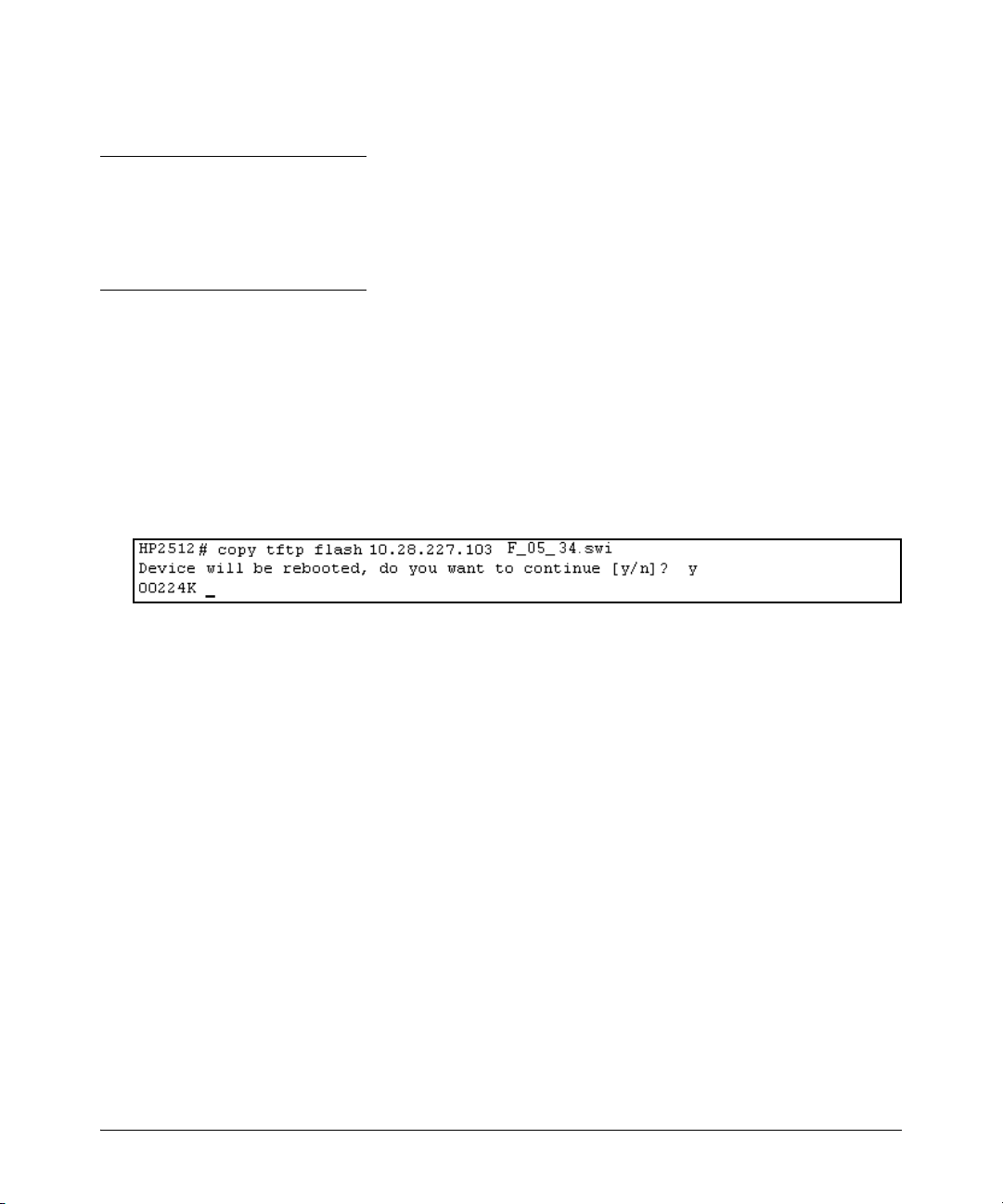
Syntax:copy tftp flash <ip-address> <remote-os-file>
For example, to download a software file named F_05_34.swi from a TFTP server with the IP address
of 10.28.227.103:
1. Execute the copy command as shown below:
2. When the switch finishes downloading the software file from the server, it displays this progress
message:
Validating and Writing System Software to FLASH . . .
3. After the switch reboots, it displays the CLI or Main Menu, depending on the Logon Default setting
last configured in the menu’s Switch Setup screen.
2
Page 14

Software Management
Xmodem Download From a PC or Unix Workstation
This procedure assumes that:
■ The switch is connected via the Console RS-232 port on a PC operating as a terminal. (Refer to
the Installation Guide you received with the switch for information on connecting a PC as a
terminal and running the switch console interface.)
■ The switch software is stored on a disk drive in the PC.
■ The terminal emulator you are using includes the Xmodem binary transfer feature. (For example,
in the Windows NT terminal emulator, you would use the Send File option in the T
menu.)
Syntax:copy xmodem flash <unix | pc>
For example, to download a software file from a PC:
1. To reduce the download time, you may want to increase the baud rate in your terminal emulator
and in the switch to a value such as 57600 bits per second. (The baud rate must be the same in
both devices.) For example, to change the baud rate in the switch to 57600, execute this
command:
HP2512(config)# console baud-rate 57600
(If you use this option, be sure to set your terminal emulator to the same baud rate.)
ransfer dropdown
2. Execute the following command in the CLI:
3. Execute the terminal emulator commands to begin the Xmodem transfer.
The download can take several minutes, depending on the baud rate used in the transfer.
When the download finishes, the switch automatically reboots itself and begins running the new
software version.
4. To confirm that the software downloaded correctly:
HP2512> show system
Check the Firmware revision line.
5. If you increased the baud rate on the switch (step 1), use the same command to return it to its
previous setting. (HP recommends a baud rate of 9600 bits per second for most applications.)
(Remember to return your terminal emulator to the same baud rate as the switch.)
3
Page 15

Software Management
Saving Configurations While Using the CLI
The switch operates with two configuration files:
■ Running-Config File: Exists in volatile memory and controls switch operation. Rebooting
the switch erases the current running-config file and replaces it with an exact copy of the
current startup-config file. To save a configuration change, you must save the running
configuration to the startup-config file.
■ Startup-Config File: Exists in flash (non-volatile) memory and preserves the most recently-
saved configuration as the "permanent" configuration. When the switch reboots for any
reason, an exact copy of the current startup-config file becomes the new running-config file
in volatile memory.
When you use the CLI to make a configuration change, the switch places the change in the runningconfig file. If you want to preserve the change across reboots, you must save the change to the startupconfig file. Otherwise, the next time the switch reboots, the change will be lost. There are two ways
to save configuration changes while using the CLI:
■ Execute the write memory command from the Manager, Global, or Context configuration
level.
■ When exiting from the CLI to the Main Menu, press [Y] (for Yes) when you see the save
configuration prompt:
Do you want to save current configuration [y/n] ?
4
Page 16

Software Management
ProCurve Switch, Routing Switch, and Router Software Keys
Software
Letter
CY Switch 8100fl Series (8108fl and 8116fl)
ProCurve Networking Products
C 1600M, 2400M, 2424M, 4000M, and 8000M
E Switch 5300xl Series (5304xl, 5308xl, 5348xl, and 5372xl)
F Switch 2500 Series (2512 and 2524), Switch 2312, and Switch 2324
G Switch 4100gl Series (4104gl, 4108gl, and 4148gl)
H Switch 2600 Series, Switch 2600-PWR Series: H.07.81 and earlier, or H.08.55 and greater,
Switch 2600-8-PWR requires H.08.80 or greater.
Switch 6108: H.07.xx and earlier
I Switch 2800 Series (2824 and 2848)
J Secure Router 7000dl Series (7102dl and 7203dl)
K Switch 3500yl Series (3500yl-24G-PWR and 3500yl-48G-PWR), Switch 6200yl-24G, 5400zl Series (5406zl,
5406zl-48G, 5412zl, 5412zl-96G) and Switch 8212zl.
L Switch 4200vl Series (4204vl, 4208vl, 4202vl-72, and 4202vl-48G)
M Switch 3400cl Series (3400-24G and 3400-48G): M.08.51 though M.08.97, or M.10.01 and greater;
Series 6400cl (6400cl-6XG CX4, and 6410cl-6XG X2 ): M.08.51 though M.08.95, or M.08.99 to M.08.100 and
greater.
N Switch 2810 Series (2810-24G and 2810-48G)
PA/PB Switch 1800 Series (Switch 1800-8G – PA.xx; Switch 1800-24G – PB.xx)
Q Switch 2510 Series (2510-24)
R Switch 2610 Series (2610-24, 2610-24/12PWR, 2610-24-PWR, 2610-48 and 2610-48-PWR)
T Switch 2900 Series (2900-24G, and 2900-48G)
U Switch 2510-48
VA/VB Switch 1700 Series (Switch 1700-8 - VA and 1700-24 - VB)
WA ProCurve Access Point 530
WS ProCurve Wireless Edge Services xl Module and the ProCurve Redundant Wireless Services xl Module
WT ProCurve Wireless Edge Services zl Module and the ProCurve Redundant Wireless Services zl Module
Y Switch 2510G Series (2510G-24 and 2510G-48)
numeric Switch 9408sl, Switch 9300 Series (9304M, 9308M, and 9315M), Switch 6208M-SX and Switch 6308M-SX
(Uses software version number only; no alphabetic prefix. For example 07.6.04.)
5
Page 17

Enhancements in Release F.05.05 through F.05.70
Enhancements in Release F.05.61 through F.05.70
Enhancements in Release F.05.05 through F.05.70
Enhancements in Release F.05.61 through F.05.70
No new enhancements, software fixes only.
Enhancements in Release F.05.05 through F.05.60
Enhancement Summary Page
LLDP Implements the industry standard Link Layer Discovery Protocol (LLDP) on your
Disable Auto MDIX A new global command, "no auto-mdix", that disables Auto-MDIX for all ports
New Console Option A new console option removes terminal escape sequences, which allows
Clarification of Time Zone The method of configuring the Time Zone for TimeP or SNTP configuration has
Syslog (Syslogd)capability Adds the ability to direct Event Log messaging to an external file as an aid in
Isolated Port Groups Originally added in release F.04.08 to provide an alternative to VLANs, this
Port-Based Access Control
(802.1X) with Open VLAN Mode
IGMP Version 3 Support The switch now supports operation with IGMPv3 traffic. 71
switch, as an alternative to the Cisco Discovery Protocol (CDP). The LLDP
provides a standards-based method for enabling switches to advertise themselves to adjacent devices.
that are in auto-negotiation mode.
scripts to better interact with the Command Line Interface.
been updated.
debugging network-level problems. Complies with RFC 3164.
feature now offers two new isolation groups: group1 and group2.
Originally added in release F.04.08 to provide access control through a RADIUS
server, this feature now includes Open VLAN Mode. This gives you a means for
allowing a client computer without 802.1X supplicant software to temporarily
join an unauthorized-client VLAN and proceed with initialization services, such
as acquiring IP addressing, 802.1X supplicant software, and other optional
services you may want to provide.
7
14
15
15
16
20
29
6
Page 18

Enhancements in Release F.05.05 through F.05.70
Enhancements in Release F.05.05 through F.05.60
Implementation of LLDP
For network device discovery solutions, software version F.05.50 implements a limited version of
the industry standard Link Layer Discovery Protocol (LLDP) on your switch, as an alternative to the
Cisco Discovery Protocol (CDP).
The Link Layer Discovery Protocol (LLDP) provides a standards-based method for enabling switches
to advertise themselves to adjacent devices and to learn about adjacent LLDP devices. The Series
2500 switches using F.05.50 - F.05.59 will transmit LLDP advertisements, but do not support discovery
of connected LLDP neighbor devices.
With F.05.60 or later, Series 2500 switches can receive LLDP packets, thereby supporting discovery
of connected LLDP neighbor devices and providing enhanced operation with ProCurve Manager
utilities.
Note
Selected LLDP information (such as system name, port description, port type, chassis type) received
by a Series 2500 switch from a remote neighbor is not viewable.
LLDP Terminology
Adjacent Device: Refer to “Neighbor or Neighbor Device”.
Advertisement: See LLDPDU.
Active Port: A port linked to another active device (regardless of whether STP is blocking the link).
LLDP: Link Layer Discovery Protocol. ProCurve switches are compatible with IEEE 802.1AB-2005.
LLDP-Aware: A device that has LLDP in its operating code, regardless of whether LLDP is enabled
or disabled.
LLDP Device: A switch, server, router, or other device running LLDP.
LLDP Neighbor: An LLDP device that is either directly connected to another LLDP device or
connected to that device by another, non-LLDP Layer 2 device (such as a hub) Note that an 802.1Dcompliant switch does not forward LLDP data packets even if it is not LLDP-aware.
LLDPDU (LLDP Data Unit): LLDP data packets are transmitted on active links and include multiple
TLVs containing global and per-port switch information. In this guide, LLDPDUs are termed
“advertisements” or “packets”.
7
Page 19

Enhancements in Release F.05.05 through F.05.70
Enhancements in Release F.05.05 through F.05.60
MIB (Management Information Base): An internal database the switch maintains for configuration
and performance information.
Neighbor: See “LLDP Neighbor”.
Non_LLDP Device: A device that is not capable of LLDP operation.
TLV (Type-Length-Value): A data unit that includes a data type field, a data unit length field (in
bytes), and a field containing the actual data the unit is designed to carry (as an alphanumeric string,
a bitmap, or a subgroup of information). Some TLVs include subelements that occur as separate data
points in displays of information maintained by the switch for LLDP advertisements. (That is, some
TLVs include multiple data points or subelements.)
General LLDP Operation
An LLDP packet contains data about the transmitting switch and port. The switch advertises itself
to adjacent (neighbor) devices by transmitting LLDP data packets out all ports on which outbound
LLDP is enabled. (LLDP is a one-way protocol and does not include any acknowledgement
mechanism.)
Packet Boundaries in a Network Topology
■ Where multiple LLDP devices are directly connected, an outbound LLDP packet travels only to
the next LLDP device. An LLDP-capable device does not forward LLDP packets to any other
devices, regardless of whether they are LLDP-capable.
■ An intervening hub or repeater forwards the LLDP packets it receives in the same manner as any
other multicast packets it receives. Thus, two LLDP switches joined by a hub or repeater handle
LLDP traffic in the same way that they would if directly connected.
■ Any intervening 802.1D device, or Layer-3 device that is either LLDP-unaware or has disabled
LLDP operation, drops the packet.
LLDP Configuration Options
Enable or Disable LLDP on the Switch. In the default configuration, LLDP is globally enabled
on the switch. To prevent transmission/reception of LLDP traffic, you can disable LLDP operation.
Tra n sm i t M od e . With LLDP enabled, the switch periodically (30 second intervals) transmits an
LLDP advertisement (packet) out each active port enabled for outbound LLDP transmissions. You
can enable or disable LLDP packet transmissions on a per-port basis. If a port is disabled, the switch
does not use the port to inform LLDP neighbors of its presence.
The following table lists the information the switch includes in the per-port, outbound LLDP packets
it generates. In the default configuration, all outbound LLDP packets include this information in the
TLVs transmitted to neighbor devices.
8
Page 20

Enhancements in Release F.05.05 through F.05.70
Enhancements in Release F.05.05 through F.05.60
Table 1. Viewable Data Available for LLDP Advertisements
Data Type Description
Chassis ID Uses base MAC address of the switch.
Port Id Uses port number of the physical port.
System Description Includes switch model name and running software version, and ROM version.
System Name Uses the switch’s assigned name.
Remote Management Address
Type
Address
Port Description Uses the physical port identifier.
System capabilities supported Identifies the switch’s primary capabilities (bridge, router).
System cpabilities enabled Identifies the primary switch functions that are enabled, such as routing.
NOTES:
• The Packet Time-to-Live (TTL) value is not viewable, but is included in LLDP data packets.
• TTL of an advertised frame is 120 seconds.
• The data used for LLDP advertisement is captured internally by the switch. For more on these data types, refer to
the IEEE 802.1AB-2005 Standard.
Shows the network address type.
The switch IP address. This can be either an address selected by a default process,
or an address configured for inclusion in advertisements.
(Address configuration not supported on 2500).
Note
Selected LLDP information (such as system name, port description, port type, chassis type) received
by a Series 2500 switch from a remote neighbor is not viewable.
LLDP Standards Compatibility
The LLDP features for the Series 2500 switches are compatible with the following LLDP-related
standards:
■ IEEE 802.1AB-2005 for LLDP packets send. LLDP reception, standard LLDP MIBs, and LLDP
state machine is not supported
■ RFC 2922 (PTOPO, or Physical Topology MIB)
■ RFC 2737 (Entity MIB)
■ RFC 2863 (Interfaces MIB)
9
Page 21

Enhancements in Release F.05.05 through F.05.70
Enhancements in Release F.05.05 through F.05.60
LLDP Operating Rules
Port Trunking. LLDP manages trunked ports individually. That is, trunked ports are configured
individually for LLDP operation, in the same manner as non-trunked ports. Also, LLDP sends separate
advertisements on each port in a trunk, and not on a per-trunk basis.
IP Address Advertisements. In the default operation, if a port belongs to only one static VLAN,
then the port advertises the lowest-order IP address configured on that VLAN. If a port belongs to
multiple VLANs, then the port advertises the lowest-order IP address configured on the VLAN with
the lowest VID. If the qualifying VLAN does not have an IP address, the port advertises the base MAC
address of the device as its IP address. For example, if the port is a member of the default VLAN
(VID = 1), and there is an IP address configured for the default VLAN, then the port advertises this
IP address. In the default operation, the IP address that LLDP uses can be an address acquired by
DHCP or Bootp.
Spanning-Tree Blocking. Spanning tree does not prevent LLDP packet transmission on STPblocked links.
802.1X Blocking. Ports blocked by 802.1X operation do not allow transmission of LLDP packets.
10
Page 22

Enhancements in Release F.05.05 through F.05.70
Enhancements in Release F.05.05 through F.05.60
LLDP Operation and Commands
In the default configuration, LLDP is enabled to transmit on all active ports. The LLDP configuration
includes global settings that apply to all active ports on the switch, and per-port settings that affect
only the operation of the specified ports.
Viewing the Current LLDP Configuration
Use the show lldp config command to display the switch’s general LLDP configuration status,
including some per-port information affecting advertisement traffic.
Syntax show lldp config
Displays the LLDP global configuration and LLDP port status.
For example, show lldp config produces the following display when the switch is in the default LLDP
configuration:
HP ProCurve Switch 2524# show lldp config
LLDP Global Configuation
LLDP Enabled [Yes]: Yes
LLDP Transmit Interval: 30(Not Configurable)
LLDP Port Configuration
Port | LLDP
---- + --- 1 | enabled
2 | enabled
3 | enabled
4 | enabled
5 | enabled
6 | enabled
7 | enabled
8 | enabled
.
.
26 | enabled
HP ProCurve Switch 2524#
Figure 1. Example of Viewing the General LLDP Configuration
11
Page 23

Enhancements in Release F.05.05 through F.05.70
Enhancements in Release F.05.05 through F.05.60
Viewing LLDP-detected Devices
Note
Selected LLDP information (such as system name, port description, port type, chassis type) received
by a Series 2500 switch from a remote neighbor is not viewable.
With version F.05.60, LLDP advertisements from remote neighbor devices can be received. Use the
show lldp info remote-device command to display information received from LLDP remote devices.
Syntax show lldp info remote-device [ < local port > ]
Displays LLDP Remote Device Information.
<local port>: If the local port number connected to the remote
device is specified, additional details of the remote device are
displayed.
For example, show lldp info remote-device produces the following display when LLDP is enabled and
a device is detected:
HP ProCurve Switch 2524# show lldp info remote-device
LLDP Remote Device Information
Local Port | Chassis Id Port Id Port Descr SysName
---------- + ------------------ ------- ---------- -------- 1 | 0030c1-7fec40 5
HP ProCurve Switch 2524#
Figure 2. Example of Viewing the LLDP Remote Device List
12
Page 24

Enhancements in Release F.05.05 through F.05.70
Enhancements in Release F.05.05 through F.05.60
Additional information from the remote device can be displayed by specifying the local port number
in the command. For example, show lldp info remote-device 1 produces the following display:
HP ProCurve Switch 2524# show lldp info remote-device 1
LLDP Remote Device Information Detail
LocalPort : 1
ChassisType :
ChassisId : 0030c1-7fec40
PortType :
PortId : 5
SysName :
SysDescr : HP J4812A ProCurve Switch 2512, revision F.05.60, ROM F.0...
PortDescr :
System Capabilities Supported : Bridge
System Capabilities Enabled : Bridge
Remote Managment Address
Type : ipv4
Address : 169.254.123.128
HP ProCurve Switch 2524#
Figure 3. Example of Viewing the LLDP Remote Device Information Details
Enabling or Disabling LLDP Operation on the Switch.
The lldp run command configures the LLDP operation that applies to all ports in the switch. Enabling
LLDP operation (the default) causes the switch to use active, LLDP-enabled ports to transmit/receive
LLDP packets.
Syntax [ no ] lldp run
Enables or disables LLDP operation on the switch. The no form of the
command, regardless of individual LLDP port configurations, prevents the
switch from transmitting/receiving LLDP advertisements. The switch
preserves the current LLDP configuration when LLDP is disabled.
(Default: Enabled)
For example, to disable LLDP on the switch, use the command:
ProCurve(config)# no lldp run
13
Page 25

Enhancements in Release F.05.05 through F.05.70
Enhancements in Release F.05.05 through F.05.60
Configuring Per-Port LLDP Transmit/Receive
This command controls LLDP transmit/receive traffic on active ports.
Syntax lldp admin-status < port-list > < enable | disable >
enable: With LLDP enabled on the switch in the default LLDP
configuration, each port is configured to transmit/receive
LLDP packets. This option lets you enable the specified port(s)
to transmit/receive LLDP packets. (For versions F.05.59 and
earlier, inbound LLDP packets from neighbor devices are not
supported on 2500 series switches.)
disable: Disable LLDP packet transmit/receive on the specified
port(s).
For example, to disable LLDP on port 1, use the command:
ProCurve(config)# lldp admin-status 1 disable
Disable Auto-MDIX
The Auto-MDIX feature allows a user to connect 10/100 switch ports to either MDI or MDI-X devices
using a straight-through cable. In some situations it is desirable to disable this feature. Beginning
with release F.05.24 there is a global command, no auto-mdix, that disables Auto-MDIX for all ports
that are in auto-negotiation mode.
Restrictions:
■ works only on copper ports
■ requires the port be brought down to change to/from Auto-MDIX
■ applies globally to all ports
■ with Auto-MDIX disabled, ports set to auto-negotiate operate in MDI-X mode
14
Page 26

Enhancements in Release F.05.05 through F.05.70
Enhancements in Release F.05.05 through F.05.60
New Console Option
Starting with Release F.05.23, a new console option removes terminal escape sequences, which allows
scripts to better interact with the Command Line Interface. The command console local-terminal none
changes the current terminal session to "raw" mode. To return to the default VT-100 mode, use the
command
console local-terminal vt100.
This option does not require a reboot to take effect, and does not persist across reboots. It affects
only the console session in which the command is executed.
Clarification of Time Zone Issue
Enhancement Summary Page
Syslog (Syslogd)capability Adds the ability to direct Event Log messaging to an external file as an aid in
Isolated Port Groups Originally added in release F.04.08 to provide an alternative to VLANs, this
Port-Based Access Control
(802.1X) with Open VLAN Mode
IGMP Version 3 Support The switch now supports operation with IGMPv3 traffic. 71
debugging network-level problems. Complies with RFC 3164.
feature now offers two new isolation groups: group1 and group2.
Originally added in release F.04.08 to provide access control through a RADIUS
server, this feature now includes Open VLAN Mode. This gives you a means for
allowing a client computer without 802.1X supplicant software to temporarily
join an unauthorized-client VLAN and proceed with initialization services, such
as acquiring IP addressing, 802.1X supplicant software, and other optional
services you may want to provide.
16
20
29
Starting with the F.05.xx version of the switch software, the method of configuring the Time Zone
for TimeP or SNTP configuration has been updated. Previous switch software, for all ProCurve
switches, used positive time offset values for time zones that are West of GMT and negative values
for time zones that are East of GMT. The standards indicate that time zones West of GMT should be
designated by negative offset values, and time zones East of GMT by positive values. Software version
F. 0 5. xx updates this configuration method, but if you use the same values for indicating time zones
as you did for previous ProCurve switches, the time will be set incorrectly on your ProCurve Switches
2512 and 2524. For example, for previous ProCurve switches, the US Pacific time zone was configured
by entering +480. With software version F.05.xx, the US Pacific time zone must now be configured by
entering -480.
15
Page 27
Enhancements in Release F.05.05 through F.05.70
Enhancements in Release F.05.05 through F.05.60
Syslog Overview
The switch’s Event Log records switch-level progress, status, and warning messages. The SystemLogging (Syslog) feature provides a means for recording these messages on a remote server. The
Syslog feature complies with RFC 3168. UNIX users know this capability as ’Syslogd’. Using Syslog
you can send Event Log messages from multiple switches to a central location to help investigate
and identify network-level problems. (Refer to Figure 4 below.)
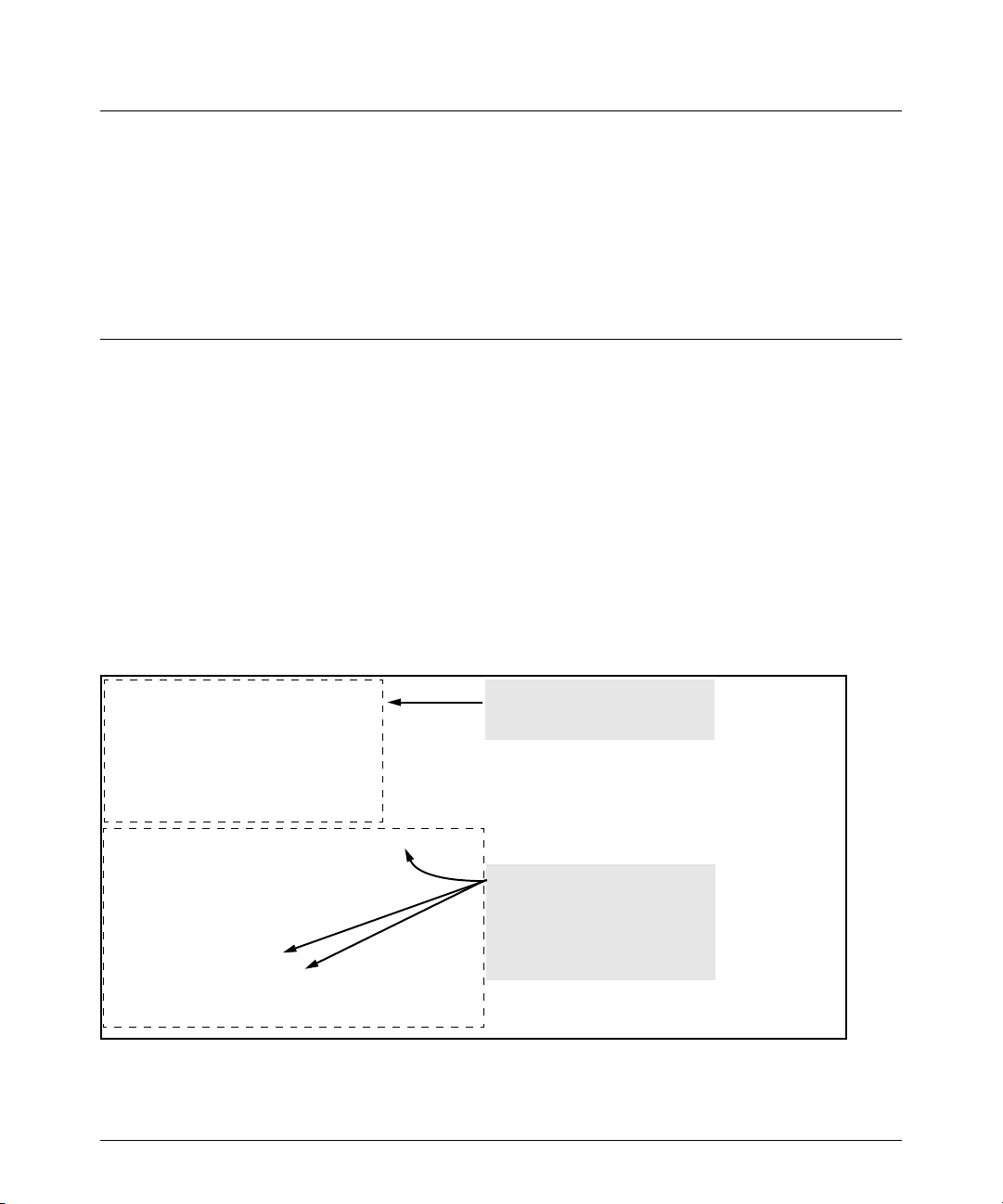
You can configure the switch to send Event Log messages to up to six Syslog servers. Messages are
sent to the User log facility (default) on the configured server(s) or to another log facility that you
specify.
Two switches sending Event Log
messages to the same facility on a
single Syslog server.
Figure 4. A Syslog server collecting Event Log Messages from Multiple Switches
Syslog Operation
Syslog is a client-server logging tool that allows a client switch to send event notification messages
to a networked device operating with Syslog server software. Messages sent to a Syslog server can
be stored to a file for later debugging analysis. Use of Syslog requires that you set up a Syslog server
application on a networked host accessible to the switch. (Refer to the documentation for the Syslog
server application you select.)
Syntax: [no] logging < syslog-ip-addr >
Enables or disables Syslog messaging to the specified IP
address. You can configure up to six addresses.
no logging removes all currently configured Syslog logging
destinations from the switch.
16
Page 28

Enhancements in Release F.05.05 through F.05.70
Enhancements in Release F.05.05 through F.05.60
no logging < syslog-ip-address > removes only the specified Syslog
logging destination from the switch.
17
Page 29

Syntax: [no] logging facility < facility-name >
The logging facility specifies the destination subsystem the
Syslog server(s) must use. (All Syslog servers configured on the
switch must use the same subsystem.) HP recommends the
default (user) subsystem unless your application specifically
requires another subsystem. Options include:
user (the default) — Random user-level messages
kern — Kernel messages
mail — Mail system
daemon — System daemons
auth — Security/Authorization messages
syslog — Messages generated internally by Syslog
lpr — Line-Printer subsystem
news — Netnews subsystem
uucp — uucp subsystem
cron — cron/at subsystem
sys9 — cron/at subsystem
sys10 - sys14 — Reserved for system use
local10 - local17 — Reserved for system use
Enhancements in Release F.05.05 through F.05.70
Enhancements in Release F.05.05 through F.05.60
Note
As of March 2004, the logging facility < facility-name > option also is available on these switch models:
■ Switch Series 5300XL (software release E.08.xx or greater)
■ Switch Series 4100GL (software release G.07.50 or greater)
■ Switch Series 2800
■ Switch Series 2600 and the Switch 6108 (software release H.07.30 or greater)
For the latest feature information on ProCurve switches, visit the ProCurve Web site and check the
latest release notes for the switch products you use.
18
Page 30
Enhancements in Release F.05.05 through F.05.70
Enhancements in Release F.05.05 through F.05.60
Viewing the Syslog Configuration
Syntax: show debug
This command displays the currently configured Syslog logging destination(s) and logging facility. For examples of show
debug output, refer to figure 5 on page 19.
Configuring Syslog Logging
1. If you want to use a Syslog server for recording Event Log messages:
a. Use this command to configure the Syslog server IP address and enable Syslog logging:
ProCurve(config)# logging < ip-addr >
Using this command when there are no Syslog server IP addresses already configured
enables messaging to a Syslog server.
b. Use the command in step “a” to configure any additional Syslog servers you want to use, up
to a total of six.
Example: Suppose there are no Syslog servers configured on the switch (the default). Configuring
one Syslog server enables Event Log messages to be sent to that server. (Refer to Figure 5 below.)
ProCurve(config)# show debug
Debug Logging
Destination: None
Enabled debug types:
None are enabled.
ProCurve(config)# logging 10.250.125.69
ProCurve(config)# show debug
Debug Logging
Destination:
Logging --
10.250.125.69
Facility = user
Enabled debug types:
event
Displays the default debug
configuration. (There are no
Syslog server IP addresses
When the logging command
configures a Syslog IP address, the
switch automatically enables
sending Event Log messages to the
Syslog address and the user
facility on the Syslog server.
Figure 5. Example of Configuring Syslog Operation
19
Page 31

Enhancements in Release F.05.05 through F.05.70
Enhancements in Release F.05.05 through F.05.60
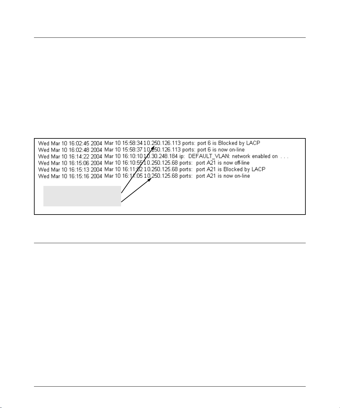
See Figure 6 below for an example of adding an additional Syslog server.
Continuing the example begun in
figure 2, this command adds a
second Syslog server.
Lists the IP addresses of the Syslog
servers configured on the switch.
Messages must be sent to the
same facility on each Syslog
Figure 6. Configuring multiple Syslog Servers
Operating Notes for Syslog
■ Rebooting the switch or pressing the Reset button resets the Debug Configuration. Any Syslog
server IP addresses written in the startup-config file are saved across a reboot and logging
remains enabled. Any Syslog server IP addresses existing only in the running-config file are lost
if the switch reboots. (Use the write memory command to save configuration changes to the
Startup-config file.)
■ Up to six Syslog servers may be configured to receive Event Log messages. All switches must
use the same Syslog facility.
Isolated Port Groups (Enhanced)
Isolated Port-Group Commands
[no] port-isolation page 25
port-isolation [ethernet] < port-list > mode
< uplink | public | group1 | group2 | private | local >
show port-isolation page 25
page 25
20
Page 32

Enhancements in Release F.05.05 through F.05.70
Enhancements in Release F.05.05 through F.05.60
The Isolated Port Groups feature originally included in release F.04.08 has been enhanced in release
F. 0 5. xx with the inclusion of two new port isolation groups (group1 and group2).
Isolated port groups provide an alternative to VLANs for isolating end nodes on your network, while
simplifying network administration. This feature enables you to isolate traffic to and from specific
end-node devices, which enhances security and also helps in such areas as selectively preventing
internet use. There are, however, some limitations, as outlined in the "Rules of Operation", described
later in this section.
Caution
The Isolated Port Groups feature is intended for rare situations where using VLANs is not possible.
This feature can interfere with other switch features, and improper configuration will result in
unexpected connectivity problems. Refer to “Operating Rules for Port Isolation” on page 23.
The Isolated Port Groups feature operates within the context of the individual switch. It does not
restrict free communication on the designated uplink port(s) to other devices on the network. A node
connected to any type of port (group1, group2, private, etc.) on one Series 2500 switch can
communicate with a node connected to any type of port (group1, group2, private, etc.) on another
Series 2500 switch if the two switches are connected through their uplink ports.
Options for Isolated Port Groups
Using Isolated Port Groups, you can control traffic between ports on the switch by assigning an
appropriate port type to each port. The options include:
■ Uplink (the default)
■ Public
■ Group1
When you configure isolated port groups on a switch, traffic is allowed to move between the switch
ports as described in table 2 and shown in figure 7, both below.
■ Group2
■ Private
■ Local
21
Page 33

Enhancements in Release F.05.05 through F.05.70
Enhancements in Release F.05.05 through F.05.60
Table 2. Communication Allowed Between Port-Isolation Types within a Switch
Port Type: Permits Traffic To and From
This Port Type?
Uplink
Ports
Public
Ports
Group1
Ports
Group2
Ports
Local
Public
Yes Yes No No Yes No Typical switch ports: For intra-switch operation, allows communi-
Ports
Uplink
Yes Yes Yes Yes No Yes Allows communication between uplink ports and end nodes on
Ports
Group1
Yes No Yes No No No Allows communication among end nodes on other group-1 ports,
Ports
Group2
Yes No No Yes No No Allows communication among end nodes on other Group2 ports,
Ports
Local
No Yes No No Yes No Allows communication among end nodes on local and public ports.
Ports
Private
Yes No No No No No Allows communication only between end nodes and uplink ports.
Ports
Notes
Ports
Private
Ports
cation among end nodes on public and local ports, and between end
nodes on public ports and the uplink port(s).
public and private ports. Uplink ports are intended for connecting
the switch to the network core. When you enable port isolation on
the switch, Uplink is the default port-isolation mode setting for
individual ports.
and between end nodes on Group1 ports and the Uplink port(s).
and between end nodes on Group2 ports and the Uplink port(s).
Group1
Uplink
Local
Public
Uplink
Group2
Group1
Public
Private
Public
Uplink
Local
Public
Group1
Local
Figure 7. Communication Allowed Between Port-Isolation Types within a Switch
Group2
Group2
Private Uplink
Uplink
22
Page 34

Enhancements in Release F.05.05 through F.05.70
Enhancements in Release F.05.05 through F.05.60
Operating Rules for Port Isolation
■ Port Isolation is intended only for networks that do not use VLAN tagging. (The switch must
be in the default VLAN configuration before you configure port-isolation.)
■ Multiple VLANs are not allowed on the switch. If multiple VLANs exist on the switch, delete
them and return the ports to the original default configuration as untagged members of VLAN
1. (VLAN configuration changes are not supported if port-isolation is running on the switch.)
■ Trunking is supported only on Uplink ports between switches. Remove any other port
trunking from the switch.
■ LACP is allowed only on the Uplink ports. For security, LACP (active or passive) must be
disabled on all other ports on the switch. To disable LACP active or passive on the switch’s
ports, use this command syntax:
no int e < port-numbers > lacp
■ GVRP must be disabled (the default).
■ IGMP operates only in non-data-driven mode, and works only on uplink ports. The switch
floods multicast IP traffic arriving at non-uplink ports.
■ A Series 2500 switch with port-isolation enabled cannot export its port-isolation configura-
tion. However, a Series 2500 configuration file on a server can include port-isolation
commands.
■ The Isolated Port Groups feature operates within the context of the individual switch. It does
not restrict free communication on the designated uplink port(s) to other devices on the
network. A node connected to any non-local port (group1, group2, private, etc.) on one Series
2500 switch can communicate with a node connected to any non-local port (group1, group2,
private, etc.) on another Series 2500 switch if the two switches are connected through their
uplink ports.
■ Enabling port isolation and configuring individual ports to specific, non-default modes are
separate steps. You must first enable port isolation. When you do so, all ports are configured
in the (default) Uplink mode.
23
Page 35

Enhancements in Release F.05.05 through F.05.70
Enhancements in Release F.05.05 through F.05.60
Configuring Port Isolation on the Switch
Steps for Configuring Port Isolation
1. Remove all non-default VLANs from the switch and ensure that all ports are untagged members
of the default VLAN (VID = 1).
2. Identify the devices you will connect to the switch’s ports.
3. Configure all equipment you plan to attach to the switch (such as servers and other switches)
to eliminate VLAN tagging on ports connected to the Series 2500 switch(es) on which you are
using Port Isolation.
4. Determine the mode assignment you want for each port on the switch. (When you enable portisolation, the switch configures all ports to the default Uplink mode.)
5. Remove port trunks you have configured from ports that you plan to configure in public, local,
or private mode.
6. Disable LACP on all ports that you plan to configure in public, local, or private mode. To do so,
use this command: no interface e < port-list > lacp.
7. Enable port isolation on the switch.
8. Configure the non-default port-isolation mode for each port that you do not want to operate in
the Uplink mode.
9. Connect the switch ports to the other devices in your port-isolation plan.
10. Test the operation of all ports you are using for links to the other devices.
11. When you are satisfied that your port-isolation configuration is working properly, execute write
mem to store the configuration in the startup-config file.
24
Page 36

Enhancements in Release F.05.05 through F.05.70
Enhancements in Release F.05.05 through F.05.60
Configuring and Viewing Port-Isolation
Syntax: [ no ] port-isolation
Without any port-list or mode parameters, enables port isolation on the switch
and sets all ports to the Uplink mode. The no version disables port isolation and
also causes all individual ports to be set to the (default) Uplink mode the next time
you enable port isolation.
[ ethernet ] < port-list > mode < uplink | public | group1 | group2 | private | local >
Specifies the ports you want to configure to a particular port-isolation mode
(uplink—the default— public, group1, group2, private, local).
show port-isolation
Lists the switch’s port-isolation status and, if enabled, the port-isolation mode and
which ports, if any, are in a port trunk.
show running-config
Lists the switch’s running configuration, including port-isolation settings.
show config
Lists the switch’s startup configuration, including port-isolation settings.
Note
The no port-isolation command erases all port-isolation mode settings from memory. This means that
whenever you disable, then re-enable port isolation, all ports on the switch will be set to the (default)
Uplink mode.
25
Page 37

Enhancements in Release F.05.05 through F.05.70
Enhancements in Release F.05.05 through F.05.60
For example, suppose that the switch is in its default configuration (no multiple VLANs; GVRP
disabled, all ports untagged members of the default VLAN—VID = 1) with two optional gigabit
transceivers installed, and you wanted to use the switch ports as shown in table table 3, “Port Isolation
Plan”:
Table 3. Port Isolation Plan
Port Use Allowed Traffic Blocked
1 - 3 Local ports only for isolated work-
group access. (No network or
internet access.)
1
4 - 8 Group1 ports for workgroup and
network/internet access
2
9 Private port to a secure end node; no
traffic exchange with non-uplink
ports on the switch.
• Traffic between any ports in the
local set (ports 1, 2, and 3)
• Traffic between any port in the
local set and any port in the public
set (ports 10, 11, or 12)
• Traffic between any ports in the
group1 set (ports 4 through 8)
• Traffic between any port in group1
and the uplink ports
Traffic between port 9 (private) and
the gigabit trunk used as an uplink
(ports 13 and 14).
3
10 - 12 Public ports for typical end-node
access.
4
13 -14 Gigabit uplink to the network. • Traffic between any ports in the
5
• Traffic between any ports in the
public set (ports 10, 11, and 12)
• Traffic between any port in the
public set and any port in the local
or uplink port sets
uplink set (ports 13 and 14)
• Traffic between any port in the
uplink set and any port in the
public, private, or group1 sets
Traffic between any port in
the local set and any port in
the private, group1, or
uplink port sets
Traffic between any port in
the group1 set (ports 4 - 8)
and any public, private, or
local ports
Traffic between port 9 and
any port in the local, public,
or group1 port sets, or any
other private port on the
switch
Traffic between any port in
the public set (ports 10 - 12)
and any port in the group1
or private port sets
Traffic between any port in
the uplink set and any port
in the local set
26
Page 38
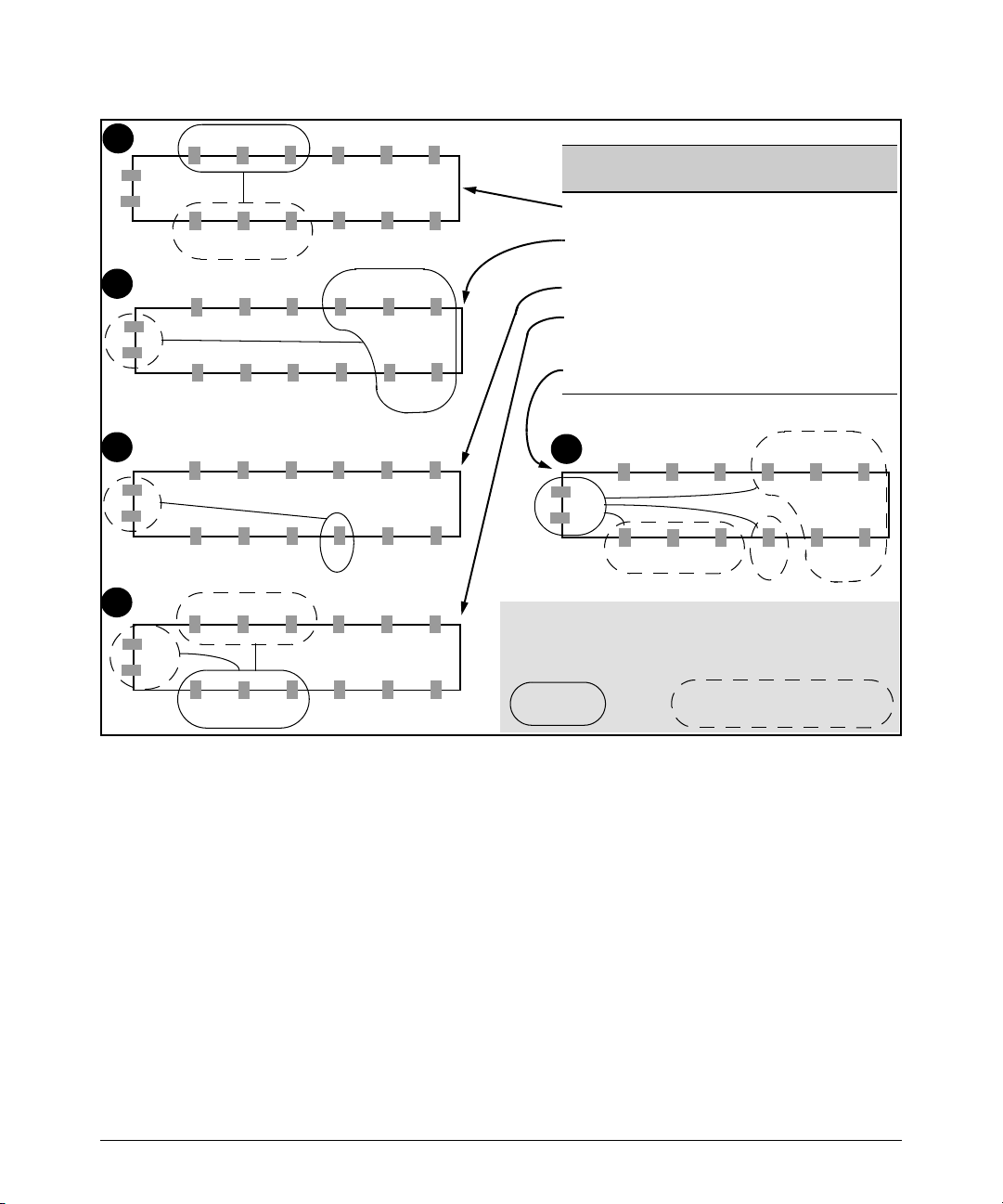
Enhancements in Release F.05.05 through F.05.70
Enhancements in Release F.05.05 through F.05.60
1
2
14
13
3
14
13
4
1 2 3 4 5 6
14
13
12 11 10 9 8 7
1 2 3 4 5 6
12 11 10 9 8 7
1 2 3 4 5 6
12 11 10 9 8 7
1 2 3 4 5 6
14
13
12 11 10 9 8 7
Port Mode Internal Traffic Destinations
1 - 3 Local Each Other and Ports 10 - 12
4 - 8 Group1 Each Other and Ports 13 and 14
9 Private Gigabit Trunk (ports 13 & 14)
10 - 12 Public Each Other, Ports 1 - 3, and the
13 - 14 Uplink Ports 4 - 8 (group1), 9 (private), 10
5
This figure illustrates the port isolation example described in table
3 on page 26. Each switch view belongs to the same configuration
and illustrates the indicated port set and the permitted
communication for that set.
Configured
Port Set
1 2 3 4 5 6
14
13
12 11 10 9 8 7
Allowed by Port Isolation Mode
(uplinks)
Uplink Ports.
-12 (public)
Other Port Set(s) Available to a
Configured Port Set
Figure 8. Example of Isolating Ports on a Series 2500 Switch
Assuming a switch in the factory-default configuration, you would configure the port isolation plan
in figure 8 as follows:
27
Page 39

Enhancements in Release F.05.05 through F.05.70
Enhancements in Release F.05.05 through F.05.60
Remember to disable LACP on ports that will be configured
for Public, Group1, Group2, Private, or Local mode. (Refer
to “Operating Rules for Port Isolation” on page 23.)
When you enter the command to enable port
isolation, the switch displays a caution and
prompts you to indicate how to proceed. Type
[Y] to continue with enabling port isolation; [N]
to leave port isolation disabled. See the Caution
on page 21.
Uplink mode is the default setting for all ports when you enable port-isolation.
Since these two ports were not explicitly configured, above, they remain in
the Uplink mode (and do not need to be explicitly configured as uplinks).
Figure 9. Example of Port-Isolation Configuration
Messages Related to Port-Isolation Operation
Message Meaning
Port Isolation is
disabled. It must be
enabled first.
In the switch’s factory-default state or after you execute no port-isolation, you must enable
port isolation (by executing port-isolation alone) before entering commands for changing
the mode on one or more ports.
28
Page 40

Enhancements in Release F.05.05 through F.05.70
Enhancements in Release F.05.05 through F.05.60
Troubleshooting Port-Isolation Operation
Symptom Possible Cause
Connectivity
problems.
• A port may be configured as a tagged member of a VLAN, or multiple VLANs may be configured
on the switch. Ensure that all ports are untagged members of VLAN 1 (the default VLAN) and that
no other VLANs are configured on the switch.
• Illegal port trunking. Port Isolation does not allow trunks on Private ports, or more than one PortIsolation type in a trunk. Also, Port Isolation allows an LACP trunk only on Uplink ports.
• A port on a device connected to the switch may be configured as a tagged member of a VLAN.
• GVRP may be enabled on the switch.
See “Operating Rules for Port Isolation” on page 23 and “Steps for Configuring Port Isolation” on
page 24.
Configuring Port-Based Access Control (802.1X)
Overview
Feature Default Menu CLI Web
Configuring Switch Ports as 802.1X Authenticators Disabled n/a page 38 n/a
Configuring 802.1X Open VLAN Mode Disabled n/a page 44 n/a
Configuring Switch Ports to Operate as 802.1X Supplicants Disabled n/a page 57 n/a
Displaying 802.1X Configuration, Statistics, and Counters n/a n/a page 61 n/a
How 802.1X Affects VLAN Operation n/a n/a page 67 n/a
RADIUS Authentication and Accounting Refer to “Configuring RADIUS Authentication and
Accounting” on page -102
Why Use Port-Based Access Control?
Local Area Networks are often deployed in a way that allows unauthorized clients to attach to
network devices, or allows unauthorized users to get access to unattended clients on a network. Also,
the use of DHCP services and zero configuration make access to networking services easily available.
This exposes the network to unauthorized use and malicious attacks. While access to the network
should be made easy, uncontrolled and unauthorized access is usually not desirable. 802.1X provides
access control along with the ability to control user profiles from a central RADIUS server while
allowing users access from multiple points within the network.
29
Page 41

Enhancements in Release F.05.05 through F.05.70
Enhancements in Release F.05.05 through F.05.60
General Features
802.1X on the Series 2500 switches includes the following:
■ Switch operation as both an authenticator (for supplicants having a point-to-point connec-
tion to the switch) and as a supplicant for point-to-point connections to other 802.1X-aware
switches.
• Authentication of 802.1X clients using a RADIUS server and either the EAP or CHAP
protocol.
• Provision for enabling clients that do not have 802.1 supplicant software to use the
switch as a path for downloading the software and initiating the authentication process
(802.1X Open VLAN mode).
• Supplicant implementation using CHAP authentication and independent username and
password configuration on each port.
■ Prevention of traffic flow in either direction on unauthorized ports.
■ Local authentication of 802.1X clients using the switch’s local username and password (as
an alternative to RADIUS authentication).
■ Temporary on-demand change of a port’s VLAN membership status to support a current
client’s session. (This does not include ports that are members of a trunk.)
■ Session accounting with a RADIUS server, including the accounting update interval.
■ Use of Show commands to display session counters.
■ With port-security enabled for port-access control, limit a port to one 802.1X client session
at a given time.
Authenticating Users. Port-Based Access Control (802.1X) provides switch-level security that
allows LAN access only to users who enter the authorized RADIUS username and password on
802.1X-capable clients (supplicants). This simplifies security management by allowing you to control
access from a master database in a single server (although you can use up to three RADIUS servers
to provide backups in case access to the primary server fails). It also means a user can enter the same
username and password pair for authentication, regardless of which switch is the access point into
the LAN. Note that you can also configure 802.1X for authentication through the switch’s local
username and password instead of a RADIUS server, but doing so increases the administrative
burden, decentralizes username/password administration, and reduces security by limiting authentication to one Operator/Manager password set for all users.
Providing a Path for Downloading 802.1X Supplicant Software. For clients that do not have
the necessary 802.1X supplicant software, there is also the option to configure the 802.1X Open VLAN
mode. This mode allows you to assign such clients to an isolated VLAN through which you can provide
the necessary supplicant software these clients need to begin the authentication process. (Refer to
“802.1X Open VLAN Mode” on page -44.)
30
Page 42

Enhancements in Release F.05.05 through F.05.70
Enhancements in Release F.05.05 through F.05.60
Authenticating One Switch to Another. 802.1X authentication also enables the switch to operate
as a supplicant when connected to a port on another switch running 802.1X authentication.
Switch Running 802.1X and
Operating as an Authenticator
802.1X-Aware Client
(Supplicant)
Switch Running 802.1X and
LAN Core
Connected as a Supplicant
RADIUS Server
Figure 10. Example of an 802.1X Application
Accounting . The Series 2500 switches also provide RADIUS Network accounting for 802.1X access.
Refer to “Configuring RADIUS Authentication and Accounting” on page -102.
How 802.1X Operates
Authenticator Operation
This operation provides security on a direct, point-to-point link between a single client and the switch,
where both devices are 802.1X-aware. (If you expect desirable clients that do not have the necessary
802.1X supplicant software, you can provide a path for downloading such software by using the
802.1X Open VLAN mode—refer to “802.1X Open VLAN Mode” on page 44.) For example, suppose
that you have configured a port on the switch for 802.1X authentication operation. If you then connect
an 802.1X-aware client (supplicant) to the port and attempt to log on:
1. When the switch detects the client on the port, it blocks access to the LAN from that port.
2. The switch responds with an identity request.
3. The client responds with a user name that uniquely defines this request for the client.
4. The switch responds in one of the following ways:
• If 802.1X (port-access) on the switch is configured for RADIUS authentication, the
switch then forwards the request to a RADIUS server.
i. The server responds with an access challenge which the switch forwards to the client.
ii. The client then provides identifying credentials (such as a user certificate), which the
switch forwards to the RADIUS server.
iii. The RADIUS server then checks the credentials provided by the client.
31
Page 43

Enhancements in Release F.05.05 through F.05.70
Enhancements in Release F.05.05 through F.05.60
iv. If the client is successfully authenticated and authorized to connect to the network,
then the server notifies the switch to allow access to the client. Otherwise, access is
denied and the port remains blocked.
• If 802.1X (port-access) on the switch is configured for local authentication, then:
i. The switch compares the client’s credentials with the username and password config-
ured in the switch (Operator or Manager level).
ii. If the client is successfully authenticated and authorized to connect to the network,
then the switch allows access to the client. Otherwise, access is denied and the port
remains blocked.
Switch-Port Supplicant Operation
This operation provides security on links between 802.1X-aware switches. For example, suppose that
you want to connect two switches, where:
■ Switch “A” has port 1 configured for 802.1X supplicant operation.
■ You want to connect port 1 on switch “A” to port 5 on switch “B”.
Switch “B”
Port 5
Port 1
Switch “A”
Port 1 Configured as an
802.1X Supplicant
LAN Core
RADIUS Server
Figure 11. Example of Supplicant Operation
1. When port 1 on switch “A” is first connected to a port on switch “B”, or if the ports are already
connected and either switch reboots, port 1 begins sending start packets to port 5 on switch “B”.
• If, after the supplicant port sends the configured number of start packets, it does not
receive a response, it assumes that switch “B” is not 802.1X-aware, and transitions to
the authenticated state. If switch “B” is operating properly and is not 802.1X-aware, then
the link should begin functioning normally, but without 802.1X security.
• If, after sending one or more start packets, port 1 receives a request packet from port 5,
then switch “B” is operating as an 802.1X authenticator. The supplicant port then sends
a response/ID packet. Switch “B” forwards this request to a RADIUS server.
32
Page 44

Enhancements in Release F.05.05 through F.05.70
Enhancements in Release F.05.05 through F.05.60
2. The RADIUS server then responds with an MD5 access challenge that switch “B” forwards to
port 1 on switch “A”.
3. Port 1 replies with an MD5 hash response based on its username and password or other unique
credentials. Switch “B” forwards this response to the RADIUS server.
4. The RADIUS server then analyzes the response and sends either a “success” or “failure” packet
back through switch “B” to port 1.
• A “success” response unblocks port 5 to normal traffic from port 1.
• A “failure” response continues the block on port 5 and causes port 1 to wait for the “held-
time” period before trying again to achieve authentication through port 5.
Note
You can configure a switch port to operate as both a supplicant and an authenticator at the same time.
Terminology
802.1X-Aware: Refers to a device that is running either 802.1X authenticator software or 802.1X
client software and is capable of interacting with other devices on the basis of the IEEE 802.1X
standard.
Authorized-Client VLAN: Like the Unauthorized-Client VLAN, this is a conventional, static VLAN
previously configured on the switch by the System Administrator. The intent in using this VLAN
is to provide authenticated clients with network services that are not available on either the port’s
statically configured VLAN memberships or any VLAN memberships that may be assigned during
the RADIUS authentication process. While an 802.1X port is a member of this VLAN, the port is
untagged. When the client connection terminates, the port drops its membership in this VLAN.
Authentication Server: The entity providing an authentication service to the switch when the
switch is configured to operate as an authenticator. In the case of a Series 2500 switch running
802.1X, this is a RADIUS server (unless local authentication is used, in which case the switch
performs this function using its own username and password for authenticating a supplicant).
Authenticator: In ProCurve switch applications, a device such as a Series 2500 switch that requires
a supplicant to provide the proper credentials (username and password) before being allowed
access to the network.
CHAP (MD5): Challenge Handshake Authentication Protocol.
Client: In this application, an end-node device such as a management station, workstation, or mobile
PC linked to the switch through a point-to-point LAN link.
33
Page 45

Enhancements in Release F.05.05 through F.05.70
Enhancements in Release F.05.05 through F.05.60
EAP (Extensible Authentication Protocol): EAP enables network access that supports multiple
authentication methods.
EAPOL: Extensible Authentication Protocol Over LAN, as defined in the 802.1X standard.
Friendly Client: A client that does not pose a security risk if given access to the switch and your
network.
MD5: An algorithm for calculating a unique digital signature over a stream of bytes. It is used by
CHAP to perform authentication without revealing the shared secret (password).
PVID (Port VID): This is the VLAN ID for the untagged VLAN to which an 802.1X port belongs.
Static VLAN: A VLAN that has been configured as “permanent” on the switch by using the CLI vlan
< vid > command or the Menu interface.
Supplicant: The entity that must provide the proper credentials to the switch before receiving access
to the network. This is usually an end-user workstation, but it can be a switch, router, or another
device seeking network services.
Tagged VLAN Membership: T h i s t y p e o f V LA N me mb er sh ip al lo ws a p or t t o b e a me mb er of m u lt i p le
VLANs simultaneously. If a client connected to the port has an software that supports 802.1q
VLAN tagging, then the client can access VLANs for which the port is a tagged member. If the
client does not support VLAN tagging, then it can access only a VLAN for which the port is an
untagged member. (A port can be an untagged member of only one VLAN at a time.) 802.1X Open
VLAN mode does not affect a port’s tagged VLAN access unless the port is statically configured
as a member of a VLAN that is also configured as the Unauthorized-Client or Authorized-Client
VLAN. See also “Untagged VLAN Membership”.
Unauthorized-Client VLAN: A conventional, static VLAN previously configured on the switch by
the System Administrator. It is used to provide access to a client prior to authentication. It should
be set up to allow an unauthenticated client to access only the initialization services necessary
to establish an authenticated connection, plus any other desirable services whose use by an
unauthenticated client poses no security threat to your network. (Note that an unauthenticated
client has access to all network resources that have membership in the VLAN you designate as
the Unauthorized-Client VLAN.) A port configured to use a given Unauthorized-Client VLAN does
not have to be statically configured as a member of that VLAN as long as at least one other port
on the switch is statically configured as a tagged or untagged member of the same UnauthorizedClient VLAN.
Untagged VLAN Membership: A port can be an untagged member of only one VLAN. (In the factory-
default configuration, all ports on the switch are untagged members of the default VLAN.) An
untagged VLAN membership is required for a client that does not support 802.1q VLAN tagging.
A port can simultaneously have one untagged VLAN membership and multiple tagged VLAN
memberships. Depending on how you configure 802.1X Open VLAN mode for a port, a statically
configured, untagged VLAN membership may become unavailable while there is a client session
on the port. See also “Tagged VLAN Membership”.
34
Page 46

Enhancements in Release F.05.05 through F.05.70
Enhancements in Release F.05.05 through F.05.60
General Operating Rules and Notes
■ When a port on the switch is configured as either an authenticator or supplicant and is
connected to another device, rebooting the switch causes a re-authentication of the link.
■ When a port on the switch is configured as an authenticator, it will block access to a client
that either does not provide the proper authentication credentials or is not 802.1X-aware.
(You can use the optional 802.1X Open VLAN mode to open a path for downloading 802.1X
supplicant software to a client, which enables the client to initiate the authentication
procedure. Refer to “802.1X Open VLAN Mode” on page -44.)
■ If a port on switch “A” is configured as an 802.1X supplicant and is connected to a port on
another switch, “B”, that is not 802.1X-aware, access to switch “B” will occur without 802.1X
security protection.
■ You can configure a port as both an 802.1X authenticator and an 802.1X supplicant.
■ If a port on switch “A” is configured as both an 802.1X authenticator and supplicant and is
connected to a port on another switch, “B”, that is not 802.1X-aware, access to switch “B”
will occur without 802.1X security protection, but switch “B” will not be allowed access to
switch “A”. This means that traffic on this link between the two switches will flow from “A”
to “B”, but not the reverse.
■ If a client already has access to a switch port when you configure the port for 802.1X
authenticator operation, the port will block the client from further network access until it
can be authenticated.
■ On a port configured for 802.1X with RADIUS authentication, if the RADIUS server specifies
a VLAN for the supplicant and the port is a trunk member, the port will be blocked. If the
port is later removed from the trunk, the port will try to authenticate the supplicant. If
authentication is successful, the port becomes unblocked. Similarly, if the supplicant is
authenticated and later the port becomes a trunk member, the port will be blocked. If the
port is then removed from the trunk, it tries to re-authenticate the supplicant. If successful,
the port becomes unblocked.
■ To help maintain security, 802.1X and LACP cannot both be enabled on the same port. If you
try to configure 802.1X on a port already configured for LACP (or the reverse) you will see
a message similar to the following:
Error configuring port X: LACP and 802.1X cannot be run together.
Note on 802.1X and LACP
To help maintain security, the switch does not allow 802.1X and LACP to both be enabled at the same
time on the same port. Refer to “802.1X Operating Messages” on page -70.
35
Page 47

Enhancements in Release F.05.05 through F.05.70
Enhancements in Release F.05.05 through F.05.60
General Setup Procedure for Port-Based Access Control (802.1X)
Do These Steps Before You Configure 802.1X Operation
1. Configure a local username and password on the switch for both the Operator (login) and
Manager (enable) access levels. (While this may or may not be required for your 802.1X
configuration, HP recommends that you use a local username and password pair at least until
your other security measures are in place.)
2. Determine which ports on the switch you want to operate as authenticators and/or supplicants,
and disable LACP on these ports. (See the “Note on 802.1X and LACP” on page -35.)
3. Determine whether to use the optional 802.1X Open VLAN mode for clients that are not 802.1Xaware; that is, for clients that are not running 802.1X supplicant software. (This will require you
to provide downloadable software that the client can use to enable an authentication session.)
For more on this topic, refer to “802.1X Open VLAN Mode” on page -44.
4. For each port you want to operate as a supplicant, determine a username and password pair.
You can either use the same pair for each port or use unique pairs for individual ports or
subgroups of ports. (This can also be the same local username/password pair that you assign
to the switch.)
5. Unless you are using only the switch’s local username and password for 802.1X authentication,
configure at least one RADIUS server to authenticate access requests coming through the ports
on the switch from external supplicants (including switch ports operating as 802.1X supplicants). You can use up to three RADIUS servers for authentication; one primary and two
backups. Refer to the documentation provided with your RADIUS application.
Overview: Configuring 802.1X Authentication on the Switch
This section outlines the steps for configuring 802.1X on the switch. For detailed information on each
step, refer to “Configuring RADIUS Authentication and Accounting” on page -102 or “Configuring
Switch Ports To Operate As Supplicants for 802.1X Connections to Other Switches” on page -57.
1. Enable 802.1X authentication on the individual ports you want to serve as authenticators. On
the ports you will use as authenticators, either accept the default 802.1X settings or change
them, as necessary. Note that, by default, the port-control parameter is set to auto for all ports
on the switch. This requires a client to support 802.1X authentication and to provide valid
credentials to get network access. Refer to page -39.
2. If you want to provide a path for clients without 802.1X supplicant software to download the
software so that they can initiate an authentication session, enable the 802.1X Open VLAN mode
on the ports you want to support this feature. Refer to page 44.
36
Page 48

Enhancements in Release F.05.05 through F.05.70
Enhancements in Release F.05.05 through F.05.60
3. Configure the 802.1X authentication type. Options include:
• Local Operator username and password (the default). This option allows a client to use
the switch’s local username and password as valid 802.1X credentials for network
access.
• EAP RADIUS: This option requires your RADIUS server application to support EAP
authentication for 802.1X.
• CHAP (MD5) RADIUS: This option requires your RADIUS server application to support
CHAP (MD5) authentication.
See page -42.
4. If you select either eap-radius or chap-radius for step 3, use the radius host command to configure
up to three RADIUS server IP address(es) on the switch. See page -43.
5. Enable 802.1X authentication on the switch. See page 39.
6. Test both the authorized and unauthorized access to your system to ensure that the 802.1X
authentication works properly on the ports you have configured for port-access.
Note
If you want to implement the optional port security feature (step 7) on the switch, you should first
ensure that the ports you have configured as 802.1X authenticators operate as expected.
7. If you are using Port Security on the switch, configure the switch to allow only 802.1X access
on ports configured for 802.1X operation, and (if desired) the action to take if an unauthorized
device attempts access through an 802.1X port. See page 55.
8. If you want a port on the switch to operate as a supplicant in a connection with a port operating
as an 802.1X authenticator on another device, then configure the supplicant operation. (Refer
to “Configuring Switch Ports To Operate As Supplicants for 802.1X Connections to Other
Switches” on page -57.)
37
Page 49

Enhancements in Release F.05.05 through F.05.70
Enhancements in Release F.05.05 through F.05.60
Configuring Switch Ports as 802.1X Authenticators
802.1X Authentication Commands Page
[no] aaa port-access authenticator < [ethernet] < port-list >39
[control | quiet-period | tx-period | supplicant-timeout |
server-timeout | max-requests | reauth-period | auth-vid |
unauth-vid | initialize | reauthenticate | clear-statistics]
aaa authentication port-access 42
< local | eap-radius | chap-radius >
[no] aaa port-access authenticator active 38
[no] port-security [ethernet] < port-list > learn-mode port-access 55
802.1X Open VLAN Mode Commands 44
802.1X Supplicant Commands 57
802.1X-Related Show Commands 61
RADIUS server configuration 43
39
38
Page 50

Enhancements in Release F.05.05 through F.05.70
Enhancements in Release F.05.05 through F.05.60
1. Enable 802.1X Authentication on Selected Ports
This task configures the individual ports you want to operate as 802.1X authenticators for point-topoint links to 802.1X-aware clients or switches. (Actual 802.1X operation does not commence until
you perform step 5 on page 37 to activate 802.1X authentication on the switch.)
Note
When you enable 802.1X authentication on a port, the switch automatically disables LACP on that port.
However, if the port is already operating in an LACP trunk, you must remove the port from the trunk before
you can configure it for 802.1X authentication.
Syntax: aaa port-access authenticator < port-list >
Enables specified ports to operate as 802.1X authenticators
with current per- port authenticator configuration. To activate configured 802.1X operation, you must enable 802.1X
authentication. Refer to “5. Enable 802.1X Authentication
on the switch” on page 37.
[control < authorized | auto | unauthorized >]
Controls authentication mode on the specified port:
authorized: Also termed Force Authorized. Grants access to
any device connected to the port. In this case, the device does
not have to provide 802.1X credentials or support 802.1X
authentication. (However, you can still configure console,
Telnet, or SSH security on the port.)
auto (the default): The device connected to the port must
support 802.1X authentication and provide valid credentials in order to get network access. (You have the option of
using the Open VLAN mode to provide a path for clients
without 802.1X supplicant software to download this software and begin the authentication process. Refer to “802.1X
Open VLAN Mode” on page -44.)
unauthorized: Also termed Force Unauthorized. Do not grant
access to the network, regardless of whether the device
provides the correct credentials and has 802.1X support. In
this state, the port blocks access to any connected device.
39
Page 51

Enhancements in Release F.05.05 through F.05.70
Enhancements in Release F.05.05 through F.05.60
Syntax: aaa port-access authenticator < port-list > (Syntax Continued)
[quiet-period < 0 - 65535 >]
Sets the period during which the port does not try to acquire
a supplicant. The period begins after the last attempt authorized by the max-requests parameter fails (next page).
(Default: 60 seconds)
[tx-period < 0 - 65535 >]
Sets the period the port waits to retransmit the next EAPOL
PDU during an authentication session. (Default: 30
seconds)
[supplicant-timeout < 1 - 300 >]
Sets the period of time the switch waits for a supplicant
response to an EAP re quest. If the supplicant does not
respond within the configured time frame, the session times
out. (Default: 30 seconds)
[server-timeout < 1 - 300 >]
Sets the period of time the switch waits for a server response
to an authentication request. If there is no response within
the configured time frame, the switch assumes that the
authentication attempt has timed out. Depending on the
current max-requests setting, the switch will either send a
new request to the server or end the authentication session.
(Default: 30 seconds)
[max-requests < 1 - 10 >]
Sets the number of authentication attempts that must timeout before authentication fails and the authentication
session ends. If you are using the Local authentication
option, or are using RADIUS authentication with only one
host server, the switch will not start another session until a
client tries a new access attempt. If you are using RADIUS
authentication with two or three host servers, the switch will
open a session with each server, in turn, until authentication occurs or there are no more servers to try. During the
quiet-period (previous page), if any, you cannot reconfigure
this parameter. (Default: 2)
40
Page 52

Enhancements in Release F.05.05 through F.05.70
Enhancements in Release F.05.05 through F.05.60
Syntax: aaa port-access authenticator < port-list > (Syntax Continued)
[reauth-period < 1 - 9999999 >]
Sets the period of time after which clients connected must be
re-authenticated. When the timeout is set to 0 the reauthentication is disabled (Default: 0 second)
[unauth-vid < vlan-id >]
Configures an existing static VLAN to be the UnauthorizedClient VLAN. This enables you to provide a path for clients
without supplicant software to download the software and
begin an authentication session. Refer to “802.1X Open
VLAN Mode” on page -44.
[auth-vid < vid >
Configures an existing, static VLAN to be the AuthorizedClient VLAN. Refer to “802.1X Open VLAN Mode” on page 44.
[initialize]
On the specified ports, blocks inbound and outbound traffic
and restarts the 802.1X authentication process. This
happens only on ports configured with control auto and
actively operating as 802.1X authenticators. Note: If a
specified port is configured with control authorized and port-
security, and the port has learned an authorized address, the
port will remove this address and learn a new one from the
first packet it receives.
[reauthenticate]
Forces reauthentication (unless the authenticator is in
'HELD' state).
[clear-statistics]
Clears authenticator statistics counters.
41
Page 53

Enhancements in Release F.05.05 through F.05.70
Enhancements in Release F.05.05 through F.05.60
3. Configure the 802.1X Authentication Method
This task specifies how the switch will authenticate the credentials provided by a supplicant
connected to a switch port configured as an 802.1X authenticator.
Syntax: aaa authentication port-access < local | eap-radius | chap-radius >
Determines the type of RADIUS authentication to use.
local Use the switch’s local username and password for
supplicant authentication.
eap-radius Use EAP-RADIUS authentication. (Refer to the
documentation for your RADIUS server.)
chap-radius Use CHAP-RADIUS (MD-5) authentication.
(Refer to the documentation for your RADIUS server application.)
For example, to enable the switch to perform 802.1X authentication using one or more EAP-capable
RADIUS servers:
Figure 12. Example of 802.1X (Port-Access) Authentication
Configuration command for
EAP-RADIUS
authentication.
802.1X (Port-Access)
configured for EAPRADIUS authentication.
42
Page 54

Enhancements in Release F.05.05 through F.05.70
Enhancements in Release F.05.05 through F.05.60
4. Enter the RADIUS Host IP Address(es)
If you selected either eap-radius or chap-radius for the authentication method, configure the switch
to use 1 to 3 RADIUS servers for authentication. The following syntax shows the basic commands.
For coverage of all commands related to RADIUS server configuration, refer to “Configuring RADIUS
Authentication and Accounting” on page -102.
Syntax: radius host < ip-address >
Adds a server to the RADIUS configuration.
[key < server-specific key-string >]
Optional. Specifies an encryption key for use during
authentication (or accounting) sessions with the specified server. This key must match the key used on the
RADIUS server. Use this option only if the specified
server requires a different key than configured for the
global encryption key.
radius-server key < global key-string >
Specifies the global encryption key the switch uses for
sessions with servers for which the switch does not have
a server-specific key. This key is optional if all RADIUS
server addresses configured in the switch include a
server- specific encryption key.
5. Enable 802.1X Authentication on the Switch
After configuring 802.1X authentication as described in the preceding four sections, activate it with
this command:
Syntax: aaa port-access authenticator active
Activates 802.1X port-access on ports you have configured
as authenticators.
43
Page 55

Enhancements in Release F.05.05 through F.05.70
Enhancements in Release F.05.05 through F.05.60
802.1X Open VLAN Mode
802.1X Authentication Commands page 38
802.1X Supplicant Commands page 58
802.1X Open VLAN Mode Commands
[no] aaa port-access authenticator [e] < port-list > page 53
[auth-vid < vlan-id >]
[unauth-vid < vlan-id >]
802.1X-Related Show Commands page 61
RADIUS server configuration pages 43
This section describes how to use the 802.1X Open VLAN mode to configure unauthorized-client and
authorized-client VLANs on ports configured as 802.1X authenticators.
Introduction
Configuring the 802.1X Open VLAN mode on a port changes how the port responds when it detects
a new client. In earlier releases, a “friendly” client computer not running 802.1X supplicant software
could not be authenticated on a port protected by 802.1X access security. As a result, the port would
become blocked and the client could not access the network. This prevented the client from:
■ Acquiring IP addressing from a DHCP server
■ Downloading the 802.1X supplicant software necessary for an authentication session
The 802.1X Open VLAN mode solves this problem by temporarily suspending the port’s static,
untagged VLAN membership and placing the port in a designated Unauthorized-Client VLAN. In this
state the client can proceed with initialization services, such as acquiring IP addressing and 802.1X
software, and starting the authentication process. Following authentication, the port drops its
temporary (untagged) membership in the Unauthorized-Client VLAN and joins (or rejoins) one of the
following as an untagged member:
■ 1st Priority: The port joins a VLAN to which it has been assigned by a RADIUS server during
authentication.
■ 2nd Priority: If RADIUS authentication does not include assigning a VLAN to the port, then
the switch assigns the port to the VLAN entered in the port’s 802.1X configuration as an
Authorized-Client VLAN, if configured.
44
Page 56

Enhancements in Release F.05.05 through F.05.70
Enhancements in Release F.05.05 through F.05.60
■ 3rd Priority: If the port does not have an Authorized-Client VLAN configured, but does have
a static, untagged VLAN membership in its configuration, then the switch assigns the port to
this VLAN.
If the port is not configured for any of the above, then it must be a tagged member of at least one
VLAN. In this case, if the client is capable of operating in a tagged VLAN, then it can access that VLAN.
Otherwise, the connection will fail.
Caution
If a port is a tagged member of a statically configured VLAN, 802.1X Open VLAN mode does not
prevent unauthenticated client access to such VLANs if the client is capable of operating in a tagged
VLAN environment. To avoid possible security breaches, HP recommends that you not allow a tagged
VLAN membership on a port configured for 802.1X Open VLAN mode unless you use the tagged VLAN
as the Unauthorized-Client VLAN.
Use Models for 802.1X Open VLAN Modes
You can apply the 802.1X Open VLAN mode in more than one way. Depending on your use, you will
need to create one or two static VLANs on the switch for exclusive use by per-port 802.1X Open VLAN
mode authentication:
■ Unauthorized-Client VLAN: Configure this VLAN when unauthenticated, friendly clients
will need access to some services before being authenticated.
■ Authorized-Client VLAN: Configure this VLAN for authenticated clients when the port is
not statically configured as an untagged member of a VLAN you want clients to use, or when
the port is statically configured as an untagged member of a VLAN you do not want clients
to use. (A port can be configured as untagged on only one VLAN. When an Authorized-Client
VLAN is configured, it will always be untagged and will block the port from using a statically
configured, untagged membership in another VLAN.)
45
Page 57

Enhancements in Release F.05.05 through F.05.70
Enhancements in Release F.05.05 through F.05.60
Table 4. 802.1X Open VLAN Mode Options
802.1X Per-Port Configuration Port Response
No Open VLAN mode: The port automatically blocks a client that cannot initiate an authen-
tication session.
Open VLAN mode with both of the following configured:
Unauthorized-Client VLAN • When the port detects a client, it automatically becomes an
untagged member of this VLAN. If you previously configured the
port as a static, tagged member of the VLAN, membership
temporarily changes to untagged while the client remains
unauthenticated.
• If the port already has a statically configured, untagged
membership in another VLAN, then the port temporarily closes
access to this other VLAN while in the Unauthorized-Client VLAN.
• To limit security risks, the network services and access available
on the Unauthorized-Client VLAN should include only what a client
needs to enable an authentication session. If the port is statically
configured as a tagged member of any other VLANs, access to
these VLANs remains open, even though the client may not be
authenticated. Refer to the Caution on page 45.
Authorized-Client VLAN • After the client is authenticated, the port drops membership in the
Unauthorized-Client VLAN and becomes an untagged member of
this VLAN.
Note: If RADIUS authentication assigns a VLAN, the port
temporarily becomes a member of the RADIUS-assigned VLAN
—instead of the Authorized-Client VLAN—while the client is
connected.
• If the port is statically configured as a tagged member of a VLAN,
and this VLAN is used as the Authorized-Client VLAN, then the port
temporarily becomes an untagged member of this VLAN when the
client becomes authenticated. When the client disconnects, the
port returns to tagged membership in this VLAN.
• If the port is statically configured as a tagged member of a VLAN
that is not used by 802.1X Open VLAN mode, an unauthenticated
client capable of operating in tagged VLANs has access to this
VLAN. Refer to the Caution on page 45.
46
Page 58

Enhancements in Release F.05.05 through F.05.70
Enhancements in Release F.05.05 through F.05.60
802.1X Per-Port Configuration Port Response
Open VLAN Mode with Only an Unauthorized-Client VLAN Configured:
• When the port detects a client, it automatically becomes an
untagged member of this VLAN. To limit security risks, the network
services and access available on this VLAN should include only
what a client needs to enable an authentication session. If the port
is statically configured as an untagged member of another VLAN,
the switch temporarily removes the port from membership in this
other VLAN while membership in the Unauthorized-Client VLAN
exists.
• After the client is authenticated, and if the port is statically
configured as an untagged member of another VLAN, the port’s
access to this other VLAN is restored.
• If the port is statically configured as a tagged member of a VLAN
that is not used by 802.1X Open VLAN mode, an unauthenticated
client capable of operating in tagged VLANs can access this
VLAN. Refer to the Caution on page 45.
Note: If RADIUS authentication assigns a VLAN to the port, this
assignment overrides any statically configured, untagged VLAN
membership on the port (while the client is connected).
Open VLAN Mode with Only an Authorized-Client VLAN Configured:
• Port automatically blocks a client that cannot initiate an
authentication session.
• If the client successfully completes an authentication session, the
port becomes an untagged member of this VLAN.
• If the port is statically configured as a tagged member of any other
VLANs, an authenticated client capable of operating in a tagged
VLAN environment can access these VLANs.
Note: If RADIUS authentication assigns a VLAN, the port temporarily
becomes a member of the RADIUS-assigned VLAN —instead of the
Authorized-Client VLAN—while the client is connected.
47
Page 59

Enhancements in Release F.05.05 through F.05.70
Enhancements in Release F.05.05 through F.05.60
Operating Rules for Authorized-Client and Unauthorized-Client VLANs
Condition Rule
Static VLANs used as AuthorizedClient or Unauthorized-Client VLANs
VLAN Assignment Received from a
RADIUS Server
Temporary VLAN Membership During
a Client Session
Effect of Unauthorized-Client VLAN
session on untagged port VLAN
membership
Effect of Authorized-Client VLAN
session on untagged port VLAN
membership.
These must be configured on the switch before you configure an
802.1X authenticator port to use them. (Use the vlan < vlan-id >
command or the VLAN Menu screen in the Menu interface.)
If the RADIUS server specifies a VLAN for an authenticated supplicant
connected to an 802.1X authenticator port, this VLAN assignment
overrides any Authorized-Client VLAN assignment configured on the
authenticator port. This is because both VLANs are untagged, and the
switch allows only one untagged VLAN membership per-port. For
example, suppose you configured port 4 to place authenticated supplicants in VLAN 20. If a RADIUS server authenticates supplicant “A”
and assigns this supplicant to VLAN 50, then the port can access VLAN
50 for the duration of the client session. When the client disconnects
from the port, then the port drops these assignments and uses only
the VLAN memberships for which it is statically configured.
• Port membership in a VLAN assigned to operate as the
Unauthorized-Client VLAN is temporary, and ends when the client
receives authentication or the client disconnects from the port,
whichever is first.
• Port membership in a VLAN assigned to operate as the AuthorizedClient VLAN is also temporary, and ends when the client
disconnects from the port.If a VLAN assignment from a RADIUS
server is used instead, the same rule applies.
• When an unauthenticated client connects to a port that is already
configured with a static, untagged VLAN, the switch temporarily
moves the port to the Unauthorized-Client VLAN (also untagged).
(While the Unauthorized-Client VLAN is in use, the port does not
access the static, untagged VLAN.)
• When the client either becomes authenticated or disconnects, the
port leaves the Unauthorized-Client VLAN and reacquires its
untagged membership in the statically configured VLAN.
• When a client becomes authenticated on a port that is already
configured with a static, untagged VLAN, the switch temporarily
moves the port to the Authorized-Client VLAN (also untagged).
While the Authorized-Client VLAN is in use, the port does not have
access to the statically configured, untagged VLAN.
• When the authenticated client disconnects, the switch removes the
port from the Authorized-Client VLAN and moves it back to the
untagged membership in the statically configured VLAN.
48
Page 60

Enhancements in Release F.05.05 through F.05.70
Enhancements in Release F.05.05 through F.05.60
Condition Rule
Multiple Authenticator Ports Using
the Same Unauthorized-Client and
Authorized-Client VLANs
You can use the same static VLAN as the Unauthorized-Client VLAN
for all 802.1X authenticator ports configured on the switch. Similarly,
you can use the same static VLAN as the Authorized-Client VLAN for
all 802.1X authenticator ports configured on the switch.
Caution: Do not use the same static VLAN for both the unauthorized
and the Authorized-Client VLAN. Using one VLAN for both creates a
security risk by defeating the isolation of unauthenticated clients.
Effect of Failed Client Authentication
Attempt
When there is an Unauthorized-Client VLAN configured on an 802.1X
authenticator port, an unauthorized client connected to the port has
access only to the network resources belonging to the UnauthorizedClient VLAN. (There can be an exception to this rule if the port is also
a tagged member of a statically configured VLAN. Refer to the Caution
on page 45.) This access continues until the client disconnects from
the port. (If there is no Unauthorized-Client VLAN configured on the
authenticator port, the port simply blocks access for any unauthorized
client that cannot be authenticated.)
Sources for an IP Address Configuration for a Client Connected to a Port
A client can either acquire an IP address from a DHCP server or have
a preconfigured, manual IP address before connecting to the switch.
Configured for 802.x Open VLAN
Mode
802.1X Supplicant Software for a
Client Connected to aPort Configured
for 802.1X Open VLAN Mode
A friendly client, without 802.1X supplicant software, connecting to an
authenticator port must be able to download this software from the
Unauthorized-Client VLAN before authentication can begin.
Note:
If you use the same VLAN as the Unauthorized-Client VLAN for all authenticator ports, unauthenticated clients on different ports can communicate with each other. However, in this case, you can
improve security between authenticator ports by using the switch’s Source-Port filter feature. For
example, if you are using ports 1 and 2 as authenticator ports on the same Unauthorized-Client VLAN,
you can configure a Source-Port filter on 1 to drop all packets from 2 and the reverse.
49
Page 61

Enhancements in Release F.05.05 through F.05.70
Enhancements in Release F.05.05 through F.05.60
Setting Up and Configuring 802.1X Open VLAN Mode
Preparation. This section assumes use of both the Unauthorized-Client and Authorized-Client
VLANs. Refer to Table 4 on page 46 for other options.
Before you configure the 802.1X Open VLAN mode on a port:
■ Statically configure an “Unauthorized-Client VLAN” in the switch. The only ports that should
belong to this VLAN are ports offering services and access you want available to unauthenticated clients. (802.1X authenticator ports do not have to be members of this VLAN.)
Caution
Do not allow any port memberships or network services on this VLAN that would pose a security
risk if exposed to an unauthorized client.
■ Statically configure an Authorized-Client VLAN in the switch. The only ports that should
belong to this VLAN are ports offering services and access you want available to authenticated clients. 802.1X authenticator ports do not have to be members of this VLAN.
Note that if an 802.1X authenticator port is an untagged member of another VLAN, the port’s
access to that other VLAN will be temporarily removed while an authenticated client is connected
to the port. For example, if:
i. Port 5 is an untagged member of VLAN 1 (the default VLAN).
ii. You configure port 5 as an 802.1X authenticator port.
iii. You configure port 5 to use an Authorized-Client VLAN.
Then, if a client connects to port 5 and is authenticated, port 5 becomes an untagged member of
the Authorized-Client VLAN and is temporarily suspended from membership in the default VLAN.
■ If you expect friendly clients to connect without having 802.1X supplicant software running,
provide a server on the Unauthorized-Client VLAN for downloading 802.1X supplicant
software to the client, and a procedure by which the client initiates the download.
■ A client must either have a valid IP address configured before connecting to the switch, or
download one through the Unauthorized-Client VLAN from a DHCP server. In the latter case,
you will need to provide DHCP services on the Unauthorized-Client VLAN.
■ Ensure that the switch is connected to a RADIUS server configured to support authentication
requests from clients using ports configured as 802.1X authenticators. (The RADIUS server
should not be on the Unauthorized-Client VLAN.)
50
Page 62

Enhancements in Release F.05.05 through F.05.70
Enhancements in Release F.05.05 through F.05.60
Note that as an alternative, you can configure the switch to use local password authentication
instead of RADIUS authentication. However, this is less desirable because it means that all clients
use the same passwords and have the same access privileges. Also, you must use 802.1X
supplicant software that supports the use of local switch passwords.
Caution
Ensure that you do not introduce a security risk by allowing Unauthorized-Client VLAN access to
network services or resources that could be compromised by an unauthorized client.
Configuring General 802.1X Operation: These steps enable 802.1X authentication, and must be
done before configuring 802.1X VLAN operation.
1. Enable 802.1X authentication on the individual ports you want to serve as authenticators. (The
switch automatically disables LACP on the ports on which you enable 802.1X.) On the ports you
will use as authenticators with VLAN Operation, ensure that the (default) port-control parameter is set to auto. This setting requires a client to support 802.1X authentication (with 802.1X
supplicant operation) and to provide valid credentials to get network access.
Syntax: aaa port-access authenticator e < port-list > control auto
Activates 802.1X port-access on ports you have configured as
authenticators.
2. Configure the 802.1X authentication type. Options include:
Syntax: aaa authentication port-access < local | eap-radius | chap-radius >
Determines the type of RADIUS authentication to use.
local: Use the switch’s local username and password for
supplicant authentication (the default).
eap-radiusUse EAP-RADIUS authentication. (Refer to the
documentation for your RADIUS server.
chap-radiusUse CHAP-RADIUS (MD5) authentication.
(Refer to the documentation for your RADIUS server
software.)
51
Page 63

Enhancements in Release F.05.05 through F.05.70
Enhancements in Release F.05.05 through F.05.60
3. If you selected either eap-radius or chap-radius for step 2, use the radius host command to
configure up to three RADIUS server IP address(es) on the switch.
Syntax: radius host < ip-address >
Adds a server to the RADIUS configuration.
[key < server-specific key-string >]
Optional. Specifies an encryption key for use with the
specified server. This key must match the key used on
the RADIUS server. Use this option only if the specified
server requires a different key than configured for the
global encryption key.
radius-server key < global key-string >
Specifies the global encryption key the switch uses for
sessions with servers for which the switch does not
have a server-specific key. This key is optional if all
RADIUS server addresses configured in the switch
include a server- specific encryption key.
4. Activate authentication on the switch.
Syntax: aaa port-access authenticator active
Activates 802.1X port-access on ports you have configured as authenticators.
5. Test both the authorized and unauthorized access to your system to ensure that the 802.1X
authentication works properly on the ports you have configured for port-access.
Note
If you want to implement the optional port security feature on the switch, you should first ensure
that the ports you have configured as 802.1X authenticators operate as expected. Then refer to
“Option For Authenticator Ports: Configure Port-Security To Allow Only 802.1X Devices” on page 55.
After you complete steps 1 and 2, the configured ports are enabled for 802.1X authentication (without
VLAN operation), and you are ready to configure VLAN Operation.
52
Page 64

Enhancements in Release F.05.05 through F.05.70
Enhancements in Release F.05.05 through F.05.60
Configuring 802.1X Open VLAN Mode. Use these commands to actually configure Open VLAN
mode. For a listing of the steps needed to prepare the switch for using Open VLAN mode, refer to
“Preparation” on page 50.
Syntax: aaa port-access authenticator [e] < port-list >
[auth-vid < vlan-id >]
Configures an existing, static VLAN to be the AuthorizedClient VLAN.
[< unauth-vid < vlan-id >]
Configures an existing, static VLAN to be the Unauthorized-Client VLAN.
For example, suppose you want to configure 802.1X port-access with Open VLAN mode on ports 10
- 20 and:
■ These two static VLANs already exist on the switch:
• UnAuthorized, VID = 80
• Authorized, VID = 81
■ Your RADIUS server has an IP address of 10.28.127.101. The server uses rad4all as a server-
specific key string. The server is connected to a port on the Default VLAN.
■ The switch's default VLAN is already configured with an IP address of 10.28.127.100 and a
network mask of 255.255.255.0
HPswitch(config)# aaa authentication port-access eap-radius
Configures the switch for 802.1X authentication using an EAP-RADIUS server.
HPswitch(config)# aaa port-access authenticator 10-20
Configures ports 10 - 20 as 802.1 authenticator ports.
HPswitch(config)# radius host 10.28.127.101 key rad4all
Configures the switch to look for a RADIUS server with an IP address of 10.28.127.101
and an encryption key of rad4all.
HPswitch(config)# aaa port-access authenticator e 10-20 unauth-vid 80
Configures ports 10 - 20 to use VLAN 80 as the Unauthorized-Client VLAN.
HPswitch(config)# aaa port-access authenticator e 10-20 auth-vid 81
Configures ports 10 - 20 to use VLAN 81 as the Authorized-Client VLAN.
HPswitch(config)# aaa port-access authenticator active
Activates 802.1X port-access on ports you have configured as authenticators.
53
Page 65

Enhancements in Release F.05.05 through F.05.70
Enhancements in Release F.05.05 through F.05.60
Inspecting 802.1X Open VLAN Mode Operation. For information and an example on viewing
current Open VLAN mode operation, refer to “Viewing 802.1X Open VLAN Mode Status” on page 63.
802.1X Open VLAN Operating Notes
■ Although you can configure Open VLAN mode the same VLAN for both the Unauthorized-
Client VLAN and the Authorized-Client VLAN, this is not recommended. Using the same
VLAN for both purposes allows unauthenticated clients access to a VLAN intended only for
authenticated clients, which poses a security breach.
■ While an Unauthorized-Client VLAN is in use on a port, the switch temporarily removes the
port from any other statically configured VLAN for which that port is configured as an
untagged member. Note that the Menu interface will still display the port’s statically configured VLAN.
■ An Unauthorized-Client VLAN should not be statically configured on any switch port that
allows access to resources that must be protected from unauthenticated clients.
■ If a port is configured as a tagged member of a VLAN that is not used as an Unauthorized-
Client, Authorized-Client, or RADIUS-assigned VLAN, then the client can access such VLANs
only if it is capable of operating in a tagged VLAN environment. Otherwise, the client can
access only the Unauthorized-Client VLAN (before authentication) and either the Authorized-Client or RADIUS-assigned VLAN after authentication. (In all three cases, membership
will be untagged, regardless of any static configuration specifying tagged membership.) If
there is no Authorized-Client or RADIUS-assigned VLAN, then an authenticated client can
access only a statically configured, untagged VLAN on that port.
■ When a client’s authentication attempt on an Unauthorized-Client VLAN fails, the port
remains a member of the Unauthorized-Client VLAN until the client disconnects from the
port.
■ During an authentication session on a port in 802.1X Open VLAN mode, if RADIUS specifies
membership in an untagged VLAN, this assignment overrides port membership in the
Authorized-Client VLAN. If there is no Authorized-Client VLAN configured, then the RADIUS
assignment overrides any untagged VLAN for which the port is statically configured.
■ If an authenticated client loses authentication during a session in 802.1X Open VLAN mode,
the port VLAN membership reverts back to the Unauthorized-Client VLAN.
54
Page 66

Enhancements in Release F.05.05 through F.05.70
Enhancements in Release F.05.05 through F.05.60
Option For Authenticator Ports: Configure Port-Security To Allow Only 802.1X Devices
If you are using port-security on authenticator ports, you can configure it to learn only the MAC
address of the first 802.1X-aware device detected on the port. Then, only traffic from this specific
device is allowed on the port. When this device logs off, another 802.1X-aware device can be
authenticated on the port.
Syntax: port-security [ethernet] < port-list >
learn-mode port-access
Configures port-security on the specified port(s) to
allow only the first 802.1X-aware device that the port
detects.
action < none | send-alarm | send-disable >
Configures the port’s response (in addition to blocking
unauthorized traffic) to detecting an intruder.
Note
Port-Security operates with 802.1X authentication as described above only if the selected ports are
configured as 802.1X; that is with the control mode in the port-access authenticator command set to
auto. For example, to configure port 10 for 802.1X authenticator operation and display the result:
HPswitch(config)# aaa port-access authenticator e 10 control auto
HPswitch(config)# show port-access authenticator e 10 config
55
Page 67

Enhancements in Release F.05.05 through F.05.70
Enhancements in Release F.05.05 through F.05.60
Note on Blocking a Non-802.1X Device
If the port’s 802.1X authenticator control mode is configured to authorized (as shown below, instead
of auto), then the first source MAC address from any device, whether 802.1X-aware or not, becomes
the only authorized device on the port.
aaa port-access authenticator < port-list > control authorized
With 802.1X authentication disabled on a port or set to authorized (Force Authorize), the port may
learn a MAC address that you don’t want authorized. If this occurs, you can block access by the
unauthorized, non-802.1X device by using one of the following options:
■ If 802.1X authentication is disabled on the port, use these command syntaxes to enable it
and allow only an 802.1X-aware device:
aaa port-access authenticator e < port-list >
Enables 802.1X authentication on the port.
aaa port-access authenticator e < port-list > control auto
Forces the port to accept only a device that supports 802.1X
and supplies valid credentials.
If 802.1X authentication is enabled on the port, but set to authorized (Force Authorized), use this
command syntax to allow only an 802.1X-aware
device:
aaa port-access authenticator e < port-list > control auto
Forces the port to accept only a device that supports 802.1X
and supplies valid credentials.
56
Page 68

Enhancements in Release F.05.05 through F.05.70
Enhancements in Release F.05.05 through F.05.60
Configuring Switch Ports To Operate As Supplicants for 802.1X Connections to Other Switches
802.1X Authentication Commands page 38
802.1X Supplicant Commands
[no] aaa port-access < supplicant < [ethernet] < port-list > page 58
[auth-timeout | held-period | start-period | max-start | initialize |
identity | secret | clear-statistics]
802.1X-Related Show Commands page 61
RADIUS server configuration pages 43
page 59
You can configure a switch port to operate as a supplicant in a connection to a port on another 802.1Xaware switch to provide security on links between 802.1X-aware switches. (Note that a port can
operate as both an authenticator and a supplicant.)
For example, suppose that you want to connect two switches, where:
■ Switch “A” has port 1 configured for 802.1X supplicant operation
■ You want to connect port 1 on switch “A” to port 5 on switch “B”.
Switch “B”
Port 5
Port 1
Switch “A”
Port 1 Configured as an
802.1X Supplicant
LAN Core
RADIUS Server
Figure 13. Example of Supplicant Operation
1. When port 1 on switch “A” is first connected to a port on switch “B”, or if the ports are already
connected and either switch reboots, port 1 begins sending start packets to port 5 on switch “B”.
57
Page 69

Enhancements in Release F.05.05 through F.05.70
Enhancements in Release F.05.05 through F.05.60
• If, after the supplicant port sends the configured number of start request packets, it does
not receive a response, it assumes that switch “B” is not 802.1X-aware, and transitions
to the authenticated state. If switch “B” is operating properly and is not 802.1X-aware,
then the link should begin functioning normally, but without 802.1X security.
• If, after sending one or more start request packets, port 1 receives a request packet from
port 5, then switch “B” is operating as an 802.1X authenticator. The supplicant port then
sends a response/ID packet. If switch “B” is configured for RADIUS authentication, it
forwards this request to a RADIUS server. If switch “B” is configured for Local 802.1X
authentication (page 42), the authenticator compares the switch “A” response to its local
username and password.
2. The RADIUS server then responds with an access challenge that switch “B” forwards to port 1
on switch “A”.
3. Port 1 replies with a hash response based on its unique credentials. Switch “B” forwards this
response to the RADIUS server.
4. The RADIUS server then analyzes the response and sends either a “success” or “failure” packet
back through switch “B” to port 1.
• A “success” response unblocks port 5 to normal traffic from port 1.
• A “failure” response continues the block on port 5 and causes port 1 to wait for the “held-
time” period before trying again to achieve authentication through port 5.
Note
You can configure a switch port to operate as both a supplicant and an authenticator at the same time.
Enabling a Switch Port To Operate as a Supplicant. You can configure one or more switch
ports to operate as supplicants for point-to-point links to 802.1X-aware ports on other switches. You
must configure a port as a supplicant before you can configure any supplicant-related parameters.
Syntax: [no] aaa port-access supplicant [ethernet] < port-list >
Configures a port to operate as a supplicant using either the
default supplicant parameters or any previously configured
supplicant parameters, whichever is the most recent. The
“no” form of the command disables supplicant operation on
the specified ports.
58
Page 70

Enhancements in Release F.05.05 through F.05.70
Enhancements in Release F.05.05 through F.05.60
Configuring a Supplicant Switch Port. Note that you must enable supplicant operation on a port
before you can change the supplicant configuration. This means you must execute the supplicant
command once without any other parameters, then execute it again with a supplicant parameter you
want to configure. If the intended authenticator port uses RADIUS authentication, then use the
identity and secret options to configure the RADIUS-expected username and password on the
supplicant port. If the intended authenticator port uses Local 802.1X authentication, then use the
identity and secret options to configure the authenticator switch’s local username and password on
the supplicant port.
Syntax: aaa port-access supplicant [ethernet] < port-list >
To enable supplicant operation on the designated ports,
execute this command without any other parameters.
After doing this, you can use the command again with
the following parameters to configure supplicant opertion. (Use one instance of the command for each
parameter you want to configure The no form disables
supplicant operation on the designated port(s).
[identity < username >]
Sets the username and password to pass to the authenticator port when a challenge-request packet is received
from the authenticator port in response to an authentication request. If the intended authenticator port is
configured for RADIUS authentication, then < user-
name > and < password > must be the username and
password expected by the RADIUS server. If the
intended authenticator port is configured for Local
authentication, then < username > and < password >
must be the username and password configured on the
Authenticator switch. (Defaults: Null)
[secret]
Enter secret: < password >
Repeat secret: < password >
59
Sets the secret password to be used by the port supplicant when an MD5 authentication request is received
from an authenticator. The switch prompts you to enter
the secret password after the command is invoked.
Page 71

Enhancements in Release F.05.05 through F.05.70
Enhancements in Release F.05.05 through F.05.60
Syntax: aaa port-access supplicant [ethernet] < port-list > (Syntax Continued)
[auth-timeout < 1 - 300 >]
Sets the period of time the port waits to receive a
challenge from the authenticator. If the request times
out, the port sends another authentication request, up
to the number of attempts specified by the max-start
parameter. (Default: 30 seconds).
[max-start < 1 - 10 >]
Defines the maximum number of times the supplicant
port requests authentication. See step 1 on page 57 for
a description of how the port reacts to the authenticator
response. (Default: 3).
[held-period < 0 - 65535 >]
Sets the time period the supplicant port waits after an
active 802.1X session fails before trying to re- acquire
the authenticator port. (Default: 60 seconds)
[start-period < 1 - 300 >]
Sets the time period between Start packet retransmissions. That is, after a supplicant sends a start packet,
it waits during the start-period for a response. If no
response comes during the start- period, the supplicant
sends a new start packet. The max-start setting (above)
specifies how many start attempts are allowed in the
session. (Default: 30 seconds)
aaa port-access supplicant [ethernet] < port-list >
[initialize]
On the specified ports, blocks inbound and outbound
traffic and restarts the 802.1X authentication process.
Affects only ports configured as 802.1X supplicants.
[clear-statistics]
Clears and restarts the 802.1X supplicant statistics
counters.
60
Page 72

Enhancements in Release F.05.05 through F.05.70
Enhancements in Release F.05.05 through F.05.60
Displaying 802.1X Configuration, Statistics, and Counters
802.1X Authentication Commands page 38
802.1X Supplicant Commands page 57
802.1X Open VLAN Mode Commands page 44
802.1X-Related Show Commands
show port-access authenticator below
show port-access supplicant page 66
Details of 802.1X Mode Status Listings page 63
RADIUS server configuration pages 43
Show Commands for Port-Access Authenticator
Syntax: show port-access authenticator [[e] < port-list >]
[config | statistics | session-counters]
•Without [< port-list > [config | statistics | session-counters]],
displays whether port-access authenticator is active (Yes
or No) and the status of all ports configured for 802.1X
authentication. The Authenticator Backend State in this
data refers to the switch’s interaction with the
authentication server.
•With < port-list > only, same as above, but limits port status
to only the specified port. Does not display data for a
specified port that is not enabled as an authenticator.
•With [< port-list > [config | statistics | session-counters]],
displays the [config | statistics | session-counters] data for the
specified port(s). Does not display data for a specified
port that is not enabled as an authenticator.
•With [config | statistics | session-counters] only, displays the
[config | statistics | session-counters] data for all ports
enabled as authenticators.
61
For descriptions of [config | statistics | session-counters] refer
to the next section of this table.
Page 73

Enhancements in Release F.05.05 through F.05.70
Enhancements in Release F.05.05 through F.05.60
Syntax: show port-access authenticator (Syntax Continued)
config [[e] < port-list >]
Shows:
• Whether port-access authenticator is active
• The 802.1X configuration of the ports configured as
802.1X authenticators
If you do not specify < port-list >, the command lists all ports
configured as 802.1X port-access authenticators. Does not
display data for a specified port that is not enabled as an
authenticator.
statistics [[e] < port-list >]
Shows:
• Whether port-access authenticator is active
• The statistics of the ports configured as 802.1X
authenticators, including the supplicant’s MAC address,
as determined by the content of the last EAPOL frame
received on the port.
Does not display data for a specified port that is not enabled
as an authenticator.
session-counters [[e] < port-list >]
Shows:
• Whether port-access authenticator is active
• The session status on the specified ports configured as
802.1X authenticators
Also, for each port, the “User” column lists the user name the
supplicant included in its response packet. (For the switch,
this is the identity setting included in the supplicant
command—page 59.) Does not display data for a specified
port that is not enabled as an authenticator.
62
Page 74

Enhancements in Release F.05.05 through F.05.70
Enhancements in Release F.05.05 through F.05.60
Viewing 802.1X Open VLAN Mode Status
You can examine the switch’s current VLAN status by using the show port-access authenticator and
show vlan < vlan-id > commands as illustrated in this section. Figure 14 shows an example of show
port-access authenticator output, and table 4 describes the data that this command displays. Figure
15 shows related VLAN data that can help you to see how the switch is using statically configured
VLANs to support 802.1X operation.
An Unauth VLAN ID appearing in the
Current VLAN ID column for the same port
indicates an unauthenticated client is
connected to this port.
(Assumes that the port is not a statically
configured member of VLAN 100.)
1
Items 1 through 3 indicate that an authenticated client is
connected to port 2:
1.Open in the Status column
2.Authorized in the Authenticator State column
3.The Auth VLAN ID (101) is also in the Current VLAN ID
column. (This assumes that the port is not a statically
configured member of VLAN 101.)
2
3
4.A “0” in the row for port 3 indicates there is no
Authorized VLAN configured for port 3.
5.“No PVID” means there is currently no untagged
VLAN membership on port 4.
4
5
Figure 14. Example Showing Ports Configured for Open VLAN Mode
Thus, in the show port-access authenticator output:
■ When the Auth VLAN ID is configured and matches the Current VLAN ID in the above command
output, an authenticated client is connected to the port. (This assumes the port is not a
statically configured member of the VLAN you are using for Auth VLAN.)
■ When the Unauth VLAN ID is configured and matches the Current VLAN ID in the above
command output, an unauthenticated client is connected to the port. (This assumes the port
is not a statically configured member of the VLAN you are using for Unauth VLAN.)
63
Page 75

Enhancements in Release F.05.05 through F.05.70
Enhancements in Release F.05.05 through F.05.60
Note that because a temporary Open VLAN port assignment to either an authorized or unauthorized
VLAN is an untagged VLAN membership, these assignments temporarily replace any other untagged
VLAN membership that is statically configured on the port. For example, if port 12 is statically
configured as an untagged member of VLAN 1, but is configured to use VLAN 25 as an authorized
VLAN, then the port’s membership in VLAN 1 will be temporarily suspended whenever an authenticated 802.1X client is attached to the port.
Table 5. Open VLAN Mode Status
Status Indicator Meaning
Port Lists the ports configured as 802.1X port-access authenticators.
Status Closed: Either no client is connected or the connected client has not received authorization through
Access Control
This state is controlled by the following port-access command syntax:
HPswitch(config)# aaa port-access authenticator < port-list > control < authorized | auto | unauthorized >
Auto: Configures the port to allow network access to any connected device that supports 802.1X
FA: Configures the port for “Force Authorized”, which allows access to any device connected to
FU: Configures the port for “Force Unauthorized”, which blocks access to any device connected
Authenticator State Connecting: A client is connected to the port, but has not received 802.1X authentication.
Authenticator
Backend State
Unauthorized VLAN ID< vlan-id >: Lists the VID of the static VLAN configured as the unauthorized VLAN for the indicated
Authorized VLAN ID
802.1X authentication.
Open: An authorized 802.1X supplicant is connected to the port.
authentication and provides valid 802.1X credentials. (This is the default authenticator setting.)
the port, regardless of whether it meets 802.1X criteria. (You can still configure console, Telnet, or
SSH security on the port.)
to the port, regardless of whether the device meets 802.1X criteria.
Force Unauth: Indicates the “Force Unauthorized” state. Blocks access to the network, regardless
of whether the client supports 802.1X authentication or provides 802.1X credentials.
Force Auth: Indicates the “Force Authorized” state. Grants access to any device connected to the
port. The device does not have to support 802.1X authentication or provide 802.1X credentials.
Authorized: The device connected to the port supports 802.1X authentication, has provided 802.1X
credentials, and has received access to the network. This is the default state for access control.
Disconnected: No client is connected to the port.
Idle: The switch is not currently interacting with the RADIUS authentication server. Other states
(Request, Response, Success, Fail, Timeout, and Initialize) may appear temporarily to indicate
interaction with a RADIUS server. However, these interactions occur quickly and are replaced by
Idle when completed.
port.
0: No unauthorized VLAN has been configured for the indicated port.
< vlan-id >: Lists the VID of the static VLAN configured as the authorized VLAN for the indicated port.
0: No authorized VLAN has been configured for the indicated port.
64
Page 76

Enhancements in Release F.05.05 through F.05.70
Enhancements in Release F.05.05 through F.05.60
Status Indicator Meaning
Current VLAN ID < vlan-id >: Lists the VID of the static, untagged VLAN to which the port currently belongs.
No PVID: The port is not an untagged member of any VLAN.
Syntax: show vlan < vlan-id >
Displays the port status for the selected VLAN, including an indication
of which port memberships have been temporarily overridden by Open
VLAN mode.
Note that ports 1 and 3 are not
in the upper listing, but are
included under “Overridden
Port VLAN configuration”. This
shows that static, untagged
VLAN memberships on ports 1
and 3 have been overridden by
temporary assignment to the
authorized or unauthorized
VLAN. Using the show port-
access authenticator < portlist > command shown in figure
14 provides details.
Figure 15. Example of Showing a VLAN with Ports Configured for Open VLAN Mode
65
Page 77

Enhancements in Release F.05.05 through F.05.70
Enhancements in Release F.05.05 through F.05.60
Show Commands for Port-Access Supplicant
Syntax: show port-access supplicant [[e] < port-list >] [statistics]
show port-access supplicant [[e] < port-list >]
Shows the port-access supplicant configuration
(excluding the secret parameter) for all ports or < port-
list > ports configured on the switch as supplicants. The
Supplicant State can include the following:
Connecting - Starting authentication.
Authenticated - Authentication completed (regardless
of whether the attempt was successful).
Acquired - The port received a request for
identification from an authenticator.
Authenticating - Authentication is in progress.
Held - Authenticator sent notice of failure. The
supplicant port is waiting for the authenticator’s
held-period (page 59).
For descriptions of the supplicant parameters, refer to
“Configuring a Supplicant Switch Port” on page 59.
show port-access supplicant [[e] < port-list >] statistics
Shows the port-access statistics and source MAC
address(es) for all ports or < port-list > ports configured
on the switch as supplicants. See the “Note on Supplicant Statistics”, below.
Note on Supplicant Statistics. For each port configured as a supplicant, show port-access suppli-
cant statistics [e] < port-list >] displays the source MAC address and statistics for transactions with the
authenticator device most recently detected on the port. If the link between the supplicant port and
the authenticator device fails, the supplicant port continues to show data received from the connection to the most recent authenticator device until one of the following occurs:
■ The supplicant port detects a different authenticator device.
■ You use the aaa port-access supplicant [e] < port-list > clear-statistics command to clear the
statistics for the supplicant port.
■ The switch reboots.
Thus, if the supplicant’s link to the authenticator fails, the supplicant retains the transaction statistics
it most recently received until one of the above events occurs. Also, if you move a link with an
authenticator from one supplicant port to another without clearing the statistics data from the first
port, the authenticator’s MAC address will appear in the supplicant statistics for both ports.
66
Page 78
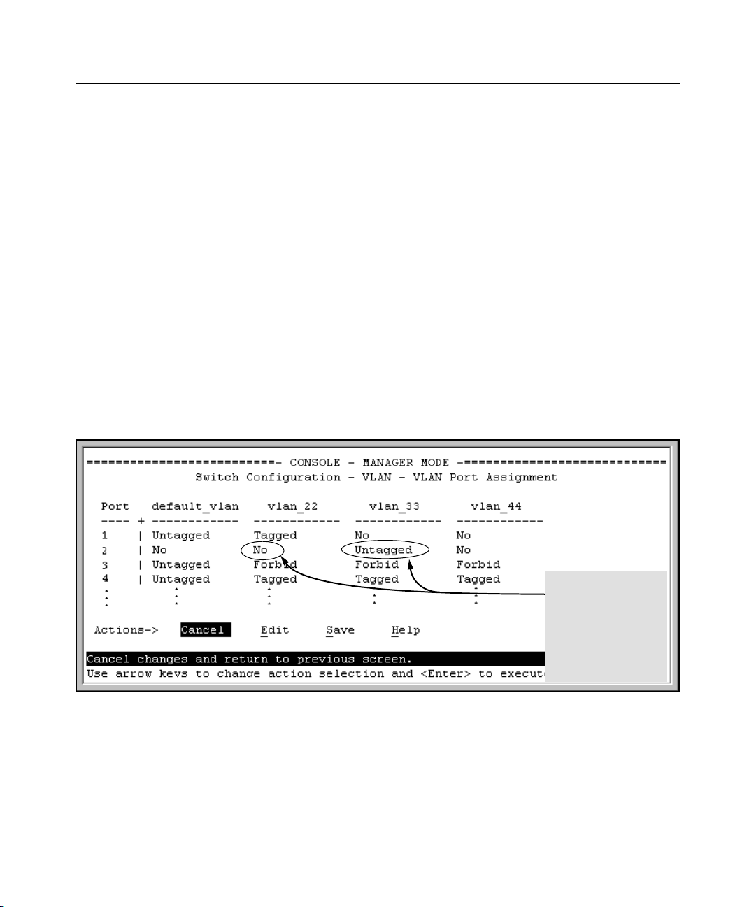
Enhancements in Release F.05.05 through F.05.70
Enhancements in Release F.05.05 through F.05.60
How RADIUS/802.1X Authentication Affects VLAN Operation
Static VLAN Requirement. RADIUS authentication for an 802.1X client on a given port can include
a (static) VLAN requirement. (Refer to the documentation provided with your RADIUS application.)
The static VLAN to which a RADIUS server assigns a client must already exist on the switch. If it
does not exist or is a dynamic VLAN (created by GVRP), authentication fails. Also, for the session to
proceed, the port must be an untagged member of the required VLAN. If it is not, the switch
temporarily reassigns the port as described below.
If the Port Used by the Client Is Not Configured as an Untagged Member of the Required
Static VLAN: When a client is authenticated on port “N”, if port “N” is not already configured as an
untagged member of the static VLAN specified by the RADIUS server, then the switch temporarily
assigns port “N” as an untagged member of the required VLAN (for the duration of the 802.1X session).
At the same time, if port “N” is already configured as an untagged member of another VLAN, port
“N” loses access to that other VLAN for the duration of the session. (This is because a port can be
an untagged member of only one VLAN at a time.)
For example, suppose that a RADIUS-authenticated, 802.1X-aware client on port 2 requires access
to VLAN 22, but VLAN 22 is configured for no access on port 2, and VLAN 33 is configured as untagged
on port 2:
Scenario: An authorized
802.1X client requires
access to VLAN 22 from
port 2. However, access
to VLAN 22 is blocked (not
untagged or tagged) on
port 2 and VLAN 33 is
untagged on port 2.
Figure 16. Example of an Active VLAN Configuration
In figure 16, if RADIUS authorizes an 802.1X client on port 2 with the requirement that the client use
VLAN 22, then:
■ VLAN 22 becomes available as Untagged on port 2 for the duration of the session.
67
Page 79

Enhancements in Release F.05.05 through F.05.70
Enhancements in Release F.05.05 through F.05.60
■ VLAN 33 becomes unavailable to port 2 for the duration of the session (because there can
be only one untagged VLAN on any port).
You can use the show vlan < vlan-id > command to view this temporary change to the active
configuration, as shown below:
■ You can see the temporary VLAN assignment by using the show vlan < vlan-id > command with
the < vlan-id > of the static VLAN that the authenticated client is using.
This entry shows that port 2 is temporarily untagged on
VLAN 22 for an 802.1X session. This is to accommodate an
802.1X client’s access, authenticated by a RADIUS server,
where the server included an instruction to put the client’s
access on VLAN 22.
Note: With the current VLAN configuration (figure 16), the
only time port 2 appears in this show vlan 22 listing is during
an 802.1X session with an attached client. Otherwise, port
2 is not listed.
Figure 17. The Active Configuration for VLAN 22 Temporarily Changes for the 802.1X Session
■ With the preceding in mind, since (static) VLAN 33 is configured as untagged on port 2 (see
figure 16), and since a port can be untagged on only one VLAN, port 2 loses access to VLAN
33 for the duration of the 802.1X session involving VLAN 22. You can verify the temporary
loss of access to VLAN 33 with the show vlan 33 command.
68
Page 80

Enhancements in Release F.05.05 through F.05.70
Enhancements in Release F.05.05 through F.05.60
Even though port 2 is
configured as Untagged on
(static) VLAN 33 (see figure
16), it does not appear in the
VLAN 33 listing while the
802.1X session is using VLAN
22 in the Untagged status.
However, after the 802.1X
session with VLAN 22 ends,
the active configuration
returns port 2 to VLAN 33.
Figure 18. The Active Configuration for VLAN 33 Temporarily Drops Port 22 for the 802.1X Session
When the 802.1X client’s session on port 2 ends, the port discards the temporary untagged VLAN
membership. At this time the static VLAN actually configured as untagged on the port again
becomes available. Thus, when the RADIUS-authenticated 802.1X session on port 2 ends, VLAN
22 access on port 2 also ends, and the untagged VLAN 33 access on port 2 is restored.
After the 802.1X session on
VLAN 22 ends, the active
configuration again
includes VLAN 33 on port 2.
Figure 19. The Active Configuration for VLAN 33 Restores Port 2 After the 802.1X Session Ends
69
Page 81

Enhancements in Release F.05.05 through F.05.70
Enhancements in Release F.05.05 through F.05.60
Notes
Any port VLAN-ID changes you make on 802.1X-aware ports during an 802.1X-authenticated session
do not take effect until the session ends.
With GVRP enabled, a temporary, untagged static VLAN assignment created on a port by 802.1X
authentication is advertised as an existing VLAN. If this temporary VLAN assignment causes the
switch to disable a configured (untagged) static VLAN assignment on the port, then the disabled
VLAN assignment is not advertised. When the 802.1X session ends, the switch:
■ Eliminates and ceases to advertise the temporary VLAN assignment.
■ Re-activates and resumes advertising the temporarily disabled VLAN assignment.
Messages Related to 802.1X Operation
Table 6. 802.1X Operating Messages
Message Meaning
Port < port-list > is not an authenticator.
The ports in the port list have not been enabled as 802.1X
authenticators. Use this command to enable the ports as
authenticators:
HPswitch(config)# aaa port-access
authenticator e 10
Port < port-list > is not a supplicant. Occurs when there is an attempt to change the supplicant
No server(s) responding. This message can appear if you configured the switch for
configuration on a port that is not currently enabled as a
supplicant. Enable the port as a supplicant and then make
the desired supplicant configuration changes. Refer to
“Enabling a Switch Port To Operate as a Supplicant” on
page 58.
EAP-RADIUS or CHAP-RADIUS authentication, but the
switch does not receive a response from a RADIUS server.
Ensure that the switch is configured to access at least one
RADIUS server. (Use show radius.) If you also see the
message Can’t reach RADIUS server <
x.x.x.x >
(page 127).
, try the suggestions listed for that message
70
Page 82

Enhancements in Release F.05.05 through F.05.70
Enhancements in Release F.05.05 through F.05.60
Message Meaning
LACP has been disabled on 802.1X
port(s).
Error configuring port < port-number
>: LACP and 802.1X cannot be run
To maintain security, LACP is not allowed on ports configured for 802.1X authenticator operation. If you configure
port security on a port on which LACP (active or passive) is
configured, the switch removes the LACP configuration,
displays a notice that LACP is disabled on the port(s), and
enables 802.1X on that port.
together.
Also, the switch will not allow you to configure LACP on a
port on which port access (802.1X) is enabled.
IGMP Version 3 Support
When the switch receives an IGMPv3 Join, it accepts the host request and begins forwarding the
IGMP traffic. This means that ports that have not joined the group and are not connected to routers
or the IGMP Querier will not receive the group’s multicast traffic.
The switch does not support the IGMPv3 "Exclude Source" or "Include Source" options in the Join
Reports. Instead, the group is simply joined from all sources.
The switch does not support becoming a version 3 Querier. It will become a version 2 Querier in the
absence of any other Querier on the network.
71
Page 83

Enhancements in Release F.04.08
Enhancements in Release F.04.08
Enhancement Summary Page
Friendly Port Names Enables you to assign optional, meaningful names to physical ports on the
Security Enhancements
SSH Security Provide remote access to management functions on the switches via encrypted
RADIUS Protect access to the switch and monitor use of network resources through a
Port-Based Access
Control (802.1X)
IP Preserve Enable retention of the current IP address and subnet mask (for the switch’s
QoS Priority Enable assignment of non-default priority settings to inbound, untagged packets
Isolated Port Groups Provides an alternative to VLANs in situations where VLANs cannot be used.
switch.
paths between the switch and management station clients capable of SSHv1
operation.
centralized client authentication and accounting service.
Release F.04.08 provides 802.1X port-access control for users requesting
access from multiple points within the network, including application of user
profiles configured on a central RADIUS server. Release F.05.17 updates this
feature to include Open VLAN mode, which changes how the port responds
when it detects a new client. For this reason you will find the documentation for
the Port-Access (802.1X) with Open VLAN mode under "Enhancements in
Release F.05.17" instead of in this section.
default VLAN), and the default gateway address when downloading a configuration file and rebooting the switch. (Operates on switches that use the Manual
IP addressing instead of the default DHCP method.)
received on the switch.
Release F.05.17 updates this feature to include two new groups. For this reason
you will find the documentation for Isolated Port Groups under "Enhancements
in Release F.05.17" instead of in this section.
73
78
102
29
129
132
20
Terminating Remote Sessions Provides a "kill" command to terminate remote Telnet and SSH sessions. 136
Rapid Spanning-Tree (802.1W)
(RSTP)
Provides the functionality for the new Spanning Tree standard, IEEE 802.1w
(RSTP), which is supported by the G.04.04 (or greater) release of your switch
software
137
72
Page 84

Enhancements in Release F.04.08
Using Friendly (Optional) Port Names
Using Friendly (Optional) Port Names
Feature Default Menu CLI Web
Configure Friendly Port Names Standard Port
Numbering
Display Friendly Port Names n/a n/a page 75 n/a
n/a page 74 n/a
This feature enables you to assign alphanumeric port names of your choosing to augment automatically assigned numeric port names. This means you can configure meaningful port names to make
it easier to identify the source of information listed by some Show commands. (Note that this feature
augments port numbering, but does not replace it.)
Configuring and Operating Rules for Friendly Port Names
■ At either the global or context configuration level you can assign a unique name to any port
on the switch. You can also assign the same name to multiple ports.
■ The friendly port names you configure appear in the output of the show name [port-list] , show
config, and show interface <port-number> commands. They do not appear in the output of
other show commands or in Menu interface screens. (See “Displaying Friendly Port Names
with Other Port Data” on page 75.)
■ Friendly port names are not a substitute for port numbers in CLI commands or Menu displays.
■ Trunking ports together does not affect friendly naming for the individual ports. (If you want
the same name for all ports in a trunk, you must individually assign the name to each port.)
■ A friendly port name can have up to 64 contiguous alphanumeric characters.
■ Blank spaces within friendly port names are not allowed, and if used, cause an invalid input
error. (The switch interprets a blank space as a name terminator.)
■ In a port listing, not assigned indicates that the port does not have a name assignment other
than its fixed port number.
■ To retain friendly port names across reboots, you must save the current running-configura-
tion to the startup-config file after entering the friendly port names. (In the CLI, use the write
memory command.)
73
Page 85

Enhancements in Release F.04.08
Using Friendly (Optional) Port Names
Configuring Friendly Port Names
Syntax: interface [e] <port-list> name <port-name-string> Assigns a port name to port-list.
no interface [e] <port-list> name Deletes the port name from port-list.
Configuring a Single Port Name. Suppose that you have connected port 3 on the switch to Bill
Smith’s workstation, and want to assign Bill’s name and workstation IP address (10.25.101.73) as a
port name for port 3:
Figure 20. Example of Configuring a Friendly Port Name
Configuring the Same Name for Multiple Ports. Suppose that you want to use ports 5 through
8 as a trunked link to a server used by a drafting group. In this case you might configure ports 5
through 8 with the name "Draft-Server:Trunk".
Figure 21. Example of Configuring One Friendly Port Name on Multiple Ports
74
Page 86

Enhancements in Release F.04.08
Using Friendly (Optional) Port Names
Displaying Friendly Port Names with Other Port Data
You can display friendly port name data in the following combinations:
■ show name: Displays a listing of port numbers with their corresponding friendly port names
and also quickly shows you which ports do not have friendly name assignments. (show name
data comes from the running-config file.)
■ show interface <port-number>: Displays the friendly port name, if any, along with the traffic
statistics for that port. (The friendly port name data comes from the running-config file.)
■ show config: Includes friendly port names in the per-port data of the resulting configuration
listing. (show config data comes from the startup-config file.)
To List All Ports or Selected Ports with Their Friendly Port Names. This command lists
names assigned to a specific port.
Syntax: show name [ port-list ] Lists the friendly port name with its corresponding
port number and port type. show name alone lists
this data for all ports on the switch.
For example:
Port Without a "Friendly" Name
Friendly port names assigned
in previous examples.
Figure 22. Example of Friendly Port Name Data for All Ports on the Switch
75
Page 87

Enhancements in Release F.04.08
Using Friendly (Optional) Port Names
Port Without a "Friendly" Name
Friendly port names assigned
in previous examples.
Figure 23. Example of Friendly Port Name Data for Specific Ports on the Switch
Including Friendly Port Names in Per-Port Statistics Listings. A friendly port name configured to a port is automatically included when you display the port’s statistics output.
Syntax: show interface <port-number> Includes the friendly port name with the port’s traffic
statistics listing.
For example, if you configure port 1 with the name "O’Connor_10.25.101.43", the show interface
output for this port appears similar to the following:
Friendly Port Name
Figure 24. Example of a Friendly Port Name in a Per-Port Statistics Listing
76
Page 88
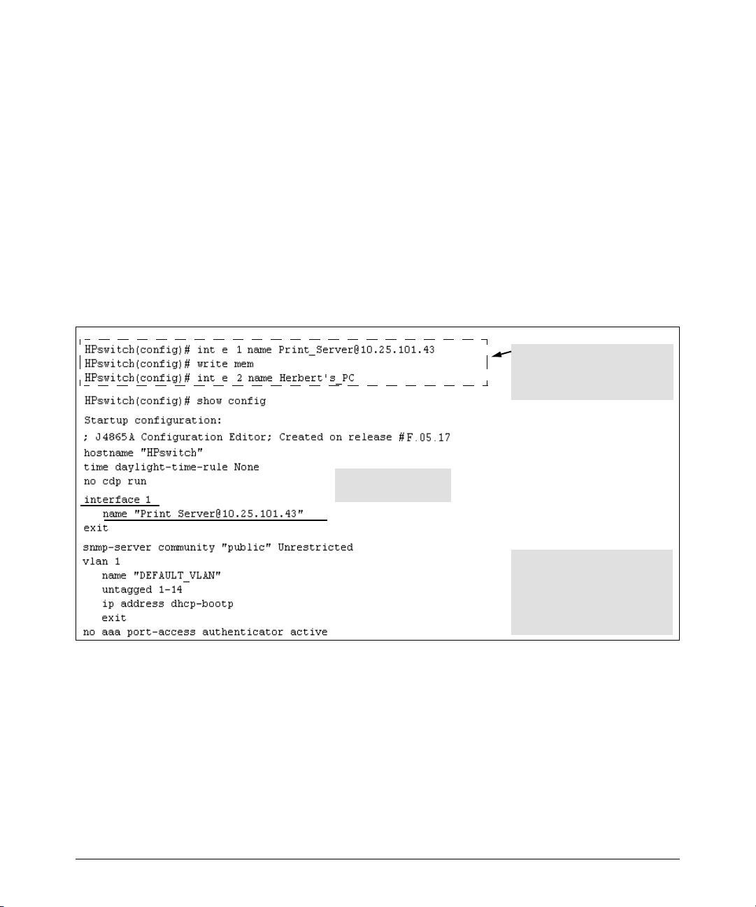
Enhancements in Release F.04.08
Using Friendly (Optional) Port Names
For a given port, if a friendly port name does not exist in the running-config file, the Name line in the
above command output appears as:
Name : not assigned
To Search the Configuration for Ports with Friendly Port Names. This option tells you which
friendly port names have been saved to the startup-config file. (The show config command does not
include ports that have only default settings in the startup-config file.)
Syntax: show config Includes friendly port names in a listing of all interfaces (ports)
configured with non-default settings. Excludes ports that have
neither a friendly port name nor any other non-default
configuration settings.
For example, if you configure port 1 with a friendly port name:
This command sequence saves the
friendly port name for port 1 in the
startup-config file, but does not do
so for the name entered for port 2.
Listing includes friendly
port name for port 1 only.
In this case, show config lists only
port 1. Executing write mem after
entering the name for port 2, and
then executing show config again
would result in a listing that
includes both ports.
Figure 25. Example Listing of the Startup-Config File with a Friendly Port Name Configured (and Saved)
77
Page 89

Enhancements in Release F.04.08
Configuring Secure Shell (SSH)
Configuring Secure Shell (SSH)
Feature Default Menu CLI Web
Generating a public/private key pair on the switch No n/a page 85 n/a
Using the switch’s public key n/a n/a page 87 n/a
Enabling SSH Disabled n/a page 89 n/a
Enabling client public-key authentication Disabled n/a pages 92, 95 n/a
Enabling user authentication Disabled n/a page 92 n/a
The Series 2500 switches use Secure Shell version 1 (SSHv1) to provide remote access to management
functions on the switches via encrypted paths between the switch and management station clients
capable of SSHv1 operation. (The switches can be authenticated by SSHv2 clients that support
SSHv1.) However, to use the reverse option—authenticating an SSHv2 user to the switch—you must
have a method for converting the SSHv2 PEM public-key format to non-encoded ASCII. Refer to "PEM
(Privacy Enhanced Mode)" on page 80.
SSH provides Telnet-like functions but, unlike Telnet, SSH provides encrypted, authenticated transactions. The authentication types include:
■ Client public-key authentication
■ Switch SSH and user password authentication
Client Public Key Authentication (Login/Operator Level) with User Password
Authentication (Enable/Manager Level). This option uses one or more public keys (from
clients) that must be stored on the switch. Only a client with a private key that matches a stored
public key can gain access to the switch. (The same private key can be stored on one or more clients.)
Series 2500
Switch
(SSH
Server)
1.Switch-to-Client SSH authentication
2.Client-to-Switch (login rsa) authentication
3.User-to-Switch (enable password) authentica
tion options:
– Local
– TACACS+
–RADIUS
–None
Figure 26. Client Public Key Authentication Model
SSH
Client
Work-
Station
78
Page 90

Enhancements in Release F.04.08
Configuring Secure Shell (SSH)
Note
SSH in the ProCurve Series 2500 switches is based on the OpenSSH software toolkit. For more information
on OpenSSH, visit
http://www.openssh.com.
Switch SSH and User Password Authentication . This option is a subset of the client public-key
authentication show in figure 26. It occurs if the switch has SSH enabled but does not have login
access (login rsa) configured to authenticate the client’s key. As in figure 26, the switch authenticates
itself to SSH clients. Users on SSH clients then authenticate themselves to the switch (login and/or
enable levels) by providing passwords stored locally on the switch or on a TACACS+ or RADIUS
server. However, the client does not use a key to authenticate itself to the switch.
SSH
Client
Work-
Station
Series 2500
Switch
(SSH
Server)
1. Switch-to-Client SSH authentication.
2. User-to-Switch (login password and
enable password authentication)
options:
– Local
– TACACS+
– RADIUS
Figure 27. Switch/User Authentication
SSH on the Series 2500 switches supports these data encryption methods:
■ 3DES (168-bit)
■ DES (56-bit)
Note
This release supports SSH version 1 only, and all references to SSH in this document are to SSHv1
unless otherwise stated. SSH version 1 uses RSA public key algorithms exclusively, and all references
to either a public or private key mean keys generated using these algorithms unless otherwise noted.
79
Page 91

Enhancements in Release F.04.08
Configuring Secure Shell (SSH)
Terminology
■ SSH Server: An HP Series 2500 switch with SSH enabled.
■ Key Pair: A pair of keys generated by the switch or an SSH client application. Each pair
includes a public key (that can be read by anyone) and a private key that is held internally
in the switch or by a client.
■ PEM (Privacy Enhanced Mode): Refers to an ASCII-formatted client public-key that has
been encoded for greater security. SSHv2 client public-keys are typically stored in the PEM
format. See figures 28 and 29 for examples of PEM-encoded ASCII and non-encoded ASCII
keys.
■ Private Key: An internally generated key used in the authentication process. A private key
generated by the switch is not accessible for viewing or copying. A private key generated by
an SSH client application is typically stored in a file on the client device and, together with
its public key counterpart, can be copied and stored on multiple devices.
■ Public Key: An internally generated counterpart to a private key. Public keys are used for
authenticating a
■ Enable Level: Manager privileges on the switch.
■ Login Level: Operator privileges on the switch.
■ Local password or username: A Manager-level or Operator-level password configured in
the switch.
■ SSH Enabled: (1) A public/private key pair has been generated on the switch (crypto key
generate [rsa]) and (2) SSH is enabled (ip ssh). (You can generate a key pair without enabling
SSH, but you cannot enable SSH without first generating a key pair. See “2. Generating the
Switch’s Public and Private Key Pair” on page 85 and “4. Enabling SSH on the Switch and
Anticipating SSH Client Contact Behavior” on page 89.)
Prerequisite for Using SSH
Before using a Series 2500 switch as an SSH server, you must install a publicly or commercially
available SSH client application on the computer(s) you use for management access to the switch.
If you want client public-key authentication (page 78), then the client program must have the
capability to generate public and private key pairs.
Public Key Format Requirement
Any client application you use for client public-key authentication with the switch must have the
capability to store a public key in non-encoded ASCII format. The switch does not interpret keys
generated using the PEM (Privacy Enhanced Mode) format (also in ASCII characters) that some
SSHv2 client applications use for storing public keys. If your client application stores PEM-encoded
80
Page 92
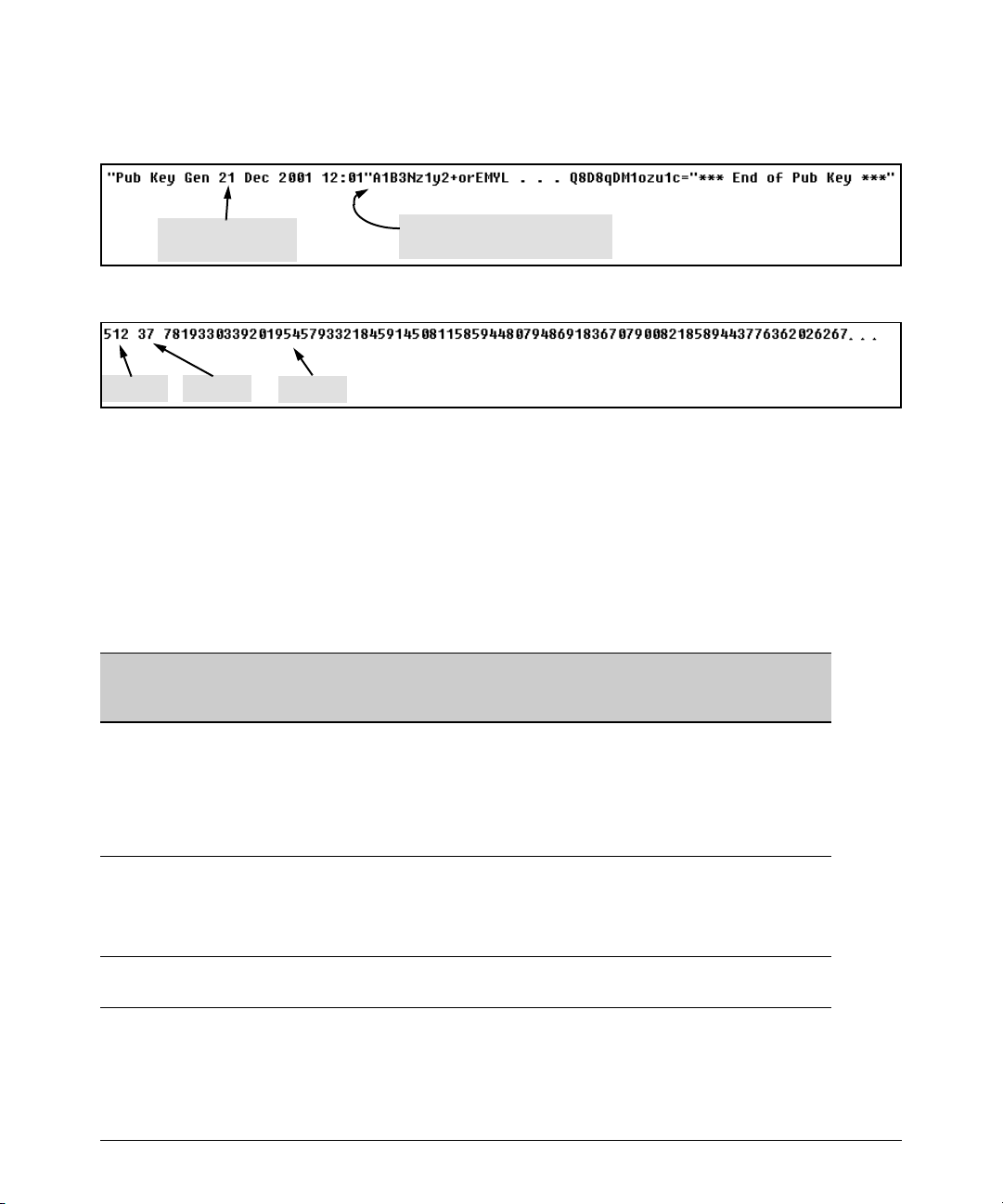
Enhancements in Release F.04.08
Configuring Secure Shell (SSH)
keys by default, check the application software for a key conversion utility or use a third-party key
conversion utility.
Comment describing
public key identity.
Beginning of actual SSHv2 public
key in PEM-Encoded ASCII format.
Figure 28. Example of Public Key in PEM-Encoded ASCII Format Common for SSHv2 Clients
Key Size Key Size
Modulus
Figure 29. Example of Public Key in Non-Encoded ASCII Format (Common for SSHv1 Client Applications)
Steps for Configuring and Using SSH for Switch and Client Authentication
For two-way authentication between the switch and an SSH client, you must use the login (Operator)
level.
Table 7. SSH Options
Switch
Access
Level
Operator
(Login)
Level
Primary SSH
Authentication
ssh login rsa Yes Yes
ssh login Local Yes No Yes local or none
ssh login TACACS Yes No Yes local or none
Authenticate
Switch Public Key
to SSH Clients?
Authenticate
Client Public Key
to the Switch?
1
Primary Switch
Password
Authentication
1
No
Secondary Switch
Password
Authentication
local or none
ssh login RADIUS Yes No Yes local or none
Manager
(Enable)
Level
1
For ssh login rsa, the switch uses client public-key authentication instead of the switch password
options for primary authentication.
ssh enable local Yes No Yes local or none
ssh enable tacacs Yes No Yes local or none
ssh enable radius Yes No Yes local or none
81
Page 93

Enhancements in Release F.04.08
Configuring Secure Shell (SSH)
The general steps for configuring SSH include:
A. Client Preparation
1. Install an SSH client application on a management station you want to use for access to the
switch. (Refer to the documentation provided with your SSH client application.)
2. Optional—If you want the switch to authenticate a client public-key on the client:
a.Either generate a public/private key pair on the client computer or (if your client
application allows) or import a client key pair that you have generated using another
SSH application.
b.Copy the client public key into an ASCII file on a TFTP server accessible to the switch
and download the client public key file to the switch . (The client public key file can hold
up to 10 client keys.) This topic is covered under “To Create a Client-Public-Key Text
File” on page 96.
B. Switch Preparation
1. Assign a login (Operator) and enable (Manager) password on the switch (page 85).
2. Generate a public/private key pair on the switch (page 85).
You need to do this only once. The key remains in the switch even if you reset the switch to
its factory-default configuration. (You can remove or replace this key pair, if necessary.)
3. Copy the switch’s public key to the SSH clients you want to access the switch (page 87).
4. Enable SSH on the switch (page 89).
5. Configure the primary and secondary authentication methods you want the switch to use.
In all cases, the switch will use its host-public-key to authenticate itself when initiating an
SSH session with a client.
•SSH Login (Operator) options:
–Option A:
Primary: Local, TACACS+, or RADIUS password
Secondary: Local password or none
–Option B:
Primary: Client public-key authentication (login rsa — page 95)
Secondary: Local password or none
Note that if you want the switch to perform client public-key authentication, you must
configure the switch with Option B.
•SSH Enable (Manager) options:
Primary: Local, TACACS+, or RADIUS
Secondary: Local password or none
82
Page 94

Enhancements in Release F.04.08
Configuring Secure Shell (SSH)
6. Use your SSH client to access the switch using the switch’s IP address or DNS name (if
allowed by your SSH client application). Refer to the documentation provided with the
client application.
General Operating Rules and Notes
■ Any SSH client application you use must offer backwards-compatibility to SSHv1 keys and
operation.
■ Public keys generated on an SSH client computer must be in ASCII format (used in SSHv1)
if you want to be able to authenticate a client to the switch. The switch does not support
keys generated in the PEM (base-64 Privacy Enhanced Mode) format. See the Note under
“Prerequisite for Using SSH” on page 80.
■ The switch’s own public/private key pair and the (optional) client public key file are stored
in the switch’s flash memory and are not affected by reboots or the erase startup-config
command.
■ Once you generate a key pair on the switch you should avoid re-generating the key pair
without a compelling reason. Otherwise, you will have to re-introduce the switch’s public
key on all management stations (clients) you previously set up for SSH access to the switch.
In some situations this can temporarily allow security breaches.
■ When stacking is enabled, SSH provides security only between an SSH client and the stack
manager. Communications between the stack commander and stack members is not secure.
■ The switch does not support outbound SSH sessions. Thus, if you Telnet from an SSH-secure
switch to another SSH-secure switch, the session is not secure.
83
Page 95

Configuring the Switch for SSH Operation
SSH-Related Commands in This Section
show ip ssh page 91
show ip client-public-key [< babble | fingerprint >] page 98
show ip host-public-key [< babble | fingerprint >] page 88
show authentication page 94
crypto key < generate | zeroize > [rsa] page 86
ip ssh page 90
key-size < 512 | 768 | 1024 > page 90
port < 1 - 65535 > page 90
timeout < 5 .. 120 > page 90
aaa authentication ssh
login < local | tacacs | radius | rsa > page 92, 93
Enhancements in Release F.04.08
Configuring Secure Shell (SSH)
< local | none > page 92
enable < tacacs | radius | local > page 92
< local | none > page 92
copy tftp pub-key-file <tftp server IP> <public key file> page 98
clear public key page 98
84
Page 96

Enhancements in Release F.04.08
Configuring Secure Shell (SSH)
1. Assigning a Local Login (Operator) and Enable (Manager) Password
At a minimum, HP recommends that you always assign at least a Manager password to the switch.
Otherwise, under some circumstances, anyone with Telnet, Web, or serial port access could modify
the switch’s configuration.
To Configure Local Passwords. You can configure both the Operator and Manager password with
one command.
Syntax: password < manager | operator | all >
Figure 30. Example of Configuring Local Passwords
2. Generating the Switch’s Public and Private Key Pair
You must generate a public and private host key pair on the switch. The switch uses this key pair,
along with a dynamically generated session key pair to negotiate an encryption method and session
with an SSH client trying to connect to the switch.
The host key pair is stored in the switch’s flash memory, and only the public key in this pair is readable.
The public key should be added to a "known hosts" file (for example, $HOME/.ssh/known_hosts
on UNIX systems) on the SSH clients who you want to have access to the switch. Some SSH client
applications automatically add the the switch’s public key to a "known hosts" file. Other SSH
applications require you to manually create a known hosts file and place the switch’s public key in
the file. (Refer to the documentation for your SSH client application.)
(The session key pair mentioned above is not visible on the switch. It is a temporary, internally
generated pair used for a particular switch/client session, and then discarded.)
Notes
When you generate a host key pair on the switch, the switch places the key pair in flash memory (and
not in the running-config file). Also, the switch maintains the key pair across reboots, including
power cycles. You should consider this key pair to be "permanent"; that is, avoid re-generating the
key pair without a compelling reason. Otherwise, you will have to re-introduce the switch’s public
key on all management stations you have set up for SSH access to the switch using the earlier pair.
Removing (zeroizing) the switch’s public/private key pair renders the switch unable to engage in SSH
operation and automatically disables IP SSH on the switch. (To verify whether SSH is enabled,
execute show ip ssh.)
85
Page 97

Enhancements in Release F.04.08
Configuring Secure Shell (SSH)
To Generate or Erase the Switch’s Public/Private RSA Host Key Pair. Because the host key
pair is stored in flash instead of the running-config file, it is not necessary to use write memory to save
the key pair. Erasing the key pair automatically disables SSH.
Syntax: crypto key generate [rsa] Generates a public/private key pair for
the switch. If a switch key pair already exists, replaces
it with a new key pair. (See the Note, above.)
crypto key zeroize [rsa] Erases the switch’s public/private key pair
and disables SSH operation.
show ip ssh host-public-key Displays switch’s public key as an ASCII string.
[ babble ] Displays a hash of the switch’s public key in phonetic
format. (See “Displaying the Public Key” on page 88.)
[ fingerprint ] Displays a "fingerprint" of the switch’s public key in
hexadecimal format. (See "Displaying the Public Key"
on page 88.)
For example, to generate and display a new key:
Host Public Key
for the Switch
Figure 31. Example of Generating a Public/Private Host Key Pair for the Switch
Notes
"Zeroizing" the switch’s key automatically disables SSH (sets IP SSH to No). Thus, if you zeroize the
key and then generate a new key, you must also re-enable SSH with the ip ssh command before the
switch can resume SSH operation.
86
Page 98

Enhancements in Release F.04.08
Configuring Secure Shell (SSH)
3. Providing the Switch’s Public Key to Clients
When an SSH client contacts the switch for the first time, the client will challenge the connection
unless you have already copied the key into the client’s "known host" file. Copying the switch’s key
in this way reduces the chance that an unauthorized device can pose as the switch to learn your
access passwords. The most secure way to acquire the switch’s public key for distribution to clients
is to use a direct, serial connection between the switch and a management device (laptop, PC, or
UNIX workstation), as described below.
Note on the Public Key Format
The switch uses SSH version 1, but can be authenticated by SSH version 2 clients that are backwardscompatible to SSHv1. However, if your SSH client supports SSHv2, then it may use the PEM format
for storing the switch’s public key in its "known host" file. In this case, the following procedure will
not work for the client unless you have a method for converting the switch’s ASCII-string public key
into the PEM format. If you do not have a conversion method, then you can still set up authentication
of the switch to the client over the network by simply using your client to contact the switch and
then accepting the resulting challenge that your client should pose to accepting the switch. This
should be acceptable as long as you are confident that there is no "man-in-the-middle" spoofing
attempt during the first contact. Because the client will acquire the switch’s public key after you
accept the challenge, subsequent contacts between the client and the switch should be secure.
The public key generated by the switch consists of three parts, separated by one blank space each:
Key
Size
Encoded
Public Exponent
Encoded
Modulus
896 35 427199470766077426366625060579924214851527933248752021855126493
2934075407047828604329304580321402733049991670046707698543529734853020
0176777055355544556880992231580238056056245444224389955500310200336191
3610469786020092436232649374294060627777506601747146563337525446401
Figure 32. Example of a Public Key Generated by the Switch
(The generated public key on the switch is always 896 bits.)
With a direct serial connection from a management station to the switch:
1. Use a terminal application such as HyperTerminal to display the switch’s public key with the
show ip host-public-key command, as shown in figure 31.
2. Bring up the SSH client’s "known host" file in a text editor such as Notepad as straight ASCII
text, and copy the switch’s public key into the file.
87
Page 99

Enhancements in Release F.04.08
Configuring Secure Shell (SSH)
3. Ensure that there are no line breaks in the text string. (A public key must be an unbroken ASCII
string. Line breaks are not allowed.) For example, if you are using Windows® Notepad, ensure
that W
ord Wrap (in the Edit menu) is disabled, and that the key text appears on a single line.
Figure 33. Example of a Correctly Formatted Public Key (Unbroken ASCII String)
4. Add any data required by your SSH client application. For example Before saving the key to an
SSH client’s "known hosts" file you may have to insert the switch’s IP address:
Inserted IP
Address
Key
Size
Encoded
Public Exponent
Encoded
Modulus
Figure 34. Example of a Switch Public Key Edited To Include the Switch’s IP Address
For more on this topic, refer to the documentation provided with your SSH client application.
Displaying the Public Key. The switch provides three options for displaying its public key. This is
helpful if you need to visually verify that the public key the switch is using for authenticating itself
to a client matches the copy of this key in the client’s "known hosts" file:
■ Non-encoded ASCII numeric string: Requires a client ability to display the keys in the
"known hosts" file in the ASCII format. This method is tedious and error-prone due to the
large ASCII number set. (See figure 33 on page 88.)
■ Phonetic hash: Outputs the key as a relatively short series of alphabetic character groups.
Requires a client ability to convert the key to this format.
■ Hexadecimal hash: Outputs the key as a relatively short series of hexadecimal numbers.
Requires a parallel client ability.
For example, on the switch, you would generate the phonetic and hexadecimal versions of the
switch’s public key in figure 33 as follows:
88
Page 100

Enhancements in Release F.04.08
Configuring Secure Shell (SSH)
Phonetic "Hash" of
Switch’s Public Key
Hexadecimal "Hash"
of the Same Switch
Public Key
Figure 35. Examples of Visual Phonetic and Hexadecimal Conversions of the Switch’s Public Key
Note
The two commands shown in figure 35 convert the displayed format of the switch’s (host) public key
for easier visual comparison of the switch’s public key to a copy of the key in a client’s "known host"
file. The switch always uses an ASCII version (without PEM encoding, or babble or fingerprint
conversion) of its public key for file storage and default display format.
4. Enabling SSH on the Switch and Anticipating SSH Client Contact Behavior
The ip ssh command enables or disables SSH on the switch and modifies parameters the switch uses
for transactions with clients. After you enable SSH, the switch can authenticate itself to SSH clients.
Note
Before enabling SSH on the switch you must generate the switch’s public/private key pair. If you have
not already done so, refer to “2. Generating the Switch’s Public and Private Key Pair” on page 85.
When configured for SSH, the switch uses its host public-key to authenticate itself to SSH clients. If
you also want SSH clients to authenticate themselves to the switch you must do one of the following:
■ Configure SSH on the switch for client public-key authentication at the login (Operator) level,
with (optionally) local, TACACS+, or RADIUS authentication at the enable (Manager) level.
■ Configure SSH on the switch for local, TACACS+, or RADIUS password authentication at
the login and enable levels.
Refer to “5. Configuring the Switch for SSH Authentication” on page 92.
89
 Loading...